Embed Size (px)
Citation preview
EART 118 SeismotectonicsLecture 8
CONCEPTS: Focal Mechanisms Equivalent Body Forces Moment Tensors Complex Sources Supplementary Reading (Optional, for more details/rigor) Lay and Wallace, Modern Global Seismology, Ch. 8 Stein and Wysession, An Introduction to Seismology, Earthquakes and Earth Structure.


Shear dislocation on a planar fault produces a low-degree symmetry pattern of ground motions expanding outward from the source.

The expanding P wave spreads out as an initially spherical 3D wavefront.

P waves and S waves have smoothly varying 4-quadrant patterns of initial particle motion perpendicular to the wavefront (for P) and in the wavefront (for S). These patterns are bisected by nodal lines of no motion between quadrants of opposite sense of motion.

We can project a fault geometry and sense of motion into a 2D display called a focal Mechanism using a stereographic projection. We visualize an imaginary sphere centered on the earthquake hypocenter, called the focal sphere. The projection of the fault plane then bisects the sphere along a line of circumference. In the equatorial plan, this makes a great circle curve. For a given direction of slip on that plane, an orthogonal plane called the auxiliary plane also projects into a great circle curve, which must go through the normal (perpendicular) to the fault plane. The two curves separate quadrants of motion toward the source or away from the source and we call this a source mechanism.

INFER STRESS ORIENTATIONS FROM FOCAL MECHANISMS Simple model predicts faulting on planes 45° from maximum and minimum compressive stresses These stress directions are halfway between nodal planes Most compressive (P) and least compressive stress (T) axes can be found by bisecting the dilatational and compressional quadrants
Stein & Wysession, 2003

Radiation due to motion on the fault plane is what would occur for a pair of force couples, pairs of forces with opposite direction a small distance apart. One couple is oriented in the slip direction with forces on opposite sides of the fault plane, other couple oriented in corresponding direction on opposite sides of the auxiliary plane.
RADIATED SEISMIC WAVES FROM FAULT DESCRIBED BY EQUIVALENT BODY FORCE:
A DOUBLE COUPLE
Pearce, 1977


EQUIVALENT FORCES ARE ONLY SIMPLIFIED MODEL REPRESENTING THE COMPLEX FAULTING PROCESS THAT
ACTUALLY TOOK PLACE
Equivalent body forces are idealizations of the forces associatedwith the deformations that occur during the source deformation. These can put into the equation of motion as point forces actingwith specified magnitude and direction, and that excites accelerations (F = ma) that expand through the medium as P andS waves.
These forces guide us to the actual nonlinear, complex physicalprocess acting at the fault, but don’t give all details.
Often we have other geological and geophysical data, that allow us to favor slip on one of the possible fault planes, and to interpret the faulting in terms of the regional geology and stress field.

4-LOBED P WAVE RADIATION PATTERN
Pearce, 1977

SHEAR WAVE RADIATION PATTERN
Pearce, 1977


Caused some of the highest ground accelerations ever recorded. It illustrates that even a moderate magnitude earthquake can do considerable damage in a populated area. Although the loss of life (58 deaths) was small due to earthquake-resistant construction the $20B damage makes it the most costly earthquake to date in the U.S.
Los Angeles BasinThrust earthquakes indicate shortening
1994 Northridge Ms 6.7
AFTTERSHOCKS
E
N
SSW NNE


CLVD: Compensated Linear Vector Dipole


Composite Source – Shear faulting + explosive expansion + CLVD

Large earthquakes can be represented as a series of smaller planar dislocations with varying seismic moment that collectively describe the overall faulting. It may or may not be on a single planar geometry. We view each discrete part of the rupture as a “subevent”.

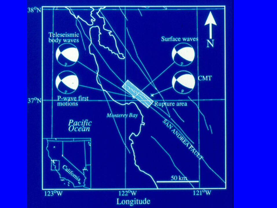
Surface waves: Love and Rayleigh waves have 2D azimuthal radiation patterns as the wave spreads from the source over the surface of the Earth. These are determined by the fault orientation and sense of slip. We can measure the amplitudes (and polarity, or phase) as a function of station azimuth around the source and solve for the gaulting geometry and seismic moment.