Embed Size (px)
Citation preview
E2 Adjustable Speed Driver
Microprocessor Controlled IGBT Drive Inverter Motor Speed Regulator Operating Manual
High Performance Adjustable Speed Micro Drives
E2 Series
110V 0.2~0.75KW ( 0.53~1.6KVA )
220V 0.2~2.2KW ( 0.53~4.0KVA )
440V 0.75~2.2KW ( 1.7~4.0KVA )
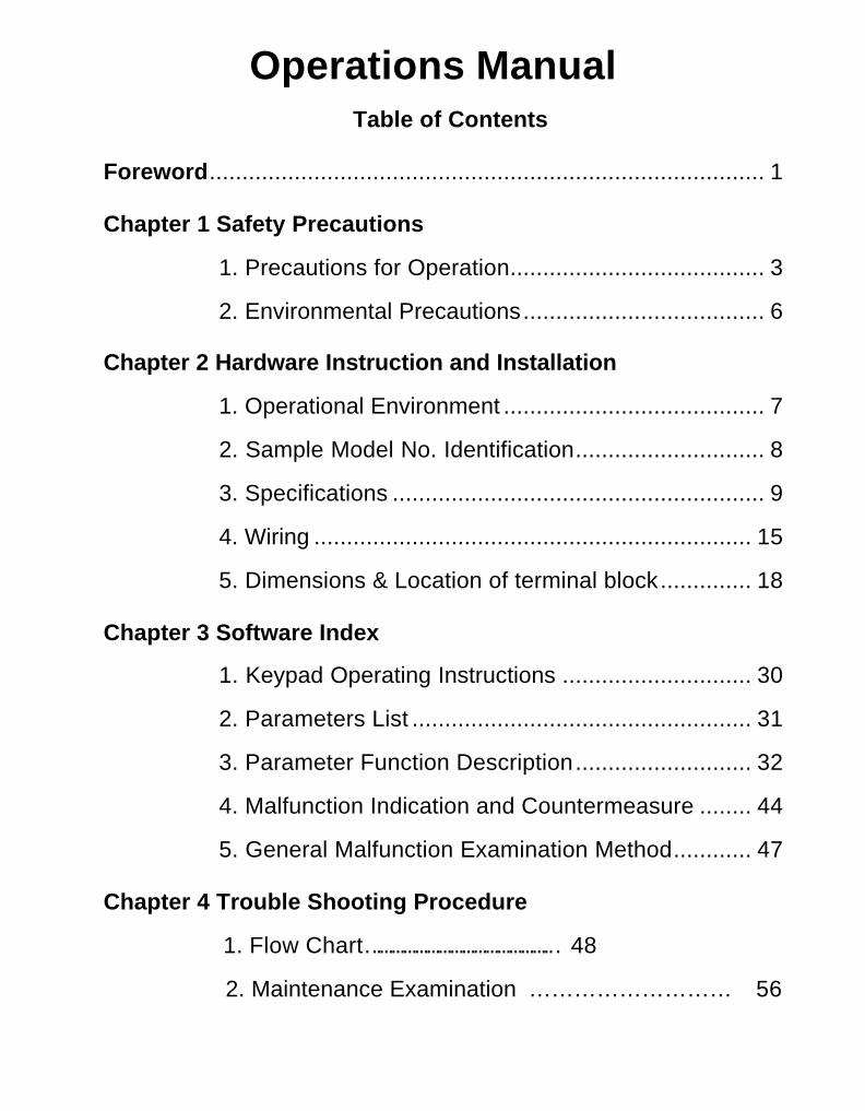
Operations Manual Table of Contents
Foreword..................................................................................... 1
Chapter 1 Safety Precautions
1. Precautions for Operation....................................... 3
2. Environmental Precautions..................................... 6
Chapter 2 Hardware Instruction and Installation
1. Operational Environment ........................................ 7
2. Sample Model No. Identification............................. 8
3. Specifications ......................................................... 9
4. Wiring ................................................................... 15
5. Dimensions & Location of terminal block.............. 18
Chapter 3 Software Index
1. Keypad Operating Instructions ............................. 30
2. Parameters List .................................................... 31
3. Parameter Function Description........................... 32
4. Malfunction Indication and Countermeasure ........ 44
5. General Malfunction Examination Method............ 47
Chapter 4 Trouble Shooting Procedure
1. Flow Chart………………………………………… 48
2. Maintenance Examination … … … … … … … … … 56

This manual may be modified when necessary because of improvement of the product, modification, or changes in specifications, this manual is subject to change without notice.
4KA72X025T01 Ver: 09 2005.08
Distributor
7th., 49, Wu Kong 6Rd. Wu-Ku Industrial Park, Taipei County 248, Taiwan
Tel: 886-2-8990-1111
1
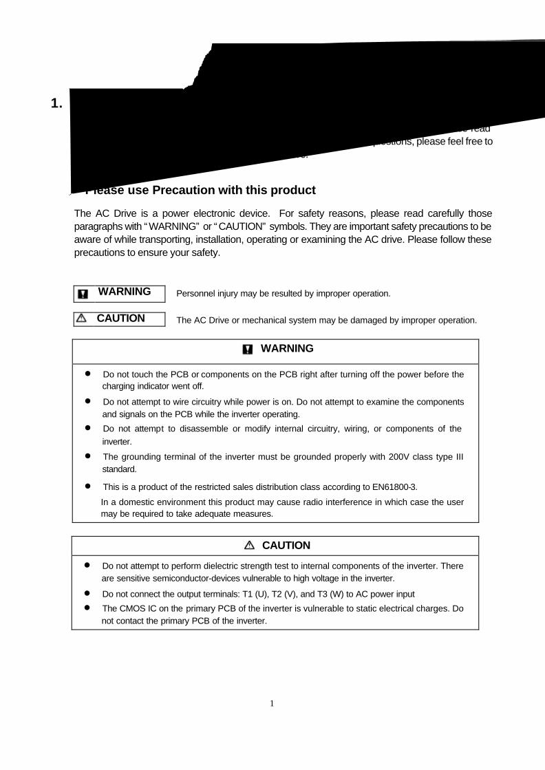
1. Foreword
To fully employ all functions of this AC Drive, and to ensure the safety for its users, please read through this operations manual in detail. Should you have any further questions, please feel free to contact your local distributor or regional representative.
※Please use Precaution with this product
The AC Drive is a power electronic device. For safety reasons, please read carefully those paragraphs with “WARNING” or “CAUTION” symbols. They are important safety precautions to be aware of while transporting, installation, operating or examining the AC drive. Please follow these precautions to ensure your safety.
WARNING Personnel injury may be resulted by improper operation.
CAUTION The AC Drive or mechanical system may be damaged by improper operation.
WARNING
l Do not touch the PCB or components on the PCB right after turning off the power before the charging indicator went off.
l Do not attempt to wire circuitry while power is on. Do not attempt to examine the components and signals on the PCB while the inverter operating.
l Do not attempt to disassemble or modify internal circuitry, wiring, or components of the inverter.
l The grounding terminal of the inverter must be grounded properly with 200V class type III standard.
l This is a product of the restricted sales distribution class according to EN61800-3.
In a domestic environment this product may cause radio interference in which case the user may be required to take adequate measures.
CAUTION l Do not attempt to perform dielectric strength test to internal components of the inverter. There
are sensitive semiconductor-devices vulnerable to high voltage in the inverter.
l Do not connect the output terminals: T1 (U), T2 (V), and T3 (W) to AC power input l The CMOS IC on the primary PCB of the inverter is vulnerable to static electrical charges. Do
not contact the primary PCB of the inverter.
2
2. Examination before installation
Every inverter has been fully tested and examined before shipment. Please carry out the following examination procedures after unpacking your AC inverter. l Check to see if the model number of the AC inverter matches the model number of the AC
inverter that you ordered. l Check to see whether any damage occurred to the AC inverter during shipment. Do not
connect the AC inverter to the power supply if there is any sign of damage.
Report this to a regional sale representative if you find any abnormal condition as mentioned above.
3
Chapter 1: Safety Precaution
1. Precautions for operation
Before turning ON power
CAUTION Choose the appropriate power source with correct voltage settings for the input voltage specification of the AC inverter.
WARNING
Special care must be taken while wiring the primary circuitry panel. The L1 and L2 terminal must be connected to the input power source and must not be mistakenly connected to T1, T2 or T3 out put terminals. This may damage the inverter when the power is turned on.
CAUTION l Do not attempt to transport the inverter by the front of the cover. Securely hold the
inverter by the heat-sink mounting chassis to prevent the inverter from falling, this may cause personnel injury or damage to the inverter itself.
l Install the inverter onto a firm metal base plate or another non-flammable type material. Do not install the inverter onto or nearby any flammable material.
l An additional cooling fan may need to be installed if several inverters are installed into one control panel. The inside temperature inside an enclosed panel should be below 40 degrees to avoid overheating.
l Turn off the power supply before proceeding to remove or perform any work on any panel. Carry out installation procedures according to instructions given in order to avoid a situation resulting in an operational malfunction.
l Suitable for use on a circuit capable of delivering not more than 5000 RMS symmetrical amperes. 240 Volts maximum.
l This product is not provided with over speed protection.
l Only intended for use in a pollution degree 2 macro environment or equivalent
4
When power is applied
WARNING
l Do not attempt to install or remove input or output connectors of inverter when the power supply is turned on. Otherwise, the inverter may be damaged due to the surge peak caused by the insertion or removal of power.
l When momentary power loss is longer than 2 seconds (the large of horse power, the longer of time), the inverter does not have enough storage power to control the circuit; Therefore, when power is regenerated, the operation of the inverter is based on the setup of F_10 and the condition of external switch, this is considered to be「restart」in the following paragraphs.
l When the momentary power loss is short, the inverter still has enough storage power to control the circuit; therefore, when power is regenerated, the inverter will automatically start operation again depends on the setup of F_23.
When restart the inverter, the operation of the inverter is based on the setup of F_10 and the condition of external switch (FWD/REV button). Attention: the restart operation is irrelevant with F_23/F_24.
(1) When F_10=0, the inverter will not start after restart. (2) When F_10=1 and the external switch (FWD/REV button) is OFF, the inverter
will not start after restart. (3) When F_10=1 and the external switch (FWD/REV button) is ON, the inverter
will start automatically after restart. Attention: Base on safety reason, please turn off the external switch (FWD/REV button) after power loss to avoid possible damage to the machine and the human body after sudden regeneration of power.
5
Under Operation
WARNING
Do not use a separate device to switch ON or OFF motor during operation. Otherwise, the inverter may experience an over-current breakdown.
WARNING
l Do not remove the front cover of the inverter when the power is ON to avoid personnel injury caused by electrical shock.
l When the automatic restart function is enabled, the motor and machinery will be restarted automatically.
CAUTION l Do not touch the heat-sink base during operation. l The inverter can be easily operated from a low-speed to high-speed range. Please
reconfirm the operating range of motor and the machinery you are controlling. l Do not examining the signals on the PCB of the inverter when it is under operation. l All inverters are properly adjusted and set before delivery.
CAUTION Do not proceed with disassemble or examination procedure before ensuring that the power is off and the Power LED extinguished.
When performing an examination or maintenance
CAUTION Inverter environment should be within temp: –10 OC ~ +40 OC, humidity under 95% RH without condensing.
CAUTION After the removal of shield sticker, the environment temperature should be within –10OC ~ +50OC and humidity under 95% RH without condensing. Besides, the inverter should be free from water dripping or metal dust.
6
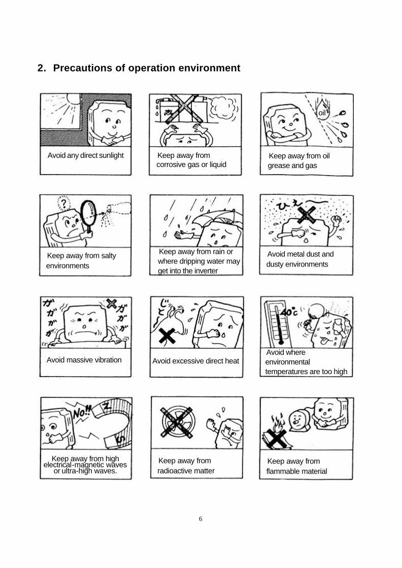
2. Precautions of operation environment
Avoid any direct sunlight Keep away from corrosive gas or liquid
Keep away from oil grease and gas
Keep away from salty environments
Keep away from rain or where dripping water may get into the inverter
Avoid metal dust and dusty environments
Avoid massive vibration
Avoid excessive direct heat
Avoid where environmental temperatures are too high
Keep away from high electrical-magnetic waves
or ultra-high waves. Keep away from radioactive matter
Keep away from flammable material
oil
7
Chapter 2: Hardware Instructions and Installation
1. Operational Environment
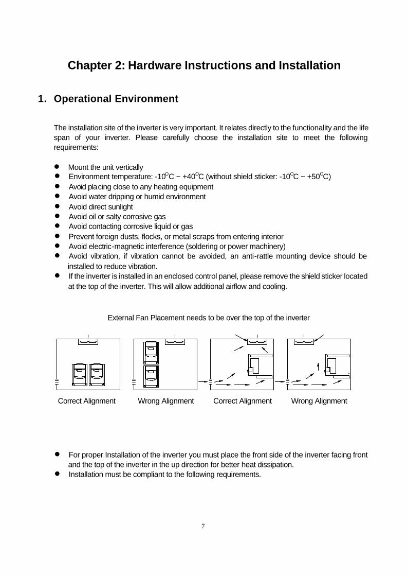
The installation site of the inverter is very important. It relates directly to the functionality and the life span of your inverter. Please carefully choose the installation site to meet the following requirements: l Mount the unit vertically l Environment temperature: -10OC ~ +40OC (without shield sticker: -10OC ~ +50OC) l Avoid placing close to any heating equipment l Avoid water dripping or humid environment l Avoid direct sunlight l Avoid oil or salty corrosive gas l Avoid contacting corrosive liquid or gas l Prevent foreign dusts, flocks, or metal scraps from entering interior l Avoid electric-magnetic interference (soldering or power machinery) l Avoid vibration, if vibration cannot be avoided, an anti-rattle mounting device should be
installed to reduce vibration. l If the inverter is installed in an enclosed control panel, please remove the shield sticker located
at the top of the inverter. This will allow additional airflow and cooling.
l For proper Installation of the inverter you must place the front side of the inverter facing front and the top of the inverter in the up direction for better heat dissipation.
l Installation must be compliant to the following requirements.
External Fan Placement needs to be over the top of the inverter
Correct Alignment Wrong Alignment Correct Alignment Wrong Alignment
8
5cm 5cm5cm
T-VERTER
Installationdirection
12cm
12cm
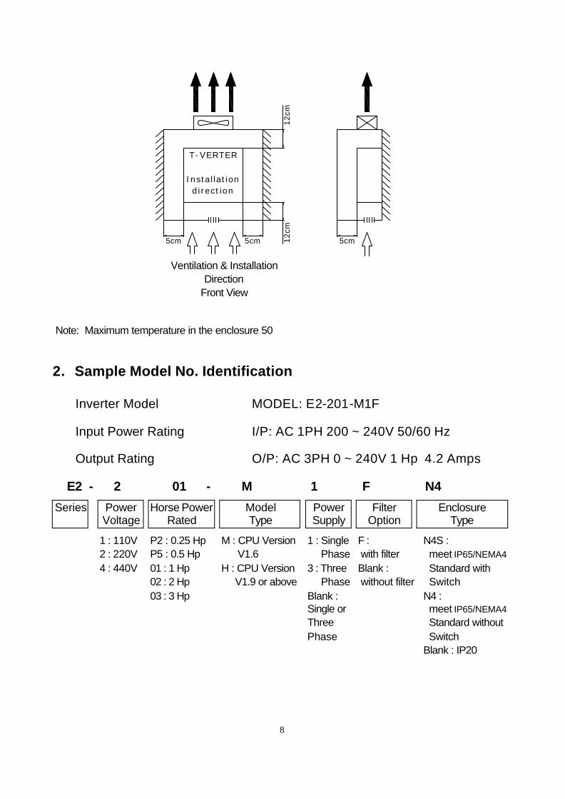
Note: Maximum temperature in the enclosure 50
2. Sample Model No. Identification
Inverter Model ⇓ MODEL: E2-201-M1F
Input Power Rating ⇓ I/P: AC 1PH 200 ~ 240V 50/60 Hz
Output Rating ⇓ O/P: AC 3PH 0 ~ 240V 1 Hp 4.2 Amps
E2 - 2 01 - M 1 F N4
Series Power Voltage
Horse Power Rated
Model Type
Power Supply
Filter Option
Enclosure Type
Ventilation & Installation Direction
Front View
1 : 110V 2 : 220V 4 : 440V
P2 : 0.25 Hp P5 : 0.5 Hp 01 : 1 Hp 02 : 2 Hp 03 : 3 Hp
M : CPU Version V1.6 H : CPU Version V1.9 or above
1 : Single Phase 3 : Three Phase Blank : Single or Three Phase
F : with filter Blank : without filter
N4S : meet IP65/NEMA4 Standard with Switch N4 : meet IP65/NEMA4 Standard without Switch Blank : IP20
9
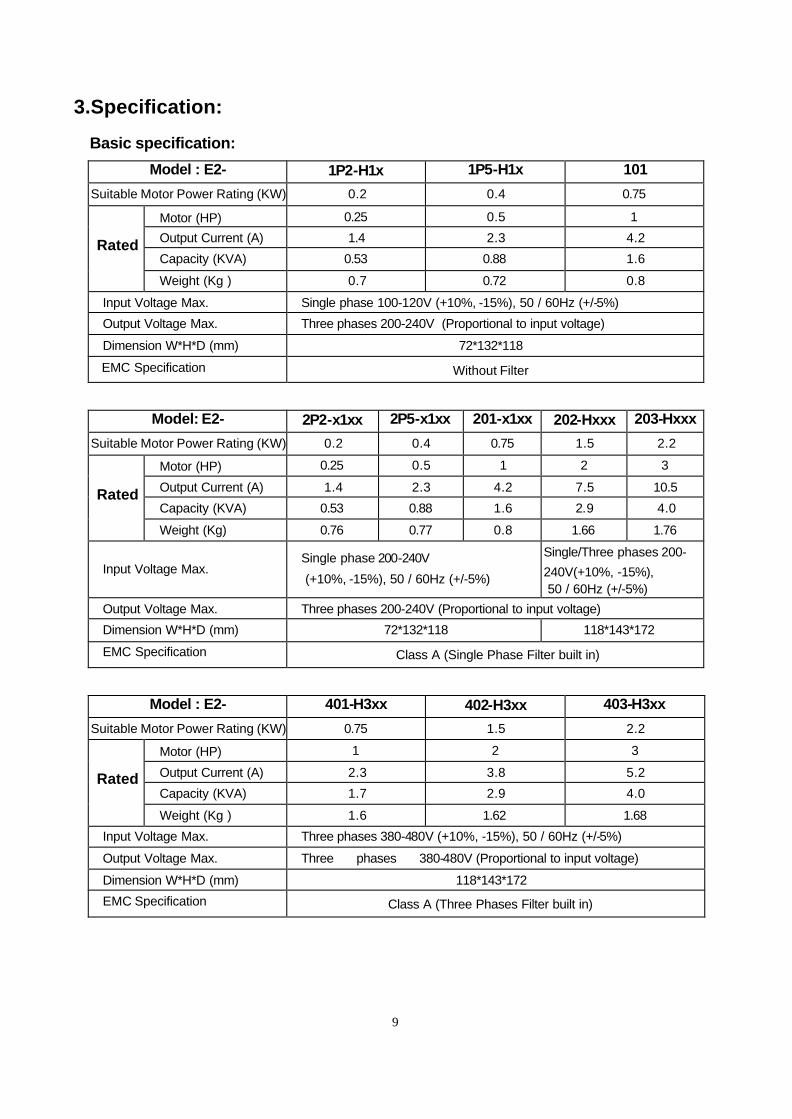
3.Specification:
Basic specification:
Model : E2- 1P2-H1x 1P5-H1x 101
Suitable Motor Power Rating (KW) 0.2 0.4 0.75
Motor (HP) 0.25 0.5 1
Output Current (A) 1.4 2.3 4.2
Capacity (KVA) 0.53 0.88 1.6
Rated
Weight (Kg ) 0.7 0.72 0.8
Input Voltage Max. Single phase 100-120V (+10%, -15%), 50 / 60Hz (+/-5%)
Output Voltage Max. Three phases 200-240V (Proportional to input voltage)
Dimension W*H*D (mm) 72*132*118
EMC Specification Without Filter
Model: E2- 2P2-x1xx 2P5-x1xx 201-x1xx 202-Hxxx 203-Hxxx
Suitable Motor Power Rating (KW) 0.2 0.4 0.75 1.5 2.2
Motor (HP) 0.25 0.5 1 2 3
Output Current (A) 1.4 2.3 4.2 7.5 10.5
Capacity (KVA) 0.53 0.88 1.6 2.9 4.0
Rated
Weight (Kg) 0.76 0.77 0.8 1.66 1.76
Input Voltage Max. Single phase 200-240V
(+10%, -15%), 50 / 60Hz (+/-5%)
Single/Three phases 200- 240V(+10%, -15%), 50 / 60Hz (+/-5%)
Output Voltage Max. Three phases 200-240V (Proportional to input voltage)
Dimension W*H*D (mm) 72*132*118 118*143*172
EMC Specification Class A (Single Phase Filter built in)
Model : E2- 401-H3xx 402-H3xx 403-H3xx
Suitable Motor Power Rating (KW) 0.75 1.5 2.2
Motor (HP) 1 2 3
Output Current (A) 2.3 3.8 5.2
Capacity (KVA) 1.7 2.9 4.0
Rated
Weight (Kg ) 1.6 1.62 1.68
Input Voltage Max. Three phases 380-480V (+10%, -15%), 50 / 60Hz (+/-5%)
Output Voltage Max. Three phases 380-480V (Proportional to input voltage)
Dimension W*H*D (mm) 118*143*172
EMC Specification Class A (Three Phases Filter built in)
10
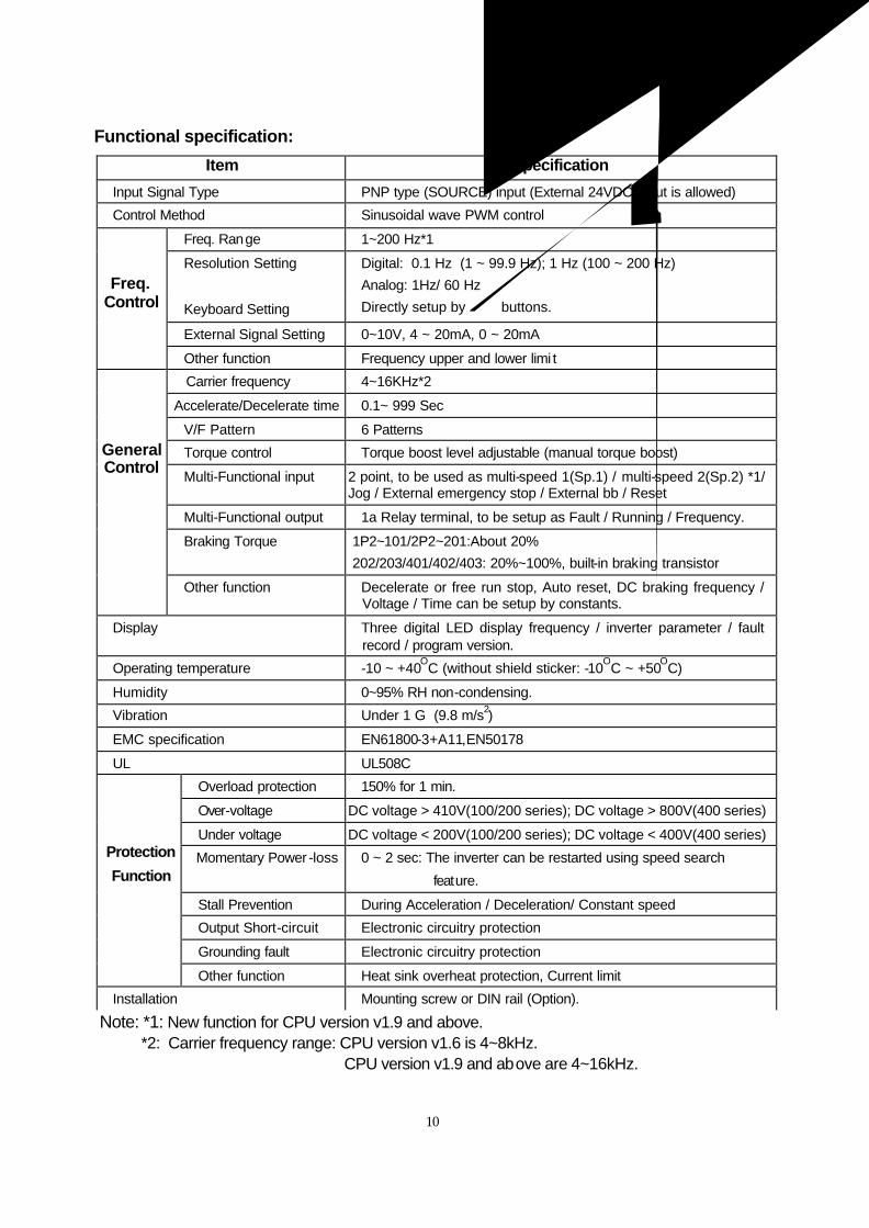
Functional specification:
Item Specification
Input Signal Type PNP type (SOURCE) input (External 24VDC Input is allowed)
Control Method Sinusoidal wave PWM control
Freq. Range 1~200 Hz*1
Resolution Setting Digital: 0.1 Hz (1 ~ 99.9 Hz); 1 Hz (100 ~ 200 Hz) Analog: 1Hz/ 60 Hz
Keyboard Setting Directly setup by buttons.
External Signal Setting 0~10V, 4 ~ 20mA, 0 ~ 20mA
Freq. Control
Other function Frequency upper and lower limi t
Carrier frequency 4~16KHz*2
Accelerate/Decelerate time 0.1~ 999 Sec
V/F Pattern 6 Patterns
Torque control Torque boost level adjustable (manual torque boost)
Multi-Functional input 2 point, to be used as multi-speed 1(Sp.1) / multi-speed 2(Sp.2) *1/ Jog / External emergency stop / External bb / Reset
Multi-Functional output 1a Relay terminal, to be setup as Fault / Running / Frequency.
Braking Torque 1P2~101/2P2~201:About 20% 202/203/401/402/403: 20%~100%, built-in braking transistor
General Control
Other function Decelerate or free run stop, Auto reset, DC braking frequency / Voltage / Time can be setup by constants.
Display Three digital LED display frequency / inverter parameter / fault record / program version.
Operating temperature -10 ~ +40OC (without shield sticker: -10OC ~ +50OC)
Humidity 0~95% RH non-condensing.
Vibration Under 1 G (9.8 m/s2)
EMC specification EN61800-3+A11,EN50178
UL UL508C
Overload protection 150% for 1 min.
Over-voltage DC voltage > 410V(100/200 series); DC voltage > 800V(400 series)
Under voltage DC voltage < 200V(100/200 series); DC voltage < 400V(400 series)
Momentary Power -loss 0 ~ 2 sec: The inverter can be restarted using speed search
feature.
Stall Prevention During Acceleration / Deceleration/ Constant speed
Output Short-circuit Electronic circuitry protection
Grounding fault Electronic circuitry protection
Protection
Function
Other function Heat sink overheat protection, Current limit
Installation Mounting screw or DIN rail (Option).
Note: *1: New function for CPU version v1.9 and above. *2: Carrier frequency range: CPU version v1.6 is 4~8kHz. CPU version v1.9 and above are 4~16kHz.
11
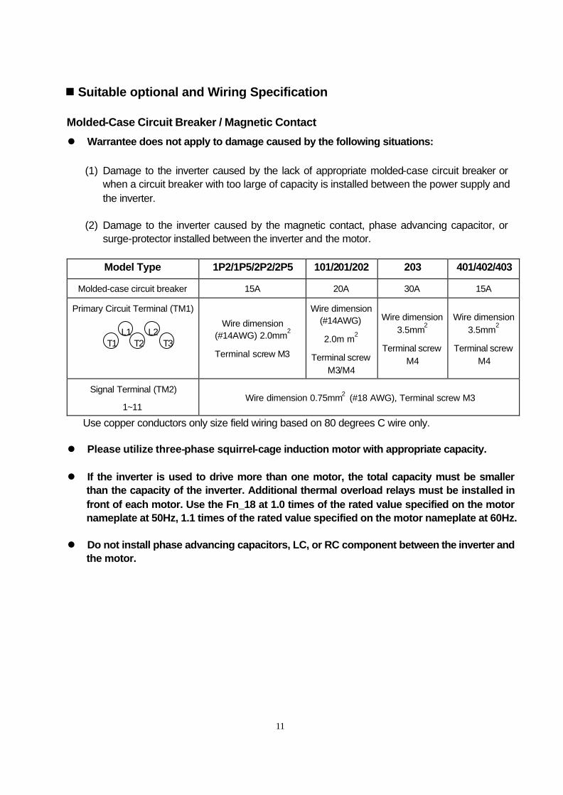
n Suitable optional and Wiring Specification
Molded-Case Circuit Breaker / Magnetic Contact
l Warrantee does not apply to damage caused by the following situations:
(1) Damage to the inverter caused by the lack of appropriate molded-case circuit breaker or when a circuit breaker with too large of capacity is installed between the power supply and the inverter.
(2) Damage to the inverter caused by the magnetic contact, phase advancing capacitor, or
surge-protector installed between the inverter and the motor.
Model Type 1P2/1P5/2P2/2P5 101/201/202 203 401/402/403
Molded-case circuit breaker 15A 20A 30A 15A
Primary Circuit Terminal (TM1)
Wire dimension (#14AWG) 2.0mm2
Terminal screw M3
Wire dimension (#14AWG)
2.0m m2
Terminal screw M3/M4
Wire dimension 3.5mm2
Terminal screw M4
Wire dimension 3.5mm2
Terminal screw M4
Signal Terminal (TM2)
1~11 Wire dimension 0.75mm2 (#18 AWG), Terminal screw M3
Use copper conductors only size field wiring based on 80 degrees C wire only. l Please utilize three-phase squirrel-cage induction motor with appropriate capacity. l If the inverter is used to drive more than one motor, the total capacity must be smaller
than the capacity of the inverter. Additional thermal overload relays must be installed in front of each motor. Use the Fn_18 at 1.0 times of the rated value specified on the motor nameplate at 50Hz, 1.1 times of the rated value specified on the motor nameplate at 60Hz.
l Do not install phase advancing capacitors, LC, or RC component between the inverter and
the motor.
T3 T1 T2 L1 L2
12
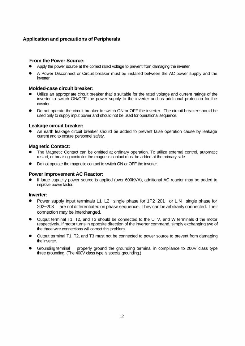
Application and precautions of Peripherals
From the Power Source: l Apply the power source at the correct rated voltage to prevent from damaging the inverter.
l A Power Disconnect or Circuit breaker must be installed between the AC power supply and the inverter.
Molded-case circuit breaker: l Utilize an appropriate circuit breaker that’s suitable for the rated voltage and current ratings of the
inverter to switch ON/OFF the power supply to the inverter and as additional protection for the inverter.
l Do not operate the circuit breaker to switch ON or OFF the inverter. The circuit breaker should be used only to supply input power and should not be used for operational sequence.
Leakage circuit breaker: l An earth leakage circuit breaker should be added to prevent false operation cause by leakage
current and to ensure personnel safety. Magnetic Contact: l The Magnetic Contact can be omitted at ordinary operation. To utilize external control, automatic
restart, or breaking controller the magnetic contact must be added at the primary side.
l Do not operate the magnetic contact to switch ON or OFF the inverter. Power improvement AC Reactor: l If large capacity power source is applied (over 600KVA), additional AC reactor may be added to
improve power factor. Inverter: l Power supply input terminals L1, L2(single phase for 1P2~201)or L,N(single phase for
202~203) are not differentiated on phase sequence. They can be arbitrarily connected. Their connection may be interchanged.
l Output terminal T1, T2, and T3 should be connected to the U, V, and W terminals of the motor respectively. If motor turns in opposite direction of the inverter command, simply exchanging two of the three wire connections will correct this problem.
l Output terminal T1, T2, and T3 must not be connected to power source to prevent from damaging the inverter.
l Grounding terminal properly ground the grounding terminal in compliance to 200V class type three grounding. (The 400V class type is special grounding.)
13
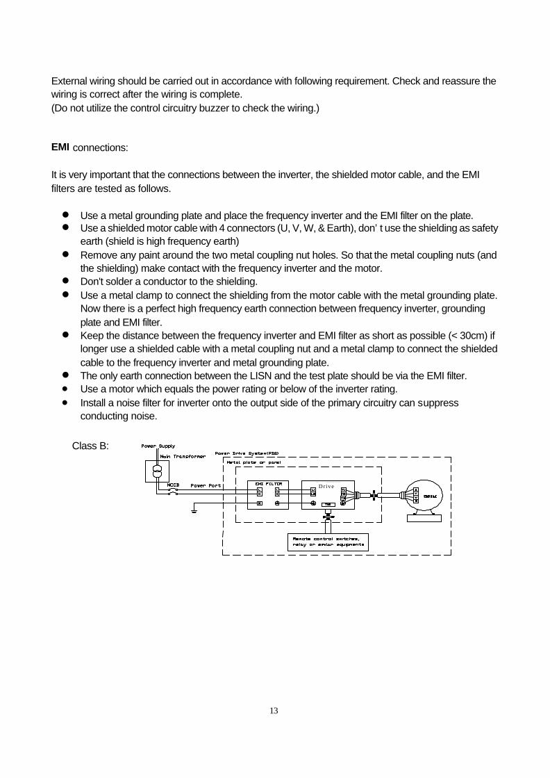
External wiring should be carried out in accordance with following requirement. Check and reassure the wiring is correct after the wiring is complete. (Do not utilize the control circuitry buzzer to check the wiring.) EMI connections: It is very important that the connections between the inverter, the shielded motor cable, and the EMI filters are tested as follows. l Use a metal grounding plate and place the frequency inverter and the EMI filter on the plate. l Use a shielded motor cable with 4 connectors (U, V, W, & Earth), don’t use the shielding as safety
earth (shield is high frequency earth) l Remove any paint around the two metal coupling nut holes. So that the metal coupling nuts (and
the shielding) make contact with the frequency inverter and the motor. l Don't solder a conductor to the shielding. l Use a metal clamp to connect the shielding from the motor cable with the metal grounding plate.
Now there is a perfect high frequency earth connection between frequency inverter, grounding plate and EMI filter.
l Keep the distance between the frequency inverter and EMI filter as short as possible (< 30cm) if longer use a shielded cable with a metal coupling nut and a metal clamp to connect the shielded cable to the frequency inverter and metal grounding plate.
l The only earth connection between the LISN and the test plate should be via the EMI filter. l Use a motor which equals the power rating or below of the inverter rating. l Install a noise filter for inverter onto the output side of the primary circuitry can suppress
conducting noise.
Drive
Class B:
14
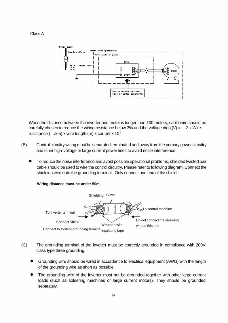
Class A:
When the distance between the inverter and motor is longer than 100 meters, cable wire should be carefully chosen to reduce the wiring resistance below 3% and the voltage drop (V) = √3 x Wire resistance (Ω/km) x wire length (m) x current x 10-3
(B) Control circuitry wiring must be separated terminated and away from the primary power circuitry
and other high-voltage or large-current power lines to avoid noise interference. l To reduce the noise interference and avoid possible operational problems, shielded twisted pair
cable should be used to wire the control circuitry. Please refer to following diagram. Connect the shielding wire onto the grounding terminal. Only connect one end of the shield.
Wiring distance must be under 50m.
(C) The grounding terminal of the inverter must be correctly grounded in compliance with 200V class type three grounding.
l Grounding wire should be wired in accordance to electrical equipment (AWG) with the length
of the grounding wire as short as possible.
l The grounding wire of the inverter must not be grounded together with other large current loads (such as soldering machines or large current motors). They should be grounded separately.
Shielding Glove
To Inverter terminal
Connect to system grounding terminal Wrapped with
insulating tape
To control machine
Do not connect the shielding
wire at this end
Drive
Connect Shield
15
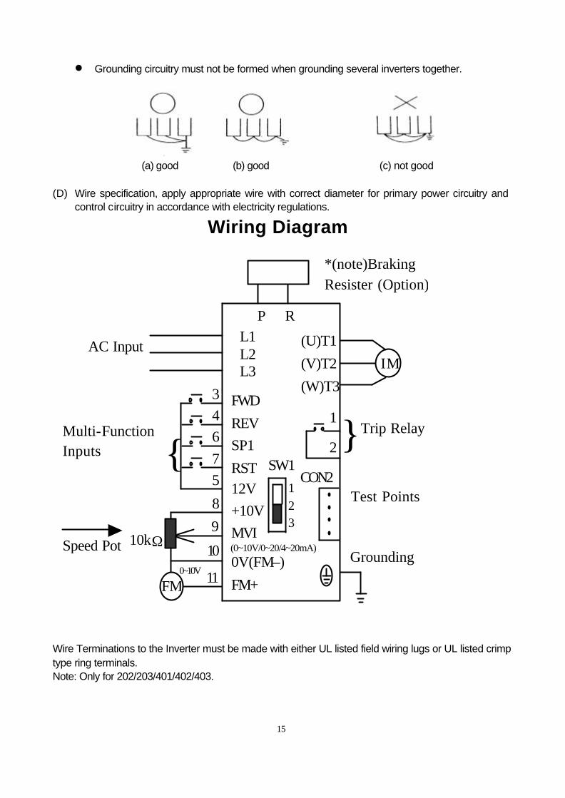
l Grounding circuitry must not be formed when grounding several inverters together.
(a) good (b) good (c) not good (D) Wire specification, apply appropriate wire with correct diameter for primary power circuitry and
control circuitry in accordance with electricity regulations.
Wiring Diagram
Wire Terminations to the Inverter must be made with either UL listed field wiring lugs or UL listed crimp type ring terminals. Note: Only for 202/203/401/402/403.
P R
L1 (L) L2 L3 (N) FWD
REV
SP1
RST 12V
+10V
MVI (0~10V/0~20/4~20mA)
0V(FM–)
FM+
*(note)Braking Resister (Option)
SW1
1 2 3
(U)T1
(V)T2
(W)T3 1 2 CON2
AC Input IM
Trip Relay
Test Points
Grounding
3 4 6
7 5
Multi-Function Inputs
8
9
10 11 FM
Speed Pot 10kΩ
0~10V
16
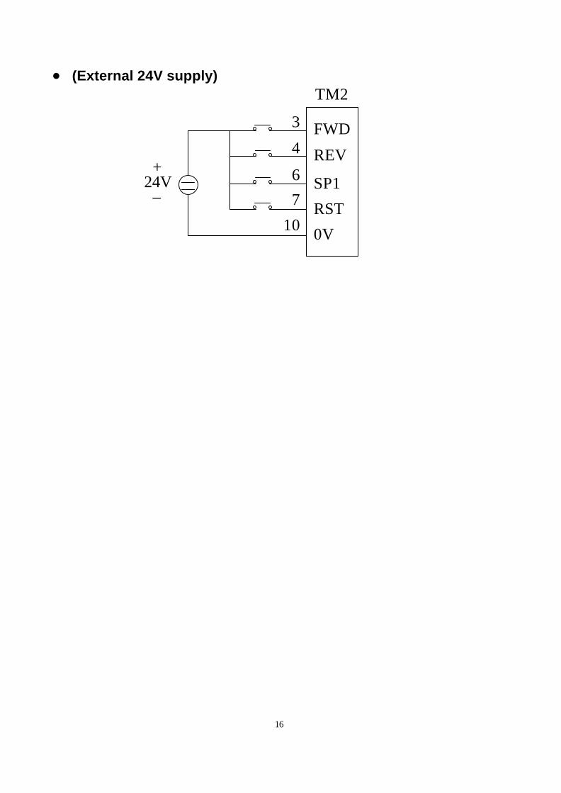
l (External 24V supply)
TM2
FWD
REV
SP1
RST
0V
3
4
6
7
10
+24V –
17
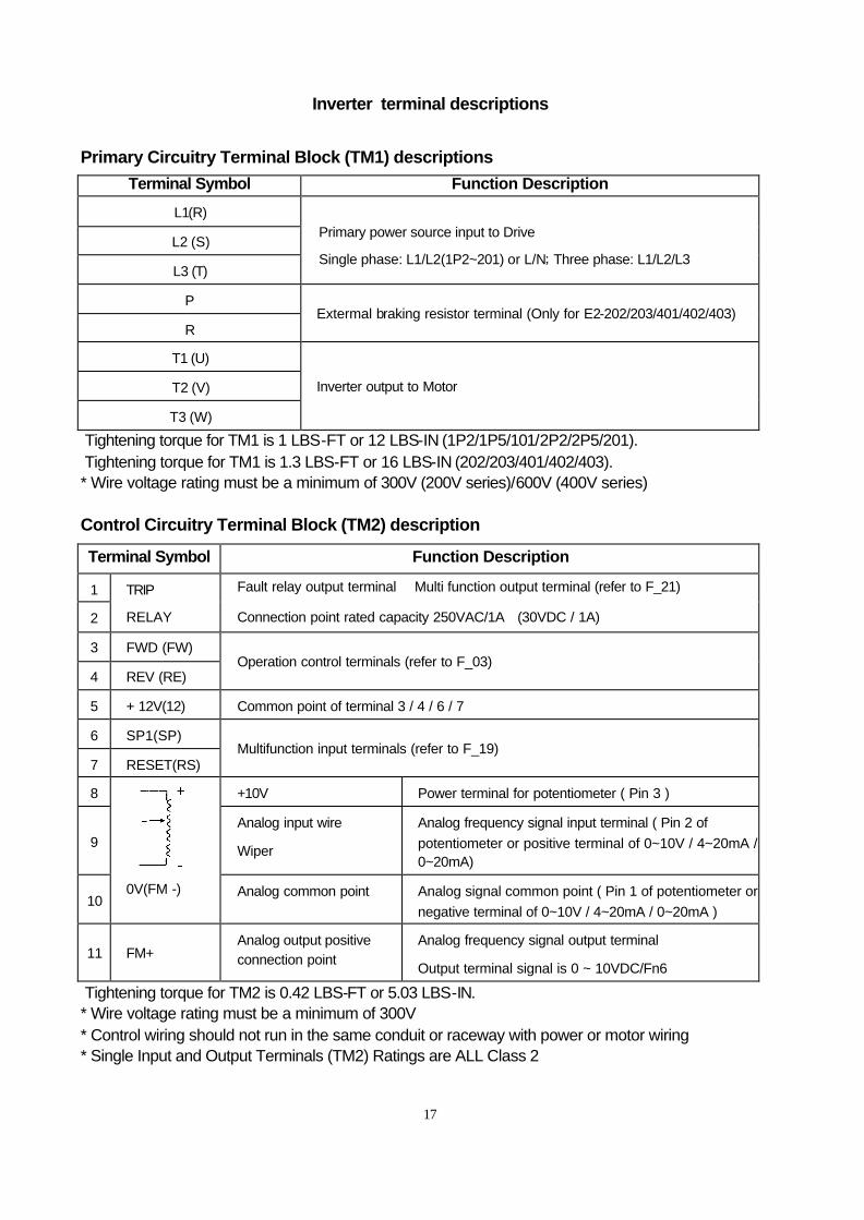
Inverter terminal descriptions
Primary Circuitry Terminal Block (TM1) descriptions
Terminal Symbol Function Description
L1(R)
L2 (S)
L3 (T)
Primary power source input to Drive
Single phase: L1/L2(1P2~201) or L/N; Three phase: L1/L2/L3
P
R Extermal braking resistor terminal (Only for E2-202/203/401/402/403)
T1 (U)
T2 (V)
T3 (W)
Inverter output to Motor
Tightening torque for TM1 is 1 LBS-FT or 12 LBS-IN (1P2/1P5/101/2P2/2P5/201). Tightening torque for TM1 is 1.3 LBS-FT or 16 LBS-IN (202/203/401/402/403). * Wire voltage rating must be a minimum of 300V (200V series)/600V (400V series) Control Circuitry Terminal Block (TM2) description
Terminal Symbol Function Description
1
2
TRIP
RELAY
Fault relay output terminal ﹠Multi function output terminal (refer to F_21)
Connection point rated capacity 250VAC/1A (30VDC / 1A)
3 FWD (FW)
4 REV (RE) Operation control terminals (refer to F_03)
5 + 12V(12) Common point of terminal 3 / 4 / 6 / 7
6 SP1(SP)
7 RESET(RS) Multifunction input terminals (refer to F_19)
8 +10V Power terminal for potentiometer ( Pin 3 )
9 Analog input wire
Wiper
Analog frequency signal input terminal ( Pin 2 of potentiometer or positive terminal of 0~10V / 4~20mA / 0~20mA)
10
0V(FM -) Analog common point Analog signal common point ( Pin 1 of potentiometer or
negative terminal of 0~10V / 4~20mA / 0~20mA )
11 FM+ Analog output positive connection point
Analog frequency signal output terminal
Output terminal signal is 0 ~ 10VDC/Fn6
Tightening torque for TM2 is 0.42 LBS-FT or 5.03 LBS-IN. * Wire voltage rating must be a minimum of 300V * Control wiring should not run in the same conduit or raceway with power or motor wiring * Single Input and Output Terminals (TM2) Ratings are ALL Class 2
18
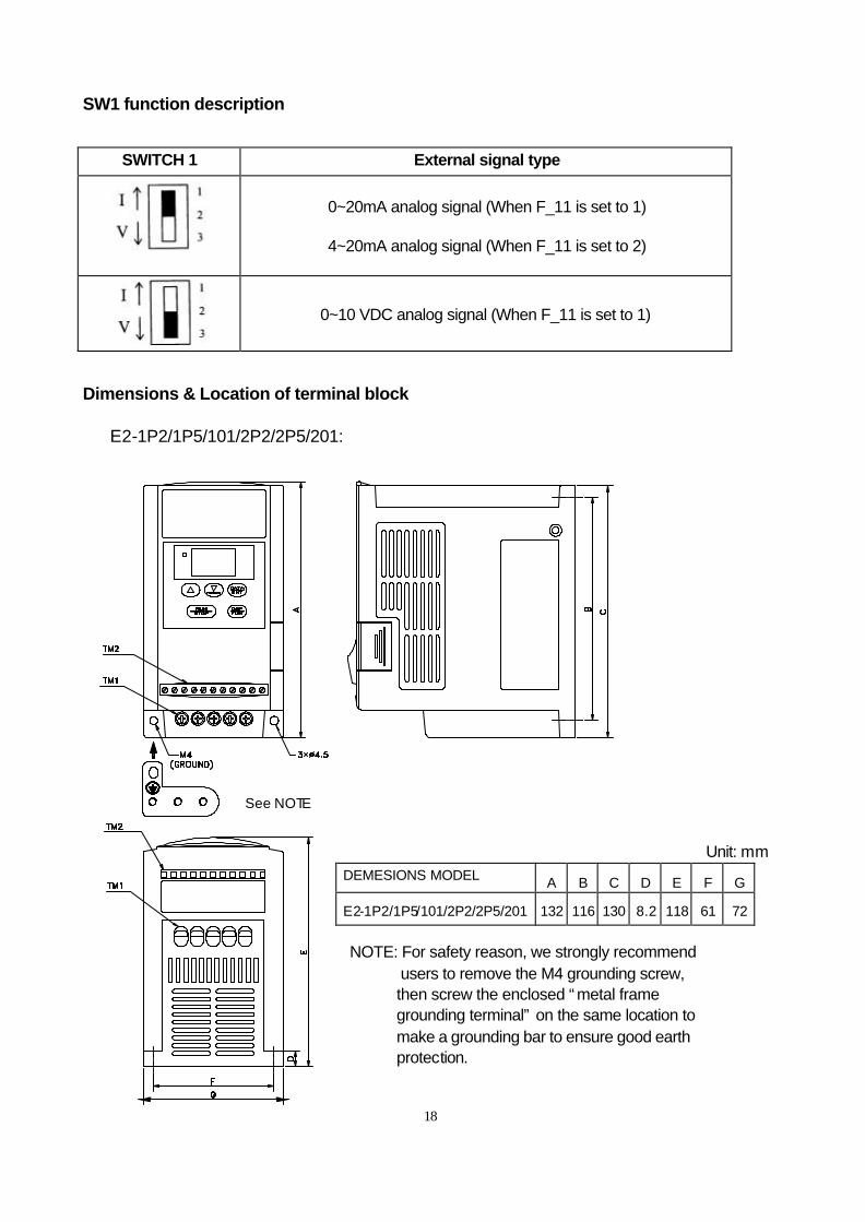
SW1 function description
SWITCH 1 External signal type
0~20mA analog signal (When F_11 is set to 1)
4~20mA analog signal (When F_11 is set to 2)
0~10 VDC analog signal (When F_11 is set to 1)
Dimensions & Location of terminal block E2-1P2/1P5/101/2P2/2P5/201:
Unit: mm DEMESIONS MODEL A B C D E F G
E2-1P2/1P5/101/2P2/2P5/201 132 116 130 8.2 118 61 72
NOTE: For safety reason, we strongly recommend users to remove the M4 grounding screw,
then screw the enclosed “metal frame grounding terminal” on the same location to make a grounding bar to ensure good earth protection.
See NOTE
19
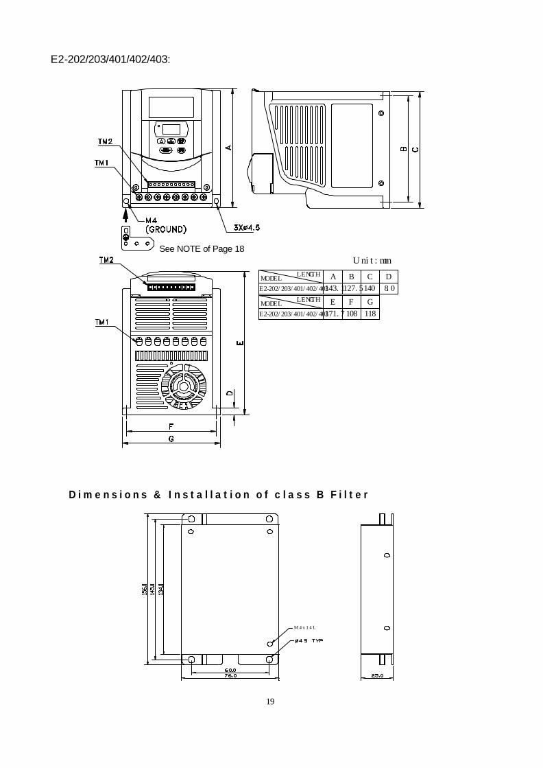
E2-202/203/401/402/403:
D i m e n s i o n s & I n s t a l l a t i o n o f c l a s s B F i l t e r
M 4 x 1 4 L
MODELLENGTHA
143.1127.5
B
140
C D
8.0
LENGTH
E2-202/203/401/402/403
MODEL
171.7
E
108
F
118
G
Unit:mm
E2-202/203/401/402/403
See NOTE of Page 18
20
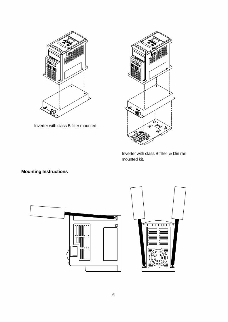
Mounting Instructions
Inverter with class B filter mounted.
Inverter with class B filter & Din rail mounted kit.
21
Mounting plate Pull mounting plate
1
2
Screwdriver
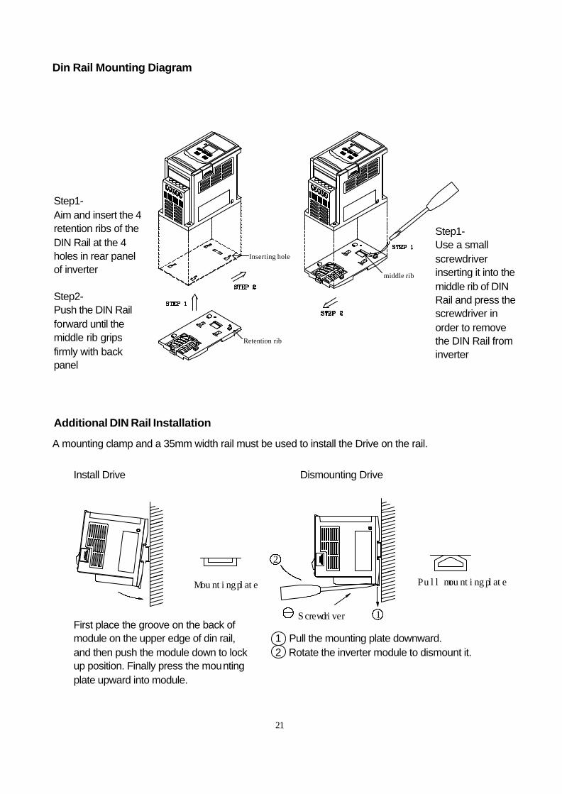
Din Rail Mounting Diagram
Additional DIN Rail Installation
A mounting clamp and a 35mm width rail must be used to install the Drive on the rail.
middle rib
Retention rib
Inserting hole
Step1- Aim and insert the 4 retention ribs of the DIN Rail at the 4 holes in rear panel of inverter Step2- Push the DIN Rail forward until the middle rib grips firmly with back panel
Step1- Use a small screwdriver inserting it into the middle rib of DIN Rail and press the screwdriver in order to remove the DIN Rail from inverter
Install Drive Dismounting Drive
1 Pull the mounting plate downward. 2 Rotate the inverter module to dismount it.
First place the groove on the back of module on the upper edge of din rail, and then push the module down to lock up position. Finally press the mounting plate upward into module.
22
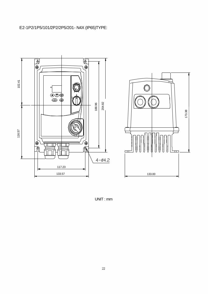
E2-1P2/1P5/101/2P2/2P5/201- N4X (IP65)TYPE:
UNIT : mm
STOP
0 1
R
RUN
ENTDATA
FUNDSP
RESETF
0
116.
57
102.
41
117.23
133.57
188.
96
204.
82
133.00
173.
38
23
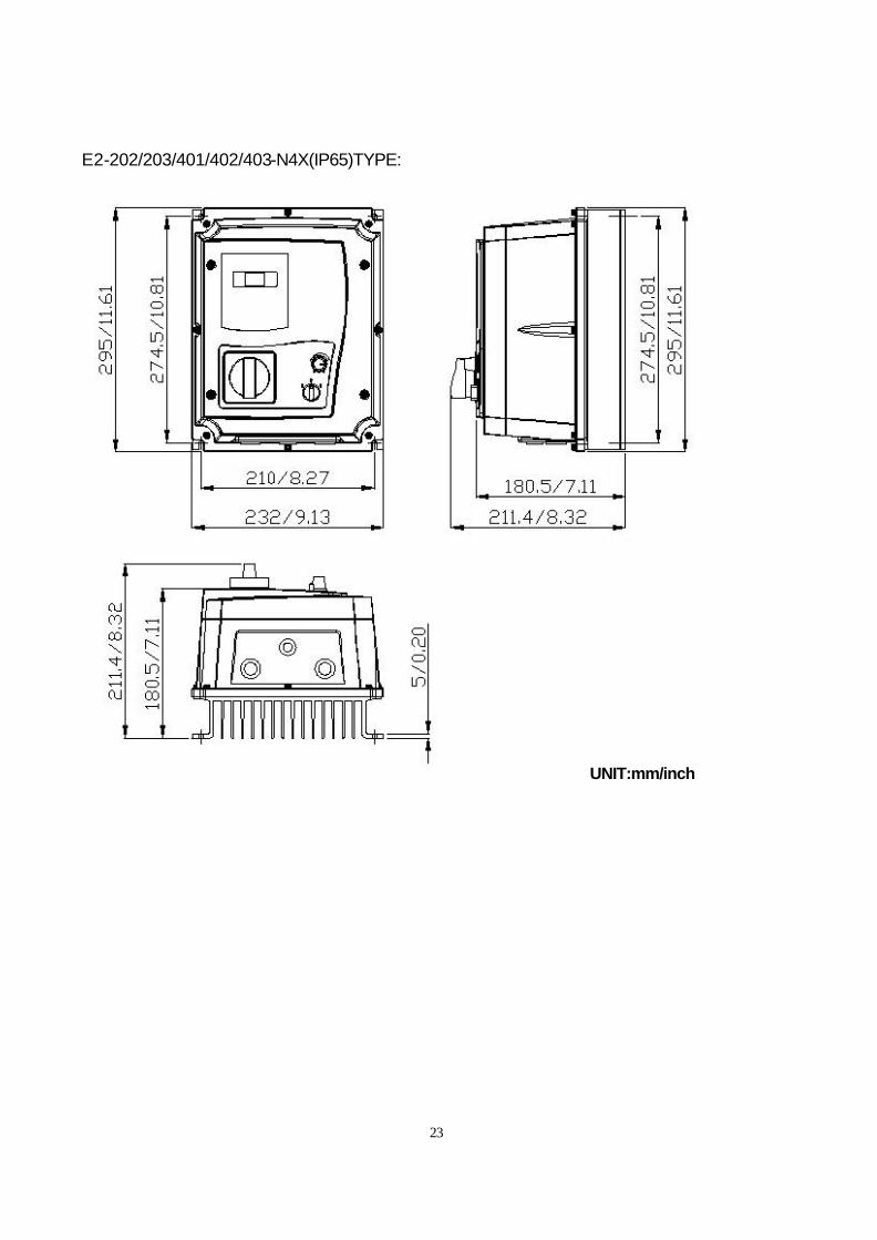
E2-202/203/401/402/403-N4X(IP65)TYPE:
UNIT:mm/inch
24
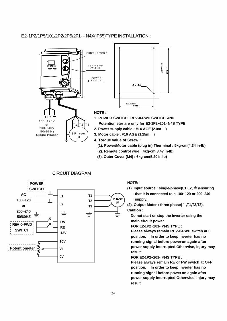
E2-1P2/1P5/101/2P2/2P5/201- - N4X(IP65)TYPE INSTALLATION :
CIRCUIT DIAGRAM
NOTE:
(1). Input source : single-phase(L1,L2, )ensuring
that it is connected to a 100~120 or 200~240
supply.
(2). Output Moter : three-phase( ,T1,T2,T3).
Caution : ‧Do not start or stop the inverter using the
main circuit power. ‧FOR E2-1P2~201- -N4S TYPE :
Please always remain REV-0-FWD switch at 0
position. In order to keep inverter has no running signal before power-on again after power supply interrupted.Otherwise, injury may result. ‧FOR E2-1P2~201- -N4S TYPE :
Please always remain RE or FW switch at OFF position. In order to keep inverter has no
running signal before power-on again after power supply interrupted.Otherwise, injury may
result.
3 PHASE
IM
10V
VI
0V
FW
RE
12V
L1 L2
T1
T2
T3
POWER
SWITCH
REV-0-FWD
SWITCH
Potentiometer
AC
100~120
or
200~240
50/60HZ
S W I T C HPOWER
Potentiometer
R E V - 0 - F W DS W I T C H
L 1 L 2
R U NS T O P
3 Phases IM
T 1 T 2 T 3
E N T
D S PF U N
DATARESET
(2) .Remote control wire : 4 kg-cmThermina l : 5 kg-cm
2. Moto r cab le : #16 AWG
(1).Power/Motor cable (plug-in) 3 . Torque value of Screw :
1 . Power supp ly cab le : #14 AWG
m m
Note :
mm
100~120Vor
200-240V 50 /60 Hz S ing le Phases
NOTE :
1. POWER SWITCH , REV-0-FWD SWITCH AND
Potentiometer are only for E2-1P2~201- N4S TYPE
2. Power supply cable : #14 AGE (2.0m )
3. Motor cable : #16 AGE (1.25m )
4. Torque value of Screw :
(1). Power/Motor cable (plug in) Therminal : 5kg-cm(4.34 in-lb)
(2). Remote control wire : 4kg-cm(3.47 in-lb)
(3). Outer Cover (M4) : 6kg-cm(5.20 in-lb)
123.40 mm
198.
90 m
m
25
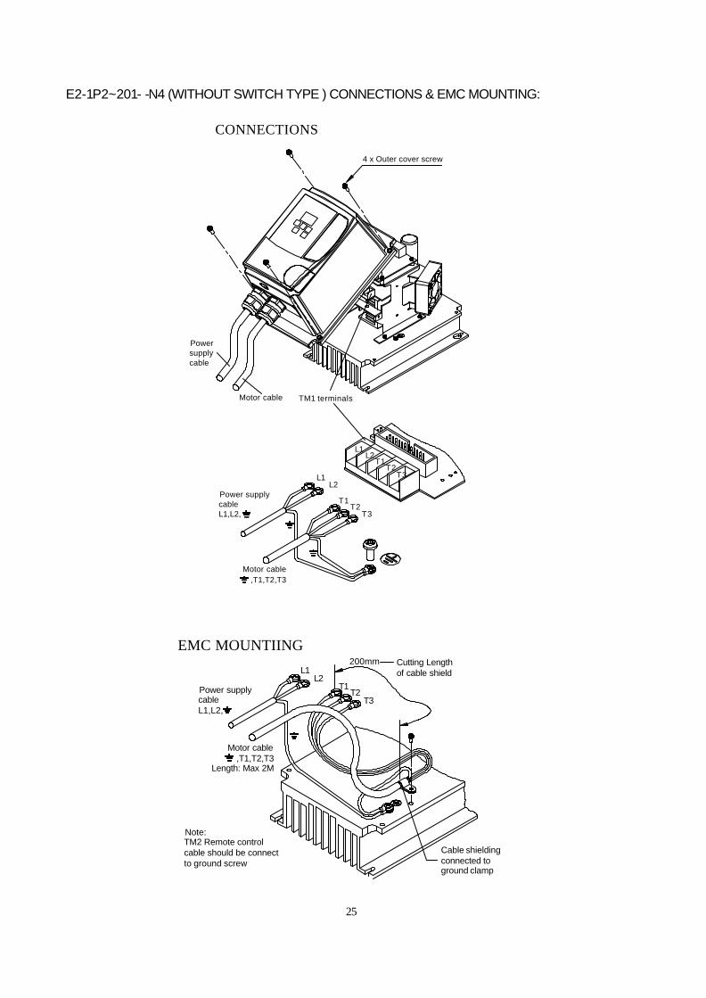
E2-1P2~201- -N4 (WITHOUT SWITCH TYPE ) CONNECTIONS & EMC MOUNTING:
T1L2
L1
T2T3
Motor cable,T1,T2,T3
L1,L2,
Power supply cable
200mm Cutting Lengthof cable shield
Cable shielding connected to ground clamp
EMC MOUNTIING
Length: Max 2M
Note:TM2 Remote control cable should be connect to ground screw
T3
L1L2
T2T1
L1L2
T1T2
T3
4 x Outer cover screw
CONNECTIONS
,T1,T2,T3Motor cable
TM1 terminals
Power supply cableL1,L2,
Motor cable
Powersupplycable
T1L2
L1
T2T3
Motor cable,T1,T2,T3
L1,L2,
Power supply cable
200mm Cutting Lengthof cable shield
Cable shielding connected to ground clamp
EMC MOUNTIING
Length: Max 2M
Note:TM2 Remote control cable should be connect to ground screw
26
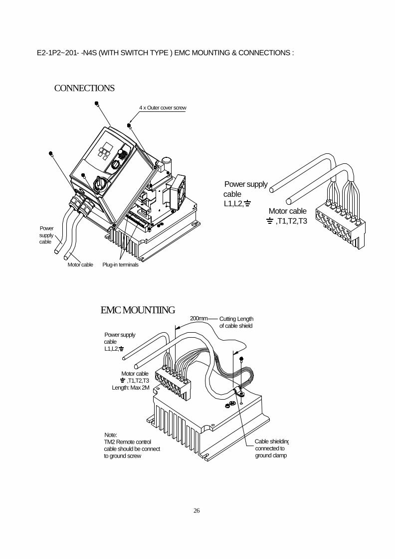
E2-1P2~201- -N4S (WITH SWITCH TYPE ) EMC MOUNTING & CONNECTIONS :
4 x Outer cover screw
CONNECTIONS
Plug-in terminals
Powersupplycable
Motor cable
EMC MOUNTIING
Power supply cableL1,L2,
Cutting Lengthof cable shield
200mm
Cable shielding connected to ground clamp
Note:TM2 Remote control cable should be connect to ground screw
Length: Max 2M,T1,T2,T3
Motor cable
,T1,T2,T3Motor cable
Power supply cableL1,L2,
27
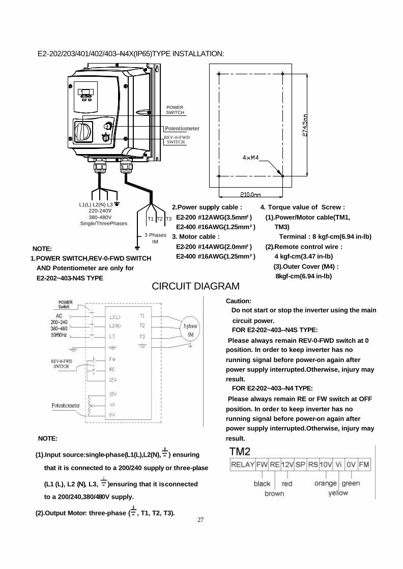
E2-202/203/401/402/403—N4X(IP65)TYPE INSTALLATION:
T1 T2 T3
3 Phases IM
220-240V 380-480V Single/ThreePhases
DATA
FUNDSP
ENT
RUN
RESET
STOP
REV-0-FWDSWITCH
Potentiometer
POWERSWITCH
L1(L) L2(N) L3
2.Power supply cable : 4. Torque value of Screw :
E2-200 #12AWG(3.5mm²) (1).Power/Motor cable(TM1,
E2-400 #16AWG(1.25mm²) TM3)
3. Motor cable : Terminal : 8 kgf-cm(6.94 in-lb)
E2-200 #14AWG(2.0mm²) (2).Remote control wire :
E2-400 #16AWG(1.25mm²) 4 kgf-cm(3.47 in-lb)
(3).Outer Cover (M4) :
8kgf-cm(6.94 in-lb)
NOTE:
1.POWER SWITCH,REV-0-FWD SWITCH
AND Potentiometer are only for
E2-202~403-N4S TYPE
CIRCUIT DIAGRAM
NOTE:
(1).Input source:single-phase(L1(L),L2(N), ) ensuring
that it is connected to a 200/240 supply or three-plase
(L1 (L), L2 (N), L3, )ensuring that it is connected
to a 200/240,380/480V supply.
(2).Output Motor: three-phase ( , T1, T2, T3).
Caution: .Do not start or stop the inverter using the main
circuit power. .FOR E2-202~403--N4S TYPE:
Please always remain REV-0-FWD switch at 0 position. In order to keep inverter has no
running signal before power-on again after
power supply interrupted.Otherwise, injury may
result. .FOR E2-202~403--N4 TYPE:
Please always remain RE or FW switch at OFF
position. In order to keep inverter has no
running signal before power-on again after
power supply interrupted.Otherwise, injury may
result.
28
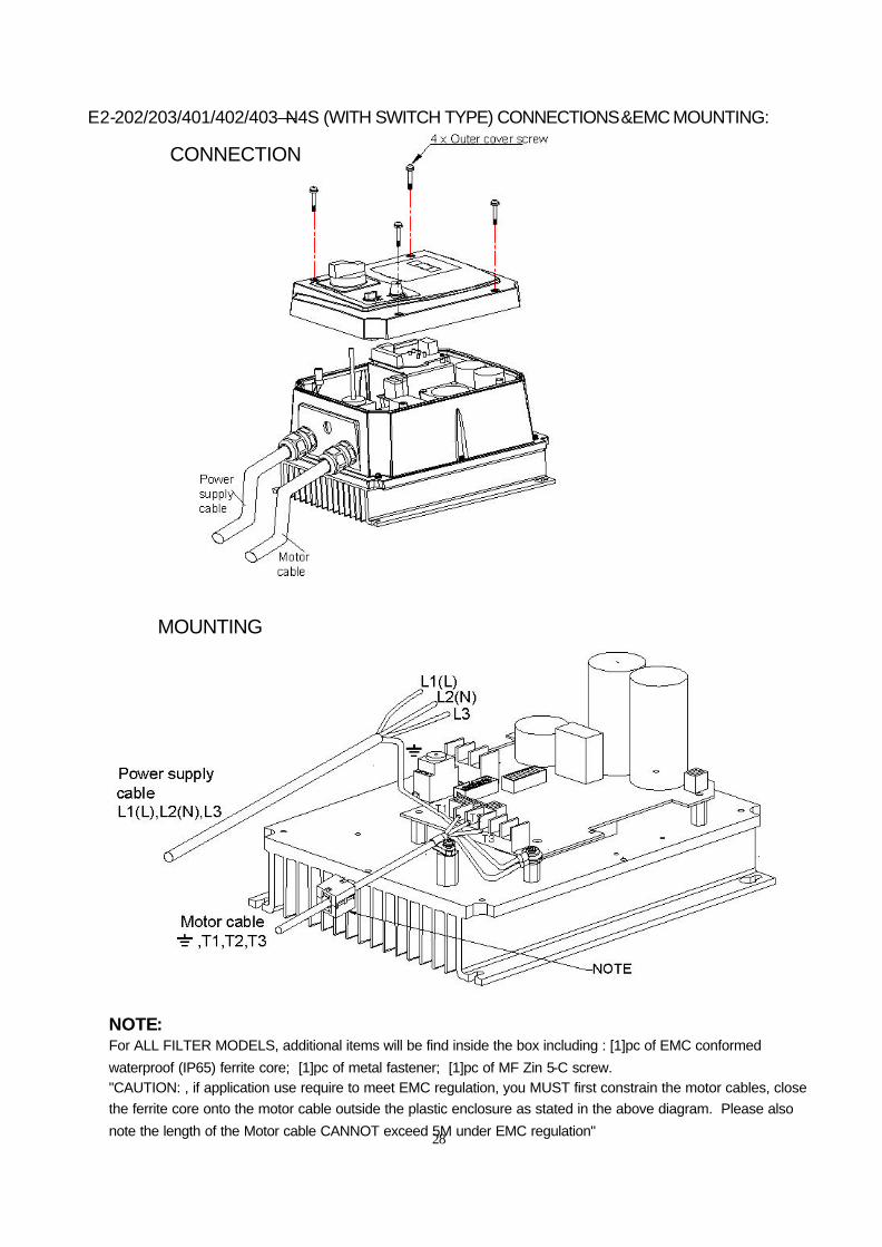
E2-202/203/401/402/403—N4S (WITH SWITCH TYPE) CONNECTIONS&EMC MOUNTING:
CONNECTION
MOUNTING
NOTE: For ALL FILTER MODELS, additional items will be find inside the box including : [1]pc of EMC conformed waterproof (IP65) ferrite core; [1]pc of metal fastener; [1]pc of MF Zin 5-C screw. "CAUTION: , if application use require to meet EMC regulation, you MUST first constrain the motor cables, close the ferrite core onto the motor cable outside the plastic enclosure as stated in the above diagram. Please also note the length of the Motor cable CANNOT exceed 5M under EMC regulation"
29
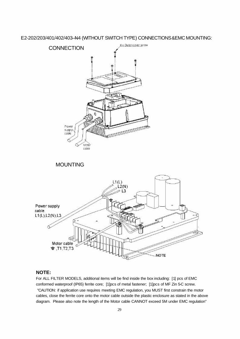
E2-202/203/401/402/403—N4 (WITHOUT SWITCH TYPE) CONNECTIONS&EMC MOUNTING:
CONNECTION
MOUNTING
NOTE: For ALL FILTER MODELS, additional items will be find inside the box including: [1] pcs of EMC conformed waterproof (IP65) ferrite core; [1]pcs of metal fastener; [1]pcs of MF Zin 5-C screw. "CAUTION: if application use requires meeting EMC regulation, you MUST first constrain the motor cables, close the ferrite core onto the motor cable outside the plastic enclosure as stated in the above diagram. Please also note the length of the Motor cable CANNOT exceed 5M under EMC regulation"
30
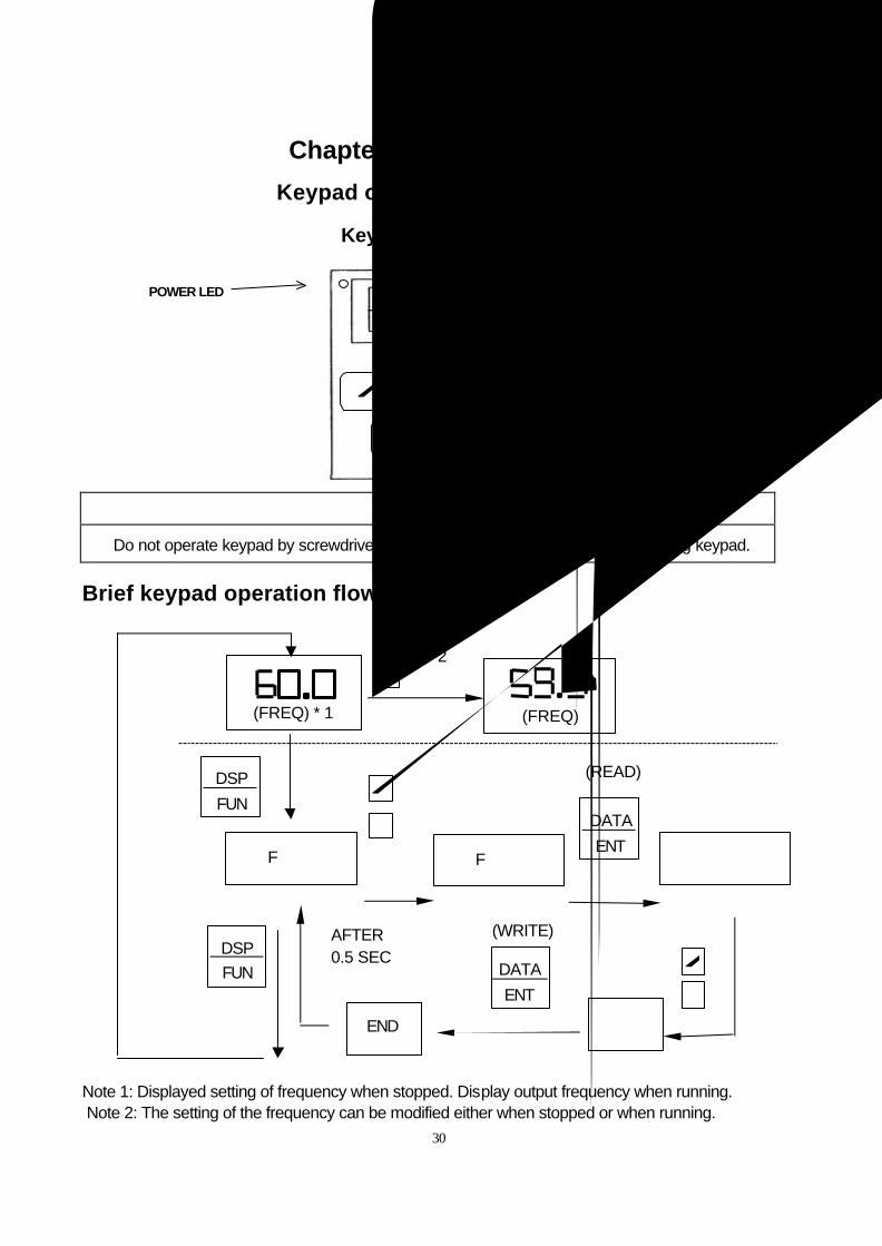
Chapter 3 Software Index
Keypad operating instructions
Keypad Description
CAUTION Do not operate keypad by screwdriver or other sharp-ended tool to avoid damaging keypad.
Brief keypad operation flowchart
Note 1: Displayed setting of frequency when stopped. Display output frequency when running. Note 2: The setting of the frequency can be modified either when stopped or when running.
(FREQ) * 1
(FREQ)
RESET
DATA ENT
RUN S T O P
DSP FUN
POWER LED
F ××
DSP FUN
DSP FUN
F ×× ×××
DATA ENT
(READ)
END ×××
DATA ENT
(WRITE) AFTER 0.5 SEC
* 2
31
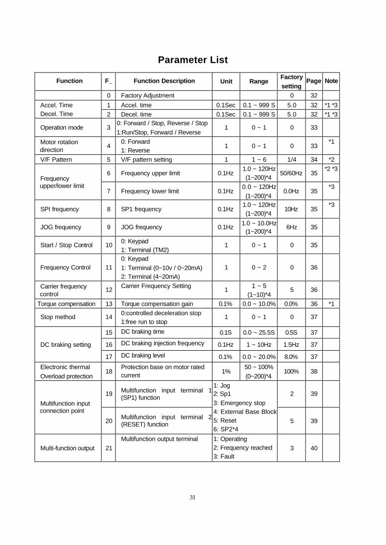
Parameter List
Function F_ Function Description Unit Range Factory
setting Page Note
0 Factory Adjustment 0 32 1 Accel. time 0.1Sec 0.1 ~ 999 S 5.0 32 *1 *3 Accel. Time
Decel. Time 2 Decel. time 0.1Sec 0.1 ~ 999 S 5.0 32 *1 *3
Operation mode 3 0: Forward / Stop, Reverse / Stop 1:Run/Stop, Forward / Reverse
1 0 ~ 1 0 33
Motor rotation direction 4
0: Forward 1: Reverse
1 0 ~ 1 0 33 *1
V/F Pattern 5 V/F pattern setting 1 1 ~ 6 1/4 34 *2
6 Frequency upper limit 0.1Hz 1.0 ~ 120Hz (1~200)*4
50/60Hz 35 *2 *3
Frequency upper/lower limit
7 Frequency lower limit 0.1Hz 0.0 ~ 120Hz (1~200)*4
0.0Hz 35 *3
SPI frequency 8 SP1 frequency 0.1Hz 1.0 ~ 120Hz (1~200)*4
10Hz 35 *3
JOG frequency 9 JOG frequency 0.1Hz 1.0 ~ 10.0Hz (1~200)*4
6Hz 35
Start / Stop Control 10 0: Keypad 1: Terminal (TM2)
1 0 ~ 1 0 35
Frequency Control 11 0: Keypad 1: Terminal (0~10v / 0~20mA) 2: Terminal (4~20mA)
1 0 ~ 2 0 36
Carrier frequency control
12 Carrier Frequency Setting 1 1 ~ 5 (1~10)*4
5 36
Torque compensation 13 Torque compensation gain 0.1% 0.0 ~ 10.0% 0.0% 36 *1
Stop method 14 0:controlled deceleration stop 1:free run to stop
1 0 ~ 1 0 37
15 DC braking time 0.1S 0.0 ~ 25.5S 0.5S 37
16 DC braking injection frequency 0.1Hz 1 ~ 10Hz 1.5Hz 37 DC braking setting
17 DC braking level 0.1% 0.0 ~ 20.0% 8.0% 37
Electronic thermal Overload protection
18 Protection base on motor rated current 1%
50 ~ 100% (0~200)*4
100% 38
19 Multifunction input terminal 1 (SP1) function 2 39
Multifunction input connection point
20 Multifunction input terminal 2 (RESET) function
1: Jog 2: Sp1 3: Emergency stop 4: External Base Block 5: Reset 6: SP2*4
5 39
Multi-function output 21 Multifunction output terminal 1: Operating
2: Frequency reached 3: Fault
3 40
32
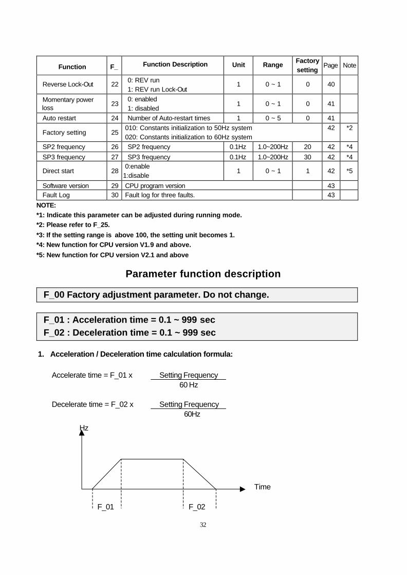
Function F_ Function Description Unit Range Factory setting
Page Note
Reverse Lock-Out 22 0: REV run 1: REV run Lock-Out
1 0 ~ 1 0 40
Momentary power loss 23
0: enabled 1: disabled
1 0 ~ 1 0 41
Auto restart 24 Number of Auto-restart times 1 0 ~ 5 0 41
Factory setting 25 010: Constants initialization to 50Hz system 020: Constants initialization to 60Hz system
42 *2
SP2 frequency 26 SP2 frequency 0.1Hz 1.0~200Hz 20 42 *4 SP3 frequency 27 SP3 frequency 0.1Hz 1.0~200Hz 30 42 *4
Direct start 28 0:enable 1:disable
1 0 ~ 1 1 42 *5
Software version 29 CPU program version 43 Fault Log 30 Fault log for three faults. 43
NOTE:
*1: Indicate this parameter can be adjusted during running mode.
*2: Please refer to F_25.
*3: If the setting range is above 100, the setting unit becomes 1.
*4: New function for CPU version V1.9 and above.
*5: New function for CPU version V2.1 and above
Parameter function description
F_00 Factory adjustment parameter. Do not change.
F_01 : Acceleration time = 0.1 ~ 999 sec F_02 : Deceleration time = 0.1 ~ 999 sec
1. Acceleration / Deceleration time calculation formula:
Setting Frequency Accelerate time = F_01 x
60 Hz
Setting Frequency Decelerate time = F_02 x 60Hz
F_01 F_02
Hz
Time
33
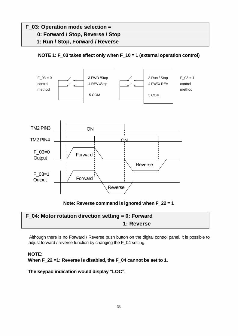
F_03: Operation mode selection = 0: Forward / Stop, Reverse / Stop 1: Run / Stop, Forward / Reverse
NOTE 1: F_03 takes effect only when F_10 = 1 (external operation control)
TM2 PIN3
TM2 PIN4
Note: Reverse command is ignored when F_22 = 1
F_04: Motor rotation direction setting = 0: Forward 1: Reverse
Although there is no Forward / Reverse push button on the digital control panel, it is possible to adjust forward / reverse function by changing the F_04 setting.
NOTE: When F_22 =1: Reverse is disabled, the F_04 cannot be set to 1. The keypad indication would display “LOC”.
F_03 = 0
control
method
F_03 = 1
control
method
3 FWD /Stop
4 REV /Stop
3 Run / Stop
4 FWD/ REV
5 COM 5 COM
Forward
F_03=1 Output
ON
ON
Forward
Reverse
Reverse
F_03=0 Output
34
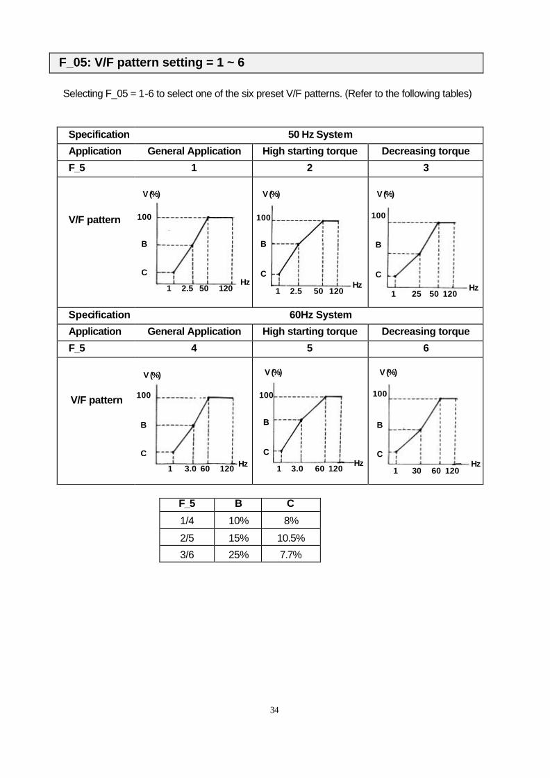
F_05: V/F pattern setting = 1 ~ 6
Selecting F_05 = 1-6 to select one of the six preset V/F patterns. (Refer to the following tables)
Specification 50 Hz System
Application General Application High starting torque Decreasing torque
F_5 1 2 3 V/F pattern
Specification 60Hz System
Application General Application High starting torque Decreasing torque
F_5 4 5 6
V/F pattern
F_5 B C
1/4 10% 8%
2/5 15% 10.5%
3/6 25% 7.7%
V (%) V (%) V (%)
V (%) V (%) V (%)
100
B
C
100
B
C
100
B
C
100
B
C
100
B
C
100
B
C
1 2.5 50 120 1 25 50 120 1 2.5 50 120
1 3.0 60 120 1 3.0 60 120 1 30 60 120
Hz Hz Hz
Hz Hz Hz
35
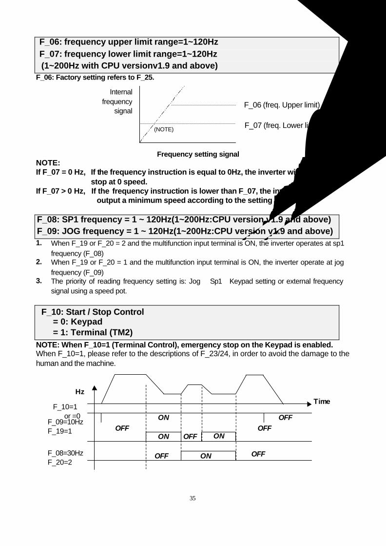
F_06: frequency upper limit range=1~120Hz F_07: frequency lower limit range=1~120Hz (1~200Hz with CPU versionv1.9 and above)
F_06: Factory setting refers to F_25.
NOTE: If F_07 = 0 Hz, If the frequency instruction is equal to 0Hz, the inverter will stop at 0 speed. If F_07 > 0 Hz, If the frequency instruction is lower than F_07, the inverter will output a minimum speed according to the setting in F_07 F_08: SP1 frequency = 1 ~ 120Hz(1~200Hz:CPU version v1.9 and above) F_09: JOG frequency = 1 ~ 120Hz(1~200Hz:CPU version v1.9 and above) 1. When F_19 or F_20 = 2 and the multifunction input terminal is ON, the inverter operates at sp1
frequency (F_08) 2. When F_19 or F_20 = 1 and the multifunction input terminal is ON, the inverter operate at jog
frequency (F_09) 3. The priority of reading frequency setting is: Jog→ Sp1→Keypad setting or external frequency
signal using a speed pot.
F_10: Start / Stop Control = 0: Keypad = 1: Terminal (TM2)
NOTE: When F_10=1 (Terminal Control), emergency stop on the Keypad is enabled. When F_10=1, please refer to the descriptions of F_23/24, in order to avoid the damage to the human and the machine.
Internal frequency
signal
(NOTE)
Frequency setting signal
F_06 (freq. Upper limit) F_07 (freq. Lower limit)
Time Hz
F_10=1 or =0
F_09=10Hz F_19=1
F_08=30Hz F_20=2
ON OFF OFF
ON OFF ON OFF
OFF ON OFF
36
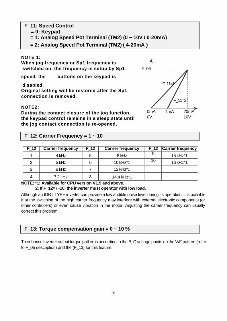
F_11: Speed Control = 0: Keypad = 1: Analog Speed Pot Terminal (TM2) (0 ~ 10V / 0-20mA) = 2: Analog Speed Pot Terminal (TM2) ( 4-20mA )
NOTE 1: When jog frequency or Sp1 frequency is switched on, the frequency is setup by Sp1
speed, the buttons on the keypad is
disabled. Original setting will be restored after the Sp1 connection is removed. NOTE2: During the contact closure of the jog function, the keypad control remains in a sleep state until the jog contact connection is re-opened.
F_12: Carrier Frequency = 1 ~ 10
F_12 Carrier frequency F_12 Carrier frequency F_12 Carrier frequency
1 4 kHz 5 8 kHz 9 15 kHz*1
2 5 kHz 6 10 kHz*1 10 16 kHz*1
3 6 kHz 7 12 kHz*1
4 7.2 kHz 8 14.4 kHz*1 NOTE: *1: Available for CPU version V1.9 and above. 2: If F_12=7~10, the inverter must operator with low load. Although an IGBT TYPE inverter can provide a low audible noise level during its operation, it is possible that the switching of the high carrier frequency may interfere with external electronic components (or other controllers) or even cause vibration in the motor. Adjusting the carrier frequency can usually correct this problem.
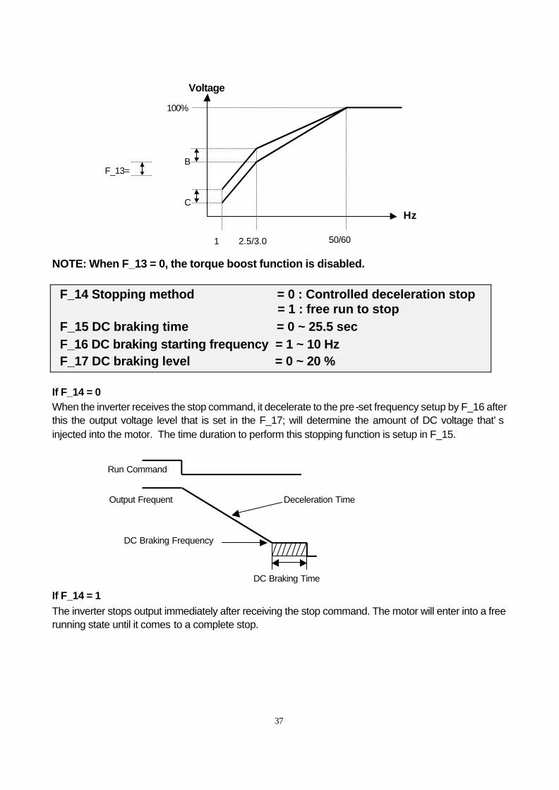
F_13: Torque compensation gain = 0 ~ 10 % To enhance Inverter output torque patt erns according to the B, C voltage points on the V/F pattern (refer to F_05 description) and the (F_13) for this feature.
F_06
0mA 0V
4mA 20mA 10V
F_11=1
F_11=2
37
NOTE: When F_13 = 0, the torque boost function is disabled.
F_14 Stopping method = 0 : Controlled deceleration stop = 1 : free run to stop
F_15 DC braking time = 0 ~ 25.5 sec F_16 DC braking starting frequency = 1 ~ 10 Hz F_17 DC braking level = 0 ~ 20 %
If F_14 = 0 When the inverter receives the stop command, it decelerate to the pre-set frequency setup by F_16 after this the output voltage level that is set in the F_17; will determine the amount of DC voltage that’s injected into the motor. The time duration to perform this stopping function is setup in F_15. If F_14 = 1
The inverter stops output immediately after receiving the stop command. The motor will enter into a free running state until it comes to a complete stop.
1 2.5/3.0 50/60
Hz
F_13= B
C
100%
Voltage
Run Command
Output Frequent Deceleration Time
DC Braking Frequency
DC Braking Time
38
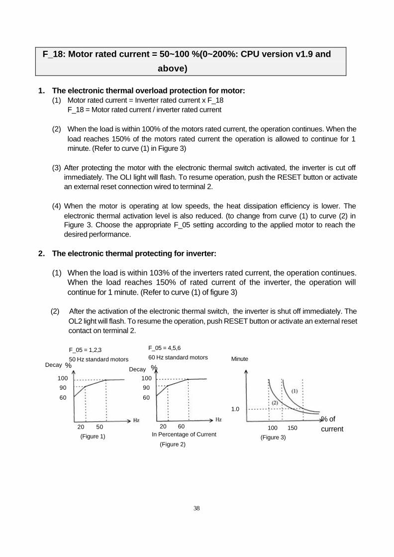
F_18: Motor rated current = 50~100 %(0~200%: CPU version v1.9 and
above) 1. The electronic thermal overload protection for motor:
(1) Motor rated current = Inverter rated current x F_18 F_18 = Motor rated current / inverter rated current
(2) When the load is within 100% of the motors rated current, the operation continues. When the
load reaches 150% of the motors rated current the operation is allowed to continue for 1 minute. (Refer to curve (1) in Figure 3)
(3) After protecting the motor with the electronic thermal switch activated, the inverter is cut off
immediately. The OLI light will flash. To resume operation, push the RESET button or activate an external reset connection wired to terminal 2.
(4) When the motor is operating at low speeds, the heat dissipation efficiency is lower. The
electronic thermal activation level is also reduced. (to change from curve (1) to curve (2) in Figure 3. Choose the appropriate F_05 setting according to the applied motor to reach the desired performance.
2. The electronic thermal protecting for inverter:
(1) When the load is within 103% of the inverters rated current, the operation continues.
When the load reaches 150% of rated current of the inverter, the operation will continue for 1 minute. (Refer to curve (1) of figure 3)
(2) After the activation of the electronic thermal switch, the inverter is shut off immediately. The
OL2 light will flash. To resume the operation, push RESET button or activate an external reset contact on terminal 2.
F_05 = 1,2,3
50 Hz standard motors %
F_05 = 4,5,6
60 Hz standard motors
100
90
60
100
90
60
Decay Minute
20 50
(Figure 1)
20 60 100 150
(Figure 3)
In Percentage of Current
(Figure 2)
1.0
Decay
%
% of current
39
F_19: Multifunctional input terminal 1 function = 1~ 5(1~6:CPU version v1.9 and above) F_20: Multifunctional input terminal 2 function = 1~ 5(1~6:CPU version v1.9 and above)
1. F_19=1 or F_20 =1: JOG control (refer to F_09) 2. F_19, F_20 =2 or 6 Multi-speed control: F_19=2 & F_20=6:
TM2 SP1 Terminal TM2 RESET Terminal Output frequency
ON OFF F_08
OFF ON F_26
ON ON F_27
F_19=6 ﹠F_20=2:
TM2 SP1 Terminal TM2 RESET Terminal Output frequency
ON OFF F_26
OFF ON F_08
ON ON F_27
NOTE: F_19,F_20=2 or 6 are new function for CPU version v1.9 and above. 3. F_19, F_20 =3: External emergency stop
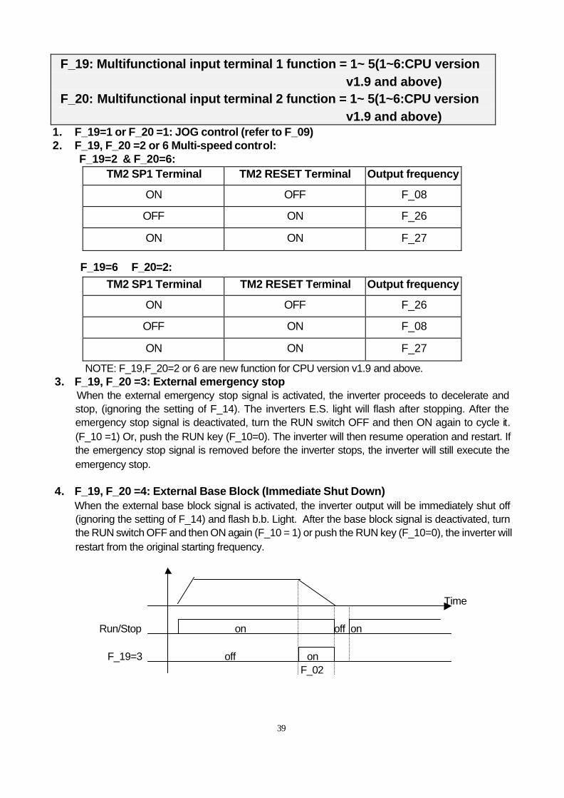
When the external emergency stop signal is activated, the inverter proceeds to decelerate and stop, (ignoring the setting of F_14). The inverters E.S. light will flash after stopping. After the emergency stop signal is deactivated, turn the RUN switch OFF and then ON again to cycle it. (F_10 =1) Or, push the RUN key (F_10=0). The inverter will then resume operation and restart. If the emergency stop signal is removed before the inverter stops, the inverter will still execute the emergency stop.
4. F_19, F_20 =4: External Base Block (Immediate Shut Down) When the external base block signal is activated, the inverter output will be immediately shut off (ignoring the setting of F_14) and flash b.b. Light. After the base block signal is deactivated, turn the RUN switch OFF and then ON again (F_10 = 1) or push the RUN key (F_10=0), the inverter will restart from the original starting frequency.
Time Run/Stop on off on F_19=3 off on F_02
40
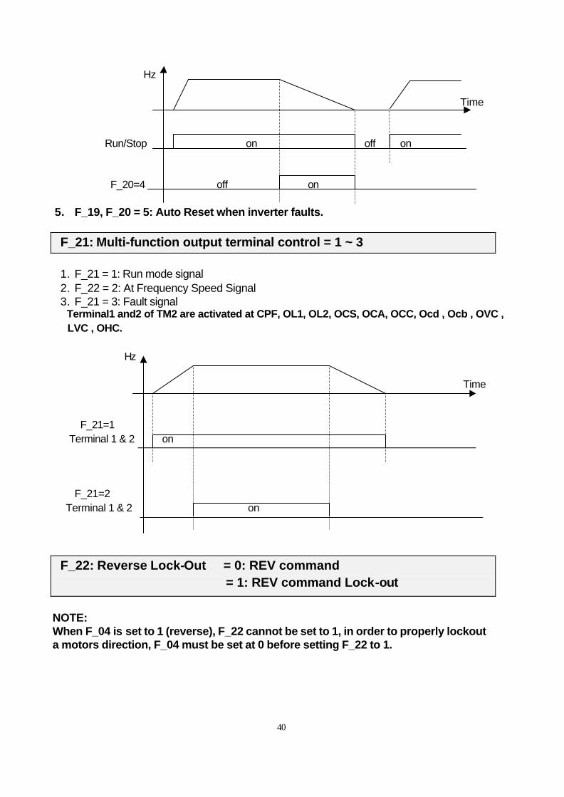
Hz Time Run/Stop on off on F_20=4 off on 5. F_19, F_20 = 5: Auto Reset when inverter faults.
F_21: Multi-function output terminal control = 1 ~ 3
1. F_21 = 1: Run mode signal 2. F_22 = 2: At Frequency Speed Signal 3. F_21 = 3: Fault signal
Terminal1 and2 of TM2 are activated at CPF, OL1, OL2, OCS, OCA, OCC, Ocd , Ocb , OVC , LVC , OHC.
Hz Time F_21=1 Terminal 1 & 2 on F_21=2 Terminal 1 & 2 on
F_22: Reverse Lock-Out = 0: REV command = 1: REV command Lock-out
NOTE: When F_04 is set to 1 (reverse), F_22 cannot be set to 1, in order to properly lockout a motors direction, F_04 must be set at 0 before setting F_22 to 1.
41
F_23: Auto-restart after momentary power loss
=0: auto-restart enabled =1: auto-restart disabled
1. When the AC power supply is temporary below low voltage protection levels because of power
company issues or encountering large current loading in the same power supply system, the inverter will stop its output immediately. If the power source resumes within 2 seconds, the inverter can restart by using its speed search program.
2. When F_23=0:
(1) If the momentary power loss is less than 2 seconds, the inverter resume operation automatically via speed search at 0.5 seconds after power up. The number of auto-restart times is not limited by F_24.
(2) If the momentary power loss is long, the operation of the inverter is based on the setup of F_10 and the condition of external switch.
(3) If the time of momentary loss is between the above two, whether the inverter will auto-restart depends on F_24:
F_24=0: auto-restart disabled. F_24=1~5: auto-restart enabled 1~5 times.
3. When F_23=1,
(1) Power up after momentary power loss, the inverter will not start. Even under F_24>0. (2) If the momentary power loss is long, the inverter must be restart manually. The operation of the
inverter is based on the setup of F_10 and the condition of external switch.
4. When restart the inverter, the operation of the inverter is based on the setup of F_10 and the condition of external switches (FWD/REV button). (1) When F_10=0, the inverter will not start after restart. (2) When F_10=1 and the external switch (FWD/REV button) is OFF, the inverter will not start after
restart. (3) When F_10=1 and the external switch (FWD/REV button) is ON, the inverter will start
automatically after restart. Attention: Base on safety reason, please turn off the external switch (FWD/REV button) after power loss to avoid possible damage to the machine and the human body after sudden regeneration of power.
F_24: Number of Auto-restart times = 0~5
1. When F_24=0, the inverter will not auto-restart after a malfunction break away from operation. (Except for momentary power loss, please refer to F_23 for details)
2. When F_24=1~5: the inverter will resume operation via speed search at 0.5 second under
auto-restart after malfunction break away. (Except for momentary power loss, please refer to F_23 for details).
3. When the inverter is set to deceleration or DC breaking, the transient restart procedure is not
performed.
42
4. If either of following situations should develop, the auto restart times will be reset:
(1) No additional malfunction (in operation or stop) occurs within 10 minutes. (2) Press RESET button.
F_25: Return to Factory Pre-Settings = 010: Constants initialization to 50Hz system = 020: Constants initialization to 60Hz system
1. When F_25 is set to 010, all parameters are restored to factory settings. The settings of F_05 =1
and F_06 = 50. F_25 is restored back to 000 after the reset process is complete. (50Hz operation) 2. When F_25 is set to 020, all parameters are restored to factory settings. The settings of F_05 =4 and
F_06 = 60. F_25 is restored back to 000 after the reset process is complete. (60Hz operation)
F_26: SP2(1~200Hz) , Multi-speed2 (Reference to F_19 ﹠F_20)
F_27: SP3(1~200Hz) , Multi-speed3 (Reference to F_19 ﹠F_20)
F_28: Direct start
= 0 : Direct start enable when remote Run command on
= 1 : Direct start disable when remote Run command on
(CPU version V2.1 and above) When F_28 = 1 and control mode is remote control (F_10 = 1), Inverter can not start if RUN switch is ON when power is engaged, Must be turned the RUN switch OFF and turned ON again, Then Inverter can start.
43
F_29: CPU program version
F_30: Last three faults 1. Last three faults: indicate the sequence of the occurrence of malfunctions by the location of decimal
point. x.xx indicates a recently happened malfunction. xx.x indicates the last malfunction that happened. xxx. Indicates the earliest malfunction in the record.
2. After entering the F_30 function, the x.xx trip record will be displayed first. After that, press button
and you can read activity in a chronological order. xx.xàxxx.àx.xx à,,, consecutively. 3. After entering F_30 function, if the RESET button is pressed, the trip record will be cleared.
Indication display -.--, --.-, and ---. 4. When the content of trip indicates O.CC, it will indicate the latest trip code is OC-C and so on.
44
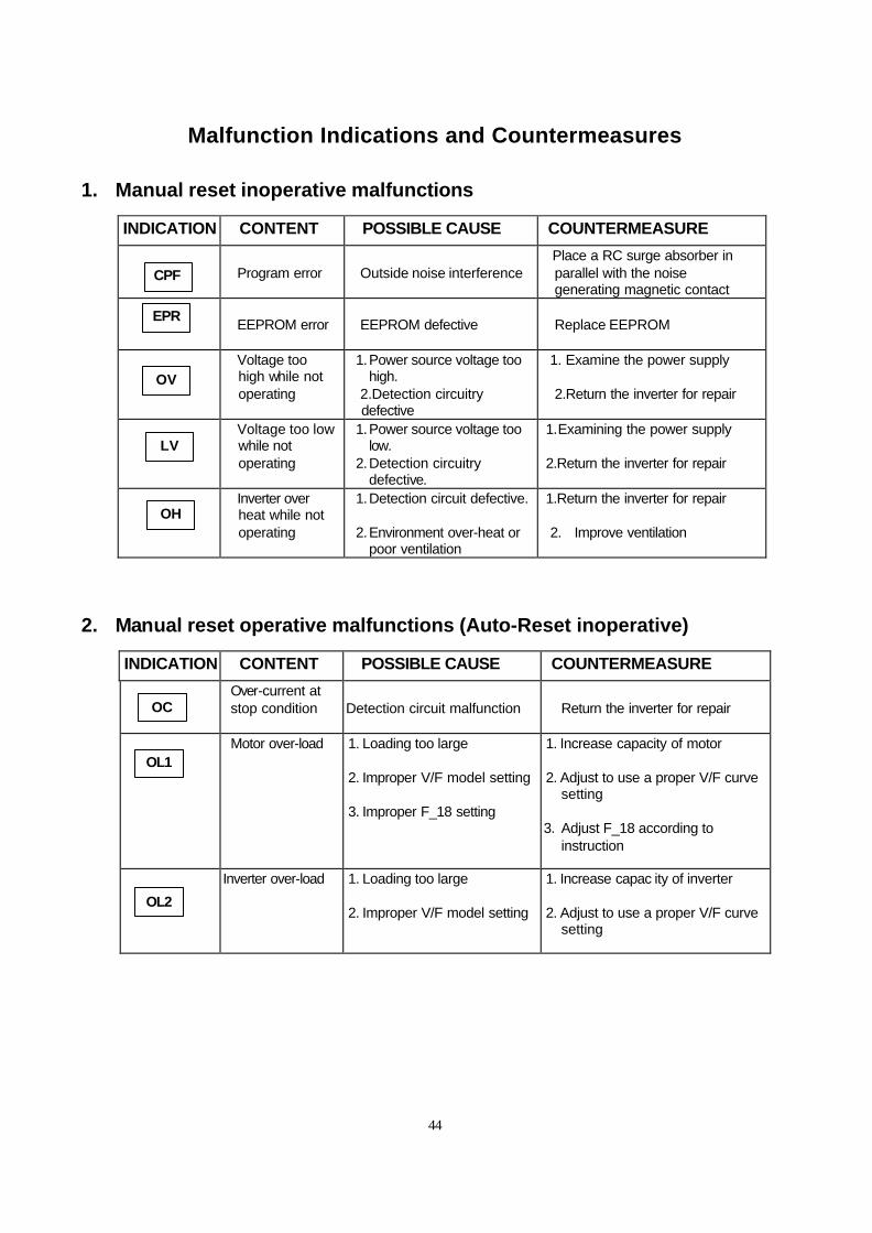
Malfunction Indications and Countermeasures
1. Manual reset inoperative malfunctions
INDICATION CONTENT POSSIBLE CAUSE COUNTERMEASURE
Program error
Outside noise interference
Place a RC surge absorber in parallel with the noise generating magnetic contact
EEPROM error
EEPROM defective
Replace EEPROM
Voltage too high while not operating
1. Power source voltage too high.
2.Detection circuitry defective
1. Examine the power supply 2.Return the inverter for repair
Voltage too low while not operating
1. Power source voltage too low.
2. Detection circuitry defective.
1. Examining the power supply 2.Return the inverter for repair
Inverter over heat while not operating
1. Detection circuit defective. 2. Environment over-heat or
poor ventilation
1.Return the inverter for repair 2. Improve ventilation
2. Manual reset operative malfunctions (Auto-Reset inoperative)
INDICATION CONTENT POSSIBLE CAUSE COUNTERMEASURE
Over-current at stop condition
Detection circuit malfunction
Return the inverter for repair
Motor over-load
1. Loading too large 2. Improper V/F model setting 3. Improper F_18 setting
1. Increase capacity of motor 2. Adjust to use a proper V/F curve
setting 3. Adjust F_18 according to
instruction
Inverter over-load
1. Loading too large 2. Improper V/F model setting
1. Increase capac ity of inverter 2. Adjust to use a proper V/F curve
setting
CPF
EPR
OV
LV
OH
OC
OL1
OL2
45
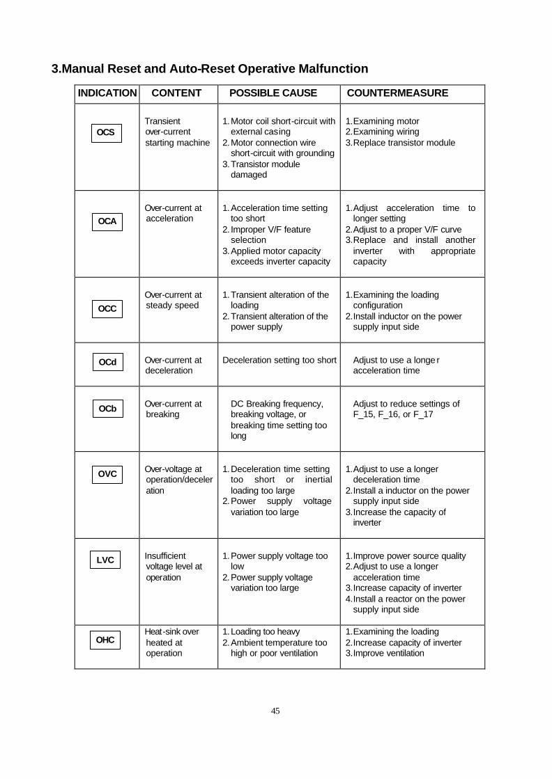
3.Manual Reset and Auto-Reset Operative Malfunction
INDICATION CONTENT POSSIBLE CAUSE COUNTERMEASURE
Transient over-current starting machine
1. Motor coil short-circuit with
external casing 2. Motor connection wire
short-circuit with grounding 3. Transistor module
damaged
1. Examining motor 2. Examining wiring 3. Replace transistor module
Over-current at acceleration
1. Acceleration time setting
too short 2. Improper V/F feature
selection 3. Applied motor capacity
exceeds inverter capacity
1. Adjust acceleration time to
longer setting 2. Adjust to a proper V/F curve 3. Replace and install another
inverter with appropriate capacity
Over-current at steady speed
1. Transient alteration of the
loading 2. Transient alteration of the
power supply
1. Examining the loading
configuration 2. Install inductor on the power
supply input side
Over-current at deceleration
Deceleration setting too short
Adjust to use a longe r acceleration time
Over-current at breaking
DC Breaking frequency, breaking voltage, or breaking time setting too long
Adjust to reduce settings of F_15, F_16, or F_17
Over-voltage at operation/deceleration
1. Deceleration time setting
too short or inertial loading too large
2. Power supply voltage variation too large
1. Adjust to use a longer
deceleration time 2. Install a inductor on the power
supply input side 3. Increase the capacity of
inverter
Insufficient voltage level at operation
1. Power supply voltage too
low 2. Power supply voltage
variation too large
1. Improve power source quality 2. Adjust to use a longer
acceleration time 3. Increase capacity of inverter 4. Install a reactor on the power
supply input side
Heat-sink over heated at operation
1. Loading too heavy 2. Ambient temperature too
high or poor ventilation
1. Examining the loading 2. Increase capacity of inverter 3. Improve ventilation
OCS
OCA
OCC
OCd
OCb
OVC
LVC
OHC
46
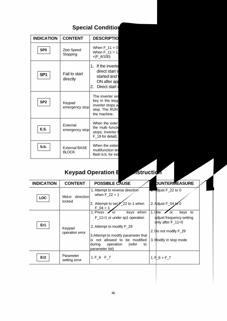
Special Condition Description
INDICATION CONTENT DESCRIPTION
Zero Speed Stopping
When F_11 = 0, F_7= 0 and frequency setting < 1 Hz When F_11 = 1, F_7<(F_6/100), and frequency setting <(F_6/100)
Fail to start
directly
1. If the inverter is set to external operation (F_10 = 1) and
direct start is disabled (F_28 =1), the inverter cannot be started and will flash SP1 when operation switch turned to ON after applying power (see descriptions of F_28).
2. Direct start is possible when F_28 = 0.
Keypad emergency stop
The inverter setup to external operation (F_10=1). If the STOP key in the keypad is pressed at the middle of operation, the inverter stops according the setting in F_14 and flash SP2 after stop. The RUN switch must be turned OFF than ON to restart the machine.
External emergency stop
When the external emergency stop signal is activated through the multi -function input terminal, the inverter decelerates and stops. Inverter flashes E.S. after stops. (Refer to instruction for F_19 for detail).
External BASE BLOCK
When the external BASE BLOCK signal is activated through the multifunction terminal, the inverter stop output immediately and flash b.b. for indication. (Refer to instruction for F_19 for detail)
Keypad Operation Error Instruction
INDICATION CONTENT POSSIBLE CAUSE COUNTERMEASURE
Motor direction locked
1. Attempt to reverse direction when F_22 = 1
2. Attempt to set F_22 to 1 when
F_04 = 1
1. Adjust F_22 to 0 2. Adjust F_04 to 0
Keypad operation error
1. Press or keys when F_11=1 or under sp1 operation
2. Attempt to modify F_29 3.Attempt to modify parameter that is not allowed to be modified during operation (refer to parameter list)
1. Use or keys to adjust frequency setting only after F_11=0
2. Do not modify F_29 3. Modify in stop mode
Parameter setting error
1. F_6≦F_7
1. F_6 > F_7
SP0
LOC
Er1
Er2
E.S.
b.b.
SP2
SP1

47
General Malfunction Examination Method
ABNORMALITY CHECK POINT COUNTERMEASURE
Is the power source voltage delivered to L1, L2 terminal (is the charging indicator illuminated)?
l Check if the power source on.
l Turn power source OFF and then ON again.
l Reconfirm the power voltage level.
Is there voltage output from output terminal T1, T2 and T3?
l Turn power source OFF and then ON again.
Is the motor wired correctly? l Check motor wiring.
Is there any abnormal condition of the inverter?
Motor
Inoperative
Is the forward or reverse instruction loaded?
l Refer to malfunction handling instructions to examine and correct wiring.
Is the analog frequency setting loaded? l Check to see if wiring for analog frequency input signal is correct?
Motor
Inoperative If the operation mode setting correct? l Check if the frequency input setting
voltage is correct?
Is wiring on the output terminals T1, T2 and T3 correct?
l Operate by digital?
Motor operate in opposite direction Is the wiring for the forward and reverse
signals correct? l Wiring should be in accordance with the
U, V, W terminals of motor.
Is the wiring for analog frequency input correct?
l Examining the wiring and correct it.
Is the operation mode setting correct? l Examining the wiring and correct it.
Motor operation
speed fixed
Is the loading too heavy? l Check the Operation panel
Is the specification of motor (poles, voltage) correct?
l Reduce loading
Is the gear ratio correct? l Reconfirm motor specification.
Is the highest output frequency setting correct?
l Reconfirm gear ratio
Motor operation
at speed too high or too low
Is the voltage on motor side reduced extremely?
l Reconfirm highest output frequency
Is the loading too heavy? l Reduce loading variation
Is the loading variation too large? l Increase inverter and motor capacity
Abnormal speed variation at operation
Is the input power source steady and stable?
l Install AC reactor on the power supply input side
48
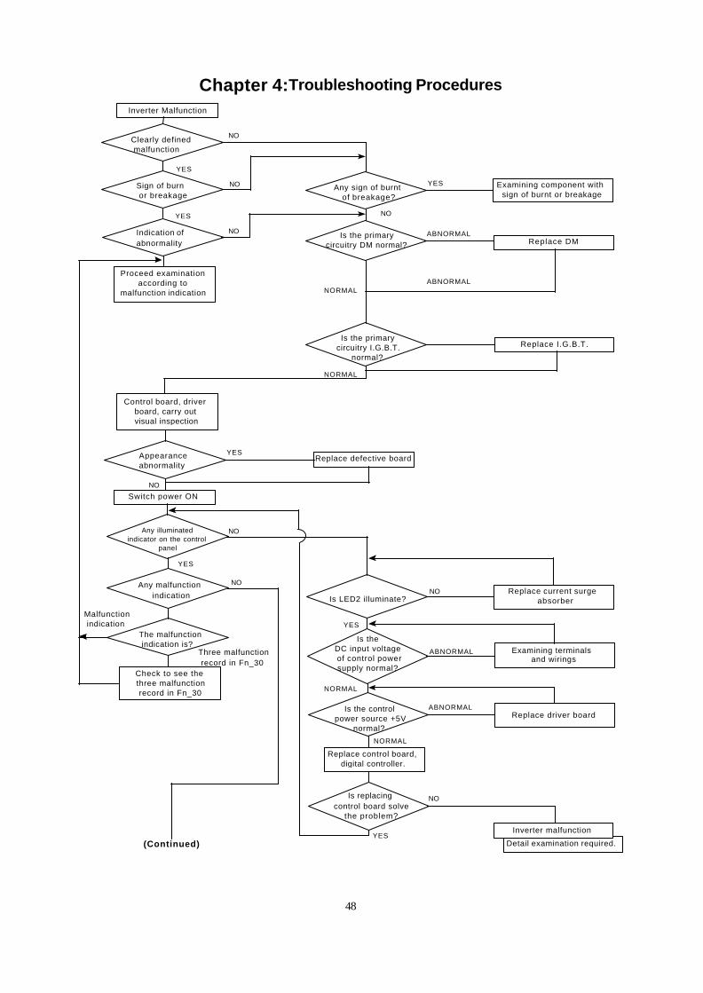
Chapter 4:Troubleshooting Procedures Inverter Malfunction
Clearly defined malfunction
Proceed examinationaccording to
malfunction indication
Control board, driverboard, carry out
visual inspection
Switch power ON
Any illuminatedindicator on the control
panel
Check to see the three malfunction record in Fn_30
Sign of burn or breakage
Indication ofabnormality
Appearanceabnormality
Malfunction indication
Any malfunction indication
Three malfunction record in Fn_30
The malfunction indication is?
Any sign of burnt of breakage?
Is the primarycircuitry DM normal?
Is the primary circuitry I.G.B.T.
normal?
Replace defective board
Is LED2 illuminate?
Is theDC input voltage of control powersupply normal?
Is the control power source +5V
normal?
Replace control board,digital controller.
Is replacing control board solve
the problem?
Examining component withsign of burnt or breakage
Replace DM
Replace I.G.B.T.
Replace current surge absorber
Examining terminalsand wirings
Replace driver board
Detail examination required.
Inverter malfunction
NO
NO
NO
YES
YES
YES
NO
ABNORMAL
NORMAL
YES
NO
NO
NO
YES
NO
ABNORMAL
YES
NORMAL
ABNORMAL
NORMAL
NO
YES(Continued)
ABNORMAL
NORMAL
49
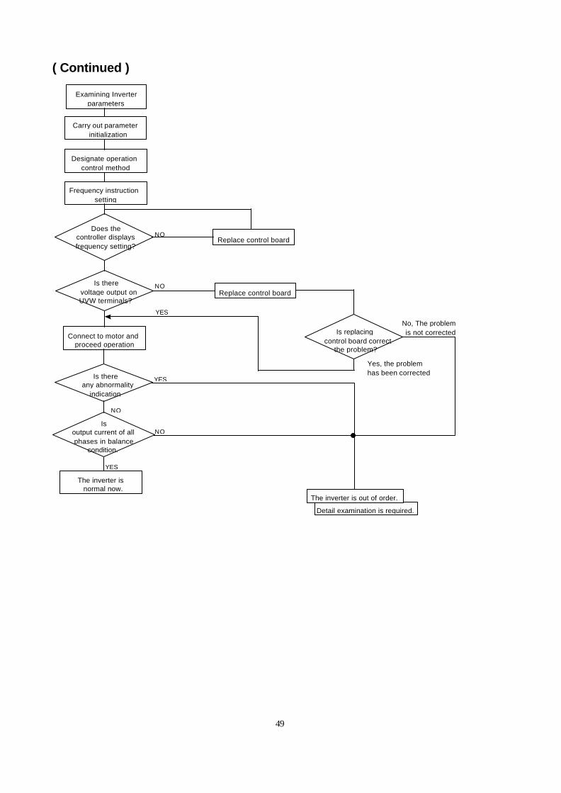
( Continued )
Examining Inverterparameters
Connect to motor andproceed operation
Isoutput current of allphases in balance
condition.
Is there any abnormality
indication
Detail examination is required.
The inverter is out of order.
YES
Carry out parameter initialization
Designate operationcontrol method
Frequency instructionsetting
Does thecontroller displaysfrequency setting?
Is there voltage output onUVW terminals?
The inverter is normal now.
Replace control board
Replace control board
Is replacing control board correct
the problem?
Yes, the problemhas been corrected
No, The problem is not corrected
YES
NO
NO
YES
NO
NO

50
Error handling of malfunction indication of OC.OL
When inverter displaymalfunction indication
OC.OL.
Switch ON power supply
Is the output frequencydisplayed?
Detail examination is required.
Inverter is out of order.
YES
Is the appearancenormal?
Is the primarycircuit I.G.B.T.
normal?
Input operation instruction
Replace I.G.B.T.
Is the currentdetector normal?
NO
YES
NO
ABNORMAL
Is there anymalfunction indication
Input frequency setting
Is there output voltage on UVW
terminals?
Connect motor andproceed with operation.
Is there any malfunctionindication
Is outputcurrent of all phases in
balance condition.
The inverter is normal now.
Replace defective PCB
Replace control board. Replace detector.
Replace control board
Replace control board
Is replacingcontrol board correct this
Problem?
NORMAL
YES
ABNORMAL
NORMAL
NO
YES
YES
NO
NO
YES
YES
NO
YES
51
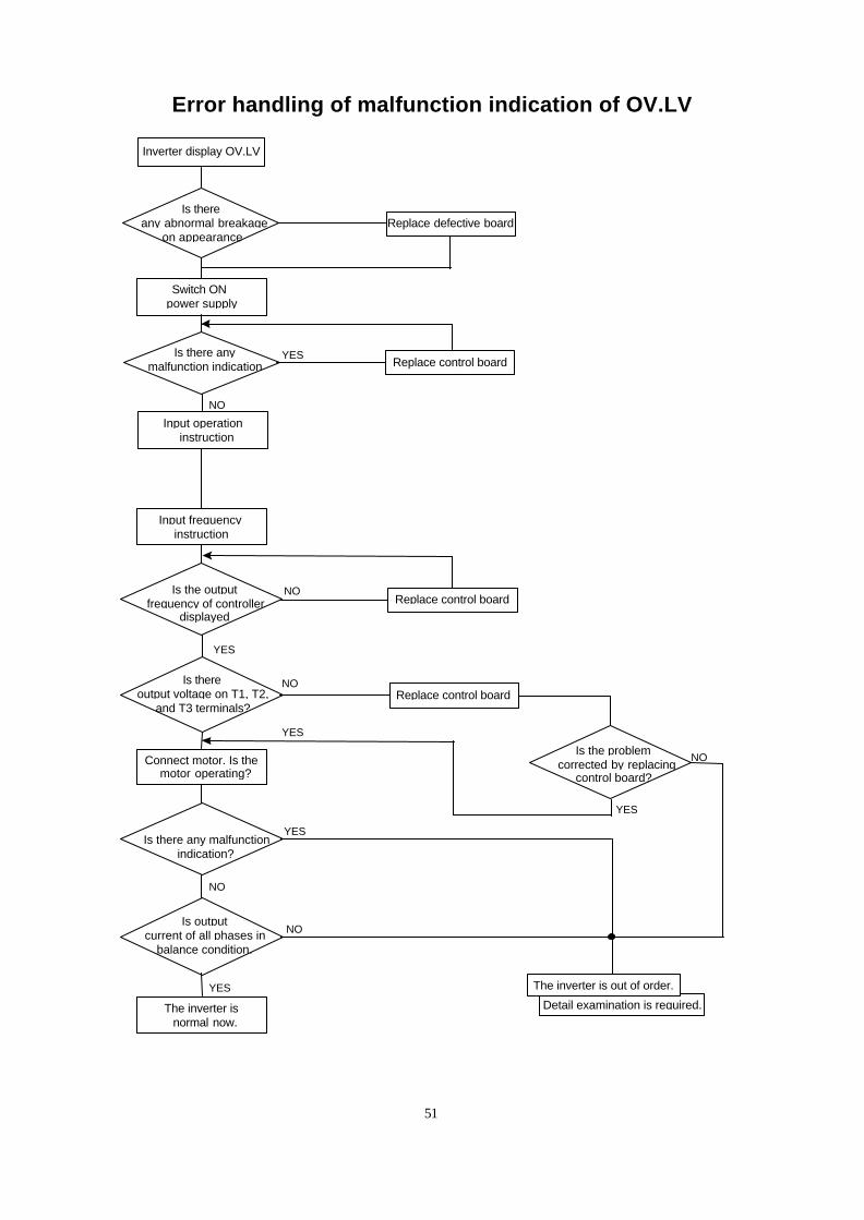
Error handling of malfunction indication of OV.LV
Inverter display OV.LV
Switch ONpower supply
Is the outputfrequency of controller
displayed
Detail examination is required.
The inverter is out of order.
Is there any abnormal breakage
on appearance
Input operation instruction
Replace defective board
NO
NO
Is there anymalfunction indication
Input frequencyinstruction
Is thereoutput voltage on T1, T2,
and T3 terminals?
Connect motor. Is the motor operating?
Is there any malfunctionindication?
Is outputcurrent of all phases in
balance condition.
The inverter is normal now.
Replace control board
Replace control board
Replace control board
Is the problem corrected by replacing
control board?
YES
YES
NO
YES
YES
NO
YES
NO
YES
NO
52
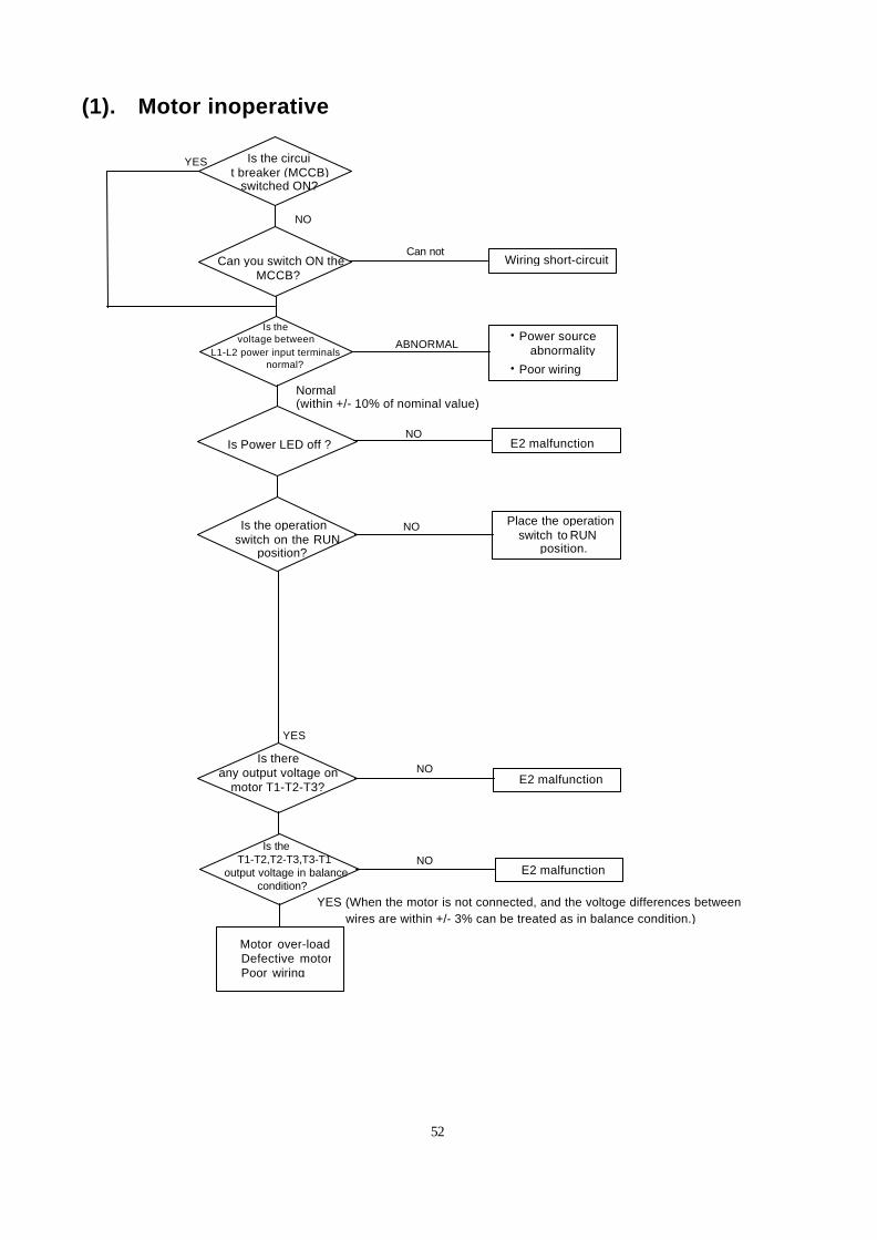
(1). Motor inoperative
Is Power LED off ?
Is the circuit breaker (MCCB)
switched ON?
Wiring short-circuitCan not
Is the operation switch on the RUN
position?
Motor over-load Defective motor Poor wiring
E2 malfunction
E2 malfunction
YES
Can you switch ON theMCCB?
• Power source abnormality
• Poor wiring
Place the operation switch to RUN
position.
Is theT1-T2,T2-T3,T3-T1
output voltage in balancecondition?
ABNORMAL
NO
YES
YES (When the motor is not connected, and the voltoge differences betweenwires are within +/- 3% can be treated as in balance condition.)
Normal(within +/- 10% of nominal value)
NO
NO
Is thevoltage between
L1-L2 power input terminalsnormal?
NO
Is thereany output voltage on
motor T1-T2-T3?
E2 malfunction
NO
53
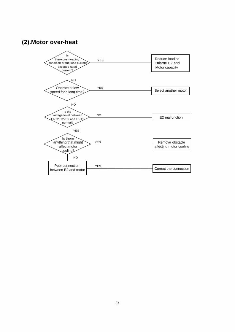
(2).Motor over-heat
Is thereanything that might
affect motorcooling?
Reduce loading Enlarge E2 and
Motor capacity
Is thevoltage level between
T1-T2, T2-T3, and T3-T1normal?
YES
Operate at lowspeed for a long time? Select another motor
Remove obstacleaffecting motor cooling
Correct the connection
NO
YES
YES
E2 malfunction
Poor connectionbetween E2 and motor
Isthere over-loading
condition or the load currentexceeds rated
current?
NO
YES
YES
NO
NO
54
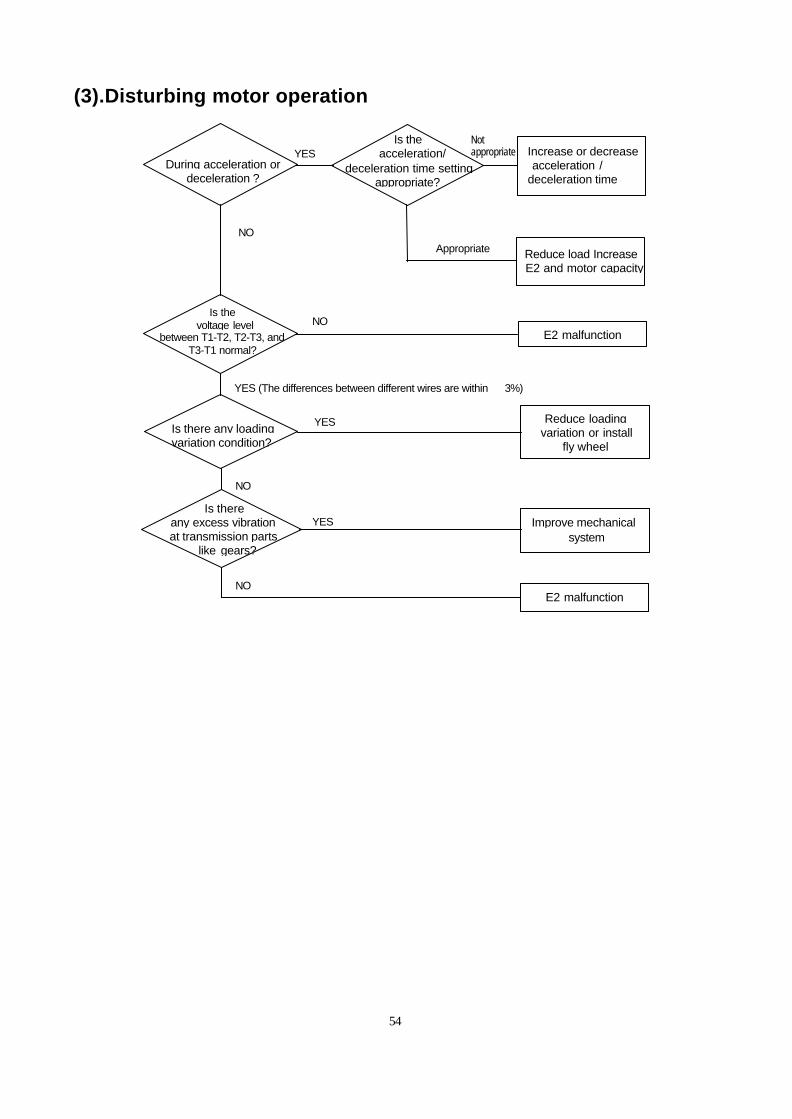
(3).Disturbing motor operation
Is thereany excess vibrationat transmission parts
like gears?
Increase or decrease acceleration /deceleration time
Is there any loadingvariation condition?
YES
Reduce load Increase E2 and motor capacity
Reduce loading variation or install
fly wheel
Improve mechanicalsystem
NO
YES
YES
E2 malfunction
During acceleration ordeceleration ?
NO
Is the voltage level
between T1-T2, T2-T3, andT3-T1 normal?
Is the acceleration/
deceleration time settingappropriate?
E2 malfunction
NO
NO
Notappropriate
Appropriate
YES (The differences between different wires are within ±3%)
55
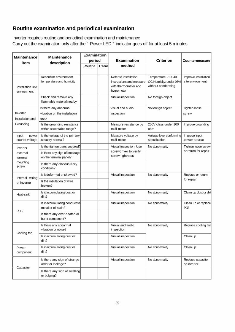
Routine examination and periodical examination
Inverter requires routine and periodical examination and maintenance Carry out the examination only after the “ Power LED ” indicator goes off for at least 5 minutes
Examination
period Maintenance
item
Maintenance
description Routine 1 Year
Examination
method
Criterion
Countermeasure
Reconfirm environment temperature and humidity
Refer to installation instructions and measure with thermometer and hygrometer
Temperature: -10~40 OC Humidity: under 95% without condensing Installation site
environment
Check and remove any flammable material nearby
Visual inspection No foreign object
Improve installation site environment
Is there any abnormal
vibration on the installation
site?
Visual and audio
Inspection
No foreign object Tighten loose
screw Inverter
Installation and
Grounding Is the grounding resistance within acceptable range?
Measure resistance by multi-meter
200V class under 100 ohm
Improve grounding
Input power source voltage
Is the voltage of the primary circuitry normal?
Measure voltage by multi-meter
Voltage level conforming specification
Improve input power source
Is the tighten parts secured?
Is there any sign of breakage on the terminal panel?
Inverter
external terminal mounting screw
Is there any obvious rusty condition?
Visual inspection. Use screwdriver to verify screw tightness
No abnormality
Tighten loose screw or return for repair
Is it deformed or skewed? Internal wiring of inverter Is the insulation of wire
broken?
Visual inspection
No abnormality
Replace or return for repair
Heat-sink Is it accumulating dust or dirt?
Visual inspection No abnormality Clean up dust or dirt
Is it accumulating conductive metal or oil stain?
PCB Is there any over-heated or burnt component?
Visual inspection
No abnormality
Clean up or replace PCB
Is there any abnormal vibration or noise?
Visual and audio inspection
Replace cooling fan
Cooling fan Is it accumulating dust or dirt?
Visual inspection
No abnormality
Clean up
Power component
Is it accumulating dust or dirt?
Visual inspection No abnormality
Clean up
Is there any sign of strange order or leakage?
Capacitor Is there any sign of swelling or bulging?
Visual inspection No abnormality Replace capacitor or inverter
56
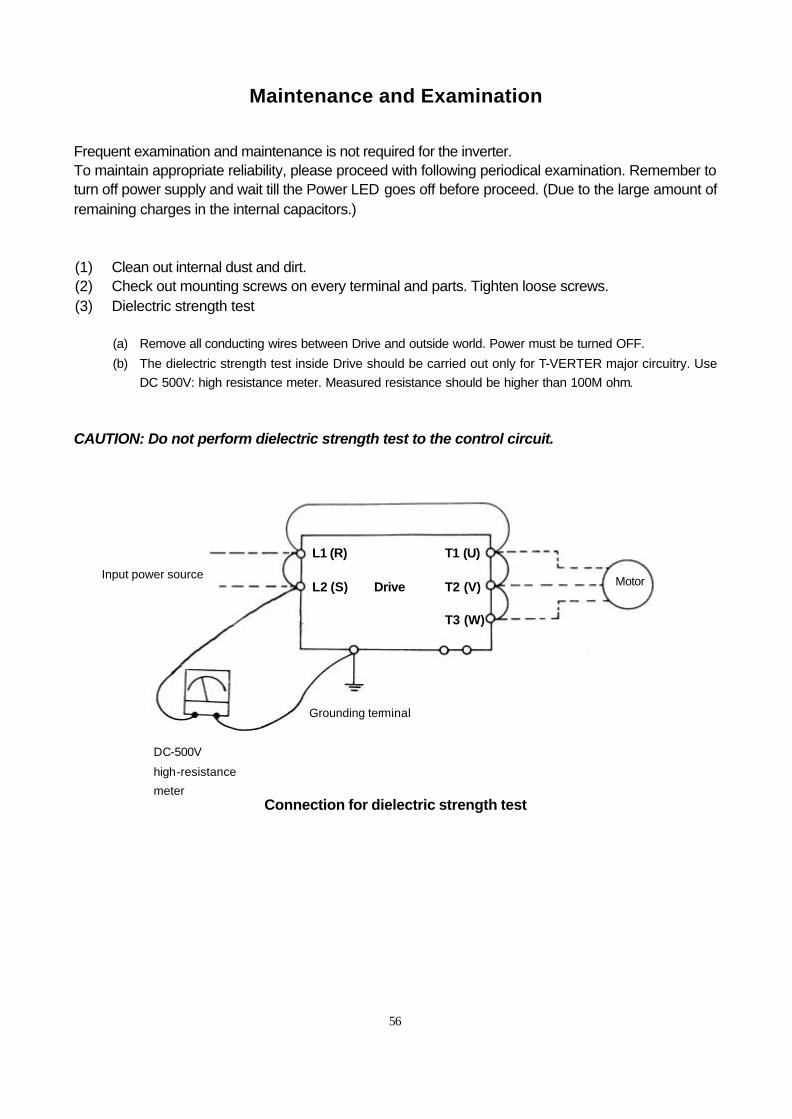
Maintenance and Examination
Frequent examination and maintenance is not required for the inverter. To maintain appropriate reliability, please proceed with following periodical examination. Remember to turn off power supply and wait till the Power LED goes off before proceed. (Due to the large amount of remaining charges in the internal capacitors.) (1) Clean out internal dust and dirt. (2) Check out mounting screws on every terminal and parts. Tighten loose screws. (3) Dielectric strength test
(a) Remove all conducting wires between Drive and outside world. Power must be turned OFF. (b) The dielectric strength test inside Drive should be carried out only for T-VERTER major circuitry. Use
DC 500V: high resistance meter. Measured resistance should be higher than 100M ohm. CAUTION: Do not perform dielectric strength test to the control circuit.
Connection for dielectric strength test
Input power source
DC-500V
high-resistance
meter
Grounding terminal
Motor
L1 (R) T1 (U) L2 (S) Drive T2 (V) T3 (W)
57
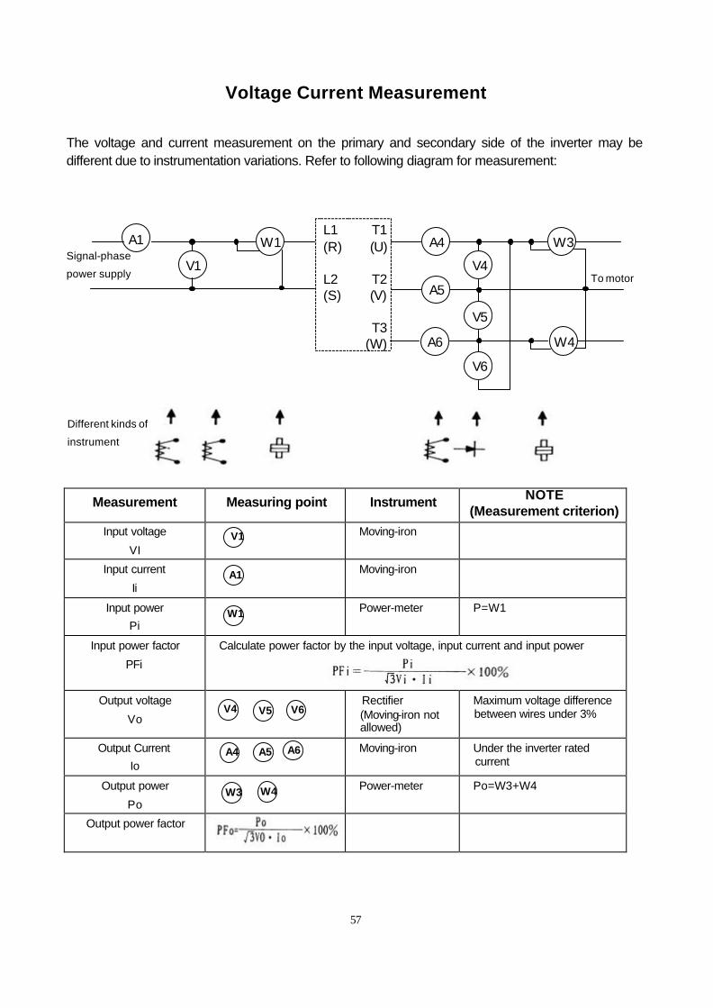
Voltage Current Measurement
The voltage and current measurement on the primary and secondary side of the inverter may be different due to instrumentation variations. Refer to following diagram for measurement:
Measurement Measuring point Instrument NOTE (Measurement criterion)
Input voltage
VI
Moving-iron
Input current
Ii
Moving-iron
Input power Pi
Power-meter P=W1
Input power factor
PFi
Calculate power factor by the input voltage, input current and input power
Output voltage
Vo
Rectifier (Moving-iron not allowed)
Maximum voltage difference between wires under 3%
Output Current Io
Moving-iron Under the inverter rated current
Output power
Po
Power-meter Po=W3+W4
Output power factor
A1
V1
W1 A4
A5
A6
V4
V5
V6
W3
W4
L1 (R) L2 (S)
T1 (U)
T2 (V)
T3
(W)
Signal-phase
power supply
To motor
Different kinds of
instrument
V1
W1
A1
V4 V5 V6
A6 A4 A5
W4 W3
58
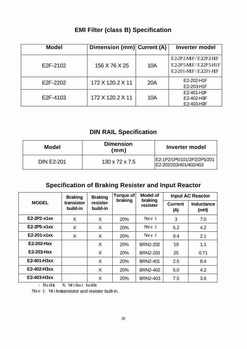
EMI Filter (class B) Specification
Model Dimension (mm) Current (A) Inverter model
E2F-2102 156 X 76 X 25 10A E2-2P2-M1F/E2-2P2-H1F
E2-2P5-M1F/E2-2P5-H1F E2-201-M1F/E2-201-H1F
E2F-2202 172 X 120.2 X 11 20A E2-202-H1F E2-203-H1F
E2F-4103 172 X 120.2 X 11 10A E2-401-H3F E2-402-H3F E2-403-H3F
DIN RAIL Specification
Model Dimension (mm) Inverter model
DIN E2-201 130 x 72 x 7.5 E2-1P2/1P5/101/2P2/2P5/201 E2-202/203/401/402/403
Specification of Braking Resister and Input Reactor
Input AC Reactor MODEL
Braking transistor build-in
Braking resister build-in
Torque of braking
Model of braking resister Current
(A) Inductance
(mH)
E2-2P2-x1xx X X 20% Note 1 3 7.0
E2-2P5-x1xx X X 20% Note 1 5.2 4.2
E2-201-x1xx X X 20% Note 1 9.4 2.1
E2-202-Hxx X 20% BRN2-202 19 1.1
E2-203-Hxx X 20% BRN2-203 25 0.71
E2-401-H3xx X 20% BRN2-401 2.5 8.4
E2-402-H3xx X 20% BRN2-402 5.0 4.2
E2-403-H3xx X 20% BRN2-403 7.5 3.6 : Built-in X: Without built-in
Note 1: Without transistor and resister built-in.
59
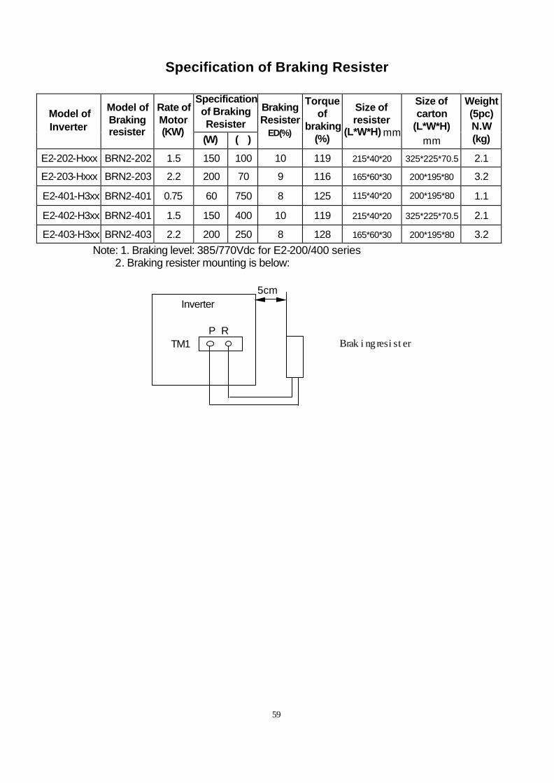
Specification of Braking Resister
Specification of Braking Resister
Model of Inverter
Model of Braking resister
Rate of Motor (KW)
(W) (Ω)
Braking Resister
ED(%)
Torque of
braking (%)
Size of resister
(L*W*H) mm
Size of carton
(L*W*H) mm
Weight (5pc) N.W (kg)
E2-202-Hxxx BRN2-202 1.5 150 100 10 119 215*40*20 325*225*70.5 2.1
E2-203-Hxxx BRN2-203 2.2 200 70 9 116 165*60*30 200*195*80 3.2
E2-401-H3xx BRN2-401 0.75 60 750 8 125 115*40*20 200*195*80 1.1
E2-402-H3xx BRN2-401 1.5 150 400 10 119 215*40*20 325*225*70.5 2.1
E2-403-H3xx BRN2-403 2.2 200 250 8 128 165*60*30 200*195*80 3.2 Note: 1. Braking level: 385/770Vdc for E2-200/400 series
2. Braking resister mounting is below: 5cm Inverter P R TM1 Braking resister
60
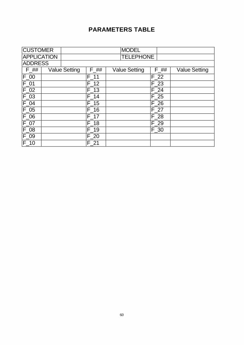
PARAMETERS TABLE
CUSTOMER MODEL APPLICATION TELEPHONE ADDRESS F_## Value Setting F_## Value Setting F_## Value Setting
F_00 F_11 F_22 F_01 F_12 F_23 F_02 F_13 F_24 F_03 F_14 F_25 F_04 F_15 F_26 F_05 F_16 F_27 F_06 F_17 F_28 F_07 F_18 F_29 F_08 F_19 F_30 F_09 F_20 F_10 F_21


![lightsaveled.comlightsaveled.com/pdf/LS_DirectFit%E2%84%A2_T5_LED_tube.pdfReflect2 10 1236.59 Imlm 0.8/0.8 0 Cel Wall Floo 0.7 0.5 0.2 0.5 0.3 0.2 4 6 5 78910 Iso- Lux[lx] 33m o. 67m](https://img.dokumen.tips/doc/110x75/5f8ceea5acfef00b384e1872/e284a2t5ledtubepdf-reflect2-10-123659-imlm-0808-0-cel-wall-floo-07-05.jpg)