Embed Size (px)
Citation preview

ROTOR INTERNAL FRICTION INSTABILITY
Donald E. Bently and Agnes Muszynska Bently Rotor Dynamics Research Corporation
Minden, Nevada 89423
Two aspects o f internal f r i c t i o n af fect ing s t a b i l i t y o f ro ta t i ng machines are dis- cussed i n t h i s paper. the leve l o f e f fect ive damping during ro to r subsynchronous and backward precessiinal vibrat ions caused by some other i n s t a b i l i t y mechanisms. The second r o l e o f in ternal f r i c t i o n consists o f creat ing ro to r i n s t a b i l i t y , i.e,, causing sel f -exci ted subsyn- chronous vibrations. Experimental t e s t resul ts document both o f these aspects.
The f i r s t r o l e o f internal f r i c t i o n consists o f decreasin
1. INTRODUCTION
I n ro tat ing machines, damping ef fects are conventionally s p l i t i n t o two categories: external and internal damping. The te rm "external" re fers t o the stat ionary e le - ments and ro to r environment, as they are "external" t o the r o t o r . External damping i s re lated t o energy dissipat ion due t o f r i c t i o n occurring between stat ionary and ro ta t i ng elements, and/or f l u i d dynamic resistance i n the ro to r environment (mostly i n f lu id- lubr icated bearings). External damping i s also supplied by material damp- ing of supports. External damping forces depend on the r o t o r absolute ve loc i ty o f vibrat ion, and t h e i r effect on the ro to r v ibrat ion i s usually welcome -- they pro- vide s t a b i l i z i n g factors.
The term " internal" refers t o the ro ta t i ng elements, including the r o t o r i t s e l f . The same physical phenomena characterize internal and external damping. damping forces are due t o material damping i n ro ta t i ng and v ibrat ing elements (most- l y shafts) and f r i c t i o n between rotat ing parts (such as j o i n t couplings and shrink- f i t t e d disks on shafts). As internal damping occurs i n the elements involved i n ro- t a t i n g motion, the internal damping forces depend on r e l a t i v e veloci ty, i .e., on the dif ference between the absolute v ibrat ion ve loc i ty and the ro ta t i ve speed. Thus the re la t i ve veloci ty may be "posit ive" (following absolute ve loc i ty when ro ta t i ve speed i s low) o r "negative" (opposing absolute ve loc i ty when ro ta t i ve speed i s high). The corresponding internal damping forces can, therefore, act as a s t a b i l i z i n g (adding t o the external damping t o increase the t o t a l e f fec t i ve damping i n the system) o r a destabi l iz ing factor (subtracting from the external damping t o decrease the t o t a l e f fect ive damping o f the system).
The te rm "damping" i s t r a d i t i o n a l l y related t o the s t a b i l i z i n g ef fects created by the i r revers ib le conversion o f k ine t i c energy t o heat. Being physical ly related t o the same mechanism, ro to r internal damping plays an addit ional r o l e i n ro ta t i ng ma- chines -- i t opposes the external damping and actual ly transfers the rotat ional energy i n t o vibrations. That i s why the term "damping" does not f i t w e l l i n t h i s situation; by contrast, the term " internal f r i c t i o n " does not introduce ambiguity concerni ng stabi 1 i z a t i on.
Internal f r i c t i o n has been recognized as a cause o f unstable r o t o r motion f o r more than 50 years [l-73. Since the f i r s t descript ion o f internal f r ic t ion-re la ted in-
Internal
337
https://ntrs.nasa.gov/search.jsp?R=19860020715 2020-04-28T19:48:09+00:00Z

stabi l i ty , many other ro tor destabilizing factors have been identified, such as rub o r fluid dynamic effects in fluid-flow machines and/or bearings and seals. t e r effects are much stronger than the internal friction effects and very often ob- served in the performance of rotating machines. 'They result i n subsynchronous vi- brations (rotative speed higher than vibrational frequency). Internal friction i s now very seldom identified as a main cause of rotor unstable motion. However, in- ternal friction plays a negative role by reducing the system-effective damping f o r forward subsynchronous and backward vibrations caused by other destabilizing factors.
I n th is paper two aspects of rotor internal f r ic t ion are discussed: damping-reducing effect and the second, a cause of instabi l i ty and self-excited v i - brations. The experimental t e s t results document both aspects.
The la t -
the f i r s t , a
2. ROTOR MODEL WITH INTERNAL FRICTION
To simplify the considerations, a symmetric .rotor w i l l be discussed. ior of a ro tor in i t s lateral mode of vibrations is usually represented by a set of linear ordinary differential equations. t o two, which for a symmetric ro to r can be presented in the form of one complex variable equation [ 8 ] :
Dynamic behav-
For each mode, the se t of equations reduces
F(& 'wz) - MZ + 0; + Kz + - 0,
where x, y are rotor horizontal and vertical deflections correspondingly, they de- scribe the rotor precessional motion. M is the rotor mass; D is the external vis- cous damping coefficient; K i s the rotor s t i f fness , including the shaft and pedestal stiffness. The rotor parameters M, D, K are generalized parameters corresponding t o each separate mode; w is rotative speed. The equation (I) may, i n particular, de- scribe ro to r a t i t s f i r s t mode. Eq.(l) contains frequency Q of the resulting pre- cessional motion, unknown a p r i o r i ; IQ-wl is the value of the shaft actual bending frequency. I t has been introduced t o the rotor model (1) following the way by which hysteretic damping i s usually included i n models of mechanical systems: a viscous damping coefficient i s replaced by a product Kq/R*, where K is s t i f fness coeffi- cient, q is loss factor, and R* represents the frequency of e las t ic element deforma- t i o n . In the case of rotating shaft, the frequency of deformation i s equal t o a difference between rotative speed and frequency of precession. Note that for for- ward low frequency precessions, the frequency of shaft deformation is lower than .
rotative frequency. a sum of rotative speed and frequency of precession. For circular synchronous pre- cession (h), the shaft i s "frozen" into a fixed bow shape, so that internal fric- t i o n does not act.
For backward precessions, the frequency of shaft deformation is
In Eq.(l) F (assumed positive) is internal f r ic t ion function. hysteretic damping F is constant and equal t o Kq. Generally, however, F can be a nonlinear function of z and z [4, 6, 91.
For shaft material For the 2ynchronous precession F=O.
338

For F = const and $2 supposed constant, subs t i t u t i ng z = Zrest, the eigenvalue problem o f (1) y ie lds four eigenvalues ( s a t i s f y i n g the degrees of freedom o f eq. ( l l ) ) * :
s = -6 2 ( l / f i ) [ j 6 2 - K / M + fi f jJK/M-62+fil where
6 = (0 + F/IQ-w1)/(2M), A = (g2 - K/M)* + F2w2/[M2(Q-w)*]
The rea l pa r t s o f (2) are non-positive, i.e., the system (1) i s s tab le when
which f o r UJ >-0 y i e l d s the fo l low ing conditions: F ~ W ~ M / K < ( D I Q - ~ ~ + F)Z
For w2 7 K/M i t i s s tab le only if IF1 5 DlQ-wi/[u/,/R7R-ll (4)
s = + j j l V F ~ (5)
(3)
For lu2 < K/M t he r o t o r pure ro ta t i ona l motion is stable.
A t a threshold o f s t a b i l i t y , i.e., when IF1 = D l Q - w / / [ u / ~ - 1 3 the eigenvalues reduce t o
The r o t o r motion i s pure ly per iod ic w i t h the natura l frequency determined by s t i f f - ness and mass ( f o r the s tab le motion below the threshold of s t a b i l i t y , the frequency i s s l i g h t l y lower than m, due t o damping).
I f the s t a b i l i t y cond i t ion i s no t s a t i s f i e d and F exceeds the l i m i t s (4), then r o t o r pure r o t a t i o n a l motion is unstable. f o r h igh l a t e r a l de f lec t ions nonlinear fac to rs become s ign i f i can t . eventual ly lead t o a l i m i t cyc le o f se l f -exc i ted v ibrat ions. The l a t t e r usua l ly oc- cur w i t h the lowest natura l frequency determined by the 1 inear model, as the non- 1 i near i ti es have very m i nor i nf 1 uence on frequency. the frequency Q can be, therefore, equal t o the r o t o r f i r s t na tura l frequency:
The l i n e a r model (1) is not adequate anymore, as Nonlinear fac to rs
With h igh amount o f probabi 1 i t y ,
Q = k + / K X (6)
*Solving the quadratic in s gives
Expanding q G = c + jd and solving f o r (c,d) gives r-
Substituting
gives four roots:
M and b
339

where the index "1" refers t o the f i r s t bending mode. f i r s t mode, the s t a b i l i t y condition (4) reduces t o
I f the model (1) describes the
I F / < D+/m z 2Kl(ll (7)
where C1 'is the damping factor o f the f i r s t mode. F o r the hysteret ic damping, F = Klql and the inequal i ty (7) y ie lds
r l l L 251 (8)
i.e., f o r s t a b i l i t y the shaft loss factor has t o be lower than the double o f external damping factor.
The modal aDDroach t o the ro to r modelization Dermits evaluation o f the s t a b i l i t y con- d i t ions for 'several modes. Fo r example, the inequal i ty (4) f o r the i - t h mode, (index 'W is:
IF1 2 Di t d m - w l / C w / d ~ - 11 (9)
Figure 1 i l l u s t r a t e s the condit ion i n which the same amount o f in ternal f r i c t i o n may cause the f i r s t mode t o be stable and the t h i r d mode unstable. This condi t ion takes place when the modal damping r a t i o i s s u f f i c i e n t l y high, D 1 / D 3 > ,/a/Jm and when the ro ta t i ve speed exceeds a speci f ic value, i . e, :
3. ROTOR EFFECTIVE DAMPING REDUCTION DUE TO INTERNAL FRICTION
Assume t h a t the r o t o r performs steady nonsynchronous precessional, sel f -exci ted v i - brat ion wi th frequency Q. ( f o r instance, it may be o i l whip). i n the form
jQt z = Ae
This v i brat ion occurs -due t o any instab i 1 i t y mechani sm It means tha t the ro to r motion can be presented
(11)
where A i s an amplitude of the self-excited vibrations. gives
Introducing (11) i n t o (1)
-MR2 + D j Q + K + F (Q-w)/lQ-wl = 0
The real pa r t o f t h i s expression y ie lds the frequency. The imaginary p a r t re lates t o the system damping. The external damping term, Mz, i s now completed by the t e r m expressing internal f r i c t i o n :
DR -* [xr + F (Q-w)/lQ-wI o r
D + F/Q f o r wtQ (supersynchronous precession) D - F/Q f o r w R (subsynchronous and backward precession) -*
For supersynchronous precession in ternal f r i c t i o n adds t o external damping and in- creases i t s level. Fo r subsynchronous and backward precession, the in ternal f r l c - t i o n reduces the leve l o f "posit ive" s t a b i l i z i n g damping i n the r o t o r system by the amount F/Q. r o t o r e f fect ive damping factor decreases by the fol lowing amount:
Taking i n t o account t h a t Q = m, f o r subsynchronous precession the
340

5 + 5 - F/(2K)
I t also means that the Amplificat
Q + Q/(l-FQ/K)
I f , fo r instance, the Synchronous
on Factor Q increases
Amplification Factor s 5 and internal friction i s due t o shaft material hysteretic damping w i t h loss factor r l = 0.06 (F=Kq), then the Subsynchronous Amplification Factor increases t o 7.14 (the Supersynchronous Ampli- fication Factor decreases t o 3.85).
Note that the decrease of the "positive" external damping f o r ro tor subsynchronous vibrations does n o t depend on the form of the function F (constant or displacement dependent).
In practical observations of rotating machine dynamic behavior, i t has very often been noticed that subsynchronous vibrations are characterized by much higher amp1 i - tudes than any super-synchronous vibrations. subharmonic vibrations i n rotating machines. internal friction opposing and decreasing the level of external, stabilizing damping i s very important. Although not a primary cause o f instabil i ty, internal f r ic t ion often promotes subsynchronous vibrations and causes an increase o f amplitudes. Figures 2, 3, and 4 i l lusixate dynamic responses of some unstable rotating machines. The self-excited, subsynchronous vibration amplitudes are much higher than amp1.i- tudes of synchronous and supersynchronous vibrations. More examples are given i n 183.
The rotor model considered i n this paper i s symmetric; therefore, the synchronous precession i s expected to be circular. s ion a t constant rotative speed, the bent shaft precesses "frozen" and is not a sub- ject of periodic deformation. The regular c i r - cular synchronous precession of real rotors very seldom occurs, however; usually nonsymmetry i n the ro to r and/or supporting system results in the el l ipt ical syn- chronous precession. w i t h the frequency two times higher than the rotat- iKpeed. then brings a "positive" effect:
There are many different causes of In each case, however, the role of
I n the case of circular synchponous preces;
The internal friction does not act.
I n this case, the bent shaft i s not "frozen," b u t deforms
i t adds t o the external damping, The internal f r ic t ion
4. SELF-EXCITED VIBRATIONS DUE TO INTERNAL FRICTION
If i n the equation (1), F is given i n the form of a nonlinear function o f the rotor radial displacement IzI, velocity of the radial displacement d l z l / d t and relative angular velocity u-0, [4,6] where
i.e., F = F(lz1, d l z l /d t , u-8) then t h e rotor model (1) allows for the following particular solution
where B and R are constant amplitude and frequency of the circular precessional self-excited vibrations correspondingly. algebraic relation yielded by (1) and (16):
e ( t ) = arctan [y(t)/x(t)], Izl = 4 w (15)
L( t) = BejRt (16)
They can be found from the following
-hQ2 + DjR + K + jF(B,O,w-a)(a-w)/lR-wl = 0
The nonlinear differential function F becomes nonlinear algebraic function.
341

Bolotin [9 ] quotes several forms of internal friction function F; for instance, for a shrink-fitted disk on the shaft, the internal friction nonlinear function the following form:
F (121, dlzl/dt, w-6) = cllzln
C* + (w- 6 )m where C1>O, C2>0, n, m are specific constant numbers. equation (17) for the first mode yields
In case of the function (18)
Q=m , 6 = (CC2 + (w-JR;~FT;)"I D m / C~ll'~ (19) Since C and C2 are positive, the solution (16) with amplitude (19) exists for w > , / m i only. ciently high rotative speed.
This means that the self-excited vibrations (16) exist for suffi-
5. INTERNAL FRICTION EXPERIMENT
During balancing of the three-disk rotor rig (Fig. 5), an appearance of self-excited vibrations at the rotative speed above third balance resonance have been noticed (Fig. 6). The frequency of these self-excited vibrations exactly equals first natu- ral frequency. The self-excited vibrations disappear for higher rotative speed. It was noted that when balancing weights, which affect the balance state for the third mode, were removed, causing a significant increase of the amplitude of the synchronous vibration at the third mode, the self-excited vibrations nearly disap- peared (the amplitude decreased from 1.8 to 0.4 mils p/p, compare Figs. 6 and 8). It appeared that the energy from self-excited vibrations was transferred to the syn- chronous vibrations. Higher rotor deflection due to unbalance evidently caused some substantial modifications in the self-excitation mechanism.
Since there was no other obvious reason for the self-excitation, internal friction (of the shaft material and disk/shaft joints) was blamed for the appearance of these self-excited vibrations. To prove this supposition, an increase of the rotor inter- nal friction was attempted. Half of the shaft was covered with a 4-mil-thick layer of damping material, commonly used for vibration control (acrylic adhesive ISD-112, 3M Company). Applied to the rotating shaft, the damping material increases the in- ternal friction and magnifies the self-excitation effect. The expected result was confirmed: the amplitude o f the self-excited vibrations increased from 0.4 to 0.7 mils p/p (compare Figs. 8 and 9).
The self-excited vi brations disappeared completely when the disks were eventual ly welded to the shaft, and the damping tape was removed.
The question of why the self-excited vibrations occur at the rotative speed -7150 rpm and disappear i n the higher range of speeds has not been answered. internal damping function identified. The analysis presented in Section 2 gives, however, some indications that a nonlinear internal damping function may cause rotor instability in a limited range o f rotative speeds. Figure 10 presents the stability chart for three modes.
Nor was the
6. CONCLUDING REMARKS
This paper discusses two important aspects of internal friction in rotating ma-
342

chines. Firstly, the internal friction in rotating elements causes a decrease of the amount of effective damping in the rotor system. This effective damping reduc- tion occurs during rotor subsynchronous and backward precessional motion, which may be caused by any instability/self-excitation mechanism (such as rub or fluid flow dynamic forces). While usually not a primary cause of instability, internal fric- tion promotes unstable motion and affects the value of self-excited vibration amp1 i tudes.
Secondly, the internal friction occasionally is a major cause of rotor self-excited vibrations due to incorrect shrink fits, loosening of shrink fits by differential thermal growth, or by mechanical fatigue. Known for more than 50 years as a con- tributor to rotor instability, the internal friction analytical model has not, however, yet been adequately identified.
This paper documents experimentally these two aspects of internal friction in rotat- ing machines and gives a qualitative description of the dynamic phenomena associated with rotor internal friction.
SYMBOLS
A,B -- Amplitudes of self-excited S -- Ei genval ue D -- External damping coefficient (x-horizontal , y-vertical)
KYM -- Rotor generalized (modal) 9 -- Angle of precessional motion Q -- Amp1 i fi cati on Factor R -- Angular speed of precession
vi brati ons z=x+jy -- Rotor radial deflection -- External damping factor -- Loss factor F -- Internal friction function 5
j=J-’I: rl
stiffness and mass coefficients w -- Rotative speed
REFERENCES
1. Newkirk, B. L.: Shaft Whipping. Gen. Elect. Rev. , 27, 1924. 2. Kimball , A. L.: Internal Friction Theory of Shaft Whirling. Gen. Elect. Rev. ,
27, 1924. 3. Kimball, A. L.: Internal Friction as a Cause of Shaft Whirling. Phil., Mag.,
49, 1925, 4. Tondl, A.: Some Problems of Rotor Dynamics. Prague, 1965. 5. Loewy, R. G., Piarulli , V. J.:
bration Information Center, SVM-4, 1969. 6. Muszynska, A.: On Rotor Dynamics (Survey). Nonlinear Vibration Problems, 13,
Warsaw 1972. 7. Bently, D.E.:
Friction: 8. Muszynska, A. : Rotor Instability. Senior Mechanical Engineering Seminar,
Bently Nevada Corporation, Carson City , Nevada, June 1984. 9. Bolotin, V. V.: The Dynamic Stability of Elastic Systems (translated from
Russian). Holden-Day Inc. , San Francisco, 1964. 10. Wachel , J. C.:
bility Problems in High-Performance Turbomachinery -- 1982, Proceedings of a Workshop Held at Texas AM University, College Station, Texas, NASA CP 2250, May 1982.
gal Compressors.
Dynamics of Rotating Shafts. The Shock and Vi-
The Re-excitation o f Balance Resonance Regions by Internal Kimball Revised, Bently Nevada Corp. BNC-19, 1982.
Rotordynamic Instability Field Problems. Rotordynamic Insta-
11. Bonciani, L., Ferrara, P. L. , Timori , A,: Aero-induced Vibrations in Centrifu- Rotordynamic Instability Problems in High-Performance Turboma-
343

chinery, Proceedings o f a Workshop held at Texas A&M University, College Sta- tion, Texas, NASA CP 2133, May 1980.
of Electromagnetic Field. Bently Nevada Corporation, 1983. 12. Muszynska, A.: Instability o f the Electric Machine Rotors Caused by Irregularity
Figure 1. - Regions of stabi 1 i ty for rotor f i r s t and third modes.
Figure 2. - Casiade spectrun o f steam turbine vibrational response, indicating high subsynchronous vibrations. Data courtesy of J.C. Wachel ClOl.
344

. . . . . . . , - 0 m w
Figure 3. - Time histories o f six-stage canpressor a t 9220 rpm. Subsynchronous vibrations due to destabilizing dynamic forces generated on last stage. Data courtesy o f P.L. Ferrara 1111.
O.LX 1.i
.. . . . . . , :: >' *.
:y *.-,: - * . . ,
FREQLEHICY <EVENTS/P4IN L l O U Q i .:' . . . . t . . . . , . . . , . . . . , . . . . I . . . . 8 . . . . I .
? ,-l
'9 - - 0:. 'J
Figure 4. - Cascade p lo t o f electr ic motor response during shutdown. A t
0 z
running speed o f 510 rpm (below f i r s t balance resonance), high half-speed vibrations present due t o electromagnetic f i e l d unbalance C121.
34 5

1. 2. 3. 4. 5. 6.
7. 8.
BASE PLATE MOTOR F L E X I B L E COUPLING R I G I D BEARING KEYPHASOR D I S K X-Y NONCONTACTING PROBES S T E E L D I S K S S T E E L SHAFT
Figure 5. - Threedisk rotor rigidly supported. Disks attached to rotor by radial screus. (Dimensions are in inches.)
1102 RPM F I L T
- a u m yo.u.nn
'E 'Dcn I x F I L T E R E D AT 7150 RPM
RUN: S
RPM
'Figure 6. - Startup response of three-disk rotor measured at midspan position. Cascade spectrum and orbits indicate existence of subsynchronous self-excited vibrations.
346

. . . . . . . . . . . . . . * . . . . . . . . . . . . . . . . . . . . . . . . . . . . .
SPEED, RPN x 1009
Figure 7. - Bod6 plots of 1X (synchronous) f i l tered rotor response and rotor mode shapes. Original state of unbalance
1102 RPM FILTERED
-- L I U . L . ~
RPM
Figure 8. - Cascade spectrum and orbits of unbalanced shaft: Decrease of subsynchronous self-excited vibrations. Oata fran midspan position.
347
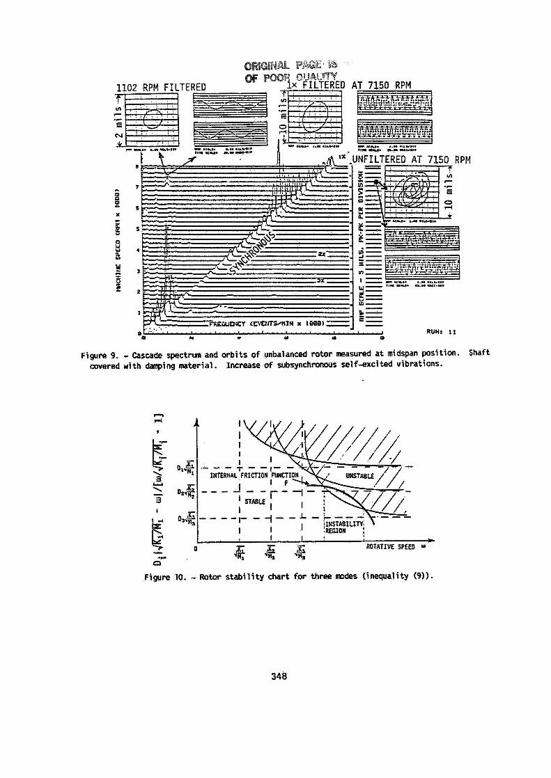
Figure 9. - Cascade spectrun and orbits of unbalanced rotor measured at midspan position. Shaft covered with danping material. Increase of subsynchronous selfsxcited vibrations.
n rl
I
\ 3 \
3
U - I
F i gure 10. - Rotor stability chart for three modes (inequality (9)).
348


![1 Rotor service On car brake lathe. 2 Rotor runout Rotor runout [wobble] causes pedal pulsation and vibration during braking. Beside irritating customers](https://img.dokumen.tips/doc/110x75/56649e535503460f94b48dc2/1-rotor-service-on-car-brake-lathe-2-rotor-runout-rotor-runout-wobble-causes.jpg)