Embed Size (px)
Citation preview
GEK-24986&
GB wrrol* DC SCR DRIVES
FLU WAVE, NON REGENERATIVE
INSTALLATION - OPERATION - MAINTENANCE
(Photo MG-5274-5)
These instructions do not purport to cover all details or variations in equipment nor to provide for every possible contingency to be met In connection wlh mslalhtion. operation or maintenance. Should further information be desired or should particular problems arIse whxh are not covered suffxiently for the purchaser’s purposes, the matter should be referred to General Electric Company.
E ELECTRIC TRADEMARK OF GENERAL ELECTRIC COMPANY. USA.
GEK-24986A
TABLE OF CONTENTS
PAGE Introduction ........................................................................ ...5
Receiving, Handling and Storage. .......................................................... .5 Safety for Personnel and Equipment. ....................................................... .6 Installation ....................................................................... ...6 Maintenance ...................................................................... ...8
.Fans and Filters ................................................................... .8 DCMotors ..................................................................... ...8 Printed Circuit Cards .................................................................. 9 Silicon Controlled Rectifiers ........................................................... .9 ControlDevices ................................................................... ..g
Instruction Information ................................................................ .9 TypesofDiagrams ................................................................. ..g
General Description. ................................. Basic Elements ................................... Power Supply Card ................................ Main Control Card. ................................
Test Instrument and Probe ......................... Interface Card. ................................... Motor Field Exciter Card ............................ Motor Field Control Card ............................ Diagnostic Card. .................................. Control Fuses, MOV’s .............................. Power Connections ................................ Control Connections ...............................
Specifications for Basic Drives . Modifications . . . . . . . . . .
........ ......................... 11
........ .........................
........ ......................... ::
.................................. 12
. . . . . . . . . . . . . . . . . . . . . . . . . . . . . . . . . . 12
........ ......................... 13
........ ......................... I3
........ ......................... 13
........ ......................... 14
........ .........................
........ ......................... :t
.................................. 15
......................... 16
......................... 19
Interconnection . . _ . . . . . . . . . . . . . . . . . . . . . . . . . . . . . . . . . . . . . . . . . . . . . . . . . . . . . . . . . . . . . . . . . . .20 General . . . . . . . . . . . . . .................................. AC Power Connection . . . .................................. Final Check . . . . . . . . . . ..................................
......................... 20
.........................
......................... 2”;
Startup . . . . . . . . . . . . . . . . . . . . . . . . . . . . . . . . . . . . . . . . . . . . . . . . . . . . . . . . . . . . . . . . . . . . . . . . . ...29
Sequence of Operation. . . . . Power Annlied . . . . . . . .
. . . . . . . . . . . . . . . . . . . . . . . . . . . . . . . . . . . . . . . . . . . . . . . . . . . . . . . . . . . . 29
. . . . . . . . . . . . . . . . . . . . . . . . . . . . . . . . . . . . . . . . . . . . . . . . . . . . . . . . . . . . 29 Start. . : 1 ........... . . . . . . . . . . . . . . . . ................. ..............
Switch Logic ....... ....... ....... ......... ................. .............. ;z I Signal Flow ........ ....... ....... ......... ................. .............. 34
stop ............... ....... ....... ......... ................. .............. Diagnostic Static. ...... ....... ....... ......... ................. .............. ;:
Logic ............ ....... ....... ......... ................. .............. 35 Signal Flow ........ ....... ....... ......... ................. .............. 35
Diagnostic Run. ....... ....... ....... ......... ................. .............. 36
Calibration Procedure. .................................................................. .36 Calibration with Motor Field Control ...................................................... .36
Calibration with Motor Field Exciter. .................................................... .40
Modifications and Options ................................. Dynamic Braking. ..................................... Reversing ...........................................
Armature Reversing. ................................. Field Reversing. ....................................
AC Line Circuit Breaker ................................. Blower Motor Control .................................. Diagnostic panel ...................................... Test Instrument ...................................... Process Control Follower ................................ Jog by Pushbutton/Independent Jog Reference. .................
.............................. .............................. It .............................. 43
.............................. 43
.............................. 44
.............................. 44
.............................. 45
..............................
.............................. 2
.............................. 46
.............................. 47
GEK-24986A
TABLE OF CONTENTS (Continued)
PAGE Timed Overcurrent Card (TOC) .......................................................... .47 AutolManualControl..................................................................4 7 Remote Current Limit ................................................................ .48 SpeedIndicator......................................................................4 8 LoadIndicator......................................................................4 8 Tachometer........................................................................4 9
Troubleshooting ...................................................................... .49 Recommended Instrumentation. ......................................................... .49 Procedures.........................................................................4 9 HowtoTestandSCR ................................................................. .49
Removal/Repair.......................................................................5 0 ConversionModule...................................................................5 0 SCRReplacement....................................................................S 2 Fans.............................................................................5 2 MOV’S............................................................................~ 2 Printed Circuit Cards ................................................................. .52
Appendix...........................................................................................S 4 Outline Diagrams ........................................... . ...................................... 54 Elementary Diagrams ........................................................................... 57-70 Spare and Renewal Parts ........................................................................ 73-77 Power Wiring and Terminals ..................................................................... 78-82 Hot Lme Telephone Number ........................................................................ 83
Glossary of Terms ................................................................................ 84-86
LIST OF ILLUSTRATIONS
FIGURE PAGE
:: 3. 4.
2. 7:
98:
K: 12. 13. 14. 15.
it IX: 19.
2
2
i:- 26: 27.
Valutrol-GP Power Unit .............................................................. .7 Valutrol Block Diagram ............................................................. .I0 Valutrol Power Unit (Doors Open) ....................................................... 11 Power Supply Card ................................................................ .I1 MainControlCard..................................................................l 2 Interface Card. ................................................................... .13 Motor Field Exciter Card ............................................................ .14 Motor Field Control Card ............................................................ .I4 Diagnostic Card. .................................................................. .15 Control Fuse and MOV’s ............................................................ .15 Signal Connections ................................................................. .16 Interconnections of Power Unit and Motor. ................................................ .21 Interconnections of Operator Stations. ................................................. .24-28 Current Feedback (CFB) at low Current Level .............................................. .31 Current Feedback (CFB) at Continuous Current Level .............. ; .......................... .3 1 Voltage Feedback (VFB) at Low Current and 100 Volts. ....................................... .3 1 Voltage Feedback (VFB) at Continuous Current and 100 Volts ................................... .31 Oscillator(OSC)...................................................................3 2 InitialPulse(IPU)..................................................................3 2 Synchronizing Signal (SA). ........................................................... .32 Speed Feedback Signal (SFB) with AC Tach-450 RPM ......................................... .32 Tachometer Feedback Signal (TFB) with AC Tach-450 RPM. .................................... .33 Tachometer Feedback Signal (TFB) with AC Tach3 160 RPM .................................... .33 Speed Feedback Signal (SFB) with AC Tach3 160 RPM ........................................ .33 Pulse Output (PO) Normal ........................................................... .33 Pulse Output (PO) with One SCR Gate Lead Open. ........................................... .34 Gate to Cathode Firing Signal ......................................................... .34 -. .- -.
28. Diagnostic ‘I’est Circuits ............................................................. .36 28A. Typical Test Data Sheet ............................................................. .38 29. Dynamic Braking Resistor Connections ................................................... .41 30. Armature Reversing. ............................................................... .42 3 1. Field Reversing Panel. ............................................................. .43 32. Control Circuits with Dynamic Braking and/or Reversing ....................................... .45
3
G EK-24986A
LIST OF ILLUSTRATIONS (Continued)
FIGURE PAGE
:i: 3s. 36.
2. 39: 40.
t:: 43. 44. 4s. 46.
ti- 49: 50.
Diagnostic Panel .................................................................. .46 Process Control Follower ............................................................ .46 JogKlt.........................................................................4 7 Auto/Manual Control. .............................................................. .47 Remote Current Limit .............................................................. .48 Speed Indication. ................................................................. .48 LoadIndication.. ............................................................... ..4 9 Removal of Gate Leads. ............................................................. .50 Removal of Slotted Spacer ........................................................... .50 Removal of Conversion Module ........................................................ .51 Stud Mount Heat Sink (Front View). .................................................... .51 Stud Mount Heat Sink (Top View). ..................................................... -51 Press Pak Heat Sink (Front View). ...................................................... .51 Press Pak Heat Sink (Top View). ....................................................... .52 RemovalofFans...................................................................5 2 MOV’S(~OO-~~~HP)................................................................~ 2 Power Unit Outline Dimensions. ....................................................... .54 Isolation Transformer Dimensions ............. , ........................................ .55
36BS90240AA 36C764153AA Sh. 1 36C764146AA 36D868809BA 36C764157AB 36C764165AA 36C764169AA 36BS90232AA
36BS90140AA Sh. 2 36D86SS49AA 36C764162AA
TABLE
ELEMENTARY DIAGRAMS Basic Standard Drive ................................................. .57-60 Power Supply Card .................................................... .61 Interface Card. ..................................................... .63-64 Mam Control Card. .................................................. .65-66 Diagnostic Card. ...................................................... .67 Field Reversing/Anti Plugging Card. ......................................... .68 Anti Plugging Card. .................................................... .69 Process Follower/Jog Ref Card. ............................................ .70
CARD DIAGRAMS Power Supply Card .................................................... .62 Interface Card. ....................................................... .71 Main Control Card. .................................................... .72
LIST OF TABLES PAGE
I. Relationships Between Air Temperature, Relative Humidity and Dew Point ............................ .S II. Recalibrating Adjustment Sequences. .................................................... .37
III. Signal Connections .............................................................. .17-18 IV. Interconnection Chart ............................................................... .22
. Fault Conditions. ................................................................. .gO
4

GEK-24986A
INTRODUCTION
This Instruction Book contains helpful suggestions for placing the Valutrol drive equipment in service. It contains general information about drive operation and maintenance.
The operator and maintenance man should have ac- cess to a copy of this instruction book.
Additional instructions are included in the supple- mentary instruction publications and diagrams included in the instruction folder with the equipment.
RECEIVING. HANDLING AND STORAGE
RECEIVING
The equipment should be placed under adequate cover immediately upon receipt as packing cases are not suitable for out-door or unprotected storage. Each shipment should be carefully examined upon arrival and checked with the packing list. Any shortage or damage should be reported promptly to the carrier. If required, assistance may be requested from the General Electric Company, Speed Variator Products Operation, Erie, Pa. When seeking assistance please use drive serial number to identify the equipment. Telephone 814-455-3219.
HANDLING
Wall mounted power units can be transported by lift trucks with the forks completely under the base, care being taken that the unit does not tip.
STORAGE
If the equipment is not to be installed immediately, it should be stored m a clean, dry location at ambient tem- peratures from -2O’C (-4’F) to +55’C (131’F). The
surrounding air must be free of chemical and electrically conductive or corrosive contaminants.
Precautions should be taken to prevent condensation from forming within the equipment enclosure. If the stor- age environment exceeds a 15’C (27’F) drop m tempera- ture at 50% humidity over a 4 hour period, a space heater should be installed inside each enclosure to prevent con- densation. (A 100 watt lamp can sometimes serve as a sub- stitute source of heat). Higher humidities with smaller temperature changes will also cause condensation.
Condensation occurs when air containing some moisture is cooled below its dew point. The dew point represents saturation of the an, and is the temperature at which the moisture starts to condense into water. It is not a fixed temperature but rather is related to the initial temperature of the air and rts relative humidity at that temperature. The amount of moisture that can be held in the air is related to the air temperature. The following examples illustrate some of these relationships.
In Industrial drives, condensation is a possibility in applications where air temperature changes are large and rapid and/or the air is moist. For example, an outdoor crane operating in sunshine on a winter day, which then is shut down and parked in the shade will experience a rapid drop in temperature. This can result in condensation inside the equipment. Adding heat to keep the air temperature above its dew point can prevent condensation.
If storage temperatures below -2O’C (-4’F) are likely to be present then auxiliary heat should be added in each enclosure to maintain temperature at or above -2O’C. For assistance in heater size selection, contact the General Electric Company.
When a drive that has been in operation is shut down for either a short or extended period of time, it is recommend- ed the environmental conditions be maintained the same as when in operation. Power unit ventilation or heating and air
TABLE I
Relationships Between Air Temperature, Relative Humidity and Dew Point
AIR TEMP. OF. OC
RELATIVE WGT. OF MOISTURE DEW HUMIDITY IN 1 LB. OF DRY POINT
% AIR. GRAINS OF OC
104 40 100 34.5 104 40 104 40 80 270 97 36 104 40 40 130 75 24 104 40 10 32 37 3 50 10 100 54 50 10 50 10 80 42 43 6 50 10 40 21 25 4
GEK-24986A
conditioning (if used) should be left on during the down- time to prevent large changes in temperature and possible moisture condensation.
SAFETY FOR PERSONNEL AND EQUIPMENT
The following paragraphs list some general safety reminders and safety recommendations to be followed when operating or installing this equipment.
WARNING
DENOTES OPERATING PROCEDURES AND PRACTICES THAT MAY RESULT IN PERSONAL INJURY OR LOSS OF LIFE IF NOT CORRECTLY FOLLOWED.
COLOR - BLACK OR WHITE LETTERING ON RED FIELD.
CAUTION
DENOTES OPERATING PROCEDURES AND PRACTICES THAT, IF NOT STRICTLY OBSERV- ED, MAY RESULT IN DAMAGE TO, OR DE- STRUCTION OF, THE EQUIPMENT.
COLOR - BLACK LETTERING ON AMBER FIELD.
NOTE
DENOTES AN OPERATING PROCEDURE OR CONDITION WHICH SHOULD BE HIGHLIGHTED.
COLOR - BLACK LETTERING ON WHITE FIELD.
WARNING
IMPROPER LIFTING PRACTICES CAN CAUSE SERIOUS OR FATAL INJURY.
LIFT ONLY WITH ADEQUATE EQUIPMENT AND TRAINED PERSONNEL.
WARNING: HIGH VOLTAGE
ELECTRIC SHOCK CAN CAUSE PERSONAL INJURY OR LOSS OF LIFE. WHETHER THE AC VOLTAGE SUPPLY IS GROUNDED OR NOT, HIGH VOLTAGE TO GROUND WILL BE PRESENT AT MANY POINTS. WHEN INSTRUMENTS SUCH AS OSCILLOSCOPES ARE USED TO WORK ON LIVE EQUIPMENT, GREAT CAUTION MUST BE USED. WHEN ONE OF THE INSTRUMENT LEADS IS CONNECTED TO THE CASE OR OTHER ME- TAL PARTS OF THE INSTRUMENT, THIS LEAD SHOULD NOT BE CONNECTED TO AN UN-
GROUNDED PART OF THE SYSTEM UNLESS THE INSTRUMENT IS ISOLATED FROM GROUND AND ITS METAL PARTS TREATED AS LIVE EQUIPMENT. USE OF AN INSTRUMENT HAVING BOTH LEADS ISOLATED FROM THE CASE PERMIT GROUNDING OF THE CASE, EVEN WHEN MEASUREMENTS MUST BE MADE BETWEEN TWO LIVE PARTS.
WARNING
DO NOT SERVICE THE EQUIPMENT WHILE POWER IS APPLIED.
NOTE
ALWAYS READ THE COMPLETE INSTRUCTIONS PRIOR TO APPLYING POWER OR TROUBLE- SHOOTING THE EQUIPMENT. FOLLOW THE START UP PROCEDURE STEP BY STEP.
READ AND HELD ALL WARNING, CAUTION AND NOTE LABELS POSTED ON THE EQUIP- MENT.
CAUTION
DO NOT REMOVE INPUT POWER FROM THE DRIVE UNTIL IT HAS FULLY EXECUTED A STOP SEQUENCE, AS THIS CAN DAMAGE THE DRIVE SYSTEM.
INSTALLATION
LOCATION
DC-SCR drive power units are suitable for most factory areas where other industrial equipment is installed. They should be instaIled in well ventilated areas with ambient temperatures ranging from O°C (32’F) to 40°C (104’F) and relative humidities up to 90 percent. It should be recognized; however, that since the life expectancy of any electronic component decreases with increased ambient temperature, reduction of the ambient temperature will bring about extended component life. For example, longer component life should be expected if the ambient tem- perature is held between 20°C (68’F) and 30°C (87’F).
Proper performance and normal operational life can be expected by maintainmg a proper environment for the drive system.
6
GEK-24986A
(Photo MG-5244-6)
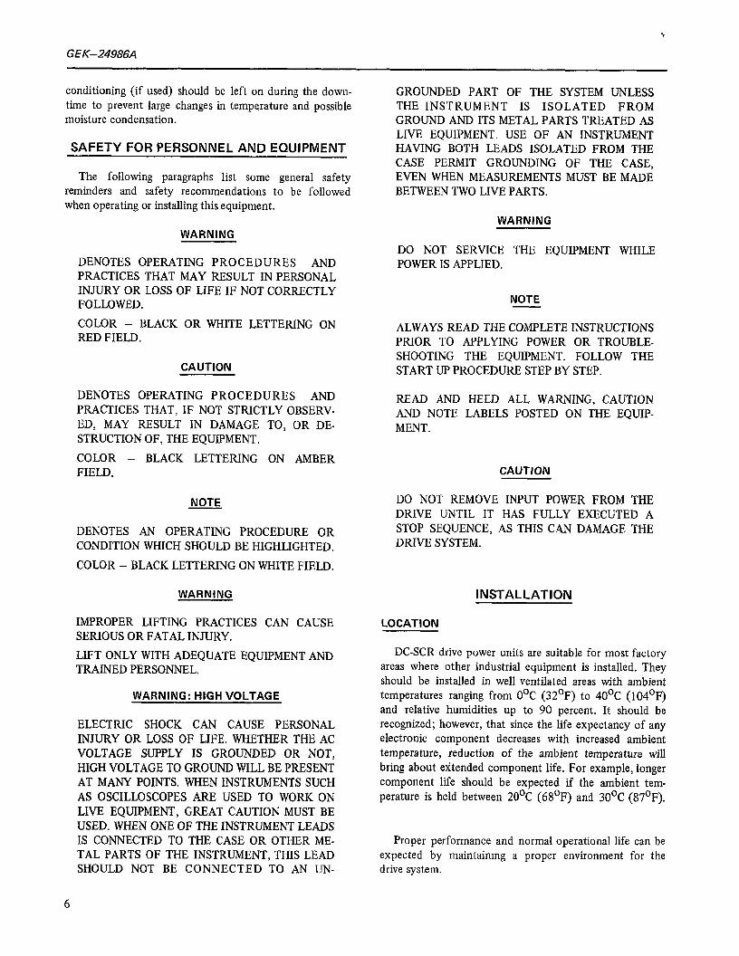
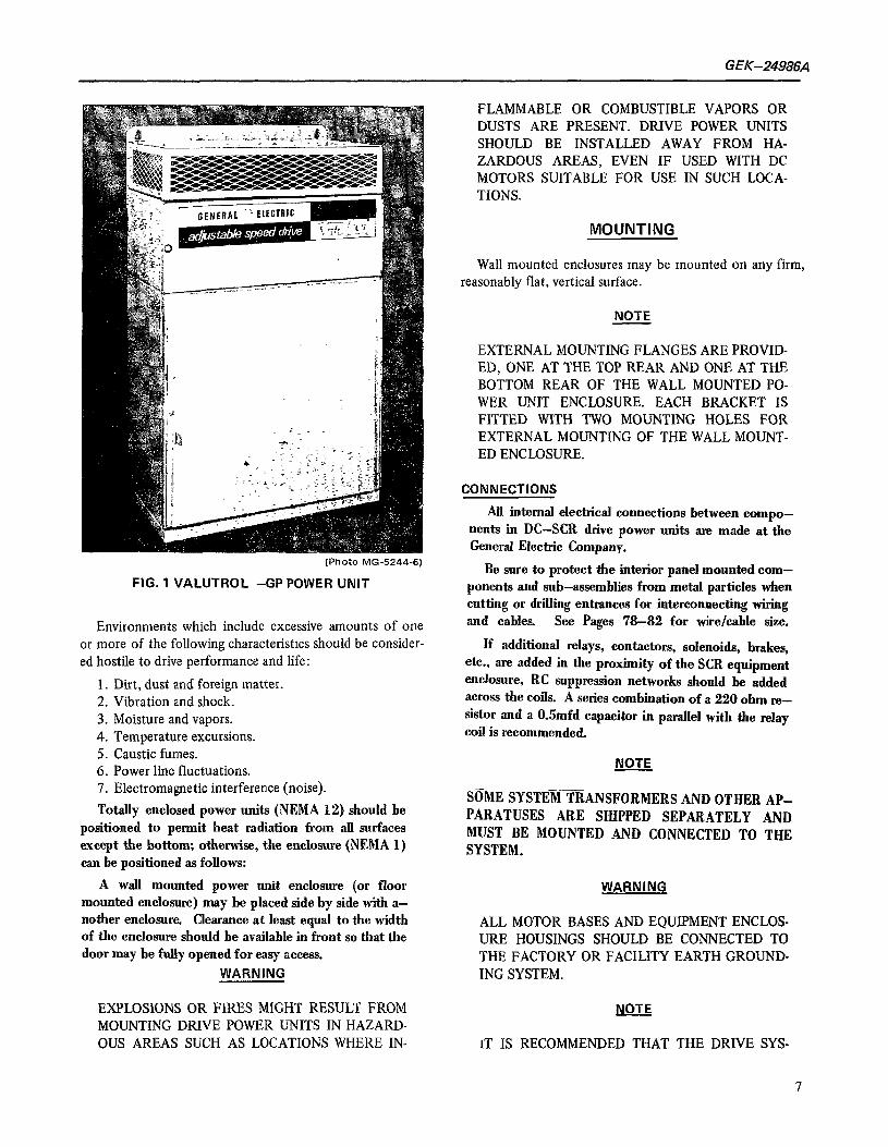
FIG. 1 VALUTROL -GP POWER UNIT
Environments which include excessive amounts of one or more of the following characteristics should be consider- ed hostile to drive performance and life:
1. Dirt, dust and foreign matter. 2. Vibration and shock. 3. Moisture and vapors. 4. Temperature excursions. 5. Caustic fumes. 6. Power line fluctuations. 7. Electromagnetic interference (noise).
Totally enclosed power units (NEMA 12) should be positioned to permit heat radiation from all surfaces except the bottom; otherwise, the enclosure (NEMA 1) can be positioned as follows:
A wall mounted power unit enclosure (or floor mounted enclosure) may be placed side by side with a- nother enclosure. Clearance at least equal to the width of the enclosure should be available in front so that the door may be fully opened for easy access.
WARNING
EXPLOSlONS OR FIRES MIGHT RESULT FROM MOUNTING DRIVE POWER UNITS IN HAZARD- OUS AREAS SUCH AS LOCATIONS WHERE IN-
FLAMMABLE OR COMBUSTIBLE VAPORS OR DUSTS ARE PRESENT. DRIVE POWER UNITS SHOULD BE INSTALLED AWAY FROM HA- ZARDOUS AREAS, EVEN IF USED WITH DC MOTORS SUITABLE FOR USE IN SUCH LOCA- TIONS.
MOUNTING
Wall mounted enclosures may be mounted on any firm, reasonably flat, vertical surface.
NOTE
EXTERNAL MOUNTING FLANGES ARE PROVID- ED, ONE AT THE TOP REAR AND ONE AT THE BOTTOM REAR OF THE WALL MOUNTED PO- WER UNIT ENCLOSURE. EACH BRACKET IS FITTED WITH TWO MOUNTING HOLES FOR EXTERNAL MOUNTING OF THE WALL MOUNT- ED ENCLOSURE.
CONNECTIONS
All internal electrical connections between compo- nents in DC-SCR drive power units are made at the General Electric Company.
Be sure to protect the interior panel mounted com- ponents and sub-assemblies from metal particles when cutting or drilling entrances for interconnecting wiring and cables. See Pages ‘78-82 for wire/cable size.
lf additional relays, contactors, solenoids, brakes, etc., are added in the proximity of the SCR equipment enclosure, RC suppression networks should be added across the coils. A series combination of a 220 ohm re- &or and a 0.5mfd capacitor in parallel with the relay coil is recommended.
NOTE
SoME SYSTEM TRANSFORMERS AND OTHER AP- PARATUSES ARE SHIPPED SEPARATELY AND MUST BE MOUNTED AND CONNECTED TO THE SYSTEM.
WARNING
ALL MOTOR BASES AND EQUIPMENT ENCLOS- URE HOUSINGS SHOULD BE CONNECTED TO THE FACTORY OR FACILITY EARTH GROUND- ING SYSTEM.
NOTE
IT IS RECOMMENDED THAT THE DRIVE SYS-
7
GEK-24986A
TEM COMMON CIRCUIT BE GROUNDED AT ONLY ONE POINT. IF THE DRIVE REFERENCE IS SUPPLIED BY A PROCESS INSTRUMENT WITH GROUNDED COMMON, THE DRIVE COMMON SHOULD NOT BE GROUNDED.
IF THE SECONDARY OF THE TRANSFORMER MUST BE GROUNDED, IT IS RECOMMENDED THAT HIGH RESISTANCE GROUNDING BE USED FOR GROUNDING THE TRANSFORMER NEU- TRAL.
CAUTION
INSTALLATION WIRING MUST BE IN ACCOR- DANCE WITH THE NATIONAL ELECTRICAL CODE, AND BE CONSISTENT WITH ALL LOCAL CODES. SECONDARIES OF 115 VOLT CONTROL TRANSFORMERS TYPICALLY HAVE ONE SIDE FUSED AND THE OTHER GROUNDED OR AVAILABLE FOR GROUNDING BY THE USER.
CAUTION
MEGGERING CAN DAMAGE ELECTRONIC COM- PONENTS. DO NOT MEGGER OR HI-POT WITH- OUT CONSULTING THE SPEED VARIATOR OPERATION, GENERAL ELECTRIC CO.
NOTE
CONNECTION OF EXTERNAL CIRCUITS OTHER THAN SHOWN ON THE ELEMENTARY DIAGRAM, SUCH AS AMMETERS ON THE SHUNT OR VOLT- METERS ON THE TACHOMETER MAY DEGRADE THE PERFORMANCE OF THE DRIVE SYSTEM.
CAUTION
DO NOT USE POWER FACTOR CORRECTION CAPACITORS WITH THIS EQUIPMENT WITH- OUT CONSULTING THE SPEED VARIATOR OPERATION, GENERAL ELECTRIC CO. DAM- AGE MAY RESULT FROM HIGH VOLTAGES GENERATED WHEN CAPACITORS ARE SWITCH- ED.
Before power is applied to the drive system, checks should be made to see that all internal connections are tight, and that all open relays and contactors operate freely by hand. Check that the equipment is clean and that no metal chips are present.
8
MAINTENANCE
Periodically inspect and maintain the equipment protec- tive devices (particularly air filters when supplied) per instructions in this section. Check all electrical connections for tightness; look for signs of poor connections and over heating (arcing or discoloration).
FANS AND FILTERS
On force ventilated drives, the power unit contains a fan and perhaps an air filter in the intake of the enclosure and/or on equipment inside the enclosure.
Inspect the fan at regular intervals to see that it is oper- ating properly. Check for excessive noise and vibration, loose fan blades and for over heating of the motors. Keep the fan blades clean.
If the fan does not operate, replace the fan and integral motor with a unit wrth the same catalog number.
Clean and/or replace air filter as appropriate depending on the accumulation of dirt for the type supplied.
To clean metal filters, flush only with warm water, dry and recoat lightly with RP super filter coat or equivalent (light oil) or replace the filter.
Be sure to install filters with air flow direction as indi- cated on the filter.
DC MOTORS
Maintenance instructions coveringbruahes,commu- tator and lubrication are in GEH-2304 or GEH-3967 which is found elsewhere in the instruction book
CAUTION
IT SHOULD BE NOTED THAT WHEN THEDRIVE SYSTEM ISSHUT DOWN AND POWERISNOTRE- MOVED FROM THE POWER UNIT THE MOTOR FIELD WILL CONTINUE TO BE EXCITED EVEN ATSTANDSTILL.
ALTHOUGH DC MOTORS ARE DESIGNED FOR FULL FIELD EXCITATIONATSTAND STILLFOR PERIODS OF TIME (SEVERAL HOURS), UNDER THIS CONDITION,POWER SHOULDBEREMOVED, OTHERWISE THE FIELD COILS WILL BE SUB- JECTED TOEXCESSIVETEMPERATUREANDSIG- NIFICANTLYREDUCEDINSULATIONLIFE.
AN ALTERNATE TO THIS PROCEDURE IS TO EMPLOY A FIELD ECONOMY CIRCUIT WHICH AUTOMATICALLY REDUCES THE LEVEL OF

GEK-24986A
EXCITATION WHENEVER THE DRIVE IS SHUT DOWN. SEE MOTOR FIELD CONTROL CARD (MFC).
PRINTED CIRCUIT CARDS
Prmted circuit cards normally do not require mainten- ance except to keep them clean and tightly secured to their respective terminal boards. Clean a’s follows:
1. Dry Dust - Vacuum clean, then blow with dry filter- ed compressed air (low pressure supply).
2. Oily Dirt - Certain components (electrolytic capa- citors, switches, meters, potentiometers and trans- formers) can be damaged by solvent, so its use is not recommended. If absolutely necessary, use solvent sparingly on a small brush and avoid above compon- ents. Clean contact terminals with dry non-liming cloth after solvent has been used. Recommended solvents- Freon RE or TF.
3. If the card is badly contaminated or corroded, replace.
SILICON CONTROLLED RECTIFIERS
Keep SCR’s and heatsink free from dirt, oil or grease, since any accumulation of dirt may cause overheating. Clean as follows:
1. Dry Dust - Vacuum clean, then blow with dry, filtered compressed air (low pressure).
CAUTION
SOLVENT CAN HARM NON-METAL COMPON- ENTS.
2. Oily Dirt - Use dry or barely moist (with solvent) non-liming cloth. Repeat until cloth remains clean. AlI SCR’s must be cleaned with dry non-liming cloth after solvent has been used. Recommended solvents: Freon RE or TF.
CONTROL DEVICES
Inspect all relays and contactors at regular intervals and keep them free from dirt, oil or grease. Check for freedom of moving parts, corrosion, loose connections, worn or broken parts, charred insulation or odor, proper contact pressure and remaining wear allowance on contacts. Do not lubricate the contacts as lubrication shortens theu life.
Both copper and silver contacts will become darkened and somewhat roughened in normal operation. This does not interfere with their performance, and does not indicate *Trademark of E. I. DuPont Co.
that the contacts should be filed. In general, contacts will not need attention during their normal life, but if promin- ent beads form on the surfaces due to severe arcing, the contact faces may be dressed with a fine file. Do not use sand paper or emery cloth.
Any contact that is worn to the point where contact wipe or pressure is lost should be replaced.
Cleaning procedure is the same as previously given for SCR and heatsink.
TYPES OF DIAGRAMS
Different types of control diagrams are provided for specific purposes. The type of control diagram is noted in the title block of each diagram sheet.
The three major types of diagrams are Elementary, (sometimes referred to as schematic), Layout or Con- nection and Interconnection.
The Elementary diagrams represent (in symbolic form) the fundamental operation and relationship of the electrical parts of a system. These diagrams are drawn in such a manner that the operation of the control system is easily understood. Mechanical relationships of control devices are subordinated to simple presentation of the electrical circuits. Con- nections made between control devices and power devices within the enclosure are also shown on this type of diagram.
The Layout or Connection diagram, when supplied, is one which shows the relative physical position of the devices as well as other electrical components located within the same enclosure.
The Elementary diagram also identifies adjustments, signals and test points. Adjustments are CAPITALIZ- ED and UNDERLINED in this instruction book. Example: FMAX (maximum motor field adjustment). Signals and test points are CAPITALIZED only, example: CFB (Current Feed Back).
In many cases the Elementary diagram will be com- bined with the Interconnection diagram, which will show the type and number of connections to be made between major components of the system such as the power unit, motor, operator’s station, the plant po- wer source, auxiliary devices and other electrical machines.
THE FOLLOWING INFORMATION IS OF PARTICULAR IMPORTANCE.
9

G EK-24986A
I I I I I
4
10
GEK-24986.4
INSTRUCTION INFORMATION
The instruction folder furnished with the equipment Includes detailed instructions and diagrams applicable to the basic drove system and the various options and modi- fications.
In addition to this general mformation the folder in- cludes instructions for the motor(s) and other components furnished. Start-up and troubleshooting guides are included. All instructions and the accompanying diagrams should be consulted before applying power to the system.
GENERAL DESCRIPTION
The basic elements of the Valutrol , full wave, non- regenerative DC SCR drive are shown in the simplified block diagram, Fig. 2, Valutrol Block Diagram.
Three phase AC power enters through the fuses and is fed through the line reactor, line contactor (MA) and enters the power conversion module (SCR) where it is converted to DC adjustable voltage. DC power is fed through a shunt to the DC motor armature.
The speed of the motor is proportional to the DC volt- age applied to its armature. Speed is measured by motor CEMF (Armature voltage feedback with IR compensation). As an optional feature, speed can be measured by a tach- ometer generator directly connected to the DC motor.
The remainder of the control is manufactured on four (4) removable printed circuit boards. These are the power supply card (PSC) the main control card (MCC) the inter- face card (IFC) and the motor field exciter card (MFE) or the motor field control card (MFC) (optional). Additronal cards are available for optional modifications, such as:
Diagnostic card Field reversing card Anti plug card Process Control Follower/Jog Reference card Timed Overcurrent card
Signal level power for the control is taken from the three phase input through control fuses to the control power transformer. This transformer is fitted with a 460/23OV reconnectable primary winding and two isolated secondary windings: (1) 115V to operate the coil of the MA contac- tor, the RUN relay and the conversion module cooling fans (rf required); (2) the second winding is a 50 volt center tapped secondary which provides the AC input to the po- wer supply card.
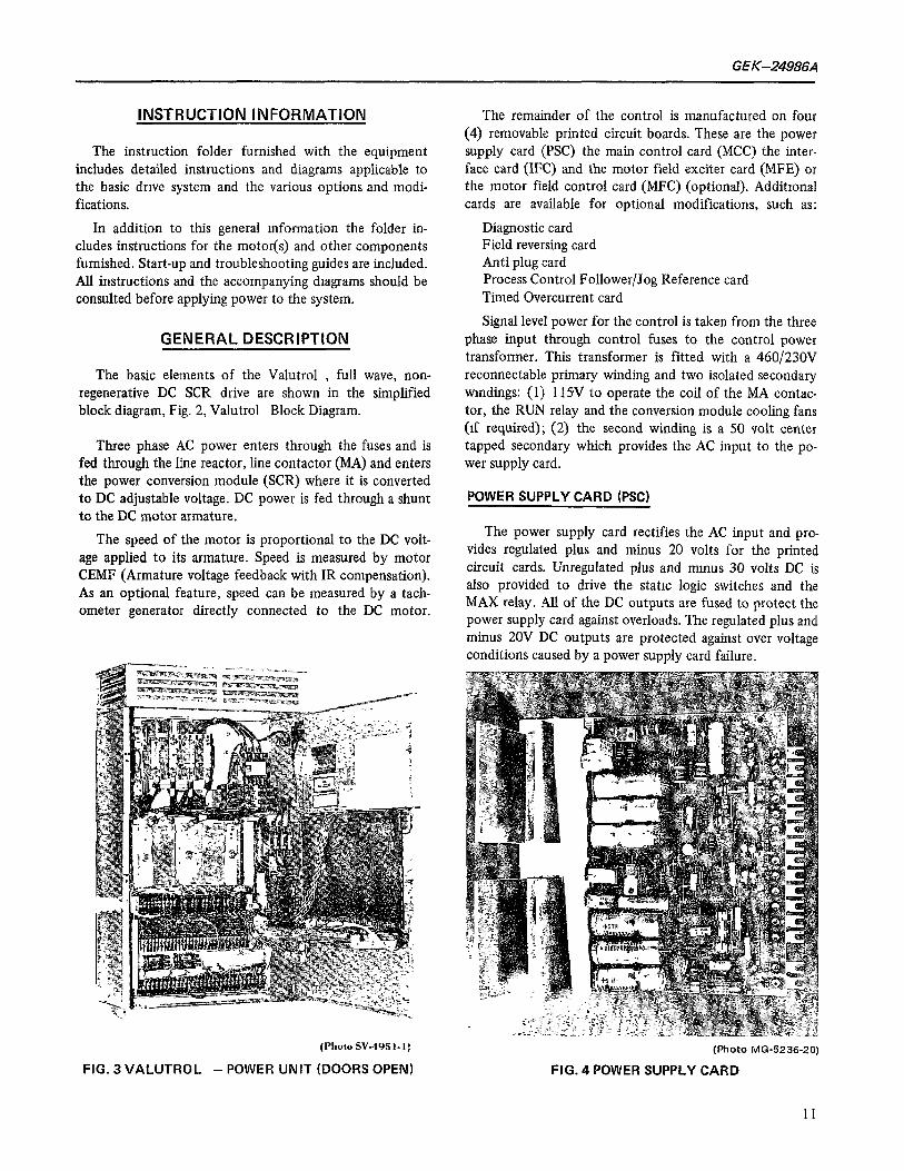
POWER SUPPLY CARD (PSC)
The power supply card rectifies the AC input and pro- vides regulated plus and minus 20 volts for the printed circuit cards. Unregulated plus and mmus 30 volts DC is also provided to drive the static logic switches and the MAX relay. All of the DC outputs are fused to protect the power supply card against overloads. The regulated plus and minus 20V DC outputs are protected against over voltage conditions caused by a power supply card failure.
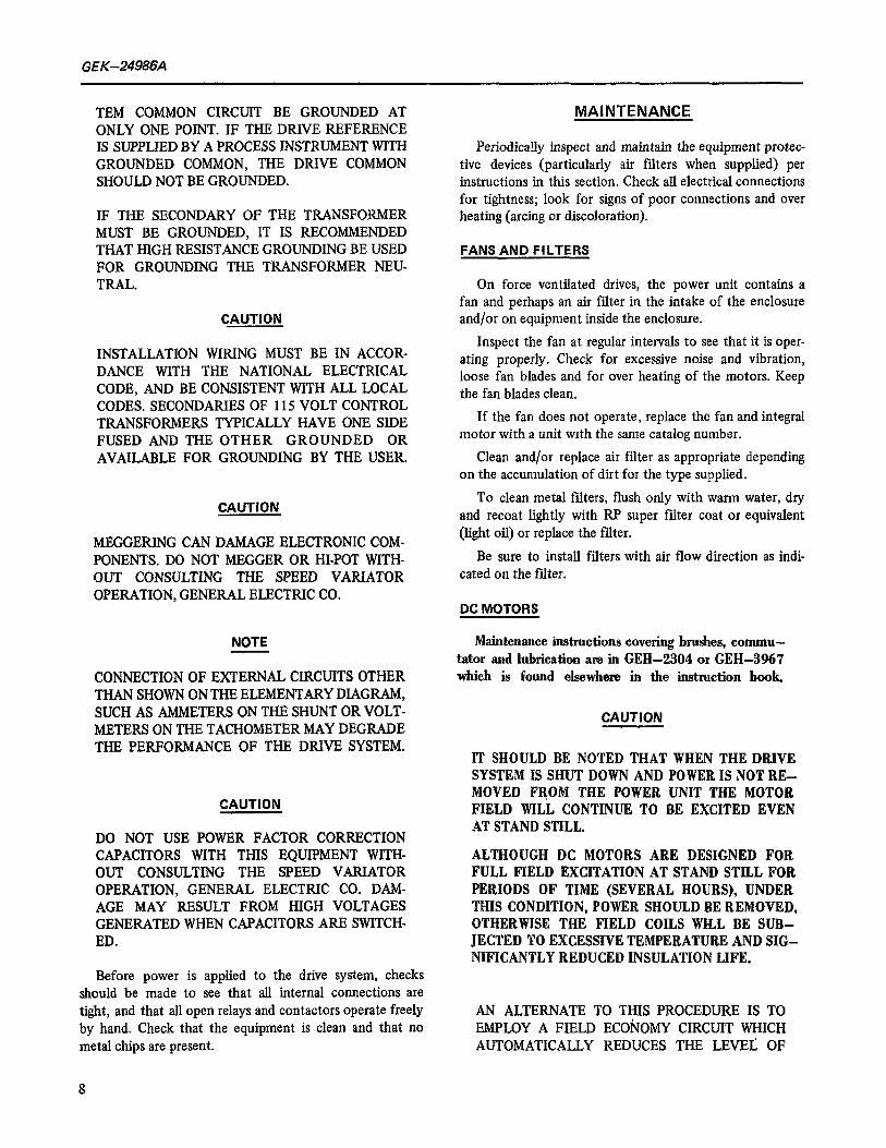
(Photo SV-4951.1)
FIG. 3 VALUTROL - POWER UNIT (DOORS OPEN) (Photo MG-5236-20)
FIG. 4 POWER SUPPLY CARD
11
GEK-24986A
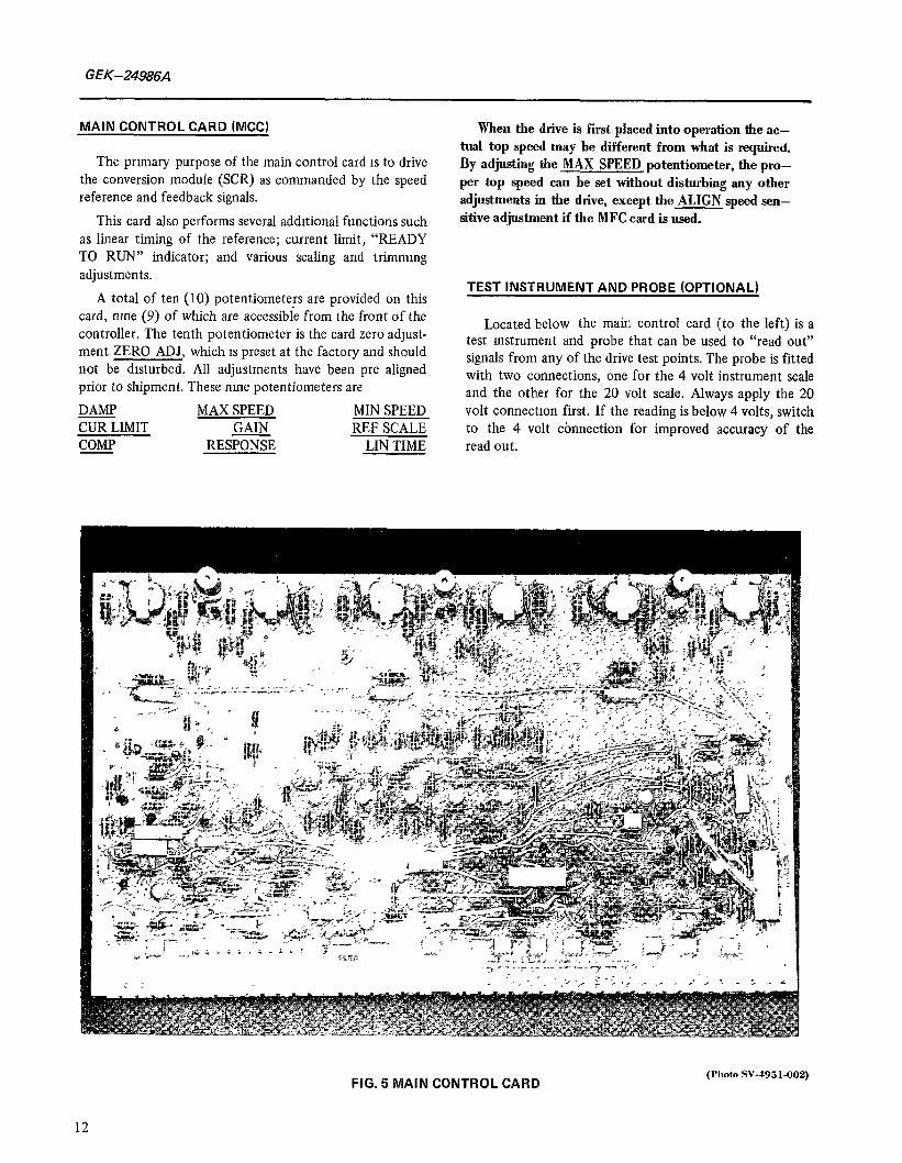
MAIN CONTROL CARD (MCC)
The prrmary purpose of the main control card 1s to drive the conversion module (SCR) as commanded by the speed reference and feedback signals.
This card also performs several additional functions such as linear timing of the reference; current limit, “READY TO RUN” indicator; and various scaling and trimrnmg adjustments.
A total of ten (10) potentiometers are provided on this card, rune (9) of which are accessible from the front of the controller. The tenth potentiometer is the card zero adjust- ment ZERO ADJ, which 1s preset at the factory and should not be disturbed. All adjustments have been pre aligned prior to shipment. These rune potentiometers are
DAMP MAX SPEED MIN SPEED CUR LIMIT GAIN REF SCALE COMP RESPONSE LIN TIME
When the drive is first placed into operation the ac- tual top speed may he different from what is required. By adjusting the MAX SPEED potentiometer, the pro- per top speed can be set without disturbing any other adjustments in the drive, except the ALIGN speed sen- sitive adjustment if the MFC card is used.
TEST INSTRUMENT AND PROBE (OPTIONAL)
Located below the main control card (to the left) is a test mstrument and probe that can be used to “read out” signals from any of the drive test points. The probe is fitted with two connections, one for the 4 volt instrument scale and the other for the 20 volt scale. Always apply the 20 volt connectton first. If the reading is below 4 volts, switch to the 4 volt connection for improved accuracy of the read out.
FIG. 5 MAIN CONTROL CARD (Photo SV-4951.002)
12
et%-24986A
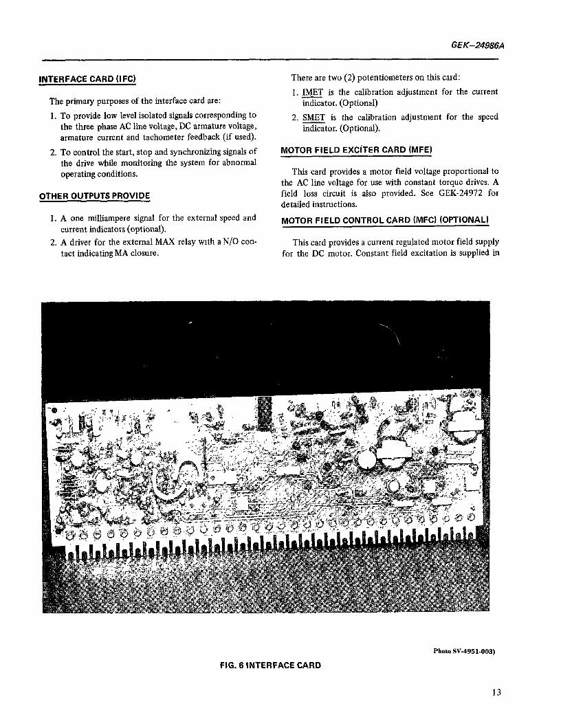
INTERFACE CARD (IFCI
The primary purposes of the interface card are:
1. To provide low level isolated signals corresponding to the three phase AC line voltage, DC armature voltage, armature current and tachometer feedback (if used).
There are two (2) potentiometers on this card:
1. IMET is the calibration adjustment for the current indicator. (Optional)
2. SMET is the calibration adjustment for the speed indicator. (Optional).
2. To control the start, stop and synchronizing signals of the drive while monitoring the system for abnormal operating conditions.
OTHER OUTPUTS PROVIDE
MOTOR FIELD EXCITER CARD (MFE)
This card provides a motor field voltage proportional to the AC line voltage for use with constant torque drives. A field loss circuit is also provided. See GEK-24972 for detailed instructions.
1. A one milliampere signal for the external speed and current indicators (optional).
2. A driver for the external MAX relay wrth a N/O con- tact indicating MA closure.
MOTOR FIELD CONTROL CARD (MFc) (OPTIONAL)
This card provides a current regulated motor field supply for the DC motor. Constant field excitation is supplied in
FIG. 6 INTERFACE CARD
Photos%4951-003)
13

GEK-24966A
(PhotoSV-4951.004)
FIG. 7 MOTOR FIELD EXCITER CARD
the constant torque range as armature voltage is measured from zero to rated voltage. A crossover CROSS adjustment is provided at which time the motor field current is auto- matically decreased thereby increasing the speed of the motor above base speed. In this range the drive characteris- tic changes from constant torque to constant horsepower.
Other functions performed by this card include a moni- tor circuit ‘to detect the loss of tachometer feedback voltage, over speed and loss of motor field. Any of these faults will shut down the drive. A field economy crrcuit automatically reduces the level of motor field excrtation whenever the drive is shut down, thereby avoiding the possibility of excessive temperature (at stand still) and/or reduced insulation life. See GEK-24971 for detailed in- structions.
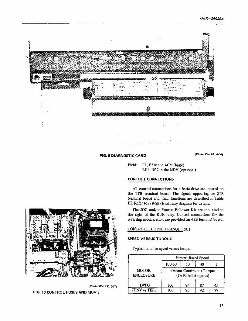
DIAGNOSTIC CARD (DGC) (OPTIONAL)
The diagnostic card performs no function under normal operating conditions but will program the drive into a diagnostic run mode or diagnostic static mode for ease in initial start up and trouble shooting. THIS CARD IS HIGHLY RECOMMENDED.
(PhotoSV-4951-005)
FIG. 8 MOTOR FIELD CONTROL CARD
CONTROL FUSES, MOV5
The signal power for the control is taken from the three phase input through control fuses to the control voltage transformer (not shown on block diagram). The control fuses protect the control transformer and the metal oxide varistors (MOV) protect the power unit from excessive transient over voltage conditions. Three resistance wires which provide line synchronization are connected to the load side of these fuses. The drive will not operate if any one of these fuses are open.
POWER CONNECTIONS
The power connections are the three phase input at Ll, L2, and L3 on the line fuses. An optional circuit breaker can be added ahead of the fuses as shown on the block diagram, Fig. 2. The line fuses remain in the circuit even though an optional circuit breaker is selected.
The DC motor armature and shunt field connection are as follows:
Arm: DAl, DA2 in the ACM (basic) RAI, RA2 in the MDM (optionaD
14
GEK-24986A
FIG. 9 DIAGNOSTIC CARD (Photo SV-4951-006)
Field: F 1, F2 in the ACM (basic) RF 1, RF2 in the MDM (optional)
CONTROL CONNECTIONS
(Photo SV-4951-007)
FIG. 10 CONTROL FUSES AND MOV’S
All control connections for a basic drive are located on the 2TB terminal board. The signals appearing on 2TB terminal board and their functions are described in Table III. Refer to system elementary diagram for details.
The JOG and/or Process Follower Kit are mounted to the right of the RUN relay. Control connections for the reversing modification are provided on 4TB terminal board.
CONTROLLED SPEED RANGE: 20: 1
SPEED VERSUS TORQUE
Typical data for speed versus torque:
1 15
GEK-24986A
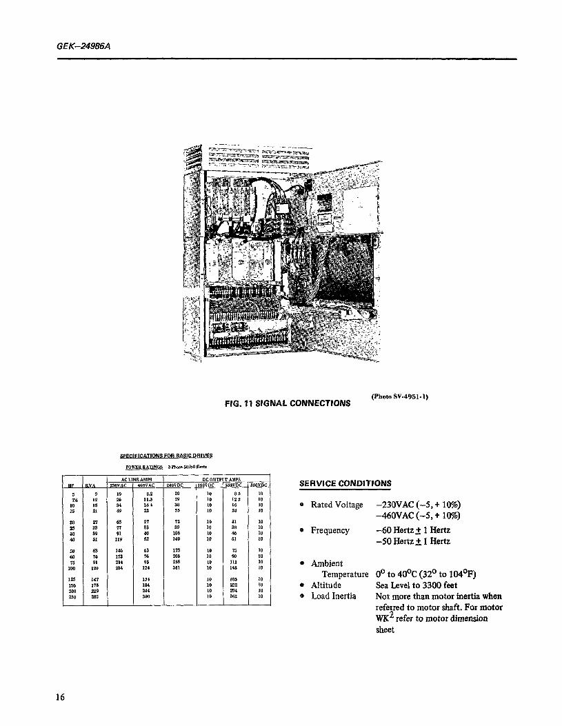
FIG. 11 SIGNAL CONNECTIONS (Photo SV-4951.1)
WTIONS FOR BASIC DRIVES
PowEB RATINGS -a Fllase M/60 He*
26 27 63 2, ,2 10 31 10 25 33 $1 33 89 10 38 IO 30 39 91 40 106 10 46 10 % 51 119 52 140 10 61 IO
50 63 1% 63 173 10 75 10 60 74 173 76 206 10 90 10 '15 91 214 93 255 10 111 10
100 1m 284 124 341 10 148 IO
125 I I 1154 I 147 I 10 I 185 I 10 I
SERVICE CONDITIONS
@ Rated Voltage -230VAC (-5, + 10%) -460VAC (-5, + 10%)
* Frequency -60 Hertz_+ 1 Hertz -50 Hertz k 1 Hertz
l Ambient Temperature 0’ to 40°C (32’ to 104’F)
l Altitude Sea Level to 3300 feet .a Load Inertia Not more than motor inertia when
referred to motor shaft. For motor WK2 refer to motor dimension sheet
16
GEK-24986A
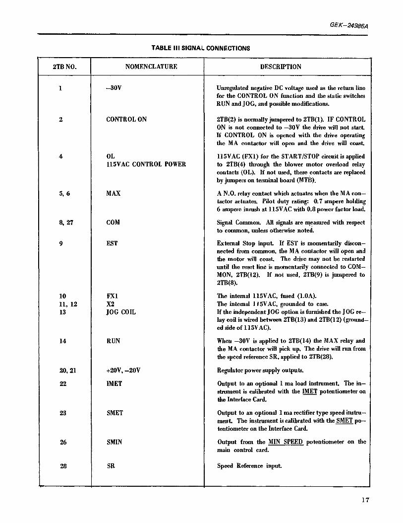
TABLE III SIGNAL CONNECTIONS
2TB NO. NOMENCLATURE DESCRIPTION
1 -30v UnreguIated negative DC voltage used as the return line for the CONTROL ON function and the static switches RUN and JOG, and possible modifications.
2 CONTROL ON 2TB(2) is normally jumpered to 2TB(l). IF CONTROL ON is not connected to -30V the drive wiR not start, If CONTROL ON is opened with the drive operating the MA contactor wiII open and the drive wiR coast.
4 OL 115VAC CONTROL POWER
115VAC (FXl) for the START/STOP circuit is applied to 2TB(4) through the blower motor overload relay contacts (OL). If not used, these contacts are replaced by jumpers on terminal board (MTB).
5, 6 MAX A N-0. relay contact which actuates when the MA con- tactor actuates. Pilot duty rating: 0.7 ampere holding 6 ampere inrush at 115VAC with 0.8 power factor load
8, 27 COM Signal Common. AR signals are measured with respect to common, unless otherwise noted.
9 EST External Stop input. If EST is momentarily discon- nected from common, the MA contactor wiII open and the motor wiR coast. The drive may not be restarted untiI the reset line is momentarily connected to COM- MON, ZTB(12). If not used, 2TB(9) is jumpered to 2TB(8).
10 11, 12 13
FXl
;:G COIL
The internal 115VAC, fused (l.OA). The internal 115VAC, grounded to case. If the independent JOG option is furnished the JOG re- lay coil is wired between 2TB( 13) and 2TB( 12) (ground- ed side of 115VAC).
14 RUN
20.21 +2ov, -20v
22 IMET
When -30V is applied to 2TB(14) the MAX relay and the MA contactor wiU pick up. The drive will run from the speed reference SR, applied to 2TB(28).
Regulator power supply outputs.
Output to an optional 1 ma load instrument. The in- strument is calibrated with the IMET potentiometer on the Interface Card.
23 SMET
26 SMIN
Output to an optional 1 ma rectifier type speed instru- ment. The instrument is calibrated with the SMET po- tentiometer on the Interface Card.
Output from the MIN SPEED potentiometer on the main control card.
28 SR Speed Reference input.
17
GEK-24986A
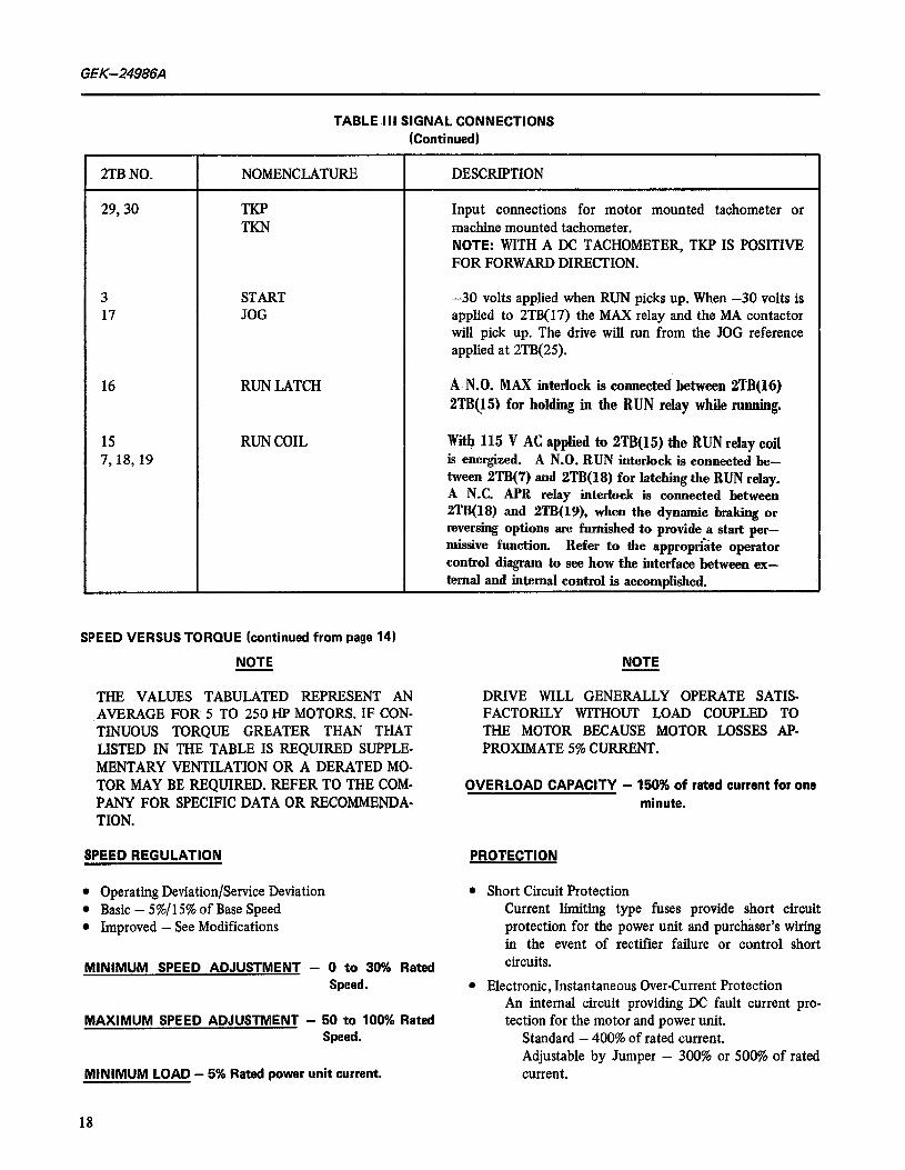
TABLE III SIGNAL CONNECTIONS (Continued)
2TB NO. NOMENCLATURE DESCRIPTION
29,30 TKP TKN
Input connections for motor mounted tachometer or machine mounted tachometer. NOTE: WITH A DC TACHOMETER, TKP IS POSITIVE FOR FORWARD DIRECTION.
3 START 17 JOG
-30 volts applied when RUN picks up. When -30 volts is applied to 2TB(17) the MAX relay and the MA contactor will pick up. The drive will run from the JOG reference applied at 2TB(25).
16 RUN LATCH A-N.O. MAX interlock is connected between 2TB(16) 2TBQ5) for holding in the RUN relay while running.
15 7,18, 19
RUN COIL With115 V AC applied to 2TB(15) tbe RUN relay coil is energized. A N.O. RUN interlock is connected be- tween 2TB(‘7) and 2TB(l8) for latching the RUN relay. A N.C. APR relay interlock is connected between 2TB(18) and 2TB(19), when the dynamic braking or reversing options are furnished to provide a start per- missive function. Refer to the appropri&e operator control diagram to see how the interface between ex- ternal and internal control is accomplished.
SPEED VERSUS TORQUE (continued from page 14)
NOTE NOTE
THE VALUES TABULATED REPRESENT AN AVERAGE FOR 5 TO 250 HP MOTORS. IF CON- TINUOUS TORQUE GREATER THAN THAT LISTED IN THE TABLE IS REQUIRED SUPPLE- MENTARY VENTILATION OR A DERATED MO-
DRIVE WILL GENERALLY OPERATE SATIS- FACTORILY WITHOUT LOAD COUPLED TO THE MOTOR BECAUSE MOTOR LQSSES AP- PROXIMATE 5% CURRENT.
TOR MAY BE REQUIRED. REFER TO THE COM- PANY FOR SPECIFIC DATA OR RECOMMENDA- TION.
SPEED REGULATION PROTECTION
l Operating Deviation/Service Deviation l Basic - 5%/ 15% of Base Speed l Improved - See Modifications
MINIMUM SPEED ADJUSTMENT - 0 to 30% Rated Speed.
MAXIMUM SPEED ADJUSTMENT - 50 to 100% Rated Speed.
MINIMUM LOAD - 5% Rated power unit current.
OVERLOAD CAPACITY - 150% of rated current for one minute.
l Short Circuit Protection Current limiting type fuses provide short circuit protection for the power unit and purchaser’s wiring in the event of rectifier failure or control short circuits.
l Electronic, Instantaneous Over-Current Protection An internal circuit providing DC fault current pro- tection for the motor and power unit.
Standard - 400% of rated current. Adjustable by Jumper - 300% or 500% of rated current.
18
GEK-24986A
l Transient overvoltage protection by metal oxide vanstors (MOV)
l Overload Protection 150% of rated current for one minute. Motor mounted Thermal Switch and/or Electronic Timed over current circuit. (Optional)
l Phase Sequence Protection Initiates the fault function. The “Ready to Run” light will not turn on for incorrect phase sequence.
l Loss of Phase Protection The “Ready to Run” light turns off and a controlled drive system shut down occurs due to the loss of one or more phases.
l Electronic Motor Field Loss Protection Adjustable on both the MFE and MFC card.
DC MOTOR VOLTAGES
23QVAC Input - 240VDC Armature, 15OVDC Field 460VAC Input - 550VDC Armature, 300VDC Field
CONTROL POWER (Push buttons)
Fused 115VAC Isolated
ACCELERATION/DECELERATION CONTROL
Linear Time Rate, Single Adjustment 0.3 to 60 second range
Current Limit Adjustment 20 to 150% of rated current.
JOG AT MINIMUM SPEED
Adjustable - 0 to 30% speed with RUN/JOG Selector Switch.
INPUT SIGNAL REQUIREMENTS -5V to -20V DC at 1.3MA (with ‘lo/o or less ripple)
l Voltage Follower - Signal greater than 20VDC requires dropping resistor. Maximum level not to exceed 25ovDc.
l Instrument Follower - Modification provides for O-5, 1-5, 4-20, and IO-50 rnilliamp signals.
SERVICE FACTOR - 1.0
EFFICIENCY
AC to DC at Rated Output Power Unit - Approximately 97% Drive - 80 to 85% depending on rating selected.
POWER FACTOR - At Rated Output 77 to 88% depend- ing on voltage selected.
POWER UNIT ENCLOSURE -
Standard - Nema 1, Ventilated Optional - Nema 12, See Modifications.
STABILITY ADJUSTMENTS (Card Mounted)
Gain, Response, Damping and IR Compensation.
EXTERNAL POTENTlOMETERS
Speed Adjust - 2.5K, 2W Current Limit Adjust -lK, 2W (optional)
MODlFlCATlONS
PYNAMIC BRAKING
Drive system shall be capable of braking a load (whose inertia equals that of the motor, referred to the motor shaft) at an initial current of 150% of rated armature cur- rent from full speed to standstill, three times in rapid suc- cession with the dynamic braking resistor initially at am- bient temperature.
REVERSING (SELECTIVE ROTATION)
Selective Rotation is provided by magnetic contactors. Armature reversing is provided on Valutrol Drives from 5 to 30 HP at 230VAC; 5 to 60 HP at 460VAC. Above these ratings, motor field contactors are employed to perform the selective rotation function.
IMPROVED SPEED REGULATION
Speed regulation of the basic voltage regulated drive with IR drop compensation is 5% “operating” and 15% “service” deviation. By the addition of a type AN, AC tachometer for a speed feedback signal, speed regulation can be improved to 1% “operating” and 2% “service” deviation.
CONSTANT HORSEPOWER SPEED RANGE
All Valutrol Drives include a constant voltage exciter (MFE) with field loss protection. If operation above base speed (motor field weakening range) IS required, a motor field control (MFC) will be provided. See General Descrip- tion.
The MFC function includes: B Motor Field Programming e Motor Field Current Regulation
19

GEK-24986A
l Tachometer Monitor l Max Field, Min Field and Field Loss Adjustments. l Motor Field Economy - Designed to reduce motor
field excitation at standstill.
NOTE
A TACHOMETER GENERATOR IS REQUIRED WHEN THE CONSTANT HORSEPOWER SPEED RANGE IS SELECTED, EITHER FACTORY IN- STALLED OR IN “KIT” FORM.
AC LINE CIRCUIT BREAKER/SWITCH
Au AC liue disconnect switch with external opera- ting handle mecbanicaUy interlocked with the enclosure doOr may be ordered for aU drive ratings. Enclosure w-31 be increased on basic drives only. Note that the modification compartment added will accommodate my or all control modifications offered. The AC he fuses are always retained.
BLOWER MOTOR CONTROL
All motor ventilation blowers operate from the main AC line contactor and require the addition of fuses and a ther- mal overload relay. These components are mounted in the modification compartment.
POWER UNIT ENCLOSURES
NEMA 1 ventilated wall mounted enclosures are stand- ard up to 40 HP at 230VAC and 100 HP at 460VAC.
NEMA 1 ventilated floor mounted enclosures are stand- ard 50 HP and above at 230VAC and 125 HP and above at 460VAC. NEMA 1 ventilated floor mounted enclosures are available as a modification 40 HP and below at, 23OVAC and 100 HP and below at 460VAC.
NEMA 12 enclosure. The normal wall mounted enclos- ure will be mounted in a large NEMA 12 enclosure with adequate surface area to dissipate power unit watts to a 40°C (104’F) ambient temperature. This arrangement is available up to 60 HP at 46OVAC.
ISOLATION TRANSFORMERS
Isolation transformers are available for all Valutrol GP ratings in NEMA 1 enclosures for separate mounting by the purchaser. All transformers are furnished with l-5% full rated tap above and l-5% full rated tap below rated primary voltage, UL listed and labeled as follows: Primary Voltage 23OV- 46OV- 575v-
Secondary Voltages 23OV-Y 23OV-Y 23OV-Y 46OV-Y 46OV-Y 46OV-Y
20
TEST INSTRUMENT
A test instrument and probe is available for mountbg in the main control module allowing direct reading of test points on the main control card.
DIAGNOSTIC PANEL
Most “set up” adjustments are made in factory test; however the diagnostic panel is highly recommended option for pre-start up check and maintenance during the life of the equipment.
Panel provides a “mode” selector (normal, diagnostic static and diagnostic run) with speed and current reference potentiometers.
SPEED INDICATOR - 3%” Instrument Scale: O-100% speed (Does not require a tachometer generator).
LOAD INDICATOR - 3%” Instrument
Scale: O-150% load (Red lined, lOO-150%)
VOLTAGE FOLLOWER - NOTE: A Manual/Auto selector switch may be required.
INSTRUMENT FOLLOWER - NOTE: A Manual/Auto selector switch may be required.
PRESET JOG SPEED
Provides a separate preset jog speed (without timing) and includes a jog potentiometer and relay.
REMOTE CURRENT LIMIT
Provides a separate potentiometer and knob in an operator’s station for remote current limit (torque) ad- justment.
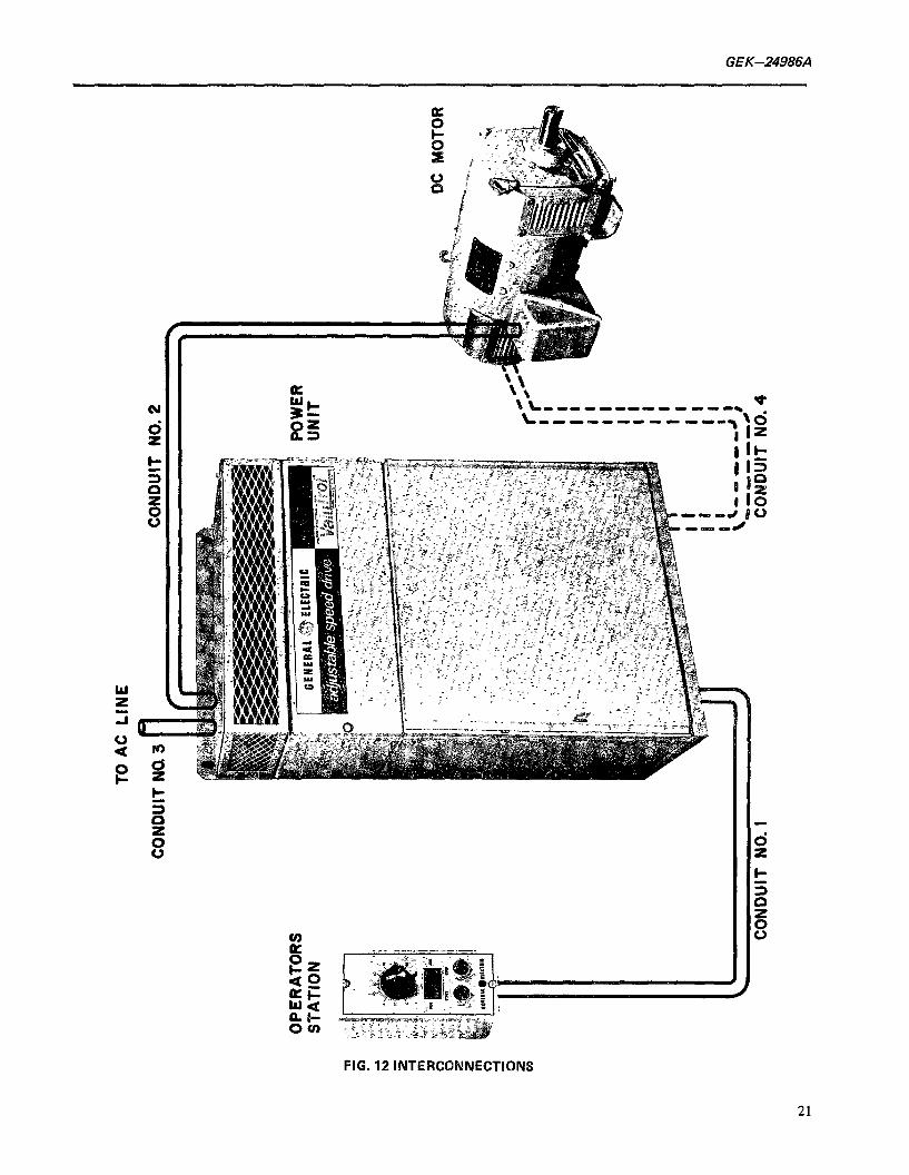
INTERCONNECTION
GENERAL
All internal electrical connections between devices in the power unit have been made by General Electric Company. Check for proper jumper connections on termihal boards 2TB, according to the operator control circuit arnployocl.
lNTERCONNECTlON OF DRIVE COMPONENTS
Electrical connections are required between the power unit and motor and between the power unit and operator’s
GEK-24986A
E
Sk 4 -u-------------*
h7 L ----------I-m \d
FIG. 12 INTERCONNECTIONS
21
GEK-249864
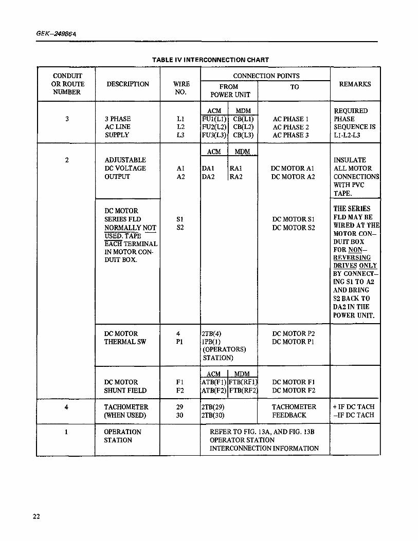
TABLE IV INTERCONNECTION CHART
CONDUIT OR ROUTE NUMBER
DESCRIPTION WIRE NO.
CONNECTION POINTS
FROM TO POWER UNIT
REMARKS
3 3 PHASE AC LINE SUPPLY
Ll L2 L3
ACM MDM FUl(L1) CB(L1) FU2(L2) CB(L2) FU3(L3) CB(L3)
AC PHASE 1 AC PHASE 2 AC PHASE 3
REQUIRED PHASE SEQUENCE IS Ll -L2-L3
2 ADJUSTABLE DC VOLTAGE OUTPUT
Al A2
ACM MDM
DA1 RAl DA2 RA2 I
DC MOTOR Al DC MOTOR A2
INSULATE ALL MOTOR CONNECTION! WITH PVC TAPE.
DC MOTOR SERIES FLD Sl NORMALLY NOT S2 USED. TAPE - m TERMINAL IN MOTOR CON- DUIT BOX.
DC MOTOR S 1 DC MOTOR S2
THE SERIES FLD MAY BE WIRED AT THI MOTORCON- DUITBOX FOR NON- REVERSING DRIVESONLY BYCONNECT- ING SlTO A2 ANDBRING S2 BACK TO DA2INTHE POWERUNIT.
_
DC MOTOR 4 THERMAL SW Pl
2TB(4) lPB( 1) (OPERATORS) STATION)
DC MOTOR P2 DC MOTOR Pl
, ACM MDM DC MOTOR Fl ATB(F 1) FTB(RF 1; DC MOTOR Fl SHUNT FIELD F2 ATB(F2) FTB(RF2; DC MOTOR F2
4 TACHOMETER 29 2TB(29) TACHOMETER t IF DC TACH (WHEN USED) 30 2TB(30) FEEDBACK -IF DC TACH
1 OPERATION REFER TO FIG. 13A, AND FIG. 13B STATION OPERATOR STATION
INTERCONNECTION INFORMATION
22
GEK-24986A
station as shown in Fii. 12. This illustration shows the conduit runs or routes required for these interconnec- tions. Table IV shows the numher of wires required for each conduit run as shown in Fig. 12. Wire sizes for interconnections should he selected in accordance with the ampere requirements shown on page 16 and in accordance with local and national electrical codes. In- stall conduit runs 1 thru 3 in accordance with this tabulation.
It is recommended thaL the drive system common circuit be grounded at only one point. This means that if the drive reference is supplied by a process instrument with grounded common, the drive common should not be connected to ground except through the process instrument.
If the secondary of the isolation transformer (optional) must be grounded, it is recommended that high resistance grounding be used for grounding the transformer neutral. It is recommended that the power unit, operator’s station and DC motor enclosures be grounded in accordance with NEC or local code requirements.
AC POWER CONNECTION
1. Make certain that the input voltage and frequency of the available power supply agree with the rating on the power unit nameplate located on the inside of the power unit enclosure. If an isolation transformer is to be used, refer to step 4.
2. Electrical codes generally require the use of a fused disconnecting switch or circuit breaker in the AC power line, ahead of the power unit and transformer (if used). This disconnecting device also provides a convenient method for removing field excitation from the-DC motor when the drive is not in use, and allows complete removal of power for routine main- tenance and inspection. The disconnecting switch and fuse (or circuit breaker) should be selected in accord- ance with theNationalElectrical Code and/or local code requirements based on the power input data on the Vahrtrol Drive nameplate. These data are sum-
23

GEK-24986A
A. STANDARD STATION B. PUSHBUTTON JOG STATION
WIRE POWER NO. UNIT
3 2TB(3)
7 2TB(7)
14 2TB( 14)
15 2TB(l5)
16 2TBc16)
17 1 2TB(17)
18
I
2TB(18)
19 1 2TB(19) I 21 2TB(21) TW) TN3 TN3 TN?) TW 26 2TB(26) TN11 TW) TWO TN0 ‘Wl)
13 1 2TB(13)
2TB JUMPERS
CIRCUIT
CONNECTION POINTS
lPB(2), 2PB( 1) lPB(2), 2PB(l) lPB(2) lPB(2), 2PB(l), lPB(2)
3TB( 1)
1 2PB(l), lSW(3) 1 (2PB(1),3PB(l:
FIG. 438 INTEWCONNECTBON OF OPERATOR’S STATION
24

GEk--24986A
C. STANDARD REVERSING STATION D. PUSHBUTTON JOG REVERSING STATION
21. 2TB(21) 26 2TBf261
lSW(3) TW TB(l)
3PB( 1) TJW) TBf 1)
\I
28 2TB(28) TW) TB(2) Pl ,, THSW(P1) _ .l@ It j2TB (10) I-
lPB(1) IPB(1) 2SW(2) 2sw-
13 2TBC 13) ~PB,JJ I E-i L
41 4TB(lj 2SW( 1) 2SWii) 42 4TB(2) 2SW(6)* 2s W(6)” 43 4TB(3) 2SW(3) 2SW(3) 44 4TB(4) 2SW(4)* 2SW(4)* 45 4TB(S) 2SW(5)” 2SW(5)*
*NOT REQUIRED WITH ARMATURE REVERSING.
FIG. 136 INTERCONNECTION OF OPERATOR’S STATION (REVERSING)
25
GEK-24986A
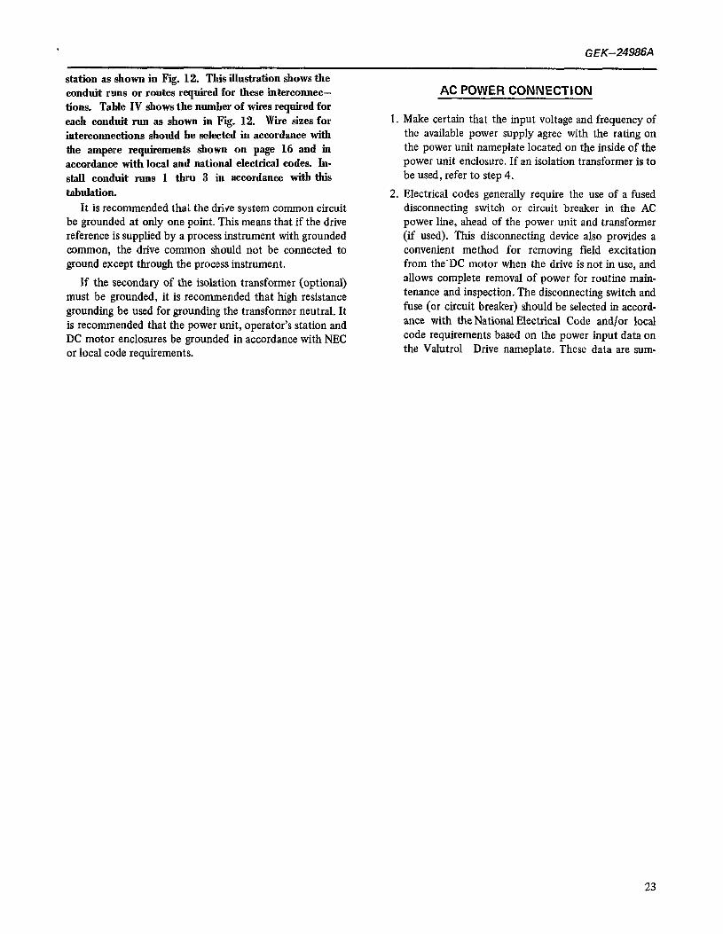
E. AUTO/MANUAL STATION ‘-rir- : L’ &i+ “.lCunn 1,
15 ZTB(15): 2PB(3)
18 2TBll8) 1 PB(2)
19 Pl
2TB(19) 2PB( 1) THSW( 1) lPB(I)
MRl PCF(MR1) 21 2TB(2 1)
26 2TB(26) 28 2TB(28) ASR PCF(ASR)
TB(3)
TN0 1W2), (5) lSW3),(6)
TB(21, ISW(l) (4) PCP 1 PCF(PCP) 1 EXT
PSW PCF(PSW) EXT
27 2TB(27) 1 EXT I
2TB JUMPERS (3)toU4) (7)to(16)
CIRCUIT FIG. 34
3N POINTS JTO/MANUAL STATION
;-
TB(2), lSW(I) (4) TB(3), lSW(2) (4)
EXT EXT
EXT - EXTERNAL SIGNAL SOURCE OR SERIES RESISTOR. IF DYNAMIC BRAKING IS NOT USED JUMPER 2TB( 18) TO 2TB( 19).
FIG. 13C INTERCONNECTION OF OPERATOR’S STATION
26
GEK-24986A
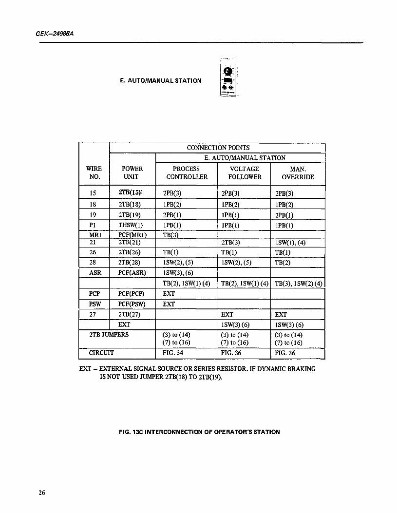
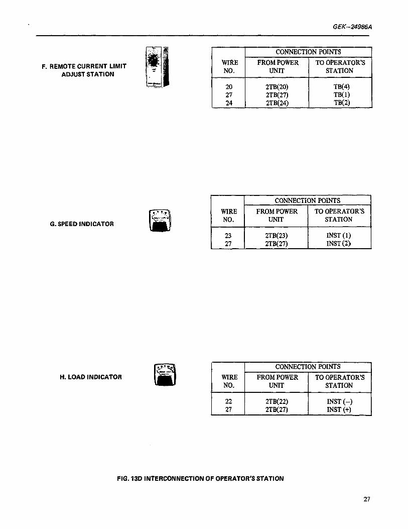
F. REMOTE CURRENT LIMIT ADJUST STATION
WIRE NO.
CONNECTION POINTS FROM POWER TO OPERATOR’S
UNIT STATION
G. SPEED INDICATOR
20 2TB(20) TN4 27 2TB(27) TN0 24 2TB(24) TB(2)
H. LOAD INDICATOR
23 2TB(23) INST (1) 27 2TB( 27) INST (2)~
WIRE NO.
22 27
CONNECTION POINTS FROM POWER TO OPERATOR’S
UNIT STATION
2TB(22) INST (-) 2TB(27) INST (+)
FIG. 13D INTERCONNECTION OF OPERATOR’S STATION
27

G/X-2498&-l
(JOG SELECTOR NOT USED) 2PB
START RUN - (151
‘IO) (716
2PB S_TANDARD STATION
3PB START - (13)
PUSH BUTTON JOG
JOG
A FOR JOG AT MIN SPEED ADD JUMPER JOG REFERENCE IF ZERO MIN SPEED IS REQUIRED
TERMINAL BOARD POINTS ’ 1 ARE ALL ON 2TB. ---------INTERNAL WIRING
FIG.IJE CONTROL CIRCUITS WITHOUT DYNAMIC BRAKING OR REVERSING
28
GEK-24986A
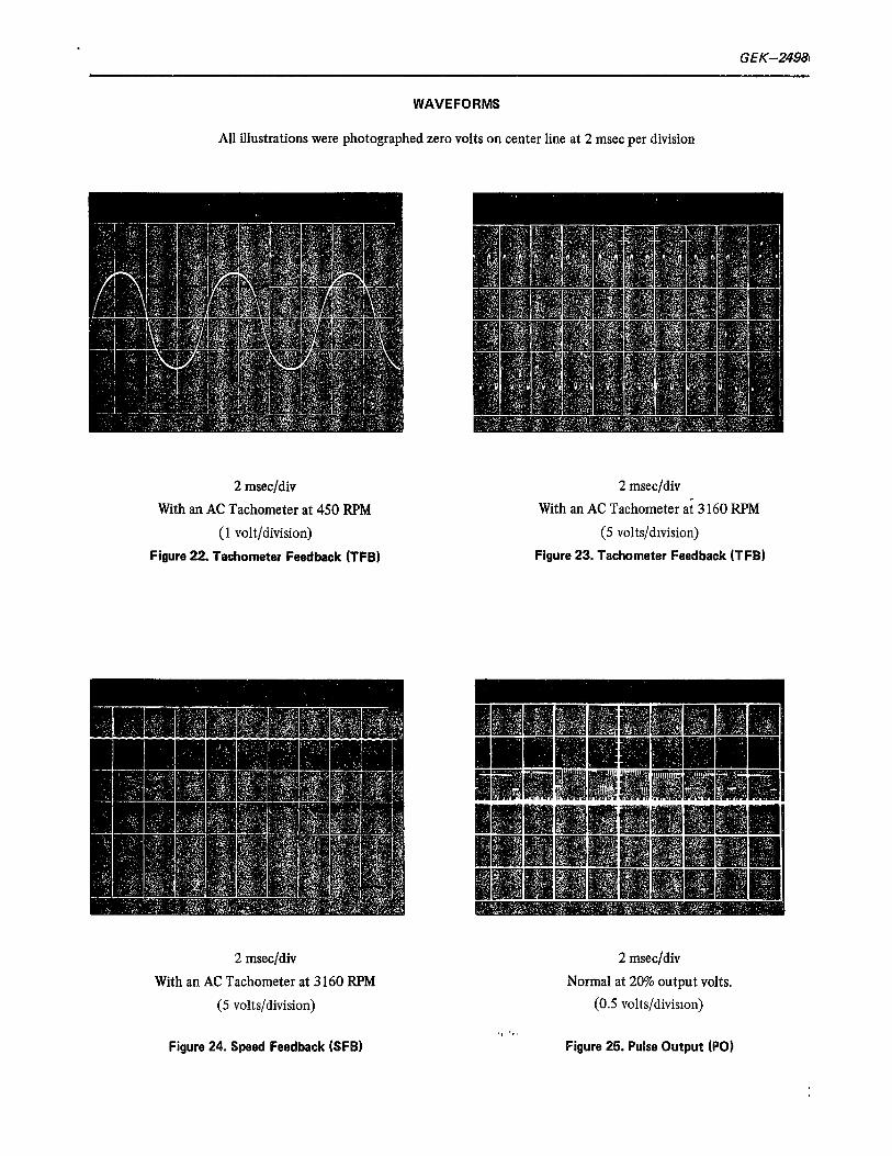
marized on page 16 to aid in the selection of dis- connecting devices, fuses and wire sizes. The circuit
/ hreakeroption provides disconnect of all power to the power unit, motor and operator’s station.
3. AC power connections from any external discon- necting device to the power unit may now be made in accordance with conduit run 3 as shown in Table IV.
4. If the available power supply is other than that shown on the power unit data nameplate it will be necessary to use a line transformer between the disconnecting device and the power unit. This transformer will be separately mounted by the purchaser. The appendix provides complete information on isolation trans- formers for use with Valutrol Drives, including required KVA catalog numbers, weights and dim- ensions.
FINAL Cl-;‘=-CK
After all electrical connections have been made, com- plete the installation as follows:
1. Recheck all connections using the interconnection chart Table IV. Recheck the transformer connections (if used) and connections to the disconnecting device (if used).
2. Re-assemble the operator’ station. Carefully dress the interconnecting wire into the back of the station so that the device assembly may be installed. Keep the wires away from sharp edges and do not force the device assembly into place. Replace the station cover.
3. Recheck the motor connections, carefully tape and insert them in the conduit box. Replace the conduit box cover.
4. Install protective fuses in the AC disconnect (if used).
START UP
Every Valutrol DC SCR drive has been factory tested and is ready to operate provided the external power and control connections have been properly made and the following step by step procedures are followed:
1. Verify that the terminal hoard screws are tight.
2. Verify that incoming power is the proper voltage and the incoming wiring is complete and correct.
3. if the diagnostic option is furnished set tbe diag- nostic switch to its NORMAL (center) position. Apply power to the drive. If the green “Ready to Run” light located on the lower left hand corner of the main control card (MCC) is not illumina- ted, press and release the RESET pushbutton on the panel below. If the light does not turn on,
4.
5.
6.
Verify that the reference voltage, SR, from 2TB(28) to 2TB(27) is -20 volts with the external speed ad- just potentiometer turned fully clockwise. Return the potentiometer to zero (fully CCW). If the diagnostic card option is provided, set the local speed reference (LOC REF) potentiometer to its center position and switch into the diagnostic run (DIAG RUN) position. The MA contactor should pick up. Slowly turn the LOC REF poten- tiometer away from the control until the motor starts to rotate. If the tachometer feedback. option was selected verify that a positive speed feedback signal appears on the SFB test point, located on the bottom of the main control card (MCC) on the left hand side. Check motor rotation. Check tachome- ter polarity. With a DC tachometer TKP (2TB-29) is positive for forward rotation. Turn the LOC REF potentiometer back to the center position and switch to NORMAL. If the motor rotation was incorrect, remove power and interchange the motor field connections Fl (or RFl) and F2 (or RF2) on ATB terminal hoard. If no diagnostic card is available set the external speed reference potentiometer to zero (full CCW) and press the START pushbutton. The MA con- tactor should prck up. Slowly turn the speed refer- ence CW until the motor starts to rotate. Check motor rotation. If incorrect, remove power and interchange the motor field leads Fl and F2 (or RF1 and RF2) on ATB termmal board
7. Run the drive from the external speed reference up to top speed. Adjust MAX SPEED as may be requir- ed.
8. Close and secure the front door of the power unit.
the most probable cause is incorrect incoming phase rotation. Remove power, reverse any two of the incoming AC power leads and repeat.
SEQUENCE OF OPERATION
POWER APPLIED
The control transformer is energized through its primary fuses. The fans (if supplied) will come on.
The power supply card @‘SC) is energized and the DC outputs (9~20 volts) are applied through their fuses to the rest of the cards. All readings carry a tolerance of +10% when read on the built in instrument.
The motor field supply is energized. Refer to the motor field supply instructions for details.
29
GEK-24986A
TABLE V FAULT CONDITIONS
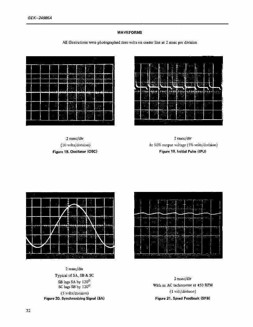
A fault has occured if the READY TO RUN light is off. The conditions that can initiate a fault are as follows:
1.
2.
3.
4.
5.
6.
** 7.
8.
** 9.
10.
* 11.
12.
13.
14.
15.
* 16.
** 17.
No three phase power to the Fuses (or optional Circuit Breaker)
Circuit breaker is open, or AC power fuse blown.
Control fuse is open.
Power supply plus or minus DC fuse is open.
Loss of an incoming phase.
Incorrect phase rotation.
Instantaneous overcurrent (IOC) level exceeded.
Timed over current (TOC) - electronic.
Loss of motor field.
External Fault Stop momentarily released from Common.
Other special functions to System Trip (SYS) or External Fault Stop inputs.
System Trip input (SYS) momentarily connected to +lO volts.
RESET button held depressed or RSET input held connected to Common.
Diagnostic mode selected with the motor rotating.
Oscillator failed “on”.
Tachometer fault (loss of tachometer signal), DC output open, or incorrect ALIGN adjustment.
Overspeed
* May not be provided. Refer to instructions on Motor Field Supply and System elementary diagram. ** Can be caused by LOC REF and CUR LIM settings in Static Diagnostic mode.
After the fault condition has been cleared and the motor has come to standstill,. the drive can be RESET by any of the following three methods:
1. Momentarily remove the three phase power and re-apply.
2. Push the RESET button
3. Momentarily connect RSET to common.
30

GEK-24986A
WAVEFORMS
All illustrations were photographed zero volts on center line at 2 msec per division
2 msec/div
At low current level (1 volt/division)
Figure 14. Current Feedback (CFB) (Inverted)
2 msec/dlv
At Continuous current (1 volt/division)
Figure 15. Current Feedback (CFB) (Inverted)
2 msec/dlv
At low current and 50% output (5 volts/division)
Figure 16. Voltage Feedback h/FBI (Inverted)
2 msec/div
At continuous current and 50% output volts) (5 volts/division)
Figure 17. Voltage Feedback (VFB) (Inverted 1
31
GEK-24986A
WAVEFORMS
All illustrations were photographed zero volts on center line at 2 msec per division
2 msecjdiv
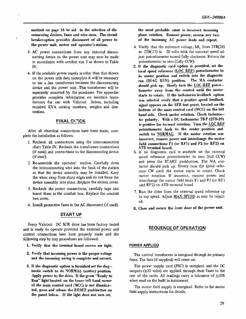
(10 volts/division)
Figure 18. Oscillator (OSC)
2 msec/div
At 50% output voltage (5% volts/division)
Figure 19. Initial Pulse (IPU)
2 msec/div
Typical of SA, SB & SC
SB lags SA by 120’ SC lags SB by 120’
(5 volts/division) Figure 20. Synchronizing Signal &A)
2 mseq’div
With an AC tachometer at 450 RF’M
(1 volt/division)
Figure 21. Speed Feedback (SF61
32
G EK-24984
WAVEFORMS
All illustrations were photographed zero volts on center line at 2 msec per division
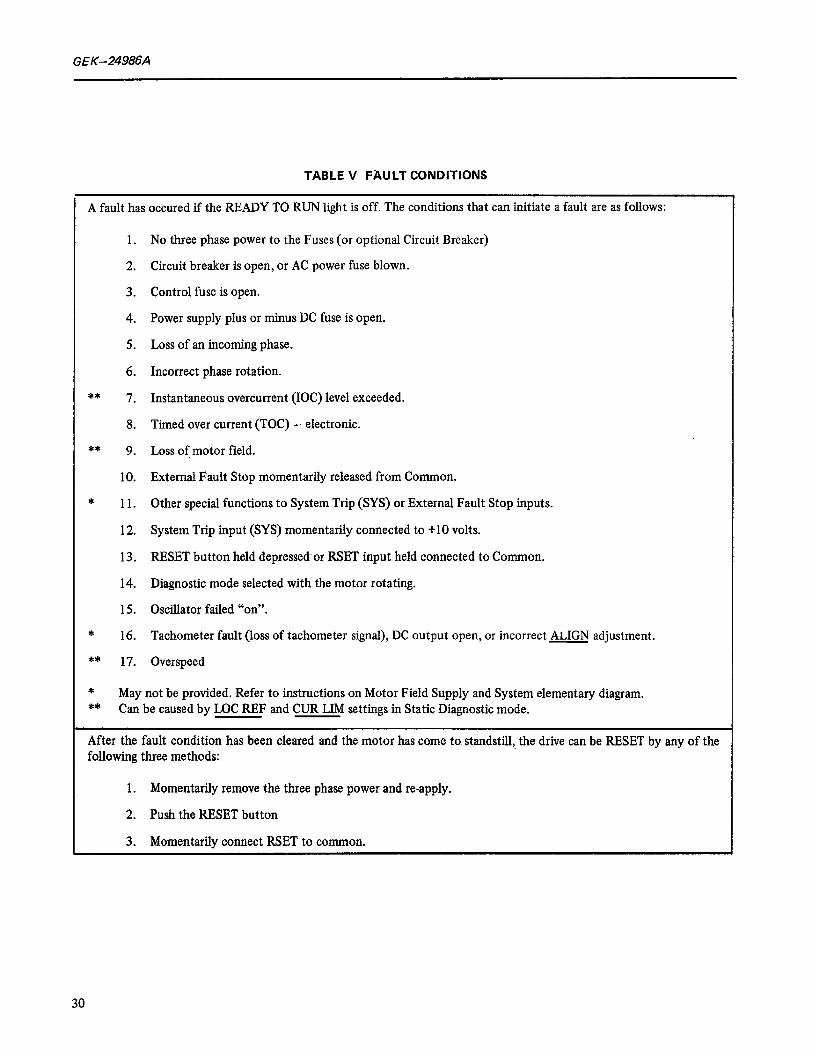
2 msecjdiv
With an AC Tachometer at 450 RPM
(1 volt/division)
Figure 22. Tachometer Feedkck (TFB)
2 msec/div
With an AC Tachometer ai 3 160 RPM
(5 volts/dnision)
Figure 23. Tachometer Feedback (TFBI
2 msec/div
With an AC Tachometer at 3 160 RPM
(5 volts/division)
2 msec/div
Normal at 20% output volts.
(0.5 volts/division)
Figure 24. Speed Feedback (SFB) Figure 25. Pulse Output (PO)

GEK-24986A
WAVEFORMS
All illustrations were photographed zero volts on center line at 2 msec per division
2 msec/div.
With one SCR gate lead open, 50% output volts.
(0.5 volts/division)
Figure 26. Pulse Output (PO)
NOTE
IF THE MOTOR FIELD REVERSING OPTION IS PROVIDED, THE MOTOR FIELD WILL NOT BE ENERGIZED UNTIL THE DRIVE IS STARTED.
IF NO FAULTS HAVE BEEN DETECTED BY THE MONITORSECTION OF THE INTERFACECARD (IFC) THE “READY TO RUN” INDICATOR ON THE- MAIN CONTROL CARD WILL ILLUMI- NATE. TABLEVTABULATESTHEFAULTCON- DITIONS WHICH ARE MONITORED.
The oscillator will start and the synchronizing signals SA, SB, SC will measure 8.5 volts RMS (210%) See Fig. 18 and 20.
START
The RUN relay will pick up when the start pushbutton is pushed.
SWITCH LOGIC
'J"e RUN (or JOG) input poiut on the main control card (MCC) will be switched from +30 volts to -30
volts. The MA control line MAC from the main control card
@ICC) to the interface card (IFC) will be pulled down to -20 volts.
34
2 msec/div
Gate to Cathode Firing Signal IG-IC, with 50% output voltage continuous current. Typic&l of all six signals.
(5 volts/division)
FIG. 27
Gate to Cathode Firing Signal (IG-IC)
The interface card (IFC) checks that no faults exist and that “control on” is connected to -30 volts before apply ing power to the coil of the MA pilot relay MAX.
MAX picks up, releasing the preconditioning signal PRE from common and applies power to the coil of the MA contactor.
When PRE is released from common, it switches to -4 volts which will release the main control card precondition- ing after approximately 80 milliseconds.
Releasing preconditioning allows the drive to send firing pulses to the gates of the SCR’s in the conversion module and allows the normal signal flow to occur.
SIGNAL FLOW
If the RUN is switched, the reference at SR is applied to the linear time section. The timed reference output TR wiN ramp to a voltage proportional to SR. The RRF SCALE adjustment is used to set TR to -10.0 V&S when the input at SR is set for top speed. The time for TR to ramp from 0 to 10 volts is adjustable from 0.3 to 60 seconds with the LIN TIME adjustment. See jumper table for the MCC card. (Ranges 0.3 to 6 sec. or 2 to 60 sec.}
GEK-24986A
The external tachometer signal {if used) or the in1 ternal CEMF signal must he selected by two (2) jumpers on the interface card (IFC) to provide a speed feedback signal (TFB) to the speed feedback section on the main control card (MCC) where the signal is rectified (if re- @red). The output of the speed feedback section is SFB and will be 10 volts at top speed. MAX SPEED is adjusted to make the actual top speed correspond to the desired top speed. (See Fii. 21 and 24)
Ine rimed reference TR, or the JOG reference, JOGR, and the speed feedback, SFB are summed by the regulator error amplifier. The error amplifier output EAO will be at low voltage (nearly zero) when the drive is regulating speed. EAO will not be low when the drive speed is changing. The gain of the error amplifier is set with the GAIN adjustment. The GAIN is used primarily to improve the response of the drive%%e constant horsepower region when the motor field supply is a motor field control (MFC) card.
To maintain good speed regulation the error ampli- fier output (EAO) is fed into the integrator. The out- put of the integrator is the reference, DR, to the driv- er. The response of the control below base speed is set with the RESPONSE adjustment. There is a limit; how- ever, to how responsive a drive may be set. Stability of the drive is decreased as its response is increased. If the MFC card is used, the response is desensitized when the drive is operating in the weak field mode (constant horsepower). DO NOT ADJUST RESPONSE DURING THIS MODE OF OPERATION.
To protect the system a current limit section is pro- tided. The limit section output, CLF, drives the regu- lator integrator and will override the error amplifier. The current limit- is set with the CUR LIMIT adjust- ment. Typically current limit is set at 150% of the motor nameplate or 3.25 volts current feedback, CFB.
The counter EMF signal, CEMF, is developed on the main control card (MCC) by subtracting a signal propor- tional to the IR drop of the motor from the voltage feed- back, VFB. This is set with the
The driver reference DR, the voltage feedback, VFB and the damping adJUstment QAIvfF’ are summed at the output of the driver. The driver converts this error to pulse trains which drive the SCR (Thyristor) gates in such a manner as to maintain the motor voltage proportional to the driver reference. The damping adjustment DAMP controls the response of the driver. Generally speaking DAME is used only to quiet small oscillations which occur in the current under light load conditions. Too much damping will slow down the system response and tend to cause over shoot.
The driver provides a signal IPU to the oscillator on the interface card (IFC) to generate an initial pulse at the exact point in time that an SCR is to be fired. See Fig. 19.
TWO driver monitor points are available, PCR and PO. PCR is the phase control reference which causes the output PUISCS trams to phase shift in time with respect to the AC line. As the driver error voltage, DE, changes from zero to -12 volts, the phase control reference, PCR, changes from -4 volts to +4 volts and the output PUISW will shift from full off to full on. PO is used to monitor the pulse outputs to the SCR’s. The PO signal will vary as speed is increased, but the shape and am- plitude should repeat every 60° (2.8 msec) See Fii. 25 and 26.
STOP
There are two stop sequences; normal stop and fault stop.
In either case preconditioning will be applied to phase back and lock out the SCR firing pulses such that the load current is reduced to zero prior to opening the MA contac- tor.
The motor will coast to a stop or stop by dynamic brak- ing if the DB option is provided.
If the motor stops by dynamic braking, the drive cannot be restarted until the motor speed has decreased to a low speed level at which time the anti-plugging relay, APR, drops out.
DIAGNOSTIC STATIC (SWITCH TO LEFT)
LOGIC
The RUN and JOG inputs are inhibited. This prevents the references SR and JOGR from activating the drive and holds the MA contactor open.
The current reference potentiometer CUR REF controls the current feedback signal CFB.
The local reference LOC REF potentiometer is connect- ed into the input of the linear time section and into the speed feedback section. The local reference is also connect- ed to the field diagnostic reference FDR. Refer to motor field control (MFC) instructions (GEK-24971) for details of operation.
To simplify signal tracing, the gain of the regulator and drive is reduced and the speed feedback signal to the regulator amplifier is removed.
SIGNAL FLOW
The local reference (LR) is applied directly, to the Input of the linear time section, by-passing the REF SCALE adjustment. The timed output (TR) will ramp to a voltage equal to LR in magnitude and polarity in a time determined by the setting of LIN TIME.
35
GEK-24986A
The local reference (LR) is applied to the input of the last stage of the speed feedback section. The output SFB will be equal to LR inlmagnitude but opposite in polarity. The tachometer scaling circuit and its output TFB are unaffected by the local reference and will remain at zero. As the signal from SFB into the regulator amplifier is inhibited, the primary purpose of exercising SFB is to check the SFB functions of the MFC card (if used).
A dummy feedback signal to replace the normal SFB signal is connected from the output of the regulator integra- tor output DR to the input of the regulator error ampli- fier. Under these conditions DR is equal to the magnitude of TR but opposite in polarity as long as the current refer- ence is below the current limit setting. As the current refer- ence is raised the current feedback signal CFB will exceed the current limit level set by CUR LIMIT and force the DR output to zero. See Fig. 14 and 15.
Current feedback will also program the CEMF output to a level proportional to the CFB level and the ment.
The load instrument output the current reference.
will also respond to
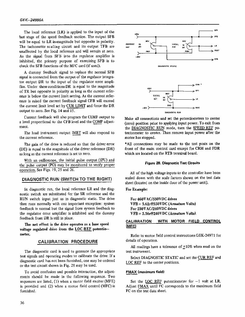
Make all connections and set the potentiometers to center (zero) position prior to applying input power. To exit from the DIAGNOSTIC RUN mode, turn the SPEED REF po- tentiometer to center. Then remove input power after the motor has stopped.
The gain of the drive is reduced so that the driver error *All connections inay be made to the test posts on the (DE) is equal to the magnitude of the driver reference (DR) front of the main control card excep’t for CRM and FDR as long as the current reference is set to zero. which are located on the RTB terminal board.
With an osilloscope, the initial pulse output (IPU) and the pulse output (PO) may be monitored to verify proper operation. See Figs. 19,25 and 26.
DIAGNOSTIC RUN (SWITCH TO THE RSGHT)
In diagnostic run, the local reference LR and the diag nostic switch are substituted for the SR reference and the RUN switch input just as in diagnostic static. The drive then runs normally with one important exception: system feedback is normal but the signal from system feedback to the regulator error amplifier is inhibited and the dummy feedback from DR is still in place.
The net effect is the drive operates as a base speed voltage regulated drive from the LOC REF potentio- meter.
CALlBRATlON PROCEDURE
The diagnostic card is used to generate the appropriate test signals and operating modes to calibrate the drive. If a diagnostic card has not been furnished, one may be ordered or the test circuit shown in Fig. 28 may be used.
To avoid confusion and possible interaction, the adjust- ments should be made in the following sequence. Two sequences are listed, (1) when a motor field exciter (MFE) is provided and (2) when a motor field control (MFC) is furnished.
Figure 28. Diagnostic Test Circuits
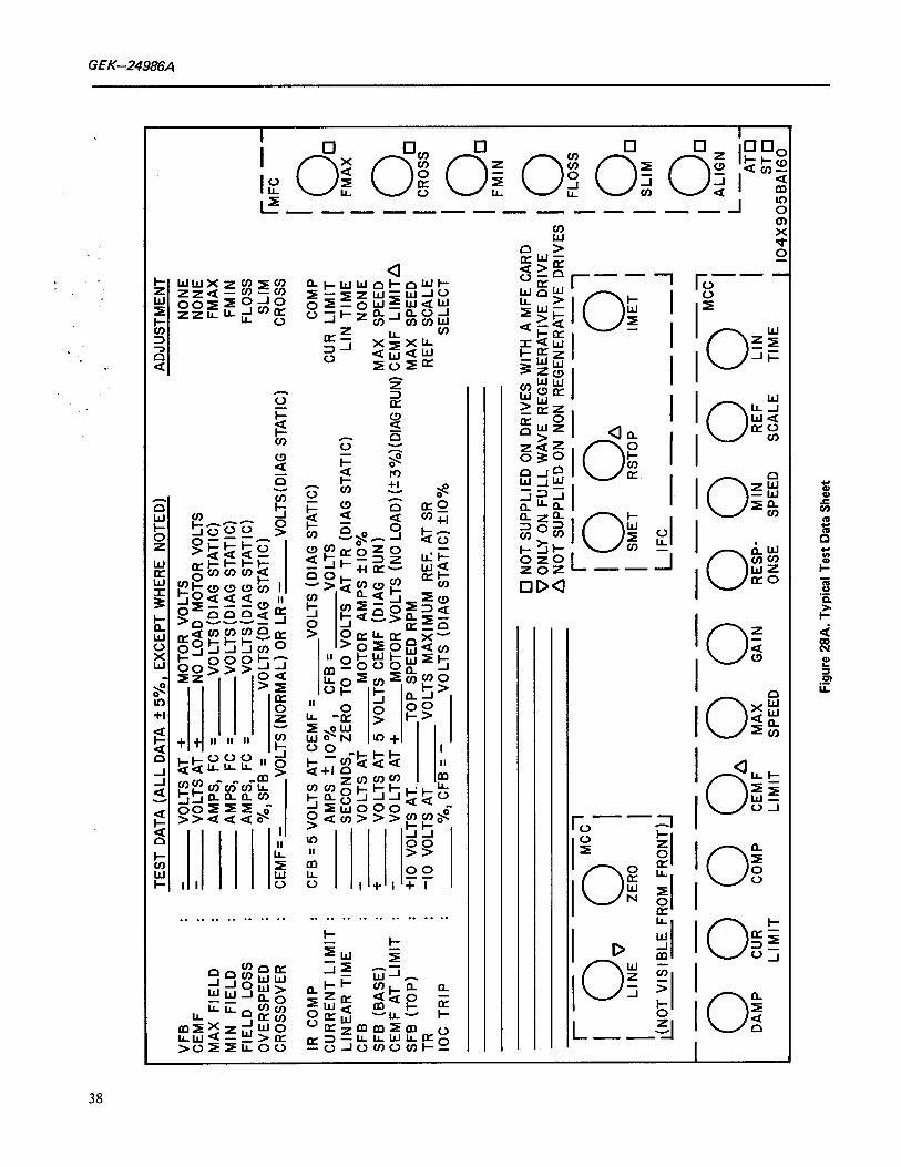
All of the high voltage inputs to the controller have been. scaled down with the scale factors shown on the test data sheet (located on the inside door of the power unit).
For Example:
For 460VACj550VDC drives VFB = 5.62r@550VDC (Armature Volts) For 230VACf240VDC drives VFB = 5.561@240VDC f&mature Volts1
CALlBRATlOW WITH MOTOR FIELD CONTROL (MFC)
Refer to motor field control instructions GEK-2497 1 for details of operation.
All readings have a tolerance of 2 10% when read on the test instrument.
Select DIAGNOSTIC STATIC and set the CUR REF and LOC REF to the center positions.
FMAX (maximum field)
Set the LOC REF potentiometer for -1 volt at LR. Adjust FMAX until FC corresponds to the maximum field FC on the test data sheet.
36

GEL-24986A
TABLE II
Recalibrating Adjustment Sequences
DIAGNOSTIC STATIC MODE, ADJUST
DIAGNOSTIC RUN MODE, ADJUST
NORMAL MODE, ADJUST
WITH MOTOR FIELD
CONTROL
FMAX FMIN * FLOSS SLIM CROSS” LIN TIME CoMp CUR LIMIT I= (IF
USED)
MAX SPEED ALIGN
SMET (IF USED)
REF SCALE
WW MIN SPEED
(IF USED) GAIN RESPONSE
WITH MOTOR FIELD
EXCITER
FLOSS
LIN TIME cm CUR LIMIT I= (IF
USED)
MAX SPEED
Sm (IF USED)
REF SCALE MAX SPEED
(TRW MIN SPEED (IF USED)
GAIN RESPONSE DAMP
*Some drives may be provided with a motor field control card (MFC) and not have any constant HP range. On such drives set CROSS full CW and FMIN per Test Data Sheet or at 80% of rated field current.
Drives with a motor field exciter (MFE) do not have CROSS, FMIN, SLIM and ALIGN adjustments. ---
NOTE: A MOTOR FIELD CONTROL CARD (MFC) MAY BE FURNISHED ON BASE SPEED DRIVES (CONSTANT m) TO PROVIDE FIELD ECONOMY, TACHOMETER MONITOR OR FIELD CURRENT REGULATION FUNC- TIONS.
37
VF
CE MP
MI
Fit
ov
CR
IR
cu
LII
CF
SF
CE
SF
TA
IO’
- - - - - - r
I I 1
. ”
. :
.
TEST
D
ATA
(ALL
D
ATA
+ 5%
, EX
CEP
T W
HER
E N
OTE
D)
ADJU
STM
ENT
!F
: -
VOLT
S AT
+
MO
TOR
VO
LTS
NO
NE
VOLT
S AT
+
NO
LO
AD
MO
TOR
VO
LTS
NO
NE
rX
FIEL
D
: AM
PS,
FC
= VO
LTS
(DIA
G
STAT
IC)
FMAX
N
FI
ELD
AM
PS,
FC
= VO
LTS
(DIA
G
STAT
IC)
FMIN
:L
D
LOSS
:
AMPS
, FC
=
VOLT
S(D
IAG
ST
ATIC
) FL
OSS
‘E
RSP
EED
%
, SF
B =
VOLT
S (D
IAG
ST
ATIC
) SL
IM
OSS
OVE
R
CEM
F=
- VO
LTS
(NO
RM
AL)
OR
LR
= -
VOLT
S(D
IAG
ST
ATIC
) C
RO
SS
r ME-
CO
MP
CFB
= 5
VO
LTS
AT C
EMF
= VO
LTS
(DIA
G
STAT
IC)
CO
MP
RR
ENT
LIM
IT
: AM
PS
+ 10
%
NEA
R
TIM
E :
SEC
ON
DS,
ZE
RO
:K
VO
LTS
n”To
’;‘R
s (D
IAG
ST
ATIC
) C
UR
LI
MIT
LI
N
TIM
E :
- B
” (B
AS
E)
. +
VOLT
S AT
M
OTO
R
AMPS
21
0%
NO
NE
:MF
AT
LIM
IT
I -
VOLT
S AT
5
VOLT
S C
EMF
(DIA
G
RU
N)
MAX
SP
EED
VO
LTS
AT +
M
OTO
R
VOLT
S (N
O L
OAD
)(!:3
%)(D
IAG
R
UN
) C
EMF
LIM
ITa
B (
TOP)
:
+I0
VOLT
S AT
, TO
P SP
EED
R
PM
MAX
SP
EED
, C
TR
IP
I -1
0 VO
LTS
AT
VOLT
S M
AXIM
UM
R
EF.
AT S
R
REF
SC
ALE
O/o
, CFB
= -
VO
LTS
(DIA
G
STAT
IC)
woo
/c,
SELE
CT
I I 0
t
I
FMIN
0 N
OT
SUPP
LIED
O
N D
RIV
ES
WIT
H
A M
FE
CAR
D
VON
LY
ON
FU
LL
WA
VE
R
EGEN
ERAT
IVE
DR
IVE
n N
OT
SUPP
LIED
O
N
NO
N R
EGEN
ERAT
IVE
DR
IVES
IO
--
---
----
---
LIM
IT
LIM
IT
SPEE
D Fi
gure
28
A.
Typi
cal
Test
Da
ta S
heet
GE K-24986A
FMIN (minimum field - limit)
Set LOC REF potentiometer for -6 volts at LR. Adjust FMIN until FC corresponds to minimum field FC on the test data sheet.
COMP (compensation - IR)
Set the LOC REF potentiometer to center positron. Adjust the CUR REF potentrometer Fwd until CFB is at -5 volts &IO%).
Monitor CEMF and adjust CoMp until CEMF equals the value on the test data sheet.
On a speed regulated drive, COMP may be retrrmmed for stabilizmg the drive when operating above base speed.
On a voltage (CEMF) regulated drive, COMP should be set for zero speed regulation at a specific speed (typically 50%) when the load changes from minimum to maximum? If the speed decreases with increasing load the Cm potentiometer should be turned further clockwise. Always recheck the MAX SPEED adjustment after making a COMP adjustment.
CUR LIMIT (current limit)
Set LOC REF for 10 volts at DR. Set CUR LiMIT full CW. Adjust the CUR REF potentiometer until CFB corresponds to the current limit level on the test data sheet. Monitor DR and turn CUR LIMIT CCW un- tii DR starts to decrease.
~ (load instrument calibration)
Adjust the CUR REF until CFB corresponds to full load current. Verify the optional load instrument reads full load. If not, remove power; adjust IMET and repeat.
FLOSS (field loss - fault)
Set the LOC REF to center position and reset the drive. Adjust FLOSS full CCW.
Monitor FC and move the LOC REF potentiometer Rev until FC corresponds to the field loss value on the test data sheet. Slowly rotate FLOSS CW until the “Ready to Run” light turns off indicating a drrve fault. Normally set at 75% of the FMIN setting.
SLIM (Speed limit - overspeed fault)
Set the LOC REF to center position and reset the drive. Adjust SLIM full CW.
Momtor SFB and move the LOC REF potentiometer Fwd until SFB corresponds to the overspeed limit on the
test data sheet: Slowly adjust SLIM CCW until the “Ready to Run” light turns off indicating a drive fault. Normally set with 11.5 volts (115%) at SFB.
CROSS (cross over - field)
Set CROSS full CCW. Turn the LOC REF potentiometer Fwd until LR corresponds to the cross over LR on the test data sheet.
Monitor FC and adjust CROSS CW until FC just starts to increase. CROSS may be checked when the drive is running m normal operation by verifying that CEMF reads the value on the test data sheet with the drive operatmg above base speed.
LIN TIME (linear time)
Monitor TR and set -10 volts with the LOC REF po- tentiometer. Flip the diagnostic switch to NORMAL, then back to STATIC and measure the time for TR to ramp from 0 to -10 volts. Adjust LIN TIME as required.
Set the LOC REF to the center position; reset the drive and switch to DIAGNOSTIC RUN to operate the drive as a voltage regulator.
MAX SPEED/ALIGN (max speed/tachometer loss align)
Turn MAX SPEED full CCW. Turn AL&b! full CW. Adjust the LOC REF potentiometer until CEMF reads -5 volts (*lo%). Adjust MAX SPEED until SFB corresponds to the base speed feedback on the test data sheet.
Monitor TA and adjust ALIGN CCW until TA is approx- imately zero volts.
SMET (speed instrument calibration)
Turn the LOC REF potentiometer until SFB is 3 volts, (-110%). The optional speed indicator should indicate 30% top speed. If it does not, switch to NORMAL to initiate a shut down. Remove power, adjust SMET and repeat.
RETURN THE DIAGNOSTIC SWITCH TO NORMAL
REF SCALE/MAX SPEED (reference scale/max speed)
Turn the REF SCALE full CCW. Start the drive and apply top speed reference to SR. Adjust the REF SCALE potentiometer until SFB is 10 volts (+lO%). This normal- izes the timed reference TR and speed feedback, SFB for 10 volts (flO%), at top speed.
Now measure motor RPM and adjust MAX SPEED (if necessary) until the actual RPM corresponds to the desired top speed. If actual top RPM was off by more than 5% reset ALIGN as detailed above.
39
GEK-24986A
MIN SPEED (minimum speed)
Reduce the system reference to zero and start the drive. Adjust MIN SPEED, as required, to meet system mimimum speed requirements.
GAIN, RESPONSE, DAMP (stability adjustments)
The GAIN adjustments affects the stability over the entire speed range. This potentiometer will normally be set between 9 and 12 o’clock.
The RESPONSE adjustment affects stability in the con- stant torque region (below base speed). Adjustments should not be made when operating above base speed. The poten- tiometer will normally be set between 10 and 1 o’clock.
The DAMP adjustment primarily affects the region around cross over between the constant torque and cons- tant horsepower regions. Normally damping is not required and the potentiometer is set fully counter clockwise (7 o’clock).
CALIBRATION WITH MOTOR FIELD EXCITER (MFE)
Refer to motor field exciter instructions GEK-24972 for details of operation.
SELECT DIAGNOSTIC STATIC and set CUR REF and LOC REF to the center positions.
FLOSS (field loss - fault)
Adjust FLOSS full CCW and reset the drive.
Monitor FC and move the LOC REF Rev until FC corresponds to the field loss value on the test data sheet. Slowly adjust FLOSS CW until the “Ready to Run” light turns off indicating a drive fault. Normally set at 50% of rated motor field current.
COMP (compensation - IR)
Adjust the LOC REF potentiometer to the center position. Adjust the CUR REF potentiometer Fwd until CFB is at -5 volts (310%).
Monitor CEMF and adjust CoMp until CEMF equals the value on the test data sheet.
On a voltage (CEMF) regulated drive, COMP should be set for zero speed regulation at a specificspeed (typically 50%) when the load changes from minimum to maximum. If the speed decreases with increasing load the COMP adjustment should be turned further clockwise. Always re- check the MAX SPEED potentiometer after makmg a COMP adjustment.
CUR LIMIT (current limit)
Set the LOC REF for 10 volts at DR. Adjust CQJJ LIMIT full CW. Turn the CUR REF potentiometer until CFB corresponds to the current limit value on the test data sheet.
Monitor DR and turn CUR LIMIT CCW until DR starts to decrease.
m (load instrument calibration)
Turn the CUR REF potentiometer until CFB corre- sponds to full load current. Verify the optional load instru- ment reads full load. If not, remove power, adJust IMET and repeat.
LIN TIME(linBar time)
Monitor TR and set to -10 volts with the LOC REF potentiometer. Flip the diagnostic switch to NORMAL then back to STATIC and measure the time for TR to ramp from 0 to -10 volts. Adjust LIN TIME according to the test data sheet or as required.
Set the LOC REF to the center position and switch to DIAGNOSTIC RUN.
MAX SPEED (maximum speed)
Adjust the LOC REF until the motor is running at actual top speed. Adjust MAX SPEED until SFB is 10 volts klO%).
SMET (speed instrument calibration)
Turn the LOC REF potentiometer until SFB is 3 volts (210%) the optional speed mdicator should indicate 30% top speed. If it does not, switch to NORMAL to initiate a shut down. Remove power, adjust SMET and repeat.
Return the DIAGNOSTIC SWITCH TO NORMAL.
REF SCALE (reference scale)
Turn the REF SCALE potentiometer full CCW. Start the drive and apply top speed reference to SR. Adjust the REF SCALE potentiometer until SFB is 10 volts (tiO%). This normalizes the timed reference TR and speed feedback SFB for 10 volts @lo%) at top speed.
MIN SPEED (minimum speed)
Reduce the system reference to zero and start the drive. Adjust MIN SPEED as required to meet system minimum speed requirements.

. GEK-24986A
GAIN, RESPONSE, DAMP (stability adjustments)
The GAIN potentiometer is normally set fully counter clockwise (7 o’clock).
The RESPONSE potentiometer is adjusted for stable operation normally in the range of 10 to 1 o’clock.
Normally damping is not required and therefore DAMP should be set fully counter clockwise (7 o’clock).
MODIFICATIONS AND OPTIONS
The modification module, MDM, mounted on top of the basic power unit is required for any of the following modi- fications.
Dynamic braking Reversing with dynamic braking AC line circuit breaker Blower motor control
Other modifications and/or options are available as Kits which may either be factory assembled and wired or in- stalled in the main controller by the user. The modification Kits are provided with mounting hardware and cut to length wire harness with marked terminals when required, for easy installation. The power unit modification Kits are:
Diagnostic panel Test instrument and probe Process Control follower (with independent jog refer-
ence) Jog by pushbutton (with independent jog reference) Timed overcurrent protection
Modifications and/or options that affect devices and wir- ing external to the power unit include:
Auto/Manual operation Remote current limit Speed indicator Load indicator Tachometer (for improved speed regulation)
DYNAMIC BRAKING
The dynamic braking resistor(s) are mounted on the back panel in the MDM, (modification module) and selected to produce a dynamic braking current of 125 to 150% of rated armature current at rated armature voltage.
The dynamic braking resistor(s) will be connected across the motor armature by closing in the DB con- tactor which, depending on horsepower, may have one, two, or three contactor poles.
(RAII (RA2)
PS MAX J
PS 115 2 --r--ij,p ------- --E(i;,A
(2) ----
VAC +-- _
I I
FIG.29 DYNAMIC BRAKING RESISTOR CONNECTIONS
41
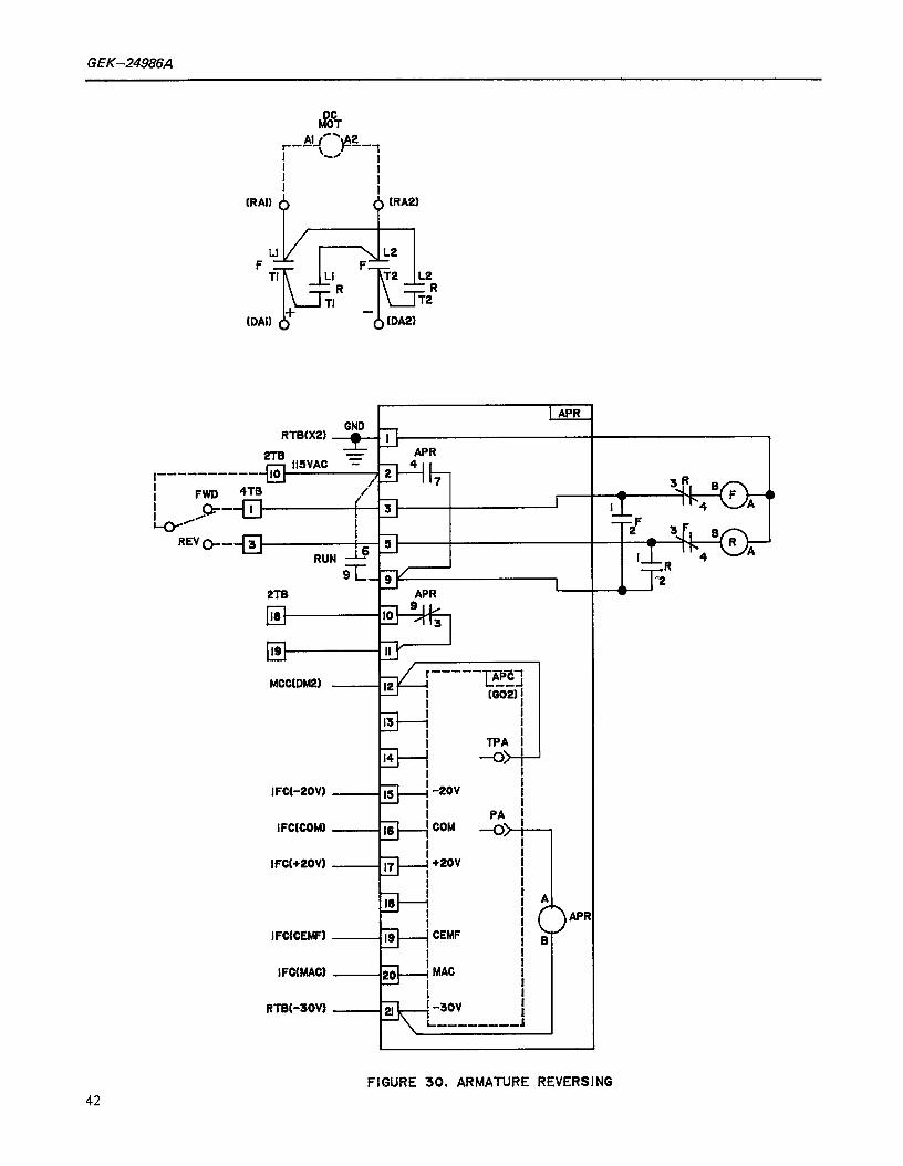
G EK-24986A~
F Lti TI I LI
L
R TI I
(0
r APR
MCC(DM2) 13 i
I
-E I4 I
I 15
I
I
I FCt-POW
IFCtCOhU
IFC[+2OV)
i b II I
I FCEEMF)
IFCMAC)
ATB(-30V)
CEMF
MAC !
:
I
-------- :
AP R
FIGURE 30. ARMATURE REVERSING 42
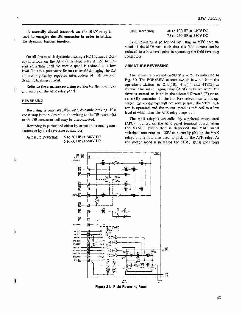
. GEK-24986A
A normally closed interlock on the MAX relay is
I used to energize the DB contactor in order to initiate the dynamic braking function.
On all drives with dynamic braking a NC (normally clos- ed) interlock on the APR (anti plug) relay is used to pre- vent restarting until the motor speed is reduced to a low level. This 1s a protective feature to avoid damaging the DB contactor poles by repeated interruption of high levels of dynamic braking current.
1 Refer to the armature reversing section for the operation
and wiring of the APR relay panel.
REVERSING
Reversing is only available with dynamic brakmg. If a coast stop is more desirable, the wiring to the DB resistor(s) or the DB contactor coil may be disconnected.
Reversing is performed either by armature reversing con- tactors ox by field reversing contactors:
Armature Reversing 5 to 30 HP at 240V DC 5 to 60 HP at 55OV DC
Field Reversing 40 to 100 HP at 240V DC 75 to 250 HE’ at 550V DC
Field reversing is performed by using an MFC card in- stead of the MFE card such that the field current can be reduced to a low level prior to operating the field reversing contactors.
ARMATURE REVERSING
The armature reversing circuitry is wired as indicated in Fig. 30. The FOR/REV selector switch is wired from the operator’s station to 2TB(lO), 4TB( 1) and 4TB(3) as shown. The anti-plugging relay (APR) picks up when the drive is started to latch in the selected forward (F) or re- verse (R) contactor. If the For-Rev selector switch is op- erated the contactors will not reverse until the STOP but- ton is operated and the motor speed is reduced to a low level at which time the APR relay drops out.
The APR relay is controlled by a printed circuit card (APC) mounted on the APR panel terminal board. When the START pushbutton 1s depressed the MAC signal switches from zero to -20V to normally pick up the MAX relay, but is now also used to pick up the APR relay. As the motor speed is increased the CEMF signal goes from
,UDH ,RFl,
Figure 31. Field Reversing Panel
43
GEK-24986&
zero to approximately -5 volts at rated armature voltage to latch in APR relay. With MAC returned to zero (STOP) APR will drop out as the CEMF voltage is reduced to a level corresponding to approximately 10% of rated arma- ture voltage. The drop out level is adjustable by the @ potentiometer on the APC card from 8% to 40%. Normally the APR potentiometer should be set fully CCW for an 8% drop= level.
NOTE
DO NOT SET THE APR POTENTIOMETER PAST MID-POSITION. -
FIELD REVERSING
The field reversing circuitry is shown in Fig. 3 1 and Fig. 32. The FOR/REV selector switch is wired from the operators station to 2TB(lO) and 4TB( 1) through 4TB(5) as illustrated.
Field excitation is applied when START (or JOG) is initiated. At this time the APR relay picks up, making the selected forward, FC, or reverse, RC, contactor pick up. At the same time the VR relay drops out to disconnect the RF point from t20 volts, which makes the field current go to the level set by the FMAX notentiometer on the MFC card. As field current is a-, the FR relay drops out to latch in the selected contactor.
If the STOP button is depressed, the motor will stop by dynamic braking. The APR relay drops out at a low motor speed as the CEMF signal drops below a preset level.
NOTE:
REFER TO THE ARMATURE REVERSING SEC- TION FOR A DESCRIPTION OF THE APR RELAY OPERATION.
At this time the MFC card is programmed into its FIELD ECONOMY mode; i.e. the field current is reduced to about 70% of normal while the motor is at standstill,
Now if the FOR/REV selector switch is operated, the VR relay picks up; t2OV is applied to RF and the field is programmed off. The voltage at SFC is proportional to field current and when a low level is reached the FR relay picks up and the field contactor drops out.
As the contacts open the stored energy in the field inductance causes arcing between the contact tips for a few milliseconds until a pre-charged capacitor C 1, is applied across the output terminals. The capacitor will shunt the current away from the contact tips to extinguish the arcing
44
almost instantly. The field current will quickly reverse the capacitor charge, but the voltage will be clipped by the metal oxide varistor MOV, which now quickly dissipates the remaining inductive field energy.
The level at which the FR relay picks up to initiate switching is adjustable by the FR potentiometer on the FRC card. Generally the potentiometer is turned fully CCW for a minimum switching level.
The circuitry is arranged to permit a direct speed reversal without a distinct stop. With the motor running at preset speed, operate the FOR/REV selector switch. Then mom- entarily depress the STOP pushbutton to initiate dynamic braking and immediately push and hold the START but- ton until motor accelerates in the opposite direction. In this operating mode the reversing time may be reduced by increasing the level at which the APR and FR relays ope- rate. By turning the APR potentiometer CW the APR relay will drop out at a higher speed to initiate field turn off earlier in the dynamic braking (DB) cycle. By turning the FR potentiometer CW the contactor switching will be initiated at a higher level of field current. As the field is reversed while the motor is still rotating the motor terminal voltage (CEMF) reverses and when the MA contactor picks up and output power is reapplied the motor will regenerate to zero speed and continue accelerating to the preset speed in the opposite direction. If any appreciable arcing occurs during the switching of the field contactor, the FR poten- - tiometers must be turned CCW.
NOTE
IF THE START PUSHBUTTON IS NOT OPERATED IN THE ABOVE SEQUENCE THE STOPPING TIME WILL INCREASE SINCE DYNAMIC BRAKING TORQUE IS LOST AS THE FIELD CURRENT IS PROGRAMMED TO ZERO.
Fig. 31 shows a wire connection from FRC (TPA) to FRP(8) to MCC (DM2). Normally a jumper on the main control card (MCC) connects MCC (FEA) to MCC (DM2) in order to delay FIELD ECONOMY until dynamic braking is completed. By removing the (FEA)-(DM2) jumper the dynamic braking torque will be reduced to produce a “softer” deceleration.
AC LINE”CIRCUIT BREAKER/SWITCH
The molded case switch (or circuit breaker) provides a manual AC line disconnect with provision for pad- locking of the external operating handle.
For 40HP and less at 23OY and 1OOHP and less at 46OV, a circuit breaker with a magnetic trip mechanism is provided. For higher horsepower ratings a molded case switch without any trip mechanism is used.
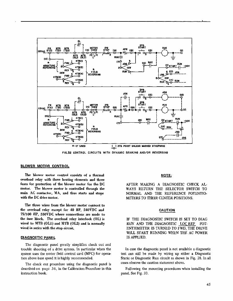
3PB
*-IF USED I I 2TB POINT UNLESS MARKED OTHERWISE
FIG.32 CONTROL CIRCUITS WITH DYNAMIC BRAKING AND/OR REVERSING
BLOWER MOTOR CONTROL
The blower motor control consists of a thermal overload relay with three heating elements and three fuses for protection of the blower motor for the DC motor. The blower motor is controlled through the main AC contactor, MA, and thus starts and stops with the DC drive motor.
The three wires from the blower motor connect to the overload relay except for 40 HP, 240VDC and ‘75/100 HP, 550VDC where connections are made to the fuse block. The overload relay interlock (OL) is wired to MTB (OLl) and MTB (OL2) and is normally wired in series with the stop circuit.
DIAGNOSTIC PANEL
The diagnostic panel greatly simplifies check out and trouble shooting of a drive system. In particular when the system uses the motor field control card (MFC) for opera- tion above base speed it is highly recommended.
The check out procedure using the diagnostic panel is described on page 36, in the Calibration Procedure in this instruction book.
NOTE. L
AFTER MAKING A DIAGNOSTIC CHECK AL WAYS RETURN THE SELECTOR SWITCH TO NORMAL AND THE REFERENCE POTENTIO- METERS TO THEIR CENTER POSITIONS.
CAUTION
IF THE DIAGNOSTIC SWITCH IS SET TO DIAG RUN AND THE DIAGNOSTIC LOC REF POT- ENTIOMETER IS TURNED TO FWD, THE DRIVE WILL START RUNNING WHEN THE AC POWER IS APPLIED.
In case the diagnostic panel is not available a diagnostic test can still be made by wiring up either a Diagnostic Static or Diagnostic Run circuit as shown in Fig. 28. In all cases observe the caution statement above.
Following the mounting procedures when installing the panel. See Fig. 33.
45

RETAINING CUP
l/4 TURN
MO”NTlNG SCREW
MGUNTlNG BRACKET
W\DGGR FRONT MOUNTING INSTRUCTIONS
SCREW
1. Remove the retaining clip from the diagnostic panel and attach it over the hole in the offset door flange.
2. Mount the panel loosely to the mounting bracket using the two flat washers and self tapping screws.
3. Align the panel and fasten the l/4 turn screw to the retaining clip.
4. Tighten the mounting screws.
5. Pass the diagnostic harness underneath the main control card (MCC) bracket and connect the labeled wires to the corresponding MCC terminal board points DPl, DP2, MAC, LR and the RTB terminal board points RSET, COM, +2OV, -2OV, FDR, CRM and CFB.
Figure 33. Diagnostic Panel
TEST INSTRUMENT
The instrument with its probe is used to measure any of the DC signals on the test row along the front (bottom) of the main control card (MCC). Used with the diagnostic panel, the instrument provides a convenient way of recali- bration or verification of most of the preset adjustments.
The test probe has two connection points for a full scale reading of either 4 volts or 20 volts.
Mount the instrument by first removing the two mount- ing screws and placing it through the slot in the left hand side of the door front. Place the instrument against the bot- tom side of the main control card (MCC) bracket and line the mounting holes up with the two holes in the bracket. Insert the screws from the top of the bracket and tighten. Then connect the common lead attached to the negative instrument terminal to the main control card terminal board marked COM.
PROCESS CONTROL FOLLOWER
The process control follower assembly is located in the main control module to the right of the RUN relay and above 2TB. It consists of a terminal board mounted print- ed circuit card on a bracket which mounts to the two studs located in the relay bracket.
Set up procedure: Wire the process controller, the manual speed potentiometer and the MAN/AUTO selector switch as shown in Fig. 34.
1.
2.
3.
4.
SR
4
c 2TB
Dashed lines indicate factory made connections if the Kit is ordered factory mounted.
Remove jumpers (SRH)-(COM) and (JH)-(COM) on the main control card (MCC)
For jogging at MIN SPEED remove wire PCF (JOGR)- 2TB(25).
For independent jog reference remove jumper 2TB(25)- 2TB(26).
Due to the low current level it is recommended to paral- 1eI the two Form C contacts of the AUTO/MAN selector switch, by connecting points 1 and 4, 2 and 5 and 3 and 6.
Figure 34. Process Control Follower
1. In the MAN mode with the speed potentiometer fully CW sets the REF SCALE potentiometer for -lOV at test post TR. Set the MAX SPEED potentiometer. (Refer to the start up section of this Instruction book).
2. In AUTO mode with minimum controller output, set the MIN process control follower (PCF) potentio- meterr zero (or minimum) speed.
46
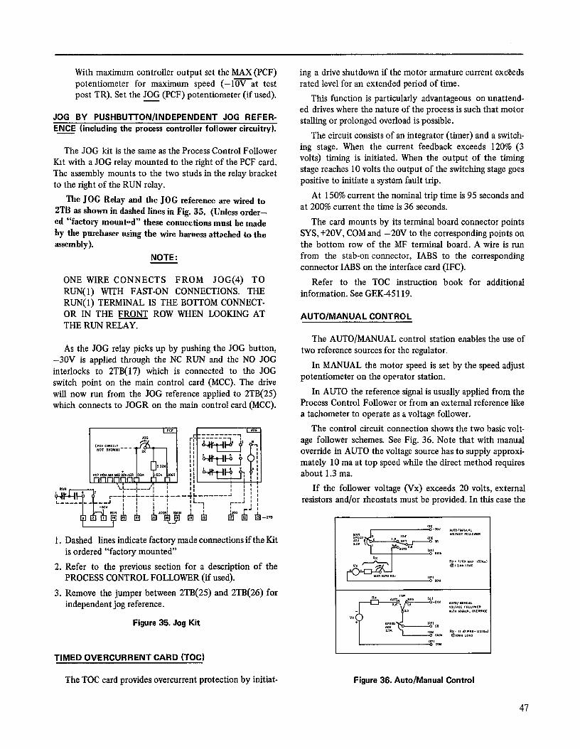
With maximum controller output set the MAX (PCF) potentiometer for maximum speed (-Irat test post TR). Set the JOG (PCF) potentiometer (if used).
JOG BY PUSHBUTTON/INDEPENDENT JOG REFER- ENCE (including the process controller follower circuitry).
The JOG kit is the same as the Process Control Follower tit with a JOG relay mounted to the right of the PCF card. The assembly mounts to the two studs in the relay bracket to the right of the RUN relay.
The JOG Relay and the JOG reference are wired to 2TB as shown in dashed lines in Fig. 35. (Unless order- ed “factory moun+d” these connections must he made by the purchaser using the wire harness attached to the assembly).
NOTE:
ONE WIRE CONNECTS FROM JOG(4) TO RUN(l) WITH FAST-ON CONNECTIONS. THE RUN(l) TERMINAL IS THE BOTTOM CONNECT- OR IN THE FRONT ROW WHEN LOOKING AT THE RUN RELAY.
As the JOG relay picks up by pushing the JOG button, -30V is applied through the NC RUN and the NO JOG interlocks to 2TB(17) which is connected to the JOG switch point on the main control card (MCC). The drive will now run from the JOG reference applied to 2TB(25) which connects to JOGR on the main control card (MCC).
1. Dashed 1. Dashed lines indicate factory made connections if the Kit lines indicate factory made connections if the Kit is ordered “factory mounted” is ordered “factory mounted”
2. Refer to the previous section for a description of the 2. Refer to the previous section for a description of the PROCESS CONTROL FOLLOWER (if used). PROCESS CONTROL FOLLOWER (if used).
3. Remove the jumper between 2TB(25) and 2TB(26) for 3. Remove the jumper between 2TB(25) and 2TB(26) for independent jog reference. independent jog reference.
Figure 35. Jog Kit Figure 35. Jog Kit
ing a drive shutdown if the motor armature current ex&eds rated level for an extended period of time.
This function is particularly advantageous on unattend- ed drives where the nature of the process is such that motor stalling or prolonged overload is possible.
The circuit consists of an integrator (timer) and a switch- ing stage. When the current feedback exceeds 120% (3 volts) timing is initiated. When the output of the timing stage reaches 10 volts the output of the switching stage goes positive to initiate a system fault trip.
At 150% current the nominal trip time is 95 seconds and at 200% current the time is 36 seconds.
The card mounts by its terminal board connector points SYS, +2OV, COM and -20V to the corresponding points on the bottom row of the MF terminal board. A wire is run from the stab-on connector, IABS to the corresponding connector IABS on the interface card (IFC).
Refer to the TOC instruction book for additional information. See GEK-45 119.
AUTO/MANUAL CONTROL
The AUTO/MANUAL control station enables the use of two reference sources for the regulator.
In MANUAL the motor speed is set by the speed adjust potentiometer on the operator station.
In AUTO the reference signal is usually applied from the Process Control Follower or from an external reference like a tachometer to operate as a voltage follower.
The control circuit connection shows the two basic volt- age follower schemes. See Fig. 36. Note that with manual override in AUTO the voltage source has to supply approxi- mately 10 ma at top speed while the direct method requires about 1.3 ma.
If the follower voltage (Vx) exceeds 20 volts, external resistors and/or rheostats must be provided. In this case the
I
TIMED OVERCURRENT CARD (TOC)
The TOC card provides overcurrent protection by initiat- Figure 36. Auto/Manual Control
47
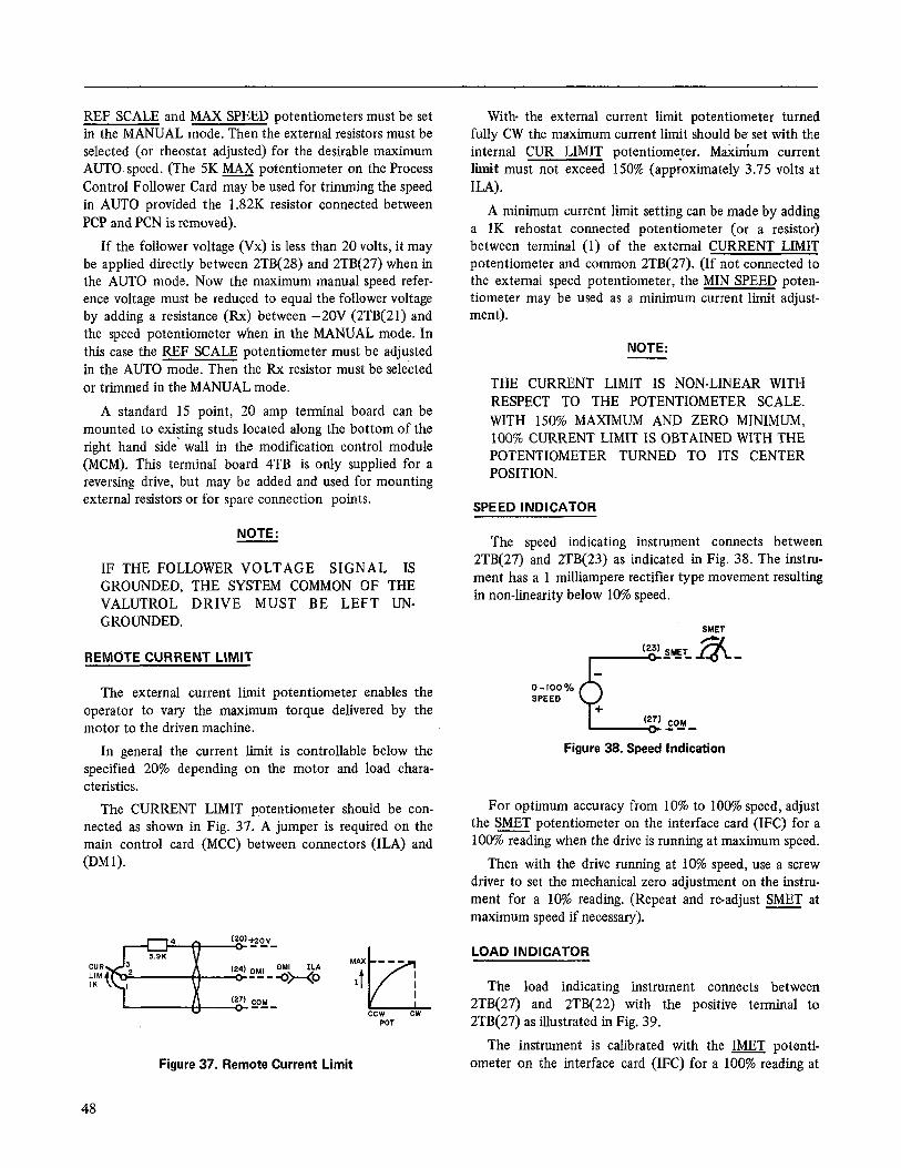
REF SCALE and MAX SPEED potentiometers must be set in the MANUAL mode. Then the external resistors must be selected (or rheostat adjusted) for the desirable maximum AUTO. speed. (The 5K MAX potentiometer on the Process Control Follower Card maybe used for trimming the speed in AUTO provided the 1.82K resistor connected between PCP and PCN is removed).
If the follower voltage (Vx) is less than 20 volts, it may be applied directly between 2TB(28) and 2TB(27) when in the AUTO mode. Now the maximum manual speed refer- ence voltage must be reduced to equal the follower voltage by adding a resistance (Rx) between -20V (2TB(21) and the speed potentiometer when in the MANUAL mode. In this case the REF SCALE potentiometer must be adjusted in the AUTO mode. Then the Rx resistor must be selected or trimmed in the MANUAL mode.
A standard 15 point, 20 amp terminal board can be mounted to existing studs located along the bottom of the right hand side‘ wall in the modification control module (MCM). This terminal board 4TB is only supplied for a reversing drive, but may be added and used for mounting external resistors or for spare connection points.
NOTE:
IF THE FOLLOWER VOLTAGE SIGNAL IS GROUNDED, THE SYSTEM COMMON QF THE VALUTROL DRIVE MUST BE LEFT UN- GROUNDED.
REMdTE CURRENT LIMIT
The external current limit potentiometer enables the operator to vary the maximum torque delivered by the motor to the driven machine.
In general the current limit is controllable below the specified 20% depending on the motor and load chara- cteristics.
The CURRENT LIMIT potentiometer should be con- nected as shown in Fig. 37. A jumper is required on the main control card (MCC) between connectors (ILA) and (DM 1).
Figure 37. Remote Current Limit
With- the external current limit potentiometer turned fully CW the maximum current limit should be set with the internal CUR LIMIT potentiometer. M&i&m current hit must not exceed 150% (approximately 3.75 volts at ILA).
A minimum current limit setting can be made by adding a 1K rehostat connected potentiometer (or a resistor) between terminal (1) of the external CURRENT LIMIT potentiometer and common 2TB(27). (If not connected to the external speed potentiometer, the MIN SPEED poten- tiometer may be used as a minimum current limit adjust- ment).
NOTE:
THE CURRENT LIMIT IS NON-LINEAR WITH RESPECT TO THE POTENTIOMETER SCALE. WITH 150% MAXIMUM AND ZERO MINIMUM, 100% CURRENT LIMIT IS OBTAINED WITH THE POTENTIOMETER TURNED TO ITS CENTER POSITION.
SPEED INDICATOR
The speed indicating instrument connects between 2TB(27) and 2TB(23) as indicated in Fig. 38. The instru- ment has a 1 milliampere rectifier type movement resulting in non-linearity below 10% speed.
SMET
o-lOO% SPEED
P
+ cm COM B-s
Figure 38. Speed Indication
For optimum accuracy from 10% to 100% speed, adjust the SMET potentiometer on the interface card (IFC) for a 100% reading when the drive is running at maximum speed.
Then with the drive running at 10% speed, use a screw driver to set the mechanical zero adjustment on the instru- ment for a 10% reading. (Repeat and re-adjust SMET at maximum speed if necessary).
LOAD INDICATOR
The load indicating instrument connects between 2TB(27) and 2TB(22) with the positive terminal to 2TB(27) as illustrated in Fig. 39.
The instrument is calibrated with the IMET potenti- ometer on the interface card (IFC) for a 100% reading at
48
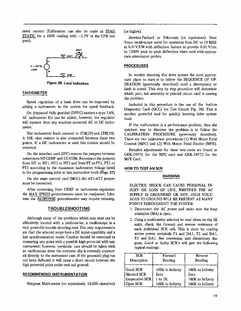
rated current (Calibration can also be made in DIAG. STATIC for a 100% reading with -2SV at the CFB test post).
IMET
O-150% LOAD
9.
+ (27) COH m-B
Figure 39. Load Indication
TACHOMETER
Speed regulation of a basic drive can be improved by adding a tachometer to the system for speed feedback.
On dripproof fully guarded (DPFG) motors a type 5AN, AC tachometer Kit can be added; however, the regulator will operate from any machine mounted AC or DC tacho- meter.
The tachometer leads connect to 2TB(29) and 2TB(30). A 56K ohm resistor is also connected between these two points. If a DC tachometer is used this resistor should be removed.
On the interface card (IFC) remove the jumpers between connectors NT-CEMF and CC-COM. Reconnect the jumpers from NT to NTl, NT2 or NT3 and from PT to PTl, PT2 or PT3 according to the maximum tachometer voltage listed in the programming table in this instruction book.(Page 57)
On the main control card (MCC) the ATl-AT2 jumper must be connected.
After converting from CEMF to tachometer regulation the MAX SPEED potentiometer must be readjusted. Like- wise the RESPONSE potentiometer may require retuning.
TROUBLESHOOTING
ELECTRIC SHOCK CAN CAUSE PERSONAL IN- JURY OR LOSS OF LIFE. WHETHER THE AC SUPPLY IS GROUNDED OR NOT, HIGH VOLT- AGES TO GROUND WILL BE PRESENT AT MANY POINTS THROUGHOUT THE SYSTEM. 1. Disconnect the AC power and make sure the loop
contactor (MA) is open. Although many of the problems which may arise can be
effectively located with a multi-meter, a oscilloscope is a very powerful trouble shooting tool. The only requirements are that the selected scope have a DC input capability and a line synchronization mode. Caution should be exercised in measuring any point with a possible high potential with any instrument; however, particular care should be taken with an oscilloscope since the common clip is normally connect- ed directly to the instrument case. If the grounded plug has not been defeated it will cause a short circuit between the high potential point under test and ground.
2. Using a multi-meter selected to read ohms on the lK scale, check the forward and reverse resistance of each individual SCR cell. This is done by reading across power terminals Tl and DA1 , T2 and DAl, T3 and DAl. See conversion unit elementary dia- gram. Good or faulty SCR’s will give the following typical readings:
c SCR
Description
RECOMMENDED INSTRUMENTATION Good SCR 1OOK to Infinity 1 OOK to Infinity Shorted SCR Zero Zero Inoperative SCR 1 to 2K 100K to Infinity
Simpson Multi-meter (or equivalent). 10,000 ohms/volt Open SCR
(or higher).
HewlettPackard or Tektronix (or equivalent). Dual Trace oscilloscope rated for operation from DC to 10 MHZ at O.OlV/CM with deflection factors to provide 0.01 V/cm to 1300V peak to peak deflection when used with approp riate attentuator probes.
PROCEDURES
In trouble shooting this drive system the most approp- riate place to start is to follow the SEQUENCE OF OP- ERATION (previously described) until a discrepancy or fault is noted. This step by step procedure will determine which part, sub assembly or printed circuit card is causing the problem.
Included in this procedure is the use of the built-in Diagnostic Card (DCC) (or Test Circuit Fig. 28). This is another powerful tool for quickly locating drive system fault.
If the malfunction is a performance problem, then the quickest way to discover the problem is to follow the CALIBRATION PROCEDURE (previously described). There are two calibration procedures (1) With Motor Field Control (MFC) and (2) With Motor Field Exciter (MFE).
Detailed adjustments for these two cards are found in GEK-24971 for the MFC card and GE&24972 for the MFE Card.
HOW TO TEST AN SCR
WARNING
Forward Reading
Reverse Reading
1OOK to Infinity 1 OOK to Infinity
49

3. Since an open SCR will give about the same resis- tance reading as a good SCR another method must be used to find this type of fault. It should be pointed out; however, that practically all cells fail by short- ing and very few by opening. If an open SCR is sus- pected or it is desired to check the switching opera- tion of an SCR, the following circuit should be used:
REMOVAL/REPAIR
CONVERSION MODULE
The conversion module is best removed as follows:
Disconnect the three AC input power and DC output leads as shown.
The multimeter is selected to read ohms on the 1K scale, and is connected to read the forward resistance of the SCR. When switch SW is closed, the forward resistance of a good SCR will change from a high value (100K to infinity) to a low value (1 to 10K). When the switch is opened a good SCR will revert to its high forward resistance or blocking state, if the holding current (multi-meter battery) source is mom- entarily removed. A faulty SCR will not switch re- maining in either an open or a conducting state.
If any SCR’s are suspected of being faulty from the above resistance checks, the SCR conversion module should be removed from the case. After the SCR cathode and gate leads have been disconnected, re- check the forward and reverse resistances,before re- placing the SCR heat sink assembly. This should be done before any SCR is definitely classified as dama- ged or faulty, since a fault in another SCR or another part of the circuitry can produce a faulty reading from a good SCR before it is disconnected from the circuit.
Certain SCR problems will only occur after the cell temperature is increased. A recheck of cell resis- tance while the SCR is still hot may locate a faulty device. Likewise, a “weak” or “leaky” cell may cause its temperature to increase excessively during operation after a shut-down, with power disconnec- ted. Check if one of the SCR cells and associated heatsink has reached a considerably higher temper- ature than the other devices.
(Photo SV-1951-008)
Figure 40. Removal of Gate Leads
Disconnect the SCR gate leads from the terminal. If markings are not legible, remark prior to removal.
(PhomSV-1951-009)
Figure 41. Removal of Slotted Spacer
Loosen two nuts on the right hand side and remove the slotted spacer.
50

Figure 42. Removal of Conversion Module Figure 44. Stud Mount Heat Sink (Top View)
Slide module to the right and pull out.
SCR REPLACEMENT
The joint between the SCR and the heat sink performs two functions: (1) it carries the current and (2) it conducts the heat out of the SCR. To perform these functions prop- erly, special care must be taken when reassembling an SCR to the heat sink as follows:
STUD MOUNT SCR’S
Clean all surfaces of old lubricant and stray dust. Apply a thin film of General Electric G322L VERSILUBE and tighten with a torque wrench to the following specifica- tions:
STUD SIZE TORQUE
1 f4-28 l/2-20
30 inch lbs. 135 inch lbs.
(Photo MG-5236-27)
PRESS PAK SCR’S
Clean both surfaces of old lubricant and dust. Apply a thin film of General Electric G322L, VERSILUBE. Line up the assembly and evenly tighten the nuts finger tight. Trgh- ten the nuts, one at a time, alternating between nuts accor- ding to the following specifications.
CELL THICKNESS
l/2”, S/8” 1”
TORQUE
40 inch lbs. 80 inch lbs.
(Photo MG-5236-26) Figure 43. Stud Mount Heat Sink (Front View)
(Photo MG-5236-24)
Figure 45. Press Pak Heat Sink (Front View)
51

(Photo MG-5236-18)
Figure 46. Press Pak Haat Sink (Top View)
FANS (if supplied)
Remove the fan wires from the termmal board assembly and remove the two screws holding the terminal board assembly to the fan shelf. Loosen the two nuts on the bottom of the fan bracket and slide the fan bracket out.
(Photo MG-5236-23)
Figure 47. Removal of Fans
52
MOV’S
The drives have the MOV assembly screwed to the bottom of the fuse bracket wtth two screws. Remove these screws and the assembly to gain access to the MOV’s.
(Photo SV- k951-01 I)
Figure 48. Removal of MOV’s (IO@125HP Only)
NON STANDARD POWER UNIT/MOTOR/ LOAD COMBINATIONS
A GP Vahttrol power unit can be used with other than the standard listed DC motors, but some consider- ations should be made to assure proper operation.
INERTIA
If the resulting rotating energy is much higher than in a standard system, the resulting duty on the DB re- sistors could be excessive. The internal DB resistors may have to be replaced by externally mounted re- sistors with higher heat dissipating capability.
SHUNT FIELD VOLTAGE
Standard field voltages are 300V at 460 VAC and 150V at 230 VAC. In a 460 VAC system, a 240V shunt field motor ran be used provided the adjustable field supply, MFC, is used.
At 230 VAC, a 240V field must be reconnectable for 120V and used with the MFC card.
ARMATURE VOLTAGE
A 500V rather than 550V motor can be used. How- ever, when operating a rated load, both the ac input cur- rent and dc output current will be 10% higher. At cer- tam HP levels, it may be necessary to use the next highest HP power unit.
PRINTED CIRCUIT CARDS
NOTE 1
THERE SHOULD B NO NEED TO RETUNE THE DRIVE AFTER REMOVAL/REPAIR OF A CONVERSION MODULE, AN SCR, OR ANY OTHER REMOVABLE SUB- ASSEMBLY UNLESS, OF COURSE, AN ADJUSTMENT WAS INADVERTENTLY MOVED OR DISTRUBED. IF A PRINTED CIRCUIT CARD IS REPLACED (OTHER THAN THE POWER SUPPLY CARD, PSC):
1. ADD STAB-ON JUMPERS TO THE REPLACEMENT CARD JUST LIKE THE JUMPERS ON THE CARD THAT WAS REPLACED OR AS LISTED ON THE SYSTEM ELEMENTARY DIAGRAM “PROGRAM- MING” TABLE.
2. ADD STAB-ON RESISTORS AND CAPACITORS TO THE REPLACEMENT CARD JUST LIKE THE COMPONENTS ON THE CARD THAT WAS REPLACED AT STAB-ON TERMINALS TL, RJ, SFB, NDE, CL1 AND CLJ OR ON THE DMl, DM2 ETC. TERMINALS ON ANY OTHER PRINTED CIRCUIT CARD.
3. SET THE POTENTIOMETERS ON THE REPLACEMENT PRINTED CIRCUIT CARD THAT WAS REPLACED OR TO THE POSITION SHOWN ON THE TEST DATA SHEET. RECHECK THE RECALIBRATION PROCEDURES DESCRIBED.
4. USE\ CAUTION WHEN CONNECTING OR DIXbNNECTING STAB-ON CONNECTORS ON THE PRINTED CIRCUIT CARDS TO AVOID BREAKING OF THE CONNECTOR POSTS. SUPPORT THE CARD IF POSSIBLE AND USE A PAIR OF LONG-NOSED PLIERS TO HOLD ON TO THE CONNECTOR CRIMP. AVOID PULLING ON WIRES WHEN REMOVING CONNECTORS.
5. FOR FAST TIMING (0.3 TO 7 SECONDS) CALL HOT LINE TELEPHONE NUMBER.
6. WHEN REPLACING THE MCC, DUE TO COMPONENT BUILD-UP OF TOLERANCES, IT MAY BE NECESSARY TO ADJUSTZ&XOADJUST IN ORDER TO GET OV OUT OF THE MOTOR ARMATURE FOR OV IN.
53
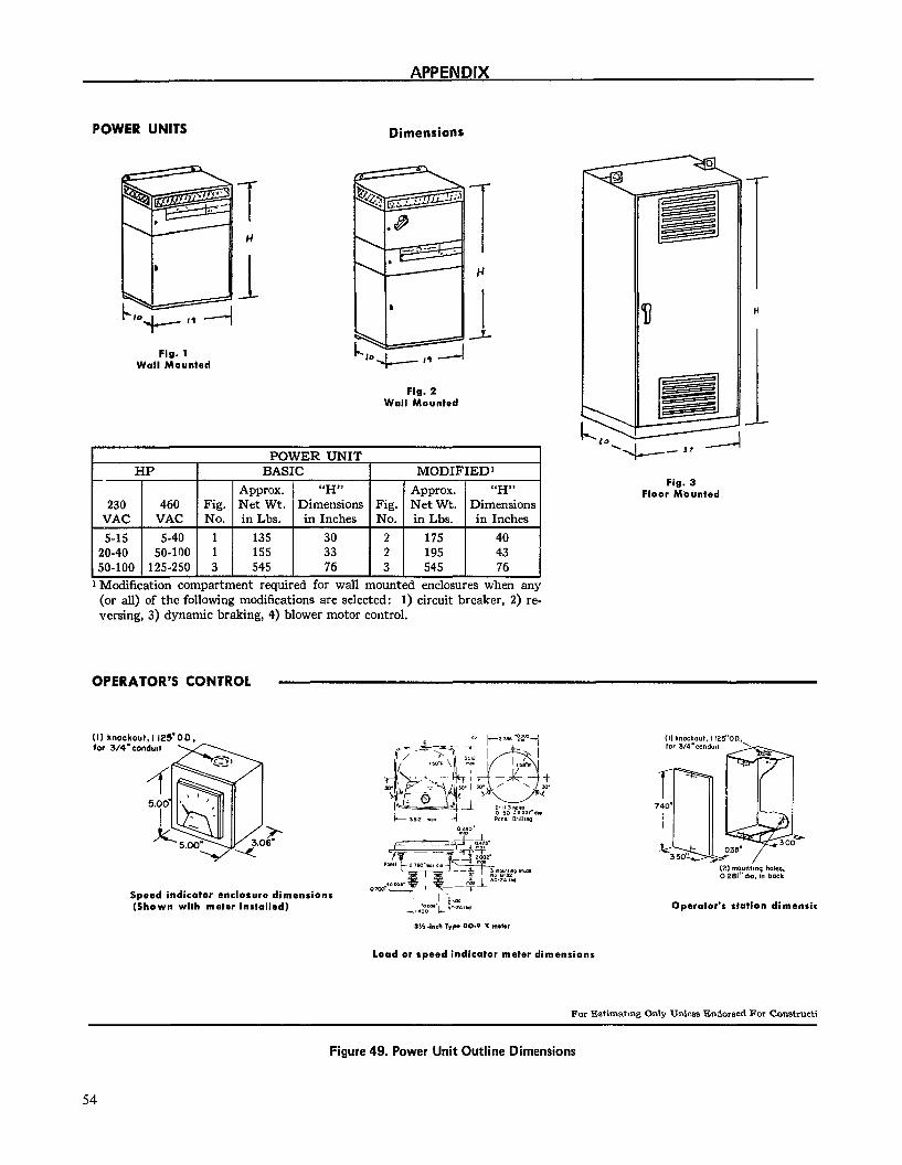
POWER UNITS Dimensions
Fig. 1 Wall Mounted
Fig. 2 Wall Mounted
POWER UNIT -.--- I m ------ I BASlC I MUlJ1.P rED1
1 ADD~OX. 1 “H” 1 1 Annrox. 1 “H” HP
I 230 460 Fig. Nki Wt. Dimensions Fig. N’e; Wt. Dimensions
VAC VAC No. in Lbs. in Inches No. in Lbs. in Inches 5-15 5-40 1 135 30 2 175 40
20-40 50-100 1 155 33 2 195 43 50-100 125-250 3 545 76 3 545 76 Modification compartment required for wall mounted enclosures when any (or all) of the following modifications are selected: 1) circuit breaker, 2) re- versing, 3) dynamic braking, 4) blower motor control.
Fig. 3 Floor Mbunted
OPERATOR’S CONTROL
(II knockout.1 125’00, for 3/4'condu1t
Speed indicator enclosure dimensions (Shown with meter installed) Operator’s station dimansis
Load or speed indicator meter dimensions
For Estimatmg Only Unless Endorsed For Constructi
Figure 49. Power Unit Outline Dimensions
54
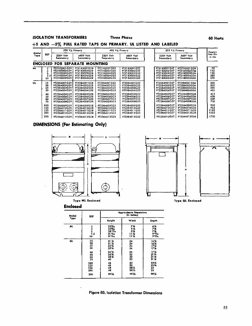
ISOLATION TRANSFORMERS Three Phase
+5 AND -5% FULL RATED VAPS ON PRIMARY. UL LISTED AND LABELED
Modal HP Typ*
I I
230 VA Primary 460 VA Primary 575 VA Primary
23OY Volt 4601 Volt 23OY Volt
I
46OY Volt Secondary Sseondory Secondary Secondary
I I
230Y Volt Sscondory
I
i6OY Volt Secondary
ENCLOSED FOR SEPARATE MOUNTING
60 Hertz
I Apprar Net Wt I I” Lbr
ML 2 3
;I 10”
PT21B3001G29 PT2lB300lG28 9lZlB3001 G23 9121 B3002G29 912lB3002G28 9T21 B3002G23 9T21 B3003G29 PT2183003828 9T2lB3003G23 9121 B3004G29 912183004628 9121 B3004G23 PT2183005629 9T2183005628 912183005623
912384001629 912384001 G28 9T2384001 G23 Pl2384002G29 9123B4002G28 972384007623 9123B4003G29 9T2304003G28 9T23B4003G23 912384004G29 9T23B4004G28 9T2384004G23 912384005G29 9T2384005G28 PT2384005G23 912384006G29 9123B4006G28 PT2384006G23 9123B4007G29 9123B4007G28 9T2384007623 9T2384008629 9T23B4008GZB 9T23B4008G23
912384009G29 912384009G28 9T2364009623 9123B4010G29 9T2384010628 PT23B401 OG23 912384011 G29 9’12384011 G28 9123B4011 G23 PT23B4012G29 912384012G28 9T2384012623 912384013G29 912384013628 912384013623
912lB3001 G22 912163001 G27 9T2183001 G26 9121B3002G22 912163002G27 9121B3002G26 9121 B3003G22 ’ 9T21 B3003G27 9121 B3003G26 9T2lB3004G22 9721 B3004G27 PT2183004626 9TZlB3005G22 PT2183005627 912183005G26
972384001 G22 972384002622 912384003622 912384004622
912384001 G27 PT2384002G27 972384003627 972384004627 9T2384005627 9T23B4006G27 PT23B4007G27 9T23B4008G27
9T2384001 G26 912384002626 972384003626 9T2384004026
912384005622 972384006622 972384007622 PT2384OOBG22
9T2384005G26 PT2384006G26 912384007626 972384008626
9T2384009G22 91238401 OG22 912384011 G22 912384012622
9T2384009627 91238401 OG27 9T23840: 1 G27 PT2384012G27 912384013627
9T2384009G26 9123B401OG26 9’12384011 G26 9T2384012626
912384013622 912384013626
:i 2s 30
:: 60 75
100 12.5 1.50 200 250
DIMENSIONS (For Estimating Only)
l----l
I H I
I- G
Type ML Enclosed Type 01 Enclosed
Enclosed Approximate Dim*ndonr
(in inchor] HP Mod.1
TYPO
ML
Height Depth
x ;5
10’
:i
3”;
40
2x 75
100 125 150 200
250
;: ;: 24
:; 32
:: 38% 38% 42%
QL
Figure 50. Isolation Transformer Dimensions
55
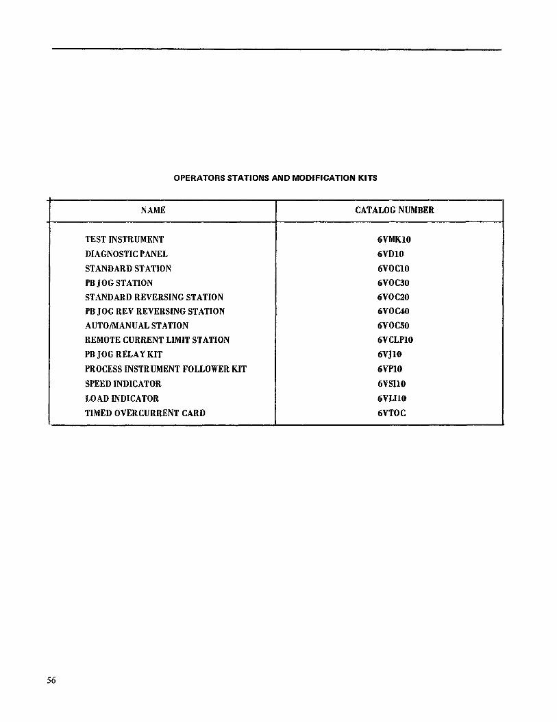
OPERATORS STATIONS AND MODIFICATION KITS
NAME CATALOGNUMBER
TESTINSTRUMENT 6VMKf0 DIAGNOSTICPANEL 6VDlO STANDARDSTATION 6VOClO PBJOGSTATION 6VOC30 STANDARDREVERSINGSTATION 6VOC20 PBJOGREVREVERSINGSTATION 6VOC40 AUTO/MANUALSTATION 6VOC50 REMOTECURRENTLIMITSTATION 6VCLPlO PBJOGRELAYKIT 6VJlO PROCESSINSTRUMENTFOLLOWERKIT 6VPlO SPEEDINDICATOR 6VSJlO LOADINDICATOR 6VLIlO TIMEDOVERCURRENTCARD 6VTOC
56

TABLE I PROGRAMMING HARDWARE ABBREVIATIONS
SYMBOLS
AMPLIFIERS ,__
J- = CASEGROUND
SIGNAL DEFINITIONS
SEBMF CRM OFP
+DR tEA0
EST FALT
tFC FOR FEA
KBS ILA IMET
XT tJOG
:“M”A”c” MSW
POTENTIOMETER ARROWS ON THE ‘+“r’A” CARD ELEMENTARY DIAGRAMS INDICATE THE WIPER DIRECTION + AS THE POTENTIOMETER SHAFT IS ROTATED CLOCKWISE TO INCREASE FUNCTION.
tVF9 tWFR
t -STAB ON TERMINAL
Cl -TERMINAL AT 2TB
t-TEST POINT ON DOOR FRONT
O” - SHIELDED OR TWISTED PA/R
MOOIFIMTIONS ,
MODIFICATIONS AND OPTIONS ARE INDICATED BY THE DASHED LINES. REFER TO THE RESPECTIVE SECTIONS IN THE INSTRUCTION BOOK FOR DETAILED CIRCUITS AND DESCRIPTIONS.
COUNTER EMF CURRENT FEEDBACK CROSSOVER MODIFY DELAYED FIRING POWER DRIVER REFERENCE ERROR AMP OUTPUT ;:i-:!“A’ FLT STOP INPUT
ki ._-.
. .ELD CURRENT FIELD DIAGNOSTIC REFERENCE FIELD ECONOMY ADJUST
EL0 FAULT )TOR CURRENT ABSOLUTE .-me..- * “‘,T AQJUST
UAL FOR METER PULSE
REF FROM OGC ITCH INPUT -ERENCE INPUT
ilt CbvtcN I LLM f.U&R~~T SIG1
LOCAL I
% E MAX CONTROL SIGNAL MODE SWITCH OSCILLATOR PHASE CONTROL REF DRIVE PRECONDITION PHASE SEQUENCE REGULATOR ERROR INTEGRATOR SUMMING JUNCTION REGULATOR SUMMING JUNCTION ;Eg;+ATOR RESPONSE ADJUST
READY-TO-RUN RUN SWITCH INPUT PHASE SYN OUTPUT SYSTEM FEEDBACK SPEED SIGNAL FOR METER SYSTEM REFERENCE INPUT SYSTFM FAllI T TRlP
?I
-hl REFEF VOLTAGE FEt WEAK FIELD I
- - .- - . . JTPUT FOR TACH TRIP ADJUST 4CH FAULT &CHOMETER FEEDBACK
----7ENCE IDBACK REFERENCE
f -UNCTION SE LOC JUMPERS
OH2 .-------. OH2 IC-400%
-500% -300%
RS-9V
MFC .--._---
X IFC IFC
S
!A-ZB. IIF USED .------------ NONE)
:NONEl -1HI
:-IL0 NONE)
J
9-2OV
OGR IOV
L zov
T.3-7SEC
V D A
2 -6OSEC
REG
X MCC
X MCC
X MCC
X IFC
X MCC
IFC
2
i I
.A I I c I .
: 3:
N C TACH
;RH-COM NONE)
IH-COM
(NONE)* + 32NROM LTI TO COI
T-CEMF, CC-CO ATI-AT2
ATI -AT2
T
T1 2
z 6
C TACH
ACH FILT ;CgO$S
-C-TC
6
1;
IS-/!XG- 0-160VOC
6-177VAC _------- IO-3OOVQC
?O -330VAc
IFC
IFC _--._--- If;C
--.-EC
---E >FC
.A3 < .25S NH RUN rnUP POS
NEG
MF MF MF MF MF MF MF(
OGC
MCC
X MCC
1
1
r ,.__ I
I.-! 1
t
:
:
IT-NTI, PT-PTI
(T-NT1 PT-PTI -----2------- IT-NTZ. PT-PTZ
?T~N_1LP_T_s.Z (T-NT3. PT-PT3
dT-NT3. PT-PT3 MFC OR MFE NONE YB-YO YA-YB YA-YB, YC-YO YA-YC YA-YC. YB-YO PA-QB 01-02 IIF USE01 CF-CFP.CPN-CO
CF-CFN,CFP-CO
X -INDICATE JUMPER CONNECTIONS SUPPLIED FOR A BASIC DRIVE SYSTEM.
t #FOR 193X530& MCC CARDS: LIN TIME .3-7SEC: LTI-LTZ Z-60 SEC: NO JUMPER USED
ELEMENTARY DIAGRAM
57

230/460VAC I I I
OTC ‘HSV
T
MOCIO
SPEED REF 2.5K
[&---&--;511SOL ,XFMR
‘g’ RUN COIL Y
t 19)
MAX ‘ji$RUN LATCtl 8,) ” 1 15 1111 (121
u
t 171 r-, JOG L-3
‘2 START RUN RUN 4
u , ‘2’ RUN u
,r,l-----iJoG
A- THESE TERMINALS SHOULD SE CONNECTED TO CONTROL POWER CKTS RATED ABOVE 30 VOLTS ONLY IF ENERQIZEO FROM POWER UNIT ZTSIO-2TSll.
SMET
NOTE 1. MAXIMUM PERMMAMBLE VOLTAQE:
115 VOLTS IF CONNECTED TO THE INTERNAL 115 VAC SUPPLY
SO VOLT8 IF CONNECTED TO AN EXTERNAL CONTROL CIRCUIT
NOTE 2. CUSTOMER TO CONNECT TO PROVIDE OVERLOAD PROTECTION AND TO PREVENT
STARTINQ OF MOTOR UPON DEVICE RESETTINQ.
ELEMEWfARY DIAGRAM 58
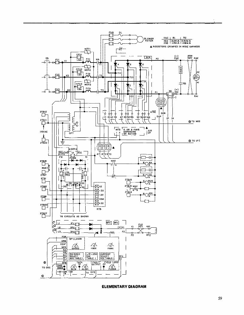
i CRIMPED IN WIRE HARNESS
t-1 ARM
IISVAC
2TG7 ZTGI
/I I- _ LB &OR i?&NS1
DEPENDING t
AIR ’ ’ 1 ON RATING 1 “’ --
@TO IFC
2TB27 \ I Y
TO CIRCUITS AS SHOWN
r- F2 RF2
ELEMENTARY DIAGRAM
59
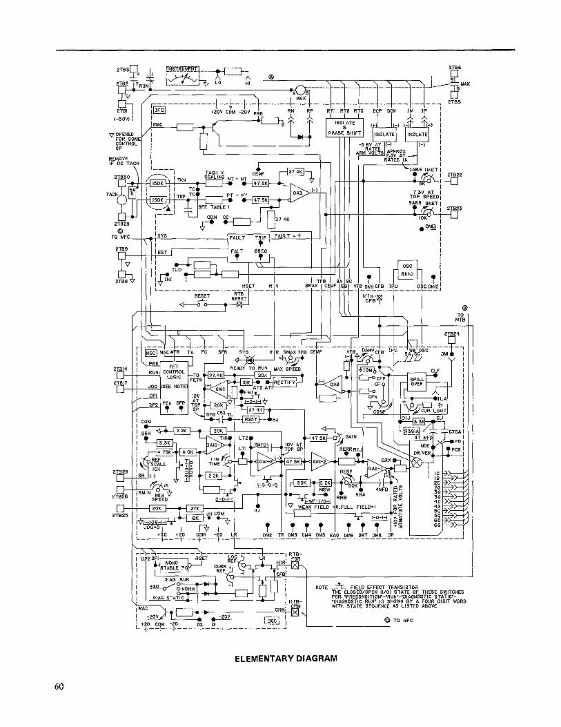
2TS6
I \\\ \\ \\!
_ “-----~-1---~--~---~---~-~~----~M*’
/,----------,--c-,-~-----*~~~-__ - __ - - _-- -_ - __ *zs
2TB23
v OPENED
%&Y OP
REMOVE IF DC TCICH
21829
6 TO MFC-
2T82f
I3
D 2TB2f
D 2TE2:
O.FULL FIELD=1
i I JH CUM
I+-JOG-l-l4 m-3 12K I - I .l f I -0-I-I l>$
- 0:
I JOG=O, I +30 ’ CP -40 +20
TITTTIT~TTI”~ : DM2 TR DM3 DM4 DMS EAO DMG DM7 DMG OR
i / L___~__-+_-+__,__iR_-___________________-------------------~
NOTE fr FIELD EFFECT TRANSISTOR THE CLOSED/OPEN II/O1 STATE OF THESE SWITCHES FOR ‘PRECONDITION’-‘RUN’-*DIAGNOSTIC STATIC’- ‘DIAGNOSTIC RUN’ IS SHOWN BY A FOUR DIGIT WORD WlTH STATE SEQUENCE AS LISTED ABOVE
Q TO WC
ELEMENTARY DIAGRAM
60
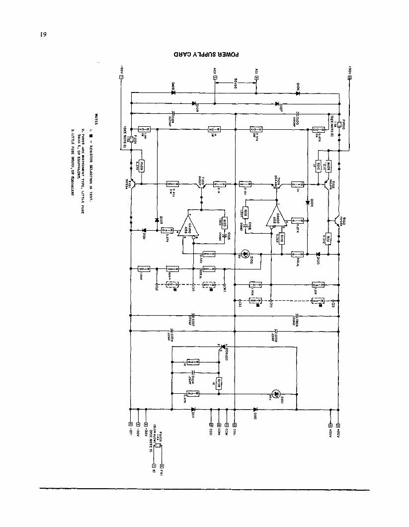
,?n
so,:
-
lHZi
80
12
mot
LO
10
- dHO
0 90
13'
(2 3
LON
33s
)
-
I 4HM
MI
0013
so
LO
-P
23v
I O
VA05
I I, 8 l
o*
010
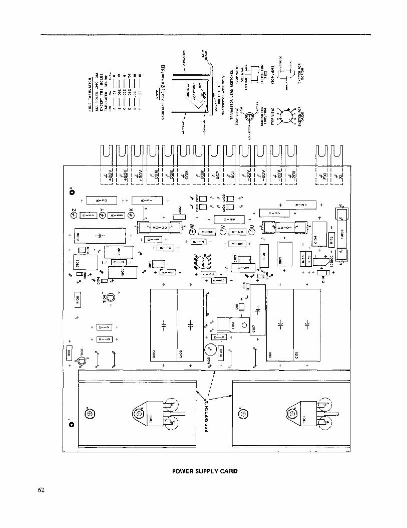
r--- c
L s.
i.v_
r---
tF
L +2
wiL
r---
-F 15
32v_
r---
l
4 1 -
w!-
r---
I CA
4 r---
F
L -&-
r---
I
+F
L CE-
r---
F
! -&-
r---
l
-c L
-AXI
-
r---
; -$3
v r---
CF
L 3x
r-T--
; -&
w r---
! &
-r -
‘I :
- +
SE
E S
KETC
H
“‘[\
\ \ 0 O
n +u
+ r: 1 : + r--- tF
L&i!-
I
r--- CF
IA
- <
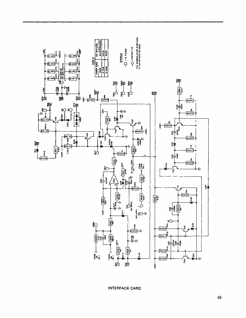
1
J
INTERFACE CARD
63
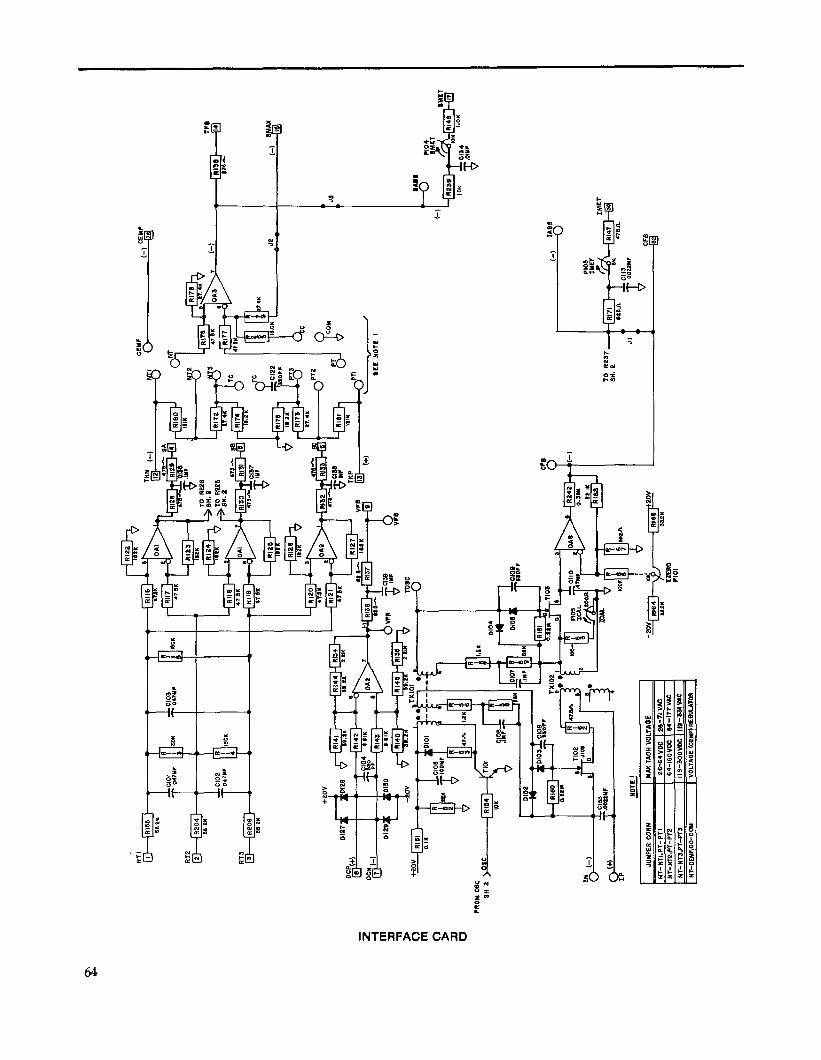
(-I
.TIO
S ,
I -1
(-I
IA0S
PI03
m
cr
00%
?“F
CF.3
IP
MO
IL
I
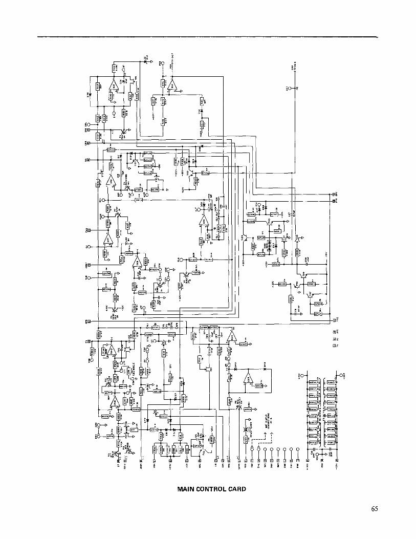
O- +
MAIN CONTROL CARD
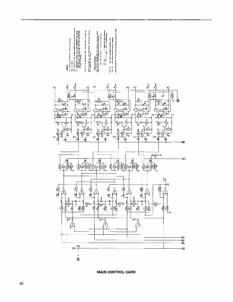
L
I I
t
I I
I I I I -I I
MAIN CONTROL CARD
66

AOZ-
WO
O
AOZ+
PPP i
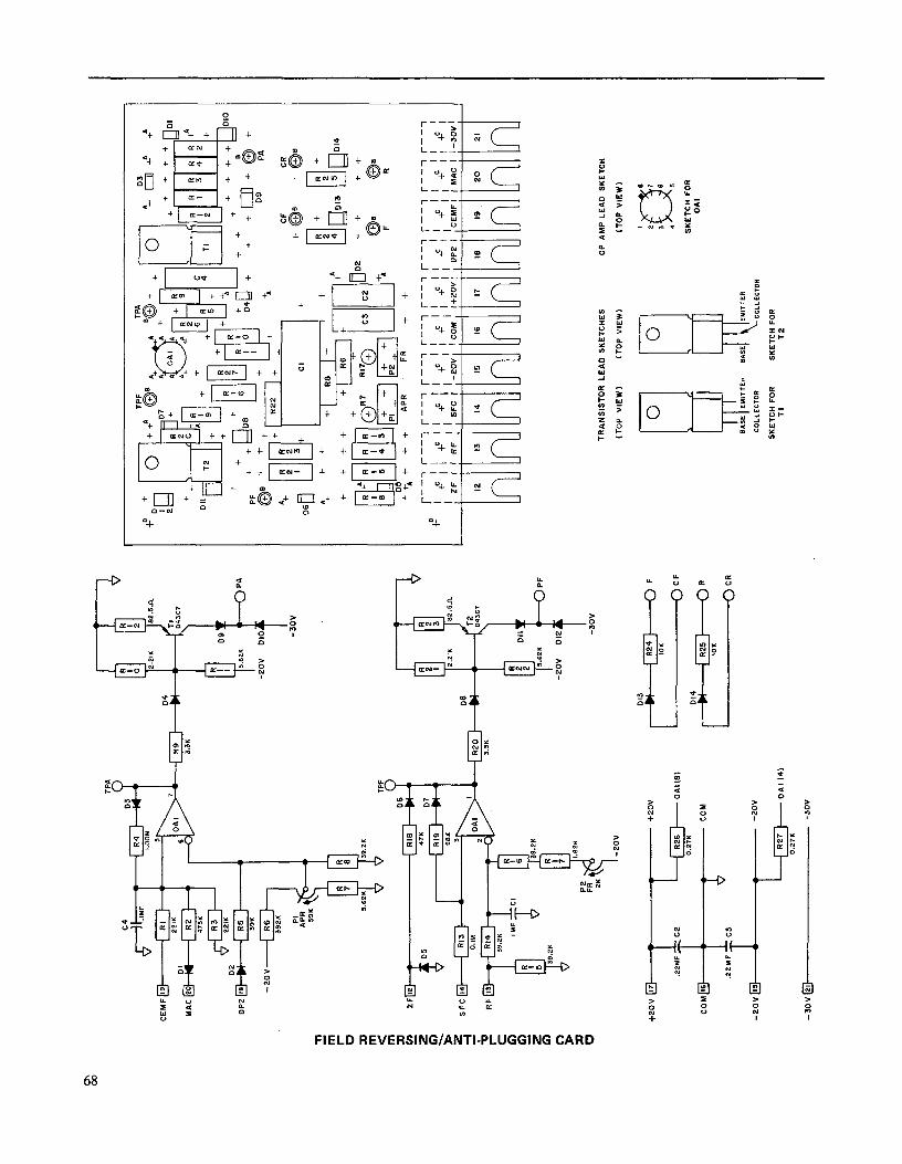
CEM
F
SFC
@
I-
TRAN
SIST
OR
LE
AD
SKET
CH
ES
OP
AM
P L
EAD
SK
ETC
H
(TO
P VI
EW)
ITO
P VI
EW)
(TO
P VI
EW)
+mv
0-7
+2ov
‘x3
8 e
7 3
6 4
5
SKET
CH
FO
R O
AI
SKET
CH
FO
R SK
ETC
H F
OR
TI
T2
0.27
K
-3ov
@
-3ov
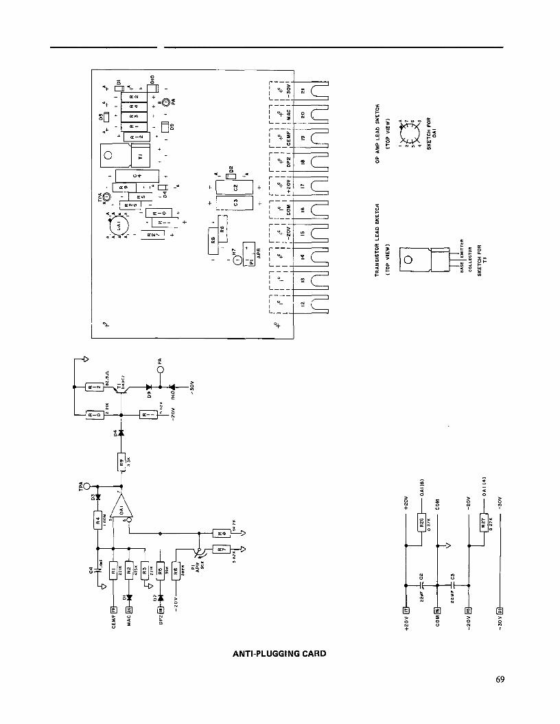
+I “0 I+ +
ANTI-PLUGGING CARD
69
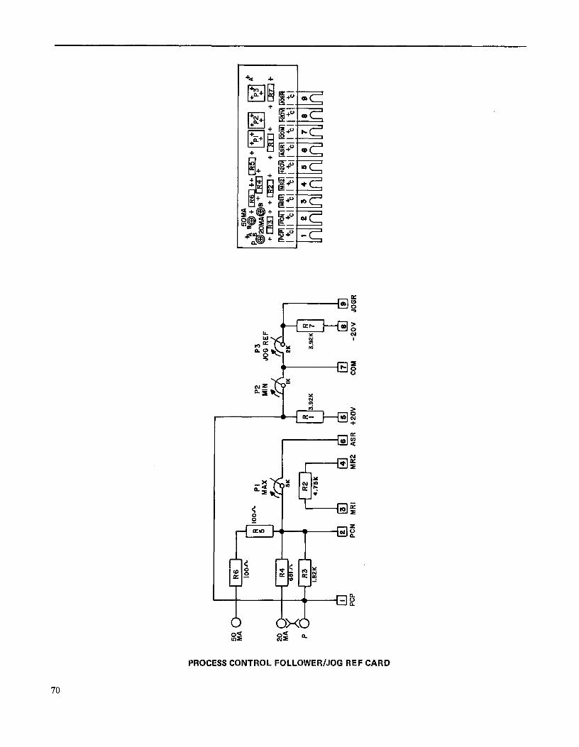
20
MA P
I3 i
I P2
ASR
+2OV
P3
JOG
REF
JOGR
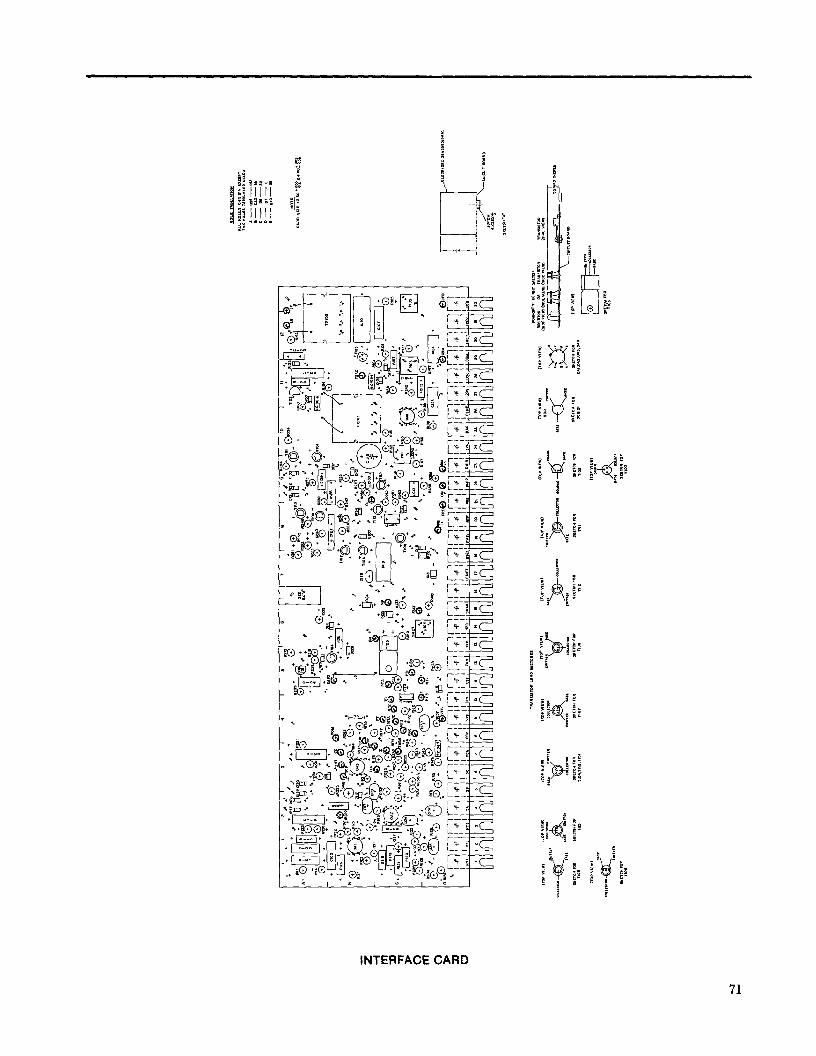
t
INTERFACE CARD
71
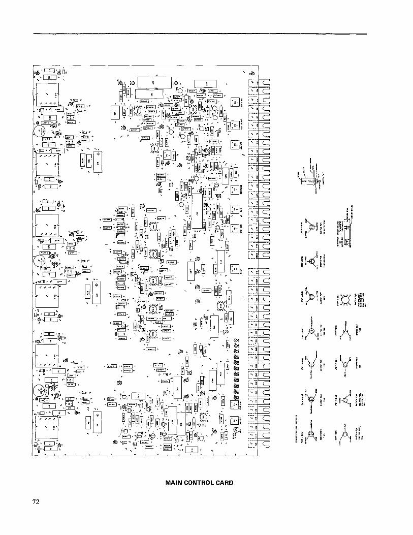
I I 4- f
MAIN CONTROL CARD
72
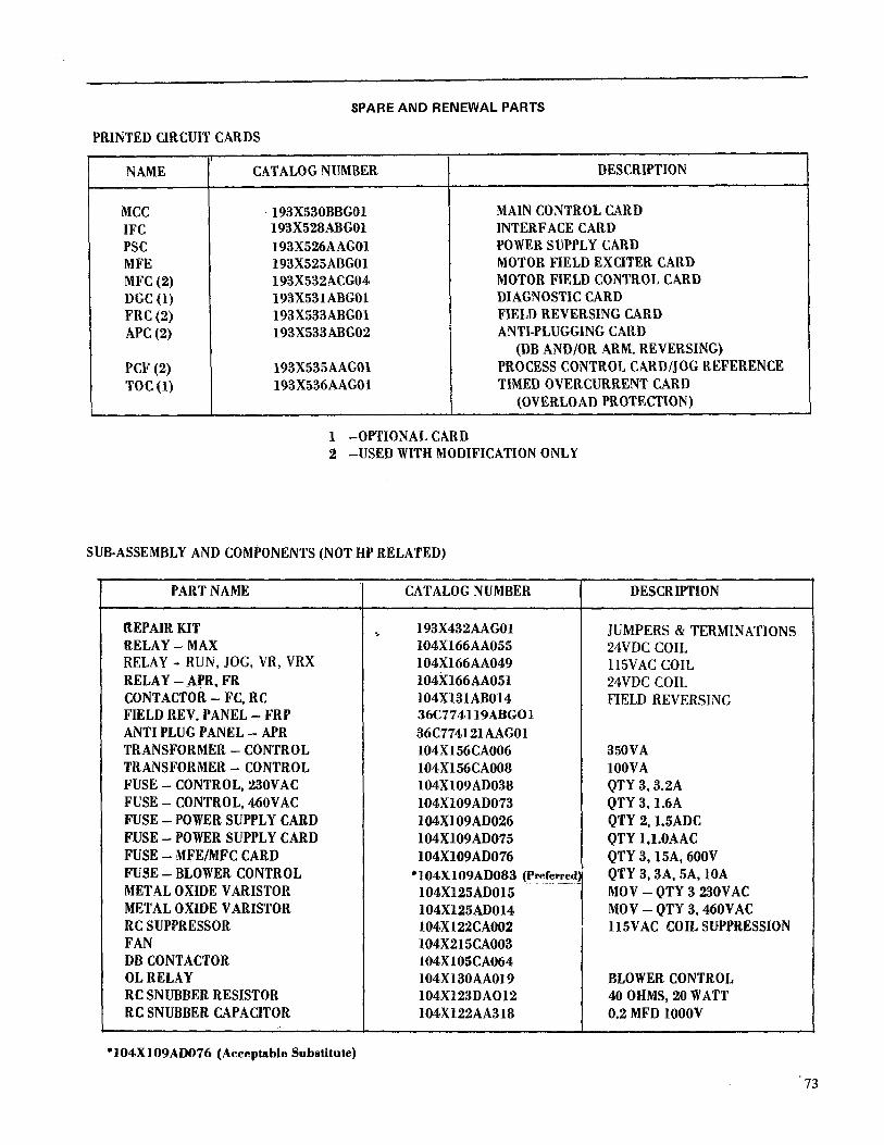
SPARE AND RENEWAL PARTS
PRINTEDCIRCUITCARDS
NAME
MCC IFC PSC MFE MFC(2) DGC(l) FRC(2) APC(2)
PCF(2) TOC(l)
CATALOGNUMBER
.193X530BBGOl 193X528ABGOl 193X526AAGOl 193X525ABGOl 193X532ACG04 193X531ABGOl 193X533ABGOl 193X533ABG02
193X535AAGOl 193X536AAGOl
DESCRIPTION
MAINCONTROLCARD INTERFACECARD POWERSUPPLYCARD MOTORFIELDEXCITERCARD MOTORFIELDCONTROLCARD DIAGNOSTICCARD FIELDREVERSINGCARD ANTI-PLUGGINGCARD
(DBAND/OR ARM.REVERSING) PROCESSCONTROLCARD/JOGREFERENCE TIMEDOVERCURRENTCARD
(OVERLOADPROTECTION)
1 -0PTIONALCARD 2 -USEDWITHMODIFICATIONONLY
SUB-ASSEMBLYAND COMPONENTS(NOTHPRELATED)
PARTNAME
REPAIRKIT RELAY-MAX RELAY - RUN, JOG, VR, VRX RELAY-.APR,FR CONTACTOR-FC,RC FIELDREV.PANEL-FRP ANTIPLUGPANEL-APR TRANSFORMER-CONTROL TRANSFORMER-CONTROL FUSE-CONTROL,230VAC FUSE-CONTROL,460VAC FUSE-POWERSUPPLYCARD FUSE-POWERSUPPLYCARD FUSE-MFE/MFCCARD FUSE-BLOWER CONTROL METALOXIDEVARISTOR METALOXIDEVARISTOR RCSUPPRESSOR FAN DBCONTACTOR OLRELAY RCSNUBBERRESISTOR RCSNUBBERCAPACITOR
CATALOGNUMBER
5 193X432AAGOl 104X166AA055 104X166AA049 104X166AA051 104X131AB014 36C774.119ABGOl 36C774121AAGOl 104X156CA006 104X156CA008 104X109AD038 104X109AD073 104X109AD026 104X109AD075 104X109AD076
*104X109AW83 (Preferre 104Xl25AD015 104X125AD014 104X122CA002 104X215CAOO3 104X105CA064 104X130AA019 104X123DA012 104X122AA318
DESCRIPTION
JUMPERS & TERMINATIONS 24VDC COIL 115VAC COIL 24VDC COIL FIELD REVERSING
350VA lOOVA QTY3,3.2A QTY 3.1.6A QTY 2,1.%ADC QTY I,l.OAAC QTY3,15A,600V QTY3,3A,5A,lOA MOV-QTY3230VAC MOV-QTY3,460VAC 115VAC COILSUPPRESSION
BLOWERCONTROL 40OHMS20WATT 0.2MFDlOOOV
l 104XlO9ADO76 (Acceptable Substitute)

SPAR
E AN
D RE
NEW
AL
PART
S
DR
IVE
HO
RSE
POW
ERR
ATIN
G,2
30VA
C/2
~VD
CN
EMA1
FOR
DR
IVES
WIT
HM
OD
ELN
UM
BER
END
ING
WIT
H---
-.~1
I PA
RTN
AME
CAT
ALO
GN
UM
BER
I
5
ACPO
WER
FUSE
,QTY
3 10
4X10
9AF
- - -
- -
005
MA
CO
NTA
CTO
R
104X
150C
A----
- 01
6
POW
ER C
ON
V. M
OD
ULE
36
D87
7201
- -
- - -
D
BGO
l
wi
GO
4
CIR
CU
IT
BREA
KER
10
4X20
4EA
- - -
- -
7%
7%
10
1 S
20
2.5
30
40
50
60
75
10
1 S
20
2.5
30
40
50
60
75
100
100
005
005
007
007
007
007
010
010
010
010
010
010
012
012
012
012
015
015
015
015
022
022
016
016
017
017
017
017
018
018
018
018
018
018
019
019
019
019
020
020
020
020
020
020
DBG
OI
DBG
Ol
DBG
Ol
DBG
Ol
DBG
02
DBG
02
CBG
Ol
CBG
O2
CBG
02
CBG
03
CBG
O:
DBG
OI
DBG
Ol
DBG
Ol
DBG
Ol
DBG
02
DBG
02
CBG
Ol
CBG
O2
CBG
02
CBG
03
CBG
O:
iBG
O2.
ABG
OI A
BG02
ABG
02 &
GO
B IA
CG
O%
IAAC
;O~A
AGO
~\AA
GO
~ iB
GO
2. AB
GO
I ABG
02 A
BG02
&G
OB
IAC
GO
%IA
AC;O
~AAG
O~\
AAG
O~
AAG
Oq'
AAa:
. ..
I AA
GO
q'AA
a:
GO
4 G
O4
GO
5 G
O5
GO
7 G
O7
GO
7 G
O7
GO
7 G
O7
GO
9 G
O9
G09
. G
O9
G09
. G
O9
GO
3 G
O3
GO
3 G
O3
GO
3 G
O3
GO
2 G
O2
GO
2 G
O2
GO
1 G
O1
GO
1 G
O1
GO
1 G
O1
GO
1 G
O1
(0
(0
(21
(21
(2)
(2)
003
003
016
016
003
003
(3)
(3)
(3)
(3)
(3)
(3)
(3)
(3)
(3)
(3)
(3)
(3)
(3)
(3)
(3)
(3)
011
011
bll
bll
043
043
042
042
009
009
031
031
031
031
046
046
I I
I I
I I
I I
I I
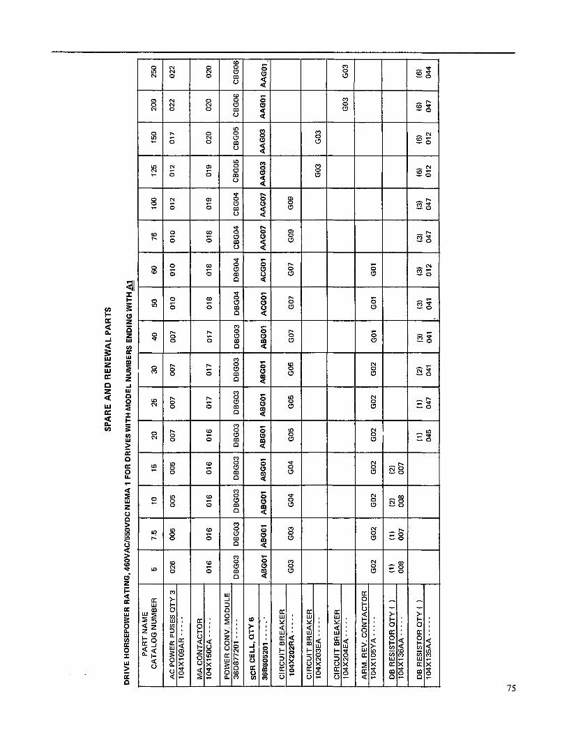
SPAR
E AN
D RE
NEW
AL
PART
S
DRIV
E HO
RSEP
OWER
RA
TING
, 46
0VAC
/550
VDC
NEMA
1
FOR
DRIV
ES
WITH
MO
DEL
NUMB
ERS
ENDI
NG
WIT
H&
-
PART
NA
ME
CATA
LOG
NUM
BER
5 7.
5 10
15
20
25
30
40
50
60
75
10
0 12
5 15
0 20
0 25
0
AC
POW
ER
FUSE
S QT
Y 3
026
005
005
005
007
007
007
007
010
010
010
012
012
017
022
022
104X
109A
R----
-
016
017
017
017
018
018
018
019
019
020
020
020
DBGO
B DB
GOB
DBGO
B DB
GOB
DBG0
4 DB
G04
CBGO
4 CB
G04
CBGO
S CB
G05
CBGO
G CB
GOG
ABGO
I ,
ABGO
I , A
BGOI
, A
BGOI
,
ACGO
I I
ACGO
I IA
AGO~
1 A
AG07
IA
AGO~
lA
AGO
3 1 A
AGO
1 AAG
OI
,I
I -~
~~ I
I
T I
I I
I I
I I
I I
I I
I I
I CI
RCUI
T BR
EAKE
R
104X
ZOZR
A----
- GO
3 GO
3 GO
4 GO
4 GO
5 GO
5 GO
5 GO
7 GO
7 GO
7 GO
9 GO
9
CIRC
UIT
BREA
KER
104X
203E
A -
- -
- -
GO3
GO3
GO2
GO2
GO2
(1)
(1)
(2)
008
007
008
GO2
GO3
GO3
GO3
GO2
GO2
1 GO
2 1
GO2
1 GO
1 1
GO1
I GO
1 I
GO2
GO2
GO1
GO1
GO1
I I
I I
I I
(1)
(1)
(2)
13)
(3)
(3)
(3)
(3)
(6)
(6)
(6)
045
047
041
041
041
012
047
047
012
012
047

SPAR
E AN
D RE
NEW
AL
PART
S
PAR
T NAM
E C
ATAL
OG
NU
MBE
R
ACPO
WER
FUSE
,QTY
3 10
4X10
9AG
.----
-
MAC
ON
TAC
TOR
104X
105C
B---
---
MAC
ON
TAC
TOR
10
4X15
0XE-
----
-
POW
ERC
ON
V.M
OD
ULE
36
D87
7201
----
-
5 7%
10
15
20
25
30
40
50
60
75
10
0
005
005
007
007
009
009
015
015
015
021
021
025
001
001
002
003
004
005
006
009
010
GO
3 G
O3
GO
3
DC
G05
DC
GO
l DC
GO
l DC
GO
l DC
GO
l DC
G02
DC
G02
CBG
Ol C
BGO
S CBG
OZ C
BGO
S CBG
OZ
SCR
CEL
LQTY
6 AB
G03
ABG
02 A
BG02
ABG
OZ A
BG02
AC
GO
Z AC
G02
AAG
08 A
AGO
AAG
O A
AGO
Z AAG
O:
36B6
0520
1---
--
CIR
CU
ITBR
EAKE
R
GO
4 G
O4
GO
5 G
O7
GO
7 G
O7
GO
9 G
O9
104X
202E
A---
--
MO
LDED
CAS
ESW
ITC
H
GO
5 G
O5
104X
203E
A---
--
MO
LDED
CAS
ESW
ITC
H
GO
5 G
O:
104X
204E
A---
--
ARM
.REV
.CO
NTA
CTO
R
GO
2 G
O2
GO
2 G
O1
GO
1 G
O1
GO
1 10
4XlO
SYA-
----
DBR
ESIS
TOR
,QTY
( )
(1)
(1)
(2)
(2)
104X
136A
D--
---
016
003
'316
00
3
DBR
ESIS
TOR
,QTY
( )
(3)
(3)
(3)
(3)
(3)
(3)
(3)
(3)
104X
135A
A.--
--
011
011
043
042
009
031
031
046
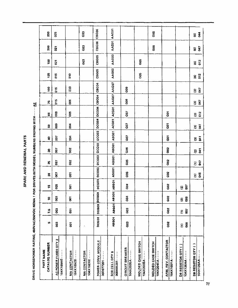
SPAR
E AN
D RE
NEW
AL
PART
S
DRIV
E HO
RSEP
OWER
RA
TING
, 46
0VAC
/%OV
DC
NEMA
1
FOR
DRIV
ES
WITH
MO
DEL
NUMB
ERS
ENDI
NG
WITH
- -
- -
- 82. -
L
1 1 3 I
I
PART
NA
ME
CATA
LOG
NUMB
ER
5 I
7.5
1 1 25
30
10
50
60
15
20
-- 00
7 AC
PO
WER
FU
SES
QTY
3 00
3
I I 00
3
, 10
4X10
9AG-
----
003
009
009
007
007
001
004
004
005
006
010
001
X003
DC
GO:
DCGO
O
ABGO
l AB
GOl
ABGO
l
DCGO
: CB
GO4
CBG0
4
AAG0
7 AA
G07
t GO9
GO9
OCG0
4
ACGO
I
DCG0
4
ACGO
I AB
GO’
GO4
GO4
GO5
GO5
GO5 ---l--
GO
7 GO
7 GO
7
I MOL
DED
CASE
SW
ITCH
I
I GO
5 GO
5 10
4X20
3EA
- - -
- -
I I
GO2
GO2
-t-
1 MO
LDED
CA
SE
SWIT
CH
104X
204E
A----
- I
I
I 1
GO5
1 GO
5 1
GO2
GO2
GO2
GO1
GO1
GO1
13)
D12
(3)
041
12)
(2)
008
007
4--
(3)
(3)
(1)
045
(3)
041
DB
RESI
STDR
CI
TY
( 1
104X
135A
A--
_ - -
(6)
(6)
IS)
(6)
012
012
047
044
(1)
(2)
647
041
D47
1047

RECOMMENDED POWER STUD WIRING & TERMINALS
CRIMPING TOOLS FOR POWER STUD WIRING TERMINALS
TERMINAL
Solistrand
Solistrand
ELECTRO-HYDRAULIC POWER UNIT 115VAC
AMP CAT. NO.
HEAD DIE CAT. NO. CAT. NO.
69120-l 69065 46322-2
69120-l 69065 46323-2
69120-l 69065 46324-2
69120-l 69065 46325-2
69120-l 69060 46326-2
69120-l 69060 46327-2
l-l/O AWG
2/O AWG
3/O AWG
4/O AWG
250 MCM
300 MCM
Solistrand
Solistrand
Solistrand
Solistrand
AMPower
AMPower
78
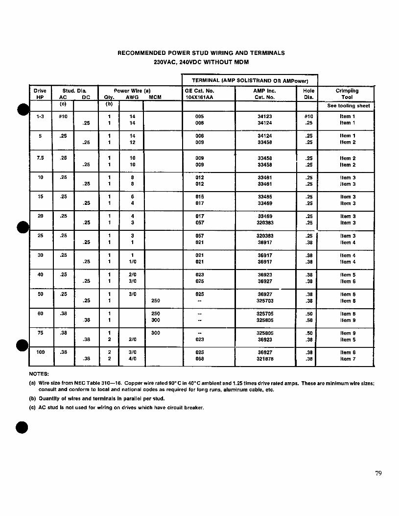
RECOMMENDED POWER STUD WIRING AND TERMINALS
230VAC, 240VDC WITHOUT MDM
NOTES:
(a) Wire size from NEC Table 310-16. Copper wire rated 90°C in 40°C ambient and 1.25 times drive rated amps. These are minimum wire sizes; consult and conform to local and national codes as required for long runs, aluminum cable, etc.
(b) Quantity of wires and terminals in parallel per stud.
(c) AC stud is not used for wiring on drives which have circuit breaker.
79

RECOMMENDED POWER STUD WIRING AND TERIUMNALS 46OVAC, 550VDC WITHOUT MDM
1 TERMINAL (AMP SOLISTRAND OR AMPower)
NOTES:
Hole Dia.
#lo .25
.25
.25
.25
.25
.25
.25
.25
.25
.25
.25
.25
.25
.25
.38
.38
.38
.38
.38
.38
.38
-50 .38
.38
.38
.38
.50
(a) Wire stre from NEC Table 310-18. Copper wlre rated 90°C in 40°C ambient and 1.25 times drive rated amps. These are minimum wire sizes; consult and conform to local and nattonal codes as requlred for long runs, aluminum cable, Me.
(b) Quantlty of wires and terminals In parallel per stud.
(c) AC stud Is not used for wiring on drive3 which have circuit breakcr.
80
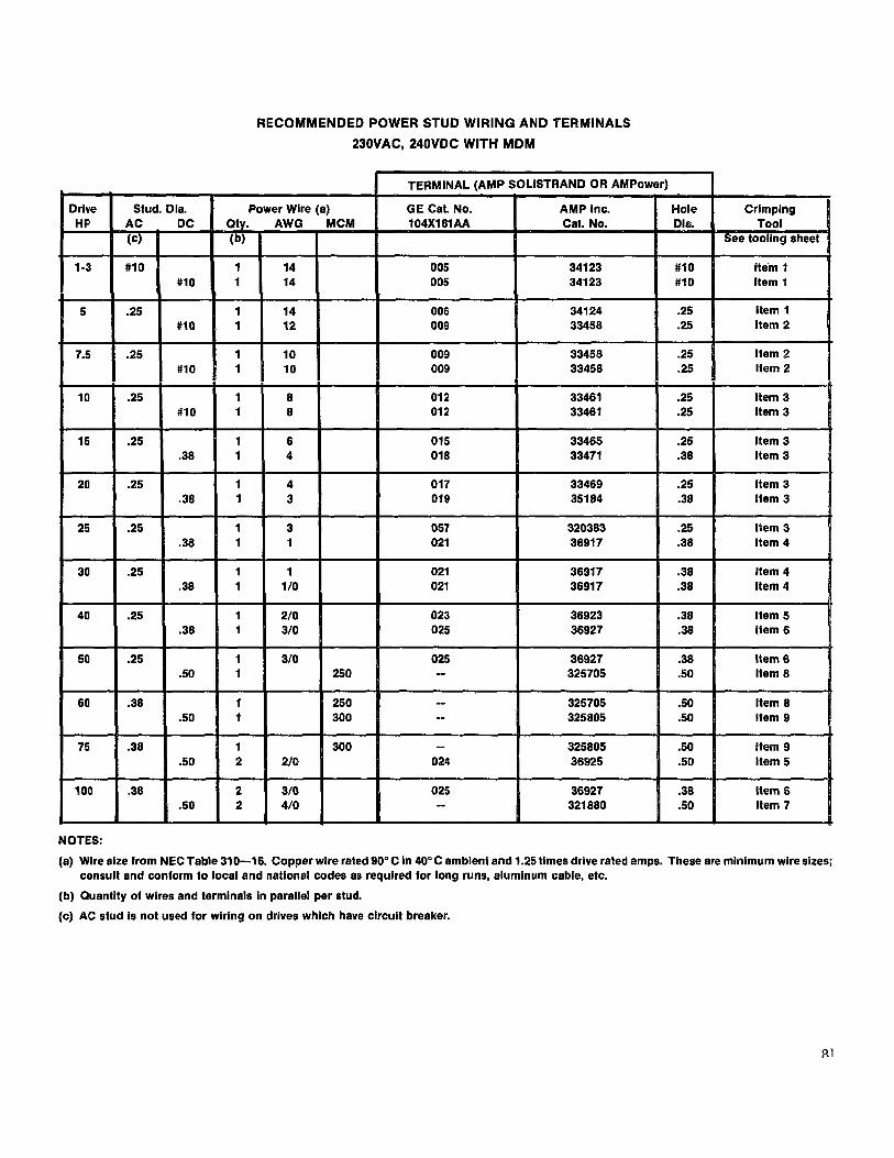
AND TERMINALS
23OVAC, 240VDC WITH MDM
NOTES:
(a) Wlre size from NEC Table 310-16. Copper wlre rated 90°C In 40” C amblent and 1.25 times drive rated amps. These are mlnimum wlre sizes; consult and conform to local and national codes as requlred for long runs, aluminum cable, etc.
(b) Quantlty oi wires and terminals in parallel per stud.
(c) AC stud is not used for wiring on drives which have circuit breaker.
81

460VAC, 550VDC WITH MDM
TERMINAL fAMP SOLISTRAND OR AMPower) I
NOTES:
(a) Wire sire from NEC Table 310-16. Copper wire rated 96°C in 40°C ambient and 1.26 times drive rated amps. These are minimum wire sizes; consult and conform to local and national codes as required for long runs, aluminum cable, etc.
(b) Quantity of wires and terminals in parallel per stud.
(c) AC stud is not used for wiring on drives which have circuit breaker.
82
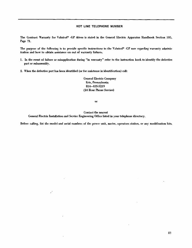
HOT LINE TELEPHONE NUMBER
The Contract Warranty for Valutrol * -GP drives is stated in the General Electric Apparatus Handbook Section 105, Page 71.
The purpose of the following is to provide specific instructions to the Valutrol * -GP user regarding warranty adminis- tration and how to obtain assistance on out of warranty failures.
1. In the event of failure or misapplication during “in warranty” refer to the instruction book to identify the defective part or subassembly.
2. When the defective part has been identified (or for assistance in identification) call:
General Electric Company Erie, Pennsylvania 814-455-3219
(24 Hour Phone Service)
or
Contact the nearest General Electric Installation and Service Engineering Office listed in your telephone directory.
Before calling, list the model and serial numbers of the power unit, motor, operators station, or any modification kits.
83

GLOSSARY OF TERMS
Page ACM - Auxiliary Control Module ........................................................ .58 ALIGN - Tachometer Loss Align Adjustment ......................................... 12,30,36,39 A’PC - Anti-plugging Card. .............................................................. 11 APR - Anti-plugging Relay. ........................................................... 35,43 ASR-PCFOutput .....................................................................
CEMF -CounterEMF ...................................................... .10,11,15,57,72 COM - Regulator Common. ....................................................... .15,17,72 COMP - IR Compensation Adjustment. .......................................... .12,35,36,39,40 CPT Control Power Transformer. ..................................................... 10,ll CFB-.CurrentFeedback ................................................ ..10,15,31,35,57,7 2 CUR REF - Diagnostic Current Reference Potentiometer. ........................................ .35 CROSS - Crossover Adjustment ....................................................... 14,39 CUR LIMIT - Current Limit Adjustment ............................................ 12,35,39,40
DA1 - Positive Armature Connection (ACM). .............................................. 14,22 DA2 - Negative Armature connection (ACM) .............................................. 14,22 DAMP - Dampening Adjustment. ................................................... .12,35,40 DB - Dynamic Braking Contactor ........................................... :, ............ .35 Diagnostic - Normal ............................................................... 29,36 Diagnostic - Run ................................................................... .36 Diagnostic - Static .................................................................. .35 DGC-DiagnosticCard .......................................................... .11,14,15 DMl-DM8 Dummy Input/Output points. .............................................. .15,4C, 72 DPl-DP2 Diagnostic Switching signals. ................................................ .15,36,72 DR-DriverReference ...................................................... .lO, 15,36,57,72
EAO -Error Amplifier Output ................................................... 15,35,57,72 EST - External Fault Stop ........................................................... 17,57
F - Forward Armature Reversing Contactor. .................................................. .43 Fl-F2 -Motor Field Connections ...................................................... 15,29 FC -FieldCurrent ............................................................. .15,57,72 FC - Forward Field Reversing Contactor. .............................................. .15,57,72 FDR - Field Diagnostic Reference. ..................................................... 35,57 FEA - Field Economy Adjust. ........................................................ 44,57 FF-FieldFault.....................................................................5 7 FLOSS - Field Loss Adjustment ....................................................... 39,40 FMAX -Motor Field Maximum Adjustment ................................................. .36 -- FMIN -Motor Field Minimum Adjustment ................................................ 36,39 m- Field Reversing Card .......................................................... 11,44
GAIN - Speed Loop Gain Adjustment ................................................ .12,35,40
IABS - Current Signal. ............................................................. 45,57 IFC -1nterfaceCard ............................................................ .ll, 13,34 ILA - Current Limit Reference. ....................................................... 48,57 IMET - Current (Load) Instrument Output and Adjustment ...................... 13, 17,36,39,40,48,49,57 WInitialPulse.. ..................................................... 15,31,35,36,57,72
JOG-JogSwitchInput ........................................................ 15,18,57,72
Test Points Located on Door Front (See MCC Illustration, Fig. 5 and Fig. 9).
84
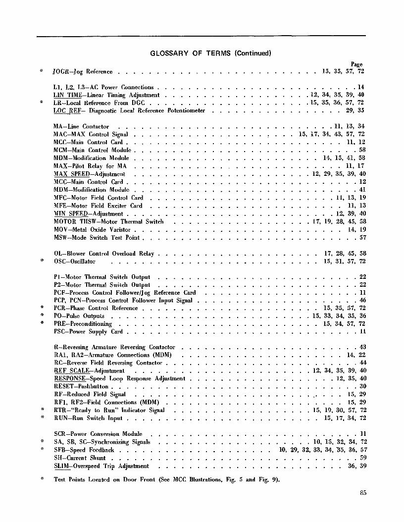
GLOSSARY OF TERMS (Continued)
??ze JOGR-Jog Reference .......................... 15, 35, 5,7, 72
Ll, L2, L3-AC Power Connections .......................... 14 LIN TIME-Linear Timing Adjustment ................... 12, 34, 35, 39, 40 LR-Local Reference From DGC ..................... 15, 35, 36, 57, 72 LOC REF- Diagnostic Local Reference Potentiometer ................. 29, 35
MA-Line Contactor ............................ 11, 13, 34 MAC-MAX Control Signal ................. I ... 15, 17, 34, 43, 57, 72 MCC-Main Control Card ............................ 11, 12 MCM-Main Controt Module ............................. 58 MDM-Modification Module ........................ 14, 15, 41, 58 MAX-Pilot Relay for MA ........................... 11, 17 MAX SPEED-Adjustment ....................... 12, 29, 35, 39, 40 MCC-Main Control Card .............................. 12 MDM-Modification Module ............................. 41 MFC-Motor Field Control Card ........................ 11, 13, 19 MFE-Motor Field Exciter Card ......................... 11, 13 MIN SPEED-Adjustment ........................... 12, 39, 40 MOTOR THSW-Motor Thermal Switch .................. 17, 19, 28, 45, 58 MOV-Metal Oxide Varistor ........................... 14, 19 MSW-Mode Switch Test Point ............................ 57
OL-Blower Control Overload Relay ..................... 17, 28, 45, 58 OSC-Oscillator ........................... 15, 31, 57, 72
Pl-Motor Thermal Switch Output .......................... 22 P2-Motor Thermal Switch Output .......................... 22 PCF-Process Control Follower/Jog Reference Card .................... 11 PCP, PCN-Process Control Follower Input Signal ..................... 46 PCR-Phase Control Reference ....................... 15, 35, 57, 72 PO-Pulse Outputs .......................... 15, 33, 34, 35, 36 PRE-Preconditioning .......................... 15, 34, 57, 72 PSC-Power Supply Card .............................. 11
R-Reversing Armature Reversing Contactor ....................... 43 RAl, RAB-Armature Connections (MDM) ..................... 14, 22 RC-Reverse Field Reversing Contactor ......................... 44 REF SCALE-Adjustment ....................... 12, 34, 35, 39, 40 RESPONSE-Speed Loop Response Adjustment ................... 12, 35, 40 RESET-Pushbutton ................................ 30 RF-Reduced Field Signal ............................ 15, 29 RFl, RFB-Field Connections (MDM) ....................... 15, 29 RTR-“Ready to Run” Indicator Signal .................. 15, 19, 30, 57, 72 RUN-Run Switch Input ......................... 15, 17, 34, 72
SCR-Power Conversion Module ........................... 11 SA, SB, SC-Synchronizing Signals .................... 10, 15, 32, 34, 72 SFB-Speed Feedback .................... 10, 29, 32, 33, 34, 35, 36, 57 SH-Current Shunt ................................ 59 SLIM-Overspeed Trip Adjustment ........................ 36, 39
Test Points Located on Door Front (See MCC Illustrations, Fig. 5 and Fig. 9).
85
GLOSSARY OF TERMS (Continued)
it SMAX-Maximum Speed Adjustment and Output .................... 15,72 SMET-Speed Instrument Output and Adjustment ............... 13, 17,39,40,48,57 SMIN-Minimum Speed Reference Adjustment and Input ................ 15,17, 72 SGpeed Reference ....................... 10, 15,17,29,34,57, 72 SYS-System Fault Trip .......................... 15,30,57, 72
TA-Tachometer Align Output ......................... 15,57,72 TFB-Tachometer Feedback Signal ..................... 15,33,35, 57, 72 THSW-Drive Thermal Switch ........................ 28,45,58,59 TKN-Negative Tachometer Input .......................... .18 TKP-Positive Tachometer Input ............................ 18 TOC-Timed Overcurrent Card ......................... 11,30,47 TR-Timed Reference ........................ 10,15,34,35,57,72
VFB-Voltage Feedback . . . . . . . . . . . . . . . . . . . . . . . 10,15,31,35,57,72
WFR-Weak Field Reference . . . . . . . . . . . . . . . . . . . . . . . . . . 15,57, 72
ZF-Zero Field Signal . . . . . . . . . . . . . . . . . . . . . . . . . . . . . . .59
* Test Points Located on Door Front (See MCC Illustration, Fig. 5 and Fig. 9).
86


GENERAL ELECTRIC COMPANY SPEED VARIATQR PRODUCTS OPERATION
ERIE, PENNSYLVANIA 66531
GENERAL QEK-24988B (4186) 1M (P)