Embed Size (px)
Citation preview
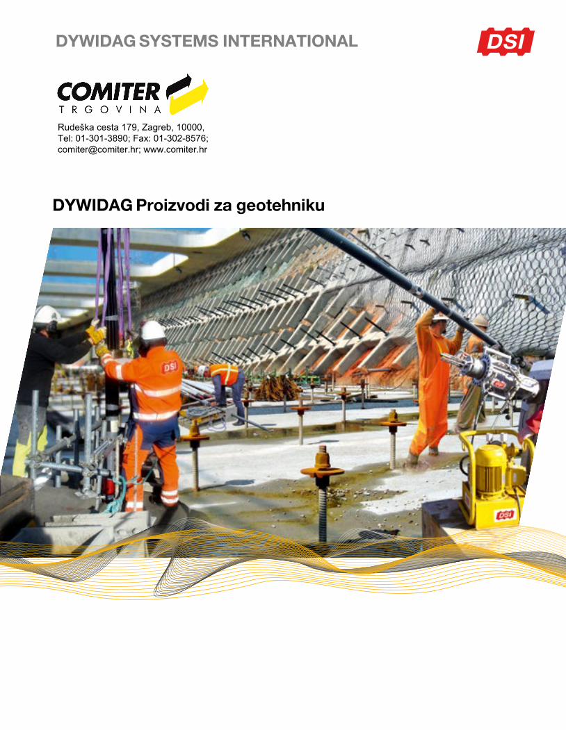
DYWIDAG Proizvodi za geotehniku
DYWIDAG SYSTEMS INTERNATIONAL
Rudeška cesta 179, Zagreb, 10000, Tel: 01-301-3890; Fax: 01-302-8576; [email protected]; www.comiter.hr
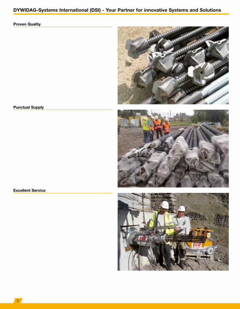
DYWIDAG-Systems International (DSI) - Your Partner for innovative Systems and Solutions
Excellent Service
Punctual Supply
Proven Quality
2
Contents
About Us ..............................................................................................................................4
Fields of Application ..........................................................................................................6
DYWIDAG Threadbar AnchorsBasic Concept & Key Features.............................................................................................8Technical Data ......................................................................................................................9Permanent Anchors & Temporary Anchors ........................................................................10Removable Temporary Anchors .........................................................................................11References .........................................................................................................................12
DYWIDAG Strand AnchorsBasic Concept & Key Features...........................................................................................14Technical Data ....................................................................................................................15Permanent Anchors & Temporary Anchors ........................................................................16Removable Temporary Anchors .........................................................................................17Permanent Anchors with Double Sheathing – TWIN-Corr System ....................................17Electrically Testable Permanent Anchors – El-Iso System .................................................18Permanent Anchors with Multiple Head .............................................................................18References .........................................................................................................................19
GEWI® Pile / GEWI® Plus PileBasic Concept & Key Features...........................................................................................22Technical Data ....................................................................................................................23Standard Corrosion Protection (SCP) ................................................................................24GEWI®-Multibar Pile ...........................................................................................................24Double Corrosion Protection (DCP)....................................................................................25References .........................................................................................................................26
DYWIDAG Soil NailsBasic Concept & Key Features...........................................................................................28Technical Data ....................................................................................................................29Permanent & Temporary Soil Nails .....................................................................................30References .........................................................................................................................31
DYWIDAG Rock BoltsSN Anchors & Expansion Shell Anchors ............................................................................32References .........................................................................................................................33
DYWI® Drill Hollow Bar SystemBasic Concept & Key Features...........................................................................................34Temporary Bolt & Semi Permanent Bolt .............................................................................35Technical Data ....................................................................................................................35References .........................................................................................................................36
DYWIDAG Tie RodsBasic Concept & Key Features...........................................................................................40Corrosion Protection Systems ...........................................................................................41Technical Data ....................................................................................................................41Tie Rod Connections ..........................................................................................................42Waler Bolt ...........................................................................................................................43References .........................................................................................................................44
The GEWI® System – Connecting ReinforcementBasic Concept & Key Features...........................................................................................46Technical Data ....................................................................................................................47
The FLIMU® System – Connecting ReinforcementBasic Concept ....................................................................................................................48Technical Data ....................................................................................................................49References .........................................................................................................................50
DYWIDAG EquipmentDYWIDAG Jacks, Technical Data ......................................................................................52Hollow-Piston CFRP Cylinders, Technical Data .................................................................53Tensioning Accessories & Force / Displacement Measurement ........................................54Torque Equipment, Technical Data .....................................................................................55
3

About Us
The origins of DYWIDAG-Systems International (DSI) date back to the founding of Dyckerhoff & Widmann AG (DYWIDAG) in 1865, and thus, back to the beginning of industrial construction. As a recognized market leader in Geotechnics in Germany and Europe, DSI offers all established systems in specialized civil engineering. The product range includes ground anchors, micropiles and soil and rock bolts. GEWl® and GEWl® Plus Threadbars that are threadable along their entire lengths, tensioning bars, DYWI® Drill Hollow Bars and prestressing steel strands that are used as load-bearing tendons.
Thanks to our long-term experience in the development, approval, production and application of geotechnical products, we can guarantee you as our clients high quality products and systems that fulfill the highest standards of quality.
As leaders in innovation, we have been offering you a comprehensive product range of technically sophisticated solutions for decades. We promote new technical developments and research projects. Global patent applications are proof of our leading position and form the foundation of our successful work – to your benefit.
Customized special solutions and adaptations of our products are developed by competent and experienced engineers in our technical specialist departments just-in-time in a practice-oriented way.
As permanent members in the relevant committees of experts and standards, we continuously advance technical developments as well as the safety and application of our products and systems. Wherever required, we also offer support for approvals in individual cases and for applications and designs that meet newly introduced European norms. In addition, we also provide technical expertise and reports.
We maintain a large variety of building-authority approvals and are continuously expanding our comprehensive product range.
4
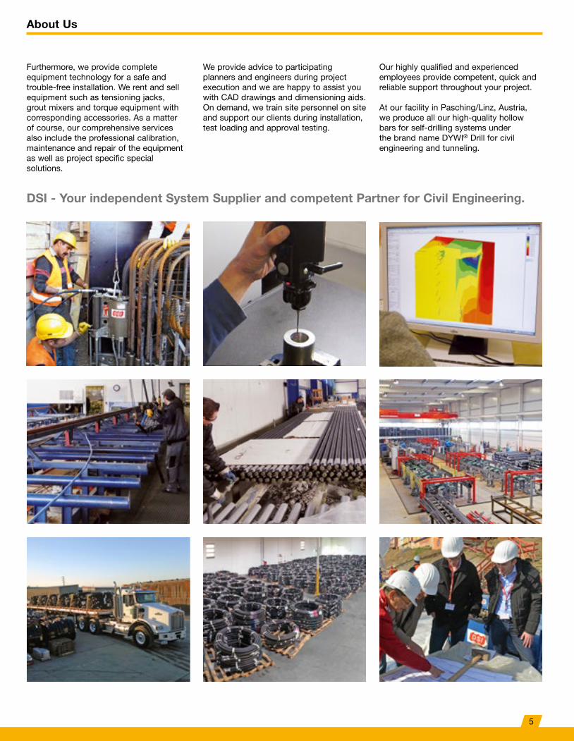
DSI - Your independent System Supplier and competent Partner for Civil Engineering.
Furthermore, we provide complete equipment technology for a safe and trouble-free installation. We rent and sell equipment such as tensioning jacks, grout mixers and torque equipment with corresponding accessories. As a matter of course, our comprehensive services also include the professional calibration, maintenance and repair of the equipment as well as project specific special solutions.
We provide advice to participating planners and engineers during project execution and we are happy to assist you with CAD drawings and dimensioning aids. On demand, we train site personnel on site and support our clients during installation, test loading and approval testing.
Our highly qualified and experienced employees provide competent, quick and reliable support throughout your project.
At our facility in Pasching/Linz, Austria, we produce all our high-quality hollow bars for self-drilling systems under the brand name DYWI® Drill for civil engineering and tunneling.
About Us
5
Fields of Application
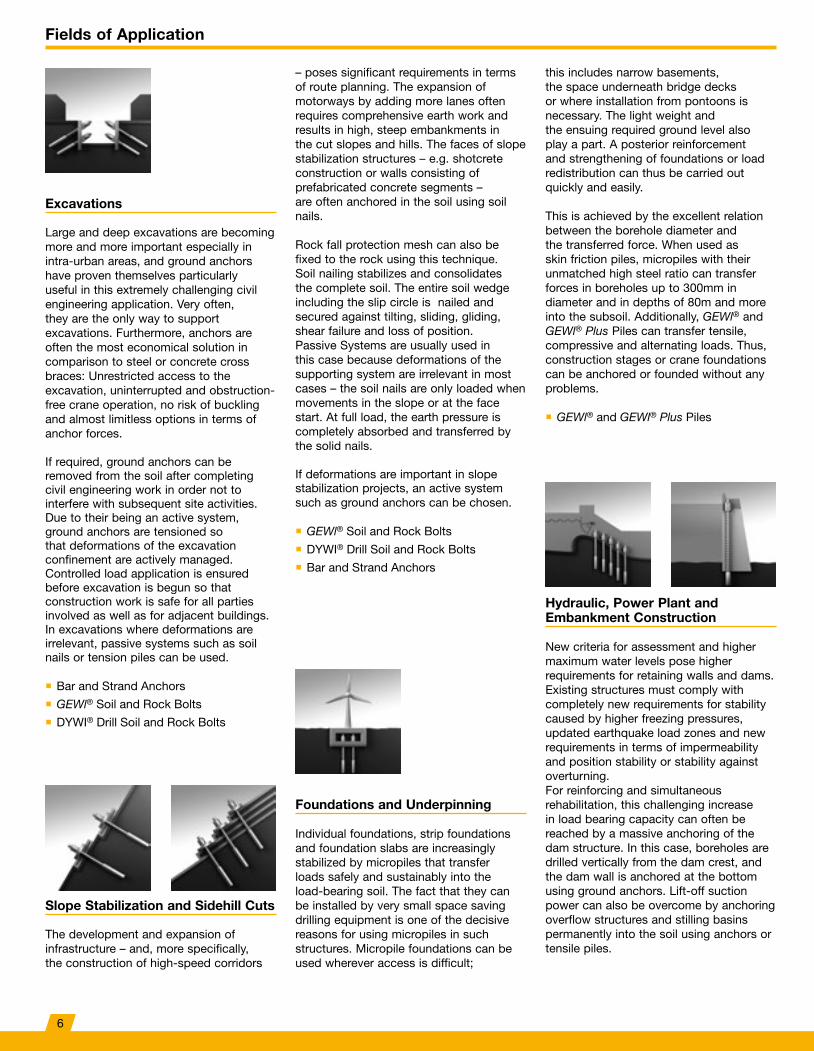
Excavations
Large and deep excavations are becoming more and more important especially in intra-urban areas, and ground anchors have proven themselves particularly useful in this extremely challenging civil engineering application. Very often, they are the only way to support excavations. Furthermore, anchors are often the most economical solution in comparison to steel or concrete cross braces: Unrestricted access to the excavation, uninterrupted and obstruction-free crane operation, no risk of buckling and almost limitless options in terms of anchor forces.
If required, ground anchors can be removed from the soil after completing civil engineering work in order not to interfere with subsequent site activities. Due to their being an active system, ground anchors are tensioned so that deformations of the excavation confinement are actively managed. Controlled load application is ensured before excavation is begun so that construction work is safe for all parties involved as well as for adjacent buildings. In excavations where deformations are irrelevant, passive systems such as soil nails or tension piles can be used.
� Bar and Strand Anchors
� GEWl® Soil and Rock Bolts
� DYWI® Drill Soil and Rock Bolts
Slope Stabilization and Sidehill Cuts
The development and expansion of infrastructure – and, more specifically, the construction of high-speed corridors
– poses significant requirements in terms of route planning. The expansion of motorways by adding more lanes often requires comprehensive earth work and results in high, steep embankments in the cut slopes and hills. The faces of slope stabilization structures – e.g. shotcrete construction or walls consisting of prefabricated concrete segments – are often anchored in the soil using soil nails.
Rock fall protection mesh can also be fixed to the rock using this technique. Soil nailing stabilizes and consolidates the complete soil. The entire soil wedge including the slip circle is nailed and secured against tilting, sliding, gliding, shear failure and loss of position. Passive Systems are usually used in this case because deformations of the supporting system are irrelevant in most cases – the soil nails are only loaded when movements in the slope or at the face start. At full load, the earth pressure is completely absorbed and transferred by the solid nails.
If deformations are important in slope stabilization projects, an active system such as ground anchors can be chosen.
� GEWl® Soil and Rock Bolts
� DYWI® Drill Soil and Rock Bolts
� Bar and Strand Anchors
Hydraulic, Power Plant and Embankment Construction
New criteria for assessment and higher maximum water levels pose higher requirements for retaining walls and dams. Existing structures must comply with completely new requirements for stability caused by higher freezing pressures, updated earthquake load zones and new requirements in terms of impermeability and position stability or stability against overturning. For reinforcing and simultaneous rehabilitation, this challenging increase in load bearing capacity can often be reached by a massive anchoring of the dam structure. In this case, boreholes are drilled vertically from the dam crest, and the dam wall is anchored at the bottom using ground anchors. Lift-off suction power can also be overcome by anchoring overflow structures and stilling basins permanently into the soil using anchors or tensile piles.
Foundations and Underpinning
Individual foundations, strip foundations and foundation slabs are increasingly stabilized by micropiles that transfer loads safely and sustainably into the load-bearing soil. The fact that they can be installed by very small space saving drilling equipment is one of the decisive reasons for using micropiles in such structures. Micropile foundations can be used wherever access is difficult;
this includes narrow basements, the space underneath bridge decks or where installation from pontoons is necessary. The light weight and the ensuing required ground level also play a part. A posterior reinforcement and strengthening of foundations or load redistribution can thus be carried out quickly and easily.
This is achieved by the excellent relation between the borehole diameter and the transferred force. When used as skin friction piles, micropiles with their unmatched high steel ratio can transfer forces in boreholes up to 300mm in diameter and in depths of 80m and more into the subsoil. Additionally, GEWl® and GEWl® Plus Piles can transfer tensile, compressive and alternating loads. Thus, construction stages or crane foundations can be anchored or founded without any problems.
� GEWl® and GEWl® Plus Piles
6
Fields of Application
Depending on water levels, different load conditions can also be safely absorbed by anchors (in case of tensile load only) or micropiles (even for alternating loads) at retaining dams.
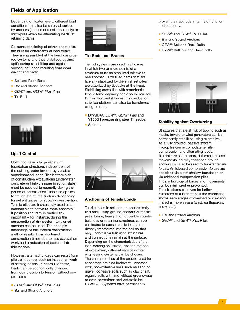
Caissons consisting of driven sheet piles are built for cofferdams or new quays. They are assembled at the head using tie rod systems and thus stabilized against uplift during sand filling and against subsequent loads resulting from dead weight and traffic.
� Soil and Rock Bolts
� Bar and Strand Anchors
� GEWl® and GEWl® Plus Piles
� Tie Rods
Tie Rods and Braces
Tie rod systems are used in all cases in which two or more points of a structure must be stabilized relative to one another. Earth filled dams that are laterally stabilized by driven sheet piles are stabilized by tiebacks at the head. Stabilizing cross ties with remarkable tensile force capacity can also be realized. Drifting horizontal forces in individual or strip foundations can also be transferred using tie rods.
� DYWIDAG GEWl®, GEWl® Plus and Y1050H prestressing steel Threadbar
� Strands
Uplift Control
Uplift occurs in a large variety of foundation structures independent of the existing water level or by variable superimposed loads. The bottom slab of construction excavations (underwater concrete or high-pressure injection slabs) must be secured temporarily during the period of construction. This also applies to trough structures such as descending tunnel entrances for subway construction. Tensile piles are increasingly used as an economic alternative to mass concrete. If position accuracy is particularly important – for instance, during the construction of dry docks – tensioned anchors can be used. The principle advantage of this system construction method results from shortened construction times due to less excavation work and a reduction of bottom slab thicknesses.
However, alternating loads can result from pile uplift control such as inspection work in settling basins. In cases like these, loads can be economically changed from compression to tension without any problems
� GEWl® and GEWl® Plus Piles
� Bar and Strand Anchors
Anchoring of Tensile Loads
Tensile loads in soil can be economically tied back using ground anchors or tensile piles. Large, heavy and noticeable counter balances or retaining structures can be eliminated because tensile loads are directly transferred into the soil so that only unobtrusive transition structures and connections remain at the surface. Depending on the characteristics of the load-bearing soil strata, and the method of excavation, different varieties of civil engineering systems can be chosen. The characteristics of the ground used for anchorage are also irrelevant - whether rock, non-cohesive soils such as sand or gravel, cohesive soils such as clay or silt, organic soils with and without groundwater or even permafrost and Antarctic ice - DYWIDAG Systems have permanently
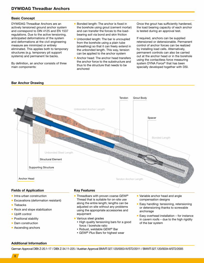
Stability against Overturning
Structures that are at risk of tipping such as masts, towers or wind generators can be permanently stabilized using micropiles. As a fully grouted, passive system, micropiles can accomodate tensile, compression and alternating loads. To minimize settlements, deformations and movements, actively tensioned ground anchors can also be used to transfer tensile forces. Anticipated compression forces are absorbed via a stiff shallow foundation or via additional compression piles. Thus, a build-up of forces and movements can be minimized or prevented. The structures can even be further reinforced at a later stage if the foundation shows early stages of overload or if exterior impact is more severe (wind, earthquakes, snow, etc.).
� Bar and Strand Anchors
� GEWl® and GEWl® Plus Piles
proven their aptitude in terms of function and economy.
� GEWl® and GEWl® Plus Piles
� Bar and Strand Anchors
� GEWl® Soil and Rock Bolts
� DYWI® Drill Soil and Rock Bolts
7
DYWIDAG Threadbar Anchors
Basic Concept
Additional Information
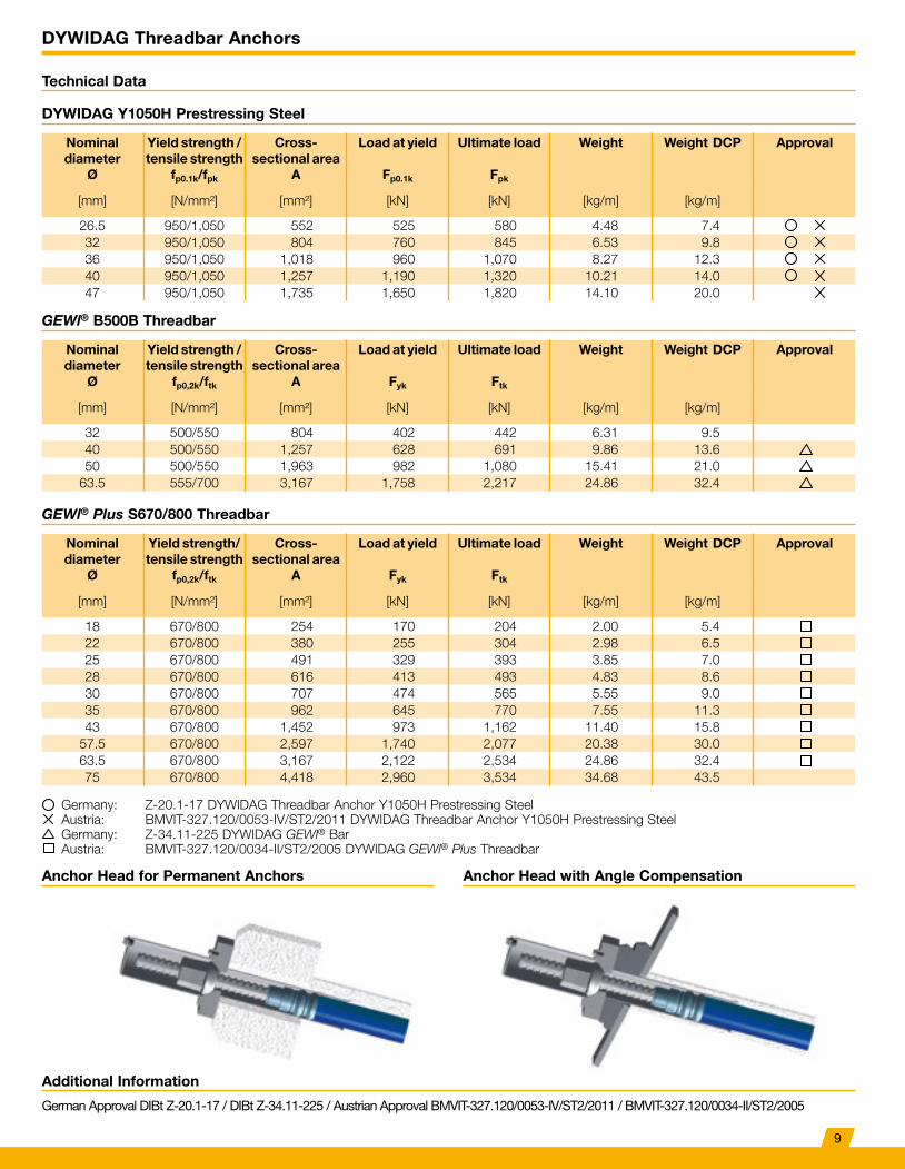
Bar Anchor Drawing
Key FeaturesFields of Application
DYWIDAG Threadbar Anchors are an actively tensioned ground anchor system and correspond to DIN 4125 and EN 1537 regulations. Due to the active tensioning, anticipated deformations of the system and deformations at the civil engineering measure are minimized or entirely eliminated. This applies both to temporary structures (e.g. temporary pit support systems) and permanent tie backs.
By definition, an anchor consists of three main components:
German Approval DIBt Z-20.1-17 / DIBt Z-34.11-225 / Austrian Approval BMVIT-327.120/0053-IV/ST2/2011 / BMVIT-327.120/0034-II/ST2/2005
Once the grout has sufficiently hardened, the load bearing capacity of each anchor is tested during an approval test.
If required, anchors can be supplied retensioned or detensionable. Permanent control of anchor forces can be realized by installing load cells. Alternatively, permanent controls can also be carried out at the anchor head or in the borehole using the contactless force measuring system DYNA Force® that has been specially developed together with DSI.
� Bonded length: The anchor is fixed in the borehole using grout (cement mortar) and can transfer the forces to the load-bearing soil via bond and skin friction
� Unbonded length: The bar is uncoupled from the borehole using a plain tube (sheathing) so that it can freely extend in the unbonded length. This way, tension can be applied to the anchor system
� Anchor head: The anchor head transfers the anchor force to the substructure and thus to the structure that needs to be anchored
� Threadbars with proven coarse GEWl® Thread that is suitable for on-site use along the entire length; lengths can be adjusted on site without any problems using the appropriate accessories and equipment
� Various steel grades High quality tensioning bars for a good force / borehole ratio Robust, weldable GEWl® Bar GEWl® Plus Bars for highest wear
� Variable anchor head and angle compensation designs
� Easy handling: tensioning, retensioning or detensioning thanks to screwable anchorage
� Easy overhead installation – for instance in cavern roofs – due to the high rigidity of the bar system
� Intra-urban construction
� Excavations (deformation resistant)
� Tiebacks
� Rock and slope stabilization
� Uplift control
� Positional stability
� Dam construction
� Ascending anchors
Supporting Structure
Anchor Head
Structural Element
Unbonded Anchor Length
Bonded Length
Unbonded Steel Length
Tendon Anchor Length
Tendon Grout Body
Spacer
8
DYWIDAG Threadbar Anchors
Technical Data
DYWIDAG Y1050H Prestressing Steel
GEWl® B500B Threadbar
GEWl® Plus S670/800 Threadbar
Additional Information
Anchor Head for Permanent Anchors Anchor Head with Angle Compensation
German Approval DIBt Z-20.1-17 / DIBt Z-34.11-225 / Austrian Approval BMVIT-327.120/0053-IV/ST2/2011 / BMVIT-327.120/0034-II/ST2/2005
Nominal diameter
Ø
Yield strength / tensile strength
fp0.1k/fpk
Cross- sectional area
A
Load at yield
Fp0.1k
Ultimate load
Fpk
Weight Weight DCP Approval
[mm] [N/mm²] [mm²] [kN] [kN] [kg/m] [kg/m]
26.5 950/1,050 552 525 580 4.48 7.432 950/1,050 804 760 845 6.53 9.836 950/1,050 1,018 960 1,070 8.27 12.340 950/1,050 1,257 1,190 1,320 10.21 14.047 950/1,050 1,735 1,650 1,820 14.10 20.0
Nominal diameter
Ø
Yield strength / tensile strength
fp0,2k/ftk
Cross- sectional area
A
Load at yield
Fyk
Ultimate load
Ftk
Weight Weight DCP Approval
[mm] [N/mm²] [mm²] [kN] [kN] [kg/m] [kg/m]
32 500/550 804 402 442 6.31 9.540 500/550 1,257 628 691 9.86 13.650 500/550 1,963 982 1,080 15.41 21.0
63.5 555/700 3,167 1,758 2,217 24.86 32.4
Nominal diameter
Ø
Yield strength/tensile strength
fp0,2k/ftk
Cross- sectional area
A
Load at yield
Fyk
Ultimate load
Ftk
Weight Weight DCP Approval
[mm] [N/mm²] [mm²] [kN] [kN] [kg/m] [kg/m]
18 670/800 254 170 204 2.00 5.422 670/800 380 255 304 2.98 6.525 670/800 491 329 393 3.85 7.028 670/800 616 413 493 4.83 8.630 670/800 707 474 565 5.55 9.035 670/800 962 645 770 7.55 11.343 670/800 1,452 973 1,162 11.40 15.8
57.5 670/800 2,597 1,740 2,077 20.38 30.063.5 670/800 3,167 2,122 2,534 24.86 32.475 670/800 4,418 2,960 3,534 34.68 43.5
Germany: Z-20.1-17 DYWIDAG Threadbar Anchor Y1050H Prestressing SteelAustria: BMVIT-327.120/0053-IV/ST2/2011 DYWIDAG Threadbar Anchor Y1050H Prestressing SteelGermany: Z-34.11-225 DYWIDAG GEWl® BarAustria: BMVIT-327.120/0034-II/ST2/2005 DYWIDAG GEWl® Plus Threadbar
9
DYWIDAG Threadbar Anchors
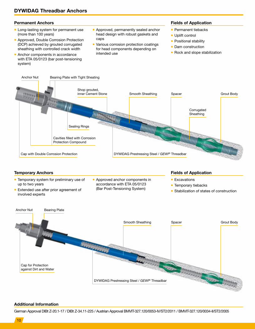
Permanent Anchors
Temporary Anchors
Fields of Application
Fields of Application
� Long-lasting system for permanent use (more than 100 years)
� Approved, Double Corrosion Protection (DCP) achieved by grouted corrugated sheathing with controlled crack width
� Anchor components in accordance with ETA 05/0123 (bar post-tensioning system)
� Temporary system for preliminary use of up to two years
� Extended use after prior agreement of involved experts
� Permanent tiebacks
� Uplift control
� Positional stability
� Dam construction
� Rock and slope stabilization
� Excavations
� Temporary tiebacks
� Stabilization of states of construction
� Approved, permanently sealed anchor head design with robust gaskets and caps
� Various corrosion protection coatings for head components depending on intended use
� Approved anchor components in accordance with ETA 05/0123 (Bar Post-Tensioning System)
Cap with Double Corrosion Protection
Bearing Plate with Tight Sheating
Bearing Plate
Smooth Sheathing
Corrugated Sheathing
Spacer Grout Body
Anchor Nut
Anchor Nut
Smooth Sheathing Spacer Grout Body
Cavities filled with Corrosion Protection Compound
Cap for Protection against Dirt and Water
Sealing Rings
DYWIDAG Prestressing Steel / GEWl® Threadbar
DYWIDAG Prestressing Steel / GEWl® Threadbar
Additional Information
German Approval DIBt Z-20.1-17 / DIBt Z-34.11-225 / Austrian Approval BMVIT-327.120/0053-IV/ST2/2011 / BMVIT-327.120/0034-II/ST2/2005
Shop grouted, inner Cement Stone
10
DYWIDAG Threadbar Anchors
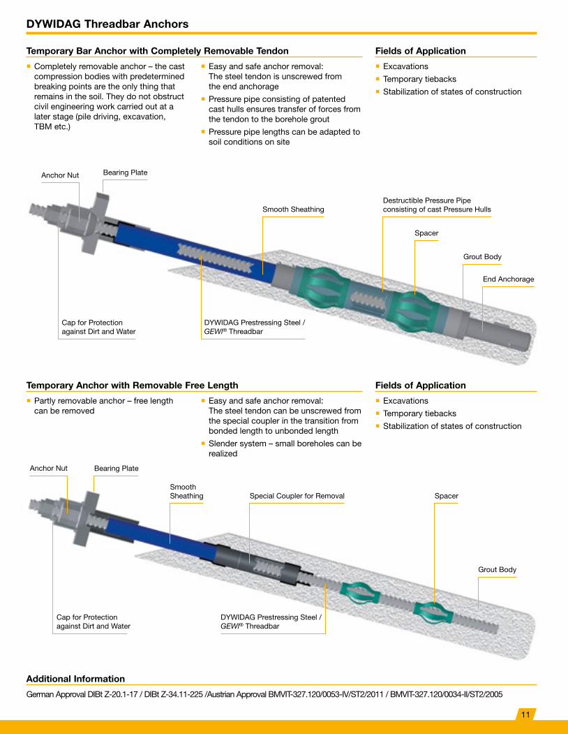
Temporary Bar Anchor with Completely Removable Tendon
Temporary Anchor with Removable Free Length
Fields of Application
Fields of Application
� Completely removable anchor – the cast compression bodies with predetermined breaking points are the only thing that remains in the soil. They do not obstruct civil engineering work carried out at a later stage (pile driving, excavation, TBM etc.)
� Partly removable anchor – free length can be removed
� Excavations
� Temporary tiebacks
� Stabilization of states of construction
� Excavations
� Temporary tiebacks
� Stabilization of states of construction
� Easy and safe anchor removal: The steel tendon is unscrewed from the end anchorage
� Pressure pipe consisting of patented cast hulls ensures transfer of forces from the tendon to the borehole grout
� Pressure pipe lengths can be adapted to soil conditions on site
� Easy and safe anchor removal: The steel tendon can be unscrewed from the special coupler in the transition from bonded length to unbonded length
� Slender system – small boreholes can be realized
Anchor Nut
Bearing Plate
Bearing Plate
Smooth SheathingDestructible Pressure Pipe consisting of cast Pressure Hulls
Spacer
End Anchorage
Grout Body
Grout Body
Anchor Nut
Smooth Sheathing Special Coupler for Removal Spacer
Cap for Protection against Dirt and Water
Cap for Protection against Dirt and Water
DYWIDAG Prestressing Steel / GEWl® Threadbar
DYWIDAG Prestressing Steel / GEWl® Threadbar
Additional Information
German Approval DIBt Z-20.1-17 / DIBt Z-34.11-225 /Austrian Approval BMVIT-327.120/0053-IV/ST2/2011 / BMVIT-327.120/0034-II/ST2/2005
11
References DYWIDAG Threadbar Anchors
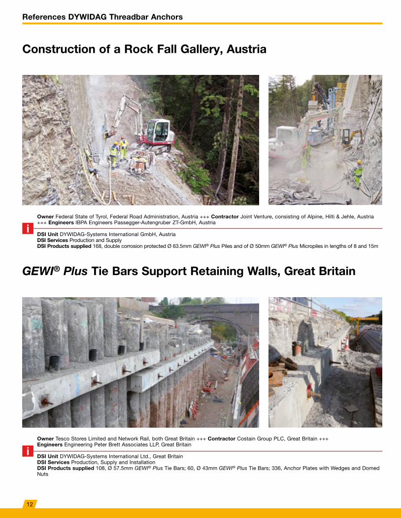
Construction of a Rock Fall Gallery, Austria
GEWI® Plus Tie Bars Support Retaining Walls, Great Britain
Owner Federal State of Tyrol, Federal Road Administration, Austria +++ Contractor Joint Venture, consisting of Alpine, Hilti & Jehle, Austria +++ Engineers IBPA Engineers Passegger-Autengruber ZT-GmbH, Austria
DSI Unit DYWIDAG-Systems International GmbH, AustriaDSI Services Production and SupplyDSI Products supplied 168, double corrosion protected Ø 63.5mm GEWI® Plus Piles and of Ø 50mm GEWI® Plus Micropiles in lengths of 8 and 15m
Owner Tesco Stores Limited and Network Rail, both Great Britain +++ Contractor Costain Group PLC, Great Britain +++Engineers Engineering Peter Brett Associates LLP, Great Britain
DSI Unit DYWIDAG-Systems International Ltd., Great BritainDSI Services Production, Supply and InstallationDSI Products supplied 108, Ø 57.5mm GEWI® Plus Tie Bars; 60, Ø 43mm GEWI® Plus Tie Bars; 336, Anchor Plates with Wedges and Domed Nuts
12
References DYWIDAG Threadbar Anchors
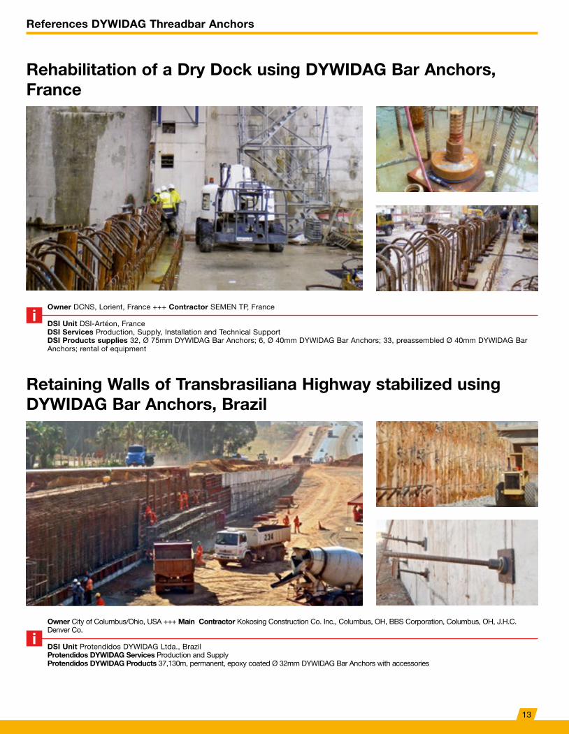
Retaining Walls of Transbrasiliana Highway stabilized using DYWIDAG Bar Anchors, Brazil
Owner City of Columbus/Ohio, USA +++ Main Contractor Kokosing Construction Co. Inc., Columbus, OH, BBS Corporation, Columbus, OH, J.H.C. Denver Co.
DSI Unit Protendidos DYWIDAG Ltda., BrazilProtendidos DYWIDAG Services Production and Supply Protendidos DYWIDAG Products 37,130m, permanent, epoxy coated Ø 32mm DYWIDAG Bar Anchors with accessories
Rehabilitation of a Dry Dock using DYWIDAG Bar Anchors, France
Owner DCNS, Lorient, France +++ Contractor SEMEN TP, France
DSI Unit DSI-Artéon, FranceDSI Services Production, Supply, Installation and Technical SupportDSI Products supplies 32, Ø 75mm DYWIDAG Bar Anchors; 6, Ø 40mm DYWIDAG Bar Anchors; 33, preassembled Ø 40mm DYWIDAG Bar Anchors; rental of equipment
13
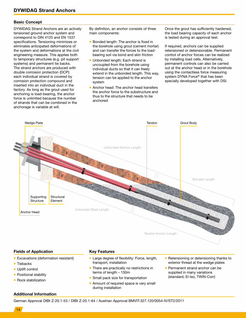
DYWIDAG Strand Anchors
Basic Concept
DYWIDAG Strand Anchors are an actively tensioned ground anchor system and correspond to DIN 4125 and EN 1537 specifications. Tensioning minimizes or eliminates anticipated deformations of the system and deformations at the civil engineering measure. This applies both to temporary structures (e.g. pit support systems) and permanent tie backs. The strand anchors are produced with double corrosion protection (DCP): each individual strand is covered by corrosion protection compound and inserted into an individual duct in the factory. As long as the grout used for anchoring is load-bearing, the anchor force is unlimited because the number of strands that can be combined in the anchorage is variable at will.
Once the grout has sufficiently hardened, the load bearing capacity of each anchor is tested during an approval test.
If required, anchors can be supplied retensioned or detensionable. Permanent control of anchor forces can be realized by installing load cells. Alternatively, permanent controls can also be carried out at the anchor head or in the borehole using the contactless force measuring system DYNA Force® that has been specially developed together with DSI.
By definition, an anchor consists of three main components:
� Bonded length: The anchor is fixed in the borehole using grout (cement mortar) and can transfer the forces to the load-bearing soil via bond and skin friction
� Unbonded length: Each strand is uncoupled from the borehole using individual ducts so that it can freely extend in the unbonded length. This way, tension can be applied to the anchor system
� Anchor head: The anchor head transfers the anchor force to the substructure and thus to the structure that needs to be anchored
Key FeaturesFields of Application
� Large degree of flexibility: Force, length, transport, installation
� There are practically no restrictions in terms of length – 150m
� Small pack size for transportation
� Amount of required space is very small during installation
� Retensioning or detensioning thanks to exterior thread at the wedge plates
� Permanent strand anchor can be supplied in many variations (standard, El-Iso, TWIN-Corr)
� Excavations (deformation resistant)
� Tiebacks
� Uplift control
� Positional stability
� Rock stabilization
Wedge Plate Tendon Grout Body
Structural Element
Anchor Head
Unbonded Anchor Length
Bonded Length
Unbonded Steel Length
Tendon Anchor Length
Supporting Structure
Additional Information
German Approval DIBt Z-20.1-53 / DIBt Z-20.1-64 / Austrian Approval BMVIT-327.120/0054-IV/ST2/2011
14
DYWIDAG Strand Anchors
Technical Data
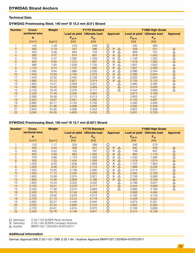
DYWIDAG Prestressing Steel, 140 mm² Ø 15.3 mm (0.6") Strand
DYWIDAG Prestressing Steel, 150 mm² Ø 15.7 mm (0.62") Strand
Number Cross- sectional area
Weight Y1770 Standard Y1860 High GradeLoad at yield Ultimate load Approval Load at yield Ultimate load Approval
A Fp0,1k Fpk Fp0,1k Fpk
[mm²] [kg/m] [kN] [kN] [kN] [kN]1 140 1.09 218 248 230 2602 280 2.19 437 496 459 5213 420 3.28 655 743 689 7814 560 4.37 874 991 918 1,0425 700 5.47 1,092 1,239 1,148 1,3026 840 6.56 1,310 1,487 1,378 1,5627 980 7.65 1,529 1,735 1,607 1,8238 1,120 8.74 1,747 1,982 1,837 2,0839 1,260 9.84 1,966 2,230 2,066 2,344
10 1,400 10.93 2,184 2,478 2,296 2,60411 1,540 12.02 2,402 2,726 2,526 2,86412 1,680 13.12 2,621 2,974 2,755 3,12513 1,820 14.21 2,839 3,221 2,985 3,38514 1,960 15.30 3,058 3,469 3,214 3,64615 2,100 16.40 3,276 3,717 3,444 3,90616 2,240 17.49 3,494 3,965 3,674 4,16617 2,380 18.58 3,713 4,213 3,903 4,42718 2,520 19.67 3,931 4,460 4,133 4,68719 2,660 20.77 4,150 4,708 4,362 4,94820 2,800 21.86 4,368 4,956 4,592 5,20821 2,940 22.95 4,586 5,204 4,822 5,46822 3,080 24.05 4,805 5,452 5,051 5,729
Number Cross- sectional area
Weight Y1770 Standard Y1860 High GradeLoad at yield Ultimate load Approval Load at yield Ultimate load Approval
A Fp0,1k Fpk Fp0,1k Fpk
[mm²] [kg/m] [kN] [kN] [kN] [kN]1 150 1.17 234 266 246 2792 300 2.34 468 531 492 5583 450 3.52 702 797 738 8374 600 4.69 963 1,062 984 1,1165 750 5.86 1,170 1,328 1,230 1,3956 900 7.03 1,404 1,593 1,476 1,6747 1,050 8.20 1,638 1,859 1,722 1,9538 1,200 9.38 1,872 2,124 1,968 2,2329 1,350 10.55 2,106 2,390 2,214 2,511
10 1,500 11.72 2,340 2,655 2,460 2,79011 1,650 12.89 2,574 2,921 2,706 3,06912 1,800 14.06 2,808 3,186 2,952 3,34813 1,950 15.24 3,042 3,452 3,198 3,62714 2,100 16.41 3,276 3,717 3,444 3,90615 2,250 17.58 3,510 3,983 3,690 4,18516 2,400 18.75 3,744 4,248 3,936 4,46417 2,550 19.92 3,978 4,514 4,182 4,74318 2,700 21.10 4,212 4,779 4,428 5,02219 2,850 22.27 4,446 5,045 4,674 5,30120 3,000 23.44 4,680 5,310 4,920 5,58021 3,150 24.61 4,914 5,576 5,166 5,85922 3,300 25.78 5,148 5,841 5,412 6,138
Germany: Z-20.1-53 SUSPA Rock AnchorsGermany: Z-20.1-64 SUSPA Compact AnchorsAustria: BMVIT-327.120/0054-IV/ST2/2011
Additional Information
German Approval DIBt Z-20.1-53 / DIBt Z-20.1-64 / Austrian Approval BMVIT-327.120/0054-IV/ST2/2011
15
DYWIDAG Strand Anchors
Fields of Application
Fields of Application
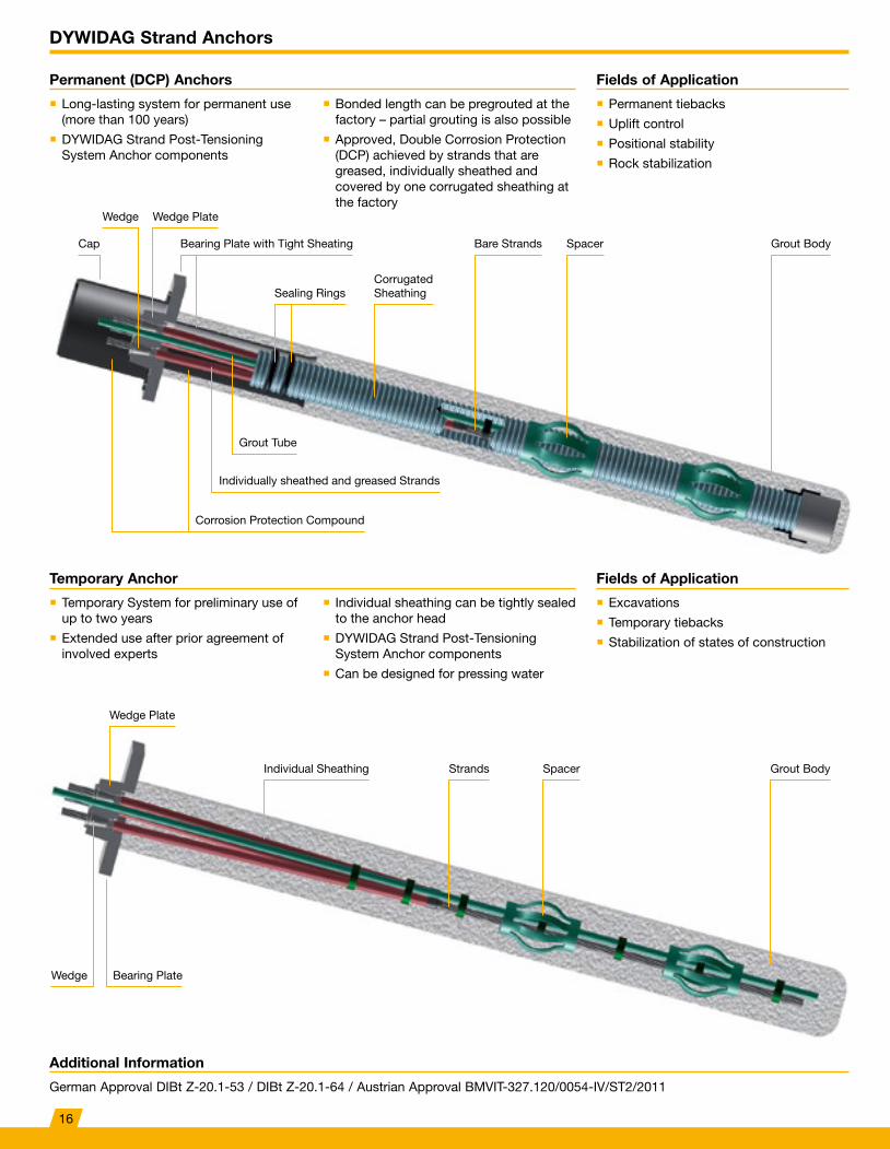
Permanent (DCP) Anchors
Temporary Anchor
� Permanent tiebacks
� Uplift control
� Positional stability
� Rock stabilization
� Excavations
� Temporary tiebacks
� Stabilization of states of construction
� Long-lasting system for permanent use (more than 100 years)
� DYWIDAG Strand Post-Tensioning System Anchor components
� Temporary System for preliminary use of up to two years
� Extended use after prior agreement of involved experts
� Bonded length can be pregrouted at the factory – partial grouting is also possible
� Approved, Double Corrosion Protection (DCP) achieved by strands that are greased, individually sheathed and covered by one corrugated sheathing at the factory
� Individual sheathing can be tightly sealed to the anchor head
� DYWIDAG Strand Post-Tensioning System Anchor components
� Can be designed for pressing water
Cap
Wedge Plate
Individual Sheathing Spacer Grout BodyStrands
Wedge Plate
Bearing Plate with Tight Sheating Bare Strands Spacer Grout Body
Corrugated SheathingSealing Rings
Corrosion Protection Compound
Wedge Bearing Plate
Individually sheathed and greased Strands
Grout Tube
Additional Information
German Approval DIBt Z-20.1-53 / DIBt Z-20.1-64 / Austrian Approval BMVIT-327.120/0054-IV/ST2/2011
Wedge
16
DYWIDAG Strand Anchors
Fields of Application
Fields of Application
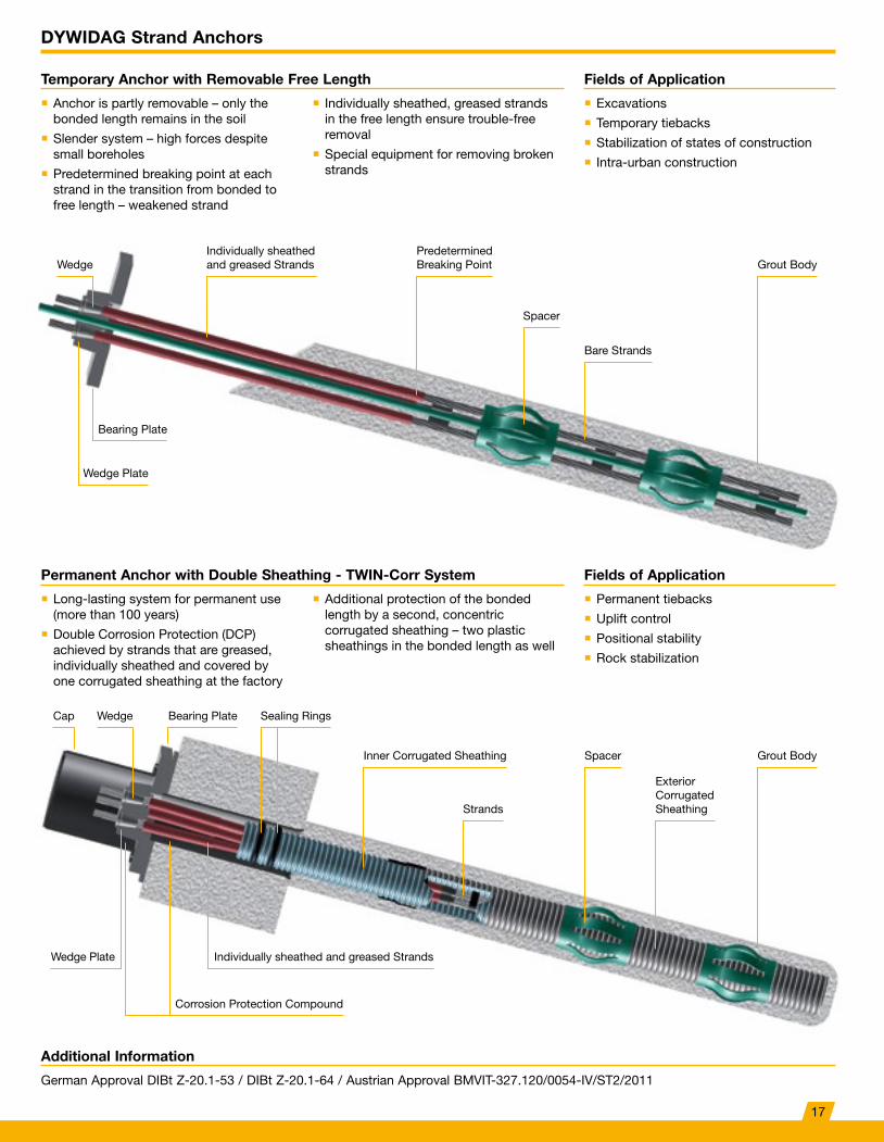
Temporary Anchor with Removable Free Length
Permanent Anchor with Double Sheathing - TWIN-Corr System
� Excavations
� Temporary tiebacks
� Stabilization of states of construction
� Intra-urban construction
� Permanent tiebacks
� Uplift control
� Positional stability
� Rock stabilization
� Anchor is partly removable – only the bonded length remains in the soil
� Slender system – high forces despite small boreholes
� Predetermined breaking point at each strand in the transition from bonded to free length – weakened strand
� Long-lasting system for permanent use (more than 100 years)
� Double Corrosion Protection (DCP) achieved by strands that are greased, individually sheathed and covered by one corrugated sheathing at the factory
� Individually sheathed, greased strands in the free length ensure trouble-free removal
� Special equipment for removing broken strands
� Additional protection of the bonded length by a second, concentric corrugated sheathing – two plastic sheathings in the bonded length as well
Wedge Plate
Wedge Plate
Corrosion Protection Compound
Inner Corrugated Sheathing Spacer Grout Body
Strands
Exterior CorrugatedSheathing
Bearing Plate
Bearing Plate
Wedge
WedgeCap
Individually sheathed and greased Strands
Predetermined Breaking Point Grout Body
Sealing Rings
Spacer
Bare Strands
Individually sheathed and greased Strands
Additional Information
German Approval DIBt Z-20.1-53 / DIBt Z-20.1-64 / Austrian Approval BMVIT-327.120/0054-IV/ST2/2011
17
DYWIDAG Strand Anchors
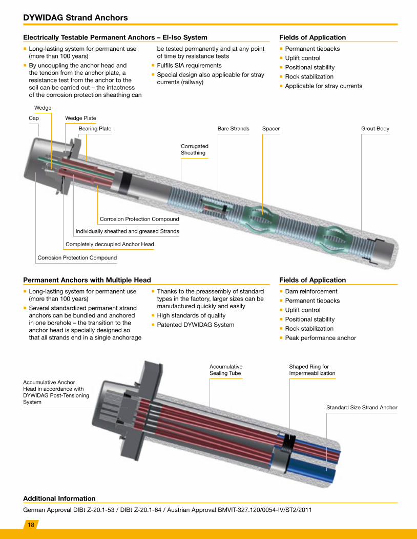
Fields of ApplicationElectrically Testable Permanent Anchors – El-Iso System
� Permanent tiebacks
� Uplift control
� Positional stability
� Rock stabilization
� Applicable for stray currents
� Long-lasting system for permanent use (more than 100 years)
� By uncoupling the anchor head and the tendon from the anchor plate, a resistance test from the anchor to the soil can be carried out – the intactness of the corrosion protection sheathing can
be tested permanently and at any point of time by resistance tests
� Fulfils SIA requirements
� Special design also applicable for stray currents (railway)
Fields of ApplicationPermanent Anchors with Multiple Head
� Dam reinforcement
� Permanent tiebacks
� Uplift control
� Positional stability
� Rock stabilization
� Peak performance anchor
� Long-lasting system for permanent use (more than 100 years)
� Several standardized permanent strand anchors can be bundled and anchored in one borehole – the transition to the anchor head is specially designed so that all strands end in a single anchorage
� Thanks to the preassembly of standard types in the factory, larger sizes can be manufactured quickly and easily
� High standards of quality
� Patented DYWIDAG System
Cap Wedge Plate
Bearing Plate Bare Strands Spacer
Accumulative Sealing Tube
Shaped Ring for Impermeabilization
Standard Size Strand Anchor
Grout Body
Corrugated Sheathing
Corrosion Protection Compound
Corrosion Protection Compound
Completely decoupled Anchor Head
Accumulative Anchor Head in accordance with DYWIDAG Post-Tensioning System
Individually sheathed and greased Strands
Additional Information
German Approval DIBt Z-20.1-53 / DIBt Z-20.1-64 / Austrian Approval BMVIT-327.120/0054-IV/ST2/2011
Wedge
18
References DYWIDAG Strand Anchors
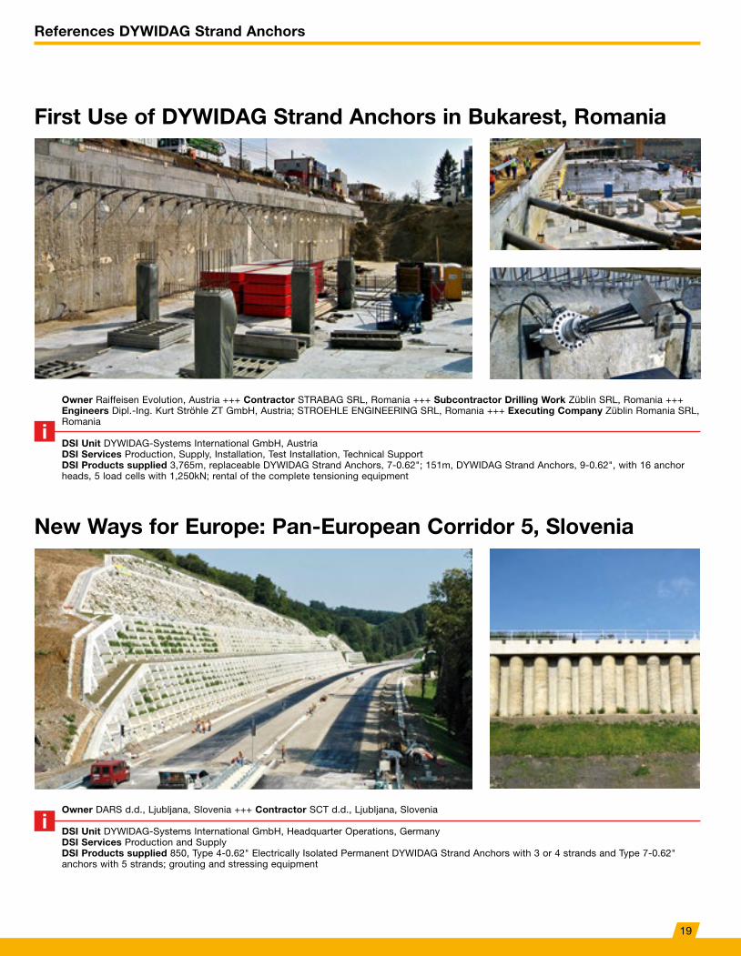
First Use of DYWIDAG Strand Anchors in Bukarest, Romania
New Ways for Europe: Pan-European Corridor 5, Slovenia
Owner Raiffeisen Evolution, Austria +++ Contractor STRABAG SRL, Romania +++ Subcontractor Drilling Work Züblin SRL, Romania +++ Engineers Dipl.-Ing. Kurt Ströhle ZT GmbH, Austria; STROEHLE ENGINEERING SRL, Romania +++ Executing Company Züblin Romania SRL, Romania
DSI Unit DYWIDAG-Systems International GmbH, AustriaDSI Services Production, Supply, Installation, Test Installation, Technical Support DSI Products supplied 3,765m, replaceable DYWIDAG Strand Anchors, 7-0.62"; 151m, DYWIDAG Strand Anchors, 9-0.62", with 16 anchor heads, 5 load cells with 1,250kN; rental of the complete tensioning equipment
Owner DARS d.d., Ljubljana, Slovenia +++ Contractor SCT d.d., Ljubljana, Slovenia
DSI Unit DYWIDAG-Systems International GmbH, Headquarter Operations, GermanyDSI Services Production and SupplyDSI Products supplied 850, Type 4-0.62" Electrically Isolated Permanent DYWIDAG Strand Anchors with 3 or 4 strands and Type 7-0.62" anchors with 5 strands; grouting and stressing equipment
19
References DYWIDAG Strand Anchors
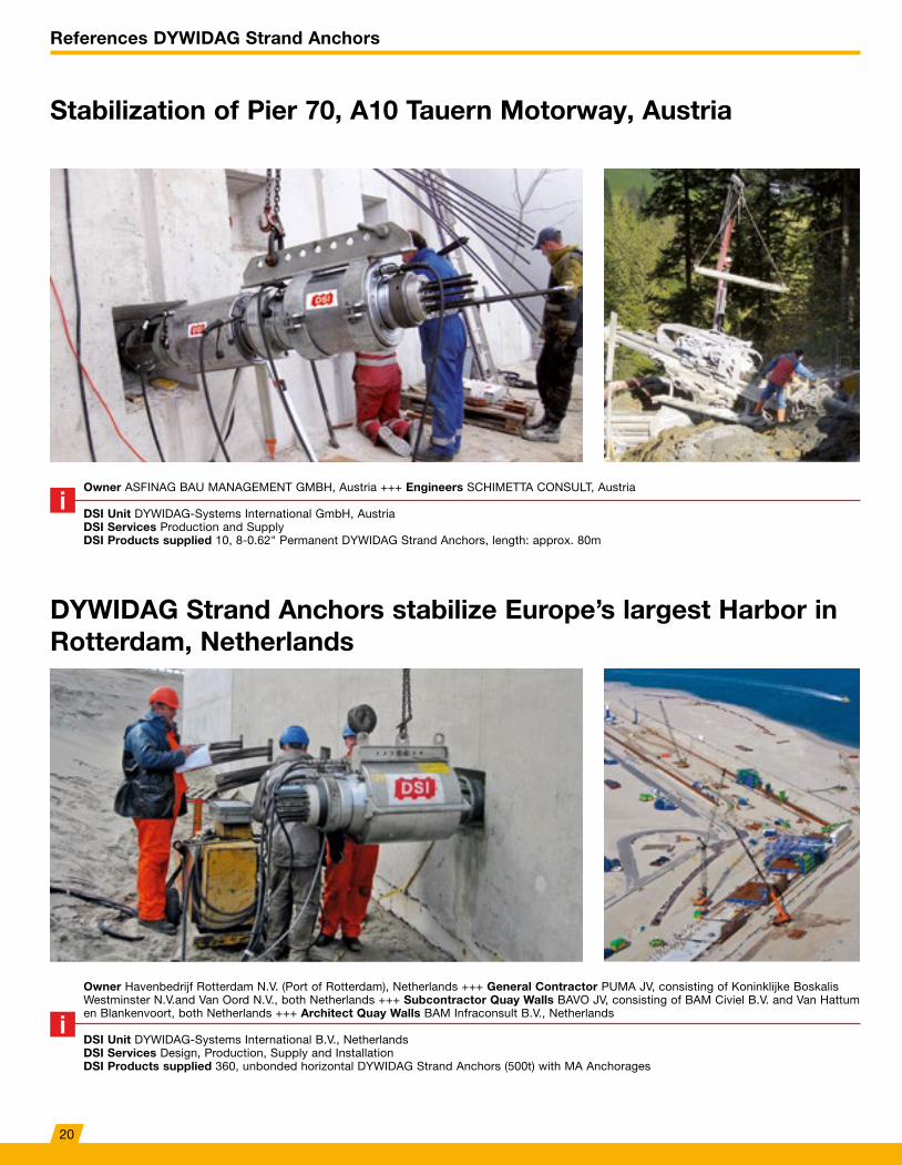
DYWIDAG Strand Anchors stabilize Europe’s largest Harbor in Rotterdam, Netherlands
Owner Havenbedrijf Rotterdam N.V. (Port of Rotterdam), Netherlands +++ General Contractor PUMA JV, consisting of Koninklijke Boskalis Westminster N.V.and Van Oord N.V., both Netherlands +++ Subcontractor Quay Walls BAVO JV, consisting of BAM Civiel B.V. and Van Hattum en Blankenvoort, both Netherlands +++ Architect Quay Walls BAM Infraconsult B.V., Netherlands
DSI Unit DYWIDAG-Systems International B.V., NetherlandsDSI Services Design, Production, Supply and InstallationDSI Products supplied 360, unbonded horizontal DYWIDAG Strand Anchors (500t) with MA Anchorages
Stabilization of Pier 70, A10 Tauern Motorway, Austria
Owner ASFINAG BAU MANAGEMENT GMBH, Austria +++ Engineers SCHIMETTA CONSULT, Austria
DSI Unit DYWIDAG-Systems International GmbH, AustriaDSI Services Production and SupplyDSI Products supplied 10, 8-0.62" Permanent DYWIDAG Strand Anchors, length: approx. 80m
20
References DYWIDAG Strand Anchors
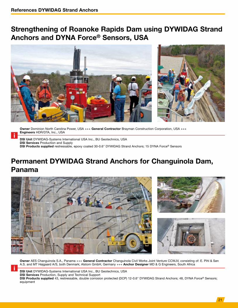
Strengthening of Roanoke Rapids Dam using DYWIDAG Strand Anchors and DYNA Force® Sensors, USA
Permanent DYWIDAG Strand Anchors for Changuinola Dam, Panama
Owner Dominion North Carolina Power, USA +++ General Contractor Brayman Construction Corporation, USA +++ Engineers HDR/DTA, Inc., USA
DSI Unit DYWIDAG-Systems International USA Inc., BU Geotechnics, USADSI Services Production and SupplyDSI Products supplied restressable, epoxy coated 30-0.6" DYWIDAG Strand Anchors; 15 DYNA Force® Sensors
Owner AES Changuinola S.A., Panama +++ General Contractor Changuinola Civil Works Joint Venture CCWJV, consisting of: E. Pihl & Søn A.S. and MT Højgaard A/S, both Denmark; Alstom GmbH, Germany +++ Anchor Designer MD & G Engineers, South Africa
DSI Unit DYWIDAG-Systems International USA Inc., BU Geotechnics, USADSI Services Production, Supply and Technical SupportDSI Products supplied 43, restressable, double corrosion protected (DCP) 12-0.6" DYWIDAG Strand Anchors; 48, DYNA Force® Sensors; equipment
21
GEWl® Pile System
Basic Concept
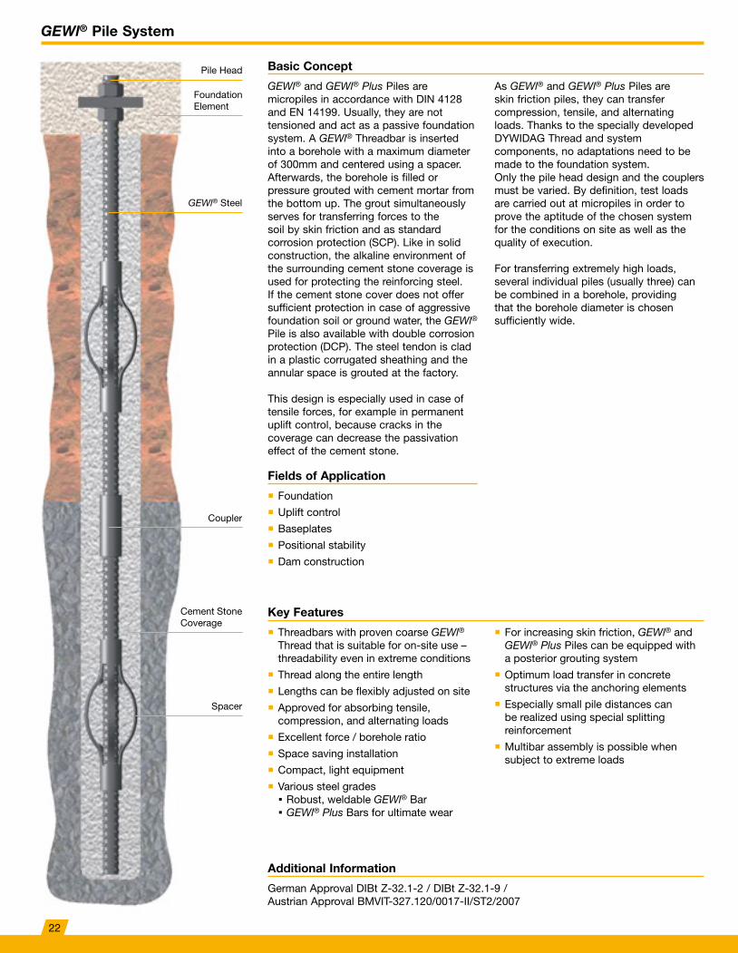
GEWl® and GEWl® Plus Piles are micropiles in accordance with DIN 4128 and EN 14199. Usually, they are not tensioned and act as a passive foundation system. A GEWl® Threadbar is inserted into a borehole with a maximum diameter of 300mm and centered using a spacer. Afterwards, the borehole is filled or pressure grouted with cement mortar from the bottom up. The grout simultaneously serves for transferring forces to the soil by skin friction and as standard corrosion protection (SCP). Like in solid construction, the alkaline environment of the surrounding cement stone coverage is used for protecting the reinforcing steel. If the cement stone cover does not offer sufficient protection in case of aggressive foundation soil or ground water, the GEWl® Pile is also available with double corrosion protection (DCP). The steel tendon is clad in a plastic corrugated sheathing and the annular space is grouted at the factory.
This design is especially used in case of tensile forces, for example in permanent uplift control, because cracks in the coverage can decrease the passivation effect of the cement stone.
As GEWl® and GEWl® Plus Piles are skin friction piles, they can transfer compression, tensile, and alternating loads. Thanks to the specially developed DYWIDAG Thread and system components, no adaptations need to be made to the foundation system. Only the pile head design and the couplers must be varied. By definition, test loads are carried out at micropiles in order to prove the aptitude of the chosen system for the conditions on site as well as the quality of execution.
For transferring extremely high loads, several individual piles (usually three) can be combined in a borehole, providing that the borehole diameter is chosen sufficiently wide.
Fields of Application
� Foundation
� Uplift control
� Baseplates
� Positional stability
� Dam construction
Key Features
� Threadbars with proven coarse GEWl® Thread that is suitable for on-site use – threadability even in extreme conditions
� Thread along the entire length
� Lengths can be flexibly adjusted on site
� Approved for absorbing tensile, compression, and alternating loads
� Excellent force / borehole ratio
� Space saving installation
� Compact, light equipment
� Various steel grades Robust, weldable GEWl® Bar GEWl® Plus Bars for ultimate wear
� For increasing skin friction, GEWl® and GEWl® Plus Piles can be equipped with a posterior grouting system
� Optimum load transfer in concrete structures via the anchoring elements
� Especially small pile distances can be realized using special splitting reinforcement
� Multibar assembly is possible when subject to extreme loads
Additional Information
German Approval DIBt Z-32.1-2 / DIBt Z-32.1-9 / Austrian Approval BMVIT-327.120/0017-II/ST2/2007
Pile Head
Foundation Element
Coupler
Spacer
Cement Stone Coverage
GEWl® Steel
22
GEWl® Pile System
Technical Data
Additional Information
German Approval DIBt Z-32.1-2 / DIBt Z-32.1-9 / Austrian Approval BMVIT-327.120/0017-II/ST2/2007
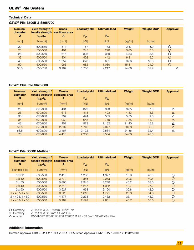
GEWl® Pile B500B & S555/700
GEWl® Pile B500B Multibar
GEWl® Plus Pile S670/800
Nominal diameter
Ø
Yield strength / tensile strength
f0,2k/ftk
Cross-sectional area
A
Load at yield
Fyk
Ultimate load
Ftk
Weight Weight DCP Approval
[mm] [N/mm²] [mm²] [kN] [kN] [kg/m] [kg/m]
20 500/550 314 157 173 2.47 5.925 500/550 491 245 270 3.85 7.028 500/550 616 308 339 4.83 8.632 500/550 804 402 442 6.31 9.540 500/550 1,257 628 691 9.86 13.650 500/550 1,963 982 1,080 15.41 21.0
63.5 555/700 3,167 1,758 2,217 24.86 32.4
Nominal diameter
Ø
Yield strength / tensile strength
f0,2k/ftk
Cross-sectional area
A
Load at yield
Fyk
Ultimate load
Ftk
Weight Weight DCP Approval
[Number x Ø] [N/mm²] [mm²] [kN] [kN] [kg/m] [kg/m]
3 x 32 500/550 2,413 1,206 1,327 18.9 28.53 x 40 500/550 3,770 1,885 2,073 29.6 40.83 x 50 500/550 5,890 2,945 3,240 46.2 63.02 x 40 500/550 2,513 1,257 1,382 19.7 27.22 x 50 500/550 3,927 1,963 2,160 30.8 42.0
1 x 40 & 1 x 50 500/550 3,220 1,610 1,771 25.3 34.62 x 40 & 1 x 50 500/550 4,477 2,238 2,462 35.1 48.21 x 40 & 2 x 50 500/550 5,184 2,592 2,851 40.7 55.6
Nominal diameter
Ø
Yield strength / tensile strength
f0,2k/ftk
Cross-sectional area
A
Load at yield
Fyk
Ultimate load
Ftk
Weight Weight DCP Approval
[mm] [N/mm²] [mm²] [kN] [kN] [kg/m] [kg/m]
25 670/800 491 329 393 3.85 7.028 670/800 616 413 493 4.83 8.630 670/800 707 474 565 5.55 9.035 670/800 962 645 770 7.55 11.343 670/800 1,452 973 1,162 11.40 15.8
57.5 670/800 2,597 1,740 2,077 20.38 30.063.5 670/800 3,167 2,122 2,534 24.86 32.475 670/800 4,418 2,960 3,534 34.68 43.5
Germany: Z-32.1-2 Ø 20 - 50mm GEWl® PileGermany: Z-32.1-9 Ø 63.5mm GEWl® PileAustria: BMVIT-327.120/0017-II/ST 2/2007 Ø 25 - 63.5mm GEWl® Plus Pile
23
GEWl® Pile System
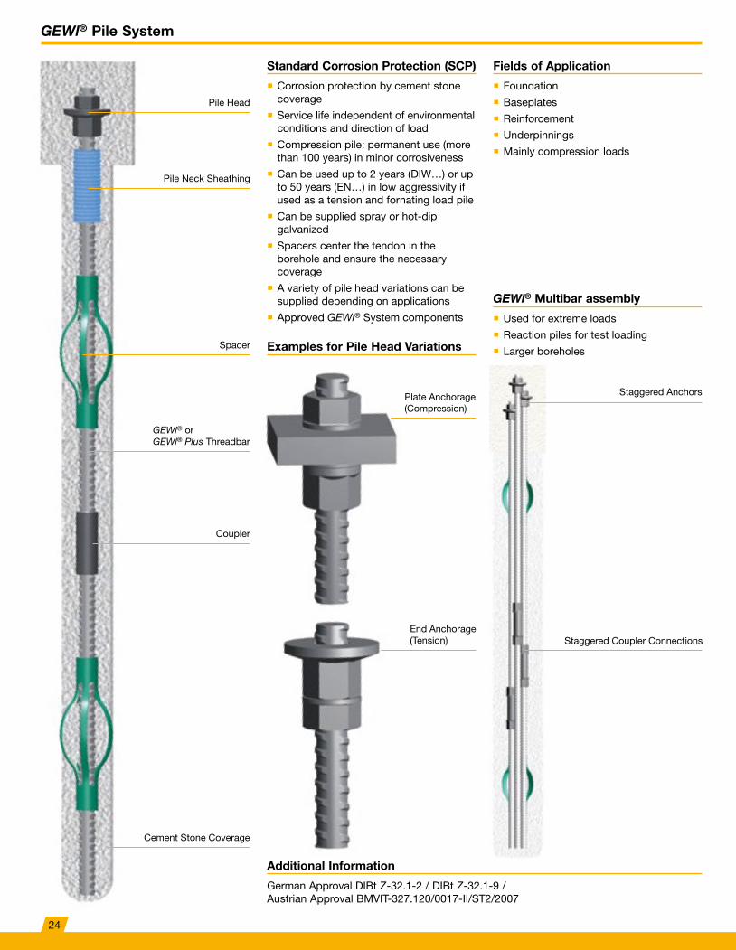
Standard Corrosion Protection (SCP)
� Corrosion protection by cement stone coverage
� Service life independent of environmental conditions and direction of load
� Compression pile: permanent use (more than 100 years) in minor corrosiveness
� Can be used up to 2 years (DIW…) or up to 50 years (EN…) in low aggressivity if used as a tension and fornating load pile
� Can be supplied spray or hot-dip galvanized
� Spacers center the tendon in the borehole and ensure the necessary coverage
� A variety of pile head variations can be supplied depending on applications
� Approved GEWl® System components
Fields of Application
GEWl® Multibar assembly
Examples for Pile Head Variations
� Foundation
� Baseplates
� Reinforcement
� Underpinnings
� Mainly compression loads
� Used for extreme loads
� Reaction piles for test loading
� Larger boreholes
Staggered AnchorsPlate Anchorage (Compression)
End Anchorage (Tension) Staggered Coupler Connections
Pile Head
Pile Neck Sheathing
Spacer
Coupler
Cement Stone Coverage
GEWl® or GEWl® Plus Threadbar
Additional Information
German Approval DIBt Z-32.1-2 / DIBt Z-32.1-9 / Austrian Approval BMVIT-327.120/0017-II/ST2/2007
24
GEWl® Pile System
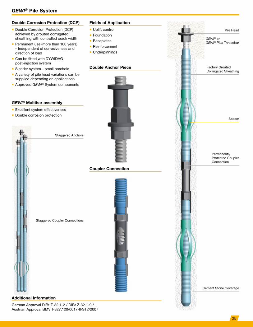
Double Corrosion Protection (DCP)
� Double Corrosion Protection (DCP) achieved by grouted corrugated sheathing with controlled crack width
� Permanent use (more than 100 years) – independent of corrosiveness and direction of load
� Can be fitted with DYWIDAG post-injection system
� Slender system – small borehole
� A variety of pile head variations can be supplied depending on applications
� Approved GEWl® System components
Fields of Application
GEWl® Multibar assembly
Coupler Connection
Double Anchor Piece
� Uplift control
� Foundation
� Baseplates
� Reinforcement
� Underpinnings
� Excellent system effectiveness
� Double corrosion protection
Staggered Anchors
Staggered Coupler Connections
Pile Head
Spacer
GEWl® or GEWl® Plus Threadbar
Factory Grouted Corrugated Sheathing
Permanently Protected Coupler Connection
Cement Stone Coverage
Additional Information
German Approval DIBt Z-32.1-2 / DIBt Z-32.1-9 / Austrian Approval BMVIT-327.120/0017-II/ST2/2007
25
References GEWl® Piles
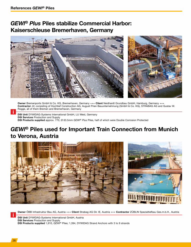
GEWl® Plus Piles stabilize Commercial Harbor: Kaiserschleuse Bremerhaven, Germany
GEWl® Piles used for Important Train Connection from Munich to Verona, Austria
Owner Bremenports GmbH & Co. KG, Bremerhaven, Germany +++ Client Neidhardt Grundbau GmbH, Hamburg, Germany +++ Contractor JV, consisting of Hochtief Construction AG, August Prien Bauunternehmung (GmbH & Co. KG), STRABAG AG and Gustav W. Rogge, all of them Bremen and Bremerhaven, Germany
DSI Unit DYWIDAG-Systems International GmbH, LU West, GermanyDSI Services Production and SupplyDSI Products supplied approx. 770, Ø 63.5mm GEWl® Plus Piles, half of which were Double Corrosion Protected
Owner ÖBB Infrastruktur Bau AG, Austria +++ Client Strabag AG Dir. IE, Austria +++ Contractor ZÜBLIN Spezialtiefbau Ges.m.b.H., Austria
DSI Unit DYWIDAG-Systems International GmbH, AustriaDSI Services Production and SupplyDSI Products supplied 1,910, GEWI® Piles; 1,394, DYWIDAG Strand Anchors with 3 to 9 strands
26
References GEWl® Piles
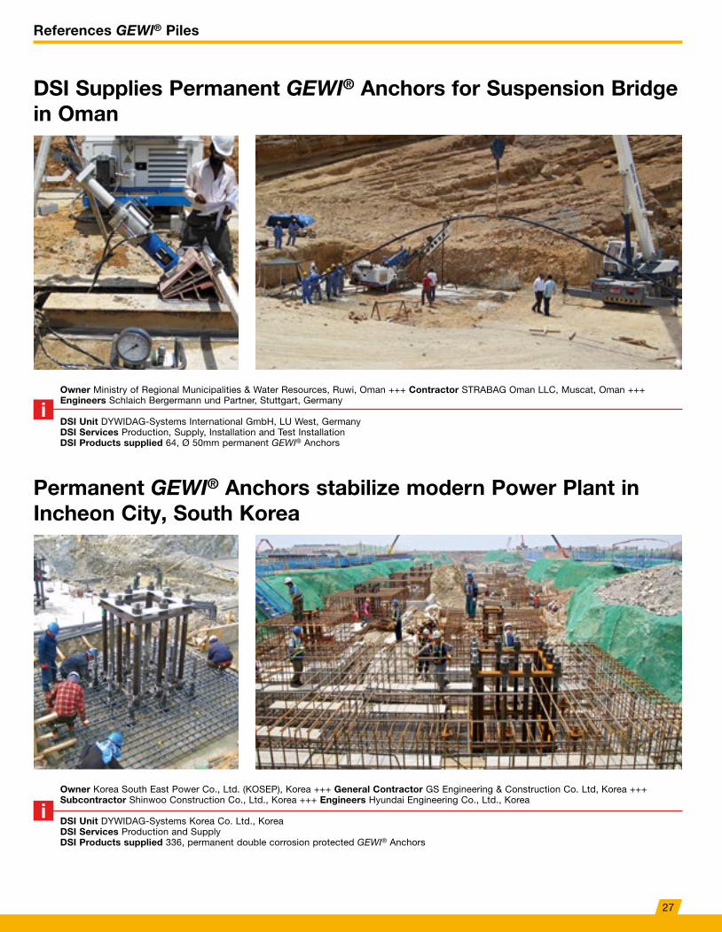
DSI Supplies Permanent GEWI® Anchors for Suspension Bridge in Oman
Permanent GEWI® Anchors stabilize modern Power Plant in Incheon City, South Korea
Owner Ministry of Regional Municipalities & Water Resources, Ruwi, Oman +++ Contractor STRABAG Oman LLC, Muscat, Oman +++ Engineers Schlaich Bergermann und Partner, Stuttgart, Germany
DSI Unit DYWIDAG-Systems International GmbH, LU West, GermanyDSI Services Production, Supply, Installation and Test InstallationDSI Products supplied 64, Ø 50mm permanent GEWI® Anchors
Owner Korea South East Power Co., Ltd. (KOSEP), Korea +++ General Contractor GS Engineering & Construction Co. Ltd, Korea +++ Subcontractor Shinwoo Construction Co., Ltd., Korea +++ Engineers Hyundai Engineering Co., Ltd., Korea
DSI Unit DYWIDAG-Systems Korea Co. Ltd., KoreaDSI Services Production and SupplyDSI Products supplied 336, permanent double corrosion protected GEWI® Anchors
27
DYWIDAG Soil Nails
Additional Information
Approval Germany DIBt Z-20.1-106 / Approval Austria BMVIT-327.120/0022-II/ST2/2006
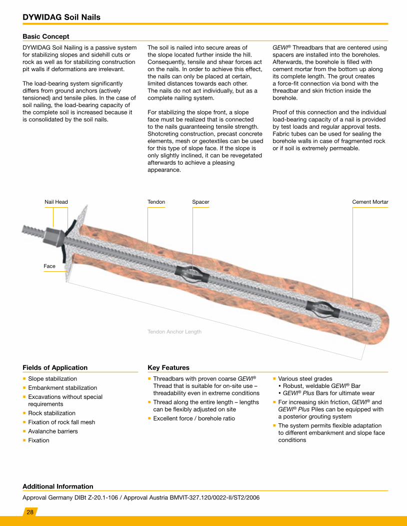
Basic Concept
DYWIDAG Soil Nailing is a passive system for stabilizing slopes and sidehill cuts or rock as well as for stabilizing construction pit walls if deformations are irrelevant.
The load-bearing system significantly differs from ground anchors (actively tensioned) and tensile piles. In the case of soil nailing, the load-bearing capacity of the complete soil is increased because it is consolidated by the soil nails.
GEWl® Threadbars that are centered using spacers are installed into the boreholes. Afterwards, the borehole is filled with cement mortar from the bottom up along its complete length. The grout creates a force-fit connection via bond with the threadbar and skin friction inside the borehole.
Proof of this connection and the individual load-bearing capacity of a nail is provided by test loads and regular approval tests. Fabric tubes can be used for sealing the borehole walls in case of fragmented rock or if soil is extremely permeable.
The soil is nailed into secure areas of the slope located further inside the hill. Consequently, tensile and shear forces act on the nails. In order to achieve this effect, the nails can only be placed at certain, limited distances towards each other. The nails do not act individually, but as a complete nailing system.
For stabilizing the slope front, a slope face must be realized that is connected to the nails guaranteeing tensile strength. Shotcreting construction, precast concrete elements, mesh or geotextiles can be used for this type of slope face. If the slope is only slightly inclined, it can be revegetated afterwards to achieve a pleasing appearance.
Tendon Anchor Length
Key FeaturesFields of Application
� Threadbars with proven coarse GEWl® Thread that is suitable for on-site use – threadability even in extreme conditions
� Thread along the entire length – lengths can be flexibly adjusted on site
� Excellent force / borehole ratio
� Various steel grades Robust, weldable GEWl® Bar GEWl® Plus Bars for ultimate wear
� For increasing skin friction, GEWl® and GEWl® Plus Piles can be equipped with a posterior grouting system
� The system permits flexible adaptation to different embankment and slope face conditions
� Slope stabilization
� Embankment stabilization
� Excavations without special requirements
� Rock stabilization
� Fixation of rock fall mesh
� Avalanche barriers
� Fixation
Nail Head
Face
Tendon Spacer Cement Mortar
28
DYWIDAG Soil Nails
Additional Information
German Approval DIBt Z-20.1-106 / Austrian Approval BMVIT-327.120/0022-II/ST2/2006
Technical Data
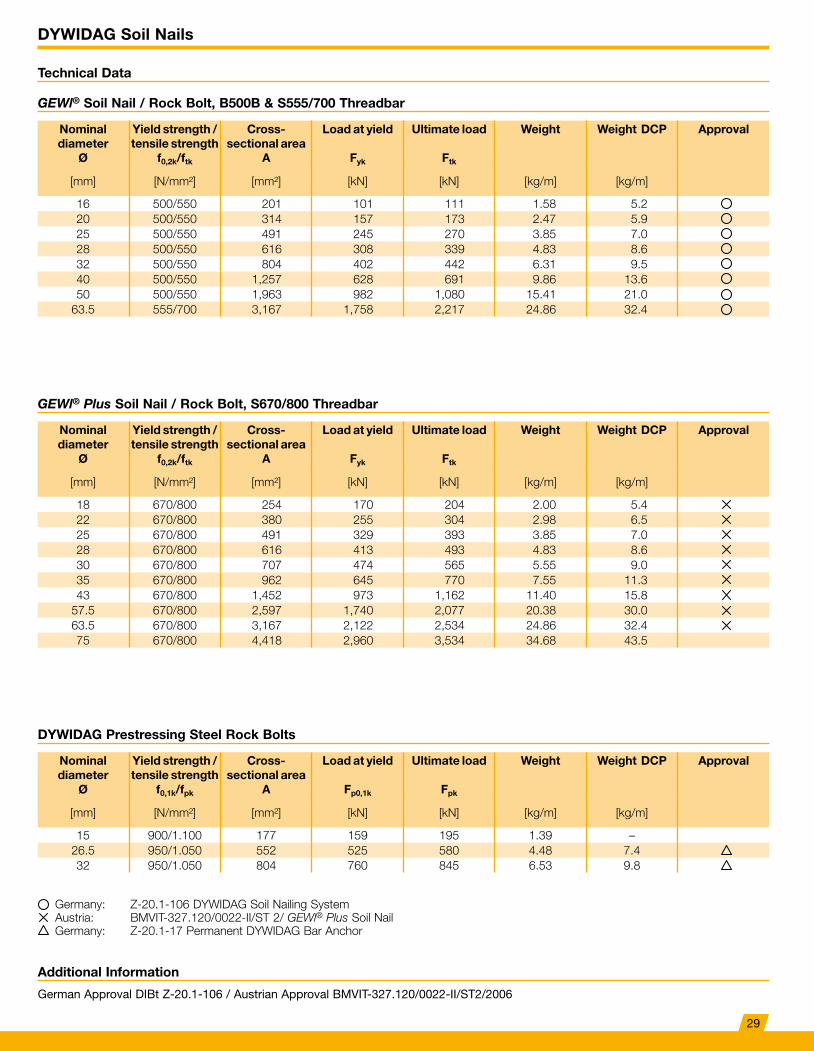
GEWl® Soil Nail / Rock Bolt, B500B & S555/700 Threadbar
Nominal diameter
Ø
Yield strength / tensile strength
f0,2k/ftk
Cross-sectional area
A
Load at yield
Fyk
Ultimate load
Ftk
Weight Weight DCP Approval
[mm] [N/mm²] [mm²] [kN] [kN] [kg/m] [kg/m]
16 500/550 201 101 111 1.58 5.220 500/550 314 157 173 2.47 5.925 500/550 491 245 270 3.85 7.028 500/550 616 308 339 4.83 8.632 500/550 804 402 442 6.31 9.540 500/550 1,257 628 691 9.86 13.650 500/550 1,963 982 1,080 15.41 21.0
63.5 555/700 3,167 1,758 2,217 24.86 32.4
GEWl® Plus Soil Nail / Rock Bolt, S670/800 Threadbar
DYWIDAG Prestressing Steel Rock Bolts
Nominal diameter
Ø
Yield strength / tensile strength
f0,2k/ftk
Cross-sectional area
A
Load at yield
Fyk
Ultimate load
Ftk
Weight Weight DCP Approval
[mm] [N/mm²] [mm²] [kN] [kN] [kg/m] [kg/m]
18 670/800 254 170 204 2.00 5.422 670/800 380 255 304 2.98 6.525 670/800 491 329 393 3.85 7.028 670/800 616 413 493 4.83 8.630 670/800 707 474 565 5.55 9.035 670/800 962 645 770 7.55 11.343 670/800 1,452 973 1,162 11.40 15.8
57.5 670/800 2,597 1,740 2,077 20.38 30.063.5 670/800 3,167 2,122 2,534 24.86 32.475 670/800 4,418 2,960 3,534 34.68 43.5
Nominal diameter
Ø
Yield strength / tensile strength
f0,1k/fpk
Cross-sectional area
A
Load at yield
Fp0,1k
Ultimate load
Fpk
Weight Weight DCP Approval
[mm] [N/mm²] [mm²] [kN] [kN] [kg/m] [kg/m]
15 900/1.100 177 159 195 1.39 –26.5 950/1.050 552 525 580 4.48 7.432 950/1.050 804 760 845 6.53 9.8
Germany: Z-20.1-106 DYWIDAG Soil Nailing SystemAustria: BMVIT-327.120/0022-II/ST 2/ GEWl® Plus Soil NailGermany: Z-20.1-17 Permanent DYWIDAG Bar Anchor
29
DYWIDAG Soil Nails
Fields of Application
Fields of Application
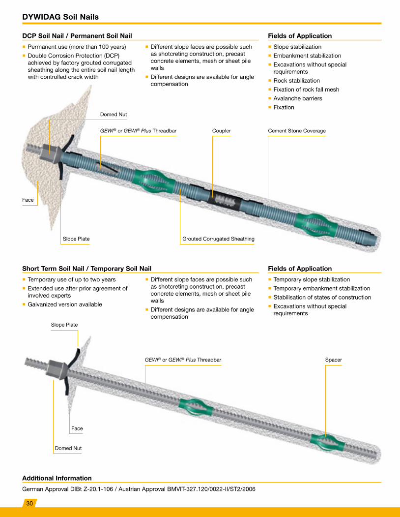
DCP Soil Nail / Permanent Soil Nail
Short Term Soil Nail / Temporary Soil Nail
� Slope stabilization
� Embankment stabilization
� Excavations without special requirements
� Rock stabilization
� Fixation of rock fall mesh
� Avalanche barriers
� Fixation
� Temporary slope stabilization
� Temporary embankment stabilization
� Stabilisation of states of construction
� Excavations without special requirements
� Permanent use (more than 100 years)
� Double Corrosion Protection (DCP) achieved by factory grouted corrugated sheathing along the entire soil nail length with controlled crack width
� Temporary use of up to two years
� Extended use after prior agreement of involved experts
� Galvanized version available
� Different slope faces are possible such as shotcreting construction, precast concrete elements, mesh or sheet pile walls
� Different designs are available for angle compensation
� Different slope faces are possible such as shotcreting construction, precast concrete elements, mesh or sheet pile walls
� Different designs are available for angle compensation
Slope Plate
Slope Plate
Grouted Corrugated Sheathing
Face
Face
Domed Nut
Domed Nut
GEWl® or GEWl® Plus Threadbar
GEWl® or GEWl® Plus Threadbar Coupler Cement Stone Coverage
Spacer
Additional Information
German Approval DIBt Z-20.1-106 / Austrian Approval BMVIT-327.120/0022-II/ST2/2006
30
References DYWIDAG Soil Nails
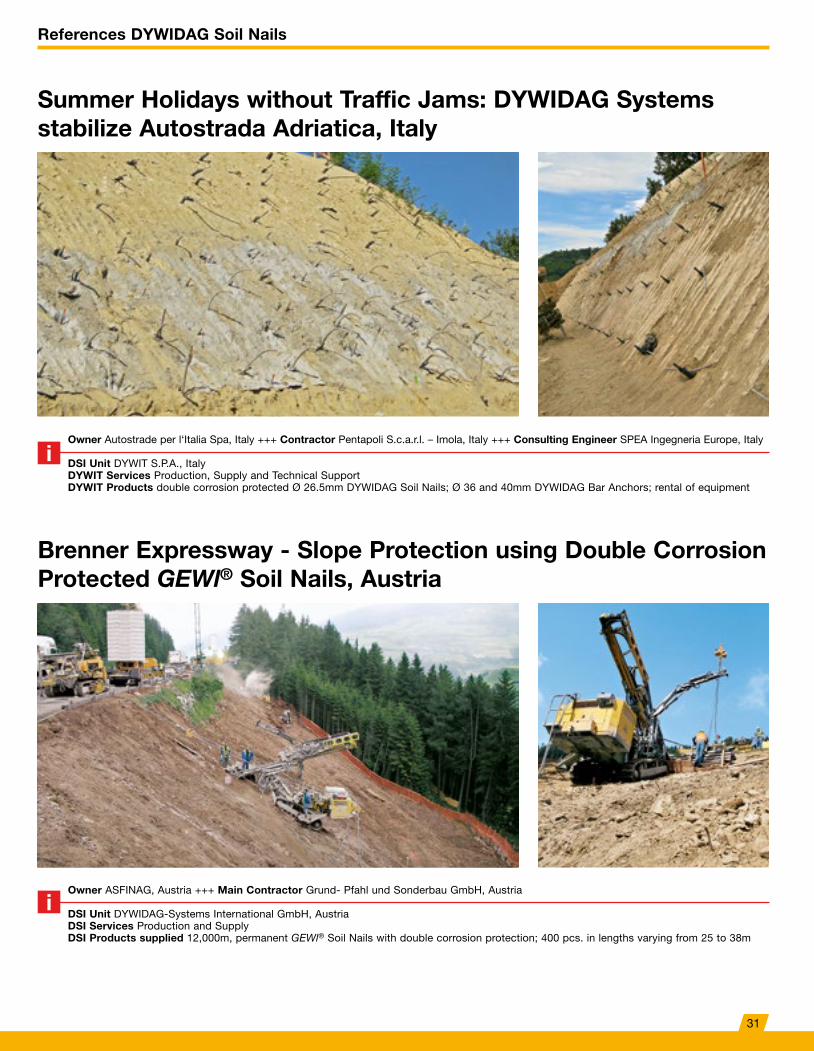
Summer Holidays without Traffic Jams: DYWIDAG Systems stabilize Autostrada Adriatica, Italy
Brenner Expressway - Slope Protection using Double Corrosion Protected GEWl® Soil Nails, Austria
Owner Autostrade per l‘Italia Spa, Italy +++ Contractor Pentapoli S.c.a.r.l. – Imola, Italy +++ Consulting Engineer SPEA Ingegneria Europe, Italy
DSI Unit DYWIT S.P.A., ItalyDYWIT Services Production, Supply and Technical SupportDYWIT Products double corrosion protected Ø 26.5mm DYWIDAG Soil Nails; Ø 36 and 40mm DYWIDAG Bar Anchors; rental of equipment
Owner ASFINAG, Austria +++ Main Contractor Grund- Pfahl und Sonderbau GmbH, Austria
DSI Unit DYWIDAG-Systems International GmbH, AustriaDSI Services Production and Supply DSI Products supplied 12,000m, permanent GEWl® Soil Nails with double corrosion protection; 400 pcs. in lengths varying from 25 to 38m
31
DYWIDAG Rock Bolts
Fields of Application
Fields of Application
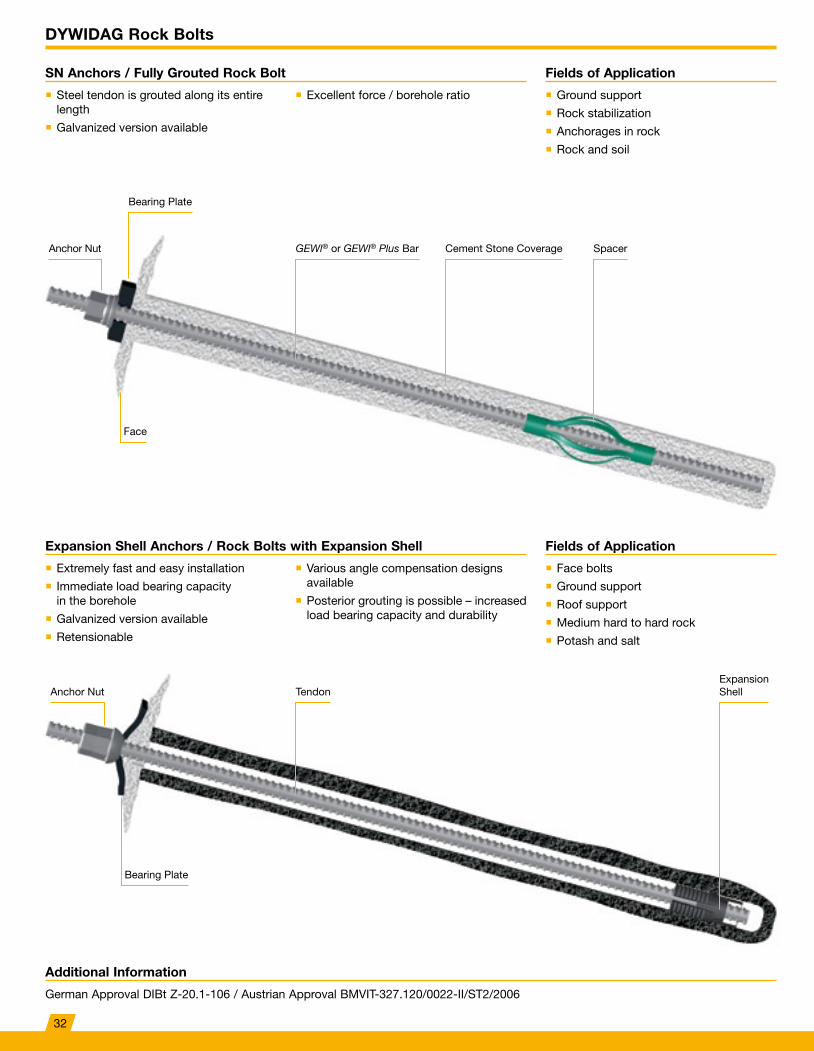
SN Anchors / Fully Grouted Rock Bolt
Expansion Shell Anchors / Rock Bolts with Expansion Shell
� Ground support
� Rock stabilization
� Anchorages in rock
� Rock and soil
� Face bolts
� Ground support
� Roof support
� Medium hard to hard rock
� Potash and salt
� Steel tendon is grouted along its entire length
� Galvanized version available
� Extremely fast and easy installation
� Immediate load bearing capacity in the borehole
� Galvanized version available
� Retensionable
� Excellent force / borehole ratio
� Various angle compensation designs available
� Posterior grouting is possible – increased load bearing capacity and durability
Bearing Plate
Bearing Plate
Anchor Nut
Anchor Nut TendonExpansion Shell
GEWl® or GEWl® Plus Bar SpacerCement Stone Coverage
Additional Information
German Approval DIBt Z-20.1-106 / Austrian Approval BMVIT-327.120/0022-II/ST2/2006
Face
32
References DYWIDAG Rock Bolts
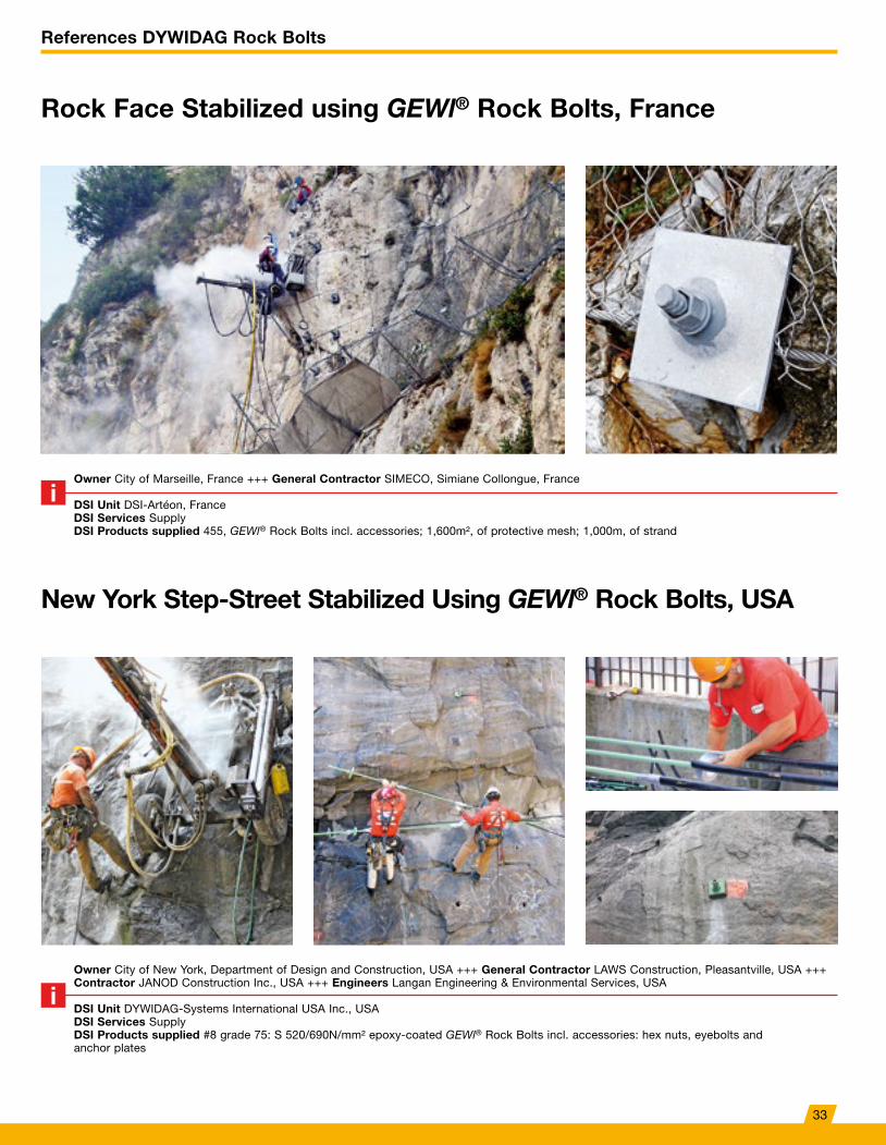
Rock Face Stabilized using GEWl® Rock Bolts, France
New York Step-Street Stabilized Using GEWl® Rock Bolts, USA
Owner City of Marseille, France +++ General Contractor SIMECO, Simiane Collongue, France
DSI Unit DSI-Artéon, FranceDSI Services SupplyDSI Products supplied 455, GEWl® Rock Bolts incl. accessories; 1,600m², of protective mesh; 1,000m, of strand
Owner City of New York, Department of Design and Construction, USA +++ General Contractor LAWS Construction, Pleasantville, USA +++ Contractor JANOD Construction Inc., USA +++ Engineers Langan Engineering & Environmental Services, USA
DSI Unit DYWIDAG-Systems International USA Inc., USADSI Services SupplyDSI Products supplied #8 grade 75: S 520/690N/mm² epoxy-coated GEWl® Rock Bolts incl. accessories: hex nuts, eyebolts and anchor plates
33
DYWI® Drill Hollow Bar System
Additional Information
German Approval DIBt Z-14.4-674 and Z-34.13-208 / Austrian Approval BMVIT-327.120/0010-IV/ST2/2012 / European Approval ETA-12/0603
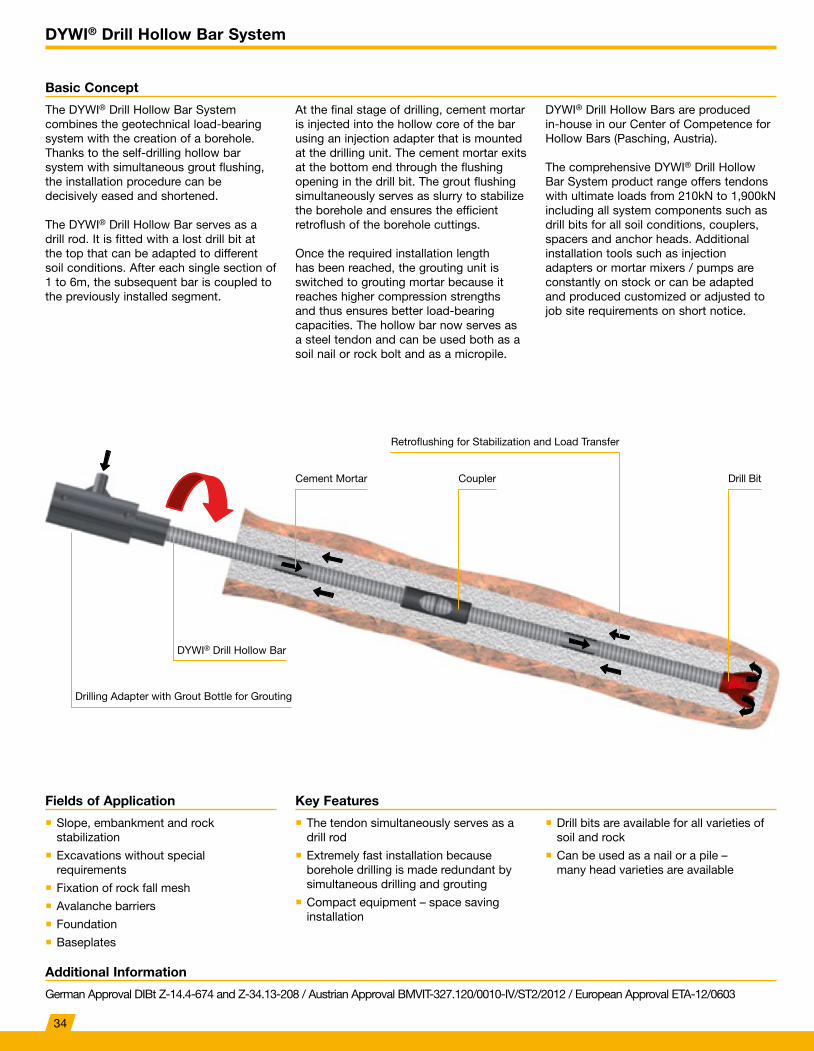
Basic Concept
The DYWI® Drill Hollow Bar System combines the geotechnical load-bearing system with the creation of a borehole. Thanks to the self-drilling hollow bar system with simultaneous grout flushing, the installation procedure can be decisively eased and shortened.
The DYWI® Drill Hollow Bar serves as a drill rod. It is fitted with a lost drill bit at the top that can be adapted to different soil conditions. After each single section of 1 to 6m, the subsequent bar is coupled to the previously installed segment.
At the final stage of drilling, cement mortar is injected into the hollow core of the bar using an injection adapter that is mounted at the drilling unit. The cement mortar exits at the bottom end through the flushing opening in the drill bit. The grout flushing simultaneously serves as slurry to stabilize the borehole and ensures the efficient retroflush of the borehole cuttings.
Once the required installation length has been reached, the grouting unit is switched to grouting mortar because it reaches higher compression strengths and thus ensures better load-bearing capacities. The hollow bar now serves as a steel tendon and can be used both as a soil nail or rock bolt and as a micropile.
DYWI® Drill Hollow Bars are produced in-house in our Center of Competence for Hollow Bars (Pasching, Austria).
The comprehensive DYWI® Drill Hollow Bar System product range offers tendons with ultimate loads from 210kN to 1,900kN including all system components such as drill bits for all soil conditions, couplers, spacers and anchor heads. Additional installation tools such as injection adapters or mortar mixers / pumps are constantly on stock or can be adapted and produced customized or adjusted to job site requirements on short notice.
Key FeaturesFields of Application
� The tendon simultaneously serves as a drill rod
� Extremely fast installation because borehole drilling is made redundant by simultaneous drilling and grouting
� Compact equipment – space saving installation
� Drill bits are available for all varieties of soil and rock
� Can be used as a nail or a pile – many head varieties are available
� Slope, embankment and rock stabilization
� Excavations without special requirements
� Fixation of rock fall mesh
� Avalanche barriers
� Foundation
� Baseplates
Drilling Adapter with Grout Bottle for Grouting
DYWI® Drill Hollow Bar
Cement Mortar Coupler
Retroflushing for Stabilization and Load Transfer
Drill Bit
34
DYWI® Drill Hollow Bar System
Additional Information
German Approval DIBt Z-14.4-674 und Z-34.13-208 / Austrian Approval BMVIT-327.120/0010-IV/ST2/2012 / European Approval ETA-12/0603
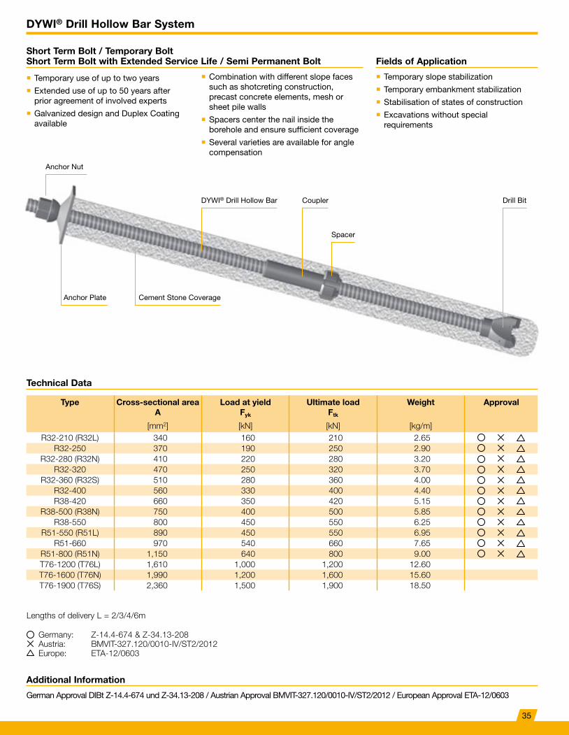
Short Term Bolt / Temporary Bolt Short Term Bolt with Extended Service Life / Semi Permanent Bolt Fields of Application
� Temporary use of up to two years
� Extended use of up to 50 years after prior agreement of involved experts
� Galvanized design and Duplex Coating available
� Combination with different slope faces such as shotcreting construction, precast concrete elements, mesh or sheet pile walls
� Spacers center the nail inside the borehole and ensure sufficient coverage
� Several varieties are available for angle compensation
� Temporary slope stabilization
� Temporary embankment stabilization
� Stabilisation of states of construction
� Excavations without special requirements
Anchor Plate Cement Stone Coverage
Technical Data
Type Cross-sectional areaA
Load at yieldFyk
Ultimate loadFtk
Weight Approval
[mm2] [kN] [kN] [kg/m]R32-210 (R32L) 340 160 210 2.65
R32-250 370 190 250 2.90R32-280 (R32N) 410 220 280 3.20
R32-320 470 250 320 3.70R32-360 (R32S) 510 280 360 4.00
R32-400 560 330 400 4.40R38-420 660 350 420 5.15
R38-500 (R38N) 750 400 500 5.85R38-550 800 450 550 6.25
R51-550 (R51L) 890 450 550 6.95R51-660 970 540 660 7.65
R51-800 (R51N) 1,150 640 800 9.00T76-1200 (T76L) 1,610 1,000 1,200 12.60T76-1600 (T76N) 1,990 1,200 1,600 15.60T76-1900 (T76S) 2,360 1,500 1,900 18.50
Lengths of delivery L = 2/3/4/6m
Anchor Nut
DYWI® Drill Hollow Bar
Spacer
Coupler Drill Bit
Germany: Z-14.4-674 & Z-34.13-208Austria: BMVIT-327.120/0010-IV/ST2/2012Europe: ETA-12/0603
35
References DYWI® Drill Hollow Bar System
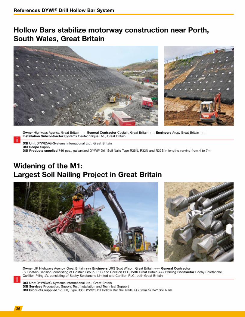
Hollow Bars stabilize motorway construction near Porth, South Wales, Great Britain
Widening of the M1: Largest Soil Nailing Project in Great Britain
Owner Highways Agency, Great Britain +++ General Contractor Costain, Great Britain +++ Engineers Arup, Great Britain +++ Installation Subcontractor Systems Geotechnique Ltd., Great Britain
DSI Unit DYWIDAG-Systems International Ltd., Great BritainDSI Scope Supply DSI Products supplied 746 pcs., galvanized DYWI® Drill Soil Nails Type R25N, R32N and R32S in lengths varying from 4 to 7m
Owner UK Highways Agency, Great Britain +++ Engineers URS Scot Wilson, Great Britain +++ General ContractorJV Costain Carillion, consisting of Costain Group, PLC and Carillion PLC, both Great Britain +++ Drilling Contractor Bachy Soletanche Carillion Piling JV, consisting of Bachy Soletanche Limited and Carillion PLC, both Great Britain
DSI Unit DYWIDAG-Systems International Ltd., Great BritainDSI Services Production, Supply, Test Installation and Technical SupportDSI Products supplied 17,000, Type R38 DYWI® Drill Hollow Bar Soil Nails, Ø 25mm GEWI® Soil Nails
36
References DYWI® Drill Hollow Bar System
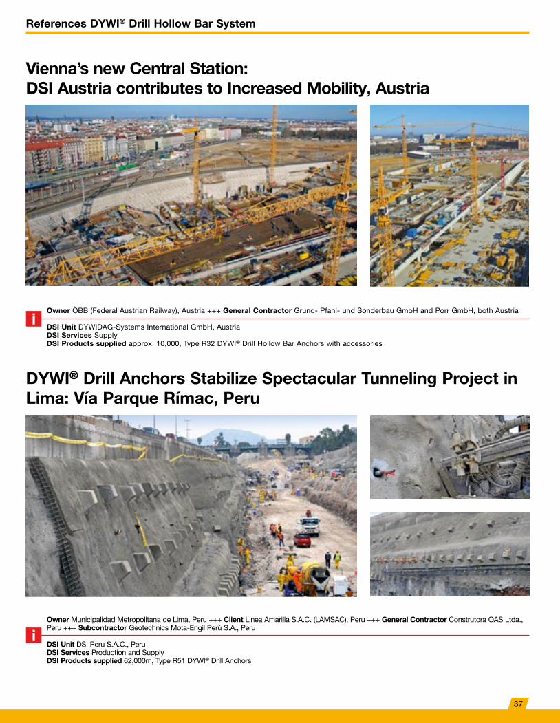
DYWI® Drill Anchors Stabilize Spectacular Tunneling Project in Lima: Vía Parque Rímac, Peru
Owner Municipalidad Metropolitana de Lima, Peru +++ Client Linea Amarilla S.A.C. (LAMSAC), Peru +++ General Contractor Construtora OAS Ltda., Peru +++ Subcontractor Geotechnics Mota-Engil Perú S.A., Peru
DSI Unit DSI Peru S.A.C., PeruDSI Services Production and SupplyDSI Products supplied 62,000m, Type R51 DYWI® Drill Anchors
Vienna’s new Central Station: DSI Austria contributes to Increased Mobility, Austria
Owner ÖBB (Federal Austrian Railway), Austria +++ General Contractor Grund- Pfahl- und Sonderbau GmbH and Porr GmbH, both Austria
DSI Unit DYWIDAG-Systems International GmbH, AustriaDSI Services SupplyDSI Products supplied approx. 10,000, Type R32 DYWI® Drill Hollow Bar Anchors with accessories
37
References DYWI® Drill Hollow Bar System
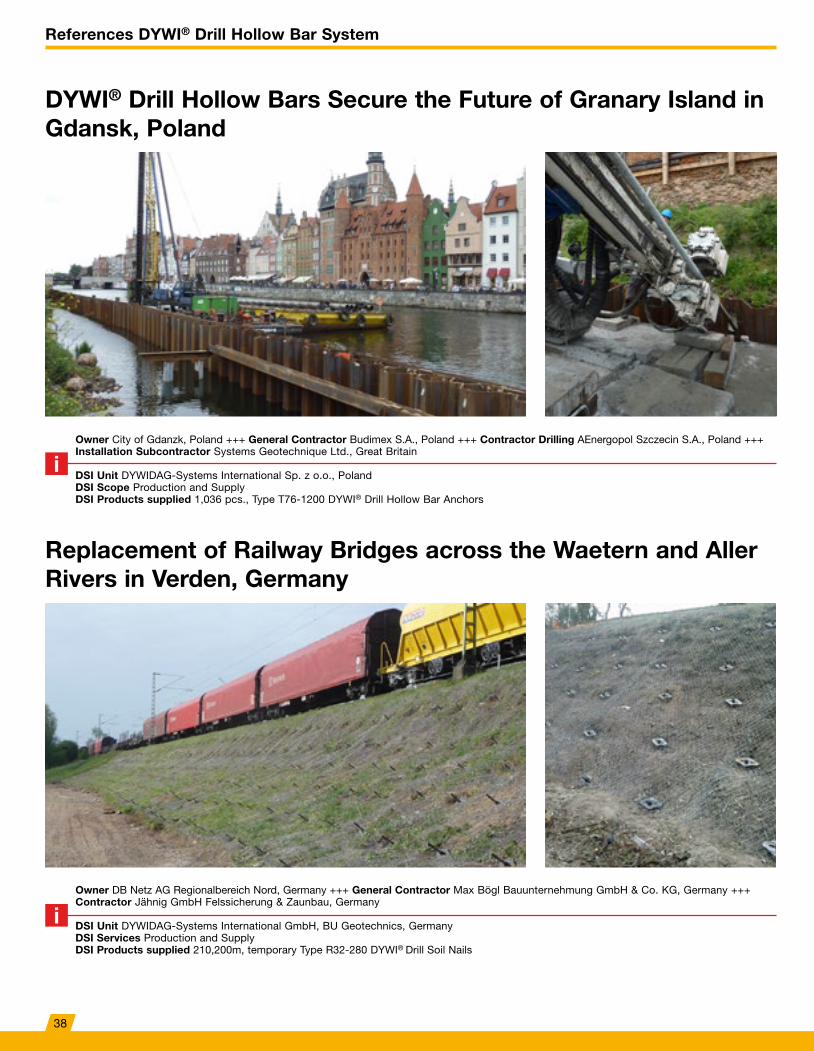
DYWI® Drill Hollow Bars Secure the Future of Granary Island in Gdansk, Poland
Replacement of Railway Bridges across the Waetern and Aller Rivers in Verden, Germany
Owner City of Gdanzk, Poland +++ General Contractor Budimex S.A., Poland +++ Contractor Drilling AEnergopol Szczecin S.A., Poland +++ Installation Subcontractor Systems Geotechnique Ltd., Great Britain
DSI Unit DYWIDAG-Systems International Sp. z o.o., PolandDSI Scope Production and Supply DSI Products supplied 1,036 pcs., Type T76-1200 DYWI® Drill Hollow Bar Anchors
Owner DB Netz AG Regionalbereich Nord, Germany +++ General Contractor Max Bögl Bauunternehmung GmbH & Co. KG, Germany +++ Contractor Jähnig GmbH Felssicherung & Zaunbau, Germany
DSI Unit DYWIDAG-Systems International GmbH, BU Geotechnics, Germany DSI Services Production and SupplyDSI Products supplied 210,200m, temporary Type R32-280 DYWI® Drill Soil Nails
38
References DYWI® Drill Hollow Bar System
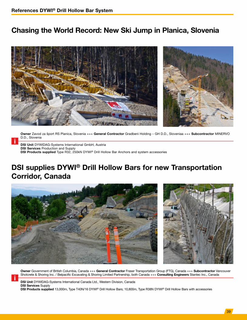
DSI supplies DYWI® Drill Hollow Bars for new Transportation Corridor, Canada
Owner Government of British Columbia, Canada +++ General Contractor Fraser Transportation Group (FTG), Canada +++ Subcontractor Vancouver Shotcrete & Shoring Inc. / Belpacific Excavating & Shoring Limited Partnership, both Canada +++ Consulting Engineers Stantec Inc., Canada
DSI Unit DYWIDAG-Systems International Canada Ltd., Western Division, CanadaDSI Services SupplyDSI Products supplied 13,000m, Type T40N/16 DYWI® Drill Hollow Bars; 10,800m, Type R38N DYWI® Drill Hollow Bars with accessories
Chasing the World Record: New Ski Jump in Planica, Slovenia
Owner Zavod za šport RS Planica, Slovenia +++ General Contractor Gradbeni Holding – GH D.D., Sloveniaa +++ Subcontractor MINERVO D.D., Slovenia
DSI Unit DYWIDAG-Systems International GmbH, AustriaDSI Services Production and SupplyDSI Products supplied Type R32, 250kN DYWI® Drill Hollow Bar Anchors and system accessories
39
DYWIDAG Tie Rods
Additional Information
DYWIDAG Tie Rods Brochure
Basic Concept
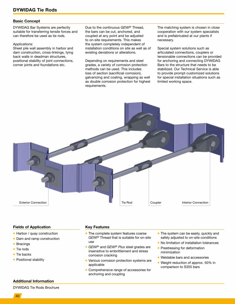
DYWIDAG Bar Systems are perfectly suitable for transferring tensile forces and can therefore be used as tie rods.
Applications: Sheet pile wall assembly in harbor and dam construction, cross-linkings, tying back walls in deadman structures, positional stability of joint connections, corner joints and foundations etc.
Due to the continuous GEWl® Thread, the bars can be cut, anchored, and coupled at any point and be adjusted to on-site requirements. This makes the system completely independent of installation conditions on site as well as of existing deviations or alterations.
Depending on requirements and steel grades, a variety of corrosion protection methods can be used. This includes loss of section (sacrificial corrosion), galvanizing and coating, wrapping as well as double corrosion protection for highest requirements.
The matching system is chosen in close cooperation with our system specialists and is prefabricated at our plants if necessary.
Special system solutions such as articulated connections, couplers or tensionable connections can be provided for anchoring and connecting DYWIDAG Bars to the structure that needs to be stabilized. Our Technical Service is able to provide prompt customized solutions for special installation situations such as limited working space.
Key FeaturesFields of Application
� The complete system features coarse GEWl® Thread that is suitable for on-site use
� GEWl® and GEWl® Plus steel grades are insensitive to embrittlement and stress corrosion cracking
� Various corrosion protection systems are applicable
� Comprehensive range of accessories for anchoring and coupling
� The system can be easily, quickly and safely adjusted to on-site conditions
� No limitation of installation tolerances
� Prestressing for deformation minimization
� Weldable bars and accessories
� Weight reduction of approx. 50% in comparison to S355 bars
� Harbor / quay construction
� Dam and ramp construction
� Bracings
� Tie rods
� Tie backs
� Positional stability
Tie Rod Interior ConnectionExterior Connection Coupler
40
DYWIDAG Tie Rods
Additional Information
DYWIDAG Tie Rods Brochure
Corrosion Protection Systems
Technical Data
Our Sales and Technical Services teams will gladly support you in choosing a suitable corrosion protection system.
� Double Corrosion Protection (DCP) in accordance with EN1537
� Shrinking with corrosion protection shrinking sleeves
� Wrapping with corrosion protection grease tape
� Epoxy-, PUR- or bitumen based coatings
� Hot-dip galvanizing
� Spray galvanizing
� Loss of section (sacrificial corrosion)
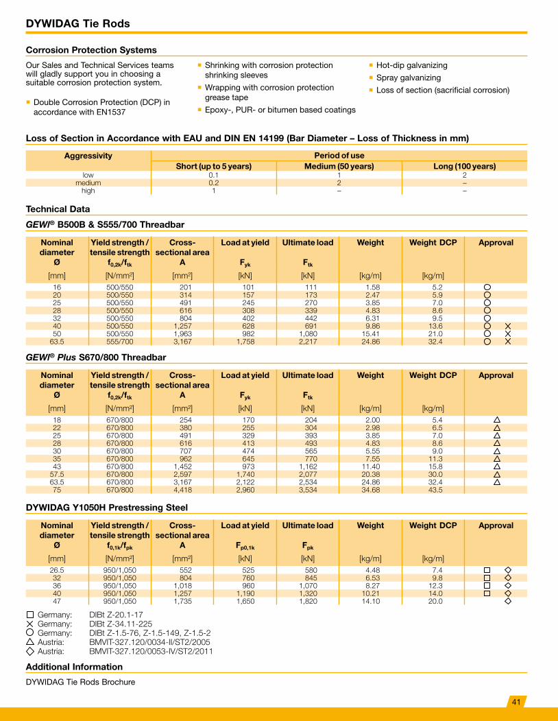
Loss of Section in Accordance with EAU and DIN EN 14199 (Bar Diameter – Loss of Thickness in mm)
Aggressivity Period of useShort (up to 5 years) Medium (50 years) Long (100 years)
low 0.1 1 2medium 0.2 2 –
high 1 – –
GEWl® B500B & S555/700 Threadbar
DYWIDAG Y1050H Prestressing Steel
GEWl® Plus S670/800 Threadbar
Nominal diameter
Ø
Yield strength / tensile strength
f0,2k/ftk
Cross- sectional area
A
Load at yield
Fyk
Ultimate load
Ftk
Weight Weight DCP Approval
[mm] [N/mm²] [mm²] [kN] [kN] [kg/m] [kg/m]16 500/550 201 101 111 1.58 5.220 500/550 314 157 173 2.47 5.925 500/550 491 245 270 3.85 7.028 500/550 616 308 339 4.83 8.632 500/550 804 402 442 6.31 9.540 500/550 1,257 628 691 9.86 13.650 500/550 1,963 982 1,080 15.41 21.0
63.5 555/700 3,167 1,758 2,217 24.86 32.4
Nominal diameter
Ø
Yield strength / tensile strength
f0,1k/fpk
Cross- sectional area
A
Load at yield
Fp0,1k
Ultimate load
Fpk
Weight Weight DCP Approval
[mm] [N/mm²] [mm²] [kN] [kN] [kg/m] [kg/m]26.5 950/1,050 552 525 580 4.48 7.432 950/1,050 804 760 845 6.53 9.836 950/1,050 1,018 960 1,070 8.27 12.340 950/1,050 1,257 1,190 1,320 10.21 14.047 950/1,050 1,735 1,650 1,820 14.10 20.0
Nominal diameter
Ø
Yield strength / tensile strength
f0,2k/ftk
Cross- sectional area
A
Load at yield
Fyk
Ultimate load
Ftk
Weight Weight DCP Approval
[mm] [N/mm²] [mm²] [kN] [kN] [kg/m] [kg/m]18 670/800 254 170 204 2.00 5.422 670/800 380 255 304 2.98 6.525 670/800 491 329 393 3.85 7.028 670/800 616 413 493 4.83 8.630 670/800 707 474 565 5.55 9.035 670/800 962 645 770 7.55 11.343 670/800 1,452 973 1,162 11.40 15.8
57.5 670/800 2,597 1,740 2,077 20.38 30.063.5 670/800 3,167 2,122 2,534 24.86 32.475 670/800 4,418 2,960 3,534 34.68 43.5
Germany: DIBt Z-20.1-17Germany: DIBt Z-34.11-225Germany: DIBt Z-1.5-76, Z-1.5-149, Z-1.5-2Austria: BMVIT-327.120/0034-II/ST2/2005Austria: BMVIT-327.120/0053-IV/ST2/2011
41
DYWIDAG Tie Rods
Tie Rod Connections
Couplers and Connections
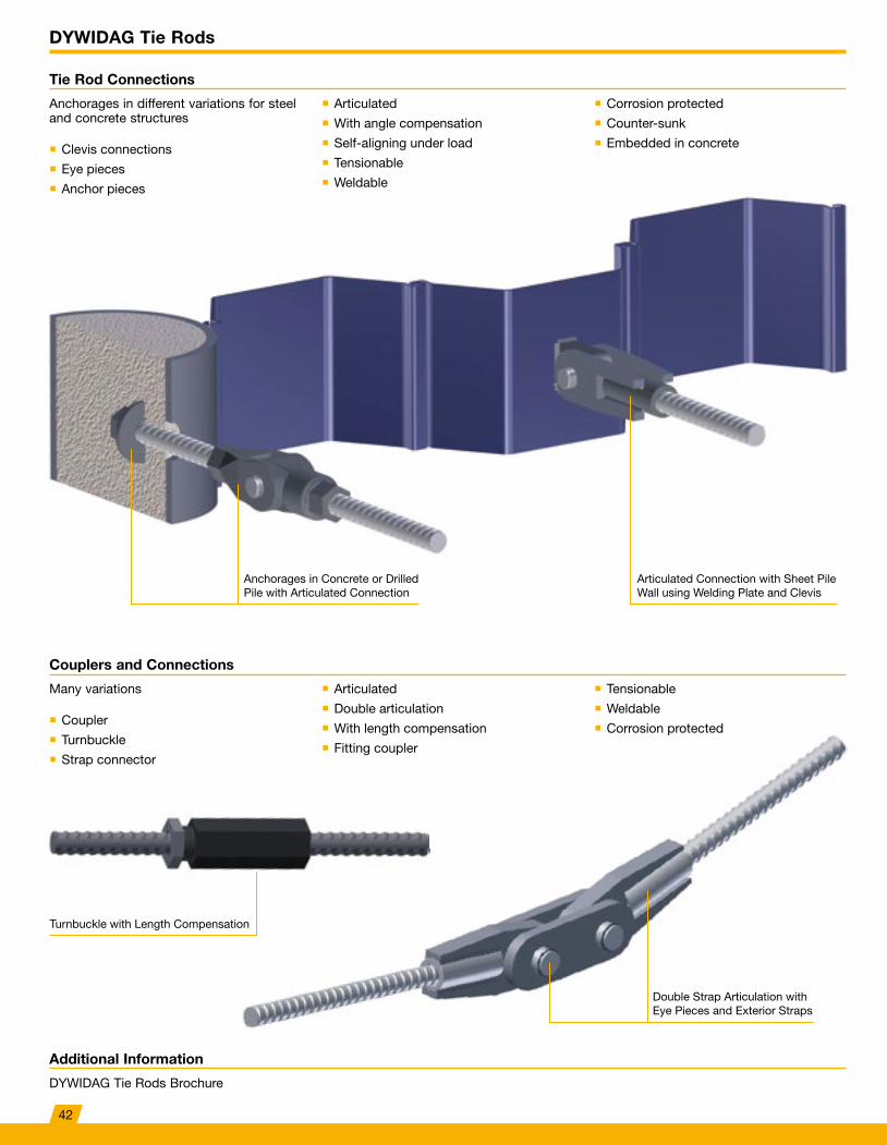
Anchorages in different variations for steel and concrete structures
� Clevis connections
� Eye pieces
� Anchor pieces
Many variations
� Coupler
� Turnbuckle
� Strap connector
� Articulated
� With angle compensation
� Self-aligning under load
� Tensionable
� Weldable
� Articulated
� Double articulation
� With length compensation
� Fitting coupler
� Corrosion protected
� Counter-sunk
� Embedded in concrete
� Tensionable
� Weldable
� Corrosion protected
Additional Information
DYWIDAG Tie Rods Brochure
Anchorages in Concrete or Drilled Pile with Articulated Connection
Turnbuckle with Length Compensation
Articulated Connection with Sheet Pile Wall using Welding Plate and Clevis
Double Strap Articulation with Eye Pieces and Exterior Straps
42
DYWIDAG Tie Rods
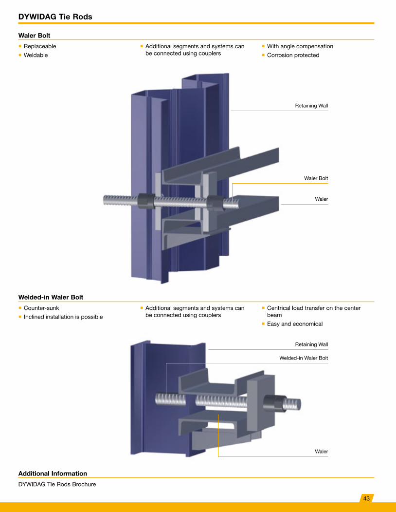
Waler Bolt
Welded-in Waler Bolt
� Replaceable
� Weldable
� Counter-sunk
� Inclined installation is possible
� Additional segments and systems can be connected using couplers
� Additional segments and systems can be connected using couplers
� With angle compensation
� Corrosion protected
� Centrical load transfer on the center beam
� Easy and economical
Additional Information
DYWIDAG Tie Rods Brochure
Retaining Wall
Retaining Wall
Welded-in Waler Bolt
Waler Bolt
Waler
Waler
43
References DYWIDAG Tie Rods
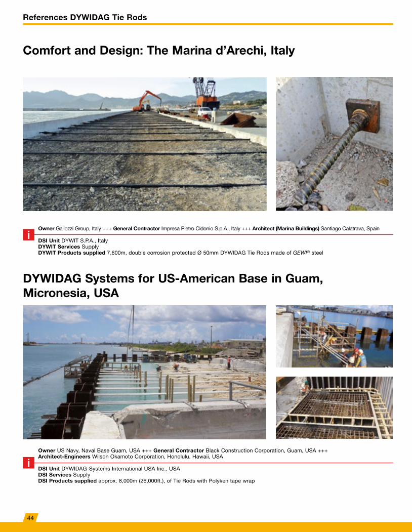
Comfort and Design: The Marina d’Arechi, Italy
DYWIDAG Systems for US-American Base in Guam, Micronesia, USA
Owner Gallozzi Group, Italy +++ General Contractor Impresa Pietro Cidonio S.p.A., Italy +++ Architect (Marina Buildings) Santiago Calatrava, Spain
DSI Unit DYWIT S.P.A., ItalyDYWIT Services SupplyDYWIT Products supplied 7,600m, double corrosion protected Ø 50mm DYWIDAG Tie Rods made of GEWI® steel
Owner US Navy, Naval Base Guam, USA +++ General Contractor Black Construction Corporation, Guam, USA +++Architect-Engineers Wilson Okamoto Corporation, Honolulu, Hawaii, USA
DSI Unit DYWIDAG-Systems International USA Inc., USADSI Services Supply DSI Products supplied approx. 8,000m (26,000ft.), of Tie Rods with Polyken tape wrap
44
References DYWIDAG Tie Rods
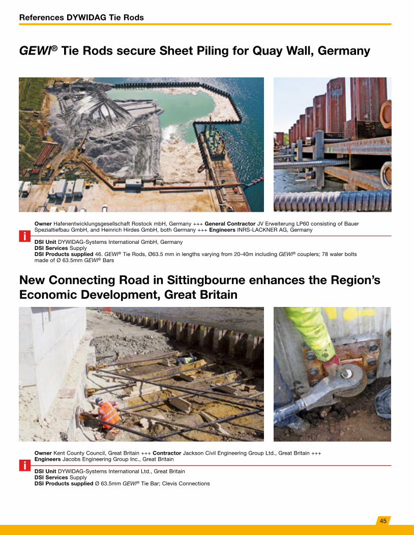
GEWl® Tie Rods secure Sheet Piling for Quay Wall, Germany
New Connecting Road in Sittingbourne enhances the Region’s Economic Development, Great Britain
Owner Hafenentwicklungsgesellschaft Rostock mbH, Germany +++ General Contractor JV Erweiterung LP60 consisting of Bauer Spezialtiefbau GmbH, and Heinrich Hirdes GmbH, both Germany +++ Engineers INRS-LACKNER AG, Germany
DSI Unit DYWIDAG-Systems International GmbH, GermanyDSI Services SupplyDSI Products supplied 46. GEWl® Tie Rods, Ø63.5 mm in lengths varying from 20-40m including GEWl® couplers; 78 waler bolts made of Ø 63.5mm GEWl® Bars
Owner Kent County Council, Great Britain +++ Contractor Jackson Civil Engineering Group Ltd., Great Britain +++ Engineers Jacobs Engineering Group Inc., Great Britain
DSI Unit DYWIDAG-Systems International Ltd., Great BritainDSI Services SupplyDSI Products supplied Ø 63.5mm GEWl® Tie Bar; Clevis Connections
45
The GEWl® System – Connecting Reinforcement
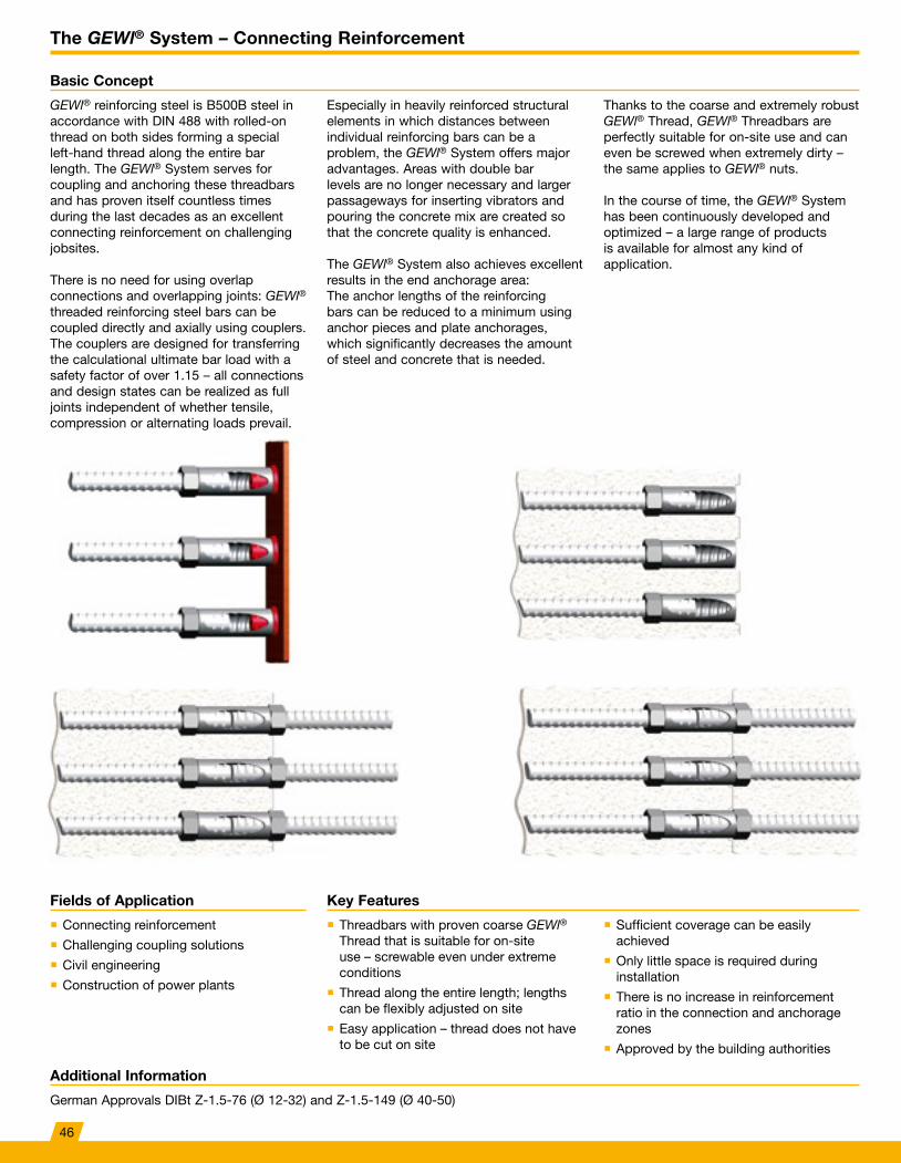
Basic Concept
GEWl® reinforcing steel is B500B steel in accordance with DIN 488 with rolled-on thread on both sides forming a special left-hand thread along the entire bar length. The GEWl® System serves for coupling and anchoring these threadbars and has proven itself countless times during the last decades as an excellent connecting reinforcement on challenging jobsites.
There is no need for using overlap connections and overlapping joints: GEWl® threaded reinforcing steel bars can be coupled directly and axially using couplers. The couplers are designed for transferring the calculational ultimate bar load with a safety factor of over 1.15 – all connections and design states can be realized as full joints independent of whether tensile, compression or alternating loads prevail.
Especially in heavily reinforced structural elements in which distances between individual reinforcing bars can be a problem, the GEWl® System offers major advantages. Areas with double bar levels are no longer necessary and larger passageways for inserting vibrators and pouring the concrete mix are created so that the concrete quality is enhanced.
The GEWl® System also achieves excellent results in the end anchorage area: The anchor lengths of the reinforcing bars can be reduced to a minimum using anchor pieces and plate anchorages, which significantly decreases the amount of steel and concrete that is needed.
Thanks to the coarse and extremely robust GEWl® Thread, GEWl® Threadbars are perfectly suitable for on-site use and can even be screwed when extremely dirty – the same applies to GEWl® nuts.
In the course of time, the GEWl® System has been continuously developed and optimized – a large range of products is available for almost any kind of application.
Key FeaturesFields of Application
� Threadbars with proven coarse GEWl® Thread that is suitable for on-site use – screwable even under extreme conditions
� Thread along the entire length; lengths can be flexibly adjusted on site
� Easy application – thread does not have to be cut on site
� Sufficient coverage can be easily achieved
� Only little space is required during installation
� There is no increase in reinforcement ratio in the connection and anchorage zones
� Approved by the building authorities
� Connecting reinforcement
� Challenging coupling solutions
� Civil engineering
� Construction of power plants
Additional Information
German Approvals DIBt Z-1.5-76 (Ø 12-32) and Z-1.5-149 (Ø 40-50)
46
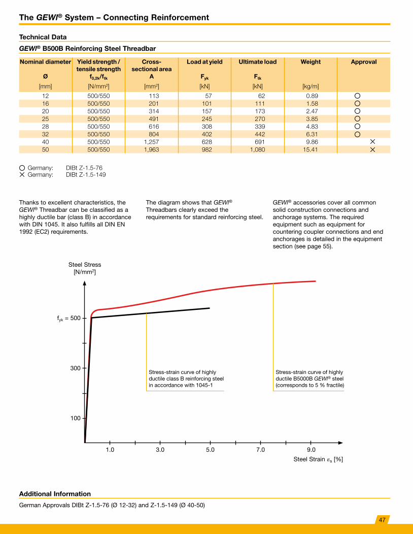
The GEWl® System – Connecting Reinforcement
Thanks to excellent characteristics, the GEWl® Threadbar can be classified as a highly ductile bar (class B) in accordance with DIN 1045. It also fulfills all DIN EN 1992 (EC2) requirements.
The diagram shows that GEWl® Threadbars clearly exceed the requirements for standard reinforcing steel.
fyk = 500
Steel Strain «s [%]
Steel Stress [N/mm2]
300
100
1.0 3.0 5.0 7.0 9.0
GEWl® accessories cover all common solid construction connections and anchorage systems. The required equipment such as equipment for countering coupler connections and end anchorages is detailed in the equipment section (see page 55).
Additional Information
German Approvals DIBt Z-1.5-76 (Ø 12-32) and Z-1.5-149 (Ø 40-50)
GEWl® B500B Reinforcing Steel Threadbar
Technical Data
Nominal diameter Ø
Yield strength / tensile strength
f0,2k/ftk
Cross- sectional area
A
Load at yield
Fyk
Ultimate load
Ftk
Weight Approval
[mm] [N/mm²] [mm²] [kN] [kN] [kg/m]
12 500/550 113 57 62 0.8916 500/550 201 101 111 1.5820 500/550 314 157 173 2.4725 500/550 491 245 270 3.8528 500/550 616 308 339 4.8332 500/550 804 402 442 6.3140 500/550 1,257 628 691 9.8650 500/550 1,963 982 1,080 15.41
Germany: DIBt Z-1.5-76Germany: DIBt Z-1.5-149
Stress-strain curve of highly ductile class B reinforcing steel in accordance with 1045-1
Stress-strain curve of highly ductile B5000B GEWl® steel (corresponds to 5 % fractile)
47
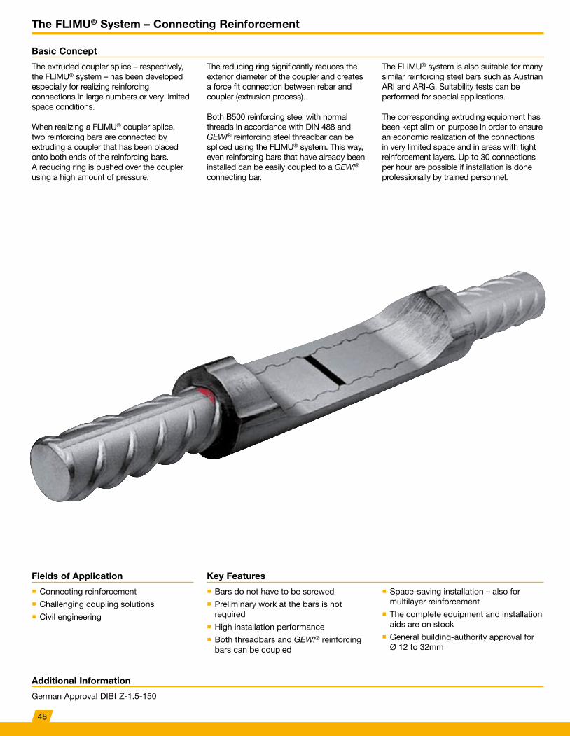
The FLIMU® System – Connecting Reinforcement
Basic Concept
The extruded coupler splice – respectively, the FLIMU® system – has been developed especially for realizing reinforcing connections in large numbers or very limited space conditions.
When realizing a FLIMU® coupler splice, two reinforcing bars are connected by extruding a coupler that has been placed onto both ends of the reinforcing bars. A reducing ring is pushed over the coupler using a high amount of pressure.
The reducing ring significantly reduces the exterior diameter of the coupler and creates a force fit connection between rebar and coupler (extrusion process).
Both B500 reinforcing steel with normal threads in accordance with DIN 488 and GEWl® reinforcing steel threadbar can be spliced using the FLIMU® system. This way, even reinforcing bars that have already been installed can be easily coupled to a GEWl® connecting bar.
The FLIMU® system is also suitable for many similar reinforcing steel bars such as Austrian ARI and ARI-G. Suitability tests can be performed for special applications.
The corresponding extruding equipment has been kept slim on purpose in order to ensure an economic realization of the connections in very limited space and in areas with tight reinforcement layers. Up to 30 connections per hour are possible if installation is done professionally by trained personnel.
Key FeaturesFields of Application
� Bars do not have to be screwed
� Preliminary work at the bars is not required
� High installation performance
� Both threadbars and GEWl® reinforcing bars can be coupled
� Space-saving installation – also for multilayer reinforcement
� The complete equipment and installation aids are on stock
� General building-authority approval for Ø 12 to 32mm
� Connecting reinforcement
� Challenging coupling solutions
� Civil engineering
Additional Information
German Approval DIBt Z-1.5-150
48
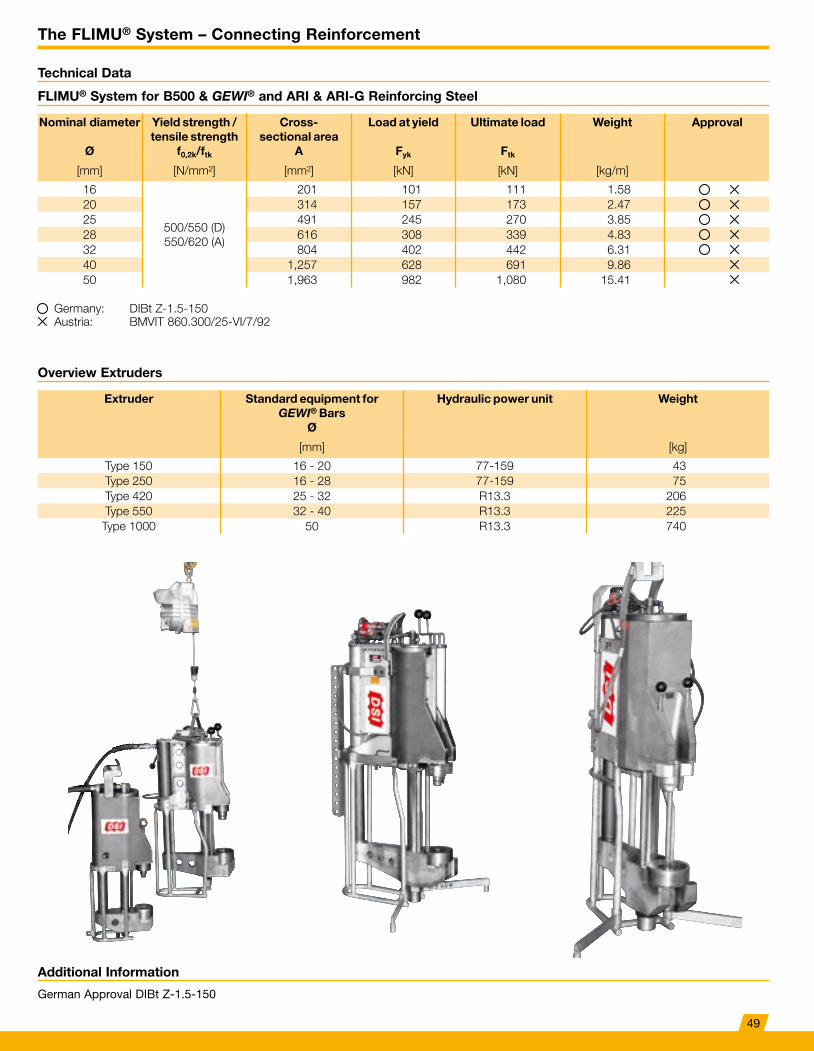
The FLIMU® System – Connecting Reinforcement
Additional Information
German Approval DIBt Z-1.5-150
FLIMU® System for B500 & GEWI® and ARI & ARI-G Reinforcing Steel
Technical Data
Overview Extruders
Nominal diameter Ø
Yield strength / tensile strength
f0,2k/ftk
Cross- sectional area
A
Load at yield
Fyk
Ultimate load
Ftk
Weight Approval
[mm] [N/mm²] [mm²] [kN] [kN] [kg/m]
16
500/550 (D)550/620 (A)
201 101 111 1.5820 314 157 173 2.4725 491 245 270 3.8528 616 308 339 4.8332 804 402 442 6.3140 1,257 628 691 9.8650 1,963 982 1,080 15.41
Extruder Standard equipment for GEWI® Bars
Ø
Hydraulic power unit Weight
[mm] [kg]
Type 150 16 - 20 77-159 43Type 250 16 - 28 77-159 75Type 420 25 - 32 R13.3 206Type 550 32 - 40 R13.3 225
Type 1000 50 R13.3 740
Germany: DIBt Z-1.5-150Austria: BMVIT 860.300/25-VI/7/92
49
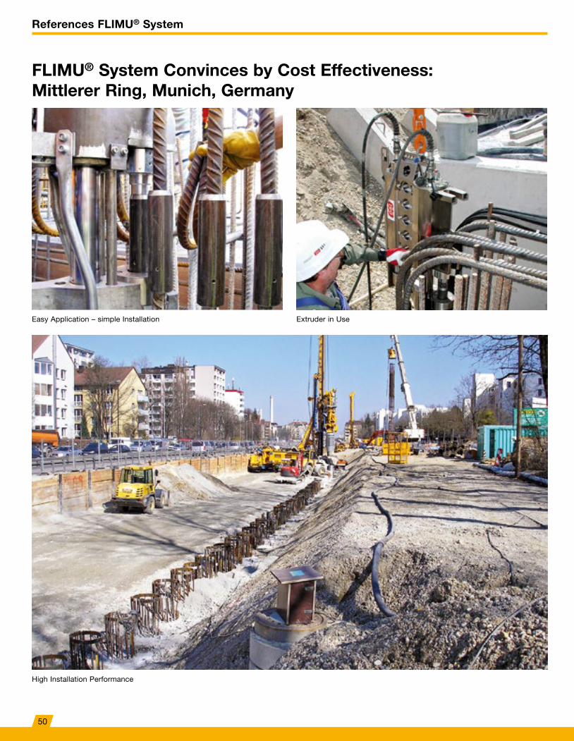
References FLIMU® System
FLIMU® System Convinces by Cost Effectiveness: Mittlerer Ring, Munich, Germany
Easy Application – simple Installation
High Installation Performance
Extruder in Use
50
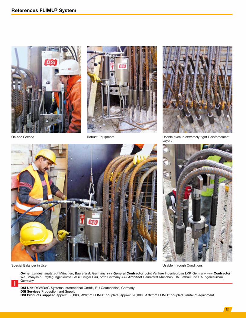
References FLIMU® System
Owner Landeshauptstadt München, Baureferat, Germany +++ General Contractor Joint Venture Ingenieurbau LKP, Germany +++ Contractor W&F (Wayss & Freytag Ingenieurbau AG); Berger Bau, both Germany +++ Architect Baureferat München, HA Tiefbau und HA Ingenieurbau, Germany
DSI Unit DYWIDAG-Systems International GmbH, BU Geotechnics, GermanyDSI Services Production and Supply DSI Products supplied approx. 35,000, Ø28mm FLIMU® couplers; approx. 20,000, Ø 32mm FLIMU® couplers; rental of equipment
On-site Service
Special Balancer in Use
Robust Equipment Usable even in extremely tight Reinforcement Layers
Usable in rough Conditions
51
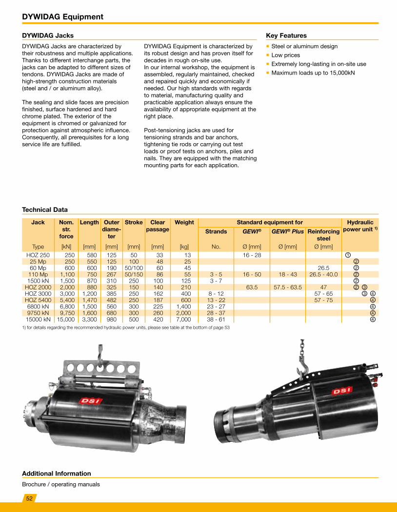
DYWIDAG Equipment
DYWIDAG Jacks
DYWIDAG Jacks are characterized by their robustness and multiple applications. Thanks to different interchange parts, the jacks can be adapted to different sizes of tendons. DYWIDAG Jacks are made of high-strength construction materials (steel and / or aluminum alloy).
The sealing and slide faces are precision finished, surface hardened and hard chrome plated. The exterior of the equipment is chromed or galvanized for protection against atmospheric influence. Consequently, all prerequisites for a long service life are fulfilled.
DYWIDAG Equipment is characterized by its robust design and has proven itself for decades in rough on-site use. In our internal workshop, the equipment is assembled, regularly maintained, checked and repaired quickly and economically if needed. Our high standards with regards to material, manufacturing quality and practicable application always ensure the availability of appropriate equipment at the right place.
Post-tensioning jacks are used for tensioning strands and bar anchors, tightening tie rods or carrying out test loads or proof tests on anchors, piles and nails. They are equipped with the matching mounting parts for each application.
Key Features
� Steel or aluminum design
� Low prices
� Extremely long-lasting in on-site use
� Maximum loads up to 15,000kN
Additional Information
Brochure / operating manuals
Technical Data
Jack Nom. str.
force
Length Outer diame-
ter
Stroke Clear passage
Weight Standard equipment for Hydraulic power unit 1)
Strands GEWI® GEWI® Plus Reinforcing steel
Type [kN] [mm] [mm] [mm] [mm] [kg] No. Ø [mm] Ø [mm] Ø [mm]HOZ 250 250 580 125 50 33 13 16 - 28
25 Mp 250 550 125 100 48 2560 Mp 600 600 190 50/100 60 45 26.5110 Mp 1,100 750 267 50/150 86 55 3 - 5 16 - 50 18 - 43 26.5 - 40.01500 kN 1,500 870 310 250 100 125 3 - 7
HOZ 2000 2,000 880 325 150 140 210 63.5 57.5 - 63.5 47HOZ 3000 3,000 1,200 385 250 162 400 8 - 12 57 - 65HOZ 5400 5,400 1,470 482 250 187 600 13 - 22 57 - 756800 kN 6,800 1,500 560 300 225 1,400 23 - 279750 kN 9,750 1,600 680 300 260 2,000 28 - 3715000 kN 15,000 3,300 980 500 420 7,000 38 - 61
1) for details regarding the recommended hydraulic power units, please see table at the bottom of page 53
122222 3
3 44444
52
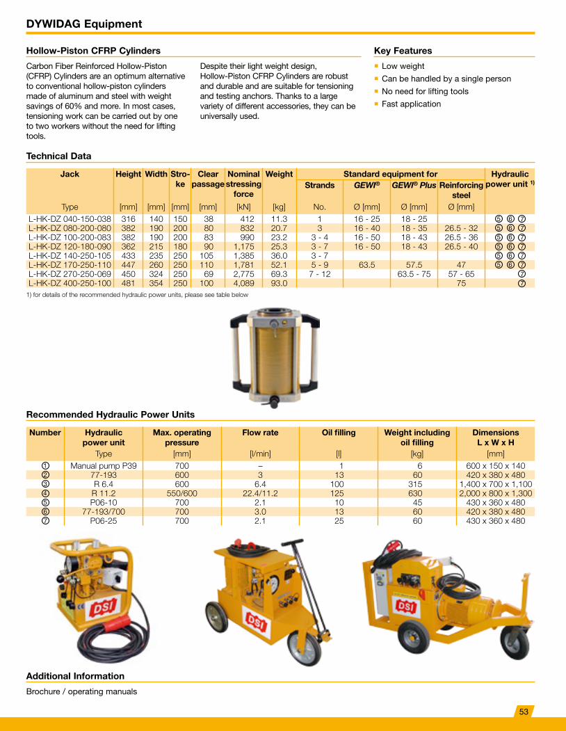
DYWIDAG Equipment
Hollow-Piston CFRP Cylinders
Carbon Fiber Reinforced Hollow-Piston (CFRP) Cylinders are an optimum alternative to conventional hollow-piston cylinders made of aluminum and steel with weight savings of 60% and more. In most cases, tensioning work can be carried out by one to two workers without the need for lifting tools.
Despite their light weight design, Hollow-Piston CFRP Cylinders are robust and durable and are suitable for tensioning and testing anchors. Thanks to a large variety of different accessories, they can be universally used.
Key Features
� Low weight
� Can be handled by a single person
� No need for lifting tools
� Fast application
Additional Information
Brochure / operating manuals
Technical Data
Jack Height Width Stro-ke
Clear passage
Nominal stressing
force
Weight Standard equipment for Hydraulic power unit 1)Strands GEWI® GEWI® Plus Reinforcing
steelType [mm] [mm] [mm] [mm] [kN] [kg] No. Ø [mm] Ø [mm] Ø [mm]
L-HK-DZ 040-150-038 316 140 150 38 412 11.3 1 16 - 25 18 - 25L-HK-DZ 080-200-080 382 190 200 80 832 20.7 3 16 - 40 18 - 35 26.5 - 32L-HK-DZ 100-200-083 382 190 200 83 990 23.2 3 - 4 16 - 50 18 - 43 26.5 - 36L-HK-DZ 120-180-090 362 215 180 90 1,175 25.3 3 - 7 16 - 50 18 - 43 26.5 - 40L-HK-DZ 140-250-105 433 235 250 105 1,385 36.0 3 - 7L-HK-DZ 170-250-110 447 260 250 110 1,781 52.1 5 - 9 63.5 57.5 47L-HK-DZ 270-250-069 450 324 250 69 2,775 69.3 7 - 12 63.5 - 75 57 - 65L-HK-DZ 400-250-100 481 354 250 100 4,089 93.0 75
1) for details of the recommended hydraulic power units, please see table below
Number Hydraulic power unit
Max. operating pressure
Flow rate Oil filling Weight including oil filling
Dimensions L x W x H
Type [mm] [l/min] [l] [kg] [mm]Manual pump P39 700 – 1 6 600 x 150 x 140
77-193 600 3 13 60 420 x 380 x 480R 6.4 600 6.4 100 315 1,400 x 700 x 1,100
R 11.2 550/600 22.4/11.2 125 630 2,000 x 800 x 1,300P06-10 700 2.1 10 45 430 x 360 x 480
77-193/700 700 3.0 13 60 420 x 380 x 480P06-25 700 2.1 25 60 430 x 360 x 480
555555
666666
1234567
77777777
Recommended Hydraulic Power Units
53
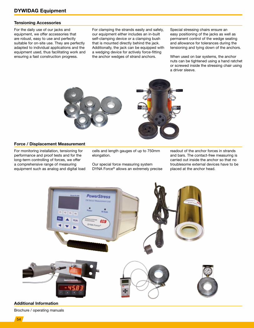
DYWIDAG Equipment
Tensioning Accessories
Force / Displacement Measurement
For the daily use of our jacks and equipment, we offer accessories that are robust, easy to use and perfectly suitable for on-site use. They are perfectly adapted to individual applications and the equipment used, thus facilitating work and ensuring a fast construction progress.
For monitoring installation, tensioning for performance and proof tests and for the long-term controlling of forces, we offer a comprehensive range of measuring equipment such as analog and digital load
For clamping the strands easily and safely, our equipment either includes an in-built self-clamping device or a clamping bush that is mounted directly behind the jack. Additionally, the jack can be equipped with a wedging device for actively force-fitting the anchor wedges of strand anchors.
cells and length gauges of up to 750mm elongation.
Our special force measuring system DYNA Force® allows an extremely precise
Special stressing chairs ensure an easy positioning of the jacks as well as permanent control of the wedge seating and allowance for tolerances during the tensioning and tying down of the anchors.
When used on bar systems, the anchor nuts can be tightened using a hand ratchet or screwed inside the stressing chair using a driver sleeve.
readout of the anchor forces in strands and bars. The contact-free measuring is carried out inside the anchor so that no troublesome external devices have to be placed at the anchor head.
Additional Information
Brochure / operating manuals
54
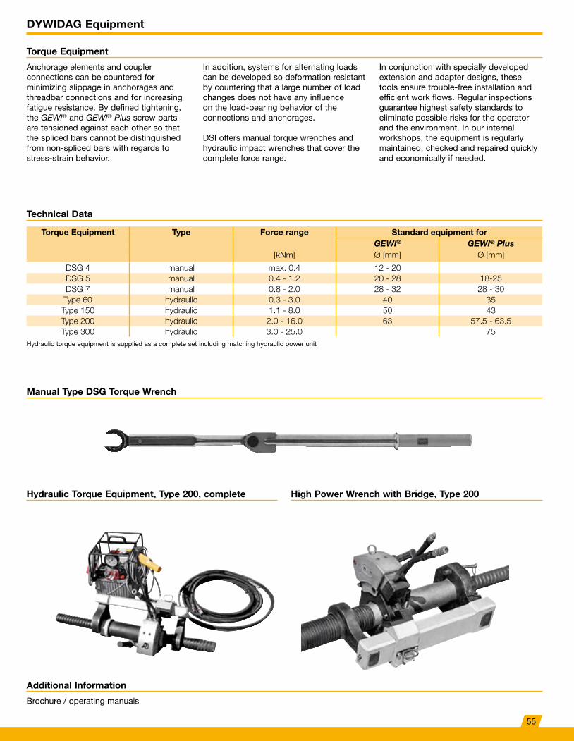
DYWIDAG Equipment
Torque Equipment
Manual Type DSG Torque Wrench
Hydraulic Torque Equipment, Type 200, complete High Power Wrench with Bridge, Type 200
Anchorage elements and coupler connections can be countered for minimizing slippage in anchorages and threadbar connections and for increasing fatigue resistance. By defined tightening, the GEWl® and GEWl® Plus screw parts are tensioned against each other so that the spliced bars cannot be distinguished from non-spliced bars with regards to stress-strain behavior.
In addition, systems for alternating loads can be developed so deformation resistant by countering that a large number of load changes does not have any influence on the load-bearing behavior of the connections and anchorages.
DSI offers manual torque wrenches and hydraulic impact wrenches that cover the complete force range.
In conjunction with specially developed extension and adapter designs, these tools ensure trouble-free installation and efficient work flows. Regular inspections guarantee highest safety standards to eliminate possible risks for the operator and the environment. In our internal workshops, the equipment is regularly maintained, checked and repaired quickly and economically if needed.
Additional Information
Brochure / operating manuals
Technical Data
Torque Equipment Type Force range Standard equipment forGEWI® GEWI® Plus
[kNm] Ø [mm] Ø [mm]
DSG 4 manual max. 0.4 12 - 20DSG 5 manual 0.4 - 1.2 20 - 28 18-25DSG 7 manual 0.8 - 2.0 28 - 32 28 - 30Type 60 hydraulic 0.3 - 3.0 40 35
Type 150 hydraulic 1.1 - 8.0 50 43Type 200 hydraulic 2.0 - 16.0 63 57.5 - 63.5Type 300 hydraulic 3.0 - 25.0 75
Hydraulic torque equipment is supplied as a complete set including matching hydraulic power unit
55
Rudeška cesta 179, Zagreb, 10000, Tel: 01-301-3890; Fax: 01-302-8576; [email protected]; www.comiter.hr
Rudeška cesta 179, Zagreb, 10000, Tel: 01-301-3890; Fax: 01-302-8576; [email protected]; www.comiter.hr