Embed Size (px)
Citation preview
DYWIDAG Soil Nails
Dallas Cowboy Stadium, Dallas, TX

Part of the extensive and ambitious expansion of Dallas/Fort Worth Airport included numerous roadways in and
around the congested airport infrastructure. Some roads required significant cuts and retaining walls next to many existing bridges, buildings and roadways. In order to support the adjacent structures and roads, more than 16,400 ft DYWIDAG Soil Nails were installed. The soil nail method of construction allo-wed for the least disruption of the adjacent structures and movement of people and vehicles. Soil Nail retaining walls require minimum excavation and are installed faster than alternate types of retaining walls.
San Manuel Indian Casino, Highland, CA
Owner Dallas/Fort Worth International Airport, TX, USA +++ Contractor Craig Olden, Inc., Little Elm, TX, USA +++ Installed by Craig Olden, Inc., Little Elm, TX, USADSI Scope Supply of approximately 650 DYWIDAG Soil Nails size #8, total length about 16,400 ft
i
Owner San Manuel Band of Mission Indians, Highland, CA, USA +++ General Contractor Bomel Construction Anaheim, CA, USA +++ Constructor Pennhall Company, Las Vegas, NV, USA +++ Subcontractor Condon-Johnson & Assoc., San Diego, CA, USA +++ Engineers PB&A (Pirooz Barar & Assoc.), San Anselmo, CA, USA
DSI Unit DSI USA, BU Geotechnics, Long Beach, CA, USADSI Scope Supply of 481 double corrosion protected DYWIDAG soil nails #8 grade 75: S 520/690 N/mm², 193 double corrosion protected DYWIDAG V-Nails #8 grade 75: S 520/690 N/mm² and #8 grade 75: S 520/690 N/mm² test nails
References
Retaining Wall at Dallas/Fort Worth International Airport, TX Secured with DYWIDAG Soil Nails
i
3
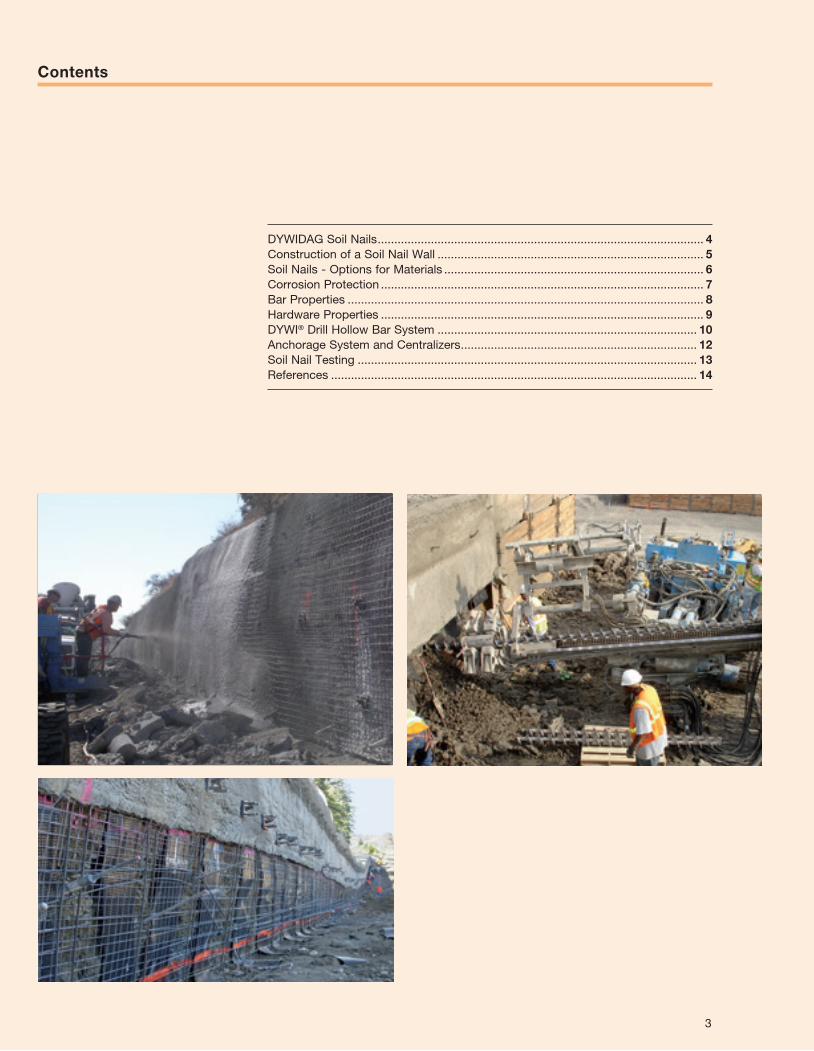
DYWIDAG Soil Nails .................................................................................................. 4Construction of a Soil Nail Wall ................................................................................ 5Soil Nails - Options for Materials .............................................................................. 6Corrosion Protection ................................................................................................. 7Bar Properties ........................................................................................................... 8Hardware Properties ................................................................................................. 9DYWI® Drill Hollow Bar System .............................................................................. 10Anchorage System and Centralizers ....................................................................... 12Soil Nail Testing ...................................................................................................... 13References .............................................................................................................. 14
Contents
surcharge
existing grade
drainagedrivingforces
varies
wal
l he
ight
resistingforces
soil nail adheres tosoil on bothsides offailure surface
bottom of wall
cip andarchitectural
treatment
primaryshotcrete wall
assumedfailuresurface
History
The technique of soil nailing began to evolve in the early 1970’s. Major research programs in Germany in the mid to late 70’s and in France in the late 80’s advanced this method of construction. It has been success-fully utilized worldwide for excavation support and slope stabilization and its use continues to grow rapidly.
General Notes
Applying the principles of systematic rock anchoring to soil seems to be obvious, but the requirements for soil nailing are higher. The many years of experience gained with pressure-grouted anchors have resulted in a certain level of standards, however,
the stability of the supported soil mass must be verified for all stages. Soil nails are used for stabilizing slopes and excavations. They find an efficient application in granular soils of medium to high density with sufficient internal friction, so that a good load transfer along the soil nail is possible, and only slight creep movements occur in the supported soil mass. The soil nails are installed as the excavation progresses from top to bottom. The surface of the cut is usually stabilized by shotcrete and rebar mats.
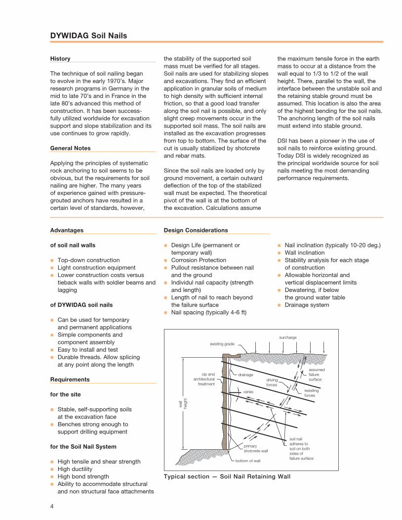
Since the soil nails are loaded only by ground movement, a certain outward deflection of the top of the stabilized wall must be expected. The theoretical pivot of the wall is at the bottom of the excavation. Calculations assume
the maximum tensile force in the earth mass to occur at a distance from the wall equal to 1/3 to 1/2 of the wall height. There, parallel to the wall, the interface between the unstable soil and the retaining stable ground must be assumed. This location is also the area of the highest bending for the soil nails. The anchoring length of the soil nails must extend into stable ground.
DSI has been a pioneer in the use of soil nails to reinforce existing ground. Today DSI is widely recognized as the principal worldwide source for soil nails meeting the most demanding performance requirements.
Advantages
of soil nail walls
n Top-down constructionn Light construction equipmentn Lower construction costs versus
tieback walls with soldier beams and lagging
of DYWIDAG soil nails
n Can be used for temporary and permanent applications
n Simple components and component assembly
n Easy to install and testn Durable threads. Allow splicing
at any point along the length
Requirements
for the site
n Stable, self-supporting soils at the excavation face
n Benches strong enough to support drilling equipment
for the Soil Nail System
n High tensile and shear strengthn High ductilityn High bond strengthn Ability to accommodate structural
and non structural face attachments
Design Considerations
n Design Life (permanent or temporary wall)
n Corrosion Protectionn Pullout resistance between nail
and the groundn Individul nail capacity (strength
and length)n Length of nail to reach beyond
the failure surfacen Nail spacing (typically 4-6 ft)
Typical section — Soil Nail Retaining Wall
n Nail inclination (typically 10-20 deg.)n Wall inclinationn Stability analysis for each stage
of constructionn Allowable horizontal and
vertical displacement limitsn Dewatering, if below
the ground water tablen Drainage system
DYWIDAG Soil Nails
4

Construction of a Soil Nail Wall
Excavate soil
Drill hole
Install and grout nail
Test selected nails
Place reinforcement
Place shotcrete
Finish shotcrete
Install soil nail plate, washers and nut
Excavate for the next level of nails
5
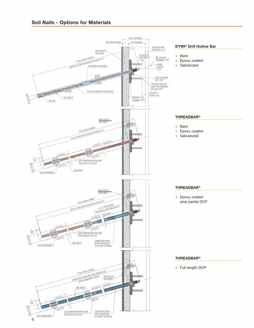
DYWI® Drill Hollow Bar
n Baren Epoxy coatedn Galvanized
THREADBAR®
n Baren Epoxy coatedn Galvanized
THREADBAR®
n Epoxy coated plus partial DCP
THREADBAR®
n Full length DCP
ANGLE VARIES
(TYP.)
TOTAL LENGTH (VARIES)
DRILLED HOLE
DRILL BIT
WALL THICKNESS
HOLLOW-CORE SELF-DRILLING ROD
FIELD GROUT
COUPLERS AS REQUIRED
SHOTCRETE FACING
BACK FACE OFSHOTCRETE
CONCRETE ANCHOR USED FOR PERMANENT SOIL NAILS (TYP.)
BEARING PLATE ASSEMBLY (TYP.)
CONCRETE COVER (TYP.)
CL
ARCHITECTURAL TREATMENT (TYP.)
SOIL NAIL ASSEMBLY (TYP.)
BEVEL WASHERS SET (TYP.)
HEX NUT OR ANCHOR NUT (TYP.)
CIP CONCRETE
BARE OR HOT-DIP GALVANIZED PER ASTM A153
SOLID REINFORCING STEEL BARPER ASTM A615 OR A722
EPOXY COATED PER ASTM A934 OR ASTM A775
TOTAL LENGTH (VARIES)
HOLE CENTRALIZER
3"CLR.
DRILLED HOLE NAIL GROUT
BACK FACE OFSHOTCRETE
LENGTH
UNCOATED
TOTAL LENGTH (VARIES)
L = 3'-0" CORRUGATED
SHEATHING SHOP PREGROUTED
EPOXY COATED PER ASTM A934 OR ASTM A775
BACK FACE OFSHOTCRETE
LENGTH
UNCOATED
DRILLED HOLE HOLE CENTRALIZER
3"CLR. SOLID REINFORCING STEEL BAR
PER ASTM A615 OR A722
NAIL GROUT CORRUGATED HDPE OR PVC SHEATHING 40 MIL MIN. THICKNESS
TOTAL LENGTH (VARIES)
3"CLR.
DRILLED HOLE HOLE CENTRALIZER
NAIL GROUT
PER ASTM A615 OR A722SOLID REINFORCING STEEL BAR
UNCOATEDLENGTH
CORRUGATED SHEATHING SHOP PREGROUTED
ENTIRE EMBEDMENT LENGTH BACK FACE OFSHOTCRETE
CORRUGATED HDPE OR PVC SHEATHING 40 MIL MIN. THICKNESS
Soil Nails - Options for Materials
6
Corrosion Protection
DYWIDAG soil nails can be protected against corrosion in a variety of ways suitable for both temporary (<24 months) and permanent (>24 months) applications.
Bare bar in cement grout
Cement grout alone can be used for corrosion protection of temporary soil nails and permanent nails in non-aggressive ground provided the thickness of the grout cover exceeds 1-1/2“ (38 mm). The DYWI® Drill bar system is ideally suited for temporary soil nails particularly in non-cohesive soils.
Sacrificial steel
Steel elements of the soil nail system can be oversized to allow for loss of cross sectional area due to corrosion. The rate of corrosion shall be based on historical data for ground conditions with the same or lower level of aggressiveness. Additional factors of safety are recommended.
Hot Dip Galvanizing
Permanent soil nails in non-aggressive ground can be protected against corrosion by hot dip galvanizing in accordance with ASTM A-153. Hot dip galvanizing of GR150 bars requires specialized procedures to avoid hydrogen embrittlement.
Epoxy coating
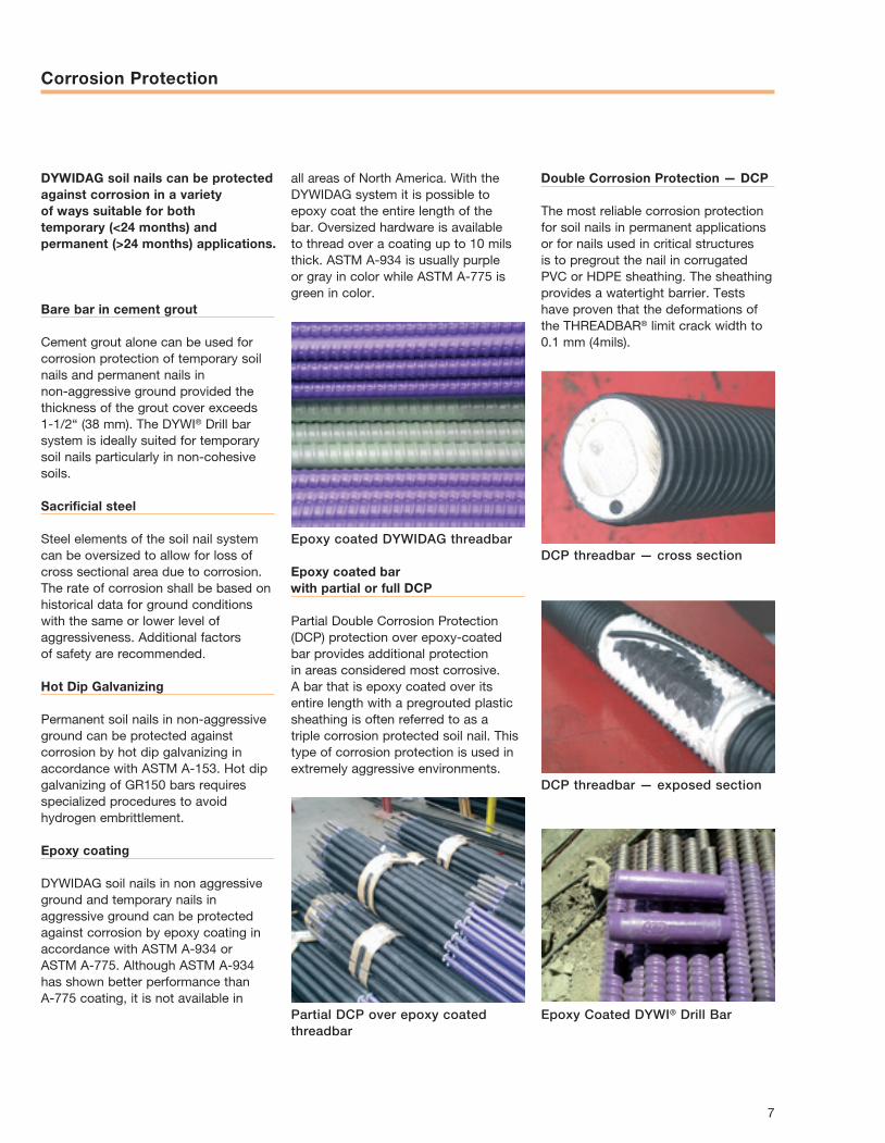
DYWIDAG soil nails in non aggressive ground and temporary nails in aggressive ground can be protected against corrosion by epoxy coating in accordance with ASTM A-934 or ASTM A-775. Although ASTM A-934 has shown better performance than A-775 coating, it is not available in
Epoxy coated bar with partial or full DCP
Partial Double Corrosion Protection (DCP) protection over epoxy-coated bar provides additional protection in areas considered most corrosive. A bar that is epoxy coated over its entire length with a pregrouted plastic sheathing is often referred to as a triple corrosion protected soil nail. This type of corrosion protection is used in extremely aggressive environments.
Double Corrosion Protection — DCP
The most reliable corrosion protection for soil nails in permanent applications or for nails used in critical structures is to pregrout the nail in corrugated PVC or HDPE sheathing. The sheathing provides a watertight barrier. Tests have proven that the deformations of the THREADBAR® limit crack width to 0.1 mm (4mils).
Epoxy coated DYWIDAG threadbar
Partial DCP over epoxy coated threadbar
DCP threadbar — cross section
DCP threadbar — exposed section
Epoxy Coated DYWI® Drill Bar
all areas of North America. With the DYWIDAG system it is possible to epoxy coat the entire length of the bar. Oversized hardware is available to thread over a coating up to 10 mils thick. ASTM A-934 is usually purple or gray in color while ASTM A-775 is green in color.
7
Bar Properties
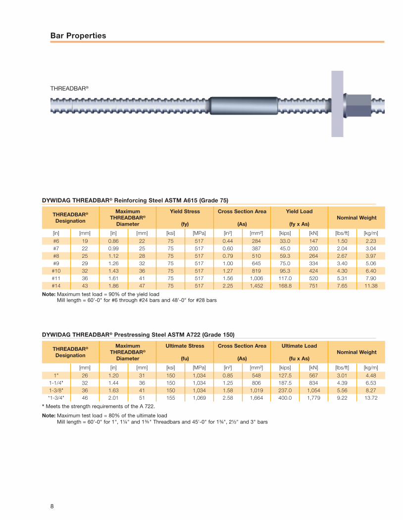
DYWIDAG THREADBAR® Reinforcing Steel ASTM A615 (Grade 75)
DYWIDAG THREADBAR® Prestressing Steel ASTM A722 (Grade 150)
THREADBAR®
8
THREADBAR®
Designation
Maximum THREADBAR®
Diameter
Yield Stress
(fy)
Cross Section Area
(As)
Yield Load
(fy x As)Nominal Weight
[in] [mm] [in] [mm] [ksi] [MPa] [in²] [mm²] [kips] [kN] [lbs/ft] [kg/m]
#6 19 0.86 22 75 517 0.44 284 33.0 147 1.50 2.23#7 22 0.99 25 75 517 0.60 387 45.0 200 2.04 3.04#8 25 1.12 28 75 517 0.79 510 59.3 264 2.67 3.97#9 29 1.26 32 75 517 1.00 645 75.0 334 3.40 5.06#10 32 1.43 36 75 517 1.27 819 95.3 424 4.30 6.40#11 36 1.61 41 75 517 1.56 1,006 117.0 520 5.31 7.90#14 43 1.86 47 75 517 2.25 1,452 168.8 751 7.65 11.38
Note: Maximum test load = 90% of the yield load Mill length = 60'-0" for #6 through #24 bars and 48'-0" for #28 bars
THREADBAR®
Designation
Maximum THREADBAR®
Diameter
Ultimate Stress
(fu)
Cross Section Area
(As)
Ultimate Load
(fu x As)Nominal Weight
[mm] [in] [mm] [ksi] [MPa] [in²] [mm²] [kips] [kN] [lbs/ft] [kg/m]
1" 26 1.20 31 150 1,034 0.85 548 127.5 567 3.01 4.481-1/4" 32 1.44 36 150 1,034 1.25 806 187.5 834 4.39 6.531-3/8" 36 1.63 41 150 1,034 1.58 1,019 237.0 1,054 5.56 8.27*1-3/4" 46 2.01 51 155 1,069 2.58 1,664 400.0 1,779 9.22 13.72
* Meets the strength requirements of the A 722.
Note: Maximum test load = 80% of the ultimate load Mill length = 60'-0" for 1", 1¼" and 1 " Threadbars and 45'-0" for 1¾", 2½" and 3" bars
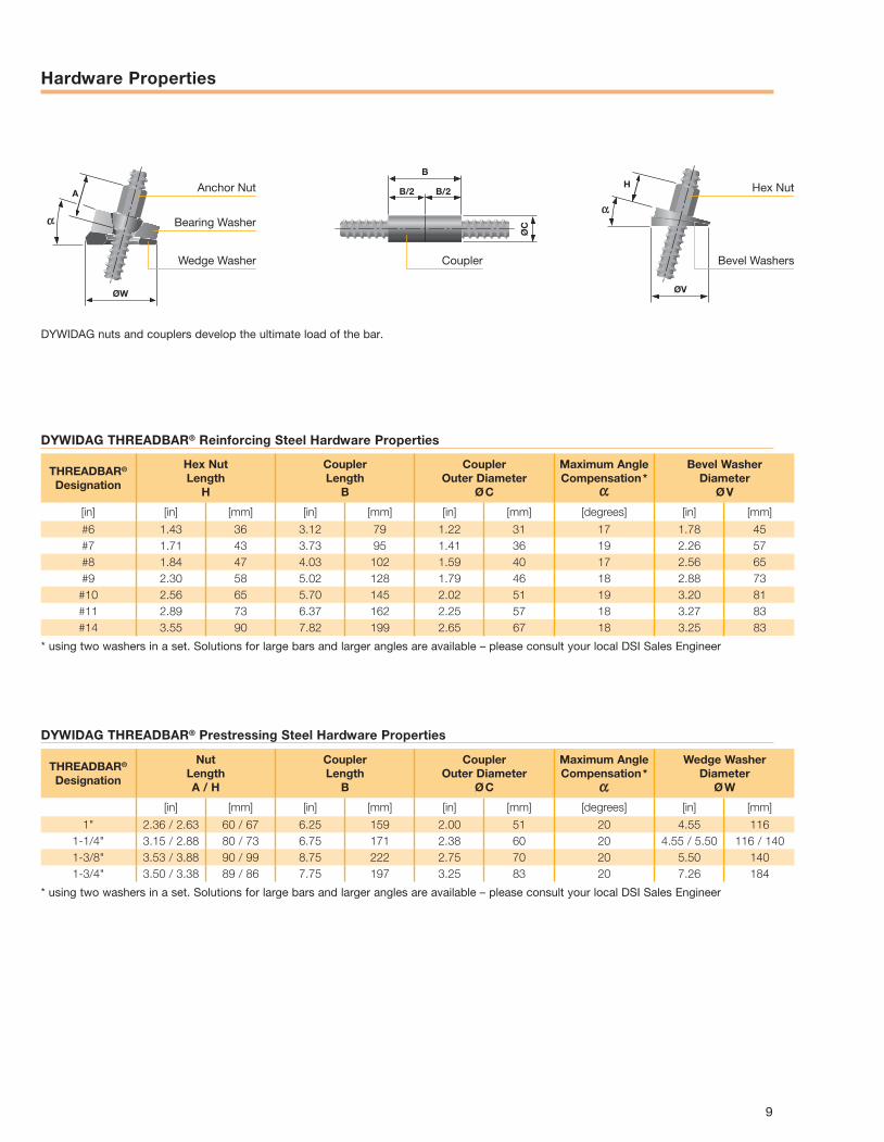
Hardware Properties
DYWIDAG THREADBAR® Reinforcing Steel Hardware Properties
DYWIDAG THREADBAR® Prestressing Steel Hardware Properties
9
THREADBAR®
Designation
Hex Nut Length
H
Coupler Length
B
Coupler Outer Diameter
Ø C
Maximum Angle Compensation *
Bevel Washer Diameter
Ø V
[in] [in] [mm] [in] [mm] [in] [mm] [degrees] [in] [mm]
#6 1.43 36 3.12 79 1.22 31 17 1.78 45#7 1.71 43 3.73 95 1.41 36 19 2.26 57#8 1.84 47 4.03 102 1.59 40 17 2.56 65#9 2.30 58 5.02 128 1.79 46 18 2.88 73#10 2.56 65 5.70 145 2.02 51 19 3.20 81#11 2.89 73 6.37 162 2.25 57 18 3.27 83#14 3.55 90 7.82 199 2.65 67 18 3.25 83
* using two washers in a set. Solutions for large bars and larger angles are available – please consult your local DSI Sales Engineer
THREADBAR®
Designation
Nut Length A / H
Coupler Length
B
Coupler Outer Diameter
Ø C
Maximum Angle Compensation *
Wedge Washer Diameter
Ø W
[in] [mm] [in] [mm] [in] [mm] [degrees] [in] [mm]
1" 2.36 / 2.63 60 / 67 6.25 159 2.00 51 20 4.55 1161-1/4" 3.15 / 2.88 80 / 73 6.75 171 2.38 60 20 4.55 / 5.50 116 / 1401-3/8" 3.53 / 3.88 90 / 99 8.75 222 2.75 70 20 5.50 1401-3/4" 3.50 / 3.38 89 / 86 7.75 197 3.25 83 20 7.26 184
* using two washers in a set. Solutions for large bars and larger angles are available – please consult your local DSI Sales Engineer
A
ØW
H
ØV
B
B/2 B/2
ØC
Anchor Nut
Bearing Washer
Wedge Washer Coupler
Hex Nut
Bevel Washers
DYWIDAG nuts and couplers develop the ultimate load of the bar.
DYWI® Drill Hollow Bar System
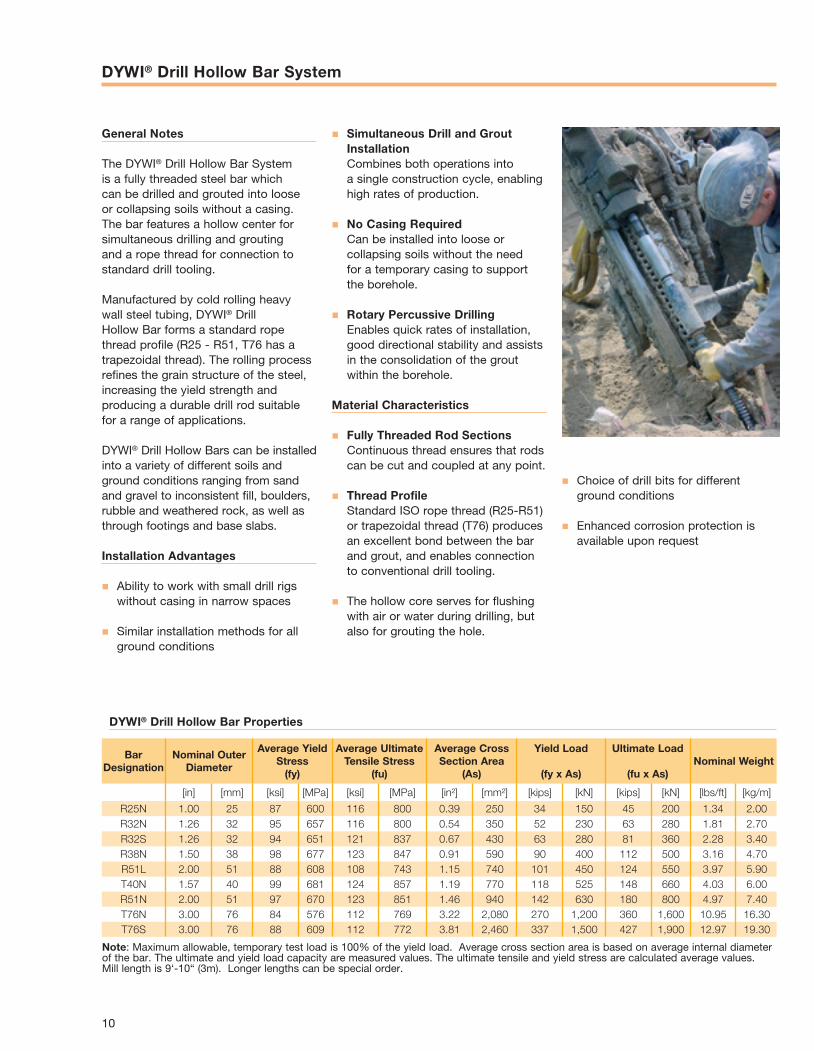
General Notes
The DYWI® Drill Hollow Bar System is a fully threa ded steel bar which can be drilled and grouted into loose or collapsing soils without a casing. The bar features a hollow center for simultaneous drilling and grouting and a rope thread for connection to standard drill tooling.
Manufactured by cold rolling heavy wall steel tubing, DYWI® Drill Hollow Bar forms a standard rope thread profile (R25 - R51, T76 has a trapezoidal thread). The rolling process refines the grain structure of the steel, increasing the yield strength and producing a durable drill rod suitable for a range of applications.
DYWI® Drill Hollow Bars can be installed into a variety of different soils and ground conditions ranging from sand and gravel to inconsistent fill, boulders, rubble and weathered rock, as well as through foo tings and base slabs.
Installation Advantages
n Ability to work with small drill rigs without casing in narrow spaces
n Similar installation methods for all ground conditions
n Simultaneous Drill and Grout Installation Combines both operations into a single construction cycle, enabling high rates of production.
n No Casing Required Can be installed into loose or collapsing soils without the need for a temporary casing to support the borehole.
n Rotary Percussive Drilling Enables quick rates of installation, good directional stability and assists in the consolidation of the grout within the borehole.
Material Characteristics
n Fully Threaded Rod Sections Continuous thread ensures that rods can be cut and coupled at any point.
n Thread Profile Standard ISO rope thread (R25-R51) or trapezoidal thread (T76) produces an excellent bond between the bar and grout, and enables connection to conventional drill tooling.
n The hollow core serves for flushing with air or water during drilling, but also for grouting the hole.
n Choice of drill bits for different ground conditions
n Enhanced corrosion protection is available upon request
DYWI® Drill Hollow Bar Properties
10
Bar Designation
Nominal Outer Diameter
Average Yield Stress
(fy)
Average Ultimate Tensile Stress
(fu)
Average Cross Section Area
(As)
Yield Load
(fy x As)
Ultimate Load
(fu x As)Nominal Weight
[in] [mm] [ksi] [MPa] [ksi] [MPa] [in²] [mm²] [kips] [kN] [kips] [kN] [lbs/ft] [kg/m]
R25N 1.00 25 87 600 116 800 0.39 250 34 150 45 200 1.34 2.00R32N 1.26 32 95 657 116 800 0.54 350 52 230 63 280 1.81 2.70R32S 1.26 32 94 651 121 837 0.67 430 63 280 81 360 2.28 3.40R38N 1.50 38 98 677 123 847 0.91 590 90 400 112 500 3.16 4.70R51L 2.00 51 88 608 108 743 1.15 740 101 450 124 550 3.97 5.90T40N 1.57 40 99 681 124 857 1.19 770 118 525 148 660 4.03 6.00R51N 2.00 51 97 670 123 851 1.46 940 142 630 180 800 4.97 7.40T76N 3.00 76 84 576 112 769 3.22 2,080 270 1,200 360 1,600 10.95 16.30T76S 3.00 76 88 609 112 772 3.81 2,460 337 1,500 427 1,900 12.97 19.30
Note: Maximum allowable, temporary test load is 100% of the yield load. Average cross section area is based on average internal diameter of the bar. The ultimate and yield load capacity are measured values. The ultimate tensile and yield stress are calculated average values. Mill length is 9‘-10“ (3m). Longer lengths can be special order.

couplerhexnut
domed or flat bearing plate
hollow bar cement grout
drill bit(various drill bits are available for different ground conditions)
Bar / Grout bond
DYWI® Drill Hollow Bar Hardware Properties
11
BarDesignation
Hex Nut Length
H
Coupler Length
B
Coupler Outer Diameter
Ø C
Maximum Angle Compensation *
Bevel Washer Diameter
Ø V
[in] [mm] [in] [mm] [in] [mm] [degrees] [in] [mm]
R25N 2.44 62 5.91 150 1.46 37 19 2.26 57R32N 2.56 65 6.30 160 1.65 42 18 2.88 73R32S 2.56 65 6.30 160 1.65 42 18 2.88 73R38N 3.15 80 7.09 180 2.01 51 19 3.20 81R51L 3.54 90 7.87 200 2.48 63T40N 2.68 68 6.30 160 2.24 57 18 3.27 83R51N 3.54 90 7.87 200 2.48 63T76N 3.15 80 8.66 220 3.82 97T76S 3.15 80 8.66 220 3.82 97
* using two washers in a set. Solutions for large bars and larger angles are available – please consult your local DSI Sales Engineer
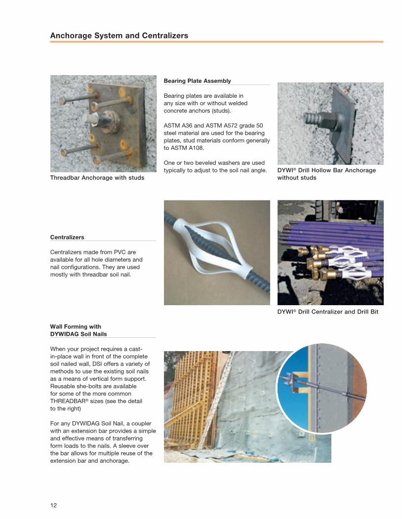
Anchorage System and Centralizers
Centralizers
Centralizers made from PVC are available for all hole diameters and nail configurations. They are used mostly with threadbar soil nail.
Wall Forming with DYWIDAG Soil Nails
When your project requires a cast-in-place wall in front of the complete soil nailed wall, DSI offers a variety of methods to use the existing soil nails as a means of vertical form support. Reusable she-bolts are available for some of the more common THREADBAR® sizes (see the detail to the right)
For any DYWIDAG Soil Nail, a coupler with an extension bar provides a simple and effective means of transferring form loads to the nails. A sleeve over the bar allows for multiple reuse of the extension bar and anchorage.
Bearing Plate Assembly
Bearing plates are available in any size with or without welded concrete anchors (studs).
ASTM A36 and ASTM A572 grade 50 steel material are used for the bearing plates, stud materials conform generally to ASTM A108.
One or two beveled washers are used typically to adjust to the soil nail angle. DYWI® Drill Hollow Bar Anchorage
without studs
DYWI® Drill Centralizer and Drill Bit
Threadbar Anchorage with studs
12
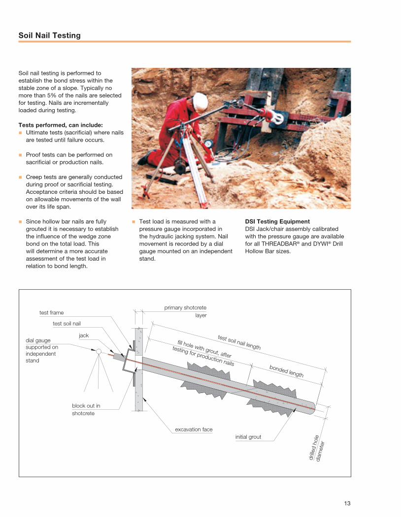
Soil Nail Testing
Soil nail testing is performed to establish the bond stress within the stable zone of a slope. Typically no more than 5% of the nails are selected for testing. Nails are incrementally loaded during testing.
Tests performed, can include:n Ultimate tests (sacrificial) where nails
are tested until failure occurs.
n Proof tests can be performed on sacrificial or production nails.
n Creep tests are generally conducted during proof or sacrificial testing. Acceptance criteria should be based on allowable movements of the wall over its life span.
n Since hollow bar nails are fully grouted it is necessary to establish the influence of the wedge zone bond on the total load. This will determine a more accurate assessment of the test load in relation to bond length.
initial grout
drille
d ho
ledi
amet
er
excavation face
block out in
dial gaugesupported on independentstand
shotcrete
jack
test soil nail
test frameprimary shotcrete
layer
test soil nail lengthfill hole with grout, after
testing for production nails bonded length
DSI Testing EquipmentDSI Jack/chair assembly calibrated with the pressure gauge are available for all THREADBAR® and DYWI® Drill Hollow Bar sizes.
n Test load is measured with a pressure gauge incorporated in the hydraulic jacking system. Nail movement is recorded by a dial gauge mounted on an independent stand.
13
References
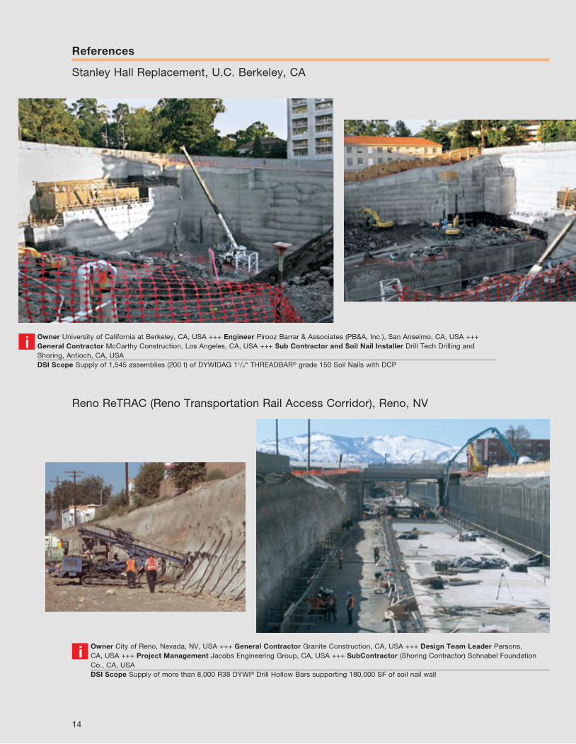
Stanley Hall Replacement, U.C. Berkeley, CA
Owner University of California at Berkeley, CA, USA +++ Engineer Pirooz Barrar & Associates (PB&A, Inc.), San Anselmo, CA, USA +++ General Contractor McCarthy Construction, Los Angeles, CA, USA +++ Sub Contractor and Soil Nail Installer Drill Tech Drilling and Shoring, Antioch, CA, USADSI Scope Supply of 1,545 assemblies (200 t) of DYWIDAG 11/4“ THREADBAR® grade 150 Soil Nails with DCP
i
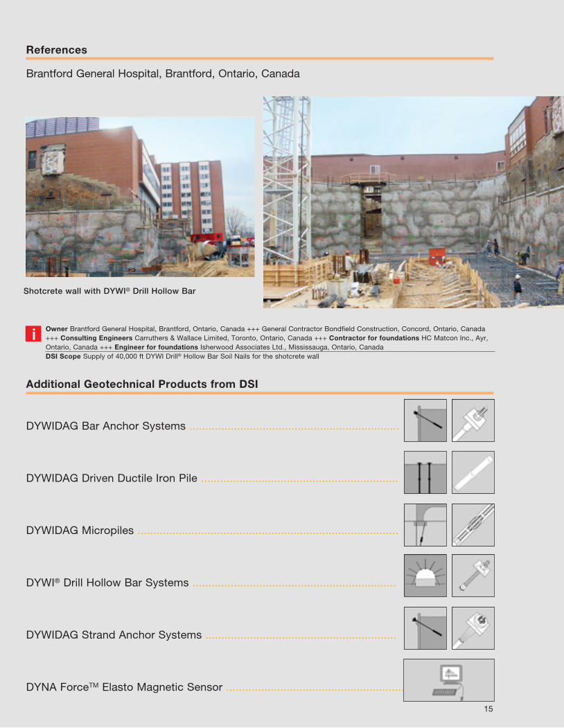
Owner City of Reno, Nevada, NV, USA +++ General Contractor Granite Construction, CA, USA +++ Design Team Leader Parsons, CA, USA +++ Project Management Jacobs Engineering Group, CA, USA +++ SubContractor (Shoring Contractor) Schnabel Foundation Co., CA, USADSI Scope Supply of more than 8,000 R38 DYWI® Drill Hollow Bars supporting 180,000 SF of soil nail wall
i
Reno ReTRAC (Reno Transportation Rail Access Corridor), Reno, NV
14
References
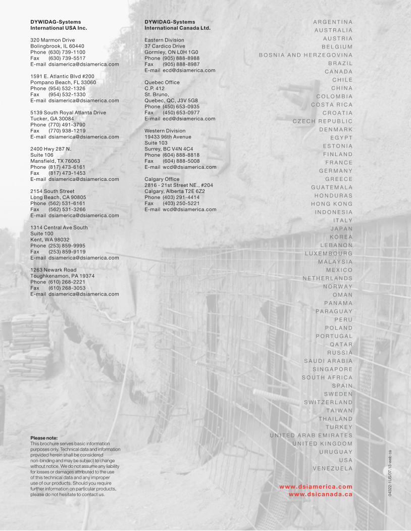
Brantford General Hospital, Brantford, Ontario, Canada
DYWIDAG Bar Anchor Systems ..................................................................
DYWIDAG Driven Ductile Iron Pile ..............................................................
DYWIDAG Micropiles ..................................................................................
DYWI® Drill Hollow Bar Systems ................................................................
DYWIDAG Strand Anchor Systems ............................................................
DYNA ForceTM Elasto Magnetic Sensor .........................................................
Additional Geotechnical Products from DSI
Owner Brantford General Hospital, Brantford, Ontario, Canada +++ General Contractor Bondfield Construction, Concord, Ontario, Canada +++ Consulting Engineers Carruthers & Wallace Limited, Toronto, Ontario, Canada +++ Contractor for foundations HC Matcon Inc., Ayr, Ontario, Canada +++ Engineer for foundations Isherwood Associates Ltd., Mississauga, Ontario, CanadaDSI Scope Supply of 40,000 ft DYWI Drill® Hollow Bar Soil Nails for the shotcrete wall
i
Shotcrete wall with DYWI® Drill Hollow Bar
15
0432
2-1U
S/0
7.13
-web
ca
A R G E N T I N A
A U S T R A L I A
A U S T R I A
B E L G I U M
B O S N I A A N D H E R Z E G O V I N A
B R A Z I L
C A N A D A
C H I L E
C H I N A
C O L O M B I A
C O S T A R I C A
C R O A T I A
C Z E C H R E P U B L I C
D E N M A R K
E G Y P T
E S T O N I A
F I N L A N D
F R A N C E
G E R M A N Y
G R E E C E
G U A T E M A L A
H O N D U R A S
H O N G K O N G
I N D O N E S I A
I T A L Y
J A P A N
K O R E A
L E B A N O N
L U X E M B O U R G
M A L A Y S I A
M E X I C O
N E T H E R L A N D S
N O R W A Y
O M A N
P A N A M A
P A R A G U A Y
P E R U
P O L A N D
P O R T U G A L
Q A T A R
R U S S I A
S A U D I A R A B I A
S I N G A P O R E
S O U T H A F R I C A
S P A I N
S W E D E N
S W I T Z E R L A N D
T A I W A N
T H A I L A N D
T U R K E Y
U N I T E D A R A B E M I R A T E S
U N I T E D K I N G D O M
U R U G U A Y
U S A
V E N E Z U E L A
www.dsiamerica.comwww.dsicanada.ca
DYWIDAG-SystemsInternational USA Inc.
320 Marmon DriveBolingbrook, IL 60440Phone (630) 739-1100Fax (630) 739-5517E-mail [email protected]
1591 E. Atlantic Blvd #200Pompano Beach, FL 33060Phone (954) 532-1326Fax (954) 532-1330E-mail [email protected]
5139 South Royal Atlanta DriveTucker, GA 30084Phone (770) 491-3790Fax (770) 938-1219E-mail [email protected]
2400 Hwy 287 N.Suite 106Mansfield, TX 76063Phone (817) 473-6161Fax (817) 473-1453E-mail [email protected]
2154 South StreetLong Beach, CA 90805Phone (562) 531-6161Fax (562) 531-3266E-mail [email protected]
1314 Central Ave SouthSuite 100Kent, WA 98032Phone (253) 859-9995Fax (253) 859-9119E-mail [email protected]
1263 Newark RoadToughkenamon, PA 19374Phone (610) 268-2221Fax (610) 268-3053E-mail [email protected]
DYWIDAG-SystemsInternational Canada Ltd.
Eastern Division37 Cardico DriveGormley, ON L0H 1G0Phone (905) 888-8988Fax (905) 888-8987E-mail [email protected]
Quebec OfficeC.P. 412St. Bruno, Quebec, QC, J3V 5G8Phone (450) 653-0935Fax (450) 653-0977E-mail [email protected]
Western Division19433 96th AvenueSuite 103Surrey, BC V4N 4C4Phone (604) 888-8818Fax (604) 888-5008E-mail [email protected]
Calgary Office2816 - 21st Street NE., #204Calgary, Alberta T2E 6Z2Phone (403) 291-4414Fax (403) 250-5221E-mail [email protected]
Please note: This brochure serves basic information purposes only. Technical data and information provided herein shall be considered non-binding and may be subject to change without notice. We do not assume any liability for losses or damages attributed to the use of this technical data and any improper use of our products. Should you require further information on particular products, please do not hesitate to contact us.