Embed Size (px)
Citation preview
DYWIDAG Reinforcement Systems
GEWI® Coupler Splices40 and 50 mm
Coupler connections and ancho-ring of reinforcing bars with thread ribs BST 500 S- GEWI® ø 40 and 50 mm
Approval NumberZ-1.5-149Validity: 01 Dezember 1976 - 30 September 2010
D E U T S C H E S I N S T I T U T F Ü R B A U T E C H N I K Statutory Body
10829 Berlin, 29 September 2005 Kolonnenstrasse 30 L Tel.: 030 78730-267 Fax: 030 78730-320 Ref. No.: I 18-1.1.5-11/05
General Construction Supervisory Authority Approval
Approval No.: Z-1.5-149
Applicant: DYWIDAG-Systems International GmbH Dywidagstrasse 1 85609 Aschheim
Subject of Approval: Coupler connections and anchoring of reinforcing bars with thread ribs BSt 500 S–GEWI nominal diameters: 40 and 50 mm
Valid until: 30 September 2010
The above-mentioned subject of the approval is herewith granted a general construction supervisory authority approval.* This general construction supervisory authority approval consists of nine pages and 15 appendices. Important Notice
This general construction supervisory authority approval is the translation of a document originally prepared in the German language which has not been verified and officially authorised by the “Deutsches Institut für Bautechnik“ (DIBt; German Institute for Building Technology). In case of doubt in respect to wording and/or interpretation of this approval, the original German version of this document shall prevail exclusively. No liability is therefore assumed for translation errors or inaccuracies.
------------------------------------------ *This general construction supervisory authority approval supersedes the general construction supervisory authority approval No. Z-1.5-149 of 31 May 2000. The subject of approval was granted a general construction supervisory authority approval on 1 December 1976 for the very first time.
Page 2 of the General Construction Supervisory Authority Approval No. Z-1.5-149 of 29 September 2005
I. GENERAL PROVISIONS
1 This general construction supervisory authority approval verifies the suitability (fitness for the intended purpose) of the subject of the approval in keeping with the state construction ordinances.
2 The general construction supervisory authority approval does not replace the permissions,
agreements and certifications required by law for a construction project to be carried out. 3 The general construction supervisory authority approval is granted without prejudicing the
rights of third parties, especially private protection rights. 4 Notwithstanding any further regulations in the "Special Provisions" section, the
manufacturer and distributor of the subject of approval shall provide the user with copies of the certificate of approval; furthermore, they shall inform the user that the certificate of approval must be available at the place of use. Copies of the general construction supervisory authority approval must be made available to involved authorities on request.
5 The general construction supervisory authority approval may only be copied completely.
The publication of extracts is subject to approval by the DIBt. Texts and drawings of advertising material may not contradict the general construction supervisory authority approval. Translations of the general construction supervisory authority approval must contain the note 'Translation of the German original which has not been checked by the DIBt".
6 The general construction supervisory authority approval is granted, but is revocable. The
provisions in the general construction supervisory authority approval can be subsequently supplemented or changed, especially if the latest technical findings give reason for this.
Page 3 of the General Construction Supervisory Authority Approval No. Z-1.5-149 of 29 September 2005
II. SPECIAL PROVISIONS 1 Subject of approval, and applications
1.1 Subject of approval
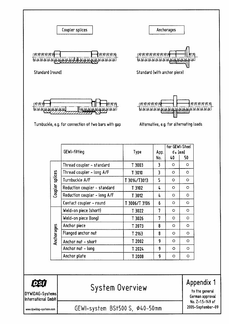
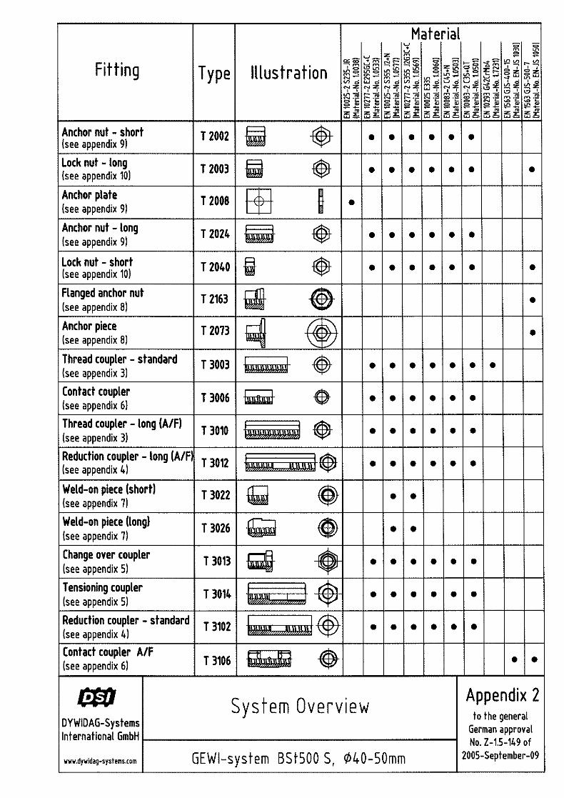
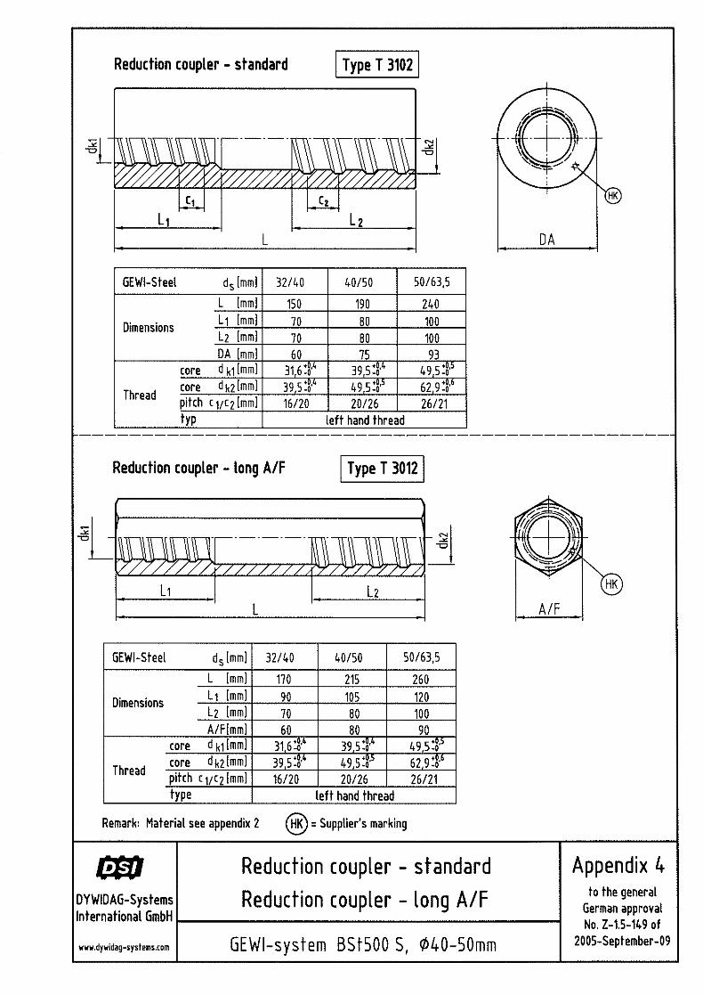
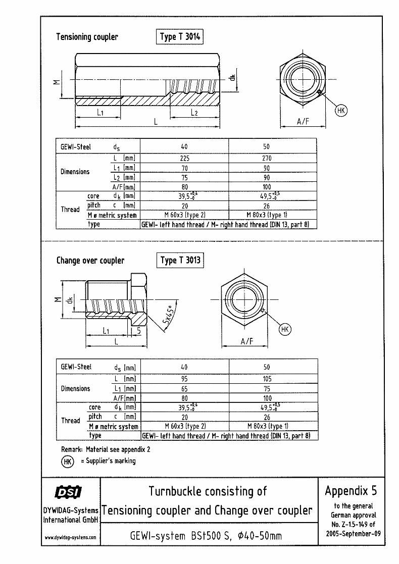
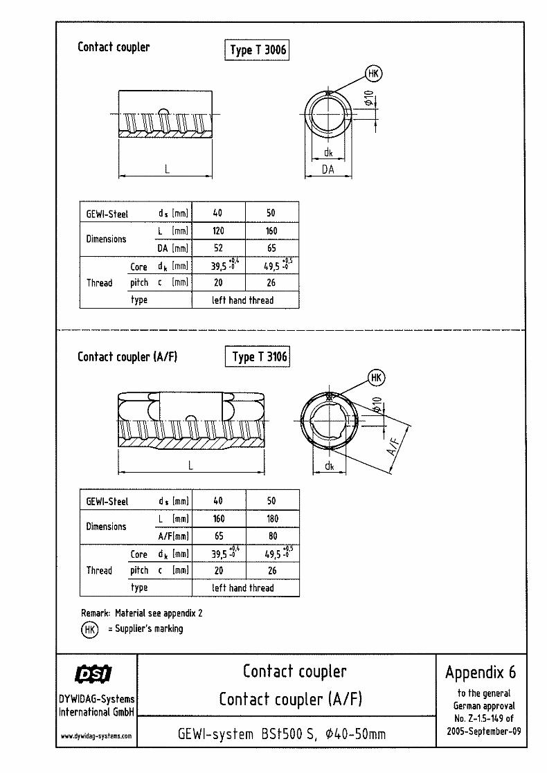
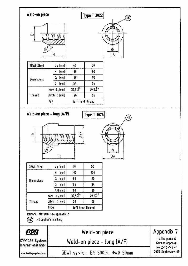
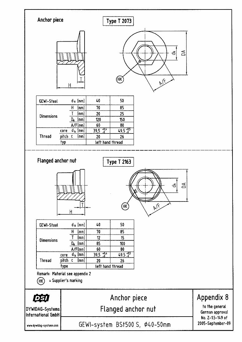
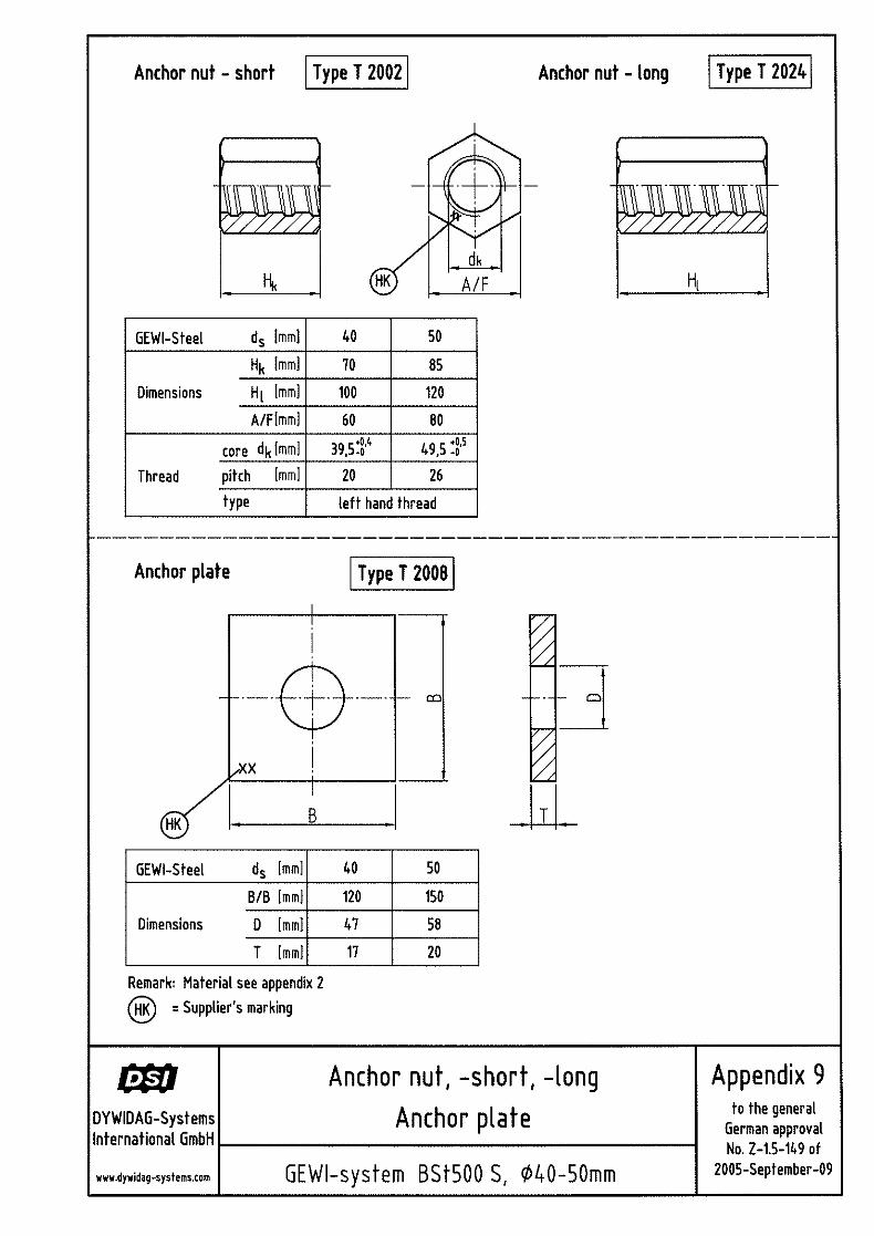
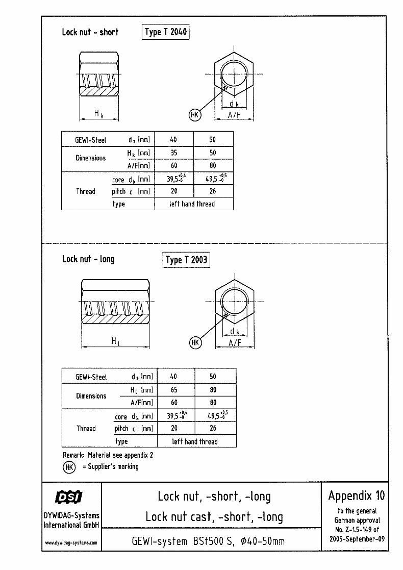
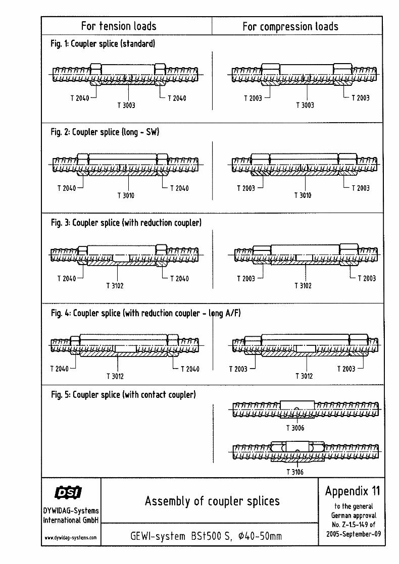
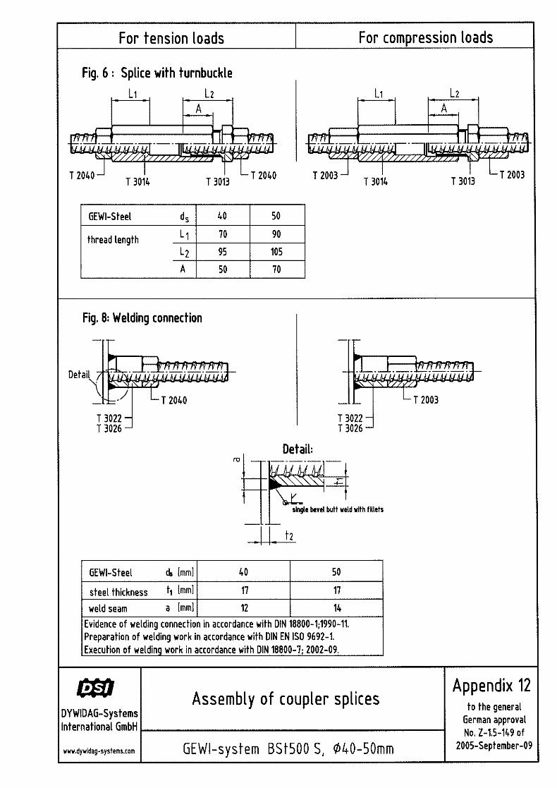
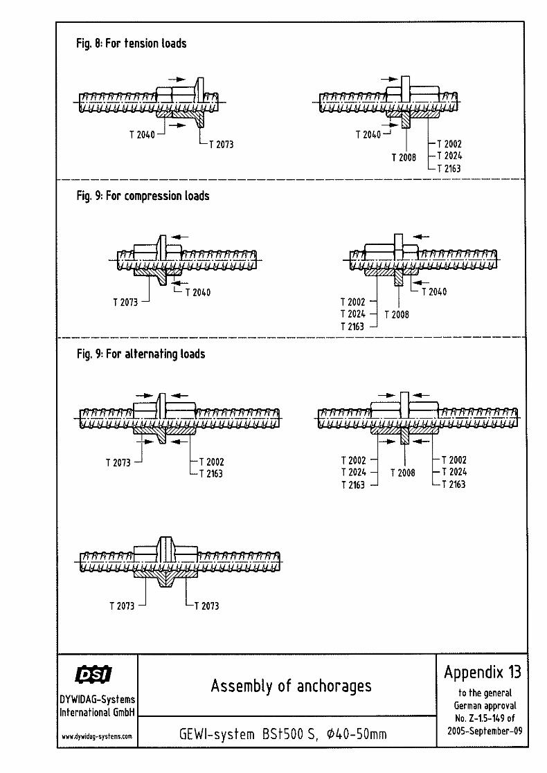
(1) Object of this approval are mechanical couplings and anchorages of reinforcing steel with thread ribs by means of screwed couplers or screwed-on anchoring components (see Appendix 1). (2) The diameters of the reinforcing steel with thread ribs BSt 500 S-GEWI (GEWI Threadbar) are 40 and 50 mm. A general construction supervisory authority approval is required for the reinforcing steel. (3) The coupling and anchoring components have an internal thread into which the threadbars are screwed in. Slip-reducing fastening of threads is achieved by a torque either applied to the lock nuts (T 2040, T 2003) or directly to the threadbars. (4) Standard couplers (T 3003) und long couplers (T 3010) are used to form tension and compression splices of threadbars having identical diameters. (5) Reducing couplers (T 3102) serve for coupling bars with diameters 32/40, 40/50 and 50/63.5 mm. (6) Tunrnbuckles (T 3014/T 3013) are used when the GEWI Threadbars to be connected are immovable and non rotatable. Free movement of the bar threads is synchronised by means of a change-over coupler (T 3013) that has a metric thread outside and a GEWI thread inside to receive the connecting bar. (7) Contact couplers (T 3006/T 3106) are used to form sheer compression splices. The coupler secures the centrical position of the bars whose end faces are pressed onto each other by a defined torque. (8) GEWI Threadbars are anchored by means of anchor pieces (T 2073) or anchor plates (T 2008) that are fastened with the thread of the bar via anchor nuts (T 2163 or T 2002). (9) Weld-on pieces (T 3022 or T 3026) suited for welding that are welded on with a fillet weld placed along the periphery serve to transfer axial tensile and compressive loads from the GEWI Threadbar to a steel component.
1.2 Applications The object of the approval serves for anchoring and splicing threadbars BSt 500 S-GEWI either in accordance with DIN 1045:1988-07 "Concrete and reinforced concrete", Sections 18.5 and 18.6 or in accordance with DIN 1045-1:2001-07 "Concrete, reinforced and prestressed concrete structures, Part 1: Design", Sections 12.6 and 12.8.
2 Regulations covering the construction product
2.1 Features and constituents 2.1.1 Material properties
The raw material for the coupling and anchoring components is specified in Appendix 2. The requirements for the material properties specified in the standards indicated therein shall be met.
Page 4 of the General Construction Supervisory Authority Approval No. Z-1.5-149 of 29 September 2005
2.1.2 Geometry The specifications provided in Appendices 3 to 10 shall apply to the outer dimensions of the coupling and anchoring components as well as to the geometry of the threads to be observed. The shop drawings including the indicated tolerances are deposited with the DIBt and the external surveillance authority.
2.2 Manufacture, packaging, transport, storage and marking 2.2.1 Manufacture
Depending on the material used (see Appendix 2), the coupling and anchoring components are either cast into their final form or cut as blanks from the bar stock into sections, drilled and provided with a cut interior thread analogous to the GEWI Threadbar at the plant.
2.2.2 Packaging, transport and storage The coupling and anchoring components shall be packed, transported and stored so that they are protected from corrosion, mechanical damage and dirt accumulation prior to their use on the construction site.
2.2.3 Marking (1) The couplers, anchoring components and lock nuts shall be provided with the manufacturer's mark at the positions specified in the relevant appendices. (2) The manufacturer shall mark the delivery note for coupling and anchoring components with the compliance mark pursuant to the compliance mark regulations issued by the German States. This mark may only be affixed if all requirements of the compliance certificate pursuant to Section 2.3 have fully been met.
2.3 Compliance certificate 2.3.1 General points
(1) Every plant must comply with the following provisions to confirm compliance of the coupling and anchoring components on the basis of a factory production control and regular external surveillance including initial inspection with the provisions of this general construction supervisory authority approval. (2) The manufacturer of the coupling and anchoring components shall commission a recognised certification authority and a recognised inspection agency to issue the certificate of compliance and conduct external surveillance including the inspection of products. (3) An initial inspection shall be conducted in accordance with the inspection and testing plan filed with the DIBt. (4) The certification authority shall submit a copy of the certificate of compliance issued to DIBt and inform DIBt about the results of the initial inspection.
2.3.2 Factory production control (1) Each plant must set up and also carry out its own factory production control. Factory production control is understood to be the continual monitoring of production by the manufacturer who thus ensures that the construction products manufactured by him meet the requirements of this general construction supervisory authority approval. (2) The factory production control must include at least the measures specified in the "Approval principles for mechanical connections and anchorages of reinforcing steel" in the edition of November 1993. (3) Evidence of the material properties of the raw material for the coupling and anchoring components shall be produced by inspection certificate "3.1" in accordance with DIN EN 10204:2005-01.
Page 5 of the General Construction Supervisory Authority Approval No. Z-1.5-149 of 29 September 2005
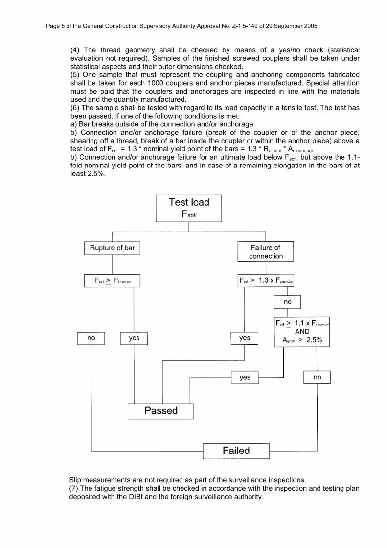
(4) The thread geometry shall be checked by means of a yes/no check (statistical evaluation not required). Samples of the finished screwed couplers shall be taken under statistical aspects and their outer dimensions checked. (5) One sample that must represent the coupling and anchoring components fabricated shall be taken for each 1000 couplers and anchor pieces manufactured. Special attention must be paid that the couplers and anchorages are inspected in line with the materials used and the quantity manufactured. (6) The sample shall be tested with regard to its load capacity in a tensile test. The test has been passed, if one of the following conditions is met: a) Bar breaks outside of the connection and/or anchorage.
b) Connection and/or anchorage failure (break of the coupler or of the anchor piece, shearing off a thread, break of a bar inside the coupler or within the anchor piece) above a test load of Fsoll = 1.3 * nominal yield point of the bars = 1.3 * Re,nom * As,nom,bar b) Connection and/or anchorage failure for an ultimate load below Fsoll, but above the 1.1-fold nominal yield point of the bars, and in case of a remaining elongation in the bars of at least 2.5%.
Slip measurements are not required as part of the surveillance inspections. (7) The fatigue strength shall be checked in accordance with the inspection and testing plan deposited with the DIBt and the foreign surveillance authority.
Page 6 of the General Construction Supervisory Authority Approval No. Z-1.5-149 of 29 September 2005
(8) The results of factory production control shall be recorded and evaluated. The records shall include at least: - Designation of the construction product and/or the raw material and the components. - Type of control or testing. - Date of manufacture and inspection / testing of the construction product and/or the
raw material or the components. - Results of controls and inspections and, if applicable, comparison with the
requirements. - Signature of the person in charge of the factory production control. (9) The records must be filed for at least five years and presented to the inspection agency commissioned with external surveillance. On request, they must be submitted to the DIBt and the highest construction supervisory authority responsible. (10) If the inspection results are unsatisfactory, the manufacturer shall immediately take the necessary actions to eliminate the problem. Construction products which do not meet requirements must be treated so that they cannot be mixed up with complying products. Once the problem has been eliminated, the relevant inspection must be repeated immediately, provided that this is technically feasible and also required, to verify elimination of the problem.
2.3.3 External surveillance (1) In each production plant, external surveillance must be set up and implemented regularly, but at least twice a year, to check the plant’s factory production control in accordance with the principles specified under Section 2.3.2 (2). (2) As part of the external surveillance, samples for testing must be taken. Sampling and testing are incumbent on the respective recognised inspection agency. (3) The results of the certification and of external surveillance shall be kept for at least five years. On request, they must be presented to the DIBt and to the highest construction supervisory authority by the certification authority and the surveillance authority.
3 Regulations covering design and dimensions
3.1 General points (1) Unless stated otherwise hereinafter, either DIN 1045:1988-07 or DIN 1045-1:2001-07 shall apply to design and dimensions. (2) All bars in one section may be spliced (full splice). (3) The position and dimension of the coupler splices and anchorages must be plotted in the reinforcement drawings, and the prerequisites specified in the installation regulations must be fulfilled.
3.2 Permissible load 3.2.1 Predominantly dead load
Splices and anchorages as per this general construction supervisory authority approval may be loaded 100% like an unspliced bar in case of predominantly dead tensile and compressive loads.
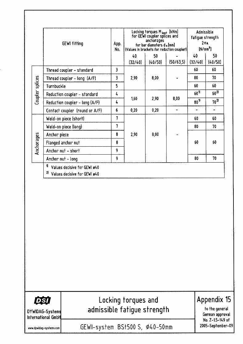
3.2.2 Not predominantly dead load (1) If designed in line with DIN 1045:1988-07, fatigue stress ranges of 2 * σA of the steel stresses are permissible in the spliced or anchored section of the reinforcement as specified in Appendix 15, Table 1.
Page 7 of the General Construction Supervisory Authority Approval No. Z-1.5-149 of 29 September 2005
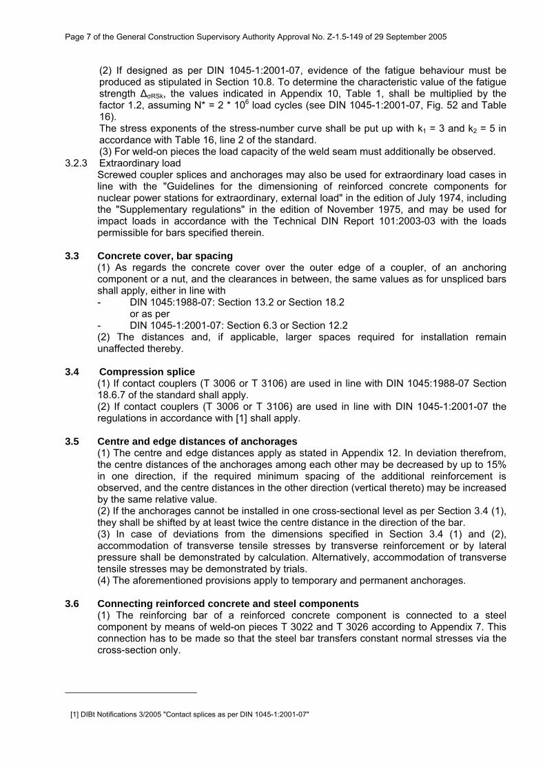
(2) If designed as per DIN 1045-1:2001-07, evidence of the fatigue behaviour must be produced as stipulated in Section 10.8. To determine the characteristic value of the fatigue strength ΔσRSk, the values indicated in Appendix 10, Table 1, shall be multiplied by the factor 1.2, assuming N* = 2 * 106 load cycles (see DIN 1045-1:2001-07, Fig. 52 and Table 16). The stress exponents of the stress-number curve shall be put up with k1 = 3 and k2 = 5 in accordance with Table 16, line 2 of the standard. (3) For weld-on pieces the load capacity of the weld seam must additionally be observed.
3.2.3 Extraordinary load Screwed coupler splices and anchorages may also be used for extraordinary load cases in line with the "Guidelines for the dimensioning of reinforced concrete components for nuclear power stations for extraordinary, external load" in the edition of July 1974, including the "Supplementary regulations" in the edition of November 1975, and may be used for impact loads in accordance with the Technical DIN Report 101:2003-03 with the loads permissible for bars specified therein.
3.3 Concrete cover, bar spacing (1) As regards the concrete cover over the outer edge of a coupler, of an anchoring component or a nut, and the clearances in between, the same values as for unspliced bars shall apply, either in line with - DIN 1045:1988-07: Section 13.2 or Section 18.2
or as per - DIN 1045-1:2001-07: Section 6.3 or Section 12.2 (2) The distances and, if applicable, larger spaces required for installation remain unaffected thereby.
3.4 Compression splice (1) If contact couplers (T 3006 or T 3106) are used in line with DIN 1045:1988-07 Section 18.6.7 of the standard shall apply. (2) If contact couplers (T 3006 or T 3106) are used in line with DIN 1045-1:2001-07 the regulations in accordance with [1]1shall apply.
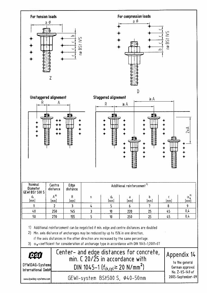
3.5 Centre and edge distances of anchorages (1) The centre and edge distances apply as stated in Appendix 12. In deviation therefrom, the centre distances of the anchorages among each other may be decreased by up to 15% in one direction, if the required minimum spacing of the additional reinforcement is observed, and the centre distances in the other direction (vertical thereto) may be increased by the same relative value. (2) If the anchorages cannot be installed in one cross-sectional level as per Section 3.4 (1), they shall be shifted by at least twice the centre distance in the direction of the bar. (3) In case of deviations from the dimensions specified in Section 3.4 (1) and (2), accommodation of transverse tensile stresses by transverse reinforcement or by lateral pressure shall be demonstrated by calculation. Alternatively, accommodation of transverse tensile stresses may be demonstrated by trials. (4) The aforementioned provisions apply to temporary and permanent anchorages.
3.6 Connecting reinforced concrete and steel components (1) The reinforcing bar of a reinforced concrete component is connected to a steel component by means of weld-on pieces T 3022 and T 3026 according to Appendix 7. This connection has to be made so that the steel bar transfers constant normal stresses via the cross-section only.
1 [1] DIBt Notifications 3/2005 "Contact splices as per DIN 1045-1:2001-07"
Page 8 of the General Construction Supervisory Authority Approval No. Z-1.5-149 of 29 September 2005
(2) Steel component, weld-on piece and lock nut shall be protected against corrosion in line with the provisions applicable to the specific use case [2]2.
3.7 Bending
(1) The regular bending of a bar may only start in a distance of at least 5 * ds from the end of the coupler (ds = nominal diameter of the bent bar). (2) If coupler bars are bent with special equipment at the plant, the distabce to the coupler end may be decreased up to 2 * ds.
4. Regulations for work execution 4.1 General
(1) Only components marked as per Section 2.2.3 may be used. (2) To torque the screwed coupler connections and anchorages only torque equipment may be used that has been checked with regard to operability and accuracy, that enables reliable reading of the required torque moment Mkont or switches off if the torque moment set has been achieved. Deviation for the setting and reading or switching off operation may be no more than +0,4 Mkont and -0,1 Mkont. (3) The force of the torque to be applied is specified by Appendix 15. (4) The coupler connections and anchorages may only be made by trained personnel. Therefore the manufacturer shall provide written work instructions. (5) The dimensions of the coupling and anchoring components, especially the length of nuts and their arrangement, must comply with the engineering drawings (reinforcement drawings). (6) The threads of bars, coupling and anchoring components must be free of rust and dirt accumulations.
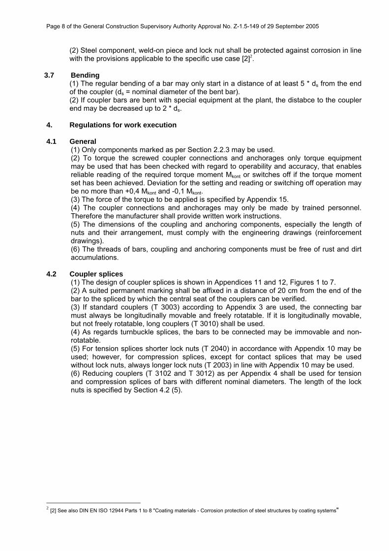
4.2 Coupler splices (1) The design of coupler splices is shown in Appendices 11 and 12, Figures 1 to 7. (2) A suited permanent marking shall be affixed in a distance of 20 cm from the end of the bar to the spliced by which the central seat of the couplers can be verified. (3) If standard couplers (T 3003) according to Appendix 3 are used, the connecting bar must always be longitudinally movable and freely rotatable. If it is longitudinally movable, but not freely rotatable, long couplers (T 3010) shall be used. (4) As regards turnbuckle splices, the bars to be connected may be immovable and non-rotatable. (5) For tension splices shorter lock nuts (T 2040) in accordance with Appendix 10 may be used; however, for compression splices, except for contact splices that may be used without lock nuts, always longer lock nuts (T 2003) in line with Appendix 10 may be used. (6) Reducing couplers (T 3102 and T 3012) as per Appendix 4 shall be used for tension and compression splices of bars with different nominal diameters. The length of the lock nuts is specified by Section 4.2 (5).
2 [2] See also DIN EN ISO 12944 Parts 1 to 8 "Coating materials - Corrosion protection of steel structures by coating systems"
Page 9 of the General Construction Supervisory Authority Approval No. Z-1.5-149 of 29 September 2005
4.3 Anchorages (1) For exclusive tensile or compressive load, the anchorage either consists of an anchor nut (T 2002, T 2024 or T 2024) and a lock nut (T 2040) with an anchor plate (T 2008) in between or of an anchor piece (T 2073) with lock nut (T 2040) (see Appendix 13). (2) For alternating loads (tensile and compressive loads), the anchorage either consists of two anchor nuts (T 2002, T 2024 or T 2024) with an anchor plate (T 2008) in between or of an anchor piece (T 2073) with anchor nut (T 2002, T 2024 or T 2024) (see Appendix 13). (3) The strength class of the concrete for the anchorage must be at least C 20/25 (fck ≥ 20 N/mm2) or B 25.
4.4 Weld-on pieces (1) To connect weld-on pieces T 3022 and T 3026 as per Appendix 7 to a steel component, recognised WPS welding instructions in accordance with DIN EN 288-2:1997-10 must be available that must be observed by the welding personnel. (2) Weld-on pieces may be torqued with short nuts (T 2040) in case of tensile load, and must be secured with long nuts (T 2003), see Appendix 10, in case of compressive load.
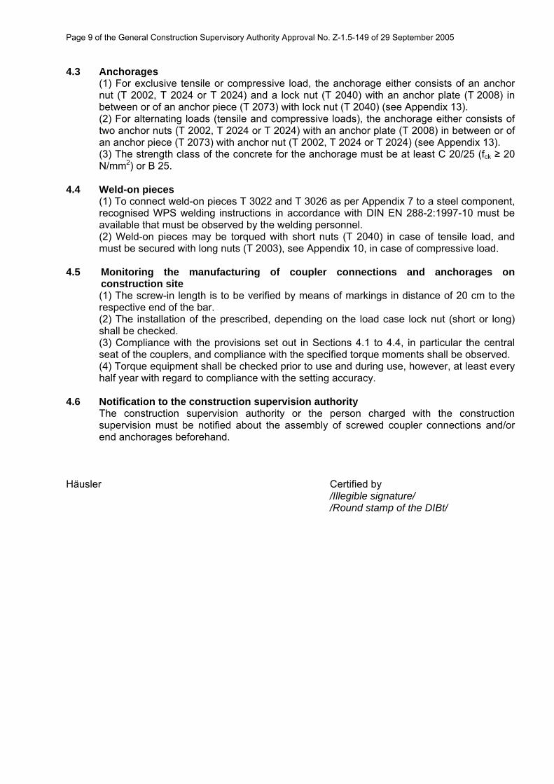
4.5 Monitoring the manufacturing of coupler connections and anchorages on construction site (1) The screw-in length is to be verified by means of markings in distance of 20 cm to the respective end of the bar. (2) The installation of the prescribed, depending on the load case lock nut (short or long) shall be checked. (3) Compliance with the provisions set out in Sections 4.1 to 4.4, in particular the central seat of the couplers, and compliance with the specified torque moments shall be observed. (4) Torque equipment shall be checked prior to use and during use, however, at least every half year with regard to compliance with the setting accuracy.
4.6 Notification to the construction supervision authority The construction supervision authority or the person charged with the construction supervision must be notified about the assembly of screwed coupler connections and/or end anchorages beforehand.
Häusler Certified by /Illegible signature/ /Round stamp of the DIBt/

A u s t r i A
A r g e n t i n A
A u s t r A l i A
b e l g i u m
b o s n i A A n d h e r z e g o v i n A
b r A z i l
C A n A d A
C h i l e
C o l o m b i A
C o s t A r i C A
C r o A t i A
C z e C h r e p u b l i C
d e n m A r k
e g y p t
e s t o n i A
F i n l A n d
F r A n C e
g e r m A n y
g r e e C e
g u A t e m A l A
h o n d u r A s
h o n g k o n g
i n d o n e s i A
i r A n
i t A l y
J A p A n
k o r e A
l e b A n o n
l u x e m b o u r g
m A l A y s i A
m e x i C o
n e t h e r l A n d s
n o r w A y
o m A n
p A n A m A
p A r A g u A y
p e r u
p o l A n d
p o r t u g A l
Q A t A r
s A u d i A r A b i A
s i n g A p o r e
s o u t h A F r i C A
s p A i n
s w e d e n
s w i t z e r l A n d
t A i w A n
t h A i l A n d
t u r k e y
u n i t e d A r A b e m i r A t e s
u n i t e d k i n g d o m
u r u g u A y
u s A
v e n e z u e l A
www.dywidag-systems.com
AustriadywidAg-systemsinternAtionAl gmbhwagram 494061 pasching/linz, Austriaphone +43-7229-61 04 90Fax +43-7229-61 04 980 e-mail: [email protected]
dywidAg-systemsinternAtionAl gmbhteichweg 95400 hallein, Austriaphone +43-6245-87 23 0 Fax +43-6245-87 23 08 0e-mail: [email protected]
Belgium and LuxembourgdywidAg-systemsinternAtionAl n.v.industrieweg 253190 boortmeerbeek, belgiumphone +32-16-60 77 60Fax +32-16-60 77 66e-mail: [email protected]
Francedsi-ArtéonAvenue du bicentenairezi dagneux-bp 5005301122 montluel Cedex, Francephone +33-4-78 79 27 82Fax +33-4-78 79 01 56e-mail: [email protected]
GermanydywidAg-systemsinternAtionAl gmbhschuetzenstrasse 2014641 nauen, germanyphone +49 3321 44 18 32Fax +49 3321 44 18 18e-mail: [email protected]
dywidAg-systemsinternAtionAl gmbhmax-planck-ring 140764 langenfeld, germanyphone +49 2173 79 02 0Fax +49 2173 79 02 20e-mail: [email protected]
dywidAg-systemsinternAtionAl gmbhgermanenstrasse 886343 koenigsbrunn, germanyphone +49 8231 96 07 0Fax +49 8231 96 07 40e-mail: [email protected]
dywidAg-systems internAtionAl gmbhsiemensstrasse 885716 unterschleissheim, germanyphone +49-89-30 90 50-100Fax +49-89-30 90 50-120e-mail: [email protected]
Italydywit s.p.A.via grandi, 6820017 mazzo di rho (milano), italyphone +39-02-93 46 87 1Fax +39-02-93 46 87 301e-mail: [email protected]
NetherlandsdywidAg-systemsinternAtionAl b.vveilingweg 25301 km zaltbommel, netherlandsphone +31-418-57 89 22Fax +31-418-51 30 12e-mail: [email protected]
NorwaydywidAg-systemsinternAtionAl A/sindustrieveien 7A1483 skytta, norwayphone +47-67-06 15 60Fax +47-67-06 15 59e-mail: [email protected]
PortugaldywidAg-systemsinternAtionAl ldArua do polo sullote 1.01.1.1 – 2b1990-273 lisbon, portugalphone +351-21-89 22 890Fax +351-21-89 22 899e-mail: [email protected]
SpaindywidAg sistemAs ConstruCtivos, s.A.Avenida de la industria, 4pol. ind. la Cantuena28947 Fuenlabrada (mAdrid), spainphone +34-91-642 20 72Fax +34-91-642 27 10e-mail: dywidag @dywidag-sistemas.comwww.dywidag-sistemas.com
United KingdomdywidAg-systemsinternAtionAl ltd.Northfield Roadsoutham, warwickshireCv47 0Fg, great britainphone +44-1926-81 39 80Fax +44-1926-81 38 17e-mail: [email protected]/uk