Embed Size (px)
Citation preview
HAL Id: hal-01807189https://hal.archives-ouvertes.fr/hal-01807189
Submitted on 19 Jun 2018
HAL is a multi-disciplinary open accessarchive for the deposit and dissemination of sci-entific research documents, whether they are pub-lished or not. The documents may come fromteaching and research institutions in France orabroad, or from public or private research centers.
L’archive ouverte pluridisciplinaire HAL, estdestinée au dépôt et à la diffusion de documentsscientifiques de niveau recherche, publiés ou non,émanant des établissements d’enseignement et derecherche français ou étrangers, des laboratoirespublics ou privés.
Dynamic Model of a Bio-Inspired Robot for PipingInspection
Damien Chablat, Swaminath Venkateswaran, Frédéric Boyer
To cite this version:Damien Chablat, Swaminath Venkateswaran, Frédéric Boyer. Dynamic Model of a Bio-Inspired Robotfor Piping Inspection. Vigen Arakelian, Philippe Wenger. ROMANSY 22 – Robot Design, Dynamicsand Control, 584, Springer, Cham, pp.42-51, 2018, CISM International Centre for Mechanical Sciences(Courses and Lectures), 978-3-319-78962-0. �10.1007/978-3-319-78963-7_7�. �hal-01807189�
Dynamic Model of a Bio-Inspired Robotfor Piping Inspection
Damien Chablat1(B), Swaminath Venkateswaran2, and Frederic Boyer3
1 CNRS, Laboratoire des Sciences du Numerique de Nantes, UMR CNRS 6004,1 rue de la Noe, 44321 Nantes, France
[email protected] Ecole Centrale de Nantes, Laboratoire des Sciences du Numerique de Nantes,
UMR CNRS 6004, 1 rue de la Noe, 44321 Nantes, France3 IMT Atlantique, Laboratoire des Sciences du Numerique de Nantes,
UMR CNRS 6004, 4 rue Alfred Kastler La Chantrerie, 44307 Nantes, France
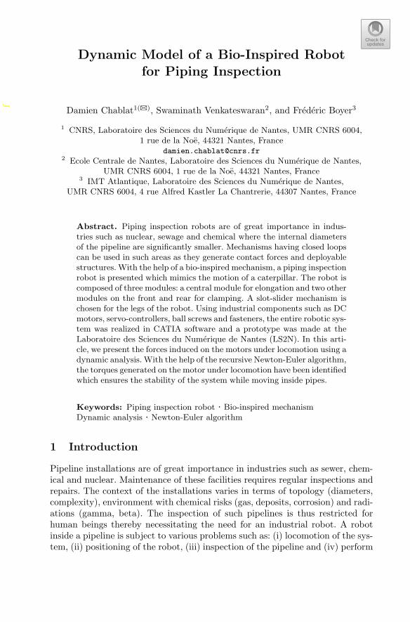
Abstract. Piping inspection robots are of great importance in indus-tries such as nuclear, sewage and chemical where the internal diametersof the pipeline are significantly smaller. Mechanisms having closed loopscan be used in such areas as they generate contact forces and deployablestructures. With the help of a bio-inspired mechanism, a piping inspectionrobot is presented which mimics the motion of a caterpillar. The robot iscomposed of three modules: a central module for elongation and two othermodules on the front and rear for clamping. A slot-slider mechanism ischosen for the legs of the robot. Using industrial components such as DCmotors, servo-controllers, ball screws and fasteners, the entire robotic sys-tem was realized in CATIA software and a prototype was made at theLaboratoire des Sciences du Numerique de Nantes (LS2N). In this arti-cle, we present the forces induced on the motors under locomotion using adynamic analysis. With the help of the recursive Newton-Euler algorithm,the torques generated on the motor under locomotion have been identifiedwhich ensures the stability of the system while moving inside pipes.
Keywords: Piping inspection robot · Bio-inspired mechanismDynamic analysis · Newton-Euler algorithm
1 Introduction
Pipeline installations are of great importance in industries such as sewer, chem-ical and nuclear. Maintenance of these facilities requires regular inspections andrepairs. The context of the installations varies in terms of topology (diameters,complexity), environment with chemical risks (gas, deposits, corrosion) and radi-ations (gamma, beta). The inspection of such pipelines is thus restricted forhuman beings thereby necessitating the need for an industrial robot. A robotinside a pipeline is subject to various problems such as: (i) locomotion of the sys-tem, (ii) positioning of the robot, (iii) inspection of the pipeline and (iv) perform
c© CISM International Centre for Mechanical Sciences 2019V. Arakelian and P. Wenger (Eds.): ROMANSY 22 - Robot Design,Dynamics and Control, pp. 1–10, 2019.https://doi.org/10.1007/978-3-319-78963-7_7
f
2 D. Chablat et al.
mechanical tasks (welding, cleaning etc.). In order to simplify the robot design,there are methods to facilitate the choice of the robot’s different elements, suchas the paw mechanism for managing the contact forces between the robot andthe environment. We can distinguish two types of robot family according to theirlocomotion namely mechanical and bio-inspired systems. A distinction betweenthe two categories was proposed by Kassim et al. [1]. A bio-inspired mechanicalsystem that mimics the motion of a caterpillar has been presented by Henry1
et al. [2]. The robot has two leg mechanisms for contact points with the walls of apipe and a central system for elongation. The study of forces and torques on themotor were not done in detail which is very essential to understand the robust-ness of the system under various inclinations and obstacles within the pipeline.Thus, in this article the force analysis on the robot during locomotion using adynamic model has been presented. The outline of the article is as follows. Thelocomotion principle as well as the architecture of the bio-inspired robot is pre-sented. Followed by that, the Newton-Euler algorithm for the dynamic analysisand the results of dynamic forces under locomotion are presented. The articlethen ends with closing conclusions.
2 Locomotion and Architecture of the Robot
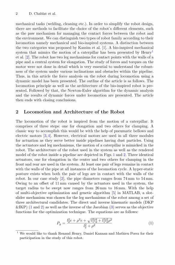
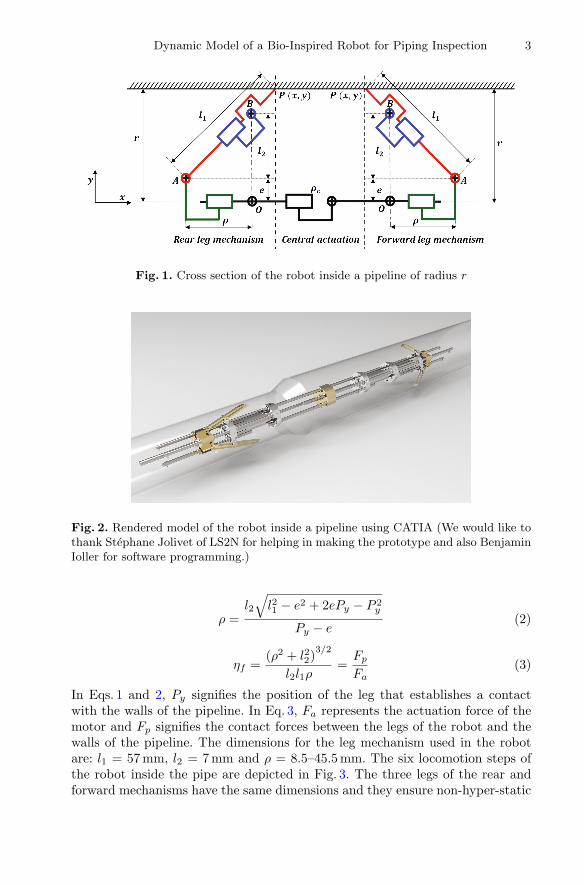
The locomotion of the robot is inspired from the motion of a caterpillar. Itcomprises of three steps: one for elongation and two others for clamping. Aclassic way to accomplish this would be with the help of pneumatic bellows andelectric motors [3,4]. However, electrical motors are used in all three modulesfor actuation as they serve better inside pipelines having dust particles. Usingthe actuators and leg mechanisms, the motion of a caterpillar is mimicked in therobot. The architecture of the robot used in the system as well as the renderedmodel of the robot inside a pipeline are depicted in Figs. 1 and 2. Three identicalactuators, one for elongation in the center and two others for clamping in thefront and rear are used in the system. At least one pair of legs remains in contactwith the walls of the pipe at all instances of the locomotion cycle. A hyper-staticposture exists when both the pair of legs are in contact with the walls of therobot. In our case study [2], the pipe diameters ranges from 74 mm to 54 mm.Owing to an offset of 11 mm caused by the actuators used in the system, thetarget radius to be swept now ranges from 26 mm to 16 mm. With the helpof multi-objective optimization and genetic algorithm [5] in MATLAB, a slot-slider mechanism was chosen for the leg mechanisms of the robot among a set ofthree architectural candidates. The direct and inverse kinematic models (DKP&IKP) (1 and 2) as well as the inverse of the Jacobian (3) serves as the objectivefunctions for the optimization technique. The equations are as follows:
Py =l22e + ρ2e +
√l21l
42 + l21l
22ρ
2
l22 + ρ2(1)
1 We would like to thank Renaud Henry, Daniel Kanaan and Mathieu Porez for theirparticipation in the study of this robot.
Dynamic Model of a Bio-Inspired Robot for Piping Inspection 3
Fig. 1. Cross section of the robot inside a pipeline of radius r
Fig. 2. Rendered model of the robot inside a pipeline using CATIA (We would like tothank Stephane Jolivet of LS2N for helping in making the prototype and also BenjaminIoller for software programming.)
ρ =l2
√l21 − e2 + 2ePy − P 2
y
Py − e(2)
ηf =(ρ2 + l22)
3/2
l2l1ρ=
Fp
Fa(3)
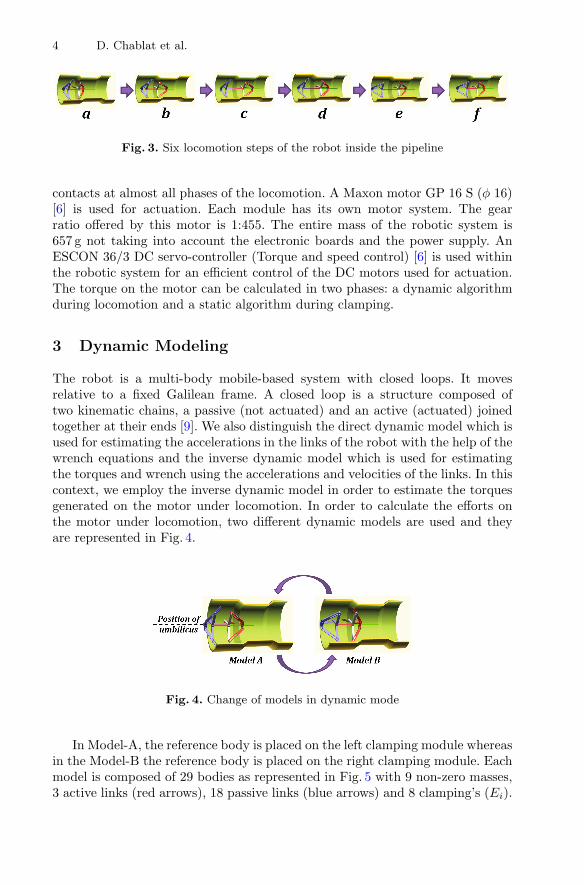
In Eqs. 1 and 2, Py signifies the position of the leg that establishes a contactwith the walls of the pipeline. In Eq. 3, Fa represents the actuation force of themotor and Fp signifies the contact forces between the legs of the robot and thewalls of the pipeline. The dimensions for the leg mechanism used in the robotare: l1 = 57 mm, l2 = 7 mm and ρ = 8.5–45.5 mm. The six locomotion steps ofthe robot inside the pipe are depicted in Fig. 3. The three legs of the rear andforward mechanisms have the same dimensions and they ensure non-hyper-static
4 D. Chablat et al.
Fig. 3. Six locomotion steps of the robot inside the pipeline
contacts at almost all phases of the locomotion. A Maxon motor GP 16 S (φ 16)[6] is used for actuation. Each module has its own motor system. The gearratio offered by this motor is 1:455. The entire mass of the robotic system is657 g not taking into account the electronic boards and the power supply. AnESCON 36/3 DC servo-controller (Torque and speed control) [6] is used withinthe robotic system for an efficient control of the DC motors used for actuation.The torque on the motor can be calculated in two phases: a dynamic algorithmduring locomotion and a static algorithm during clamping.
3 Dynamic Modeling
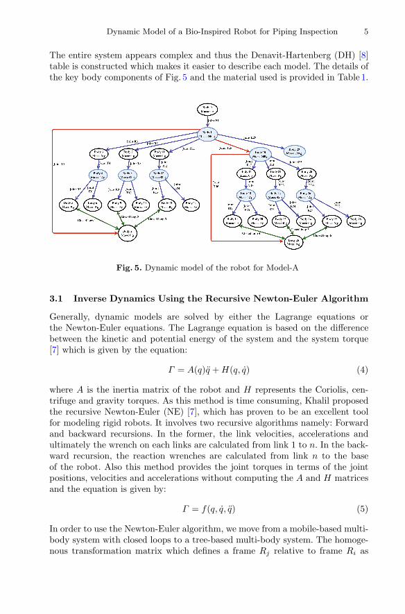
The robot is a multi-body mobile-based system with closed loops. It movesrelative to a fixed Galilean frame. A closed loop is a structure composed oftwo kinematic chains, a passive (not actuated) and an active (actuated) joinedtogether at their ends [9]. We also distinguish the direct dynamic model which isused for estimating the accelerations in the links of the robot with the help of thewrench equations and the inverse dynamic model which is used for estimatingthe torques and wrench using the accelerations and velocities of the links. In thiscontext, we employ the inverse dynamic model in order to estimate the torquesgenerated on the motor under locomotion. In order to calculate the efforts onthe motor under locomotion, two different dynamic models are used and theyare represented in Fig. 4.
Fig. 4. Change of models in dynamic mode
In Model-A, the reference body is placed on the left clamping module whereasin the Model-B the reference body is placed on the right clamping module. Eachmodel is composed of 29 bodies as represented in Fig. 5 with 9 non-zero masses,3 active links (red arrows), 18 passive links (blue arrows) and 8 clamping’s (Ei).
Dynamic Model of a Bio-Inspired Robot for Piping Inspection 5
The entire system appears complex and thus the Denavit-Hartenberg (DH) [8]table is constructed which makes it easier to describe each model. The details ofthe key body components of Fig. 5 and the material used is provided in Table 1.
Fig. 5. Dynamic model of the robot for Model-A
3.1 Inverse Dynamics Using the Recursive Newton-Euler Algorithm
Generally, dynamic models are solved by either the Lagrange equations orthe Newton-Euler equations. The Lagrange equation is based on the differencebetween the kinetic and potential energy of the system and the system torque[7] which is given by the equation:
Γ = A(q)q + H(q, q) (4)
where A is the inertia matrix of the robot and H represents the Coriolis, cen-trifuge and gravity torques. As this method is time consuming, Khalil proposedthe recursive Newton-Euler (NE) [7], which has proven to be an excellent toolfor modeling rigid robots. It involves two recursive algorithms namely: Forwardand backward recursions. In the former, the link velocities, accelerations andultimately the wrench on each links are calculated from link 1 to n. In the back-ward recursion, the reaction wrenches are calculated from link n to the baseof the robot. Also this method provides the joint torques in terms of the jointpositions, velocities and accelerations without computing the A and H matricesand the equation is given by:
Γ = f(q, q, q) (5)
In order to use the Newton-Euler algorithm, we move from a mobile-based multi-body system with closed loops to a tree-based multi-body system. The homoge-nous transformation matrix which defines a frame Rj relative to frame Ri as

6 D. Chablat et al.
Table 1. Description of key body parts represented in Fig. 5
Body No. Description Material
Body 1 Left leg actuator Steel
Body 4 Left leg-1 Bronze
Body 8 Left leg-2 Bronze
Body 12 Left leg-3 Bronze
Body 15 Central & right leg actuator Steel
Body 18 Right leg-1 Bronze
Body 22 Right leg-2 Bronze
Body 26 Right leg-3 Bronze
Body 29 Umbilicus(Cables) Copper
a function of six geometric parameters (γj , bj , αj , dj , θj , rj) is given by therelation:
iTj =
[iRj
iPj
01×3 1
](6)
where iRj defines the (3 × 3) rotation matrix and iPj defines the (3 × 1) vectorthat specifying the position of frame j with respect to frame i. The forward NErecursive equations [7] are given by:
jVj = j
TiiVi + jγj + qj
jAj (7)
where jAj is a (6 × 1) columns matrix called as the transposition vector for
velocities and accelerations and is given by:
jAj =
[0 0 σj 0 0 σj
]T (8)
Here σj is a coefficient of the joint type. If the joint is revolute σj = 0 and forprismatic joint σj = 1. Also σj = 1 − σj . j
Vj is a kinematic screw vector offrame j with a size of (6 × 1) and it contains the linear and angular velocitycomponents. The equation is given by:
jVj =
[Vj
T ωjT
]T(9)
where jTi is the screw transformation matrix and it is given by the equation:
jTi =
[jRi − jRi
iPj
03×3jRi
](10)
The wrench equation comprises of the external forces and torques and is pro-vided in (11). These forces and torques in the forward recursion is given by (12)and (13).
jFj =
[jFjjMj
](11)
Dynamic Model of a Bio-Inspired Robot for Piping Inspection 7
jFj = Mjj Vj + jUj
jMSj (12)jMj = jJj
jωj + jωj × (jJjjωj) + jMSj × j Vj (13)
Here MSj and Jj refers to the standard inertial parameters of the link j. Thebackward recursive equations are calculated with the help of the reaction forcesand torques generated on the joints j. The torque induced on the motor iscalculated with the help of the reaction forces based on (14) which is givenbelow [7]:
Γj = (σjjfj + σj
jmj)T j
aj + Iaj qj + Fsjsign(qj) + Fvj qj (14)
Here fj and mj are the reaction forces and torques from the links. Iaj is theinertia of the motor. Fsj and Fvj are the coulomb and viscous friction parame-ters. The forward and the backward recursive equations using NE algorithm areimplemented in MATLAB with the help of which the locomotion sequence ofthe robot and the forces on the actuators are estimated.
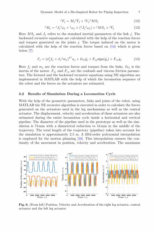
3.2 Results of Simulation During a Locomotion Cycle
With the help of the geometric parameters, links and joints of the robot, usingMATLAB the NE recursive algorithm is executed in order to calculate the forcesgenerated on the actuators used in the leg mechanisms as well as the centralactuator. The displacement, velocity and acceleration of these actuators are alsoestimated during the entire locomotion cycle inside a horizontal and verticalpipeline. The diameter of the pipeline used in the prototype as well as the sim-ulation is 74 mm with a diametrical reduction to 54 mm in the middle of thetrajectory. The total length of the trajectory (pipeline) taken into account forthe simulation is approximately 2.5 m. A fifth-order polynomial interpolationis employed for the motion planning [10]. This interpolation ensures the con-tinuity of the movement in position, velocity and acceleration. The maximum
0 1000 2000 3000 4000 5000
-80
-60
-40
-20
0
20
40
60
80
0 1000 2000 3000 4000 5000
-6
-4
-2
0
2
4
6
10-4
0 1000 2000 3000 4000 5000-3
-2
-1
0
1
2
310-5
Fig. 6. (From left) Position, Velocity and Acceleration of the right leg actuator, centralactuator and the left leg actuator
8 D. Chablat et al.
0 1000 2000 3000 4000 5000
-6
-4
-2
0
2
4
6
0 1000 2000 3000 4000 5000
-0.2
-0.15
-0.1
-0.05
0
0.05
0.1
0.15
0.2
0 1000 2000 3000 4000 5000
-6
-4
-2
0
2
4
6
Fig. 7. Forces induced on the actuators during locomotion with horizontal orientationof the pipeline for Model-B
0 1000 2000 3000 4000 5000
-6
-4
-2
0
2
4
6
0 1000 2000 3000 4000 5000
10.45
10.5
10.55
10.6
10.65
10.7
10.75
10.8
10.85
10.9
0 1000 2000 3000 4000 5000
-4
-2
0
2
4
6
Fig. 8. Forces induced on the actuators during locomotion with vertical orientation ofthe pipeline for Model-B
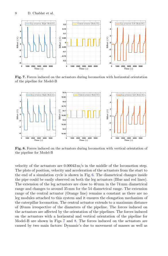
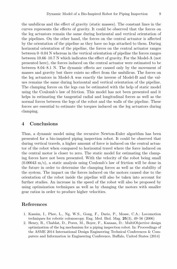
velocity of the actuators are 0.00043 m/s in the middle of the locomotion step.The plots of position, velocity and acceleration of the actuators from the start tothe end of a simulation cycle is shown in Fig. 6. The diametrical changes insidethe pipe could be easily observed on both the leg actuators (Blue and red lines).The extension of the leg actuators are close to 40 mm in the 74 mm diametricalrange and changes to around 35 mm for the 54 diametrical range. The extensionrange of the central actuator (Orange line) remains a constant as there are noleg modules attached to this system and it ensures the elongation mechanism ofthe caterpillar locomotion. The central actuator extends to a maximum distanceof 20 mm irrespective of the diameters of the pipeline. The forces induced onthe actuators are affected by the orientation of the pipelines. The forces inducedon the actuators with a horizontal and vertical orientation of the pipeline forModel-B are shown in Figs. 7 and 8. The forces induced on the actuators arecaused by two main factors: Dynamic’s due to movement of masses as well as
Dynamic Model of a Bio-Inspired Robot for Piping Inspection 9
the umbilicus and the effect of gravity (static masses). The constant lines in thecurves represents the effects of gravity. It could be observed that the forces onthe leg actuators remain the same during horizontal and vertical orientation ofthe pipelines. On the other hand, the forces on the central actuator is affectedby the orientation of the pipeline as they have no legs attached to them. Duringhorizontal orientation of the pipeline, the forces on the central actuator rangesbetween 0–0.04 N whereas in the vertical orientation of pipeline the forces rangesbetween 10.66–10.7 N which indicates the effect of gravity. For the Model-A (notpresented here), the forces induced on the central actuator were estimated to bebetween 8.04–8.1 N. The dynamic effects are caused only by the movement ofmasses and gravity but there exists no effect from the umbilicus. The forces onthe leg actuators in Model-A was exactly the inverse of Model-B and the val-ues remains the same during horizontal and vertical orientation of the pipeline.The clamping forces on the legs can be estimated with the help of static modelusing the Coulomb’s law of friction. This model has not been presented and ithelps in estimating the tangential radial and longitudinal forces as well as thenormal forces between the legs of the robot and the walls of the pipeline. Theseforces are essential to estimate the torques induced on the leg actuators duringclamping.
4 Conclusions
Thus, a dynamic model using the recursive Newton-Euler algorithm has beenpresented for a bio-inspired piping inspection robot. It could be observed thatduring vertical travels, a higher amount of force is induced on the central actua-tor of the robot when compared to horizontal travel where the force induced onthe central motor is closer to zero. The static model for estimating the clamp-ing forces have not been presented. With the velocity of the robot being small(0.00043 m/s), a static analysis using Coulomb’s law of friction will be done inthe future in order to determine the clamping forces as well as the stability ofthe system. The impact on the forces induced on the motors caused due to theorientation of the robot inside the pipeline will also be taken into account forfurther studies. An increase in the speed of the robot will also be proposed byusing optimization techniques as well as by changing the motors with smallergear ratios in order to produce higher velocities.
References
1. Kassim, I., Phee, L., Ng, W.S., Gong, F., Dario, P., Mosse, C.A.: Locomotiontechniques for robotic colonoscopy. Eng. Med. Biol. Mag. 25(3), 49–56 (2006)
2. Henry, R., Chablat, D., Porez, M., Boyer, F., Kanaan, D.: MultiObjective designoptimization of the leg mechanism for a piping inspection robot. In: Proceedings ofthe ASME 2014 International Design Engineering Technical Conferences & Com-puters and Information in Engineering Conference, Buffalo, United States (2014)
10 D. Chablat et al.
3. Anthierens, C., Ciftci, A., Betemps, M.: Design of an electro pneumatic micro robotfor in-pipe inspection. In: International Symposium on Industrial Electronics, Bled,pp. 968–972 (1999)
4. Anthierens, C., Libersa, C., Touaibia, M., Betemps, M., Arsicault, M., Chaillet,N.: Micro robots dedicated to small diameter canalization exploration. In: Inter-national Conference on Intelligent Robots and Systems, Takamatsu, pp. 480-485(2000)
5. Ur-Rehman, R., Caro, S., Chablat, D., Wenger, P.: Multiobjective path placementoptimization of parallel kinematics machines based on energy consumption, shakingforces and maximum actuators torques: application to the orthoglide. Mech. Mach.Theory 45(8), 1125–1141 (2010)
6. Maxon motor’s, Program 2017/18. High precision Drives and Systems. Information,pp. 363–427 (2017). http://epaper.maxonmotor.com/#1
7. Khalil, W.: Dynamic modeling of robots using recursive Newton-Euler techniques.In: 7th International Conference on Informatics in Control, Automation andRobotics, Portugal (2010)
8. Khalil, W., Kleinfinger, J.F.: A new geometric notation for open and closed-looprobots. In: Proceedings of IEEE International Conference on Robotics and Automa-tion, San Francisco, pp. 1174–1180 (1986)
9. Boyer, F., Ali, S.: Recursive inverse dynamics of mobile multibody systems withjoints and wheels. IEEE Trans. Robot. 27(2), 215–228 (2011)
10. Khalil, W., Dombre, E.: Modeling, Identification and Control of Robots. HermesPenton Ltd. (2002)