Embed Size (px)
Citation preview

i
All specifications are subject to change without notice. All sales subject to standard terms and conditions. © 2016 Ashcroft Inc. 10/16 I&M002-10106 Rev. C
DXD Series Precision Digital Pressure Transducer Operation and Maintenance Manual
SECTION 1.
Part 1. Installation And Operating Instructions.
Part 2. Command Library And Communication Specification.
SECTION 2.
DXD Setup Utility Manual

ii

1
TABLE OF CONTENTS SECTION TOPIC PAGESection 1.0 Introduction ........................................................................................................3Section 2.0 Cautions ..............................................................................................................3Section 3.0 Theory of Operation ...........................................................................................3Section 4.0 Unpacking ...........................................................................................................4Section 4.1 DXD Transducer(s) ..............................................................................................4Section 4.2 Certificate of Calibration .....................................................................................4Section 4.3 Utility Software ...................................................................................................4Section 4.4 Accessories (RS-232 Configurations only) .........................................................4 Figure 1. Modular Power Supply with RJ11/4 Connector ..................................4 Figure 2. Serial Port Adapter Assembly ..............................................................5Section 4.4.3 25 to 9 Pin Adapter ..........................................................................................5Section 4.4.4 25 Foot Cable ..................................................................................................5Section 4.4.5 Five-Port Expander Module .............................................................................5Section 4.4.6 Limitations of the DXD w/USB option .............................................................6Section 5.0 Installation ...........................................................................................................6Section 5.1 Pressure Connections .........................................................................................6Section 5.2 System Wiring ....................................................................................................6Section 5.2.1 RS-232 Cables .................................................................................................6Section 5.2.2 RS-485 Cables .................................................................................................6Section 5.2.3 USB Cables .....................................................................................................6Section 5.2.4 Cable Length and Transmission Speed (RS-232 & RS-485) ...........................7Section 5.2.5 Pin Functions and Cable Fabrication for RS-232 Compatible Systems ..........7Section 5.3 Installation Wiring for RS-232 Systems with Accessory Kit ...............................7Section 5.3.1. Pin Functions and Cable Fabrication for RS-232 Compatible Systems .........7 Table 1. Switchcraft™ EN3 Pin Assignments for RS-232 Configuration ............8 Table 2. ITT Cannon™ KPT03 Pin Assignments for RS-232 Configuration .......8 Table 3. RJ-11 Connector Functions for RS-232 Systems .................................8Section 5.4 Wiring Installation for RS-485 Systems ........................................................ 9-11Section 5.4.1 Pin Functions and Cable Fabrication for RS-485 Compatible Systems ........12 Table 4. Switchcraft™ EN3 Pin Assignments for RS-485 Configuration ..........10 Table 5. ITT Cannon™ KPT03 Pin Assignments for RS-485 Operation ...........11 Figure 3. USB cable assembly ..........................................................................12Section 5.5 Wiring System for USB applications.................................................................12Section 6.0 Installing and Running Utility Software .............................................................14Section 7.0 Using HyperTerminal™ (or other Terminal Emulators) with the DXD ................14Section 7.1 Configuring HyperTerminal™ ...................................................................... 14-15Section 7.2 Basic Communications with the DXD ..............................................................15Section 7.2.1 Communication and Command Basics .........................................................15Section 7.3 Launching the Previously Configured HyperTerminal Application ....................15Section 7.4 Talking to the DXD with HyperTermnal™ ..........................................................15Section 7.4.1 Determine and Set the Current Address .................................................. 15-16Section 7.4.2 Determine and Set Baud Rate .......................................................................16Section 7.4.3 Determine the Pressure Type .........................................................................17Section 7.4.4 Determine the Full Scale Pressure Range .....................................................17Section 7.4.5 Get a Pressure Reading .................................................................................17Section 7.4.6 Get the Heise Label .......................................................................................17Section 7.4.7 Get and Change the Current User Label .......................................................17Section 7.4.8 Get and Change the Current User Tare Value ................................................17Section 8.0 Field Calibration ................................................................................................18Section 8.1 Zero Adjustment ...............................................................................................18Section 8.2 Span Adjustment ..............................................................................................18Section 9.0 Command Library Command Specification ............................................... 18-19Section 9.1 Communication Settings ..................................................................................19Section 9.2 Communication Protocol ..................................................................................19Section 9.2.1 Read Commands ...........................................................................................19Section 9.2.2 Write Commands ...........................................................................................19Section 9.3 Command Library Mnemonics .........................................................................19Section 10.0 DXD Product Specifications ..................................................................... 20-21

2
COMMAND LIBRARY COMMUNICATION SPECIFICATION
DXD Firmware Change Summary:....................................................................................... 23-24Communications Introduction ...................................................................................................25Comunications Settings ............................................................................................................25Communications Protocol .........................................................................................................25Eeprom Lock ............................................................................................................................26Command Library Mnemonics .................................................................................................26 AD Unit Address ................................................................................................................26 BR Baud Rate ...................................................................................................................27 ED Eeprom Memory Map Dump ........................................................................................27 EF Error Flag .....................................................................................................................28 ER Read From Eeprom Address. .......................................................................................28 EW Write To Eeprom Address.............................................................................................28 EZ Eeprom Zero (Initialize Eeprom) ...................................................................................29 FA Filter Amount ................................................................................................................29 FB Filter Band ....................................................................................................................30 FS Full Scale Value ............................................................................................................30 FV Firmware Version ..........................................................................................................31 HI Heise Label (Serial Number) .........................................................................................31 PS Psi Reading ..................................................................................................................31 PT Pressure Type ...............................................................................................................31 RC Raw Counts .................................................................................................................32 ST Sensor Temperature .....................................................................................................32 UL User Label ....................................................................................................................32 US User Span ....................................................................................................................33 UT User Tare ......................................................................................................................33 UZ User Zero .....................................................................................................................34 BA Bar Reading .................................................................................................................34 CW Cm Of Water Reading ..................................................................................................34 FW Feet Sea Water Reading ..............................................................................................35 HP Hectopascal Reading ...................................................................................................35 IM Inches Of Mercury Reading..........................................................................................35 IW Inches Of Water Reading .............................................................................................35 KP Kilopascal Reading ......................................................................................................36 MB Millibar Reading ...........................................................................................................36 MM Mm Of Mercury Reading ..............................................................................................36 MP Megapascal Reading ...................................................................................................36 NP Numeric Value ..............................................................................................................36Transducer Command Summary ..............................................................................................37Read Command Summary ........................................................................................................37AEU Command Summary .........................................................................................................38Write Command Summary ........................................................................................................37Error Codes (Legacy Mode) ......................................................................................................37AEU Scale Factors ....................................................................................................................38Mode Byte .................................................................................................................................38Detailed Explanation of the “FA” & “FB” Commands................................................................40Alternate Engineering Units (AEU) Explained ............................................................................42Update Rate Modifications ........................................................................................................42Synchronous Read Command (Addendum A) .........................................................................44Read Commands Summary ......................................................................................................45ATS Varient (Addendum B) ........................................................................................................46DXD Receiver to Transmit Delay Capabilities (allows half duplex operation in RS-485) ..........48ASCII Character Code Table (page 26 of Installation and Operation Instructions)DXD Set-up Utility, Manual/Software .................................................................................. 51-71
TABLE OF CONTENTS (cont.)

3
Congratulations on your purchase of a DXD Series Digital Pres-sure Transducer. This transducer provides unmatched perfor-mance and value. Innovative modeling and processing firmware assures extremely high precision over a broad temperature range as well as extremely fast response. Please read the following cautions and instructions carefully in order to take full advantage of the product’s capabilities.
Pressure instruments must be selected in accordance with indus-try codes and safety practices to avoid the possibility of misuse or misapplication, which could result in personal injury or property damage. Personnel responsibility for selection and installation should also be familiar with the safety recommendations of ANSI/ASME B40.100-2013, that apply to elastic pressure elements and their application general and specific services. ANSI/ASME B40.100-2013 is available from: ASME Two Park Avenue New York NY 10016-5990
Email: [email protected]
• Select a range so that the maximum applied pressure will never exceed the upper range limit.
• Excessive vibration could cause loosening of components resulting in loss of instrument accuracy or failure to provide valid data.
• Excessive pressure pulsation could result in fatigue failure of the pressure element.
• Operation of the instrument in an environment where tempera-tures are in excess of design ratings may result in loss of accu-racy or failure.
• Pressure boundary materials must be resistant to the process media. Failure to ensure compatibility may result in pressure sensing element deterioration or failure. Instruments used on high pressure gas, or potentially hazardous service, such as oxygen should be carefully selected in accordance with the recommendations of ANSI/ASME 40.100-2013.
• Only approved explosion proof or intrinsically safe instruments should be used in hazardous locations.
• Instruments used in locations where EMI/RFI conditions exist may exhibit erroneous performance.
• These instruments are not explosion proof or intrinsically safe. Power levels present preclude use in hazardous locations.
The DXD transducer design employs a piezo resistive strain gauge, a 24 bit A/D converter, microprocessor, and a 20 MHz clock. The A/D resolution is internally reduced to 50,000 counts in order to optimize signal to noise ratio. The raw data is pro-cessed with a proprietary algorithm which employs a 4th order polynomial. The math package fits both temperature and pressure signals from the transducer using coefficients calculated from the outputs of pressure and temperature standards during the calibra-tion process. The internal update rate can be can be set to 27.7 mS or 12.6 mS. The DXD responds to a simple ASCII command protocol. The total transmit/receive time is for fully corrected pres-sure data is 30 mS (when set to 27.7 mS) and 15 mS (when set to 12.6 mS) at 115200 bps. There may be a slight reduction in signal stability (1 to 3 counts) when operated at 15 mS, as the difference in signal processing time is gained at the expense of filtering in the processor. The firmware supports addressable, multi-drop operation (except when equipped with the USB option and using ASHCROFT provided utility software). Electrical communications are via full duplex RS-232, RS-485 or USB standards. The maxi-mum resolution is 50,000 counts.
SECTION 1.0 INTRODUCTION
SECTION 2.0 CAUTIONS
SECTION 3.0 THEORY OF OPERATION

4
Please note: When handling connectors care should be used to avoid electrostatic discharge to prevent damage to the electronics. The power pins are reverse polarity protected. Use caution if fabricating connector and cable assemblies because the digital I/O lines are not protected from the inad-vertent application of power.
Following is a description of material included in shipment.
The DXD is available in a variety of standard pressure ranges and types as specified at time of order. It is configured for either RS-232, RS-485 or USB operation at the factory as specified at time of purchase. The output is not field configu-rable. Please check the product label to ensure that the pres-sure range and output signal type are correct.
Each DXD is provided with a report of calibration traceable to NIST. The report is packaged with the transducer.
Software is provided on a Flash Drive (Memory Stick). The Windows™ compatible (WinXP™, Win7™ or Win10™) soft-ware simplifies the setup and installation of the DXD. It also provides powerful data logging and pressure display capa-bilities. Win7™ and WinXP™ compatible LabVIEW™ drivers along with the LabVIEW™ Runtime Engine are also available.
The following accessory items are available individually or in kit form at time of order. These accessories are designed for use with the RS-232 version of the product. The DXD with complete kit options includes the following items:
The AC Adapter supplies 12 VDC power @500 mA (Fig.1) connects to the Serial Port Converter and the DXD Trans-ducer (s) which are interconnected, forming a “network”. The DXD has its own regulated power supply (internal DC to DC Converter) and is protected against spikes and power supply reversal. Each DXD consumes approximately 300 milliwatts, or 15 ma at 20 volts. The power supply can be plugged in anywhere along the network, it does not need to be near the Serial Port Converter. The contact rating of the RJ11/4 (telephone type) connector is 1.5 amps which provides a fast economical method of interconnection.
Figure 1. Modular Power Supply with RJ11/4 Connector (831X015-01 Shown)
SECTION 4.0 UNPACKING
SECTION 4.2 CERTIFICATE OF CALIBRATION
SECTION 4.1 DXD TRANSDUCERS
SECTION 4.3 UTILITY SOFTWARE
SECTION 4.4 ACCESSORIES
SECTION 4.41 MODULAR POWER SUPPLY
5
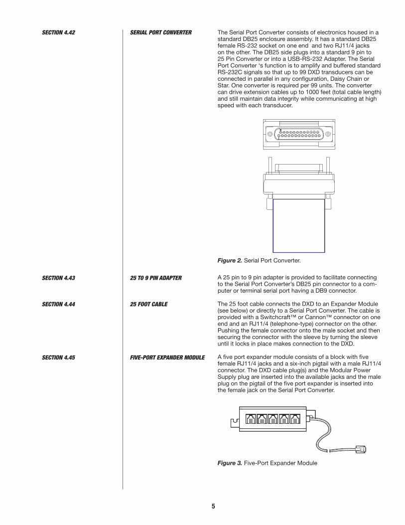
The Serial Port Converter consists of electronics housed in a standard DB25 enclosure assembly. It has a standard DB25 female RS-232 socket on one end and two RJ11/4 jacks on the other. The DB25 side plugs into a standard 9 pin to 25 Pin Converter or into a USB-RS-232 Adapter. The Serial Port Converter ‘s function is to amplify and buffered standard RS-232C signals so that up to 99 DXD transducers can be connected in parallel in any configuration, Daisy Chain or Star. One converter is required per 99 units. The converter can drive extension cables up to 1000 feet (total cable length) and still maintain data integrity while communicating at high speed with each transducer.
Figure 2. Serial Port Converter.
A 25 pin to 9 pin adapter is provided to facilitate connecting to the Serial Port Converter’s DB25 pin connector to a com-puter or terminal serial port having a DB9 connector.
The 25 foot cable connects the DXD to an Expander Module (see below) or directly to a Serial Port Converter. The cable is provided with a Switchcraft™ or Cannon™ connector on one end and an RJ11/4 (telephone-type) connector on the other. Pushing the female connector onto the male socket and then securing the connector with the sleeve by turning the sleeve until it locks in place makes connection to the DXD.
A five port expander module consists of a block with five female RJ11/4 jacks and a six-inch pigtail with a male RJ11/4 connector. The DXD cable plug(s) and the Modular Power Supply plug are inserted into the available jacks and the male plug on the pigtail of the five port expander is inserted into the female jack on the Serial Port Converter.
Figure 3. Five-Port Expander Module
SECTION 4.43 25 T0 9 PIN ADAPTER
SECTION 4.42 SERIAL PORT CONVERTER
SECTION 4.44 25 FOOT CABLE
SECTION 4.45 FIVE-PORT EXPANDER MODULE
H
I

6
Note that for DXD units with the USB interface, only the provided USB cable is required for operation, as all power is provided through the cable. Each DXD will require its own USB port on the PC or a powered HUB (not available through ASHCROFT Inc.)
Due to the limitations of the existing utility provided by Ashcroft, only one DXD can be addressed at any one time. If more than one DXD w/USB needs to be communicated with, an alternate utility program will be required, which should be provided by the user.
The installation of the product has three basic steps, which includes making a pressure connection, system wiring (connecting communication and power cables to the trans-ducers and a PC or PLC) and installing and running software to communicate with and set up the DXD transducer.
The standard pressure inlet fitting is a ¼ inch NPTM type connector for pressures less than 5000 psi (or equivalent) and 9/16 – 18 UNF 2B Female port for ranges greater than 5000 psi. Optional fittings are available – consult factory for specific information.
Important Note: The standard vented housing is recom-mended for gauge pressure types with ranges less than 500 psi. This is because changes in ambient temperature will increase or decrease the pressure of the gas volume within the housing, producing an undesirable effect on the performance of the unit. The housing is vented through the Switchcraft™ or Cannon™ electrical connector by removing one of the unused connector pins at the factory. For USB option devices the enclosure is vented with a porous mem-brane (see Table 1 and 2). A sealed housing (no connector pin removed) can be specified at time of purchase if required. The effect is approximately ±.027 PSI per degree Fahrenheit change in ambient temperature.
This is not a factor with absolute pressure ranges because the reference side of the sensor is evacuated and sealed.
The RS-232 configuration requires four conductors for Signal In, Signal Out, Power Positive and Power Negative. Prefabri-cated telephone type cables with RJ11 modular connectors and Switchcraft™ or ITT Cannon™ connectors can be pur-chased from the factory as a kit for RS-232 configurations. Other cable and connector combinations can be fabricated using user supplied, multiconductor wire and connectors per the following pin function tables. Minimum 26 AWG wire is recommended.
The RS-485 configuration requires six conductors, two for Signal In, two for Signal Out, one for Power Positive, and one for Power Negative. The user can fabricate similar telephone type cable and modular connectors for RS-485 configura-tions. This configuration uses eight conductor RJ45 plugs, sockets and cables, such as Alpha #9314C 24 AWG. Other cable and connector combinations can be fabricated using user supplied, multi-conductor wire and connectors. Mini-mum 26 AWG wire is recommended.
USB configuration requires cabling with a 2.0 Type A Jack (host system) at one end and a 2.0 Type mini B Jack (DXD transducer) at the other. The DXD transducer will obtain power through the cable from the host system. Ensure that adequate power is available in cases where multiple DXD transducers are arranged in a network. If the end user is
SECTION 4.46 LIMITATIONS OF THE DXD W/USB OPTION
SECTION 5.2 SYSTEM WIRING
SECTION 5.0 INSTALLATION
SECTION 5.1 PRESSURE CONNECTION
SECTION 5.2.1 RS-232 CABLES
SECTION 5.2.2 RS-485 CABLES
SECTION 5.2.3 USB CABLES

7
using a software utility capable of addressing more than one DXD w/USB at a time (note limitations of the Ashcroft Sup-plied Utility in section 4.6). Use powered hubs if the host sys-tem’s power requirements are not adequate for total number of DXD transducers on the network.
Total cable length, wire gauge and total number of transduc-ers connected to the system have an effect on maximum communication speed. This is due to the effects of cumula-tive resistance and capacitance on the signals. The tables in appendix B illustrate the relationship between cable length, number of DXD transducers and communication speed. For USB configurations, standard USB specifications apply.
The DXD is available with a standard Switchcraft™ EN3 elec-trical connector or an optional ITT Cannon™ KPT03 (Bendix PTX compatible) electrical connector, or a Mini B USB female connector.
Typical RS-232 System Configuration
The following information is provided for reference if you wish to fabricate your own cables. The Switchcraft™ EN3 connec-tor has eight pins. The RS-232 configuration utilizes four pins with the following assignments and functions:
SECTION 5.2.4 CABLE LENGTH & TRANSMIS-SION SPEED (RS232 & RS-485)
SECTION 5.2.5 TRANSDUCER CONNECTIONS
SECTION 5.3 INSTALLATION WIRING FOR RS-232 SYSTEMS WITH ACCESSORY KIT
SECTION 5.3.1 PIN FUNCTIONS & CABLE FABRICATION FOR RS-232 COMPATIBLE SYSTEMS
Ashcroft P/N 831X015-03, POWER SUPPLY
Ashcroft Pt. # 838X002-01,
25 TO 9 Pin ADAPTER
Ashcroft Pt. # 838X003-01,
SERIAL PORT ADAPTER
Ashcroft Pt. # 838X001-01,
5 PORT EXPANDER
HOST PC
RS
-232

8
1
2
3
4
5
6
7
8
N/A
SUPPLY (+)
N/A
DIGITAL OUTPUT
N/A
DIGITAL INPUT
SUPPLY COMMON
N/A
*PIN FUNCTION FORRS-232 APPLICATION
“SWITCHCRAFT”CONNECTOR PIN
I.D.
*IMPORTANTREQUIRES USE OF
SERIAL PORTCONVERTER (#838X003)
FOR RS-232FUNCTIONALITY
POSITION #1
POSITION #4
POSITION #7
POSITION #2
POSITION #3 POSITION #5
POSITION #6
POSITION #8
PIN ID INDEX RIB LOCATEDAT BOTTOM OF RECESS.INDEX RIB IS ALIGNED WITH INDEX GROOVEON OPPOSITE END OF CONNECTOR.
NO PIN IN THIS POSITION FOR VENTED CONNECTOR
A
B
C
D
E
F
G
H
N/A
SUPPLY (+)
N/A
DIGITAL OUTPUT
N/A
DIGITAL INPUT
SUPPLY COMMON
N/A
*PIN FUNCTION FORRS-232 APPLICATION
“ITT CANNON”CONNECTOR PIN
I.D.
*IMPORTANTREQUIRES USE OF
SERIAL PORTCONVERTER (#838X003)
FOR RS-232FUNCTIONALITY
E C
G
HFB
D
A
Table 1. Switchcraft EN3 Pin Assignment for RS-232 Configuration Solder Cup View
Table 2. ITT Cannon KPT03 Pin Assignment for RS-232 Configuration

9
Table 3. RJ11 Connector Functions for RS-232 Systems
RS-232 Customer Connector
A typical RS-485 System Interconnection Diagram is shown on page 12. This configuration uses some components that are supplied by Ashcroft.
Power Supply. A DC Power Supply capable of providing 12 to 24 VDC and 15 mA per Transducer is required.
–
–
––
––
––
8
7
6
5
4
3
2
1
–
–
–
–
“SWITCHCRAFT”CONNECTOR PIN
I.D.
“ITT CANNON”CONNECTOR PIN
I.D.
DIGITAL OUTPUT
DIGITAL INPUT
RJ11 PLUG
HOST DESTINATIONFUNCTIONS FORRS-232
APPLICATION
DXD DEFINITION
WIRE COLOR
BLACK
RED
GREEN
YELLOW
SECTION 5.4 WIRING INSTALLATION FOR RS-485 SYSTEMS
YELLOW WIRE GREEN WIRE
RED WIRE
BLACK WIRE

10
Required Equipment (RS-485)
Either an RS-485 Card, such as B&B Electronics “MIPORT” Isolated PCI Multi-Output Card (model #3PCIOU1), or an RS-485 Adapter (B&B Model USPTL-4) capable of running in full duplex mode is required for setting up an RS-485 system.
Connectors: The DXD is supplied with either Switchcraft or Cannon connectors as specified at time of purchase. The pin identification and assignments are shown in Tables 4 and 5.
Table 4. Switchcraft EN3 Pin Assignments for RS-485 Configuration
PIN 1
PIN 2
PIN 3
PIN 4
PIN 5
PIN 6
PIN 7
PIN 3
PIN 8
PIN 1 INDEX
1
2
3
4
5
6
7
8
+5V (OUT)
SUPPLY (+)
TXD+
TXD–
RXD+
RXD–
SUPPLY COMMON
N/A
*PIN FUNCTION FORRS-485 APPLICATION
“SWITCHCRAFT”CONNECTOR PIN
I.D.
SECTION 5.4 WIRING INSTALLATION FOR RS-485 SYSTEMS (CONT.)

11
Wiring: According to the RS-485 standard, six conductor, shielded, twisted pair 24 AWG wire is recommended for inter-connecting RS-485 systems. However, modular telephone cable (CAT5 or CAT6 rated) and hardware (RJ45 six conduc-tor) can be employed depending on the application (distance, EMI, RFI, speed). Daisy chain interconnection is recommended with minimum drop lengths. See RS-485 schematic, appendix C.
Table 5. ITT Cannon – (Bendix) Compatible Pin Assignments for RS-485 Operation
A
B
C
D
E
F
G
H
+5V (OUT)
SUPPLY (+)
TXD+
TXD–
RXD+
RXD–
SUPPLY COMMON
N/A
*PIN FUNCTION FORRS-485 APPLICATION
“ITT CANNON”CONNECTOR PIN
I.D.
E C
G
HFB
D
A

12
Use either the screw type captive USB cable provided (Ashcroft part no. 611C254-02) (USB Firewire Model RR-214320-05-78) shown below, or a standard USB cable with a Mini B type connector at the device end. It is recom-mended to use the screw type captive connector provided with the system.
USB Firewire Model RR-214320-05-78
SECTION 5.5 USB APPLICATIONS
SECTION 5.4.1 PIN FUNCTIONS & CABLE FABRICATION FOR RS-485 COMPATIBLE SYSTEMS
Various cable components are available from the factory for assembling an RS-485 network. Shown below are ‘Y’Splitters for either plastic Switchcraft (838D023-01) or metallic (ITT Cannon (838D024-01) connectors. (Cannon) type connectors.
838D024-01
Ashcroft P/N 831X015-03, POWER SUPPLY
Ashcroft Pt. # 828X023-01, DXD RS-485 ADAPTER CABLE
Ashcroft Pt. # 838X022-01,
MODULAR ADAPTER
B & B Electronics
Model USPTL4 Adapter

13
1 2 3 4 5 6 7 8
1 2 3 4 5 6 7 8
WHI
TE/O
RANG
E
ORAN
GE
WHI
TE/G
REEN
BLUE
WHI
TE/B
LUE
GREE
N
WHI
TE/B
ROW
N
BROW
N
1 2 3 4 5 6 7 8
1 2 3 4 5 6 7 8
WHI
TE/O
RANG
E
ORAN
GE
WHI
TE/G
REEN
BLUE
WHI
TE/B
LUE
GREE
N
WHI
TE/B
ROW
N
BROW
N
BROWN
WHITE/GREEN
BLUE
WHITE/BLUE
ORANGE
WHITE ORANGE
SUPPLY COMMON
SUPPLY +
RXD +
RXD –
TXD +
TXD –
G
B
E
F
C
D
BROWN
WHITE/GREEN
BLUE
WHITE/BLUE
ORANGE
WHITE ORANGE
SUPPLY COMMON
SUPPLY +
RXD +
RXD –
TXD +
TXD –
7
2
5
6
3
4
9 PIN FEMALE“D”-TYPE
CONNECTOR
“BENDIX”STYLE
CONNECTOR(ITT CANNON)
RJ45JACK
SWITCHCRAFTCONNECTOR
MODULAR ADAPTERD89 FEMALE TO RJ45 JACK
RJ45 TO RJ45 CABLETWISTED PARS 1-2, 3-6, 4-5, 7-8
RJ45 MODULAR “Y”CONNECTOR
(“BENDIX” STYLE)
RJ45 TO RJ45 CABLETWISTED PARS 1-2, 3-6, 4-5, 7-8
RJ45 MODULAR “Y”CONNECTOR
(SWITCHCRAFT)
TXD
– (T
O RX
D –)
RXD
+ (T
O TX
D +
)
RXD
– (T
O TX
D –)
TXD
+ (T
O RX
D +
)
GND
3 4 5 6 8
RS-485 SCHEMATIC DIAGRAM
POWERSUPPLY
–
+
7 8
SECTION 5.5 USB APPLICATIONS (CONT.)

14
Computer Requirements: Any PC capable of running Win-dows XP, or Win7 or Win10™ can be used.
Software: A data stick (flash drive) is available for the DXD transducer that provides an easy means of setting up the user configurable features of the DXD along with data logging and display capabilities, also avilable for download on our web site.
DXD w/ USB Users: After connecting the DXD into the USB connector of your PC it will be necessary to determine which communications port Windows has assigned to the DXD. This communications port assignment must be matched to the communications port used within the DXD utility.
To find the assigned port: Go to your PC’s “Control Panel” through the “Start” menu of your PC. Select “Device Man-ager” (it may be under “System” / “Hardware” on some oper-ating systems). Pull down the “Comm Port” headings and look for the communications port assignment for the DXD. To verify which comm port was assigned, if not evident, you can remove the DXD from the system and see which port disappears after the device manager automatically updates. Re-connect the DXD and see which port is re-established. Match that port to the comm port in the DXD utility.
For use with Windows 7, 10 a 3rd party terminal emulation program can be used (HyperTerminal™, Tera Term, PuTTY etc.). Windows XP includes a utility terminal emulation pro-gram called HyperTerminal™. A terminal emulator can be used to set up user preferences such as (DXD) address, label etc. and also to read pressure. The following section will guide you through the steps required to accomplish this. This tutorial in DXD command structure utilizes HyperTerminal™ as the reference, but should be adaptable to any other termi-nal emulator, provided you are familiar with the setup charac-teristics of those programs. The command syntax illustrated in the following section will familiarize you with how they are implemented if you wish to write your own program.
Basic Setup InformationEach DXD transducer is configured for address value = 01 and bit rate = 19,200 bits per second as shipped from the factory. These values can be changed, however, the following instructions assume that you are using the DXD in the factory configuration.
Signal and Power ConnectionsMake all electrical and power connections as described in Section 5.0. IMPORTANT: Be sure to connect only one DXD until you are familiar with addressing conventions.
The HyperTerminal™ application prompts you through the process of setting up communication parameters that include assigning a file name and icon and also setting the com port, data format, bps (bit per second). After this is done, you can save the configuration using a name like “DXD” and simply open it by name without the need to re-configure it each time it is used. This application will work with RS-232 ports, RS-485 ports or USB to RS-232 (RS-485) adapters.1. Click the Start Button on the task bar and drag up to Run…2. Type “hypertrm” in the text box and click OK.3. You will be prompted for a name, so use something easy
to remember, like DXD. Type the name and select an icon. Click the OK Button.
4. In the next box you may be prompted for a phone number. Pull down the Connect Using box and choose the appro-priate Com Port and click OK. (note – a phone number isn’t used in this type of setup).
SECTION 6.0 INSTALLING AND RUNNING UTILITY SOFTWARE
SECTION 7.0 USING A TERMINAL EMULATION PROGRAM
SECTION 7.1 CONFIGURING HyperTerminal™

15
5. Next you will be prompted for Com Port setup which should be configured as follows:
Bits Per Second 19200 Data Bits 7 Parity Even Stop Bits 1 Flow Contro None6. Next click on the Settings tab and click the ASCII Setup
button.7. Click in the Check Boxes labeled
m Send line ends with line feeds m Echo typed characters locally Click OK to close this box, and OK to close the next box.
8. You have now configured HyperTerminal to communicate with the DXD. Open the File drop box in the upper left hand corner of the window and select Save. This will save the Com Port configuration for later use.
9. Open the File drop box in the upper left hand corner of the HyperTerminal window and select Exit. You will be prompted by an alert message stating that you are cur-rently connected and asking if you want to terminate now. Click Yes, and HyperTerminal will close.
The command library in Section 9 contains a detailed description of all of the DXD commands, responses and data formats. It also outlines the command syntax required to read from or write to the DXD. The following section describes how to use these commands via HyperTerminal.
There are some basic conventions and characteristics which must be observed in order to communicate with the DXD.
• The data format is 7 data bits, 1 stop bit , even parity.• All commands are prefaced with the pound sign charac-
ter (“#”, ASCII 35) which serves as an attention character.• All responses are alphanumeric and include a carriage
return (CR) and line feed (ASCII 13 and 10 respectively).• The pound sign is always followed by a two character
numeric address (01 through 99). Note that with one DXD connected you can substitute a double asterisks (“*”, ASCII 42) if you don’t know the current address value.
• The DXD has two categories of commands, which are Read (get data from) and Write (send data to) the DXD. All Read commands are issued as upper case characters and corresponding Write commands are issued using lower case characters followed by the data to be written.
• The format of data used in write commands is critical, so please review the command library if you encounter prob-lems in the following section.
Note: The [CR] in the following example means hit the Enter key. A carriage return (ASCII 13) is required to terminate a read or write command.
1. Ensure that only one DXD is connected to the computer and that power is applied.
2. Click the Start button on the task bar, select All Pro-grams, then Accessories and then click on Hyper-Terminal. This will open a folder on the desk top that contains the HyperTerminal setup that you created in the preceding section. Double click on the File icon to launch HyperTerminal. When the program opens, it will be properly configured to communicate with the DXD set to factory defaults.
The value retrieved with the AD (Address) command is com-prised of 7 alphanumeric characters (including CR/LF) that can be modified by the user to set a desired address value.
SECTION 7.2.1 COMMUNICATIONS & COMMAND BASICS
SECTION 7.3 LAUNCHING THE PREVIOUSLY CONFIGURED HyperTerminal APPLICATION
SECTION 7.4 TALKING TO THE PREVIOUSLY CONFIGURED DXD WITH HyperTerminal
SECTION 7.4.1 DETERMINE AND SET THE CURRENT ADDRESS
SECTION 7.2 BASIC COMMUNICATIONS WITH THE DXD
SECTION 7.1 CONFIGURING HyperTerminal™ (CONT.)

The address of the DXD is user configurable and the factory default value is 01.
Note: There may be circumstances where the address of a DXD is unknown. To simplify the task of determining the current address setting, the DXD can recognize a “wild card” value comprised of double asterisks (**). Substitute it in the address portion of a read command. For example, a #01AD can be sent as #**AD (provided only one DXD is connected to the system). 1. To determine the DXD’s current address, type the follow-
ing command: #**AD[CR] 2. The DXD will respond with the following message
AD=01, indicating that the DXD’s address is currently configured to the value of 01.
3. To change the DXD’s address from 01 to 02, type the following command: #01ad02[CR]
4. To verify that the address has been changed, send the following message: #AD02[CR]
5. The DXD will respond with the following message: AD=02
6. To change the DXD’s address back to 01, type the fol-lowing command: #01ad[CR]
7. To verify that the address has been changed, type the following command: #01AD[CR]
8. The DXD will respond with the following message: AD=01
The value retrieved with the BR (Baud Rate) command is comprised of 11 alphanumeric characters (including CR/LF) which can be modified by the user to set the desired system baud rate. 1. To read the current baud rate, type the following com-
mand in the HyperTerminal window: #01BR[CR] 2. The DXD will respond with the following message:
BR=19200 3. To change the current baud rate, you must first change
the DXD’s settings, then change the com port settings for HyperTerminal to match. To change the DXD baud rate from 19200 to 9600, type the following command: #01br=9600[CR]
4. You will be unable to communicate with the DXD until the com port settings have been changed in HyperTerminal.
5. To do this, click “File” from the menu bar and select “Properties” from the pull-down selections. When the Properties Dialog opens, click on the “Configure” button. (Note: if the “Configure” button is grayed out then select “Call” from the menu bar, then click “Disconnect”). From the Com Properties Dialog Box, click the pull-down next to “Bits per Second”, then select 9600. Click OK to close the Com Properties Dialog Box. Finally, click OK to close the Properties Dialog Box.
6. To read the revised baud rate, type the following com-mand: #01BR[CR]
7. The DXD will respond with the following message: BR=9600
8. To change the baud rate back to 19200 type the following command: #01br=19200[CR]
9. Remember that you will be unable to communicate with the DXD until the com port settings are changed in HyperTerminal.
10. To do this click on the “File” menu and select “Properties” from the pull-down menu selection. Click the “Config-ure” button on the Properties Dialog, then select 19200
SECTION 7.4.2 DETERMINE AND SET THE CURRENT BAUD RATE
16
SECTION 7.4.1 DETERMINE AND SET THE CURRENT ADDRESS (CONT.)

from the “Bits per Second” pull-down. Click OK to close. Finally click OK to close the Properties Dialog.
11. To read the revised baud rate, type the following com-mand: #01BR[CR]
12. The DXD will respond with the following message: BR=19200
1. The value retrieved with the PT (Pressure Type) com-mand is the pressure type of the unit. It is comprised of 6 alphanumeric characters (including CR/LF) and specifies the pressure type of the transducer. It is assigned during manufacturing and cannot be changed. To read the pres-sure type (gauge, absolute, vacuum, compound) type the following command: #01PT[CR]
2. The DXD will respond by transmitting the following mes-sage to the HyperTerminal window: PT=G (G for Gauge, A for Absolute, V for Vacuum, C for Compound).
1. The value retrieved with the FS (Full Scale) command is the full scale pressure range of the unit. It is comprised of 13 alphanumeric characters (including CR/LF) and spec-ifies the pressure range of the transducer. It is assigned during manufacture and cannot be changed. To read the current FS value, type the following command in the HyperTerminal window. #01FS[CR]
2. The DXD will respond by transmitting the following message to the HyperTerminal window: FS=+30.000 (Note that the decimal position is range dependent. See Appendix A for details.)
1. To read the current pressure in PSI, type the following command in the HyperTerminal window: #01PS[CR]
2. The DXD will respond by transmitting the following mes-sage to the HyperTerminal window: PS=+000.000 (or the value of the current pressure)
1. The value retrieved with the HL (Heise Label) command is the serial number assigned to the unit during manufacture and cannot be changed. To read the value stored in the HL location, type the following command: #01HL[CR]
2. The DXD will respond by transmitting the following mes-sage: HL=000XXX (where X represents your DXD actual serial number)
1. The value retrieved with the UL (User Label) command is comprised of up to 16 alphanumeric characters which can be modified by the user to form a descriptive tag or identification name. To read the current User Name, type the following command: #01UL[CR]
2. The DXD will respond by transmitting the following mes-sage: UL=User Label Here (this is factory default value).
3. To change the current user label to “Test Point 01”, type the following command: #01ulTest Point 01[CR]
1. The value retrieved with the UT (User Tare) command is comprised of 11 alphanumeric characters which can be modified by the user to remove, or “tare out” a pressure preload from the displayed pressure value. To read the current user tare value, type the following command: #01UT[CR].
2. The DXD will respond by transmitting the following mes-sage: UT=+000.000 (Note: This is the factory default value and the decimal position will depend on the full scale range of the unit)
3. To change the current user tare to 1 PSI, type the follow-ing command: #01ut+001.000[CR]
SECTION 7.4.5 GET A PRESSURE READING
SECTION 7.4.6 GET THE HEISE LABEL
SECTION 7.4.7 GET AND CHANGE THE CURRENT USER LABEL
SECTION 7.4.8 GET AND CHANGE THE CURRENT USER TARE VALUE
SECTION 7.4.3 DETERMINE THE PRESSURE TYPE
SECTION 7.4.4 DETERMINE FULL SCALE PRESSURE RANGE
17

18
Calibration adjustments on the DXD are limited to zero and span. A high precision primary standard (50 ppm or better) is required for the span adjustment on gauge, vacuum and compound pressure types and a precision absolute standard is required for absolute pressure types.
1. Zero Adjustment. This example will guide you through the process of adjusting zero for a gauge, compound or vacuum pressure type unit. Absolute pressure types require that you connect the DXD to a vacuum source capable of achieving 0.05 torr for ranges from 15 to 50 PSIA, or .5 torr for ranges from 60 to 500 PSIA.
2. Be sure that the DXD is at zero pressure (vented to atmosphere for gauge, vacuum or compound pressure types) or full vacuum for absolute pressure types.
3. Send the following command: #01uz+000.000[CR]. This will reset the user zero offset to zero.
4. Send the following command: #01PS[CR] and note the result which will be something like PS=+000.002.
5. Send the opposite sign of the PS value received in step 4 above (-000.002) with the following command: #01uz-000.002[CR]
6. Confirm that the zero adjustment is complete by sending the following command: #01PS[CR] which should result in a display of PS=+000.000.
1. This procedure requires a primary pressure for source of suitable accuracy. The following example is based on a DXD with a full span rating of 30 PSI. The value that will be adjusted is US (user span).
2. The first step is to connect the transducer to a pressure standard and apply full span pressure (30 psi in this example).
3. Next, retrieve the current pressure reading by sending the following command: #01PS[CR]
4. The result will be something like this PS=+030.002. 5. Next, retrieve the current value of user span (US) by
sending the following command: #01US[CR]. 6. Next, calculate the new value for US by dividing the
known pressure generated (with the standard) by the displayed value, for example, 30/30.002 = 0.99993.
7. Multiply the current US value retrieved in step 5 by 0.99993 to calculate the new US value.
8. To write the new US value to the DXD, send the following command: #01uz+0.99993[CR]
9. Confirm that the span has been properly adjusted by applying full span pressure and retrieving the cur-rent pressure reading with the following command: #01PS[CR]
10. The result should be PS=+030.000 (±.005% of full span). If not, repeat steps 3 through 9 as required.
The DXD Digital Pressure Transducer employs a simple ASCII character based protocol for communications. A DXD Unit cannot initiate this communication process. A host device, i.e. computer, terminal or PLC device must be used to initiate communications by querying the DXD. Multiple DXD’s on the same communication bus are addressed sequentially, so each unit must have a unique, two digit address between 01 and 99.
For applications where only one DXD is on the communi-cations bus, wildcard characters “**” (double asterisks) can be used to address a single unit. Note: When using wild-card addressing for communications, care should be taken
SECTION 8.2 SPAN ADJUSTMENT
SECTION 9.0 DXD COMMAND LIBRARY
SECTION 8.0 FIELD CALIBRATION
SECTION 8.1 ZERO ADJUSTMENT

19
to ensure that only one unit is being addressed. To avoid problems that may arise from its use, wildcard addressing should only be used primarily for testing or troubleshooting purposes.
Commands issued to a DXD unit can be classified as one of two types. 1. Read Commands: These always return a value. 2. Write Commands: Normally do not return a value, how-
ever if the command issued has incorrect syntax, an error code will be returned (see error codes – Section 9.3).
The DXD Transducer uses the following communications settings Bits Per Second Rates: 1200, 2400, 4800, 9600, 19200,
38400, 57600, 115200 Data Bits: 7 Stop Bits: 1 Parity: Even Flow Control None
Each read command is initiated with a pound sign (#, ASCII 35). Following the pound sign is a two character numeric address (from 01 to 99). The address is followed by a two character, upper case alpha command mnemonic represent-ing the command being issued. A carriage return (ASCII 13) is used to terminate the command.
Each write command is initiated with a pound sign (#, ASCII 35). Following the pound sign is a two character numeric address (from 01 to 99). The address is followed by a two character, lower case alpha command mnemonic represent-ing the command being issued. Following the mnemonic is the value to be written. A carriage return (ASCII 13) is used to terminate the command.
Start Character ............................... #DXD Address .................................. 01-99Command Mnemonic ..................... 2 Character AlphaInput Value (for write only) .............. AlphanumericTermination Character .................... CR
The same command mnemonic is used for read and write functions. The distinction between the read and write com-mands is that read commands use uppercase characters while all write commands use lowercase characters.
SECTION 9.2.1 READ COMMANDS
SECTION 9.2.2 WRITE COMMANDS
SECTION 9.3 COMMAND LIBRARY MNEMONICS
SECTION 9.2 COMMUNICATIONS PROTOCOL
SECTION 9.1 COMMUNICATIONS SETTINGS
SECTION 9.0 DXD COMMAND LIBRARY (CONT.)

20
Accuracy: ±0.02% F.S. total error band from 10° - 30°C (50° - 86°F)±0.04% F.S. 0° - 50°C (32° - 122°F)±0.05% F.S. -10° - 70°C (14° - 176°F)
Temperature Effects:Corrected: -10 to 70°C (14 - 158°F)Operating: -10 to 70°C (14 - 158°F)Storage: -40 to 80°C (-40 - 176°F)
Update Rate: from 12.6 mS or 27.7 mS processing time, for fully corrected pressure information.
Turnaround Time: 15 mS or 30 mS @115.2K baud.
Resolution: 1 part in 50,000 maximum (range dependent).
Signal Stability: ±1 count in 50,000 counts @27.7 mS update rate, ±3 counts in 50,000 counts @12.6 mS update rate.
FUNCTIONAL CHARACTERISTICS
Sensor Type: Piezo resistive strain gauge.Pressure Ranges (Gauge and Absolute):0/15 0/50 0/300 0/25000/10 0/60 0/500 0/30000/15 0/100 0/600 0/50000/20 0/150 0/1000 0/60000/25 0/200 0/1500 0/75000/30 0/250 0/2000 0/10,000
Vacuum Compound 0/10 0/15 –10/10 –15/30 –15/15 –15/60
Overpressure Capability:
0/5 through 1000 psi – 2X Range
Above 1000 psi – 1.5X Range
Pressure Types: Gauge, absolute, vacuum and compound.
Pressure Inlet Types:
Standard – Ranges up to and including 5000 psi
¼ Male NPT
Ranges over 5000 psi:
9/16-18 UNF-2B female port for ¼” O.D. high pressure tubing.
Optional: MS33656-4 7/16 – 20 male w/37° flare for ¼” tubing (all ranges).
VCR Standard, 10-20 or 3 – 5 Ra gland finishes (for ranges up to and including 5000 psi).
Swaglok® 1/8 O.D. tube fitting.
Housing Dimension: 1.5” x 5.78” cylindrical
Housing Materials: 304 stainless steel
Wetted Materials: 316 stainless steel
Electrical Connector: Standard – Switchcraft EN3 8 pin weather-tight connector. Optional – ITT Cannon KPT03 (Bendix PT07 compatible).
Power Requirements: 12 to 24 Vdc, 15 mA maximum.
A/D Resolution: 23 bit plus sign Sigma/Delta, internally reduced to 50,000 counts.
Output Signal: ASCII digital
Output Electrical: RS-485 Full Duplex – asynchronous serial interface up to 32 units or RS-232 full duplex – asynchro-nous serial interface up to 99 units. 9 Pin ‘D’ type Com Port adapter included – USB 2.0.
SECTION 10.0 DXD PRODUCT SPECIFICATION

21
User Accessible Features:AddressBPS selectZeroSpanTarePressure Type (G,A,V,C)User LabelError FlagWild Card AddressPSI ReadingSerial NumberA/D FilterFull Scale ValueFirmware Revision I.D.
GENERAL DIMENSIONS (INCHES)
.509
1.500 DIA.
5.784
4.175
1.100
1/4 NPT MALE
1.100
1.500 DIA.
4.175 5.953
.678
9/16-18 UNF
1.100
4.175
1.500 DIA.
MS33656 Flare Fitting
4.175
1.118
1.500 DIA.
1/8" Swagelock
1.500 DIA.
4.175
2.347
VCR
.509
1.500 DIA.
5.784
4.175
1.100
1/4 NPT MALE
1.100
1.500 DIA.
4.175 5.953
.678
9/16-18 UNF
1.100
4.175
1.500 DIA.
MS33656 Flare Fitting
4.175
1.118
1.500 DIA.
1/8" Swagelock
1.500 DIA.
4.175
2.347
VCR
.509
1.500 DIA.
5.784
4.175
1.100
1/4 NPT MALE
1.100
1.500 DIA.
4.175 5.953
.678
9/16-18 UNF
1.100
4.175
1.500 DIA.
MS33656 Flare Fitting
4.175
1.118
1.500 DIA.
1/8" Swagelock
1.500 DIA.
4.175
2.347
VCR
.509
1.500 DIA.
5.784
4.175
1.100
1/4 NPT MALE
1.100
1.500 DIA.
4.175 5.953
.678
9/16-18 UNF
1.100
4.175
1.500 DIA.
MS33656 Flare Fitting
4.175
1.118
1.500 DIA.
1/8" Swagelock
1.500 DIA.
4.175
2.347
VCR
Switchcraft EN3ITT Cannon KPT107
(Bendix PT07, PT06 Compatible)

22
COMMAND LIBRARY COMMUNICATION SPECIFICATION
DXD Firmware Change Summary:.............................................................................................23Comunication Introduction ........................................................................................................25Comunications Settings ............................................................................................................25Communications Protocol .........................................................................................................25Eeprom Lock ............................................................................................................................26Command Library Mnemonics .................................................................................................26 AD Unit Address ................................................................................................................26 BR Baud Rate ...................................................................................................................27 ED Eeprom Memory Map Dump ........................................................................................27 EF Error Flag .....................................................................................................................28 ER Read From Eeprom Address. .......................................................................................28 EW Write To Eeprom Address.............................................................................................28 EZ Eeprom Zero (Initialize Eeprom) ...................................................................................29 FA Filter Amount ................................................................................................................29 FB Filter Band ....................................................................................................................30 FS Full Scale Value ............................................................................................................30 FV Firmware Version ..........................................................................................................31 HI Heise Label (Serial Number) .........................................................................................31 PS Psi Reading ..................................................................................................................31 PT Pressure Type ...............................................................................................................31 RC Raw Counts .................................................................................................................32 ST Sensor Temperature .....................................................................................................32 UL User Label ....................................................................................................................32 US User Span ....................................................................................................................33 UT User Tare ......................................................................................................................33 UZ User Zero .....................................................................................................................34 BA Bar Reading .................................................................................................................34 CW Cm Of Water Reading ..................................................................................................34 FW Feet Sea Water Reading ..............................................................................................35 HP Hectopascal Reading ...................................................................................................35 IM Inches Of Mercury Reading..........................................................................................35 IW Inches Of Water Reading .............................................................................................35 KP Kilopascal Reading ......................................................................................................36 MB Millibar Reading ...........................................................................................................36 MM Mm Of Mercury Reading ..............................................................................................36 MP Megapascal Reading ...................................................................................................36 NP Numeric Value ..............................................................................................................36Transducer Command Summary ..............................................................................................37Read Command Summary ........................................................................................................37AEU Command Summary .........................................................................................................37Write Command Summary ........................................................................................................37Error Codes (Legacy Mode) ......................................................................................................38AEU Scale Factors ....................................................................................................................38Mode Byte .................................................................................................................................38Detailed Explanation of the “FA” & “FB” Commands................................................................40Alternate Engineering Units (AEU) Explained ............................................................................42Update Rate Modifications ........................................................................................................42Synchronous Read Command ..................................................................................................45DXD Receiver to Transmit Delay Capabilities (allows half duplex operation in RS-485) ..........48ASCII Character Code Table (page 26 of Installation and Operation Instructions)
PAGE INTENTIONALLY BLANK

23
DXD FIRMWARE CHANGE SUMMARYThe major firmware enhancements from Firmware Version 2.15 to Version 3.23 firmware for the DXD are listed below for reference. Page references pertain to the detailed operational specifications for the DXD.
1. Alternate Engineering Units (AEU) were added to the com-mand set. The DXD will respond in PSI or 10 other units of measure. (Page 34-36, 38 & 42).
2. Error status response character (ASCII sub code “ack” / “nak” or ASCII literal “A” / “N”) is now appended to each response of the DXD. The error status response type is selected via the mode byte at location 001 in the EEProm. The appended character can also be switched off using a bit in the mode byte. This places the unit in “Legacy” mode. (Page 38).
3. Error Flag status Byte command has been added to the Command Library. “#**EF” will send back an error byte. If a “nak” or “N” is appended to a response the error byte will inform the user what the error source was.
4. The lock byte in EEProm (location 127) now locks the entire EEProm (except location 127) from access with the “#**ew” command (page 29). To write with the “ew” com-mand, location 127 must be set to “093”.
5. A “rolling average” filter has been added . It is accessed through the commands “FA” or “FB”, & “fa” or “fb”. FA is filter amount, and FB is filter band. The limits of FA are 1, 2, 4, 8, or 16 readings to be averaged. FB limits are .002% to 9.999% of 50,000 counts, and sets the band of counts change tolerance to the averaging routine. If a change outside of the FB limits is seen, the averaging registers are reset and the new pressure reading is displayed immedi-ately. The amount of counts selected for FB can be seen at locations 158 & 159 in EEProm. (Pages 29, 30, & 40, 41).
6. The addressed DXD must now recognize it’s address prior to doing an A/D update, and only the “PS”, “RC”, “ST” and “AEU” commands will generate an update. This speeds up the response time of the DXD to commands not requiring pressure update information.
7. UZ, “User Zero” read function For sensors such as 6000 and 7500 psi, which originally did not have a decimal point in their response string, one is now included; example UZ=+000001.ackcrlf 15 characters (ack/nak mode) UZ=+000001.Acrlf 14 characters (A/N mode) UZ=+000001.crlf 13 characters (Legacy mode)
7a. uz “user zero” write function For sensors such as 6000 and 7500 psi, which originally did not have a decimal point in their response string, one now must be included; example, #**uz+000002.
8. UT “User Tare” read function For sensors such as 6000 and 7500 psi, which originally did not have a decimal point in their response string, one is now included; example, UT=+000001.ackcrlf 14 characters (ack/nak mode) UT=+000001.Acrlf 14 characters (A/N mode) UT=+000001.crlf 13 characters (Legacy mode)
8a. ut “user tare” write function For sensors such as 6000 and 7500 psi, which originally did not have a decimal point in their response string, one now must be included; example #**ut+000002.

24
8b. Note that Rev. 2.15 firmware does not utilize a decimal point for these ranges, however, all 6000 and 7500 psi range units, in the field, have Rev. 3.23 firmware or higher. This negates any concern of incompatibility.
9. us “user span” write function This command string now requires the addition of a “sign” character. The sign character is required in all “error modes” of operation. This was done to match the response string being returned when the US read function (see 9a below) was invoked; example, #**us+1.00000; #**us+0.99999
9a. Note that Rev. 2.15 firmware does NOT utilize a sign for the user span write command. Firmware revision 2.15 will not accept a new span value with a positive sign. Revi-sion 3.23 will not accept a new span value without the positive sign. If software was written for Rev. 2.15 firm-ware, the “us” write command will have to be changed to be compatible with Rev. 3.23 firmware even if the units are operating in the “Legacy” mode of operation
9b. US “USER SPAN” read function This response string remains the same as in 2.15 firm-ware, except for the addition of the error response characters. US=+1.00000ackcrlf (14 characters – ack/nak mode) US=+1.00000Acrlf (14 characters – A/N mode) US=+1.00000crlf (13 characters – Legacy mode)
10. FS “FULL SCALE” read function FS=+007500ackcrlf (14 characters – ack/nak mode) FS=+007500Acrlf (14 characters – A/N mode) FS=+007500crlf (13 characters – Legacy mode)
10a. Note that 2.15 firmware does NOT utilize a decimal point for these ranges, however, all 6000 & 7500 psi range units in the field have Rev. 3.23 firmware or higher. This negates any concern of incompatibility.
11. SYNCHRONOUS READ (Sr) Command Specification for the DXD Firmware Revision 3.31 & Higher. See Adden-dum A, page 44.
NOTICE TO USERS OF DXD FIRMWARE VERSION 2.15
To use Version 3.23 or higher firmware with software written for 2.15 firmware, the “Error Status Character” will need to be turned off in the DXD’s command response. There are two methods to do this.
1. Using the instruction on page 38, change the “MODE BYTE” to operate in the “Legacy Mode”. (EEPROM address location “001” set to the value “032”)
2. Using the DXD Utility Software DXD Setup, select “Legacy” mode of operation using “TRANSDUCER SETUP”/”DXD Config.” then select “Error Status”
The main non-compatibility issue between the firmware revi-sions is the manner in which errors are reported. Revision 2.15 utilizes error response strings after the DXD response, such as “Err03” if a syntax error is made. There are a total of 8 different error codes.
With Revision 3.32, the default setting for error responses is the ASCII sub codes of “ack” (no error present) or “nak” (an error has occurred).

25
COMMUNICATION INTRODUCTIONThe DXD Digital Pressure Transducer uses a simple ASCII character based string transmission for communications. A DXD Unit cannot initiate this communication process. A “HOST DEVICE”, i.e. a computer or terminal device must be used to initiate communications by querying the DXD Unit.
If multiple DXD Units are on the same communication bus then each Unit must have a unique, 2-digit address between 00 and 99. Only a single DXD Unit can be communicated with at any one time, therefore,with multiple units on the communication bus each unit must have a means of being identified uniquely. The unique address is the means by which the HOST DEVICE addresses each unit.
For the special case where only one DXD Unit is on the com-munications bus, wildcard characters “**” can be used to address that single unit.
WARNING: Special care should be taken when using wild-card addressing for communications. To minimize problems that may arise from its use, we suggest only using wildcard addressing for testing and troubleshooting purposes.
Commands issued to a DXD Unit can be classified as one of two types.
1. Read Commands: These always return a value Write Commands: In the ack/nak mode an ack or nak + CR LF will always be returned. In the A/N error mode an A or N + CR LF will always be returned. In “Legacy” mode nothing will be returned except in the case of the “ew” command.
COMMUNICATIONS SETTINGS The DXD Transducer uses the following communications settings:
Bits Per Second Rates: 1200, 2400, 4800, 9600, 19200, 38400, 57600, 115200
Data Bits: 7Stop Bits: 1Parity: EvenFlow Control: None
COMMUNICATIONS PROTOCOLEach command is initiated with a pound sign (#).Following the pound sign, is the 2-character DXD Unit address.
The address is followed by a 2-character alpha command mnemonic representing the command being issued. For write commands, following the command mnemonic there is usu-ally an input value to set. Finally the termination character, a carriage return, is used to terminate the command. Start Character # DXD Address 01 through 99 Command Mnemonic 2 Character Alpha Input Value Alpha or Numeric CR Termination Character CR
Ex. Read Command #02PS<CR>, this command is directed to DXD Unit address ‘02’, and a PSI pressure reading is being requested.
Ex. Write Command #01ulUNIT 100<CR>, this command is directed to DXD Unit address ‘01’ and its user label is being set to UNIT 100.

26
EEPROM LOCKA value of “000” written to EEProm location 127, places the EEProm in a LOCKED state. In this state certain commands are disabled and most EEProm locations are set to a READ ONLY state. To disable this “LOCK”, a value of “093” must be written to EEProm location 127.
EEProm location 127 value EEProm lock status000 ON093 OFF
NoticeTo use Revision 3.23 or higher firmware with software writ-ten for 2.15 firmware, the “Error Status Character” will need to be turned off in the DXD’s command response, using the “MODE BYTE”. Please see page 38, 39 and 40 for instruc-tions on how to do this.
COMMAND LIBRARY MNEMONICSImportant: In cases where a read, and write command are similar, the same command mnemonic is used for simplicity.The rules for all commands are as follows: All READ commands use UPPERCASE mnemonics and all WRITE commands use LOWERCASE mnemonics.All commands and responses are shown in the standard ack/nak error-reporting mode.An ack preceding the CR LF means a valid response, no errors.A nak preceding the CR LF means one or more Error bits have been set.The specific error(s) generated can be seen by sending the EF command below.In this mode, an “ack” or a “nak” is returned in response to all read and write commands.The “ack”/”nak” mode is implemented by clearing bit 1 of EEProm location 001 (factory default).If this bit is set, the A/N error reporting format will be imple-mented.This mode is available for terminal applications. The literal “A” is returned in place of the “ack” and the literal “N” is returned inplace of the “nak”.
AD UNIT ADDRESSCommand Description Reads or writes the DXD Unit’s addressCommand Type READ CommandRead Command Syntax #01AD[CR]
Typical Read Command Response:Outputs the address as an 8-Character string as shown below
Char. Position 1 2 3 4 5 6 7 8Response Char. A D = 0 1 ACK CR LF
adCommand Description Writes the DXD Unit’s addressCommand Type WRITE Command
Write Command Synax #01ad03[CR]
Typical Write Command Response:
Char. Position 1 2 3Response Char. ACK CR LF
The new unit address can be verified with the AD command

27
Important Information:Valid Address values for writing to DXD transducers are: 2-digit values 01 through 99.
BR BAUD RATECommand Description Reads or writes the DXD Unit’s
Bits Per Second RateCommand Type READ CommandRead Command Syntax #01BR[CR]
Typical Read Command Response:Outputs the Bits Per Second Rate as a 12-Character string as shown below
br Command Description Writes the DXD Unit’s Bits Per
Second RateCommand Type WRITE Command
Write Command Synax #01br38400[CR]
Typical Write Command Response:fixed length 3 bytes
Char. Position 1 2 3Response Char. ACK CR LF
After this response is received, the serial communications port properties must be adjusted, or no further communica-tions can take place. The bit rate can then be verified with the BR command.
Important Information:Valid Baud Rate values accepted by the “br” command are:1200, 2400, 4800, 9600, 38400, 57600, 115200If an invalid Baud Rate code in EEProm is detected, the default BR becomes 2400BPS.
ED EEPROM MEMORY MAP DUMPCommand Description Returns the first 160 bytes of
EEProm memory as decimal values. The Values returned are formatted 16 bytes per line with ack/nak + carriage return/line feeds appended at the ends.
Command Type READ Command
Read Command Syntax #01ED[CR]
Typical Read Command Response:All but the last line contain 65 characters including CR/LF.The last line contains 66 characters due to the inclusion of an ack.
001 000 000 000 000 001 000 000 000 000 000 000 000 000 003 006 [CR][LF]003 000 000 013 128 000 128 000 000 089 000 005 000 000 031 006 [CR][LF]003 000 000 016 082 001 128 000 000 000 000 000 000 000 003 007 [CR][LF]000 000 000 000 000 001 000 000 000 000 000 000 000 000 003 025 [CR][LF]000 000 000 000 000 001 000 016 000 000 000 000 000 000 003 000 [CR][LF]000 000 000 000 000 001 000 000 000 000 000 000 000 000 003 000 [CR][LF]000 000 000 000 000 001 000 000 000 000 000 000 000 000 003 000 [CR][LF]000 000 000 000 000 001 000 000 000 000 000 000 000 000 003 093 [CR][LF]000 000 000 000 000 001 000 000 000 000 000 000 000 000 003 006 [CR][LF]000 000 000 000 000 001 000 000 000 000 000 000 000 000 003 015 [CR][LF]
Char. Position 1 2 3 4 5 6 7 8 9 10 11 12Response Char. B R = 9 6 0 0 ACK CR LF

28
EF READ ERROR FLAG Command Description Requests the error status byte
consisting of 8 flagsCommand Type Read only
Read Command Syntax #01EF[CR]
Typical Read Command Response:
Typical Read Command Response:
This represents Err 03 bad command or bad value. A NAK will appear in any response if 1 or more Error bits are set. An ACK means that no Error bits were set. See page 38 for all 8 error codes.
ER READ FROM EEPROM ADDRESSCommand Description Returns a specified EEProm loca-
tion’s value in decimal format, as a 3 digit value ranging from 000 to 255.
Command Type READ Only CommandRead Command Syntax #01ER005[CR]
Read from EE location 005
Typical Read Command Response:
Display the EEProm location contents as a 3-character string with ACK/NAK and CR LF applied
ER Typical Read Command Response
ew WRITE TO EEPROM ADDRESSNote: Unlock the Eprom prior to using this command. Command Description Writes a value to the current
EEProm address. The current EEProm address is set using the ER command above. To change an EEProm address content, both ER and ew commands must therefore be used in tandem. The “ER”com-mand points to the address for the “ew” command. Note: Both RAM and eeprom are refreshed.
Command Type Write Only Command
Write Command Syntax #01ew002[CR] ……. Writes “002”, to current EE location.
Typical Write Command Response:Echoes back the characters written as a 3-character string with ACK/NAK and CR LF appended
ew Typical Write Command Response
Char. Position 1 2 3 4 5 6 7 8 9 10 11Response Char. 0 0 0 0 0 0 0 0 ACK CR LF
Char. Position 1 2 3 4 5 6 7 8 9 10 11Response Char. 0 0 1 0 0 0 0 0 NAK CR LF
Char. Position 1 2 3 4 5 6Response Char. 0 0 0 ACK CR LF
Char. Position 1 2 3 4 5 6Response Char. 0 0 2 ACK CR LF

29
IMPORTANT NOTE: This command automatically verifies the characters written and sends them back. Valid values for writing to the EEPROM using the “ew” command are 3 char-acter decimal values, 000 through 255.
IMPORTANT!!!USE OF THE “ez” COMMAND WILL RE-INITIALIZE THE EEPROM TO ITS PRE-CALIBRATION STATE, ALL COEFFI-CIENTS WILL BE LOST .DO NOT INADVERTANTLY USE THIS COMMAND
ez ZERO EEPROM (INITIALIZE EEPROM)
Command Description This command is controlled by the EEPROM lock, therefore, to use this command, a value of “093” must be in EEPROM location 127. This command initializes the EEPROM by zeroing all locations except the following:
Sets the Vp ADC gain to 003 (EEPROM location 016) Sets the Vi ADC gain to 003 (EEPROM location 032) Sets the Vp ADC scale to 006 (EEPROM location 031) Sets the Vi ADC scale to 007 (EEPROM location 047) Sets the Vp Channel Offset to (120 000 000) Sets the Vi Channel Offset (128 000 000) Sets the Vp Channel Offset to (089 000 000) Sets the Vi Channel Gain (089 000 000) Sets the p_calc gain to 1.000 Sets the User Span to 1.000 Sets the Full Scale Value to 100.00 Sets the Full Scale Decimal Point Position to 002
(EEPROM location 124) Sets the Sensor Pulse Delay to 2.5 ms, (025 to
EEPROM location 063) Sets the Vp SF word to 216 (16.6 ms update rate) Sets the Vi SF word to 261 (2.5 ms update rate). Sets the Heise Label to 1, (001 to EEPROM location
005) Sets the Pressure Output Decimal Point Position to
002 (EEPROM location 014)
Command Type Write Only CommandWrite Command Syntax #01ez[CR]
Typical Write Command Response: fixed length 3 bytes
FA FILTER AMOUNT VALUECommand Description Write Only CommandFactory Default 05 (16 averaged values)Command Type READ Only Command
Read Command Syntax #01FA[CR]
Typical Read Command Response:Outputs the filter Amount Value as a fixed length 8-character string as shown below.
FA Typical Read Command Response [See pages 40 and 41 for a more detailed description of ‘FA’ command]
Char. Position 1 2 3Response Char. ACK CR LF
Char. Position 1 2 3 4 5 6 7 8Response Char. F A = 0 1 ACK CR LF

30
fa Command Description Writes the filter amount to EEPromCommand Type Dual (READ/WRITE) Command
Write Command Syntax #01fa05[CR]Only 01, 02, 03, 04, 05 is accepted. If an invalid FA number is detected in EEProm, then FA=1 is set as a default.This is similar to the detection of an invalid baud rate,
Typical Write Command Response: fixed length 3 bytes
The filter amount can be verified with the FA command[See page 40 for more detailed description of ‘fa’ command]
FB FILTER BAND VALUECommand Description Returns the filter (jitter) band value in
percent of 50,000 counts, regardless of Alternate Unit (AEU) used.
Factory Default “0031” (.03% of 50,000 counts = 15)Command Type READ Only Command
Read Command Syntax 01FB[CR]
Typical Read Command Response:Outputs the Filter Band Value as a fixed length 10 character string as shown below.
FB Typical Read Command Response. Shown as 9.999%
fb FILTER BAND VALUECommand Description Writes the band to EEPromCommand Type Dual (READ/WRITE) CommandWrite Command Syntax #01fb9999[CR]
Typical Write Command Response fixed length 3 bytes
The filter band can be verified with the FB command[See page 41 for detailed description of the ‘fb’ command]
FS FULL SCALE VALUECommand Description Returns the unit’s Full Scale
Pressure value Command Type READ Only CommandRead Command Syntax #01FS[CR]
Typical Read Command Response:Outputs the Full Scale Value in PSI as a fixed length 14 char-acter string as shown below.
FS Typical Read Command Response
Char. Position 1 2 3Response Char. ACK CR LF
Char. Position 1 2 3 4 5 6 7 8 9 10 11 12 13 14Response Char. F S = + 0 1 0 0 . 0 0 ACK 1CR 1LF
Char. Position 1 2 3 4 5 6 7 8 9 10Response Char. F B = 9 9 9 9 ACK CR LF
Char. Position 1 2 3Response Char. ACK CR LF

31
FV FIRMWARE VERSIONCommand Description Returns the unit’s current Firmware
version Command Type READ Only CommandRead Command Syntax #01FV[CR]
Typical Read Command Response:Outputs the Firmware Version as a fixed length 8 character string as shown below.
FV Typical Read Command Response
HL HEISE LABEL (SERIAL NUMBER)Command Description Returns the unit’s Heise Label Command Type READ Only Command
Read Command Syntax #01HL[CR]
Typical Read Command Response:Outputs the Heise Label as a fixed length 12 character string as shown below.
HL Typical Read Command Response
PS PSI READINGCommand Description Returns the unit’s current pressure
reading in PSI Command Type READ Only CommandRead Command Syntax #01PS[CR]
Typical Read Command Response:Outputs the PSI reading as a fixed length 14 character string as shown below.
PS Typical Read Command Response
PT PRESSURE TYPECommand Description Returns the unit’s Pressure Type as
a single character alpha value Command Type READ Only CommandRead Command Syntax #01PT[CR]
Typical Read Command Response:Outputs the Pressure Type as a fixed length 7 character string as shown below.
PT Typical Read Command Response
Important Information:Valid Pressure Type values returned by the PT command are:A = Absolute, C = Compound, G = Gauge V = Vacuum
Char. Position 1 2 3 4 5 6 7 8 9 10 11 12Response Char. H L = 0 0 0 3 0 4 ACK CR LF
Char. Position 1 2 3 4 5 6 7 8Response Char. V 3 . 2 3 ACK CR LF
Char. Position 1 2 3 4 5 6 7Response Char. P T = G ACK CR LF
Char. Position 1 2 3 4 5 6 7 8 9 10 11 12 13 14Response Char. P S = + 0 0 0 1 . 0 2 ACK 1CR 1LF

32
RC RAW COUNTSCommand Description Returns the unit’s raw ADC values,
calculated temperature signal and the corrected pressure and temperature values.
Command Type READ Only CommandRead Command Syntax #01RC[CR]
Typical Read Command ResponseOutputs the Raw Counts as a fixed length 55-Character string as shown below.
RC Typical Read Command Response
ST SENSOR TEMPERATURECommand Description Returns the unit’s current tempera-
ture reading in °C Command Type READ Only Command
Read Command Syntax #01ST[CR]
Typical Read Command Response:Outputs the Sensor temperature reading as a fixed length 14 character string as shown below.
ST Typical Read Command Response
UL USER LABELCommand Description Reads or writes the DXD Unit’s
Alphanumeric User Label Command Type READ Command
Read Command Syntax #01UL[CR]
Typical Read Command Response:Outputs the User Label Setting reading as a fixed length 19 character string as shown below.
UL Typical Read Command Response
ul USER LABELWrite Command Syntax #01ulDXD Transducer 2[CR]
Typical Write Command Response: Fixed Length 3 bytes
Char. Position 1 2 3Response Char. ACK CR LF
The written string can be verified with the UL command
Important Information: The User label string for the Write command must be of Maximum length 16 characters. Any User Label greater than 16 characters entered to be written is ignored, If the User Label written is less than 16 characters, then trailing space (SPC) characters are appended to the User Label written to memory and hence returned by the UL read command.
Char. Position 1 2 3 4 5 6 7 8 9 10 11 12 13 14 15 16 17 18 19Response Char. D X D T r a n s d u c e r 1 ACK CR LF
Char. Position 1 2 3 4 5 6 7 8 9 10 11 12 13 14 15 16 17 18Response Char. V P = - 0 0 0 0 4 9 V I = + 0 4 4
Char. Position 19 20 21 22 23 24 25 26 27 28 29 30 31 32 33 34 35 36Response Char. 1 9 2 V B = + 0 0 0 2 2 9 P = +
Char. Position 37 28 39 40 41 42 43 44 45 46 47 48 49 50 51 52 53 54 55Response Char. 0 0 0 0 0 4 T = + 0 0 2 1 7 3 ACK CR LF
Char. Position 1 2 3 4 5 6 7 8 9 10 11 12 13 14Response Char. S T = + 0 0 2 1 4 2 ACK CR LF 1LF

33
US USER SPANCommand Description Reads or writes the DXD Unit’s User
Span Value Command Type READ CommandRead Command Syntax #01US[CR]
Typical Read Command Response:Outputs the User Span value as a fixed length 14 character string as shown below.
US Typical Read Command Response
us USER SPANWrite Command Syntax #01us+1.00004[CR]Typical Write Command Response: Fixed Length 3 bytes
Char. Position 1 2 3Response Char. ACK CR LF The span value can be verified with the US command
Important Information:The entered USER SPAN value must have the same format as shown above, i.e. a plus sign, 0 or 1 with 5 decimal digits to the right of the decimal point.
UT USER TARECommand Description Reads or writes the DXD Unit’s User Tare Value Command Type READ CommandRead Command Syntax #01UT[CR]
Typical Read Command Response:Outputs the User Span value as a fixed length 14 character string as shown below.
UT Typical Read Command Response
ut USER TAREWrite Command Syntax #01ut+0000.12[CR]
Typical Write Command Response: Fixed Length 3 bytes
Char. Position 1 2 3Response Char. ACK CR LF The span value can be verified with the UT command
Important Information: The entered USER TARE value must have the same format as the value returned by the UT command. The value required to Tare out the pressure reading from the device is the opposite sign value of the current pressure reading obtained from the PS command, added to the current USER TARE value. For the above example, a USER TARE value of +0000.12 would be written to Tare a PS reading of -0000.12 if the current User Tare value was +0000.00.
Char. Position 1 2 3 4 5 6 7 8 9 10 11 12 13 14Response Char. U S = + 0 . 9 9 9 4 8 ACK CR LF
Char. Position 1 2 3 4 5 6 7 8 9 10 11 12 13 14Response Char. U T = + 0 0 0 0 . 0 0 ACK CR LF

34
UZ USER ZEROCommand Description Reads or writes the DXD Unit’s
User Zero Value Command Type Dual (READ/WRITE) CommandRead Command Syntax #01UZ[CR]
Typical Read Command Response:Outputs the User Zero value as a fixed length 14 character string as shown below.
UZ Typical Read Command Response
uz USER ZEROWrite Command Syntax #01uz+0000.12[CR]Typical Write Command Response: Fixed Length 3 bytes
Char. Position 1 2 3Response Char. ACK CR LF
The zero value can be verified with the UZ command
Important Information: The entered USER ZERO value must have the same format as the value returned by the UZ command. The value required to Zero out the pressure reading from the device is the opposite sign value of the current pressure reading obtained from PS command, added to the current USER ZERO value/ For the above example a USER ZERO value of +0000.12 would be written to zero out a PS reading of -0000.12 if the current USER ZERO value was +0000.00.
AUXILLIARY ENGINEERING UNITS
BA BAR READINGCommand Description Returns the unit’s current pressure
reading in Bar
Command Type READ Only Command
Read Command Syntax #01BA[CR]
Typical Read Command Response:Outputs the Bar Reading as a fixed length 14 character string as shown below
BA Typical Read Command Response
CW CM OF WATER READINGCommand Description Returns the unit’s current pressure
reading in cm of Water
Command Type READ Only Command
Read Command Syntax #01CW[CR]
Typical Read Command Response:Outputs the cm of water Reading as a fixed length 14 char-acter string as shown below
CW Typical Read Command Response
Char. Position 1 2 3 4 5 6 7 8 9 10 11 12 13 14Response Char. B A = + 0 0 0 1 . 0 2 ACK CR LF
Char. Position 1 2 3 4 5 6 7 8 9 10 11 12 13 14Response Char. C W = + 0 0 0 1 . 0 2 ACK CR LF
Char. Position 1 2 3 4 5 6 7 8 9 10 11 12 13 14Response Char. U T = + 0 0 0 0 . 0 0 ACK CR LF
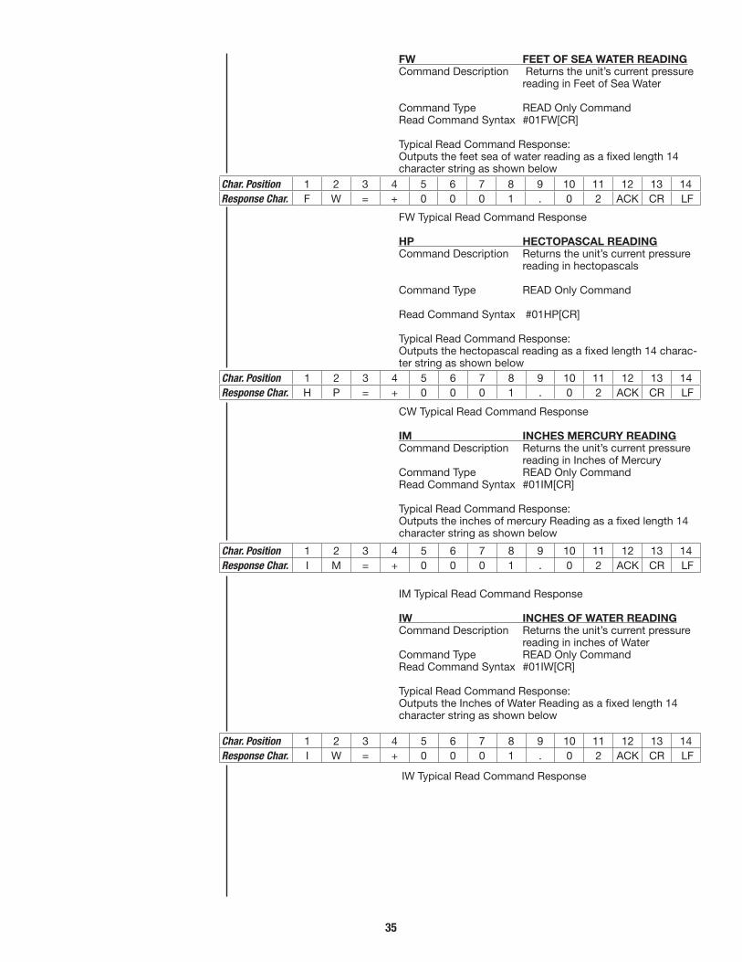
35
FW FEET OF SEA WATER READINGCommand Description Returns the unit’s current pressure
reading in Feet of Sea Water
Command Type READ Only CommandRead Command Syntax #01FW[CR]
Typical Read Command Response:Outputs the feet sea of water reading as a fixed length 14 character string as shown below
FW Typical Read Command Response
HP HECTOPASCAL READINGCommand Description Returns the unit’s current pressure
reading in hectopascals
Command Type READ Only Command
Read Command Syntax #01HP[CR]
Typical Read Command Response:Outputs the hectopascal reading as a fixed length 14 charac-ter string as shown below
CW Typical Read Command Response
IM INCHES MERCURY READINGCommand Description Returns the unit’s current pressure
reading in Inches of MercuryCommand Type READ Only CommandRead Command Syntax #01IM[CR]
Typical Read Command Response:Outputs the inches of mercury Reading as a fixed length 14 character string as shown below
IM Typical Read Command Response
IW INCHES OF WATER READINGCommand Description Returns the unit’s current pressure
reading in inches of WaterCommand Type READ Only CommandRead Command Syntax #01IW[CR]
Typical Read Command Response:Outputs the Inches of Water Reading as a fixed length 14 character string as shown below
IW Typical Read Command Response
Char. Position 1 2 3 4 5 6 7 8 9 10 11 12 13 14Response Char. F W = + 0 0 0 1 . 0 2 ACK CR LF
Char. Position 1 2 3 4 5 6 7 8 9 10 11 12 13 14Response Char. H P = + 0 0 0 1 . 0 2 ACK CR LF
Char. Position 1 2 3 4 5 6 7 8 9 10 11 12 13 14Response Char. I W = + 0 0 0 1 . 0 2 ACK CR LF
Char. Position 1 2 3 4 5 6 7 8 9 10 11 12 13 14Response Char. I M = + 0 0 0 1 . 0 2 ACK CR LF

36
KP KILOPASCALS READINGCommand Description Returns the unit’s current pressure
reading in KilopascalsCommand Type READ Only CommandRead Command Syntax #01KP[CR]Typical Read Command Response:Outputs the Kilopascal reading as a fixed length 14 character string as shown below
KP Typical Read Command Response
MB MILLIBAR READINGCommand Description Returns the unit’s current pressure reading in millibarsCommand Type READ Only CommandRead Command Syntax #01MB[CR]Typical Read Command Response:Outputs the millibar reading as a fixed length 14 character string as shown below
MB Typical Read Command Response
MM mm OF MERCURY READINGCommand Description Returns the unit’s current pressure
reading in mm of MercuryCommand Type READ Only CommandRead Command Syntax #01MM[CR]Typical Read Command Response:Outputs the mm of Mercury reading as a fixed length 14 character string as shown below
MM Typical Read Command Response
MP MEGAPASCAL READINGCommand Description Returns the unit’s current pressure
reading in MegapascalCommand Type READ Only CommandRead Command Syntax #01MP[CR]Typical Read Command Response:Outputs the Megaepascal Reading as a fixed length 14 char-acter string as shown below
MP Typical Read Command Response
NP NUMERIC VALUECommand Description Returns the unit’s current internal
CORRECTED 50,000 count value.This value includes the USER OFFSET AND SPAN. It does not include USER TARE.Command Type READ Only CommandRead Command Syntax #01NP[CR]Typical Read Command Response:Outputs the internal, corrected 50000 count value as a fixed length 10 character string as shown below
NP Typical Read Command Response(Note: NP does not precede the response)
Char. Position 1 2 3 4 5 6 7 8 9 10 11 12 13 14Response Char. M B = + 0 0 0 1 . 0 2 ACK CR LF
Char. Position 1 2 3 4 5 6 7 8 9 10 11 12 13 14Response Char. M P = + 0 0 0 1 . 0 2 ACK CR LF
Char. Position 1 2 3 4 5 6 7 8 9 10Response Char. + 0 0 0 1 0 2 ACK CR LF
Char. Position 1 2 3 4 5 6 7 8 9 10 11 12 13 14Response Char. M M = + 0 0 0 1 . 0 2 ACK CR LF
Char. Position 1 2 3 4 5 6 7 8 9 10 11 12 13 14Response Char. K P = + 0 0 0 1 . 0 2 ACK CR LF
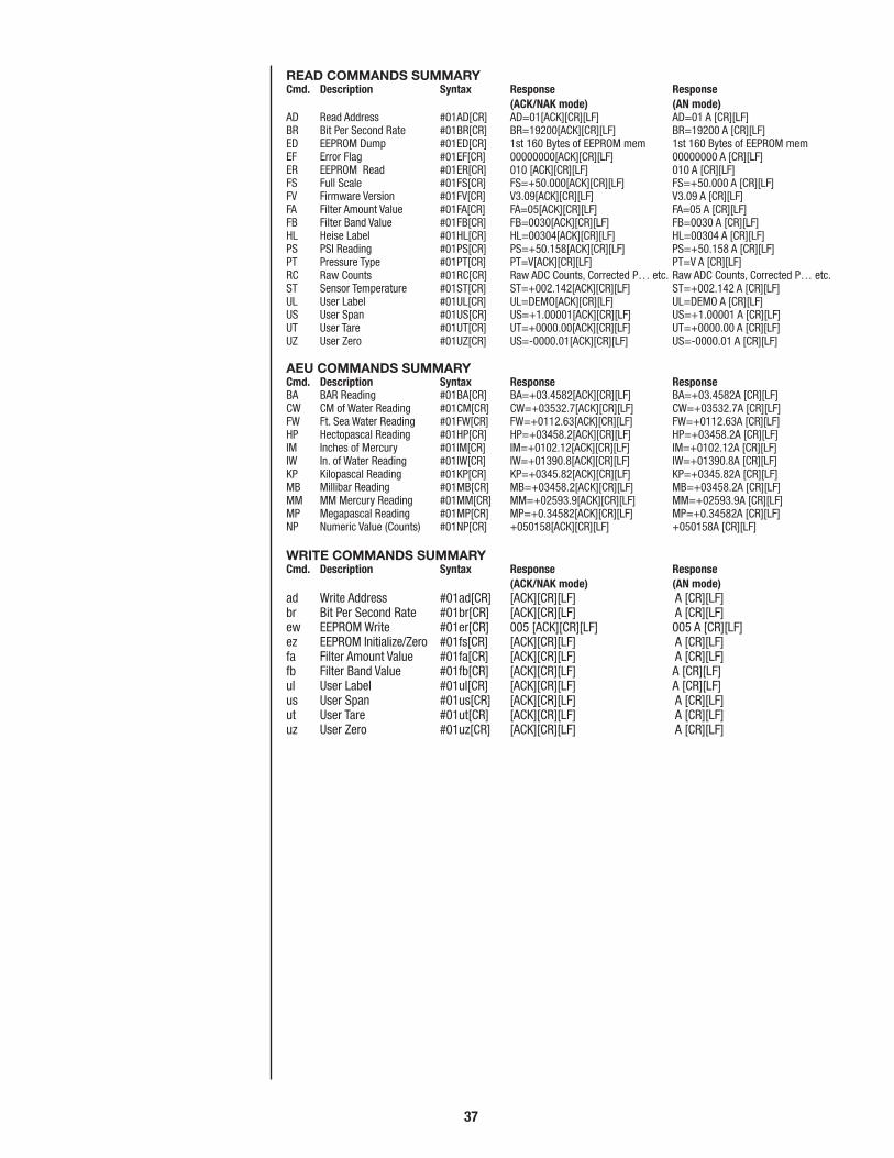
37
READ COMMANDS SUMMARYCmd. Description Syntax Response Response (ACK/NAK mode) (AN mode)AD Read Address #01AD[CR] AD=01[ACK][CR][LF] AD=01 A [CR][LF]BR Bit Per Second Rate #01BR[CR] BR=19200[ACK][CR][LF] BR=19200 A [CR][LF]ED EEPROM Dump #01ED[CR] 1st 160 Bytes of EEPROM mem 1st 160 Bytes of EEPROM memEF Error Flag #01EF[CR] 00000000[ACK][CR][LF] 00000000 A [CR][LF]ER EEPROM Read #01ER[CR] 010 [ACK][CR][LF] 010 A [CR][LF]FS Full Scale #01FS[CR] FS=+50.000[ACK][CR][LF] FS=+50.000 A [CR][LF]FV Firmware Version #01FV[CR] V3.09[ACK][CR][LF] V3.09 A [CR][LF]FA Filter Amount Value #01FA[CR] FA=05[ACK][CR][LF] FA=05 A [CR][LF]FB Filter Band Value #01FB[CR] FB=0030[ACK][CR][LF] FB=0030 A [CR][LF]HL Heise Label #01HL[CR] HL=00304[ACK][CR][LF] HL=00304 A [CR][LF]PS PSI Reading #01PS[CR] PS=+50.158[ACK][CR][LF] PS=+50.158 A [CR][LF]PT Pressure Type #01PT[CR] PT=V[ACK][CR][LF] PT=V A [CR][LF]RC Raw Counts #01RC[CR] Raw ADC Counts, Corrected P… etc. Raw ADC Counts, Corrected P… etc.ST Sensor Temperature #01ST[CR] ST=+002.142[ACK][CR][LF] ST=+002.142 A [CR][LF]UL User Label #01UL[CR] UL=DEMO[ACK][CR][LF] UL=DEMO A [CR][LF]US User Span #01US[CR] US=+1.00001[ACK][CR][LF] US=+1.00001 A [CR][LF]UT User Tare #01UT[CR] UT=+0000.00[ACK][CR][LF] UT=+0000.00 A [CR][LF]UZ User Zero #01UZ[CR] US=-0000.01[ACK][CR][LF] US=-0000.01 A [CR][LF]
AEU COMMANDS SUMMARYCmd. Description Syntax Response ResponseBA BAR Reading #01BA[CR] BA=+03.4582[ACK][CR][LF] BA=+03.4582A [CR][LF]CW CM of Water Reading #01CM[CR] CW=+03532.7[ACK][CR][LF] CW=+03532.7A [CR][LF]FW Ft. Sea Water Reading #01FW[CR] FW=+0112.63[ACK][CR][LF] FW=+0112.63A [CR][LF]HP Hectopascal Reading #01HP[CR] HP=+03458.2[ACK][CR][LF] HP=+03458.2A [CR][LF]IM Inches of Mercury #01IM[CR] IM=+0102.12[ACK][CR][LF] IM=+0102.12A [CR][LF]IW In. of Water Reading #01IW[CR] IW=+01390.8[ACK][CR][LF] IW=+01390.8A [CR][LF]KP Kilopascal Reading #01KP[CR] KP=+0345.82[ACK][CR][LF] KP=+0345.82A [CR][LF]MB Millibar Reading #01MB[CR] MB=+03458.2[ACK][CR][LF] MB=+03458.2A [CR][LF]MM MM Mercury Reading #01MM[CR] MM=+02593.9[ACK][CR][LF] MM=+02593.9A [CR][LF]MP Megapascal Reading #01MP[CR] MP=+0.34582[ACK][CR][LF] MP=+0.34582A [CR][LF]NP Numeric Value (Counts) #01NP[CR] +050158[ACK][CR][LF] +050158A [CR][LF]
WRITE COMMANDS SUMMARYCmd. Description Syntax Response Response (ACK/NAK mode) (AN mode)ad Write Address #01ad[CR] [ACK][CR][LF] A [CR][LF]br Bit Per Second Rate #01br[CR] [ACK][CR][LF] A [CR][LF]ew EEPROM Write #01er[CR] 005 [ACK][CR][LF] 005 A [CR][LF]ez EEPROM Initialize/Zero #01fs[CR] [ACK][CR][LF] A [CR][LF]fa Filter Amount Value #01fa[CR] [ACK][CR][LF] A [CR][LF]fb Filter Band Value #01fb[CR] [ACK][CR][LF] A [CR][LF]ul User Label #01ul[CR] [ACK][CR][LF] A [CR][LF]us User Span #01us[CR] [ACK][CR][LF] A [CR][LF]ut User Tare #01ut[CR] [ACK][CR][LF] A [CR][LF]uz User Zero #01uz[CR] [ACK][CR][LF] A [CR][LF]

38
ERROR CODES SUMMARY The DXD Transducer will return error codes if operating in “LEGACY mode” rather than a “nak” or “N”, for example where a user issues an incorrect command syntax, and when measurement values are out of specifications due to sensor damage, electrical problems etc. (Ref. pg. 38, MODE BYTE, for explanation of error response modes). The list below includes all error codes and their meanings.
Error Code DescriptionErr01 ADC No response within 300 ms.Err02 EEPROM write errorErr03 Incorrect numerical format for commandErr04 Calculated output over rangeErr05 ADC over range. Either channel 1 or 2Err06 Bad Pressure Type valueErr07 Illegal scale factor. Either channel 1 or 2Err08 ADC Reference Voltage Unstable or not
present
AEU SCALE FACTORS
Engineering Scale Unit Factor BA .0689476 CW 70.433 FW 2.2457 HP 68.9476 IM 2.03602 IW 27.730 KP 6.89476 MB 68.9476 MM 51.7149 MP .00689476 NP N/A
MODE BYTEBIT DXD Mode Byte (location 001 in
EEProm)
0 Calibration bit 0 = normal 1 = self cal mode 1 Error status character 0 = ACK/NAK 1 = A/N 2 end of line terminator, used in DXD mode only 0 = <cr> <lf> 1 = <cr> 3 echo bit 0 = command not echoed
1 = command echoed 4 Command Set Bit Don’t care in DXD firmware V3.XX 5 Error Status Character 1 = No error status character.
(Legacy Mode) This overrides bit 1 6 Free 0 = Error status character set in bit
1 is returned 7 ad noise test bit 0 = noise test not performed
1 = noise test performed(Factory default setting of MODE Byte = “0000000”)
Examples:DXD Firmware V3.XX
7 6 5 4 3 2 1 0 Bit positions
0 0 0 0 0 0 0 0
Bit 0 No A/D self calibration 1 ACK/NAK appended to response 2 <cr> <lf> is appended after ACK/NAK 3 no echo 4 DXD Command set 5 Error Status Character on 7 no noise test

39
7 6 5 4 3 2 1 0 Bit positions0 0 0 0 0 0 1 0
Bit 0 No A/D self calibration 1 A/N appended to response 2 <cr> <lf> if appended after ACK/NAK 3 no echo 4 DXD Command set 5 Error Status Character on 7 no noise test
7 6 5 4 3 2 1 0 Bit positions0 0 0 0 0 1 1 0
Bit 0 No A/D self- calibration 1 A/N appended to response 2 <cr> only 3 no echo 4 DXD Command set 5 Error Status Character on 7 no noise test
ENTERING the MODE BYTE setting into the DXD EEProm address location “001”:
The DXD EEProm locations, by design, are defined to contain numbers from 000 to 255. Setting the appropriate bit or bits in the MODE byte (address location “001”), therefore neces-sitates a conversion from the bit settings described above. Each one of the 8 bit locations (7 – 0) in the mode byte con-trols a function based on whether or not the bit is a ‘1’ or ‘0’. Each bit location represents a “binary weighting” , or decimal value dictated by its position in the byte. A ‘1’ in the position carries the full numeric value; a ‘o’ carries the value of 0. The weighting is as follows:
76543210 bit position numeric value00000001 = 1 00000010 = 2 00000100 = 400001000 = 800010000 = 1600100000 = 2201000000 = 6410000000 = 128
Example 1 If you want to set the “Error status character” to “A/N”, bit position 1 is set to a ‘1’. This has a numeric value of 2 (according to its position in the byte), so a “002” is written into address location “001”.
Example 2 If you want to turn the error status character off altogether, bit 5 must be set to a ‘1’, which has a numeric value of 32, therefore “032” is written into address location “001”.
Example 3 If you wish to have both “A/N” appended (bit 1), and the <cr> without the <lf> (bit 2), both bit 2 and bit 3 must be set to ‘1’, their respective numeric values are added together (2+4=6) and “006” is written into address location “001”. Note that if all of the bits are set to ‘1’ (actually an undefined state), the values of all of the bits added together equal 255. If no bits are set, then the total value equals 000.
To write information into EEProm address location “001” it is necessary to use the “ER” and “ew” library commands defined earlier in this document. Please be aware that when

40
using the “ew” command, a three digit value with leading zeros is required.
Examples: DXD Firmware V3.xx
0000000 no calibration, ACK/NAK appended to response, <cr> < lf> appended after ACK/NAK, no echo, DXD Command set, Error Status Char. On, no noise test.
00000010 same as above, only A/N appended instead of ACK/NAK 002
00000110 A/N appended, <cr> without <lf> 006
ATS Mode Byte
0 Cal Byte 0 = no calibration 1 = self cal. Mode 1 Error Status Don’t Care, it is disabled
Character 2 end of line Don’t Care, it is disabled
terminator 3 echo bit 0 = command not echoed 1 = command
returned 4 Command Must be 1 for ATS mode
bit set 5 Error Status Must be 0 for ATS mode
Character 6 Free 7 a/d noise test 0 = no noise test 1 = noise test
performed performed
Examples: ATS Variant
00010000 no calibration, no error status char. ATS 016 command set, no echo bit, no noise test
DETAILED EXPLANATION OF THE “FA” & “FB” COMMANDS
The DXD offers a powerful filtering algorithm to smooth out undesirable fluctuations or “noise” in the pressure source. The current filter values are applied to all available engineer- ing unit values. The filtering function has two components: Filter Amount and Filter Band. Separate values can be set for each, as described in the following section.
FA (Filter Amount)The filter amount determines the number of readings aver-aged in deriving the current pressure value. The range of values from 01 (off) to 5 (maximum) per the following table.
Filter Amount Values. FA Number of Values Readings 01 1 02 2 03 4 04 8 05 16To read the current value of FA of a transducer with address 01, send the following Read Command: #01FA[cr]The unit will respond with the following display: FA = 01 (or whatever the current value is set to)
To change the value of FA from its current value to 05 in a transducer with address 01, send the following Write

41
Command: #01fa05[cr]To confirm the change, re-send the initial Read Command.
FB (Filter Band)The filter band determines whether or not filtering is taking place and what percentage of the pressure span is being filtered (by the amount set in FA). Filtering is disabled if a pressure transient exceeds the value set for FB. This feature ensures that filtering will not occur if the transducer sees sud-den “spikes” or rapid rate of change in the pressure source.
To read the current value of FB for a transducer with address 01, send the following read command: #01FB[cr]The unit will respond with the following display: FB=0059 (or whatever the current value is)
The minimum value is 0002 and maximum is 9999 which represents an incremental value of ±0.001% of full scale. Therefore the maximum bandwidth is ±10% of full scale. To change the value of FB, a four character value must be included in the FB Write Command. The following table pro-vides an abbreviated listing of possible values and their effect on the bandwidth.
Filter Band Values FB Effect as % Values of Full Scale 0001 0.000% FS 0002 0.002% FS 0050 0.05% FS 0250 .25% FS 1000 1.0% FS 5000 5.0% FS 9999 9.999% FS
To change the current value of FB from its current value of 0250 (±0.25%) in a transducer with address 01, send the fol-lowing Write Command: #01fb0250[cr]To confirm the change, re-send the initial Read Command
NOTE: Due to resolution limitations in the math package it is necessary to add one count more to the FB value to obtain the expected % of full scale counts as anticipated, in some cases.
Example: #01fb0030 should set the FB to .03% of 50,000, set in terms of counts, or 15 counts. In actuality, due to resolution issues, the count is only set to 14. To get the full 15 counts, the command needs to have one count added (.001%): #01fb0031This will set the full 15 counts for FB.
As an added feature, the actual % of 50,000, set in terms of counts, can be read from the EEProm in the DXD by using the ER command at locations 158 (upper byte) and 159 (lower byte):
To read the FB in terms of counts from a transducer with address 01, with a FB value set to 003, send the following Read Command: #01ER159[cr]
The response will be: 015

42
ALTERNATE ENGINEERING UNITS (AEU) EXPLAINED
The following table shows the relationship between pressure in psi and pressure displayed in the available alternate engi-neering units in the DXD. Note that at pressures above zero it is possible for a selected engineering unit to display well over the normal 50,000 count limit defined for the DXD. For this reason, selection of the sensor range and AEU need to be matched accordingly to limit the resolution of the display below the 50,000 count resolution limit. As can be seen in the example table below, resolutions above and below the maxi-mum limit can be displayed. These highlighted measured values adhere to display “rules” as defined in the statements and examples below the table.
UPDATE RATE MODIFICATIONSThe DXD has a “Delta Sigma” Analog to Digital Converter which gives it the capability of modifying its filtering profile by the adjustment of data in its non-volatile memory. This is done by writing to the DXD’s memory via the “ER” and “ew” commands. Below is a table that lists the necessary informa-tion to change the update rate of the DXD from 15 to 100
AEU Measured Measured AEU Neumonic Scaler psi AEU Definitions
BA .0689476 5002.5 344.90 Bar
CW 70.433 4055.3 285628 cm water
FW 2.2457 4055.3 9107 feet of water
HP 68.9476 4051.1 279314 Hecto Pascal
IM 2.03602 4033.7 8212 In. Hg
IW 27.73 4014.1 111311 In. Water
KP 6.89476 3980.8 27446 Kilo Pascal
MB 68.9476 3956.6 272798 Mili Bar
MM 51.7149 3938.9 203700 Mm Hg
MP .00689476 5002.5 34.490 Mega Pascal
NP N/A 5000.0 50000 Numeric PSI
RULE 1 – The display pressure is not to exceed 50,000 counts of resolution unless the true value of the number is altered in not doing so.RULE 2 – Numbers cannot be added to the right of the decimal point if their addition causes numbers to exceed the 50,000 count limit.RULE 3 – Displayed numbers over 50,000 counts will not increment in single digits. The will increment by a value calculated by the full scale value divided by 50,000.
1st Rule example, AEU = mm Hg (MM):3938.9 PSI is displayed as 203700 mmHG. This is over the 50,000 count limit because truncating the number down to 20370 (below the 50,000 count limit) changes the true value of the number.
2nd Rule example, AEU = in Hg (MM):4014.1 PSI is displayed as 8212 in Hg. Adding .6 to the in. Hg value (8212.6) pushes the value over 50,000 counts. Removing the .6 does not alter the value of the number, it just reduces the amount of resolution.
3rd Rule example, AEU = mmHg (MM):258575/50,000 = 5.1715, therefore the display will incre-ment in steps of approximately 5 counts.

43
Mili seconds calculated
DXD EE Prom Address Locations
Total Update Time Total Time (-) tx addr 019 addr 020 addr 035 addr 036 @ 115K baud & rx @ 115.2 K
013 130 013 130 15 13.3507 043 082 16 082 20 18.3507 009 112 16 082 25 23.3507 013 128 16 082 30 *28.3507* 014 016 044 210 35 33.3507 014 144 073 082 40 38.3507 015 016 012 080 45 43.3507 015 160 016 080 50 48.3507 019 176 016 080 55 53.3507 023 192 016 080 60 58.3507 027 208 016 080 65 63.3507 031 224 016 080 70 68.3507 035 240 016 080 75 73.3507 040 000 016 080 80 78.3507 044 016 016 080 85 83.3507 048 032 016 080 90 88.3507 052 048 016 080 95 93.3507 056 064 016 080 100 98.3507 Vp SF word locations Vi SF word locations
*Manufacturing Default Value
For your reference, the following table lists the available baud rates, bit rates, and the time it takes to send one complete ASCII character, 10 bits in length. It also provides the time it takes to send a “PS” command from the host computer to the DXD, and the response to the “PS” command.
ms. in increments of 5 ms. The “Total update time” column (under mili seconds) represents updates which include transmit and receive communications for a “PS” command at 115.2 K baud. The column to the right of that represents update rates without any communication time factored in. To find the actual turn-around time of command, update, and a response, use the last column for the A/D update time, and add the transmit and receive time required, based upon the baud rate operated at, and the length of the transmit and receive “strings”.
Addresses are selected using the “ER” command, and data is written to the selected address using the “ew” command
1 Start, 7 data Actual (#01PS<cr>) Device response 1 Stop, 1 parity Character Shortest to press val. BAUD Char. length length used command length Request -13 RATE Bit time 10 bits is 10 -6 characters Characters
mili seconds mili seconds mili seconds mili seconds mili seconds
1200 0.83333 0.83333 0.83333 50.000 108.3333
2400 0.41667 0.41667 0.41667 25.000 54.1667
4800 0.20833 0.20833 0.20833 12.500 27.0833
9600 0.10417 0.10417 0.10417 6.2500 13.5417
19200 0.05208 0.05208 0.05208 3.1250 6.7708
38400 0.02604 0.02604 0.02604 1.5625 3.3854
57600 0.01736 0.01736 0.01736 1.0417 2.2569
115,200 0.00868 0.00868 0.00868 0.5208 1.1285

44
Addendum ASYNCHRONOUS READ (Sr) Command Specifications for DXD Firmware Revision 3.31 & Higher
The DXD “Synchronous Read” command structure is defined to be a series of two or more commands, depending upon the number of units on the serial bus.
The process begins with the host computer sending the GLOBAL command “#**Sr”. This command instructs ALL units on the bus to do a pressure conversion and store the results in a buffer (this buffer is called the Sr Buffer). Note that this is a blind command and there is no response from any of the units on the bus.
The host must then “time out” for a predetermined update time determined by the update rate setting of the DXD (13 ms at the fastest update rate of the DXD).
After this delay, the Host must query each individual DXD on the bus by using its unique address using the proper syntax. This will retrieve the synchronous pressure reading stored in the Sr buffer. Retrieving the stored synchronous pressure reading is accomplished using the following syntax;
“#01Ps” or “#01Np”
This will send the pressure reading from the buffer in terms of PSI or Numerical Pressure. The update time required to perform either of these two pressure readings (discounting transmit and receive times) in less than 200 microseconds. Substituting an available alternate engineering unit (AEU) in place of “Ps” or “Np” is also available but at the expense of an additional 300 microseconds to the retrieval process. Note that the proper syntax for an AEU in synchronous read mode is the same as that for Ps or Np, that is an Upper Case char-acter followed by a Lower Case character.
After reading the pressure information from the Sr buffer, the buffer is cleared. To transmit another reading from the Sr buffer it is necessary for the host to once again start the process by sending another “Sr” command followed by the previously mentioned timeout, and then request the informa-tion from the Sr buffer once again.
Requests for information from an empty Sr buffer will result in the generation of a syntax error from the addressed device.
It is acceptable to initiate another “Sr” command sequence if the Sr buffer is currently full. No syntax error will be gener-ated and the new request for a synchronous pressure update will be honored. The new pressure update information will replace that information currently held in the Sr buffer.
If the “Sr” command is followed by a standard request for a pressure update, ie. “#01PS”, the Sr buffer will be cleared, a pressure update will be performed, and the requested pres-sure will be shipped out to the interface bus.

45
NOTE: Numbers in parentheses after commands are the reponnse times of the transducer to that particular command.
SYNCHRONOUS READ INITIALIZE COMMANDCommand Description Syntax Response Response (ACK/NAK mode) (A/N mode)Sr Start Synchronous Read #**Sr BLIND RESPONSE BLIND RESPONSE
SYNCHRONOUS AEU COMMANDS SUMMARYCommand Description Syntax Response Response (ACK/NAK mode) (A/N mode)Ba(400µs) BAR Reading #01Ba[CR] Ba=+03.4582[ACK][CR}[LF] Ba=+03.4582[A][CR}[LF]Cw(400µs) CM of Water Reading #01Cw[CR] Cw=+03532.7[ACK][CR}[LF] Cw=+03532.7[A][CR}[LF]Fw(400µs) Feet Sea Water Reading #01Fw[CR] Fw=+0112.63[ACK][CR}[LF] Fw=+0112.63[A][CR}[LF] Hp(400µs) Hectopascal Reading #01Hp[CR] Hp=+03458.2[ACK][CR}[LF] Hp=+03458.2[A][CR}[LF]Im(400µs) In. of Mercury Reading #01Im[CR] Im=+0102.12[ACK][CR}[LF] Im=+0102.12[A][CR}[LF]Iw(400µs) In. of Water Reading #01Iw[CR] Iw=+01390.8[ACK][CR}[LF] Iw=+01390.8[A][CR}[LF]Kp(400µs) Kilopascal Reading #01Kp[CR] Kp=+0345.82[ACK][CR}[LF] Kp=+0345.82[A][CR}[LF]Mb(400µs) Millibar Reading #01Mb[CR] Mb=+03458.2[ACK][CR}[LF] Mb=+03458.2[A][CR}[LF]Mp(400µs) Megapascal #01Mp[CR] Mp=+0.34582[ACK][CR}[LF] Mp=+0.34582[A][CR}[LF]Np(200µs) Numeric Value #01Np[CR] +050158[ACK][CR}[LF] +050158[A][CR}[LF]

46
ADDENDUM BDXD ____ ATS VARIANT DEFINITION
Data Structure; ATS DXD 8 data bits 7 data bits 1 Stop bit 1 stop bit No Parity bit Even parity
This data structure will be turned on and off using the mode byte in eeprom at address location 001. Bit 4 of this byte will define the data format. A “0” will define DXD format (7,e,1), and a “1” will define ATS format (8,n,1).
Two customer commands are added to the command struc-ture. They are “#01cfDXD” & “#01cfATS”. These commands set the DXD into ATS or DXD data format. The data formats are such that the DXD system will respond to each of these commands regardless of the mode of operation it is in at the time of the command. These commands also effect bits 2 (end of line terminator) & 5 ( error status) of the mode byte. In DXD mode bits 2,4, & 5 will be “0”; end of line terminator set to “cr” “lf”, format bit set to DXD, error status bit set to ack/nak. In ATS mode these bits will be set to “1” ; end of line ter-minator set to “cr” only, format bit set to ATS, & error status bit set to no error response.
Note, that if bit 4 is set to DXD, bit 5 (error status) reverts to the standard DXD definition of error status handling.
COMMAND STRUCTURE IN ATS MODE (#01cfATS)Be advised that letters in < >, in command and response strings, indicate non-printable ASCII characters.
1. #01PS<cr> (Return pressure in PSI, same structure as DXD)
The response required to this command is as follows;13 characters long including a carriage return (cr).PS=<sp>+000.000crNote: The ASCII space (sp) between the equal and polarity sign. There will always be a decimal point in the return string.
2. #01NP<cr> (Return pressure in 0-50,000 counts, no pre-ceding label).
The response required to this command is as follows;
The response is in terms of 50,000 counts, the max resolu-tion of the device. In this case the response string would be.spspspsp+0500.00cr
3. #01TA<cr> ( Return tare value) The response required to this command is as follows; 17 characters long including a carriage return (cr).TA=spspspspsp+000.000cr
4. #01UZcr ( Return the user zero value) The response required to this command is as follows; 17 characters long including a carriage return (cr).UZ=spspspspsp+000.000cr
5. #01UScr ( Return the user zero value) The response required to this command is as follows; 17 characters long including a carriage return (cr).US=spspspspsp+1.00000cr

47
6. #01taCODE+000.000cr (Write a user TARE value) a. There is no response string to this command. b. CODE is a 4 digit access code that the ATS required for certain operations. In this case the access code will be always defaulted to “CODE”. c. The number for tare will be sign, decimal point, six
digits, followed by a carriage return. d. Tare application in ATS and DXD is the same.
7. #01uzCODE+000.000cr (Write a user ZERO value) a. There is no response string to this command. b. CODE is a 4 digit access code which the ATS required
for certain operations. In this case the access code will be always defaulted to “CODE”.
c. The number for zero will be sign, decimal point, six digits, followed by a carriage return.
d. User zero application in ATS and DXD is the same.
8. #01usCODE+1.00000cr (Write a user SPAN value) a. There is no response string to this command. b. CODE is a 4 digit access code which the ATS required
for certain operations. In this case the access code will be always defaulted to “CODE”.
c. The number for span will be sign, decimal point, six digits, followed by a carriage return.
d. User span application in ATS and DXD is the same.
9. #01cfATS (Change data format to ATS mode, 8,n,1) This command is blind, and will have no response string regardless of present mode of operation.
10. #01cfDXD (Change data format to DXD mode, 7,e,1 This command is blind, and will have no response string regardless of present mode of operation.
ADDITIONAL DXD COMMANDS SET TO ATS COMPATIBLE PROTOCOL
Command ListBR, brUZ, uz (already considered by customer requirements)FSPS (already considered by customer requirements)ADad
#01BRcr (Read the current baud rate – 8 possible) The response required to this command is as follows;
BR=spspspspspspspspsp9600cr (9 spaces) BR=spspspspspspsp115200cr (7 spaces)
1, For 9600 baud, the 9 ASCII spaces are stuffed to simulate the expected response from an ATS, 17 characters includ-ing the carriage return. Different numbers of characters in the baud rate definition will require changing the number of spaces stuffed so that the response string is always 17 characters long.
#01FScr (Read the full scale value of the DXD) The response required to this command is as follows.
FS=+0100.00cr (12 characters including the carriage return) (This is the same as the standard DXD)
#01ADcr (Read the current address of the DXD) The response required to this command is as follows;
AD=spspspspspspspspspspsp01cr

48
1, The 11 ASCII spaces are stuffed to simulate the expected response from an ATS, 17 characters including the carriage return.#01br1200cr Change the baud rate of the DXD#01br2400cr#01br4800cr#01br9600cr #01br19200cr#01br38400cr#01br57600cr#01br115200cr
1, There is no response string to this command.2, This is the same command as in standard DXD except that the baud rate selections differ.
#01ad01cr (Change the address of the DXD)1, There is no response string to this command.2, This is the same command as in standard DXD except that the wild card “**” is not utilized.
DXD RECEIVE TO TRANSMIT DELAY CAPABILITY –Rev. 3.36 Firmware & higher.
PURPOSE; Delay the response of the DXD to commands from the host computer to allow operation of the 485 interface in half duplex (2 wire) mode.
EXPLANATION; If the system is set up in half duplex (2 wire mode), the transmit and receive lines of the 485 interface are tied together. Both the DXD and the host computer control the activation of their respective transmitters, turning them on and off as required. In the off state, the transmitter output is “tri-stated” (high output impedance), assuring that the receiver lines are not interfered with when data is placed on them from either the DXD, or the host. If the DXD responds to a command faster than the HOST can release it’s trans-mit line, the information going into the host’s receiver will be “garbled” because it’s transmitter is causing contention on it’s own receiver lines. DXD Rev 2.15 firmware can operate in half duplex because it will ALWAYS do a pressure update (15 ms) regardless of the command received. This delay is enough to allow the HOST to release it’s transmit lines. All higher revisions of the DXD (over 2.15) have an added feature which saves time in data turn around for commands which don’t require a pres-sure update. Unfortunately, this improved turn around time is too fast for the HOST system, and the data coming from the DXD is compromised. Revision 3.36 of the DXD firmware has addressed this issue by adding the capability of a program-mable delay between receipt of a command by the DXD and it’s response. The delay can be set between 0 and 208 mili seconds.
IMPLEMENTATION; Address location “013” in the DXD eeprom is reserved for the programming of the Rx/Tx delay of the DXD. The span of data which is defined for this location is from “000” to “255”. The resolution of the delay increments is 820 micro seconds. “000” equates to 0 delay, and “255” equates to 208 mili-sec-onds delay. Numbers between “000” and “255” add 820 micro second linear increments to the delay. To write data to address location “013”, use the “ER” read command followed by the “ew” write command.

49
PAGE INTENTIONALLY BLANK

50
For the name and location of the nearest sales representative, contact the Stratford sales office.
All specifications are subject to change without notice. All sales subject to standard terms and conditions. © 2016 Ashcroft Inc. 10/16 I&M002-10106 Rev. C
Visit our web site at www.heise.com
World Headquarters
Ashcroft Inc. 250 E. Main StreetStratford, CT 06614-5145 U.S.A.Tel: (203) 378-8281Fax: (203) 385-0402
(Domestic)Fax: (203) 385-0357
(International)email: [email protected] www.heise.com

51
All specifications are subject to change without notice. All sales subject to standard terms and conditions. © 2016 Ashcroft Inc.10/16 I&M002-10107
DXD Setup Utility User Manual

52

53
TABLE OF CONTENTS SECTION TOPIC PAGE1.0 About This Manual .................................................................................................... 541.1 Scope ....................................................................................................................... 541.2 Purpose .................................................................................................................... 541.3 Intended Audience.................................................................................................... 541.4 Notation Conventions ............................................................................................... 542.0 Getting Started ......................................................................................................... 542.1 Installing the Utility via the Data Stick ...................................................................... 542.2 DXD w/ USB interface, Communications Setup ...................................................... 542.3 If the DXD w/USB Fails to Enumerate ...................................................................... 552.4 DXD Setup Utility Overview ...................................................................................... 552.5 Navigation ................................................................................................................. 552.5.1 Menu Navigation ....................................................................................................... 552.5.2. Mouse Navigation ..................................................................................................... 552.5.3. Keyboard Navigation ................................................................................................ 562.6 Menu ......................................................................................................................... 562.7 Operation .................................................................................................................. 582.7.1. New Transducers ...................................................................................................... 583.0 Windows ................................................................................................................... 583.1 Communication Properties ....................................................................................... 583.1.1. Port ........................................................................................................................... 593.1.2. Baud Rate ................................................................................................................. 593.1.3. Data Bits ................................................................................................................... 593.1.4. Parity ......................................................................................................................... 593.1.5. Stop Bits ................................................................................................................... 593.2 Find DXD .................................................................................................................. 593.3 Normal Speed Monitor ............................................................................................. 603.3.1. Selection of Pressure Transducer and Pressure Units ............................................. 613.3.2. Monitoring at Pressure and Temperature ................................................................. 613.3.3. Logging ..................................................................................................................... 623.3.4. Calibration ................................................................................................................ 633.3.4.1 Tare/Remove Tare ..................................................................................................... 633.3.4.2 Zero .......................................................................................................................... 633.3.4.3 Span ......................................................................................................................... 633.4 High Speed Monitor ................................................................................................. 643.4.1. Selection of Pressure Transducer and Pressure Units ............................................. 653.4.2. Logging ..................................................................................................................... 653.4.3. Trend Viewing ........................................................................................................... 653.5 Utility Diagnostics ..................................................................................................... 663.6 Utility Command and Query ..................................................................................... 673.7 Read Commands ...................................................................................................... 683.8 Write Commands ...................................................................................................... 684.0 Files .......................................................................................................................... 694.1 Normal Speed Data File............................................................................................ 694.2 High Speed Data File ................................................................................................ 70

54
This manual explains the features and use of the Ashcroft Instruments DXD Setup Utility.
Although operation of the Ashcroft Instruments DXD Setup Utility is intuitive, this manual provides more definition to enhance its use.
Users of the Ashcroft Instruments DXD digital pressure trans-ducer and DXD Setup Utility
Convention UseBold Indicates topic titles and sub-titlesItalics Indicates file paths and names, menu items, and
document names“quotes” Reference to control or indicator named as indi-
cated by the text within the quotes<greater-th an/less-than> Text within the greater-than/less-
than characters indicates key press{braces} Text within the braces indicates a keyboard text
entry or mouse selection
The DXD Setup Utility and support files are supplied on a USB memory stick that auto-starts the installation procedure when inserted into a USB port of any computer with a Micro-soft Windows operating system, XP or higher. This applica-tion runs on a Microsoft Windows operating system only. If the application does not auto-install, see 2.1 below
1 If the Utility fails to Auto Run when the provided data stick is installed you will be required to do the following:
a, Navigate to the installed data stick using Windows Explorer
b, Open “DXD Setup Utility Installer” d, Click on “Volume” e, Double click on “setup.exe” f, follow the prompts
1, The USB interface is a virtual communication port to the Windows operating system. Each DXD will be assigned its own Communication port number unlike the RS-232 and RS-485 interfaces which all communi-cate over one communication port.
In order to insure proper communications the operator is required to set the DXD software utility to the Com-munication port assigned by Windows to the DXD after it is inserted into the USB port. To accomplish this, do the following:
a, Connect the DXD into a USB port on the PC and make sure it enumerates (PC will signify this with an audio signal).
b, Navigate to the device manager on your particular Windows system and “click” on Communication Ports.
c, See which Communication port Windows assigned to the DXD.
d. In the DXD utility, set the “Comm Port” to match the Windows assigned Communication port
e. To communicate to the DXD, you will still need to address each DXD with its unique two digit address. (Go to the “Home” pull down, select “Find DXD(s)”, and then select “Single Transducer” in the “Type of Search” box, then click on “Poll Bus”. This will search for and then display the address of the single DXD in the system and its baud rate. (or see section 2.7.1 for an alternate method)
NOTE: Due to the present structure of the “Set Up
SECTION 1.0 ABOUT THIS MANUAL
SECTION 1.1 SCOPE
SECTION 1.2 PURPOSE
SECTION 1.3 INTENDED AUDIENCE
SECTION 1.4 NOTATION CONVENTION
SECTION 2.0 GETTING STARTED
SECTION 2.1 INSTALLING THE UTILITY
SECTION 2.2 DXD w/USB INTERFACE – COMMUNICATIONS SETUP

55
Utility” software, unlike with RS-232 or RS-485, only one DXD w/ USB can be addressed at a time. In this case, the utility is used to set up the DXD for use with other software supplied by the end user.
1, If the correct driver for the interface IC inside the DXD doesn’t reside on the user’s system it will be necessary to either install it from the provided ASHCROFT/HEISE data stick or download it from the IC manufactures website.
2, The IC is manufactured by “FTDI”. The IC being used is “RS232R”
Use the DXD Setup Utility application (splash screen shown in Figure 1) with the Heise DXD Digital Pressure Transducer. Features include communication properties specification, temperature and pressure monitoring, high-speed pressure trending, calibration, searching for connected transducers with unknown address and baud rate, diagnostics, terminal window, and data logging.
Figure 1
Figure 1Use the mouse and/or keyboard to navigate within the DXD Setup Utility. Information contained here assumes the user is familiar with basic navigation within the Microsoft Windows environment.
Use mouse or keyboard, as described in sections 2.5.2 and 2.5.3 below, to navigate and select menu items. Menu choices are shown and described below
The main menu at the top of the DXD Setup Utility window is shown in Figure 2 below. Use this menu to select available screens that are described in greater detail in Section 3.
Figure 2
Move the mouse pointer over the menu item, front panel buttons (see Figure 1), or accept or cancel button where appropriate, then click to select. Some menu items contain sub-menu items that show once the top-level menu item is selected. Move the mouse pointer over a control and click to select and change its value.<Alt> combined with the first letter of the top-level menu item selects the top-level menu item. Use the arrow keys to navi-gate within the menu once the menu is selected.
SECTION 2.3 IF THE DXD FAILS TO ENUMER-ATE WHEN IT IS PLUGGED INTO A USB PORT
SECTION 2.4 DXD SETUP UTILITY OVERVIEW
SECTION 2.5.1 MENU NAVIGATION
SECTION 2.5.2 MOUSE NAVIGATION
SECTION 2.5 NAVIGATION

56
SECTION 2.6 MENUS
Use the <Enter> key to select a highlighted menu item or accept the value of a control.
Use the <Tab> key to step through selection of each of the controls on the window.
When a list type control is selected, use the up and down arrow keys to scroll through the selections. When a number or string control is selected, use the keyboard to enter the number or string as appropriate.
Use the keyboard shortcuts listed for some of the menu items as follows:<Ctrl><P> to print window<Ctrl><Q> to exit the DXD Setup Utility application<Ctrl><H> to show context help for information on the con-trols and indicators<F1> to show the help documentation you are currently reading.
These shortcuts are listed to the right of the corresponding menu items in the menus as shown in Figure 3, Figure 4, and Figure 8.
Figure 2 and the following six figures show all menu selec-tions in the DXD Setup Utility.
The File menu choices include Print Window… and Exit as shown in Figure 3. Print Window… opens the Microsoft Win-dows print dialog for printing the current DXD Setup Utility screen to the printer of choice. Choose landscape or portrait as appropriate for the screen to be printed. Exit shows a con-firmation dialog for exiting the DXD Setup Utility application.
Figure 3
The Home menu choice does not contain any sub-menu items, but when selected, returns to the main splash screen shown in Figure 1.
The Edit menu shown in Figure 4 provides the MS Windows copy and paste functionality. Select the text in a control to be copied, select Edit>>Copy to copy to the Windows clip-board, click the text area of the control to which to paste the clipboard data, and finally, select Edit>>Paste to paste from the Windows clipboard.
Figure 4
The single Configuration menu choice is Communication Properties as shown in Figure 5. This selection opens the communication properties window for setting the “Port” number, “Baud Rate,” number of “Data Bits,” “Parity,” and number of “Stop Bits.”
SECTION 2.5.3 KEYBOARD NAVIGATION

57
Figure 5
The Monitor menu choices include Find, Normal Speed, and High Speed as shown in Figure 6. The Find selection opens a window for searching the specified port for connected transducers. The Normal Speed selection opens a window for monitoring 1 to 99 transducers (RS-232 or RS-485 for multiple transducers only, single USB only communication available ), at a rate no faster than four samples/second, on a choice of table, gauge, or digital indicator. This window also provides logging to file, tare/remove tare, zero, and span capabilities. The High Speed selection opens a window for monitoring a single transducer at the fastest rate possible in the Microsoft Windows operating system. This window also provides for logging to file.
Figure 6
The Utility menu choices include Diagnostics and Command and Query as shown in Figure 7. The Diagnostics selection opens a window for retrieving settings from connected trans-ducers, and provisions for saving and restoring EEPROM data. The Command and Query selection opens a window for retrieving or setting any of the DXD pressure transducer parameters.
Figure 7
The Help menu choices are “Show Context Help,” “DXD Setup Utility Help,” “DXD Setup Utility Manual,” “About DXD Setup Utility,” and as shown in Figure 8. The “Show Con-text Help” selection toggles between showing and hiding a floating window that displays context-sensitive help for any control or indicator over which the mouse pointer is moved. The “DXD Setup Utility Help” selection opens the WinHelp DXD_SETUP_UTILITY.HLP file for the DXD Setup Utility. The “DXD Setup Utility User Manual” selection opens the DXD Setup Utility User Manual.pdf you are currently reading. The “About DXD Setup Utility” selection opens a floating window with contact information for Ashcroft Instruments and the version number of the DXD Setup Utility.
SECTION 2.6 MENUS (CONT.)

58
Figure 8
The operation of each window in this application is described in detail in Section 3 of this document. For information on connecting DXD pressure transducers to your computer for use with the DXD Setup Utility software, please consult with the DXD Series – Precision Digital Pressure Transducer Instal-lation and Operating Instructions.
When connecting new transducers for the first time, connect one at a time until each is configured with a unique address, and communication properties are configured.
The best procedure for configuring new transducers is: 1. Connect one transducer 2. Run DXD Setup Utility application 3. Select Configuration>>Communication Properties 4. Set “Port” to the appropriate number (note: for the
USB option reference section 2.1 of this manual for instructions to determine the communications port assigned by Windows to the device.)
5. Select Monitor>>Find 6. Select {Single Transducer} for “Type of Search” 7. Click “Poll Bus” 8. Note address and baud rate returned from connected
transducer 9. Select Configuration>>Communication Properties10. Select returned baud rate in “Baud Rate” control11. Confirm “Data Bits” is set to {7}, “Parity” is set to
{Even}, and “Stop Bits” is set to {1.0} (These are the standard factory default settings)12. Select Utility>>Command and Query13. Enter noted “DXD Address” (step eight)14. Select {Write Unit Address} in “Command” control and
enter “Desired DXD Address” in the control that shows to the right
15. Click “Send Command” button16. Select {Write Bit Per Second Rate} in “Command”
control and select “Desired Bit Per Second Rate” in control that shows to the right
17. Click “Write Command” button18. Repeat for each new transducer and assign a unique
address for each. (Note: They all should have the same baud rate.)
This section describes in detail the use of the various win-dows in the DXD Setup Utility.Note: For systems using the DXD transducer with the optional USB interface, please refer to section 2.1 for proper communication set-up.
This window is accessed via menu selection Configura-tion>>Communication Properties. Use the controls on this window, shown in Figure 9, to set the properties used for communicating with the DXD pressure transducers con-nected to the specified port. Settable parameters are “Port,” “Baud Rate,” “Data Bits,” “Parity,” and “Stop Bits”. Note that these are not factory defaults. See section below Figure 9 for factory defaults
SECTION 2.6 MENUS (CONT.)
SECTION 2.7 OPERATION
SECTION 2.7.1 NEW TRANSDUCERS
SECTION 3.0 WINDOWS
SECTION 3.1 CONFIGURATION>> COMMUNICATION PROPERTIES

59
Figure 9
The port identifies the serial communications port to which the DXD pressure transducer(s) is(are) connected. To find available ports, navigate to the Device Manager in windows…, and expand the Ports (COM & LPT) item. Available choices for port are 1-256.
The baud rate is the maximum rate, in bits per second (bps), that you want data to be transmitted through this port. The DXD pres-sure transducer with which you are commu-nicating must have the same setting that you choose here. Available choices for baud rate are shown in the graphic to the right. Factory default is 19200 bits per second.
The number of data bits you want to use for each character that is transmitted and received. The DXD pressure transducer with which you are communicating must have the same setting that you choose here. Avail-able choices for data bits are shown in the graphic to the right.
The type of error checking you want to use for the selected port. The DXD pressure transducer with which you are communi-cating must have the same setting that you choose here. Available choices for parity are shown in the graphic to the right.
The time between each character being transmitted (where time is measured in bits). Available choices for stop bits are shown in the graphic to the right.
The find window, shown in Figure 10 provides search capa-bilities for one or more connected DXD pressure transducers for which any combination of addresses and baud rates are unknown.
SECTION 3.1.1 PORT
BAUD RATE
DATA BiTS
PARiTY
SECTION 3.1.3 DATA BITS
SECTION 3.1.4 PARITY
SECTION 3.1.5 STOP BITS STOP BiTS
SECTION 3.1.2 BAUD RATE
SECTION 3.2 FIND

60
The current communication properties are shown at the bottom right of the window. They are shown in order of com-munication port (COM1), baud rate (115200), parity (Even), number of data bits (7), and number of stop bits (1).
Select the “Type of Search,” either {Single Transducer} or {Multiple Transducers} from the list. Make sure only one transducer is connected when searching for a single trans-ducer, as a wild card (**) is used in place of a unit address when sending the query. If multiple transducers are con-nected when searching for a single transducer, the returned data may be garbled. If {Multiple Transducers} is selected, any number of transducers with unique addresses from 1 to 99 may be connected (except for DXD w/ USB option). Click the “Poll Bus” button to start the search after the type of search is selected. The text on this button changes to “Cancel” after clicked.
The “Search Status” updates as transducers are searched for and provides a summary when complete or when “Cancel” is clicked.
As transducers are found, their address, Heise label (serial number), user label, firmware revision, range, and baud rate are added to the next row in the table. When the table is filled to the bottom of the window, a scroll bar becomes visible for scrolling through all found transducers.
Figure 10
The normal speed monitor window, shown in Figure 11, allows monitoring of pressure and temperature of one or more DXD pressure transducer(s). Access this window via menu selection Monitor>>Normal Speed. The window is broken down into four areas: selection of pressure trans-ducer and pressure units, logging, calibration, and monitor. The rate of retrieval of new values from the transducer(s) is dependent on how many transducers have been selected for monitoring and how many processes are currently running on the computer and consuming resources. The table is updated one transducer at a time. Pressure can also be displayed on a dial gauge or digital indicator as described in section 3.3.2. The current communication properties are shown at the bottom right of the window. They are shown in order of com-munication port (COM1), baud rate (115200), parity (Even), number of data bits (7), and number of stop bits (1).
SECTION 3.3 MONITOR>>NORMAL SPEED
SECTION 3.2 FIND (CONT.)

61
SECTION 3.3.1 SELECTION OF PRESSURE TRANSDUCER AND PRESSURE UNITS
Figure 11
To monitor a single transducer or multiple transducers on the table, first enter the address in the “DXD Address” control, select the desired “Pressure Units” in the same named control, and click the “Add Unit” button. All columns in the next lower posi-tion in the table will populate for a valid transducer, and pressure and temperature will continue to update. Valid addresses are 01 through 99, and addresses must be unique when DXD pressure transducers are daisy-chained (except USB option units). Avail-able choices for pressure units are shown in the graphic to the right. Pressure in various units from the same transducer may be monitored at the same time by adding each choice to the table (see Figure 12). To remove a transducer from the scan list, high-light the row in the table and click “Remove Unit.”
Monitoring of the pressures and temperatures is on the right side of the normal speed monitor window.
Select from the three tabs in the top left of the monitor portion of the window to switch the monitor display between table, gauge, and digital indicator.
Figure 12 shows an example of a largely populated table. Notice the scroll bar on the right side of the table that appears when the table is longer than the window height. This table shows two valid transducers, at addresses 1 and 2, with all possible pressure units selected for monitoring. The bottom two rows of the table show two transducers that are not connected. The top row is currently selected, as indicated by the blue highlight. The temperature units can also be selected within the temperature column header. Click on the control to select between displaying all temperatures in the column in degrees C or degrees F
Figure 12
SECTION 3.3.2 MONITORING OF PRESSURE & TEMPERATURE
SECTION 3.3 MONITOR>>NORMAL SPEED (CONT.)

62
Figure 13 shows an example of the gauge indicator. The pressure of the DXD pressure transducer specified by the “DXD Address” control is shown here with the selected “Pressure Units.” The “Add Unit” and “Remove Unit” con-trols are disabled when monitoring pressure on the gauge indicator because only one pressure can be shown on this indicator. The serial number will show for a valid transducer. “Serial Number” will indicate “No Response!” in red text and the gauge will be grayed out when an invalid transducer is selected.
Figure 13
An example of the digital indicator is shown in Figure 14. The pressure of the DXD pressure transducer specified by the “DXD Address” control is shown here with the selected “Pressure Units.” The “Add Unit” and “Remove Unit” con-trols are disabled when monitoring pressure on the digital indicator because only one pressure can be shown on this indicator. The serial number will show for a valid transducer. “Serial Number” will indicate “No Response!” in red text and the gauge will be grayed out when an invalid transducer is selected.
Figure 14
Logging of the pressure and temperature of transducers that have been added to the table is controlled by the settings of the controls in the center area on the left side of the window. The data is logged to a comma-delimited file that easily opens in Microsoft Excel.
SECTION 3.3.2 MONITOR (CONT.)
SECTION 3.3.3 LOGGING

63
1. Select {Auto Log} or {Manual Log} from the control as shown in the graphic to the right.
2. If {Auto Log} is selected, enter the “Auto Log Interval” to specify the time, in seconds, between samples in the file. Auto log intervals may be set from 0.2 seconds to 99999999.0 seconds.
3. Click the “Log” button to begin logging data at the speci-fied interval for auto logging, and one time for manual log-ging. If a file name has not yet been specified, a standard Windows browse dialog asks for one at this point. The .csv file extension is appended automatically.
4. If auto logging was started, click the “Stop Log” button to stop logging to file. Note that the button text toggles between “Log” and “Stop Log.”
Tare/remove tare, zero, and span can be applied with the controls in the lower left area of the window. Applying span requires a reference pressure source with an accuracy of .005% of span, or better.
NOTE: The Tare, Zero, and Span radio buttons will automat-ically perform the defined function without further operator intervention; however, there is a manual procedure for enter-ing values other than what is calculated by the system. The instructions for manually performing these tasks is contained in the DXD Series – Precision Digital Pressure Transducer Installation and Operating Instructions.
Tare can be performed on the selected DXD pressure trans-ducer whether viewing in the table, gauge, or digital indicator.
Table: Add the transducer to the table for monitoring, if it is not already there. Select the row for the transducer to which the tare should be applied, then click the “Tare” button.
Gauge or Digital Indicator: Select the address of the trans-ducer to which the tare should be applied via the “DXD Address” control in the upper left corner of the window,then click the “Tare” button.
If tare has already been applied to the selected transducer, the button will show “Remove Tare” and will remove the tare value of the selected transducer when clicked.
A zero calibration can be performed on the selected DXD pressure transducer whether viewing in the table, gauge, or digital indicator.
Table: Add the transducer to the table for monitoring, if it is not already there. Select the row for the transducer to which the zero should be applied. Apply zero pressure to the trans-ducer, then click the “Set Zero” button. A dialog will prompt to confirm the selection.
Gauge or Digital Indicator: Select the address of the trans-ducer to which the zero should be applied via the “DXD Address” control in the upper left corner of the window. Apply zero pressure to the transducer, then click the “Set Zero” button. A dialog will prompt to confirm the selection.
A span calibration can be performed on the selected DXD pressure transducer whether viewing in the table, gauge, or digital indicator. Span pressure can be entered in units of PSI only.
Table: Add the transducer to the table for monitoring, if it is not already there. Select the row for the transducer to which the span should be applied. Apply the span pressure to the transducer. Specify the span pressure in the “Span Pressure”
LOGGING (CONT.)
SECTION 3.3.4 CALIBRATION
SECTION 3.3.4.1 TARE/REMOVE TARE
SECTION 3.3.4.2 ZERO
SECTION 3.3.4.3 SPAN

64
SECTION 3.4 MONITOR>>HIGH SPEED
control, and then click the “Set Span” button. A dialog will prompt to confirm the selection.
NOTE: The pressure standard MUST have an accuracy of at least .005% of the full scale value of the DXD being cali-brated to maintain advertised accuracy of the DXD.
Gauge or Digital Indicator: Select the address of the trans-ducer to which the span should be applied via the “DXD Address” control in the upper left corner of the window. Apply the span pressure to the transducer. Specify the span pressure in the “Span Pressure” control, and then click the “Set Span” button. A dialog will prompt to confirm the selection.
NOTE: The pressure standard MUST have an accuracy of at least .005% of the full scale value of the DXD being cali-brated to maintain advertised accuracy of the DXD.
The high-speed monitor window, shown in Figure 15, allows monitoring of the pressure of a single DXD pressure trans-ducer at the maximum possible rate. Access this window via menu selection Monitor>>High Speed. When first enter-ing this window, the pressure trend from the transducer at address one updates the chart, if a transducer exists at address one. The “Serial Number” shows “No Response!” in red text if there is no response from the transducer at the specified address. Insure that the address selected is matched to the address in the targeted DXD.
The rate of retrieval of new values from the transducer depends on how many processes are running on the com-puter and consuming resources; interrupts, such as mouse movements and clicks; and settings for update rate and baud rate of the DXD pressure transducer. The transducer alone can generate an update every 15 milliseconds. Factoring in the overhead of communications through the serial port and into the Windows operating environment, sample intervals to file have been benchmarked at 17 milliseconds.
The current communication properties are shown at the bottom right of the window. They are shown in order of com-munication port (COM1), baud rate (115200), parity (Even), number of data bits (7), and number of stop bits (1).
Figure 15

65
To view the pressure trend for a trans-ducer, enter the address in the “DXD Address” control and select the desired “Pressure Units” in the same named con-trol. Valid addresses are 01 through 99, and addresses must be unique when DXD pressure transducers are daisy-chained. Available choices for pressure units are shown in the graphic to the right. The selected units show along the Y-axis of the chart. The scale of the Y-axis may be changed from the default by selecting a scale number with the mouse and chang-ing it to the desired value by keyboard.
Enable high-speed logging of pressure from the DXD pres-sure transducer at the specified address by clicking the “Log” button on the lower left corner of the window. The data streams to a comma-delimited file that easily opens in Mic-rosoft Excel. If valid path and file names are specified in the “High Speed Log File” control, the data immediately begins streaming to the specified file; otherwise a pop-up dialog asks for the file name and location. The.csv file extension automatically is appended.
To speed up logging, stop as many processes as possible on the computer: pause the chart, and do not touch the mouse. Note the rate of new values from the DXD pressure trans-ducer is also dependent on the settings for update rate and baud rate.
Click the “Stop Log” button to stop logging to file. Note the button text toggles between “Log” and “Stop Log.”
Click the “Pause” button to allow closer inspection of the chart data. Data will still collect in the background and log to file, if logging is enabled, while the chart is paused. Note the text on the “Pause” button switches between “Pause Chart” and “Un-pause Chart” as it is clicked.
When the chart is paused, it stops updating, and a scroll bar shows above the chart and chart tools show below the chart as shown in Figure 16. The scroll bar allows scrolling through the time axis of the chart. The chart tools palette, also shown in the figure to the right, allows zooming and panning with the left and right button respectively.
The zoom palette is shown in the figure to the right. The func- tion of the buttons, starting at the upper left, going clock-wise are: zoom to rectangle; x-zoom; y-zoom; zoom in about point; zoom out about point; and zoom to fit.
Panning allows grabbing and dragging of the chart plot to position the data as desired within the chart area.
SECTION 3.4.1 SELECTION OF PRESSURE TRANSDUCER AND PRESSURE UNITS
SECTION 3.4.2 LOGGING
SECTION 3.4.3 TREND VIEWING

66
Figure 16
NOTE: To keep a copy of the “as received” eeprom data it is recommended that the user use this utility to first READ the contents of the DXD eeprom using the “Get Settings” com-mand and then SAVE the contents to a file on the controlling computer using the “Save Settings” command. The system will allow you to choose a location to save it in, along with a file name. This will allow the user to reload the original data to eeprom in the event of data loss due to unforeseen problems with editing or value changes.
This window, shown in Figure 17, provides a summary of all parameters that can be returned by the DXD pressure transducer at the specified address and with the specified pressure units. Functionality also is provided to save the EEPROM contents to file and restore the EEPROM contents from file.
The current communication properties are shown at the bottom right of the window. They are shown in order of com-munication port (COM1), baud rate (115200), parity (Even), number of data bits (7), and number of stop bits (1).
To select the DXD pressure transducer from which to retrieve settings, select “DXD Address” and “Pressure Units” on the upper left side of the window, then click “Get Settings.” Within a few seconds, all indicators will fill in with settings from the selected transducer, except for “EEPROM Data from File.” The EEPROM data can be saved to a text file by click-ing “Save Settings” and specifying the file path and name in the Windows dialog.
The EEPROM data in the “EEPROM Memory Dump String Control” can be copied to the “EEPROM Data From File” control for editing and writing back to the EEPROM by click-ing the “Copy Current EEPROM Data” button. EEPROM data can also be loaded into the “EEPROM Data From File” control by clicking the “Open EEPROM File From Disk” con-trol and specifying the EEPROM data file to open in the Win-dows dialog. Data can always be edited or completely hand entered in this control for writing to the EEPROM.
The “Heise Label (S/N)” shows “No Response!” in red text if there is no response from the transducer at the specified address.
This window is for viewing settings and saving and restoring the EEPROM data only. To set individual parameter values, see the Command and Query window.
SECTION 3.5 UTILITY>>DIAGNOSTICS

67
SECTION 3.6 UTILITY COMMAND AND QUERY
Figure 17
This window, shown in Figure 18, provides the lowest level (closest to the driver) functionality for writing and reading commands to and from a DXD pressure transducer in an easy-to-use format.
The current communication properties are shown at the bottom right of the window. They are shown in order of com-munication port (COM1), baud rate (115200), parity (Even), number of data bits (7), and number of stop bits (1).
Use of this window is similar whether writing or reading.
Figure 18
The “String Type” control to the right of the “Command String” indicator allows selection between {Normal}, {Codes}, and {Hex} as ways to display the strings in the “Command String” and “Response String” indicators. Normal is like the display in Figure 18 where non-displayable characters either don’t show, or are shown as graphics like the box at the end of the response string. Codes display will show the non-dis-playable characters as a backslash (\) followed by the codes for the non-displayable characters. Hex will show ASCII values of each character in hex instead of the character itself.

68
SECTION 3.7 READ COMMANDS
All possible DXD commands can be selected in the “Command” control. The four groups of commands in this control are separated by light gray, non-selectable text. The {ASCII String}, {DXD Data Format}, and {ATS Data Format} selections are unique com-mands. The ASCII command selection allows entering of the basic commands as described in the DXD Series – Pre-cision Digital Pressure Transducer Communications Specification. The DXD and ATS data format commands allow switching between the DXD and ATS legacy mode. When switching between these modes the communica-tion parameters need to be adjusted. See DXD_ATS Variant Definition docu-mentation. The three other command groups are read, AEU, and write.
To perform a query, enter the “DXD Address,” select a read command from the “Command” control, then click “Send Command.” The driver-level command written to the DXD pressure transducer shows in the “Command String” indicator, and any response shows in the “Response String” indi-cator. The {ASCII String} “Command” selection can also be used to read from the DXD pressure transducer. Reference the DXD Series – Precision Digital Pressure Transducer Communi-cations Specification. When this selec-tion is made, the “ASCII Command String” control shows to the right of the “Command” control for entering the read command string.
To write a command that sets a value, enter the “DXD Address” and select a write command from the “Command” control. Enter the new value in the control that appears to the right of the “Command” control after a command is selected, then click “Send Command.” The driver-level command written to the DXD pressure transducer shows in the “Com-mand String” indicator, and any response shows in the “Response String” indicator. The {ASCII String} “Command” selection can also be used to write a value to the DXD pres-sure transducer. Reference the DXD Series – Precision Digital Pressure Transducer Communications Specification. When this selection is made, the “ASCII Command String” control shows to the right of the “Command” control for entering the write value command string.
The “Serial Number” shows “No Response!” if there is no response from the transducer at the specified address.
Valid Error Codes returned by the DXD There are two modes of operation of the DXD known as “ATS Legacy Mode” and “DXD” Mode. ATS Legacy mode opera-tion places the DXD in a mode to be compatible with systems designed to interface with the original DXD firmware (Rev 2.15) and systems once utilizing the ASHCRIOFT ATS trans-ducer. DXD mode is for systems designed to operate with
SECTION 3.8 WRITE COMMANDS

69
SECTION 4.0 FILES
DXD firmware with a revision FW greater than Rev 2.15 & not using end user ATS control software.
In ATS Legacy mode the DXD will return 12 distinct error messages. In DXD-mode an error byte must be read imme-diately after a command is sent to the DXD. Please reference the DXD Series precision digital pressure transducer opera-tion and maintenance manual for detailed definitions of both the ATS Legacy error codes and the DXD error byte bits.
Both the normal- and high-speed data files are saved in comma-separated variable format (.csv), allowing them to easily be opened in Microsoft Excel. These files may also be opened in a text reader. While the text does not line up in straight columns, commas separate the values.
Figure 19 shows a typical normal speed data file. This is the type of file created when logging on the normal speed monitor screen as described in Section 3.3.3. The first two columns of the normal speed data file are always date and time, respectively. The number of data columns that follow are dependent on the number of transducers being moni-tored, but are always in groups of three: pressure, tempera-ture, empty. The file shown in Figure 19 contains data from three pressure transducers and fills nine columns. The top six rows contain header information for each of the monitored pressure transducers. The first row shows the serial address, the second row shows the Heise label, the third row shows the user label, the fourth row shows the range, the fifth row shows the units, and the sixth row shows the pressure type. The seventh row is left empty for readability and the eighth row contains the data column headers.
The first (oldest) data in the file begins at row nine and the most recent (newest) data is in the bottom row. Up to 65527 rows of data can be opened in Excel and it would take approximately 18 hours to acquire this much data at a 1-second log interval.
Figure 19
SECTION 4.1 NORMAL SPEED DATA FILE

70
Figure 20 shows a typical high-speed data file. This is the type of file created when logging on the high-speed monitor screen as described in Section 3.4.2. There are always two columns in this file because only one pressure transducer is monitored at a time on the high-speed monitor screen. The top row contains the header information.
The first (oldest) data in the file begins at row two and the most recent (newest) data is in the bottom row. Up to 65534 rows of data can be opened in Excel and it would take approximately 19 minutes to acquire this much data at a 17-millisecond log interval.
Figure 20
SECTION 4.2 HIGH SPEED DATA FILE

71

72
For the name and location of the nearest sales representative, contact the Stratford sales office.
All specifications are subject to change without notice. All sales subject to standard terms and conditions. © 2016 Ashcroft Inc. 10/16 I&M002-10106 Rev. C
Visit our web site at www.heise.com
World Headquarters
Ashcroft Inc. 250 E. Main StreetStratford, CT 06614-5145 U.S.A.Tel: (203) 378-8281Fax: (203) 385-0402
(Domestic)Fax: (203) 385-0357
(International)email: [email protected] www.heise.com