Embed Size (px)
Citation preview
DWSB Manual 180822 .docx
INSTALLATION MANUAL
DWSB-TFC-50
12630 US 33 N. Churubusco, IN 46723
Ph. (260)693-1972 Fax (260)693-0602 www.sterlingwatertreatment.com
2
SECTION I. INTRODUCTION.......................................................................3 SECTION II. SPECIFICATIONS....................................................................4 SECTION III: PREPARATION........................................................................5
A. Major System Components.................................................................................................5 B. Tools Recommended for Installation...................................................................................5 C. Determine System Location................................................................................................5 D. Prepare the Area for Installation..........................................................................................6 E. Prepare the Appliance for Installation..................................................................................6
SECTION IV. INSTALLATION STEPS...........................................................7 A. Install the Faucet..................................................................................................................7
1. Make the Faucet Mounting Hole...............................................................................7 2. Mount the Faucet......................................................................................................8 B. Install the Feed Water Valve and Tubing...........................................................................8 C. Prefill and Sanitize the Storage Tank..................................................................................9 D. Install the Drain Connection................................................................................................9 E. Install the RO Membrane...................................................................................................10 F. Make Initial Tubing Connections........................................................................................10 G. Install the R.O. Assembly and Storage Assembly..............................................................10 H. Make Final Tubing Connections.........................................................................................10 I. Install Ice Maker Hookup (optional)....................................................................................10 J. Start up the System.............................................................................................................11 K. Flush System of Preservative and Check Operation..........................................................11
SECTION V: OPERATION & MAINTENANCE..................................................12 A. Normal Operation...............................................................................................................12 B. Changing Filters.................................................................................................................12 C. For Systems Equipped with Quick Connect Fittings..........................................................13
SECTION VI: TROUBLESHOOTING GUIDE....................................................14 DWSB-TFC-50 PARTS BREAKDOWN.............................................................16 DWSB-50-PermPump PARTS BREAKDOWN.................................................18 LEAK STOP VALVE – Compressed Pellet Replacement...............................20 LIMITED WARRANTY.......................................................................................21
TABLE OF CONTENTS:
DWSB Manual 180822 .docx
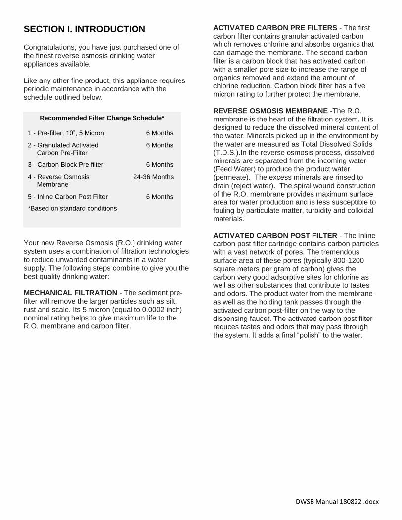
SECTION I. INTRODUCTION Congratulations, you have just purchased one of the finest reverse osmosis drinking water appliances available. Like any other fine product, this appliance requires periodic maintenance in accordance with the schedule outlined below.
Your new Reverse Osmosis (R.O.) drinking water system uses a combination of filtration technologies to reduce unwanted contaminants in a water supply. The following steps combine to give you the best quality drinking water: MECHANICAL FILTRATION - The sediment pre-filter will remove the larger particles such as silt, rust and scale. Its 5 micron (equal to 0.0002 inch) nominal rating helps to give maximum life to the R.O. membrane and carbon filter.
ACTIVATED CARBON PRE FILTERS - The first carbon filter contains granular activated carbon which removes chlorine and absorbs organics that can damage the membrane. The second carbon filter is a carbon block that has activated carbon with a smaller pore size to increase the range of organics removed and extend the amount of chlorine reduction. Carbon block filter has a five micron rating to further protect the membrane. REVERSE OSMOSIS MEMBRANE -The R.O. membrane is the heart of the filtration system. It is designed to reduce the dissolved mineral content of the water. Minerals picked up in the environment by the water are measured as Total Dissolved Solids (T.D.S.).In the reverse osmosis process, dissolved minerals are separated from the incoming water (Feed Water) to produce the product water (permeate). The excess minerals are rinsed to drain (reject water). The spiral wound construction of the R.O. membrane provides maximum surface area for water production and is less susceptible to fouling by particulate matter, turbidity and colloidal materials. ACTIVATED CARBON POST FILTER - The Inline carbon post filter cartridge contains carbon particles with a vast network of pores. The tremendous surface area of these pores (typically 800-1200 square meters per gram of carbon) gives the carbon very good adsorptive sites for chlorine as well as other substances that contribute to tastes and odors. The product water from the membrane as well as the holding tank passes through the activated carbon post-filter on the way to the dispensing faucet. The activated carbon post filter reduces tastes and odors that may pass through the system. It adds a final “polish” to the water.
Recommended Filter Change Schedule*
1 - Pre-filter, 10”, 5 Micron 6 Months
2 - Granulated Activated 6 Months Carbon Pre-Filter
3 - Carbon Block Pre-filter 6 Months
4 - Reverse Osmosis 24-36 Months Membrane
5 - Inline Carbon Post Filter 6 Months
*Based on standard conditions
4
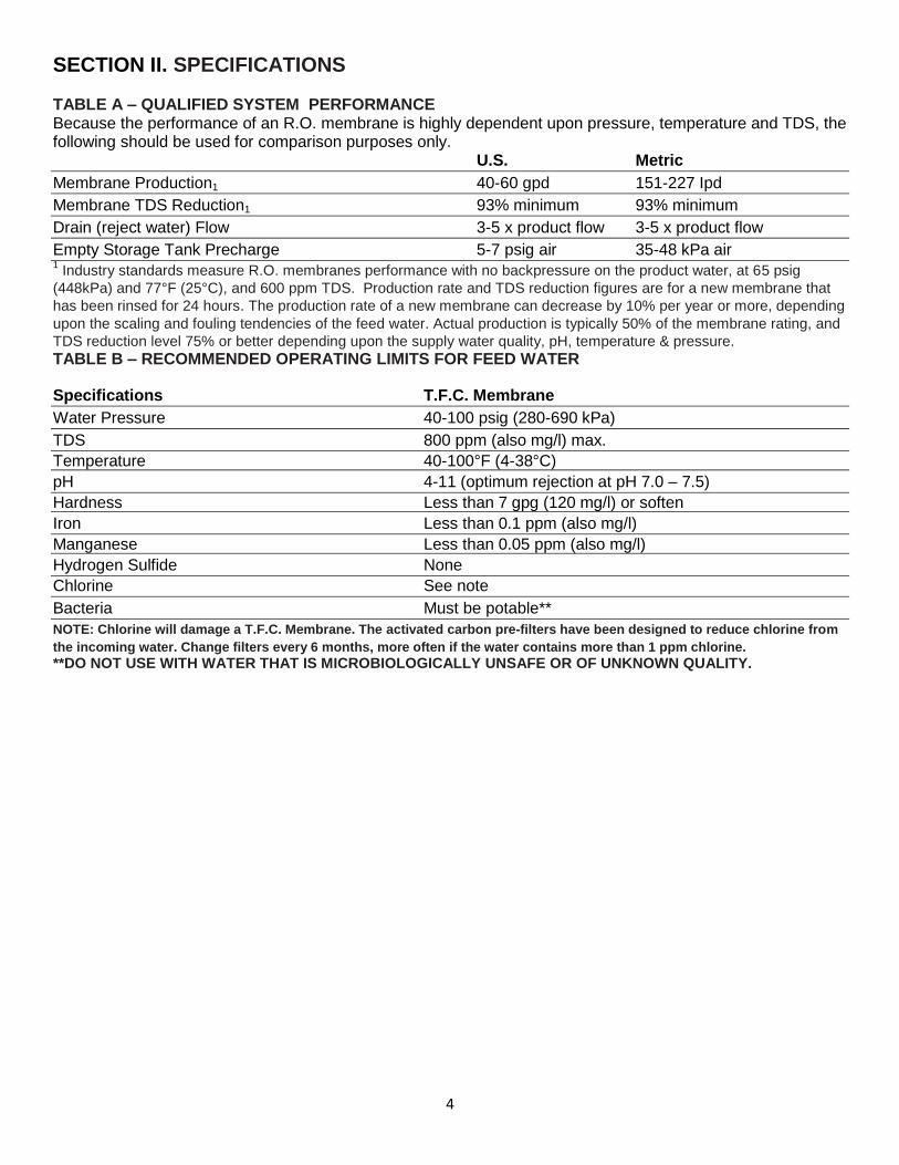
SECTION II. SPECIFICATIONS TABLE A – QUALIFIED SYSTEM PERFORMANCE Because the performance of an R.O. membrane is highly dependent upon pressure, temperature and TDS, the following should be used for comparison purposes only. U.S. Metric
Membrane Production1 40-60 gpd 151-227 Ipd
Membrane TDS Reduction1 93% minimum 93% minimum
Drain (reject water) Flow 3-5 x product flow 3-5 x product flow
Empty Storage Tank Precharge 5-7 psig air 35-48 kPa air 1 Industry standards measure R.O. membranes performance with no backpressure on the product water, at 65 psig
(448kPa) and 77°F (25°C), and 600 ppm TDS. Production rate and TDS reduction figures are for a new membrane that
has been rinsed for 24 hours. The production rate of a new membrane can decrease by 10% per year or more, depending
upon the scaling and fouling tendencies of the feed water. Actual production is typically 50% of the membrane rating, and
TDS reduction level 75% or better depending upon the supply water quality, pH, temperature & pressure.
TABLE B – RECOMMENDED OPERATING LIMITS FOR FEED WATER
Specifications T.F.C. Membrane
Water Pressure 40-100 psig (280-690 kPa)
TDS 800 ppm (also mg/l) max.
Temperature 40-100°F (4-38°C)
pH 4-11 (optimum rejection at pH 7.0 – 7.5)
Hardness Less than 7 gpg (120 mg/l) or soften
Iron Less than 0.1 ppm (also mg/l)
Manganese Less than 0.05 ppm (also mg/l)
Hydrogen Sulfide None
Chlorine See note
Bacteria Must be potable**
NOTE: Chlorine will damage a T.F.C. Membrane. The activated carbon pre-filters have been designed to reduce chlorine from
the incoming water. Change filters every 6 months, more often if the water contains more than 1 ppm chlorine.
**DO NOT USE WITH WATER THAT IS MICROBIOLOGICALLY UNSAFE OR OF UNKNOWN QUALITY.
5
SECTION III: PREPARATION A. Major System Components The following components comprise the R.O. drink-ing water system: 1) A reverse osmosis assembly consisting of the
aluminum bracket, filter housings, automatic shut-off, membrane module and an in-line carbon filter. Approx. 18”H x 15”W x 7”D
2) A drinking water storage tank. Approximate
dimensions (with base and ball valve): 16”H x 11” Diameter. 3. A faucet kit. 4. A plastic tubing kit with self-piercing saddle valve
and drain clamp. 5. Other items necessary for installation may
include wood screws or machine screws for mounting the R.O. assembly concrete anchors may be required for hanging on basement wall, additional tubing or tube connectors, and plastic wire ties for organizing tubing.
B. Tools Recommended for Installation
The following tools will cover most of the installation sites encountered:
3/8" variable speed electric drill.
Extension work light with outlet.
Safety Glasses.
1-1/4" porcelain hole cutter kit.
1-1/4" Greenlee hole punch and 1/8" and 1/2"metal drill bits for pilot hole.
Center punch and hammer.
1-1/4" wood bit.
Assorted wood and metal drill bits including 7/32" metal drill bit.
Phillips head and flat blade screwdrivers.
1/2", 9/16" and 5/8" open end wrench.
10" Crescent wrench with jaws taped to hold faucet.
Teflon tape.
Wide masking tape or duct tape.
Plastic tubing cutter.
Extra plastic tubing.
Low range air pressure gauge.
Bicycle hand air pump.
Small bottle of liquid chlorine bleach.
C. Determine System Location The R.O. system can be located under a sink or in a basement depending on space availability and the customer’s preference. If a basement installation is selected, additional tubing, hardware and fittings may be needed and a hole will have to be made from inside the cabinet, through the floor, to the basement. Never install in an area of the home where temperature is freezing as damage to the system will result. Considerations for an ice maker or other remote hook up should be determined, including routing and any additional tools, fittings, and tubing that may be required. CAUTION: If the system is installed where a leak may result in serious damage, a leak stop valve must be installed. (part number: RO-LSV)
1) Faucet - The faucet should be placed near the sink where drinking water is normally obtained. Convenience of use (filling of water pitchers and glasses), and an open area beneath the faucet under the sink for attaching product tubing are considerations. A 2" diameter flat surface is required above and below the mounting site. The thickness of the mounting surface should not exceed 1-1/4".Watch for strengthening webbing on the underside of cast iron sinks.
2) Drinking Water Storage Tank - The storage tank may be placed anywhere within 10 feet of the faucet. Under the sink or in an adjacent cabinet are best choices. If a longer run of tubing is required, the tubing should be 1/2" diameter O.D. size to pre-vent a high pressure drop. Remember, these tanks can weigh up to 30 pounds when full of water, a firm, and level area is required.
3) R.O Assembly - The R.O. assembly may be mounted anywhere under the sink area or a cabinet. Mounting in the basement is also an option, one possible location is near the laundry /utility sink where cold potable water and drain access is handy. The mounting location should allow adequate clearance and accessibility for cartridge changes.
6
4) Feed Water Connection - The self-piercing feed water shut off valve should be located as close to the R.O. assembly as possible. USE A POTABLE COLD WATER SUPPLY ONLY. Softened water is preferred as it will extend the life of the R.O. membrane.
5) Drain Connection - The drain saddle assembly is designed to fit around a standard 1-1/2" OD drain pipe. The drain saddle should always be installed above (before) the trap and on the vertical or horizontal tail piece. Never install the drain saddle close to the outlet of a garbage disposal or plugging of the RO drain line may occur. If discharging into an utility sink or standpipe, an air gap of greater than 1" above the flood rim must be provided. Do NOT connect the system drain line to the dishwasher drain or near the garbage disposal.
6) Leak Stop Valve – RO systems inherently have many connections which could leak. It is absolutely necessary to install the included Leak Stop Valve very close to and/or under the RO assembly. It must be fastened to the floor or cabinet base with screws or double-sided tape. The feed water supply must pass through the Leak Stop Valve. Should a leak occur and the underside of the Leak Stop Valve gets moist, the feed water will be terminated. Once activated, the Leak Stop Valve can be reset one time.
D. Prepare the Area for Installation To save time it is often advised to call the customer and request they clear under the sink prior to arrival. Otherwise, remove supplies from under the sink and stack them neatly away from the working area. Arrange a light for the work area, if necessary. If a basement installation is called for, determine where components will be located and how they will be mounted. Special mounting brackets and hardware may be necessary to secure the system to a wall or ceiling joists. Inspect cold water supply line and drain to determine if any special fittings, in addition to what is included in the kit, are required.
E. Prepare the Appliance for Installation Open shipping carton and remove components. Check that all installation parts are present which includes the R. O. assembly, storage tank, faucet, installation hardware, and tubing. Check that the air supply in the empty tank is approximately 7 psi. Adjust if necessary.
7
SECTION IV. INSTALLATION STEPS All plumbing should be done in accordance with state and local plumbing codes. NOTE: Some codes may require installation by a licensed plumber; check with the local plumbing authority prior to installation. In restricted under-sink areas, it may be easier to install the faucet first. Allow adequate tubing lengths for any final component position.
A. Install the Faucet See Figure 1 for Faucet Installation Diagram The customer should be consulted before determining faucet location. The faucet should be positioned so that it empties into the sink and the spout swivels freely for convenience. If the sink already has a hole provided that can accommodate the RO faucet, then no drilling is required and you can proceed to the section on mounting the faucet. 1. Make the Faucet Mounting Hole IMPORTANT: It is mandatory that safety glasses be worn during sink hole drilling operations to prevent eye injury. Before starting the hole making operation, always check below the sink so that nothing interferes with mounting the faucet such as reinforcing ribs, support brackets or cabinet construction. STAINLESS STEEL SINK: Recommended tools:
Center punch
Variable speed drill and high speed drill bits.
Greenlee chassis punch 7/8” hole size (alternate 9/16” size may be used for non air gap faucet)
Protective gloves Procedure:
a) Center punch a small indent at the desired faucet location.
b) Slowly drill the required pilot hole for the chassis punch.
c) Set up the chassis punch per instructions and tighten nut to cut the desired hole size.
d) Clean up sharp edges with a file if necessary.
PORCELAIN/ENAMEL/CERAMIC ON SHEET METAL OR CAST IRON BASE: Recommended tools:
Variable speed drill
Relton porcelain cutter tool set 7/8" size (alternate 9/16: size may be used for non-air gap faucet)
Plumber’s putty It is important to understand what is involved in this procedure. First, the glassy layer of porcelain must be penetrated through to the base metal. Second, a center disc of porcelain must be removed while protecting the surrounding porcelain against chip ping or fracturing. Third, the base metal must be drilled through to complete the hole. Procedure:
a) Mark the center for the 7/8” hole b) Form shallow putty dam around hole area
and fill with enough water to lubricate carbide drill bit.
c) Carefully drill plot hole through porcelain/enamel and base metal using carbide type pilot drill. IMPORTANT: Always operate drill with light pressure at slow speed (300-400 rpm).
d) Insert pilot tip of spring-loaded porcelain cutter into pilot hole.
e) Drill porcelain/enamel using spring-loaded porcelain cutter, making certain a complete ring has been cut through the porcelain/enamel to the metal base.
f) Change to the metal cutter. With slow speed and light pressure, cut away the inner porcelain/enamel disc down to base metal. Make certain that the cutter does not touch outer rim of the cut porcelain/enamel. Continue with this bit to cut through metal until sink has been completely penetrated. IMPORTANT: When using a porcelain cutter it is critical to take precautions that it is always in a sharpened condition. Dull cutters are known to chip sinks.
8
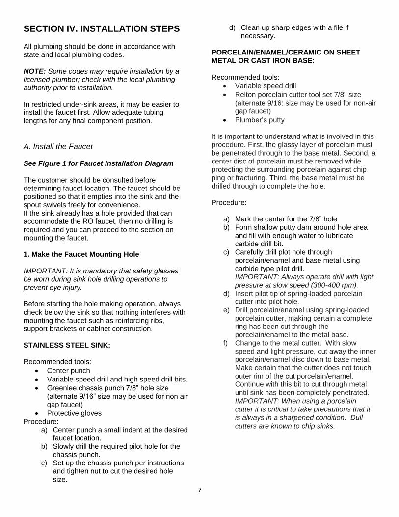
2. Mount the Faucet:
a) Familiarize yourself with all components shown in faucet diagram.
b) Remove the compression nut, plastic ferrule and hex nut from the threaded nipple and assemble the o-ring, chrome base plate and rubber washer onto the nipple. NOTE: Rubber washer may be replaced with bead of plumber’s putty for neater appearance.
c) Feed the threaded nipple through sink/counter mounting hole and orient the faucet as discussed with the customer.
d) From below sink/counter assemble the large metal washer, star washer and hex nut on threaded nipple and tighten by hand.
e) After rechecking faucet orientation, tighten hex nut (9/16" wrench or deep socket) until faucet feels secure.
f) From above the sink make any minor orientation corrections by turning the faucet with a padded adjustable wrench. Note: Flats on chrome faucet may be used for tightening with an adjustable wrench. Use care not to mar chrome finish.
g) Connect a length of standard 3/8" tubing to faucet. If using the standard compression fitting, ensure the plastic insert is in the end of the tubing. Feed the compression nut and plastic ferrule onto the tubing. Push the tubing and insert through the opening in the threaded nipple until it seats. Thread the compression nut onto the nipple and tighten securely. If using the quick connect faucet fitting (6FC4) instead, discard the
compression nut, plastic ferrule and tube insert. Thread the quick connect fitting securely onto the threaded nipple and firmly insert the 3/8" tubing into the quick connect fitting.
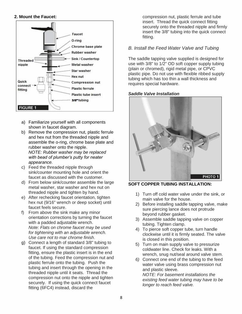
B. Install the Feed Water Valve and Tubing The saddle tapping valve supplied is designed for use with 3/8" to 1/2" OD soft copper supply tubing (plain or chromed), rigid metal pipe, or CPVC plastic pipe. Do not use with flexible ribbed supply tubing which has too thin a wall thickness and requires special hardware. Saddle Valve Installation SOFT COPPER TUBING INSTALLATION:
1) Turn off cold water valve under the sink, or main valve for the house.
2) Before installing saddle tapping valve, make sure piercing lance does not protrude beyond rubber gasket.
3) Assemble saddle tapping valve on copper tubing. Tighten clamp.
4) To pierce soft copper tube, turn handle clockwise until it is firmly seated. The valve is closed in this position.
5) Turn on main supply valve to pressurize coldwater line. Check for leaks. With a wrench, snug nut/seal around valve stem.
6) Connect one end of the tubing to the feed water valve using brass compression nut and plastic sleeve. NOTE: For basement installations the existing feed water tubing may have to be longer to reach feed valve.
9
RIGID METAL PIPE AND CPVC PLASTIC PIPE INSTALLATION:
1) Turn off cold water supply valve and drain the line to prevent spillage.
2) Drill 3/16" hole at the desired location. To pre-vent shock hazard, use a battery operated drill.
3) Before installing saddle tapping valve, make
sure piercing lance does not protrude beyond
rubber gasket.
4) Assemble saddle tapping valve on copper
tubing.
5) Turn saddle valve handle clockwise to close
valve. With a wrench tighten nut/seal around
valve stem.
6) When you wish to open valve and supply cold
water to the unit, turn valve handle counter
clock wise.
7) Connect one end of the tubing to the feed
water valve using brass compression nut and
plastic sleeve. NOTE: For basement installations the existing feed water tubing may have to be longer to reach feed valve.
C. Pre-fill and Sanitize the Storage Tank Pre-filling the tank is always recommended so there is pressure to check for leaks and several gallons of water to flush carbon post filter. Tanks are furnished with a special disinfectant and only require filling with water and 15 minutes of contact time to be completely sanitized. It is important to use a sanitizer when pre-filling tank so the solution can sanitize the tubing, fittings, and faucet at the time of installation and startup.
1) Insert free end of feed water tubing into the
fitting on the storage tank.
2) Open feed water valve and tank valve and
allow tank to fill (about 3 minutes). 3) Turn off feed water valve, tank valve, remove
tank from tubing and set tank aside (15 minutes minimum).
D. Install the Drain Connection IMPORTANT: Before starting this procedure, inspect the condition of the drain piping, especially in older homes where the traps and tailpieces can be deceptively thin and frail. If in poor condition, it is wise to inform the customer that the condition should be remedied.
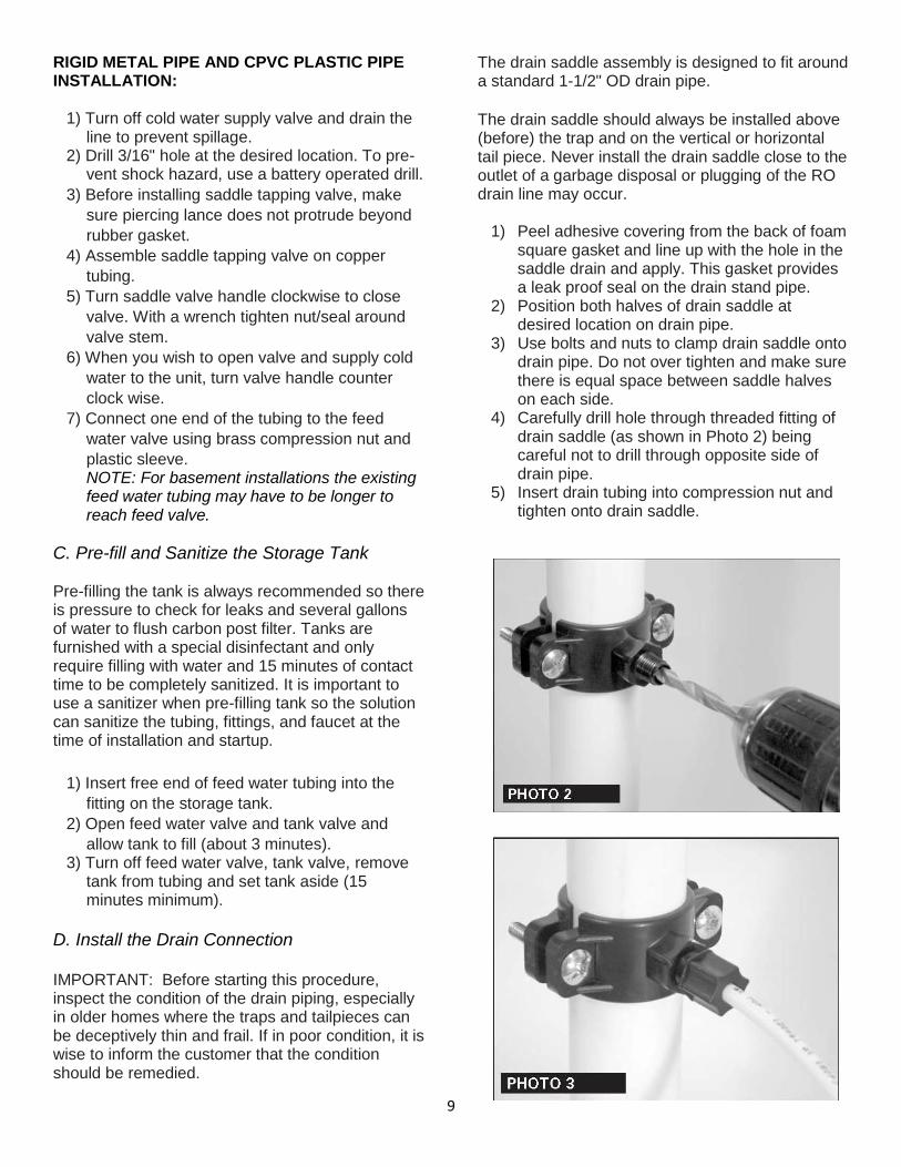
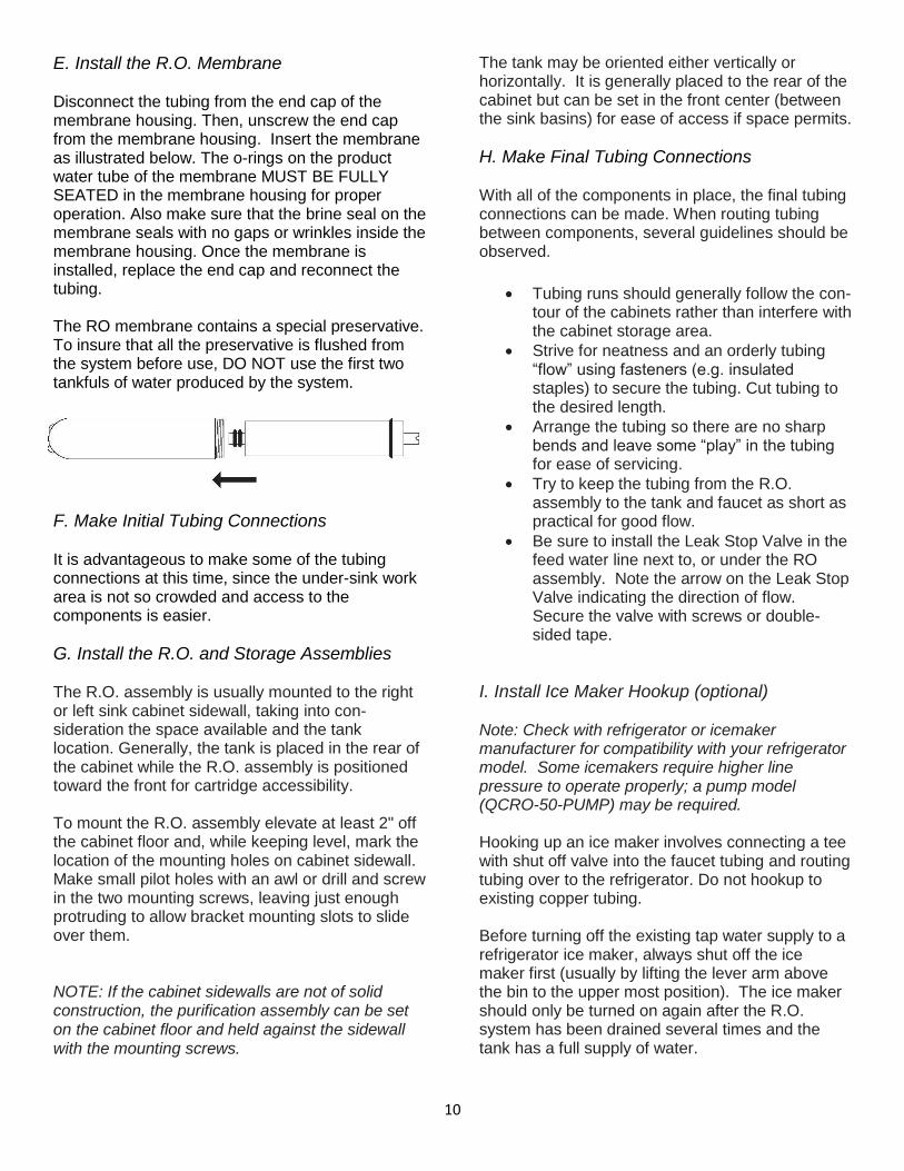
The drain saddle assembly is designed to fit around a standard 1-1/2" OD drain pipe. The drain saddle should always be installed above (before) the trap and on the vertical or horizontal tail piece. Never install the drain saddle close to the outlet of a garbage disposal or plugging of the RO drain line may occur.
1) Peel adhesive covering from the back of foam square gasket and line up with the hole in the saddle drain and apply. This gasket provides a leak proof seal on the drain stand pipe.
2) Position both halves of drain saddle at desired location on drain pipe.
3) Use bolts and nuts to clamp drain saddle onto drain pipe. Do not over tighten and make sure there is equal space between saddle halves on each side.
4) Carefully drill hole through threaded fitting of drain saddle (as shown in Photo 2) being careful not to drill through opposite side of drain pipe.
5) Insert drain tubing into compression nut and tighten onto drain saddle.
10
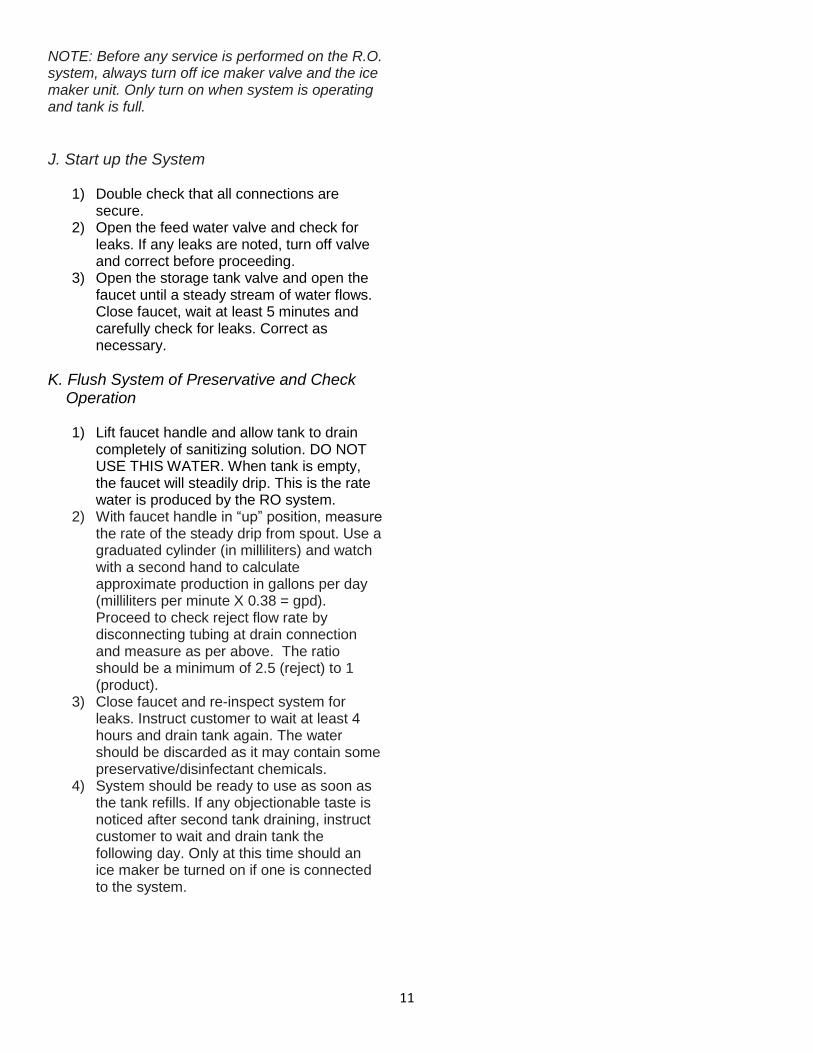
E. Install the R.O. Membrane Disconnect the tubing from the end cap of the membrane housing. Then, unscrew the end cap from the membrane housing. Insert the membrane as illustrated below. The o-rings on the product water tube of the membrane MUST BE FULLY SEATED in the membrane housing for proper operation. Also make sure that the brine seal on the membrane seals with no gaps or wrinkles inside the membrane housing. Once the membrane is installed, replace the end cap and reconnect the tubing. The RO membrane contains a special preservative. To insure that all the preservative is flushed from the system before use, DO NOT use the first two tankfuls of water produced by the system.
F. Make Initial Tubing Connections It is advantageous to make some of the tubing connections at this time, since the under-sink work area is not so crowded and access to the components is easier.
G. Install the R.O. and Storage Assemblies The R.O. assembly is usually mounted to the right or left sink cabinet sidewall, taking into con-sideration the space available and the tank location. Generally, the tank is placed in the rear of the cabinet while the R.O. assembly is positioned toward the front for cartridge accessibility. To mount the R.O. assembly elevate at least 2" off the cabinet floor and, while keeping level, mark the location of the mounting holes on cabinet sidewall. Make small pilot holes with an awl or drill and screw in the two mounting screws, leaving just enough protruding to allow bracket mounting slots to slide over them. NOTE: If the cabinet sidewalls are not of solid construction, the purification assembly can be set on the cabinet floor and held against the sidewall with the mounting screws.
The tank may be oriented either vertically or horizontally. It is generally placed to the rear of the cabinet but can be set in the front center (between the sink basins) for ease of access if space permits.
H. Make Final Tubing Connections With all of the components in place, the final tubing connections can be made. When routing tubing between components, several guidelines should be observed.
Tubing runs should generally follow the con-tour of the cabinets rather than interfere with the cabinet storage area.
Strive for neatness and an orderly tubing “flow” using fasteners (e.g. insulated staples) to secure the tubing. Cut tubing to the desired length.
Arrange the tubing so there are no sharp bends and leave some “play” in the tubing for ease of servicing.
Try to keep the tubing from the R.O. assembly to the tank and faucet as short as practical for good flow.
Be sure to install the Leak Stop Valve in the feed water line next to, or under the RO assembly. Note the arrow on the Leak Stop Valve indicating the direction of flow. Secure the valve with screws or double-sided tape.
I. Install Ice Maker Hookup (optional) Note: Check with refrigerator or icemaker manufacturer for compatibility with your refrigerator model. Some icemakers require higher line pressure to operate properly; a pump model (QCRO-50-PUMP) may be required. Hooking up an ice maker involves connecting a tee with shut off valve into the faucet tubing and routing tubing over to the refrigerator. Do not hookup to existing copper tubing. Before turning off the existing tap water supply to a refrigerator ice maker, always shut off the ice maker first (usually by lifting the lever arm above the bin to the upper most position). The ice maker should only be turned on again after the R.O. system has been drained several times and the tank has a full supply of water.
11
NOTE: Before any service is performed on the R.O. system, always turn off ice maker valve and the ice maker unit. Only turn on when system is operating and tank is full.
J. Start up the System
1) Double check that all connections are secure.
2) Open the feed water valve and check for leaks. If any leaks are noted, turn off valve and correct before proceeding.
3) Open the storage tank valve and open the faucet until a steady stream of water flows. Close faucet, wait at least 5 minutes and carefully check for leaks. Correct as necessary.
K. Flush System of Preservative and Check Operation
1) Lift faucet handle and allow tank to drain
completely of sanitizing solution. DO NOT USE THIS WATER. When tank is empty, the faucet will steadily drip. This is the rate water is produced by the RO system.
2) With faucet handle in “up” position, measure the rate of the steady drip from spout. Use a graduated cylinder (in milliliters) and watch with a second hand to calculate approximate production in gallons per day (milliliters per minute X 0.38 = gpd). Proceed to check reject flow rate by disconnecting tubing at drain connection and measure as per above. The ratio should be a minimum of 2.5 (reject) to 1 (product).
3) Close faucet and re-inspect system for leaks. Instruct customer to wait at least 4 hours and drain tank again. The water should be discarded as it may contain some preservative/disinfectant chemicals.
4) System should be ready to use as soon as the tank refills. If any objectionable taste is noticed after second tank draining, instruct customer to wait and drain tank the following day. Only at this time should an ice maker be turned on if one is connected to the system.
12
SECTION V. OPERATION & MAINTENANCE A. Normal Operation
1) It is normal for the Total Dissolved Solids (T.D.S.) of the water to be elevated during the first 5 gallons of operation; this is due to the sanitizing solution and the new post filter. After this water is rinsed to drain, the removal rate should stabilize at a value greater than 75%. Water pressure affects the production rate and quality.
2) R.O. systems produce drinking water at relatively slow rates; it can take up to 8 hours or more to fill the storage tank. Normal operation is to let the storage tank fill with water and then draw water as is needed. When the pressure in the storage tank falls to a given pressure (as the water is being used) the automatic shut-off valve (A.S.O. valve) will start water production and the system will refill the storage tank. When the storage tank is full and no water is being used, the A.S.O. valve will automatically shut off the feed water to conserve water.
The more water that is used (up to the capacity of the system) the better the R.O. system will function. After periods of non-use, such as a vacation, it is better to empty the holding tank and allow the system to produce fresh water for use. If the system is not used for 3-4 weeks or longer, it is a good idea to re-sanitize the system and to change the activated carbon and sediment filters.
B. Changing Filter & Sanitizing the system NOTE: THIS R.O. SYSTEM CONTAINS FILTERS WHICH MUST BE REPLACED AT REGULAR INTERVALS TO MAINTAIN PROPER PERFORMANCE. USE ONLY FACTORY APPROVED FILTERS. Please see Page 3 for the recommended interval for changing the filters. Local conditions may dictate more frequent changes.
Use a drip pan to catch any water that may spill when the filter housings are removed:
1) Close the saddle tapping valve by turning fully clock wise and open the dispensing faucet by lifting the handle. Allow the storage tank to empty.
2) Loosen and remove the Filter Housings and Discard the cartridges.
3) Disconnect the ¼” tubing from the cap of the membrane housing. Unscrew the membrane housing cap and remove the R.O. membrane. Place it in a clean, leak-proof container until it is reinstalled.
4) Wash the inside of the housings using a mild detergent and a soft cloth. Do not use abrasive cleaners or pads. Thoroughly rinse all soap from the housings before reassembly.
5) Steps to sanitize the system and replace the filter cartridge(s): NOTE: The system should be sanitized before installing the carbon post filter cartridge or the carbon pre-filter cartridges. a) Use a good quality unscented 5-1/4%
liquid household bleach. b) Add one cap full of bleach (this is 2 tsp.
or 10 ml) to the sediment filter housing. Install the sediment pre-filter only. Check the housing o-ring for proper position in its groove, replace sediment filter housing on R.O. assembly
c) Add one cap full of bleach to each of the carbon pre-filter housings. Carefully fill the housings with tap water and temporarily install the housings, without carbon filter cartridge.
d) Add one cap full of bleach to the R.O. membrane housing and replace the R.O. membrane housing cap and reconnect the ¼” tubing to the cap.
e) Disconnect the ¼” tubing from the end of the carbon post filter that runs to the storage tank and put 50 drops of bleach (1/2 tsp. or 3 ml) into the tubing and reconnect it to the end of the post filter.
f) The dispensing faucet should be open, slowly open the saddle tapping valve on the feed water line.
g) Let the water run from the faucet for 5 seconds, then shut off the faucet.
h) Let the system stand for 15 minutes. i) At the end of the 15 minutes, open the
dispensing faucet and allow it to run for 10 minutes.
13
j) Close the saddle tapping valve on the feed water line and allow the system to drain and relieve pressure.
k) Close the storage tank valve. l) Remove the carbon filter housings and
pour out the water. Disconnect and discard the old carbon post filter.
m) Remove any wrapping/packaging from carbon cartridges and install in housings. Check the o-ring to insure that it is positioned properly in its groove and replace housing(s) on RO unit. Connect the new carbon post filter.
n) Open the saddle tapping valve. When water begins dripping out of the dispensing faucet, in the following order, close the faucet and then open the storage tank valve.
o) Do not open the faucet for at least 8 hours.
p) Discard the first two full tanks of water produced, they will contain chlorine and carbon fines must be rinsed from the carbon post filter.
q) When the faucet is first opened, expect to see some air and carbon fines (very fine black powder) in the water. This is normal for the first tank or two of water after filter replacement.
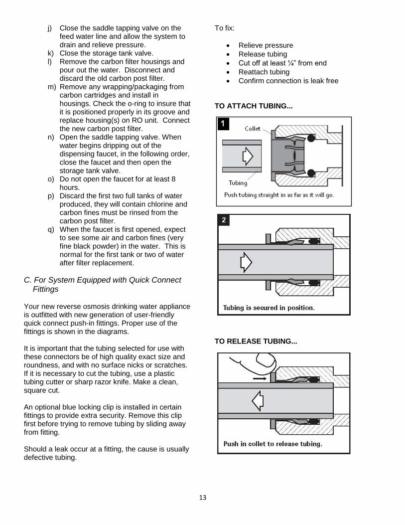
C. For System Equipped with Quick Connect Fittings
Your new reverse osmosis drinking water appliance is outfitted with new generation of user-friendly quick connect push-in fittings. Proper use of the fittings is shown in the diagrams. It is important that the tubing selected for use with these connectors be of high quality exact size and roundness, and with no surface nicks or scratches. If it is necessary to cut the tubing, use a plastic tubing cutter or sharp razor knife. Make a clean, square cut. An optional blue locking clip is installed in certain fittings to provide extra security. Remove this clip first before trying to remove tubing by sliding away from fitting. Should a leak occur at a fitting, the cause is usually defective tubing.
To fix:
Relieve pressure
Release tubing
Cut off at least ¼” from end
Reattach tubing
Confirm connection is leak free TO ATTACH TUBING...
TO RELEASE TUBING...
DWSB Manual 180822 .docx
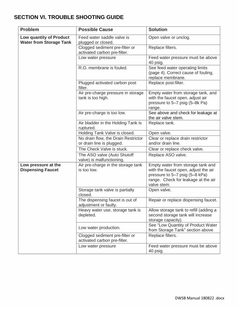
SECTION VI. TROUBLE SHOOTING GUIDE
Problem Possible Cause Solution
Low quantity of Product Water from Storage Tank
Feed water saddle valve is plugged or closed.
Open valve or unclog.
Clogged sediment pre-filter or activated carbon pre-filter.
Replace filters.
Low water pressure Feed water pressure must be above 40 psig.
R.O. membrane is fouled. See feed water operating limits (page 4). Correct cause of fouling, replace membrane.
Plugged activated carbon post filter.
Replace post-filter.
Air pre-charge pressure in storage tank is too high.
Empty water from storage tank, and with the faucet open, adjust air pressure to 5–7 psig (5–8k Pa) range.
Air pre-charge is too low. See above and check for leakage at the air valve stem.
Air bladder in the Holding Tank is ruptured.
Replace tank.
Holding Tank Valve is closed. Open valve.
No drain flow, the Drain Restrictor or drain line is plugged.
Clear or replace drain restrictor and/or drain line.
The Check Valve is stuck. Clear or replace check valve.
The ASO valve (Auto Shutoff valve) is malfunctioning.
Replace ASO valve.
Low pressure at the Dispensing Faucet
Air pre-charge in the storage tank is too low.
Empty water from storage tank and with the faucet open, adjust the air pressure to 5–7 psig (5–8 kPa) range. Check for leakage at the air valve stem.
Storage tank valve is partially closed.
Open valve.
The dispensing faucet is out of adjustment or faulty.
Repair or replace dispensing faucet.
Heavy water use, storage tank is depleted.
Allow storage tank to refill (adding a second storage tank will increase storage capacity).
Low water production. See “Low Quantity of Product Water from Storage Tank” section above
Clogged sediment pre-filter or activated carbon pre-filter.
Replace filters.
Low water pressure Feed water pressure must be above 40 psig.
15
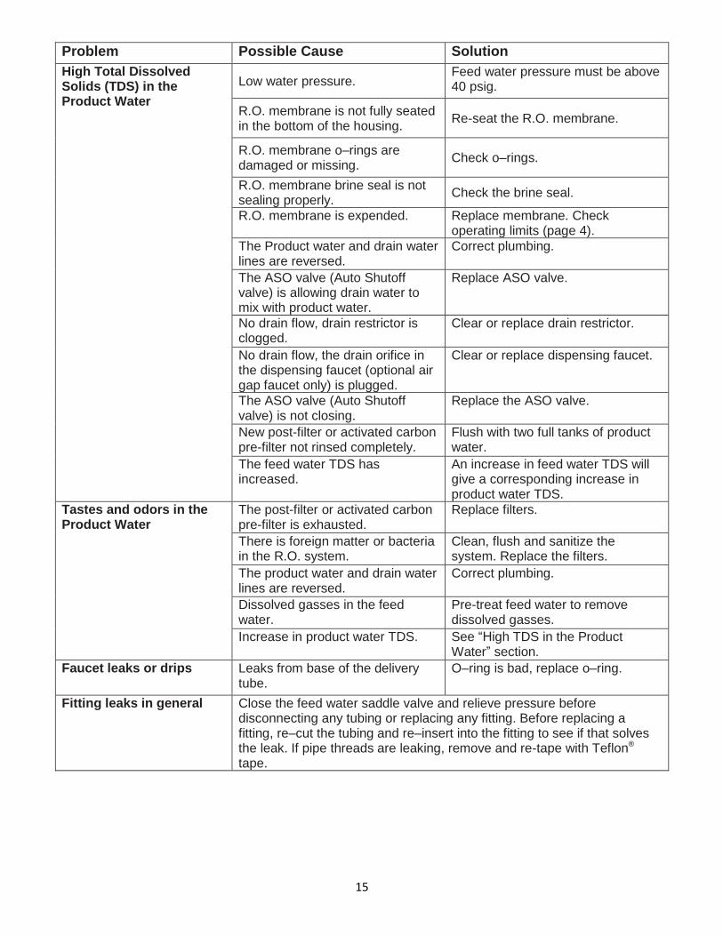
Problem Possible Cause Solution
High Total Dissolved Solids (TDS) in the Product Water
Low water pressure. Feed water pressure must be above 40 psig.
R.O. membrane is not fully seated in the bottom of the housing.
Re-seat the R.O. membrane.
R.O. membrane o–rings are damaged or missing.
Check o–rings.
R.O. membrane brine seal is not sealing properly.
Check the brine seal.
R.O. membrane is expended. Replace membrane. Check operating limits (page 4).
The Product water and drain water lines are reversed.
Correct plumbing.
The ASO valve (Auto Shutoff valve) is allowing drain water to mix with product water.
Replace ASO valve.
No drain flow, drain restrictor is clogged.
Clear or replace drain restrictor.
No drain flow, the drain orifice in the dispensing faucet (optional air gap faucet only) is plugged.
Clear or replace dispensing faucet.
The ASO valve (Auto Shutoff valve) is not closing.
Replace the ASO valve.
New post-filter or activated carbon pre-filter not rinsed completely.
Flush with two full tanks of product water.
The feed water TDS has increased.
An increase in feed water TDS will give a corresponding increase in product water TDS.
Tastes and odors in the Product Water
The post-filter or activated carbon pre-filter is exhausted.
Replace filters.
There is foreign matter or bacteria in the R.O. system.
Clean, flush and sanitize the system. Replace the filters.
The product water and drain water lines are reversed.
Correct plumbing.
Dissolved gasses in the feed water.
Pre-treat feed water to remove dissolved gasses.
Increase in product water TDS. See “High TDS in the Product Water” section.
Faucet leaks or drips Leaks from base of the delivery tube.
O–ring is bad, replace o–ring.
Fitting leaks in general Close the feed water saddle valve and relieve pressure before disconnecting any tubing or replacing any fitting. Before replacing a fitting, re–cut the tubing and re–insert into the fitting to see if that solves the leak. If pipe threads are leaking, remove and re-tape with Teflon® tape.
16
1
2
3a
4 5
6
7
8
9 10
DRAIN
SUPPLY
11 12 13
3
3
3
14
15
16 17 18
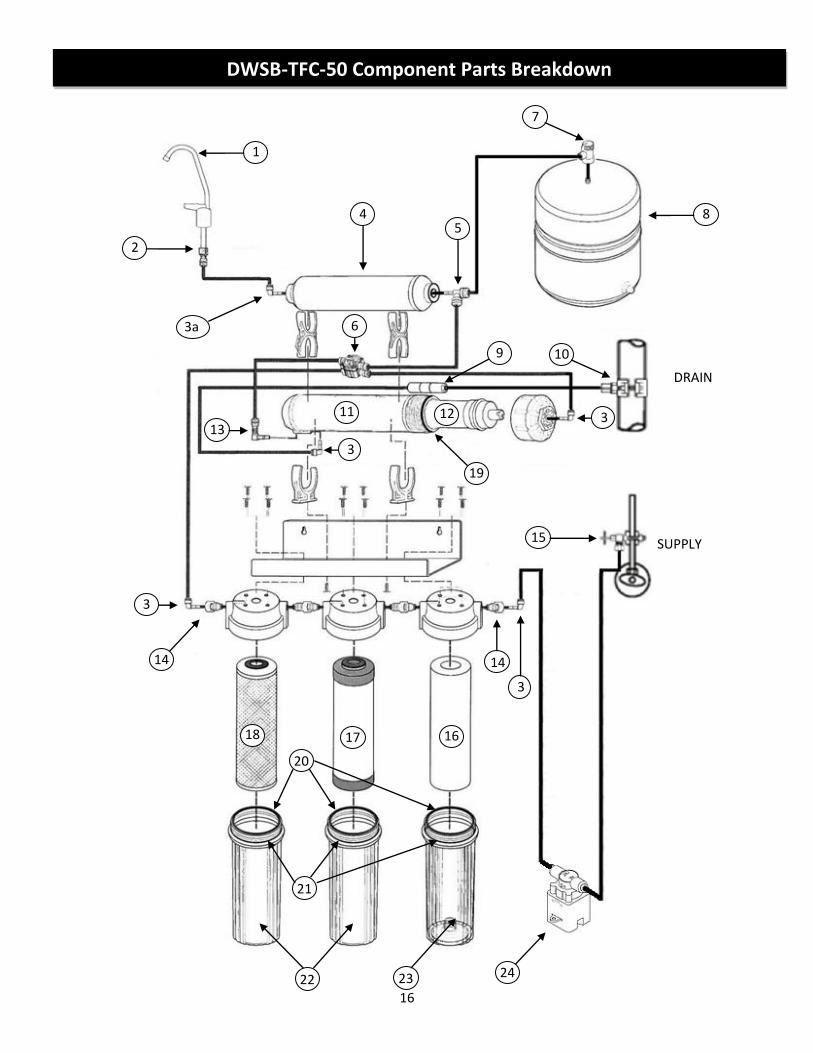
DWSB-TFC-50 Component Parts Breakdown
19
22 23
21
20
14
3
24
17
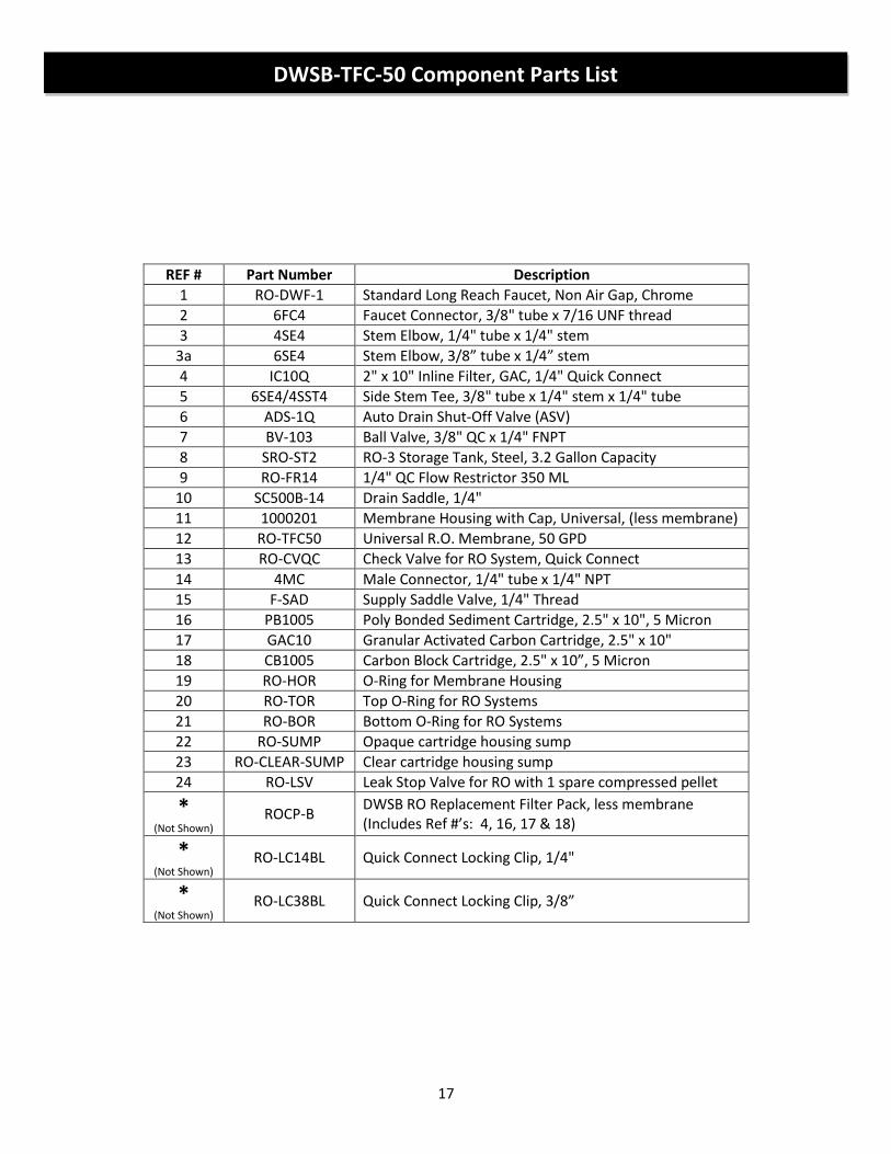
REF # Part Number Description
1 RO-DWF-1 Standard Long Reach Faucet, Non Air Gap, Chrome
2 6FC4 Faucet Connector, 3/8" tube x 7/16 UNF thread
3 4SE4 Stem Elbow, 1/4" tube x 1/4" stem
3a 6SE4 Stem Elbow, 3/8” tube x 1/4” stem
4 IC10Q 2" x 10" Inline Filter, GAC, 1/4" Quick Connect
5 6SE4/4SST4 Side Stem Tee, 3/8" tube x 1/4" stem x 1/4" tube
6 ADS-1Q Auto Drain Shut-Off Valve (ASV)
7 BV-103 Ball Valve, 3/8" QC x 1/4" FNPT
8 SRO-ST2 RO-3 Storage Tank, Steel, 3.2 Gallon Capacity
9 RO-FR14 1/4" QC Flow Restrictor 350 ML
10 SC500B-14 Drain Saddle, 1/4"
11 1000201 Membrane Housing with Cap, Universal, (less membrane)
12 RO-TFC50 Universal R.O. Membrane, 50 GPD
13 RO-CVQC Check Valve for RO System, Quick Connect
14 4MC Male Connector, 1/4" tube x 1/4" NPT
15 F-SAD Supply Saddle Valve, 1/4" Thread
16 PB1005 Poly Bonded Sediment Cartridge, 2.5" x 10", 5 Micron
17 GAC10 Granular Activated Carbon Cartridge, 2.5" x 10"
18 CB1005 Carbon Block Cartridge, 2.5" x 10”, 5 Micron
19 RO-HOR O-Ring for Membrane Housing
20 RO-TOR Top O-Ring for RO Systems
21 RO-BOR Bottom O-Ring for RO Systems
22 RO-SUMP Opaque cartridge housing sump
23 RO-CLEAR-SUMP Clear cartridge housing sump
24 RO-LSV Leak Stop Valve for RO with 1 spare compressed pellet
* (Not Shown)
ROCP-B DWSB RO Replacement Filter Pack, less membrane (Includes Ref #’s: 4, 16, 17 & 18)
* (Not Shown)
RO-LC14BL Quick Connect Locking Clip, 1/4"
* (Not Shown)
RO-LC38BL Quick Connect Locking Clip, 3/8”
DWSB-TFC-50 Component Parts List
18
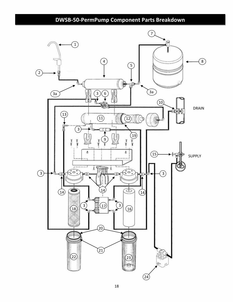
1
2
3a
4 5
6
7
8
10
DRAIN
SUPPLY
11 12
15
DWSB-50-PermPump Component Parts Breakdown
22 23
21
20
24
3a 3
9
3
13
14 14 14
3 3
19
18 16 17 3 3
19
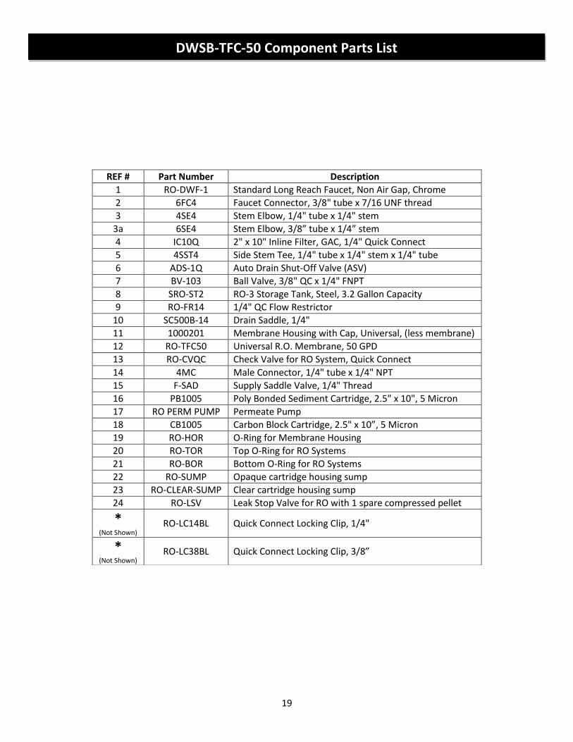
REF # Part Number Description
1 RO-DWF-1 Standard Long Reach Faucet, Non Air Gap, Chrome
2 6FC4 Faucet Connector, 3/8" tube x 7/16 UNF thread
3 4SE4 Stem Elbow, 1/4" tube x 1/4" stem
3a 6SE4 Stem Elbow, 3/8” tube x 1/4” stem
4 IC10Q 2" x 10" Inline Filter, GAC, 1/4" Quick Connect
5 4SST4 Side Stem Tee, 1/4" tube x 1/4" stem x 1/4" tube
6 ADS-1Q Auto Drain Shut-Off Valve (ASV)
7 BV-103 Ball Valve, 3/8" QC x 1/4" FNPT
8 SRO-ST2 RO-3 Storage Tank, Steel, 3.2 Gallon Capacity
9 RO-FR14 1/4" QC Flow Restrictor
10 SC500B-14 Drain Saddle, 1/4"
11 1000201 Membrane Housing with Cap, Universal, (less membrane)
12 RO-TFC50 Universal R.O. Membrane, 50 GPD
13 RO-CVQC Check Valve for RO System, Quick Connect
14 4MC Male Connector, 1/4" tube x 1/4" NPT
15 F-SAD Supply Saddle Valve, 1/4" Thread
16 PB1005 Poly Bonded Sediment Cartridge, 2.5" x 10", 5 Micron
17 RO PERM PUMP Permeate Pump
18 CB1005 Carbon Block Cartridge, 2.5" x 10”, 5 Micron
19 RO-HOR O-Ring for Membrane Housing
20 RO-TOR Top O-Ring for RO Systems
21 RO-BOR Bottom O-Ring for RO Systems
22 RO-SUMP Opaque cartridge housing sump
23 RO-CLEAR-SUMP Clear cartridge housing sump
24 RO-LSV Leak Stop Valve for RO with 1 spare compressed pellet
* (Not Shown)
RO-LC14BL Quick Connect Locking Clip, 1/4"
* (Not Shown)
RO-LC38BL Quick Connect Locking Clip, 3/8”
DWSB-TFC-50 Component Parts List

20
1) Pull the upper cover upward and separate it from the lower body. 2) Remove the expanded pellet from the retainer. 3) Replace the expanded pellet with the spare compressed pellet. 4) Seat the compressed pellet and retainer into the lower body. 5) Push the upper cover down until it snaps securely in place.
Leak Stop Valve – Compressed Pellet Replacement
21
R.O. DRINKING WATER SYSTEM LIMITED WARRANTY What Does This Warranty Cover? This warranty covers any defects in materials and workmanship of the R.O. Drinking Water System when installed and operated within recommended parameters, with the exceptions stated below. How Long Does The Coverage Last? The manufacturer will warrant its R.O. Drinking Water System, for a period of one year from the date of purchase. All implied warranties including merchantability and fitness for a particular purpose are limited to one year from the date of purchase for the R.O. Drinking Water System. Some states do not allow limitations on how long an implied warranty lasts, so the above limitations may not apply to you. What Will The Manufacturer Do? The manufacturer will repair or replace at its discretion any defective component. You must pay any labor charges. You must also pay for shipping or travel charges to return the defective part(s). What Does This Warranty Not Cover? This warranty does not cover the disposable sediment and carbon filters whose service life depends on feed water conditions. In addition, the membrane is only warranted if the required feed water conditions are met. The above warranty will also not apply to any part of the R.O. Drinking Water System that is damaged because of neglect, misuse, alterations, accident, misapplication, physical damage, or damage caused by fire, acts of God, freezing or hot waters or similar causes. Consequential and incidental damages are not recoverable under this warranty. Some states do not allow the exclusion or limitation of incidental or consequential damages, so the above limitation or exclusion may not apply to you. We recommend that you use only the manufacturer's replacement parts since improper parts or incorrectly performed maintenance or repair voids this warranty. How Do You Get Service? In order to be eligible for service under this warranty you must (a) contact your local dealer who supplied the unit. How Does State Law Apply? This warranty gives you specific legal rights and you may also have other rights which vary from state to state.


