Embed Size (px)
Citation preview
A.E.B. INDUSTRIALE s.r.l.Via Brodolini, 8 - 40056 Crespellano (Bo) - ITALIATel. + 39 051 969870 - Fax. + 39 051 969725Internet: www.dbtechnologies.comE-mail: [email protected]

Ita
lian
oIta
lian
oIta
lian
oM
an
ua
le d
’us
oM
an
ua
le d
’us
o
1
Ita
lian
oIta
lian
oIta
lian
oM
an
ua
le d
’us
oM
an
ua
le d
’us
o
2
Input Link
Ready
Limiter
Signal
Mute/Prot
Input
Link
ServiceDataUSB
Remote PresetActive
Link
Active
0dB
+4dB
Audio Balanced Input/Link
Input Control
RDNETSUB Phase/Delay
Input Sens
Status
7580
85
90
95100105
110
115
120
Xover Out
Xover Frequency selection 24dB/oct
00.5
1.0
1.5
2.02.5
3.0
3.5
4.0
Phase
mSec
DSP Up-grade
Hz
30
4.50°180°
Delay
ON
FF
O
FULL RANGE MAINS INPUT 100-240V~ 50-60Hz
3750W MAX
ACTIVE P.F.C.
Digital Vertical ArrayS
Made in Italy
Ita
lian
oIta
lian
oIta
lian
oM
an
ua
le d
’us
oM
an
ua
le d
’us
o
3
Ita
lian
oIta
lian
oIta
lian
oM
an
ua
le d
’us
oM
an
ua
le d
’us
o
4
Ita
lian
oIta
lian
oIta
lian
oM
an
ua
le d
’us
oM
an
ua
le d
’us
o
5
En
glis
hE
ng
lish
En
glis
hu
se
r m
an
ua
lu
se
r m
an
ua
l
6
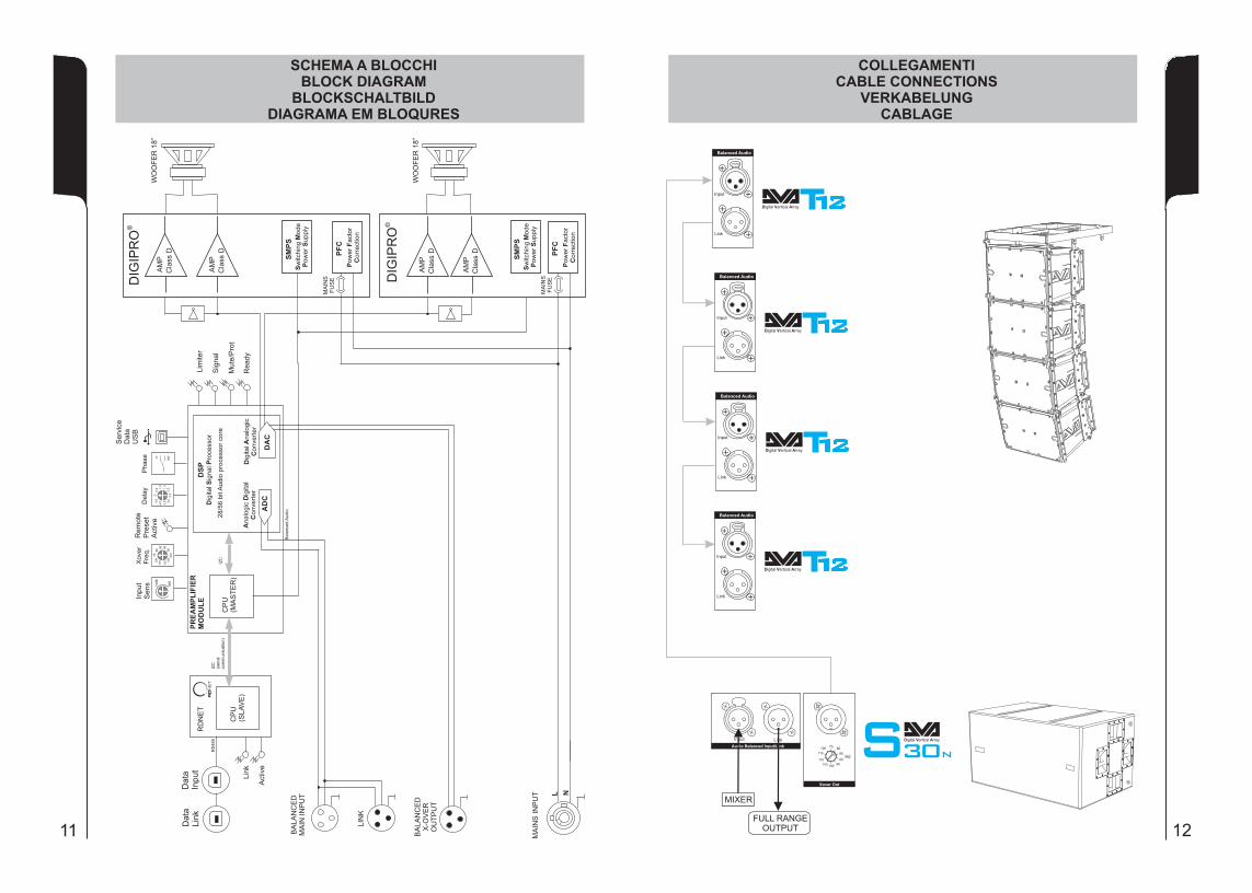
CONTROLS AND FUNCTIONS (Ref. Page 9)
"Balanced Audio" section
1) " INPUT” INPUT CONNECTORBalanced input at line level. It is able to accept “XLR” sockets.
2) "LINK” OUTPUT CONNECTORThe “XLR” connector connected in parallel with input (1) can be used to send the input audio signal to another amplified speaker.
"Status" section
3) “LIMITER” INDICATOR LIGHTThis indicator comes on red to indicate that the internal limiter circuit has tripped. This prevents amplifier distortion and protects the speakers against overloads.
Always avoid operating conditions where the system works for long periods of time with LED flashes or it is always ON
4) “SIGNAL” INDICATOR LIGHT
This indicator comes on green to indicate the presence of an input signal to a level higher than-20dBu.
5) “MUTE/PROT” INDICATOR LIGHTThis yellow indicator indicates amplifier status. In normal operating conditions, the LED is off; if it flashes or is always on, refer to the diagnostics table to check amplifier status.
6) “READY” INDICATOR LIGHTThis indicator comes on green to indicate that the main power voltage is correct. In normal operating conditions, the LED is on; if it flashes or is off, refer to the diagnostics table to check amplifier status.
"Input control " section
7) “INPUT SENS” INPUT SENSITIVITY CONTROLThis control regulates the sensitivity of the signal amplifier input. This control does not affect the “LINK” (2) output level.
"Xover Out " section
8) OUTPUT CONNECTOR Internal crossover audio balanced output, by XLR connector. The signal from this output can be sent to any other amplified speaker.The crossover frequency can be selected by means “Xover Frequency” switch (9).
9) "Xover Frequency selection 24dB/Oct” SELECTOR This selector permits selection of crossover frequency from 75Hz to 120Hz (step 5Hz) with a slope of 24dB/Oct.The frequency choice depends to the reproduction desired and from system configuration.
10) “Remote Preset Active” INDICATION LIGHTWhen the amplifier is remotely controlled via RDNET, this yellow indicator indicates the exclusion of the below commands:Volume (7)Phase (11)Xover Frequency selection (9)Delay (12)
7
En
glis
hE
ng
lish
En
glis
hu
se
r m
an
ua
lu
se
r m
an
ua
l
En
glis
hE
ng
lish
En
glis
hu
se
r m
an
ua
lu
se
r m
an
ua
l
8
!!
11)
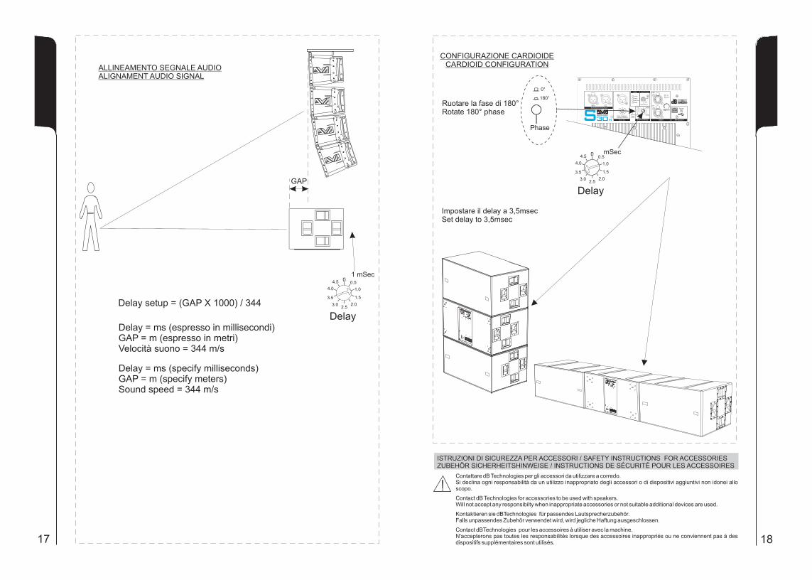
12) "DELAY” CONTROL This
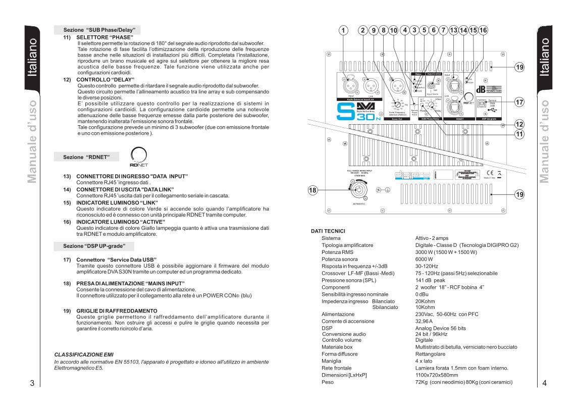
circuit allows sound-alignment between line array and sub by balancing the various positions. This control can also be used to create cardioid configuration systems. The cardioid configuration provides a remarkable attenuation of the low frequencies radiated by the rear side of the subs, without changing the direct radiated signal on the front side. This configuration needs at least 3 subwoofers (two with front radiation and one with rear radiation).
“RDNET " section
13) INPUT CONNECTOR "DATA INPUT” RJ45 connector 'data input.
14) OUTPUT CONNECTOR "DATA INPUT” RJ45 connector 'data output for cascading connections.
15) “LINK” INDICATION LIGHTThis green indicator turns on only when the amplifier has recognized and is connected with the main RDNET unit via the computer.
16) “ACTIVE” INDICATOR LIGHT This yellow indicator flashes when there is an active data transmission between RDNET and the amplifier module.
“DSP UP-grade " section
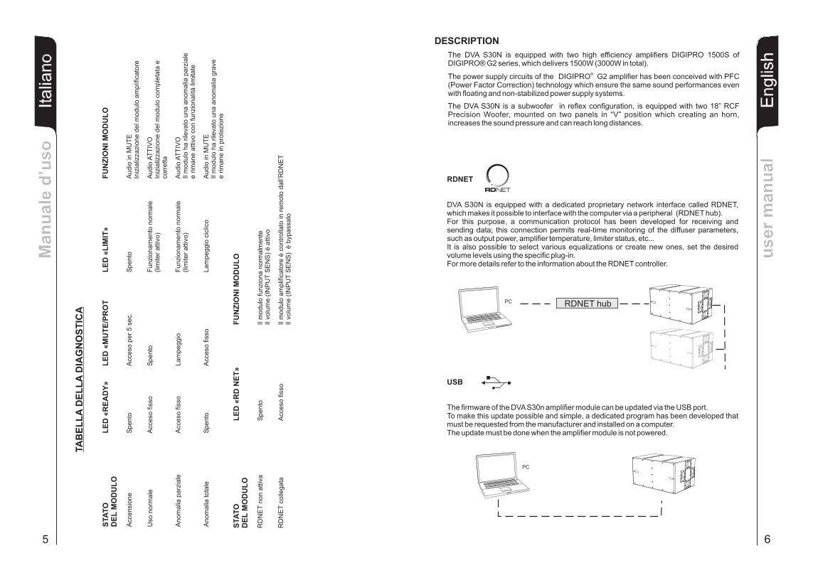
17) “Service Data USB” Connector Via this USB connector, it is possible to update the firmware of the DVA S30n amplifier module using the computer and a dedicated program.
18) "MAINS INPUT" POWER SOCKETFor connecting the power cable.The connector used for mains connection is a POWER CON® (blue)
“PHASE ” SWITCHThis switch permits 180° rotation of the audio signal reproduced by subwoofer.Rotation makes for easier optimization of low-frequency reproduction even in the most difficult installation situations. After completing installation, reproduce a track of music and adjust the switch to obtain the best low-frequency sound.This function it is used also for cardioid configuration.
This control allows to delay the sound signal reproduced by the subwoofer.
19) COOLING GRILLEThese grilles permit cooling the amplifier during operation. Do not block accesses and clean the grilles whenever necessary to ensure correct air circulation.

9
En
glis
hE
ng
lish
En
glis
hu
se
r m
an
ua
lu
se
r m
an
ua
l
En
glis
hE
ng
lish
En
glis
hu
se
r m
an
ua
lu
se
r m
an
ua
l
10
Input Link
Ready
Limiter
Signal
Mute/Prot
Input
Link
ServiceDataUSB
Remote PresetActive
Link
Active
0dB
+4dB
Audio Balanced Input/Link
Input Control
RDNETSUB Phase/Delay
Input Sens
Status
7580
85
90
95100105
110
115
120
Xover Out
Xover Frequency selection 24dB/oct
00.5
1.0
1.5
2.02.5
3.0
3.5
4.0
Phase
mSec
DSP Up-grade
Hz
30
4.50°180°
Delay
ON
FF
O
FULL RANGE MAINS INPUT 100-240V~ 50-60Hz
3750W MAX
ACTIVE P.F.C.
Digital Vertical ArrayS
Made in Italy
11 12
13 14
15 16
17 18