Embed Size (px)
Citation preview

Specification Data
CH28000
10/06
Precise Microflow Valveswith Compact Designand Flexible Capabilities
Masoneilan®
28000 SeriesVaripak® Control Valves
DV-195-28000 SD-f2.qxd 9/28/06 2:31 PM Page 1

CH28000 SD - 10/06Varipak® 28000 Series Control Valves 2
Table of Contents
Foreword
Designed specifically for low flow applications, the Masoneilan28000 Series Varipak provides excellent throttling control performance with a wide range of options and capabilities.Design optimization has also resulted in an extremely integratedand compact assembly. Key design features include:
Heavy Top-GuidingRugged valve plug support is provided along the entire strokelength using an integrated plug guide and seat ring.This ensures excellent plug stability and control even underhigh pressure drop conditions. Heavy guiding is critical for controlling vibration damage, providing dependable control andseating performance, and minimizing trim mechanical wear.
Application Flexibility Ten standard contoured trim designs are available providingflexible application using the same body platform. This helps toeliminate the effects of valve oversizing and improves controlloop performance resulting in higher process efficiency.
Adjustable CvIn addition to multiple standard trim sets, the Varipak is alsoavailable with an adjustable Cv option. This feature allowsusers to easily increase or decrease the Cv setting in order toaccommodate changing operating conditions. Adjustment isachieved by simply setting a knob within the actuator assembly(see page 4 for details).
Compact AssemblyMaximum space savings is provided by the Varipak assemblythrough modular design and force amplification actuator tech-nology. The actuator also includes a low profile top-mountedhandwheel option.
Anti-Cavitation TrimVaripak is also available with an effective high pressure liquidletdown anti-cavitation trim solution - the Varilog® trim. This
Numbering System . . . . . . . . . . . . . . . . . . . . . . . . .3Micro-Flow Control Innovation . . . . . . . . . . . . . . . . .4General Data . . . . . . . . . . . . . . . . . . . . . . . . . . . . . .5Materials of Construction . . . . . . . . . . . . . . . . . . . . .6Standard Flangeless Varipak . . . . . . . . . . . . . . . . . .8Standard Flanged Varipak . . . . . . . . . . . . . . . . . . . .9Varilog® Anti-Cavitation Varipak . . . . . . . . . . . . . . .10High Pressure Varipak . . . . . . . . . . . . . . . . . . . . . .11Bellows Seal Varipak . . . . . . . . . . . . . . . . . . . . . . .12Cryogenic Varipak . . . . . . . . . . . . . . . . . . . . . . . . .13Accessories and Options . . . . . . . . . . . . . . . . . . . .14Standard Actuator Options . . . . . . . . . . . . . . . . . .15
unique design includes a multi-stage axial flow plug and liner,which provides dirt tolerant operation and high wear resistance.
Design FlexibilityOther standard configurations include a High Pressure ANSIClass 2500 design, a zero emissions Bellows Seal design, and a design for cryogenic applications. The Varipak is alsoavailable with an angle body design to accommodate existing piping configurations.
Ease of MaintenanceVaripak's simple top-entry body construction includes an inte-grated body and bonnet design, which allows for easy accessand removal of the quick change trim. The integral liner andseat ring also reduces components and simplifies assemblyand disassembly. Modularity of the actuator design furtherenhances maintainability of this unique valve assembly.
Figure 1: Varipak Family
DV-195-28000 SD-f2.qxd 9/28/06 2:31 PM Page 2

CH28000 SD - 10/06Varipak® 28000 Series Control Valves 3
Numbering System
2nd 2nd8
5th4th3rd1st2
1st2
Suffix
Particulars contained in this publication are for general information only and Masoneilan reserves the right to modify thecontents without prior notice. No warranty either expressed or implied is either given or intended.
Actuatortype
27 Air-to-Close28 Air-to-Open
Bodyseries
28
Actuator mountingposition
0 Undefined1 (*) (**)2 (**)34
* Standard actuator mounting arrangement
** Flanged valvemounting positionsFace-to-face =102 mm (4.02")
Trim MaximumN° Cv
0 3.81 2.32 1.23 0.64 0.255 0.106 0.0507 0.0258 0.0109 0.004
ConstructionOption
StandardA Angle
BS Bellows sealEB CryogenicHP High pressureMS Anti-cavitationSP Special
Figure 2: Actuator Mounting Positions
AdjustableCv
0 Undefined1 Without2 With
DV-195-28000 SD-f2.qxd 9/28/06 2:31 PM Page 3

CH28000 SD - 10/06Varipak® 28000 Series Control Valves 4
Micro-Flow Control Innovation
Optimized Cv CharacteristicsVariPak is far superior to conventional microflow valves in that it provides the user with a very wide range of nominal Cv ranges from 0.0016 to 3.8, using only eight plugs and five seats.
Figure 3: Flow Coefficient Adjustment
Precise CV Calibration and Selection - CV and FL
Valve SizesTrimNo.
Flow Coefficient Cv
With Adjustable Cv FunctionWithout
Adjustable Cv Function
.5"(15mm)
.75"(20mm)
1"(25mm)
MinRisk-Free
Max
• • • 9 0.0016 0.0020 0.0024 0.0028 0.0032 0.0036 0.0040 0.0040
• • • 8 0.004 0.005 0.006 0.007 0.008 0.009 0.010 0.010
• • • 7 0.010 0.013 0.016 0.019 0.021 0.023 0.025 0.025
• • • 6 0.020 0.025 0.030 0.035 0.040 0.045 0.050 0.050
• • • 5 0.04 0.05 0.06 0.07 0.08 0.09 0.10 0.10
• • • 4 0.10 0.13 0.16 0.19 0.21 0.23 0.25 0.25
• • • 3 0.25 0.30 0.35 0.40 0.45 0.50 0.55 0.60 0.60
• • • 2 0.5 0.6 0.7 0.8 0.9 1.0 1.1 1.2 1.2
• • • 1 0.9 1.1 1.3 1.5 1.7 1.9 2.1 2.3 2.3
• • 0 1.5 1.9 2.3 2.6 2.9 3.2 3.5 3.8 3.8
Critical Flow
Factor FL
0.85
0.85
0.85
0.85
0.85
0.90
0.90
0.92
0.92
0.92
(1) Flangeless, flanged or threaded connections.(2) Flangeless connections.(3) The "Risk-free" setting allows for easy valve capacity adjustments in the field to meet changing service conditions.
(2) (1)
(3)
DV-195-28000 SD-f2.qxd 9/28/06 2:31 PM Page 4
CH28000 SD - 10/06Varipak® 28000 Series Control Valves 5
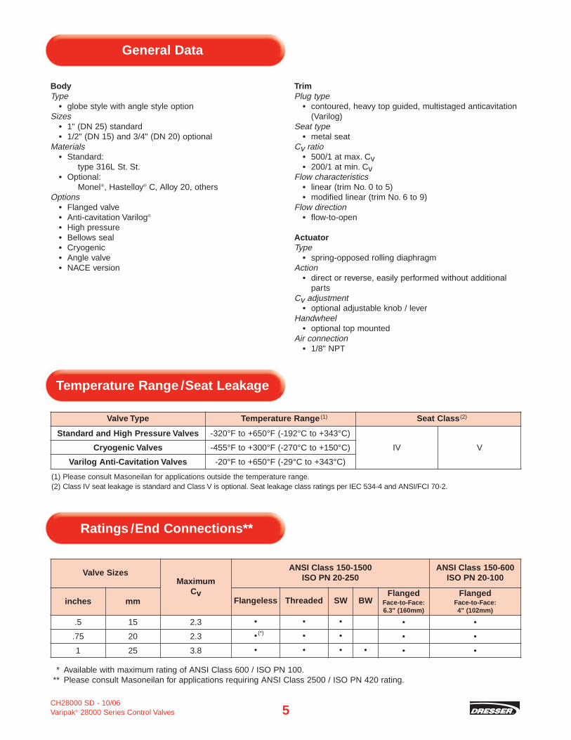
General Data
Temperature Range /Seat Leakage
Ratings /End Connections**
BodyType
• globe style with angle style optionSizes
• 1" (DN 25) standard• 1/2" (DN 15) and 3/4" (DN 20) optional
Materials• Standard:
type 316L St. St.• Optional:
Monel®, Hastelloy® C, Alloy 20, othersOptions
• Flanged valve• Anti-cavitation Varilog®
• High pressure• Bellows seal• Cryogenic• Angle valve• NACE version
TrimPlug type
• contoured, heavy top guided, multistaged anticavitation(Varilog)
Seat type• metal seat
Cv ratio • 500/1 at max. Cv• 200/1 at min. Cv
Flow characteristics• linear (trim No. 0 to 5)• modified linear (trim No. 6 to 9)
Flow direction• flow-to-open
ActuatorType
• spring-opposed rolling diaphragmAction
• direct or reverse, easily performed without additionalparts
Cv adjustment• optional adjustable knob / lever
Handwheel • optional top mounted
Air connection• 1/8" NPT
Valve SizesMaximum
Cv
ANSI Class 150-1500ISO PN 20-250
ANSI Class 150-600ISO PN 20-100
inches mm Flangeless Threaded SW BWFlanged
Face-to-Face:6.3" (160mm)
Flanged Face-to-Face:4" (102mm)
.5 15 2.3 • • • • •
.75 20 2.3 • • • • •
1 25 3.8 • • • • • •
Valve Type Temperature Range Seat Class
Standard and High Pressure Valves -320°F to +650°F (-192°C to +343°C)
IV VCryogenic Valves -455°F to +300°F (-270°C to +150°C)
Varilog Anti-Cavitation Valves -20°F to +650°F (-29°C to +343°C)
(1) Please consult Masoneilan for applications outside the temperature range.(2) Class IV seat leakage is standard and Class V is optional. Seat leakage class ratings per IEC 534-4 and ANSI/FCI 70-2.
* Available with maximum rating of ANSI Class 600 / ISO PN 100.** Please consult Masoneilan for applications requiring ANSI Class 2500 / ISO PN 420 rating.
(2)(1)
(*)
DV-195-28000 SD-f2.qxd 9/28/06 2:31 PM Page 5

15
14
13
11
9
10
7
6
8
3
2
1
12
5
4
Figure 4: Cut-away View
CH28000 SD - 10/06Varipak® 28000 Series Control Valves 6
Materials
DV-195-28000 SD-f2.qxd 9/28/06 2:31 PM Page 6

Ref.No.
Temperature Range-320°F +450°F +650°F-196°C +232°C +343°C
-20°F +450°F-29°C +232°C
Description Standard Materials (Optional Materials) NACE Materials
1 Body
316L St. St. ASTM A182 Gr. F 316L (forging)22 HRC Max.
316L St. St. ASTM A351 Gr. CF3M (casting)
Optional: Monel ®, Hastelloy ® C, Alloy 20
2 Seat
17-4 PH St. St. ASTM A564 Gr. 630 Condition H900(Max Cv >_ 0.10, trims No. 0 to 5) MONEL K 500 35 HRC Max.
Solid Stellite® No. 6 (Max Cv <_ 0.05, trims No. 6 to 9) 35 HRC Max.
Optional: 440C St. St., Monel ®, Hastelloy ® C, Alloy 20
3Plug and Stem S/A
Plug Solid Stellite® No. 6 (Max Cv >_ 0.10, trims No. 0 to 5)
22 HRC Max.Stem 316 St. St. (Max Cv >_ 0.10, trims No. 0 to 5)
One Piece Solid Stellite® No. 12 (Max Cv <_ 0.05, trims No. 6 to 9)
Optional: 440C St. St., Monel ®, Hastelloy ® C, Alloy 20
4 Seat Ring Gasket Grafoil® with 316 St. St. inserts PTFE Fiberglass Reinforced
5 Seat Ring Retainer 17-4 PH St. St. ASTM A564 Gr. 630 Condition H1075 MONEL K 500 35 HRC Max.
6 Packing
Kevlar ® PTFE (standard up toASME Class 1500)
Kevlar ® PTFE (standard up toASME Class 1500)
Lattyflon® (with optional Viton® O-rings) Lattyflon® (with optional Viton® O-rings)
7 Packing Follower 303 St. St. ASTM A582 TY 303 ASTM A479 TY 304 22 HRC Max.
8 Packing Spacer 316 St. St. ASTM A479 TY 316 22 HRC Max.
9 Packing Flange 304 St. St. AISI 304 ASTM A743 Gr. CF8 22 HRC Max.
10 Packing Flange Studs 304 St. St. ASTM A193 Gr. B8
304 St. St. ASTM A193 Gr. B8(Class III)
304 St. St. ASTM A193 Gr. B8 (Class I or II) 22 HRC Max.
11 Packing Flange Nuts 304 St. St. ASTM A193 Gr. 8
304 St. St. ASTM A194 Gr. 8 (Class III)
304 St. St. ASTM A194 Gr. 8A (Class I or II) 22 HRC Max.
12 Safety Pin 316 St. St. ASTM A479 TY 316 22 HRC Max.
13 Cv Adjustment Knob Stainless Steel Stainless Steel
14 Actuator CoverPolycarbonate Polycarbonate
Optional: Stainless Steel Optional: Stainless Steel
15 Handwheel (optional) Lexan® + Austenitic St. St. Lexan® + Austenitic St. St.
CH28000 SD - 10/06Varipak® 28000 Series Control Valves 7
Materials
∇ ∇ ∇∇
Materials* (Standard and NACE Construction) ((11))
* Materials noted throughout text are for reference only. Masoneilan reserves the right to supply trade name material or equivalent.
Material not applicable
Notes:
(1) Materials and processes in accordance with the requirements of NACE specification MR0103.Applications requiring compliance to MR0175, 2003 Rev. or ISO 15156 would require engineering review.
(2) Materials designated for these parts conform to NACE Class III bolting requirements.(3) Materials designated for these parts conform to NACE Class I or Class II bolting requirements.(4) Consult Masoneilan for NACE Applications above ANSI Class 600 rating.
DV-195-28000 SD-f2.qxd 9/28/06 2:31 PM Page 7

CH28000 SD - 10/06Varipak® 28000 Series Control Valves 8
Standard Flangeless Varipak - 28000 Series
Rated CV Range /Weight
Dimensions - inches (mm)
The standard flangeless Varipak valve is widely used in all industries. This can be attributed to the overall compactness and simplicity of the flangelessconstruction, and the wide application range of the stainless steel body design.
• Numbering system: see page 3.• General data: see page 5.• Materials: standard construction, see page 7.• Accessories and options: see page 14.
Provide a removal clearance of 5.5 inches (140 mm)
Standard Varipak (Stainless Steel) Bar Stock Body (For Non-Castable Material)
Handwheel (optional)
1⁄2" NPT3⁄4" NPT Optional1" NPT
2 holes tapped5⁄16" - 18 UNC
depth 11 (7⁄16")
)
4.13(105)
10.24(260)
1.30(33)
4.02(102) 8.56
(217.5)
11.10(282)
12.80(325)
1.10(28)
1.77(45)
Body / Actuator Assembly Weight Rated CV Range
15.4 lbs (7 kg) 3.8 to 0.0040 (trim No. 0 to 9)
Figure 5: Standard Flangeless Varipak
DV-195-28000 SD-f2.qxd 9/28/06 2:31 PM Page 8
CH28000 SD - 10/06Varipak® 28000 Series Control Valves 9
Standard Flanged Varipak - 28000 Series
Flange Ratings /Weight
Dimensions - inches (mm)
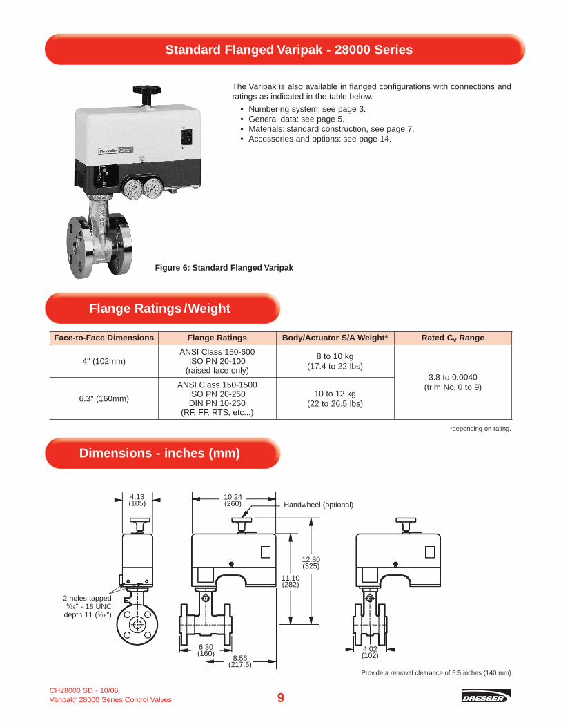
The Varipak is also available in flanged configurations with connections andratings as indicated in the table below.
• Numbering system: see page 3.• General data: see page 5.• Materials: standard construction, see page 7.• Accessories and options: see page 14.
Provide a removal clearance of 5.5 inches (140 mm)
*depending on rating.
Handwheel (optional)
2 holes tapped5⁄16" - 18 UNC
depth 11 (7⁄16")
4.13(105)
10.24(260)
6.30(160)
8.56(217.5)
11.10(282)
12.80(325)
4.02(102)
Face-to-Face Dimensions Flange Ratings Body/Actuator S/A Weight* Rated CV Range
4" (102mm)ANSI Class 150-600
ISO PN 20-100(raised face only)
8 to 10 kg(17.4 to 22 lbs)
3.8 to 0.0040(trim No. 0 to 9)
6.3" (160mm)
ANSI Class 150-1500ISO PN 20-250DIN PN 10-250
(RF, FF, RTS, etc...)
10 to 12 kg(22 to 26.5 lbs)
Figure 6: Standard Flanged Varipak
DV-195-28000 SD-f2.qxd 9/28/06 2:31 PM Page 9

CH28000 SD - 10/06Varipak® 28000 Series Control Valves 10
Varilog® Anti-Cavitation Varipak - 28000 MS Series
Specific Characteristics
Dimensions - inches (mm)
The Varilog multi-stage trim design provides unmatched anticavitation performance inlow flow applications.It minimizes erosion and vibrations, which typically leads to failure in conventional single-seated valves. The Varilog trim is available with the standard Varipak bodydesigns in either the flanged or flangeless configurations.• Numbering system: see page 3.• General data: see page 5.• Accessories and options: see page 14.• Materials: see chart below.
Provide a removal clearance of 5.5 inches (140 mm)
Standard Varipak (Stainless Steel) Bar Stock Body (For Non-Castable Material)
Handwheel (optional)
1⁄2" NPT3⁄4" NPT Optional1" NPT
2 holes tapped5/16" - 18 UNC
depth 11 (7/16")
)
4.13(105)
10.24(260)
1.30(33)
4.02(102) 8.56
(217.5)
11.10(282)
12.80(325)
1.10(28)
1.77(45)
Figure 7: Varilog Trim Subassembly
Rated CV Range Critical Flow Factor FL Temperature Range Materials
0.60 to 0.050(trim No. 3 to 6)
≥ 0.98 -20°F to +660°F(-29°C to +350°C)
Seat ASTM A 564 Gr. 630 Condition H900Type 17-4 PH St. St.
PlugOne part from solid Stellite No. 12or ASTM A 276 type 440 C St. St.
Other Parts Standard Construction: see page 7
DV-195-28000 SD-f2.qxd 9/28/06 2:31 PM Page 10

CH28000 SD - 10/06Varipak® 28000 Series Control Valves 11
High Pressure Varipak - 28000 HP Series
Dimensions - inches (mm)
Where very high upstream pressure occurs or where the pressure dropexceeds the pressure rating of the standard body (see page 8), a high pres-sure Varipak is the recommended choice.• Numbering system: see page 3.• General data: see page 5.• Accessories and options: see page 14.• Materials: see chart below.
Handwheel (optional)
1⁄2" NPT3⁄4" NPT Optional1" NPT
2 holes tapped5⁄16" - 18 UNC
depth 11 (7⁄16")
1⁄4" NPTSupply Connection
1⁄4" NPTInstrument Connection
4.13(105)
10.24(260)
1.10(28)
6.38(162)
8.56(217.5)
11.10(282)
12.80(325)
2.24(57)
Figure 8: High Pressure Varipak
Specific Characteristics
Rated CV Range Body Rating Seat Leakage Materials
0.60 to 0.0040(trim No. 3 to 9)
ANSI Class 2500ISO PN 420 Class IV
Body ASTM A 182 Gr. F 316LOptional: ASTM A182 Gr. F 316
Other Parts Standard Construction: see page 7
Valve Sizes X
inches mm inches mm
.5 15 3.15 80
.75 204.02 102
1 25
Provide a removal clearance of 5.5 inches (140 mm)
DV-195-28000 SD-f2.qxd 9/28/06 2:31 PM Page 11

CH28000 SD - 10/06Varipak® 28000 Series Control Valves 12
Provide a removal clearance of 5.5 inches (140 mm)
Handwheel(optional)
1⁄2" NPT3⁄4" NPT Optional1" NPT
2 holes tapped5/16" - 18 UNC
depth 11 (7/16")
)
4.13(105)
10.24(260)
1.30(33)
4.02(102) 8.56
(217.5)
11.10(282)
12.80(325)
Figure 9b: Plug and Bellows Subassembly
Bellows Seal Varipak - 28000 BS Series
Specific Characteristics
Dimensions - inches (mm)
A version of the Varipak with bellows seal is available for applications requiring zeroleakage at the packing box.
This type of valve is often needed for applications involving the handling of flammable,toxic or explosive fluids.
• Numbering system: see page 3.• General data: see page 5.• Accessories and options: see page 14.• Materials: see chart below.
Rated CVRange Body Rating Seat
LeakageOperatingPressures Materials
2.3 to 0.0040(trim No. 1 to 9)
ANSI Class 150-600ISO PN 10-100
Class IV800 psi at +212°F
(55 bar at +100°C)580 psi at +392°F
(40 bar at +200°C)
Body ASTM A 182 Gr. F 316LOptional: A182 Gr. F 316
Plug/BellowsSubassembly
Plug and Seat: Standard MaterialsBellows Assembly: 316L St. St.
Viton® O-rings
Other Parts Standard Construction: see page 7
Figure 9a: Bellows Seal Varipak
DV-195-28000 SD-f2.qxd 9/28/06 2:31 PM Page 12

CH28000 SD - 10/06Varipak® 28000 Series Control Valves 13
Figure 10:Cryogenic Varipak
Handwheel(optional)
2 holes tapped5⁄16" - 18 UNC
depth 11 (7⁄16")
1⁄4" NPTSupplyConnection1⁄4" NPTInstrumentConnection
4.13(105)
10.24(260)
1.30(33)
15.71(399)
8.56(217.5)
20.43(519)
22.13(562)
2.24(57)
4.02(102)
Cryogenic Varipak - 28000 EB Series
Specific Characteristics
Simplified maintenanceThe cryogenic Varipak meets the requirements of cryogenicprocesses requiring thermal insulation. An ‘insulating interface’sets up between the valve body (‘cold zone’) and the bodyextension located in the higher temperature area (‘warmzone’). The valve body assembly and its thermal extension arepositioned inside the ‘cold box’. The plug can be easilyremoved and inspected without disturbing the valve body. Thisprecludes any preliminary, complicated dismounting, and moreimportantly, prevents interfering in any way with the ‘cold box’.
BodyThe valve body, manufactured from a material suitable for lowtemperatures, maintains ductility in service. It can be conve-niently mounted to suit any specific piping needs. However,arrangements must be made so that the angle between thevalve axis and vertical does not exceed 60°.
The bonnet is located away from the cryogenic fluid, whichmeans that the body gasket is not inside the cold zone. Thisdesign prevents any leakage of the cryogen into the insulatedzone.
Body extensionThe body extension and coupling sleeve are thin-walled metaltubes so as to minimize the inflow of heat by conduction. Theannular space is reduced in order to exclude any convectioncurrents.
PlugThe design of the plug allows the working parts to be perfectlycentered in relation to the seat and provides a uniform temper-ature zone for the guiding.• Numbering system: see page 3.• General data: see page 5.• Accessories and options: see page 14.• Materials: see chart below.
Dimensions - inches (mm)
Rated CVRange
Temperature Range Body Rating Seat
Leakage Materials
3.8 to 0.10(trim No. 0 to 5)
-455°F to +300°F(-270°C to + 150°C)
ANSI Class 150-600 ISO PN 20-100
excepted trim No. 0:ANSI Class 150-300
ISO PN 20-50
Class IV
Body andExtension
ASTM A 182 Gr. F 316L
Plug/Stem Standard Material
SeatTrim No. 0: Standard Material
Trim No. 1 to 5: ASTM A 564 Gr. 630Condition H900 Type 17-4 PH. St. St.
O-ring SeatGasket
PTFE
Other Parts Standard Construction: see page 7
Provide a removal clearance of 5.5 inches (140 mm)
DV-195-28000 SD-f2.qxd 9/28/06 2:31 PM Page 13

CH28000 SD - 10/06Varipak® 28000 Series Control Valves 14
Accessories and Options
Typepneumatic, force balance
Mountingbuilt-in bracket in actuator
Actiondirect: increasing instrument signalincreases air output
Characteristicslinear
Instrument signal200 to 1000, 400 to 2050 or 3 to 15, 6 to 30 or 3 to 27 psi(200 to 1850 mbar)3 to 9, and 9 to 15 psi(200 to 600 and 600 to 1000 mbar)split range
Connections1/4" NPT instrument and supply —1/8" NPT output
Average air consumption0.15 scfm at 30 psi supply (0.26 Nm3/h at 2.1 bar supply)
Max. air output4.20 scfm (7 Nm3/h)
Supply pressure effect0.05% of full stroke variation perpsi supply pressure change(0.07% per 100 mbar)
Open loop gain70
Linearity± 0.5%
Sensitivity0.1%
Repeatability0.1%
Full stroke timeless than one second
Weight3.3 lbs (1.5 kg)
Other AccessoriesProximity sensors and limit switchesDigital positioners - HART® and FieldbusFoundationHandwheel, airsets and solenoid valves
Figure 11: Model 7700PPneumatic Positioner
Figure 12: Model 7700EElectropneumatic Positioner
Electropneumatic Positioner (Model 7700E)
Pneumatic Positioner (Model 7700P)
Typeelectropneumatic, force balance
Mountingcompact, without external linkageto the actuator (see Fig. 8)
Actiondirect: increasing instrument signalincreases air output
Characteristicslinear
Instrument signal4-20 mA
Air connections1/4" NPT supply - 1/8" NPT output
Average air consumption0.24 scfm (0.4 Nm3/h)
Electrical connections1/2" NPT or M20
Weight7.7 lbs (3.5 kg)
Hazardous Location ProtectionATEX Approvals (94/9/EC Directive)
ExplosionproofNo. SIRA 02 ATEX 1274Intrinsic SafetyNo. SIRA 02 ATEX 2277 X
FM (Factory Mutual) ApprovalsExplosionproofIntrinsic Safety Non-incendive and Dust-ignitionproof
CSA Approvals (Canadian Standards Association)
ExplosionproofIntrinsic Safety Non-incendive
DV-195-28000 SD-f2.qxd 9/28/06 2:31 PM Page 14

CH28000 SD - 10/06Varipak® 28000 Series Control Valves 15
Standard Actuator Options
Figure 15: Varipak with 7700EElectropneumatic Positioner
Figure 14: Varipak with Non-AdjustableCv Actuator (cover removed)
Figure 13: Non Adjustable Cv Actuator
Figure 16: Adjustable Cv Actuator
DV-195-28000 SD-f2.qxd 9/28/06 2:31 PM Page 15

Sales Office Locations
CH28000 SD - 10/06Varipak® 28000 Series Control ValvesCopyright 2006 Dresser, Inc. All rights reserved.
INDIADresser Valve India Pvt. Ltd.305/306, “Midas”, Sahar PlazaMathurdas Vasanji RoadJ.B. Nagar, Andheri EastMumbai, 400059, IndiaPhone: +91-22-8354790Fax: +91-22-8354791
Dresser Valve India Pvt. Ltd.205, Mohta Building4 Bhikaiji Cama PlaceNew Delhi, 110 066, IndiaPhone: +91-11-2-6164175Fax: +91-11-5-1659635
ITALYDresser Italia S.r.l.Masoneilan OperationsVia Cassano, 7780020 Casavatore, Napoli ItalyPhone: +39-081-7892-111Fax: +39-081-7892-208
JAPANNiigata Masoneilan Co. Ltd. (NIMCO)20th Floor, Marive East TowerWBG 2-6 Nakase, Mihama-ku,Chiba-shi, Chiba 261-7120 JapanPhone: +81-43-297-9222Fax: +81-43-299-1115
KOREADresser Korea Inc.2109 Kuk Dong Building60-1, ChoongMoo-ro 3-kaJoong-gu, Seoul, Korea 100-705Phone: +82-2-2274-0748Fax: +82-2-2274-0720
KUWAITDresser Flow SolutionsMiddle East Operations10th Floor, Al Rashed ComplexFahad Salem Street, P.O. Box 242Safat, 13003, KuwaitPhone: +965-9061157Fax: +965-3987879
MALAYSIADresser Flow SolutionsBusiness Suite, 19A-9-1, Level 9UOA Centre, No. 19, Jalan Pinang50450 Kuala Lumpur, West MalaysiaPhone: +60-3-2161-0322Fax: +60-3-2163-3612
MEXICODresser Valve de Mexico, S.A. de C.V.Henry Ford No. 114, Esq. FultonFraccionamiento Industrial SanNicolas54030 Tlalnepantla Estado de MexicoPhone: 52-5-310-9863Fax: 52-5-310-5584
THE NETHERLANDSDresser Valves EuropeSteenhouwerstraat 113194 AG Hoogvliet, The NetherlandsPhone: +31-10-438-4122Fax: +31-10-438-4443
BELGIUMDresser Valves EuropeBoulevard du Souverain 207 B2Vorstlaan,B-1160 Brussels, BelgiumPhone: +32-2-344-0970Fax: +32-2-344-1123
BRAZILDresser Industria e Comercio LtdaDivisao MasoneilanRua Funchal, 129 - Conj. 5A04551-060 - Sao Paulo - SP BrazilPhone: 55-11-2146-3600Fax: 55-11-2146-3610
CANADAOntarioDresser - MasoneilanDI Canada, Inc.835 Harrington Court, 2nd FloorBurlington, Ontario L7N 3P3, CanadaPhone: 905-335-3529Fax: 905-336-7628
CHINADresser Flow SolutionsBeijing Rep. OfficeSuite 1703, Capital Mansion6 Xinyuannan Rd. Chaoyang DistrictBeijing 100004, ChinaPhone: +86-10-8486-4515Fax: +86-10-8486-5305
FRANCEMasoneilan - Dresser ProduitsIndustrielsEnergy 5130/190 Boulevard de Verdun92413 Courbevoie cedex, FrancePhone: +33-1-4904-9000Fax: +33-1-4904-9010
Dresser Produits Industriels S.A.S.,Masoneilan Customer Service Centre55 rue de la Mouche, Zone Industrielle69540 Irigny, FrancePhone: +33-4-72-39-06-29Fax: +33-4-72-39-21-93
GERMANYDresser Valves Europe GmbHHeiligenstrasse 75Viersen D-41751, GermanyPhone: +49-2162-8170-0Fax: +49-2162-8170-280
Dresser Valves Europe GmbHUhlandstrasse 5860314 Frankfurt, GermanyPhone: +49-69-439350Fax: +49-69-4970802
RUSSIADS ControlsNekhinskaya Street, 61Veliky NovgorodRussia, 173021Phone: +7-8162-15-7898Fax: +7-8162-15-7921
SAUDI ARABIADresser AL RushaidValve & Instrument Co., Ltd.(Darvico)P.O. Box 10145Jubail Industrial City 31961,Saudi ArabiaPhone: +966-3-341-0278Fax: +966-3-341-7624
SINGAPOREDresser Singapore Pte Ltd.16 Tuas Avenue 8Singapore 639231Phone: +65-6-6861-6100Fax: +65-6-6861-7172
SOUTH AFRICADresser LimitedP.O. Box 223416 Edendale RoadEastleigh, Edenvale 1610Republic of South AfricaPhone: +27-11-452-1550Fax: +27-11-452-6542
SPAINMasoneilan S.A.C/Murcia 39 C08830 Sant Boi de LlobregatBarcelona, SpainPhone: +34-93-652-6430Fax: +34-93-652-6444
UNITED ARAB EMIRATESDresser Flow SolutionsMiddle East OperationsP.O. Box 61302Roundabout 8Units JA01 & JA02Jebel Ali Free ZoneDubai, U. A. E.Phone: +971-4-8838-752Fax: +971-4-8838-038
UNITED KINGDOMDI U.K. Ltd.East GillibrandsSkelmersdale,Lancashire WN8 9TU, EnglandPhone: +44-1695-52600Fax: +44-1695-52601
DI U.K. Ltd.Unit 4, Suite 1.1, Nobel HouseGrand Union Office ParkPacket Boat LaneUxbridge, Middlesex UB8 2GHPhone: +44-1895-454-900Fax: +44-1895-454-919
UNITED STATESDresser - Masoneilan85 Bodwell StreetAvon, MA 02322-1190Phone: 508-586-4600Fax: 508-427-8971
Dresser - Masoneilan4841 Leopard StreetCorpus Christi, TX 78408-2621Phone: 361-881-8182Fax: 361-881-8246
Dresser - MasoneilanDresser Direct1250 Hall CourtDeer Park, TX 77536Phone: 281-884-1000Fax: 281-884-1010
Dresser Flow Solutions(Contractor Sales)16240 Port Northwest DriveHouston, TX 77041Phone: 832-590-2303Fax: 832-590-2529
Dresser - Masoneilan12015 Mora Drive, Unit 2Santa Fe Springs, CA 90670Phone: 562-941-7610Fax: 562-941-7810
www.masoneilan.com
DV-195-28000 SD-f2.qxd 9/28/06 2:31 PM Page b