Embed Size (px)
DESCRIPTION
Dust Explosion Hazard Assessment and Control An Overview. Vahid Ebadat, Ph.D. Chilworth Technology, Inc. 250 Plainsboro Road, Building 7 Plainsboro, NJ 08536 TEL: 609 799 4449 FAX: 609 799 5559 email: [email protected] http://www.chilworth.com Presentation at - PowerPoint PPT Presentation
Citation preview

ChilworthTechnology
1
Dust Explosion Hazard Assessment and ControlAn Overview
Vahid Ebadat, Ph.D.
Chilworth Technology, Inc.
250 Plainsboro Road, Building 7Plainsboro, NJ 08536TEL: 609 799 4449FAX: 609 799 5559
email: [email protected]://www.chilworth.com
Presentation at American Industrial Hygiene Conference & Exposition - Pharmaceutical Forum
June 3rd, 2009, Toronto, Canada
ChilworthTechnology
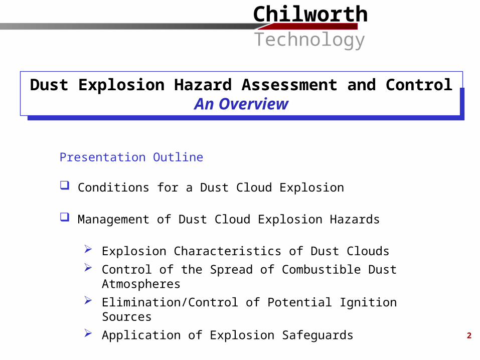
Presentation Outline
Conditions for a Dust Cloud Explosion
Management of Dust Cloud Explosion Hazards
Explosion Characteristics of Dust Clouds Control of the Spread of Combustible Dust Atmospheres Elimination/Control of Potential Ignition Sources Application of Explosion Safeguards
2
Dust Explosion Hazard Assessment and ControlAn Overview
ChilworthTechnology
3
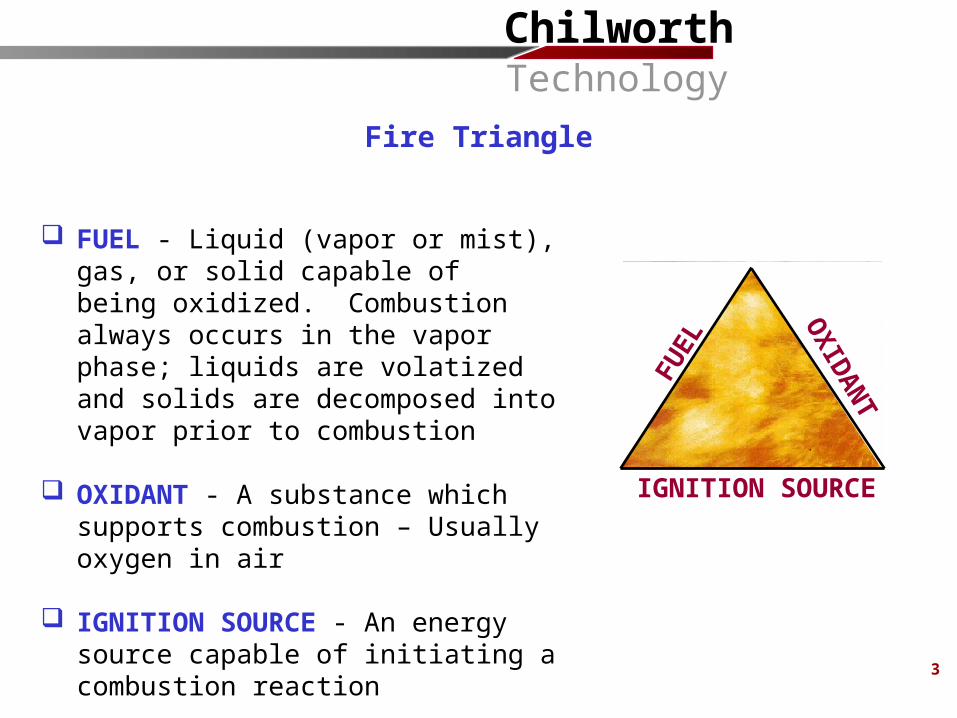
FUEL - Liquid (vapor or mist), gas, or solid capable of being oxidized. Combustion always occurs in the vapor phase; liquids are volatized and solids are decomposed into vapor prior to combustion
OXIDANT - A substance which supports combustion – Usually oxygen in air
IGNITION SOURCE - An energy source capable of initiating a combustion reaction
IGNITION SOURCE
FUEL
OXIDANTFire Triangle

ChilworthTechnology
4
A number of conditions must exist simultaneously for a dust explosion to occur:
Dust must be explosible (combustible, Flammable)
Dust must be airborne
Dust concentrations must be within explosible range
Dust must have particle size distribution capable of propagating a flame
The atmosphere in which the dust cloud is present must be capable of supporting combustion
An ignition source with sufficient energy to initiate flame propagation must be present
Conditions Required for Dust Cloud Explosions to Occur
ChilworthTechnology
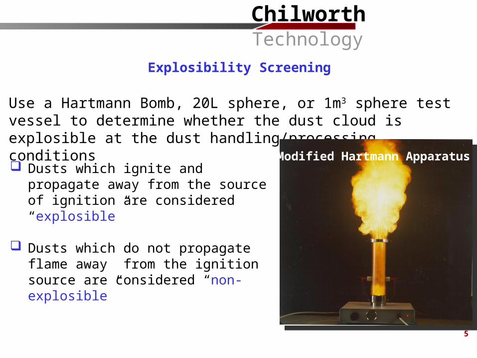
Use a Hartmann Bomb, 20L sphere, or 1m3 sphere test vessel to determine whether the dust cloud is explosible at the dust handling/processing conditions
Dusts which ignite and propagate away from the source of ignition are considered “explosible”
Dusts which do not propagate flame away from the ignition source are considered “non-explosible”
Modified Hartmann Apparatus
Explosibility Screening
5
ChilworthTechnology
66
A number of conditions must exist simultaneously for a dust explosion to occur:
Dust must be explosible (combustible, Flammable)
Dust must be airborne
Dust concentrations must be within explosible range
Dust must have particle size distribution capable of propagating a flame
The atmosphere in which the dust cloud is present must be capable of supporting combustion
An ignition source with sufficient energy to initiate flame propagation must be present
Conditions Required for Dust Cloud Explosions to Occur
ChilworthTechnology
7
Site Audit:
Understand process operations and review of all available information (drawings, specifications, process/operation descriptions)
Identification of locations where combustible dust cloud atmospheres are or could be present during normal and abnormal operating conditions
Identification of potential ignition sources that could be present under normal and abnormal conditions
On-site electrostatic measurements (electrical field, electrical continuity measurements, etc.), where applicable
Understanding of the explosion characteristics of the dust(s)
Proper process and facility design to prevent and/or minimize the occurrence of dust explosions and protect people and facilities against their consequences
Regular inspection and maintenance of equipment to minimize ignition sources and dust releases
Management of Dust Cloud Explosion Hazards
ChilworthTechnology
How easily will the dust cloud ignite? Minimum Ignition Energy (dust cloud) Minimum Ignition Temperature (dust cloud and dust layer) Thermal Instability
Electrostatic Properties Electrostatic Chargeability Resistivity / Conductivity
What will happen if the dust cloud does ignite? (Consequences of Ignition) Maximum Explosion Pressure Maximum Rate of Pressure Rise
Ensuring Safety by Avoiding/Controlling Flammable Atmospheres? Minimum Explosible Concentration Limiting Oxygen Concentration
Laboratory Testing to Understand Explosion Characteristics of Dusts
8
ChilworthTechnology
9
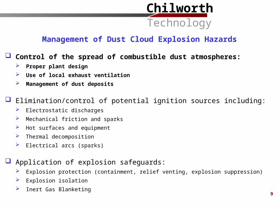
Control of the spread of combustible dust atmospheres: Proper plant design Use of local exhaust ventilation Management of dust deposits
Elimination/control of potential ignition sources including: Electrostatic discharges Mechanical friction and sparks Hot surfaces and equipment Thermal decomposition Electrical arcs (sparks)
Application of explosion safeguards: Explosion protection (containment, relief venting, explosion suppression) Explosion isolation Inert Gas Blanketing
Management of Dust Cloud Explosion Hazards
ChilworthTechnology
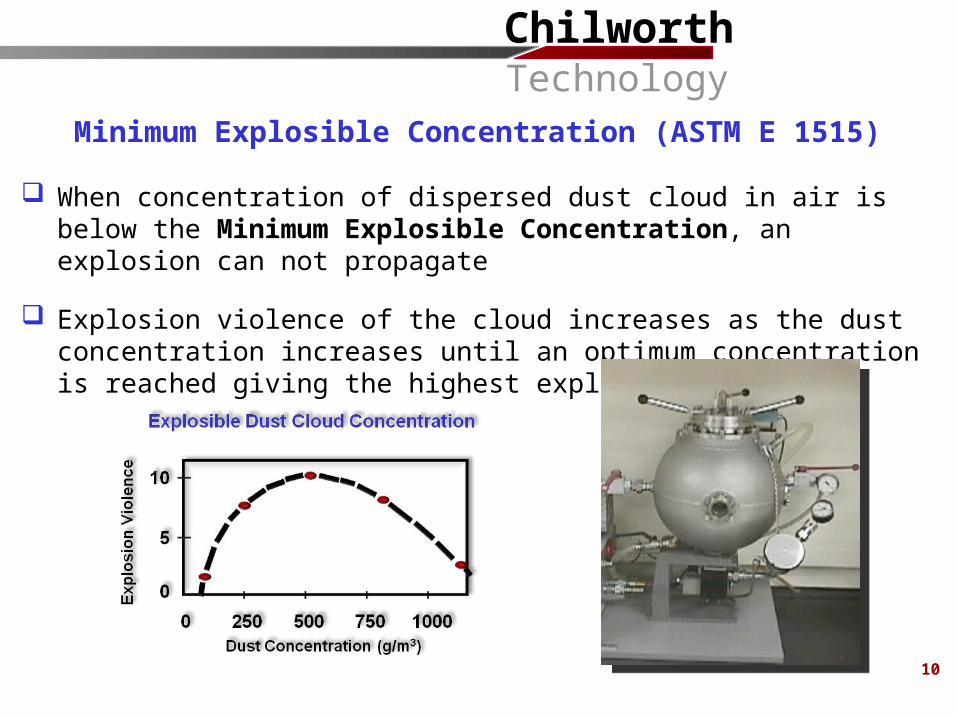
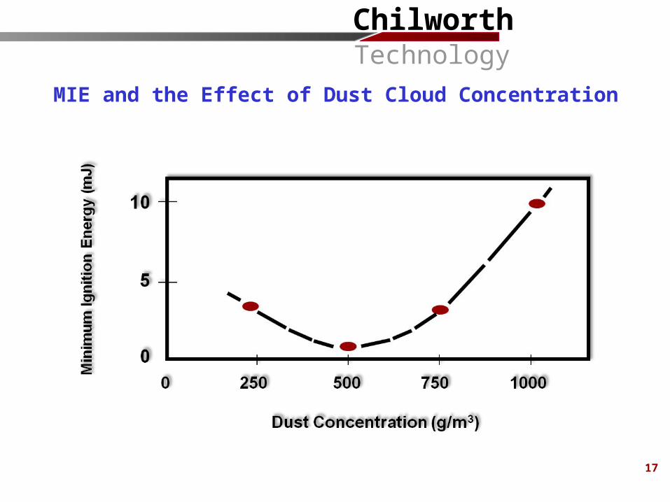
When concentration of dispersed dust cloud in air is below the Minimum Explosible Concentration, an explosion can not propagate
Explosion violence of the cloud increases as the dust concentration increases until an optimum concentration is reached giving the highest explosion violence
Minimum Explosible Concentration (ASTM E 1515)
10
ChilworthTechnology
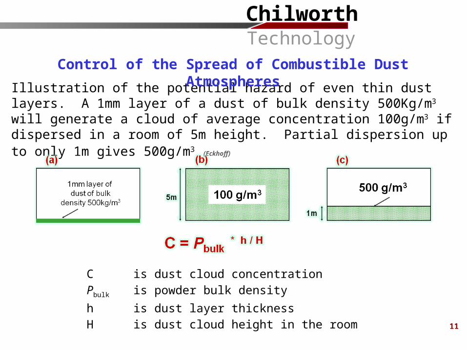
Illustration of the potential hazard of even thin dust layers. A 1mm layer of a dust of bulk density 500Kg/m3 will generate a cloud of average concentration 100g/m3 if dispersed in a room of 5m height. Partial dispersion up to only 1m gives 500g/m3 (Eckhoff)
C is dust cloud concentrationPbulk is powder bulk densityh is dust layer thicknessH is dust cloud height in the room
Control of the Spread of Combustible Dust Atmospheres
11
ChilworthTechnology
Equipment should be maintained and operated in a manner that minimizes the escape of dust
Continuous local exhaust ventilation should be provided for processes where combustible dust is liberated in normal operation so as to minimize the escape of dust. The dust should be conveyed to dust collectors
Regular cleaning frequencies should be established for floors and horizontal surfaces, such as ducts, pipes, hoods, ledges, and beams, to minimize dust accumulations within operating areas of the facility
Control of the Spread of Combustible Dust Atmospheres
13
ChilworthTechnology
15
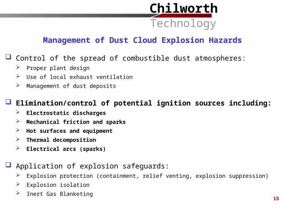
Management of Dust Cloud Explosion Hazards
Control of the spread of combustible dust atmospheres: Proper plant design Use of local exhaust ventilation Management of dust deposits
Elimination/control of potential ignition sources including: Electrostatic discharges Mechanical friction and sparks Hot surfaces and equipment Thermal decomposition Electrical arcs (sparks)
Application of explosion safeguards: Explosion protection (containment, relief venting, explosion suppression) Explosion isolation Inert Gas Blanketing
ChilworthTechnology
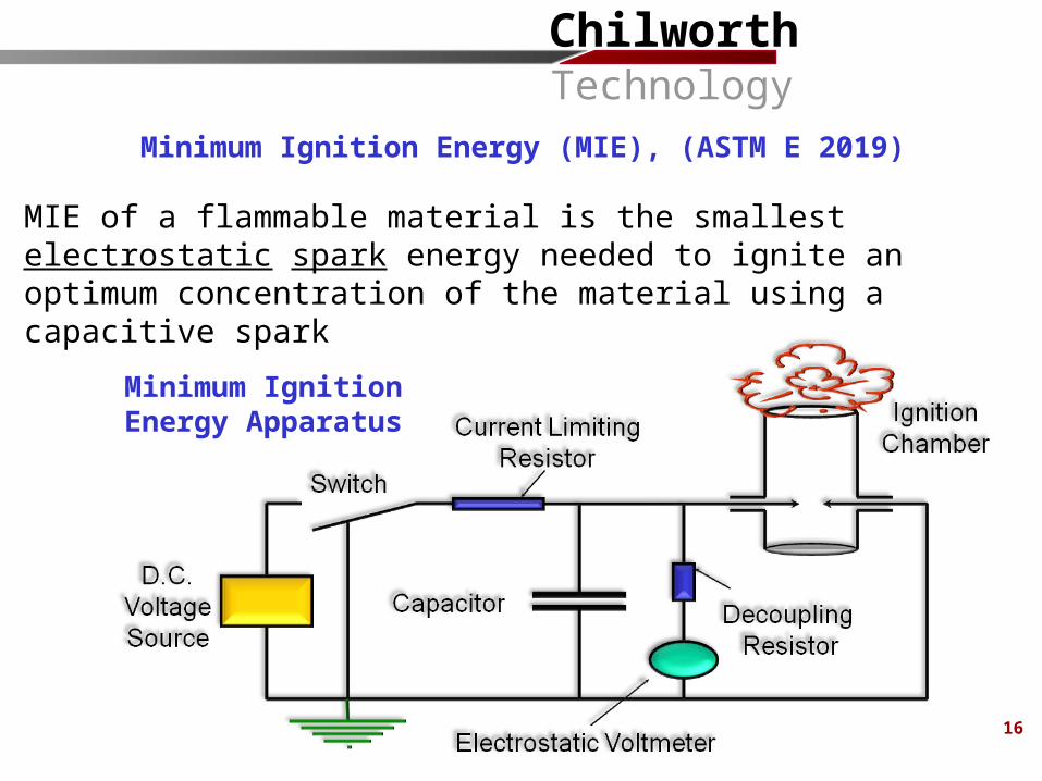
Minimum Ignition Energy Apparatus
MIE of a flammable material is the smallest electrostatic spark energy needed to ignite an optimum concentration of the material using a capacitive spark
Minimum Ignition Energy (MIE), (ASTM E 2019)
16
ChilworthTechnology
MIE and the Effect of Dust Cloud Concentration
17
ChilworthTechnology
18
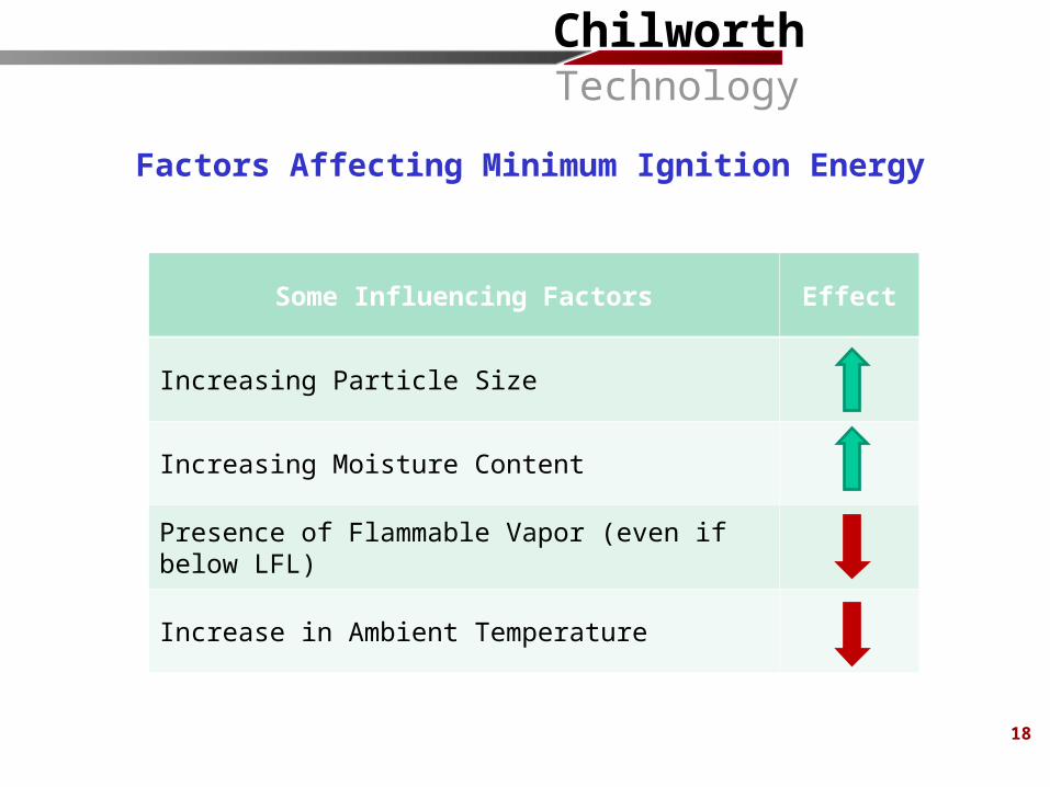
Factors Affecting Minimum Ignition Energy
Some Influencing Factors Effect
Increasing Particle Size
Increasing Moisture Content
Presence of Flammable Vapor (even if below LFL)
Increase in Ambient Temperature
ChilworthTechnology
19
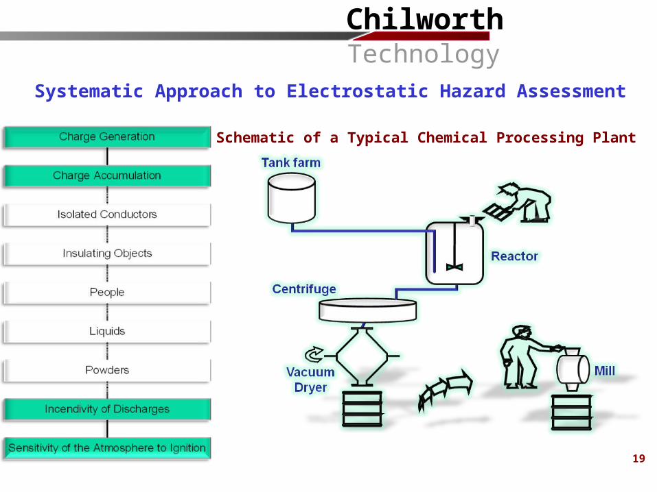
Systematic Approach to Electrostatic Hazard Assessment
Schematic of a Typical Chemical Processing Plant
ChilworthTechnology
20
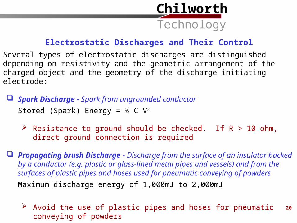
Several types of electrostatic discharges are distinguished depending on resistivity and the geometric arrangement of the charged object and the geometry of the discharge initiating electrode:
Spark Discharge - Spark from ungrounded conductorStored (Spark) Energy = ½ C V2
Resistance to ground should be checked. If R > 10 ohm, direct ground connection is required
Propagating brush Discharge - Discharge from the surface of an insulator backed by a conductor (e.g. plastic or glass-lined metal pipes and vessels) and from the surfaces of plastic pipes and hoses used for pneumatic conveying of powders Maximum discharge energy of 1,000mJ to 2,000mJ
Avoid the use of plastic pipes and hoses for pneumatic conveying of powders Avoid plastic containers/liners for powders with high charge densities
Electrostatic Discharges and Their Control
ChilworthTechnology
21
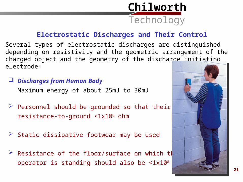
Several types of electrostatic discharges are distinguished depending on resistivity and the geometric arrangement of the charged object and the geometry of the discharge initiating electrode:
Discharges from Human BodyMaximum energy of about 25mJ to 30mJ
Personnel should be grounded so that their resistance-to-ground <1x10⁸ ohm
Static dissipative footwear may be used
Resistance of the floor/surface on which theoperator is standing should also be <1x10⁸ ohm
Electrostatic Discharges and Their Control
ChilworthTechnology
22
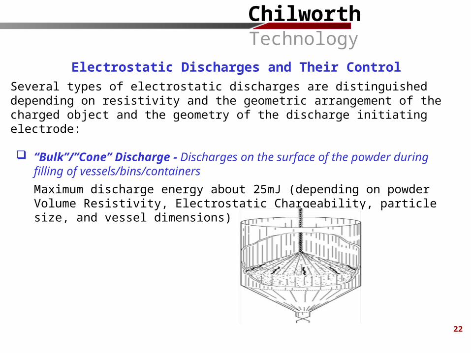
Several types of electrostatic discharges are distinguished depending on resistivity and the geometric arrangement of the charged object and the geometry of the discharge initiating electrode:
“Bulk”/”Cone” Discharge - Discharges on the surface of the powder during filling of vessels/bins/containers Maximum discharge energy about 25mJ (depending on powder Volume Resistivity, Electrostatic Chargeability, particle size, and vessel dimensions)
Electrostatic Discharges and Their Control
ChilworthTechnology
23
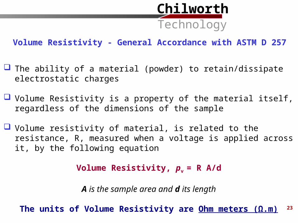
The ability of a material (powder) to retain/dissipate electrostatic charges
Volume Resistivity is a property of the material itself, regardless of the dimensions of the sample
Volume resistivity of material, is related to the resistance, R, measured when a voltage is applied across it, by the following equation
Volume Resistivity, pv = R A/d
A is the sample area and d its length
The units of Volume Resistivity are Ohm meters (Ω.m)
Volume Resistivity - General Accordance with ASTM D 257
ChilworthTechnology
24
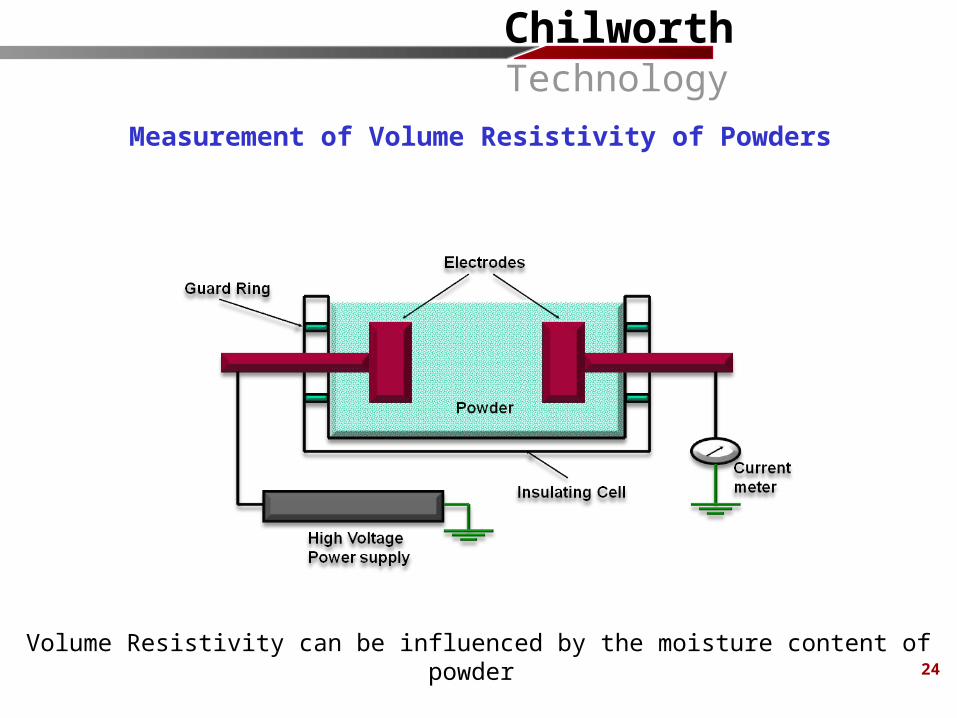
Measurement of Volume Resistivity of Powders
Volume Resistivity can be influenced by the moisture content of powder
ChilworthTechnology
25
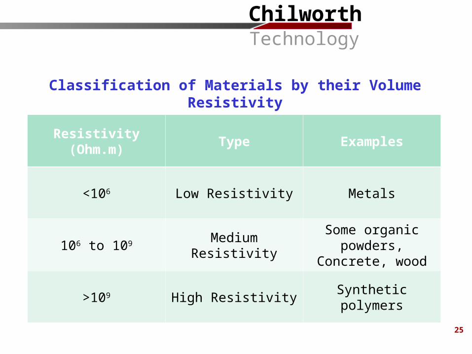
Resistivity (Ohm.m) Type Examples
<106 Low Resistivity Metals
106 to 109 Medium ResistivitySome organic
powders, Concrete, wood
>109 High Resistivity Synthetic polymers
Classification of Materials by their Volume Resistivity
ChilworthTechnology
26
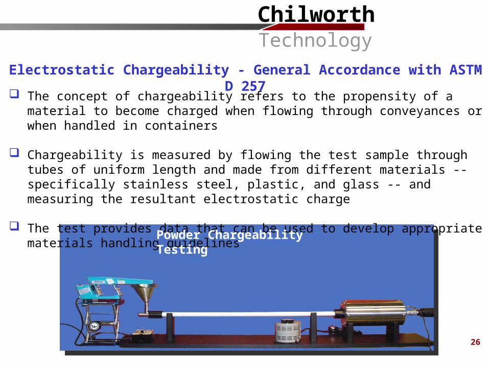
The concept of chargeability refers to the propensity of a material to become charged when flowing through conveyances or when handled in containers
Chargeability is measured by flowing the test sample through tubes of uniform length and made from different materials -- specifically stainless steel, plastic, and glass -- and measuring the resultant electrostatic charge
The test provides data that can be used to develop appropriate materials handling guidelines
Powder Chargeability Testing
Electrostatic Chargeability - General Accordance with ASTM D 257
ChilworthTechnology
27
Static charge can build up on powders with Volume Resistivity >109 ohm.m or if powder is in insulating or ungrounded conductive vessels
Control measures depend on Minimum Ignition Energy of the dust cloud and Volume Resistivity of the powder :
Volume Resistivity < 109 Ohm.mNo electrostatic charge accumulation if powder is handled in grounded conductive plant
Volume Resistivity > 109 Ohm.m and Minimum Ignition Energy >25mJNo electrostatic ignition hazard in grounded conductive plant
Control of Electrostatic Hazards - Discharges from Powders
ChilworthTechnology
28
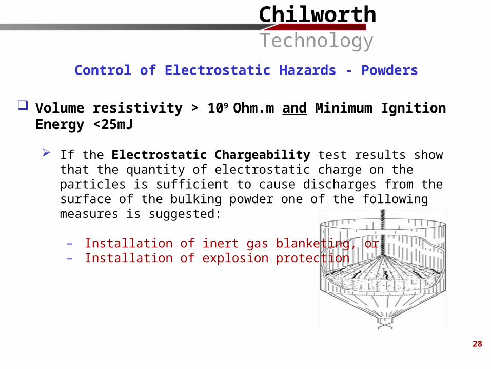
Control of Electrostatic Hazards - Powders
Volume resistivity > 109 Ohm.m and Minimum Ignition Energy <25mJ
If the Electrostatic Chargeability test results show that the quantity of electrostatic charge on the particles is sufficient to cause discharges from the surface of the bulking powder one of the following measures is suggested:
– Installation of inert gas blanketing, or– Installation of explosion protection
ChilworthTechnology
29
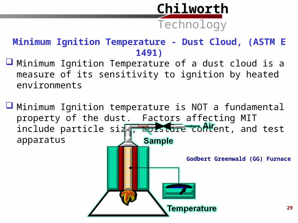
Minimum Ignition Temperature of a dust cloud is a measure of its sensitivity to ignition by heated environments
Minimum Ignition temperature is NOT a fundamental property of the dust. Factors affecting MIT include particle size, moisture content, and test apparatus
Minimum Ignition Temperature - Dust Cloud, (ASTM E 1491)
Godbert Greenwald (GG) Furnace
ChilworthTechnology
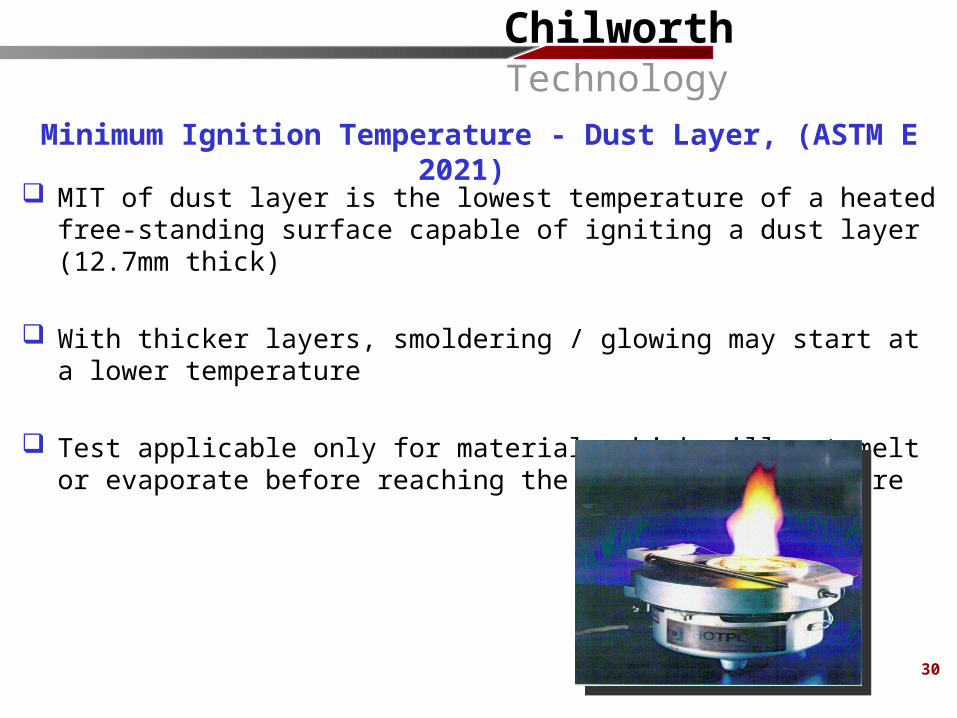
MIT of dust layer is the lowest temperature of a heated free-standing surface capable of igniting a dust layer (12.7mm thick)
With thicker layers, smoldering / glowing may start at a lower temperature
Test applicable only for materials which will not melt or evaporate before reaching the ignition temperature
Minimum Ignition Temperature - Dust Layer, (ASTM E 2021)
30
ChilworthTechnology
31
Minimum Ignition Temperature
Minimum Ignition Temperature tests provide information on:
Sensitivity to ignition by:o hot environments and surfaces of some processing equipment and planto hot surfaces caused by overheating of bearings and other mechanical
parts due to mechanical failureo frictional sparks
Maximum exposure temperature (Temperature Rating) for electrical equipment
ChilworthTechnology
Ignition of bulk powders can occur by a process of self-heating
Ignition occurs when the temperature of the powder is raised to a level at which the heat liberated by the exothermic reaction is sufficient to exceed the heat losses and to produce runaway increase in temperature
The minimum ambient temperature for self-ignition of a powder depends mainly on the nature of the powder and on its dimensions
Thermal Instability (Self-Heating)
33
ChilworthTechnology
34
ChilworthTechnology
35
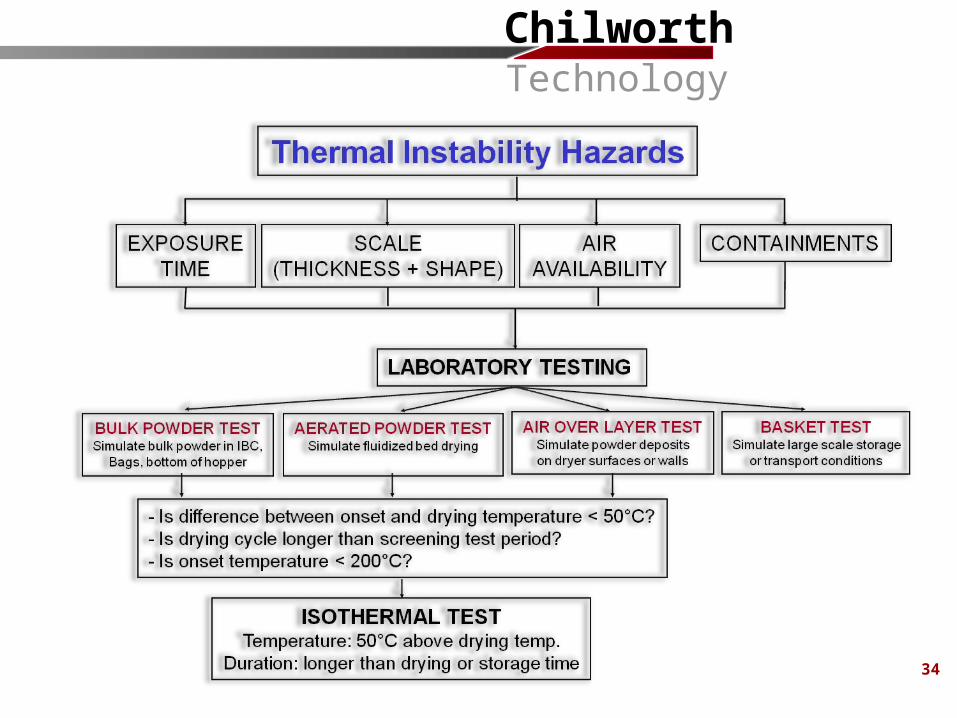
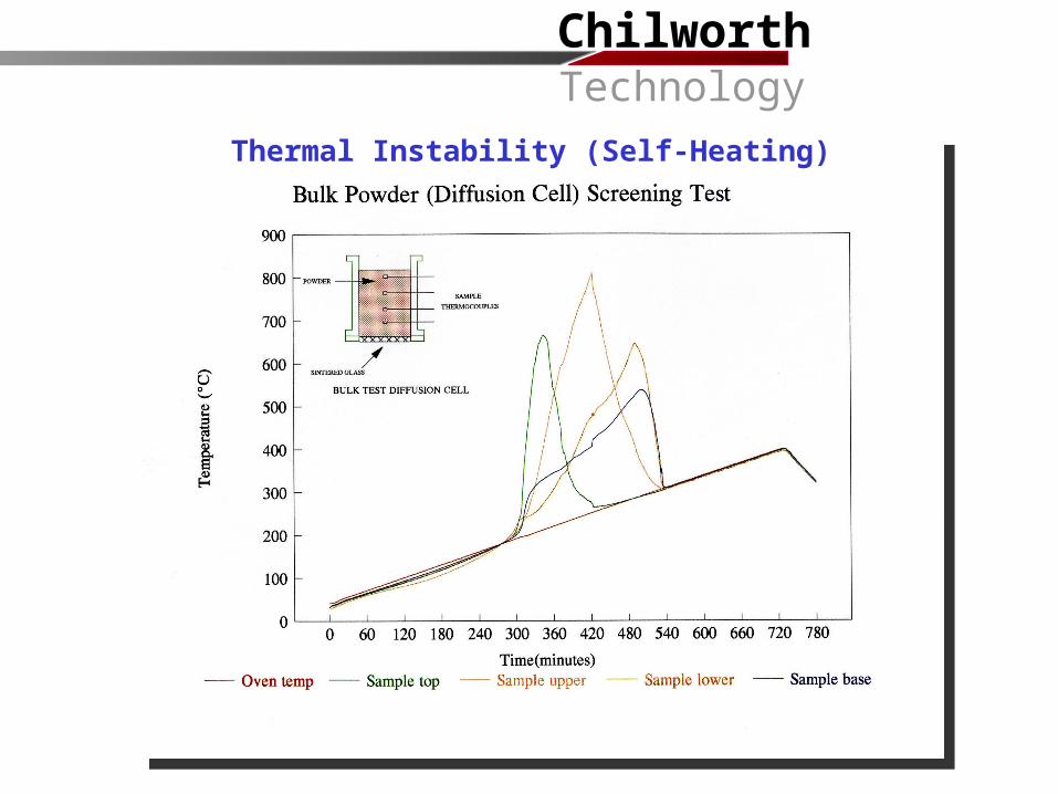
Thermal Instability (Self-Heating)
ChilworthTechnology
Preventing overloading of processing plant (grinders, conveyors, etc.)
Isolation or shielding of hot surfaces
Prevention/removal of dust accumulations on hot surfaces
Use of approved electrical equipment (correct temperature rating)
Prevent overheating due to misalignment, loose objects, belt-slip/rubbing etc. by regular inspection and maintenance of plant
Prevent foreign material from entering the system when such foreign material presents an ignition hazard. Consider use of screens, electromagnets, pneumatic separators, etc.
Hot work operations should be controlled by a hot work permit system in accordance with NFPA 51B, Standard for Fire Prevention During Welding, Cutting and Other Hot Work
Control of Heat Sources and Frictional Sparks
37
ChilworthTechnology
39
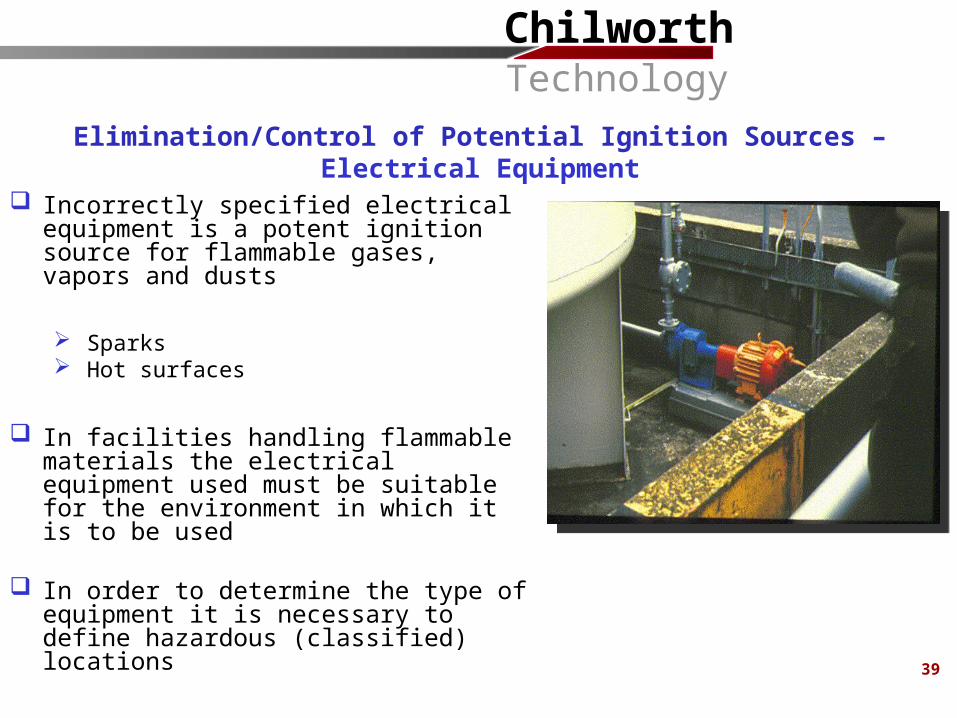
Incorrectly specified electrical equipment is a potent ignition source for flammable gases, vapors and dusts
Sparks Hot surfaces
In facilities handling flammable materials the electrical equipment used must be suitable for the environment in which it is to be used
In order to determine the type of equipment it is necessary to define hazardous (classified) locations
Elimination/Control of Potential Ignition Sources – Electrical Equipment
ChilworthTechnology
40
Electrical area classifications defined under Article 500 of the National Electrical
Code (NFPA 70)
The intent of Article 500 is to prevent electrical equipment from providing a means of ignition for an ignitable atmosphere
Two classes of hazardous locations:
Class I Flammable gases or vapors (NFPA 497) Class II Combustible dusts (NFPA 499)
Two divisions of hazardous locations:
Division 1 Normally or frequently present Division 2 Not normally present, but possible
Electrical Area Classification
ChilworthTechnology
42
Dust-tight equipment and good maintenance reduces the extent of classified areas
Effective dust removal (ventilated hoods and pickup points) and excellent housekeeping reduces the extent of a classified area
Where there are walls that limit the travel of the dust particles, area classifications do not extend beyond the walls
Extent of Class II Locations
ChilworthTechnology
43
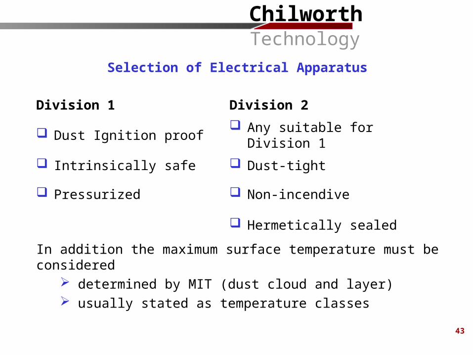
Division 1 Division 2
Dust Ignition proof Any suitable for Division 1
Intrinsically safe Dust-tight
Pressurized Non-incendive
Hermetically sealed
In addition the maximum surface temperature must be considered determined by MIT (dust cloud and layer) usually stated as temperature classes
Selection of Electrical Apparatus
ChilworthTechnology
44
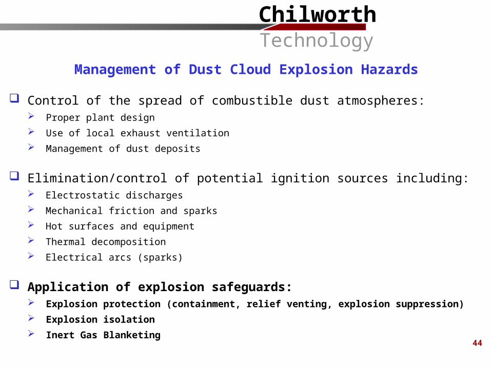
Management of Dust Cloud Explosion Hazards
Control of the spread of combustible dust atmospheres: Proper plant design Use of local exhaust ventilation Management of dust deposits
Elimination/control of potential ignition sources including: Electrostatic discharges Mechanical friction and sparks Hot surfaces and equipment Thermal decomposition Electrical arcs (sparks)
Application of explosion safeguards: Explosion protection (containment, relief venting, explosion suppression) Explosion isolation Inert Gas Blanketing
ChilworthTechnology
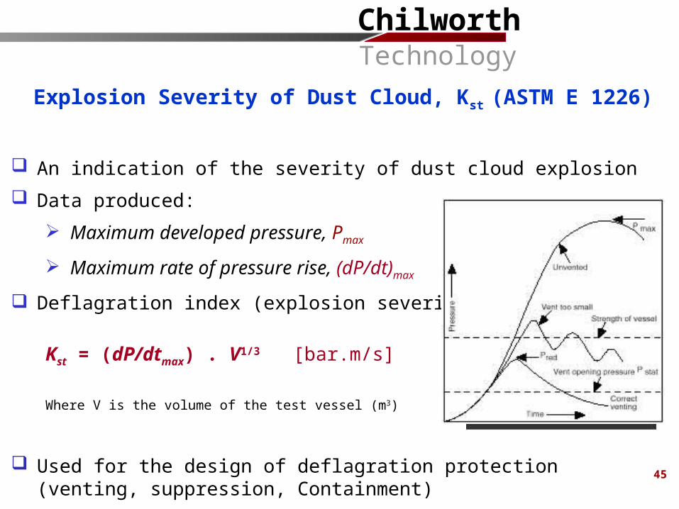
An indication of the severity of dust cloud explosion Data produced:
Maximum developed pressure, Pmax
Maximum rate of pressure rise, (dP/dt)max
Deflagration index (explosion severity) Kst
Kst = (dP/dtmax) . V1/3 [bar.m/s]
Where V is the volume of the test vessel (m3)
Used for the design of deflagration protection (venting, suppression, Containment)
Explosion Severity of Dust Cloud, Kst (ASTM E 1226)
20-Liter Sphere Apparatus
45
ChilworthTechnology
46
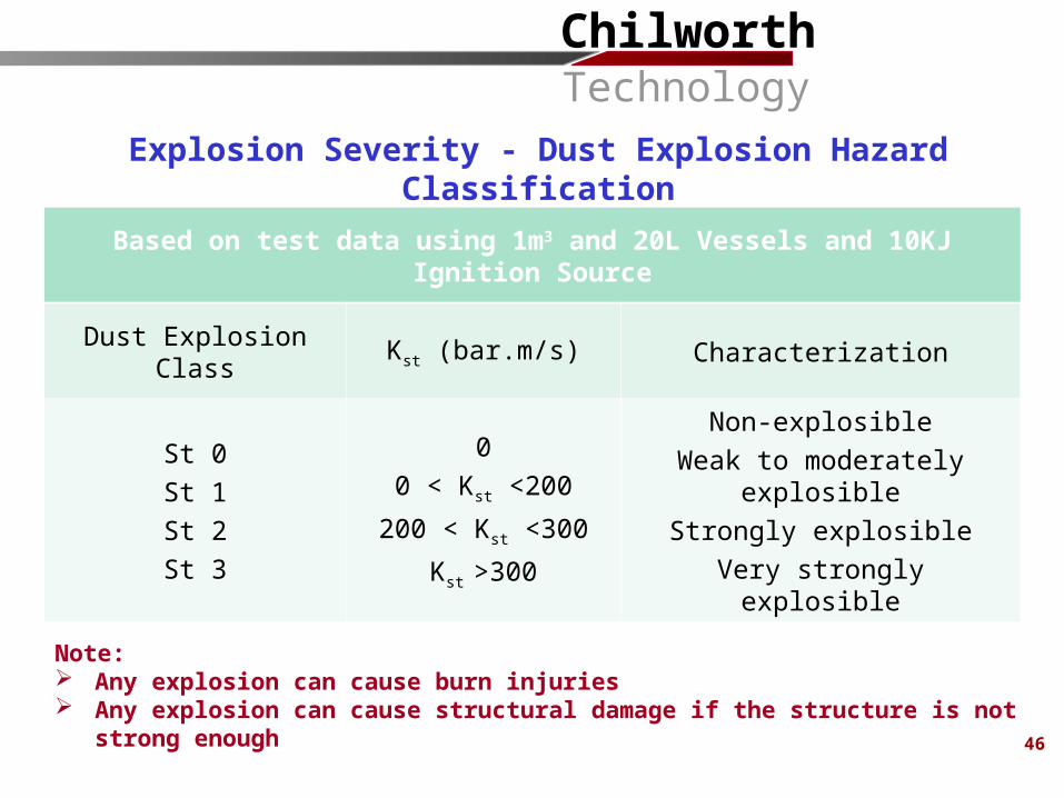
Based on test data using 1m3 and 20L Vessels and 10KJ Ignition Source
Dust Explosion Class Kst (bar.m/s) Characterization
St 0St 1St 2St 3
00 < Kst <200
200 < Kst <300
Kst >300
Non-explosibleWeak to moderately explosible
Strongly explosibleVery strongly explosible
Explosion Severity - Dust Explosion Hazard Classification
Note: Any explosion can cause burn injuries Any explosion can cause structural damage if the structure is not strong enough
ChilworthTechnology
Relies on “explosion resistant construction” to withstand the maximum deflagration pressure of the material being handled
The following points should be considered; Advantage: Low maintenance, Passive Disadvantages: High initial cost, Heavy Equipment is designed either to prevent permanent deformation or to
prevent rupture, with some permanent deformation allowable All interconnected pipe work, flanges, manhole cover etc., should
withstand the design explosion pressure Containment is always necessary when using other protection measures If an explosion resistant vessel fails, the pressure effects will be more
severe than if an extremely weak vessel tears open
Explosion Protection Techniques – Explosion Containment
47
ChilworthTechnology
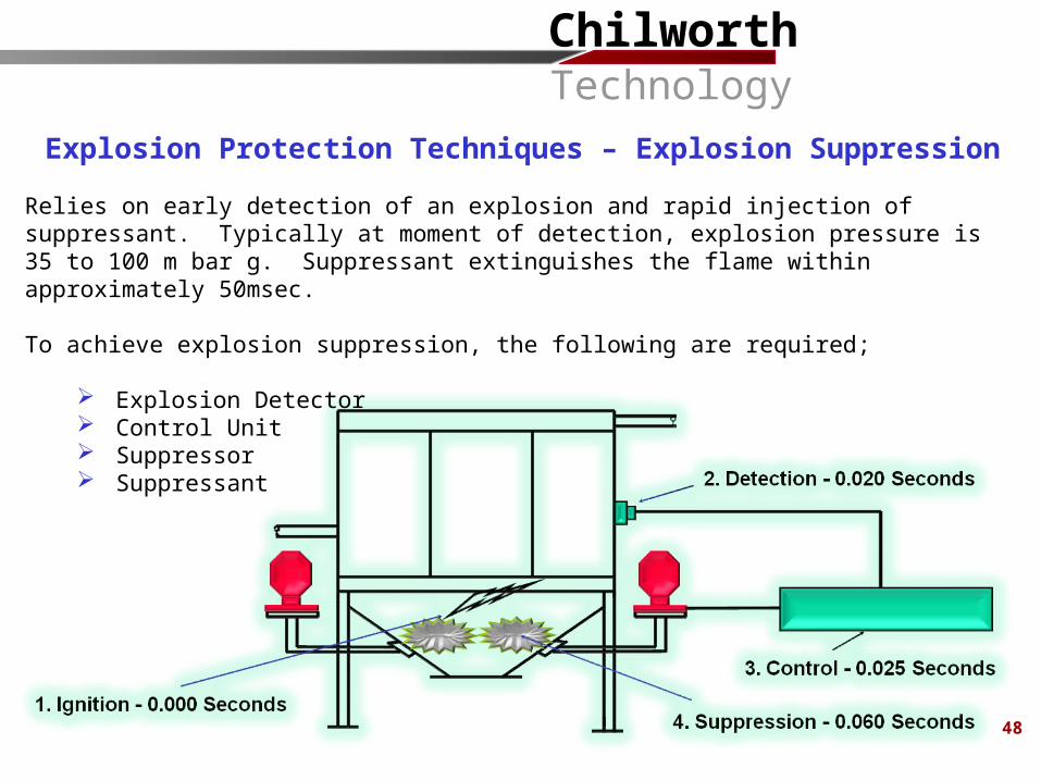
Explosion Protection Techniques – Explosion Suppression
Relies on early detection of an explosion and rapid injection of suppressant. Typically at moment of detection, explosion pressure is 35 to 100 m bar g. Suppressant extinguishes the flame within approximately 50msec. To achieve explosion suppression, the following are required;
Explosion Detector Control Unit Suppressor Suppressant
48
ChilworthTechnology
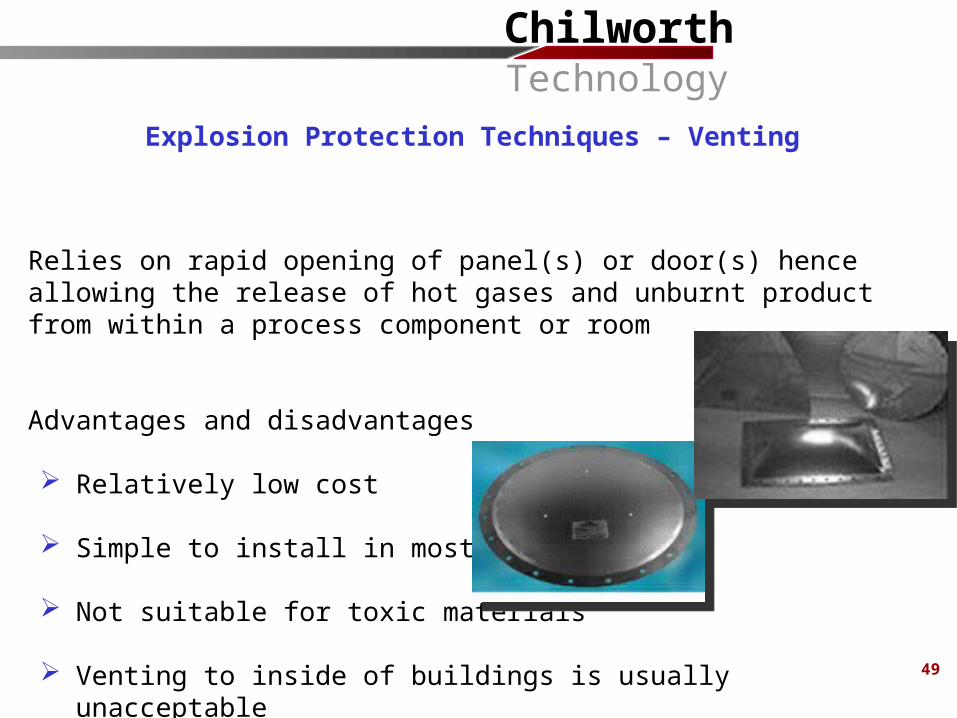
Relies on rapid opening of panel(s) or door(s) hence allowing the release of hot gases and unburnt product from within a process component or room
Advantages and disadvantages
Relatively low cost
Simple to install in most cases
Not suitable for toxic materials
Venting to inside of buildings is usually unacceptable
Explosion Protection Techniques – Venting
49
ChilworthTechnology
An explosion, initiated in one plant item should be prevented from propagating along pipes, chutes, conveyors etc. and starting a subsequent explosion in other plant items.
The simplest isolation method is avoidance of unnecessary connections. If this is not possible, special measures should be taken to create barriers to avoid propagation of an explosion.
– Mechanical Isolation (Barriers)
– Chemical Isolation (Barriers)
Explosion Protection Techniques - Isolation
50
ChilworthTechnology
An explosion (or fire) can be prevented by reducing the oxidant concentration below a level that will no longer support combustion through the addition of an inert gas to the vessel where the flammable/combustible atmosphere exists.
There are 3 commonly used inerting techniques:
Pressure PurgingVessel is pressurized with an inert gas, then relieved to the outside. This
procedure is repeated until the desired oxygen concentration is reached.
Vacuum PurgingVessel is evacuated and then pressure is increased to atmospheric using an
inert gas.
Flow-Through PurgingVessel is purged with a continuous flow of inert gas.
Inert Gas Blanketing Techniques - NFPA 69
53
ChilworthTechnology
54
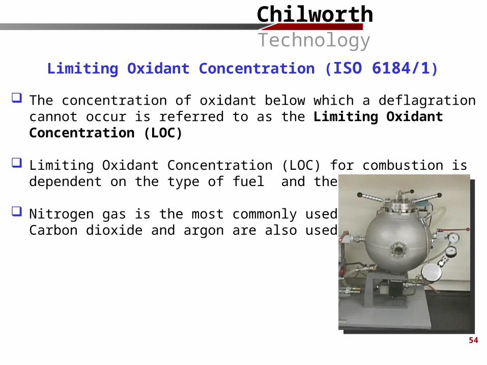
Limiting Oxidant Concentration (ISO 6184/1)
The concentration of oxidant below which a deflagration cannot occur is referred to as the Limiting Oxidant Concentration (LOC)
Limiting Oxidant Concentration (LOC) for combustion is dependent on the type of fuel and the inert gas used
Nitrogen gas is the most commonly used inert gas. Carbon dioxide and argon are also used
ChilworthTechnology
5858
Dust Explosion Hazard Assessment and ControlAn Overview
Vahid Ebadat, Ph.D.
Chilworth Technology, Inc.
250 Plainsboro Road, Building 7Plainsboro, NJ 08536TEL: 609 799 4449FAX: 609 799 5559
email: [email protected]://www.chilworth.com
Presentation at American Industrial Hygiene Conference & Exposition - Pharmaceutical Forum
June 3rd, 2009, Toronto, Canada

ChilworthTechnology
59
About Chilworth Technology
ChilworthTechnology
Chilworth Technology was first established in the UK in 1986 Since then we have expanded and are now providing process safety and
flammability services through our facilities in: United Kingdom – Chilworth Technology Ltd United States of America:
– Chilworth Technology, Inc – New Jersey
– Safety Consulting Engineers - Chicago
– Chilworth Pacific Fire Laboratories – Kelso, Washington Italy – Chilworth Vassallo Srl France – Chilworth SARL India – Chilworth Safety and Risk Management Ltd Spain – Chilworth Amalthea SL
Chilworth Technology, Inc.Our History
60
ChilworthTechnology
61
We provide services to business and industry to help identify, characterize, prevent, and mitigate potential fire, explosion, and thermal instability (runaway reaction) hazards in their processes
We achieve this by providing the following services:
Process safety consulting and Incident Investigation Laboratory testing Training courses
Chilworth Technology, Inc.Our Business
ChilworthTechnology
62
Consulting Hazard Assessment Incident Investigation Process Safety Engineering
In-Company Training Courses Gas/Vapor Explosion Hazards Dust Explosion Prevention & Protection Understanding & Controlling Static Electricity Understanding Thermal Instability Hazards
Laboratory Testing (ISO 17025 Certified Tests) Gas/Vapor Flammability Dust Fire/Explosion Electrostatic Characteristics Reaction hazards and Thermal Runaway
Chilworth Technology, Inc.Our Services
ChilworthTechnology
63
Gas & Vapor Flammability Dust Explosion Hazards Chemical Reaction Hazards Chemical Process Optimization Spontaneous Combustion and Thermal Instability Electrostatic Hazards, Problems, & Applications Hazardous (Electrical) Area Classification Transportation of Dangerous Goods Process Safety Management Flammability of Materials
Chilworth Technology, Inc.Our Expertise

ChilworthTechnology
64
Basic and Specialty Chemicals Oil and Gas Pharmaceuticals Metals Paints and Coatings Soaps and Detergents Petrochemicals Fragrance and Flavors Agrochemicals Plastics and Resins Agricultural and Food Products
Chilworth Technology serves clients in a wide variety of industries, including:
Chilworth Technology, Inc.Our Clients

ChilworthTechnology
65
Dust Explosion Hazard Assessment and ControlAn Overview
Vahid Ebadat, Ph.D.
Chilworth Technology, Inc.
250 Plainsboro Road, Building 7Plainsboro, NJ 08536TEL: 609 799 4449FAX: 609 799 5559
email: [email protected]://www.chilworth.com
Presentation at American Industrial Hygiene Conference & Exposition - Pharmaceutical Forum
June 3rd, 2009, Toronto, Canada