Embed Size (px)
Citation preview
2004 Microchip Technology Inc. DS70094C
dsPIC®
LANGUAGE TOOLS
GETTING STARTED
Note the following details of the code protection feature on Microchip devices:
• Microchip products meet the specification contained in their particular Microchip Data Sheet.
• Microchip believes that its family of products is one of the most secure families of its kind on the market today, when used in the
intended manner and under normal conditions.
• There are dishonest and possibly illegal methods used to breach the code protection feature. All of these methods, to our
knowledge, require using the Microchip products in a manner outside the operating specifications contained in Microchip’s Data
Sheets. Most likely, the person doing so is engaged in theft of intellectual property.
• Microchip is willing to work with the customer who is concerned about the integrity of their code.
• Neither Microchip nor any other semiconductor manufacturer can guarantee the security of their code. Code protection does not
mean that we are guaranteeing the product as “unbreakable.”
Code protection is constantly evolving. We at Microchip are committed to continuously improving the code protection features of our
products. Attempts to break Microchip’s code protection feature may be a violation of the Digital Millennium Copyright Act. If such acts
allow unauthorized access to your software or other copyrighted work, you may have a right to sue for relief under that Act.
Information contained in this publication regarding device
applications and the like is provided only for your convenience
and may be superseded by updates. It is your responsibility to
ensure that your application meets with your specifications.
MICROCHIP MAKES NO REPRESENTATIONS OR WAR-
RANTIES OF ANY KIND WHETHER EXPRESS OR IMPLIED,
WRITTEN OR ORAL, STATUTORY OR OTHERWISE,
RELATED TO THE INFORMATION, INCLUDING BUT NOT
LIMITED TO ITS CONDITION, QUALITY, PERFORMANCE,
MERCHANTABILITY OR FITNESS FOR PURPOSE.
Microchip disclaims all liability arising from this information and
its use. Use of Microchip’s products as critical components in
life support systems is not authorized except with express
written approval by Microchip. No licenses are conveyed,
implicitly or otherwise, under any Microchip intellectual property
rights.
DS70094C-page ii
Trademarks
The Microchip name and logo, the Microchip logo, Accuron,
dsPIC, KEELOQ, microID, MPLAB, PIC, PICmicro, PICSTART,
PRO MATE, PowerSmart, rfPIC, and SmartShunt are
registered trademarks of Microchip Technology Incorporated
in the U.S.A. and other countries.
AmpLab, FilterLab, MXDEV, MXLAB, PICMASTER, SEEVAL,
SmartSensor and The Embedded Control Solutions Company
are registered trademarks of Microchip Technology
Incorporated in the U.S.A.
Analog-for-the-Digital Age, Application Maestro, dsPICDEM,
dsPICDEM.net, dsPICworks, ECAN, ECONOMONITOR,
FanSense, FlexROM, fuzzyLAB, In-Circuit Serial
Programming, ICSP, ICEPIC, Migratable Memory, MPASM,
MPLIB, MPLINK, MPSIM, PICkit, PICDEM, PICDEM.net,
PICLAB, PICtail, PowerCal, PowerInfo, PowerMate,
PowerTool, rfLAB, rfPICDEM, Select Mode, Smart Serial,
SmartTel and Total Endurance are trademarks of Microchip
Technology Incorporated in the U.S.A. and other countries.
SQTP is a service mark of Microchip Technology Incorporated
in the U.S.A.
All other trademarks mentioned herein are property of their
respective companies.
© 2004, Microchip Technology Incorporated, Printed in the
U.S.A., All Rights Reserved.
Printed on recycled paper.
2004 Microchip Technology Inc.
Microchip received ISO/TS-16949:2002 quality system certification for its worldwide headquarters, design and wafer fabrication facilities in Chandler and Tempe, Arizona and Mountain View, California in October 2003. The Company’s quality system processes and procedures are for its PICmicro® 8-bit MCUs, KEELOQ® code hopping devices, Serial EEPROMs, microperipherals, nonvolatile memory and analog products. In addition, Microchip’s quality system for the design and manufacture of development systems is ISO 9001:2000 certified.
dsPIC® LANGUAGE TOOLS
GETTING STARTED
Table of Contents
Preface ........................................................................................................................... 1
Chapter 1. Installation and Overview
1.1 Introduction ..................................................................................................... 7
1.2 Installing MPLAB ASM30, MPLAB LINK30 and Language Tool Utilities ....... 7
1.3 Installing MPLAB C30 .................................................................................... 7
1.4 Uninstalling MPLAB C30 ................................................................................ 7
1.5 Tutorial Overview ........................................................................................... 8
Chapter 2. Tutorial 1 - Creating A Project
2.1 Introduction ..................................................................................................... 9
2.2 Creating a File ................................................................................................ 9
2.3 Using the Project Wizard .............................................................................. 10
2.4 Using the Project Window ............................................................................ 13
2.5 Setting Up Build Options .............................................................................. 14
2.6 Building the Project ...................................................................................... 18
2.7 Troubleshooting Build Errors ........................................................................ 18
2.8 Debugging with the MPLAB SIM Simulator .................................................. 20
2.9 Generating a Map File .................................................................................. 23
2.10 Debugging at Assembly Code Level .......................................................... 24
2.11 Exploring Further ........................................................................................ 26
Chapter 3. Tutorial 2 - Real-Time Interrupt
3.1 Introduction ................................................................................................... 27
3.2 Using Template Files .................................................................................... 27
3.3 Using the Template in a New Project ........................................................... 31
3.4 Debugging with the MPLAB SIM Simulator .................................................. 37
3.5 Exploring Further .......................................................................................... 41
Chapter 4. Tutorial 3 - Mixed C and Assembly Files
4.1 Introduction ................................................................................................... 43
4.2 Getting Project Source Files ......................................................................... 43
4.3 Creating and Building the Project ................................................................. 45
4.4 Examining the Program ................................................................................ 46
4.5 Exploring Further .......................................................................................... 50
4.6 Where to Go from Here ................................................................................ 50
Index ............................................................................................................................. 51
Worldwide Sales and Service .................................................................................... 54
2004 Microchip Technology Inc. DS70094C-page iii

dsPIC® Language Tools Getting Started
NOTES:
DS70094C-page iv 2004 Microchip Technology Inc.
dsPIC® LANGUAGE TOOLS
GETTING STARTEDPreface
INTRODUCTION
This chapter contains general information that will be useful to know before using the
dsPIC Language Tools. Items discussed in this chapter include:
• About This Guide
• Recommended Reading
• The Microchip Web Site
• Development Systems Customer Change Notification Service
• Customer Support
ABOUT THIS GUIDE
Document Layout
This document describes how to use dsPIC® Language Tools as development tools to
emulate and debug firmware on a target board. The manual layout is as follows:
• Chapter 1: Installation and Overview – How to install the dsPIC language tools
on your PC and how they work.
• Chapter 2: Tutorial 1 – Creating a Project – How to set up a project using dsPIC
tools.
• Chapter 3: Tutorial 2 – Real-Time Interrupt – How to create a dsPIC application
using a real-time interrupt.
• Chapter 4: Tutorial 3 – Mixed C and Assembly Files – How to create a dsPIC
application using a combination of C and assembly code files.
NOTICE TO CUSTOMERS
All documentation becomes dated, and this manual is no exception. Microchip tools
and documentation are constantly evolving to meet customer needs, so some actual
dialogs and/or tool descriptions may differ from those in this document. Please refer
to our web site (www.microchip.com) to obtain the latest documentation available.
Documents are identified with a “DS” number. This number is located on the bottom
of each page, in front of the page number. The numbering convention for the DS
number is “DSXXXXXA”, where “XXXXX” is the document number and “A” is the
revision level of the document.
For the most up-to-date information on development tools, see the MPLAB® IDE
on-line help. Select the Help menu, and then Topics to open a list of available on-line
help files.
2004 Microchip Technology Inc. DS70094C-page 1
dsPIC® Language Tools Getting Started
Conventions Used in this Guide
This manual uses the following documentation conventions:
DOCUMENTATION CONVENTIONS
Description Represents Examples
Arial font:
Italic characters Referenced books MPLAB® IDE User’s Guide
Emphasized text ...is the only compiler...
Initial caps A window the Output window
A dialog the Settings dialog
A menu selection select Enable Programmer
Quotes A field name in a window or
dialog
“Save project before build”
Underlined, italic text with
right angle bracket
A menu path File>Save
Bold characters A dialog button Click OK
A tab Click the Power tab
‘bnnnn A binary number where n is a
digit
‘b00100, ‘b10
Text in angle brackets < > A key on the keyboard Press <Enter>, <F1>
Courier font:
Plain Courier Sample source code #define START
Filenames autoexec.bat
File paths c:\mcc18\h
Keywords _asm, _endasm, static
Command-line options -Opa+, -Opa-
Bit values 0, 1
Italic Courier A variable argument file.o, where file can be
any valid filename
0xnnnn A hexadecimal number where
n is a hexadecimal digit
0xFFFF, 0x007A
Square brackets [ ] Optional arguments mcc18 [options] file [options]
Curly brackets and pipe
character: { | }
Choice of mutually exclusive
arguments; an OR selection
errorlevel {0|1}
Ellipses... Replaces repeated text var_name [, var_name...]
Represents code supplied by
user
void main (void){ ...}
DS70094C-page 2 2004 Microchip Technology Inc.
Preface
RECOMMENDED READING
This user's guide describes how to use dsPIC Language Tools. Other useful
documents are listed below. The following Microchip documents are available and
recommended as supplemental reference resources.
README Files
For the latest information on Microchip tools, read the associated README files (ASCII
text files) included with the software.
MPLAB® ASM30, MPLAB LINK30 and Utilities User's Guide (DS51317)
A guide to using the dsPIC DSC assembler, MPLAB ASM30, dsPIC DSC linker,
MPLAB LINK30 and various dsPIC DSC utilities, including MPLAB LIB30
archiver/librarian.
MPLAB® C30 C Compiler User’s Guide (DS51284)
A guide to using the dsPIC DSC C compiler. MPLAB LINK30 is used with this tool.
dsPIC® Language Tools Libraries (DS51456)
DSP, dsPIC peripheral and standard (including math) libraries, as well as MPLAB C30
built-in functions, for use with dsPIC language tools.
GNU HTML Documentation
This documentation is provided on the language tool CD-ROM. It describes the
standard GNU development tools, upon which MPLAB C30 is based.
dsPIC30F Data Sheet General Purpose and Sensor Families (DS70083)
Data sheet for dsPIC30F digital signal controller (DSC). Gives an overview of the
device and its architecture. Details memory organization, DSP operation and
peripheral functionality. Includes electrical characteristics.
dsPIC30F Family Reference Manual (DS70046)
Family reference guide explains the operation of the dsPIC30F MCU family
architecture and peripheral modules.
dsPIC30F Programmer’s Reference Manual (DS70030)
Programmer’s guide to dsPIC30F devices. Includes the programmer’s model and
instruction set.
C Standards Information
American National Standard for Information Systems – Programming Language – C.
American National Standards Institute (ANSI), 11 West 42nd. Street, New York,
New York, 10036.
This standard specifies the form and establishes the interpretation of programs
expressed in the programming language C. Its purpose is to promote portability,
reliability, maintainability and efficient execution of C language programs on a
variety of computing systems.
2004 Microchip Technology Inc. DS70094C-page 3
dsPIC® Language Tools Getting Started
C Reference Manuals
Harbison, Samuel P., and Steele, Guy L., C A Reference Manual, Fourth Edition,
Prentice-Hall, Englewood Cliffs, N.J. 07632.
Kernighan, Brian W., and Ritchie, Dennis M., The C Programming Language, Second
Edition. Prentice Hall, Englewood Cliffs, N.J. 07632.
Kochan, Steven G., Programming In ANSI C, Revised Edition. Hayden Books,
Indianapolis, Indiana 46268.
Plauger, P.J., The Standard C Library, Prentice-Hall, Englewood Cliffs, N.J. 07632.
Van Sickle, Ted., Programming Microcontrollers in C, First Edition. LLH Technology
Publishing, Eagle Rock, Virginia 24085.
THE MICROCHIP WEB SITE
Microchip provides online support via our WWW site at www.microchip.com. This web
site is used as a means to make files and information easily available to customers.
Accessible by using your favorite Internet browser, the web site contains the following
information:
• Product Support – Data sheets and errata, application notes and sample
programs, design resources, user’s guides and hardware support documents,
latest software releases and archived software
• General Technical Support – Frequently Asked Questions (FAQ), technical
support requests, online discussion groups, Microchip consultant program
member listing
• Business of Microchip – Product selector and ordering guides, latest Microchip
press releases, listing of seminars and events, listings of Microchip sales offices,
distributors and factory representatives
DEVELOPMENT SYSTEMS CUSTOMER CHANGE NOTIFICATION SERVICE
Microchip’s customer notification service helps keep customers current on Microchip
products. Subscribers will receive e-mail notification whenever there are changes,
updates, revisions or errata related to a specified product family or development tool of
interest.
To register, access the Microchip web site at www.microchip.com, click on Customer
Change Notification and follow the registration instructions.
The Development Systems product group categories are:
• Compilers – The latest information on Microchip C compilers and other language
tools. These include the MPLAB C17, MPLAB C18 and MPLAB C30 C compilers;
MPASM™ and MPLAB ASM30 assemblers; MPLINK™ and MPLAB LINK30
object linkers; and MPLIB™ and MPLAB LIB30 object librarians.
• Emulators – The latest information on Microchip in-circuit emulators.This
includes the MPLAB ICE 2000 and MPLAB ICE 4000.
• In-Circuit Debuggers – The latest information on the Microchip in-circuit
debugger, MPLAB ICD 2.
• MPLAB IDE – The latest information on Microchip MPLAB IDE, the Windows®
Integrated Development Environment for development systems tools. This list is
focused on the MPLAB IDE, MPLAB SIM simulator, MPLAB IDE Project Manager
and general editing and debugging features.
• Programmers – The latest information on Microchip programmers. These include
the MPLAB PM3 and PRO MATE® II device programmers and the PICSTART®
Plus development programmer.
DS70094C-page 4 2004 Microchip Technology Inc.
Preface
CUSTOMER SUPPORT
Users of Microchip products can receive assistance through several channels:
• Distributor or Representative
• Local Sales Office
• Field Application Engineer (FAE)
• Technical Support
• Development Systems Information Line
Customers should contact their distributor, representative or field application engineer
(FAE) for support. Local sales offices are also available to help customers. A listing of
sales offices and locations is included in the back of this document.
Technical support is available through the web site at: http://support.microchip.com
In addition, there is a Development Systems Information Line which lists the latest
versions of Microchip's development systems software products. This line also
provides information on how customers can receive currently available upgrade kits.
The Development Systems Information Line numbers are:
1-800-755-2345 – United States and most of Canada
1-480-792-7302 – Other International Locations
2004 Microchip Technology Inc. DS70094C-page 5
dsPIC® Language Tools Getting Started
NOTES:
DS70094C-page 6 2004 Microchip Technology Inc.
dsPIC® LANGUAGE TOOLS
GETTING STARTED
Chapter 1. Installation and Overview
1.1 INTRODUCTION
This document is intended to help use dsPIC30F software tools by providing a
step-by-step guide to using MPLAB® C30 with the MPLAB Integrated Development
Environment (IDE) v6.30 or later. MPLAB IDE should already be installed on the PC.
MPLAB IDE is provided on CD-ROM and is available from www.microchip.com at no
charge. The project manager for MPLAB IDE and the MPLAB SIM simulator are both
components of MPLAB IDE and, along with the built-in debugger, will be used
extensively in this guide.
Items discussed in this chapter are:
• Installing MPLAB ASM30, MPLAB LINK30 and Language Tool Utilities
• Installing MPLAB C30
• Uninstalling MPLAB C30
• Tutorial Overview
1.2 INSTALLING MPLAB ASM30, MPLAB LINK30 AND LANGUAGE TOOL UTILITIES
MPLAB ASM30 and MPLAB LINK30 are provided free with MPLAB IDE. They are also
included in the MPLAB C30 compiler installation. To ensure compatibility between all
dsPIC30F tools, the versions of these tools provided with MPLAB C30 compiler should
be used.
1.3 INSTALLING MPLAB C30
• When installing MPLAB C30 compiler as an update to a previous version, it may
overwrite existing files on the PC. A backup should be made to retain files which
may have been modified.
• Insert the CD-ROM into the PC and execute the installation MPLAB C30 vX.XX
(where X.XX is the current version number) file. A series of dialogs will step
through the installation process. The installation may take a few minutes as it
searches for MPLAB IDE and other related files on the PC.
• To follow the examples in this guide, make sure that the check box for
EXAMPLES is checked.
1.4 UNINSTALLING MPLAB C30
To uninstall MPLAB C30, open the folder where the compiler is installed and
double-click on UNWISE.EXE.
Note: When uninstalling an upgraded version of MPLAB C30, the entire
installation will be removed. If files have been added to directories after the
previous installation, these will not be removed.
2004 Microchip Technology Inc. DS70094C-page 7
dsPIC® Language Tools Getting Started
1.5 TUTORIAL OVERVIEW
The following tutorials are intended to help an engineer familiar with the
C programming language and embedded systems concepts get started using the
MPLAB C30 compiler with MPLAB Integrated Development Environment (IDE). This
document shows how to create and build projects, how to write code using features of
dsPIC30F devices and how to verify and debug code written with MPLAB C30.
These tutorials assume that the MPLAB C30 compiler and MPLAB IDE v6.30 (or later)
are installed. Please refer to the dsPIC® literature, such as the dsPIC30F Data Sheet
General Purpose and Sensor Families (DS70083) and dsPIC30F Programmer’s
Reference Manual (DS70030) for information regarding processor-specific items such
as the special function registers, instruction set and interrupt logic.
Tutorials presented in these chapters for using the MPLAB C30 compiler include:
• Chapter 2 which demonstrates how to:
- set up and build a project
- run, step and set breakpoints in the example code
- debug the code.
• Chapter 3 which demonstrates how to:
- use templates to create a source file
- use a real-time interrupt in C
• Chapter 4 which demonstrates how to:
- use MPLAB C30 compiler with an assembly language DSP routine
- pass parameters to and from an assembly language module
DS70094C-page 8 2004 Microchip Technology Inc.
dsPIC® LANGUAGE TOOLS
GETTING STARTED
Chapter 2. Tutorial 1 - Creating A Project
2.1 INTRODUCTION
The simple source code in this tutorial is designed for an MPLAB IDE v6.xx project. It
will use the MPLAB SIM simulator for the dsPIC30F6014 device. The tutorial assumes
that the directory c:\pic30_tools is the MPLAB C30 compiler installation directory.
This tutorial consists of:
• Creating a File
• Using the Project Wizard
• Using the Project Window
• Setting Up Build Options
• Building the Project
• Troubleshooting Build Errors
• Debugging with the MPLAB SIM Simulator
• Generating a Map File
• Debugging at Assembly Code Level
• Exploring Further
2.2 CREATING A FILE
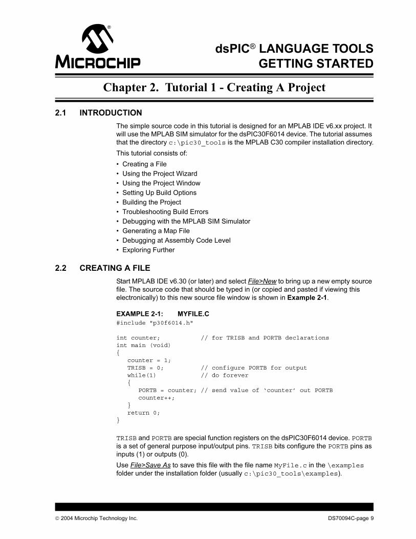
Start MPLAB IDE v6.30 (or later) and select File>New to bring up a new empty source
file. The source code that should be typed in (or copied and pasted if viewing this
electronically) to this new source file window is shown in Example 2-1.
EXAMPLE 2-1: MYFILE.C
#include "p30f6014.h"
int counter; // for TRISB and PORTB declarationsint main (void){ counter = 1; TRISB = 0; // configure PORTB for output while(1) // do forever { PORTB = counter; // send value of ‘counter’ out PORTB counter++; } return 0;}
TRISB and PORTB are special function registers on the dsPIC30F6014 device. PORTB
is a set of general purpose input/output pins. TRISB bits configure the PORTB pins as
inputs (1) or outputs (0).
Use File>Save As to save this file with the file name MyFile.c in the \examples
folder under the installation folder (usually c:\pic30_tools\examples).
2004 Microchip Technology Inc. DS70094C-page 9
dsPIC® Language Tools Getting Started
2.3 USING THE PROJECT WIZARD
Select Project>Project Wizard to create a new project. The Welcome page will appear.
Click Next> to continue.
1. At “Step One: Select a Device”, use the pull-down menu to select the
dsPIC30F6014 device. Click Next> to continue.
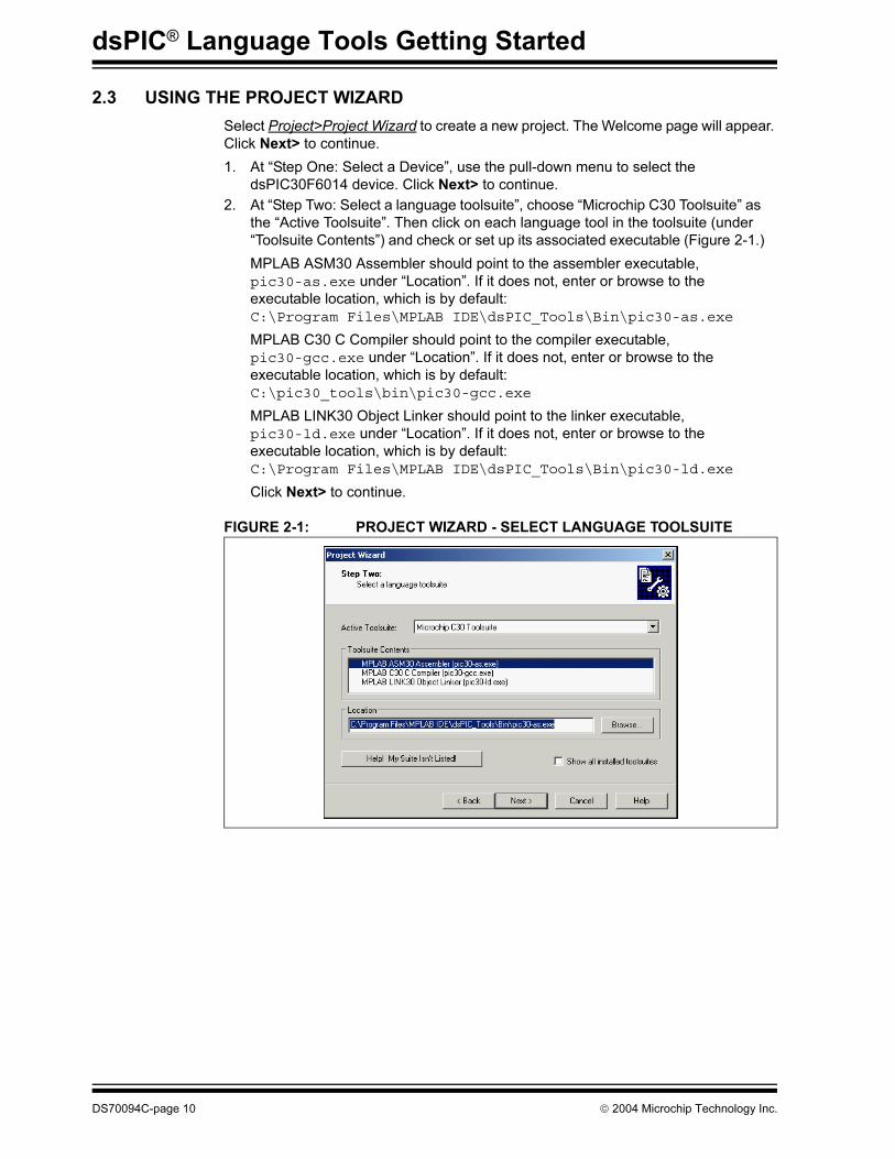
2. At “Step Two: Select a language toolsuite”, choose “Microchip C30 Toolsuite” as
the “Active Toolsuite”. Then click on each language tool in the toolsuite (under
“Toolsuite Contents”) and check or set up its associated executable (Figure 2-1.)
MPLAB ASM30 Assembler should point to the assembler executable,
pic30-as.exe under “Location”. If it does not, enter or browse to the
executable location, which is by default:
C:\Program Files\MPLAB IDE\dsPIC_Tools\Bin\pic30-as.exe
MPLAB C30 C Compiler should point to the compiler executable,
pic30-gcc.exe under “Location”. If it does not, enter or browse to the
executable location, which is by default:
C:\pic30_tools\bin\pic30-gcc.exe
MPLAB LINK30 Object Linker should point to the linker executable,
pic30-ld.exe under “Location”. If it does not, enter or browse to the
executable location, which is by default:
C:\Program Files\MPLAB IDE\dsPIC_Tools\Bin\pic30-ld.exe
Click Next> to continue.
FIGURE 2-1: PROJECT WIZARD - SELECT LANGUAGE TOOLSUITE
DS70094C-page 10 2004 Microchip Technology Inc.
Tutorial 1 - Creating A Project
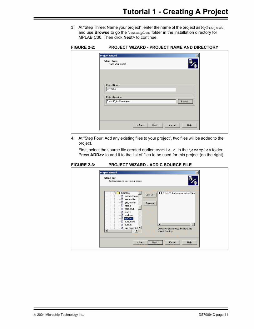
3. At “Step Three: Name your project”, enter the name of the project as MyProject
and use Browse to go the \examples folder in the installation directory for
MPLAB C30. Then click Next> to continue.
FIGURE 2-2: PROJECT WIZARD - PROJECT NAME AND DIRECTORY
4. At “Step Four: Add any existing files to your project”, two files will be added to the
project.
First, select the source file created earlier, MyFile.c, in the \examples folder.
Press ADD>> to add it to the list of files to be used for this project (on the right).
FIGURE 2-3: PROJECT WIZARD - ADD C SOURCE FILE
2004 Microchip Technology Inc. DS70094C-page 11
dsPIC® Language Tools Getting Started
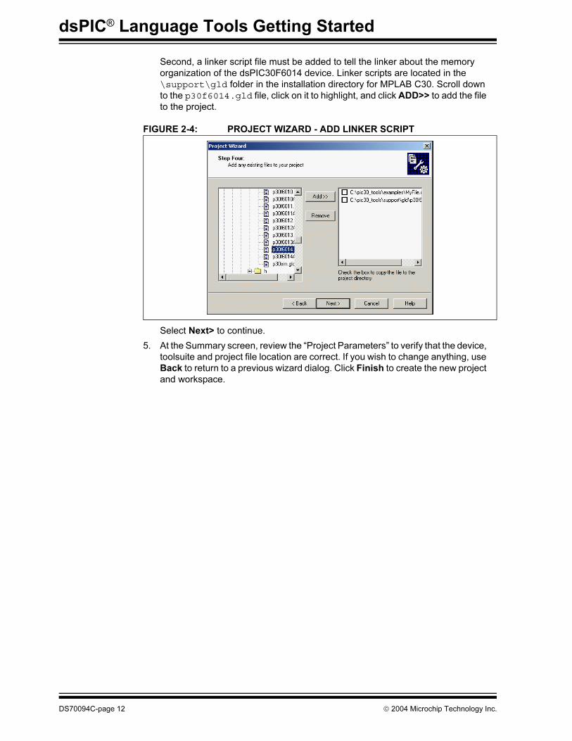
Second, a linker script file must be added to tell the linker about the memory
organization of the dsPIC30F6014 device. Linker scripts are located in the
\support\gld folder in the installation directory for MPLAB C30. Scroll down
to the p30f6014.gld file, click on it to highlight, and click ADD>> to add the file
to the project.
FIGURE 2-4: PROJECT WIZARD - ADD LINKER SCRIPT
Select Next> to continue.
5. At the Summary screen, review the “Project Parameters” to verify that the device,
toolsuite and project file location are correct. If you wish to change anything, use
Back to return to a previous wizard dialog. Click Finish to create the new project
and workspace.
DS70094C-page 12 2004 Microchip Technology Inc.
Tutorial 1 - Creating A Project
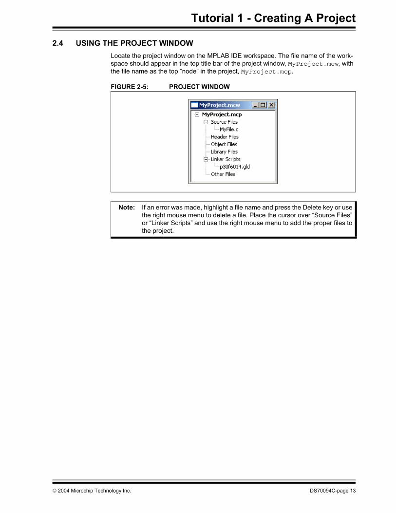
2.4 USING THE PROJECT WINDOW
Locate the project window on the MPLAB IDE workspace. The file name of the work-
space should appear in the top title bar of the project window, MyProject.mcw, with
the file name as the top “node” in the project, MyProject.mcp.
FIGURE 2-5: PROJECT WINDOW
Note: If an error was made, highlight a file name and press the Delete key or use
the right mouse menu to delete a file. Place the cursor over “Source Files”
or “Linker Scripts” and use the right mouse menu to add the proper files to
the project.
2004 Microchip Technology Inc. DS70094C-page 13
dsPIC® Language Tools Getting Started
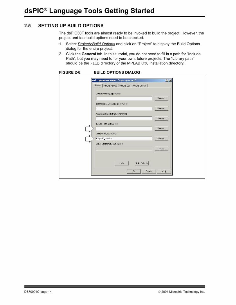
2.5 SETTING UP BUILD OPTIONS
The dsPIC30F tools are almost ready to be invoked to build the project. However, the
project and tool build options need to be checked.
1. Select Project>Build Options and click on “Project” to display the Build Options
dialog for the entire project.
2. Click the General tab. In this tutorial, you do not need to fill in a path for “Include
Path”, but you may need to for your own, future projects. The “Library path”
should be the \lib directory of the MPLAB C30 installation directory.
FIGURE 2-6: BUILD OPTIONS DIALOG
DS70094C-page 14 2004 Microchip Technology Inc.
Tutorial 1 - Creating A Project
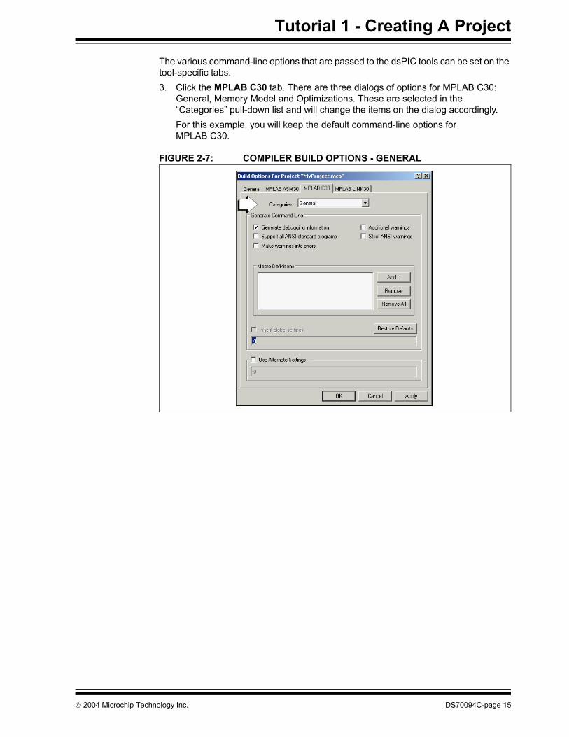
The various command-line options that are passed to the dsPIC tools can be set on the
tool-specific tabs.
3. Click the MPLAB C30 tab. There are three dialogs of options for MPLAB C30:
General, Memory Model and Optimizations. These are selected in the
“Categories” pull-down list and will change the items on the dialog accordingly.
For this example, you will keep the default command-line options for
MPLAB C30.
FIGURE 2-7: COMPILER BUILD OPTIONS - GENERAL
2004 Microchip Technology Inc. DS70094C-page 15
dsPIC® Language Tools Getting Started
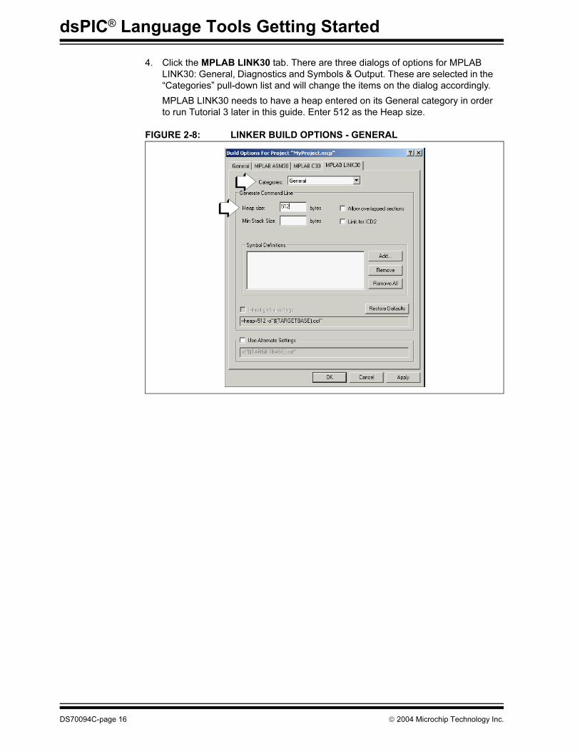
4. Click the MPLAB LINK30 tab. There are three dialogs of options for MPLAB
LINK30: General, Diagnostics and Symbols & Output. These are selected in the
“Categories” pull-down list and will change the items on the dialog accordingly.
MPLAB LINK30 needs to have a heap entered on its General category in order
to run Tutorial 3 later in this guide. Enter 512 as the Heap size.
FIGURE 2-8: LINKER BUILD OPTIONS - GENERAL
DS70094C-page 16 2004 Microchip Technology Inc.
Tutorial 1 - Creating A Project
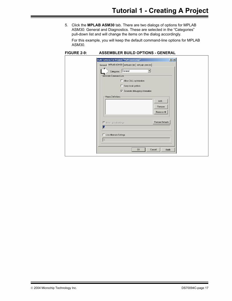
5. Click the MPLAB ASM30 tab. There are two dialogs of options for MPLAB
ASM30: General and Diagnostics. These are selected in the “Categories”
pull-down list and will change the items on the dialog accordingly.
For this example, you will keep the default command-line options for MPLAB
ASM30.
FIGURE 2-9: ASSEMBLER BUILD OPTIONS - GENERAL
2004 Microchip Technology Inc. DS70094C-page 17
dsPIC® Language Tools Getting Started
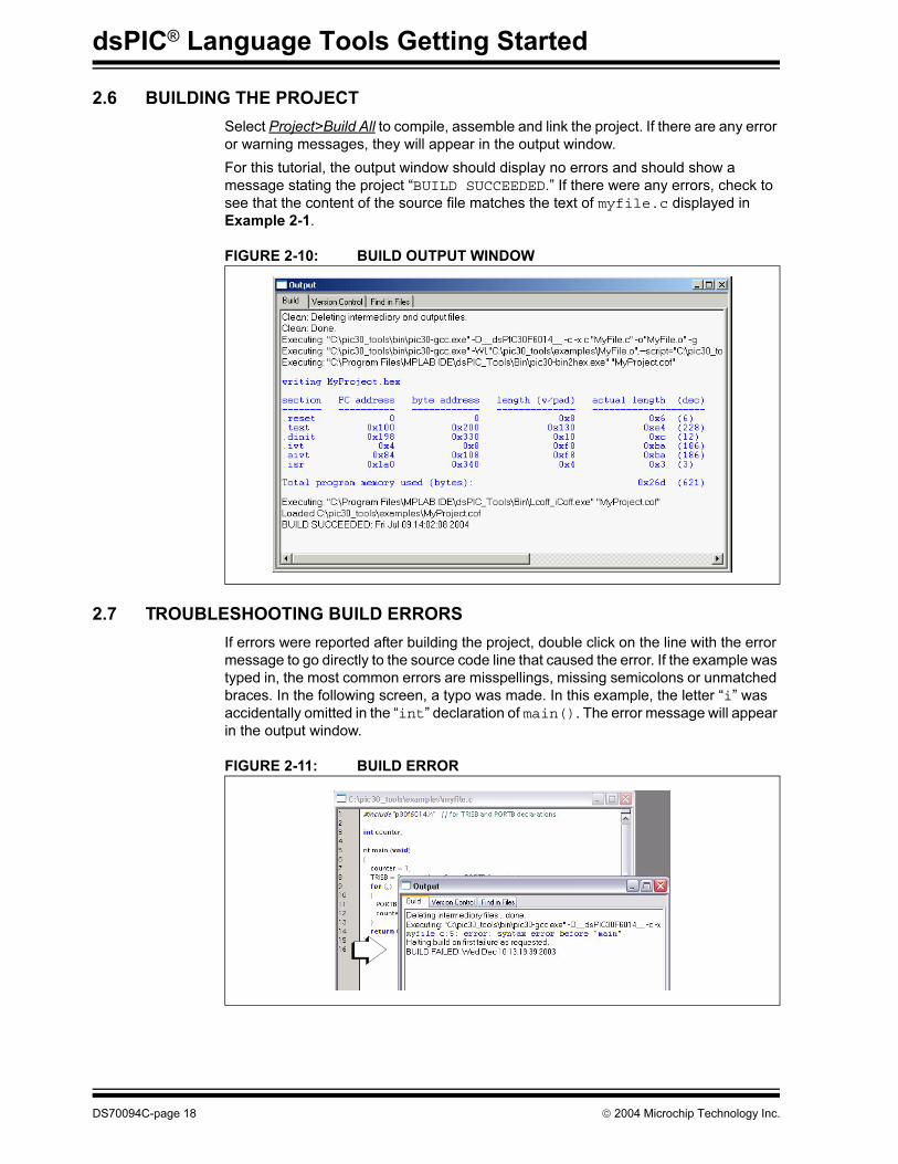
2.6 BUILDING THE PROJECT
Select Project>Build All to compile, assemble and link the project. If there are any error
or warning messages, they will appear in the output window.
For this tutorial, the output window should display no errors and should show a
message stating the project “BUILD SUCCEEDED.” If there were any errors, check to
see that the content of the source file matches the text of myfile.c displayed in
Example 2-1.
FIGURE 2-10: BUILD OUTPUT WINDOW
2.7 TROUBLESHOOTING BUILD ERRORS
If errors were reported after building the project, double click on the line with the error
message to go directly to the source code line that caused the error. If the example was
typed in, the most common errors are misspellings, missing semicolons or unmatched
braces. In the following screen, a typo was made. In this example, the letter “i” was
accidentally omitted in the “int” declaration of main(). The error message will appear
in the output window.
FIGURE 2-11: BUILD ERROR
DS70094C-page 18 2004 Microchip Technology Inc.
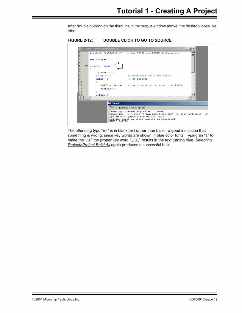
Tutorial 1 - Creating A Project
After double clicking on the third line in the output window above, the desktop looks like
this:
FIGURE 2-12: DOUBLE CLICK TO GO TO SOURCE
The offending typo “nt” is in black text rather than blue – a good indication that
something is wrong, since key words are shown in blue color fonts. Typing an “i” to
make the “nt” the proper key word “int,” results in the text turning blue. Selecting
Project>Project Build All again produces a successful build.
2004 Microchip Technology Inc. DS70094C-page 19
dsPIC® Language Tools Getting Started
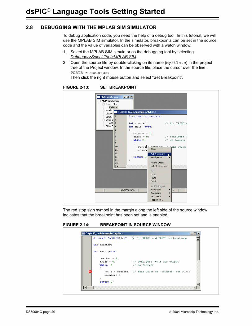
2.8 DEBUGGING WITH THE MPLAB SIM SIMULATOR
To debug application code, you need the help of a debug tool. In this tutorial, we will
use the MPLAB SIM simulator. In the simulator, breakpoints can be set in the source
code and the value of variables can be observed with a watch window.
1. Select the MPLAB SIM simulator as the debugging tool by selecting
Debugger>Select Tool>MPLAB SIM.
2. Open the source file by double-clicking on its name (MyFile.c) in the project
tree of the Project window. In the source file, place the cursor over the line:
PORTB = counter;Then click the right mouse button and select “Set Breakpoint”.
FIGURE 2-13: SET BREAKPOINT
The red stop sign symbol in the margin along the left side of the source window
indicates that the breakpoint has been set and is enabled.
FIGURE 2-14: BREAKPOINT IN SOURCE WINDOW
DS70094C-page 20 2004 Microchip Technology Inc.
Tutorial 1 - Creating A Project
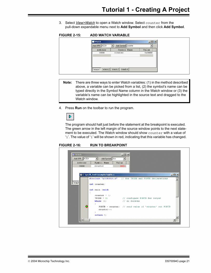
3. Select View>Watch to open a Watch window. Select counter from the
pull-down expandable menu next to Add Symbol and then click Add Symbol.
FIGURE 2-15: ADD WATCH VARIABLE
4. Press Run on the toolbar to run the program.
The program should halt just before the statement at the breakpoint is executed.
The green arrow in the left margin of the source window points to the next state-
ment to be executed. The Watch window should show counter with a value of
‘1’. The value of ‘1’ will be shown in red, indicating that this variable has changed.
FIGURE 2-16: RUN TO BREAKPOINT
Note: There are three ways to enter Watch variables: (1) in the method described
above, a variable can be picked from a list, (2) the symbol’s name can be
typed directly in the Symbol Name column in the Watch window or (3) the
variable’s name can be highlighted in the source text and dragged to the
Watch window.
2004 Microchip Technology Inc. DS70094C-page 21
dsPIC® Language Tools Getting Started
5. Press Run again to continue the program. Execution will continue in the while
loop until it halts again at the line with the breakpoint. The Watch window should
show counter with a value of ‘2’.
6. To step through the source code one statement at a time, use Step Into on the
toolbar.
As each statement executes, the green arrow in the margin of the source window
moves to the next statement to be executed.
7. Place the cursor on the line with the breakpoint, and use the right mouse button
menu to select “Remove Breakpoint”. Now press the Run button. The “Run-
ning...” message should appear on the lower left of the Status bar, and next to it,
a moving bar will indicate that the program is running. The Step icon to the right
of the Run Icon will be grayed out. If the Debugger menu is pulled down, the Step
options will also be grayed out. While in the Run mode, these operations are
disabled.
To interrupt a running program, use Halt on the toolbar.
Once the program has stopped (halted), the step icons are no longer grayed out.
Note: There are two basic modes while debugging: Halt or Run. Most debugging
operations are done in Halt mode. In Run mode, most debug functions are
not operational. Registers cannot be inspected or changed and a project
cannot be rebuilt. Functions that try to access the memory or internal reg-
isters of the running target will not be available in Run mode.
DS70094C-page 22 2004 Microchip Technology Inc.
Tutorial 1 - Creating A Project
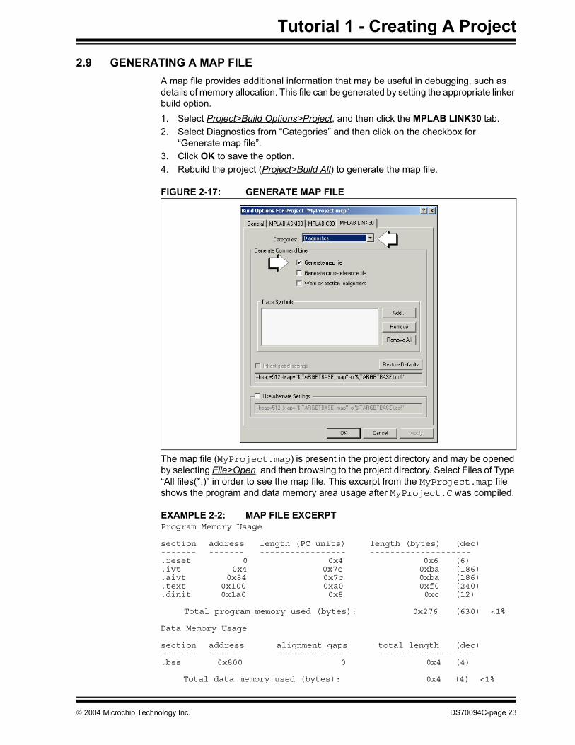
2.9 GENERATING A MAP FILE
A map file provides additional information that may be useful in debugging, such as
details of memory allocation. This file can be generated by setting the appropriate linker
build option.
1. Select Project>Build Options>Project, and then click the MPLAB LINK30 tab.
2. Select Diagnostics from “Categories” and then click on the checkbox for
“Generate map file”.
3. Click OK to save the option.
4. Rebuild the project (Project>Build All) to generate the map file.
FIGURE 2-17: GENERATE MAP FILE
The map file (MyProject.map) is present in the project directory and may be opened
by selecting File>Open, and then browsing to the project directory. Select Files of Type
“All files(*.)” in order to see the map file. This excerpt from the MyProject.map file
shows the program and data memory area usage after MyProject.C was compiled.
EXAMPLE 2-2: MAP FILE EXCERPTProgram Memory Usage
section address length (PC units) length (bytes) (dec)------- ------- ----------------- --------------------.reset 0 0x4 0x6 (6).ivt 0x4 0x7c 0xba (186).aivt 0x84 0x7c 0xba (186).text 0x100 0xa0 0xf0 (240).dinit 0x1a0 0x8 0xc (12)
Total program memory used (bytes): 0x276 (630) <1%
Data Memory Usage
section address alignment gaps total length (dec)------- ------- -------------- -------------------.bss 0x800 0 0x4 (4)
Total data memory used (bytes): 0x4 (4) <1%
2004 Microchip Technology Inc. DS70094C-page 23
dsPIC® Language Tools Getting Started
2.10 DEBUGGING AT ASSEMBLY CODE LEVEL
So far all debugging has been done from the C source file, using functions and
variables as defined in the C code. For embedded systems programming, it may be
necessary to dig down deeper into the assembly code level. MPLAB IDE provides tools
to do both, and shows the correlation between the C code and the generated machine
code.
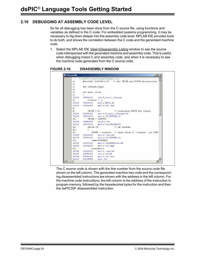
1. Select the MPLAB IDE View>Disassembly Listing window to see the source
code interspersed with the generated machine and assembly code. This is useful
when debugging mixed C and assembly code, and when it is necessary to see
the machine code generated from the C source code.
FIGURE 2-18: DISASSEMBLY WINDOW
The C source code is shown with the line number from the source code file
shown on the left column. The generated machine hex code and the correspond-
ing disassembled instructions are shown with the address in the left column. For
the machine code instructions, the left column is the address of the instruction in
program memory, followed by the hexadecimal bytes for the instruction and then
the dsPIC30F disassembled instruction.
DS70094C-page 24 2004 Microchip Technology Inc.
Tutorial 1 - Creating A Project
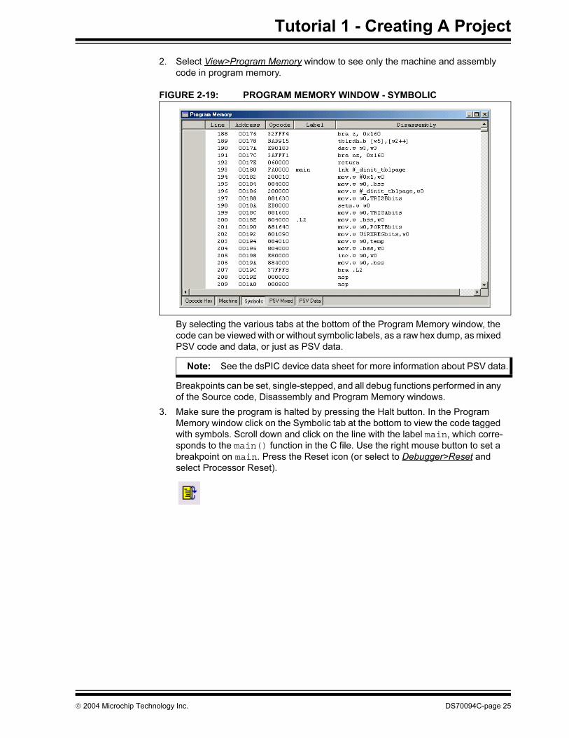
2. Select View>Program Memory window to see only the machine and assembly
code in program memory.
FIGURE 2-19: PROGRAM MEMORY WINDOW - SYMBOLIC
By selecting the various tabs at the bottom of the Program Memory window, the
code can be viewed with or without symbolic labels, as a raw hex dump, as mixed
PSV code and data, or just as PSV data.
Breakpoints can be set, single-stepped, and all debug functions performed in any
of the Source code, Disassembly and Program Memory windows.
3. Make sure the program is halted by pressing the Halt button. In the Program
Memory window click on the Symbolic tab at the bottom to view the code tagged
with symbols. Scroll down and click on the line with the label main, which corre-
sponds to the main() function in the C file. Use the right mouse button to set a
breakpoint on main. Press the Reset icon (or select to Debugger>Reset and
select Processor Reset).
Note: See the dsPIC device data sheet for more information about PSV data.
2004 Microchip Technology Inc. DS70094C-page 25
dsPIC® Language Tools Getting Started
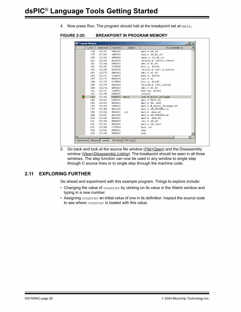
4. Now press Run. The program should halt at the breakpoint set at main.
FIGURE 2-20: BREAKPOINT IN PROGRAM MEMORY
5. Go back and look at the source file window (File>Open) and the Disassembly
window (View>Disassembly Listing). The breakpoint should be seen in all three
windows. The step function can now be used in any window to single step
through C source lines or to single step through the machine code.
2.11 EXPLORING FURTHER
Go ahead and experiment with this example program. Things to explore include:
• Changing the value of counter by clicking on its value in the Watch window and
typing in a new number.
• Assigning counter an initial value of one in its definition. Inspect the source code
to see where counter is loaded with this value.
DS70094C-page 26 2004 Microchip Technology Inc.
dsPIC® LANGUAGE TOOLS
GETTING STARTED
Chapter 3. Tutorial 2 - Real-Time Interrupt
3.1 INTRODUCTION
This next tutorial demonstrates real-time interrupt code implemented using the basic
“template” file that comes with MPLAB® IDE software. Timer 1 on the dsPIC30F6104
will be used to generate a recurring interrupt to measure one-second intervals.
This tutorial consists of:
• Using Template Files
• Using the Template in a New Project
• Debugging with the MPLAB SIM Simulator
• Exploring Further
3.2 USING TEMPLATE FILES
Template files are source code files that can serve as a structure to build an application.
They make it easy to start a project for an application since the C constructs and
formats are provided in a simple file where details of an application can be added. The
templates have example C statements for many common features of MPLAB C30
source code, including variables and constants, processor-specific include files,
interrupt vectors and associated interrupt code, plus areas to insert application code.
The template has comments to help identify key constructs. In many cases macros are
defined to make some things easier. In the simplest form, here is a “stripped-down”
template without these comments and macros so its basic structure can be seen:
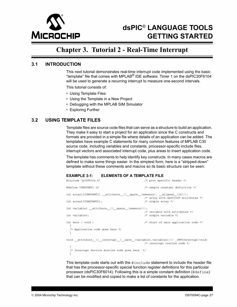
EXAMPLE 3-1: ELEMENTS OF A TEMPLATE FILE#include "p30F6014.h" /* proc specific header */
#define CONSTANT1 10 /* sample constant definition */
int array1[CONSTANT1] __attribute__((__space__(xmemory), __aligned__(32))); /* array with dsPIC30F attributes */int array5[CONSTANT2]; /* simple array */
int variable1 __attribute__((__space__(xmemory))); /* variable with attributes */int variable3; /* simple variable */
int main ( void ) /* start of main application code */ { /* Application code goes here */ }
void __attribute__((__interrupt__(__save__(variable1,variable2)))) _INT0Interrupt(void) /* interrupt routine code */ { /* Interrupt Service Routine code goes here */ }
This template code starts out with the #include statement to include the header file
that has the processor-specific special function register definitions for this particular
processor (dsPIC30F6014). Following this is a simple constant definition (#define)
that can be modified and copied to make a list of constants for the application.
2004 Microchip Technology Inc. DS70094C-page 27
dsPIC® Language Tools Getting Started
Two array definitions follow to show how to define an array with various attributes,
specifying its section in memory, and how it is aligned in the memory architecture of the
dsPIC device. The second array definition, array5, is a simple array.
Like arrays, variables can be assigned with attributes (variable1), or with no
attributes (variable3).
A code fragment for main() follows. This is where code for the application can be
placed. Following main() is the code framework for an interrupt.
Actual applications may use different interrupts, different attributes, and will be more
complicated than this, but this template provides a simple place to start. Along with the
appropriate linker file, the unmodified template can be added to a new project, and the
project will build with no errors.
Templates are stored in a folder with the dsPIC tools installation directory named
\support\templates, and are provided for both assembler and compiler source
files in the corresponding \asm and \c folders.
Here is the full source code for the C template file for the dsPIC30F6014:
EXAMPLE 3-2: TEMP_6014.C TEMPLATE FILE/*********************************************************************** * This file is a basic template for creating C code for a dsPIC30F * * device. Copy this file into your project directory and modify or * * add to it as needed. * * Add the suitable linker script (e.g., p30f6014.gld) to the project. * * * * If interrupts are not used, all code presented for that interrupt * * can be removed or commented out with C-style comment declarations. * * * * For additional information about dsPIC architecture and language * * tools, refer to the following documents: * * * * MPLAB C30 Compiler User's Guide : C30.pdf * * MPLAB C30 Compiler Reference Guide : R30.pdf * * dsPIC 30F Assembler, Linker and Utilities User's Guide : ALU.pdf * * dsPIC 30F 16-bit MCU Family Reference Manual : DS70046 * * dsPIC 30F Sensor and General Purpose Family Data Sheet : DS70083 * * dsPIC 30F Programmer's Reference Manual : DS70030 * * * * Template file has been compiled with MPLAB C30 V 1.3. * * * *********************************************************************** * * * Author: * * Company: * * Filename: temp_6014.c * * Date: 08/20/2004 * * File Version: 1.30 * * Other Files Required: p30F6014.gld, libpic30.a * * Tools Used: MPLAB GL -> 6.60 * * Compiler -> 1.30 * * Assembler -> 1.30 * * Linker -> 1.30 * * * * Devices Supported: * * dsPIC30F2011 * * dsPIC30F3012 * * dsPIC30F2012 * * dsPIC30F3013 * * dsPIC30F3014 * * dsPIC30F5011 * * dsPIC30F6011 * * dsPIC30F6012 * * dsPIC30F5013 * * dsPIC30F6013 * * dsPIC30F6014 * * * ***********************************************************************
DS70094C-page 28 2004 Microchip Technology Inc.
Tutorial 2 - Real-Time Interrupt
*********************************************************************** * * * Other Comments: * * * * 1) C attributes, designated by the __attribute__ keyword, provide a * * means to specify various characteristics of a variable or * * function, such as where a particular variable should be placed * * in memory, whether the variable should be aligned to a certain * * address boundary, whether a function is an Interrupt Service * * Routine (ISR), etc. If no special characteristics need to be * * specified for a variable or function, then attributes are not * * required. For more information about attributes, refer to the * * C30 User's Guide. * * * * 2) The __space__(xmemory) and __space__(ymemory) attributes * * are used to place a variable in X data space and Y data space, * * respectively. Variables accessed by dual-source DSP instructions * * must be defined using these attributes. * * * * 3) The aligned(k) attribute, used in variable definitions, is used * * to align a variable to the nearest higher 'k'-byte address * * boundary. 'k' must be substituted with a suitable constant * * number when the ModBuf_X(k) or ModBuf_Y(k) macro is invoked. * * In most cases, variables are aligned either to avoid potential * * misaligned memory accesses, or to configure a modulo buffer. * * * * 4) The __interrupt__ attribute is used to qualify a function as an * * interrupt service routine. An interrupt routine can be further * * configured to save certain variables on the stack, using the * * __save__(var-list) directive. * * * * 5) The __shadow__ attribute is used to set up any function to * * perform a fast context save using shadow registers. * * * * 6) Note the use of double-underscores (__) at the start and end of * * all the keywords mentioned above. * * * **********************************************************************/
/* Include the appropriate header (.h) file, depending on device used *//* Replace the path shown here with the header path in your system *//* Example (for dsPIC30F5013): #include "Your_path\p30F5013.h" */
/* Alternatively, the header file may be inserted from the Project *//* window in the MPLAB IDE */
#include "p30F6014.h"
/* Define constants here */
#define CONSTANT1 10#define CONSTANT2 20
/* Define macros to simplify attribute declarations */
#define ModBuf_X(k) __attribute__((__space__(xmemory), __aligned__(k)))#define ModBuf_Y(k) __attribute__((__space__(ymemory), __aligned__(k)))
/************* START OF GLOBAL DEFINITIONS **********/
/* Define arrays: array1[], array2[], etc. *//* with attributes, as given below */
/* either using the entire attribute */int array1[CONSTANT1] __attribute__((__space__(xmemory), __aligned__(32)));int array2[CONSTANT1] __attribute__((__space__(ymemory), __aligned__(32)));
/* or using macros defined above */int array3[CONSTANT1] ModBuf_X(32);int array4[CONSTANT1] ModBuf_Y(32);
2004 Microchip Technology Inc. DS70094C-page 29
dsPIC® Language Tools Getting Started
/* Define arrays without attributes */
int array5[CONSTANT2]; /* array5 is NOT an aligned buffer */
/* ------------------------------------------------ */
/* Define global variables with attributes */
int variable1 __attribute__((__space__(xmemory)));int variable2 __attribute__((__space__(ymemory)));
/* Define global variables without attributes */
int variable3;
/************** END OF GLOBAL DEFINITIONS ***********/
/************* START OF MAIN FUNCTION ***************/
int main ( void ){
/* Code goes here */
}/****** START OF INTERRUPT SERVICE ROUTINES *********/
/* Replace the interrupt function names with the *//* appropriate names depending on interrupt source. */
/* The names of various interrupt functions for *//* each device are defined in the linker script. */
/* Interrupt Service Routine 1 *//* No fast context save, and no variables stacked */
void __attribute__((__interrupt__)) _ADCInterrupt(void){
/* Interrupt Service Routine code goes here */ }
/* Interrupt Service Routine 2 *//* Fast context save (using push.s and pop.s) */
void __attribute__((__interrupt__, __shadow__)) _T1Interrupt(void){
/* Interrupt Service Routine code goes here */ }
/* Interrupt Service Routine 3: INT0Interrupt *//* Save and restore variables var1, var2, etc. */
void __attribute__((__interrupt__(__save__(variable1,variable2)))) _INT0Interrupt(void){
/* Interrupt Service Routine code goes here */
}
/********* END OF INTERRUPT SERVICE ROUTINES ********/
DS70094C-page 30 2004 Microchip Technology Inc.
Tutorial 2 - Real-Time Interrupt
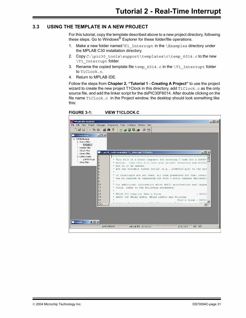
3.3 USING THE TEMPLATE IN A NEW PROJECT
For this tutorial, copy the template described above to a new project directory, following
these steps. Go to Windows® Explorer for these folder/file operations.
1. Make a new folder named \T1_Interrupt in the \Examples directory under
the MPLAB C30 installation directory.
2. Copy C:\pic30_tools\support\templates\c\temp_6014.c to the new
\T1_Interrupt folder.
3. Rename the copied template file temp_6014.c in the \T1_Interrupt folder
to T1Clock.c.
4. Return to MPLAB IDE.
Follow the steps from Chapter 2. “Tutorial 1 - Creating A Project” to use the project
wizard to create the new project T1Clock in this directory, add T1Clock.c as the only
source file, and add the linker script for the dsPIC30F6014. After double clicking on the
file name T1Clock.c in the Project window, the desktop should look something like
this:
FIGURE 3-1: VIEW T1CLOCK.C
2004 Microchip Technology Inc. DS70094C-page 31
dsPIC® Language Tools Getting Started
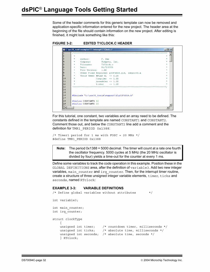
Some of the header comments for this generic template can now be removed and
application-specific information entered for the new project. The header area at the
beginning of the file should contain information on the new project. After editing is
finished, it might look something like this:
FIGURE 3-2: EDITED T1CLOCK.C HEADER
For this tutorial, one constant, two variables and an array need to be defined. The
constants defined in the template are named CONSTANT1 and CONSTANT2.
Comment those out, and below the CONSTANT2 line add a comment and the
definition for TMR1_PERIOD 0x1388:
/* Timer1 period for 1 ms with FOSC = 20 MHz */#define TMR1_PERIOD 0x1388
Define some variables to track the code operation in this example. Position these in the
GLOBAL DEFINITIONS area, after the definition of variable3. Add two new integer
variables, main_counter and irq_counter. Then, for the interrupt timer routine,
create a structure of three unsigned integer variable elements, timer, ticks and
seconds, named RTclock:
EXAMPLE 3-3: VARIABLE DEFINITIONS
/* Define global variables without attributes */
int variable3;
int main_counter;int irq_counter;
struct clockType { unsigned int timer; /* countdown timer, milliseconds */ unsigned int ticks; /* absolute time, milliseconds */ unsigned int seconds; /* absolute time, seconds */ } RTclock;
Note: The period 0x1388 = 5000 decimal. The timer will count at a rate one fourth
the oscillator frequency. 5000 cycles at 5 MHz (the 20 MHz oscillator is
divided by four) yields a time-out for the counter at every 1 ms.
DS70094C-page 32 2004 Microchip Technology Inc.
Tutorial 2 - Real-Time Interrupt
The other template code in this tutorial can be left in or commented out. It is probably
better to comment it out at this time since these definitions will get compiled and take
up memory space. Make sure to comment out all the sample arrays, since they use the
macros which can be commented out. Also, as the code grows, it may be difficult to
remember which code is used by the application and which was part of the original
template.
After the section labelled END OF GLOBAL DEFINITIONS type in this routine to
initialize Timer 1 as an interrupt timer using the internal clock (the bolded text is the
code that should be typed in):
EXAMPLE 3-4: RESET_CLOCK CODE/************** END OF GLOBAL DEFINITIONS ***********/
void reset_clock(void) { RTclock.timer = 0; /* clear software registers */ RTclock.ticks = 0; RTclock.seconds = 0; TMR1 = 0; /* clear timer1 register */ PR1 = TMR1_PERIOD; /* set period1 register */ T1CONbits.TCS = 0; /* set internal clock source */ IPC0bits.T1IP = 4; /* set priority level */ IFS0bits.T1IF = 0; /* clear interrupt flag */ IEC0bits.T1IE = 1; /* enable interrupts */ SRbits.IPL = 3; /* enable CPU priority levels 4-7 */ T1CONbits.TON = 1; /* start the timer */ }
/************* START OF MAIN FUNCTION ***************/
This routine uses special function register names, such as TMR1 and T1CONbits.TCS
that are defined in the header file p30F6014.h. Refer to the data sheet for more
information on these control bits and registers for Timer 1.
A main routine and an interrupt service routine may need to be written. The most
complex routine is the interrupt service routine. It is executed when Timer 1 counts
down 0x1388 cycles. It increments a counter sticks at each of these 1 ms interrupt
until it exceeds one thousand. Then it increments the seconds variable in the
RTclock structure and resets sticks. This routine should count time in seconds. In
the section labelled “START OF INTERRUPT SERVICE ROUTINES” where a template
for the _T1Interrupt() code is written, replace the comment
“/* Interrupt Service Routine code goes here */”
with these lines of code (added code is bold):
Note: When using the template, remember that when beginning to code the
application, only a few elements of the template may be needed. It may be
helpful to comment out those portions of code that are not being used so
that later, when similar elements are needed, they can be referred back to
as models.
2004 Microchip Technology Inc. DS70094C-page 33
dsPIC® Language Tools Getting Started
EXAMPLE 3-5: INTERRUPT SERVICE ROUTINE/* Interrupt Service Routine 2 *//* Fast context save (using push.s and pop.s) */
void __attribute__((__interrupt__, __shadow__)) _T1Interrupt(void) { static int sticks=0; irq_counter++; if (RTclock.timer > 0) /* if timer is active */ RTclock.timer -= 1; /* decrement it */ RTclock.ticks++; /* increment ticks counter */ if (sticks++ == 1000) { /* if time to rollover */ sticks = 0; /* clear seconds ticks */ RTclock.seconds++; /* and increment seconds */ } IFS0bits.T1IF = 0; /* clear interrupt flag */ }
/* Interrupt Service Routine 3: INT0Interrupt *//* Save and restore variables var1, var2, etc. */
There are three sample interrupt functions in the template file. Comment out
_INT0Interrupt() because it uses two of the template file sample variables and, as
a result, will not compile. _ADCInterrupt() can be commented out too, since it will
not be used in this tutorial.
By comparison to the Timer 1 interrupt code, the main() code is simple. Type this in
for the body, replacing the line “/* code goes here */” (added code is bold):
EXAMPLE 3-6: MAIN CODE/************* START OF MAIN FUNCTION ***************/
int main ( void ) { reset_clock();
for (;;) main_counter++; }
/****** START OF INTERRUPT SERVICE ROUTINES *********/
The main() code is simply a call to our Timer 1 initialization routine, followed by an
infinite loop, allowing the Timer 1 interrupt to function. Typically, an application that
made use of this timer would be placed in this loop in place of this test variable,
main_counter.
DS70094C-page 34 2004 Microchip Technology Inc.
Tutorial 2 - Real-Time Interrupt
The final code should now look like this:
EXAMPLE 3-7: FINAL C CODE FILE/*********************************************************************** * * * Author: F. Bar * * Company: Widgets, Inc. * * Filename: T1Clock.c * * Date: 08/20/2004 * * File Version: 1.30 * * Other Files Required: p30F6014.gld, libpic30.a * * Tools Used: MPLAB GL -> 6.60 * * Compiler -> 1.30 * * Assembler -> 1.30 * * Linker -> 1.30 ************************************************************************/
#include "c:\pic30_tools\support\h\p30F6014.h"
/* Define constants here *//* #define CONSTANT1 10 #define CONSTANT2 20 *//* Timer1 period for 1 ms with FOSC = 20 MHz */#define TMR1_PERIOD 0x1388
/* Define macros to simplify attribute declarations */
#define ModBuf_X(k) __attribute__((__space__(xmemory), __aligned__(k)))#define ModBuf_Y(k) __attribute__((__space__(ymemory), __aligned__(k)))
/************* START OF GLOBAL DEFINITIONS **********//* Define arrays: array1[], array2[], etc. *//* with attributes, as given below */
/* either using the entire attribute *//* int array1[CONSTANT1] __attribute__((__space__(xmemory), __aligned__(32))); int array2[CONSTANT1] __attribute__((__space__(ymemory), __aligned__(32)));*//* or using macros defined above *//* int array3[CONSTANT1] ModBuf_X(32); int array4[CONSTANT1] ModBuf_Y(32); *//* Define arrays without attributes *//* int array5[CONSTANT2]; */ /* array5 is NOT an aligned buffer */
/* ------------------------------------------------ */
/* Define global variables with attributes *//* int variable1 __attribute__((__space__(xmemory))); int variable2 __attribute__((__space__(ymemory)));*/
/* Define global variables without attributes *//* int variable3; */int main_counter;int irq_counter;
struct clockType { unsigned int timer; /* countdown timer, milliseconds */ unsigned int ticks; /* absolute time, milliseconds */ unsigned int seconds; /* absolute time, seconds */ } RTclock;
2004 Microchip Technology Inc. DS70094C-page 35
dsPIC® Language Tools Getting Started
/************** END OF GLOBAL DEFINITIONS ***********/
void reset_clock(void) { RTclock.timer = 0; /* clear software registers */ RTclock.ticks = 0; RTclock.seconds = 0; TMR1 = 0; /* clear timer1 register */ PR1 = TMR1_PERIOD; /* set period1 register */ T1CONbits.TCS = 0; /* set internal clock source */ IPC0bits.T1IP = 4; /* set priority level */ IFS0bits.T1IF = 0; /* clear interrupt flag */ IEC0bits.T1IE = 1; /* enable interrupts */ SRbits.IPL = 3; /* enable CPU priority levels 4-7 */ T1CONbits.TON = 1; /* start the timer */}
/************* START OF MAIN FUNCTION ***************/int main ( void ) { reset_clock();
while (1) main_counter++; }
/****** START OF INTERRUPT SERVICE ROUTINES *********//* Interrupt Service Routine 1 *//* No fast context save, and no variables stacked *//* void __attribute__((__interrupt__)) _ADCInterrupt(void)*/
/* Interrupt Service Routine 2 *//* Fast context save (using push.s and pop.s) */
void __attribute__((__interrupt__, __shadow__)) _T1Interrupt(void) { static int sticks=0;
irq_counter++;
if (RTclock.timer > 0) /* if countdown timer is active */ RTclock.timer -= 1; /* decrement it */
RTclock.ticks++; /* increment ticks counter */
if (sticks++ > 1000) { /* if time to rollover */ sticks = 0; /* clear seconds ticks */ RTclock.seconds++; /* and increment seconds */ } IFS0bits.T1IF = 0; /* clear interrupt flag */
return; }
/* Interrupt Service Routine 3: INT0Interrupt *//* Save and restore variables var1, var2, etc. *//* void __attribute__((__interrupt__(__save__(variable1)))) _INT0Interrupt(void)*/
/********* END OF INTERRUPT SERVICE ROUTINES ********/
If everything is typed correctly, then selecting Project>Build All should result in a
successful compilation. Double click on any errors appearing in the output window to
return to the source code to fix typos and rebuild the project until it builds with no errors.
DS70094C-page 36 2004 Microchip Technology Inc.
Tutorial 2 - Real-Time Interrupt
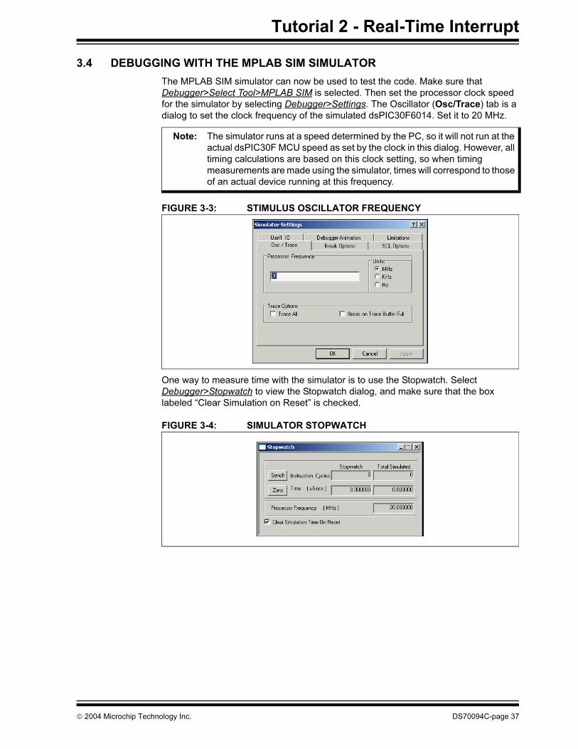
3.4 DEBUGGING WITH THE MPLAB SIM SIMULATOR
The MPLAB SIM simulator can now be used to test the code. Make sure that
Debugger>Select Tool>MPLAB SIM is selected. Then set the processor clock speed
for the simulator by selecting Debugger>Settings. The Oscillator (Osc/Trace) tab is a
dialog to set the clock frequency of the simulated dsPIC30F6014. Set it to 20 MHz.
FIGURE 3-3: STIMULUS OSCILLATOR FREQUENCY
One way to measure time with the simulator is to use the Stopwatch. Select
Debugger>Stopwatch to view the Stopwatch dialog, and make sure that the box
labeled “Clear Simulation on Reset” is checked.
FIGURE 3-4: SIMULATOR STOPWATCH
Note: The simulator runs at a speed determined by the PC, so it will not run at the
actual dsPIC30F MCU speed as set by the clock in this dialog. However, all
timing calculations are based on this clock setting, so when timing
measurements are made using the simulator, times will correspond to those
of an actual device running at this frequency.
2004 Microchip Technology Inc. DS70094C-page 37
dsPIC® Language Tools Getting Started
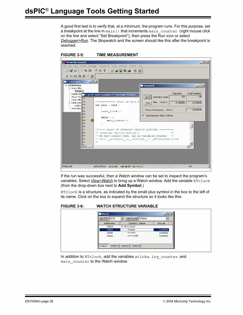
A good first test is to verify that, at a minimum, the program runs. For this purpose, set
a breakpoint at the line in main() that increments main_counter (right mouse click
on the line and select “Set Breakpoint”), then press the Run icon or select
Debugger>Run. The Stopwatch and the screen should like this after the breakpoint is
reached.
FIGURE 3-5: TIME MEASUREMENT
If the run was successful, then a Watch window can be set to inspect the program’s
variables. Select View>Watch to bring up a Watch window. Add the variable RTclock
(from the drop-down box next to Add Symbol.)
RTclock is a structure, as indicated by the small plus symbol in the box to the left of
its name. Click on the box to expand the structure so it looks like this:
FIGURE 3-6: WATCH STRUCTURE VARIABLE
In addition to RTclock, add the variables sticks, irq_counter, and
main_counter to the Watch window.
DS70094C-page 38 2004 Microchip Technology Inc.

Tutorial 2 - Real-Time Interrupt
FIGURE 3-7: ALL WATCH VARIABLES
The Value column may be expanded wider in order to read the text on the sticks
variable. You will see that it says “Out of Scope.” This means that, unlike RTclock,
irq_counter, and main_counter, this is not a global variable, and its value can only
be accessed while the function _T1Interrupt()is executing.
When inspecting the variables in the Watch window at this first breakpoint, all of them
should be equal to zero. This is to be expected, since Timer 1 just has been initialized
and counter has not yet been incremented for the first time.
Press the Step Into icon to step once around the main() loop. The value of
main_counter should now show 0001. The interrupt routine has not yet fired.
Looking at the Stopwatch window, the elapsed time only increments by a microsecond
each time through the main() loop. To reach the first interrupt, you would have to step
a thousand times (1000 x 1 us = 1 ms).
In order to test the interrupt functionality, remove the breakpoint at main_counter++
by clicking on the highlighted line with the right mouse button and select “Remove
Breakpoint”. Now select “Set Breakpoint” in the right mouse menu to put a breakpoint
in the interrupt service routine at the irq_counter++ statement. Then, press Run.
The Stopwatch should look like this:
FIGURE 3-8: STOPWATCH AT FIRST INTERRUPT
The value shown in the Time window is 1.0216 ms. This is about what was expected,
since the interrupt should happen every millisecond. There was some time since
RESET that was counted by the Stopwatch, including the C start-up code and the
Timer 1 initialization.
Note: The Address column for sticks does not have a value. This is another
indication that sticks is a local variable.
2004 Microchip Technology Inc. DS70094C-page 39
dsPIC® Language Tools Getting Started
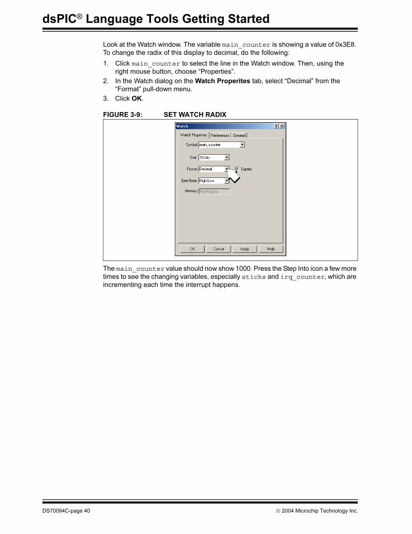
Look at the Watch window. The variable main_counter is showing a value of 0x3E8.
To change the radix of this display to decimal, do the following:
1. Click main_counter to select the line in the Watch window. Then, using the
right mouse button, choose “Properties”.
2. In the Watch dialog on the Watch Properites tab, select “Decimal” from the
“Format” pull-down menu.
3. Click OK.
FIGURE 3-9: SET WATCH RADIX
The main_counter value should now show 1000. Press the Step Into icon a few more
times to see the changing variables, especially sticks and irq_counter, which are
incrementing each time the interrupt happens.
DS70094C-page 40 2004 Microchip Technology Inc.
Tutorial 2 - Real-Time Interrupt
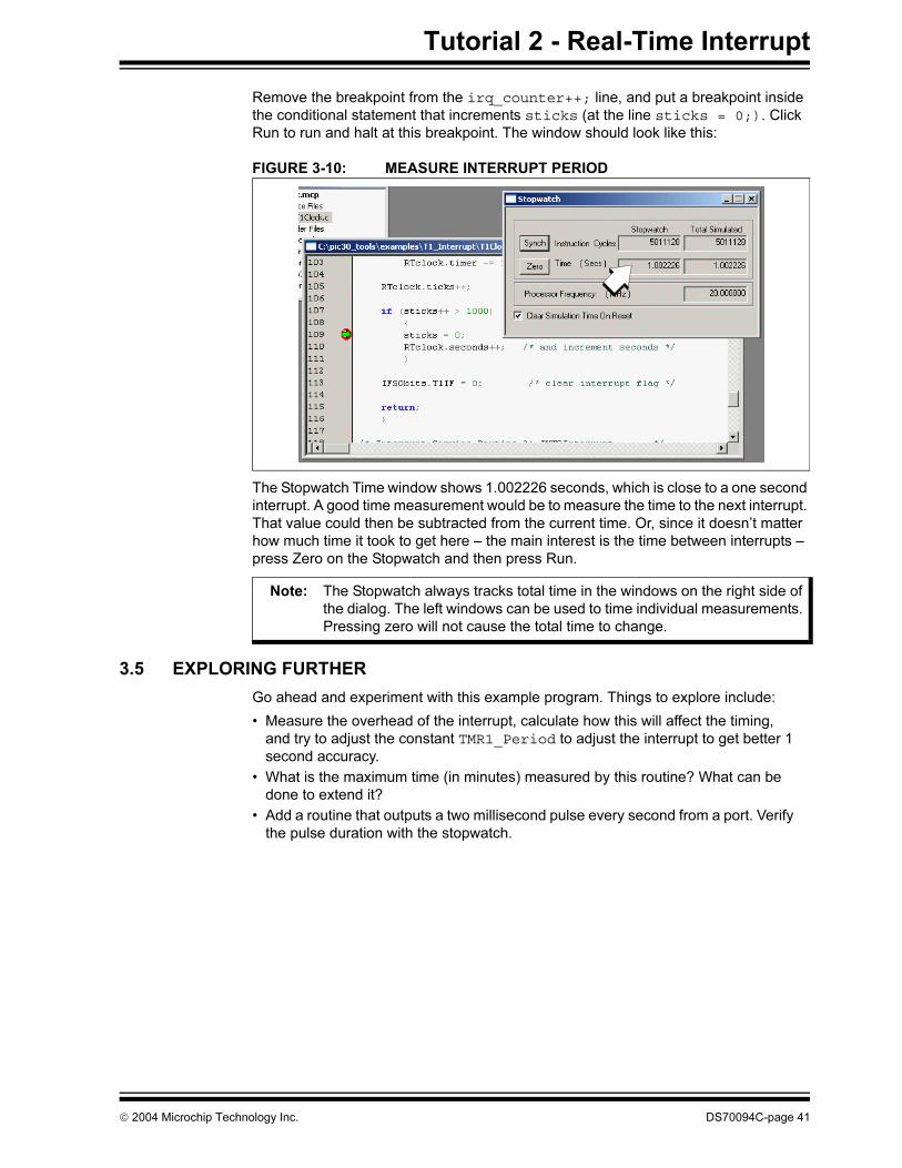
Remove the breakpoint from the irq_counter++; line, and put a breakpoint inside
the conditional statement that increments sticks (at the line sticks = 0;). Click
Run to run and halt at this breakpoint. The window should look like this:
FIGURE 3-10: MEASURE INTERRUPT PERIOD
The Stopwatch Time window shows 1.002226 seconds, which is close to a one second
interrupt. A good time measurement would be to measure the time to the next interrupt.
That value could then be subtracted from the current time. Or, since it doesn’t matter
how much time it took to get here – the main interest is the time between interrupts –
press Zero on the Stopwatch and then press Run.
3.5 EXPLORING FURTHER
Go ahead and experiment with this example program. Things to explore include:
• Measure the overhead of the interrupt, calculate how this will affect the timing,
and try to adjust the constant TMR1_Period to adjust the interrupt to get better 1
second accuracy.
• What is the maximum time (in minutes) measured by this routine? What can be
done to extend it?
• Add a routine that outputs a two millisecond pulse every second from a port. Verify
the pulse duration with the stopwatch.
Note: The Stopwatch always tracks total time in the windows on the right side of
the dialog. The left windows can be used to time individual measurements.
Pressing zero will not cause the total time to change.
2004 Microchip Technology Inc. DS70094C-page 41

dsPIC® Language Tools Getting Started
NOTES:
DS70094C-page 42 2004 Microchip Technology Inc.
dsPIC® LANGUAGE TOOLS
GETTING STARTED
Chapter 4. Tutorial 3 - Mixed C and Assembly Files
4.1 INTRODUCTION
This tutorial will show how to make a project that uses an assembly language routine
that is called from a C source file.
This tutorial consists of:
• Getting Project Source Files
• Creating and Building the Project
• Examining the Program
• Exploring Further
• Where to Go from Here
4.2 GETTING PROJECT SOURCE FILES
The files for this tutorial are available in the \Examples folder and are called
example3.c, a C source code file, and modulo.s, an assembly language file. Create
a folder in the \Examples folder called \DSP_ASM and copy these two files to that new
folder. See Chapter 3. “Tutorial 2 - Real-Time Interrupt” for how to do this.
For reference, Example 4-1and Example 4-2 show listings of these two files.
EXAMPLE 4-1: C SOURCE FILE/********************************************************************** * Filename: example3.c * * Date: 08/20/2004 * * File Version: 1.30 * * Tools used: MPLAB -> 6.60 * * Compiler -> 1.30 * * Assembler -> 1.30 * * Linker -> 1.30 * * Linker File: p30f6014.gld * ***********************************************************************/
#include "p30f6014.h"#include <stdio.h>
/* Length of output buffer (in words) */#define PRODLEN 20
/* source arrays of 16-bit elements */unsigned int array1[PRODLEN/2] __attribute__((__space__(xmemory), aligned(32)));unsigned int array2[PRODLEN/2] __attribute__((__space__(ymemory), aligned(32)));
/* output array of 32-bit products defined here */long array3[PRODLEN/2]; /* array3 is NOT a circular buffer */
/* Pointer for traversing array */unsigned int array_index;
/* 'Point-by-point array multiplication' assembly function prototype */extern void modulo( unsigned int *, unsigned int *, unsigned int *, unsigned int );
int main ( void ){ /* Set up Modulo addressing for X AGU using W8 and for Y AGU using W10 *//* Actual Modulo Mode will be turned on in the assembly language routine */
2004 Microchip Technology Inc. DS70094C-page 43
dsPIC® Language Tools Getting Started
CORCON |= 0x0001; /* Enable integer arithmetic */ XMODSRT = (unsigned int)array1; XMODEND = (unsigned int)array1 + PRODLEN - 1; YMODSRT = (unsigned int)array2; YMODEND = (unsigned int)array2 + PRODLEN - 1; /* Initialize 10-element arrays, array1 and array2 *//* to values 1, 2, ...., 10 */ while (1) /* just do this over and over */ { for (array_index = 0; array_index < PRODLEN/2; array_index++) { array1[array_index] = array1[array_index] + array_index + 1; array2[array_index] = array2[array_index] + (array_index+1) * 3; }
/* Call assembly subroutine to do point-by-point multiply *//* of array1 and array2, with 4 parameters: *//* start addresses of array1, array2 and array3, and PRODLEN-1 *//* in that order */ modulo( array1, array2, array3, PRODLEN-1 ); }}
EXAMPLE 4-2: MODULO.S ASM SOURCE FILE/********************************************************************** * Filename: modulo.s * * Date: 08/20/2004 * * File Version: 1.30 * * * * Tools used: MPLAB -> 6.60 * * Compiler -> 1.30 * * Assembler -> 1.30 * * Linker -> 1.30 * * * * Linker File: p30f6014.gld * * Description: Assembly routine used in example3.C * **********************************************************************/
.text
.global _modulo_modulo:
; If any of the registers W8 - W15 are used, they should be saved ; W0 - W7 may be used without saving PUSH W8 PUSH W10 ; turn on modulo addressing MOV #0xC0A8, W8 MOV W8, MODCON ; The 3 pointers were passed in W0, W1 and W2 when function was called ; Transfer pointers to appropriate registers for MPY MOV W0, W8 ; Initializing X pointer MOV W1, W10 ; Initializing Y pointer ; Clear Accumulator and prefetch 1st pair of numbers CLR A, [W8]+=2, W4, [W10]+=2, W7 LSR W3, W3 RCALL array_loop ; do multiply set INC2 W8, W8 ; Change alignment of X pointer RCALL array_loop ; second multiply set POP W10 POP W8 RETURN ; Return to main C program
DS70094C-page 44 2004 Microchip Technology Inc.
Tutorial 3 - Mixed C and Assembly Files
array_loop: ; Set up DO loop with count 'PRODLEN - 1' (passed in W3) DO W3, here
; Do a point-by-point multiply MPY W4*W7, A, [W8]+=2, W4, [W10]+=2, W7
; Store result in a 32-bit array pointed by W2 MOV ACCAL, W5 MOV W5, [W2++]
MOV ACCAH, W5here: MOV W5, [W2++]
; turn off modulo addressing CLR MODCON
RETURN
.end
4.3 CREATING AND BUILDING THE PROJECT
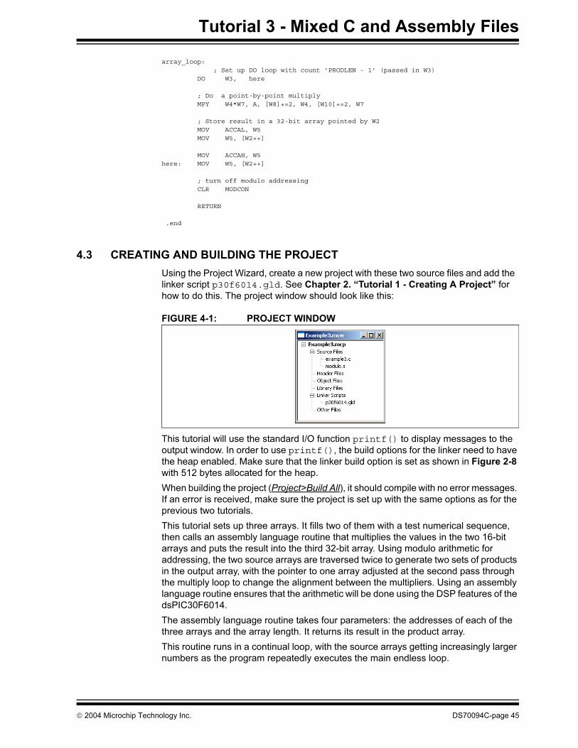
Using the Project Wizard, create a new project with these two source files and add the
linker script p30f6014.gld. See Chapter 2. “Tutorial 1 - Creating A Project” for
how to do this. The project window should look like this:
FIGURE 4-1: PROJECT WINDOW
This tutorial will use the standard I/O function printf() to display messages to the
output window. In order to use printf(), the build options for the linker need to have
the heap enabled. Make sure that the linker build option is set as shown in Figure 2-8
with 512 bytes allocated for the heap.
When building the project (Project>Build All), it should compile with no error messages.
If an error is received, make sure the project is set up with the same options as for the
previous two tutorials.
This tutorial sets up three arrays. It fills two of them with a test numerical sequence,
then calls an assembly language routine that multiplies the values in the two 16-bit
arrays and puts the result into the third 32-bit array. Using modulo arithmetic for
addressing, the two source arrays are traversed twice to generate two sets of products
in the output array, with the pointer to one array adjusted at the second pass through
the multiply loop to change the alignment between the multipliers. Using an assembly
language routine ensures that the arithmetic will be done using the DSP features of the
dsPIC30F6014.
The assembly language routine takes four parameters: the addresses of each of the
three arrays and the array length. It returns its result in the product array.
This routine runs in a continual loop, with the source arrays getting increasingly larger
numbers as the program repeatedly executes the main endless loop.
2004 Microchip Technology Inc. DS70094C-page 45
dsPIC® Language Tools Getting Started
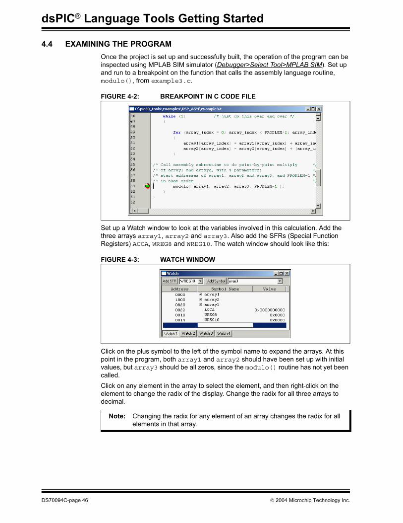
4.4 EXAMINING THE PROGRAM
Once the project is set up and successfully built, the operation of the program can be
inspected using MPLAB SIM simulator (Debugger>Select Tool>MPLAB SIM). Set up
and run to a breakpoint on the function that calls the assembly language routine,
modulo(), from example3.c.
FIGURE 4-2: BREAKPOINT IN C CODE FILE
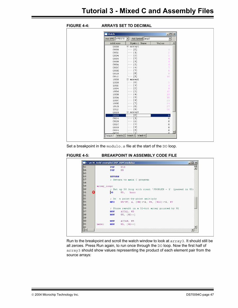
Set up a Watch window to look at the variables involved in this calculation. Add the
three arrays array1, array2 and array3. Also add the SFRs (Special Function
Registers) ACCA, WREG8 and WREG10. The watch window should look like this:
FIGURE 4-3: WATCH WINDOW
Click on the plus symbol to the left of the symbol name to expand the arrays. At this
point in the program, both array1 and array2 should have been set up with initial
values, but array3 should be all zeros, since the modulo() routine has not yet been
called.
Click on any element in the array to select the element, and then right-click on the
element to change the radix of the display. Change the radix for all three arrays to
decimal.
Note: Changing the radix for any element of an array changes the radix for all
elements in that array.
DS70094C-page 46 2004 Microchip Technology Inc.
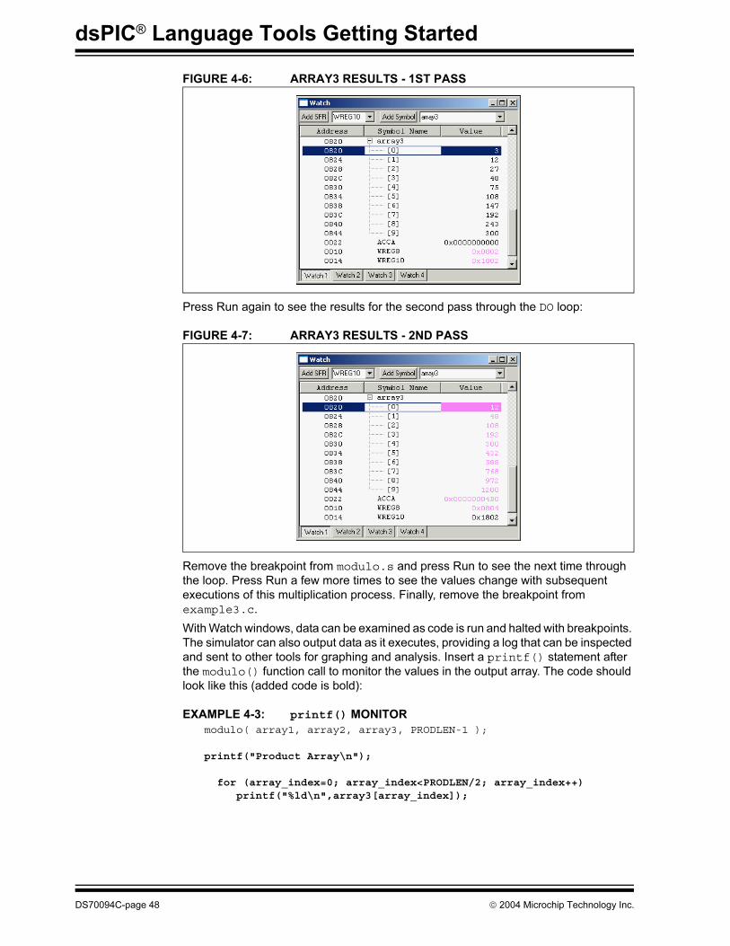
Tutorial 3 - Mixed C and Assembly Files
FIGURE 4-4: ARRAYS SET TO DECIMAL
Set a breakpoint in the modulo.s file at the start of the DO loop.
FIGURE 4-5: BREAKPOINT IN ASSEMBLY CODE FILE
Run to the breakpoint and scroll the watch window to look at array3. It should still be
all zeroes. Press Run again, to run once through the DO loop. Now the first half of
array3 should show values representing the product of each element pair from the
source arrays:
2004 Microchip Technology Inc. DS70094C-page 47
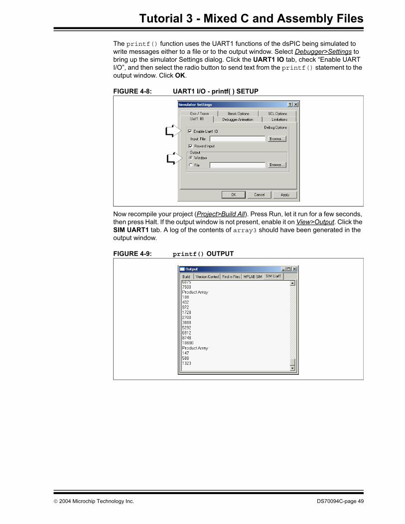
dsPIC® Language Tools Getting Started
FIGURE 4-6: ARRAY3 RESULTS - 1ST PASS
Press Run again to see the results for the second pass through the DO loop:
FIGURE 4-7: ARRAY3 RESULTS - 2ND PASS
Remove the breakpoint from modulo.s and press Run to see the next time through
the loop. Press Run a few more times to see the values change with subsequent
executions of this multiplication process. Finally, remove the breakpoint from
example3.c.
With Watch windows, data can be examined as code is run and halted with breakpoints.
The simulator can also output data as it executes, providing a log that can be inspected
and sent to other tools for graphing and analysis. Insert a printf() statement after
the modulo() function call to monitor the values in the output array. The code should
look like this (added code is bold):
EXAMPLE 4-3: printf() MONITOR
modulo( array1, array2, array3, PRODLEN-1 );
printf("Product Array\n");
for (array_index=0; array_index<PRODLEN/2; array_index++) printf("%ld\n",array3[array_index]);
DS70094C-page 48 2004 Microchip Technology Inc.
Tutorial 3 - Mixed C and Assembly Files
The printf() function uses the UART1 functions of the dsPIC being simulated to
write messages either to a file or to the output window. Select Debugger>Settings to
bring up the simulator Settings dialog. Click the UART1 IO tab, check “Enable UART
I/O”, and then select the radio button to send text from the printf() statement to the
output window. Click OK.
FIGURE 4-8: UART1 I/O - printf( ) SETUP
Now recompile your project (Project>Build All). Press Run, let it run for a few seconds,
then press Halt. If the output window is not present, enable it on View>Output. Click the
SIM UART1 tab. A log of the contents of array3 should have been generated in the
output window.
FIGURE 4-9: printf() OUTPUT
2004 Microchip Technology Inc. DS70094C-page 49
dsPIC® Language Tools Getting Started
4.5 EXPLORING FURTHER
Go ahead and experiment with this example program. Things to explore include:
• Some of the other DSP instructions can be tried to further process the numbers in
these arrays.
• Use the printf() function to output lists of values that can then be imported into
a spreadsheet. Graph the values.
• Further generalize the code so that all of the modulo indexing is set up from within
modulo.s (i.e., convert these lines from Example 4-1 into assembly code that
sets up the modulo addressing parameters from the parameters passed into the
array).
XMODSRT = (unsigned int)array1;
XMODEND = (unsigned int)array1 + PRODLEN - 1;
YMODSRT = (unsigned int)array2;
YMODEND = (unsigned int)array2 + PRODLEN - 1;
4.6 WHERE TO GO FROM HERE
These tutorials were designed to help you gain familiarity with using the MPLAB C30
compiler in the MPLAB IDE environment. There are many features of MPLAB IDE and
the MPLAB C30 compiler that were not covered here. For more information, reference
the current MPLAB IDE on-line help, MPLAB C30 C Compiler User’s Guide and
MPLAB ASM30, MPLAB LINK30 and Utilities User’s Guide to start using these tools
for individual applications.
Instant help can be obtained from MPLAB IDE’s on-line help or by logging on to
Microchip’s web conference for MPLAB C products at www.microchip.com. Go to the
Technical Support section and then to the On-line Discussion Groups. The
Development Systems web board also has a section devoted to MPLAB C30 compiler
discussion.
By subscribing to the Customer Change Notification service on Microchip’s web site,
customers can register to be notified of changes to the MPLAB C30 C compiler.
Choose the MPLAB C compiler category in Development Tools to receive notices when
new versions are available and to receive timely information on the MPLAB C30
compiler.
DS70094C-page 50 2004 Microchip Technology Inc.
dsPIC® LANGUAGE TOOLS
GETTING STARTED
Index
A
Add Files to Project .................................................. 11
Arrays....................................................................... 46
B
Breakpoints ...................................................20, 21, 46
Build Errors .............................................................. 18
Build Options............................................................ 14
Build Project ............................................................. 18
C
Clock Reset.............................................................. 33
Creating a Project ...................................................... 9
Customer Notification Service.................................... 4
Customer Support ...................................................... 5
D
Disassembly Window............................................... 24
Documentation
Conventions........................................................ 2
Layout ................................................................. 1
I
Installing MPLAB ASM30, MPLAB LINK30................ 7
Installing MPLAB C30 ................................................ 7
Internet Address......................................................... 4
Interrupt Period ........................................................ 41
Interrupt Service Routine ......................................... 34
L
Language Tool Setup............................................... 10
Listing Files .............................................................. 23
M
Map Files ................................................................. 23
Microchip Web Site .................................................... 4
Mixed C and Assembly Files.................................... 43
modulo() ................................................................... 46
MPLAB SIM Simulator ..................................20, 37, 46
N
New Project.............................................................. 10
O
Oscillator Frequency, Stimulus ................................ 37
Output Window......................................................... 18
P
printf() ....................................................................... 45
printf() output............................................................ 49
Processor Selection ................................................. 10
Program Memory Window........................................ 25
Project Window .................................................. 13, 45
Project Wizard.................................................... 10, 45
R
Radix, Set................................................................. 40
Reading, Recommended ........................................... 3
Real-Time Interrupt Using a Template File .............. 27
References........................................................... 8, 50
S
Stopwatch ................................................................ 37
Structures................................................................. 38
T
Template Files.......................................................... 27
U
UART1 I/O................................................................ 49
Uninstalling MPLAB C30............................................ 7
V
Variable Definitions .................................................. 32
W
Watch Window ..............................................21, 22, 46
WWW Address........................................................... 4
2004 Microchip Technology Inc. DS70094C-page 51

dsPIC® Language Tools Getting Started
NOTES:
DS70094C-page 52 2004 Microchip Technology Inc.

Index
NOTES:
2004 Microchip Technology Inc. DS70094C-page 53
DS70094C-page 54 2004 Microchip Technology Inc.
AMERICASCorporate Office2355 West Chandler Blvd.
Chandler, AZ 85224-6199
Tel: 480-792-7200
Fax: 480-792-7277
Technical Support:
480-792-7627
Web Address:
www.microchip.com
AtlantaAlpharetta, GA
Tel: 770-640-0034
Fax: 770-640-0307
BostonWestford, MA
Tel: 978-692-3848
Fax: 978-692-3821
ChicagoItasca, IL
Tel: 630-285-0071
Fax: 630-285-0075
DallasAddison, TX
Tel: 972-818-7423
Fax: 972-818-2924
DetroitFarmington Hills, MI
Tel: 248-538-2250
Fax: 248-538-2260
KokomoKokomo, IN
Tel: 765-864-8360
Fax: 765-864-8387
Los Angeles
Mission Viejo, CA
Tel: 949-462-9523
Fax: 949-462-9608
San Jose
Mountain View, CA
Tel: 650-215-1444
Fax: 650-961-0286
TorontoMississauga, Ontario,
Canada
Tel: 905-673-0699
Fax: 905-673-6509
ASIA/PACIFICAustralia - SydneyTel: 61-2-9868-6733
Fax: 61-2-9868-6755
China - BeijingTel: 86-10-8528-2100
Fax: 86-10-8528-2104
China - Chengdu
Tel: 86-28-8676-6200
Fax: 86-28-8676-6599
China - Fuzhou
Tel: 86-591-750-3506
Fax: 86-591-750-3521
China - Hong Kong SAR
Tel: 852-2401-1200
Fax: 852-2401-3431
China - ShanghaiTel: 86-21-5407-5533
Fax: 86-21-5407-5066
China - Shenyang
Tel: 86-24-2334-2829
Fax: 86-24-2334-2393
China - Shenzhen
Tel: 86-755-8203-2660
Fax: 86-755-8203-1760
China - Shunde
Tel: 86-757-2839-5507
Fax: 86-757-2839-5571
China - Qingdao
Tel: 86-532-502-7355
Fax: 86-532-502-7205
ASIA/PACIFIC
India - BangaloreTel: 91-80-2229-0061
Fax: 91-80-2229-0062
India - New Delhi
Tel: 91-11-5160-8632
Fax: 91-11-5160-8632
Japan - Kanagawa
Tel: 81-45-471- 6166
Fax: 81-45-471-6122
Korea - SeoulTel: 82-2-554-7200
Fax: 82-2-558-5932 or
82-2-558-5934
SingaporeTel: 65-6334-8870
Fax: 65-6334-8850
Taiwan - KaohsiungTel: 886-7-536-4818
Fax: 886-7-536-4803
Taiwan - TaipeiTel: 886-2-2500-6610
Fax: 886-2-2508-0102
Taiwan - Hsinchu
Tel: 886-3-572-9526
Fax: 886-3-572-6459
EUROPE
Austria - Weis
Tel: 43-7242-2244-399
Fax: 43-7242-2244-393
Denmark - BallerupTel: 45-4420-9895
Fax: 45-4420-9910
France - MassyTel: 33-1-69-53-63-20
Fax: 33-1-69-30-90-79
Germany - IsmaningTel: 49-89-627-144-0
Fax: 49-89-627-144-44
Italy - Milan Tel: 39-0331-742611
Fax: 39-0331-466781
Netherlands - Drunen
Tel: 31-416-690399
Fax: 31-416-690340
England - BerkshireTel: 44-118-921-5869
Fax: 44-118-921-5820
WORLDWIDE SALES AND SERVICE
09/20/04