Embed Size (px)
Citation preview

057-254 ISSUE: 4
DEEP SEA ELECTRONICS PLC DSE8610 MKII Operator Manual
Document Number: 057-254
Author: Mark Graham
DSE8610 MKII Operator Manual
057-254 ISSUE: 4 Page 2 of 208
Deep Sea Electronics Plc Highfield House Hunmanby North Yorkshire YO14 0PH ENGLAND Sales Tel: +44 (0) 1723 890099 Sales Fax: +44 (0) 1723 893303 E-mail: [email protected] Website: www.deepseaplc.com DSE8610 MKII Operator Manual © Deep Sea Electronics Plc All rights reserved. No part of this publication may be reproduced in any material form (including photocopying or storing in any medium by electronic means or other) without the written permission of the copyright holder except in accordance with the provisions of the Copyright, Designs and Patents Act 1988. Applications for the copyright holder’s written permission to reproduce any part of this publication must be addressed to Deep Sea Electronics Plc at the address above. The DSE logo and the names DSEGenset®, DSEAts®, DSEControl® and DSEPower® are UK registered trademarks of Deep Sea Electronics PLC. Any reference to trademarked product names used within this publication is owned by their respective companies. Deep Sea Electronics Plc reserves the right to change the contents of this document without prior notice. Amendments Since Last Publication Amd. No. Comments
1 Initial Release 2 Added information about electrical trip reset
3 Added DSE8660 MKII document part numbers, updated FPE, added EPA screen and J1939-75 support.
4
Added SNMP, Redundant MSC, Battery Chargers on DSENet, Additional Application Diagrams, New/Missing Display Sections and Parallel Operation Descriptions. Updated Bibliography, UL Requirements, J1939-75, DSENet Info, Protections, Breaker Operation in Manual Mode and FPE.
DSE8610 MKII Operator Manual
Page 3 of 208 057-254 ISSUE: 4
TABLE OF CONTENTS
Section Page 1 INTRODUCTION .................................................................................................. 8
1.1 CLARIFICATION OF NOTATION ......................... ................................................................... 9
1.2 GLOSSARY OF TERMS ................................. ......................................................................... 9
1.3 BIBLIOGRAPHY ...................................... .............................................................................. 11
1.3.1 INSTALLATION INSTRUCTIONS ................................................................................... 11
1.3.2 MANUALS ....................................................................................................................... 11
1.3.3 TRAINING GUIDES ........................................................................................................ 12
1.3.4 THIRD PARTY DOCUMENTS ........................................................................................ 13
2 SPECIFICATION ................................................................................................ 14
2.1 OPERATING TEMPERATURE ............................. ................................................................. 14
2.1.1 SCREEN HEATER OPERATION .................................................................................... 14
2.2 REQUIREMENTS FOR UL .................................................................................................... 14
2.3 TERMINAL SPECIFICATION ............................ .................................................................... 15
2.4 POWER SUPPLY REQUIREMENTS ..................................................................................... 15
2.4.1 MODULE SUPPLY INSTRUMENTATION DISPLAY ...................................................... 15
2.5 VOLTAGE & FREQUENCY SENSING ....................... ........................................................... 16
2.6 CURRENT SENSING ............................................................................................................. 16
2.6.1 VA RATING OF THE CTS ............................................................................................... 17
2.6.2 CT POLARITY ................................................................................................................. 18
2.6.3 CT PHASING ................................................................................................................... 18
2.6.4 CT CLASS ....................................................................................................................... 18
2.7 INPUTS ................................................................................................................................... 19
2.7.1 DIGITAL INPUTS ............................................................................................................ 19
2.7.2 EMERGENCY STOP ...................................................................................................... 19
2.7.3 ANALOGUE INPUTS ...................................................................................................... 20
2.7.3.1 ANALOGUE INPUT A .............................................................................................. 20
2.7.3.2 ANALOGUE INPUT B, C & D .................................................................................. 21
2.7.4 CHARGE FAIL INPUT ..................................................................................................... 22
2.7.5 MAGNETIC PICK-UP ...................................................................................................... 22
2.8 OUTPUTS ............................................................................................................................... 23
2.8.1 DC OUTPUTS A & B (FUEL & START) .......................................................................... 23
2.8.2 CONFIGURABLE VOLT-FREE RELAY OUTPUTS C & D ............................................. 23
2.8.3 CONFIGURABLE DC OUTPUTS E, F, G, H, I, J, K & L ................................................. 23
2.8.4 GOVERNOR CONTROL OUTPUT ................................................................................. 23
2.8.5 AVR CONTROL OUTPUT ............................................................................................... 23
2.9 COMMUNICATION PORTS ................................................................................................... 24
2.10 COMMUNICATION PORT USAGE .......................... .......................................................... 25
2.10.1 USB SLAVE PORT (PC CONFIGURATION) .................................................................. 25
2.10.1.1 USB HOST PORT (DATA LOGGING) ..................................................................... 25
2.10.2 RS232 PORT ................................................................................................................... 26
2.10.2.1 RECOMMENDED EXTERNAL MODEMS ............................................................... 26
2.10.2.2 RECOMMENDED PC RS232 SERIAL PORT ADD-ONS ....................................... 27
2.10.3 RS485 PORT ................................................................................................................... 28
2.10.3.1 CABLE SPECIFICATION ......................................................................................... 28
2.10.3.2 RECOMMENDED PC RS485 SERIAL PORT ADD-ONS ....................................... 29
2.10.3.3 RS485 USED FOR MODBUS ENGINE CONNECTION ......................................... 30
2.10.4 ETHERNET PORT .......................................................................................................... 31
2.10.4.1 MODBUS TCP ......................................................................................................... 31
2.10.4.2 SNMP ....................................................................................................................... 32
2.10.4.3 DIRECT PC CONNECTION ..................................................................................... 33
2.10.4.4 CONNECTION TO BASIC ETHERNET ................................................................... 34
2.10.4.5 CONNECTION TO COMPANY ETHERNET INFRASTRUCTURE ......................... 35
2.10.4.6 CONNECTION TO THE INTERNET ........................................................................ 36
2.10.4.7 FIREWALL CONFIGURATION FOR INTERNET ACCESS .................................... 37
2.10.5 MSC (MULTI-SET COMMUNICATIONS) LINK .............................................................. 38
DSE8610 MKII Operator Manual
057-254 ISSUE: 4 Page 4 of 208
2.10.7 CAN PORT (REDUNDANT MSC) ................................................................................... 39
2.10.8 ECU PORT (J1939) ......................................................................................................... 40
2.10.8.1 J1939-75 .................................................................................................................. 41
2.10.9 DSENET® (EXPANSION MODULES) ............................................................................. 46
2.10.9.1 DSENET® USED FOR MODBUS ENGINE CONNECTION .................................... 47
2.11 SOUNDER .......................................................................................................................... 48
2.11.1 ADDING AN EXTERNAL SOUNDER ............................................................................. 48
2.12 ACCUMULATED INSTRUMENTATION ....................... ..................................................... 48
2.13 DIMENSIONS AND MOUNTING ........................................................................................ 49
2.13.1 DIMENSIONS .................................................................................................................. 49
2.13.2 PANEL CUTOUT ............................................................................................................. 49
2.13.3 WEIGHT .......................................................................................................................... 49
2.13.4 FIXING CLIPS ................................................................................................................. 50
2.13.5 CABLE TIE FIXING POINTS ........................................................................................... 51
2.13.6 SILICON SEALING GASKET .......................................................................................... 51
2.14 APPLICABLE STANDARDS .............................. ............................................................... 52
2.14.1 ENCLOSURE CLASSIFICATIONS ................................................................................. 54
2.14.1.1 IP CLASSIFICATIONS ............................................................................................. 54
2.14.1.2 NEMA CLASSIFICATIONS ...................................................................................... 54
3 INSTALLATION ...................................... ........................................................... 55
3.1 USER CONNECTIONS .......................................................................................................... 55
3.2 CONNECTION DESCRIPTIONS ........................................................................................... 56
3.2.1 DC SUPPLY, E-STOP INPUT, DC OUTPUTS & CHARGE FAIL INPUT ....................... 56
3.2.2 ANALOGUE SENSOR INPUTS & CAN .......................................................................... 57
3.2.3 MPU, ECU, MSC & DSENET® ........................................................................................ 58
3.2.4 OUTPUT C & D & V1 (GENERATOR) VOLTAGE & FREQUENCY SENSING ............. 59
3.2.5 V2 (BUS) VOLTAGE & FREQUENCY SENSING ........................................................... 59
3.2.6 CURRENT TRANSFORMERS ........................................................................................ 60
3.2.6.1 CT CONNECTIONS ................................................................................................. 61
3.2.7 DIGITAL INPUTS ............................................................................................................ 61
3.2.8 RS485 .............................................................................................................................. 62
3.2.9 RS232 .............................................................................................................................. 63
3.2.10 USB SLAVE (PC CONFIGURATION) CONNECTOR .................................................... 64
3.2.11 USB HOST (DATA LOGGING) CONNECTOR ............................................................... 64
3.3 TYPICAL WIRING DIAGRAM ............................ .................................................................... 65
3.3.1 3 PHASE 4 WIRE WITH RESTRICTED EARTH FAULT ................................................ 66
3.3.2 EARTH SYSTEMS .......................................................................................................... 67
3.3.2.1 NEGATIVE EARTH .................................................................................................. 67
3.3.2.2 POSITIVE EARTH ................................................................................................... 67
3.3.2.3 FLOATING EARTH .................................................................................................. 67
3.3.3 TYPICAL ARRANGEMENT OF DSENET® ..................................................................... 68
3.3.4 TYPICAL ARRANGEMENT OF MSC LINK .................................................................... 69
3.4 ALTERNATE TOPOLOGY WIRING DIAGRAMS ................ ................................................. 70
3.4.1 SINGLE PHASE (L1 & N) 2 WIRE WITH RESTRICTED EARTH FAULT ...................... 70
3.4.2 SINGLE PHASE (L1 & N) 2 WIRE WITHOUT EARTH FAULT ...................................... 71
3.4.3 SINGLE PHASE (L1 & L2) 3 WIRE WITH RESTRICTED EARTH FAULT..................... 72
3.4.4 SINGLE PHASE (L1 & L2) 3 WIRE WITHOUT EARTH FAULT ..................................... 73
3.4.5 SINGLE PHASE (L1 & L3) 3 WIRE WITH RESTRICTED EARTH FAULT..................... 74
3.4.6 SINGLE PHASE (L1 & L3) 3 WIRE WITHOUT EARTH FAULT ..................................... 75
3.4.7 2 PHASE (L1 & L2) 3 WIRE WITH RESTRICTED EARTH FAULT ................................ 76
3.4.8 2 PHASE (L1 & L2) 3 WIRE WITHOUT EARTH FAULT ................................................ 77
3.4.9 2 PHASE (L1 & L3) 3 WIRE WITH RESTRICTED EARTH FAULT ................................ 78
3.4.10 2 PHASE (L1 & L3) 3 WIRE WITHOUT EARTH FAULT ................................................ 79
3.4.11 3 PHASE 3 WIRE DETLA WITHOUT EARTH FAULT.................................................... 80
3.4.12 3 PHASE 4 WIRE WITHOUT EARTH FAULT ................................................................ 81
3.4.13 3 PHASE 4 WIRE WITH RESTRICTED EARTH FAULT ................................................ 82
3.4.14 3 PHASE 4 WIRE WITH UNRESTRICTED EARTH FAULT .......................................... 83
3.5 TYPICAL SINGLE LINE APPLICATION DRAWINGS .......... ................................................ 84
3.5.1 MULTI GENERATORS FOR PRIME POWER ................................................................ 84
DSE8610 MKII Operator Manual
Page 5 of 208 057-254 ISSUE: 4
3.5.2 MULTI GENERATORS FOR PRIME POWER USING LOAD-SHARE LINES ............... 85
3.5.3 MULTI GENERATORS FOR PRIME POWER WITH BUS COUPLERS ........................ 86
3.5.4 MULTI GENERATORS WITH SINGLE SYNCHRONISING MAINS SWITCH ............... 87
3.5.5 MULTI GENERATORS WITH SINGLE SYNCHRONISING TRANSFER SWITCH ....... 88
3.5.6 MULTI GENERATORS WITH TWO SYNCHRONISING TRANSFER SWITCHES ....... 89
3.5.7 MULTI GENERATORS & SYNCHRONISING TRANSFER SWITCHES ........................ 90
3.5.8 MULTI GENERATORS & TRANSFER SWITCHES WITH BUS COUPLER .................. 91
3.5.9 SINGLE GENERATOR EXPORTING (BASE LOADING) POWER ................................ 92
3.5.10 MULTI GENERATORS EXPORTING (BASE LOADING) POWER ................................ 93
4 DESCRIPTION OF CONTROLS ........................................................................ 94
4.1 CONTROL PUSH BUTTONS .............................. .................................................................. 96
4.2 VIEWING THE INSTRUMENT PAGES .................................................................................. 98
4.2.1 STATUS .......................................................................................................................... 99
4.2.1.1 GENERATOR LOCKED OUT .................................................................................. 99
4.2.1.2 WAITING FOR GENERATOR ................................................................................. 99
4.2.1.3 CONFIGURABLE STATUS SCREENS ................................................................. 100
4.2.2 ENGINE ......................................................................................................................... 101
4.2.2.1 MANUAL FUEL PUMP CONTROL ........................................................................ 102
4.2.2.2 DPF REGENERATION LAMPS ............................................................................. 103
4.2.3 GENERATOR ................................................................................................................ 104
4.2.3.1 COMMISIONING SCREENS ................................................................................. 105
4.2.3.2 SYNCHROSCOPE ................................................................................................. 106
4.2.4 BUS ............................................................................................................................... 106
4.2.5 EXPANSION .................................................................................................................. 107
4.2.6 CHARGER ID ................................................................................................................ 108
4.2.7 ALARMS ........................................................................................................................ 109
4.2.7.1 ECU ALARMS (CAN FAULT CODES / DTC) ........................................................ 110
4.2.8 EVENT LOG .................................................................................................................. 111
4.2.8.1 PROTECTIONS DISABLED .................................................................................. 112
4.2.8.2 RESET ELECTRICAL TRIP ................................................................................... 112
4.2.9 COMMUNICATIONS ..................................................................................................... 113
4.2.9.1 RS232 SERIAL PORT ........................................................................................... 113
4.2.9.2 RS485 SERIAL PORT ........................................................................................... 117
4.2.9.3 USB CONNECTION ............................................................................................... 118
4.2.9.4 ETHERNET ............................................................................................................ 119
4.2.9.5 DSENET CONNECTION ....................................................................................... 120
4.2.9.6 MSC CONNECTION .............................................................................................. 120
4.2.10 SCHEDULE ................................................................................................................... 121
4.2.11 EDITOR ......................................................................................................................... 121
4.2.12 PLC INSTRUNMENTS .................................................................................................. 122
4.2.13 CONFIGURABLE CAN ................................................................................................. 123
4.2.14 MISCELLANEOUS ........................................................................................................ 124
4.2.14.1 DATA LOGGING .................................................................................................... 124
4.2.15 ABOUT .......................................................................................................................... 125
4.3 USER CONFIGURABLE INDICATORS ...................... ........................................................ 126
5 OPERATION .................................................................................................... 127
5.1 QUICKSTART GUIDE .................................. ........................................................................ 127
5.1.1 STARTING THE ENGINE ............................................................................................. 127
5.1.2 STOPPING THE ENGINE ............................................................................................. 128
5.2 STOP/RESET MODE ........................................................................................................... 129
5.2.1 ECU OVERRIDE ........................................................................................................... 129
5.3 MANUAL MODE ....................................... ........................................................................... 130
5.3.1 STARTING SEQUENCE ............................................................................................... 130
5.3.2 ENGINE RUNNING ....................................................................................................... 131
5.3.3 STOPPING SEQUENCE ............................................................................................... 131
5.4 AUTOMATIC MODE .................................... ........................................................................ 132
5.4.1 WAITING IN AUTO MODE ............................................................................................ 132
5.4.2 STARTING SEQUENCE ............................................................................................... 132
5.4.3 ENGINE RUNNING ....................................................................................................... 133
DSE8610 MKII Operator Manual
057-254 ISSUE: 4 Page 6 of 208
5.4.4 STOPPING SEQUENCE ............................................................................................... 133
5.5 PRIME POWER (LOAD SHARE) .......................... .............................................................. 134
5.6 FIXED EXPORT (BASE LOAD) .......................... ................................................................. 135
5.6.1 POWER MODES ........................................................................................................... 136
5.6.1.1 FREQUENCY AND ACTIVE (KW) POWER MODES ............................................ 136
5.6.1.2 VOLTAGE AND REACTIVE (KVAR) POWER CONTROL .................................... 137
5.7 SCHEDULER ....................................................................................................................... 138
5.7.1 STOP MODE ................................................................................................................. 138
5.7.2 MANUAL MODE ............................................................................................................ 138
5.7.3 AUTO MODE ................................................................................................................. 138
5.8 MSC COMPATIBILITY MODE ............................ ................................................................. 139
5.9 ALTERNATIVE CONFIGURATIONS ........................ ........................................................... 140
5.10 DUMMY LOAD / LOAD SHEDDING CONTROL ................ ............................................. 140
5.10.1 DUMMY LOAD CONTROL ........................................................................................... 140
5.10.2 LOAD SHEDDING CONTROL ...................................................................................... 141
5.11 SMS CONTROL................................................................................................................ 142
5.12 DEAD BUS SYNCHRONISING (AUTO MODE) ................ .............................................. 143
5.12.1 BENEFIT OF SYSTEM ................................................................................................. 143
5.12.2 HARDWARE REQUIREMENTS ................................................................................... 143
5.12.3 OPERATION ................................................................................................................. 144
6 PROTECTIONS ............................................................................................... 145
6.1 ALARMS ............................................ .................................................................................. 145
6.1.1 PROTECTIONS DISABLED .......................................................................................... 146
6.1.2 RESET ELECTRICAL TRIP .......................................................................................... 147
6.1.3 ECU ALARMS (CAN FAULT CODES / DTC) ............................................................... 148
6.2 INDICATIONS ...................................................................................................................... 149
6.3 WARNING ALARMS .................................... ........................................................................ 150
6.4 ELECTRICAL TRIP ALARMS ............................ ................................................................. 157
6.5 SHUTDOWN ALARMS ................................... ..................................................................... 163
6.6 MAINTENANCE ALARMS ................................ ................................................................... 169
6.7 MAINS DECOUPLING ALARMS ........................... .............................................................. 170
6.8 OVER CURRENT ALARM ................................ ................................................................... 171
6.8.1 IMMEDIATE WARNING ................................................................................................ 171
6.8.2 INVERSE DEFINITE MINIMUM TIME (IDMT) ALARM................................................. 172
6.8.2.1 CREATING A SPREADSHEET FOR THE OVER CURRENT IDMT CURVE ....... 173
6.9 SHORT CIRCUIT IDMT ALARM .......................... ................................................................ 175
6.9.1 CREATING A SPREADSHEET FOR THE SHORT CIRCUIT IDMT CURVE ............... 176
6.10 EARTH FAULT IDMT ALARM ............................ ............................................................. 178
6.10.1 CREATING A SPREADSHEET FOR THE EARTH FAULT IDMT CURVE .................. 179
6.11 DEFAULT CURRENT PROTECTION TRIPPING CHARACTERISTICS ........................ 181
7 FRONT PANEL CONFIGURATION ......................... ........................................ 183
7.1 MAIN CONFIGURATION EDTIOR ......................... ............................................................. 184
7.1.1 ACESSING THE MAIN CONFIGURATION EDTIOR .................................................... 184
7.1.2 ENTERING PIN ............................................................................................................. 184
7.1.3 EDITING A PARAMETER ............................................................................................. 185
7.1.4 EXITING THE MAIN CONFIGURATION EDITOR ........................................................ 185
7.1.5 MAIN CONFIGURATION EDITOR PARAMETERS ...................................................... 186
7.2 ‘RUNNING’ CONFIGURATION EDITOR .................... ......................................................... 189
7.2.1 ACCESSING THE ‘RUNNING’ CONFIGURATION EDITOR ....................................... 189
7.2.2 ENTERING PIN ............................................................................................................. 189
7.2.3 EDITING A PARAMETER ............................................................................................. 189
7.2.4 EXITING THE ‘RUNNING’ CONFIGURATION EDITOR .............................................. 190
7.2.5 ‘RUNNING’ CONFIGURATION EDITOR PARAMETERS ............................................ 190
8 COMMISIONING .............................................................................................. 191
8.1 BASIC CHECKS ...................................... ............................................................................ 191
8.2 DSE 4 STEPS TO SUCCESSFUL SYNCHRONISING ....................................................... 192
8.2.1 CONTROL ..................................................................................................................... 193
8.2.1.1 DETERMINING CONNECTIONS AND SETTINGS FOR GOVERNORS ............. 193
DSE8610 MKII Operator Manual
Page 7 of 208 057-254 ISSUE: 4
8.2.1.2 DETERMINING CONNECTIONS AND SETTINGS FOR AVRS ........................... 195
8.2.2 METERING .................................................................................................................... 197
8.2.2.1 CTS ON THE RIGHT PHASE ................................................................................ 197
8.2.2.2 CTS IN THE RIGHT DIRECTION .......................................................................... 197
8.2.3 COMMUNICATIONS ..................................................................................................... 198
8.2.4 SYNC CHECKS............................................................................................................. 199
8.2.4.1 INCORRECTLY WIRED BREAKER ...................................................................... 200
8.2.4.2 CORRECTLY WIRED BREAKER .......................................................................... 201
9 FAULT FINDING ..................................... ......................................................... 202
9.1 STARTING ........................................................................................................................... 202
9.2 LOADING ........................................... .................................................................................. 202
9.3 ALARMS ............................................ .................................................................................. 203
9.4 COMMUNICATIONS ............................................................................................................ 203
9.5 INSTRUMENTS .................................................................................................................... 203
9.6 SYNCHRONISING & LOAD SHARING ...................... ......................................................... 204
9.7 MISCELLANEOUS ..................................... .......................................................................... 204
10 MAINTENANCE, SPARES, REPAIR AND SERVICING ......... ..................... 205
10.1 PURCHASING ADDITIONAL CONNECTOR PLUGS FROM DSE .... ............................. 205
10.1.1 PACK OF PLUGS ......................................................................................................... 205
10.1.2 INDIVIDUAL PLUGS ..................................................................................................... 205
10.2 PURCHASING ADDITIONAL FIXING CLIPS FROM DSE ....... ....................................... 205
10.3 PURCHASING ADDITIONAL SEALING GASKET FROM DSE ..... ................................ 205
10.4 DSENET® EXPANSION MODULES ................................ ................................................ 206
11 WARRANTY .......................................... ....................................................... 207
12 DISPOSAL .......................................... .......................................................... 207
12.1 WEEE (WASTE ELECTRICAL AND ELECTRONIC EQUIPMENT) .. ............................. 207
Introduction
057-254 ISSUE: 4 Page 8 of 208
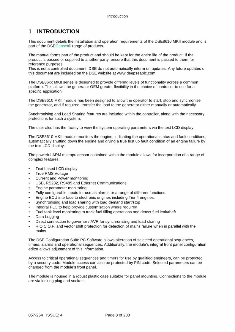
1 INTRODUCTION This document details the installation and operation requirements of the DSE8610 MKII module and is part of the DSEGenset® range of products. The manual forms part of the product and should be kept for the entire life of the product. If the product is passed or supplied to another party, ensure that this document is passed to them for reference purposes. This is not a controlled document. DSE do not automatically inform on updates. Any future updates of this document are included on the DSE website at www.deepseaplc.com The DSE86xx MKII series is designed to provide differing levels of functionality across a common platform. This allows the generator OEM greater flexibility in the choice of controller to use for a specific application. The DSE8610 MKII module has been designed to allow the operator to start, stop and synchronise the generator, and if required, transfer the load to the generator either manually or automatically. Synchronising and Load Sharing features are included within the controller, along with the necessary protections for such a system. The user also has the facility to view the system operating parameters via the text LCD display. The DSE8610 MKII module monitors the engine, indicating the operational status and fault conditions, automatically shutting down the engine and giving a true first up fault condition of an engine failure by the text LCD display. The powerful ARM microprocessor contained within the module allows for incorporation of a range of complex features: • Text based LCD display • True RMS Voltage • Current and Power monitoring • USB, RS232, RS485 and Ethernet Communications • Engine parameter monitoring. • Fully configurable inputs for use as alarms or a range of different functions. • Engine ECU interface to electronic engines including Tier 4 engines. • Synchronising and load sharing with load demand start/stop • Integral PLC to help provide customisation where required • Fuel tank level monitoring to track fuel filling operations and detect fuel leak/theft • Data Logging • Direct connection to governor / AVR for synchronising and load sharing • R.O.C.O.F. and vector shift protection for detection of mains failure when in parallel with the
mains. The DSE Configuration Suite PC Software allows alteration of selected operational sequences, timers, alarms and operational sequences. Additionally, the module’s integral front panel configuration editor allows adjustment of this information. Access to critical operational sequences and timers for use by qualified engineers, can be protected by a security code. Module access can also be protected by PIN code. Selected parameters can be changed from the module’s front panel. The module is housed in a robust plastic case suitable for panel mounting. Connections to the module are via locking plug and sockets.
Introduction
Page 9 of 208 057-254 ISSUE: 4
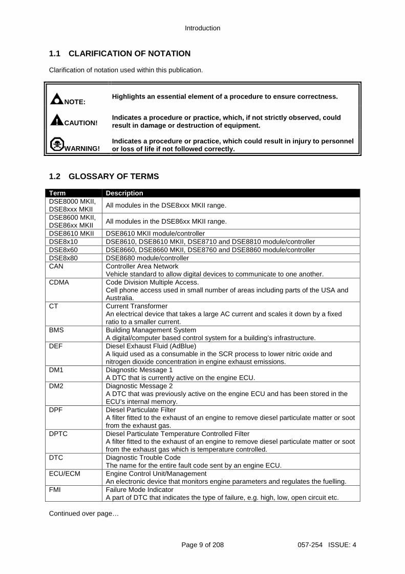
1.1 CLARIFICATION OF NOTATION Clarification of notation used within this publication.
NOTE:
Highlights an essential element of a procedure to e nsure correctness.
CAUTION!
Indicates a procedure or practice, which, if not st rictly observed, could result in damage or destruction of equipment.
WARNING!
Indicates a procedure or practice, which could resu lt in injury to personnel or loss of life if not followed correctly.
1.2 GLOSSARY OF TERMS Term Description DSE8000 MKII, DSE8xxx MKII
All modules in the DSE8xxx MKII range.
DSE8600 MKII, DSE86xx MKII
All modules in the DSE86xx MKII range.
DSE8610 MKII DSE8610 MKII module/controller DSE8x10 DSE8610, DSE8610 MKII, DSE8710 and DSE8810 module/controller DSE8x60 DSE8660, DSE8660 MKII, DSE8760 and DSE8860 module/controller DSE8x80 DSE8680 module/controller CAN Controller Area Network
Vehicle standard to allow digital devices to communicate to one another. CDMA Code Division Multiple Access.
Cell phone access used in small number of areas including parts of the USA and Australia.
CT Current Transformer An electrical device that takes a large AC current and scales it down by a fixed ratio to a smaller current.
BMS Building Management System A digital/computer based control system for a building’s infrastructure.
DEF Diesel Exhaust Fluid (AdBlue) A liquid used as a consumable in the SCR process to lower nitric oxide and nitrogen dioxide concentration in engine exhaust emissions.
DM1 Diagnostic Message 1 A DTC that is currently active on the engine ECU.
DM2 Diagnostic Message 2 A DTC that was previously active on the engine ECU and has been stored in the ECU’s internal memory.
DPF Diesel Particulate Filter A filter fitted to the exhaust of an engine to remove diesel particulate matter or soot from the exhaust gas.
DPTC Diesel Particulate Temperature Controlled Filter A filter fitted to the exhaust of an engine to remove diesel particulate matter or soot from the exhaust gas which is temperature controlled.
DTC Diagnostic Trouble Code The name for the entire fault code sent by an engine ECU.
ECU/ECM Engine Control Unit/Management An electronic device that monitors engine parameters and regulates the fuelling.
FMI Failure Mode Indicator A part of DTC that indicates the type of failure, e.g. high, low, open circuit etc.
Continued over page…
Introduction
057-254 ISSUE: 4 Page 10 of 208
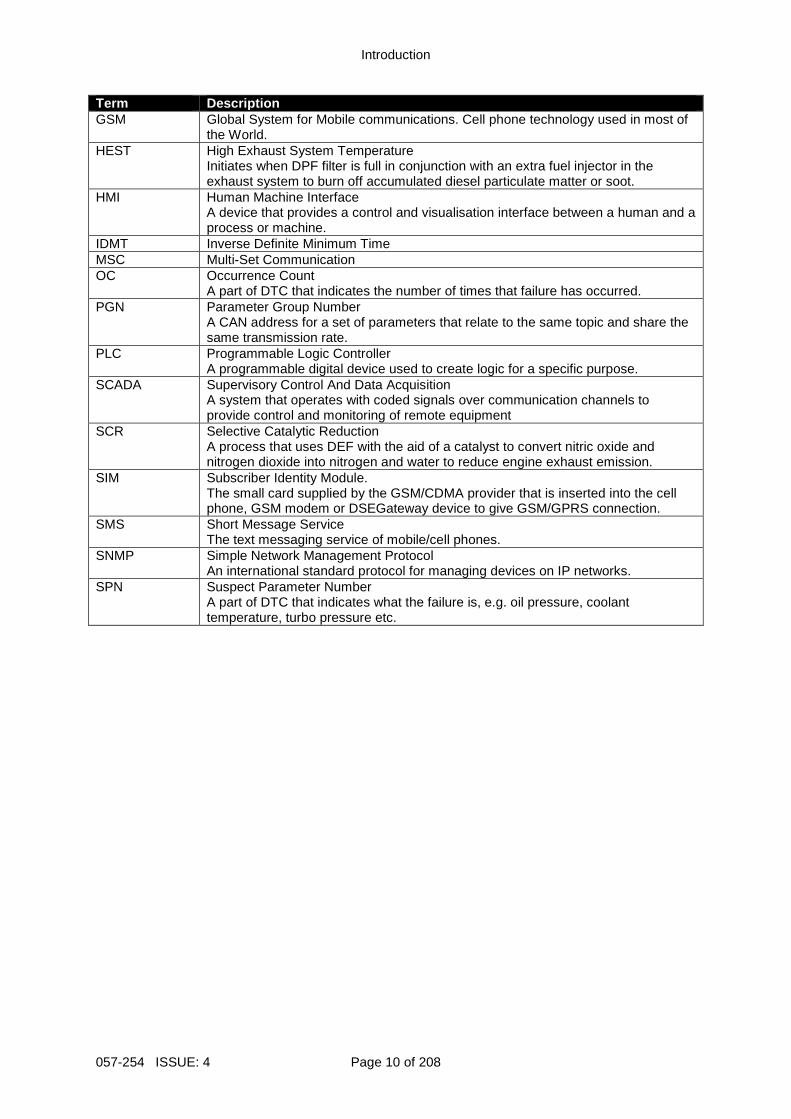
Term Description GSM Global System for Mobile communications. Cell phone technology used in most of
the World. HEST High Exhaust System Temperature
Initiates when DPF filter is full in conjunction with an extra fuel injector in the exhaust system to burn off accumulated diesel particulate matter or soot.
HMI Human Machine Interface A device that provides a control and visualisation interface between a human and a process or machine.
IDMT Inverse Definite Minimum Time MSC Multi-Set Communication OC Occurrence Count
A part of DTC that indicates the number of times that failure has occurred. PGN Parameter Group Number
A CAN address for a set of parameters that relate to the same topic and share the same transmission rate.
PLC Programmable Logic Controller A programmable digital device used to create logic for a specific purpose.
SCADA Supervisory Control And Data Acquisition A system that operates with coded signals over communication channels to provide control and monitoring of remote equipment
SCR Selective Catalytic Reduction A process that uses DEF with the aid of a catalyst to convert nitric oxide and nitrogen dioxide into nitrogen and water to reduce engine exhaust emission.
SIM Subscriber Identity Module. The small card supplied by the GSM/CDMA provider that is inserted into the cell phone, GSM modem or DSEGateway device to give GSM/GPRS connection.
SMS Short Message Service The text messaging service of mobile/cell phones.
SNMP Simple Network Management Protocol An international standard protocol for managing devices on IP networks.
SPN Suspect Parameter Number A part of DTC that indicates what the failure is, e.g. oil pressure, coolant temperature, turbo pressure etc.
Introduction
Page 11 of 208 057-254 ISSUE: 4
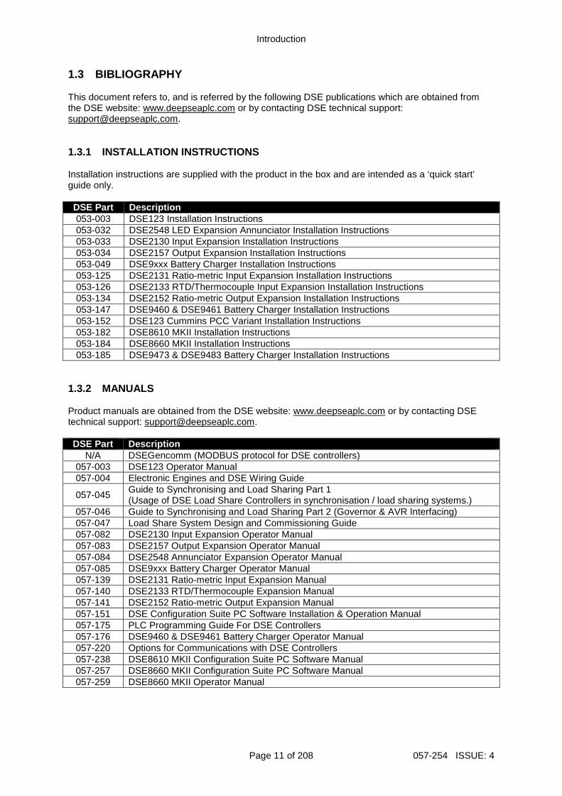
1.3 BIBLIOGRAPHY This document refers to, and is referred by the following DSE publications which are obtained from the DSE website: www.deepseaplc.com or by contacting DSE technical support: [email protected]. 1.3.1 INSTALLATION INSTRUCTIONS Installation instructions are supplied with the product in the box and are intended as a ‘quick start’ guide only. DSE Part Description 053-003 DSE123 Installation Instructions 053-032 DSE2548 LED Expansion Annunciator Installation Instructions 053-033 DSE2130 Input Expansion Installation Instructions 053-034 DSE2157 Output Expansion Installation Instructions 053-049 DSE9xxx Battery Charger Installation Instructions 053-125 DSE2131 Ratio-metric Input Expansion Installation Instructions 053-126 DSE2133 RTD/Thermocouple Input Expansion Installation Instructions 053-134 DSE2152 Ratio-metric Output Expansion Installation Instructions 053-147 DSE9460 & DSE9461 Battery Charger Installation Instructions 053-152 DSE123 Cummins PCC Variant Installation Instructions 053-182 DSE8610 MKII Installation Instructions 053-184 DSE8660 MKII Installation Instructions 053-185 DSE9473 & DSE9483 Battery Charger Installation Instructions
1.3.2 MANUALS Product manuals are obtained from the DSE website: www.deepseaplc.com or by contacting DSE technical support: [email protected]. DSE Part Description
N/A DSEGencomm (MODBUS protocol for DSE controllers) 057-003 DSE123 Operator Manual 057-004 Electronic Engines and DSE Wiring Guide
057-045 Guide to Synchronising and Load Sharing Part 1 (Usage of DSE Load Share Controllers in synchronisation / load sharing systems.)
057-046 Guide to Synchronising and Load Sharing Part 2 (Governor & AVR Interfacing) 057-047 Load Share System Design and Commissioning Guide 057-082 DSE2130 Input Expansion Operator Manual 057-083 DSE2157 Output Expansion Operator Manual 057-084 DSE2548 Annunciator Expansion Operator Manual 057-085 DSE9xxx Battery Charger Operator Manual 057-139 DSE2131 Ratio-metric Input Expansion Manual 057-140 DSE2133 RTD/Thermocouple Expansion Manual 057-141 DSE2152 Ratio-metric Output Expansion Manual 057-151 DSE Configuration Suite PC Software Installation & Operation Manual 057-175 PLC Programming Guide For DSE Controllers 057-176 DSE9460 & DSE9461 Battery Charger Operator Manual 057-220 Options for Communications with DSE Controllers 057-238 DSE8610 MKII Configuration Suite PC Software Manual 057-257 DSE8660 MKII Configuration Suite PC Software Manual 057-259 DSE8660 MKII Operator Manual
Introduction
057-254 ISSUE: 4 Page 12 of 208
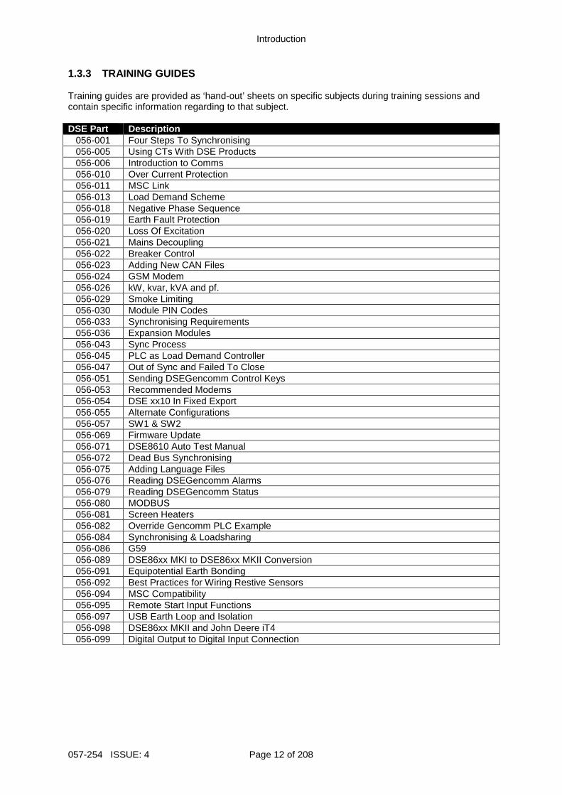
1.3.3 TRAINING GUIDES Training guides are provided as ‘hand-out’ sheets on specific subjects during training sessions and contain specific information regarding to that subject. DSE Part Description
056-001 Four Steps To Synchronising 056-005 Using CTs With DSE Products 056-006 Introduction to Comms 056-010 Over Current Protection 056-011 MSC Link 056-013 Load Demand Scheme 056-018 Negative Phase Sequence 056-019 Earth Fault Protection 056-020 Loss Of Excitation 056-021 Mains Decoupling 056-022 Breaker Control 056-023 Adding New CAN Files 056-024 GSM Modem 056-026 kW, kvar, kVA and pf. 056-029 Smoke Limiting 056-030 Module PIN Codes 056-033 Synchronising Requirements 056-036 Expansion Modules 056-043 Sync Process 056-045 PLC as Load Demand Controller 056-047 Out of Sync and Failed To Close 056-051 Sending DSEGencomm Control Keys 056-053 Recommended Modems 056-054 DSE xx10 In Fixed Export 056-055 Alternate Configurations 056-057 SW1 & SW2 056-069 Firmware Update 056-071 DSE8610 Auto Test Manual 056-072 Dead Bus Synchronising 056-075 Adding Language Files 056-076 Reading DSEGencomm Alarms 056-079 Reading DSEGencomm Status 056-080 MODBUS 056-081 Screen Heaters 056-082 Override Gencomm PLC Example 056-084 Synchronising & Loadsharing 056-086 G59 056-089 DSE86xx MKI to DSE86xx MKII Conversion 056-091 Equipotential Earth Bonding 056-092 Best Practices for Wiring Restive Sensors 056-094 MSC Compatibility 056-095 Remote Start Input Functions 056-097 USB Earth Loop and Isolation 056-098 DSE86xx MKII and John Deere iT4 056-099 Digital Output to Digital Input Connection
Introduction
Page 13 of 208 057-254 ISSUE: 4
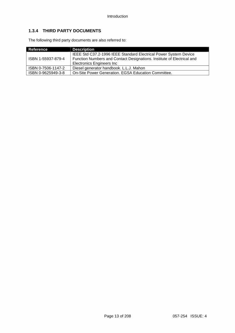
1.3.4 THIRD PARTY DOCUMENTS The following third party documents are also referred to: Reference Description
ISBN 1-55937-879-4 IEEE Std C37.2-1996 IEEE Standard Electrical Power System Device Function Numbers and Contact Designations. Institute of Electrical and Electronics Engineers Inc
ISBN 0-7506-1147-2 Diesel generator handbook. L.L.J. Mahon ISBN 0-9625949-3-8 On-Site Power Generation. EGSA Education Committee.
Specification
057-254 ISSUE: 4 Page 14 of 208
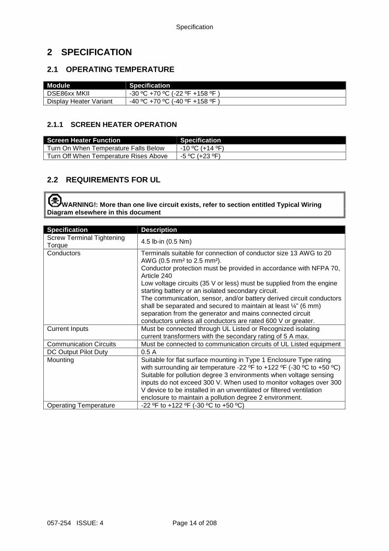
2 SPECIFICATION 2.1 OPERATING TEMPERATURE Module Specification DSE86xx MKII -30 ºC +70 ºC (-22 ºF +158 ºF ) Display Heater Variant -40 ºC +70 ºC (-40 ºF +158 ºF ) 2.1.1 SCREEN HEATER OPERATION Screen Heater Function Specification Turn On When Temperature Falls Below -10 ºC (+14 ºF) Turn Off When Temperature Rises Above -5 ºC (+23 ºF) 2.2 REQUIREMENTS FOR UL
WARNING!: More than one live circuit exists, refer to section entitled Typical Wiring Diagram elsewhere in this document Specification Description Screw Terminal Tightening Torque
4.5 lb-in (0.5 Nm)
Conductors Terminals suitable for connection of conductor size 13 AWG to 20 AWG (0.5 mm² to 2.5 mm²). Conductor protection must be provided in accordance with NFPA 70, Article 240 Low voltage circuits (35 V or less) must be supplied from the engine starting battery or an isolated secondary circuit. The communication, sensor, and/or battery derived circuit conductors shall be separated and secured to maintain at least ¼” (6 mm) separation from the generator and mains connected circuit conductors unless all conductors are rated 600 V or greater.
Current Inputs Must be connected through UL Listed or Recognized isolating current transformers with the secondary rating of 5 A max.
Communication Circuits Must be connected to communication circuits of UL Listed equipment DC Output Pilot Duty 0.5 A Mounting Suitable for flat surface mounting in Type 1 Enclosure Type rating
with surrounding air temperature -22 ºF to +122 ºF (-30 ºC to +50 ºC) Suitable for pollution degree 3 environments when voltage sensing inputs do not exceed 300 V. When used to monitor voltages over 300 V device to be installed in an unventilated or filtered ventilation enclosure to maintain a pollution degree 2 environment.
Operating Temperature -22 ºF to +122 ºF (-30 ºC to +50 ºC)
Specification
Page 15 of 208 057-254 ISSUE: 4
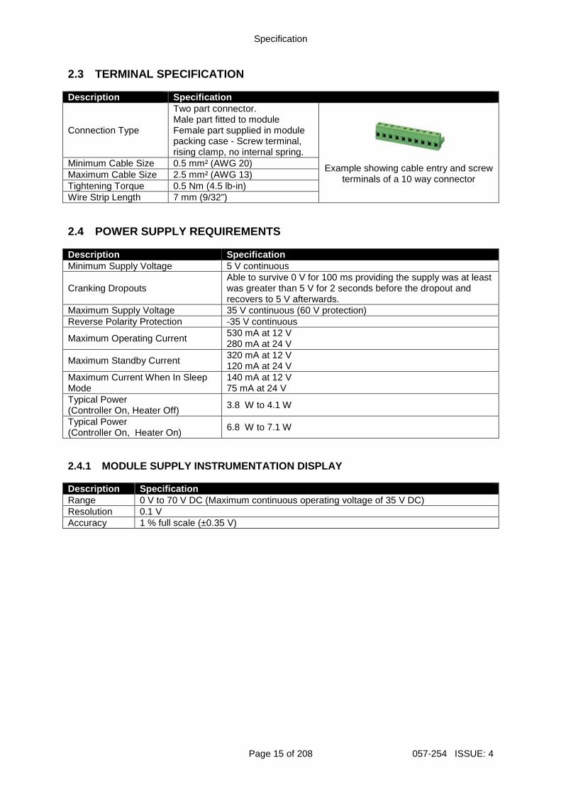
2.3 TERMINAL SPECIFICATION Description Specification
Connection Type
Two part connector. Male part fitted to module Female part supplied in module packing case - Screw terminal, rising clamp, no internal spring.
Example showing cable entry and screw
terminals of a 10 way connector
Minimum Cable Size 0.5 mm² (AWG 20) Maximum Cable Size 2.5 mm² (AWG 13) Tightening Torque 0.5 Nm (4.5 lb-in) Wire Strip Length 7 mm (9/32”) 2.4 POWER SUPPLY REQUIREMENTS Description Specification Minimum Supply Voltage 5 V continuous
Cranking Dropouts Able to survive 0 V for 100 ms providing the supply was at least was greater than 5 V for 2 seconds before the dropout and recovers to 5 V afterwards.
Maximum Supply Voltage 35 V continuous (60 V protection) Reverse Polarity Protection -35 V continuous
Maximum Operating Current 530 mA at 12 V 280 mA at 24 V
Maximum Standby Current 320 mA at 12 V 120 mA at 24 V
Maximum Current When In Sleep Mode
140 mA at 12 V 75 mA at 24 V
Typical Power (Controller On, Heater Off)
3.8 W to 4.1 W
Typical Power (Controller On, Heater On)
6.8 W to 7.1 W
2.4.1 MODULE SUPPLY INSTRUMENTATION DISPLAY Description Specification Range 0 V to 70 V DC (Maximum continuous operating voltage of 35 V DC) Resolution 0.1 V Accuracy 1 % full scale (±0.35 V)
Specification
057-254 ISSUE: 4 Page 16 of 208
2.5 VOLTAGE & FREQUENCY SENSING Description Specification Measurement Type True RMS conversion Sample Rate 40 kHz Harmonics Up to 21st or better Input Impedance 300 kΩ phase to neutral
Phase To Neutral
15 V (minimum required for sensing frequency) to 415 V AC (absolute maximum) Suitable for 345 V AC nominal (±20 % for under/overvoltage detection)
Phase To Phase
25 V (minimum required for sensing frequency) to 720 V AC (absolute maximum) Suitable for 600 V AC nominal (±20 % for under/overvoltage detection)
Common Mode Offset From Earth 100 V AC (max)
Resolution 1 V AC phase to neutral 2 V AC phase to phase
Accuracy ±1 % of full scale phase to neutral ±1 % of full scale phase to phase
Minimum Frequency 3.5 Hz Maximum Frequency 75.0 Hz Frequency Resolution 0.1 Hz Frequency Accuracy ±0.05 Hz 2.6 CURRENT SENSING Description Specification Measurement Type True RMS conversion Sample Rate 40 kHz Harmonics Up to 21st or better Nominal CT Secondary Rating 1 A and 5 A Maximum Continuous Current 5 A Overload Measurement 15 A Absolute Maximum Overload 50 A for 1 second Burden 0.5 VA (0.02 Ω current shunts)
Common Mode Offset 70 V peak plant ground to CT common terminal under fault condition
Resolution 25 mA Accuracy ±1 % of Nominal (excluding CT error)
Specification
Page 17 of 208 057-254 ISSUE: 4
2.6.1 VA RATING OF THE CTS
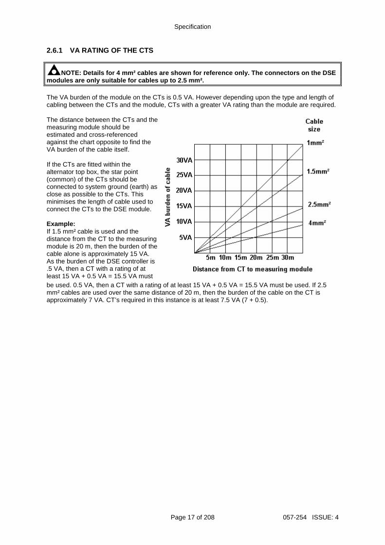
NOTE: Details for 4 mm² cables are shown for refere nce only. The connectors on the DSE modules are only suitable for cables up to 2.5 mm². The VA burden of the module on the CTs is 0.5 VA. However depending upon the type and length of cabling between the CTs and the module, CTs with a greater VA rating than the module are required. The distance between the CTs and the measuring module should be estimated and cross-referenced against the chart opposite to find the VA burden of the cable itself. If the CTs are fitted within the alternator top box, the star point (common) of the CTs should be connected to system ground (earth) as close as possible to the CTs. This minimises the length of cable used to connect the CTs to the DSE module. Example: If 1.5 mm² cable is used and the distance from the CT to the measuring module is 20 m, then the burden of the cable alone is approximately 15 VA. As the burden of the DSE controller is .5 VA, then a CT with a rating of at least 15 VA + 0.5 VA = 15.5 VA must
be used. 0.5 VA, then a CT with a rating of at least 15 VA + 0.5 VA = 15.5 VA must be used. If 2.5 mm² cables are used over the same distance of 20 m, then the burden of the cable on the CT is approximately 7 VA. CT’s required in this instance is at least 7.5 VA (7 + 0.5).
Specification
057-254 ISSUE: 4 Page 18 of 208
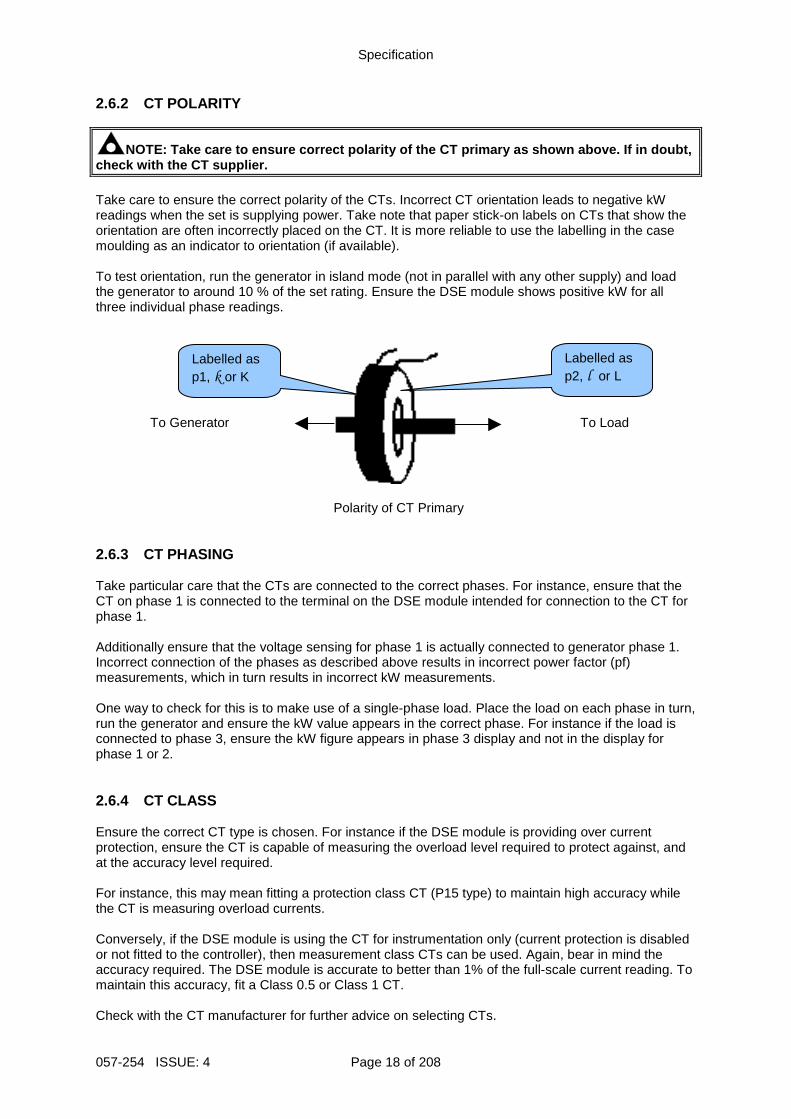
2.6.2 CT POLARITY
NOTE: Take care to ensure correct polarity of the C T primary as shown above. If in doubt, check with the CT supplier. Take care to ensure the correct polarity of the CTs. Incorrect CT orientation leads to negative kW readings when the set is supplying power. Take note that paper stick-on labels on CTs that show the orientation are often incorrectly placed on the CT. It is more reliable to use the labelling in the case moulding as an indicator to orientation (if available). To test orientation, run the generator in island mode (not in parallel with any other supply) and load the generator to around 10 % of the set rating. Ensure the DSE module shows positive kW for all three individual phase readings.
To Generator
To Load
Polarity of CT Primary
2.6.3 CT PHASING Take particular care that the CTs are connected to the correct phases. For instance, ensure that the CT on phase 1 is connected to the terminal on the DSE module intended for connection to the CT for phase 1. Additionally ensure that the voltage sensing for phase 1 is actually connected to generator phase 1. Incorrect connection of the phases as described above results in incorrect power factor (pf) measurements, which in turn results in incorrect kW measurements. One way to check for this is to make use of a single-phase load. Place the load on each phase in turn, run the generator and ensure the kW value appears in the correct phase. For instance if the load is connected to phase 3, ensure the kW figure appears in phase 3 display and not in the display for phase 1 or 2. 2.6.4 CT CLASS Ensure the correct CT type is chosen. For instance if the DSE module is providing over current protection, ensure the CT is capable of measuring the overload level required to protect against, and at the accuracy level required. For instance, this may mean fitting a protection class CT (P15 type) to maintain high accuracy while the CT is measuring overload currents. Conversely, if the DSE module is using the CT for instrumentation only (current protection is disabled or not fitted to the controller), then measurement class CTs can be used. Again, bear in mind the accuracy required. The DSE module is accurate to better than 1% of the full-scale current reading. To maintain this accuracy, fit a Class 0.5 or Class 1 CT. Check with the CT manufacturer for further advice on selecting CTs.
Labelled as p1, k or K
Labelled as p2, l or L
Specification
Page 19 of 208 057-254 ISSUE: 4
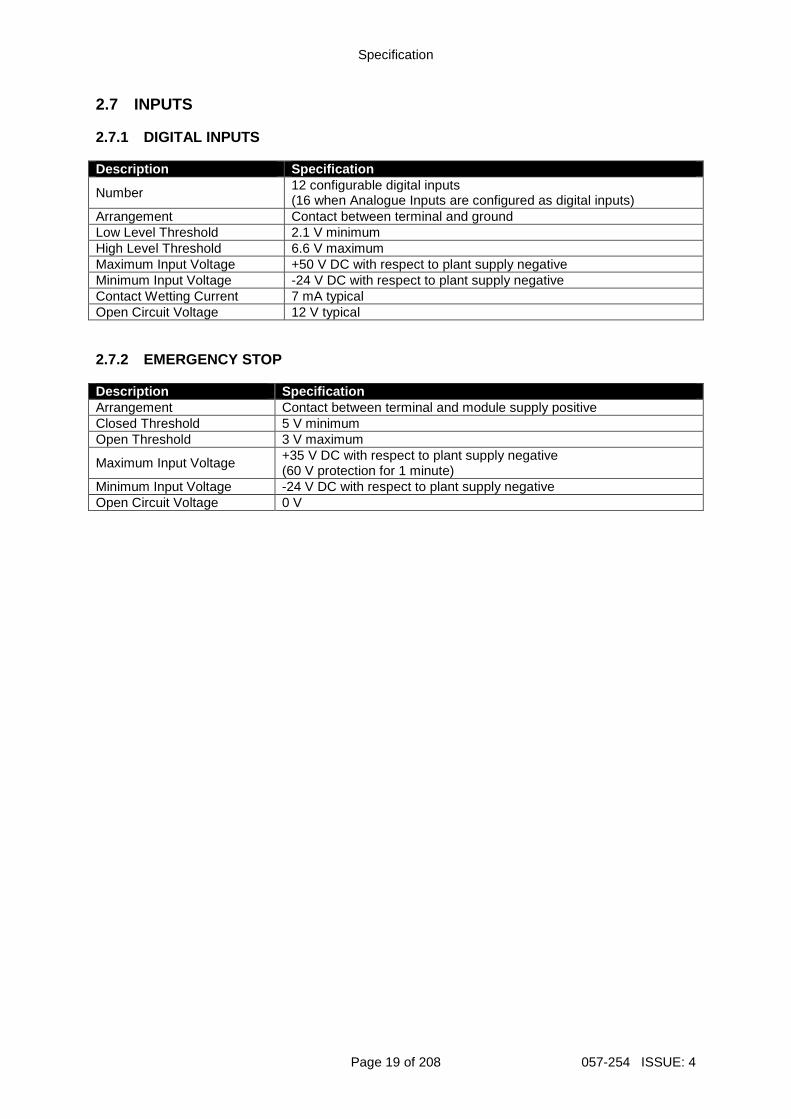
2.7 INPUTS 2.7.1 DIGITAL INPUTS Description Specification
Number 12 configurable digital inputs (16 when Analogue Inputs are configured as digital inputs)
Arrangement Contact between terminal and ground Low Level Threshold 2.1 V minimum High Level Threshold 6.6 V maximum Maximum Input Voltage +50 V DC with respect to plant supply negative Minimum Input Voltage -24 V DC with respect to plant supply negative Contact Wetting Current 7 mA typical Open Circuit Voltage 12 V typical 2.7.2 EMERGENCY STOP Description Specification Arrangement Contact between terminal and module supply positive Closed Threshold 5 V minimum Open Threshold 3 V maximum
Maximum Input Voltage +35 V DC with respect to plant supply negative (60 V protection for 1 minute)
Minimum Input Voltage -24 V DC with respect to plant supply negative Open Circuit Voltage 0 V
Specification
057-254 ISSUE: 4 Page 20 of 208
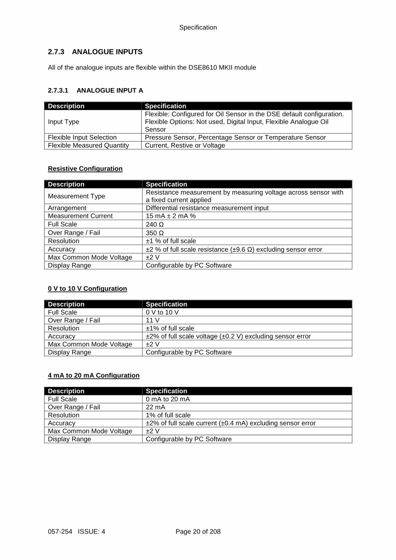
2.7.3 ANALOGUE INPUTS All of the analogue inputs are flexible within the DSE8610 MKII module 2.7.3.1 ANALOGUE INPUT A Description Specification
Input Type Flexible: Configured for Oil Sensor in the DSE default configuration. Flexible Options: Not used, Digital Input, Flexible Analogue Oil Sensor
Flexible Input Selection Pressure Sensor, Percentage Sensor or Temperature Sensor Flexible Measured Quantity Current, Restive or Voltage Resistive Configuration Description Specification
Measurement Type Resistance measurement by measuring voltage across sensor with a fixed current applied
Arrangement Differential resistance measurement input Measurement Current 15 mA ± 2 mA % Full Scale 240 Ω Over Range / Fail 350 Ω Resolution ±1 % of full scale Accuracy ±2 % of full scale resistance (±9.6 Ω) excluding sensor error Max Common Mode Voltage ±2 V Display Range Configurable by PC Software 0 V to 10 V Configuration Description Specification Full Scale 0 V to 10 V Over Range / Fail 11 V Resolution ±1% of full scale Accuracy ±2% of full scale voltage (±0.2 V) excluding sensor error Max Common Mode Voltage ±2 V Display Range Configurable by PC Software 4 mA to 20 mA Configuration Description Specification Full Scale 0 mA to 20 mA Over Range / Fail 22 mA Resolution 1% of full scale Accuracy ±2% of full scale current (±0.4 mA) excluding sensor error Max Common Mode Voltage ±2 V Display Range Configurable by PC Software
Specification
Page 21 of 208 057-254 ISSUE: 4
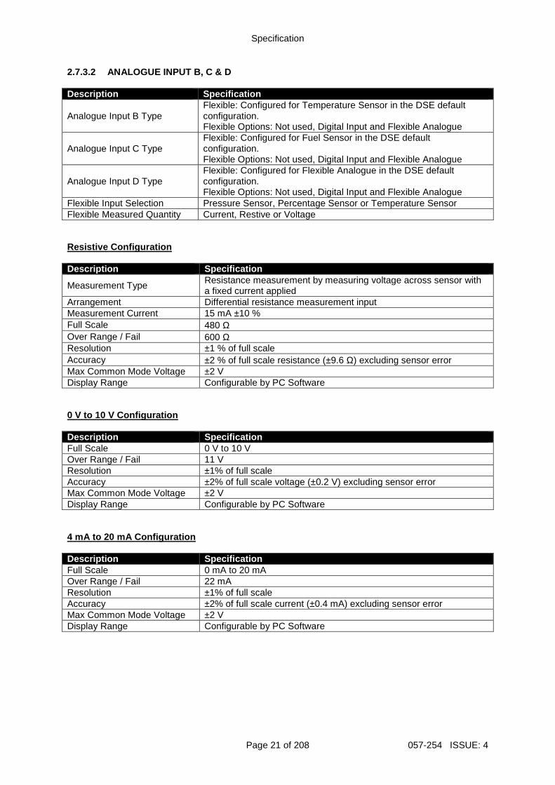
2.7.3.2 ANALOGUE INPUT B, C & D Description Specification
Analogue Input B Type Flexible: Configured for Temperature Sensor in the DSE default configuration. Flexible Options: Not used, Digital Input and Flexible Analogue
Analogue Input C Type Flexible: Configured for Fuel Sensor in the DSE default configuration. Flexible Options: Not used, Digital Input and Flexible Analogue
Analogue Input D Type Flexible: Configured for Flexible Analogue in the DSE default configuration. Flexible Options: Not used, Digital Input and Flexible Analogue
Flexible Input Selection Pressure Sensor, Percentage Sensor or Temperature Sensor Flexible Measured Quantity Current, Restive or Voltage Resistive Configuration Description Specification
Measurement Type Resistance measurement by measuring voltage across sensor with a fixed current applied
Arrangement Differential resistance measurement input Measurement Current 15 mA ±10 % Full Scale 480 Ω Over Range / Fail 600 Ω Resolution ±1 % of full scale Accuracy ±2 % of full scale resistance (±9.6 Ω) excluding sensor error Max Common Mode Voltage ±2 V Display Range Configurable by PC Software 0 V to 10 V Configuration Description Specification Full Scale 0 V to 10 V Over Range / Fail 11 V Resolution ±1% of full scale Accuracy ±2% of full scale voltage (±0.2 V) excluding sensor error Max Common Mode Voltage ±2 V Display Range Configurable by PC Software 4 mA to 20 mA Configuration Description Specification Full Scale 0 mA to 20 mA Over Range / Fail 22 mA Resolution ±1% of full scale Accuracy ±2% of full scale current (±0.4 mA) excluding sensor error Max Common Mode Voltage ±2 V Display Range Configurable by PC Software
Specification
057-254 ISSUE: 4 Page 22 of 208
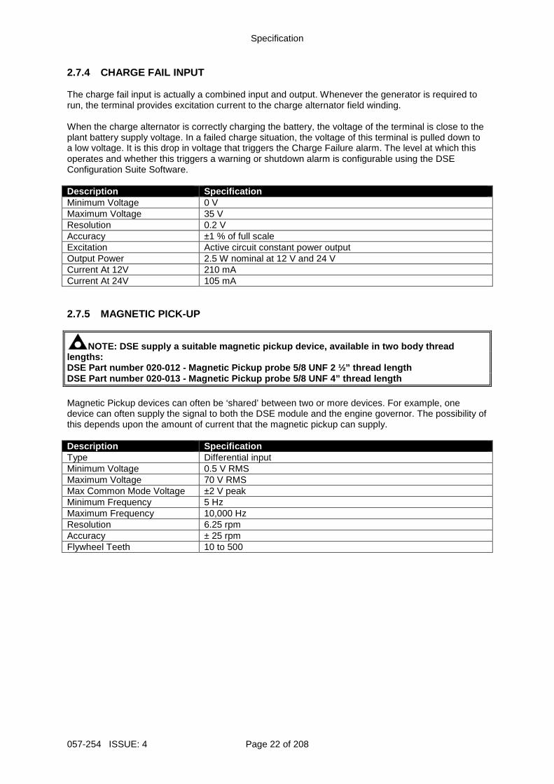
2.7.4 CHARGE FAIL INPUT The charge fail input is actually a combined input and output. Whenever the generator is required to run, the terminal provides excitation current to the charge alternator field winding. When the charge alternator is correctly charging the battery, the voltage of the terminal is close to the plant battery supply voltage. In a failed charge situation, the voltage of this terminal is pulled down to a low voltage. It is this drop in voltage that triggers the Charge Failure alarm. The level at which this operates and whether this triggers a warning or shutdown alarm is configurable using the DSE Configuration Suite Software. Description Specification Minimum Voltage 0 V Maximum Voltage 35 V Resolution 0.2 V Accuracy ±1 % of full scale Excitation Active circuit constant power output Output Power 2.5 W nominal at 12 V and 24 V Current At 12V 210 mA Current At 24V 105 mA 2.7.5 MAGNETIC PICK-UP
NOTE: DSE supply a suitable magnetic pickup device, available in two body thread lengths: DSE Part number 020-012 - Magnetic Pickup probe 5/8 UNF 2 ½” thread length DSE Part number 020-013 - Magnetic Pickup probe 5/8 UNF 4” thread length Magnetic Pickup devices can often be ‘shared’ between two or more devices. For example, one device can often supply the signal to both the DSE module and the engine governor. The possibility of this depends upon the amount of current that the magnetic pickup can supply. Description Specification Type Differential input Minimum Voltage 0.5 V RMS Maximum Voltage 70 V RMS Max Common Mode Voltage ±2 V peak Minimum Frequency 5 Hz Maximum Frequency 10,000 Hz Resolution 6.25 rpm Accuracy ± 25 rpm Flywheel Teeth 10 to 500
Specification
Page 23 of 208 057-254 ISSUE: 4
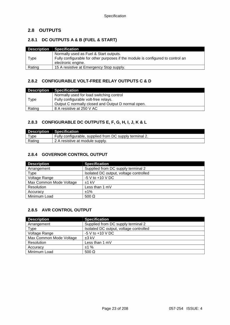
2.8 OUTPUTS 2.8.1 DC OUTPUTS A & B (FUEL & START) Description Specification
Type Normally used as Fuel & Start outputs. Fully configurable for other purposes if the module is configured to control an electronic engine.
Rating 15 A resistive at Emergency Stop supply. 2.8.2 CONFIGURABLE VOLT-FREE RELAY OUTPUTS C & D Description Specification
Type Normally used for load switching control Fully configurable volt-free relays. Output C normally closed and Output D normal open.
Rating 8 A resistive at 250 V AC 2.8.3 CONFIGURABLE DC OUTPUTS E, F, G, H, I, J, K & L Description Specification Type Fully configurable, supplied from DC supply terminal 2. Rating 2 A resistive at module supply. 2.8.4 GOVERNOR CONTROL OUTPUT Description Specification Arrangement Supplied from DC supply terminal 2 Type Isolated DC output, voltage controlled Voltage Range -5 V to +10 V DC Max Common Mode Voltage ±1 kV Resolution Less than 1 mV Accuracy ±1% Minimum Load 500 Ω 2.8.5 AVR CONTROL OUTPUT Description Specification Arrangement Supplied from DC supply terminal 2 Type Isolated DC output, voltage controlled Voltage Range -5 V to +10 V DC Max Common Mode Voltage ±3 kV Resolution Less than 1 mV Accuracy ±1 % Minimum Load 500 Ω
Specification
057-254 ISSUE: 4 Page 24 of 208
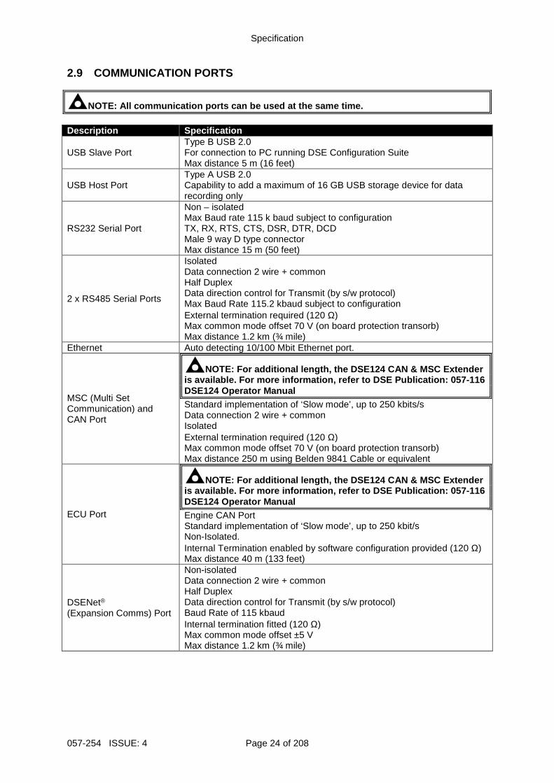
2.9 COMMUNICATION PORTS
NOTE: All communication ports can be used at the sa me time. Description Specification
USB Slave Port Type B USB 2.0 For connection to PC running DSE Configuration Suite Max distance 5 m (16 feet)
USB Host Port Type A USB 2.0 Capability to add a maximum of 16 GB USB storage device for data recording only
RS232 Serial Port
Non – isolated Max Baud rate 115 k baud subject to configuration TX, RX, RTS, CTS, DSR, DTR, DCD Male 9 way D type connector Max distance 15 m (50 feet)
2 x RS485 Serial Ports
Isolated Data connection 2 wire + common Half Duplex Data direction control for Transmit (by s/w protocol) Max Baud Rate 115.2 kbaud subject to configuration External termination required (120 Ω) Max common mode offset 70 V (on board protection transorb) Max distance 1.2 km (¾ mile)
Ethernet Auto detecting 10/100 Mbit Ethernet port.
MSC (Multi Set Communication) and CAN Port
NOTE: For additional length, the DSE124 CAN & MSC E xtender is available. For more information, refer to DSE Pu blication: 057-116 DSE124 Operator Manual Standard implementation of ‘Slow mode’, up to 250 kbits/s Data connection 2 wire + common Isolated External termination required (120 Ω) Max common mode offset 70 V (on board protection transorb) Max distance 250 m using Belden 9841 Cable or equivalent
ECU Port
NOTE: For additional length, the DSE124 CAN & MSC E xtender is available. For more information, refer to DSE Pu blication: 057-116 DSE124 Operator Manual Engine CAN Port Standard implementation of ‘Slow mode’, up to 250 kbit/s Non-Isolated. Internal Termination enabled by software configuration provided (120 Ω) Max distance 40 m (133 feet)
DSENet® (Expansion Comms) Port
Non-isolated Data connection 2 wire + common Half Duplex Data direction control for Transmit (by s/w protocol) Baud Rate of 115 kbaud Internal termination fitted (120 Ω) Max common mode offset ±5 V Max distance 1.2 km (¾ mile)
Specification
Page 25 of 208 057-254 ISSUE: 4
2.10 COMMUNICATION PORT USAGE 2.10.1 USB SLAVE PORT (PC CONFIGURATION)
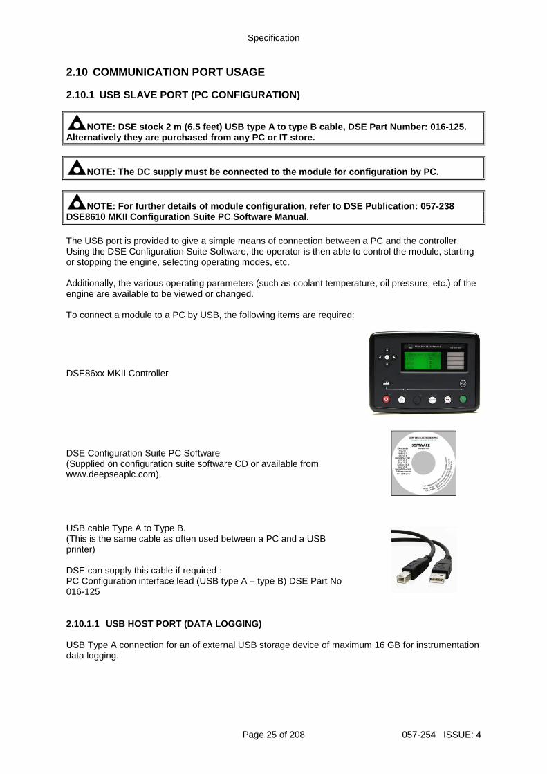
NOTE: DSE stock 2 m (6.5 feet) USB type A to type B cable, DSE Part Number: 016-125. Alternatively they are purchased from any PC or IT store.
NOTE: The DC supply must be connected to the module for configuration by PC.
NOTE: For further details of module configuration, refer to DSE Publication: 057-238 DSE8610 MKII Configuration Suite PC Software Manual . The USB port is provided to give a simple means of connection between a PC and the controller. Using the DSE Configuration Suite Software, the operator is then able to control the module, starting or stopping the engine, selecting operating modes, etc. Additionally, the various operating parameters (such as coolant temperature, oil pressure, etc.) of the engine are available to be viewed or changed. To connect a module to a PC by USB, the following items are required:
DSE86xx MKII Controller
DSE Configuration Suite PC Software (Supplied on configuration suite software CD or available from www.deepseaplc.com).
USB cable Type A to Type B. (This is the same cable as often used between a PC and a USB printer) DSE can supply this cable if required : PC Configuration interface lead (USB type A – type B) DSE Part No 016-125
2.10.1.1 USB HOST PORT (DATA LOGGING) USB Type A connection for an of external USB storage device of maximum 16 GB for instrumentation data logging.
Specification
057-254 ISSUE: 4 Page 26 of 208
2.10.2 RS232 PORT
NOTE: For direct connection an RS232 null modem (cr ossover) cable is required. This is rated to a maximum cable length of 15 m.
NOTE: For a single module to PC connection and dist ances up to 6 m (20 feet) the USB connection method is more suitable and provides for a lower cost alternative to RS485 (which is more suited to longer distance connections). The RS232 port on the controller supports the MODBUS RTU protocol and is for connection to a single MODBUS master device only. The MODBUS register table for the controller is available upon request from the DSE Technical Support Department. RS232 is for short distance communication (max 15m) and is typically used to connect the controller to a telephone or GSM modem for more remote communications. The various operating parameters (such as coolant temperature, oil pressure, etc.) of the remote engine are viewed or changed. Many PCs are not fitted with an internal RS232 serial port. DSE DOES NOT recommend the use of USB to RS232 convertors but can recommend PC add-ons to provide the computer with an RS232 port. 2.10.2.1 RECOMMENDED EXTERNAL MODEMS
NOTE: For GSM modems a SIM card is required, suppli ed by the GSM network provider: For SMS only, a ‘normal’ voice SIM card is required . This enables the controller to send SMS messages to designated mobile phones upon status an d alarm conditions. For a data connection to a PC running DSE Configura tion Suite Software, a ‘special’ CSD (Circuit Switched Data) SIM card is required that e nables the modem to answer an incoming data call. Many ‘pay as you go’ services do not pro vide a CSD (Circuit Switched Data) SIM card.
Multitech Global Modem – MultiModem ZBA (PSTN) DSE Part Number 020-252 (Contact DSE Sales for details of localisation kits for these modems)
Sierra Fastrak Xtend GSM modem kit (PSU, Antenna and modem)* DSE Part number 0830-001-01
Specification
Page 27 of 208 057-254 ISSUE: 4
2.10.2.2 RECOMMENDED PC RS232 SERIAL PORT ADD-ONS
NOTE: DSE have no business tie to Brainboxes. Over many years, our own engineers have used these products and are happy to recommend them.
NOTE: For further details of setting up the devices below, refer to the manufacture whose details are below. Remember to check these parts are suitable for your PC. Consult your PC supplier for further advice.
Brainboxes PM143 PCMCIA RS232 card (for laptop PCs)
Brainboxes VX-001 Express Card RS232 (for laptops and nettops PCs)
Brainboxes UC246 PCI RS232 card (for desktop PCs)
Brainboxes PX-246 PCI Express 1 Port RS232 1 x 9 Pin (for desktop PCs)
Supplier: Brainboxes Tel: +44 (0)151 220 2500 Web: http://www.brainboxes.com Email: Sales: [email protected]
Specification
057-254 ISSUE: 4 Page 28 of 208
2.10.3 RS485 PORT
NOTE: For a single module to PC connection and dist ances up to 6 m (20 feet) the USB connection method is more suitable and provides for a lower cost alternative to RS485 (which is more suited to longer distance connections). The RS485 port on the controller supports the MODBUS RTU protocol and is for connection to a single MODBUS master device only. The DSE MODBUS register table for the controller is available upon request from the DSE Technical Support Department. RS485 is used for point-to-point cable connection of more than one device (maximum 32 devices) and allows for connection to PCs, PLCs and Building Management Systems (to name just a few devices). One advantage of the RS485 interface is the large distance specification (1.2 km when using Belden 9841 (or equivalent) cable. This allows for a large distance between the module and a PC running the DSE Configuration Suite software. The operator is then able to control the module, starting or stopping the engine, selecting operating modes, etc. The various operating parameters (such as coolant temperature, oil pressure, etc.) of the remote engine are viewed or changed. Many PCs are not fitted with an internal RS485 serial port. DSE DOES NOT recommend the use of USB to RS485 convertors but can recommend PC add-ons to provide the computer with an RS485 port. 2.10.3.1 CABLE SPECIFICATION
NOTE: DSE recommend Belden 9841 (or equivalent) cab le for RS485 communication. This is rated to a maximum cable length of 1.2 km. DSE S tock Belden 9841 cable, DSE Part Number: 016-030. Description Specification Cable Type Two core screened and shielded twisted pair
Cable Characteristics 120 Ω impedance Low capacitance
Recommended Cable Belden 9841 Belden 9271
Maximum Cable Length 1200 m (¾ mile) when using Belden 9841 or direct equivalent. 600 m (656 yards) when using Belden 9271 or direct equivalent.
RS485 Topology “Daisy Chain” Bus with no stubs (spurs)
RS485 Termination 120 Ω. Not fitted internally to module. Must be fitted externally to the ‘first’ and ‘last’ device on the RS485 link.
Specification
Page 29 of 208 057-254 ISSUE: 4
2.10.3.2 RECOMMENDED PC RS485 SERIAL PORT ADD-ONS
NOTE: DSE have no business tie to Brainboxes. Over many years, our own engineers have used these products and are happy to recommend them.
NOTE: For further details of setting up the devices below, refer to the manufacture whose details are below. Remember to check these parts are suitable for your PC. Consult your PC supplier for further advice.
Brainboxes PM154 PCMCIA RS485 card (for laptops PCs) Set to ‘Half Duplex, Autogating” with ‘CTS True’ set to ‘enabled’
Brainboxes VX-023 ExpressCard 1 Port RS422/485 (for laptops and nettop PCs)
Brainboxes UC320 PCI Velocity RS485 card (for desktop PCs) Set to ‘Half Duplex, Autogating” with ‘CTS True’ set to ‘enabled’
Brainboxes PX-324 PCI Express 1 Port RS422/485 (for desktop PCs)
Supplier: Brainboxes Tel: +44 (0)151 220 2500 Web: http://www.brainboxes.com Email: Sales: [email protected]
Specification
057-254 ISSUE: 4 Page 30 of 208
2.10.3.3 RS485 USED FOR MODBUS ENGINE CONNECTION
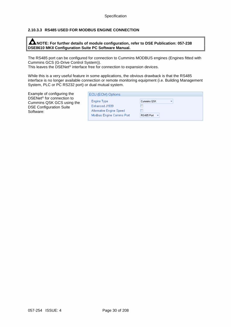
NOTE: For further details of module configuration, refer to DSE Publication: 057-238 DSE8610 MKII Configuration Suite PC Software Manual . The RS485 port can be configured for connection to Cummins MODBUS engines (Engines fitted with Cummins GCS (G-Drive Control System)). This leaves the DSENet® interface free for connection to expansion devices. While this is a very useful feature in some applications, the obvious drawback is that the RS485 interface is no longer available connection or remote monitoring equipment (i.e. Building Management System, PLC or PC RS232 port) or dual mutual system. Example of configuring the DSENet® for connection to Cummins QSK GCS using the DSE Configuration Suite Software:
Specification
Page 31 of 208 057-254 ISSUE: 4
2.10.4 ETHERNET PORT
NOTE: For further details of module configuration, refer to DSE Publication: 057-238 DSE8610 MKII Configuration Suite PC Software Manual .
NOTE: For a single module to PC connection and dist ances up to 6 m (20 feet) the USB connection method is more suitable and provides for a lower cost alternative to Ethernet (which is more suited to longer distance connection s).
NOTE: DSE stock 2 m (6.5 feet) Ethernet Cable, DSE Part Number: 016-137. Alternatively they can be purchased from any PC or IT store. Ethernet is used for point-to-point cable connection of more than one device and allows for connection to PCs, PLCs, Building Management Systems and SNMP Managers (to name just a few devices). One advantage of the Ethernet interface is the ability to interface into an existing LAN (Local Area Network) connection for remote connection via an internet connection. This allows for a large distance between the module and a PC running the DSE Configuration Suite software or any external device. The operator is then able to control the module, starting or stopping the engine, selecting operating modes, etc through various different means. 2.10.4.1 MODBUS TCP The Ethernet port on the controller supports the Modbus TCP protocol and is for connection for up to five Modbus master devices. The various operating parameters (such as coolant temperature, oil pressure, etc.) of the remote engine are viewed or changed. The DSE MODBUS register table for the controller is available upon request from the DSE Technical Support Department.
Specification
057-254 ISSUE: 4 Page 32 of 208
2.10.4.2 SNMP
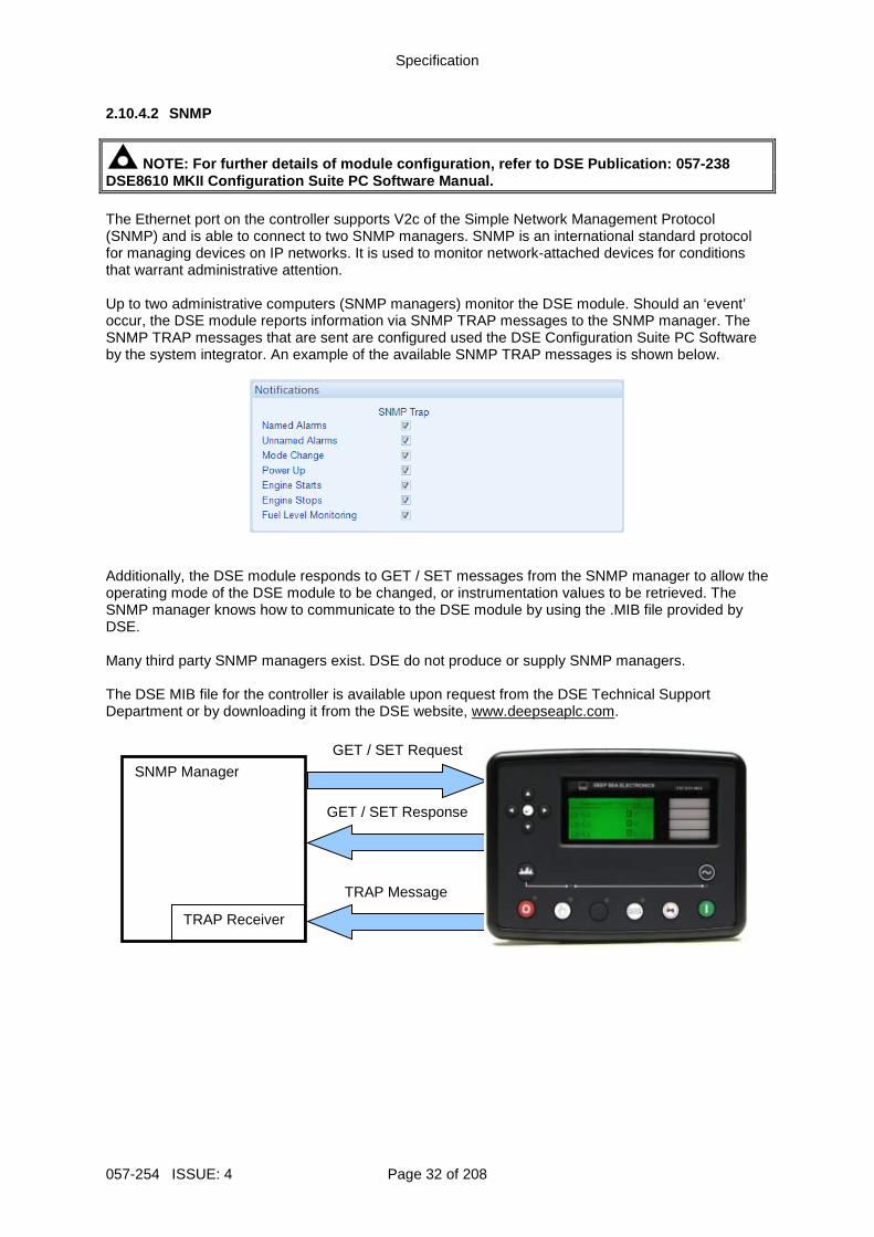
NOTE: For further details of module configuration, refer to DSE Publication: 057-238 DSE8610 MKII Configuration Suite PC Software Manual . The Ethernet port on the controller supports V2c of the Simple Network Management Protocol (SNMP) and is able to connect to two SNMP managers. SNMP is an international standard protocol for managing devices on IP networks. It is used to monitor network-attached devices for conditions that warrant administrative attention. Up to two administrative computers (SNMP managers) monitor the DSE module. Should an ‘event’ occur, the DSE module reports information via SNMP TRAP messages to the SNMP manager. The SNMP TRAP messages that are sent are configured used the DSE Configuration Suite PC Software by the system integrator. An example of the available SNMP TRAP messages is shown below.
Additionally, the DSE module responds to GET / SET messages from the SNMP manager to allow the operating mode of the DSE module to be changed, or instrumentation values to be retrieved. The SNMP manager knows how to communicate to the DSE module by using the .MIB file provided by DSE. Many third party SNMP managers exist. DSE do not produce or supply SNMP managers. The DSE MIB file for the controller is available upon request from the DSE Technical Support Department or by downloading it from the DSE website, www.deepseaplc.com.
GET / SET Request
SNMP Manager
GET / SET Response
TRAP Message
TRAP Receiver
Specification
Page 33 of 208 057-254 ISSUE: 4
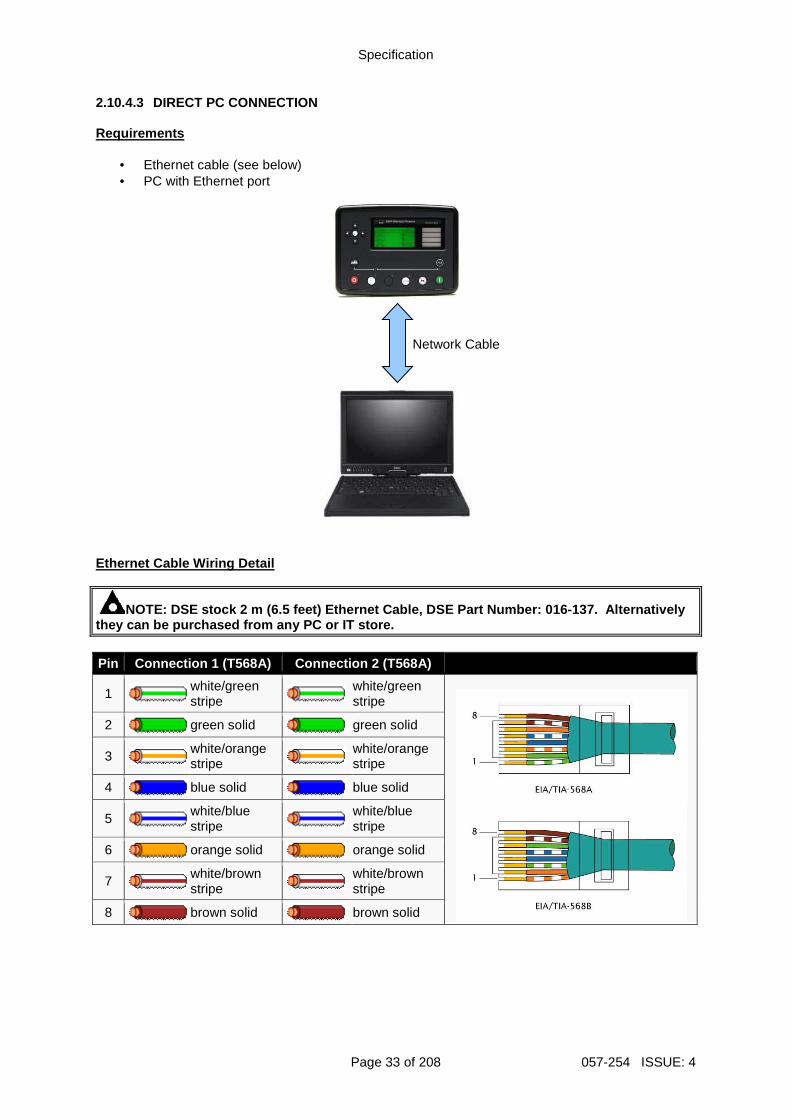
2.10.4.3 DIRECT PC CONNECTION Requirements
• Ethernet cable (see below) • PC with Ethernet port
Ethernet Cable Wiring Detail
NOTE: DSE stock 2 m (6.5 feet) Ethernet Cable, DSE Part Number: 016-137. Alternatively they can be purchased from any PC or IT store. Pin Connection 1 (T568A) Connection 2 (T568A)
1
white/green stripe
white/green stripe
2
green solid
green solid
3
white/orange stripe
white/orange stripe
4
blue solid
blue solid
5
white/blue stripe
white/blue stripe
6
orange solid
orange solid
7
white/brown stripe
white/brown stripe
8
brown solid
brown solid
Network Cable
Specification
057-254 ISSUE: 4 Page 34 of 208
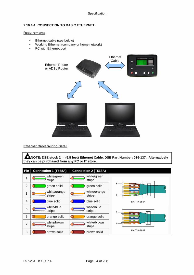
2.10.4.4 CONNECTION TO BASIC ETHERNET Requirements
• Ethernet cable (see below) • Working Ethernet (company or home network) • PC with Ethernet port
Ethernet Cable Wiring Detail
NOTE: DSE stock 2 m (6.5 feet) Ethernet Cable, DSE Part Number: 016-137. Alternatively they can be purchased from any PC or IT store. Pin Connection 1 (T568A) Connection 2 (T568A)
1
white/green stripe
white/green stripe
2
green solid
green solid
3
white/orange stripe
white/orange stripe
4
blue solid
blue solid
5
white/blue stripe
white/blue stripe
6
orange solid
orange solid
7
white/brown stripe
white/brown stripe
8
brown solid
brown solid
Ethernet Router or ADSL Router
Ethernet Cable
Specification
Page 35 of 208 057-254 ISSUE: 4
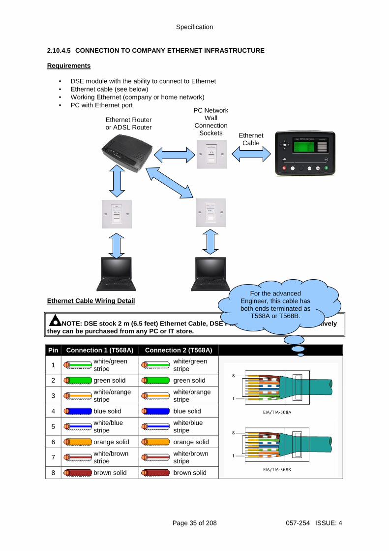
2.10.4.5 CONNECTION TO COMPANY ETHERNET INFRASTRUCTURE Requirements
• DSE module with the ability to connect to Ethernet • Ethernet cable (see below) • Working Ethernet (company or home network) • PC with Ethernet port
Ethernet Cable Wiring Detail
NOTE: DSE stock 2 m (6.5 feet) Ethernet Cable, DSE Part Number: 016-137. Alternatively they can be purchased from any PC or IT store. Pin Connection 1 (T568A) Connection 2 (T568A)
1
white/green stripe
white/green stripe
2
green solid
green solid
3
white/orange stripe
white/orange stripe
4
blue solid
blue solid
5
white/blue stripe
white/blue stripe
6
orange solid
orange solid
7
white/brown stripe
white/brown stripe
8
brown solid
brown solid
PC Network Wall
Connection Sockets
Ethernet Router or ADSL Router
Ethernet Cable
For the advanced Engineer, this cable has both ends terminated as
T568A or T568B.
Specification
057-254 ISSUE: 4 Page 36 of 208
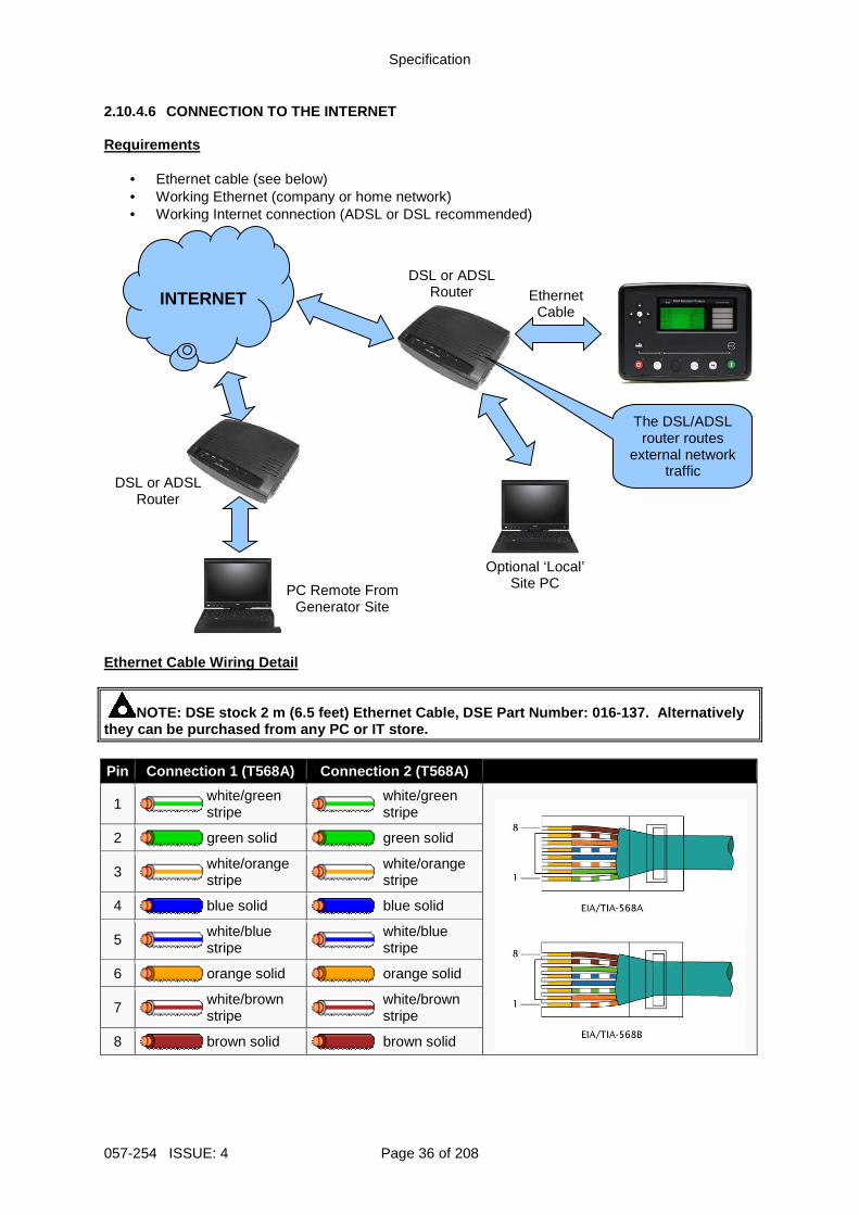
2.10.4.6 CONNECTION TO THE INTERNET Requirements
• Ethernet cable (see below) • Working Ethernet (company or home network) • Working Internet connection (ADSL or DSL recommended)
Ethernet Cable Wiring Detail
NOTE: DSE stock 2 m (6.5 feet) Ethernet Cable, DSE Part Number: 016-137. Alternatively they can be purchased from any PC or IT store. Pin Connection 1 (T568A) Connection 2 (T568A)
1
white/green stripe
white/green stripe
2
green solid
green solid
3
white/orange stripe
white/orange stripe
4
blue solid
blue solid
5
white/blue stripe
white/blue stripe
6
orange solid
orange solid
7
white/brown stripe
white/brown stripe
8
brown solid
brown solid
DSL or ADSL Router
Optional ‘Local’ Site PC
INTERNET
PC Remote From Generator Site
The DSL/ADSL router routes
external network traffic
Ethernet Cable
DSL or ADSL Router
Specification
Page 37 of 208 057-254 ISSUE: 4
2.10.4.7 FIREWALL CONFIGURATION FOR INTERNET ACCESS
NOTE: For further details of module configuration, refer to DSE Publication: 057-238 DSE8610 MKII Configuration Suite PC Software Manual . As modem/routers differ enormously in their configuration, it is not possible for DSE to give a complete guide to their use with the module. However it is possible to give a description of the requirements in generic terms. For details of how to achieve the connection to your modem/router you are referred to the supplier of your modem/router equipment. The module makes its data available over Modbus TCP or SNMP V2c and as such communicates over the Ethernet using a Port configured via the DSE Configuration Suite software. You must configure your modem/router to allow inbound traffic on this port. For more information you are referred to your WAN interface device (modem/router) manufacturer. It is also important to note that if the port assigned is already in use on the LAN, the module cannot be used and another port must be used. Outgoing Firewall Rule As the module makes its user interface available to standard web browsers, all communication uses the chosen port. It is usual for a firewall to make the same port outgoing open for communication. Incoming Traffic (Virtual Server) Network Address and Port Translation (NAPT) allows a single device, such as the modem/router gateway, to act as an agent between the Internet (or "public external network") and a local (or "internal private") network. This means that only a single, unique IP address is required to represent an entire group of computers. For our application, this means that the WAN IP address of the modem/router is the IP address we need to access the site from an external (internet) location. When the requests reach the modem/router, we want this passed to a ‘virtual server’ for handling, in our case this is the module. Result: Traffic arriving from the WAN (internet) on port xxx is automatically sent to IP address set within the configuration software on the LAN for handling.
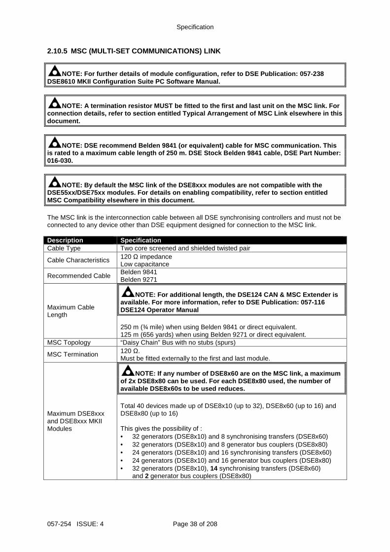
Specification
057-254 ISSUE: 4 Page 38 of 208
2.10.5 MSC (MULTI-SET COMMUNICATIONS) LINK
NOTE: For further details of module configuration, refer to DSE Publication: 057-238 DSE8610 MKII Configuration Suite PC Software Manual .
NOTE: A termination resistor MUST be fitted to the first and last unit on the MSC link. For connection details, refer to section entitled Typical Arrangement of MSC Link elsewhere in this document.
NOTE: DSE recommend Belden 9841 (or equivalent) cab le for MSC communication. This is rated to a maximum cable length of 250 m. DSE St ock Belden 9841 cable, DSE Part Number: 016-030.
NOTE: By default the MSC link of the DSE8xxx module s are not compatible with the DSE55xx/DSE75xx modules. For details on enabling co mpatibility, refer to section entitled MSC Compatibility elsewhere in this document. The MSC link is the interconnection cable between all DSE synchronising controllers and must not be connected to any device other than DSE equipment designed for connection to the MSC link. Description Specification Cable Type Two core screened and shielded twisted pair
Cable Characteristics 120 Ω impedance Low capacitance
Recommended Cable Belden 9841 Belden 9271
Maximum Cable Length
NOTE: For additional length, the DSE124 CAN & MSC E xtender is available. For more information, refer to DSE Publi cation: 057-116 DSE124 Operator Manual 250 m (¾ mile) when using Belden 9841 or direct equivalent. 125 m (656 yards) when using Belden 9271 or direct equivalent.
MSC Topology “Daisy Chain” Bus with no stubs (spurs)
MSC Termination 120 Ω. Must be fitted externally to the first and last module.
Maximum DSE8xxx and DSE8xxx MKII Modules
NOTE: If any number of DSE8x60 are on the MSC link, a maximum of 2x DSE8x80 can be used. For each DSE8x80 used, t he number of available DSE8x60s to be used reduces. Total 40 devices made up of DSE8x10 (up to 32), DSE8x60 (up to 16) and DSE8x80 (up to 16) This gives the possibility of : • 32 generators (DSE8x10) and 8 synchronising transfers (DSE8x60) • 32 generators (DSE8x10) and 8 generator bus couplers (DSE8x80) • 24 generators (DSE8x10) and 16 synchronising transfers (DSE8x60) • 24 generators (DSE8x10) and 16 generator bus couplers (DSE8x80) • 32 generators (DSE8x10), 14 synchronising transfers (DSE8x60)
and 2 generator bus couplers (DSE8x80)
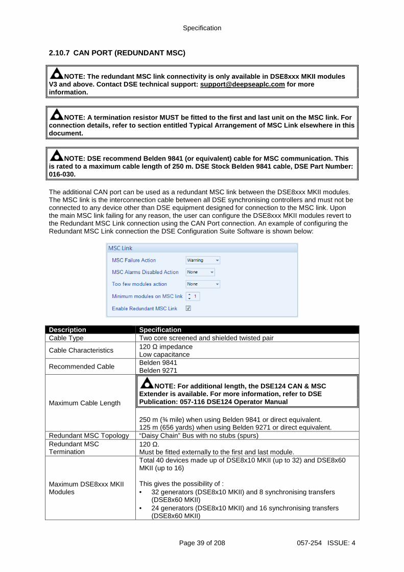
Specification
Page 39 of 208 057-254 ISSUE: 4
2.10.7 CAN PORT (REDUNDANT MSC)
NOTE: The redundant MSC link connectivity is only a vailable in DSE8xxx MKII modules V3 and above. Contact DSE technical support: suppor [email protected] for more information.
NOTE: A termination resistor MUST be fitted to the first and last unit on the MSC link. For connection details, refer to section entitled Typical Arrangement of MSC Link elsewhere in this document.
NOTE: DSE recommend Belden 9841 (or equivalent) cab le for MSC communication. This is rated to a maximum cable length of 250 m. DSE St ock Belden 9841 cable, DSE Part Number: 016-030. The additional CAN port can be used as a redundant MSC link between the DSE8xxx MKII modules. The MSC link is the interconnection cable between all DSE synchronising controllers and must not be connected to any device other than DSE equipment designed for connection to the MSC link. Upon the main MSC link failing for any reason, the user can configure the DSE8xxx MKII modules revert to the Redundant MSC Link connection using the CAN Port connection. An example of configuring the Redundant MSC Link connection the DSE Configuration Suite Software is shown below:
Description Specification Cable Type Two core screened and shielded twisted pair
Cable Characteristics 120 Ω impedance Low capacitance
Recommended Cable Belden 9841 Belden 9271
Maximum Cable Length
NOTE: For additional length, the DSE124 CAN & MSC Extender is available. For more information, refer to DSE Publication: 057-116 DSE124 Operator Manual 250 m (¾ mile) when using Belden 9841 or direct equivalent. 125 m (656 yards) when using Belden 9271 or direct equivalent.
Redundant MSC Topology “Daisy Chain” Bus with no stubs (spurs) Redundant MSC Termination
120 Ω. Must be fitted externally to the first and last module.
Maximum DSE8xxx MKII Modules
Total 40 devices made up of DSE8x10 MKII (up to 32) and DSE8x60 MKII (up to 16) This gives the possibility of : • 32 generators (DSE8x10 MKII) and 8 synchronising transfers
(DSE8x60 MKII) • 24 generators (DSE8x10 MKII) and 16 synchronising transfers
(DSE8x60 MKII)
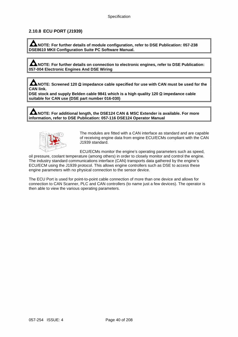
Specification
057-254 ISSUE: 4 Page 40 of 208
2.10.8 ECU PORT (J1939)
NOTE: For further details of module configuration, refer to DSE Publication: 057-238 DSE8610 MKII Configuration Suite PC Software Manual .
NOTE: For further details on connection to electron ic engines, refer to DSE Publication: 057-004 Electronic Engines And DSE Wiring
NOTE: Screened 120 ΩΩΩΩ impedance cable specified for use with CAN must be used for the CAN link. DSE stock and supply Belden cable 9841 which is a h igh quality 120 ΩΩΩΩ impedance cable suitable for CAN use (DSE part number 016-030)
NOTE: For additional length, the DSE124 CAN & MSC E xtender is available. For more information, refer to DSE Publication: 057-116 DSE124 Operator Manual
The modules are fitted with a CAN interface as standard and are capable of receiving engine data from engine ECU/ECMs compliant with the CAN J1939 standard. ECU/ECMs monitor the engine’s operating parameters such as speed,
oil pressure, coolant temperature (among others) in order to closely monitor and control the engine. The industry standard communications interface (CAN) transports data gathered by the engine’s ECU/ECM using the J1939 protocol. This allows engine controllers such as DSE to access these engine parameters with no physical connection to the sensor device. The ECU Port is used for point-to-point cable connection of more than one device and allows for connection to CAN Scanner, PLC and CAN controllers (to name just a few devices). The operator is then able to view the various operating parameters.
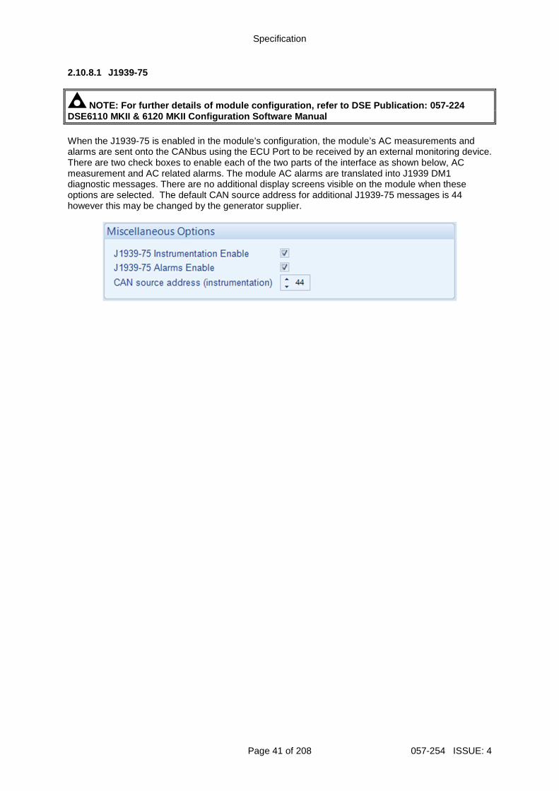
Specification
Page 41 of 208 057-254 ISSUE: 4
2.10.8.1 J1939-75
NOTE: For further details of module configuration, refer to DSE Publication: 057-224 DSE6110 MKII & 6120 MKII Configuration Software Man ual When the J1939-75 is enabled in the module’s configuration, the module’s AC measurements and alarms are sent onto the CANbus using the ECU Port to be received by an external monitoring device. There are two check boxes to enable each of the two parts of the interface as shown below, AC measurement and AC related alarms. The module AC alarms are translated into J1939 DM1 diagnostic messages. There are no additional display screens visible on the module when these options are selected. The default CAN source address for additional J1939-75 messages is 44 however this may be changed by the generator supplier.
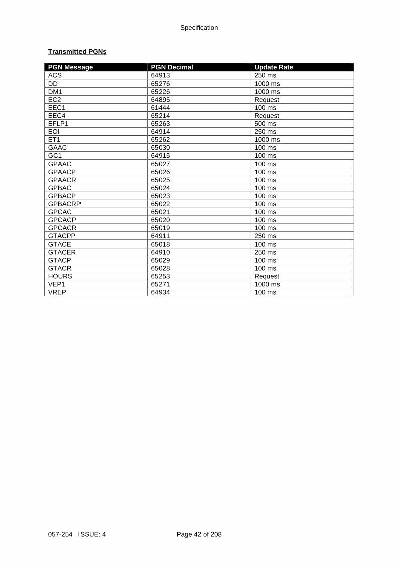
Specification
057-254 ISSUE: 4 Page 42 of 208
Transmitted PGNs PGN Message PGN Decimal Update Rate ACS 64913 250 ms DD 65276 1000 ms DM1 65226 1000 ms EC2 64895 Request EEC1 61444 100 ms EEC4 65214 Request EFLP1 65263 500 ms EOI 64914 250 ms ET1 65262 1000 ms GAAC 65030 100 ms GC1 64915 100 ms GPAAC 65027 100 ms GPAACP 65026 100 ms GPAACR 65025 100 ms GPBAC 65024 100 ms GPBACP 65023 100 ms GPBACRP 65022 100 ms GPCAC 65021 100 ms GPCACP 65020 100 ms GPCACR 65019 100 ms GTACPP 64911 250 ms GTACE 65018 100 ms GTACER 64910 250 ms GTACP 65029 100 ms GTACR 65028 100 ms HOURS 65253 Request VEP1 65271 1000 ms VREP 64934 100 ms
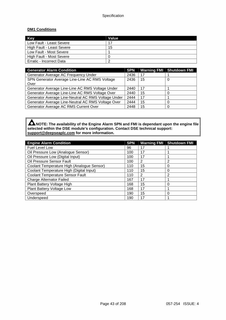
Specification
Page 43 of 208 057-254 ISSUE: 4
DM1 Conditions Key Value Low Fault - Least Severe 17 High Fault - Least Severe 15 Low Fault - Most Severe 1 High Fault - Most Severe 0 Erratic - Incorrect Data 2 Generator Alarm Condition SPN Warning FMI Shutdown FMI Generator Average AC Frequency Under 2436 17 1 SPN Generator Average Line-Line AC RMS Voltage Over
2436 15 0
Generator Average Line-Line AC RMS Voltage Under 2440 17 1 Generator Average Line-Line AC RMS Voltage Over 2440 15 0 Generator Average Line-Neutral AC RMS Voltage Under 2444 17 1 Generator Average Line-Neutral AC RMS Voltage Over 2444 15 0 Generator Average AC RMS Current Over 2448 15 0
NOTE: The availability of the Engine Alarm SPN and FMI is dependant upon the engine file selected within the DSE module’s configuration. Con tact DSE technical support: [email protected] for more information. Engine Alarm Condition SPN Warning FMI Shutdown FMI Fuel Level Low 96 17 1 Oil Pressure Low (Analogue Sensor) 100 17 1 Oil Pressure Low (Digital Input) 100 17 1 Oil Pressure Sensor Fault 100 2 2 Coolant Temperature High (Analogue Sensor) 110 15 0 Coolant Temperature High (Digital Input) 110 15 0 Coolant Temperature Sensor Fault 110 2 2 Charge Alternator Failed 167 17 1 Plant Battery Voltage High 168 15 0 Plant Battery Voltage Low 168 17 1 Overspeed 190 15 0 Underspeed 190 17 1
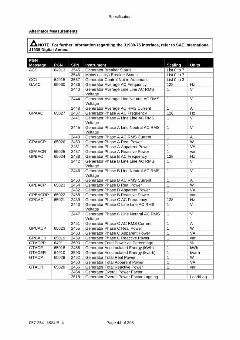
Specification
057-254 ISSUE: 4 Page 44 of 208
Alternator Measurements
NOTE: For further information regarding the J1939-7 5 interface, refer to SAE International J1939 Digital Annex. PGN Message PGN SPN Instrument Scaling Units ACS 64913 3545 Generator Breaker Status List 0 to 7 3546 Mains (Utility) Breaker Status List 0 to 7 GC1 64915 3567 Generator Control Not in Automatic List 0 to 3 GAAC 65030 2436 Generator Average AC Frequency 128 Hz 2440 Generator Average Line Line AC RMS
Voltage 1 V
2444 Generator Average Line Neutral AC RMS Voltage
1 V
2448 Generator Average AC RMS Current 1 A GPAAC 65027 2437 Generator Phase A AC Frequency 128 Hz 2441 Generator Phase A Line Line AC RMS
Voltage 1 V
2445 Generator Phase A Line Neutral AC RMS Voltage
1 V
2449 Generator Phase A AC RMS Current 1 A GPAACP 65026 2453 Generator Phase A Real Power 1 W 2461 Generator Phase A Apparent Power 1 VA GPAACR 65025 2457 Generator Phase A Reactive Power 1 var GPBAC 65024 2438 Generator Phase B AC Frequency 128 Hz 2442 Generator Phase B Line Line AC RMS
Voltage 1 V
2446 Generator Phase B Line Neutral AC RMS Voltage
1 V
2450 Generator Phase B AC RMS Current 1 A GPBACP 65023 2454 Generator Phase B Real Power 1 W 2462 Generator Phase B Apparent Power 1 VA GPBACRP 65022 2458 Generator Phase B Reactive Power 1 var GPCAC 65021 2439 Generator Phase C AC Frequency 128 Hz 2443 Generator Phase C Line Line AC RMS
Voltage 1 V
2447 Generator Phase C Line Neutral AC RMS Voltage
1 V
2451 Generator Phase C AC RMS Current 1 A GPCACP 65023 2455 Generator Phase C Real Power 1 W 2463 Generator Phase C Apparent Power 1 VA GPCACR 65019 2459 Generator Phase C Reactive Power 1 var GTACPP 64911 3590 Generator Total Power as Percentage 1 % GTACE 65018 2468 Generator Accumulated Energy (kWh) 1 kWh GTACER 64910 3593 Generator Accumulated Energy (kvarh) 1 kvarh GTACP 65029 2452 Generator Total Real Power 1 W 2460 Generator Total Apparent Power 1 VA GTACR 65028 2456 Generator Total Reactive Power 1 var 2464 Generator Overall Power Factor 2518 Generator Overall Power Factor Lagging Lead/Lag
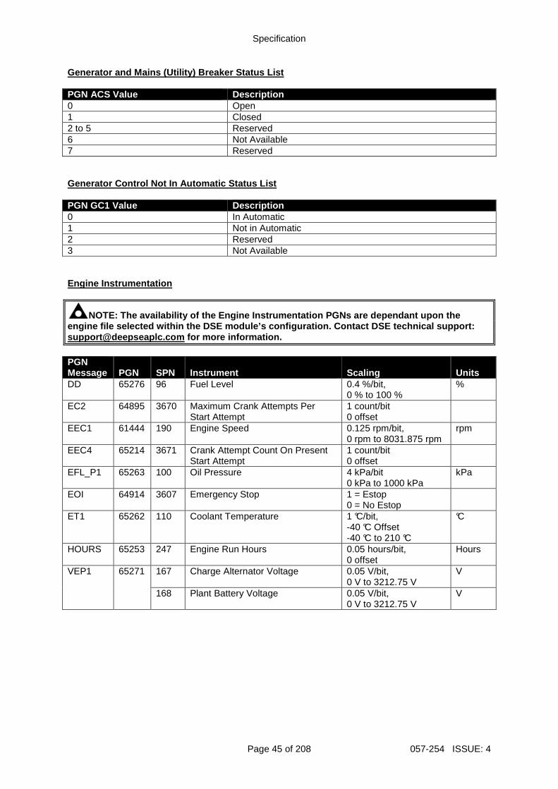
Specification
Page 45 of 208 057-254 ISSUE: 4
Generator and Mains (Utility) Breaker Status List PGN ACS Value Description 0 Open 1 Closed 2 to 5 Reserved 6 Not Available 7 Reserved Generator Control Not In Automatic Status List PGN GC1 Value Description 0 In Automatic 1 Not in Automatic 2 Reserved 3 Not Available Engine Instrumentation
NOTE: The availability of the Engine Instrumentatio n PGNs are dependant upon the engine file selected within the DSE module’s config uration. Contact DSE technical support: [email protected] for more information. PGN Message PGN SPN Instrument Scaling Units DD
65276 96 Fuel Level 0.4 %/bit, 0 % to 100 %
%
EC2 64895 3670 Maximum Crank Attempts Per Start Attempt
1 count/bit 0 offset
EEC1 61444 190 Engine Speed 0.125 rpm/bit, 0 rpm to 8031.875 rpm
rpm
EEC4 65214 3671 Crank Attempt Count On Present Start Attempt
1 count/bit 0 offset
EFL_P1 65263 100 Oil Pressure 4 kPa/bit 0 kPa to 1000 kPa
kPa
EOI 64914 3607 Emergency Stop 1 = Estop 0 = No Estop
ET1 65262 110 Coolant Temperature 1 °C/bit, -40 °C Offset -40 °C to 210 °C
°C
HOURS 65253 247 Engine Run Hours 0.05 hours/bit, 0 offset
Hours
VEP1 65271 167 Charge Alternator Voltage 0.05 V/bit, 0 V to 3212.75 V
V
168 Plant Battery Voltage 0.05 V/bit, 0 V to 3212.75 V
V
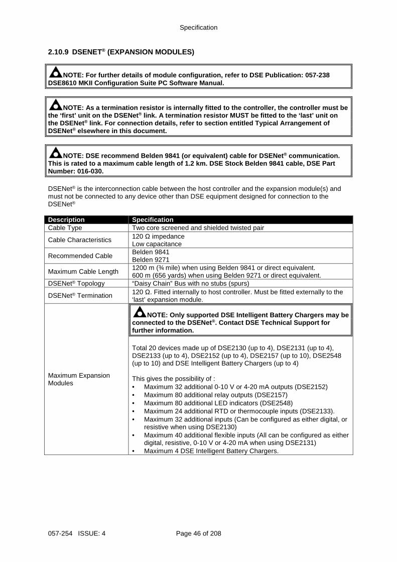
Specification
057-254 ISSUE: 4 Page 46 of 208
2.10.9 DSENET® (EXPANSION MODULES)
NOTE: For further details of module configuration, refer to DSE Publication: 057-238 DSE8610 MKII Configuration Suite PC Software Manual .
NOTE: As a termination resistor is internally fitte d to the controller, the controller must be the ‘first’ unit on the DSENet ® link. A termination resistor MUST be fitted to the ‘last’ unit on the DSENet ® link. For connection details, refer to section ent itled Typical Arrangement of DSENet® elsewhere in this document.
NOTE: DSE recommend Belden 9841 (or equivalent) cab le for DSENet ® communication. This is rated to a maximum cable length of 1.2 km. DSE Stock Belden 9841 cable, DSE Part Number: 016-030. DSENet® is the interconnection cable between the host controller and the expansion module(s) and must not be connected to any device other than DSE equipment designed for connection to the DSENet® Description Specification Cable Type Two core screened and shielded twisted pair
Cable Characteristics 120 Ω impedance Low capacitance
Recommended Cable Belden 9841 Belden 9271
Maximum Cable Length 1200 m (¾ mile) when using Belden 9841 or direct equivalent. 600 m (656 yards) when using Belden 9271 or direct equivalent.
DSENet® Topology “Daisy Chain” Bus with no stubs (spurs)
DSENet® Termination 120 Ω. Fitted internally to host controller. Must be fitted externally to the ‘last’ expansion module.
Maximum Expansion Modules
NOTE: Only supported DSE Intelligent Battery Charge rs may be connected to the DSENet ®. Contact DSE Technical Support for further information. Total 20 devices made up of DSE2130 (up to 4), DSE2131 (up to 4), DSE2133 (up to 4), DSE2152 (up to 4), DSE2157 (up to 10), DSE2548 (up to 10) and DSE Intelligent Battery Chargers (up to 4) This gives the possibility of : • Maximum 32 additional 0-10 V or 4-20 mA outputs (DSE2152) • Maximum 80 additional relay outputs (DSE2157) • Maximum 80 additional LED indicators (DSE2548) • Maximum 24 additional RTD or thermocouple inputs (DSE2133). • Maximum 32 additional inputs (Can be configured as either digital, or
resistive when using DSE2130) • Maximum 40 additional flexible inputs (All can be configured as either
digital, resistive, 0-10 V or 4-20 mA when using DSE2131) • Maximum 4 DSE Intelligent Battery Chargers.
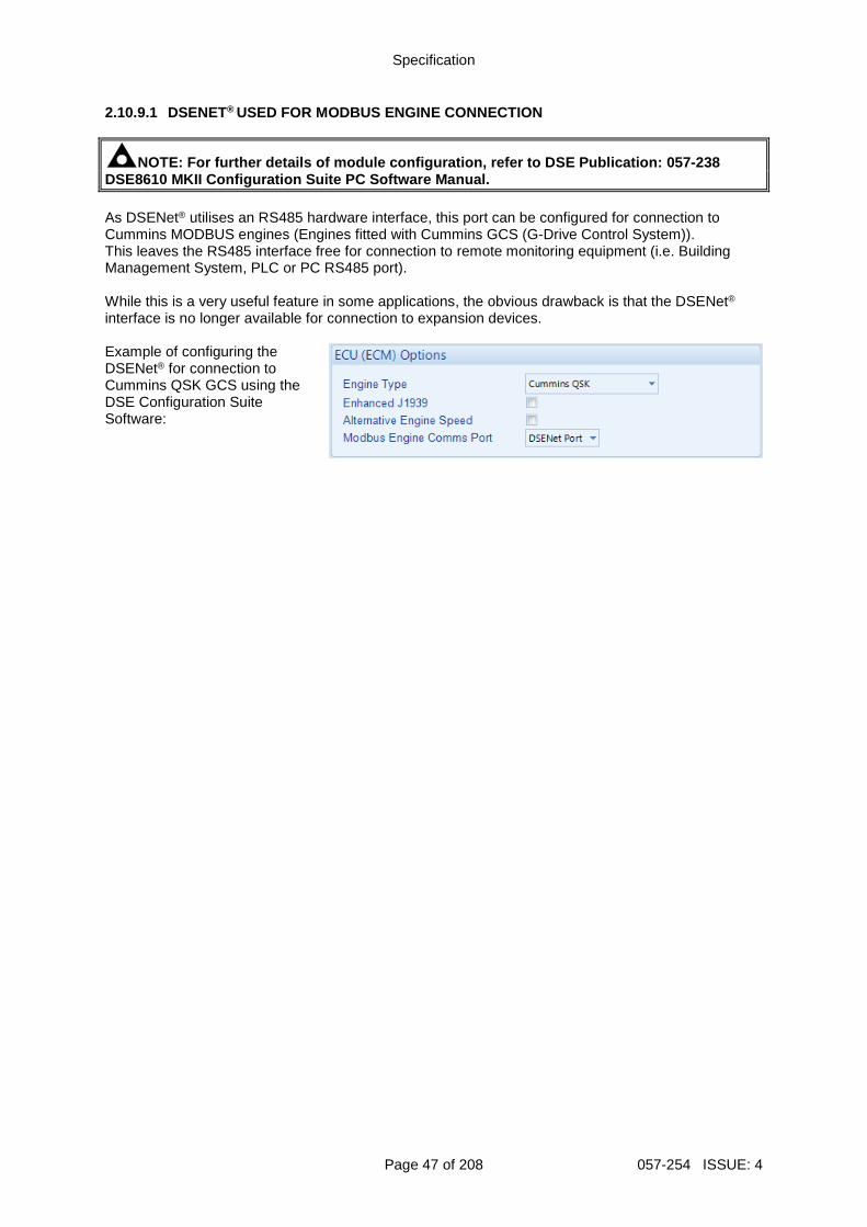
Specification
Page 47 of 208 057-254 ISSUE: 4
2.10.9.1 DSENET® USED FOR MODBUS ENGINE CONNECTION
NOTE: For further details of module configuration, refer to DSE Publication: 057-238 DSE8610 MKII Configuration Suite PC Software Manual . As DSENet® utilises an RS485 hardware interface, this port can be configured for connection to Cummins MODBUS engines (Engines fitted with Cummins GCS (G-Drive Control System)). This leaves the RS485 interface free for connection to remote monitoring equipment (i.e. Building Management System, PLC or PC RS485 port). While this is a very useful feature in some applications, the obvious drawback is that the DSENet® interface is no longer available for connection to expansion devices. Example of configuring the DSENet® for connection to Cummins QSK GCS using the DSE Configuration Suite Software:
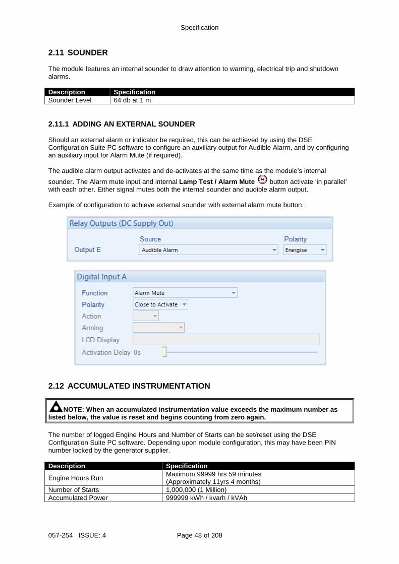
Specification
057-254 ISSUE: 4 Page 48 of 208
2.11 SOUNDER The module features an internal sounder to draw attention to warning, electrical trip and shutdown alarms. Description Specification Sounder Level 64 db at 1 m 2.11.1 ADDING AN EXTERNAL SOUNDER Should an external alarm or indicator be required, this can be achieved by using the DSE Configuration Suite PC software to configure an auxiliary output for Audible Alarm, and by configuring an auxiliary input for Alarm Mute (if required). The audible alarm output activates and de-activates at the same time as the module’s internal
sounder. The Alarm mute input and internal Lamp Test / Alarm Mute button activate ‘in parallel’ with each other. Either signal mutes both the internal sounder and audible alarm output. Example of configuration to achieve external sounder with external alarm mute button:
2.12 ACCUMULATED INSTRUMENTATION
NOTE: When an accumulated instrumentation value exc eeds the maximum number as listed below, the value is reset and begins countin g from zero again. The number of logged Engine Hours and Number of Starts can be set/reset using the DSE Configuration Suite PC software. Depending upon module configuration, this may have been PIN number locked by the generator supplier. Description Specification
Engine Hours Run Maximum 99999 hrs 59 minutes (Approximately 11yrs 4 months)
Number of Starts 1,000,000 (1 Million) Accumulated Power 999999 kWh / kvarh / kVAh
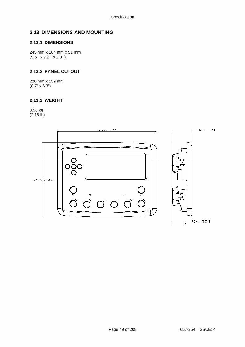
Specification
Page 49 of 208 057-254 ISSUE: 4
2.13 DIMENSIONS AND MOUNTING 2.13.1 DIMENSIONS 245 mm x 184 mm x 51 mm (9.6 ” x 7.2 ” x 2.0 ”) 2.13.2 PANEL CUTOUT 220 mm x 159 mm (8.7” x 6.3”) 2.13.3 WEIGHT 0.98 kg (2.16 lb)
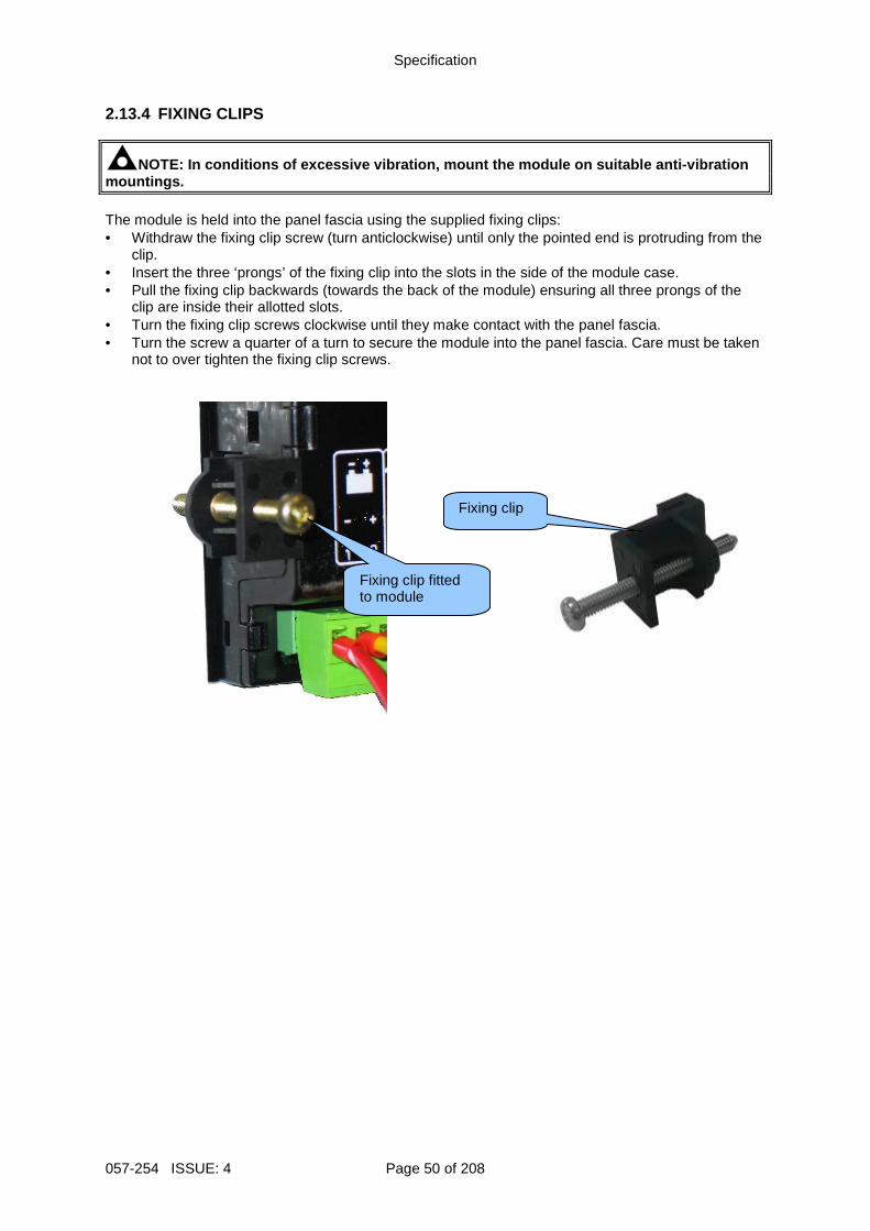
Specification
057-254 ISSUE: 4 Page 50 of 208
2.13.4 FIXING CLIPS
NOTE: In conditions of excessive vibration, mount t he module on suitable anti-vibration mountings. The module is held into the panel fascia using the supplied fixing clips: • Withdraw the fixing clip screw (turn anticlockwise) until only the pointed end is protruding from the
clip. • Insert the three ‘prongs’ of the fixing clip into the slots in the side of the module case. • Pull the fixing clip backwards (towards the back of the module) ensuring all three prongs of the
clip are inside their allotted slots. • Turn the fixing clip screws clockwise until they make contact with the panel fascia. • Turn the screw a quarter of a turn to secure the module into the panel fascia. Care must be taken
not to over tighten the fixing clip screws.
Fixing clip fitted to module
Fixing clip
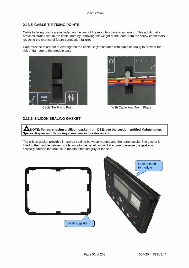
Specification
Page 51 of 208 057-254 ISSUE: 4
2.13.5 CABLE TIE FIXING POINTS Cable tie fixing points are included on the rear of the module’s case to aid wiring. This additionally provides strain relief to the cable loom by removing the weight of the loom from the screw connectors, reducing the chance of future connection failures. Care must be taken not to over tighten the cable tie (for instance with cable tie tools) to prevent the risk of damage to the module case.
Cable Tie Fixing Point With Cable And Tie In Place
2.13.6 SILICON SEALING GASKET
NOTE: For purchasing a silicon gasket from DSE, see the section entitled Maintenance, Spares, Repair and Servicing elsewhere in this docu ment. The silicon gasket provides improved sealing between module and the panel fascia. The gasket is fitted to the module before installation into the panel fascia. Take care to ensure the gasket is correctly fitted to the module to maintain the integrity of the seal.
Gasket fitted to module
Sealing gasket
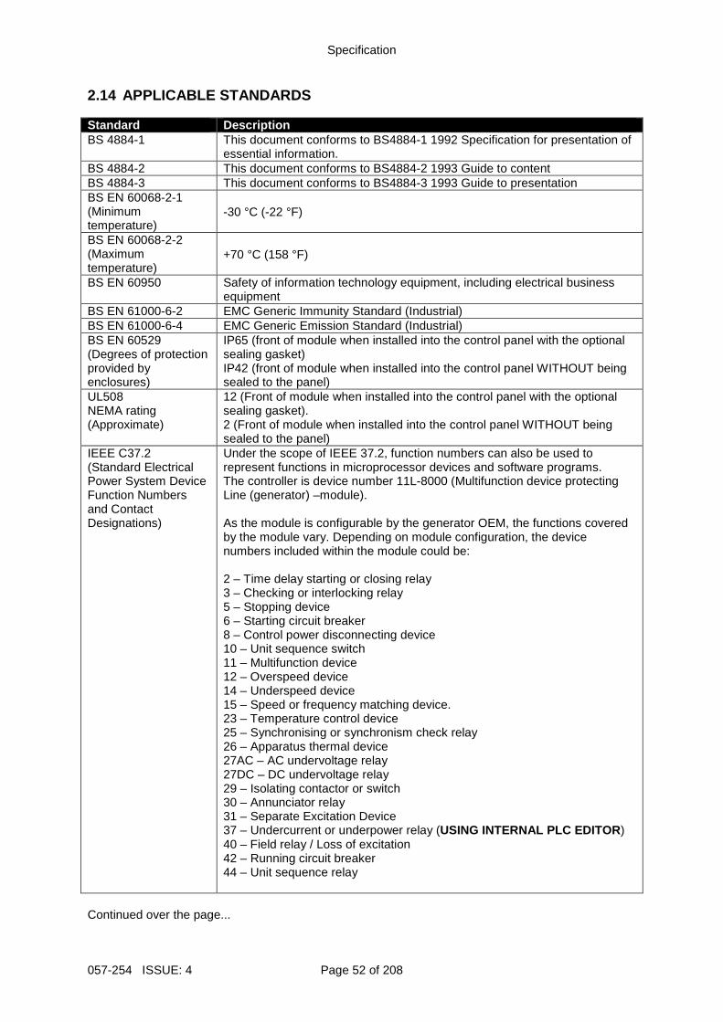
Specification
057-254 ISSUE: 4 Page 52 of 208
2.14 APPLICABLE STANDARDS Standard Description BS 4884-1 This document conforms to BS4884-1 1992 Specification for presentation of
essential information. BS 4884-2 This document conforms to BS4884-2 1993 Guide to content BS 4884-3 This document conforms to BS4884-3 1993 Guide to presentation BS EN 60068-2-1 (Minimum temperature)
-30 °C (-22 °F)
BS EN 60068-2-2 (Maximum temperature)
+70 °C (158 °F)
BS EN 60950 Safety of information technology equipment, including electrical business equipment
BS EN 61000-6-2 EMC Generic Immunity Standard (Industrial) BS EN 61000-6-4 EMC Generic Emission Standard (Industrial) BS EN 60529 (Degrees of protection provided by enclosures)
IP65 (front of module when installed into the control panel with the optional sealing gasket) IP42 (front of module when installed into the control panel WITHOUT being sealed to the panel)
UL508 NEMA rating (Approximate)
12 (Front of module when installed into the control panel with the optional sealing gasket). 2 (Front of module when installed into the control panel WITHOUT being sealed to the panel)
IEEE C37.2 (Standard Electrical Power System Device Function Numbers and Contact Designations)
Under the scope of IEEE 37.2, function numbers can also be used to represent functions in microprocessor devices and software programs. The controller is device number 11L-8000 (Multifunction device protecting Line (generator) –module). As the module is configurable by the generator OEM, the functions covered by the module vary. Depending on module configuration, the device numbers included within the module could be: 2 – Time delay starting or closing relay 3 – Checking or interlocking relay 5 – Stopping device 6 – Starting circuit breaker 8 – Control power disconnecting device 10 – Unit sequence switch 11 – Multifunction device 12 – Overspeed device 14 – Underspeed device 15 – Speed or frequency matching device. 23 – Temperature control device 25 – Synchronising or synchronism check relay 26 – Apparatus thermal device 27AC – AC undervoltage relay 27DC – DC undervoltage relay 29 – Isolating contactor or switch 30 – Annunciator relay 31 – Separate Excitation Device 37 – Undercurrent or underpower relay (USING INTERNAL PLC EDITOR ) 40 – Field relay / Loss of excitation 42 – Running circuit breaker 44 – Unit sequence relay
Continued over the page...
Specification
Page 53 of 208 057-254 ISSUE: 4
Standard Description IEEE C37.2 (Standard Electrical Power System Device Function Numbers and Contact Designations)
Continued… 46 – Reverse-phase or phase-balance current relay 48 – Incomplete sequence relay 49 – Machine or transformer thermal relay 50 – Instantaneous overcurrent relay 51 – AC time overcurrent relay 52 – AC circuit breaker 53 – Exciter or DC generator relay 54 – Turning gear engaging device 55 – Power factor relay (USING INTERNAL PLC EDITOR ) 59AC – AC overvoltage relay 59DC – DC overvoltage relay 62 – Time delay stopping or opening relay 63 – Pressure switch 71 – Level switch 74 – Alarm relay 78 – Phase-angle measuring relay 79 – Reclosing relay (USING INTERNAL PLC EDITOR ) 81 – Frequency relay 83 – Automatic selective control or transfer relay 86 – Lockout relay
In line with our policy of continual development, Deep Sea Electronics, reserve the right to change specification without notice.
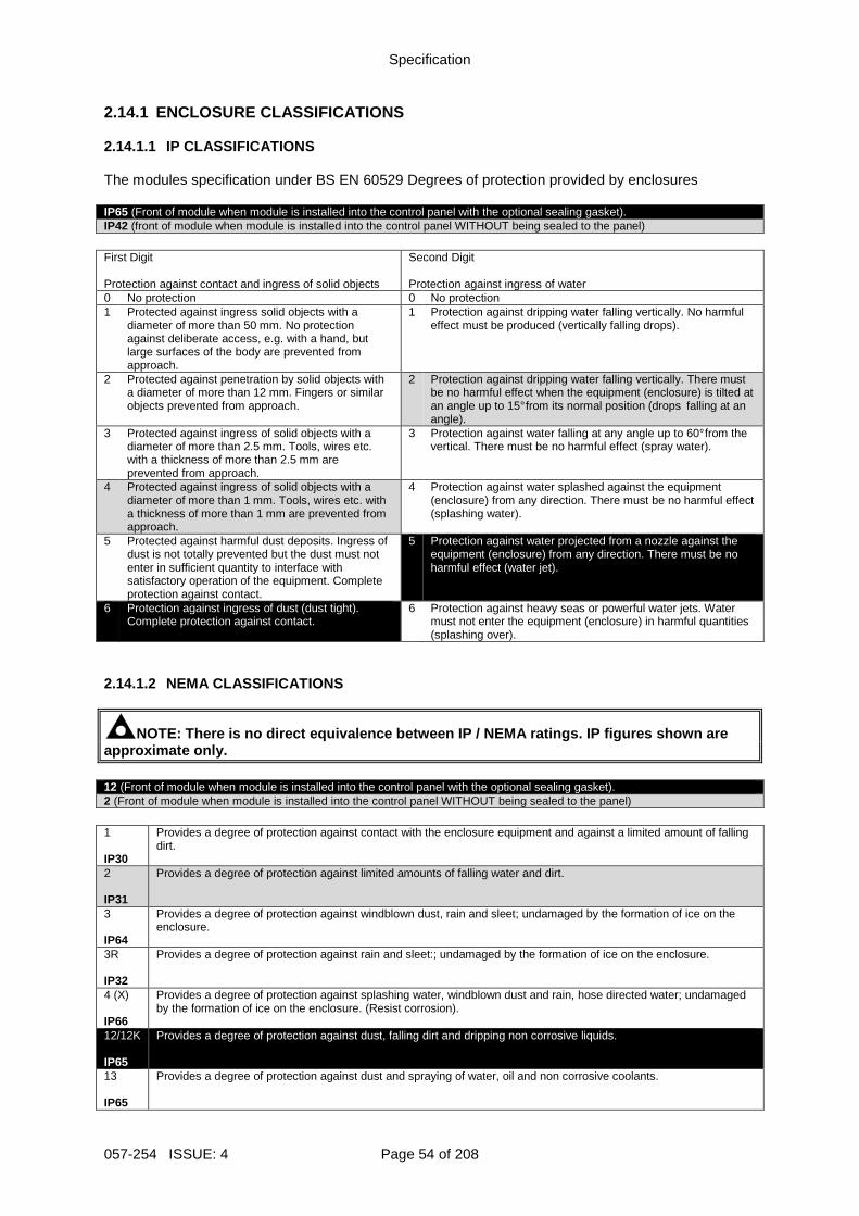
Specification
057-254 ISSUE: 4 Page 54 of 208
2.14.1 ENCLOSURE CLASSIFICATIONS 2.14.1.1 IP CLASSIFICATIONS The modules specification under BS EN 60529 Degrees of protection provided by enclosures IP65 (Front of module when module is installed into the control panel with the optional sealing gasket). IP42 (front of module when module is installed into the control panel WITHOUT being sealed to the panel)
First Digit
Second Digit
Protection against contact and ingress of solid objects Protection against ingress of water 0 No protection 0 No protection 1 Protected against ingress solid objects with a
diameter of more than 50 mm. No protection against deliberate access, e.g. with a hand, but large surfaces of the body are prevented from approach.
1 Protection against dripping water falling vertically. No harmful effect must be produced (vertically falling drops).
2 Protected against penetration by solid objects with a diameter of more than 12 mm. Fingers or similar objects prevented from approach.
2 Protection against dripping water falling vertically. There must be no harmful effect when the equipment (enclosure) is tilted at an angle up to 15° from its normal position (drops falling at an angle).
3 Protected against ingress of solid objects with a diameter of more than 2.5 mm. Tools, wires etc. with a thickness of more than 2.5 mm are prevented from approach.
3 Protection against water falling at any angle up to 60° from the vertical. There must be no harmful effect (spray water).
4 Protected against ingress of solid objects with a diameter of more than 1 mm. Tools, wires etc. with a thickness of more than 1 mm are prevented from approach.
4 Protection against water splashed against the equipment (enclosure) from any direction. There must be no harmful effect (splashing water).
5 Protected against harmful dust deposits. Ingress of dust is not totally prevented but the dust must not enter in sufficient quantity to interface with satisfactory operation of the equipment. Complete protection against contact.
5 Protection against water projected from a nozzle against the equipment (enclosure) from any direction. There must be no harmful effect (water jet).
6 Protection against ingress of dust (dust tight). Complete protection against contact.
6 Protection against heavy seas or powerful water jets. Water must not enter the equipment (enclosure) in harmful quantities (splashing over).
2.14.1.2 NEMA CLASSIFICATIONS
NOTE: There is no direct equivalence between IP / N EMA ratings. IP figures shown are approximate only. 12 (Front of module when module is installed into the control panel with the optional sealing gasket). 2 (Front of module when module is installed into the control panel WITHOUT being sealed to the panel)
1 IP30
Provides a degree of protection against contact with the enclosure equipment and against a limited amount of falling dirt.
2 IP31
Provides a degree of protection against limited amounts of falling water and dirt.
3 IP64
Provides a degree of protection against windblown dust, rain and sleet; undamaged by the formation of ice on the enclosure.
3R IP32
Provides a degree of protection against rain and sleet:; undamaged by the formation of ice on the enclosure.
4 (X) IP66
Provides a degree of protection against splashing water, windblown dust and rain, hose directed water; undamaged by the formation of ice on the enclosure. (Resist corrosion).
12/12K IP65
Provides a degree of protection against dust, falling dirt and dripping non corrosive liquids.
13 IP65
Provides a degree of protection against dust and spraying of water, oil and non corrosive coolants.
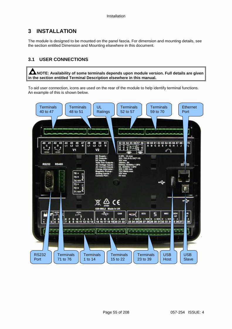
Installation
Page 55 of 208 057-254 ISSUE: 4
3 INSTALLATION The module is designed to be mounted on the panel fascia. For dimension and mounting details, see the section entitled Dimension and Mounting elsewhere in this document. 3.1 USER CONNECTIONS
NOTE: Availability of some terminals depends upon m odule version. Full details are given in the section entitled Terminal Description elsewhere in this manual. To aid user connection, icons are used on the rear of the module to help identify terminal functions. An example of this is shown below.
Terminals 1 to 14
Terminals 15 to 22
Terminals 52 to 57
USB Host
Terminals 48 to 51
UL Ratings
Terminals 23 to 39
Terminals 40 to 47
Terminals 59 to 70
RS232 Port
Terminals 71 to 76
USB Slave
Ethernet Port
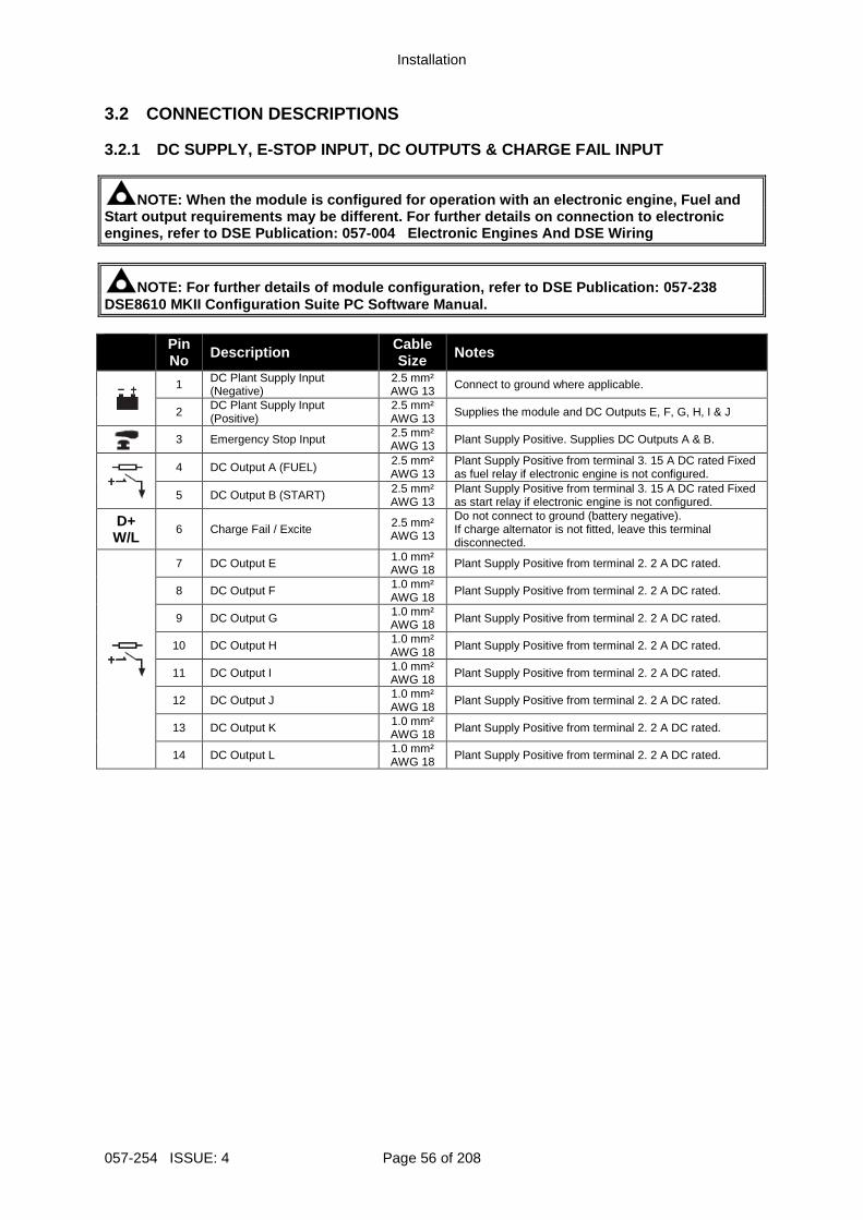
Installation
057-254 ISSUE: 4 Page 56 of 208
3.2 CONNECTION DESCRIPTIONS 3.2.1 DC SUPPLY, E-STOP INPUT, DC OUTPUTS & CHARGE FAIL INPUT
NOTE: When the module is configured for operation w ith an electronic engine, Fuel and Start output requirements may be different. For further details on connection to electronic engines, refer to DSE Publication: 057-004 Electronic Engines And DSE Wiring
NOTE: For further details of module configuration, refer to DSE Publication: 057-238 DSE8610 MKII Configuration Suite PC Software Manual . Pin
No Description Cable Size Notes
1 DC Plant Supply Input (Negative)
2.5 mm² AWG 13 Connect to ground where applicable.
2 DC Plant Supply Input (Positive)
2.5 mm² AWG 13 Supplies the module and DC Outputs E, F, G, H, I & J
3 Emergency Stop Input 2.5 mm²
AWG 13 Plant Supply Positive. Supplies DC Outputs A & B.
4 DC Output A (FUEL) 2.5 mm² AWG 13
Plant Supply Positive from terminal 3. 15 A DC rated Fixed as fuel relay if electronic engine is not configured.
5 DC Output B (START) 2.5 mm² AWG 13
Plant Supply Positive from terminal 3. 15 A DC rated Fixed as start relay if electronic engine is not configured.
D+ W/L
6 Charge Fail / Excite 2.5 mm² AWG 13
Do not connect to ground (battery negative). If charge alternator is not fitted, leave this terminal disconnected.
7 DC Output E 1.0 mm² AWG 18 Plant Supply Positive from terminal 2. 2 A DC rated.
8 DC Output F 1.0 mm² AWG 18
Plant Supply Positive from terminal 2. 2 A DC rated.
9 DC Output G 1.0 mm² AWG 18 Plant Supply Positive from terminal 2. 2 A DC rated.
10 DC Output H 1.0 mm² AWG 18
Plant Supply Positive from terminal 2. 2 A DC rated.
11 DC Output I 1.0 mm² AWG 18 Plant Supply Positive from terminal 2. 2 A DC rated.
12 DC Output J 1.0 mm² AWG 18
Plant Supply Positive from terminal 2. 2 A DC rated.
13 DC Output K 1.0 mm² AWG 18 Plant Supply Positive from terminal 2. 2 A DC rated.
14 DC Output L 1.0 mm² AWG 18
Plant Supply Positive from terminal 2. 2 A DC rated.
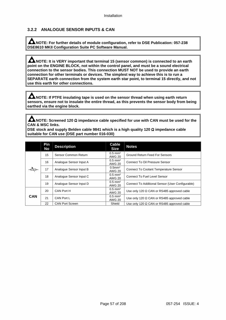
Installation
Page 57 of 208 057-254 ISSUE: 4
3.2.2 ANALOGUE SENSOR INPUTS & CAN
NOTE: For further details of module configuration, refer to DSE Publication: 057-238 DSE8610 MKII Configuration Suite PC Software Manual .
NOTE: It is VERY important that terminal 15 (sensor common) is connected to an earth point on the ENGINE BLOCK, not within the control p anel, and must be a sound electrical connection to the sensor bodies. This connection MU ST NOT be used to provide an earth connection for other terminals or devices. The simp lest way to achieve this is to run a SEPARATE earth connection from the system earth sta r point, to terminal 15 directly, and not use this earth for other connections.
NOTE: If PTFE insulating tape is used on the sensor thread when using earth return sensors, ensure not to insulate the entire thread, as this prevents the sensor body from being earthed via the engine block.
NOTE: Screened 120 ΩΩΩΩ impedance cable specified for use with CAN must be used for the CAN & MSC links. DSE stock and supply Belden cable 9841 which is a h igh quality 120 ΩΩΩΩ impedance cable suitable for CAN use (DSE part number 016-030) Pin
No Description Cable Size Notes
15 Sensor Common Return 0.5 mm² AWG 20 Ground Return Feed For Sensors
16 Analogue Sensor Input A 0.5 mm² AWG 20 Connect To Oil Pressure Sensor
17 Analogue Sensor Input B 0.5mm² AWG 20 Connect To Coolant Temperature Sensor
18 Analogue Sensor Input C 0.5 mm² AWG 20 Connect To Fuel Level Sensor
19 Analogue Sensor Input D 0.5 mm² AWG 20 Connect To Additional Sensor (User Configurable)
CAN
20 CAN Port H 0.5 mm² AWG 20 Use only 120 Ω CAN or RS485 approved cable
21 CAN Port L 0.5 mm² AWG 20 Use only 120 Ω CAN or RS485 approved cable
22 CAN Port Screen Shield Use only 120 Ω CAN or RS485 approved cable
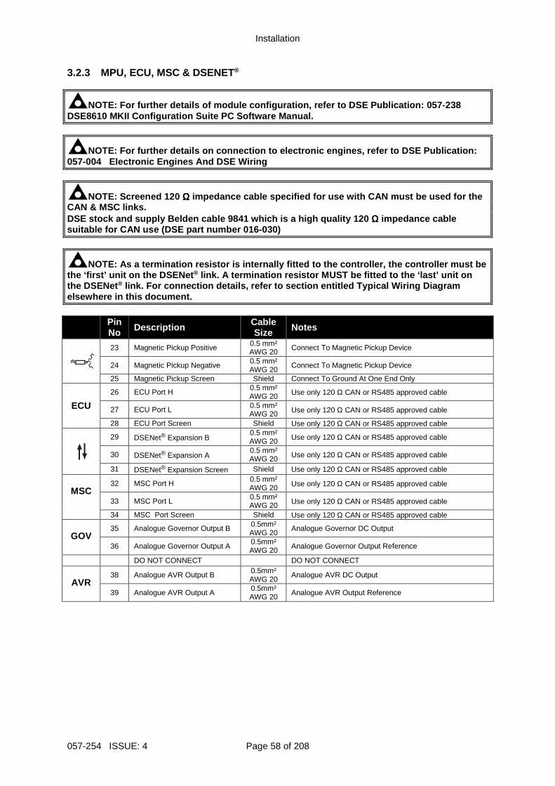
Installation
057-254 ISSUE: 4 Page 58 of 208
3.2.3 MPU, ECU, MSC & DSENET®
NOTE: For further details of module configuration, refer to DSE Publication: 057-238 DSE8610 MKII Configuration Suite PC Software Manual .
NOTE: For further details on connection to electron ic engines, refer to DSE Publication: 057-004 Electronic Engines And DSE Wiring
NOTE: Screened 120 ΩΩΩΩ impedance cable specified for use with CAN must be used for the CAN & MSC links. DSE stock and supply Belden cable 9841 which is a h igh quality 120 ΩΩΩΩ impedance cable suitable for CAN use (DSE part number 016-030)
NOTE: As a termination resistor is internally fitte d to the controller, the controller must be the ‘first’ unit on the DSENet ® link. A termination resistor MUST be fitted to the ‘last’ unit on the DSENet ® link. For connection details, refer to section ent itled Typical Wiring Diagram elsewhere in this document. Pin
No Description Cable Size Notes
23 Magnetic Pickup Positive 0.5 mm² AWG 20 Connect To Magnetic Pickup Device
24 Magnetic Pickup Negative 0.5 mm² AWG 20
Connect To Magnetic Pickup Device
25 Magnetic Pickup Screen Shield Connect To Ground At One End Only
ECU
26 ECU Port H 0.5 mm² AWG 20 Use only 120 Ω CAN or RS485 approved cable
27 ECU Port L 0.5 mm² AWG 20 Use only 120 Ω CAN or RS485 approved cable
28 ECU Port Screen Shield Use only 120 Ω CAN or RS485 approved cable
29 DSENet® Expansion B 0.5 mm² AWG 20 Use only 120 Ω CAN or RS485 approved cable
30 DSENet® Expansion A 0.5 mm² AWG 20 Use only 120 Ω CAN or RS485 approved cable
31 DSENet® Expansion Screen Shield Use only 120 Ω CAN or RS485 approved cable
MSC
32 MSC Port H 0.5 mm² AWG 20 Use only 120 Ω CAN or RS485 approved cable
33 MSC Port L 0.5 mm² AWG 20 Use only 120 Ω CAN or RS485 approved cable
34 MSC Port Screen Shield Use only 120 Ω CAN or RS485 approved cable
GOV 35 Analogue Governor Output B 0.5mm²
AWG 20 Analogue Governor DC Output
36 Analogue Governor Output A 0.5mm² AWG 20 Analogue Governor Output Reference
DO NOT CONNECT DO NOT CONNECT
AVR
38 Analogue AVR Output B 0.5mm² AWG 20
Analogue AVR DC Output
39 Analogue AVR Output A 0.5mm² AWG 20 Analogue AVR Output Reference
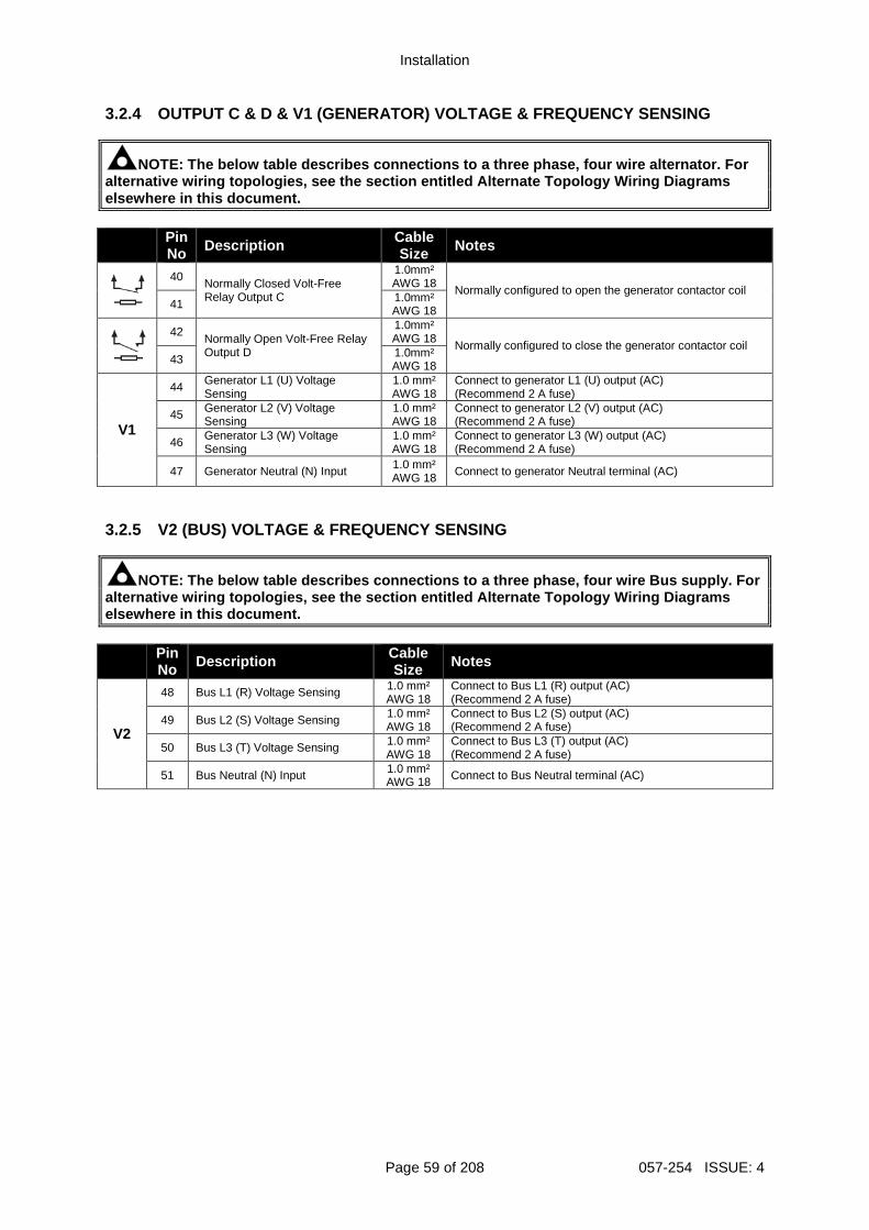
Installation
Page 59 of 208 057-254 ISSUE: 4
3.2.4 OUTPUT C & D & V1 (GENERATOR) VOLTAGE & FREQU ENCY SENSING
NOTE: The below table describes connections to a th ree phase, four wire alternator. For alternative wiring topologies, see the section enti tled Alternate Topology Wiring Diagrams elsewhere in this document. Pin
No Description Cable Size Notes
40 Normally Closed Volt-Free Relay Output C
1.0mm² AWG 18
Normally configured to open the generator contactor coil 41 1.0mm²
AWG 18
42 Normally Open Volt-Free Relay Output D
1.0mm² AWG 18
Normally configured to close the generator contactor coil 43 1.0mm²
AWG 18
V1
44 Generator L1 (U) Voltage Sensing
1.0 mm² AWG 18
Connect to generator L1 (U) output (AC) (Recommend 2 A fuse)
45 Generator L2 (V) Voltage Sensing
1.0 mm² AWG 18
Connect to generator L2 (V) output (AC) (Recommend 2 A fuse)
46 Generator L3 (W) Voltage Sensing
1.0 mm² AWG 18
Connect to generator L3 (W) output (AC) (Recommend 2 A fuse)
47 Generator Neutral (N) Input 1.0 mm² AWG 18 Connect to generator Neutral terminal (AC)
3.2.5 V2 (BUS) VOLTAGE & FREQUENCY SENSING
NOTE: The below table describes connections to a th ree phase, four wire Bus supply. For alternative wiring topologies, see the section enti tled Alternate Topology Wiring Diagrams elsewhere in this document.
Pin No Description Cable
Size Notes
V2
48 Bus L1 (R) Voltage Sensing 1.0 mm² AWG 18
Connect to Bus L1 (R) output (AC) (Recommend 2 A fuse)
49 Bus L2 (S) Voltage Sensing 1.0 mm² AWG 18
Connect to Bus L2 (S) output (AC) (Recommend 2 A fuse)
50 Bus L3 (T) Voltage Sensing 1.0 mm² AWG 18
Connect to Bus L3 (T) output (AC) (Recommend 2 A fuse)
51 Bus Neutral (N) Input 1.0 mm² AWG 18 Connect to Bus Neutral terminal (AC)
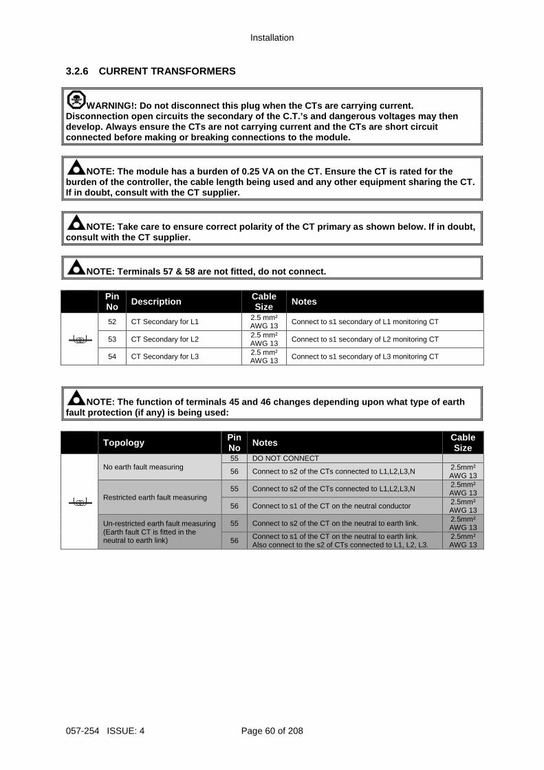
Installation
057-254 ISSUE: 4 Page 60 of 208
3.2.6 CURRENT TRANSFORMERS
WARNING!: Do not disconnect this plug when the CTs are carrying current. Disconnection open circuits the secondary of the C. T.’s and dangerous voltages may then develop. Always ensure the CTs are not carrying cur rent and the CTs are short circuit connected before making or breaking connections to the module.
NOTE: The module has a burden of 0.25 VA on the CT. Ensure the CT is rated for the burden of the controller, the cable length being us ed and any other equipment sharing the CT. If in doubt, consult with the CT supplier.
NOTE: Take care to ensure correct polarity of the C T primary as shown below. If in doubt, consult with the CT supplier.
NOTE: Terminals 57 & 58 are not fitted, do not conn ect. Pin
No Description Cable Size Notes
52 CT Secondary for L1 2.5 mm² AWG 13 Connect to s1 secondary of L1 monitoring CT
53 CT Secondary for L2 2.5 mm² AWG 13 Connect to s1 secondary of L2 monitoring CT
54 CT Secondary for L3 2.5 mm² AWG 13 Connect to s1 secondary of L3 monitoring CT
NOTE: The function of terminals 45 and 46 changes d epending upon what type of earth fault protection (if any) is being used:
Topology Pin No Notes Cable
Size
No earth fault measuring 55 DO NOT CONNECT
56 Connect to s2 of the CTs connected to L1,L2,L3,N 2.5mm² AWG 13
Restricted earth fault measuring 55 Connect to s2 of the CTs connected to L1,L2,L3,N 2.5mm²
AWG 13
56 Connect to s1 of the CT on the neutral conductor 2.5mm² AWG 13
Un-restricted earth fault measuring (Earth fault CT is fitted in the neutral to earth link)
55 Connect to s2 of the CT on the neutral to earth link. 2.5mm² AWG 13
56 Connect to s1 of the CT on the neutral to earth link. Also connect to the s2 of CTs connected to L1, L2, L3.
2.5mm² AWG 13
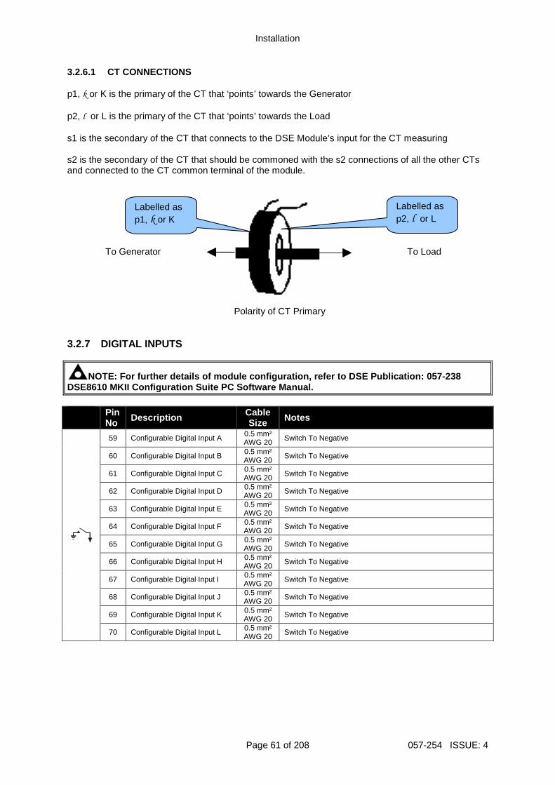
Installation
Page 61 of 208 057-254 ISSUE: 4
3.2.6.1 CT CONNECTIONS p1, k or K is the primary of the CT that ‘points’ towards the Generator p2, l or L is the primary of the CT that ‘points’ towards the Load s1 is the secondary of the CT that connects to the DSE Module’s input for the CT measuring s2 is the secondary of the CT that should be commoned with the s2 connections of all the other CTs and connected to the CT common terminal of the module.
To Generator
To Load
Polarity of CT Primary
3.2.7 DIGITAL INPUTS
NOTE: For further details of module configuration, refer to DSE Publication: 057-238 DSE8610 MKII Configuration Suite PC Software Manual . Pin
No Description Cable Size Notes
59 Configurable Digital Input A 0.5 mm² AWG 20 Switch To Negative
60 Configurable Digital Input B 0.5 mm² AWG 20
Switch To Negative
61 Configurable Digital Input C 0.5 mm² AWG 20 Switch To Negative
62 Configurable Digital Input D 0.5 mm² AWG 20
Switch To Negative
63 Configurable Digital Input E 0.5 mm² AWG 20 Switch To Negative
64 Configurable Digital Input F 0.5 mm² AWG 20
Switch To Negative
65 Configurable Digital Input G 0.5 mm² AWG 20 Switch To Negative
66 Configurable Digital Input H 0.5 mm² AWG 20
Switch To Negative
67 Configurable Digital Input I 0.5 mm² AWG 20 Switch To Negative
68 Configurable Digital Input J 0.5 mm² AWG 20
Switch To Negative
69 Configurable Digital Input K 0.5 mm² AWG 20 Switch To Negative
70 Configurable Digital Input L 0.5 mm² AWG 20
Switch To Negative
Labelled as p1, k or K
Labelled as p2, l or L
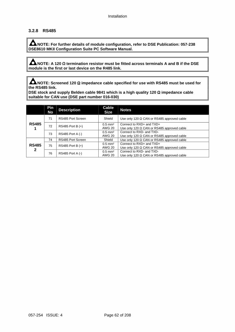
Installation
057-254 ISSUE: 4 Page 62 of 208
3.2.8 RS485
NOTE: For further details of module configuration, refer to DSE Publication: 057-238 DSE8610 MKII Configuration Suite PC Software Manual .
NOTE: A 120 Ω termination resistor must be fitted across termina ls A and B if the DSE module is the first or last device on the R485 link .
NOTE: Screened 120 ΩΩΩΩ impedance cable specified for use with RS485 must be used for the RS485 link. DSE stock and supply Belden cable 9841 which is a h igh quality 120 ΩΩΩΩ impedance cable suitable for CAN use (DSE part number 016-030) Pin
No Description Cable Size Notes
RS485 1
71 RS485 Port Screen Shield Use only 120 Ω CAN or RS485 approved cable
72 RS485 Port B (+) 0.5 mm² AWG 20
Connect to RXD+ and TXD+ Use only 120 Ω CAN or RS485 approved cable
73 RS485 Port A (-) 0.5 mm² AWG 20
Connect to RXD- and TXD- Use only 120 Ω CAN or RS485 approved cable
RS485 2
74 RS485 Port Screen Shield Use only 120 Ω CAN or RS485 approved cable
75 RS485 Port B (+) 0.5 mm² AWG 20
Connect to RXD+ and TXD+ Use only 120 Ω CAN or RS485 approved cable
76 RS485 Port A (-) 0.5 mm² AWG 20
Connect to RXD- and TXD- Use only 120 Ω CAN or RS485 approved cable
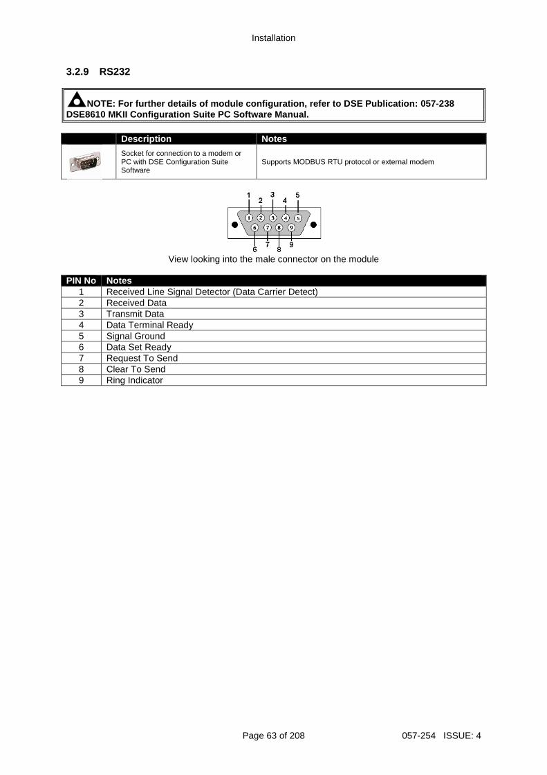
Installation
Page 63 of 208 057-254 ISSUE: 4
3.2.9 RS232
NOTE: For further details of module configuration, refer to DSE Publication: 057-238 DSE8610 MKII Configuration Suite PC Software Manual . Description Notes
Socket for connection to a modem or PC with DSE Configuration Suite Software
Supports MODBUS RTU protocol or external modem
View looking into the male connector on the module
PIN No Notes
1 Received Line Signal Detector (Data Carrier Detect) 2 Received Data 3 Transmit Data 4 Data Terminal Ready 5 Signal Ground 6 Data Set Ready 7 Request To Send 8 Clear To Send 9 Ring Indicator
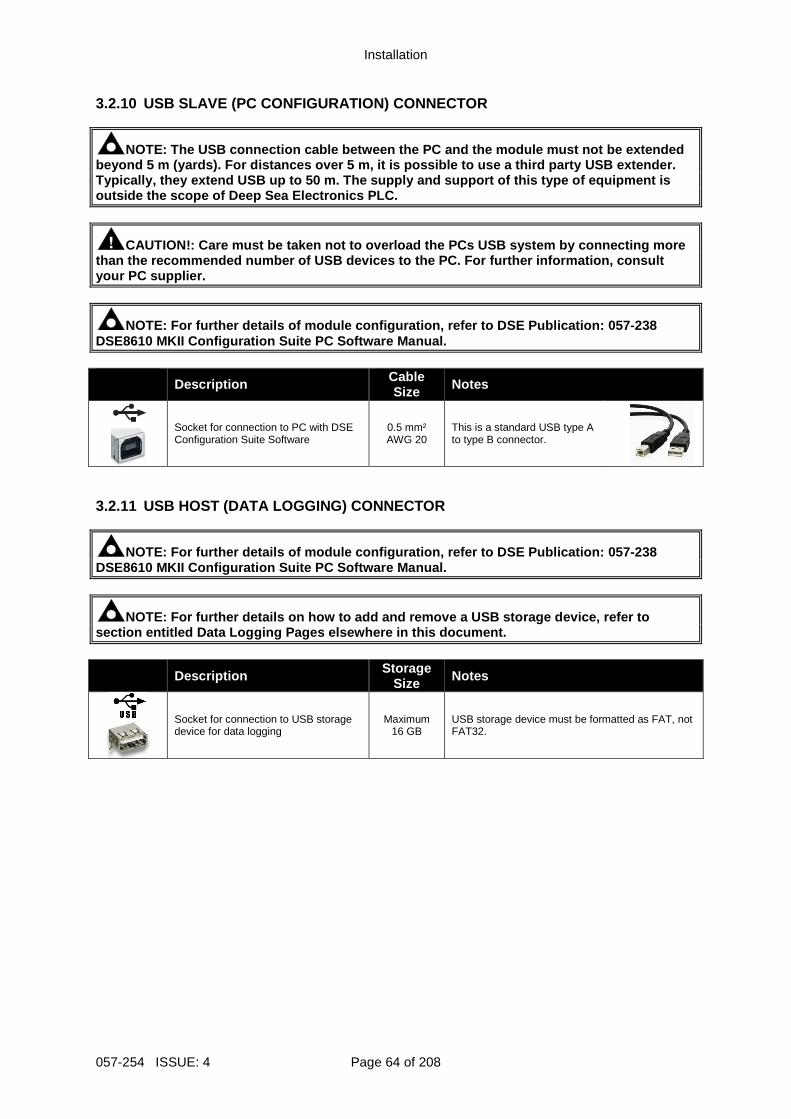
Installation
057-254 ISSUE: 4 Page 64 of 208
3.2.10 USB SLAVE (PC CONFIGURATION) CONNECTOR
NOTE: The USB connection cable between the PC and t he module must not be extended beyond 5 m (yards). For distances over 5 m, it is p ossible to use a third party USB extender. Typically, they extend USB up to 50 m. The supply a nd support of this type of equipment is outside the scope of Deep Sea Electronics PLC.
CAUTION!: Care must be taken not to overload the PC s USB system by connecting more than the recommended number of USB devices to the P C. For further information, consult your PC supplier.
NOTE: For further details of module configuration, refer to DSE Publication: 057-238 DSE8610 MKII Configuration Suite PC Software Manual . Description Cable
Size Notes
Socket for connection to PC with DSE Configuration Suite Software
0.5 mm² AWG 20
This is a standard USB type A to type B connector.
3.2.11 USB HOST (DATA LOGGING) CONNECTOR
NOTE: For further details of module configuration, refer to DSE Publication: 057-238 DSE8610 MKII Configuration Suite PC Software Manual .
NOTE: For further details on how to add and remove a USB storage device, refer to section entitled Data Logging Pages elsewhere in this document.
Description Storage Size Notes
Socket for connection to USB storage device for data logging
Maximum 16 GB
USB storage device must be formatted as FAT, not FAT32.
Installation
Page 65 of 208 057-254 ISSUE: 4
3.3 TYPICAL WIRING DIAGRAM As every system has different requirements, these diagrams show only a typical system and do not intend to show a complete system. Genset manufacturers and panel builders may use these diagrams as a starting point; however always refer to the completed system diagram provided by the system manufacturer for complete wiring detail. Further wiring suggestions are available in the following DSE publications, available at www.deepseaplc.com to website members. DSE Part Description
056-022 Breaker Control (Training guide) 056-005 Using CTs With DSE Products 056-022 Breaker Control 056-091 Equipotential Earth Bonding 056-092 Best Practices for Wiring Resistive Sensors
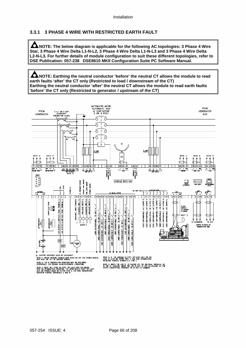
Installation
057-254 ISSUE: 4 Page 66 of 208
3.3.1 3 PHASE 4 WIRE WITH RESTRICTED EARTH FAULT
NOTE: The below diagram is applicable for the follo wing AC topologies: 3 Phase 4 Wire Star, 3 Phase 4 Wire Delta L1-N-L2, 3 Phase 4 Wire Delta L1-N-L3 and 3 Phase 4 Wire Delta L2-N-L3 . For further details of module configuration to su it these different topologies, refer to DSE Publication: 057-238 DSE8610 MKII Configuration Suite PC Softw are Manual.
NOTE: Earthing the neutral conductor ‘before’ the n eutral CT allows the module to read earth faults ‘after’ the CT only (Restricted to loa d / downstream of the CT) Earthing the neutral conductor ‘after’ the neutral CT allows the module to read earth faults ‘before’ the CT only (Restricted to generator / ups tream of the CT)
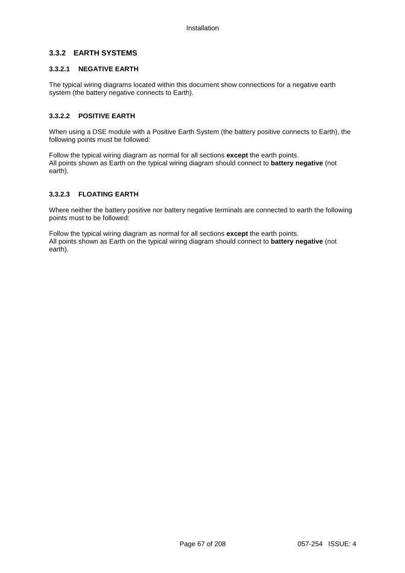
Installation
Page 67 of 208 057-254 ISSUE: 4
3.3.2 EARTH SYSTEMS 3.3.2.1 NEGATIVE EARTH The typical wiring diagrams located within this document show connections for a negative earth system (the battery negative connects to Earth). 3.3.2.2 POSITIVE EARTH When using a DSE module with a Positive Earth System (the battery positive connects to Earth), the following points must be followed: Follow the typical wiring diagram as normal for all sections except the earth points. All points shown as Earth on the typical wiring diagram should connect to battery negative (not earth). 3.3.2.3 FLOATING EARTH Where neither the battery positive nor battery negative terminals are connected to earth the following points must to be followed: Follow the typical wiring diagram as normal for all sections except the earth points. All points shown as Earth on the typical wiring diagram should connect to battery negative (not earth).
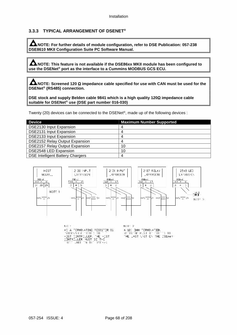
Installation
057-254 ISSUE: 4 Page 68 of 208
3.3.3 TYPICAL ARRANGEMENT OF DSENET ®
NOTE: For further details of module configuration, refer to DSE Publication: 057-238 DSE8610 MKII Configuration Suite PC Software Manual .
NOTE: This feature is not available if the DSE86xx MKII module has been configured to use the DSENet ® port as the interface to a Cummins MODBUS GCS ECU.
NOTE: Screened 120 ΩΩΩΩ impedance cable specified for use with CAN must be used for the DSENet® (RS485) connection. DSE stock and supply Belden cable 9841 which is a h igh quality 120 ΩΩΩΩ impedance cable suitable for DSENet ® use (DSE part number 016-030) Twenty (20) devices can be connected to the DSENet®, made up of the following devices : Device Maximum Number Supported DSE2130 Input Expansion 4 DSE2131 Input Expansion 4 DSE2133 Input Expansion 4 DSE2152 Relay Output Expansion 4 DSE2157 Relay Output Expansion 10 DSE2548 LED Expansion 10 DSE Intelligent Battery Chargers 4
Installation
Page 69 of 208 057-254 ISSUE: 4
3.3.4 TYPICAL ARRANGEMENT OF MSC LINK
NOTE: For further information on the maximum number of module that can be connected to the MSC link and Redundant MSC link, refer to se ctions entitled MSC (Multi-Set Communications) Link and CAN Port (Redundant MSC) elsewhere in this document.
NOTE: For further details of module configuration, refer to DSE Publication: 057-238 DSE8610 MKII Configuration Suite PC Software Manual .
NOTE: Screened 120 ΩΩΩΩ impedance cable specified for use with CAN must be used for the DSENet® (RS485) connection. DSE stock and supply Belden cable 9841 which is a h igh quality 120 ΩΩΩΩ impedance cable suitable for DSENet ® use (DSE part number 016-030)
NOTE: A termination resistor MUST be fitted to the first and last unit on the MSC link.
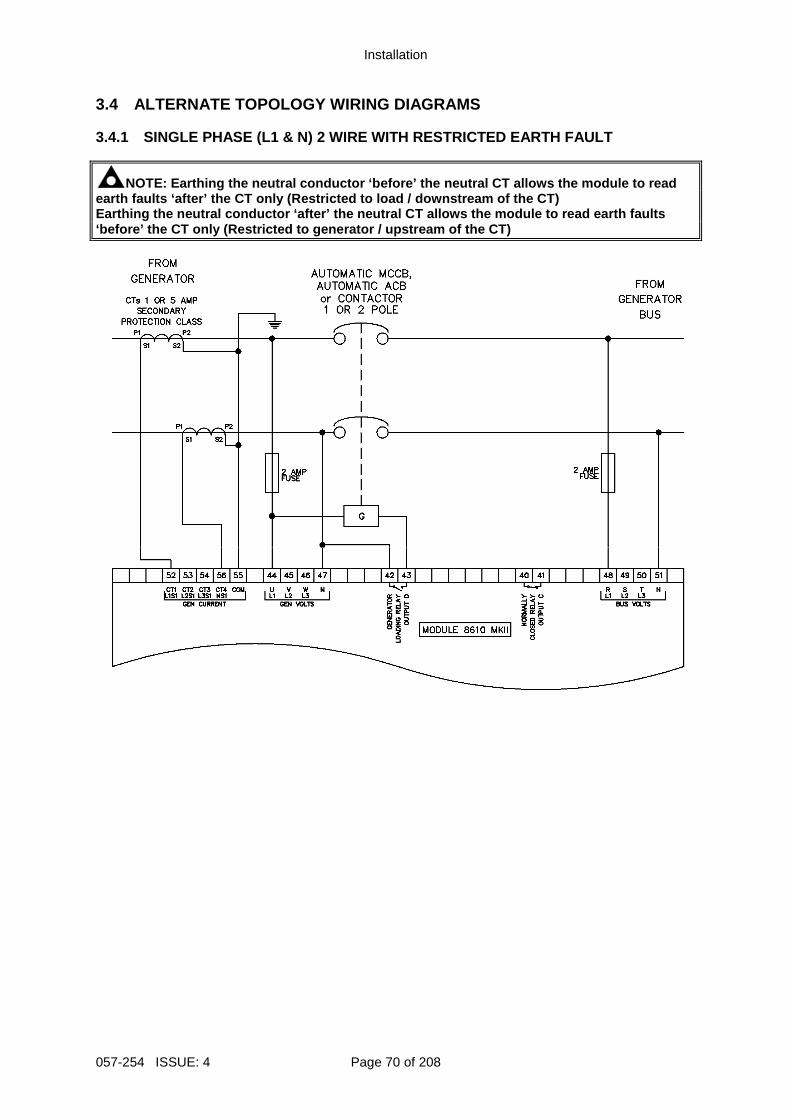
Installation
057-254 ISSUE: 4 Page 70 of 208
3.4 ALTERNATE TOPOLOGY WIRING DIAGRAMS 3.4.1 SINGLE PHASE (L1 & N) 2 WIRE WITH RESTRICTED EARTH FAULT
NOTE: Earthing the neutral conductor ‘before’ the n eutral CT allows the module to read earth faults ‘after’ the CT only (Restricted to loa d / downstream of the CT) Earthing the neutral conductor ‘after’ the neutral CT allows the module to read earth faults ‘before’ the CT only (Restricted to generator / ups tream of the CT)
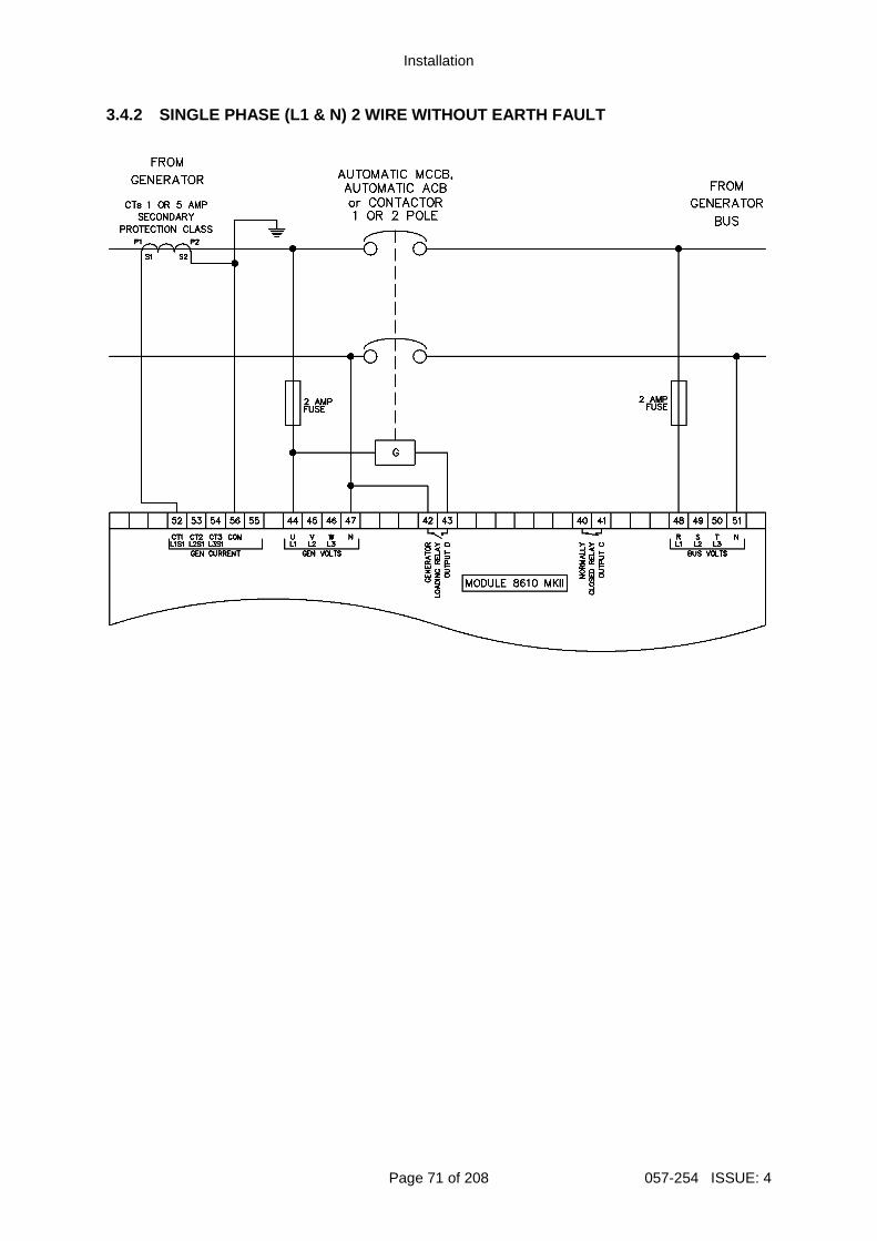
Installation
Page 71 of 208 057-254 ISSUE: 4
3.4.2 SINGLE PHASE (L1 & N) 2 WIRE WITHOUT EARTH FA ULT

Installation
057-254 ISSUE: 4 Page 72 of 208
3.4.3 SINGLE PHASE (L1 & L2) 3 WIRE WITH RESTRICTED EARTH FAULT
NOTE: Earthing the neutral conductor ‘before’ the n eutral CT allows the module to read earth faults ‘after’ the CT only (Restricted to loa d / downstream of the CT) Earthing the neutral conductor ‘after’ the neutral CT allows the module to read earth faults ‘before’ the CT only (Restricted to generator / ups tream of the CT)
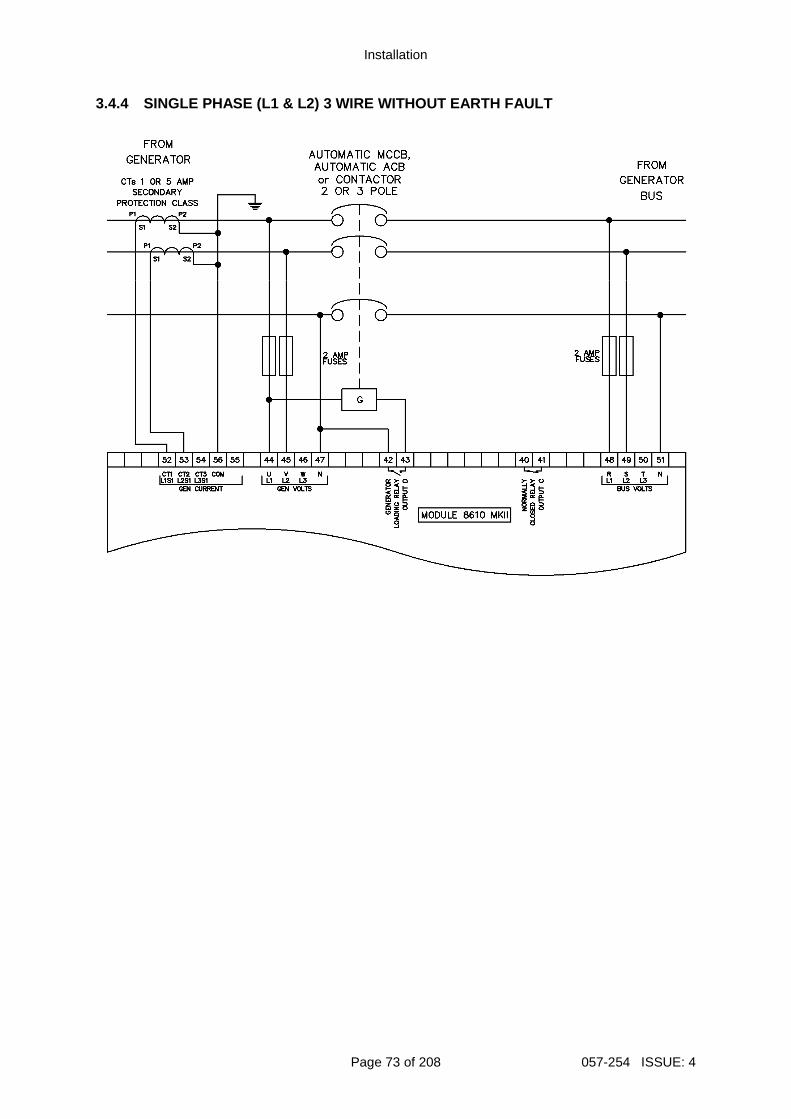
Installation
Page 73 of 208 057-254 ISSUE: 4
3.4.4 SINGLE PHASE (L1 & L2) 3 WIRE WITHOUT EARTH F AULT
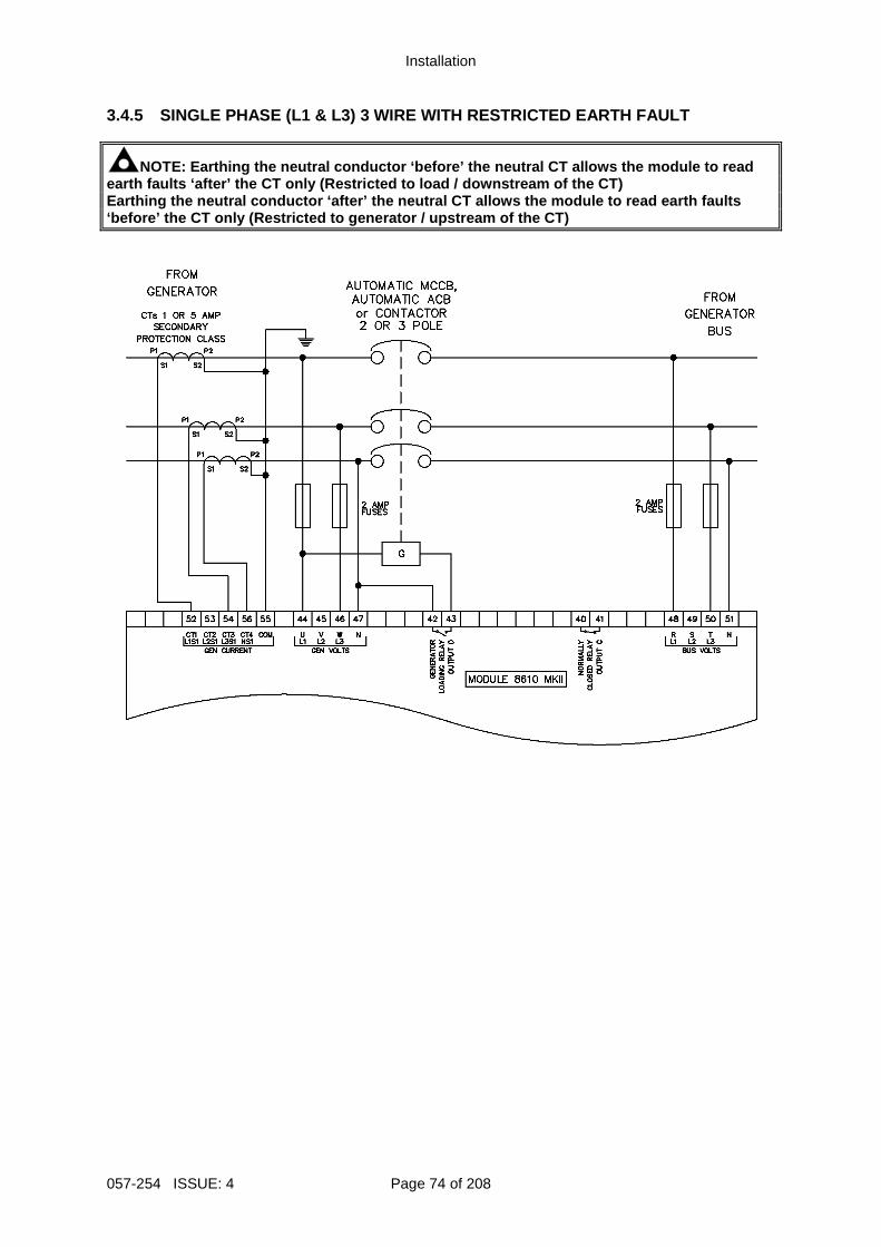
Installation
057-254 ISSUE: 4 Page 74 of 208
3.4.5 SINGLE PHASE (L1 & L3) 3 WIRE WITH RESTRICTED EARTH FAULT
NOTE: Earthing the neutral conductor ‘before’ the n eutral CT allows the module to read earth faults ‘after’ the CT only (Restricted to loa d / downstream of the CT) Earthing the neutral conductor ‘after’ the neutral CT allows the module to read earth faults ‘before’ the CT only (Restricted to generator / ups tream of the CT)
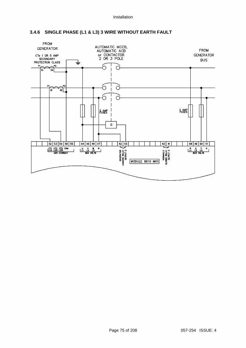
Installation
Page 75 of 208 057-254 ISSUE: 4
3.4.6 SINGLE PHASE (L1 & L3) 3 WIRE WITHOUT EARTH F AULT
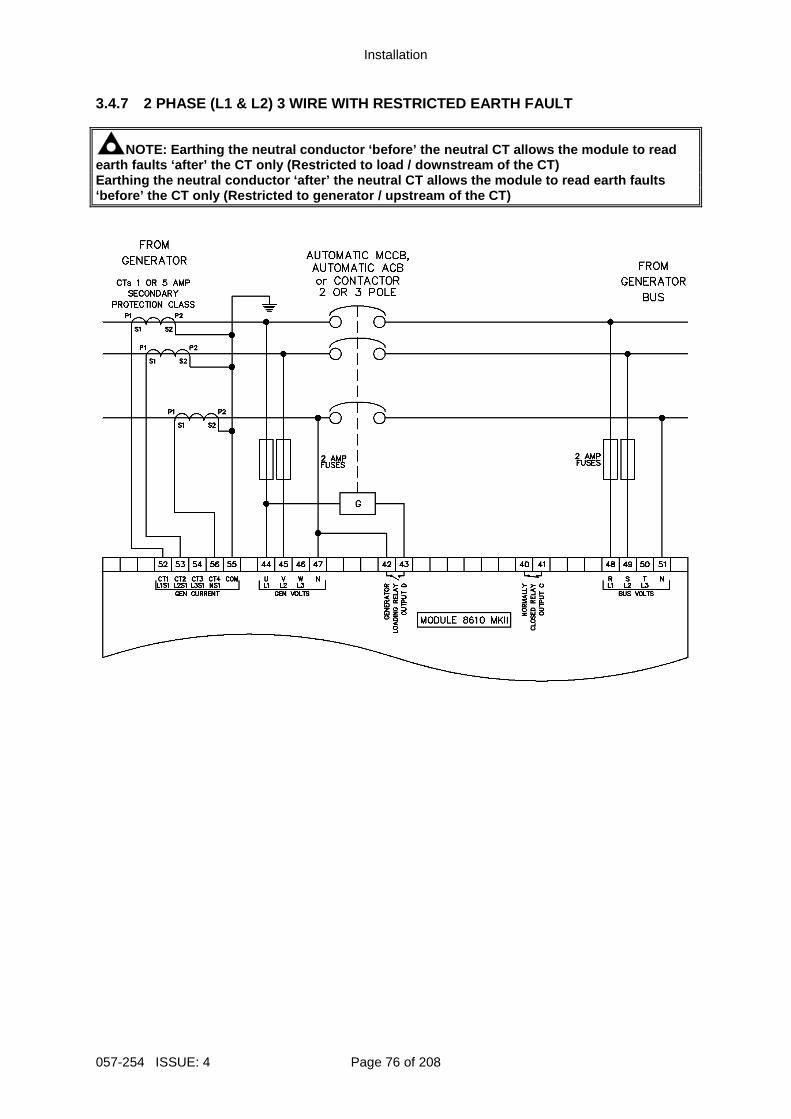
Installation
057-254 ISSUE: 4 Page 76 of 208
3.4.7 2 PHASE (L1 & L2) 3 WIRE WITH RESTRICTED EART H FAULT
NOTE: Earthing the neutral conductor ‘before’ the n eutral CT allows the module to read earth faults ‘after’ the CT only (Restricted to loa d / downstream of the CT) Earthing the neutral conductor ‘after’ the neutral CT allows the module to read earth faults ‘before’ the CT only (Restricted to generator / ups tream of the CT)
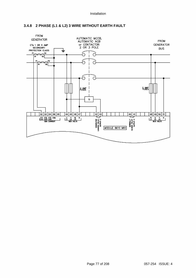
Installation
Page 77 of 208 057-254 ISSUE: 4
3.4.8 2 PHASE (L1 & L2) 3 WIRE WITHOUT EARTH FAULT

Installation
057-254 ISSUE: 4 Page 78 of 208
3.4.9 2 PHASE (L1 & L3) 3 WIRE WITH RESTRICTED EART H FAULT
NOTE: Earthing the neutral conductor ‘before’ the n eutral CT allows the module to read earth faults ‘after’ the CT only (Restricted to loa d / downstream of the CT) Earthing the neutral conductor ‘after’ the neutral CT allows the module to read earth faults ‘before’ the CT only (Restricted to generator / ups tream of the CT)

Installation
Page 79 of 208 057-254 ISSUE: 4
3.4.10 2 PHASE (L1 & L3) 3 WIRE WITHOUT EARTH FAULT
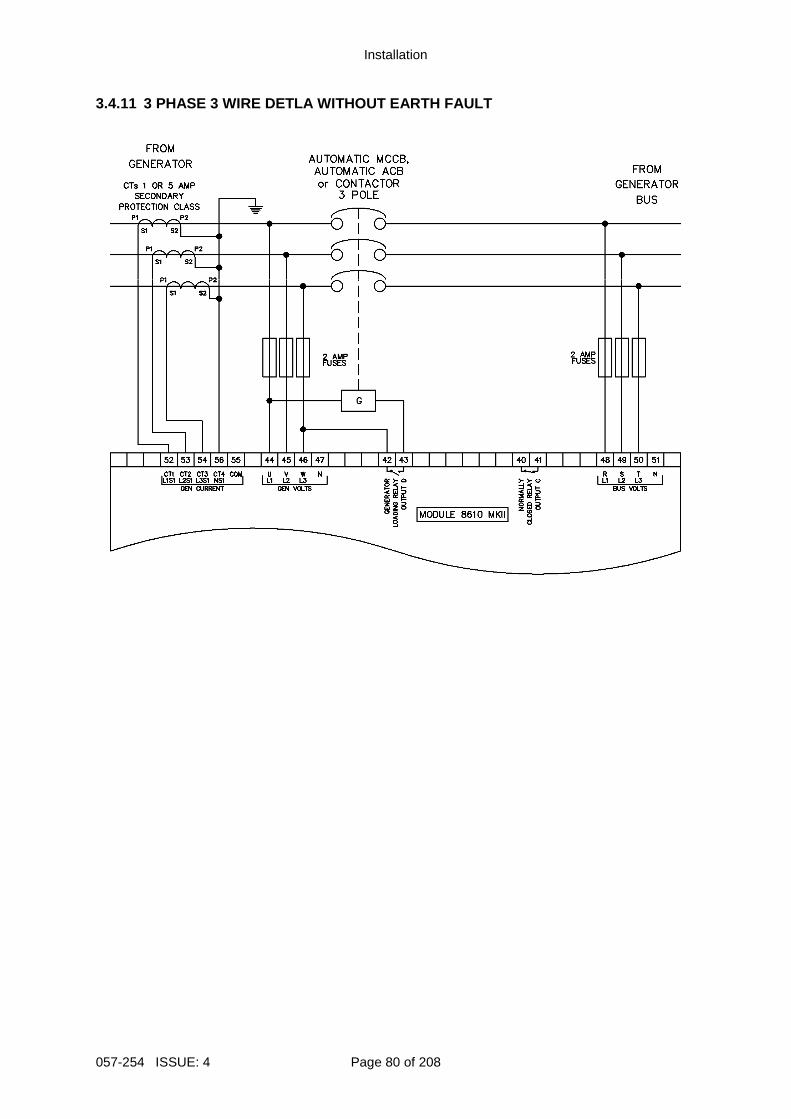
Installation
057-254 ISSUE: 4 Page 80 of 208
3.4.11 3 PHASE 3 WIRE DETLA WITHOUT EARTH FAULT
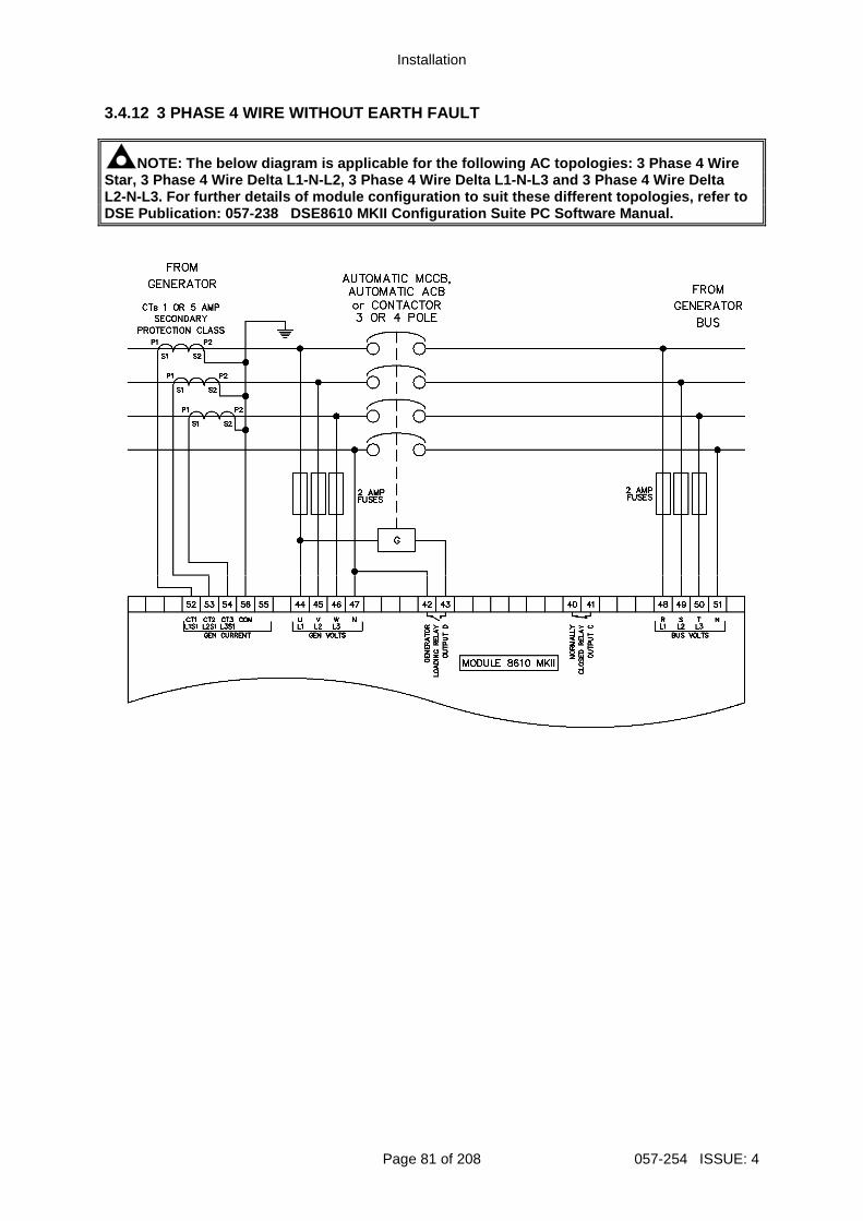
Installation
Page 81 of 208 057-254 ISSUE: 4
3.4.12 3 PHASE 4 WIRE WITHOUT EARTH FAULT
NOTE: The below diagram is applicable for the follo wing AC topologies: 3 Phase 4 Wire Star, 3 Phase 4 Wire Delta L1-N-L2, 3 Phase 4 Wire Delta L1-N-L3 and 3 Phase 4 Wire Delta L2-N-L3 . For further details of module configuration to su it these different topologies, refer to DSE Publication: 057-238 DSE8610 MKII Configuration Suite PC Softw are Manual.
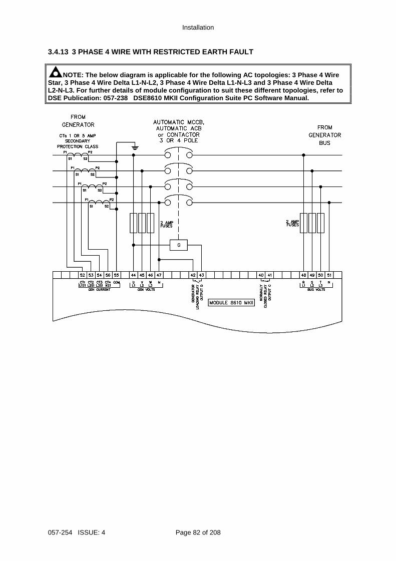
Installation
057-254 ISSUE: 4 Page 82 of 208
3.4.13 3 PHASE 4 WIRE WITH RESTRICTED EARTH FAULT
NOTE: The below diagram is applicable for the follo wing AC topologies: 3 Phase 4 Wire Star, 3 Phase 4 Wire Delta L1-N-L2, 3 Phase 4 Wire Delta L1-N-L3 and 3 Phase 4 Wire Delta L2-N-L3 . For further details of module configuration to su it these different topologies, refer to DSE Publication: 057-238 DSE8610 MKII Configuration Suite PC Softw are Manual.
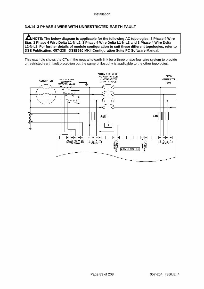
Installation
Page 83 of 208 057-254 ISSUE: 4
3.4.14 3 PHASE 4 WIRE WITH UNRESTRICTED EARTH FAULT
NOTE: The below diagram is applicable for the follo wing AC topologies: 3 Phase 4 Wire Star, 3 Phase 4 Wire Delta L1-N-L2, 3 Phase 4 Wire Delta L1-N-L3 and 3 Phase 4 Wire Delta L2-N-L3 . For further details of module configuration to su it these different topologies, refer to DSE Publication: 057-238 DSE8610 MKII Configuration Suite PC Softw are Manual. This example shows the CTs in the neutral to earth link for a three phase four wire system to provide unrestricted earth fault protection but the same philosophy is applicable to the other topologies.
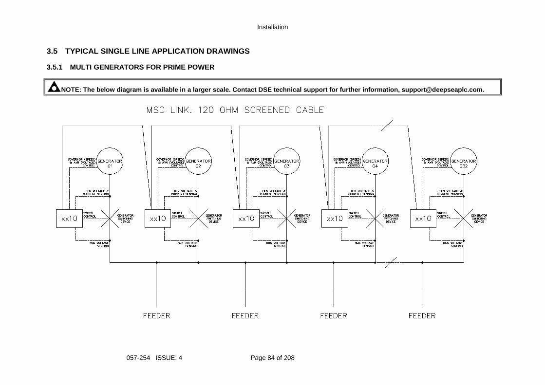
Installation
057-254 ISSUE: 4 Page 84 of 208
3.5 TYPICAL SINGLE LINE APPLICATION DRAWINGS 3.5.1 MULTI GENERATORS FOR PRIME POWER
NOTE: The below diagram is available in a larger sc ale. Contact DSE technical support for further info rmation, [email protected].
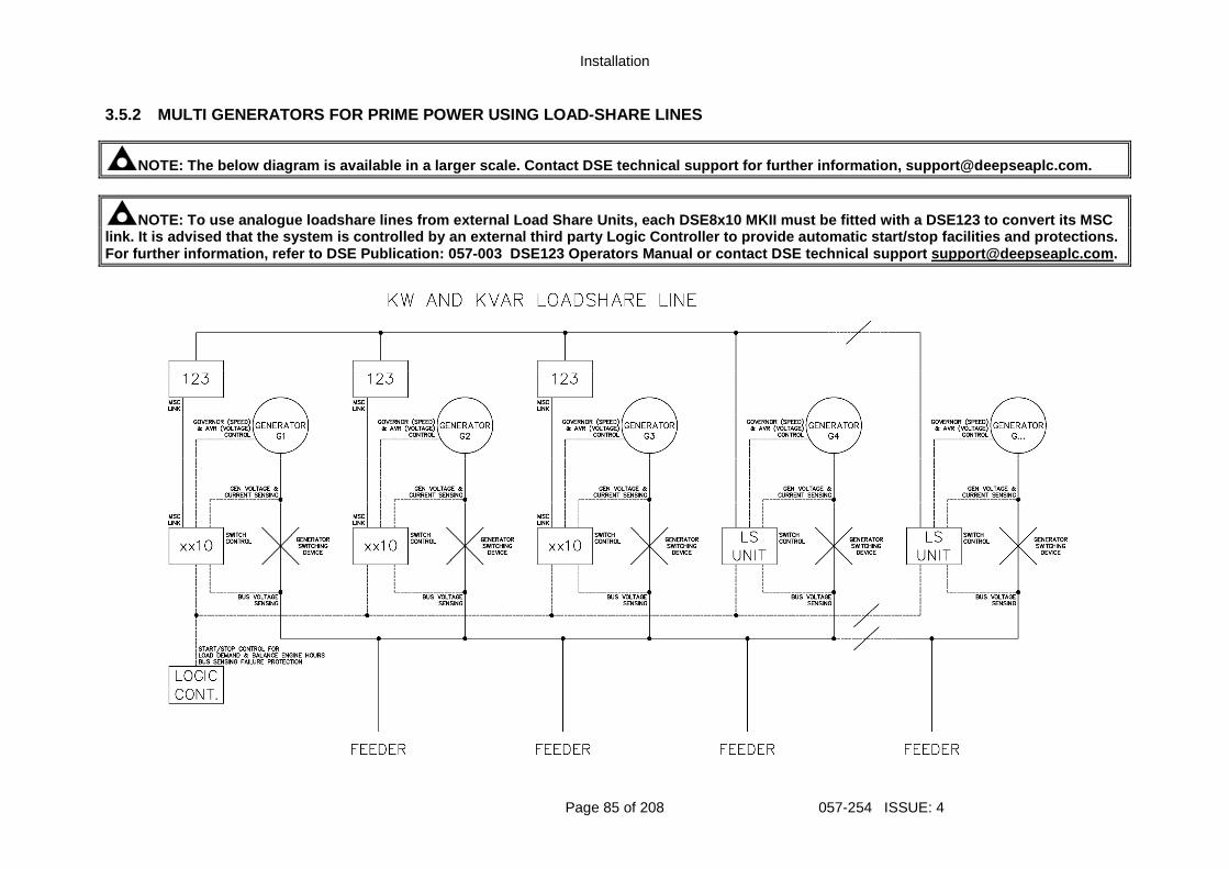
Installation
Page 85 of 208 057-254 ISSUE: 4
3.5.2 MULTI GENERATORS FOR PRIME POWER USING LOAD-S HARE LINES
NOTE: The below diagram is available in a larger sc ale. Contact DSE technical support for further info rmation, [email protected].
NOTE: To use analogue loadshare lines from external Load Share Units , each DSE8x10 MKII must be fitted with a DSE123 to convert its MSC link. It is advised that the system is controlled b y an external third party Logic Controller to provide automatic start/stop facilities and pro tections. For further information, refer to DSE Publication: 057-003 DSE123 Operators Manual or contact DSE technical support support@deepseaplc .com.
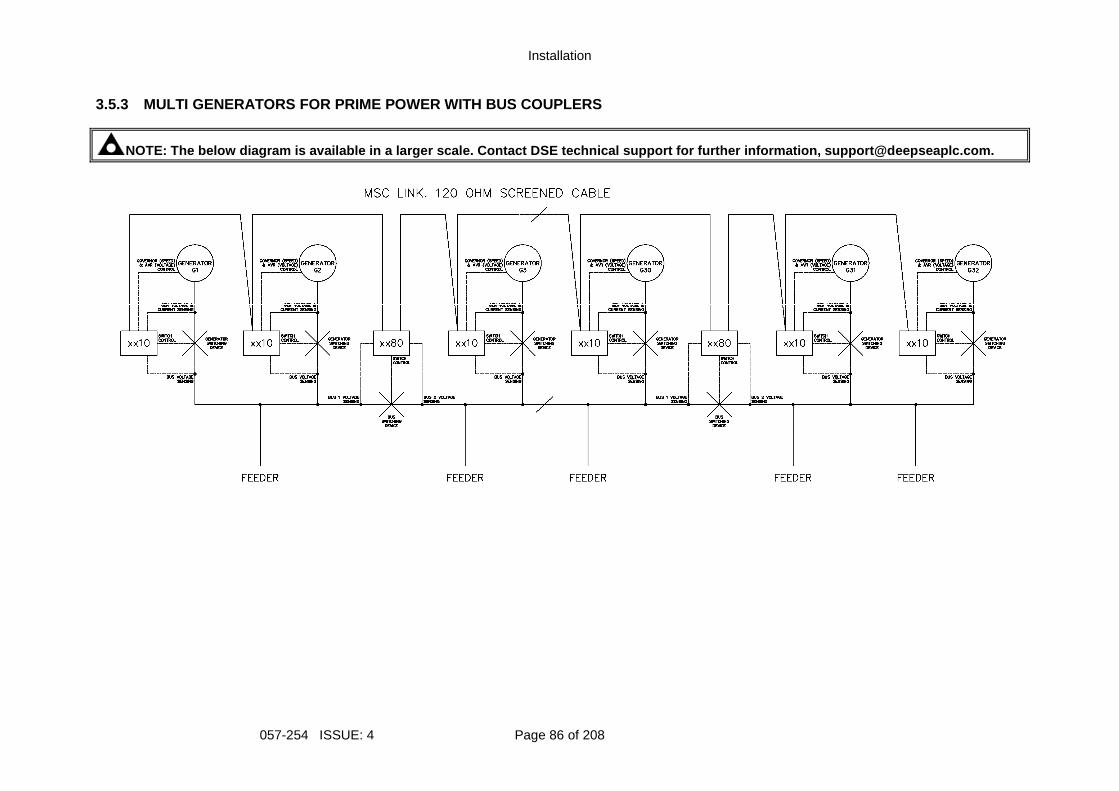
Installation
057-254 ISSUE: 4 Page 86 of 208
3.5.3 MULTI GENERATORS FOR PRIME POWER WITH BUS COU PLERS
NOTE: The below diagram is available in a larger sc ale. Contact DSE technical support for further info rmation, [email protected].
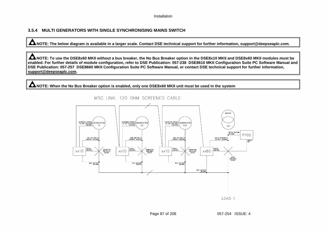
Installation
Page 87 of 208 057-254 ISSUE: 4
3.5.4 MULTI GENERATORS WITH SINGLE SYNCHRONISING MA INS SWITCH
NOTE: The below diagram is available in a larger sc ale. Contact DSE technical support for further info rmation, [email protected].
NOTE: To use the DSE8x60 MKII without a bus breaker , the No Bus Breaker option in the DSE8x10 MKII and DSE8x60 MKII modules must be enabled. For further details of module configuratio n, refer to DSE Publication: 057-238 DSE8610 MKII Configuration Suite PC Software Manual and DSE Publication: 057-257 DSE8660 MKII Configuration Suite PC Software Manual , or contact DSE technical support for further info rmation, [email protected].
NOTE: When the No Bus Breaker option is enabled, only one DSE8x60 MKII unit must be used in the system
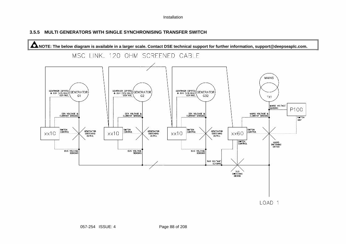
Installation
057-254 ISSUE: 4 Page 88 of 208
3.5.5 MULTI GENERATORS WITH SINGLE SYNCHRONISING TR ANSFER SWITCH
NOTE: The below diagram is available in a larger sc ale. Contact DSE technical support for further info rmation, [email protected].
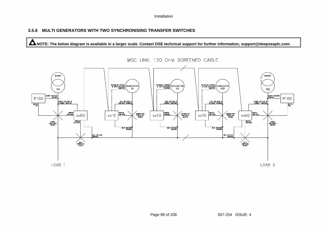
Installation
Page 89 of 208 057-254 ISSUE: 4
3.5.6 MULTI GENERATORS WITH TWO SYNCHRONISING TRANS FER SWITCHES
NOTE: The below diagram is available in a larger sc ale. Contact DSE technical support for further info rmation, [email protected].
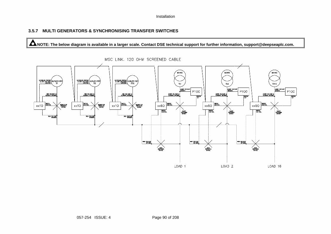
Installation
057-254 ISSUE: 4 Page 90 of 208
3.5.7 MULTI GENERATORS & SYNCHRONISING TRANSFER SWI TCHES
NOTE: The below diagram is available in a larger sc ale. Contact DSE technical support for further info rmation, [email protected].
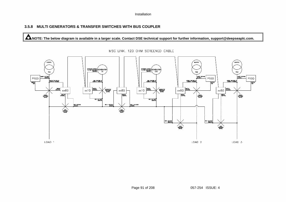
Installation
Page 91 of 208 057-254 ISSUE: 4
3.5.8 MULTI GENERATORS & TRANSFER SWITCHES WITH BUS COUPLER
NOTE: The below diagram is available in a larger sc ale. Contact DSE technical support for further info rmation, [email protected].
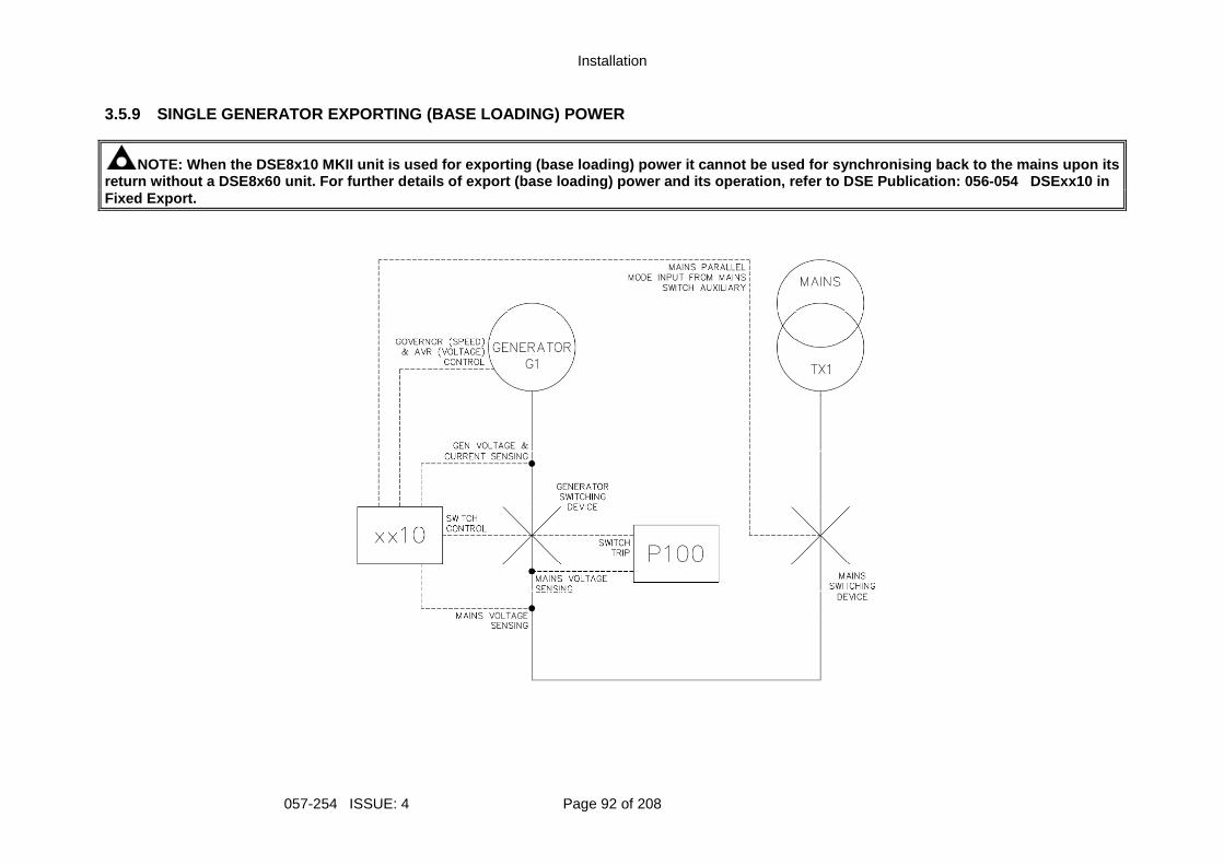
Installation
057-254 ISSUE: 4 Page 92 of 208
3.5.9 SINGLE GENERATOR EXPORTING (BASE LOADING) POW ER
NOTE: When the DSE8x10 MKII unit is used for export ing (base loading) power it cannot be used for sync hronising back to the mains upon its return without a DSE8x60 unit. For further details of export (base loading) power and its operation, r efer to DSE Publication: 056-054 DSExx10 in Fixed Export.
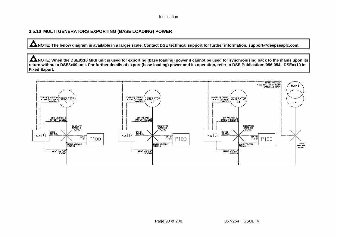
Installation
Page 93 of 208 057-254 ISSUE: 4
3.5.10 MULTI GENERATORS EXPORTING (BASE LOADING) PO WER
NOTE: The below diagram is available in a larger sc ale. Contact DSE technical support for further info rmation, [email protected].
NOTE: When the DSE8x10 MKII unit is used for export ing (base loading) power it cannot be used for sync hronising back to the mains upon its return without a DSE8x60 unit. For further details of export (base loading) power and its operation, r efer to DSE Publication: 056-054 DSExx10 in Fixed Export.
Description of Controls
057-254 ISSUE: 4 Page 94 of 208
4 DESCRIPTION OF CONTROLS
CAUTION: The module may instruct an engine start ev ent due to external influences. Therefore, it is possible for the engine to start a t any time without warning. Prior to performing any maintenance on the system, it is recommended th at steps are taken to remove the battery and isolate supplies.
NOTE: The following descriptions detail the sequenc es followed by a module containing the standard ‘factory configuration’. Always refer to your configuration source for the exact sequences and timers observed by any particular mod ule in the field. Control of the module is via push buttons mounted on the front of the module with
Stop/Reset Mode , Manual Mode , Auto Mode ,Start Close Generator and
Open Generator functions. For normal operation, these are the only controls which need to be operated. Details of their operation are provided later in this document.
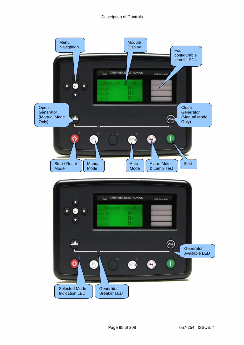
Description of Controls
Page 95 of 208 057-254 ISSUE: 4
Menu Navigation
Module Display
Stop / Reset Mode
Manual Mode
Auto Mode
Alarm Mute & Lamp Test
Start
Four configurable status LEDs
Close Generator (Manual Mode Only)
Open Generator (Manual Mode Only)
Generator Breaker LED
Selected Mode Indication LED
Generator Available LED
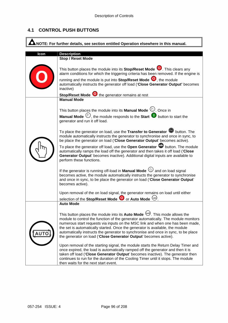
Description of Controls
057-254 ISSUE: 4 Page 96 of 208
4.1 CONTROL PUSH BUTTONS
NOTE: For further details, see section entitled Operation elsewhere in this manual.
Icon Description
Stop / Reset Mode
This button places the module into its Stop/Reset Mode . This clears any alarm conditions for which the triggering criteria has been removed. If the engine is
running and the module is put into Stop/Reset Mode , the module automatically instructs the generator off load (‘Close Generator Output’ becomes inactive)
Stop/Reset Mode the generator remains at rest
Manual Mode
This button places the module into its Manual Mode . Once in
Manual Mode , the module responds to the Start button to start the generator and run it off load.
To place the generator on load, use the Transfer to Generator button. The module automatically instructs the generator to synchronise and once in sync, to be place the generator on load (‘Close Generator Output ’ becomes active).
To place the generator off load, use the Open Generator button. The module automatically ramps the load off the generator and then takes it off load (‘Close Generator Output ’ becomes inactive). Additional digital inputs are available to perform these functions.
If the generator is running off-load in Manual Mode and on load signal becomes active, the module automatically instructs the generator to synchronise and once in sync, to be place the generator on load (‘Close Generator Output ’ becomes active). Upon removal of the on load signal, the generator remains on load until either
selection of the Stop/Reset Mode or Auto Mode .
Auto Mode
This button places the module into its Auto Mode . This mode allows the module to control the function of the generator automatically. The module monitors numerous start requests via inputs on the MSC link and when one has been made, the set is automatically started. Once the generator is available, the module automatically instructs the generator to synchronise and once in sync, to be place the generator on load (‘Close Generator Output ’ becomes active). Upon removal of the starting signal, the module starts the Return Delay Timer and once expired, the load is automatically ramped off the generator and then it is taken off load (‘Close Generator Output ’ becomes inactive). The generator then continues to run for the duration of the Cooling Timer until it stops. The module then waits for the next start event.
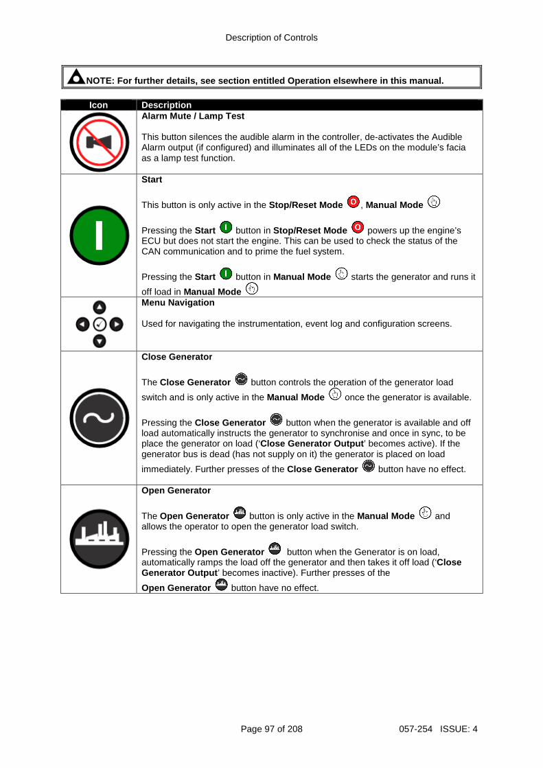
Description of Controls
Page 97 of 208 057-254 ISSUE: 4
NOTE: For further details, see section entitled Operation elsewhere in this manual.
Icon Description
Alarm Mute / Lamp Test This button silences the audible alarm in the controller, de-activates the Audible Alarm output (if configured) and illuminates all of the LEDs on the module’s facia as a lamp test function.
Start
This button is only active in the Stop/Reset Mode , Manual Mode
Pressing the Start button in Stop/Reset Mode powers up the engine’s ECU but does not start the engine. This can be used to check the status of the CAN communication and to prime the fuel system.
Pressing the Start button in Manual Mode starts the generator and runs it
off load in Manual Mode
Menu Navigation Used for navigating the instrumentation, event log and configuration screens.
Close Generator
The Close Generator button controls the operation of the generator load
switch and is only active in the Manual Mode once the generator is available.
Pressing the Close Generator button when the generator is available and off load automatically instructs the generator to synchronise and once in sync, to be place the generator on load (‘Close Generator Output ’ becomes active). If the generator bus is dead (has not supply on it) the generator is placed on load
immediately. Further presses of the Close Generator button have no effect.
Open Generator
The Open Generator button is only active in the Manual Mode and allows the operator to open the generator load switch.
Pressing the Open Generator button when the Generator is on load, automatically ramps the load off the generator and then takes it off load (‘Close Generator Output ’ becomes inactive). Further presses of the
Open Generator button have no effect.
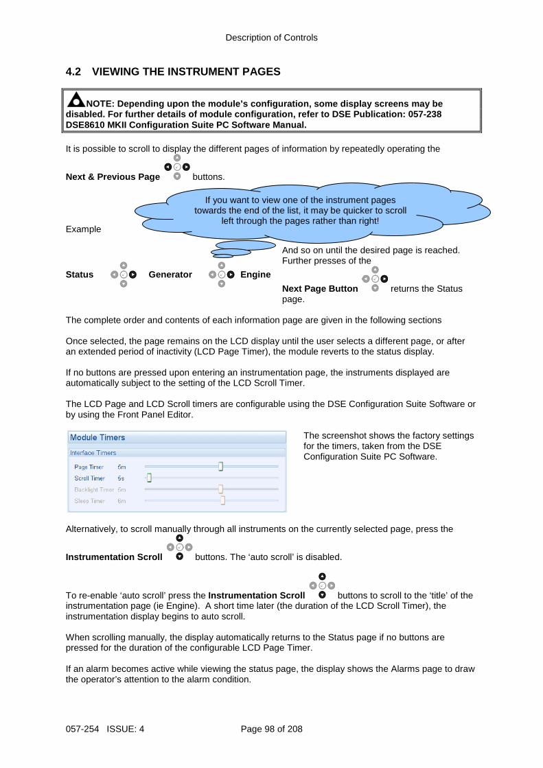
Description of Controls
057-254 ISSUE: 4 Page 98 of 208
4.2 VIEWING THE INSTRUMENT PAGES
NOTE: Depending upon the module’s configuration, so me display screens may be disabled. For further details of module configurati on, refer to DSE Publication: 057-238 DSE8610 MKII Configuration Suite PC Software Manual . It is possible to scroll to display the different pages of information by repeatedly operating the
Next & Previous Page buttons. Example
Status
Generator
Engine
And so on until the desired page is reached. Further presses of the
Next Page Button returns the Status page.
The complete order and contents of each information page are given in the following sections Once selected, the page remains on the LCD display until the user selects a different page, or after an extended period of inactivity (LCD Page Timer), the module reverts to the status display. If no buttons are pressed upon entering an instrumentation page, the instruments displayed are automatically subject to the setting of the LCD Scroll Timer. The LCD Page and LCD Scroll timers are configurable using the DSE Configuration Suite Software or by using the Front Panel Editor.
The screenshot shows the factory settings for the timers, taken from the DSE Configuration Suite PC Software.
Alternatively, to scroll manually through all instruments on the currently selected page, press the
Instrumentation Scroll buttons. The ‘auto scroll’ is disabled.
To re-enable ‘auto scroll’ press the Instrumentation Scroll buttons to scroll to the ‘title’ of the instrumentation page (ie Engine). A short time later (the duration of the LCD Scroll Timer), the instrumentation display begins to auto scroll. When scrolling manually, the display automatically returns to the Status page if no buttons are pressed for the duration of the configurable LCD Page Timer. If an alarm becomes active while viewing the status page, the display shows the Alarms page to draw the operator’s attention to the alarm condition.
If you want to view one of the instrument pages towards the end of the list, it may be quicker to scroll
left through the pages rather than right!
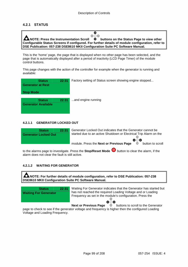
Description of Controls
Page 99 of 208 057-254 ISSUE: 4
4.2.1 STATUS
NOTE: Press the Instrumentation Scroll buttons on the Status Page to view other Configurable Status Screens if configured. For furt her details of module configuration, refer to DSE Publication: 057-238 DSE8610 MKII Configuration Suite PC Softwar e Manual. This is the ‘home’ page, the page that is displayed when no other page has been selected, and the page that is automatically displayed after a period of inactivity (LCD Page Timer) of the module control buttons. This page changes with the action of the controller for example when the generator is running and available:
Status 22:31 Factory setting of Status screen showing engine stopped... Generator at Rest
Stop Mode
Status 22:31 ...and engine running Generator Available
4.2.1.1 GENERATOR LOCKED OUT Status 22:31 Generator Locked Out indicates that the Generator cannot be
started due to an active Shutdown or Electrical Trip Alarm on the
module. Press the Next or Previous Page button to scroll
Generator Locked Out
to the alarms page to investigate. Press the Stop/Reset Mode button to clear the alarm, if the alarm does not clear the fault is still active. 4.2.1.2 WAITING FOR GENERATOR
NOTE: For further details of module configuration, refer to DSE Publication: 057-238 DSE8610 MKII Configuration Suite PC Software Manual . Status 22:31 Waiting For Generator indicates that the Generator has started but
has not reached the required Loading Voltage and or Loading Frequency as set in the module’s configuration. Press the
Next or Previous Page buttons to scroll to the Generator
Waiting For Generator
page to check to see if the generator voltage and frequency is higher then the configured Loading Voltage and Loading Frequency.
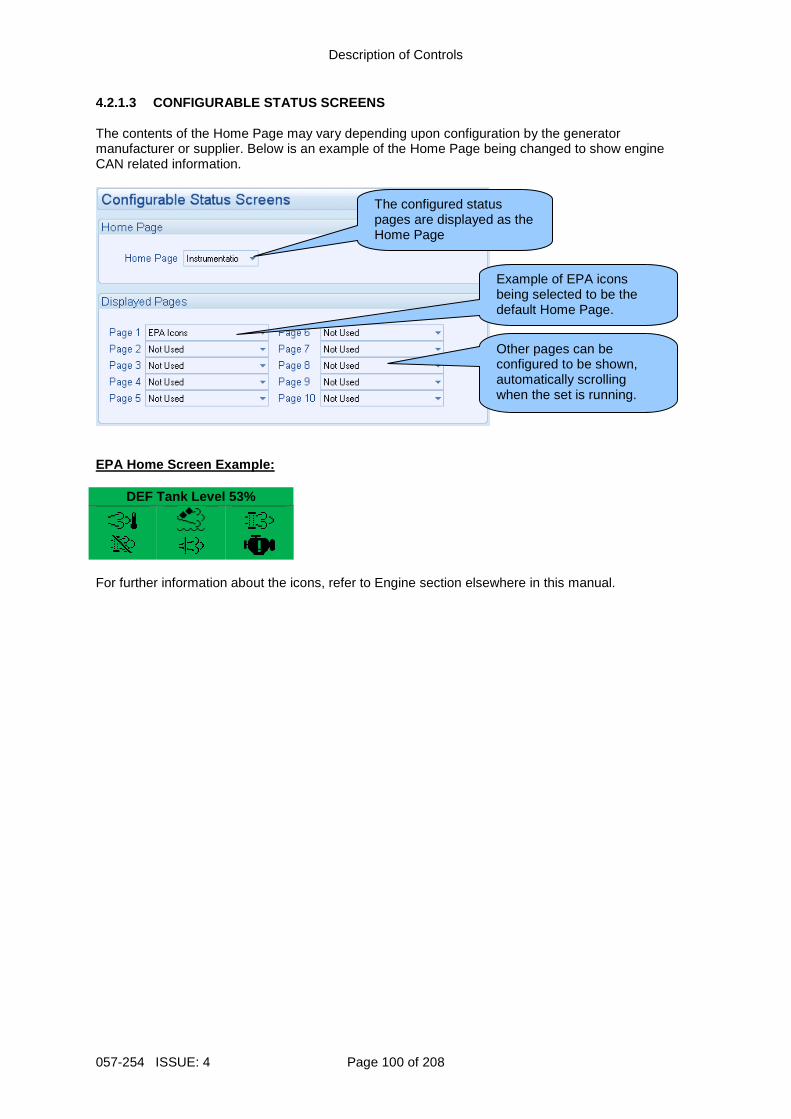
Description of Controls
057-254 ISSUE: 4 Page 100 of 208
4.2.1.3 CONFIGURABLE STATUS SCREENS The contents of the Home Page may vary depending upon configuration by the generator manufacturer or supplier. Below is an example of the Home Page being changed to show engine CAN related information.
EPA Home Screen Example:
DEF Tank Level 53%
For further information about the icons, refer to Engine section elsewhere in this manual.
The configured status pages are displayed as the Home Page
Example of EPA icons being selected to be the default Home Page.
Other pages can be configured to be shown, automatically scrolling when the set is running.
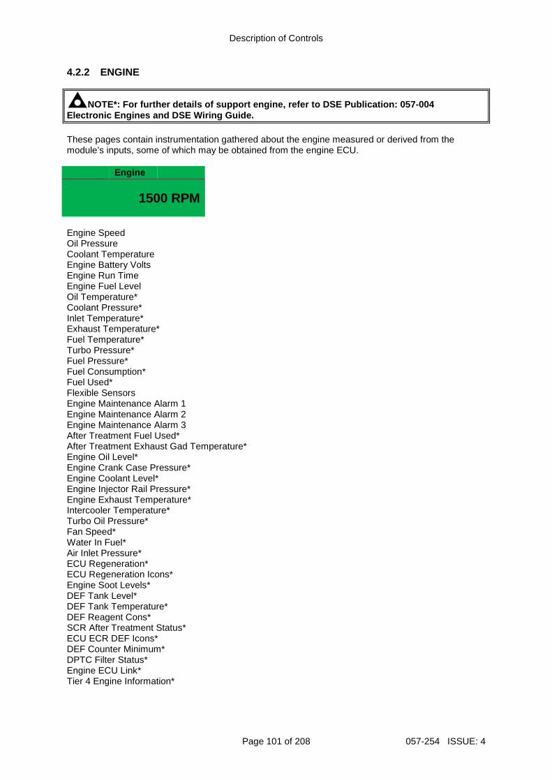
Description of Controls
Page 101 of 208 057-254 ISSUE: 4
4.2.2 ENGINE
NOTE*: For further details of support engine, refer to DSE Publication: 057-004 Electronic Engines and DSE Wiring Guide. These pages contain instrumentation gathered about the engine measured or derived from the module’s inputs, some of which may be obtained from the engine ECU.
Engine
1500 RPM
Engine Speed Oil Pressure Coolant Temperature Engine Battery Volts Engine Run Time Engine Fuel Level Oil Temperature* Coolant Pressure* Inlet Temperature* Exhaust Temperature* Fuel Temperature* Turbo Pressure* Fuel Pressure* Fuel Consumption* Fuel Used* Flexible Sensors Engine Maintenance Alarm 1 Engine Maintenance Alarm 2 Engine Maintenance Alarm 3 After Treatment Fuel Used* After Treatment Exhaust Gad Temperature* Engine Oil Level* Engine Crank Case Pressure* Engine Coolant Level* Engine Injector Rail Pressure* Engine Exhaust Temperature* Intercooler Temperature* Turbo Oil Pressure* Fan Speed* Water In Fuel* Air Inlet Pressure* ECU Regeneration* ECU Regeneration Icons* Engine Soot Levels* DEF Tank Level* DEF Tank Temperature* DEF Reagent Cons* SCR After Treatment Status* ECU ECR DEF Icons* DEF Counter Minimum* DPTC Filter Status* Engine ECU Link* Tier 4 Engine Information*
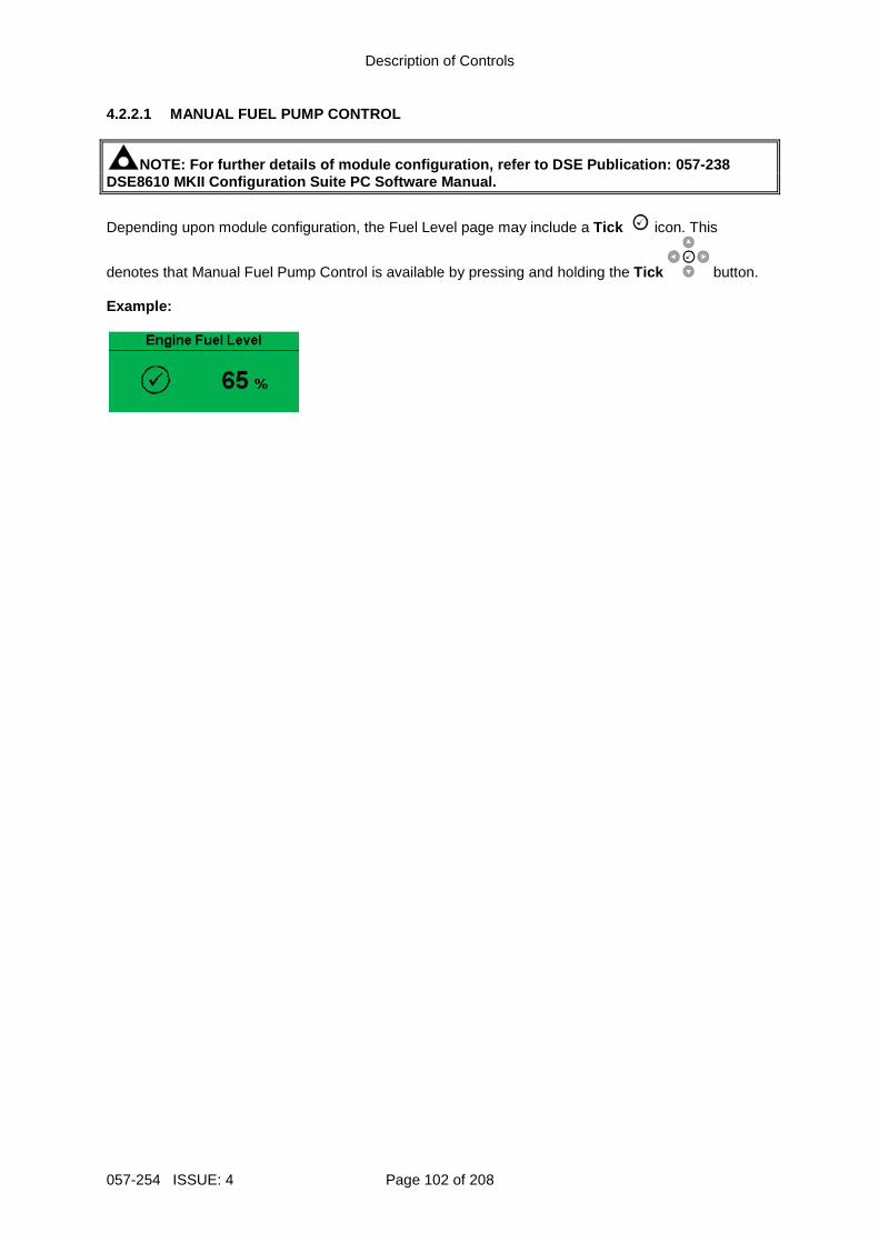
Description of Controls
057-254 ISSUE: 4 Page 102 of 208
4.2.2.1 MANUAL FUEL PUMP CONTROL
NOTE: For further details of module configuration, refer to DSE Publication: 057-238 DSE8610 MKII Configuration Suite PC Software Manual .
Depending upon module configuration, the Fuel Level page may include a Tick icon. This
denotes that Manual Fuel Pump Control is available by pressing and holding the Tick button. Example:
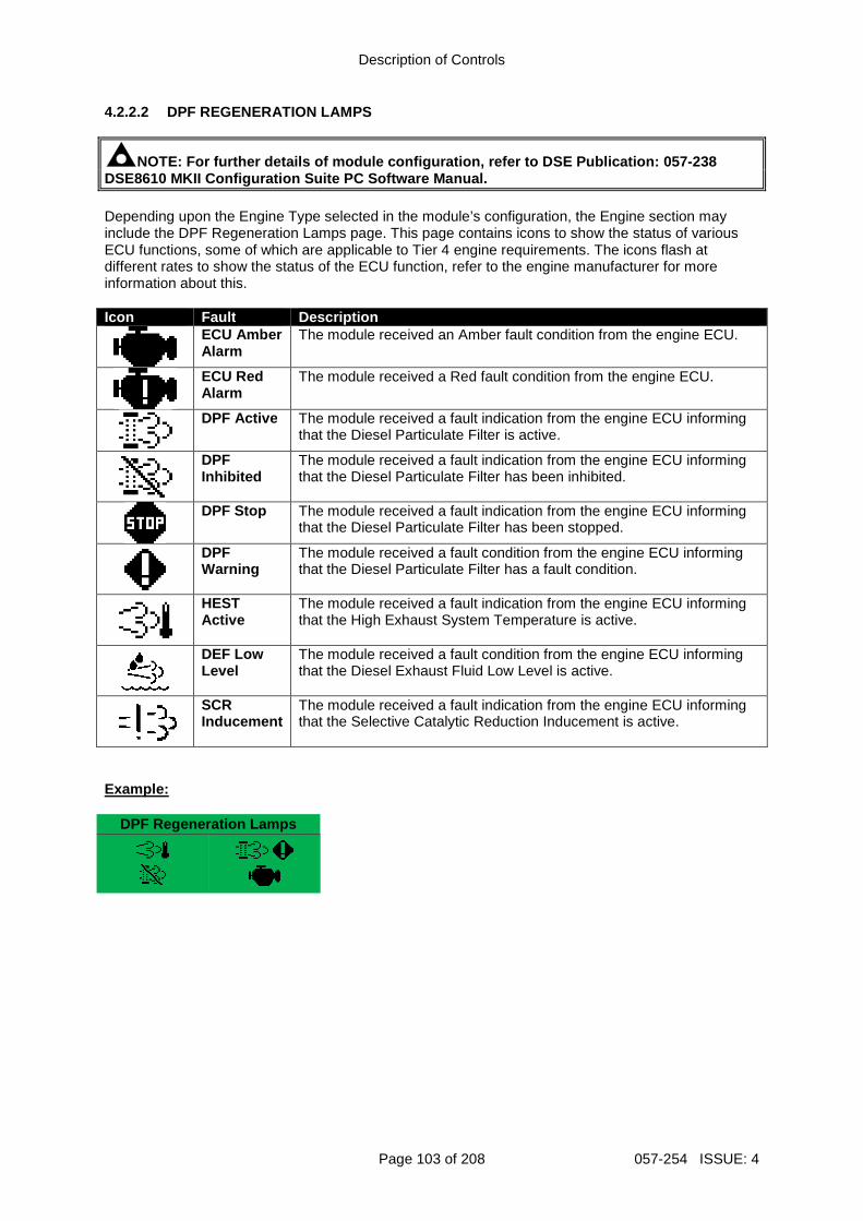
Description of Controls
Page 103 of 208 057-254 ISSUE: 4
4.2.2.2 DPF REGENERATION LAMPS
NOTE: For further details of module configuration, refer to DSE Publication: 057-238 DSE8610 MKII Configuration Suite PC Software Manual . Depending upon the Engine Type selected in the module’s configuration, the Engine section may include the DPF Regeneration Lamps page. This page contains icons to show the status of various ECU functions, some of which are applicable to Tier 4 engine requirements. The icons flash at different rates to show the status of the ECU function, refer to the engine manufacturer for more information about this. Icon Fault Description
ECU Amber Alarm
The module received an Amber fault condition from the engine ECU.
ECU Red Alarm
The module received a Red fault condition from the engine ECU.
DPF Active
The module received a fault indication from the engine ECU informing that the Diesel Particulate Filter is active.
DPF Inhibited
The module received a fault indication from the engine ECU informing that the Diesel Particulate Filter has been inhibited.
DPF Stop
The module received a fault indication from the engine ECU informing that the Diesel Particulate Filter has been stopped.
DPF Warning
The module received a fault condition from the engine ECU informing that the Diesel Particulate Filter has a fault condition.
HEST Active
The module received a fault indication from the engine ECU informing that the High Exhaust System Temperature is active.
DEF Low Level
The module received a fault condition from the engine ECU informing that the Diesel Exhaust Fluid Low Level is active.
SCR Inducement
The module received a fault indication from the engine ECU informing that the Selective Catalytic Reduction Inducement is active.
Example:
DPF Regeneration Lamps
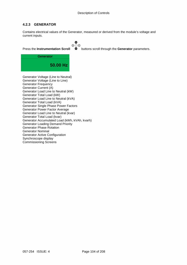
Description of Controls
057-254 ISSUE: 4 Page 104 of 208
4.2.3 GENERATOR Contains electrical values of the Generator, measured or derived from the module’s voltage and current inputs.
Press the Instrumentation Scroll buttons scroll through the Generator parameters.
Generator
50.00 Hz
Generator Voltage (Line to Neutral) Generator Voltage (Line to Line) Generator Frequency Generator Current (A) Generator Load Line to Neutral (kW) Generator Total Load (kW) Generator Load Line to Neutral (kVA) Generator Total Load (kVA) Generator Single Phase Power Factors Generator Power Factor Average Generator Load Line to Neutral (kvar) Generator Total Load (kvar) Generator Accumulated Load (kWh, kVAh, kvarh) Generator Loading Demand Priority Generator Phase Rotation Generator Nominal Generator Active Configuration Synchroscope display Commissioning Screens
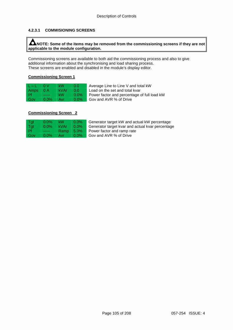
Description of Controls
Page 105 of 208 057-254 ISSUE: 4
4.2.3.1 COMMISIONING SCREENS
NOTE: Some of the items may be removed from the com missioning screens if they are not applicable to the module configuration. Commissioning screens are available to both aid the commissioning process and also to give additional information about the synchronising and load sharing process. These screens are enabled and disabled in the module’s display editor. Commissioning Screen 1 L – L 0 V kW 0.0 Average Line to Line V and total kW Amps 0 A kVAr 0.0 Load on the set and total kvar Pf ----- kW 0.0% Power factor and percentage of full load kW Gov 0.0% Avr 0.0% Gov and AVR % of Drive Commissioning Screen 2 Tgt 0.0% kW 0.0% Generator target kW and actual kW percentage Tgt 0.0% kVAr 0.0% Generator target kvar and actual kvar percentage Pf ----- Ramp 5.0% Power factor and ramp rate Gov 0.0% Avr 0.0% Gov and AVR % of Drive
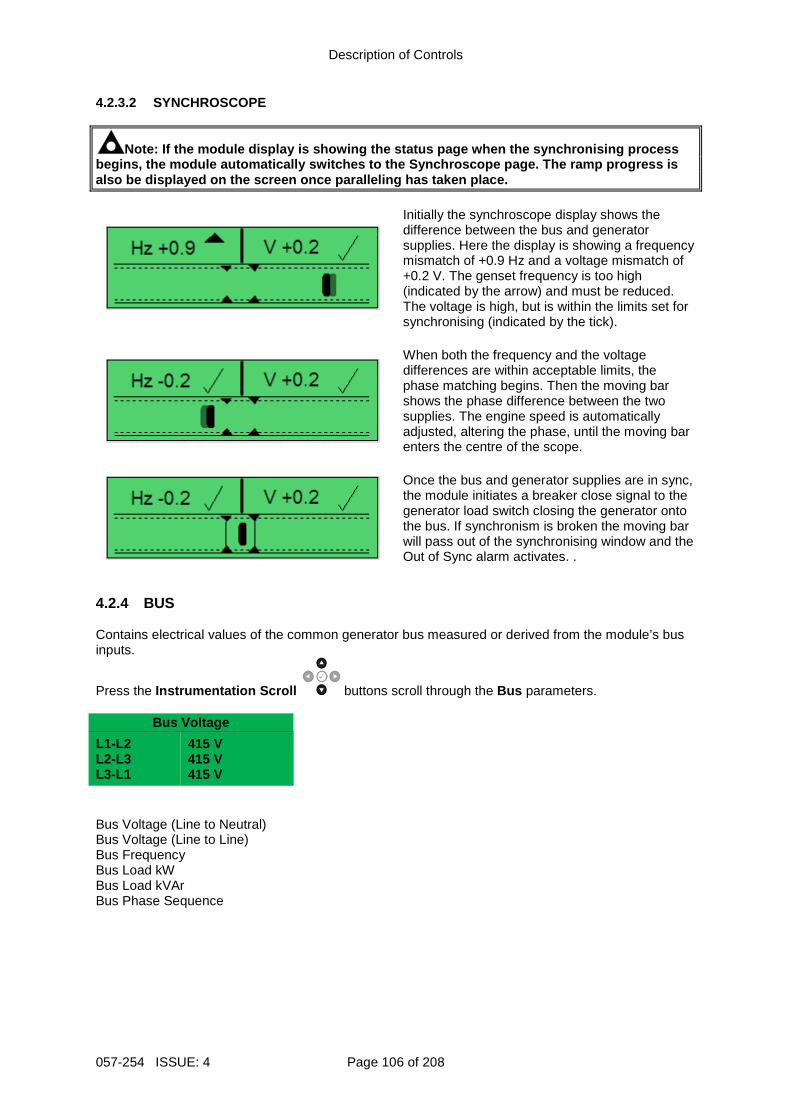
Description of Controls
057-254 ISSUE: 4 Page 106 of 208
4.2.3.2 SYNCHROSCOPE
Note: If the module display is showing the status p age when the synchronising process begins, the module automatically switches to the Sy nchroscope page. The ramp progress is also be displayed on the screen once paralleling ha s taken place.
Initially the synchroscope display shows the difference between the bus and generator supplies. Here the display is showing a frequency mismatch of +0.9 Hz and a voltage mismatch of +0.2 V. The genset frequency is too high (indicated by the arrow) and must be reduced. The voltage is high, but is within the limits set for synchronising (indicated by the tick).
When both the frequency and the voltage differences are within acceptable limits, the phase matching begins. Then the moving bar shows the phase difference between the two supplies. The engine speed is automatically adjusted, altering the phase, until the moving bar enters the centre of the scope.
Once the bus and generator supplies are in sync, the module initiates a breaker close signal to the generator load switch closing the generator onto the bus. If synchronism is broken the moving bar will pass out of the synchronising window and the Out of Sync alarm activates. .
4.2.4 BUS Contains electrical values of the common generator bus measured or derived from the module’s bus inputs.
Press the Instrumentation Scroll buttons scroll through the Bus parameters.
Bus Voltage
L1-L2 L2-L3 L3-L1
415 V 415 V 415 V
Bus Voltage (Line to Neutral) Bus Voltage (Line to Line) Bus Frequency Bus Load kW Bus Load kVAr Bus Phase Sequence
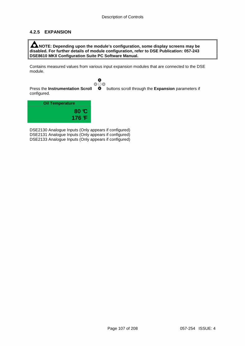
Description of Controls
Page 107 of 208 057-254 ISSUE: 4
4.2.5 EXPANSION
NOTE: Depending upon the module’s configuration, so me display screens may be disabled. For further details of module configurati on, refer to DSE Publication: 057-243 DSE8610 MKII Configuration Suite PC Software Manual . Contains measured values from various input expansion modules that are connected to the DSE module.
Press the Instrumentation Scroll buttons scroll through the Expansion parameters if configured.
Oil Temperature
80 °C 176 °F
DSE2130 Analogue Inputs (Only appears if configured) DSE2131 Analogue Inputs (Only appears if configured) DSE2133 Analogue Inputs (Only appears if configured)
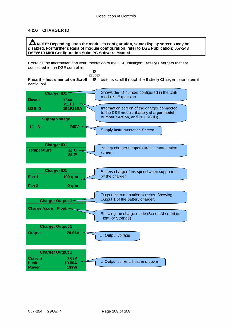
Description of Controls
057-254 ISSUE: 4 Page 108 of 208
4.2.6 CHARGER ID
NOTE: Depending upon the module’s configuration, so me display screens may be disabled. For further details of module configurati on, refer to DSE Publication: 057-243 DSE8610 MKII Configuration Suite PC Software Manual . Contains the information and instrumentation of the DSE Intelligent Battery Chargers that are connected to the DSE controller.
Press the Instrumentation Scroll buttons scroll through the Battery Charger parameters if configured.
Charger ID1 .
Device 94xx V1.1.1
USB ID 1E1F21EA
Supply Voltage
L1 - N 240V
Charger ID1
Temperature 32 °C 89 °F
Charger ID1
Fan 1 100 rpm Fan 2 0 rpm
Charger Output 1
Charge Mode Float
Charger Output 1
Output 26.91V
Charger Output 1
Current 7.05A Limit 10.00A Power 189W
Shows the ID number configured in the DSE module’s Expansion
Information screen of the charger connected to the DSE module (battery charger model number, version, and its USB ID).
Supply Instrumentation Screen.
Battery charger temperature instrumentation screen.
Battery charger fans speed when supported by the charger.
Output Instrumentation screens. Showing Output 1 of the battery charger.
…Output current, limit, and power
… Output voltage
Showing the charge mode (Boost, Absorption, Float, or Storage)
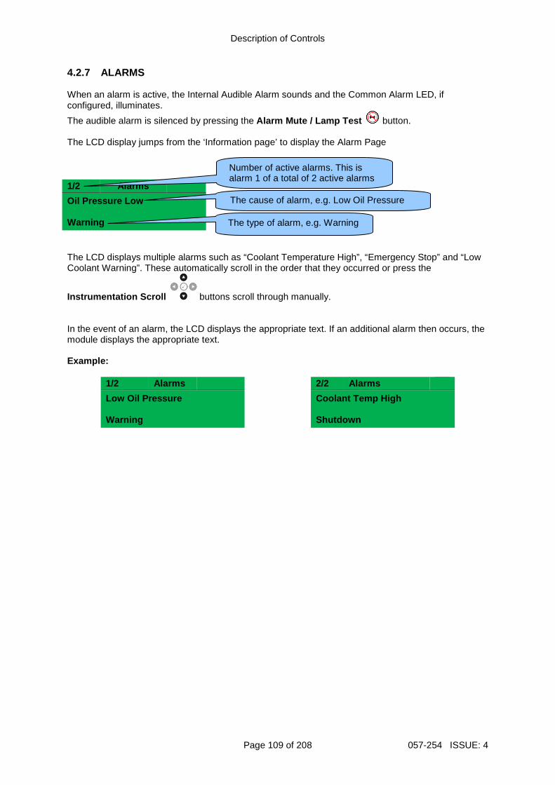
Description of Controls
Page 109 of 208 057-254 ISSUE: 4
4.2.7 ALARMS When an alarm is active, the Internal Audible Alarm sounds and the Common Alarm LED, if configured, illuminates.
The audible alarm is silenced by pressing the Alarm Mute / Lamp Test button. The LCD display jumps from the ‘Information page’ to display the Alarm Page 1/2 Alarms
Oil Pressure Low Warning The LCD displays multiple alarms such as “Coolant Temperature High”, “Emergency Stop” and “Low Coolant Warning”. These automatically scroll in the order that they occurred or press the
Instrumentation Scroll buttons scroll through manually. In the event of an alarm, the LCD displays the appropriate text. If an additional alarm then occurs, the module displays the appropriate text. Example:
1/2 Alarms 2/2 Alarms
Low Oil Pressure Warning
Coolant Temp High Shutdown
The type of alarm, e.g. Warning
The cause of alarm, e.g. Low Oil Pressure
Number of active alarms. This is alarm 1 of a total of 2 active alarms
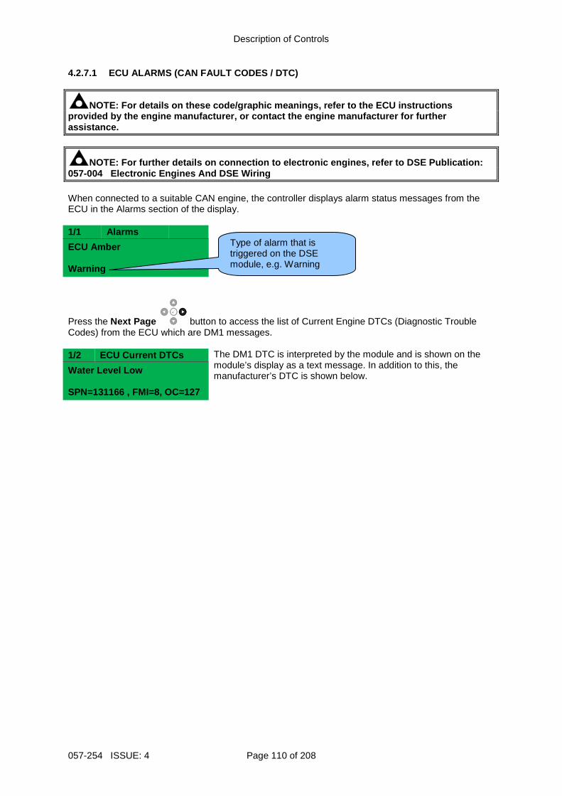
Description of Controls
057-254 ISSUE: 4 Page 110 of 208
4.2.7.1 ECU ALARMS (CAN FAULT CODES / DTC)
NOTE: For details on these code/graphic meanings, r efer to the ECU instructions provided by the engine manufacturer, or contact the engine manufacturer for further assistance.
NOTE: For further details on connection to electron ic engines, refer to DSE Publication: 057-004 Electronic Engines And DSE Wiring When connected to a suitable CAN engine, the controller displays alarm status messages from the ECU in the Alarms section of the display. 1/1 Alarms
ECU Amber Warning
Press the Next Page button to access the list of Current Engine DTCs (Diagnostic Trouble Codes) from the ECU which are DM1 messages. 1/2 ECU Current DTCs The DM1 DTC is interpreted by the module and is shown on the
module’s display as a text message. In addition to this, the manufacturer’s DTC is shown below. Water Level Low
SPN=131166 , FMI=8, OC=127
Type of alarm that is triggered on the DSE module, e.g. Warning
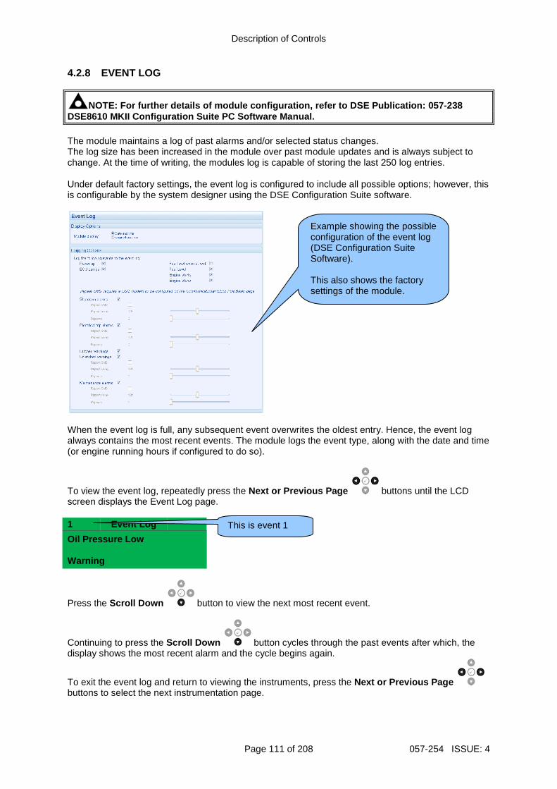
Description of Controls
Page 111 of 208 057-254 ISSUE: 4
4.2.8 EVENT LOG
NOTE: For further details of module configuration, refer to DSE Publication: 057-238 DSE8610 MKII Configuration Suite PC Software Manual . The module maintains a log of past alarms and/or selected status changes. The log size has been increased in the module over past module updates and is always subject to change. At the time of writing, the modules log is capable of storing the last 250 log entries. Under default factory settings, the event log is configured to include all possible options; however, this is configurable by the system designer using the DSE Configuration Suite software.
When the event log is full, any subsequent event overwrites the oldest entry. Hence, the event log always contains the most recent events. The module logs the event type, along with the date and time (or engine running hours if configured to do so).
To view the event log, repeatedly press the Next or Previous Page buttons until the LCD screen displays the Event Log page. 1 Event Log
Oil Pressure Low Warning
Press the Scroll Down button to view the next most recent event.
Continuing to press the Scroll Down button cycles through the past events after which, the display shows the most recent alarm and the cycle begins again.
To exit the event log and return to viewing the instruments, press the Next or Previous Page buttons to select the next instrumentation page.
Example showing the possible configuration of the event log (DSE Configuration Suite Software). This also shows the factory settings of the module.
This is event 1
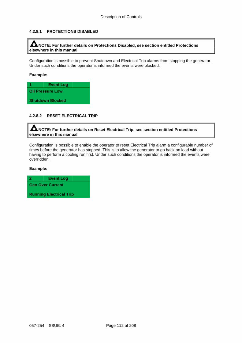
Description of Controls
057-254 ISSUE: 4 Page 112 of 208
4.2.8.1 PROTECTIONS DISABLED
NOTE: For further details on Protections Disabled , see section entitled Protections elsewhere in this manual. Configuration is possible to prevent Shutdown and Electrical Trip alarms from stopping the generator. Under such conditions the operator is informed the events were blocked. Example: 1 Event Log
Oil Pressure Low Shutdown Blocked 4.2.8.2 RESET ELECTRICAL TRIP
NOTE: For further details on Reset Electrical Trip , see section entitled Protections elsewhere in this manual. Configuration is possible to enable the operator to reset Electrical Trip alarm a configurable number of times before the generator has stopped. This is to allow the generator to go back on load without having to perform a cooling run first. Under such conditions the operator is informed the events were overridden. Example: 2 Event Log
Gen Over Current Running Electrical Trip
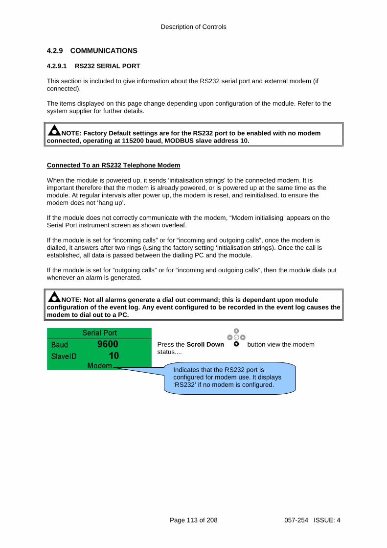
Description of Controls
Page 113 of 208 057-254 ISSUE: 4
4.2.9 COMMUNICATIONS 4.2.9.1 RS232 SERIAL PORT This section is included to give information about the RS232 serial port and external modem (if connected). The items displayed on this page change depending upon configuration of the module. Refer to the system supplier for further details.
NOTE: Factory Default settings are for the RS232 po rt to be enabled with no modem connected, operating at 115200 baud, MODBUS slave a ddress 10. Connected To an RS232 Telephone Modem When the module is powered up, it sends ‘initialisation strings’ to the connected modem. It is important therefore that the modem is already powered, or is powered up at the same time as the module. At regular intervals after power up, the modem is reset, and reinitialised, to ensure the modem does not ‘hang up’. If the module does not correctly communicate with the modem, “Modem initialising’ appears on the Serial Port instrument screen as shown overleaf. If the module is set for “incoming calls” or for “incoming and outgoing calls”, once the modem is dialled, it answers after two rings (using the factory setting ‘initialisation strings). Once the call is established, all data is passed between the dialling PC and the module. If the module is set for “outgoing calls” or for “incoming and outgoing calls”, then the module dials out whenever an alarm is generated.
NOTE: Not all alarms generate a dial out command; t his is dependant upon module configuration of the event log. Any event configure d to be recorded in the event log causes the modem to dial out to a PC.
Press the Scroll Down button view the modem status....
Indicates that the RS232 port is configured for modem use. It displays ‘RS232’ if no modem is configured.
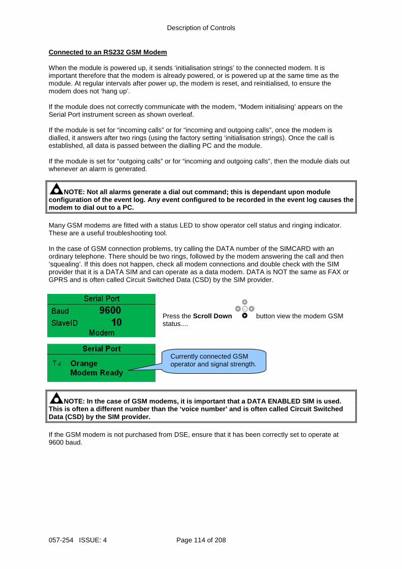
Description of Controls
057-254 ISSUE: 4 Page 114 of 208
Connected to an RS232 GSM Modem When the module is powered up, it sends ‘initialisation strings’ to the connected modem. It is important therefore that the modem is already powered, or is powered up at the same time as the module. At regular intervals after power up, the modem is reset, and reinitialised, to ensure the modem does not ‘hang up’. If the module does not correctly communicate with the modem, “Modem initialising’ appears on the Serial Port instrument screen as shown overleaf. If the module is set for “incoming calls” or for “incoming and outgoing calls”, once the modem is dialled, it answers after two rings (using the factory setting ‘initialisation strings). Once the call is established, all data is passed between the dialling PC and the module. If the module is set for “outgoing calls” or for “incoming and outgoing calls”, then the module dials out whenever an alarm is generated.
NOTE: Not all alarms generate a dial out command; t his is dependant upon module configuration of the event log. Any event configure d to be recorded in the event log causes the modem to dial out to a PC. Many GSM modems are fitted with a status LED to show operator cell status and ringing indicator. These are a useful troubleshooting tool. In the case of GSM connection problems, try calling the DATA number of the SIMCARD with an ordinary telephone. There should be two rings, followed by the modem answering the call and then ‘squealing’. If this does not happen, check all modem connections and double check with the SIM provider that it is a DATA SIM and can operate as a data modem. DATA is NOT the same as FAX or GPRS and is often called Circuit Switched Data (CSD) by the SIM provider.
Press the Scroll Down button view the modem GSM status....
NOTE: In the case of GSM modems, it is important th at a DATA ENABLED SIM is used. This is often a different number than the ‘voice nu mber’ and is often called Circuit Switched Data (CSD) by the SIM provider. If the GSM modem is not purchased from DSE, ensure that it has been correctly set to operate at 9600 baud.
Currently connected GSM operator and signal strength.
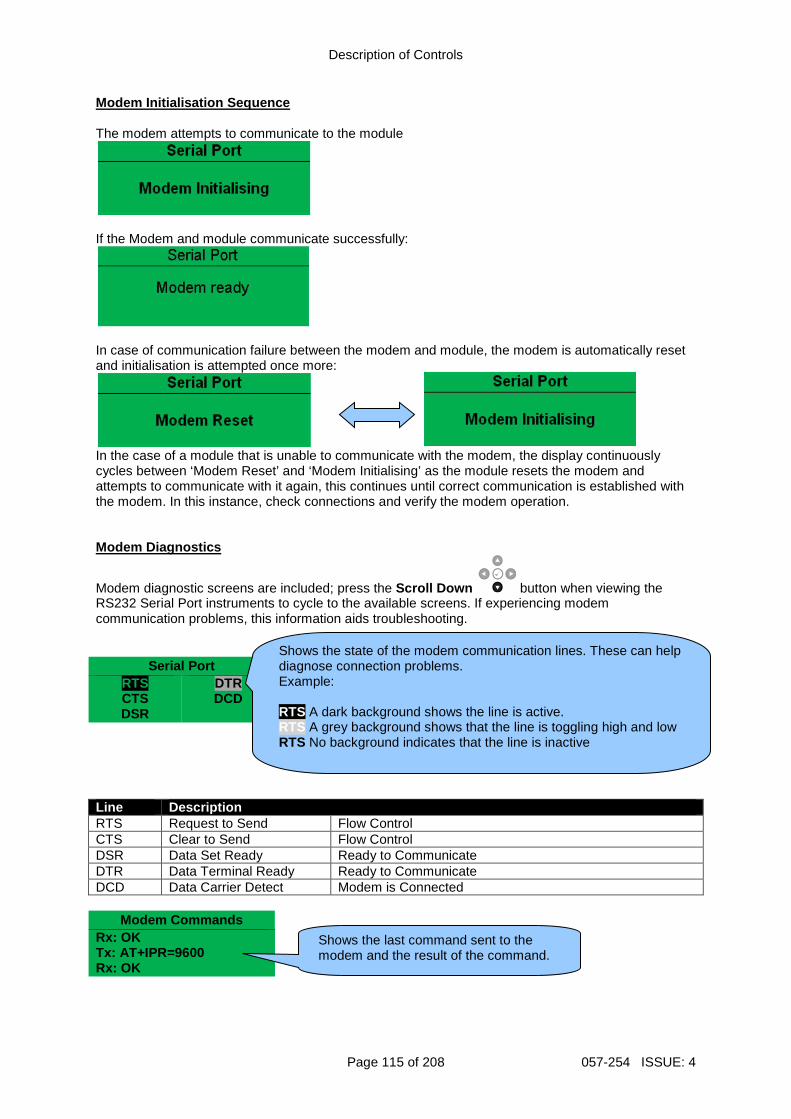
Description of Controls
Page 115 of 208 057-254 ISSUE: 4
Modem Initialisation Sequence The modem attempts to communicate to the module
If the Modem and module communicate successfully:
In case of communication failure between the modem and module, the modem is automatically reset and initialisation is attempted once more:
In the case of a module that is unable to communicate with the modem, the display continuously cycles between ‘Modem Reset’ and ‘Modem Initialising’ as the module resets the modem and attempts to communicate with it again, this continues until correct communication is established with the modem. In this instance, check connections and verify the modem operation. Modem Diagnostics
Modem diagnostic screens are included; press the Scroll Down button when viewing the RS232 Serial Port instruments to cycle to the available screens. If experiencing modem communication problems, this information aids troubleshooting.
Serial Port RTS CTS DSR
DTR DCD
Line Description RTS Request to Send Flow Control CTS Clear to Send Flow Control DSR Data Set Ready Ready to Communicate DTR Data Terminal Ready Ready to Communicate DCD Data Carrier Detect Modem is Connected
Modem Commands Rx: OK Tx: AT+IPR=9600 Rx: OK
Shows the state of the modem communication lines. These can help diagnose connection problems. Example: RTS A dark background shows the line is active. RTS A grey background shows that the line is toggling high and low RTS No background indicates that the line is inactive
Shows the last command sent to the modem and the result of the command.
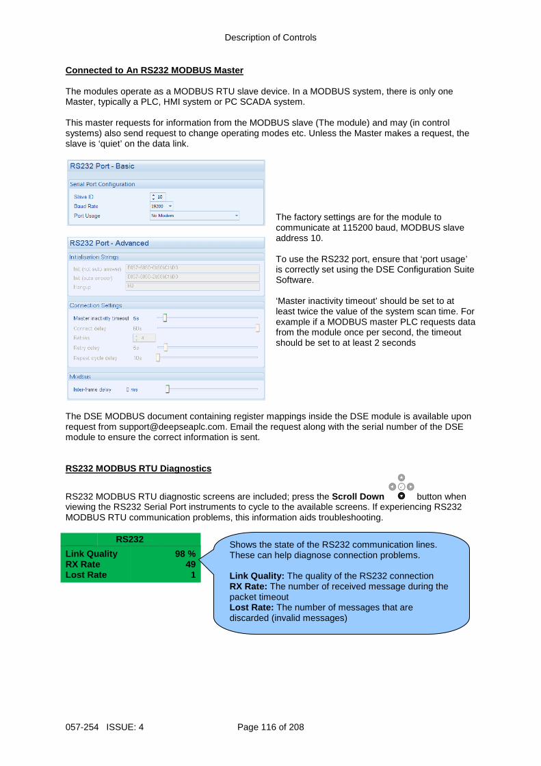
Description of Controls
057-254 ISSUE: 4 Page 116 of 208
Connected to An RS232 MODBUS Master The modules operate as a MODBUS RTU slave device. In a MODBUS system, there is only one Master, typically a PLC, HMI system or PC SCADA system. This master requests for information from the MODBUS slave (The module) and may (in control systems) also send request to change operating modes etc. Unless the Master makes a request, the slave is ‘quiet’ on the data link.
The factory settings are for the module to communicate at 115200 baud, MODBUS slave address 10. To use the RS232 port, ensure that ‘port usage’ is correctly set using the DSE Configuration Suite Software. ‘Master inactivity timeout’ should be set to at least twice the value of the system scan time. For example if a MODBUS master PLC requests data from the module once per second, the timeout should be set to at least 2 seconds
The DSE MODBUS document containing register mappings inside the DSE module is available upon request from [email protected]. Email the request along with the serial number of the DSE module to ensure the correct information is sent. RS232 MODBUS RTU Diagnostics
RS232 MODBUS RTU diagnostic screens are included; press the Scroll Down button when viewing the RS232 Serial Port instruments to cycle to the available screens. If experiencing RS232 MODBUS RTU communication problems, this information aids troubleshooting.
RS232
Link Quality RX Rate Lost Rate
98 % 49
1
Shows the state of the RS232 communication lines. These can help diagnose connection problems. Link Quality: The quality of the RS232 connection RX Rate: The number of received message during the packet timeout Lost Rate: The number of messages that are discarded (invalid messages)
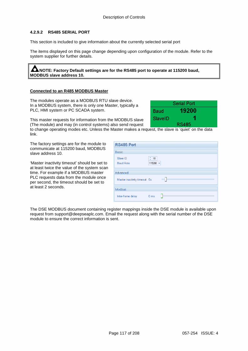
Description of Controls
Page 117 of 208 057-254 ISSUE: 4
4.2.9.2 RS485 SERIAL PORT This section is included to give information about the currently selected serial port The items displayed on this page change depending upon configuration of the module. Refer to the system supplier for further details.
NOTE: Factory Default settings are for the RS485 po rt to operate at 115200 baud, MODBUS slave address 10. Connected to an R485 MODBUS Master The modules operate as a MODBUS RTU slave device. In a MODBUS system, there is only one Master, typically a PLC, HMI system or PC SCADA system. This master requests for information from the MODBUS slave (The module) and may (in control systems) also send request to change operating modes etc. Unless the Master makes a request, the slave is ‘quiet’ on the data link. The factory settings are for the module to communicate at 115200 baud, MODBUS slave address 10. ‘Master inactivity timeout’ should be set to at least twice the value of the system scan time. For example if a MODBUS master PLC requests data from the module once per second, the timeout should be set to at least 2 seconds.
The DSE MODBUS document containing register mappings inside the DSE module is available upon request from [email protected]. Email the request along with the serial number of the DSE module to ensure the correct information is sent.
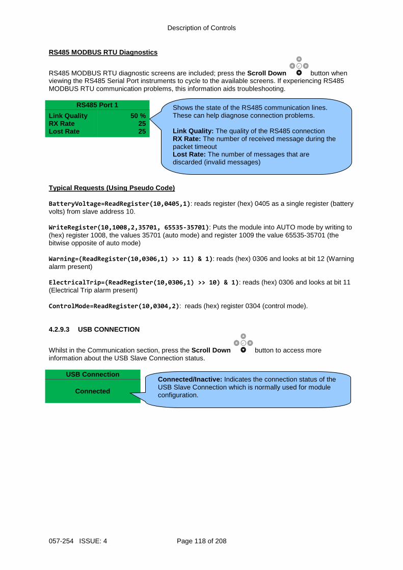
Description of Controls
057-254 ISSUE: 4 Page 118 of 208
RS485 MODBUS RTU Diagnostics
RS485 MODBUS RTU diagnostic screens are included; press the Scroll Down button when viewing the RS485 Serial Port instruments to cycle to the available screens. If experiencing RS485 MODBUS RTU communication problems, this information aids troubleshooting.
RS485 Port 1
Link Quality RX Rate Lost Rate
50 % 25 25
Typical Requests (Using Pseudo Code) BatteryVoltage=ReadRegister(10,0405,1): reads register (hex) 0405 as a single register (battery volts) from slave address 10. WriteRegister(10,1008,2,35701, 65535-35701): Puts the module into AUTO mode by writing to (hex) register 1008, the values 35701 (auto mode) and register 1009 the value 65535-35701 (the bitwise opposite of auto mode) Warning=(ReadRegister(10,0306,1) >> 11) & 1): reads (hex) 0306 and looks at bit 12 (Warning alarm present) ElectricalTrip=(ReadRegister(10,0306,1) >> 10) & 1): reads (hex) 0306 and looks at bit 11 (Electrical Trip alarm present) ControlMode=ReadRegister(10,0304,2): reads (hex) register 0304 (control mode). 4.2.9.3 USB CONNECTION
Whilst in the Communication section, press the Scroll Down button to access more information about the USB Slave Connection status.
USB Connection Connected
Shows the state of the RS485 communication lines. These can help diagnose connection problems. Link Quality: The quality of the RS485 connection RX Rate: The number of received message during the packet timeout Lost Rate: The number of messages that are discarded (invalid messages)
Connected/Inactive : Indicates the connection status of the USB Slave Connection which is normally used for module configuration.
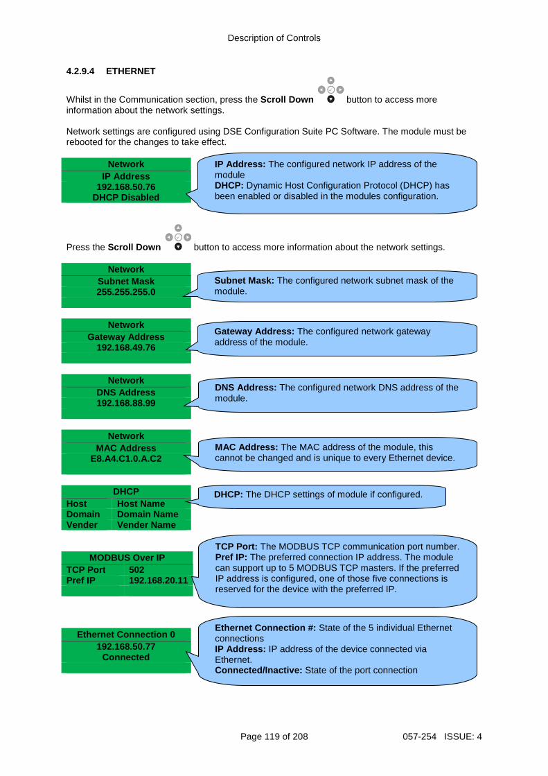
Description of Controls
Page 119 of 208 057-254 ISSUE: 4
4.2.9.4 ETHERNET
Whilst in the Communication section, press the Scroll Down button to access more information about the network settings. Network settings are configured using DSE Configuration Suite PC Software. The module must be rebooted for the changes to take effect.
Network
IP Address 192.168.50.76
DHCP Disabled
Press the Scroll Down button to access more information about the network settings.
Network
Subnet Mask 255.255.255.0
Network
Gateway Address 192.168.49.76
Network
DNS Address 192.168.88.99
Network
MAC Address E8.A4.C1.0.A.C2
DHCP
Host Host Name Domain Domain Name Vender Vender Name
MODBUS Over IP
TCP Port 502 Pref IP 192.168.20.11
Ethernet Connection 0
192.168.50.77 Connected
IP Address: The configured network IP address of the module DHCP: Dynamic Host Configuration Protocol (DHCP) has been enabled or disabled in the modules configuration.
Subnet Mask: The configured network subnet mask of the module.
Gateway Address: The configured network gateway address of the module.
DNS Address: The configured network DNS address of the module.
MAC Address: The MAC address of the module, this cannot be changed and is unique to every Ethernet device.
TCP Port: The MODBUS TCP communication port number. Pref IP: The preferred connection IP address. The module can support up to 5 MODBUS TCP masters. If the preferred IP address is configured, one of those five connections is reserved for the device with the preferred IP.
DHCP: The DHCP settings of module if configured.
Ethernet Connection #: State of the 5 individual Ethernet connections IP Address: IP address of the device connected via Ethernet. Connected/Inactive: State of the port connection
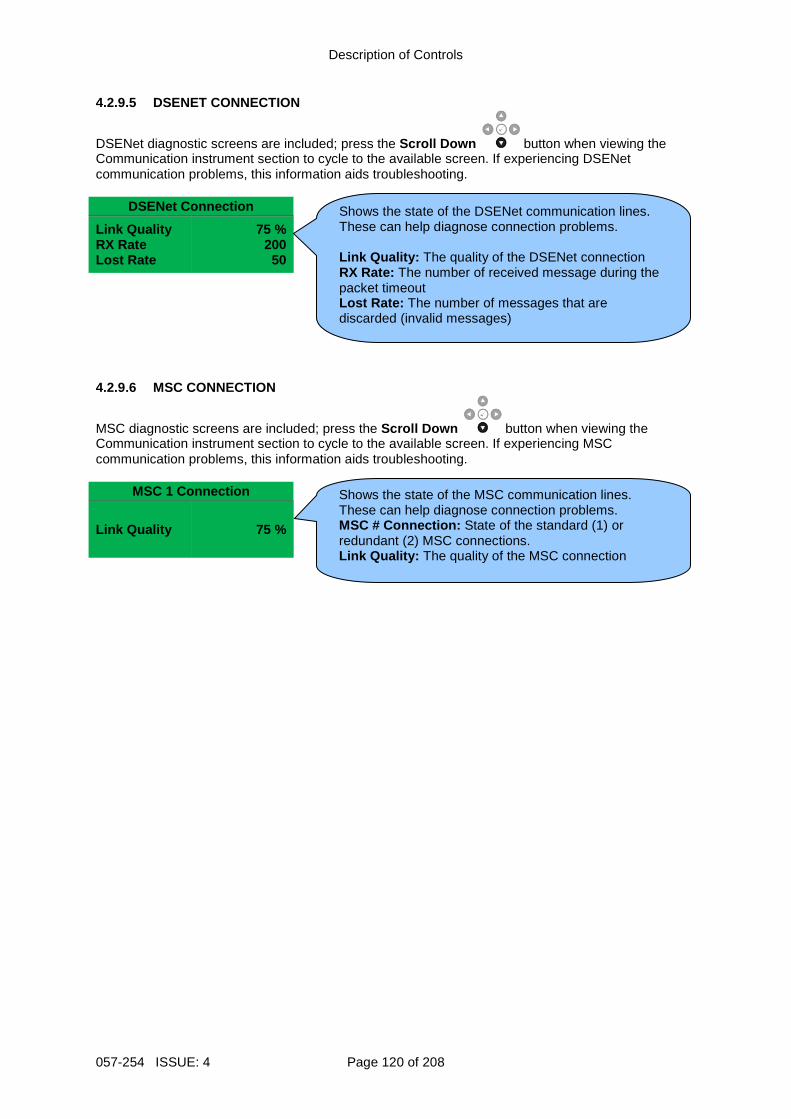
Description of Controls
057-254 ISSUE: 4 Page 120 of 208
4.2.9.5 DSENET CONNECTION
DSENet diagnostic screens are included; press the Scroll Down button when viewing the Communication instrument section to cycle to the available screen. If experiencing DSENet communication problems, this information aids troubleshooting.
DSENet Connection
Link Quality RX Rate Lost Rate
75 % 200 50
4.2.9.6 MSC CONNECTION
MSC diagnostic screens are included; press the Scroll Down button when viewing the Communication instrument section to cycle to the available screen. If experiencing MSC communication problems, this information aids troubleshooting.
MSC 1 Connection
Link Quality 75 %
Shows the state of the DSENet communication lines. These can help diagnose connection problems. Link Quality: The quality of the DSENet connection RX Rate: The number of received message during the packet timeout Lost Rate: The number of messages that are discarded (invalid messages)
Shows the state of the MSC communication lines. These can help diagnose connection problems. MSC # Connection: State of the standard (1) or redundant (2) MSC connections. Link Quality: The quality of the MSC connection
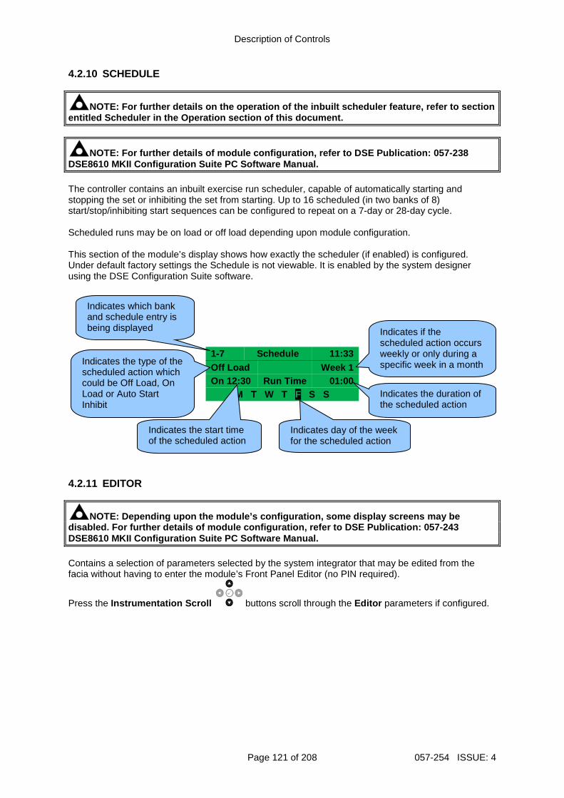
Description of Controls
Page 121 of 208 057-254 ISSUE: 4
4.2.10 SCHEDULE
NOTE: For further details on the operation of the i nbuilt scheduler feature, refer to section entitled Scheduler in the Operation section of this document.
NOTE: For further details of module configuration, refer to DSE Publication: 057-238 DSE8610 MKII Configuration Suite PC Software Manual . The controller contains an inbuilt exercise run scheduler, capable of automatically starting and stopping the set or inhibiting the set from starting. Up to 16 scheduled (in two banks of 8) start/stop/inhibiting start sequences can be configured to repeat on a 7-day or 28-day cycle. Scheduled runs may be on load or off load depending upon module configuration. This section of the module’s display shows how exactly the scheduler (if enabled) is configured. Under default factory settings the Schedule is not viewable. It is enabled by the system designer using the DSE Configuration Suite software.
1-7 Schedule 11:33 Off Load Week 1 On 12:30 Run Time 01:00
M T W T F S S 4.2.11 EDITOR
NOTE: Depending upon the module’s configuration, so me display screens may be disabled. For further details of module configurati on, refer to DSE Publication: 057-243 DSE8610 MKII Configuration Suite PC Software Manual . Contains a selection of parameters selected by the system integrator that may be edited from the facia without having to enter the module’s Front Panel Editor (no PIN required).
Press the Instrumentation Scroll buttons scroll through the Editor parameters if configured.
Indicates day of the week for the scheduled action
Indicates the start time of the scheduled action
Indicates the duration of the scheduled action
Indicates if the scheduled action occurs weekly or only during a specific week in a month
Indicates the type of the scheduled action which could be Off Load, On Load or Auto Start Inhibit
Indicates which bank and schedule entry is being displayed
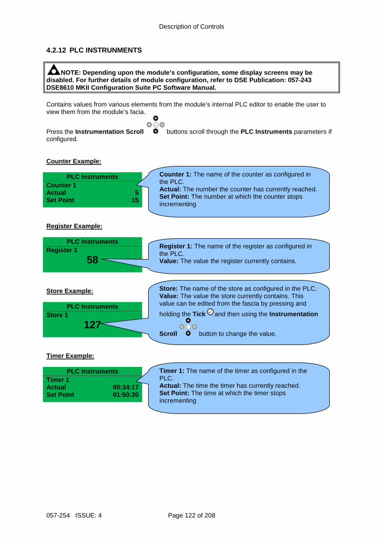
Description of Controls
057-254 ISSUE: 4 Page 122 of 208
4.2.12 PLC INSTRUNMENTS
NOTE: Depending upon the module’s configuration, so me display screens may be disabled. For further details of module configurati on, refer to DSE Publication: 057-243 DSE8610 MKII Configuration Suite PC Software Manual . Contains values from various elements from the module’s internal PLC editor to enable the user to view them from the module’s facia.
Press the Instrumentation Scroll buttons scroll through the PLC Instruments parameters if configured. Counter Example:
PLC Instruments Counter 1 Actual Set Point
5
15
Register Example:
PLC Instruments Register 1
58 Store Example:
PLC Instruments Store 1
127 Timer Example:
PLC Instruments Timer 1 Actual Set Point
00:34:17 01:50:30
Counter 1 : The name of the counter as configured in the PLC. Actual: The number the counter has currently reached. Set Point: The number at which the counter stops incrementing
Register 1 : The name of the register as configured in the PLC. Value: The value the register currently contains.
Store : The name of the store as configured in the PLC. Value: The value the store currently contains. This value can be edited from the fascia by pressing and
holding the Tick and then using the Instrumentation
Scroll button to change the value.
Timer 1 : The name of the timer as configured in the PLC. Actual: The time the timer has currently reached. Set Point: The time at which the timer stops incrementing
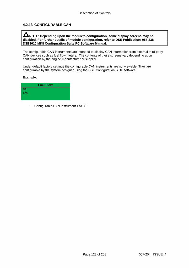
Description of Controls
Page 123 of 208 057-254 ISSUE: 4
4.2.13 CONFIGURABLE CAN
NOTE: Depending upon the module’s configuration, so me display screens may be disabled. For further details of module configurati on, refer to DSE Publication: 057-238 DSE8610 MKII Configuration Suite PC Software Manual . The configurable CAN instruments are intended to display CAN information from external third party CAN devices such as fuel flow meters. The contents of these screens vary depending upon configuration by the engine manufacturer or supplier. Under default factory settings the configurable CAN instruments are not viewable. They are configurable by the system designer using the DSE Configuration Suite software. Example:
Fuel Flow 84 L/h
• Configurable CAN Instrument 1 to 30
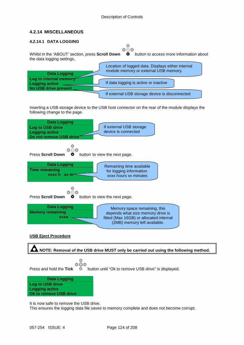
Description of Controls
057-254 ISSUE: 4 Page 124 of 208
4.2.14 MISCELLANEOUS 4.2.14.1 DATA LOGGING
Whilst in the ‘ABOUT’ section, press Scroll Down button to access more information about the data logging settings.
Data Logging
Log to internal memory Logging active No USB drive present Inserting a USB storage device to the USB host connector on the rear of the module displays the following change to the page.
Data Logging
Log to USB drive Logging active Do not remove USB drive
Press Scroll Down button to view the next page.
Data Logging Time remaining xxxx h xx m
Press Scroll Down button to view the next page.
Data Logging
Memory remaining xxxx
USB Eject Procedure
NOTE: Removal of the USB drive MUST only be carrie d out using the following method.
Press and hold the Tick button until “Ok to remove USB drive” is displayed.
Data Logging
Log to USB drive Logging active Ok to remove USB drive It is now safe to remove the USB drive. This ensures the logging data file saves to memory complete and does not become corrupt.
Location of logged data. Displays either internal module memory or external USB memory.
If data logging is active or inactive
If external USB storage device is disconnected
If external USB storage device is connected
Remaining time available for logging information. xxxx hours xx minutes
Memory space remaining, this depends what size memory drive is
fitted (Max 16GB) or allocated internal (2MB) memory left available.
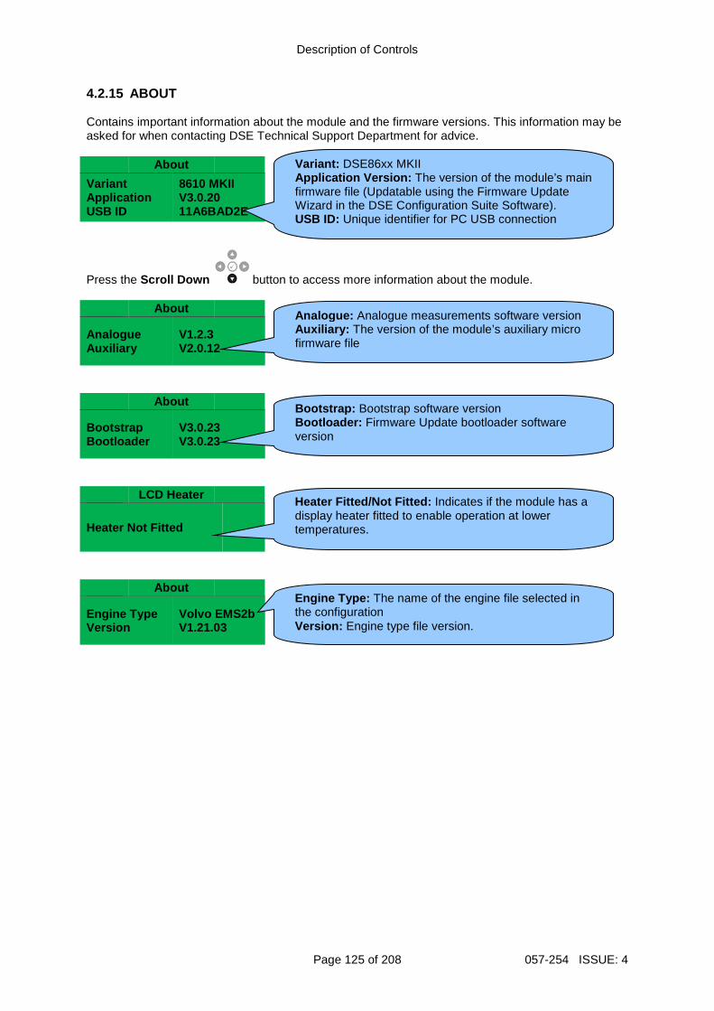
Description of Controls
Page 125 of 208 057-254 ISSUE: 4
4.2.15 ABOUT Contains important information about the module and the firmware versions. This information may be asked for when contacting DSE Technical Support Department for advice.
About
Variant Application USB ID
8610 MKII V3.0.20 11A6BAD2E
Press the Scroll Down button to access more information about the module.
About
Analogue Auxiliary
V1.2.3 V2.0.12
About
Bootstrap Bootloader
V3.0.23 V3.0.23
LCD Heater
Heater Not Fitted
About
Engine Type Version
Volvo EMS2b V1.21.03
Variant: DSE86xx MKII Application Version: The version of the module’s main firmware file (Updatable using the Firmware Update Wizard in the DSE Configuration Suite Software). USB ID: Unique identifier for PC USB connection
Analogue: Analogue measurements software version Auxiliary: The version of the module’s auxiliary micro firmware file
Engine Type: The name of the engine file selected in the configuration Version: Engine type file version.
Heater Fitted/Not Fitted: Indicates if the module has a display heater fitted to enable operation at lower temperatures.
Bootstrap: Bootstrap software version Bootloader: Firmware Update bootloader software version
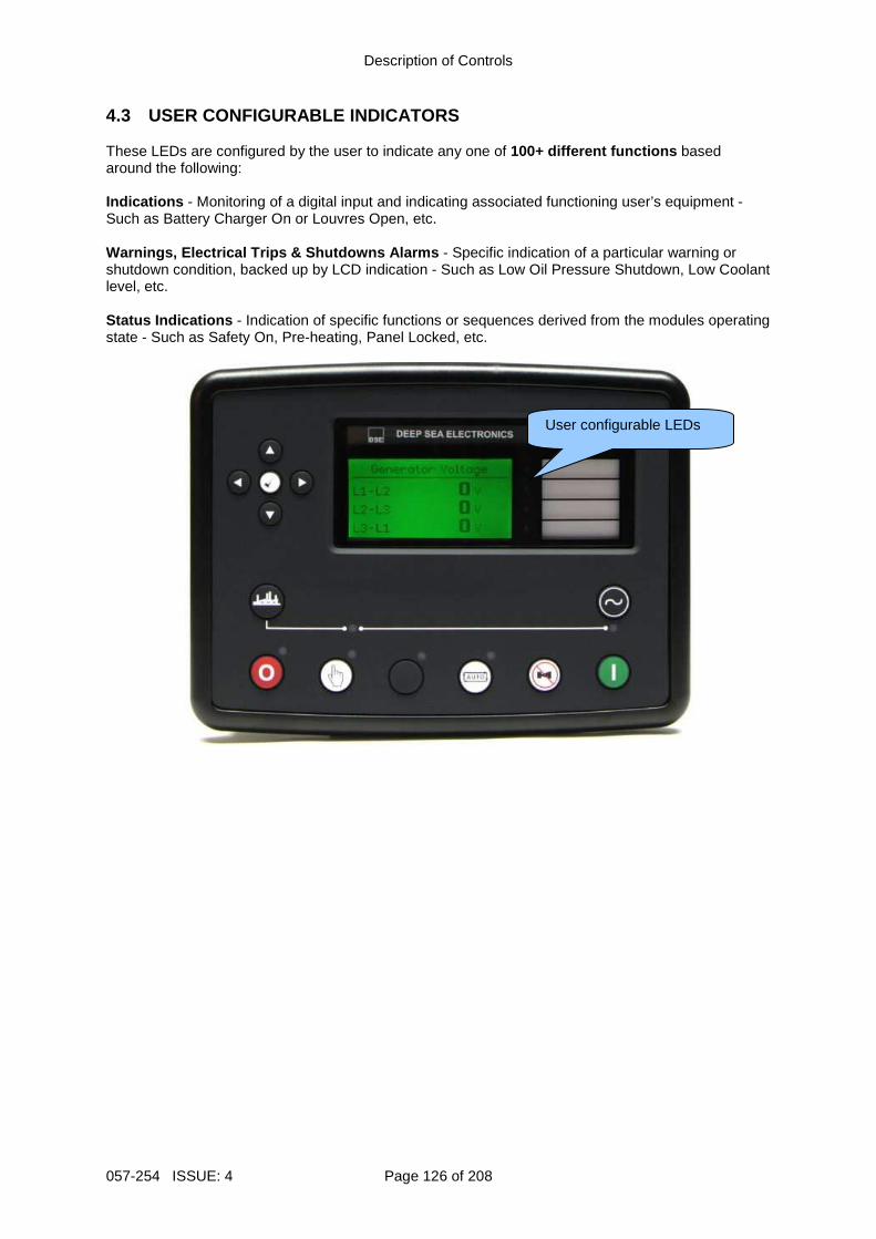
Description of Controls
057-254 ISSUE: 4 Page 126 of 208
4.3 USER CONFIGURABLE INDICATORS These LEDs are configured by the user to indicate any one of 100+ different functions based around the following: Indications - Monitoring of a digital input and indicating associated functioning user’s equipment - Such as Battery Charger On or Louvres Open, etc. Warnings, Electrical Trips & Shutdowns Alarms - Specific indication of a particular warning or shutdown condition, backed up by LCD indication - Such as Low Oil Pressure Shutdown, Low Coolant level, etc. Status Indications - Indication of specific functions or sequences derived from the modules operating state - Such as Safety On, Pre-heating, Panel Locked, etc.
User configurable LEDs
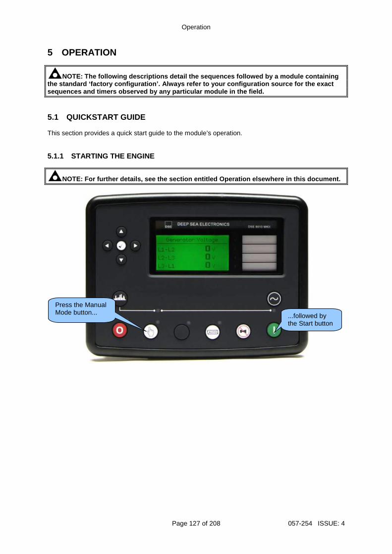
Operation
Page 127 of 208 057-254 ISSUE: 4
5 OPERATION
NOTE: The following descriptions detail the sequenc es followed by a module containing the standard ‘factory configuration’. Always refer to your configuration source for the exact sequences and timers observed by any particular mod ule in the field. 5.1 QUICKSTART GUIDE This section provides a quick start guide to the module’s operation. 5.1.1 STARTING THE ENGINE
NOTE: For further details, see the section entitled Operation elsewhere in this document.
...followed by the Start button
Press the Manual Mode button...
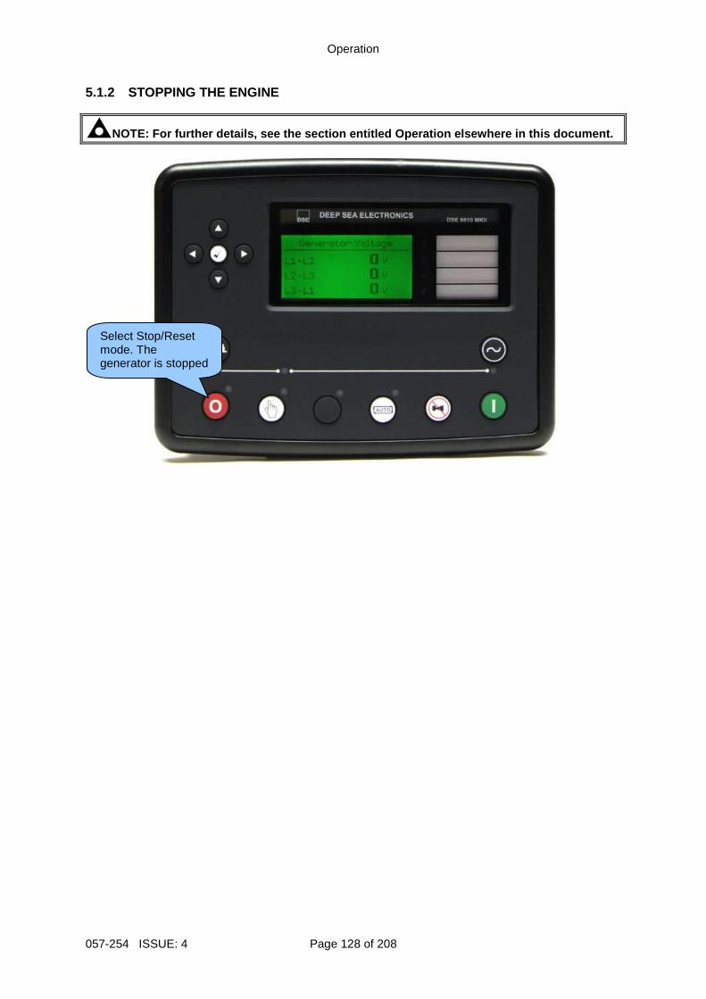
Operation
057-254 ISSUE: 4 Page 128 of 208
5.1.2 STOPPING THE ENGINE
NOTE: For further details, see the section entitled Operation elsewhere in this document.
Select Stop/Reset mode. The generator is stopped
Operation
Page 129 of 208 057-254 ISSUE: 4
5.2 STOP/RESET MODE
NOTE: If a digital input configured to Panel Lock is active, changing module modes is not possible. Viewing the instruments and event logs is NOT affected by Panel Lock .
NOTE: For further details of module configuration, refer to DSE Publication: 057-238 DSE8610 MKII Configuration Suite PC Software Manual .
Stop/Reset Mode is activated by pressing the Stop/Reset Mode button.
The LED above the Stop/Reset Mode button illuminates to indicate Stop/Reset Mode operation.
In Stop/Reset Mode , the module removes the generator from load (if necessary) before stopping the generator. If the generator does not stop when requested, the Fail To Stop alarm is activated (subject to the setting of the Fail to Stop timer). To detect the engine at rest the following must occur:
• Engine speed is zero as detected by the CAN ECU • Generator AC Voltage and Frequency must be zero. • Engine Charge Alternator Voltage must be zero. • Oil pressure sensor must indicate low oil pressure
When the engine has stopped and the module is in the Stop/Reset Mode , it is possible to send configuration files to the module from DSE Configuration Suite PC software and to enter the Front Panel Editor to change parameters.
Any latched alarms that have been cleared are reset when Stop/Reset Mode is entered.
The engine is not started when in Stop/Reset Mode . If start signals are given, the input is
ignored until Auto Mode is entered.
When left in Stop/Reset Mode with no presses of the fascia buttons, no form of communication active and configured for Power Save Mode, the module enters Power Save Mode. To ‘wake’ the module, press any fascia control buttons.
5.2.1 ECU OVERRIDE
Pressing the Start button in Stop/Reset Mode powers up the engine’s ECU but does not start the engine. This can be used to check the status of the CAN communication and to prime the fuel system.
Power Save Mode in the DSE Configuration Suite Software
Operation
057-254 ISSUE: 4 Page 130 of 208
5.3 MANUAL MODE
NOTE: If a digital input configured to Panel Lock i s active, changing module modes is not possible. Viewing the instruments and event logs is NOT affected by panel lock.
Manual Mode is activated by pressing the Manual Mode button.
The LED above the Manual Mode button illuminates to indicate Manual Mode operations.
In Manual Mode the generator does not start automatically
To begin the starting sequence, press the Start button. 5.3.1 STARTING SEQUENCE
NOTE: There is no Start Delay in this mode of operation.
NOTE: If the unit has been configured for CAN, comp atible ECU’s receives the start command via CAN.
NOTE: For further details of module configuration, refer to DSE Publication: 057-238 DSE8610 MKII Configuration Suite PC Software Manual . The fuel relay is energised and the engine is cranked. If the engine fails to fire during this cranking attempt then the starter motor is disengaged for the Crank Rest Timer duration after which the next start attempt is made. Should this sequence continue beyond the set Number Of Attempts, the start sequence is terminated and the display shows Fail to Start. The starter motor is disengaged when the engine fires. Speed detection is factory configured to be derived from the AC alternator output frequency, but can additionally be measured from a Magnetic Pickup mounted on the flywheel or from the CANbus link to the engine ECU depending on module configuration. Additionally, rising oil pressure can be used to disconnect the starter motor (but cannot detect underspeed or overspeed). After the starter motor has disengaged, the Safety On Delay timer activates, allowing Oil Pressure, High Engine Temperature, Under-speed, Charge Fail and any delayed Auxiliary fault inputs to stabilise without triggering the fault.
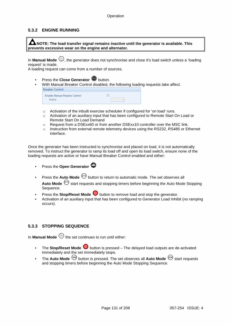
Operation
Page 131 of 208 057-254 ISSUE: 4
5.3.2 ENGINE RUNNING
NOTE: The load transfer signal remains inactive unt il the generator is available. This prevents excessive wear on the engine and alternato r.
In Manual Mode , the generator does not synchronise and close it’s load switch unless a ‘loading request’ is made. A loading request can come from a number of sources.
• Press the Close Generator button. • With Manual Breaker Control disabled, the following loading requests take affect.
o Activation of the inbuilt exercise scheduler if configured for ‘on load’ runs. o Activation of an auxiliary input that has been configured to Remote Start On Load or
Remote Start On Load Demand o Request from a DSExx60 or from another DSExx10 controller over the MSC link. o Instruction from external remote telemetry devices using the RS232, RS485 or Ethernet
interface. Once the generator has been instructed to synchronise and placed on load, it is not automatically removed. To instruct the generator to ramp its load off and open its load switch, ensure none of the loading requests are active or have Manual Breaker Control enabled and either:
• Press the Open Generator
• Press the Auto Mode button to return to automatic mode. The set observes all
Auto Mode start requests and stopping timers before beginning the Auto Mode Stopping Sequence.
• Press the Stop/Reset Mode button to remove load and stop the generator. • Activation of an auxiliary input that has been configured to Generator Load Inhibit (no ramping
occurs). 5.3.3 STOPPING SEQUENCE
In Manual Mode the set continues to run until either:
• The Stop/Reset Mode button is pressed – The delayed load outputs are de-activated immediately and the set immediately stops.
• The Auto Mode button is pressed. The set observes all Auto Mode start requests and stopping timers before beginning the Auto Mode Stopping Sequence.
Operation
057-254 ISSUE: 4 Page 132 of 208
5.4 AUTOMATIC MODE
NOTE: If a digital input configured to external Panel Pock is active, changing module modes is not possible. Viewing the instruments and event logs is NOT affected by Panel Lock .
Auto Mode is activated by pressing the Auto Mode button.
The LED above the Auto Mode button illuminates to indicate Auto Mode operations.
Auto Mode allows the generator to operate fully automatically, starting and stopping as required with no user intervention. 5.4.1 WAITING IN AUTO MODE If a starting request is made, the starting sequence begins. Starting requests can be from the following sources:
• Activation of the inbuilt exercise scheduler. • Activation of an auxiliary input that has been configured to Remote Start On Load, Remote
Start On Load Demand or Remote Start Off Load. • Request from a DSExx60 or from another DSExx10 controller over the MSC link. • Instruction from external remote telemetry devices using the RS232, RS485 or Ethernet
interface. 5.4.2 STARTING SEQUENCE
NOTE: If the unit has been configured for CAN, comp atible ECU’s receive the start command via CAN and transmit the engine speed to th e DSE controller.
NOTE: For further details of module configuration, refer to DSE Publication: 057-238 DSE8610 MKII Configuration Suite PC Software Manual . To allow for ‘false’ start requests, the Start Delay timer begins. Should all start requests be removed during the Start Delay timer, the unit returns to a stand-by state. If a start request is still present at the end of the Start Delay timer, the fuel relay is energised and the engine is cranked. If the engine fails to fire during this cranking attempt then the starter motor is disengaged for the Crank Rest duration after which the next start attempt is made. Should this sequence continue beyond the Set Number Of Attempts, the start sequence is terminated and the display shows Fail to Start. The starter motor is disengaged when the engine fires. Speed detection is factory configured to be derived from the AC alternator output frequency, but can additionally be measured from a Magnetic Pickup mounted on the flywheel or from the CAN link to the engine ECU depending on module. Additionally, rising oil pressure can be used to disconnect the starter motor (but cannot detect underspeed or overspeed). After the starter motor has disengaged, the Safety On Delay timer activates, allowing Oil Pressure, High Engine Temperature, Under-speed, Charge Fail and any delayed Auxiliary fault inputs to stabilise without triggering the fault.
Operation
Page 133 of 208 057-254 ISSUE: 4
5.4.3 ENGINE RUNNING
NOTE: The load transfer signal remains inactive unt il the generator is available. This prevents excessive wear on the engine and alternato r. The generator synchronises to the bus and is placed on load if configured to do so. If all start requests are removed, the Stopping Sequence begins. 5.4.4 STOPPING SEQUENCE The Return Delay timer operates to ensure that the starting request has been permanently removed and isn’t just a short term removal. Should another start request be made during the cooling down period, the set returns on load. If there are no starting requests at the end of the Return Delay timer, the generator ramps its load off and open its load switch, the Cooling Down timer is initiated. The Cooling Down timer allows the set to run off load and cool sufficiently before being stopped. This is particularly important where turbo chargers are fitted to the engine. After the Cooling Down timer has expired, the set is stopped.
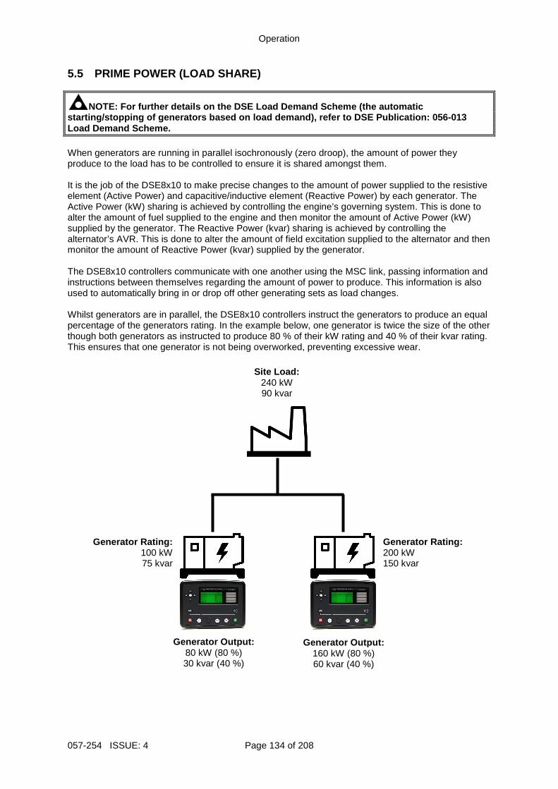
Operation
057-254 ISSUE: 4 Page 134 of 208
5.5 PRIME POWER (LOAD SHARE)
NOTE: For further details on the DSE Load Demand Sc heme (the automatic starting/stopping of generators based on load deman d), refer to DSE Publication: 056-013 Load Demand Scheme. When generators are running in parallel isochronously (zero droop), the amount of power they produce to the load has to be controlled to ensure it is shared amongst them. It is the job of the DSE8x10 to make precise changes to the amount of power supplied to the resistive element (Active Power) and capacitive/inductive element (Reactive Power) by each generator. The Active Power (kW) sharing is achieved by controlling the engine’s governing system. This is done to alter the amount of fuel supplied to the engine and then monitor the amount of Active Power (kW) supplied by the generator. The Reactive Power (kvar) sharing is achieved by controlling the alternator’s AVR. This is done to alter the amount of field excitation supplied to the alternator and then monitor the amount of Reactive Power (kvar) supplied by the generator. The DSE8x10 controllers communicate with one another using the MSC link, passing information and instructions between themselves regarding the amount of power to produce. This information is also used to automatically bring in or drop off other generating sets as load changes. Whilst generators are in parallel, the DSE8x10 controllers instruct the generators to produce an equal percentage of the generators rating. In the example below, one generator is twice the size of the other though both generators as instructed to produce 80 % of their kW rating and 40 % of their kvar rating. This ensures that one generator is not being overworked, preventing excessive wear.
Site Load: 240 kW 90 kvar
Generator Rating: 100 kW 75 kvar
Generator Rating: 200 kW 150 kvar
Generator Output: 80 kW (80 %) 30 kvar (40 %)
Generator Output: 160 kW (80 %) 60 kvar (40 %)
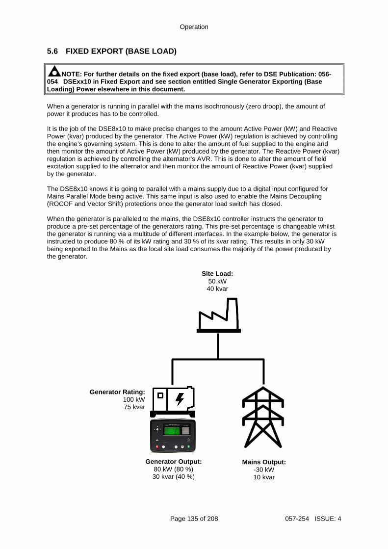
Operation
Page 135 of 208 057-254 ISSUE: 4
5.6 FIXED EXPORT (BASE LOAD)
NOTE: For further details on the fixed export (base load), refer to DSE Publication: 056-054 DSExx10 in Fixed Export and see section entitled Single Generator Exporting (Base Loading) Power elsewhere in this document. When a generator is running in parallel with the mains isochronously (zero droop), the amount of power it produces has to be controlled. It is the job of the DSE8x10 to make precise changes to the amount Active Power (kW) and Reactive Power (kvar) produced by the generator. The Active Power (kW) regulation is achieved by controlling the engine’s governing system. This is done to alter the amount of fuel supplied to the engine and then monitor the amount of Active Power (kW) produced by the generator. The Reactive Power (kvar) regulation is achieved by controlling the alternator’s AVR. This is done to alter the amount of field excitation supplied to the alternator and then monitor the amount of Reactive Power (kvar) supplied by the generator. The DSE8x10 knows it is going to parallel with a mains supply due to a digital input configured for Mains Parallel Mode being active. This same input is also used to enable the Mains Decoupling (ROCOF and Vector Shift) protections once the generator load switch has closed. When the generator is paralleled to the mains, the DSE8x10 controller instructs the generator to produce a pre-set percentage of the generators rating. This pre-set percentage is changeable whilst the generator is running via a multitude of different interfaces. In the example below, the generator is instructed to produce 80 % of its kW rating and 30 % of its kvar rating. This results in only 30 kW being exported to the Mains as the local site load consumes the majority of the power produced by the generator.
Site Load: 50 kW 40 kvar
Generator Rating: 100 kW 75 kvar
Generator Output: 80 kW (80 %) 30 kvar (40 %)
Mains Output: -30 kW 10 kvar
Operation
057-254 ISSUE: 4 Page 136 of 208
5.6.1 POWER MODES
NOTE: The Frequency and Active Power Control modes and Voltage and Reactive Power Control modes are to be used in conjunction with the follow ing documents: - COMMISSION REGULATION (EU) 2016/631 of 14 April 2 016 establishing a network code on requirements for grid connection of generators - P1547 - IEEE Draft Standard for Interconnection a nd Interoperability of Distributed Energy Resources with Associated Electric Power Systems In terfaces
NOTE: For further details of the configuration for the different power modes, refer to DSE Publication: 057-243 DSE8610 MKII Configuration Suite PC Softw are Manual. It is sometimes required that when a generator is placed in parallel with the mains, that it does not simply produced a fixed amount of Active Power (kW) or Reactive Power (kvar). It may be required that the generator automatically varies the amount of Active Power (kW) or Reactive Power (kvar) to stabilise the localised Mains voltage and frequency. For these requirements, the DSE modules have the option to change the mode of operation whilst in parallel with the Mains. 5.6.1.1 FREQUENCY AND ACTIVE (KW) POWER MODES Constant Active Power Mode (Default) This is the default mode of exporting power to the mains (utility); where the DSE load share controller holds the amount of active power produced at a constant level. The amount of active power produced by the generator is irrespective of the load level or any other parameter. The amount of power produced is defined as Maximum kW Level and is set using either the DSE Configuration Suite PC Software, Front Panel Running Editor, in PLC Functions, or via Modbus messages. Frequency - Active Power Mode In this mode of exporting power to the mains (utility); the DSE load share controller varies the amount of active power produced with regards to the Control Curve depending on the measured mains (utility) frequency. This mode allows the generator to support the mains (utility) frequency stability by monitoring the frequency and changing the amount of active power produced. Voltage – Active Power Mode In this mode of exporting power to the mains (utility); the DSE load share controller varies the amount of active power produced with regards to the Control Curve depending on the measured mains (utility) voltage. This mode allows the generator to support the mains (utility) voltage stability by monitoring the voltage and changing the amount of active power produced.
Operation
Page 137 of 208 057-254 ISSUE: 4
5.6.1.2 VOLTAGE AND REACTIVE (KVAR) POWER CONTROL Constant Reactive Power Mode (Default) This is the default mode of exporting power to the mains (utility); where the DSE load share controller holds the amount of reactive power produced at a constant level. The amount of reactive power produced by the generator is irrespective of the load level or any other parameter. The amount of reactive power produced is defined as Maximum kVAr Level and is set using either the DSE Configuration Suite PC Software, Front Panel Running Editor, in PLC Functions, or via Modbus messages. The user has the option to limit the amount of reactive power the generator produces to within their power factor depending on the amount of active power produced. Regardless of this option, the generator does not produce more than its rated reactive power. Constant Power Factor Mode In this mode of exporting power to the mains (utility); the DSE load share controller varies the amount of reactive power produced with regards to maintaining the required power factor. This mode allows the generator to maintain a constant export power factor if so required. The required power factor is set using either the DSE Configuration Suite PC Software, Front Panel Running Editor, in PLC Functions, or via Modbus messages. Voltage - Reactive Power Mode In this mode of exporting power to the mains (utility); the DSE load share controller varies the amount of reactive power produced with regards to the Control Curve depending on the measured voltage. This mode allows the generator to support the mains (utility) voltage stability by monitoring the voltage and changing the amount of reactive power produced. Power - Power Factor Mode In this mode of exporting power to the mains (utility); the DSE load share controller varies the amount of reactive power produced with regards to maintaining the required power factor. This power factor is derived from the averaged power using the Control Curve. This mode allows the generator to support the mains (utility) stability by varying the power factor depending on the produced active power.
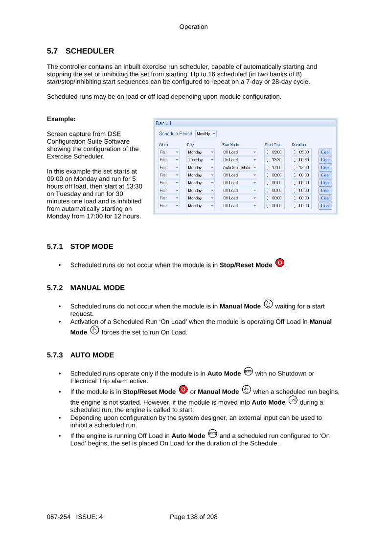
Operation
057-254 ISSUE: 4 Page 138 of 208
5.7 SCHEDULER The controller contains an inbuilt exercise run scheduler, capable of automatically starting and stopping the set or inhibiting the set from starting. Up to 16 scheduled (in two banks of 8) start/stop/inhibiting start sequences can be configured to repeat on a 7-day or 28-day cycle. Scheduled runs may be on load or off load depending upon module configuration. Example: Screen capture from DSE Configuration Suite Software showing the configuration of the Exercise Scheduler. In this example the set starts at 09:00 on Monday and run for 5 hours off load, then start at 13:30 on Tuesday and run for 30 minutes one load and is inhibited from automatically starting on Monday from 17:00 for 12 hours. 5.7.1 STOP MODE
• Scheduled runs do not occur when the module is in Stop/Reset Mode . 5.7.2 MANUAL MODE
• Scheduled runs do not occur when the module is in Manual Mode waiting for a start request.
• Activation of a Scheduled Run ‘On Load’ when the module is operating Off Load in Manual
Mode forces the set to run On Load. 5.7.3 AUTO MODE
• Scheduled runs operate only if the module is in Auto Mode with no Shutdown or Electrical Trip alarm active.
• If the module is in Stop/Reset Mode or Manual Mode when a scheduled run begins,
the engine is not started. However, if the module is moved into Auto Mode during a scheduled run, the engine is called to start.
• Depending upon configuration by the system designer, an external input can be used to inhibit a scheduled run.
• If the engine is running Off Load in Auto Mode and a scheduled run configured to ‘On Load’ begins, the set is placed On Load for the duration of the Schedule.
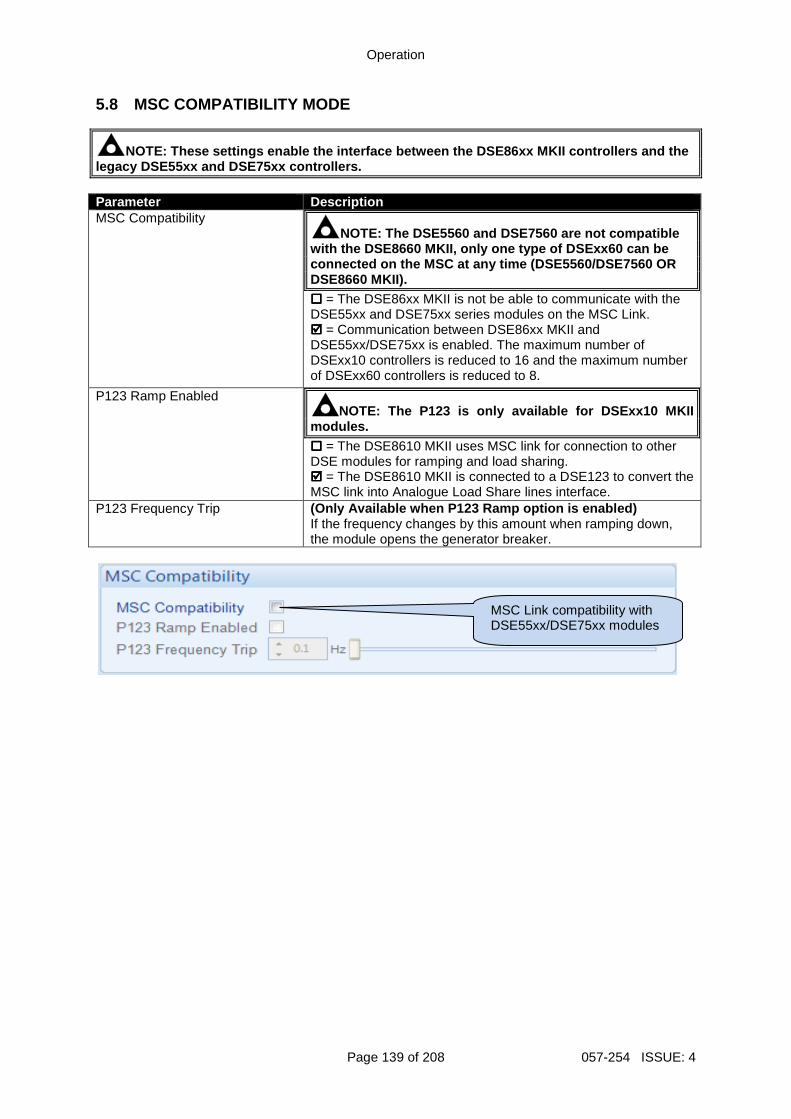
Operation
Page 139 of 208 057-254 ISSUE: 4
5.8 MSC COMPATIBILITY MODE
NOTE: These settings enable the interface between t he DSE86xx MKII controllers and the legacy DSE55xx and DSE75xx controllers. Parameter Description MSC Compatibility
NOTE: The DSE5560 and DSE7560 are not compatible with the DSE8660 MKII, only one type of DSExx60 can be connected on the MSC at any time (DSE5560/DSE7560 O R DSE8660 MKII). = The DSE86xx MKII is not be able to communicate with the DSE55xx and DSE75xx series modules on the MSC Link. = Communication between DSE86xx MKII and DSE55xx/DSE75xx is enabled. The maximum number of DSExx10 controllers is reduced to 16 and the maximum number of DSExx60 controllers is reduced to 8.
P123 Ramp Enabled NOTE: The P123 is only available for DSExx10 MKII
modules. = The DSE8610 MKII uses MSC link for connection to other DSE modules for ramping and load sharing. = The DSE8610 MKII is connected to a DSE123 to convert the MSC link into Analogue Load Share lines interface.
P123 Frequency Trip (Only Available when P123 Ramp option is enabled) If the frequency changes by this amount when ramping down, the module opens the generator breaker.
MSC Link compatibility with DSE55xx/DSE75xx modules
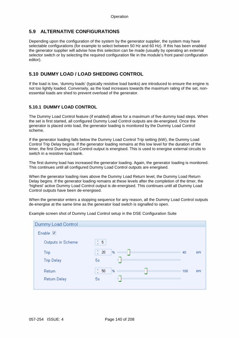
Operation
057-254 ISSUE: 4 Page 140 of 208
5.9 ALTERNATIVE CONFIGURATIONS Depending upon the configuration of the system by the generator supplier, the system may have selectable configurations (for example to select between 50 Hz and 60 Hz). If this has been enabled the generator supplier will advise how this selection can be made (usually by operating an external selector switch or by selecting the required configuration file in the module’s front panel configuration editor). 5.10 DUMMY LOAD / LOAD SHEDDING CONTROL If the load is low, ‘dummy loads’ (typically resistive load banks) are introduced to ensure the engine is not too lightly loaded. Conversely, as the load increases towards the maximum rating of the set, non-essential loads are shed to prevent overload of the generator. 5.10.1 DUMMY LOAD CONTROL The Dummy Load Control feature (if enabled) allows for a maximum of five dummy load steps. When the set is first started, all configured Dummy Load Control outputs are de-energised. Once the generator is placed onto load, the generator loading is monitored by the Dummy Load Control scheme. If the generator loading falls below the Dummy Load Control Trip setting (kW), the Dummy Load Control Trip Delay begins. If the generator loading remains at this low level for the duration of the timer, the first Dummy Load Control output is energised. This is used to energise external circuits to switch in a resistive load bank. The first dummy load has increased the generator loading. Again, the generator loading is monitored. This continues until all configured Dummy Load Control outputs are energised. When the generator loading rises above the Dummy Load Return level, the Dummy Load Return Delay begins. If the generator loading remains at these levels after the completion of the timer, the ‘highest’ active Dummy Load Control output is de-energised. This continues until all Dummy Load Control outputs have been de-energised. When the generator enters a stopping sequence for any reason, all the Dummy Load Control outputs de-energise at the same time as the generator load switch is signalled to open. Example screen shot of Dummy Load Control setup in the DSE Configuration Suite
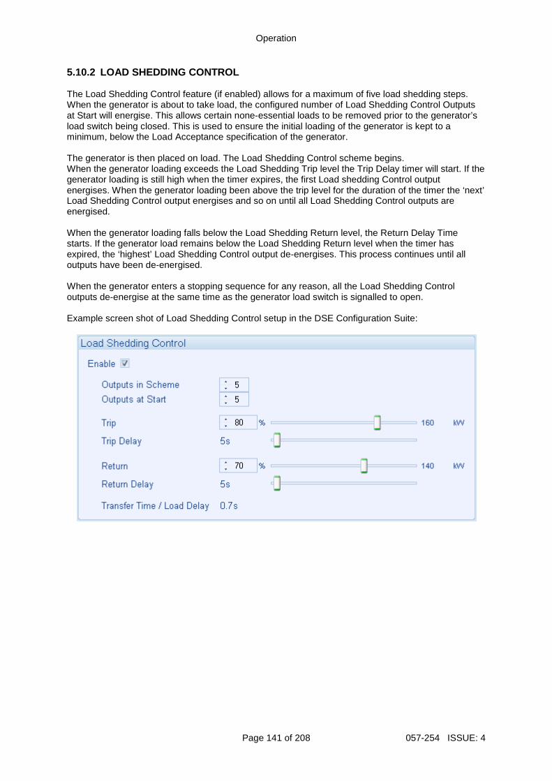
Operation
Page 141 of 208 057-254 ISSUE: 4
5.10.2 LOAD SHEDDING CONTROL The Load Shedding Control feature (if enabled) allows for a maximum of five load shedding steps. When the generator is about to take load, the configured number of Load Shedding Control Outputs at Start will energise. This allows certain none-essential loads to be removed prior to the generator’s load switch being closed. This is used to ensure the initial loading of the generator is kept to a minimum, below the Load Acceptance specification of the generator. The generator is then placed on load. The Load Shedding Control scheme begins. When the generator loading exceeds the Load Shedding Trip level the Trip Delay timer will start. If the generator loading is still high when the timer expires, the first Load shedding Control output energises. When the generator loading been above the trip level for the duration of the timer the ‘next’ Load Shedding Control output energises and so on until all Load Shedding Control outputs are energised. When the generator loading falls below the Load Shedding Return level, the Return Delay Time starts. If the generator load remains below the Load Shedding Return level when the timer has expired, the ‘highest’ Load Shedding Control output de-energises. This process continues until all outputs have been de-energised. When the generator enters a stopping sequence for any reason, all the Load Shedding Control outputs de-energise at the same time as the generator load switch is signalled to open. Example screen shot of Load Shedding Control setup in the DSE Configuration Suite:
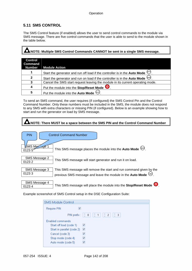
Operation
057-254 ISSUE: 4 Page 142 of 208
5.11 SMS CONTROL The SMS Control feature (if enabled) allows the user to send control commands to the module via SMS message. There are five control commands that the user is able to send to the module shown in the table below.
NOTE: Multiple SMS Control Commands CANNOT be sent in a single SMS message.
Control Command Number Module Action
1 Start the generator and run off load if the controller is in the Auto Mode . 2 Start the generator and run on load if the controller is in the Auto Mode . 3 Cancel the SMS start request leaving the module in its current operating mode. 4 Put the module into the Stop/Reset Mode . 5 Put the module into the Auto Mode .
To send an SMS command, the user requires (if configured) the SMS Control Pin and the Control Command Number. Only these numbers must be included in the SMS, the module does not respond to any SMS with extra characters or missing PIN (if configured). Below is an example showing how to start and run the generator on load by SMS message.
NOTE: There MUST be a space between the SMS PIN and the Control Command Number
SMS Message 1 This SMS message places the module into the Auto Mode . 0123 5
SMS Message 2
This SMS message will start generator and run it on load. 0123 2
SMS Message 3 This SMS message will remove the start and run command given by the
previous SMS message and leave the module in the Auto Mode . 0123 3
SMS Message 4
This SMS message will place the module into the Stop/Reset Mode . 0123 4 Example screenshot of SMS Control setup in the DSE Configuration Suite:
PIN
Control Command Number
Operation
Page 143 of 208 057-254 ISSUE: 4
5.12 DEAD BUS SYNCHRONISING (AUTO MODE)
NOTE: For further details on Dead Bus Synchronising , refer to DSE Publication: 056-072 Dead Bus Synchronising Training Document. 5.12.1 BENEFIT OF SYSTEM Generator set specifications often contain the requirement for the set to be on load within 15 seconds of a mains supply failure. This is easily achievable in single set applications. However in the current era of fuel conservation, multiple sets are often used to provide the backup power solution for many applications. This gives challenges in starting and synchronising the required sets before they can be used to power the load. The solution to this is a longstanding one, having being used for many decades. However modern digital communications such as the DSE MSC link has vastly improved the control and hence safety of the system operation. The solution is called Dead Bus Synchronising. Using Dead Bus Synchronising, any number of generators are able to be online and in parallel potentially within 15 seconds, depending upon applications and hardware used. 5.12.2 HARDWARE REQUIREMENTS
• DSE8610 MKII controller. • DC controlled generator load switch. • Auxiliary contact to feed back generator breaker status to the DSE controller. • External relay driven by the DSE module to isolate the supply to the AVR inside the
generator’s alternator. • Speed detection using an MPU or CAN signal.
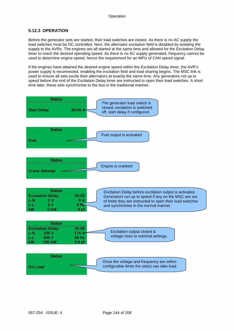
Operation
057-254 ISSUE: 4 Page 144 of 208
5.12.3 OPERATION Before the generator sets are started, their load switches are closed. As there is no AC supply the load switches must be DC controlled. Next, the alternator excitation field is disabled by isolating the supply to the AVRs. The engines are all started at the same time and allowed for the Excitation Delay timer to reach the desired operating speed. As there is no AC supply generated, frequency cannot be used to determine engine speed, hence the requirement for an MPU of CAN speed signal. If the engines have attained the desired engine speed within the Excitation Delay timer, the AVR’s power supply is reconnected, enabling the excitation field and load sharing begins. The MSC link is used to ensure all sets excite their alternators at exactly the same time. Any generators not up to speed before the end of the Excitation Delay timer are instructed to open their load switches. A short time later, these sets synchronise to the bus in the traditional manner.
Status
Start Delay 00:00 s
Status
Fuel
Status
Crank Attempt
Status Excitation Delay L-N 0 V L-L 0 V kW 0 kW
00:03 0 A
0 Hz 0 pf
Status Excitation Delay L-N 230 V L-L 400 V kW 100 kW
00:00 174 A 50 Hz 0.8 pf
Status
On Load
Excitation output closed & voltage rises to nominal settings.
Once the voltage and frequency are within configurable limits the set(s) can take load.
The generator load switch is closed, excitation is switched off, start delay if configured.
Fuel output is activated
Engine is cranked
Excitation Delay before excitation output is activated. Generators run up to speed if any on the MSC are out of limits they are instructed to open their load switches and synchronise in the normal manner.
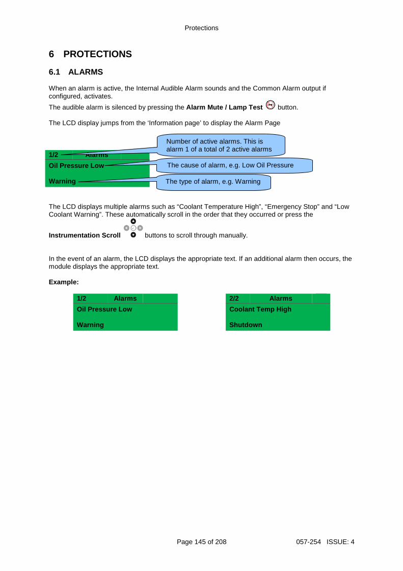
Protections
Page 145 of 208 057-254 ISSUE: 4
6 PROTECTIONS 6.1 ALARMS When an alarm is active, the Internal Audible Alarm sounds and the Common Alarm output if configured, activates.
The audible alarm is silenced by pressing the Alarm Mute / Lamp Test button. The LCD display jumps from the ‘Information page’ to display the Alarm Page 1/2 Alarms
Oil Pressure Low Warning The LCD displays multiple alarms such as “Coolant Temperature High”, “Emergency Stop” and “Low Coolant Warning”. These automatically scroll in the order that they occurred or press the
Instrumentation Scroll buttons to scroll through manually. In the event of an alarm, the LCD displays the appropriate text. If an additional alarm then occurs, the module displays the appropriate text. Example:
1/2 Alarms 2/2 Alarms
Oil Pressure Low Warning
Coolant Temp High Shutdown
The type of alarm, e.g. Warning
The cause of alarm, e.g. Low Oil Pressure
Number of active alarms. This is alarm 1 of a total of 2 active alarms
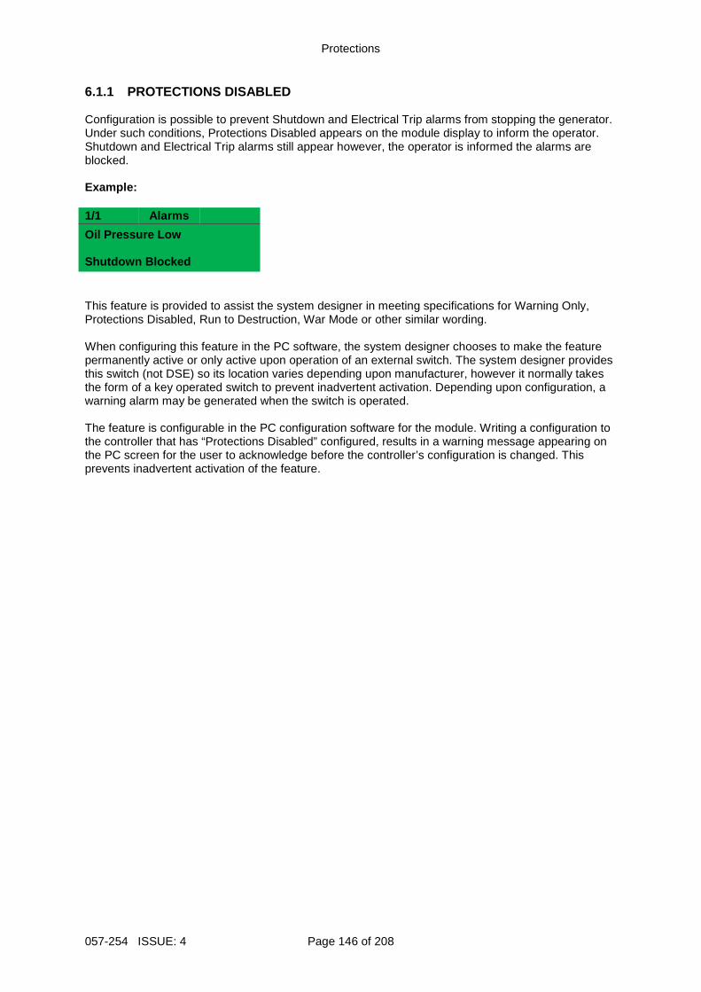
Protections
057-254 ISSUE: 4 Page 146 of 208
6.1.1 PROTECTIONS DISABLED Configuration is possible to prevent Shutdown and Electrical Trip alarms from stopping the generator. Under such conditions, Protections Disabled appears on the module display to inform the operator. Shutdown and Electrical Trip alarms still appear however, the operator is informed the alarms are blocked. Example: 1/1 Alarms
Oil Pressure Low Shutdown Blocked This feature is provided to assist the system designer in meeting specifications for Warning Only, Protections Disabled, Run to Destruction, War Mode or other similar wording. When configuring this feature in the PC software, the system designer chooses to make the feature permanently active or only active upon operation of an external switch. The system designer provides this switch (not DSE) so its location varies depending upon manufacturer, however it normally takes the form of a key operated switch to prevent inadvertent activation. Depending upon configuration, a warning alarm may be generated when the switch is operated. The feature is configurable in the PC configuration software for the module. Writing a configuration to the controller that has “Protections Disabled” configured, results in a warning message appearing on the PC screen for the user to acknowledge before the controller’s configuration is changed. This prevents inadvertent activation of the feature.
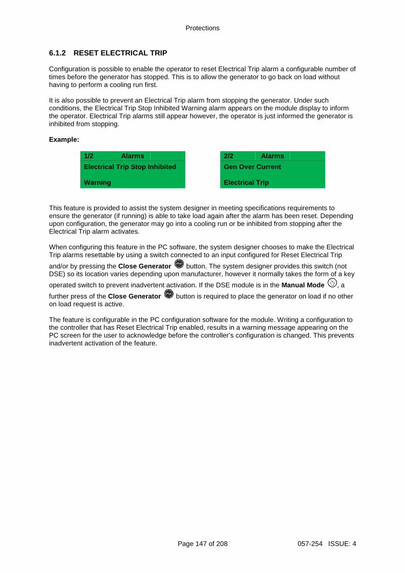
Protections
Page 147 of 208 057-254 ISSUE: 4
6.1.2 RESET ELECTRICAL TRIP Configuration is possible to enable the operator to reset Electrical Trip alarm a configurable number of times before the generator has stopped. This is to allow the generator to go back on load without having to perform a cooling run first. It is also possible to prevent an Electrical Trip alarm from stopping the generator. Under such conditions, the Electrical Trip Stop Inhibited Warning alarm appears on the module display to inform the operator. Electrical Trip alarms still appear however, the operator is just informed the generator is inhibited from stopping. Example:
1/2 Alarms 2/2 Alarms
Electrical Trip Stop Inhibited Warning
Gen Over Current Electrical Trip
This feature is provided to assist the system designer in meeting specifications requirements to ensure the generator (if running) is able to take load again after the alarm has been reset. Depending upon configuration, the generator may go into a cooling run or be inhibited from stopping after the Electrical Trip alarm activates. When configuring this feature in the PC software, the system designer chooses to make the Electrical Trip alarms resettable by using a switch connected to an input configured for Reset Electrical Trip
and/or by pressing the Close Generator button. The system designer provides this switch (not DSE) so its location varies depending upon manufacturer, however it normally takes the form of a key
operated switch to prevent inadvertent activation. If the DSE module is in the Manual Mode , a
further press of the Close Generator button is required to place the generator on load if no other on load request is active. The feature is configurable in the PC configuration software for the module. Writing a configuration to the controller that has Reset Electrical Trip enabled, results in a warning message appearing on the PC screen for the user to acknowledge before the controller’s configuration is changed. This prevents inadvertent activation of the feature.
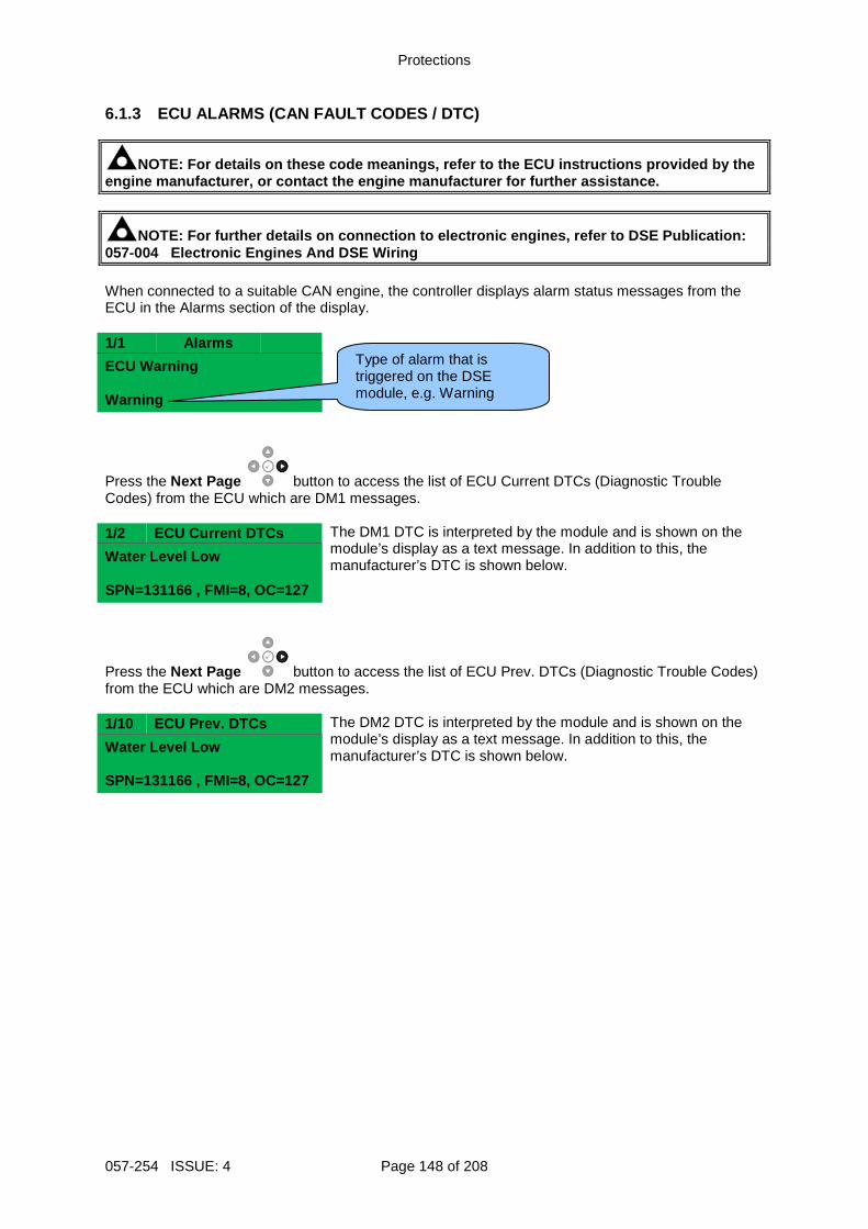
Protections
057-254 ISSUE: 4 Page 148 of 208
6.1.3 ECU ALARMS (CAN FAULT CODES / DTC)
NOTE: For details on these code meanings, refer to the ECU instructions provided by the engine manufacturer, or contact the engine manufact urer for further assistance.
NOTE: For further details on connection to electron ic engines, refer to DSE Publication: 057-004 Electronic Engines And DSE Wiring When connected to a suitable CAN engine, the controller displays alarm status messages from the ECU in the Alarms section of the display. 1/1 Alarms
ECU Warning Warning
Press the Next Page button to access the list of ECU Current DTCs (Diagnostic Trouble Codes) from the ECU which are DM1 messages. 1/2 ECU Current DTCs The DM1 DTC is interpreted by the module and is shown on the
module’s display as a text message. In addition to this, the manufacturer’s DTC is shown below.
Water Level Low SPN=131166 , FMI=8, OC=127
Press the Next Page button to access the list of ECU Prev. DTCs (Diagnostic Trouble Codes) from the ECU which are DM2 messages. 1/10 ECU Prev. DTCs The DM2 DTC is interpreted by the module and is shown on the
module’s display as a text message. In addition to this, the manufacturer’s DTC is shown below.
Water Level Low SPN=131166 , FMI=8, OC=127
Type of alarm that is triggered on the DSE module, e.g. Warning
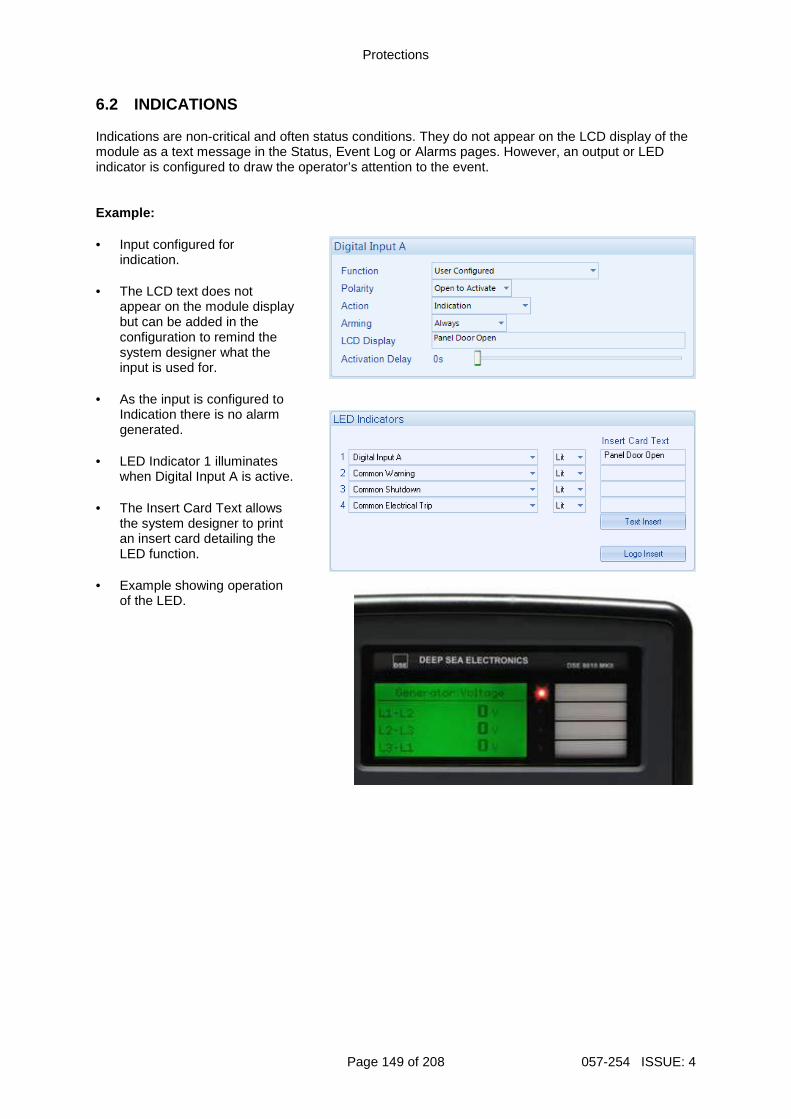
Protections
Page 149 of 208 057-254 ISSUE: 4
6.2 INDICATIONS Indications are non-critical and often status conditions. They do not appear on the LCD display of the module as a text message in the Status, Event Log or Alarms pages. However, an output or LED indicator is configured to draw the operator’s attention to the event. Example: • Input configured for
indication. • The LCD text does not
appear on the module display but can be added in the configuration to remind the system designer what the input is used for.
• As the input is configured to
Indication there is no alarm generated.
• LED Indicator 1 illuminates
when Digital Input A is active.
• The Insert Card Text allows the system designer to print an insert card detailing the LED function.
• Example showing operation of the LED.
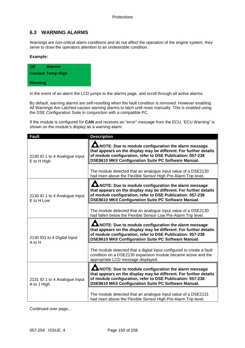
Protections
057-254 ISSUE: 4 Page 150 of 208
6.3 WARNING ALARMS Warnings are non-critical alarm conditions and do not affect the operation of the engine system, they serve to draw the operators attention to an undesirable condition. Example: 1/2 Alarms
Coolant Temp High Warning In the event of an alarm the LCD jumps to the alarms page, and scroll through all active alarms. By default, warning alarms are self-resetting when the fault condition is removed. However enabling All Warnings Are Latched causes warning alarms to latch until reset manually. This is enabled using the DSE Configuration Suite in conjunction with a compatible PC. If the module is configured for CAN and receives an “error” message from the ECU, ‘ECU Warning” is shown on the module’s display as a warning alarm. Fault Description
2130 ID 1 to 4 Analogue Input E to H High
NOTE: Due to module configuration the alarm message that appears on the display may be different. For f urther details of module configuration, refer to DSE Publication: 057-238 DSE8610 MKII Configuration Suite PC Software Manual . The module detected that an analogue input value of a DSE2130 had risen above the Flexible Sensor High Pre-Alarm Trip level.
2130 ID 1 to 4 Analogue Input E to H Low
NOTE: Due to module configuration the alarm message that appears on the display may be different. For f urther details of module configuration, refer to DSE Publication: 057-238 DSE8610 MKII Configuration Suite PC Software Manual . The module detected that an analogue input value of a DSE2130 had fallen below the Flexible Sensor Low Pre-Alarm Trip level.
2130 ID1 to 4 Digital Input A to H
NOTE: Due to module configuration the alarm message that appears on the display may be different. For f urther details of module configuration, refer to DSE Publication: 057-238 DSE8610 MKII Configuration Suite PC Software Manual . The module detected that a digital input configured to create a fault condition on a DSE2130 expansion module became active and the appropriate LCD message displayed.
2131 ID 1 to 4 Analogue Input A to J High
NOTE: Due to module configuration the alarm message that appears on the display may be different. For f urther details of module configuration, refer to DSE Publication: 057-238 DSE8610 MKII Configuration Suite PC Software Manual . The module detected that an analogue input value of a DSE2131 had risen above the Flexible Sensor High Pre-Alarm Trip level.
Continued over page…
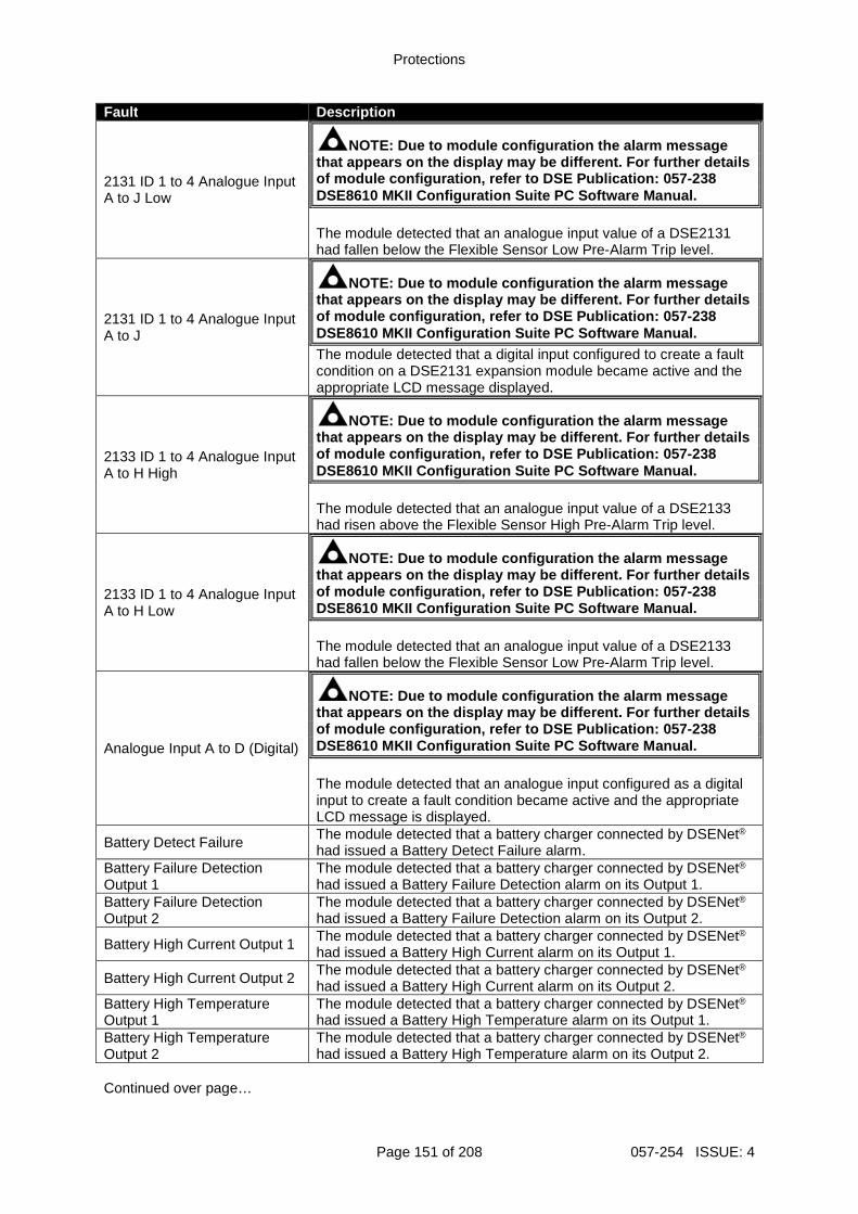
Protections
Page 151 of 208 057-254 ISSUE: 4
Fault Description
2131 ID 1 to 4 Analogue Input A to J Low
NOTE: Due to module configuration the alarm message that appears on the display may be different. For f urther details of module configuration, refer to DSE Publication: 057-238 DSE8610 MKII Configuration Suite PC Software Manual . The module detected that an analogue input value of a DSE2131 had fallen below the Flexible Sensor Low Pre-Alarm Trip level.
2131 ID 1 to 4 Analogue Input A to J
NOTE: Due to module configuration the alarm message that appears on the display may be different. For f urther details of module configuration, refer to DSE Publication: 057-238 DSE8610 MKII Configuration Suite PC Software Manual . The module detected that a digital input configured to create a fault condition on a DSE2131 expansion module became active and the appropriate LCD message displayed.
2133 ID 1 to 4 Analogue Input A to H High
NOTE: Due to module configuration the alarm message that appears on the display may be different. For f urther details of module configuration, refer to DSE Publication: 057-238 DSE8610 MKII Configuration Suite PC Software Manual . The module detected that an analogue input value of a DSE2133 had risen above the Flexible Sensor High Pre-Alarm Trip level.
2133 ID 1 to 4 Analogue Input A to H Low
NOTE: Due to module configuration the alarm message that appears on the display may be different. For f urther details of module configuration, refer to DSE Publication: 057-238 DSE8610 MKII Configuration Suite PC Software Manual . The module detected that an analogue input value of a DSE2133 had fallen below the Flexible Sensor Low Pre-Alarm Trip level.
Analogue Input A to D (Digital)
NOTE: Due to module configuration the alarm message that appears on the display may be different. For f urther details of module configuration, refer to DSE Publication: 057-238 DSE8610 MKII Configuration Suite PC Software Manual . The module detected that an analogue input configured as a digital input to create a fault condition became active and the appropriate LCD message is displayed.
Battery Detect Failure The module detected that a battery charger connected by DSENet®
had issued a Battery Detect Failure alarm. Battery Failure Detection Output 1
The module detected that a battery charger connected by DSENet®
had issued a Battery Failure Detection alarm on its Output 1. Battery Failure Detection Output 2
The module detected that a battery charger connected by DSENet®
had issued a Battery Failure Detection alarm on its Output 2.
Battery High Current Output 1 The module detected that a battery charger connected by DSENet®
had issued a Battery High Current alarm on its Output 1.
Battery High Current Output 2 The module detected that a battery charger connected by DSENet®
had issued a Battery High Current alarm on its Output 2. Battery High Temperature Output 1
The module detected that a battery charger connected by DSENet®
had issued a Battery High Temperature alarm on its Output 1. Battery High Temperature Output 2
The module detected that a battery charger connected by DSENet®
had issued a Battery High Temperature alarm on its Output 2. Continued over page…
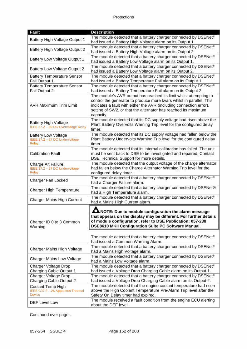
Protections
057-254 ISSUE: 4 Page 152 of 208
Fault Description
Battery High Voltage Output 1 The module detected that a battery charger connected by DSENet®
had issued a Battery High Voltage alarm on its Output 1.
Battery High Voltage Output 2 The module detected that a battery charger connected by DSENet®
had issued a Battery High Voltage alarm on its Output 2.
Battery Low Voltage Output 1 The module detected that a battery charger connected by DSENet®
had issued a Battery Low Voltage alarm on its Output 1.
Battery Low Voltage Output 2 The module detected that a battery charger connected by DSENet®
had issued a Battery Low Voltage alarm on its Output 2. Battery Temperature Sensor Fail Output 1
The module detected that a battery charger connected by DSENet®
had issued a Battery Temperature Fail alarm on its Output 1. Battery Temperature Sensor Fail Output 2
The module detected that a battery charger connected by DSENet®
had issued a Battery Temperature Fail alarm on its Output 2.
AVR Maximum Trim Limit
The module’s AVR output has reached its limit whilst attempting to control the generator to produce more kvars whilst in parallel. This indicates a fault with either the AVR (including connection error), setting of SW2, or that the alternator has reached its maximum capacity.
Battery High Voltage IEEE 37.2 – 59 DC Overvoltage Relay
The module detected that its DC supply voltage had risen above the Plant Battery Overvolts Warning Trip level for the configured delay timer.
Battery Low Voltage IEEE 37.2 – 27 DC Undervoltage Relay
The module detected that its DC supply voltage had fallen below the Plant Battery Undervolts Warning Trip level for the configured delay timer.
Calibration Fault The module detected that its internal calibration has failed. The unit must be sent back to DSE to be investigated and repaired. Contact DSE Technical Support for more details.
Charge Alt Failure IEEE 37.2 – 27 DC Undervoltage Relay
The module detected that the output voltage of the charge alternator had fallen below the Charge Alternator Warning Trip level for the configured delay timer.
Charger Fan Locked The module detected that a battery charger connected by DSENet®
had a Charger Failure alarm.
Charger High Temperature The module detected that a battery charger connected by DSENet® had a High Temperature alarm.
Charger Mains High Current The module detected that a battery charger connected by DSENet®
had a Mains High Current alarm.
Charger ID 0 to 3 Common Warning
NOTE: Due to module configuration the alarm message that appears on the display may be different. For f urther details of module configuration, refer to DSE Publication: 057-238 DSE8610 MKII Configuration Suite PC Software Manual . The module detected that a battery charger connected by DSENet®
had issued a Common Warning Alarm.
Charger Mains High Voltage The module detected that a battery charger connected by DSENet®
had a Mains High Voltage alarm.
Charger Mains Low Voltage The module detected that a battery charger connected by DSENet®
had a Mains Low Voltage alarm. Charger Voltage Drop Charging Cable Output 1
The module detected that a battery charger connected by DSENet®
had issued a Voltage Drop Charging Cable alarm on its Output 1. Charger Voltage Drop Charging Cable Output 2
The module detected that a battery charger connected by DSENet®
had issued a Voltage Drop Charging Cable alarm on its Output 2.
Coolant Temp High IEEE C37.2 – 26 Apparatus Thermal Device
The module detected that the engine coolant temperature had risen above the High Coolant Temperature Pre-Alarm Trip level after the Safety On Delay timer had expired.
DEF Level Low The module received a fault condition from the engine ECU alerting about the DEF level.
Continued over page…
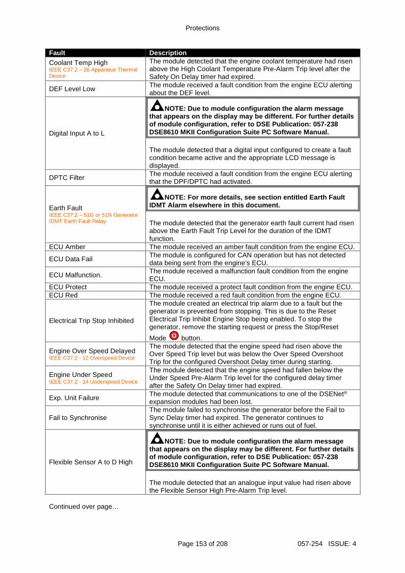
Protections
Page 153 of 208 057-254 ISSUE: 4
Fault Description Coolant Temp High IEEE C37.2 – 26 Apparatus Thermal Device
The module detected that the engine coolant temperature had risen above the High Coolant Temperature Pre-Alarm Trip level after the Safety On Delay timer had expired.
DEF Level Low The module received a fault condition from the engine ECU alerting about the DEF level.
Digital Input A to L
NOTE: Due to module configuration the alarm message that appears on the display may be different. For f urther details of module configuration, refer to DSE Publication: 057-238 DSE8610 MKII Configuration Suite PC Software Manual . The module detected that a digital input configured to create a fault condition became active and the appropriate LCD message is displayed.
DPTC Filter The module received a fault condition from the engine ECU alerting that the DPF/DPTC had activated.
Earth Fault IEEE C37.2 – 51G or 51N Generator IDMT Earth Fault Relay
NOTE: For more details, see section entitled Earth Fault IDMT Alarm elsewhere in this document. The module detected that the generator earth fault current had risen above the Earth Fault Trip Level for the duration of the IDMT function.
ECU Amber The module received an amber fault condition from the engine ECU.
ECU Data Fail The module is configured for CAN operation but has not detected data being sent from the engine’s ECU.
ECU Malfunction. The module received a malfunction fault condition from the engine ECU.
ECU Protect The module received a protect fault condition from the engine ECU. ECU Red The module received a red fault condition from the engine ECU.
Electrical Trip Stop Inhibited
The module created an electrical trip alarm due to a fault but the generator is prevented from stopping. This is due to the Reset Electrical Trip Inhibit Engine Stop being enabled. To stop the generator, remove the starting request or press the Stop/Reset
Mode button.
Engine Over Speed Delayed IEEE C37.2 - 12 Overspeed Device
The module detected that the engine speed had risen above the Over Speed Trip level but was below the Over Speed Overshoot Trip for the configured Overshoot Delay timer during starting.
Engine Under Speed IEEE C37.2 - 14 Underspeed Device
The module detected that the engine speed had fallen below the Under Speed Pre-Alarm Trip level for the configured delay timer after the Safety On Delay timer had expired.
Exp. Unit Failure The module detected that communications to one of the DSENet® expansion modules had been lost.
Fail to Synchronise The module failed to synchronise the generator before the Fail to Sync Delay timer had expired. The generator continues to synchronise until it is either achieved or runs out of fuel.
Flexible Sensor A to D High
NOTE: Due to module configuration the alarm message that appears on the display may be different. For f urther details of module configuration, refer to DSE Publication: 057-238 DSE8610 MKII Configuration Suite PC Software Manual . The module detected that an analogue input value had risen above the Flexible Sensor High Pre-Alarm Trip level.
Continued over page…
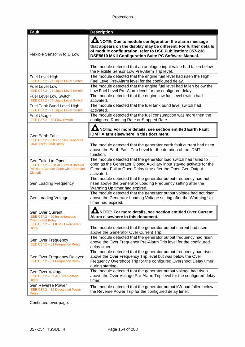
Protections
057-254 ISSUE: 4 Page 154 of 208
Fault Description
Flexible Sensor A to D Low
NOTE: Due to module configuration the alarm message that appears on the display may be different. For f urther details of module configuration, refer to DSE Publication: 057-238 DSE8610 MKII Configuration Suite PC Software Manual . The module detected that an analogue input value had fallen below the Flexible Sensor Low Pre-Alarm Trip level.
Fuel Level High IEEE C37.2 - 71 Liquid Level Switch
The module detected that the engine fuel level had risen the High Fuel Level Pre-Alarm level for the configured delay.
Fuel Level Low IEEE C37.2 - 71 Liquid Level Switch
The module detected that the engine fuel level had fallen below the Low Fuel Level Pre-Alarm level for the configured delay
Fuel Level Low Switch IEEE C37.2 - 71 Liquid Level Switch
The module detected that the engine low fuel level switch had activated.
Fuel Tank Bund Level High IEEE C37.2 - 71 Liquid Level Switch
The module detected that the fuel tank bund level switch had activated.
Fuel Usage IEEE C37.2 – 80 Flow Switch
The module detected that the fuel consumption was more then the configured Running Rate or Stopped Rate.
Gen Earth Fault IEEE C37.2 – 51G or 51N Generator IDMT Earth Fault Relay
NOTE: For more details, see section entitled Earth Fault IDMT Alarm elsewhere in this document. The module detected that the generator earth fault current had risen above the Earth Fault Trip Level for the duration of the IDMT function.
Gen Failed to Open IEEE C37.2 – 52b AC Circuit Breaker Position (Contact Open when Breaker Closed)
The module detected that the generator load switch had failed to open as the Generator Closed Auxiliary input stayed activate for the Generator Fail to Open Delay time after the Open Gen Output activated.
Gen Loading Frequency The module detected that the generator output frequency had not risen above the Generator Loading Frequency setting after the Warming Up timer had expired.
Gen Loading Voltage The module detected that the generator output voltage had not risen above the Generator Loading Voltage setting after the Warming Up timer had expired.
Gen Over Current IEEE C37.2 – 50 Instantaneous Overcurrent Relay IEEE C37.2 – 51 IDMT Overcurrent Relay
NOTE: For more details, see section entitled Over Current Alarm elsewhere in this document. The module detected that the generator output current had risen above the Generator Over Current Trip.
Gen Over Frequency IEEE C37.2 – 81 Frequency Relay
The module detected that the generator output frequency had risen above the Over Frequency Pre-Alarm Trip level for the configured delay timer.
Gen Over Frequency Delayed IEEE C37.2 – 81 Frequency Relay
The module detected that the generator output frequency had risen above the Over Frequency Trip level but was below the Over Frequency Overshoot Trip for the configured Overshoot Delay timer during starting.
Gen Over Voltage IEEE C37.2 – 59 AC Overvoltage Relay
The module detected that the generator output voltage had risen above the Over Voltage Pre-Alarm Trip level for the configured delay timer.
Gen Reverse Power IEEE C37.2 – 32 Directional Power Relay
The module detected that the generator output kW had fallen below the Reverse Power Trip for the configured delay timer.
Continued over page…
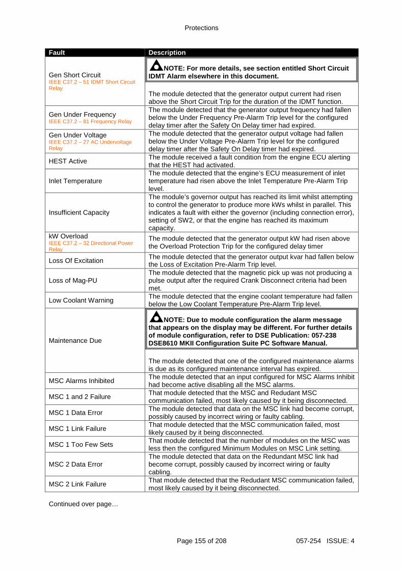
Protections
Page 155 of 208 057-254 ISSUE: 4
Fault Description
Gen Short Circuit IEEE C37.2 – 51 IDMT Short Circuit Relay
NOTE: For more details, see section entitled Short Circuit IDMT Alarm elsewhere in this document. The module detected that the generator output current had risen above the Short Circuit Trip for the duration of the IDMT function.
Gen Under Frequency IEEE C37.2 – 81 Frequency Relay
The module detected that the generator output frequency had fallen below the Under Frequency Pre-Alarm Trip level for the configured delay timer after the Safety On Delay timer had expired.
Gen Under Voltage IEEE C37.2 – 27 AC Undervoltage Relay
The module detected that the generator output voltage had fallen below the Under Voltage Pre-Alarm Trip level for the configured delay timer after the Safety On Delay timer had expired.
HEST Active The module received a fault condition from the engine ECU alerting that the HEST had activated.
Inlet Temperature The module detected that the engine’s ECU measurement of inlet temperature had risen above the Inlet Temperature Pre-Alarm Trip level.
Insufficient Capacity
The module’s governor output has reached its limit whilst attempting to control the generator to produce more kWs whilst in parallel. This indicates a fault with either the governor (including connection error), setting of SW2, or that the engine has reached its maximum capacity.
kW Overload IEEE C37.2 – 32 Directional Power Relay
The module detected that the generator output kW had risen above the Overload Protection Trip for the configured delay timer
Loss Of Excitation The module detected that the generator output kvar had fallen below the Loss of Excitation Pre-Alarm Trip level.
Loss of Mag-PU The module detected that the magnetic pick up was not producing a pulse output after the required Crank Disconnect criteria had been met.
Low Coolant Warning The module detected that the engine coolant temperature had fallen below the Low Coolant Temperature Pre-Alarm Trip level.
Maintenance Due
NOTE: Due to module configuration the alarm message that appears on the display may be different. For f urther details of module configuration, refer to DSE Publication: 057-238 DSE8610 MKII Configuration Suite PC Software Manual . The module detected that one of the configured maintenance alarms is due as its configured maintenance interval has expired.
MSC Alarms Inhibited The module detected that an input configured for MSC Alarms Inhibit had become active disabling all the MSC alarms.
MSC 1 and 2 Failure That module detected that the MSC and Redudant MSC communication failed, most likely caused by it being disconnected.
MSC 1 Data Error The module detected that data on the MSC link had become corrupt, possibly caused by incorrect wiring or faulty cabling.
MSC 1 Link Failure That module detected that the MSC communication failed, most likely caused by it being disconnected.
MSC 1 Too Few Sets That module detected that the number of modules on the MSC was less then the configured Minimum Modules on MSC Link setting.
MSC 2 Data Error The module detected that data on the Redundant MSC link had become corrupt, possibly caused by incorrect wiring or faulty cabling.
MSC 2 Link Failure That module detected that the Redudant MSC communication failed, most likely caused by it being disconnected.
Continued over page…
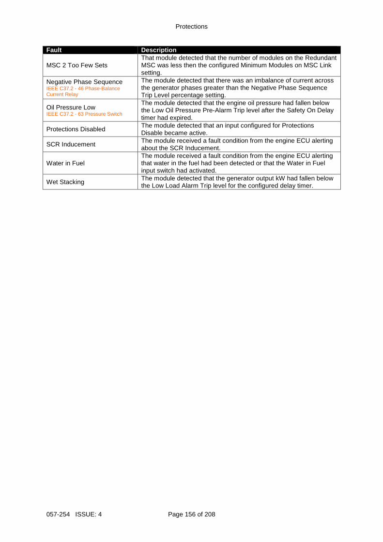
Protections
057-254 ISSUE: 4 Page 156 of 208
Fault Description
MSC 2 Too Few Sets That module detected that the number of modules on the Redundant MSC was less then the configured Minimum Modules on MSC Link setting.
Negative Phase Sequence IEEE C37.2 - 46 Phase-Balance Current Relay
The module detected that there was an imbalance of current across the generator phases greater than the Negative Phase Sequence Trip Level percentage setting.
Oil Pressure Low IEEE C37.2 - 63 Pressure Switch
The module detected that the engine oil pressure had fallen below the Low Oil Pressure Pre-Alarm Trip level after the Safety On Delay timer had expired.
Protections Disabled The module detected that an input configured for Protections Disable became active.
SCR Inducement The module received a fault condition from the engine ECU alerting about the SCR Inducement.
Water in Fuel The module received a fault condition from the engine ECU alerting that water in the fuel had been detected or that the Water in Fuel input switch had activated.
Wet Stacking The module detected that the generator output kW had fallen below the Low Load Alarm Trip level for the configured delay timer.
Protections
Page 157 of 208 057-254 ISSUE: 4
6.4 ELECTRICAL TRIP ALARMS
NOTE: The fault condition must be resolved before t he alarm can be reset. If the fault condition remains, it is not possible to reset the alarm (the exception to this is the Coolant Temp High alarm and similar Active From Safety On alarms, as the coolant temperature could be high with the engine at rest). Electrical Trip Alarms are latching and stop the Generator but in a controlled manner. On initiation of the electrical trip condition the module de-activates the Close Gen Output outputs to remove the load from the generator. Once this has occurred the module starts the Cooling Timer and allows the engine to cool off-load before shutting down the engine. To restart the generator the fault must be cleared and the alarm reset. Example: 1/2 Alarms
Gen Over Current Electrical Trip In the event of an alarm the LCD jumps to the alarms page and scrolls through all active alarms.
Electrical Trip Alarms are latching alarms and to remove the fault, press the Stop/Reset Mode button on the module. Fault Description
2130 ID 1 to 4 Analogue Input E to H High
NOTE: Due to module configuration the alarm message that appears on the display may be different. For f urther details of module configuration, refer to DSE Publication: 057-238 DSE8610 MKII Configuration Suite PC Software Manual . The module detected that an analogue input value of a DSE2130 had risen above the Flexible Sensor High Alarm Trip level.
2130 ID 1 to 4 Analogue Input E to H Low
NOTE: Due to module configuration the alarm message that appears on the display may be different. For f urther details of module configuration, refer to DSE Publication: 057-238 DSE8610 MKII Configuration Suite PC Software Manual . The module detected that an analogue input value of a DSE2130 had fallen below the Flexible Sensor Low Alarm Trip level.
2130 ID1 to 4 Digital Input A to H
NOTE: Due to module configuration the alarm message that appears on the display may be different. For f urther details of module configuration, refer to DSE Publication: 057-238 DSE8610 MKII Configuration Suite PC Software Manual . The module detected that a digital input configured to create a fault condition on a DSE2130 expansion module became active and the appropriate LCD message displayed.
Continued over page…
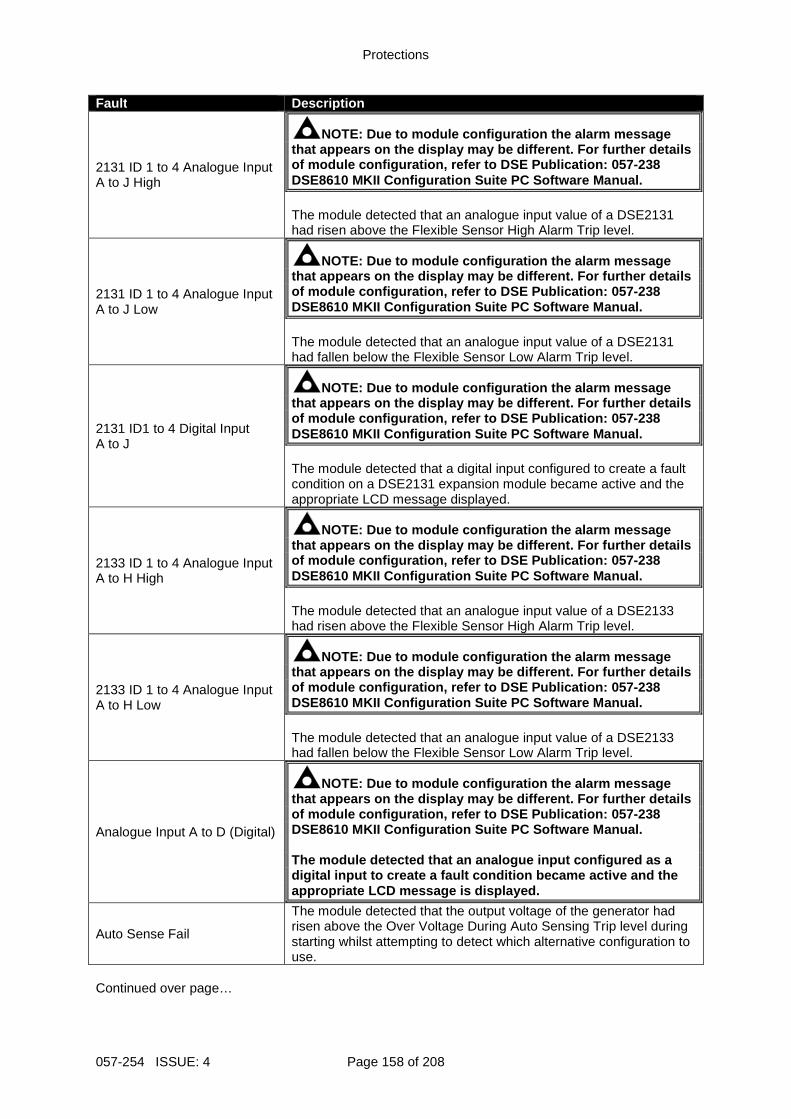
Protections
057-254 ISSUE: 4 Page 158 of 208
Fault Description
2131 ID 1 to 4 Analogue Input A to J High
NOTE: Due to module configuration the alarm message that appears on the display may be different. For f urther details of module configuration, refer to DSE Publication: 057-238 DSE8610 MKII Configuration Suite PC Software Manual . The module detected that an analogue input value of a DSE2131 had risen above the Flexible Sensor High Alarm Trip level.
2131 ID 1 to 4 Analogue Input A to J Low
NOTE: Due to module configuration the alarm message that appears on the display may be different. For f urther details of module configuration, refer to DSE Publication: 057-238 DSE8610 MKII Configuration Suite PC Software Manual . The module detected that an analogue input value of a DSE2131 had fallen below the Flexible Sensor Low Alarm Trip level.
2131 ID1 to 4 Digital Input A to J
NOTE: Due to module configuration the alarm message that appears on the display may be different. For f urther details of module configuration, refer to DSE Publication: 057-238 DSE8610 MKII Configuration Suite PC Software Manual . The module detected that a digital input configured to create a fault condition on a DSE2131 expansion module became active and the appropriate LCD message displayed.
2133 ID 1 to 4 Analogue Input A to H High
NOTE: Due to module configuration the alarm message that appears on the display may be different. For f urther details of module configuration, refer to DSE Publication: 057-238 DSE8610 MKII Configuration Suite PC Software Manual . The module detected that an analogue input value of a DSE2133 had risen above the Flexible Sensor High Alarm Trip level.
2133 ID 1 to 4 Analogue Input A to H Low
NOTE: Due to module configuration the alarm message that appears on the display may be different. For f urther details of module configuration, refer to DSE Publication: 057-238 DSE8610 MKII Configuration Suite PC Software Manual . The module detected that an analogue input value of a DSE2133 had fallen below the Flexible Sensor Low Alarm Trip level.
Analogue Input A to D (Digital)
NOTE: Due to module configuration the alarm message that appears on the display may be different. For f urther details of module configuration, refer to DSE Publication: 057-238 DSE8610 MKII Configuration Suite PC Software Manual . The module detected that an analogue input configur ed as a digital input to create a fault condition became ac tive and the appropriate LCD message is displayed.
Auto Sense Fail
The module detected that the output voltage of the generator had risen above the Over Voltage During Auto Sensing Trip level during starting whilst attempting to detect which alternative configuration to use.
Continued over page…
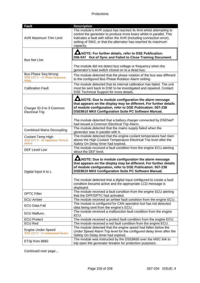
Protections
Page 159 of 208 057-254 ISSUE: 4
Fault Description
AVR Maximum Trim Limit
The module’s AVR output has reached its limit whilst attempting to control the generator to produce more kvars whilst in parallel. This indicates a fault with either the AVR (including connection error), setting of SW2, or that the alternator has reached its maximum capacity.
Bus Not Live
NOTE: For further details, refer to DSE Publication : 056-047 Out of Sync and Failed to Close Training Document . The module did not detect bus voltage or frequency when the generator’s load switch closed on to a dead bus.
Bus Phase Seq Wrong IEEE C37.2 – 47 Phase Sequence Relay
The module detected that the phase rotation of the bus was different to the configured Bus Phase Rotation Alarm setting.
Calibration Fault The module detected that its internal calibration has failed. The unit must be sent back to DSE to be investigated and repaired. Contact DSE Technical Support for more details.
Charger ID 0 to 3 Common Electrical Trip
NOTE: Due to module configuration the alarm message that appears on the display may be different. For f urther details of module configuration, refer to DSE Publication: 057-238 DSE8610 MKII Configuration Suite PC Software Manual . The module detected that a battery charger connected by DSENet®
had issued a Common Electrical Trip Alarm.
Combined Mains Decoupling The module detected that the mains supply failed when the generator was in parallel with it.
Coolant Temp High IEEE C37.2 – 26 Apparatus Thermal Device
The module detected that the engine coolant temperature had risen above the High Coolant Temperature Electrical Trip level after the Safety On Delay timer had expired.
DEF Level Low The module received a fault condition from the engine ECU alerting about the DEF level.
Digital Input A to L
NOTE: Due to module configuration the alarm message that appears on the display may be different. For f urther details of module configuration, refer to DSE Publication: 057-238 DSE8610 MKII Configuration Suite PC Software Manual . The module detected that a digital input configured to create a fault condition became active and the appropriate LCD message is displayed.
DPTC Filter The module received a fault condition from the engine ECU alerting that the DPF/DPTC had activated.
ECU Amber The module received an amber fault condition from the engine ECU.
ECU Data Fail The module is configured for CAN operation but has not detected data being sent from the engine’s ECU.
ECU Malfunc. The module received a malfunction fault condition from the engine ECU.
ECU Protect The module received a protect fault condition from the engine ECU. ECU Red The module received a red fault condition from the engine ECU.
Engine Under Speed IEEE C37.2 - 14 Underspeed Device
The module detected that the engine speed had fallen below the Under Speed Alarm Trip level for the configured delay timer after the Safety On Delay timer had expired.
ETrip from 8660 The module was instructed by the DSE8660 over the MSC link to trip open the generator breaker for protection purposes.
Continued over page…
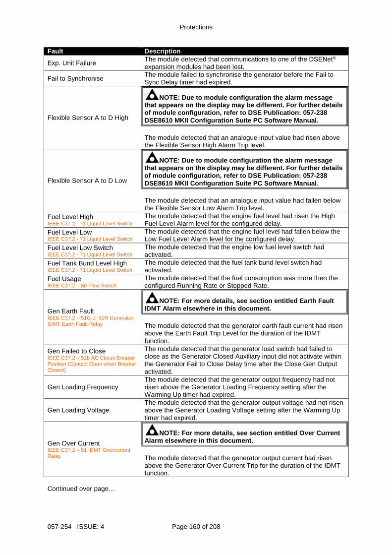
Protections
057-254 ISSUE: 4 Page 160 of 208
Fault Description
Exp. Unit Failure The module detected that communications to one of the DSENet® expansion modules had been lost.
Fail to Synchronise The module failed to synchronise the generator before the Fail to Sync Delay timer had expired.
Flexible Sensor A to D High
NOTE: Due to module configuration the alarm message that appears on the display may be different. For f urther details of module configuration, refer to DSE Publication: 057-238 DSE8610 MKII Configuration Suite PC Software Manual . The module detected that an analogue input value had risen above the Flexible Sensor High Alarm Trip level.
Flexible Sensor A to D Low
NOTE: Due to module configuration the alarm message that appears on the display may be different. For f urther details of module configuration, refer to DSE Publication: 057-238 DSE8610 MKII Configuration Suite PC Software Manual . The module detected that an analogue input value had fallen below the Flexible Sensor Low Alarm Trip level.
Fuel Level High IEEE C37.2 - 71 Liquid Level Switch
The module detected that the engine fuel level had risen the High Fuel Level Alarm level for the configured delay.
Fuel Level Low IEEE C37.2 - 71 Liquid Level Switch
The module detected that the engine fuel level had fallen below the Low Fuel Level Alarm level for the configured delay
Fuel Level Low Switch IEEE C37.2 - 71 Liquid Level Switch
The module detected that the engine low fuel level switch had activated.
Fuel Tank Bund Level High IEEE C37.2 - 71 Liquid Level Switch
The module detected that the fuel tank bund level switch had activated.
Fuel Usage IEEE C37.2 – 80 Flow Switch
The module detected that the fuel consumption was more then the configured Running Rate or Stopped Rate.
Gen Earth Fault IEEE C37.2 – 51G or 51N Generator IDMT Earth Fault Relay
NOTE: For more details, see section entitled Earth Fault IDMT Alarm elsewhere in this document. The module detected that the generator earth fault current had risen above the Earth Fault Trip Level for the duration of the IDMT function.
Gen Failed to Close IEEE C37.2 – 52b AC Circuit Breaker Position (Contact Open when Breaker Closed)
The module detected that the generator load switch had failed to close as the Generator Closed Auxiliary input did not activate within the Generator Fail to Close Delay time after the Close Gen Output activated.
Gen Loading Frequency The module detected that the generator output frequency had not risen above the Generator Loading Frequency setting after the Warming Up timer had expired.
Gen Loading Voltage The module detected that the generator output voltage had not risen above the Generator Loading Voltage setting after the Warming Up timer had expired.
Gen Over Current IEEE C37.2 – 51 IDMT Overcurrent Relay
NOTE: For more details, see section entitled Over C urrent Alarm elsewhere in this document. The module detected that the generator output current had risen above the Generator Over Current Trip for the duration of the IDMT function.
Continued over page…
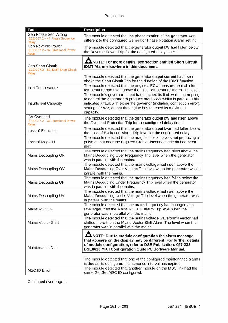
Protections
Page 161 of 208 057-254 ISSUE: 4
Fault Description Gen Phase Seq Wrong IEEE C37.2 – 47 Phase Sequence Relay
The module detected that the phase rotation of the generator was different to the configured Generator Phase Rotation Alarm setting.
Gen Reverse Power IEEE C37.2 – 32 Directional Power Relay
The module detected that the generator output kW had fallen below the Reverse Power Trip for the configured delay timer.
Gen Short Circuit IEEE C37.2 – 51 IDMT Short Circuit Relay
NOTE: For more details, see section entitled Short Circuit IDMT Alarm elsewhere in this document. The module detected that the generator output current had risen above the Short Circuit Trip for the duration of the IDMT function.
Inlet Temperature The module detected that the engine’s ECU measurement of inlet temperature had risen above the Inlet Temperature Alarm Trip level.
Insufficient Capacity
The module’s governor output has reached its limit whilst attempting to control the generator to produce more kWs whilst in parallel. This indicates a fault with either the governor (including connection error), setting of SW2, or that the engine has reached its maximum capacity.
kW Overload IEEE C37.2 – 32 Directional Power Relay
The module detected that the generator output kW had risen above the Overload Protection Trip for the configured delay timer.
Loss of Excitation The module detected that the generator output kvar had fallen below the Loss of Excitation Alarm Trip level for the configured delay.
Loss of Mag-PU The module detected that the magnetic pick up was not producing a pulse output after the required Crank Disconnect criteria had been met.
Mains Decoupling OF The module detected that the mains frequency had risen above the Mains Decoupling Over Frequency Trip level when the generator was in parallel with the mains.
Mains Decoupling OV The module detected that the mains voltage had risen above the Mains Decoupling Over Voltage Trip level when the generator was in parallel with the mains.
Mains Decoupling UF The module detected that the mains frequency had fallen below the Mains Decoupling Under Frequency Trip level when the generator was in parallel with the mains.
Mains Decoupling UV The module detected that the mains voltage had risen above the Mains Decoupling Under Voltage Trip level when the generator was in parallel with the mains.
Mains ROCOF The module detected that the mains frequency had changed at a rate larger then the Mains ROCOF Alarm Trip level when the generator was in parallel with the mains.
Mains Vector Shift The module detected that the mains voltage waveform’s vector had shifted more then the Mains Vector Shift Alarm Trip level when the generator was in parallel with the mains.
Maintenance Due
NOTE: Due to module configuration the alarm message that appears on the display may be different. For f urther details of module configuration, refer to DSE Publication: 057-238 DSE8610 MKII Configuration Suite PC Software Manual . The module detected that one of the configured maintenance alarms is due as its configured maintenance interval has expired.
MSC ID Error The module detected that another module on the MSC link had the same GenSet MSC ID configured.
Continued over page…
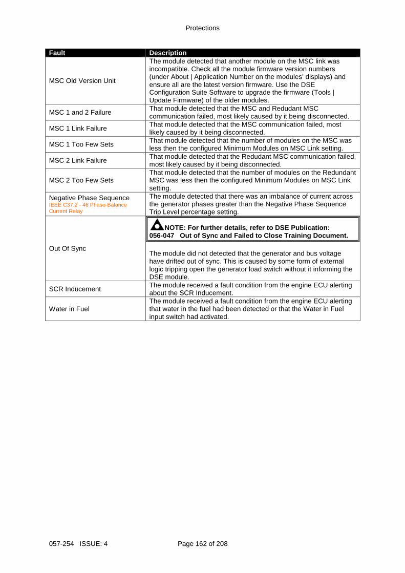
Protections
057-254 ISSUE: 4 Page 162 of 208
Fault Description
MSC Old Version Unit
The module detected that another module on the MSC link was incompatible. Check all the module firmware version numbers (under About | Application Number on the modules’ displays) and ensure all are the latest version firmware. Use the DSE Configuration Suite Software to upgrade the firmware (Tools | Update Firmware) of the older modules.
MSC 1 and 2 Failure That module detected that the MSC and Redudant MSC communication failed, most likely caused by it being disconnected.
MSC 1 Link Failure That module detected that the MSC communication failed, most likely caused by it being disconnected.
MSC 1 Too Few Sets That module detected that the number of modules on the MSC was less then the configured Minimum Modules on MSC Link setting.
MSC 2 Link Failure That module detected that the Redudant MSC communication failed, most likely caused by it being disconnected.
MSC 2 Too Few Sets That module detected that the number of modules on the Redundant MSC was less then the configured Minimum Modules on MSC Link setting.
Negative Phase Sequence IEEE C37.2 - 46 Phase-Balance Current Relay
The module detected that there was an imbalance of current across the generator phases greater than the Negative Phase Sequence Trip Level percentage setting.
Out Of Sync
NOTE: For further details, refer to DSE Publication : 056-047 Out of Sync and Failed to Close Training Document . The module did not detected that the generator and bus voltage have drifted out of sync. This is caused by some form of external logic tripping open the generator load switch without it informing the DSE module.
SCR Inducement The module received a fault condition from the engine ECU alerting about the SCR Inducement.
Water in Fuel The module received a fault condition from the engine ECU alerting that water in the fuel had been detected or that the Water in Fuel input switch had activated.
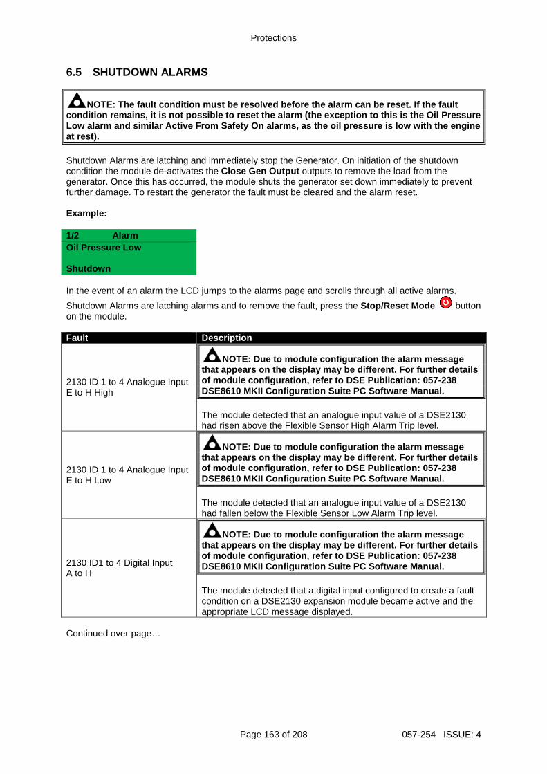
Protections
Page 163 of 208 057-254 ISSUE: 4
6.5 SHUTDOWN ALARMS
NOTE: The fault condition must be resolved before t he alarm can be reset. If the fault condition remains, it is not possible to reset the alarm (the exception to this is the Oil Pressure Low alarm and similar Active From Safety On alarms, as the oil pressure is low with the engine at rest). Shutdown Alarms are latching and immediately stop the Generator. On initiation of the shutdown condition the module de-activates the Close Gen Output outputs to remove the load from the generator. Once this has occurred, the module shuts the generator set down immediately to prevent further damage. To restart the generator the fault must be cleared and the alarm reset. Example: 1/2 Alarm Oil Pressure Low Shutdown
In the event of an alarm the LCD jumps to the alarms page and scrolls through all active alarms.
Shutdown Alarms are latching alarms and to remove the fault, press the Stop/Reset Mode button on the module. Fault Description
2130 ID 1 to 4 Analogue Input E to H High
NOTE: Due to module configuration the alarm message that appears on the display may be different. For f urther details of module configuration, refer to DSE Publication: 057-238 DSE8610 MKII Configuration Suite PC Software Manual . The module detected that an analogue input value of a DSE2130 had risen above the Flexible Sensor High Alarm Trip level.
2130 ID 1 to 4 Analogue Input E to H Low
NOTE: Due to module configuration the alarm message that appears on the display may be different. For f urther details of module configuration, refer to DSE Publication: 057-238 DSE8610 MKII Configuration Suite PC Software Manual . The module detected that an analogue input value of a DSE2130 had fallen below the Flexible Sensor Low Alarm Trip level.
2130 ID1 to 4 Digital Input A to H
NOTE: Due to module configuration the alarm message that appears on the display may be different. For f urther details of module configuration, refer to DSE Publication: 057-238 DSE8610 MKII Configuration Suite PC Software Manual . The module detected that a digital input configured to create a fault condition on a DSE2130 expansion module became active and the appropriate LCD message displayed.
Continued over page…
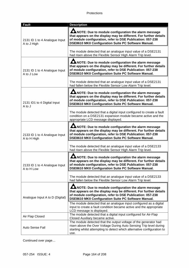
Protections
057-254 ISSUE: 4 Page 164 of 208
Fault Description
2131 ID 1 to 4 Analogue Input A to J High
NOTE: Due to module configuration the alarm message that appears on the display may be different. For f urther details of module configuration, refer to DSE Publication: 057-238 DSE8610 MKII Configuration Suite PC Software Manual . The module detected that an analogue input value of a DSE2131 had risen above the Flexible Sensor High Alarm Trip level.
2131 ID 1 to 4 Analogue Input A to J Low
NOTE: Due to module configuration the alarm message that appears on the display may be different. For f urther details of module configuration, refer to DSE Publication: 057-238 DSE8610 MKII Configuration Suite PC Software Manual . The module detected that an analogue input value of a DSE2131 had fallen below the Flexible Sensor Low Alarm Trip level.
2131 ID1 to 4 Digital Input A to J
NOTE: Due to module configuration the alarm message that appears on the display may be different. For f urther details of module configuration, refer to DSE Publication: 057-238 DSE8610 MKII Configuration Suite PC Software Manual . The module detected that a digital input configured to create a fault condition on a DSE2131 expansion module became active and the appropriate LCD message displayed.
2133 ID 1 to 4 Analogue Input A to H High
NOTE: Due to module configuration the alarm message that appears on the display may be different. For f urther details of module configuration, refer to DSE Publication: 057-238 DSE8610 MKII Configuration Suite PC Software Manual . The module detected that an analogue input value of a DSE2133 had risen above the Flexible Sensor High Alarm Trip level.
2133 ID 1 to 4 Analogue Input A to H Low
NOTE: Due to module configuration the alarm message that appears on the display may be different. For f urther details of module configuration, refer to DSE Publication: 057-238 DSE8610 MKII Configuration Suite PC Software Manual . The module detected that an analogue input value of a DSE2133 had fallen below the Flexible Sensor Low Alarm Trip level.
Analogue Input A to D (Digital)
NOTE: Due to module configuration the alarm message that appears on the display may be different. For f urther details of module configuration, refer to DSE Publication: 057-238 DSE8610 MKII Configuration Suite PC Software Manual . The module detected that an analogue input configured as a digital input to create a fault condition became active and the appropriate LCD message is displayed.
Air Flap Closed The module detected that a digital input configured for Air-Flap Closed Auxiliary became active.
Auto Sense Fail
The module detected that the output voltage of the generator had risen above the Over Voltage During Auto Sensing Trip level during starting whilst attempting to detect which alternative configuration to use.
Continued over page…
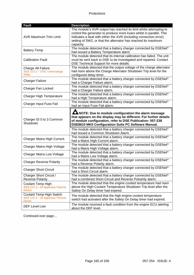
Protections
Page 165 of 208 057-254 ISSUE: 4
Fault Description
AVR Maximum Trim Limit
The module’s AVR output has reached its limit whilst attempting to control the generator to produce more kvars whilst in parallel. This indicates a fault with either the AVR (including connection error), setting of SW2, or that the alternator has reached its maximum capacity.
Battery Temp The module detected that a battery charger connected by DSENet®
had issued a Battery Temperature alarm
Calibration Fault The module detected that its internal calibration has failed. The unit must be sent back to DSE to be investigated and repaired. Contact DSE Technical Support for more details.
Charge Alt Failure IEEE C37.2 – 27DC Undervoltage Relay
The module detected that the output voltage of the charge alternator had risen above the Charge Alternator Shutdown Trip level for the configured delay timer.
Charger Failure The module detected that a battery charger connected by DSENet®
had a Charger Failure alarm.
Charger Fan Locked The module detected that a battery charger connected by DSENet®
had a Charger Failure alarm.
Charger High Temperature The module detected that a battery charger connected by DSENet®
had a High Temperature alarm.
Charger Input Fuse Fail The module detected that a battery charger connected by DSENet®
had an Input Fuse Fail alarm.
Charger ID 0 to 3 Common Shutdown
NOTE: Due to module configuration the alarm message that appears on the display may be different. For f urther details of module configuration, refer to DSE Publication: 057-238 DSE8610 MKII Configuration Suite PC Software Manual . The module detected that a battery charger connected by DSENet®
had issued a Common Shutdown Alarm.
Charger Mains High Current The module detected that a battery charger connected by DSENet®
had a Mains High Current alarm.
Charger Mains High Voltage The module detected that a battery charger connected by DSENet®
had a Mains High Voltage alarm.
Charger Mains Low Voltage The module detected that a battery charger connected by DSENet®
had a Mains Low Voltage alarm.
Charger Reverse Polarity The module detected that a battery charger connected by DSENet®
had a Reverse Polarity alarm.
Charger Short Circuit The module detected that a battery charger connected by DSENet®
had a Short Circuit alarm. Charger Short Circuit / Reverse Polarity
The module detected that a battery charger connected by DSENet®
had a combined Short Circuit and Reverse Poloarity alarm.
Coolant Temp High IEEE C37.2 – 26 Apparatus Thermal Device
The module detected that the engine coolant temperature had risen above the High Coolant Temperature Shutdown Trip level after the Safety On Delay timer had expired.
Coolant Temp High Switch IEEE C37.2 – 26 Apparatus Thermal Device
The module detected that the high engine coolant temperature switch had activated after the Safety On Delay timer had expired.
DEF Level Low The module received a fault condition from the engine ECU alerting about the DEF level.
Continued over page…
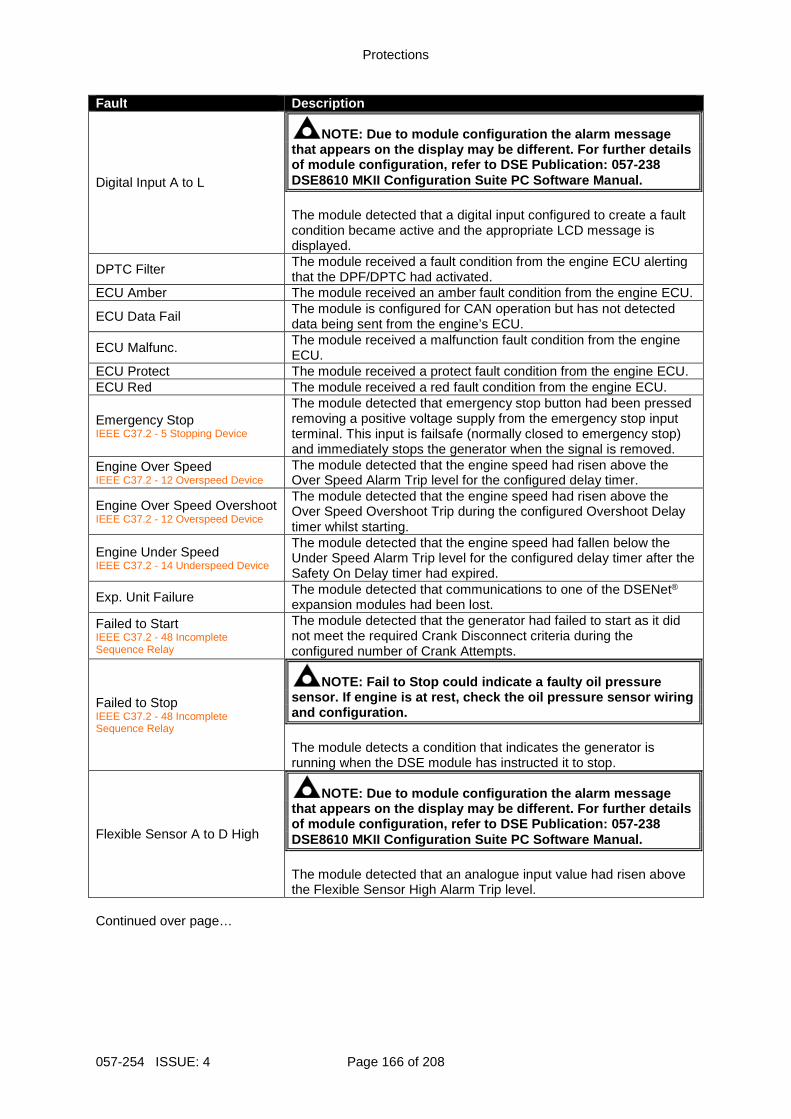
Protections
057-254 ISSUE: 4 Page 166 of 208
Fault Description
Digital Input A to L
NOTE: Due to module configuration the alarm message that appears on the display may be different. For f urther details of module configuration, refer to DSE Publication: 057-238 DSE8610 MKII Configuration Suite PC Software Manual . The module detected that a digital input configured to create a fault condition became active and the appropriate LCD message is displayed.
DPTC Filter The module received a fault condition from the engine ECU alerting that the DPF/DPTC had activated.
ECU Amber The module received an amber fault condition from the engine ECU.
ECU Data Fail The module is configured for CAN operation but has not detected data being sent from the engine’s ECU.
ECU Malfunc. The module received a malfunction fault condition from the engine ECU.
ECU Protect The module received a protect fault condition from the engine ECU. ECU Red The module received a red fault condition from the engine ECU.
Emergency Stop IEEE C37.2 - 5 Stopping Device
The module detected that emergency stop button had been pressed removing a positive voltage supply from the emergency stop input terminal. This input is failsafe (normally closed to emergency stop) and immediately stops the generator when the signal is removed.
Engine Over Speed IEEE C37.2 - 12 Overspeed Device
The module detected that the engine speed had risen above the Over Speed Alarm Trip level for the configured delay timer.
Engine Over Speed Overshoot IEEE C37.2 - 12 Overspeed Device
The module detected that the engine speed had risen above the Over Speed Overshoot Trip during the configured Overshoot Delay timer whilst starting.
Engine Under Speed IEEE C37.2 - 14 Underspeed Device
The module detected that the engine speed had fallen below the Under Speed Alarm Trip level for the configured delay timer after the Safety On Delay timer had expired.
Exp. Unit Failure The module detected that communications to one of the DSENet® expansion modules had been lost.
Failed to Start IEEE C37.2 - 48 Incomplete Sequence Relay
The module detected that the generator had failed to start as it did not meet the required Crank Disconnect criteria during the configured number of Crank Attempts.
Failed to Stop IEEE C37.2 - 48 Incomplete Sequence Relay
NOTE: Fail to Stop could indicate a faulty oil pressure sensor. If engine is at rest, check the oil pressur e sensor wiring and configuration. The module detects a condition that indicates the generator is running when the DSE module has instructed it to stop.
Flexible Sensor A to D High
NOTE: Due to module configuration the alarm message that appears on the display may be different. For f urther details of module configuration, refer to DSE Publication: 057-238 DSE8610 MKII Configuration Suite PC Software Manual . The module detected that an analogue input value had risen above the Flexible Sensor High Alarm Trip level.
Continued over page…
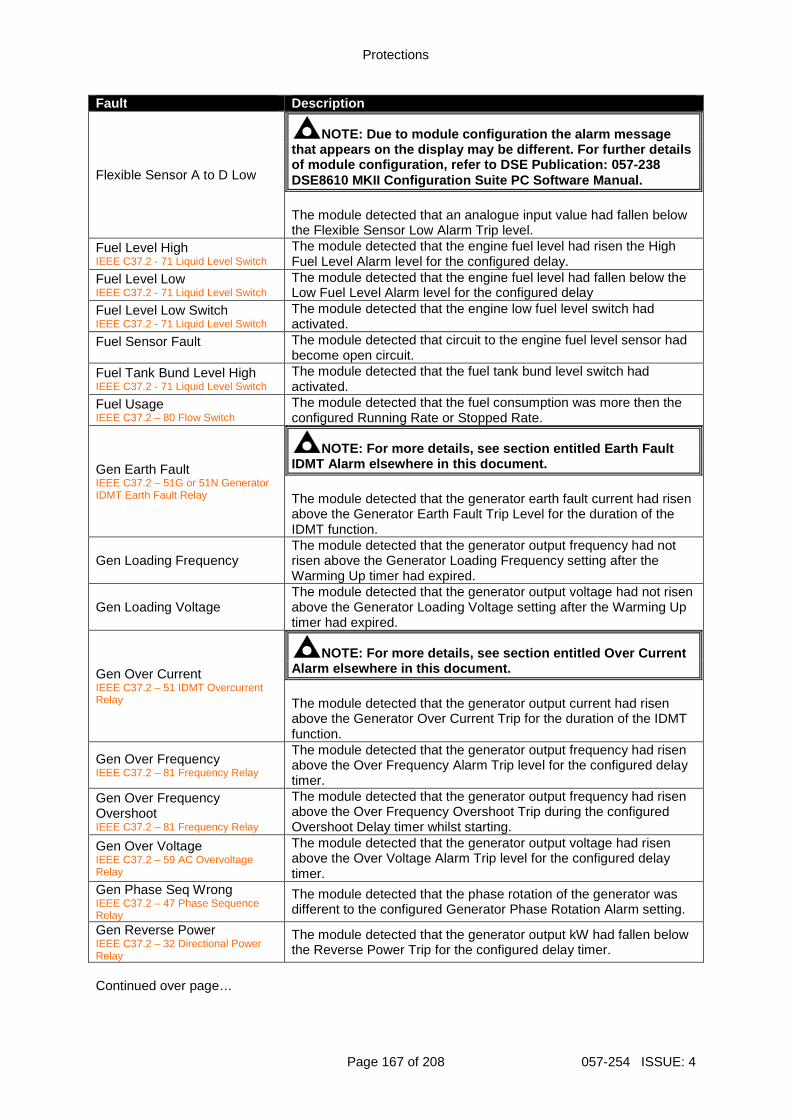
Protections
Page 167 of 208 057-254 ISSUE: 4
Fault Description
Flexible Sensor A to D Low
NOTE: Due to module configuration the alarm message that appears on the display may be different. For f urther details of module configuration, refer to DSE Publication: 057-238 DSE8610 MKII Configuration Suite PC Software Manual . The module detected that an analogue input value had fallen below the Flexible Sensor Low Alarm Trip level.
Fuel Level High IEEE C37.2 - 71 Liquid Level Switch
The module detected that the engine fuel level had risen the High Fuel Level Alarm level for the configured delay.
Fuel Level Low IEEE C37.2 - 71 Liquid Level Switch
The module detected that the engine fuel level had fallen below the Low Fuel Level Alarm level for the configured delay
Fuel Level Low Switch IEEE C37.2 - 71 Liquid Level Switch
The module detected that the engine low fuel level switch had activated.
Fuel Sensor Fault
The module detected that circuit to the engine fuel level sensor had become open circuit.
Fuel Tank Bund Level High IEEE C37.2 - 71 Liquid Level Switch
The module detected that the fuel tank bund level switch had activated.
Fuel Usage IEEE C37.2 – 80 Flow Switch
The module detected that the fuel consumption was more then the configured Running Rate or Stopped Rate.
Gen Earth Fault IEEE C37.2 – 51G or 51N Generator IDMT Earth Fault Relay
NOTE: For more details, see section entitled Earth Fault IDMT Alarm elsewhere in this document. The module detected that the generator earth fault current had risen above the Generator Earth Fault Trip Level for the duration of the IDMT function.
Gen Loading Frequency The module detected that the generator output frequency had not risen above the Generator Loading Frequency setting after the Warming Up timer had expired.
Gen Loading Voltage The module detected that the generator output voltage had not risen above the Generator Loading Voltage setting after the Warming Up timer had expired.
Gen Over Current IEEE C37.2 – 51 IDMT Overcurrent Relay
NOTE: For more details, see section entitled Over C urrent Alarm elsewhere in this document. The module detected that the generator output current had risen above the Generator Over Current Trip for the duration of the IDMT function.
Gen Over Frequency IEEE C37.2 – 81 Frequency Relay
The module detected that the generator output frequency had risen above the Over Frequency Alarm Trip level for the configured delay timer.
Gen Over Frequency Overshoot IEEE C37.2 – 81 Frequency Relay
The module detected that the generator output frequency had risen above the Over Frequency Overshoot Trip during the configured Overshoot Delay timer whilst starting.
Gen Over Voltage IEEE C37.2 – 59 AC Overvoltage Relay
The module detected that the generator output voltage had risen above the Over Voltage Alarm Trip level for the configured delay timer.
Gen Phase Seq Wrong IEEE C37.2 – 47 Phase Sequence Relay
The module detected that the phase rotation of the generator was different to the configured Generator Phase Rotation Alarm setting.
Gen Reverse Power IEEE C37.2 – 32 Directional Power Relay
The module detected that the generator output kW had fallen below the Reverse Power Trip for the configured delay timer.
Continued over page…
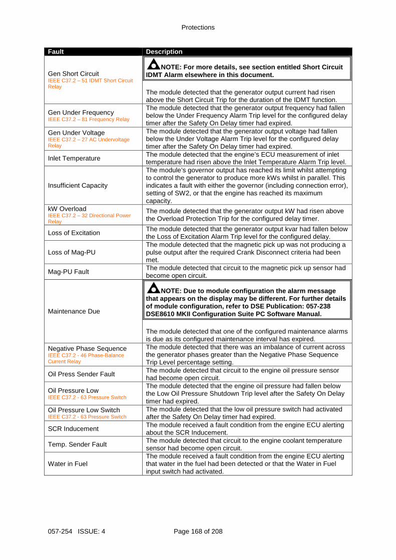
Protections
057-254 ISSUE: 4 Page 168 of 208
Fault Description
Gen Short Circuit IEEE C37.2 – 51 IDMT Short Circuit Relay
NOTE: For more details, see section entitled Short Circuit IDMT Alarm elsewhere in this document. The module detected that the generator output current had risen above the Short Circuit Trip for the duration of the IDMT function.
Gen Under Frequency IEEE C37.2 – 81 Frequency Relay
The module detected that the generator output frequency had fallen below the Under Frequency Alarm Trip level for the configured delay timer after the Safety On Delay timer had expired.
Gen Under Voltage IEEE C37.2 – 27 AC Undervoltage Relay
The module detected that the generator output voltage had fallen below the Under Voltage Alarm Trip level for the configured delay timer after the Safety On Delay timer had expired.
Inlet Temperature The module detected that the engine’s ECU measurement of inlet temperature had risen above the Inlet Temperature Alarm Trip level.
Insufficient Capacity
The module’s governor output has reached its limit whilst attempting to control the generator to produce more kWs whilst in parallel. This indicates a fault with either the governor (including connection error), setting of SW2, or that the engine has reached its maximum capacity.
kW Overload IEEE C37.2 – 32 Directional Power Relay
The module detected that the generator output kW had risen above the Overload Protection Trip for the configured delay timer.
Loss of Excitation The module detected that the generator output kvar had fallen below the Loss of Excitation Alarm Trip level for the configured delay.
Loss of Mag-PU The module detected that the magnetic pick up was not producing a pulse output after the required Crank Disconnect criteria had been met.
Mag-PU Fault The module detected that circuit to the magnetic pick up sensor had become open circuit.
Maintenance Due
NOTE: Due to module configuration the alarm message that appears on the display may be different. For f urther details of module configuration, refer to DSE Publication: 057-238 DSE8610 MKII Configuration Suite PC Software Manual . The module detected that one of the configured maintenance alarms is due as its configured maintenance interval has expired.
Negative Phase Sequence IEEE C37.2 - 46 Phase-Balance Current Relay
The module detected that there was an imbalance of current across the generator phases greater than the Negative Phase Sequence Trip Level percentage setting.
Oil Press Sender Fault The module detected that circuit to the engine oil pressure sensor had become open circuit.
Oil Pressure Low IEEE C37.2 - 63 Pressure Switch
The module detected that the engine oil pressure had fallen below the Low Oil Pressure Shutdown Trip level after the Safety On Delay timer had expired.
Oil Pressure Low Switch IEEE C37.2 - 63 Pressure Switch
The module detected that the low oil pressure switch had activated after the Safety On Delay timer had expired.
SCR Inducement The module received a fault condition from the engine ECU alerting about the SCR Inducement.
Temp. Sender Fault The module detected that circuit to the engine coolant temperature sensor had become open circuit.
Water in Fuel The module received a fault condition from the engine ECU alerting that water in the fuel had been detected or that the Water in Fuel input switch had activated.
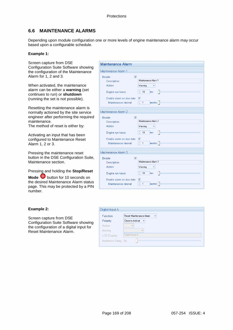
Protections
Page 169 of 208 057-254 ISSUE: 4
6.6 MAINTENANCE ALARMS Depending upon module configuration one or more levels of engine maintenance alarm may occur based upon a configurable schedule. Example 1: Screen capture from DSE Configuration Suite Software showing the configuration of the Maintenance Alarm for 1, 2 and 3. When activated, the maintenance alarm can be either a warning (set continues to run) or shutdown (running the set is not possible). Resetting the maintenance alarm is normally actioned by the site service engineer after performing the required maintenance. The method of reset is either by: Activating an input that has been configured to Maintenance Reset Alarm 1, 2 or 3. Pressing the maintenance reset button in the DSE Configuration Suite, Maintenance section. Pressing and holding the Stop/Reset
Mode button for 10 seconds on the desired Maintenance Alarm status page. This may be protected by a PIN number. Example 2: Screen capture from DSE Configuration Suite Software showing the configuration of a digital input for Reset Maintenance Alarm.
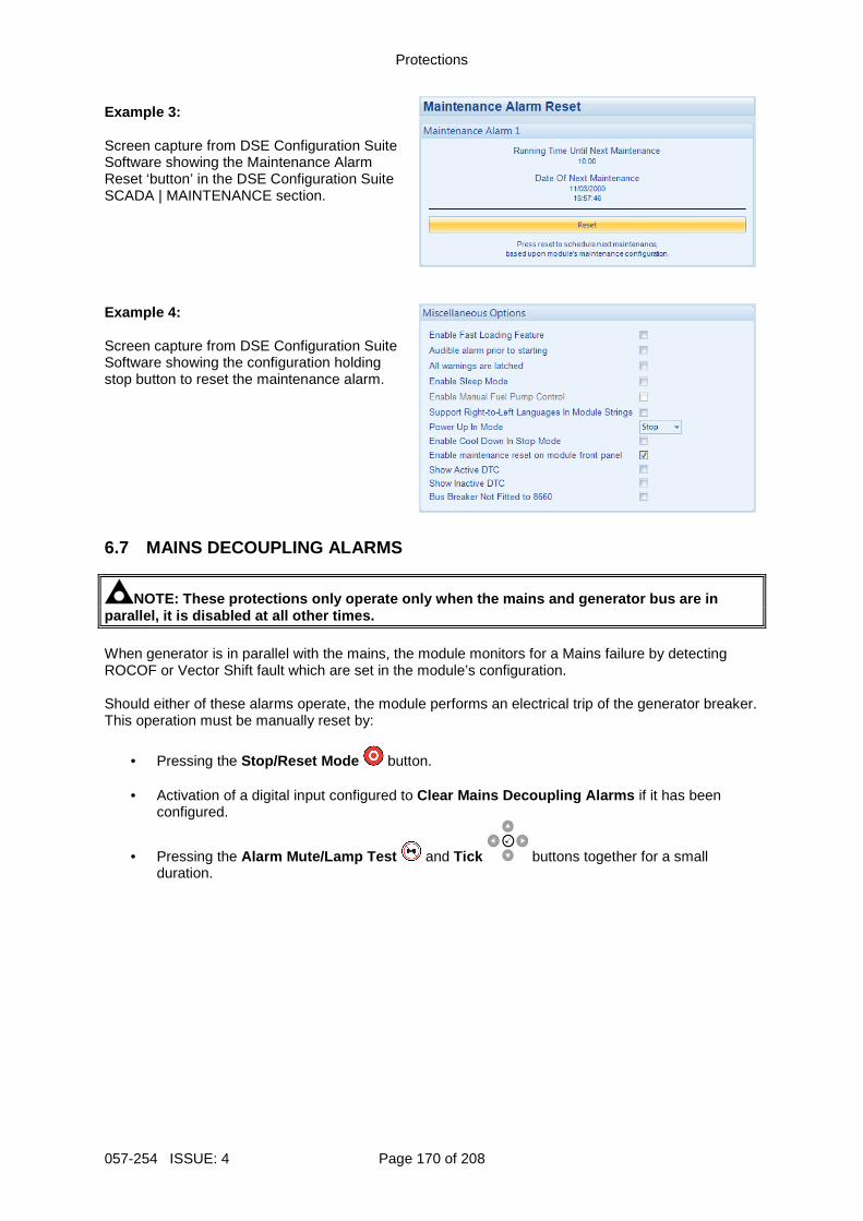
Protections
057-254 ISSUE: 4 Page 170 of 208
Example 3: Screen capture from DSE Configuration Suite Software showing the Maintenance Alarm Reset ‘button’ in the DSE Configuration Suite SCADA | MAINTENANCE section. Example 4: Screen capture from DSE Configuration Suite Software showing the configuration holding stop button to reset the maintenance alarm. 6.7 MAINS DECOUPLING ALARMS
NOTE: These protections only operate only when the mains and generator bus are in parallel, it is disabled at all other times. When generator is in parallel with the mains, the module monitors for a Mains failure by detecting ROCOF or Vector Shift fault which are set in the module’s configuration. Should either of these alarms operate, the module performs an electrical trip of the generator breaker. This operation must be manually reset by:
• Pressing the Stop/Reset Mode button.
• Activation of a digital input configured to Clear Mains Decoupling Alarms if it has been configured.
• Pressing the Alarm Mute/Lamp Test and Tick buttons together for a small duration.
Protections
Page 171 of 208 057-254 ISSUE: 4
6.8 OVER CURRENT ALARM The Over Current Alarm combines a simple warning trip level with a fully functioning IDMT curve for thermal protection. 6.8.1 IMMEDIATE WARNING If the Immediate Warning is enabled, the controller generates a warning alarm as soon as the Trip level is reached. The alarm automatically resets once the generator loading current falls below the Trip level (unless All Warnings are latched is enabled). For further advice, consult the generator supplier.
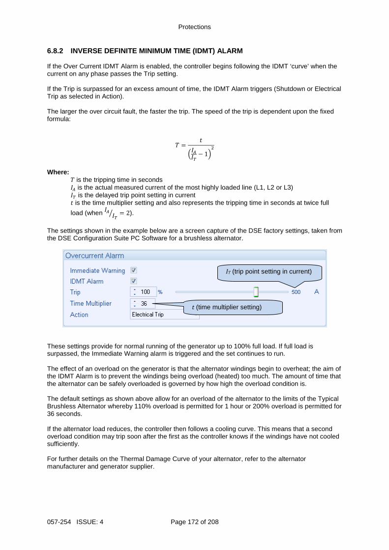
Protections
057-254 ISSUE: 4 Page 172 of 208
6.8.2 INVERSE DEFINITE MINIMUM TIME (IDMT) ALARM If the Over Current IDMT Alarm is enabled, the controller begins following the IDMT ‘curve’ when the current on any phase passes the Trip setting. If the Trip is surpassed for an excess amount of time, the IDMT Alarm triggers (Shutdown or Electrical Trip as selected in Action). The larger the over circuit fault, the faster the trip. The speed of the trip is dependent upon the fixed formula:
= − 1
Where:
is the tripping time in seconds is the actual measured current of the most highly loaded line (L1, L2 or L3) is the delayed trip point setting in current is the time multiplier setting and also represents the tripping time in seconds at twice full
load (when = 2).
The settings shown in the example below are a screen capture of the DSE factory settings, taken from the DSE Configuration Suite PC Software for a brushless alternator.
These settings provide for normal running of the generator up to 100% full load. If full load is surpassed, the Immediate Warning alarm is triggered and the set continues to run. The effect of an overload on the generator is that the alternator windings begin to overheat; the aim of the IDMT Alarm is to prevent the windings being overload (heated) too much. The amount of time that the alternator can be safely overloaded is governed by how high the overload condition is. The default settings as shown above allow for an overload of the alternator to the limits of the Typical Brushless Alternator whereby 110% overload is permitted for 1 hour or 200% overload is permitted for 36 seconds. If the alternator load reduces, the controller then follows a cooling curve. This means that a second overload condition may trip soon after the first as the controller knows if the windings have not cooled sufficiently. For further details on the Thermal Damage Curve of your alternator, refer to the alternator manufacturer and generator supplier.
t (time multiplier setting)
IT (trip point setting in current)
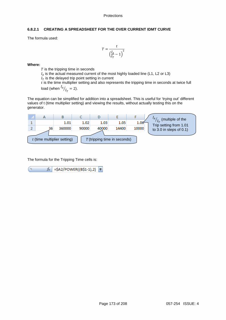
Protections
Page 173 of 208 057-254 ISSUE: 4
6.8.2.1 CREATING A SPREADSHEET FOR THE OVER CURRENT IDMT CURVE The formula used:
= − 1
Where:
is the tripping time in seconds is the actual measured current of the most highly loaded line (L1, L2 or L3) is the delayed trip point setting in current is the time multiplier setting and also represents the tripping time in seconds at twice full
load (when = 2).
The equation can be simplified for addition into a spreadsheet. This is useful for ‘trying out’ different values of t (time multiplier setting) and viewing the results, without actually testing this on the generator.
The formula for the Tripping Time cells is:
(multiple of the
Trip setting from 1.01 to 3.0 in steps of 0.1)
t (time multiplier setting) T (tripping time in seconds)
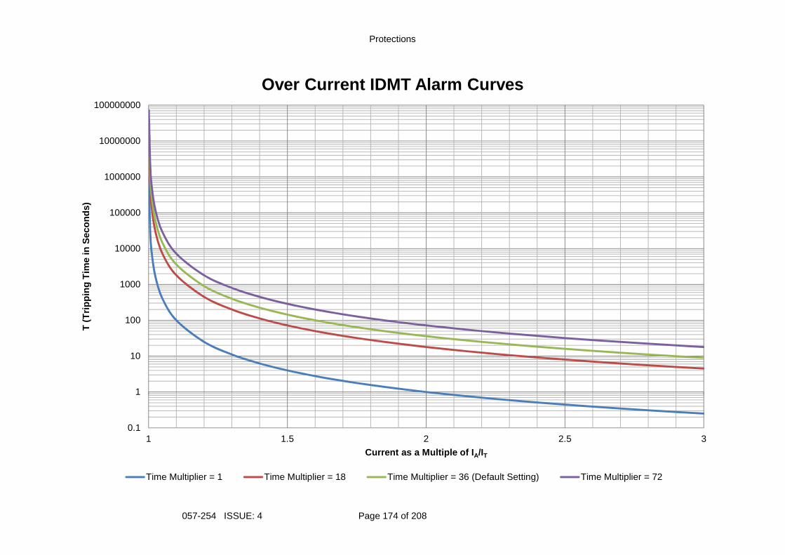
Protections
057-254 ISSUE: 4 Page 174 of 208
0.1
1
10
100
1000
10000
100000
1000000
10000000
100000000
1 1.5 2 2.5 3
T (
Trip
ping
Tim
e in
Sec
onds
)
Current as a Multiple of I A/IT
Over Current IDMT Alarm Curves
Time Multiplier = 1 Time Multiplier = 18 Time Multiplier = 36 (Default Setting) Time Multiplier = 72
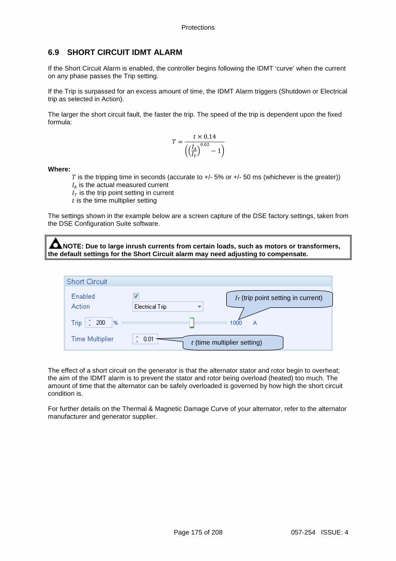
Protections
Page 175 of 208 057-254 ISSUE: 4
6.9 SHORT CIRCUIT IDMT ALARM If the Short Circuit Alarm is enabled, the controller begins following the IDMT ‘curve’ when the current on any phase passes the Trip setting. If the Trip is surpassed for an excess amount of time, the IDMT Alarm triggers (Shutdown or Electrical trip as selected in Action). The larger the short circuit fault, the faster the trip. The speed of the trip is dependent upon the fixed formula:
= × 0.14
.− 1
Where:
is the tripping time in seconds (accurate to +/- 5% or +/- 50 ms (whichever is the greater)) is the actual measured current is the trip point setting in current is the time multiplier setting
The settings shown in the example below are a screen capture of the DSE factory settings, taken from the DSE Configuration Suite software.
NOTE: Due to large inrush currents from certain loa ds, such as motors or transformers, the default settings for the Short Circuit alarm may need adjusting to compensate.
The effect of a short circuit on the generator is that the alternator stator and rotor begin to overheat; the aim of the IDMT alarm is to prevent the stator and rotor being overload (heated) too much. The amount of time that the alternator can be safely overloaded is governed by how high the short circuit condition is. For further details on the Thermal & Magnetic Damage Curve of your alternator, refer to the alternator manufacturer and generator supplier.
t (time multiplier setting)
IT (trip point setting in current)
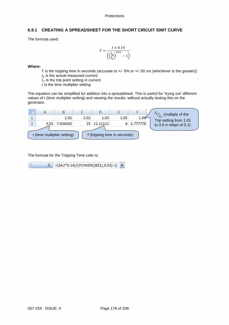
Protections
057-254 ISSUE: 4 Page 176 of 208
6.9.1 CREATING A SPREADSHEET FOR THE SHORT CIRCUIT IDMT CURVE The formula used:
= × 0.14
.− 1
Where:
is the tripping time in seconds (accurate to +/- 5% or +/- 50 ms (whichever is the greater)) is the actual measured current is the trip point setting in current is the time multiplier setting
The equation can be simplified for addition into a spreadsheet. This is useful for ‘trying out’ different values of t (time multiplier setting) and viewing the results, without actually testing this on the generator.
The formula for the Tripping Time cells is:
(multiple of the
Trip setting from 1.01 to 3.0 in steps of 0.1)
t (time multiplier setting) T (tripping time in seconds)
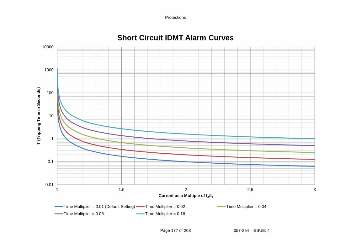
Protections
Page 177 of 208 057-254 ISSUE: 4
0.01
0.1
1
10
100
1000
10000
1 1.5 2 2.5 3
T (
Trip
ping
Tim
e in
Sec
onds
)
Current as a Multiple of I A/IT
Short Circuit IDMT Alarm Curves
Time Multiplier = 0.01 (Default Setting) Time Multiplier = 0.02 Time Multiplier = 0.04
Time Multiplier = 0.08 Time Multiplier = 0.16
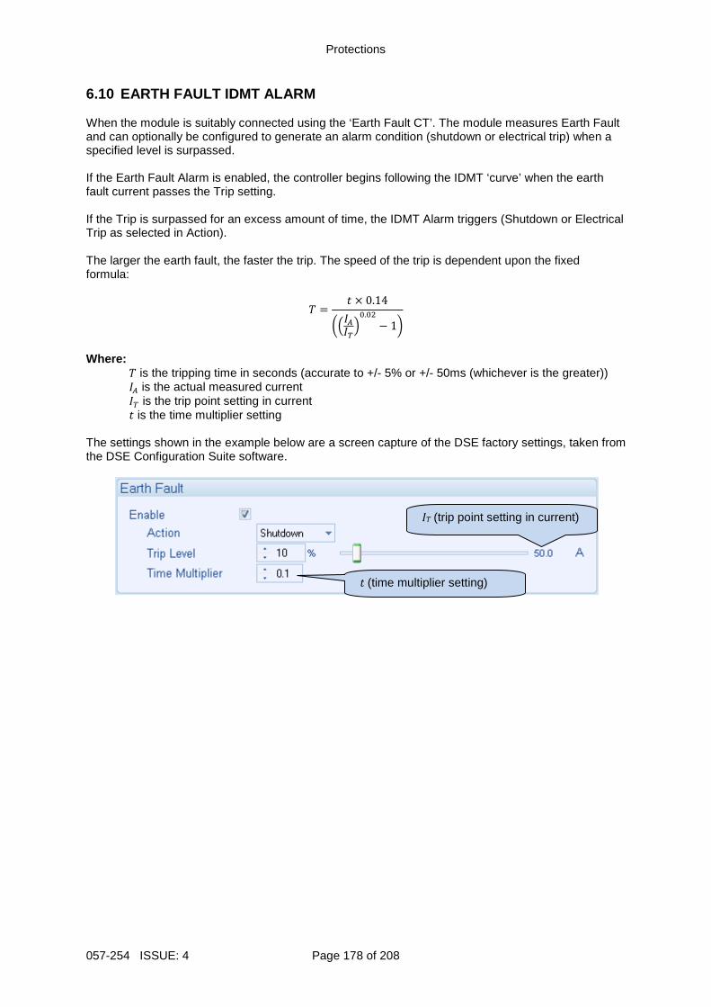
Protections
057-254 ISSUE: 4 Page 178 of 208
6.10 EARTH FAULT IDMT ALARM When the module is suitably connected using the ‘Earth Fault CT’. The module measures Earth Fault and can optionally be configured to generate an alarm condition (shutdown or electrical trip) when a specified level is surpassed. If the Earth Fault Alarm is enabled, the controller begins following the IDMT ‘curve’ when the earth fault current passes the Trip setting. If the Trip is surpassed for an excess amount of time, the IDMT Alarm triggers (Shutdown or Electrical Trip as selected in Action). The larger the earth fault, the faster the trip. The speed of the trip is dependent upon the fixed formula:
= × 0.14
.− 1
Where:
is the tripping time in seconds (accurate to +/- 5% or +/- 50ms (whichever is the greater)) is the actual measured current is the trip point setting in current is the time multiplier setting
The settings shown in the example below are a screen capture of the DSE factory settings, taken from the DSE Configuration Suite software.
t (time multiplier setting)
IT (trip point setting in current)
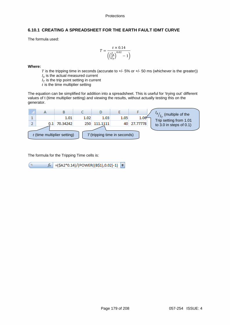
Protections
Page 179 of 208 057-254 ISSUE: 4
6.10.1 CREATING A SPREADSHEET FOR THE EARTH FAULT I DMT CURVE The formula used:
= × 0.14
.− 1
Where:
is the tripping time in seconds (accurate to +/- 5% or +/- 50 ms (whichever is the greater)) is the actual measured current is the trip point setting in current is the time multiplier setting
The equation can be simplified for addition into a spreadsheet. This is useful for ‘trying out’ different values of t (time multiplier setting) and viewing the results, without actually testing this on the generator.
The formula for the Tripping Time cells is:
(multiple of the
Trip setting from 1.01 to 3.0 in steps of 0.1)
t (time multiplier setting) T (tripping time in seconds)
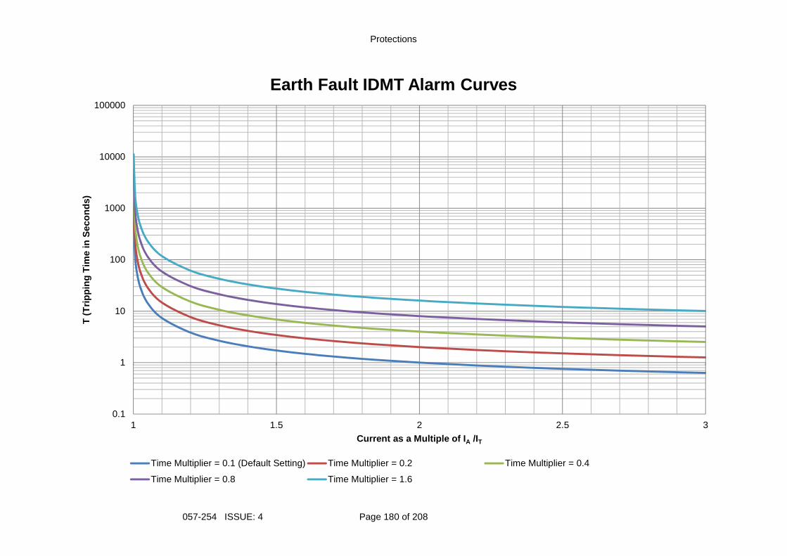
Protections
057-254 ISSUE: 4 Page 180 of 208
0.1
1
10
100
1000
10000
100000
1 1.5 2 2.5 3
T (
Trip
ping
Tim
e in
Sec
onds
)
Current as a Multiple of I A /IT
Earth Fault IDMT Alarm Curves
Time Multiplier = 0.1 (Default Setting) Time Multiplier = 0.2 Time Multiplier = 0.4
Time Multiplier = 0.8 Time Multiplier = 1.6
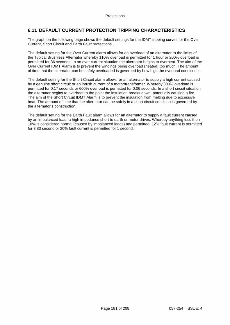
Protections
Page 181 of 208 057-254 ISSUE: 4
6.11 DEFAULT CURRENT PROTECTION TRIPPING CHARACTERI STICS The graph on the following page shows the default settings for the IDMT tripping curves for the Over Current, Short Circuit and Earth Fault protections. The default setting for the Over Current alarm allows for an overload of an alternator to the limits of the Typical Brushless Alternator whereby 110% overload is permitted for 1 hour or 200% overload is permitted for 36 seconds. In an over current situation the alternator begins to overheat. The aim of the Over Current IDMT Alarm is to prevent the windings being overload (heated) too much. The amount of time that the alternator can be safely overloaded is governed by how high the overload condition is. The default setting for the Short Circuit alarm allows for an alternator to supply a high current caused by a genuine short circuit or an inrush current of a motor/transformer. Whereby 300% overload is permitted for 0.17 seconds or 600% overload is permitted for 0.06 seconds. In a short circuit situation the alternator begins to overheat to the point the insulation breaks down, potentially causing a fire. The aim of the Short Circuit IDMT Alarm is to prevent the insulation from melting due to excessive heat. The amount of time that the alternator can be safely in a short circuit condition is governed by the alternator’s construction. The default setting for the Earth Fault alarm allows for an alternator to supply a fault current caused by an imbalanced load, a high impedance short to earth or motor drives. Whereby anything less then 10% is considered normal (caused by imbalanced loads) and permitted, 12% fault current is permitted for 3.83 second or 20% fault current is permitted for 1 second.
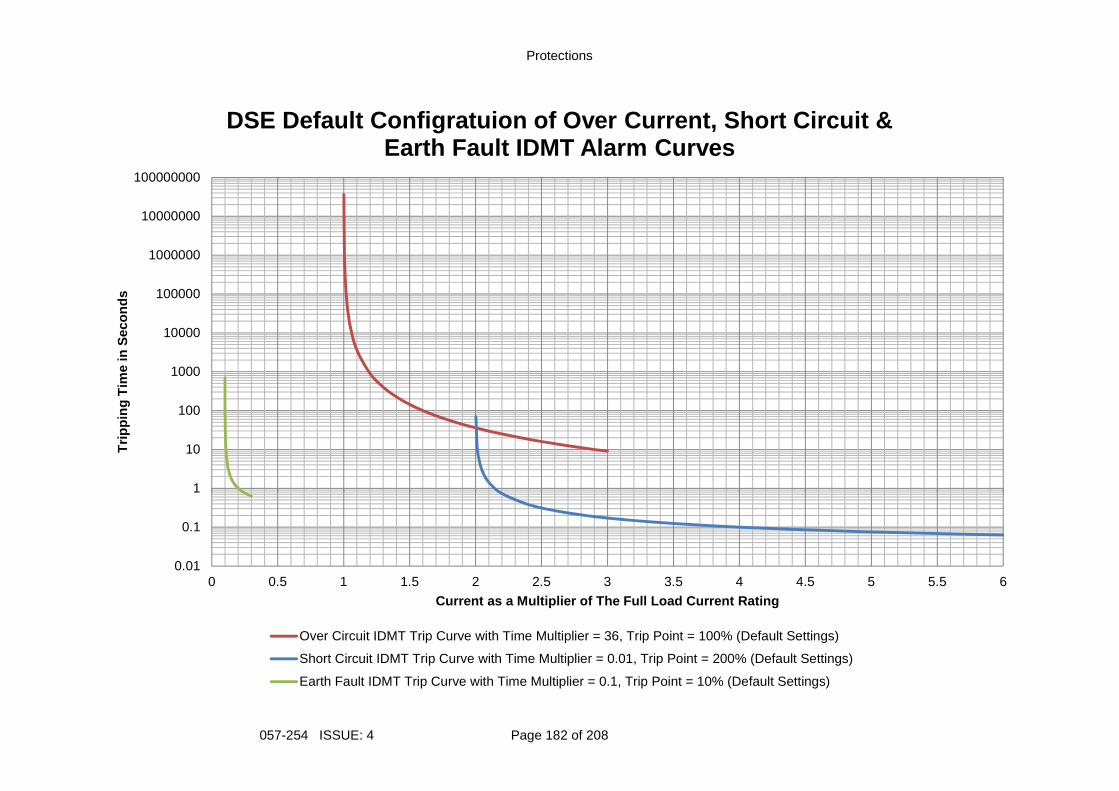
Protections
057-254 ISSUE: 4 Page 182 of 208
0.01
0.1
1
10
100
1000
10000
100000
1000000
10000000
100000000
0 0.5 1 1.5 2 2.5 3 3.5 4 4.5 5 5.5 6
Trip
ping
Tim
e in
Sec
onds
Current as a Multiplier of The Full Load Current Ra ting
DSE Default Configratuion of Over Current, Short Ci rcuit & Earth Fault IDMT Alarm Curves
Over Circuit IDMT Trip Curve with Time Multiplier = 36, Trip Point = 100% (Default Settings)
Short Circuit IDMT Trip Curve with Time Multiplier = 0.01, Trip Point = 200% (Default Settings)
Earth Fault IDMT Trip Curve with Time Multiplier = 0.1, Trip Point = 10% (Default Settings)
Front Panel Configuration
Page 183 of 208 057-254 ISSUE: 4
7 FRONT PANEL CONFIGURATION This configuration mode allows the operator to fully configure the module through its display without the use of the DSE Configuration Suite PC Software. Use the module’s facia buttons to traverse the menu and make value changes to the parameters:
Previous Section
Next Parameter / Increase Valvue
Edit / Save Parameter
Next Section
Previous Parameter / Decrease Valvue
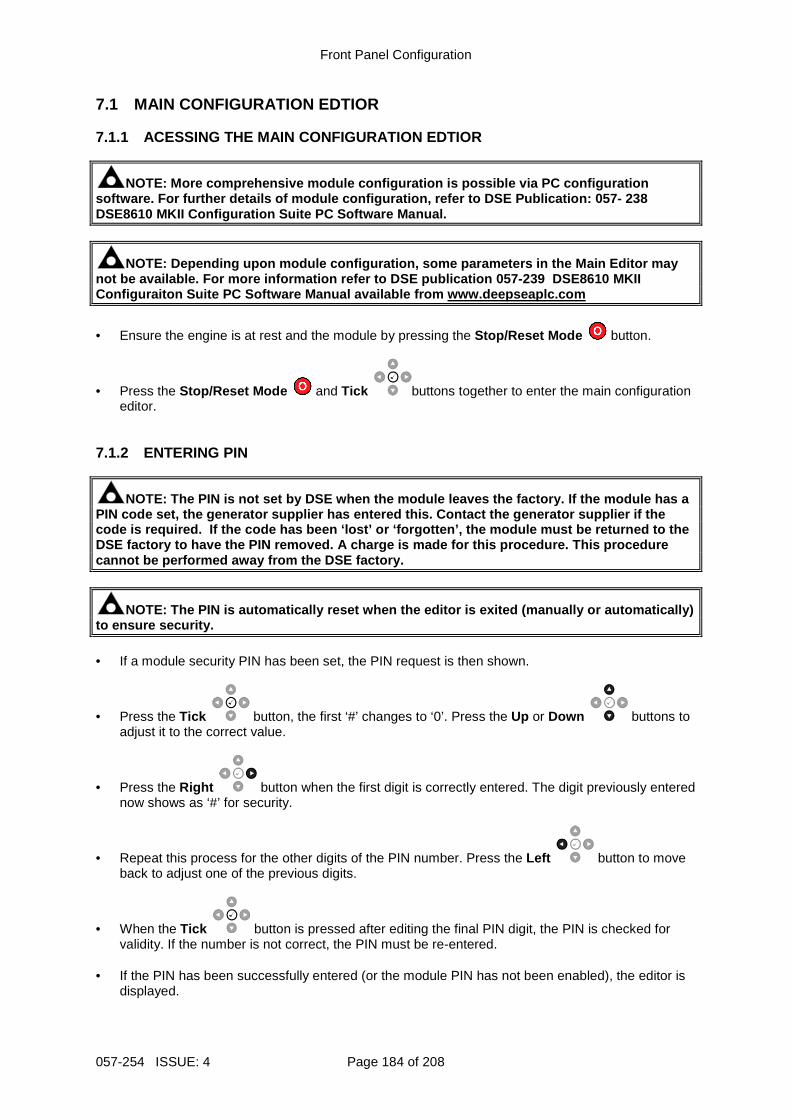
Front Panel Configuration
057-254 ISSUE: 4 Page 184 of 208
7.1 MAIN CONFIGURATION EDTIOR 7.1.1 ACESSING THE MAIN CONFIGURATION EDTIOR
NOTE: More comprehensive module configuration is po ssible via PC configuration software. For further details of module configurati on, refer to DSE Publication: 057- 238 DSE8610 MKII Configuration Suite PC Software Manual .
NOTE: Depending upon module configuration, some par ameters in the Main Editor may not be available. For more information refer to DSE publication 057-239 DSE8610 MKII Configuraiton Suite PC Software Manual available from www.deepseaplc.com
• Ensure the engine is at rest and the module by pressing the Stop/Reset Mode button.
• Press the Stop/Reset Mode and Tick buttons together to enter the main configuration editor.
7.1.2 ENTERING PIN
NOTE: The PIN is not set by DSE when the module lea ves the factory. If the module has a PIN code set, the generator supplier has entered th is. Contact the generator supplier if the code is required. If the code has been ‘lost’ or ‘ forgotten’, the module must be returned to the DSE factory to have the PIN removed. A charge is ma de for this procedure. This procedure cannot be performed away from the DSE factory.
NOTE: The PIN is automatically reset when the edito r is exited (manually or automatically) to ensure security. • If a module security PIN has been set, the PIN request is then shown.
• Press the Tick button, the first ‘#’ changes to ‘0’. Press the Up or Down buttons to adjust it to the correct value.
• Press the Right button when the first digit is correctly entered. The digit previously entered now shows as ‘#’ for security.
• Repeat this process for the other digits of the PIN number. Press the Left button to move back to adjust one of the previous digits.
• When the Tick button is pressed after editing the final PIN digit, the PIN is checked for validity. If the number is not correct, the PIN must be re-entered.
• If the PIN has been successfully entered (or the module PIN has not been enabled), the editor is
displayed.
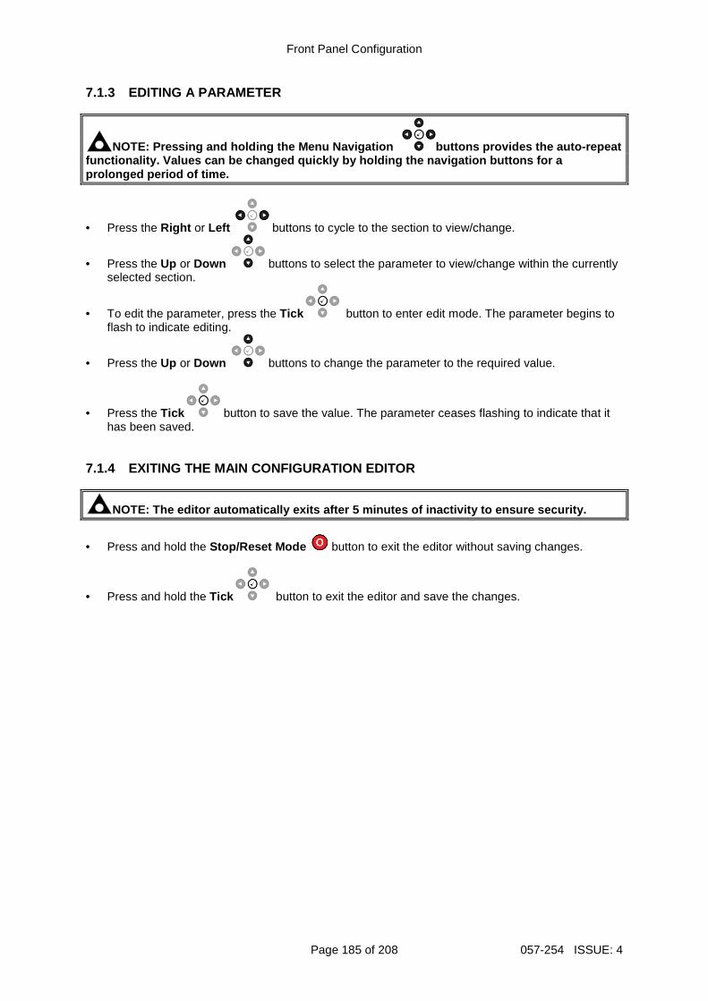
Front Panel Configuration
Page 185 of 208 057-254 ISSUE: 4
7.1.3 EDITING A PARAMETER
NOTE: Pressing and holding the Menu Navigation buttons provides the auto-repeat functionality. Values can be changed quickly by hol ding the navigation buttons for a prolonged period of time.
• Press the Right or Left buttons to cycle to the section to view/change.
• Press the Up or Down buttons to select the parameter to view/change within the currently selected section.
• To edit the parameter, press the Tick button to enter edit mode. The parameter begins to flash to indicate editing.
• Press the Up or Down buttons to change the parameter to the required value.
• Press the Tick button to save the value. The parameter ceases flashing to indicate that it has been saved.
7.1.4 EXITING THE MAIN CONFIGURATION EDITOR
NOTE: The editor automatically exits after 5 minute s of inactivity to ensure security.
• Press and hold the Stop/Reset Mode button to exit the editor without saving changes.
• Press and hold the Tick button to exit the editor and save the changes.
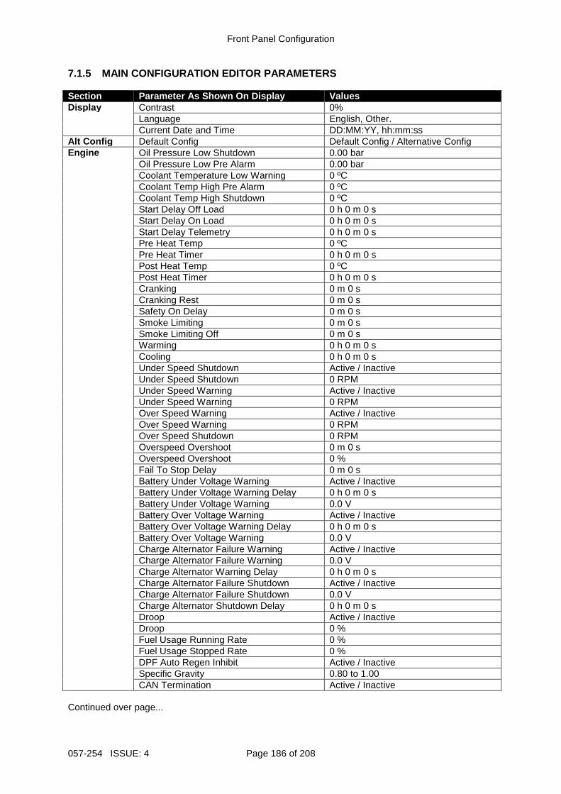
Front Panel Configuration
057-254 ISSUE: 4 Page 186 of 208
7.1.5 MAIN CONFIGURATION EDITOR PARAMETERS Section Parameter As Shown On Display Values Display Contrast 0% Language English, Other. Current Date and Time DD:MM:YY, hh:mm:ss Alt Config Default Config Default Config / Alternative Config Engine Oil Pressure Low Shutdown 0.00 bar Oil Pressure Low Pre Alarm 0.00 bar Coolant Temperature Low Warning 0 ºC Coolant Temp High Pre Alarm 0 ºC Coolant Temp High Shutdown 0 ºC Start Delay Off Load 0 h 0 m 0 s Start Delay On Load 0 h 0 m 0 s Start Delay Telemetry 0 h 0 m 0 s Pre Heat Temp 0 ºC Pre Heat Timer 0 h 0 m 0 s Post Heat Temp 0 ºC Post Heat Timer 0 h 0 m 0 s Cranking 0 m 0 s Cranking Rest 0 m 0 s Safety On Delay 0 m 0 s Smoke Limiting 0 m 0 s Smoke Limiting Off 0 m 0 s Warming 0 h 0 m 0 s Cooling 0 h 0 m 0 s Under Speed Shutdown Active / Inactive Under Speed Shutdown 0 RPM Under Speed Warning Active / Inactive Under Speed Warning 0 RPM Over Speed Warning Active / Inactive Over Speed Warning 0 RPM Over Speed Shutdown 0 RPM Overspeed Overshoot 0 m 0 s Overspeed Overshoot 0 % Fail To Stop Delay 0 m 0 s Battery Under Voltage Warning Active / Inactive Battery Under Voltage Warning Delay 0 h 0 m 0 s Battery Under Voltage Warning 0.0 V Battery Over Voltage Warning Active / Inactive Battery Over Voltage Warning Delay 0 h 0 m 0 s Battery Over Voltage Warning 0.0 V Charge Alternator Failure Warning Active / Inactive Charge Alternator Failure Warning 0.0 V Charge Alternator Warning Delay 0 h 0 m 0 s Charge Alternator Failure Shutdown Active / Inactive Charge Alternator Failure Shutdown 0.0 V Charge Alternator Shutdown Delay 0 h 0 m 0 s Droop Active / Inactive Droop 0 % Fuel Usage Running Rate 0 % Fuel Usage Stopped Rate 0 % DPF Auto Regen Inhibit Active / Inactive Specific Gravity 0.80 to 1.00 CAN Termination Active / Inactive Continued over page...
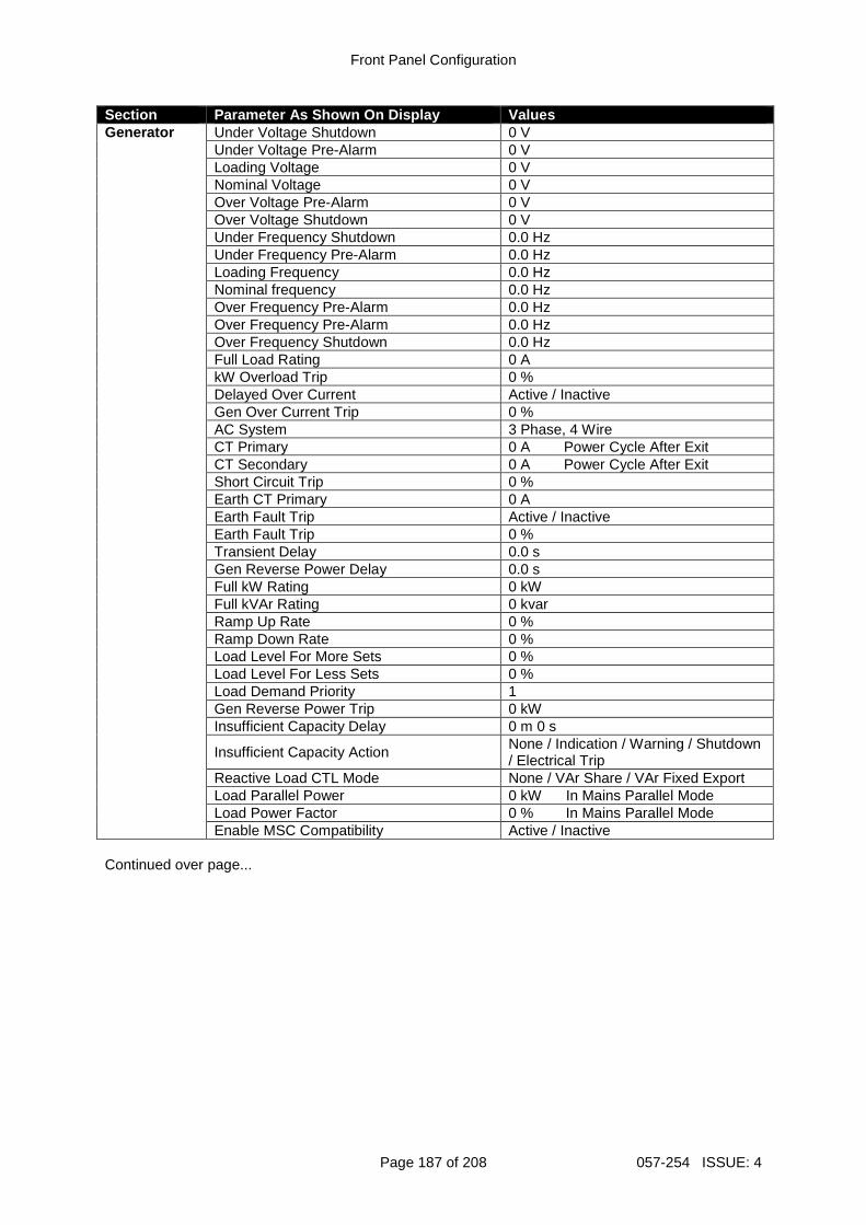
Front Panel Configuration
Page 187 of 208 057-254 ISSUE: 4
Section Parameter As Shown On Display Values Generator Under Voltage Shutdown 0 V Under Voltage Pre-Alarm 0 V Loading Voltage 0 V Nominal Voltage 0 V Over Voltage Pre-Alarm 0 V Over Voltage Shutdown 0 V Under Frequency Shutdown 0.0 Hz Under Frequency Pre-Alarm 0.0 Hz Loading Frequency 0.0 Hz Nominal frequency 0.0 Hz Over Frequency Pre-Alarm 0.0 Hz Over Frequency Pre-Alarm 0.0 Hz Over Frequency Shutdown 0.0 Hz Full Load Rating 0 A kW Overload Trip 0 % Delayed Over Current Active / Inactive Gen Over Current Trip 0 % AC System 3 Phase, 4 Wire CT Primary 0 A Power Cycle After Exit CT Secondary 0 A Power Cycle After Exit Short Circuit Trip 0 % Earth CT Primary 0 A Earth Fault Trip Active / Inactive Earth Fault Trip 0 % Transient Delay 0.0 s Gen Reverse Power Delay 0.0 s Full kW Rating 0 kW Full kVAr Rating 0 kvar Ramp Up Rate 0 % Ramp Down Rate 0 % Load Level For More Sets 0 % Load Level For Less Sets 0 % Load Demand Priority 1 Gen Reverse Power Trip 0 kW Insufficient Capacity Delay 0 m 0 s
Insufficient Capacity Action None / Indication / Warning / Shutdown / Electrical Trip
Reactive Load CTL Mode None / VAr Share / VAr Fixed Export Load Parallel Power 0 kW In Mains Parallel Mode Load Power Factor 0 % In Mains Parallel Mode Enable MSC Compatibility Active / Inactive Continued over page...
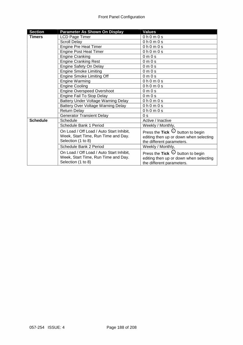
Front Panel Configuration
057-254 ISSUE: 4 Page 188 of 208
Section Parameter As Shown On Display Values Timers LCD Page Timer 0 h 0 m 0 s Scroll Delay 0 h 0 m 0 s Engine Pre Heat Timer 0 h 0 m 0 s Engine Post Heat Timer 0 h 0 m 0 s Engine Cranking 0 m 0 s Engine Cranking Rest 0 m 0 s Engine Safety On Delay 0 m 0 s Engine Smoke Limiting 0 m 0 s Engine Smoke Limiting Off 0 m 0 s Engine Warming 0 h 0 m 0 s Engine Cooling 0 h 0 m 0 s Engine Overspeed Overshoot 0 m 0 s Engine Fail To Stop Delay 0 m 0 s Battery Under Voltage Warning Delay 0 h 0 m 0 s Battery Over Voltage Warning Delay 0 h 0 m 0 s Return Delay 0 h 0 m 0 s Generator Transient Delay 0 s Schedule Schedule Active / Inactive Schedule Bank 1 Period Weekly / Monthly,
On Load / Off Load / Auto Start Inhibit, Week, Start Time, Run Time and Day. Selection (1 to 8)
Press the Tick button to begin editing then up or down when selecting the different parameters.
Schedule Bank 2 Period Weekly / Monthly,
On Load / Off Load / Auto Start Inhibit, Week, Start Time, Run Time and Day. Selection (1 to 8)
Press the Tick button to begin editing then up or down when selecting the different parameters.
Front Panel Configuration
Page 189 of 208 057-254 ISSUE: 4
7.2 ‘RUNNING’ CONFIGURATION EDITOR 7.2.1 ACCESSING THE ‘RUNNING’ CONFIGURATION EDITOR
NOTE: Depending upon module configuration, some par ameters in the ‘Running’ Editor may not be available. For more information refer to DSE publication 057-239 DSE8610 MKII Configuraiton Suite PC Software Manual available from www.deepseaplc.com • The ‘Running’ Configuration Editor is accessible without stopping the engine. All protections
remain active whilst using the ‘‘Running’ Configuration Editor.
• Press and hold the Tick button to access the ‘Running’ Configuration Editor. 7.2.2 ENTERING PIN Even if a module security PIN has been set, the PIN is not requested whilst entering the ‘Running’ Configuration Editor 7.2.3 EDITING A PARAMETER
NOTE: Pressing and holding the Menu Navigation buttons provides the auto-repeat functionality. Values can be changed quickly by hol ding the navigation buttons for a prolonged period of time.
• Press the Right or Left buttons to cycle to the section to view/change.
• Press the Up or Down buttons to select the parameter to view/change within the currently selected section.
• To edit the parameter, press the Tick button to enter edit mode. The parameter begins to flash to indicate editing.
• Press the Up or Down buttons to change the parameter to the required value.
• Press the Tick button to save the value. The parameter ceases flashing to indicate that it has been saved.
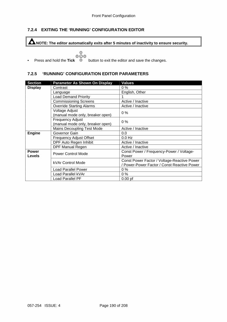
Front Panel Configuration
057-254 ISSUE: 4 Page 190 of 208
7.2.4 EXITING THE ‘RUNNING’ CONFIGURATION EDITOR
NOTE: The editor automatically exits after 5 minute s of inactivity to ensure security.
• Press and hold the Tick button to exit the editor and save the changes. 7.2.5 ‘RUNNING’ CONFIGURATION EDITOR PARAMETERS Section Parameter As Shown On Display Values Display Contrast 0 % Language English, Other Load Demand Priority 1 ) Commissioning Screens Active / Inactive Override Starting Alarms Active / Inactive
Voltage Adjust (manual mode only, breaker open)
0 %
Frequency Adjust (manual mode only, breaker open)
0 %
Mains Decoupling Test Mode Active / Inactive Engine Governor Gain 0.0 Frequency Adjust Offset 0.0 Hz DPF Auto Regen Inhibit Active / Inactive DPF Manual Regen Active / Inactive Power Levels Power Control Mode
Const Power / Frequency-Power / Voltage-Power
kVAr Control Mode Const Power Factor / Voltage-Reactive Power / Power-Power Factor / Const Reactive Power
Load Parallel Power 0 % Load Parallel kVAr 0 % Load Parallel PF 0.00 pf
Commissioning
Page 191 of 208 057-254 ISSUE: 4
8 COMMISIONING 8.1 BASIC CHECKS
NOTE: If Emergency Stop feature is not required, li nk the input to the DC Positive. Before the system is started, it is recommended that the following checks are made: The unit is adequately cooled and all the wiring to the module is of a standard and rating compatible with the system. Check all mechanical parts are fitted correctly and that all electrical connections (including earths) are sound. The unit DC supply is fused and connected to the battery and that it is of the correct polarity. The Emergency Stop input is wired to an external normally closed switch connected to DC positive. To check the start cycle operation, take appropriate measures to prevent the engine from starting (disable the operation of the fuel solenoid). After a visual inspection to ensure it is safe to proceed,
connect the battery supply. Press the Manual Mode button followed by the Start button the unit start sequence commences. The starter engages and operates for the pre-set crank period. After the starter motor has attempted to start the engine for the pre-set number of attempts, the LCD displays Failed to Start. Press the
Stop/Reset Mode button to reset the unit.
Restore the engine to operational status (reconnect the fuel solenoid). Press the Manual Mode
button followed by the Start button. This time the engine should start and the starter motor should disengage automatically. If not then check that the engine is fully operational (fuel available, etc.) and that the fuel solenoid is operating. The engine should now run up to operating speed. If not, and an alarm is present, check the alarm condition for validity, then check input wiring. The engine should continue to run for an indefinite period. It is possible at this time to view the engine and alternator parameters - refer to the ‘Description of Controls’ section of this manual.
Press the Auto Mode button, the engine runs for the pre-set cooling down period, then stop. The generator should stay in the standby mode. If it does not, check that the Remote Start input is not active. Initiate an automatic start by supplying the remote start signal (if configured). The start sequence commences and the engine runs up to operational speed. Once the generator is available the delayed load outputs activate, the Generator accepts the load. If not, check the wiring to the delayed load output contactors. Check the Warming timer has timed out. Remove the remote start signal. The return sequence begins. After the pre-set time, the generator is unloaded. The generator then runs for the pre-set cooling down period, then shutdown into its standby mode. Set the modules internal clock/calendar to ensure correct operation of the scheduler and event logging functions. For details of this procedure see section entitled Front Panel Configuration. If, despite repeated checking of the connections between the controller and the customer’s system, satisfactory operation cannot be achieved, then contact DSE Technical Support Department:
Tel: +44 (0) 1723 890099 Fax: +44 (0) 1723 893303
E-mail: [email protected] Website: www.deepseaplc.com

Commissioning
057-254 ISSUE: 4 Page 192 of 208
8.2 DSE 4 STEPS TO SUCCESSFUL SYNCHRONISING Synchronising and load sharing is often considered to be a complex subject. In fact, it is very simple when broken down into smaller steps. After following the Commissioning section of this manual, the DSE 4 Steps must be followed before any parallel operation is attempted. The following information covers the DSE 4 Steps to Successful Synchronising in full detail and must be completed on all generators in the system. The full video presentation of the 4 Steps is available on the DSE website. www.deepseaplc.com. Registration on the website is required. This is free of charge, along with all other downloads.
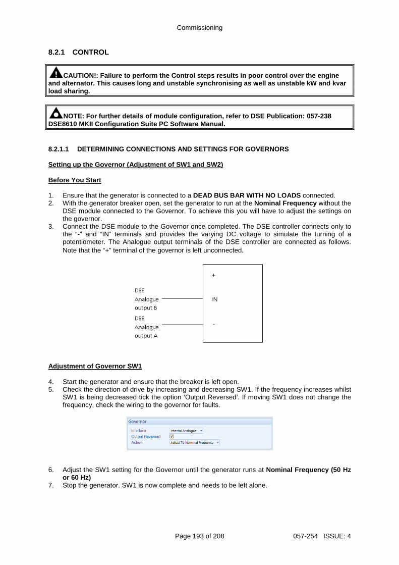
Commissioning
Page 193 of 208 057-254 ISSUE: 4
8.2.1 CONTROL
CAUTION!: Failure to perform the Control steps results in poor control over the engine and alternator. This causes long and unstable synch ronising as well as unstable kW and kvar load sharing.
NOTE: For further details of module configuration, refer to DSE Publication: 057-238 DSE8610 MKII Configuration Suite PC Software Manual . 8.2.1.1 DETERMINING CONNECTIONS AND SETTINGS FOR GOVERNORS Setting up the Governor (Adjustment of SW1 and SW2) Before You Start 1. Ensure that the generator is connected to a DEAD BUS BAR WITH NO LOADS connected. 2. With the generator breaker open, set the generator to run at the Nominal Frequency without the
DSE module connected to the Governor. To achieve this you will have to adjust the settings on the governor.
3. Connect the DSE module to the Governor once completed. The DSE controller connects only to the “-” and “IN” terminals and provides the varying DC voltage to simulate the turning of a potentiometer. The Analogue output terminals of the DSE controller are connected as follows. Note that the “+” terminal of the governor is left unconnected.
Adjustment of Governor SW1 4. Start the generator and ensure that the breaker is left open. 5. Check the direction of drive by increasing and decreasing SW1. If the frequency increases whilst
SW1 is being decreased tick the option ‘Output Reversed’. If moving SW1 does not change the frequency, check the wiring to the governor for faults.
6. Adjust the SW1 setting for the Governor until the generator runs at Nominal Frequency (50 Hz
or 60 Hz) 7. Stop the generator. SW1 is now complete and needs to be left alone.
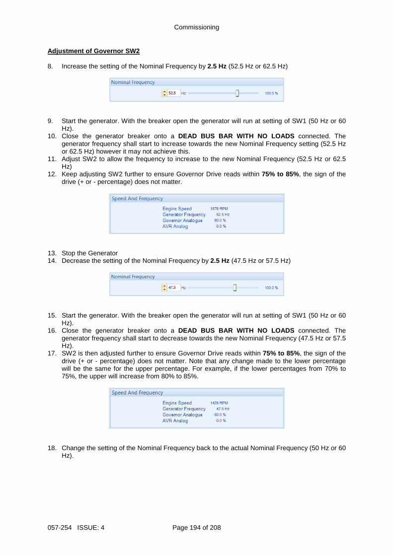
Commissioning
057-254 ISSUE: 4 Page 194 of 208
Adjustment of Governor SW2 8. Increase the setting of the Nominal Frequency by 2.5 Hz (52.5 Hz or 62.5 Hz)
9. Start the generator. With the breaker open the generator will run at setting of SW1 (50 Hz or 60 Hz).
10. Close the generator breaker onto a DEAD BUS BAR WITH NO LOADS connected. The generator frequency shall start to increase towards the new Nominal Frequency setting (52.5 Hz or 62.5 Hz) however it may not achieve this.
11. Adjust SW2 to allow the frequency to increase to the new Nominal Frequency (52.5 Hz or 62.5 Hz)
12. Keep adjusting SW2 further to ensure Governor Drive reads within 75% to 85% , the sign of the drive (+ or - percentage) does not matter.
13. Stop the Generator 14. Decrease the setting of the Nominal Frequency by 2.5 Hz (47.5 Hz or 57.5 Hz)
15. Start the generator. With the breaker open the generator will run at setting of SW1 (50 Hz or 60
Hz). 16. Close the generator breaker onto a DEAD BUS BAR WITH NO LOADS connected. The
generator frequency shall start to decrease towards the new Nominal Frequency (47.5 Hz or 57.5 Hz).
17. SW2 is then adjusted further to ensure Governor Drive reads within 75% to 85% , the sign of the drive (+ or - percentage) does not matter. Note that any change made to the lower percentage will be the same for the upper percentage. For example, if the lower percentages from 70% to 75%, the upper will increase from 80% to 85%.
18. Change the setting of the Nominal Frequency back to the actual Nominal Frequency (50 Hz or 60
Hz).
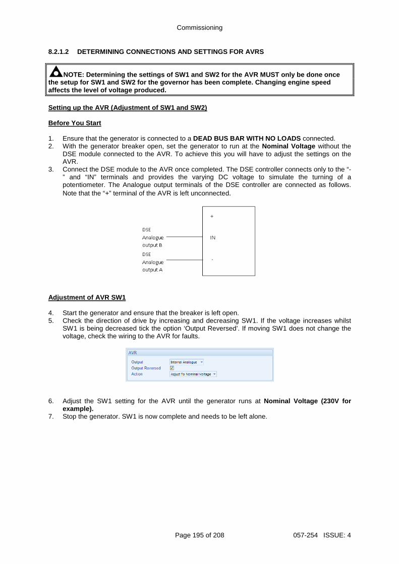
Commissioning
Page 195 of 208 057-254 ISSUE: 4
8.2.1.2 DETERMINING CONNECTIONS AND SETTINGS FOR AVRS
NOTE: Determining the settings of SW1 and SW2 for t he AVR MUST only be done once the setup for SW1 and SW2 for the governor has been complete. Changing engine speed affects the level of voltage produced. Setting up the AVR (Adjustment of SW1 and SW2) Before You Start 1. Ensure that the generator is connected to a DEAD BUS BAR WITH NO LOADS connected. 2. With the generator breaker open, set the generator to run at the Nominal Voltage without the
DSE module connected to the AVR. To achieve this you will have to adjust the settings on the AVR.
3. Connect the DSE module to the AVR once completed. The DSE controller connects only to the “-” and “IN” terminals and provides the varying DC voltage to simulate the turning of a potentiometer. The Analogue output terminals of the DSE controller are connected as follows. Note that the “+” terminal of the AVR is left unconnected.
Adjustment of AVR SW1 4. Start the generator and ensure that the breaker is left open. 5. Check the direction of drive by increasing and decreasing SW1. If the voltage increases whilst
SW1 is being decreased tick the option ‘Output Reversed’. If moving SW1 does not change the voltage, check the wiring to the AVR for faults.
6. Adjust the SW1 setting for the AVR until the generator runs at Nominal Voltage (230V for
example). 7. Stop the generator. SW1 is now complete and needs to be left alone.
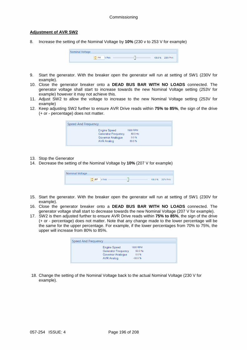
Commissioning
057-254 ISSUE: 4 Page 196 of 208
Adjustment of AVR SW2 8. Increase the setting of the Nominal Voltage by 10% (230 v to 253 V for example)
9. Start the generator. With the breaker open the generator will run at setting of SW1 (230V for
example). 10. Close the generator breaker onto a DEAD BUS BAR WITH NO LOADS connected. The
generator voltage shall start to increase towards the new Nominal Voltage setting (253V for example) however it may not achieve this.
11. Adjust SW2 to allow the voltage to increase to the new Nominal Voltage setting (253V for example)
12. Keep adjusting SW2 further to ensure AVR Drive reads within 75% to 85% , the sign of the drive (+ or - percentage) does not matter.
13. Stop the Generator 14. Decrease the setting of the Nominal Voltage by 10% (207 V for example)
15. Start the generator. With the breaker open the generator will run at setting of SW1 (230V for
example). 16. Close the generator breaker onto a DEAD BUS BAR WITH NO LOADS connected. The
generator voltage shall start to decrease towards the new Nominal Voltage (207 V for example). 17. SW2 is then adjusted further to ensure AVR Drive reads within 75% to 85% , the sign of the drive
(+ or - percentage) does not matter. Note that any change made to the lower percentage will be the same for the upper percentage. For example, if the lower percentages from 70% to 75%, the upper will increase from 80% to 85%.
18. Change the setting of the Nominal Voltage back to the actual Nominal Voltage (230 V for
example).
Commissioning
Page 197 of 208 057-254 ISSUE: 4
8.2.2 METERING
CAUTION!: Failure to perform the Metering steps res ults in incorrect power factor and kW calculations leading to problems with kW and kvar l oad sharing if not corrected.
WARNING!: Do not disconnect the CT wires from the D SE module when the CTs are carrying current. Disconnection open circuits the s econdary of the CT’s and dangerous voltages may then develop. Always ensure the CTs ar e not carrying current and the CTs are short circuit connected before making or breaking c onnections to the module. 8.2.2.1 CTS ON THE RIGHT PHASE Check to ensure that the CTs on L1, L2 & L3 are connected to their respective connection on the DSE module. This is tested by loading the generator with a purely resistive load (around 10% of the generator’s size) across the three phases. If the CTs are wired correctly to the DSE module, it displays unity power factor (1.0 pf) across all three phases. If unity power factor is not displayed the CTs have been wired to the wrong phases on the DSE module. 8.2.2.2 CTS IN THE RIGHT DIRECTION
NOTE: Checking that the CTs are on the right phase MUST be completed prior to checking if the CTs are in the correct direction. CTs on the wrong phase also cause negative kWs. Check to ensure that the CTs on L1, L2 & L3 have been mounted for the correct orientation for current flow and that the S1 and S2 have not been swapped over. This is tested by loading the generator with a purely resistive load (around 10% of the generator’s size) across the three phases. If the CTs’ S1 and S2 are wired to correctly to the DSE module, it displays positive kW. If negative kWs is displayed the CTs’ S1 and S2 have been swapped around.
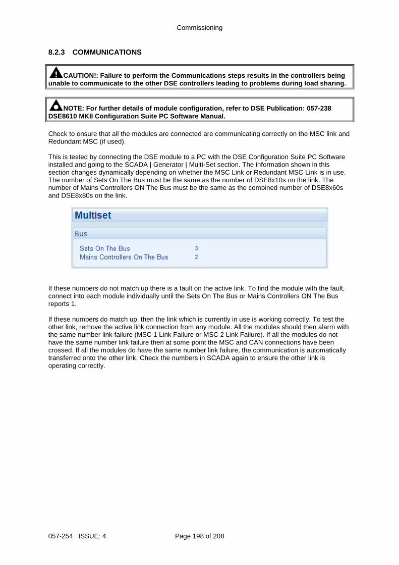
Commissioning
057-254 ISSUE: 4 Page 198 of 208
8.2.3 COMMUNICATIONS
CAUTION!: Failure to perform the Communications ste ps results in the controllers being unable to communicate to the other DSE controllers leading to problems during load sharing.
NOTE: For further details of module configuration, refer to DSE Publication: 057-238 DSE8610 MKII Configuration Suite PC Software Manual . Check to ensure that all the modules are connected are communicating correctly on the MSC link and Redundant MSC (if used). This is tested by connecting the DSE module to a PC with the DSE Configuration Suite PC Software installed and going to the SCADA | Generator | Multi-Set section. The information shown in this section changes dynamically depending on whether the MSC Link or Redundant MSC Link is in use. The number of Sets On The Bus must be the same as the number of DSE8x10s on the link. The number of Mains Controllers ON The Bus must be the same as the combined number of DSE8x60s and DSE8x80s on the link.
If these numbers do not match up there is a fault on the active link. To find the module with the fault, connect into each module individually until the Sets On The Bus or Mains Controllers ON The Bus reports 1. If these numbers do match up, then the link which is currently in use is working correctly. To test the other link, remove the active link connection from any module. All the modules should then alarm with the same number link failure (MSC 1 Link Failure or MSC 2 Link Failure). If all the modules do not have the same number link failure then at some point the MSC and CAN connections have been crossed. If all the modules do have the same number link failure, the communication is automatically transferred onto the other link. Check the numbers in SCADA again to ensure the other link is operating correctly.
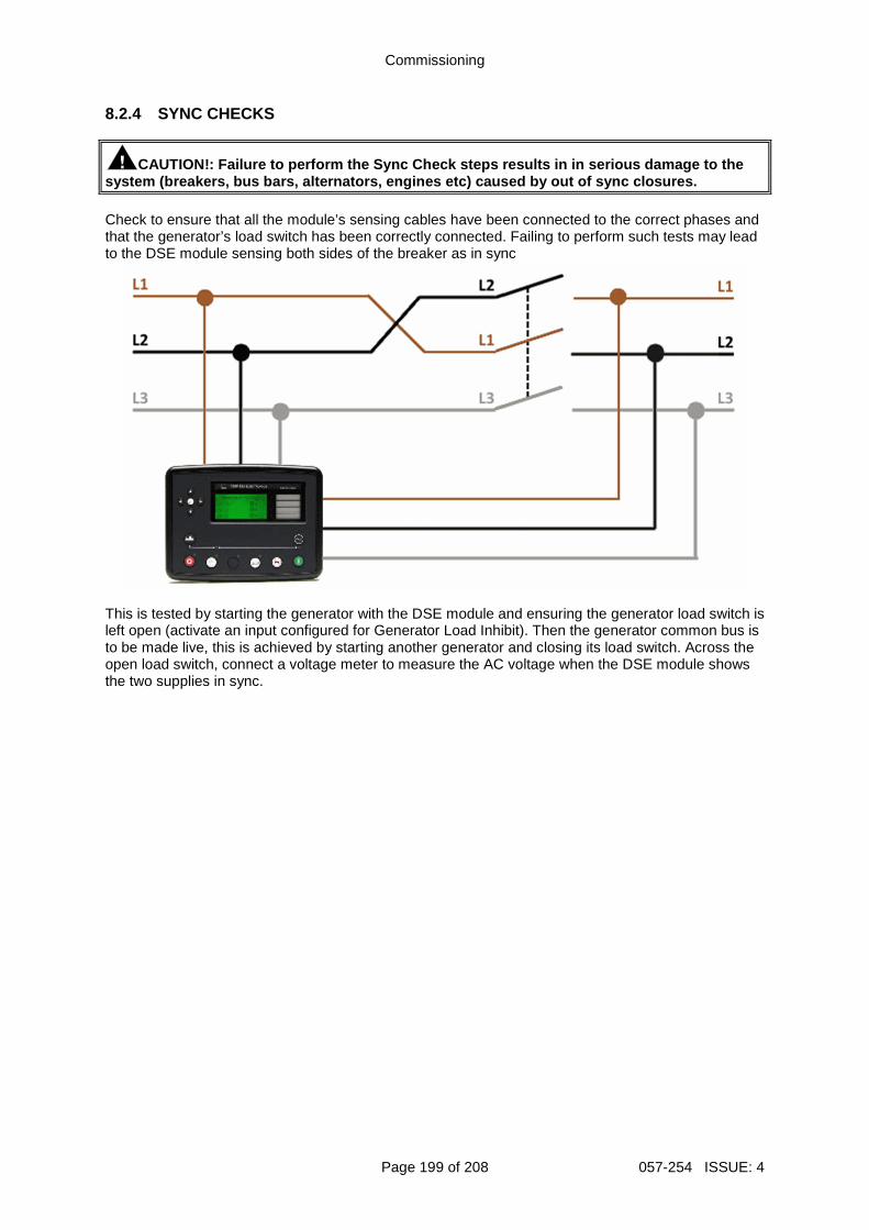
Commissioning
Page 199 of 208 057-254 ISSUE: 4
8.2.4 SYNC CHECKS
CAUTION!: Failure to perform the Sync Check steps r esults in in serious damage to the system (breakers, bus bars, alternators, engines et c) caused by out of sync closures. Check to ensure that all the module’s sensing cables have been connected to the correct phases and that the generator’s load switch has been correctly connected. Failing to perform such tests may lead to the DSE module sensing both sides of the breaker as in sync
This is tested by starting the generator with the DSE module and ensuring the generator load switch is left open (activate an input configured for Generator Load Inhibit). Then the generator common bus is to be made live, this is achieved by starting another generator and closing its load switch. Across the open load switch, connect a voltage meter to measure the AC voltage when the DSE module shows the two supplies in sync.
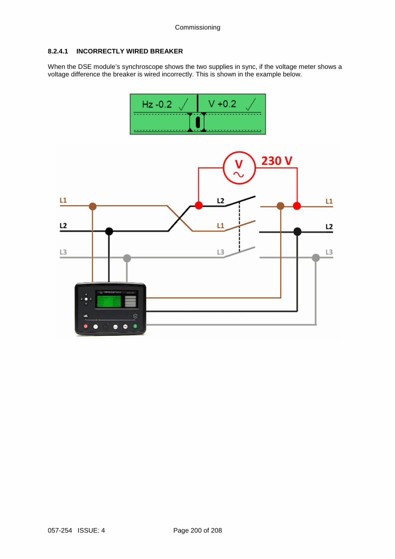
Commissioning
057-254 ISSUE: 4 Page 200 of 208
8.2.4.1 INCORRECTLY WIRED BREAKER When the DSE module’s synchroscope shows the two supplies in sync, if the voltage meter shows a voltage difference the breaker is wired incorrectly. This is shown in the example below.
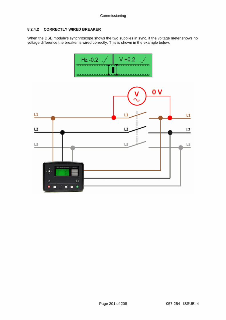
Commissioning
Page 201 of 208 057-254 ISSUE: 4
8.2.4.2 CORRECTLY WIRED BREAKER When the DSE module’s synchroscope shows the two supplies in sync, if the voltage meter shows no voltage difference the breaker is wired correctly. This is shown in the example below.
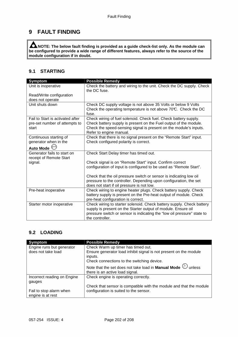
Fault Finding
057-254 ISSUE: 4 Page 202 of 208
9 FAULT FINDING
NOTE: The below fault finding is provided as a guid e check-list only. As the module can be configured to provide a wide range of different features, always refer to the source of the module configuration if in doubt. 9.1 STARTING Symptom Possible Remedy Unit is inoperative Read/Write configuration does not operate
Check the battery and wiring to the unit. Check the DC supply. Check the DC fuse.
Unit shuts down Check DC supply voltage is not above 35 Volts or below 9 Volts Check the operating temperature is not above 70°C. Check the DC fuse.
Fail to Start is activated after pre-set number of attempts to start
Check wiring of fuel solenoid. Check fuel. Check battery supply. Check battery supply is present on the Fuel output of the module. Check the speed-sensing signal is present on the module’s inputs. Refer to engine manual.
Continuous starting of generator when in the
Auto Mode
Check that there is no signal present on the “Remote Start” input. Check configured polarity is correct.
Generator fails to start on receipt of Remote Start signal.
Check Start Delay timer has timed out. Check signal is on “Remote Start” input. Confirm correct configuration of input is configured to be used as “Remote Start”. Check that the oil pressure switch or sensor is indicating low oil pressure to the controller. Depending upon configuration, the set does not start if oil pressure is not low.
Pre-heat inoperative Check wiring to engine heater plugs. Check battery supply. Check battery supply is present on the Pre-heat output of module. Check pre-heat configuration is correct.
Starter motor inoperative Check wiring to starter solenoid. Check battery supply. Check battery supply is present on the Starter output of module. Ensure oil pressure switch or sensor is indicating the “low oil pressure” state to the controller.
9.2 LOADING Symptom Possible Remedy Engine runs but generator does not take load
Check Warm up timer has timed out. Ensure generator load inhibit signal is not present on the module inputs. Check connections to the switching device.
Note that the set does not take load in Manual Mode unless there is an active load signal.
Incorrect reading on Engine gauges Fail to stop alarm when engine is at rest
Check engine is operating correctly. Check that sensor is compatible with the module and that the module configuration is suited to the sensor.
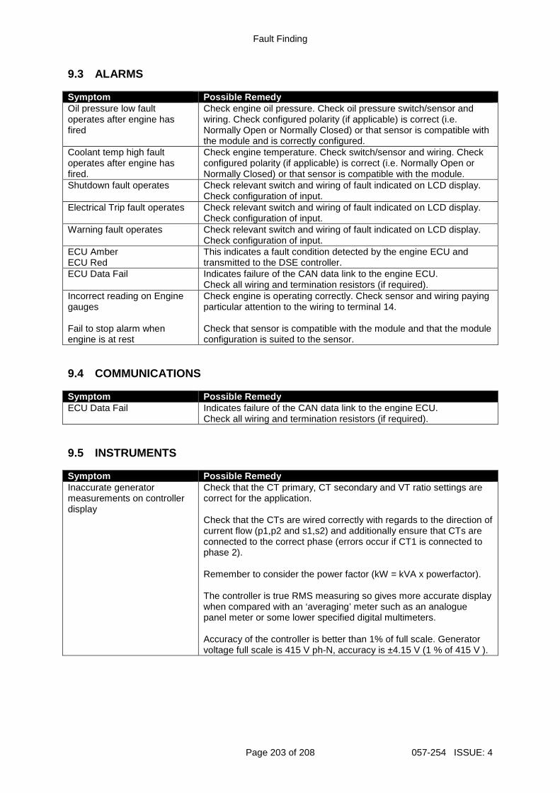
Fault Finding
Page 203 of 208 057-254 ISSUE: 4
9.3 ALARMS Symptom Possible Remedy Oil pressure low fault operates after engine has fired
Check engine oil pressure. Check oil pressure switch/sensor and wiring. Check configured polarity (if applicable) is correct (i.e. Normally Open or Normally Closed) or that sensor is compatible with the module and is correctly configured.
Coolant temp high fault operates after engine has fired.
Check engine temperature. Check switch/sensor and wiring. Check configured polarity (if applicable) is correct (i.e. Normally Open or Normally Closed) or that sensor is compatible with the module.
Shutdown fault operates Check relevant switch and wiring of fault indicated on LCD display. Check configuration of input.
Electrical Trip fault operates Check relevant switch and wiring of fault indicated on LCD display. Check configuration of input.
Warning fault operates Check relevant switch and wiring of fault indicated on LCD display. Check configuration of input.
ECU Amber ECU Red
This indicates a fault condition detected by the engine ECU and transmitted to the DSE controller.
ECU Data Fail Indicates failure of the CAN data link to the engine ECU. Check all wiring and termination resistors (if required).
Incorrect reading on Engine gauges Fail to stop alarm when engine is at rest
Check engine is operating correctly. Check sensor and wiring paying particular attention to the wiring to terminal 14. Check that sensor is compatible with the module and that the module configuration is suited to the sensor.
9.4 COMMUNICATIONS Symptom Possible Remedy ECU Data Fail Indicates failure of the CAN data link to the engine ECU.
Check all wiring and termination resistors (if required). 9.5 INSTRUMENTS Symptom Possible Remedy Inaccurate generator measurements on controller display
Check that the CT primary, CT secondary and VT ratio settings are correct for the application. Check that the CTs are wired correctly with regards to the direction of current flow (p1,p2 and s1,s2) and additionally ensure that CTs are connected to the correct phase (errors occur if CT1 is connected to phase 2). Remember to consider the power factor (kW = kVA x powerfactor). The controller is true RMS measuring so gives more accurate display when compared with an ‘averaging’ meter such as an analogue panel meter or some lower specified digital multimeters. Accuracy of the controller is better than 1% of full scale. Generator voltage full scale is 415 V ph-N, accuracy is ±4.15 V (1 % of 415 V ).
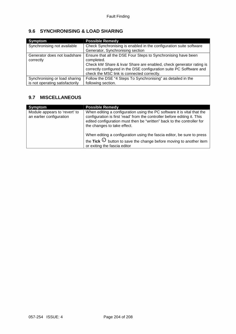
Fault Finding
057-254 ISSUE: 4 Page 204 of 208
9.6 SYNCHRONISING & LOAD SHARING Symptom Possible Remedy Synchronising not available Check Synchronising is enabled in the configuration suite software
Generator, Synchronising section Generator does not loadshare correctly
Ensure that all the DSE Four Steps to Synchronising have been completed. Check kW Share & kvar Share are enabled, check generator rating is correctly configured in the DSE configuration suite PC Sofftware and check the MSC link is connected correctly.
Synchronising or load sharing is not operating satisfactorily
Follow the DSE “4 Steps To Synchronising” as detailed in the following section.
9.7 MISCELLANEOUS Symptom Possible Remedy Module appears to ‘revert’ to an earlier configuration
When editing a configuration using the PC software it is vital that the configuration is first ‘read’ from the controller before editing it. This edited configuration must then be “written” back to the controller for the changes to take effect. When editing a configuration using the fascia editor, be sure to press
the Tick button to save the change before moving to another item or exiting the fascia editor
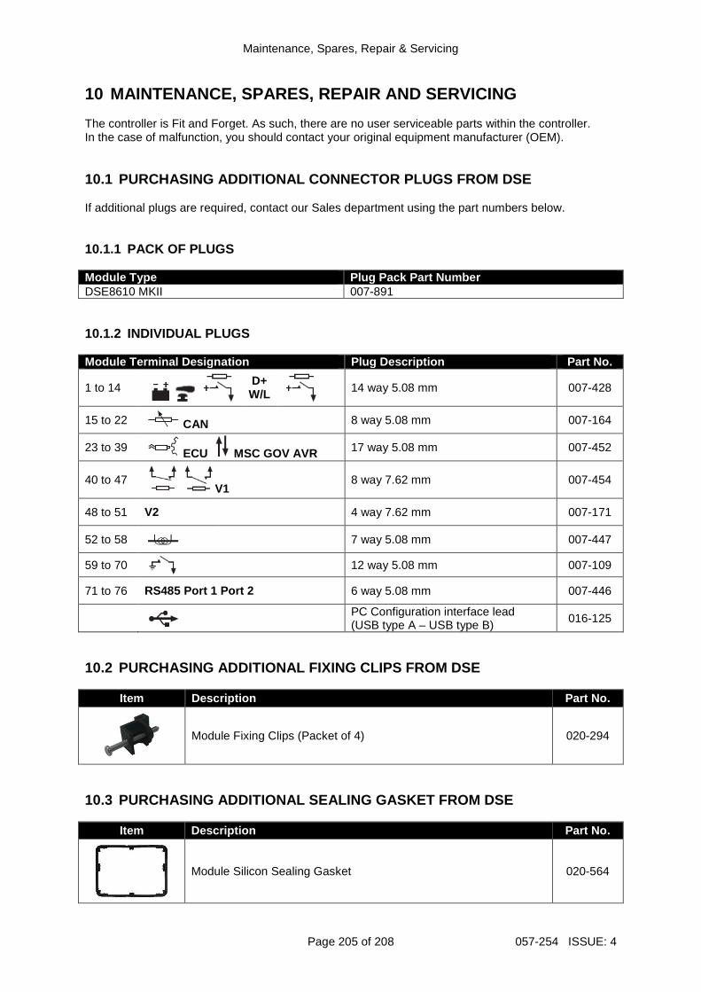
Maintenance, Spares, Repair & Servicing
Page 205 of 208 057-254 ISSUE: 4
10 MAINTENANCE, SPARES, REPAIR AND SERVICING The controller is Fit and Forget. As such, there are no user serviceable parts within the controller. In the case of malfunction, you should contact your original equipment manufacturer (OEM). 10.1 PURCHASING ADDITIONAL CONNECTOR PLUGS FROM DSE If additional plugs are required, contact our Sales department using the part numbers below. 10.1.1 PACK OF PLUGS Module Type Plug Pack Part Number DSE8610 MKII 007-891 10.1.2 INDIVIDUAL PLUGS Module Terminal Designation Plug Description Part No.
1 to 14
D+ W/L
14 way 5.08 mm 007-428
15 to 22 CAN 8 way 5.08 mm 007-164
23 to 39 ECU MSC GOV AVR 17 way 5.08 mm 007-452
40 to 47 V1
8 way 7.62 mm 007-454
48 to 51 V2 4 way 7.62 mm 007-171
52 to 58 7 way 5.08 mm 007-447
59 to 70
12 way 5.08 mm 007-109
71 to 76 RS485 Port 1 Port 2 6 way 5.08 mm 007-446
PC Configuration interface lead (USB type A – USB type B)
016-125
10.2 PURCHASING ADDITIONAL FIXING CLIPS FROM DSE
Item Description Part No.
Module Fixing Clips (Packet of 4) 020-294
10.3 PURCHASING ADDITIONAL SEALING GASKET FROM DSE
Item Description Part No.
Module Silicon Sealing Gasket 020-564
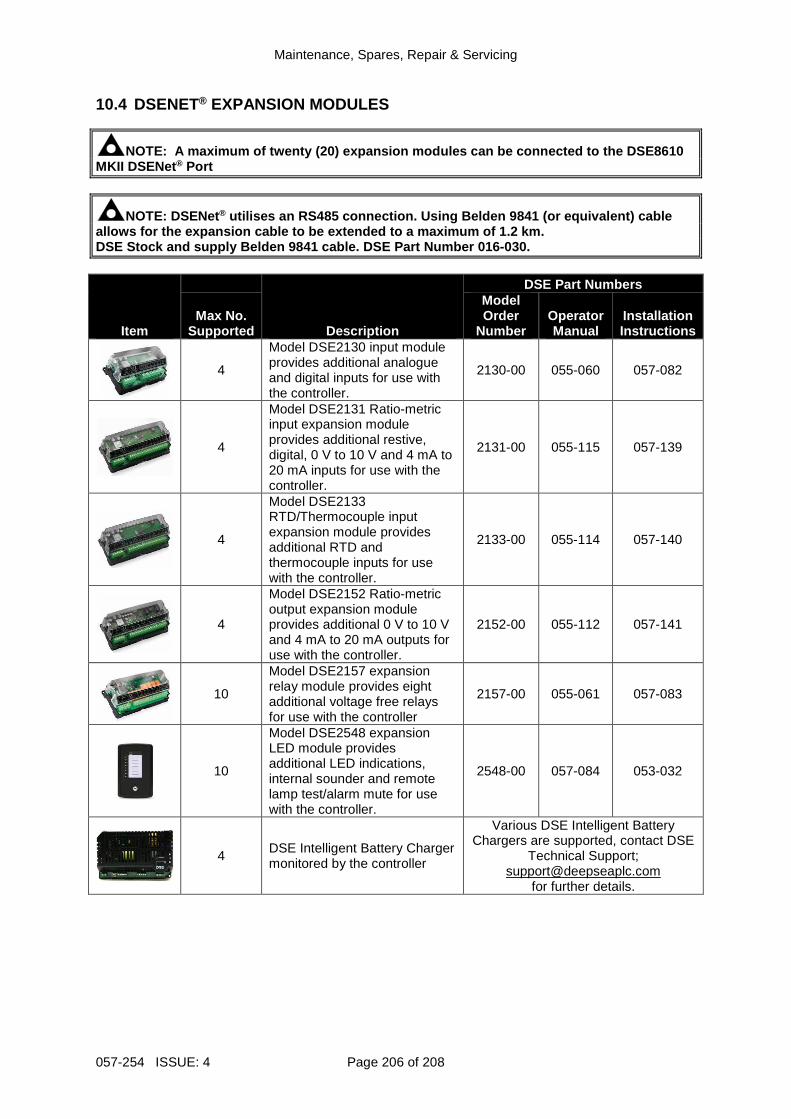
Maintenance, Spares, Repair & Servicing
057-254 ISSUE: 4 Page 206 of 208
10.4 DSENET® EXPANSION MODULES
NOTE: A maximum of twenty (20) expansion modules c an be connected to the DSE8610 MKII DSENet ® Port
NOTE: DSENet ® utilises an RS485 connection. Using Belden 9841 (o r equivalent) cable allows for the expansion cable to be extended to a maximum of 1.2 km. DSE Stock and supply Belden 9841 cable. DSE Part Nu mber 016-030.
Item
Description
DSE Part Numbers
Max No. Supported
Model Order
Number Operator Manual
Installation Instructions
4
Model DSE2130 input module provides additional analogue and digital inputs for use with the controller.
2130-00 055-060 057-082
4
Model DSE2131 Ratio-metric input expansion module provides additional restive, digital, 0 V to 10 V and 4 mA to 20 mA inputs for use with the controller.
2131-00 055-115 057-139
4
Model DSE2133 RTD/Thermocouple input expansion module provides additional RTD and thermocouple inputs for use with the controller.
2133-00 055-114 057-140
4
Model DSE2152 Ratio-metric output expansion module provides additional 0 V to 10 V and 4 mA to 20 mA outputs for use with the controller.
2152-00 055-112 057-141
10
Model DSE2157 expansion relay module provides eight additional voltage free relays for use with the controller
2157-00 055-061 057-083
10
Model DSE2548 expansion LED module provides additional LED indications, internal sounder and remote lamp test/alarm mute for use with the controller.
2548-00 057-084 053-032
4 DSE Intelligent Battery Charger monitored by the controller
Various DSE Intelligent Battery Chargers are supported, contact DSE
Technical Support; [email protected]
for further details.
Maintenance, Spares, Repair & Servicing
Page 207 of 208 057-254 ISSUE: 4
11 WARRANTY DSE Provides limited warranty to the equipment purchaser at the point of sale. For full details of any applicable warranty, refer to the original equipment supplier (OEM)
12 DISPOSAL 12.1 WEEE (WASTE ELECTRICAL AND ELECTRONIC EQUIPMEN T) If you use electrical and electronic equipment you must store, collect, treat, recycle and dispose of WEEE separately from your other waste

This Page is Intentionally Blank