Embed Size (px)
Citation preview

057-260 ISSUE: 3
DEEP SEA ELECTRONICS PLC DSE4510 MKII & DSE4520 MKII
Operator Manual
Document Number: 057-260
Author: Ashley Senior

DSE4510 MKII & DSE4520 MKII Operator Manual
057-260 ISSUE: 3 Page 2 of 116
Deep Sea Electronics Plc Highfield House Hunmanby North Yorkshire YO14 0PH ENGLAND Sales Tel: +44 (0) 1723 890099 Sales Fax: +44 (0) 1723 893303 E-mail: [email protected] Website: www.deepseaplc.com DSE4510 MKII & DSE4520 MKII Operator Manual © Deep Sea Electronics Plc All rights reserved. No part of this publication may be reproduced in any material form (including photocopying or storing in any medium by electronic means or other) without the written permission of the copyright holder except in accordance with the provisions of the Copyright, Designs and Patents Act 1988. Applications for the copyright holder’s written permission to reproduce any part of this publication must be addressed to Deep Sea Electronics Plc at the address above. The DSE logo and the names DSEGenset®, DSEAts® and DSEPower® are UK registered trademarks of Deep Sea Electronics PLC. Any reference to trademarked product names used within this publication is owned by their respective companies. Deep Sea Electronics Plc reserves the right to change the contents of this document without prior notice. Amendments Since Last Publication Amd. No. Comments
1 Initial Release 1.1 Changed output source 98 to reserved.
2 Update to Bibliography, J1939-75, Adding External Sounder, Module Display, Configurable CAN Instrumentation and Front Panel Editor
3 Update to Analogue Input A Specification, Alarm Icons and Front Panel Edtior.

DSE4510 MKII & DSE4520 MKII Operator Manual
Page 3 of 116 057-260 ISSUE: 3
TABLE OF CONTENTS
Section Page 1 INTRODUCTION .................................................................................................. 6
1.1 CLARIFICATION OF NOTATION ......................... ................................................................... 7
1.2 GLOSSARY OF TERMS ................................. ......................................................................... 7
1.3 BIBLIOGRAPHY ...................................... ................................................................................ 9
1.3.1 INSTALLATION INSTRUCTIONS ..................................................................................... 9
1.3.2 MANUALS ......................................................................................................................... 9
1.3.3 TRAINING GUIDES ........................................................................................................ 10
1.3.4 THIRD PARTY DOCUMENTS ........................................................................................ 10
2 SPECIFICATION ................................................................................................ 11
2.1 OPERATING TEMPERATURE ............................. ................................................................. 11
2.1.1 OPTIONAL SCREEN HEATER OPERATION ................................................................ 11
2.2 REQUIREMENTS FOR UL .................................................................................................... 11
2.3 TERMINAL SPECIFICATION ............................ .................................................................... 12
2.4 POWER SUPPLY REQUIREMENTS ..................................................................................... 12
2.4.1 MODULE SUPPLY INSTRUMENTATION DISPLAY ...................................................... 12
2.5 VOLTAGE & FREQUENCY SENSING ....................... ........................................................... 13
2.6 CURRENT SENSING ............................................................................................................. 13
2.6.1 VA RATING OF THE CTS ............................................................................................... 14
2.6.2 CT POLARITY ................................................................................................................. 15
2.6.3 CT PHASING ................................................................................................................... 15
2.6.4 CT CLASS ....................................................................................................................... 15
2.7 INPUTS ................................................................................................................................... 16
2.7.1 DIGITAL INPUTS ............................................................................................................ 16
2.7.2 ANALOGUE INPUTS ...................................................................................................... 17
2.7.2.1 ANALOGUE INPUT A .............................................................................................. 17
2.7.2.2 ANALOGUE INPUT B .............................................................................................. 18
2.7.2.3 ANALOGUE INPUT C .............................................................................................. 18
2.7.3 CHARGE FAIL INPUT ..................................................................................................... 18
2.8 OUTPUTS ............................................................................................................................... 19
2.8.1 DC OUTPUTS A & B (FUEL & START) .......................................................................... 19
2.8.2 DC OUTPUTS C, D, E & F .............................................................................................. 19
2.9 COMMUNICATION PORTS ................................................................................................... 19
2.10 COMMUNICATION PORT USAGE .......................... .......................................................... 20
2.10.1 USB SLAVE PORT (PC CONFIGURATION) .................................................................. 20
2.10.2 CAN PORT (J1939) ......................................................................................................... 21
2.10.2.1 J1939-75 .................................................................................................................. 22
2.11 ADDING AN EXTERNAL SOUNDER ........................ ........................................................ 27
2.12 ACCUMULATED INSTRUMENTATION ....................... ..................................................... 28
2.13 DIMENSIONS AND MOUNTING ........................................................................................ 28
2.13.1 DIMENSIONS .................................................................................................................. 28
2.13.2 PANEL CUTOUT ............................................................................................................. 28
2.13.3 WEIGHT .......................................................................................................................... 28
2.13.4 FIXING CLIPS ................................................................................................................. 29
2.13.5 OPTIONAL SILICON SEALING GASKET ...................................................................... 30
2.14 APPLICABLE STANDARDS .............................. ............................................................... 31
2.14.1 ENCLOSURE CLASSIFICATIONS ................................................................................. 33
2.14.1.1 IP CLASSIFICATIONS ............................................................................................. 33
2.14.1.2 NEMA CLASSIFICATIONS ...................................................................................... 33
3 INSTALLATION ...................................... ........................................................... 34
3.1 USER CONNECTIONS .......................................................................................................... 34
3.2 CONNECTION DESCRIPTIONS ........................................................................................... 35
3.2.1 DC SUPPLY, DC OUTPUTS & CHARGE FAIL INPUT .................................................. 35
3.2.2 ANALOGUE SENSOR INPUTS ...................................................................................... 36
3.2.3 CONFIGURABLE DIGITAL INPUTS & CAN ................................................................... 37

DSE4510 MKII & DSE4520 MKII Operator Manual
057-260 ISSUE: 3 Page 4 of 116
3.2.4 GENERATOR & MAINS VOLTAGE & FREQUENCY SENSING ................................... 38
3.2.5 CURRENT TRANSFORMERS ........................................................................................ 39
3.2.5.1 CT CONNECTIONS ................................................................................................. 39
3.2.6 USB SLAVE (PC CONFIGURATION) CONNECTOR .................................................... 40
3.3 TYPICAL WIRING DIAGRAM ............................ .................................................................... 41
3.3.1 DSE4510 MKII TYPICAL WIRING DIAGRAM (3 PHASE 4 WIRE) ................................ 42
3.3.2 DSE4520 MKII TYPICAL WIRING DIAGRAM (3 PHASE 4 WIRE) ................................ 43
3.3.3 EARTH SYSTEMS .......................................................................................................... 44
3.3.3.1 NEGATIVE EARTH .................................................................................................. 44
3.3.3.2 POSITIVE EARTH ................................................................................................... 44
3.3.3.3 FLOATING EARTH .................................................................................................. 44
3.4 ALTERNATE TOPOLOGY WIRING DIAGRAMS ................ ................................................. 45
3.4.1 GENERATOR .................................................................................................................. 45
3.4.2 MAINS (DSE4520 MKII ONLY) ....................................................................................... 46
4 DESCRIPTION OF CONTROLS ........................................................................ 47
4.1 CONTROL PUSH BUTTONS .............................. .................................................................. 48
4.2 MODULE DISPLAY .................................... ............................................................................ 50
4.2.1 INSTRUMENTATION ICONS ......................................................................................... 51
4.2.2 ACTIVE CONFIGURATION ............................................................................................ 53
4.2.3 FRONT PANEL EDITOR (FPE) / AUTO RUN ICON ...................................................... 53
4.2.4 MODE ICON .................................................................................................................... 53
4.2.5 LOAD SWITCHING ICON ............................................................................................... 54
4.2.6 SPLASH SCREEN .......................................................................................................... 54
4.2.7 BACKLIGHT .................................................................................................................... 55
4.2.8 ALARM ICONS (PROTECTIONS) .................................................................................. 56
4.2.8.1 WARNING ALARM ICONS ...................................................................................... 57
4.2.8.2 ELECTRICAL TRIP ALARM ICONS ........................................................................ 59
4.2.8.3 SHUTDOWN ALARM ICONS .................................................................................. 60
4.3 VIEWING THE INSTRUMENT PAGES .................................................................................. 62
4.3.1 NAVIGATION MENU ....................................................................................................... 62
4.3.1.1 NAVIGATION MENU ICONS ................................................................................... 63
4.3.2 GENERAL NAVIGATION ................................................................................................ 64
4.3.3 HOME .............................................................................................................................. 65
4.3.3.1 VOLTAGE INSTRUMENTATION ............................................................................ 65
4.3.3.2 ENGINE TIER 4 INSTRUMENTATION ................................................................... 65
4.3.4 GENERATOR .................................................................................................................. 66
4.3.5 MAINS (DSE4520 MKII ONLY) ....................................................................................... 66
4.3.6 LOAD ............................................................................................................................... 67
4.3.7 ENGINE ........................................................................................................................... 68
4.3.8 CONFIGURABLE CAN INSTRUNMENTS ...................................................................... 69
4.3.9 INFO ................................................................................................................................ 69
4.3.10 ENGINE DTC (ECU ALARMS) ....................................................................................... 70
4.3.10.1 VIEWING ACTIVE ENGINE DTC ............................................................................ 70
4.3.11 EVENT LOG .................................................................................................................... 72
4.3.11.1 VIEWING THE EVENT LOG .................................................................................... 72
4.3.12 ENGINE TIER 4 INFORMATION .................................................................................... 73
4.3.12.1 ENGINE TIER 4 LAMPS .......................................................................................... 74
4.3.12.2 DPF INHIBIT CONTROL .......................................................................................... 75
5 OPERATION ...................................................................................................... 76
5.1 QUICKSTART GUIDE .................................. .......................................................................... 76
5.1.1 STARTING THE ENGINE ............................................................................................... 76
5.1.2 STOPPING THE ENGINE ............................................................................................... 77
5.2 STOP/RESET MODE ............................................................................................................. 78
5.3 AUTOMATIC MODE .................................... .......................................................................... 79
5.3.1 WAITING IN AUTO MODE .............................................................................................. 79
5.3.2 STARTING SEQUENCE ................................................................................................. 80
5.3.3 ENGINE RUNNING ......................................................................................................... 81
5.3.4 STOPPING SEQUENCE ................................................................................................. 81
5.4 MANUAL/START MODE ................................. ...................................................................... 82

DSE4510 MKII & DSE4520 MKII Operator Manual
Page 5 of 116 057-260 ISSUE: 3
5.4.1 STARTING SEQUENCE ................................................................................................. 82
5.4.2 ENGINE RUNNING ......................................................................................................... 83
5.4.3 STOPPING SEQUENCE ................................................................................................. 83
5.5 MAINTENANCE ALARMS ................................ ..................................................................... 84
5.6 SCHEDULER ......................................................................................................................... 85
5.6.1 STOP MODE ................................................................................................................... 85
5.6.2 MANUAL MODE .............................................................................................................. 85
5.6.3 AUTO MODE ................................................................................................................... 85
5.8 ALTERNATIVE CONFIGURATIONS ........................ ............................................................. 86
6 FRONT PANEL CONFIGURATION ......................... .......................................... 87
6.1 ACESSING THE MAIN CONFIGURATION EDTIOR ............ ................................................ 88
6.2 ENTERING PIN ...................................................................................................................... 88
6.3 EDITING A PARAMETER ............................... ....................................................................... 89
6.4 EXITING THE MAIN CONFIGURATION EDITOR ............. .................................................... 89
6.5 ADJUSTABLE PARAMETERS ............................. ................................................................ 90
6.5.1 MODULE SETTINGS ...................................................................................................... 90
6.5.2 CAN SETTINGS .............................................................................................................. 91
6.5.3 DIGITAL INPUT SETTINGS ............................................................................................ 91
6.5.4 DIGITAL OUTPUT SETTINGS ........................................................................................ 91
6.5.5 TIMER SETTINGS .......................................................................................................... 92
6.5.6 GENERATOR SETTINGS ............................................................................................... 93
6.5.7 MAINS SETTINGS .......................................................................................................... 94
6.5.8 ENGINE SETTINGS ........................................................................................................ 95
6.5.9 ANALOGUE INPUT SETTINGS...................................................................................... 96
6.5.10 SCHEDULER SETTINGS ............................................................................................... 97
6.5.11 TIME SETTINGS ............................................................................................................. 97
6.5.12 MAINTENANCE ALARM SETTINGS .............................................................................. 98
6.5.13 ALTERNATIVE CONFIGURATION 1 SETTINGS .......................................................... 99
6.5.14 ALTERNATIVE CONFIGURATION 2 SETTINGS ........................................................ 101
6.5.15 ALTERNATIVE CONFIGURATION 3 SETTINGS ........................................................ 103
6.6 SELECTABLE PARAMETERS ............................. .............................................................. 105
6.6.1 INPUT SOURCES ......................................................................................................... 105
6.6.2 OUTPUT SOURCES ..................................................................................................... 106
6.6.3 ALARM ACTION............................................................................................................ 109
6.6.4 POWER UP MODE ....................................................................................................... 109
6.6.5 AC SYSTEM .................................................................................................................. 109
6.6.6 DIGITAL INPUT ALARM ARMING ................................................................................ 109
6.6.7 DIGITAL INPUT POLARITY .......................................................................................... 109
6.6.8 OUTPUT POLARITY ..................................................................................................... 109
7 COMMISIONING .............................................................................................. 110
8 FAULT FINDING ..................................... ......................................................... 111
8.1 STARTING ........................................................................................................................... 111
8.2 LOADING ........................................... .................................................................................. 111
8.3 ALARMS ............................................ .................................................................................. 112
8.4 COMMUNICATIONS ............................................................................................................ 112
8.5 INSTRUMENTS .................................................................................................................... 112
8.6 MISCELLANEOUS ..................................... .......................................................................... 113
9 MAINTENANCE, SPARES, REPAIR AND SERVICING ......... ........................ 114
9.1 PURCHASING ADDITIONAL CONNECTOR PLUGS FROM DSE .... ................................ 114
9.1.1 PACK OF PLUGS ......................................................................................................... 114
9.1.2 INDIVIDUAL PLUGS ..................................................................................................... 114
9.2 PURCHASING ADDITIONAL FIXING CLIPS FROM DSE ....... .......................................... 114
9.3 PURCHASING ADDITIONAL SEALING GASKET FROM DSE ..... .................................... 114
10 WARRANTY .......................................... ....................................................... 115
11 DISPOSAL .......................................... .......................................................... 115
11.1 WEEE (WASTE ELECTRICAL AND ELECTRONIC EQUIPMENT) .. ............................. 115
Introduction
057-260 ISSUE: 3 Page 6 of 116
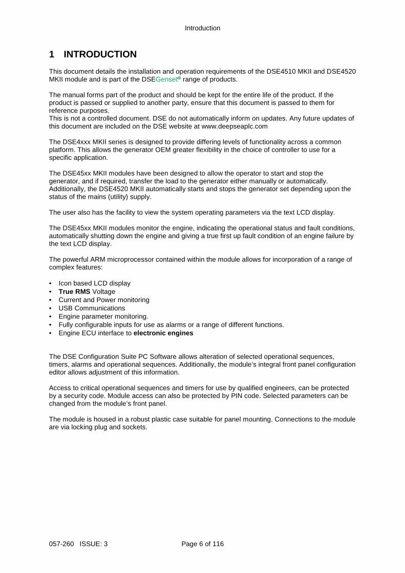
1 INTRODUCTION This document details the installation and operation requirements of the DSE4510 MKII and DSE4520 MKII module and is part of the DSEGenset® range of products. The manual forms part of the product and should be kept for the entire life of the product. If the product is passed or supplied to another party, ensure that this document is passed to them for reference purposes. This is not a controlled document. DSE do not automatically inform on updates. Any future updates of this document are included on the DSE website at www.deepseaplc.com The DSE4xxx MKII series is designed to provide differing levels of functionality across a common platform. This allows the generator OEM greater flexibility in the choice of controller to use for a specific application. The DSE45xx MKII modules have been designed to allow the operator to start and stop the generator, and if required, transfer the load to the generator either manually or automatically. Additionally, the DSE4520 MKII automatically starts and stops the generator set depending upon the status of the mains (utility) supply. The user also has the facility to view the system operating parameters via the text LCD display. The DSE45xx MKII modules monitor the engine, indicating the operational status and fault conditions, automatically shutting down the engine and giving a true first up fault condition of an engine failure by the text LCD display. The powerful ARM microprocessor contained within the module allows for incorporation of a range of complex features: • Icon based LCD display • True RMS Voltage • Current and Power monitoring • USB Communications • Engine parameter monitoring. • Fully configurable inputs for use as alarms or a range of different functions. • Engine ECU interface to electronic engines The DSE Configuration Suite PC Software allows alteration of selected operational sequences, timers, alarms and operational sequences. Additionally, the module’s integral front panel configuration editor allows adjustment of this information. Access to critical operational sequences and timers for use by qualified engineers, can be protected by a security code. Module access can also be protected by PIN code. Selected parameters can be changed from the module’s front panel. The module is housed in a robust plastic case suitable for panel mounting. Connections to the module are via locking plug and sockets.

Introduction
Page 7 of 116 057-260 ISSUE: 3
1.1 CLARIFICATION OF NOTATION Clarification of notation used within this publication.
NOTE:
Highlights an essential element of a procedure to e nsure correctness.
CAUTION!
Indicates a procedure or practice, which, if not st rictly observed, could result in damage or destruction of equipment.
WARNING!
Indicates a procedure or practice, which could resu lt in injury to personnel or loss of life if not followed correctly.
1.2 GLOSSARY OF TERMS Term Description DSE4000 MKII, DSE4xxx MKII
All modules in the DSE4xxx MKII range.
DSE4500 MKII, DSE45xx MKII
All modules in the DSE45xx MKII range.
DSE4510 MKII DSE4510 MKII module/controller DSE4520 MKII DSE4520 MKII module/controller CAN Controller Area Network
Vehicle standard to allow digital devices to communicate to one another. CDMA Code Division Multiple Access.
Cell phone access used in small number of areas including parts of the USA and Australia.
CT Current Transformer An electrical device that takes a large AC current and scales it down by a fixed ratio to a smaller current.
BMS Building Management System A digital/computer based control system for a building’s infrastructure.
DEF Diesel Exhaust Fluid (AdBlue) A liquid used as a consumable in the SCR process to lower nitric oxide and nitrogen dioxide concentration in engine exhaust emissions.
DM1 Diagnostic Message 1 A DTC that is currently active on the engine ECU.
DM2 Diagnostic Message 2 A DTC that was previously active on the engine ECU and has been stored in the ECU’s internal memory.
DPF Diesel Particulate Filter A filter fitted to the exhaust of an engine to remove diesel particulate matter or soot from the exhaust gas.
DPTC Diesel Particulate Temperature Controlled Filter A filter fitted to the exhaust of an engine to remove diesel particulate matter or soot from the exhaust gas which is temperature controlled.
DTC Diagnostic Trouble Code The name for the entire fault code sent by an engine ECU.
ECU/ECM Engine Control Unit/Management An electronic device that monitors engine parameters and regulates the fuelling.
FMI Failure Mode Indicator A part of DTC that indicates the type of failure, e.g. high, low, open circuit etc.
Continued over page…

Introduction
057-260 ISSUE: 3 Page 8 of 116
Term Description GSM Global System for Mobile communications. Cell phone technology used in most of
the World. HEST High Exhaust System Temperature
Initiates when DPF filter is full in conjunction with an extra fuel injector in the exhaust system to burn off accumulated diesel particulate matter or soot.
HMI Human Machine Interface A device that provides a control and visualisation interface between a human and a process or machine.
OC Occurrence Count A part of DTC that indicates the number of times that failure has occurred.
PGN Parameter Group Number A CAN address for a set of parameters that relate to the same topic and share the same transmission rate.
PLC Programmable Logic Controller A programmable digital device used to create logic for a specific purpose.
SCADA Supervisory Control And Data Acquisition A system that operates with coded signals over communication channels to provide control and monitoring of remote equipment
SCR Selective Catalytic Reduction A process that uses DEF with the aid of a catalyst to convert nitric oxide and nitrogen dioxide into nitrogen and water to reduce engine exhaust emission.
SIM Subscriber Identity Module. The small card supplied by the GSM/CDMA provider that is inserted into the cell phone, GSM modem or DSEGateway device to give GSM/GPRS connection.
SMS Short Message Service The text messaging service of mobile/cell phones.
SPN Suspect Parameter Number A part of DTC that indicates what the failure is, e.g. oil pressure, coolant temperature, turbo pressure etc.

Introduction
Page 9 of 116 057-260 ISSUE: 3
1.3 BIBLIOGRAPHY This document refers to, and is referred by the following DSE publications which are obtained from the DSE website: www.deepseaplc.com or by contacting DSE technical support: [email protected]. 1.3.1 INSTALLATION INSTRUCTIONS Installation instructions are supplied with the product in the box and are intended as a ‘quick start’ guide only. DSE Part Description 053-190 DSE4510 MKII & DSE4520 MKII Installation Instructions
1.3.2 MANUALS Product manuals are obtained from the DSE website: www.deepseaplc.com or by contacting DSE technical support: [email protected]. DSE Part Description
N/A Gencomm (MODBUS protocol for DSE controllers) 057-004 Electronic Engines and DSE Wiring Guide 057-151 DSE Configuration Suite PC Software Installation & Operation Manual 057-220 Options for Communications with DSE Controllers 057-258 DSE4510 MKII & DSE4520 MKII DSE Configuration Suite PC Software Manual

Introduction
057-260 ISSUE: 3 Page 10 of 116
1.3.3 TRAINING GUIDES Training guides are provided as ‘hand-out’ sheets on specific subjects during training sessions and contain specific information regarding to that subject. DSE Part Description
056-005 Using CTs With DSE Products 056-006 Introduction to Comms 056-010 Over Current Protection 056-022 Breaker Control 056-023 Adding New CAN Files 056-026 kW, kvar, kVA and pf. 056-029 Smoke Limiting 056-030 Module PIN Codes 056-055 Alternate Configurations 056-069 Firmware Update 056-075 Adding Language Files 056-076 Reading DSEGencom Alarms 056-079 Reading DSEGencom Status 056-080 MODBUS 056-081 Screen Heaters 056-082 Override Gencomm PLC Example 056-091 Equipotential Earth Bonding 056-092 Best Practices for Wiring Resistive Sensors 056-095 Remote Start Input Functions 056-097 USB Earth Loop and Isolation
1.3.4 THIRD PARTY DOCUMENTS The following third party documents are also referred to: Reference Description
ISBN 1-55937-879-4 IEEE Std C37.2-1996 IEEE Standard Electrical Power System Device Function Numbers and Contact Designations. Institute of Electrical and Electronics Engineers Inc
ISBN 0-7506-1147-2 Diesel generator handbook. L.L.J. Mahon ISBN 0-9625949-3-8 On-Site Power Generation. EGSA Education Committee.
Specification
Page 11 of 116 057-260 ISSUE: 3
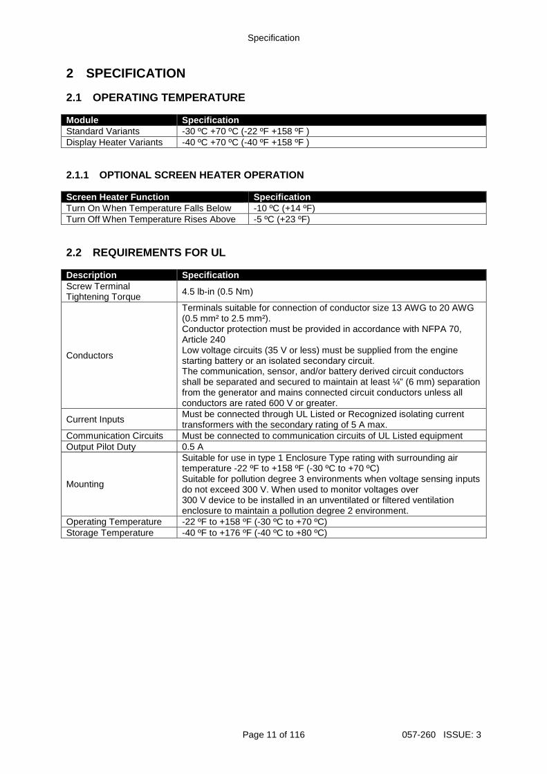
2 SPECIFICATION 2.1 OPERATING TEMPERATURE Module Specification Standard Variants -30 ºC +70 ºC (-22 ºF +158 ºF ) Display Heater Variants -40 ºC +70 ºC (-40 ºF +158 ºF ) 2.1.1 OPTIONAL SCREEN HEATER OPERATION Screen Heater Function Specification Turn On When Temperature Falls Below -10 ºC (+14 ºF) Turn Off When Temperature Rises Above -5 ºC (+23 ºF) 2.2 REQUIREMENTS FOR UL Description Specification Screw Terminal Tightening Torque 4.5 lb-in (0.5 Nm)
Conductors
Terminals suitable for connection of conductor size 13 AWG to 20 AWG (0.5 mm² to 2.5 mm²). Conductor protection must be provided in accordance with NFPA 70, Article 240 Low voltage circuits (35 V or less) must be supplied from the engine starting battery or an isolated secondary circuit. The communication, sensor, and/or battery derived circuit conductors shall be separated and secured to maintain at least ¼” (6 mm) separation from the generator and mains connected circuit conductors unless all conductors are rated 600 V or greater.
Current Inputs Must be connected through UL Listed or Recognized isolating current transformers with the secondary rating of 5 A max.
Communication Circuits Must be connected to communication circuits of UL Listed equipment Output Pilot Duty 0.5 A
Mounting
Suitable for use in type 1 Enclosure Type rating with surrounding air temperature -22 ºF to +158 ºF (-30 ºC to +70 ºC) Suitable for pollution degree 3 environments when voltage sensing inputs do not exceed 300 V. When used to monitor voltages over 300 V device to be installed in an unventilated or filtered ventilation enclosure to maintain a pollution degree 2 environment.
Operating Temperature -22 ºF to +158 ºF (-30 ºC to +70 ºC) Storage Temperature -40 ºF to +176 ºF (-40 ºC to +80 ºC)

Specification
057-260 ISSUE: 3 Page 12 of 116
2.3 TERMINAL SPECIFICATION Description Specification
Connection Type
Two part connector. Male part fitted to module Female part supplied in module packing case - Screw terminal, rising clamp, no internal spring.
Example showing cable entry and screw
terminals of a 10 way connector
Minimum Cable Size 0.5 mm² (AWG 20) Maximum Cable Size 2.5 mm² (AWG 13) Tightening Torque 0.5 Nm (4.5 lb-in) Wire Strip Length 7 mm (9/32”) 2.4 POWER SUPPLY REQUIREMENTS Description Specification Minimum Supply Voltage 8 V continuous, 5 V for up to 1 minute.
Cranking Dropouts Able to survive 0 V for 100 ms providing the supply was at least was greater than 5 V for 2 seconds before the dropout and recovers to 5 V afterwards.
Maximum Supply Voltage 35 V continuous (60 V protection) Reverse Polarity Protection -35 V continuous
Maximum Operating Current 96 mA at 12 V 85 mA at 24 V
Maximum Standby Current 51 mA at 12 V 47 mA at 24 V
Maximum Current When In Sleep Mode
35 mA at 12 V 32 mA at 24 V
Maximum Current When In Deep Sleep Mode
Less than 10 μA at 12 V Less than 10 μA at 24 V
Typical Power (Controller On, Heater Off)
3.8 W to 4.1 W
Typical Power (Controller On, Heater On)
6.8 W to 7.1 W
2.4.1 MODULE SUPPLY INSTRUMENTATION DISPLAY Description Specification Range 0 V to 70 V DC (Maximum continuous operating voltage of 35 V DC) Resolution 0.1 V Accuracy 1 % full scale (±0.35 V)
Specification
Page 13 of 116 057-260 ISSUE: 3
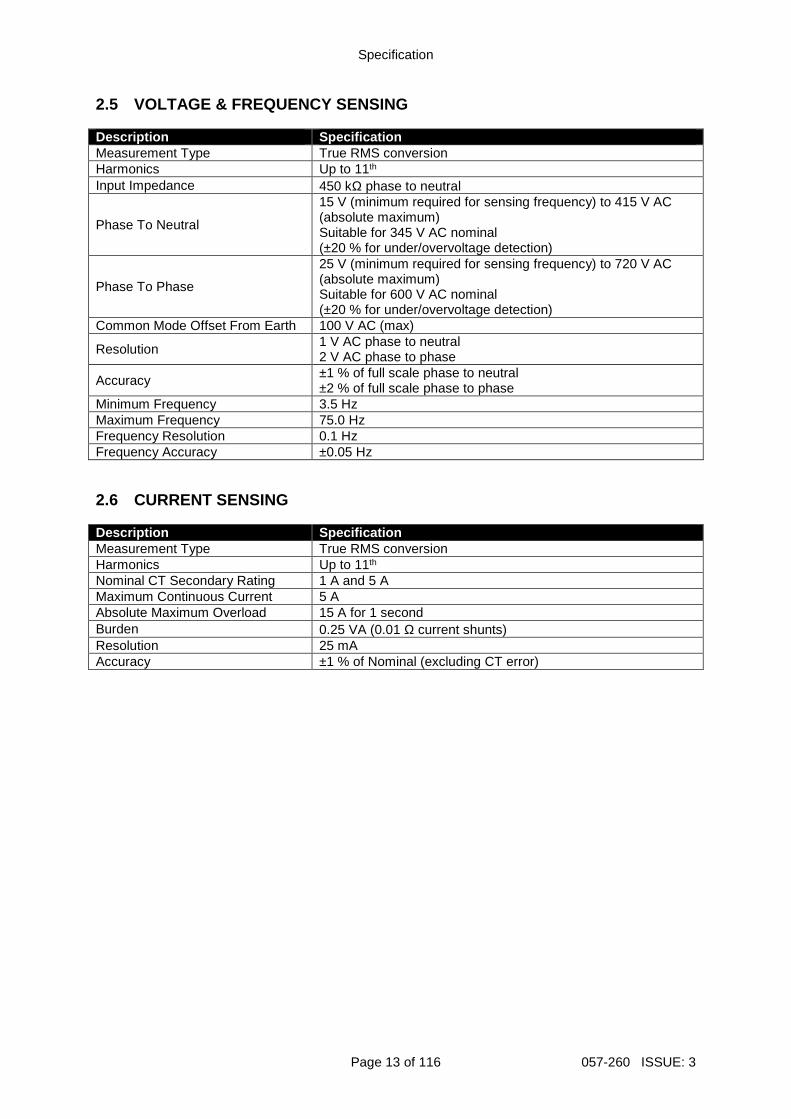
2.5 VOLTAGE & FREQUENCY SENSING Description Specification Measurement Type True RMS conversion Harmonics Up to 11th Input Impedance 450 kΩ phase to neutral
Phase To Neutral
15 V (minimum required for sensing frequency) to 415 V AC (absolute maximum) Suitable for 345 V AC nominal (±20 % for under/overvoltage detection)
Phase To Phase
25 V (minimum required for sensing frequency) to 720 V AC (absolute maximum) Suitable for 600 V AC nominal (±20 % for under/overvoltage detection)
Common Mode Offset From Earth 100 V AC (max)
Resolution 1 V AC phase to neutral 2 V AC phase to phase
Accuracy ±1 % of full scale phase to neutral ±2 % of full scale phase to phase
Minimum Frequency 3.5 Hz Maximum Frequency 75.0 Hz Frequency Resolution 0.1 Hz Frequency Accuracy ±0.05 Hz 2.6 CURRENT SENSING Description Specification Measurement Type True RMS conversion Harmonics Up to 11th Nominal CT Secondary Rating 1 A and 5 A Maximum Continuous Current 5 A Absolute Maximum Overload 15 A for 1 second Burden 0.25 VA (0.01 Ω current shunts) Resolution 25 mA Accuracy ±1 % of Nominal (excluding CT error)

Specification
057-260 ISSUE: 3 Page 14 of 116
2.6.1 VA RATING OF THE CTS
NOTE: Details for 4 mm² cables are shown for refere nce only. The connectors on the DSE modules are only suitable for cables up to 2.5 mm². The VA burden of the module on the CTs is 0.25 VA. However depending upon the type and length of cabling between the CTs and the module, CTs with a greater VA rating than the module are required. The distance between the CTs and the measuring module should be estimated and cross-referenced against the chart opposite to find the VA burden of the cable itself. If the CTs are fitted within the alternator top box, the star point (common) of the CTs should be connected to system ground (earth) as close as possible to the CTs. This minimises the length of cable used to connect the CTs to the DSE module. Example: If 1.5 mm² cable is used and the distance from the CT to the measuring module is 20 m, then the burden of the cable alone is approximately 15 VA. As the burden of the DSE controller is 0.25 VA, then a CT with a rating of at least 15 VA + 0.25 VA = 15.25 VA
must be used. If 2.5 mm² cables are used over the same distance of 20 m, then the burden of the cable on the CT is approximately 7 VA. CT’s required in this instance is at least 7.25 VA (7 + 0.25).

Specification
Page 15 of 116 057-260 ISSUE: 3
2.6.2 CT POLARITY
NOTE: Take care to ensure correct polarity of the C T primary as shown above. If in doubt, check with the CT supplier. Take care to ensure the correct polarity of the CTs. Incorrect CT orientation leads to negative kW readings when the set is supplying power. Take note that paper stick-on labels on CTs that show the orientation are often incorrectly placed on the CT. It is more reliable to use the labelling in the case moulding as an indicator to orientation (if available). To test orientation, run the generator in island mode (not in parallel with any other supply) and load the generator to around 10 % of the set rating. Ensure the DSE module shows positive kW for all three individual phase readings.
To Generator
To Load
Polarity of CT Primary
2.6.3 CT PHASING Take particular care that the CTs are connected to the correct phases. For instance, ensure that the CT on phase 1 is connected to the terminal on the DSE module intended for connection to the CT for phase 1. Additionally ensure that the voltage sensing for phase 1 is actually connected to generator phase 1. Incorrect connection of the phases as described above results in incorrect power factor (pf) measurements, which in turn results in incorrect kW measurements. One way to check for this is to make use of a single-phase load. Place the load on each phase in turn, run the generator and ensure the kW value appears in the correct phase. For instance if the load is connected to phase 3, ensure the kW figure appears in phase 3 display and not in the display for phase 1 or 2. 2.6.4 CT CLASS Ensure the correct CT type is chosen. For instance if the DSE module is providing over current protection, ensure the CT is capable of measuring the overload level required to protect against, and at the accuracy level required. For instance, this may mean fitting a protection class CT (P15 type) to maintain high accuracy while the CT is measuring overload currents. Conversely, if the DSE module is using the CT for instrumentation only (current protection is disabled or not fitted to the controller), then measurement class CTs can be used. Again, bear in mind the accuracy required. The DSE module is accurate to better than 1% of the full-scale current reading. To maintain this accuracy, fit a Class 0.5 or Class 1 CT. Check with the CT manufacturer for further advice on selecting CTs.
Labelled as p1, k or K
Labelled as p2, l or L

Specification
057-260 ISSUE: 3 Page 16 of 116
2.7 INPUTS 2.7.1 DIGITAL INPUTS Description Specification
Number 4 configurable digital inputs (7 when Analogue Inputs are configured as digital inputs)
Arrangement Contact between terminal and ground Low Level Threshold 3.2 V minimum High Level Threshold 8.1 V maximum Maximum Input Voltage +60 V DC with respect to module DC supply negative Minimum Input Voltage -24 V DC with respect to module DC supply negative Contact Wetting Current 6 mA typical Open Circuit Voltage 12 V typical
Specification
Page 17 of 116 057-260 ISSUE: 3
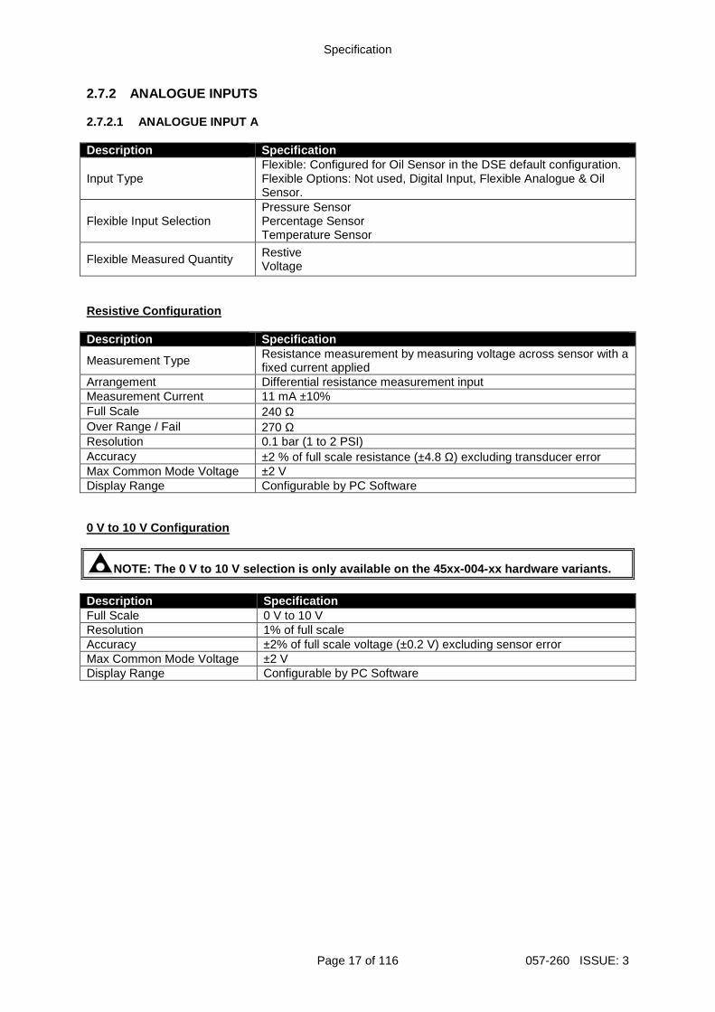
2.7.2 ANALOGUE INPUTS 2.7.2.1 ANALOGUE INPUT A Description Specification
Input Type Flexible: Configured for Oil Sensor in the DSE default configuration. Flexible Options: Not used, Digital Input, Flexible Analogue & Oil Sensor.
Flexible Input Selection Pressure Sensor Percentage Sensor Temperature Sensor
Flexible Measured Quantity Restive Voltage
Resistive Configuration Description Specification
Measurement Type Resistance measurement by measuring voltage across sensor with a fixed current applied
Arrangement Differential resistance measurement input Measurement Current 11 mA ±10% Full Scale 240 Ω Over Range / Fail 270 Ω Resolution 0.1 bar (1 to 2 PSI) Accuracy ±2 % of full scale resistance (±4.8 Ω) excluding transducer error Max Common Mode Voltage ±2 V Display Range Configurable by PC Software 0 V to 10 V Configuration
NOTE: The 0 V to 10 V selection is only available o n the 45xx-004-xx hardware variants. Description Specification Full Scale 0 V to 10 V Resolution 1% of full scale Accuracy ±2% of full scale voltage (±0.2 V) excluding sensor error Max Common Mode Voltage ±2 V Display Range Configurable by PC Software

Specification
057-260 ISSUE: 3 Page 18 of 116
2.7.2.2 ANALOGUE INPUT B Description Specification Input Type Coolant Temperature Sensor or Digital Input
Measurement Type Resistance measurement by measuring voltage across sensor with a fixed current applied
Arrangement Differential resistance measurement input Measurement Current 11 mA ±10% Full Scale 480 Ω Over Range / Fail 600 Ω Resolution ±1 % of full scale Accuracy ±2% of full scale resistance (±9.6 Ω) excluding transducer error Max Common Mode Voltage ±2 V Display Range Configurable by PC Software 2.7.2.3 ANALOGUE INPUT C Description Specification Input Type Fuel Level Sensor, Flexible Sensor or Digital Input Flexible Input Selection Pressure Sensor, Percentage Sensor or Temperature Sensor
Measurement Type Resistance measurement by measuring voltage across sensor with a fixed current applied
Arrangement Differential resistance measurement input Measurement Current 11 mA ±10 % Full Scale 480 Ω Over Range / Fail 600 Ω Resolution ±1 % of full scale Accuracy ±2 % of full scale resistance (±9.6 Ω) excluding sensor error Max Common Mode Voltage ±2 V Display Range Configurable by PC Software 2.7.3 CHARGE FAIL INPUT The charge fail input is actually a combined input and output. Whenever the generator is required to run, the terminal provides excitation current to the charge alternator field winding. When the charge alternator is correctly charging the battery, the voltage of the terminal is close to the plant battery supply voltage. In a failed charge situation, the voltage of this terminal is pulled down to a low voltage. It is this drop in voltage that triggers the Charge Failure alarm. The level at which this operates and whether this triggers a warning or shutdown alarm is configurable using the DSE Configuration Suite Software. Description Specification Minimum Voltage 0 V Maximum Voltage 35 V Resolution 0.2 V Accuracy ±1 % of full scale Excitation Active circuit constant power output Output Power 2.5 W nominal at 12 V and 24 V Current At 12V 210 mA Current At 24V 105 mA

Specification
Page 19 of 116 057-260 ISSUE: 3
2.8 OUTPUTS 2.8.1 DC OUTPUTS A & B (FUEL & START) Description Specification
Type Normally used as Fuel & Start outputs. Fully configurable for other purposes if the module is configured to control an electronic engine, supplied from DC supply terminal 2.
Rating 10 A resistive for 10 seconds, 5 A resistance continuous at module supply. 2.8.2 DC OUTPUTS C, D, E & F Description Specification Type Fully configurable, supplied from DC supply terminal 2. Rating 2 A resistive at module supply. 2.9 COMMUNICATION PORTS
NOTE: All communication ports can be used at the sa me time. Description Specification
USB Slave Port Type B USB 2.0 For connection to PC running DSE Configuration Suite Max distance 6 m (20 feet)
CAN Port
NOTE: For additional length, the DSE124 CAN & MSC E xtender is available. For more information, refer to DSE Pu blication: 057-116 DSE124 Operator Manual Engine CAN Port Standard implementation of ‘Slow mode’, up to 250 kb/s Non-Isolated. Internal Termination provided (120 Ω) Max distance 40 m (133 feet)

Specification
057-260 ISSUE: 3 Page 20 of 116
2.10 COMMUNICATION PORT USAGE 2.10.1 USB SLAVE PORT (PC CONFIGURATION)
NOTE: DSE stock 2 m (6.5 feet) USB type A to type B cable, DSE Part Number: 016-125. Alternatively they are purchased from any PC or IT store.
NOTE: The DC supply must be connected to the module for configuration by PC.
NOTE: For further details of module configuration, refer to DSE Publication: 057-258 DSE4510 MKII & DSE4520 MKII Configuration Suite PC Software Manual. The USB port is provided to give a simple means of connection between a PC and the controller. Using the DSE Configuration Suite Software, the operator is then able to control the module, starting or stopping the engine, selecting operating modes, etc. Additionally, the various operating parameters (such as coolant temperature, oil pressure, etc.) of the engine are available to be viewed or changed. To connect a module to a PC by USB, the following items are required:
DSE45xx MKII Controller
DSE Configuration Suite PC Software (Supplied on configuration suite software CD or available from www.deepseaplc.com).
USB cable Type A to Type B. (This is the same cable as often used between a PC and a USB printer) DSE can supply this cable if required : PC Configuration interface lead (USB type A – type B) DSE Part No 016-125

Specification
Page 21 of 116 057-260 ISSUE: 3
2.10.2 CAN PORT (J1939)
NOTE: For further details of module configuration, refer to DSE Publication: 057-258 DSE4510 MKII & DSE4520 MKII Configuration Suite PC Software Manual.
NOTE: For further details on connection to electron ic engines, refer to DSE Publication: 057-004 Electronic Engines And DSE Wiring
NOTE: Screened 120 ΩΩΩΩ impedance cable specified for use with CAN must be used for the CAN link. DSE stock and supply Belden cable 9841 which is a h igh quality 120 ΩΩΩΩ impedance cable suitable for CAN use (DSE part number 016-030)
NOTE: For additional length, the DSE124 CAN & MSC E xtender is available. For more information, refer to DSE Publication: 057-116 DSE124 Operator Manual
The modules are fitted with a CAN interface as standard and are capable of receiving engine data from engine ECU/ECMs compliant with the CAN J1939 standard. ECU/ECMs monitor the engine’s operating parameters such as speed,
oil pressure, coolant temperature (among others) in order to closely monitor and control the engine. The industry standard communications interface (CAN) transports data gathered by the engine’s ECU/ECM using the J1939 protocol. This allows engine controllers such as DSE to access these engine parameters with no physical connection to the sensor device. The ECU Port is used for point-to-point cable connection of more than one device and allows for connection to CAN Scanner, PLC and CAN controllers (to name just a few devices). The operator is then able to view the various operating parameters.

Specification
057-260 ISSUE: 3 Page 22 of 116
2.10.2.1 J1939-75
NOTE: For further details of module configuration, refer to DSE Publication: 057-258 DSE4510 MKII & DSE4520 MKII Configuration Software Manual. When the J1939-75 is enabled in the module’s configuration, the module’s AC measurements and alarms are sent onto the CANbus using the ECU Port to be received by an external monitoring device. There are two check boxes to enable each of the two parts of the interface as shown below, AC measurement and AC related alarms. The module AC alarms are translated into J1939 DM1 diagnostic messages. There are no additional display screens visible on the module when these options are selected.
The default CAN source address for additional J1939-75 messages is 44 however this may be changed by the generator supplier.

Specification
Page 23 of 116 057-260 ISSUE: 3
Transmitted PGNs PGN Message PGN Decimal Update Rate ACS 64913 250 ms DD 65276 1000 ms DM1 65226 1000 ms EC2 64895 Request EEC1 61444 100 ms EEC4 65214 Request EFLP1 65263 500 ms EOI 64914 250 ms ET1 65262 1000 ms GAAC 65030 100 ms GC1 64915 100 ms GPAAC 65027 100 ms GPAACP 65026 100 ms GPAACR 65025 100 ms GPBAC 65024 100 ms GPBACP 65023 100 ms GPBACRP 65022 100 ms GPCAC 65021 100 ms GPCACP 65020 100 ms GPCACR 65019 100 ms GTACPP 64911 250 ms GTACE 65018 100 ms GTACER 64910 250 ms GTACP 65029 100 ms GTACR 65028 100 ms HOURS 65253 Request VEP1 65271 1000 ms VREP 64934 100 ms

Specification
057-260 ISSUE: 3 Page 24 of 116
DM1 Conditions Key Value Low Fault - Least Severe 17 High Fault - Least Severe 15 Low Fault - Most Severe 1 High Fault - Most Severe 0 Erratic - Incorrect Data 2 Generator Alarm Condition SPN Warning FMI Shutdown FMI Generator Average AC Frequency Under 2436 17 1 SPN Generator Average Line-Line AC RMS Voltage Over
2436 15 0
Generator Average Line-Line AC RMS Voltage Under 2440 17 1 Generator Average Line-Line AC RMS Voltage Over 2440 15 0 Generator Average Line-Neutral AC RMS Voltage Under 2444 17 1 Generator Average Line-Neutral AC RMS Voltage Over 2444 15 0 Generator Average AC RMS Current Over 2448 15 0
NOTE: The availability of the Engine Alarm SPN and FMI is dependent upon the engine file selected within the DSE module’s configuration. Con tact DSE technical support: [email protected] for more information. Engine Alarm Condition SPN Warning FMI Shutdown FMI Fuel Level Low 96 17 1 Oil Pressure Low (Analogue Sensor) 100 17 1 Oil Pressure Low (Digital Input) 100 17 1 Oil Pressure Sensor Fault 100 2 2 Coolant Temperature High (Analogue Sensor) 110 15 0 Coolant Temperature High (Digital Input) 110 15 0 Coolant Temperature Sensor Fault 110 2 2 Charge Alternator Failed 167 17 1 Plant Battery Voltage High 168 15 0 Plant Battery Voltage Low 168 17 1 Overspeed 190 15 0 Underspeed 190 17 1

Specification
Page 25 of 116 057-260 ISSUE: 3
Alternator Measurements
NOTE: For further information regarding the J1939-7 5 interface, refer to SAE International J1939 Digital Annex. PGN Message PGN SPN Instrument Scaling Units ACS 64913 3545 Generator Breaker Status List 0 to 7 3546 Mains (Utility) Breaker Status List 0 to 7 GC1 64915 3567 Generator Control Not in Automatic List 0 to 3 GAAC 65030 2436 Generator Average AC Frequency 128 Hz 2440 Generator Average Line Line AC RMS
Voltage 1 V
2444 Generator Average Line Neutral AC RMS Voltage
1 V
2448 Generator Average AC RMS Current 1 A GPAAC 65027 2437 Generator Phase A AC Frequency 128 Hz 2441 Generator Phase A Line Line AC RMS
Voltage 1 V
2445 Generator Phase A Line Neutral AC RMS Voltage
1 V
2449 Generator Phase A AC RMS Current 1 A GPAACP 65026 2453 Generator Phase A Real Power 1 W 2461 Generator Phase A Apparent Power 1 VA GPAACR 65025 2457 Generator Phase A Reactive Power 1 var GPBAC 65024 2438 Generator Phase B AC Frequency 128 Hz 2442 Generator Phase B Line Line AC RMS
Voltage 1 V
2446 Generator Phase B Line Neutral AC RMS Voltage
1 V
2450 Generator Phase B AC RMS Current 1 A GPBACP 65023 2454 Generator Phase B Real Power 1 W 2462 Generator Phase B Apparent Power 1 VA GPBACRP 65022 2458 Generator Phase B Reactive Power 1 var GPCAC 65021 2439 Generator Phase C AC Frequency 128 Hz 2443 Generator Phase C Line Line AC RMS
Voltage 1 V
2447 Generator Phase C Line Neutral AC RMS Voltage
1 V
2451 Generator Phase C AC RMS Current 1 A GPCACP 65023 2455 Generator Phase C Real Power 1 W 2463 Generator Phase C Apparent Power 1 VA GPCACR 65019 2459 Generator Phase C Reactive Power 1 var GTACPP 64911 3590 Generator Total Power as Percentage 1 % GTACE 65018 2468 Generator Accumulated Energy (kWh) 1 kWh GTACER 64910 3593 Generator Accumulated Energy (kvarh) 1 kvarh GTACP 65029 2452 Generator Total Real Power 1 W 2460 Generator Total Apparent Power 1 VA GTACR 65028 2456 Generator Total Reactive Power 1 var 2464 Generator Overall Power Factor 2518 Generator Overall Power Factor Lagging Lead/Lag

Specification
057-260 ISSUE: 3 Page 26 of 116
Generator and Mains (Utility) Breaker Status List PGN ACS Value Description 0 Open 1 Closed 2 to 5 Reserved 6 Not Available 7 Reserved Generator Control Not In Automatic Status List PGN GC1 Value Description 0 In Automatic 1 Not in Automatic 2 Reserved 3 Not Available Engine Instrumentation
NOTE: The availability of the Engine Instrumentatio n PGNs are dependent upon the engine file selected within the DSE module’s config uration. Contact DSE technical support: [email protected] for more information. PGN Message PGN SPN Instrument Scaling Units DD
65276 96 Fuel Level 0.4 %/bit, 0 % to 100 %
%
EC2 64895 3670 Maximum Crank Attempts Per Start Attempt
1 count/bit 0 offset
EEC1 61444 190 Engine Speed 0.125 rpm/bit, 0 rpm to 8031.875 rpm
rpm
EEC4 65214 3671 Crank Attempt Count On Present Start Attempt
1 count/bit 0 offset
EFL_P1 65263 100 Oil Pressure 4 kPa/bit 0 kPa to 1000 kPa
kPa
EOI 64914 3607 Emergency Stop 1 = Estop 0 = No Estop
ET1 65262 110 Coolant Temperature 1 °C/bit, -40 °C Offset -40 °C to 210 °C
°C
HOURS 65253 247 Engine Run Hours 0.05 hours/bit, 0 offset
Hours
VEP1 65271 167 Charge Alternator Voltage 0.05 V/bit, 0 V to 3212.75 V
V
168 Plant Battery Voltage 0.05 V/bit, 0 V to 3212.75 V
V

Specification
Page 27 of 116 057-260 ISSUE: 3
2.11 ADDING AN EXTERNAL SOUNDER If an external alarm or indicator be required, this is achievable by using the DSE Configuration Suite PC software to configure an auxiliary output for Audible Alarm, and by configuring an auxiliary input for Alarm Mute. The audible alarm output activates and de-activates at the same time as the module’s internal sounder. The Audible Alarm output de-activates when the Alarm Mute input activates or after the Audible Alarm Duration time has ceased. Example of configuration to achieve external sounder with external alarm mute button or an automatic mute after 1 minute and 30 seconds:

Specification
057-260 ISSUE: 3 Page 28 of 116
2.12 ACCUMULATED INSTRUMENTATION
NOTE: When an accumulated instrumentation value exc eeds the maximum number as listed below, the value is reset and begins countin g from zero again. The number of logged Engine Hours and Number of Starts can be set/reset using the DSE Configuration Suite PC software. Depending upon module configuration, this may have been PIN number locked by the generator supplier. Description Specification
Engine Hours Run Maximum 99999 hrs 59 minutes (Approximately 11yrs 4 months)
Number of Starts 1,000,000 (1 Million) Accumulated Power 999999 kWh / kvarh / kVAh 2.13 DIMENSIONS AND MOUNTING 2.13.1 DIMENSIONS 140 mm x 113 mm x 43 mm (5.5 ” x 4.4 ” x 1.7 ”) 2.13.2 PANEL CUTOUT 118 mm x 92 mm (4.6 ” x 3.6 ”) 2.13.3 WEIGHT 0.16 kg (0.35 lb)

Specification
Page 29 of 116 057-260 ISSUE: 3
2.13.4 FIXING CLIPS
NOTE: In conditions of excessive vibration, mount t he module on suitable anti-vibration mountings. The module is held into the panel fascia using the supplied fixing clips. • Withdraw the fixing clip screw (turn anticlockwise) until only the pointed end is protruding from the
clip. • Insert the two ‘prongs’ of the fixing clip into the slots in the side of the module case. • Pull the fixing clip backwards (towards the back of the module) ensuring all three prongs of the
clip are inside their allotted slots. • Turn the fixing clip screws clockwise until they make contact with the panel fascia. • Turn the screw a quarter of a turn to secure the module into the panel fascia. Care must be taken
not to over tighten the fixing clip screws.
Fixing clip fitted to module
Fixing clip

Specification
057-260 ISSUE: 3 Page 30 of 116
2.13.5 OPTIONAL SILICON SEALING GASKET
NOTE: For purchasing a silicon gasket from DSE, see the section entitled Maintenance, Spares, Repair and Servicing elsewhere in this docu ment. The silicon gasket provides improved sealing between module and the panel fascia. The gasket is fitted to the module before installation into the panel fascia. Take care to ensure the gasket is correctly fitted to the module to maintain the integrity of the seal.
Gasket fitted to module
Sealing gasket

Specification
Page 31 of 116 057-260 ISSUE: 3
2.14 APPLICABLE STANDARDS Standard Description BS 4884-1 This document conforms to BS4884-1 1992 Specification for presentation of
essential information. BS 4884-2 This document conforms to BS4884-2 1993 Guide to content BS 4884-3 This document conforms to BS4884-3 1993 Guide to presentation BS EN 60068-2-1 (Minimum temperature)
-30 °C (-22 °F)
BS EN 60068-2-2 (Maximum temperature)
+70 °C (158 °F)
BS EN 60068-2-6 (Vibration)
Ten sweeps in each of three major axes 5 Hz to 8 Hz at ± 7.5 mm 8 Hz to 500 Hz at 2 gn
BS EN 60068-2-27 (Shock)
Three shocks in each of three major axes 15 gn in 11 ms
BS EN 60068-2-30 (Damp heat cyclic)
20°C to 55 °C at 95% relative humidity for 48 hours
BS EN 60068-2-78 (Damp heat static)
40 °C at 95% relative humidity for 48 hours
BS EN 60950 (Electrical safety)
Safety of information technology equipment, including electrical business equipment
BS EN 61000-6-2 (Electro-magnetic Compatibility)
EMC Generic Immunity Standard (Industrial)
BS EN 61000-6-4 (Electro-magnetic Compatibility)
EMC Generic Emission Standard (Industrial)
BS EN 60529 (Degrees of protection provided by enclosures)
IP65 (front of module when installed into the control panel with the optional sealing gasket) IP42 (front of module when installed into the control panel WITHOUT being sealed to the panel)
UL508 NEMA rating (Approximate)
12 (Front of module when installed into the control panel with the optional sealing gasket). 2 (Front of module when installed into the control panel WITHOUT being sealed to the panel)
IEEE C37.2 (Standard Electrical Power System Device Function Numbers and Contact Designations)
Under the scope of IEEE 37.2, function numbers can also be used to represent functions in microprocessor devices and software programs. The controller is device number 11L-8000 (Multifunction device protecting Line (generator) –module). As the module is configurable by the generator OEM, the functions covered by the module vary. Depending on module configuration, the device numbers included within the module could be: 2 – Time Delay Starting Or Closing Relay 3 – Checking Or Interlocking Relay 5 – Stopping Device 6 – Starting Circuit Breaker 8 – Control Power Disconnecting Device 10 – Unit Sequence Switch 11 – Multifunction Device 12 – Overspeed Device 14 – Underspeed Device
Continued over the page...

Specification
057-260 ISSUE: 3 Page 32 of 116
Standard Description IEEE C37.2 (Standard Electrical Power System Device Function Numbers and Contact Designations)
Continued… 26 – Apparatus Thermal Device 27AC – AC Undervoltage Relay 27DC – DC Undervoltage Relay 29 – Isolating Contactor Or Switch 30 – Annunciator Relay 31 – Separate Excitation Device 42 – Running Circuit Breaker 50 – Instantaneous Overcurrent Relay 52 – AC Circuit Breaker 53 – Exciter Or DC Generator Relay 54 – Turning Gear Engaging Device 59AC – AC Overvoltage Relay 59DC – DC Overvoltage Relay 62 – Time Delay Stopping Or Opening Relay 63 – Pressure Switch 71 – Level Switch 74 – Alarm Relay 81 – Frequency Relay 83 – Automatic Selective Control Or Transfer Relay 86 – Lockout Relay
In line with our policy of continual development, Deep Sea Electronics, reserve the right to change specification without notice.

Specification
Page 33 of 116 057-260 ISSUE: 3
2.14.1 ENCLOSURE CLASSIFICATIONS 2.14.1.1 IP CLASSIFICATIONS The modules specification under BS EN 60529 Degrees of protection provided by enclosures IP65 (Front of module when module is installed into the control panel with the optional sealing gasket). IP42 (front of module when module is installed into the control panel WITHOUT being sealed to the panel)
First Digit
Second Digit
Protection against contact and ingress of solid objects Protection against ingress of water 0 No protection 0 No protection 1 Protected against ingress solid objects with a
diameter of more than 50 mm. No protection against deliberate access, e.g. with a hand, but large surfaces of the body are prevented from approach.
1 Protection against dripping water falling vertically. No harmful effect must be produced (vertically falling drops).
2 Protected against penetration by solid objects with a diameter of more than 12 mm. Fingers or similar objects prevented from approach.
2 Protection against dripping water falling vertically. There must be no harmful effect when the equipment (enclosure) is tilted at an angle up to 15° from its normal position (drops falling at an angle).
3 Protected against ingress of solid objects with a diameter of more than 2.5 mm. Tools, wires etc. with a thickness of more than 2.5 mm are prevented from approach.
3 Protection against water falling at any angle up to 60° from the vertical. There must be no harmful effect (spray water).
4 Protected against ingress of solid objects with a diameter of more than 1 mm. Tools, wires etc. with a thickness of more than 1 mm are prevented from approach.
4 Protection against water splashed against the equipment (enclosure) from any direction. There must be no harmful effect (splashing water).
5 Protected against harmful dust deposits. Ingress of dust is not totally prevented but the dust must not enter in sufficient quantity to interface with satisfactory operation of the equipment. Complete protection against contact.
5 Protection against water projected from a nozzle against the equipment (enclosure) from any direction. There must be no harmful effect (water jet).
6 Protection against ingress of dust (dust tight). Complete protection against contact.
6 Protection against heavy seas or powerful water jets. Water must not enter the equipment (enclosure) in harmful quantities (splashing over).
2.14.1.2 NEMA CLASSIFICATIONS
NOTE: There is no direct equivalence between IP / N EMA ratings. IP figures shown are approximate only. 12 (Front of module when module is installed into the control panel with the optional sealing gasket). 2 (Front of module when module is installed into the control panel WITHOUT being sealed to the panel)
1 IP30
Provides a degree of protection against contact with the enclosure equipment and against a limited amount of falling dirt.
2 IP31
Provides a degree of protection against limited amounts of falling water and dirt.
3 IP64
Provides a degree of protection against windblown dust, rain and sleet; undamaged by the formation of ice on the enclosure.
3R IP32
Provides a degree of protection against rain and sleet:; undamaged by the formation of ice on the enclosure.
4 (X) IP66
Provides a degree of protection against splashing water, windblown dust and rain, hose directed water; undamaged by the formation of ice on the enclosure. (Resist corrosion).
12/12K IP65
Provides a degree of protection against dust, falling dirt and dripping non corrosive liquids.
13 IP65
Provides a degree of protection against dust and spraying of water, oil and non corrosive coolants.

Installation
057-260 ISSUE: 3 Page 34 of 116
3 INSTALLATION The module is designed to be mounted on the panel fascia. For dimension and mounting details, see the section entitled Dimension and Mounting elsewhere in this document. 3.1 USER CONNECTIONS
NOTE: Availability of some terminals depends upon m odule version. Full details are given in the section entitled Terminal Description elsewhere in this manual. To aid user connection, icons are used on the rear of the module to help identify terminal functions. An example of this is shown below.
Terminals 1-9 Terminals 10-20
Terminals 21-24 Terminals 29-32
USB PC Configuration
Terminals 25-28 UL Ratings

Installation
Page 35 of 116 057-260 ISSUE: 3
3.2 CONNECTION DESCRIPTIONS 3.2.1 DC SUPPLY, DC OUTPUTS & CHARGE FAIL INPUT
NOTE: When the module is configured for operation w ith an electronic engine, Fuel and Start output requirements may be different. For further details on connection to electronic engines, refer to DSE Publication: 057-004 Electronic Engines And DSE Wiring
NOTE: For further details of module configuration, refer to DSE Publication: 057-258 DSE4510 MKII & DSE4520 MKII Configuration Suite PC Software Manual. Pin No Description Cable
Size Notes
1 DC Plant Supply Input (Negative)
2.5mm² AWG 13
2 DC Plant Supply Input (Positive)
2.5 mm² AWG 13 Supplies the module and DC Outputs A, B, C, D, E & F
3 DC Output A (FUEL) 2.5mm² AWG 13
Plant Supply Positive from terminal 2. 10 A for 10 seconds, 5 A resistive continuous Fixed as FUEL relay if electronic engine is not configured.
4 DC Output B (START) 2.5mm² AWG 13
Plant Supply Positive from terminal 2. 10 A for 10 seconds, 5 A resistive continuous Fixed as START relay if electronic engine is not configured.
5 Charge Fail / Excite 2.5mm² AWG 13
Do not connect to ground (battery negative). If charge alternator is not fitted, leave this terminal disconnected.
6 DC Output C 1.0mm² AWG 18 2 Amp rated from module supply.
7 DC Output D 1.0mm² AWG 18
2 Amp rated from module supply.
8 DC Output E 1.0mm² AWG 18 2 Amp rated from module supply.
9 DC Output F 1.0mm² AWG 18
2 Amp rated from module supply.
Installation
057-260 ISSUE: 3 Page 36 of 116
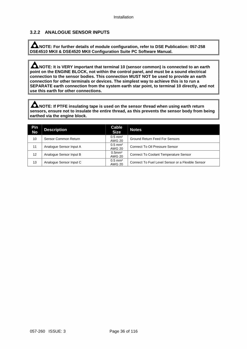
3.2.2 ANALOGUE SENSOR INPUTS
NOTE: For further details of module configuration, refer to DSE Publication: 057-258 DSE4510 MKII & DSE4520 MKII Configuration Suite PC Software Manual.
NOTE: It is VERY important that terminal 10 (sensor common) is connected to an earth point on the ENGINE BLOCK, not within the control p anel, and must be a sound electrical connection to the sensor bodies. This connection MU ST NOT be used to provide an earth connection for other terminals or devices. The simp lest way to achieve this is to run a SEPARATE earth connection from the system earth sta r point, to terminal 10 directly, and not use this earth for other connections.
NOTE: If PTFE insulating tape is used on the sensor thread when using earth return sensors, ensure not to insulate the entire thread, as this prevents the sensor body from being earthed via the engine block. Pin No Description Cable
Size Notes
10 Sensor Common Return 0.5 mm² AWG 20 Ground Return Feed For Sensors
11 Analogue Sensor Input A 0.5 mm² AWG 20
Connect To Oil Pressure Sensor
12 Analogue Sensor Input B 0.5mm² AWG 20 Connect To Coolant Temperature Sensor
13 Analogue Sensor Input C 0.5 mm² AWG 20
Connect To Fuel Level Sensor or a Flexible Sensor
Installation
Page 37 of 116 057-260 ISSUE: 3
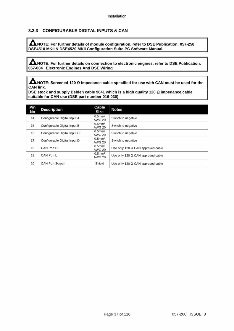
3.2.3 CONFIGURABLE DIGITAL INPUTS & CAN
NOTE: For further details of module configuration, refer to DSE Publication: 057-258 DSE4510 MKII & DSE4520 MKII Configuration Suite PC Software Manual.
NOTE: For further details on connection to electron ic engines, refer to DSE Publication: 057-004 Electronic Engines And DSE Wiring
NOTE: Screened 120 ΩΩΩΩ impedance cable specified for use with CAN must be used for the CAN link. DSE stock and supply Belden cable 9841 which is a h igh quality 120 ΩΩΩΩ impedance cable suitable for CAN use (DSE part number 016-030) Pin No Description Cable
Size Notes
14 Configurable Digital Input A 0.5mm² AWG 20 Switch to negative
15 Configurable Digital Input B 0.5mm² AWG 20 Switch to negative
16 Configurable Digital Input C 0.5mm² AWG 20 Switch to negative
17 Configurable Digital Input D 0.5mm² AWG 20 Switch to negative
18 CAN Port H 0.5mm² AWG 20 Use only 120 Ω CAN approved cable
19 CAN Port L 0.5mm² AWG 20 Use only 120 Ω CAN approved cable
20 CAN Port Screen Shield Use only 120 Ω CAN approved cable

Installation
057-260 ISSUE: 3 Page 38 of 116
3.2.4 GENERATOR & MAINS VOLTAGE & FREQUENCY SENSING
NOTE: The below table describes connections to a th ree phase, four wire alternator. For alternative wiring topologies, see the section enti tled Alternate Topology Wiring Diagrams elsewhere in this document.
NOTE: Terminals 25 to 28 are not fitted to DSE4510 MKII Pin No Description Cable
Size Notes
21 Generator L1 (U) Voltage Sensing 1.0 mm² AWG 18
Connect to Generator L1 (U) output (AC) (Recommend 2 A fuse)
22 Generator L2 (V) Voltage Sensing 1.0 mm² AWG 18
Connect to Generator L2 (V) output (AC) (Recommend 2 A fuse)
23 Generator L3 (W) Voltage Sensing 1.0 mm² AWG 18
Connect to Generator L3 (W) output (AC) (Recommend 2 A fuse)
24 Generator Neutral (N) Input 1.0 mm² AWG 18
Connect to Generator Neutral terminal (AC)
25 Mains L1 (R) Voltage Monitoring 1.0mm² AWG 18
Connect to Mains L1 (R) output (AC) (Recommend 2A fuse)
26 Mains L2 (S) Voltage Monitoring 1.0mm² AWG 18
Connect to Mains L2 (S) output (AC) (Recommend 2A fuse)
27 Mains L3 (T) Voltage Monitoring 1.0mm² AWG 18
Connect to Mains L3 (T) output (AC) (Recommend 2A fuse)
28 Mains Neutral (N) Input 1.0mm² AWG 18
Connect to Mains Neutral terminal (AC)

Installation
Page 39 of 116 057-260 ISSUE: 3
3.2.5 CURRENT TRANSFORMERS
WARNING!: Do not disconnect this plug when the CTs are carrying current. Disconnection open circuits the secondary of the C. T.’s and dangerous voltages may then develop. Always ensure the CTs are not carrying cur rent and the CTs are short circuit connected before making or breaking connections to the module.
NOTE: The module has a burden of 0.25 VA on the CT. Ensure the CT is rated for the burden of the controller, the cable length being us ed and any other equipment sharing the CT. If in doubt, consult with the CT supplier.
NOTE: Take care to ensure correct polarity of the C T primary as shown below. If in doubt, consult with the CT supplier. Pin No Description Cable
Size Notes
29 CT Secondary for L1 2.5mm² AWG 13 Connect to s1 secondary of L1 monitoring CT
30 CT Secondary for L2 2.5mm² AWG 13 Connect to s1 secondary of L2 monitoring CT
31 CT Secondary for L3 2.5mm² AWG 13 Connect to s1 secondary of L3 monitoring CT
32 CT Common 2.5mm² AWG 13
3.2.5.1 CT CONNECTIONS p1, k or K is the primary of the CT that ‘points’ towards the Generator p2, l or L is the primary of the CT that ‘points’ towards the Load s1 is the secondary of the CT that connects to the DSE Module’s input for the CT measuring s2 is the secondary of the CT that should be commoned with the s2 connections of all the other CTs and connected to the CT common terminal of the module.
To Generator
To Load
Polarity of CT Primary
Labelled as p1, k or K
Labelled as p2, l or L

Installation
057-260 ISSUE: 3 Page 40 of 116
3.2.6 USB SLAVE (PC CONFIGURATION) CONNECTOR
NOTE: The USB connection cable between the PC and t he module must not be extended beyond 5 m (yards). For distances over 5 m, it is p ossible to use a third party USB extender. Typically, they extend USB up to 50 m. The supply a nd support of this type of equipment is outside the scope of Deep Sea Electronics PLC.
CAUTION!: Care must be taken not to overload the PC s USB system by connecting more than the recommended number of USB devices to the P C. For further information, consult your PC supplier.
NOTE: For further details of module configuration, refer to DSE Publication: 057-258 DSE4510 MKII & DSE4520 MKII Configuration Suite PC Software Manual. Description Cable
Size Notes
Socket for connection to PC with DSE Configuration Suite Software
0.5 mm² AWG 20
This is a standard USB type A to type B connector.

Installation
Page 41 of 116 057-260 ISSUE: 3
3.3 TYPICAL WIRING DIAGRAM As every system has different requirements, these diagrams show only a typical system and do not intend to show a complete system. Genset manufacturers and panel builders may use these diagrams as a starting point; however always refer to the completed system diagram provided by the system manufacturer for complete wiring detail. Further wiring suggestions are available in the following DSE publications, available at www.deepseaplc.com to website members. DSE Part Description
056-005 Using CTs With DSE Products 056-022 Breaker Control 056-091 Equipotential Earth Bonding 056-092 Best Practices for Wiring Resistive Sensors 057-004 Electronic Engines and DSE Wiring

Installation
057-260 ISSUE: 3 Page 42 of 116
3.3.1 DSE4510 MKII TYPICAL WIRING DIAGRAM (3 PHASE 4 WIRE)

Installation
Page 43 of 116 057-260 ISSUE: 3
3.3.2 DSE4520 MKII TYPICAL WIRING DIAGRAM (3 PHASE 4 WIRE)
NOTE: It is possible to have a different AC topolog y for the Mains and Generator supplies. For further details of module configuration, refer to DSE Publication: 057-258 DSE4510 MKII & DSE4520 MKII Configuration Suite PC Software Manual .

Installation
057-260 ISSUE: 3 Page 44 of 116
3.3.3 EARTH SYSTEMS 3.3.3.1 NEGATIVE EARTH The typical wiring diagrams located within this document show connections for a negative earth system (the battery negative connects to Earth). 3.3.3.2 POSITIVE EARTH When using a DSE module with a Positive Earth System (the battery positive connects to Earth), the following points must be followed: Follow the typical wiring diagram as normal for all sections except the earth points. All points shown as Earth on the typical wiring diagram should connect to battery negative (not earth). 3.3.3.3 FLOATING EARTH Where neither the battery positive nor battery negative terminals are connected to earth the following points must to be followed: Follow the typical wiring diagram as normal for all sections except the earth points. All points shown as Earth on the typical wiring diagram should connect to battery negative (not earth).

Installation
Page 45 of 116 057-260 ISSUE: 3
3.4 ALTERNATE TOPOLOGY WIRING DIAGRAMS 3.4.1 GENERATOR

Installation
057-260 ISSUE: 3 Page 46 of 116
3.4.2 MAINS (DSE4520 MKII ONLY)

Description of Controls
Page 47 of 116 057-260 ISSUE: 3
4 DESCRIPTION OF CONTROLS
CAUTION: The module may instruct an engine start ev ent due to external influences. Therefore, it is possible for the engine to start a t any time without warning. Prior to performing any maintenance on the system, it is recommended th at steps are taken to remove the battery and isolate supplies.
NOTE: The following descriptions detail the sequenc es followed by a module containing the standard ‘factory configuration’. Always refer to your configuration source for the exact sequences and timers observed by any particular mod ule in the field. Control of the module is via push buttons mounted on the front of the module with
Stop/Reset Mode , Auto Mode and Manual/Start Mode functions. For normal operation, these are the only controls which need to be operated. Details of their operation are provided later in this document.
Manual / Start Mode
Auto Mode
Stop / Reset Mode
Menu Navigation
Module Display
Stop / Reset Mode LED. Will flash
upon Electrical Trip and Shutdown
Fault
Manual / Start Mode LED. Will flash
upon Waiting in Manual
Mode
Description of Controls
057-260 ISSUE: 3 Page 48 of 116
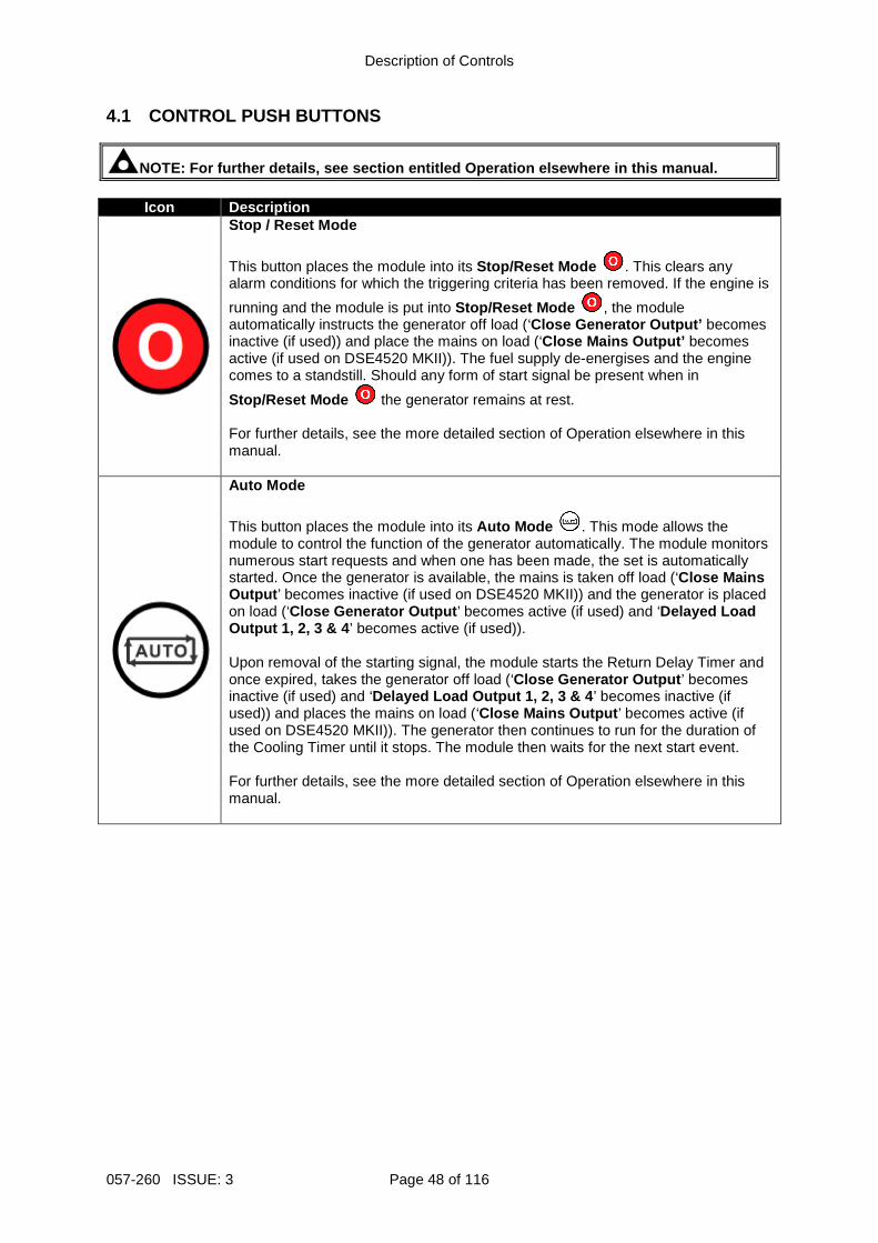
4.1 CONTROL PUSH BUTTONS
NOTE: For further details, see section entitled Operation elsewhere in this manual.
Icon Description
Stop / Reset Mode
This button places the module into its Stop/Reset Mode . This clears any alarm conditions for which the triggering criteria has been removed. If the engine is
running and the module is put into Stop/Reset Mode , the module automatically instructs the generator off load (‘Close Generator Output’ becomes inactive (if used)) and place the mains on load (‘Close Mains Output’ becomes active (if used on DSE4520 MKII)). The fuel supply de-energises and the engine comes to a standstill. Should any form of start signal be present when in
Stop/Reset Mode the generator remains at rest. For further details, see the more detailed section of Operation elsewhere in this manual.
Auto Mode
This button places the module into its Auto Mode . This mode allows the module to control the function of the generator automatically. The module monitors numerous start requests and when one has been made, the set is automatically started. Once the generator is available, the mains is taken off load (‘Close Mains Output ’ becomes inactive (if used on DSE4520 MKII)) and the generator is placed on load (‘Close Generator Output ’ becomes active (if used) and ‘Delayed Load Output 1, 2, 3 & 4 ’ becomes active (if used)). Upon removal of the starting signal, the module starts the Return Delay Timer and once expired, takes the generator off load (‘Close Generator Output ’ becomes inactive (if used) and ‘Delayed Load Output 1, 2, 3 & 4 ’ becomes inactive (if used)) and places the mains on load (‘Close Mains Output ’ becomes active (if used on DSE4520 MKII)). The generator then continues to run for the duration of the Cooling Timer until it stops. The module then waits for the next start event. For further details, see the more detailed section of Operation elsewhere in this manual.

Description of Controls
Page 49 of 116 057-260 ISSUE: 3
NOTE: For further details, see section entitled Operation elsewhere in this manual.
Icon Description
Manual/Start Mode This button starts the generator and runs it off load. To place the generator on load digital inputs are required to provide the loading/unloading instruction.
If the engine is running off-load in Manual/Start Mode and a Remote Start Signal becomes present, the module automatically instructs the changeover device to take the mains off load (‘Close Mains Output ’ becomes inactive (if used on DSE4520 MKII)) and place the generator on load (‘Close Generator Output ’ becomes active (if used) and ‘Delayed Load Output 1, 2, 3 & 4 ’ becomes active (if used)). Upon removal of the Remote Start Signal, the generator remains on load until
Stop/Reset Mode or Auto Mode are selected. For further details, see the more detailed section of Operation elsewhere in this manual.
Menu Navigation Used for navigating the instrumentation, event log and configuration screens.

Description of Controls
057-260 ISSUE: 3 Page 50 of 116
4.2 MODULE DISPLAY The module’s display contains the following sections. Description of each section can be viewed in the sub sections.
NOTE: Depending upon the module’s configuration, so me display screens may be disabled. For further details of module configurati on, refer to DSE Publication: 057-258 DSE4510 MKII & DSE4520 MKII Configuration Suite PC Software Manual.
Inst. Icon Instrumentation Unit Alarm
Icon Active Config Instrumentation Unit
Mode Icon
FPE / Auto Run
Instrumentation Unit
Load Switching Icons
Example of DSE4510 MKII Home Page Display
L1N 230 V
L2N 230 V
L3N 230 V
Example of DSE4520 MKII Home Page Display
230 V L1N 230 V
230 V L2N 230 V
230 V L3N 230 V

Description of Controls
Page 51 of 116 057-260 ISSUE: 3
4.2.1 INSTRUMENTATION ICONS When viewing instrumentation pages, an icon is displayed in the Inst. Icon section to indicate what section is currently being displayed.
Icon Details
The default home page which displays generator voltage and mains voltage (DSE4520 MKII only) or engine tier 4 information
Generator and mains voltage (DSE4520 MKII only)
/ Generator voltage and frequency instrumentation screen
Mains voltage and frequency instrumentation screen (DSE4520 MKII only)
Generator current instrumentation screen
Mains current instrumentation screen (DSE4520 MKII only when CT in load location)
Load power instrumentation screen
Engine speed instrumentation screen
Hours run instrumentation screen
Battery voltage instrumentation screen
Oil pressure instrumentation screen
Coolant temperature instrumentation screen
Flexible sensor instrumentation screen
Appears when the event log is being displayed
Current time held in the unit
The current value of the scheduler run time and duration
ECU diagnostic trouble codes
Oil filter maintenance timers
Air filter maintenance timers
Fuel filter maintenance timers
Engine oil temperature (measured from CAN) instrumentation screen
Inlet manifold temperature (measured from CAN) instrumentation screen
Exhaust temperature 1 (measured from CAN) instrumentation screen
Exhaust temperature 2 (measured from CAN) instrumentation screen
Coolant pressure 1 (measured from CAN) instrumentation screen
Coolant pressure 2 (measured from CAN) instrumentation screen
Continued overleaf…

Description of Controls
057-260 ISSUE: 3 Page 52 of 116
Icon Details
Turbo pressure 1 (measured from CAN) instrumentation screen
Turbo pressure 2 (measured from CAN) instrumentation screen
Fuel consumption (measured from CAN) instrumentation screen
Fuel pressure (measured from CAN) instrumentation screen
Total fuel used (measured from CAN) instrumentation screen
Soot level as a percentage (measured from CAN) instrumentation screen
Ash level as a % (measured from CAN) instrumentation screen
DEF tank level (measured from CAN) instrumentation screen
DEF fluid temperature (measured from CAN) instrumentation screen
DEF consumption (measured from CAN) instrumentation screen
String of text for DEF inducement reason (taken from CAN)
String of text for DEF inducement severity (taken from CAN)
EGR pressure (measured from CAN) instrumentation screen
EGR temperature (measured from CAN) instrumentation screen
Ambient air temperature (measured from CAN) instrumentation screen
Air intake temperature (measured from CAN) instrumentation screen
Configurable received CAN instrumentation screens 1 to 10

Description of Controls
Page 53 of 116 057-260 ISSUE: 3
4.2.2 ACTIVE CONFIGURATION An icon is displayed in the Active Config section to indicate the active configuration within the currently selected within the controller.
Icon Details
Appears when the main configuration is selected.
Appears when the alternative configuration 1 is selected.
Appears when the alternative configuration 2 is selected.
Appears when the alternative configuration 3 is selected.
4.2.3 FRONT PANEL EDITOR (FPE) / AUTO RUN ICON
NOTE: For further details about the Front Panel Edi tor, see the section entitled ‘Front Panel Editor’ elsewhere in this manual.
When running in Auto Mode and on the Home ( / ) page, an icon is displayed in the FPE / Auto Run section to indicate the source of the auto start signal.
Icon Auto Run Reason
Appears when a remote start input is active
Appears when a low battery run is active
Mains failure
Appears when a scheduled run is active
4.2.4 MODE ICON An icon is displayed in the Mode Icon section to indicate the mode the controller is currently in.
Icon Details
Appears when the engine is at rest and the unit is in stop mode.
Appears when the engine is at rest and the unit is in auto mode.
Appears when the engine is at rest and the unit is waiting for a manual start.
Appears when the engine is at rest and the periodic ECU wake up is active.
Appears when a timer is active, for example cranking time, crank rest etc.
Appears when the engine is running, and all timers have expired, either on or off load. The animation speed is reduced when running in idle mode.
Appears when the unit is in the front panel editor.

Description of Controls
057-260 ISSUE: 3 Page 54 of 116
4.2.5 LOAD SWITCHING ICON
NOTE: It is possible to remove the Load Switching Icons from the module’s facia. For further details of module configuration, refer to D SE Publication: 057-258 DSE4510 MKII & DSE4520 MKII Configuration Suite PC Software Manual . An icon is displayed in the Load Switching Icon section to indicate the current operation status of the controller.
Icon Details
Appears when the generator is at rest or not available and when the generator breaker is open.
Appears when the generator is at rest or not available and the generator breaker has failed to open.
Appears when the generator is available and the generator breaker is open.
Appears when the generator is available and the generator breaker is closed.
Appears when the mains supply is not available and the mains breaker is open. (DSE4520 MKII Only)
Appears when the mains supply is not available and the mains breaker is closed. (DSE4520 MKII Only)
Appears when the mains supply is available and the mains breaker is open. (DSE4520 MKII Only)
Appears when the mains supply is available and the mains breaker is closed. (DSE4520 MKII Only)
4.2.6 SPLASH SCREEN An icon is displayed across the entire screen to indicate the when the configuration of the module is changed.
Icon Details
Appears when a USB connection is made to the controller.
Appears if either the configuration file or engine file becomes corrupted.

Description of Controls
Page 55 of 116 057-260 ISSUE: 3
4.2.7 BACKLIGHT
NOTE: It is possible to turn of the LCB backlight a fter a period of inactivity. For further details of module configuration, refer to DSE Publi cation: 057-258 DSE4510 MKII & DSE4520 MKII Configuration Suite PC Software Manual. The LCD backlight is on if the unit has sufficient voltage while the unit is turned on, unless the unit is cranking for which the backlight is turned off. The unit supports an option for turning the LCD backlight off after a period of time without user interaction. The backlight may turn off during a time period of inactivity when no facia control button is pressed. The backlight turns on again when a button is pressed. Example of configuration to enable the LCD backlight to turn off after 1 minute of inactivity on the module’s facia buttons:

Description of Controls
057-260 ISSUE: 3 Page 56 of 116
4.2.8 ALARM ICONS (PROTECTIONS) An icon is displayed in the Alarm Icon section to indicate the alarm that is current active on the controller. In the event of a warning alarm, the LCD only displays the Alarm Icon . In the event of an electrical
trip or shutdown alarm, the module displays the Alarm Icon and the Stop/Reset Mode button LED begins to flash. If multiple alarms are active at the same time, the Alarm Icon automatically cycles through all the appropriate icons to indicate each alarm which is active. Example: If the DSE controller was sensing a charge alternator failure alarm, delay over current alarm and a AC under voltage alarm at the same time, it would cycle through all of the icons to show this.
Icon cycle procedure

Description of Controls
Page 57 of 116 057-260 ISSUE: 3
4.2.8.1 WARNING ALARM ICONS Warnings are non-critical alarm conditions and do not affect the operation of the engine system, they serve to draw the operators attention to an undesirable condition. By default, warning alarms are self-resetting when the fault condition is removed. However enabling All Warnings Are Latched causes warning alarms to latch until reset manually. This is enabled using the DSE Configuration Suite in conjunction with a compatible PC. Icon Fault Description
Auxiliary Inputs The module detects that an auxiliary input which has been user configured to create a fault condition has become active.
Analogue Input Configured As Digital
The analogue inputs can be configured to digital inputs. The module detects that an input configured to create a fault condition has become active.
Analogue Input High The module detects that an analogue input has risen above the high pre-alarm setting level.
Analogue Input Low The module detects that an analogue input has fallen below the low pre-alarm setting level.
Fail To Stop
The module has detected a condition that indicates that the engine is running when it has been instructed to stop.
NOTE: ‘Fail to Stop’ could indicate a faulty oil pr essure sensor. If engine is at rest check oil sensor wirin g and configuration.
Fan Speed Low The module has detected that the cooling fan speed is too low.
Charge Failure The auxiliary charge alternator voltage is low as measured from the W/L terminal.
Low Fuel Level The level detected by the fuel level sensor is below the low fuel level pre-set pre-alarm setting.
High Fuel Level The level detected by the fuel level sensor is above the high fuel
level pre-set pre-alarm setting.
Battery Under Voltage
The DC supply has fallen below or risen above the low volts pre-set pre-alarm setting.
Battery Over Voltage The DC supply has risen above the high volts pre-set pre-alarm setting.
Generator Under Voltage
The generator output voltage has fallen below the pre-set pre-alarm setting after the Safety On timer has expired.
Generator Over Voltage
The generator output voltage has risen above the pre-set pre-alarm setting.
Generator Under Frequency
The generator output frequency has fallen below the pre-set pre-alarm setting after the Safety On timer has expired.
Generator Over Frequency
The generator output frequency has risen above the pre-set pre-alarm setting.
CAN ECU Fault The engine ECU has detected an alarm
CAN Data Fail The module is configured for CAN operation and does not detect
data on the engine Can data link. Continued overleaf…

Description of Controls
057-260 ISSUE: 3 Page 58 of 116
Icon Fault Description
Immediate Over Current The measured current has risen above the configured trip level.
Delayed Over Current The measured current has risen above the configured trip level for a
configured duration.
kW Overload The measured kW has risen above the configured trip level for a
configured duration.
Oil Filter Maintenance Alarm Maintenance due for oil filter.
Air Filter Maintenance Alarm Maintenance due for air filter
Fuel Filter Maintenance Alarm Maintenance due for fuel filter.
Water In Fuel The module or engine ECU has detected there is water in the fuel.
DPTC Filter The engine ECU has detected that the DPTC Filter is active
HEST Active The engine ECU has detected that exhaust gas recirculation temperature is high.
DEF Level The engine ECU has detected that the DEF level is low.
SCR Inducement The engine ECU has detected that the SCR inducement is active
Tank Bund Level High
The module has detected that the fuel has leaked in the bund of the fuel tank.

Description of Controls
Page 59 of 116 057-260 ISSUE: 3
4.2.8.2 ELECTRICAL TRIP ALARM ICONS
NOTE: The fault condition must be resolved before t he alarm can be reset. If the fault condition remains, it is not possible to reset the alarm (the exception to this is the Coolant Temp High alarm and similar Active From Safety On alarms, as the coolant temperature could be high with the engine at rest). Electrical Trip Alarms are latching and stop the Generator but in a controlled manner. On initiation of the electrical trip condition the module de-activates the Close Gen Output outputs to remove the load from the generator. Once this has occurred the module starts the Cooling Timer and allows the engine to cool off-load before shutting down the engine. To restart the generator the fault must be cleared and the alarm reset.
Electrical Trip Alarms are latching alarms and to remove the fault, press the Stop/Reset Mode button on the module. Icon Fault Description
Auxiliary Inputs The module detects that an auxiliary input which has been user configured to create a fault condition has become active.
Analogue Input Configured As Digital
The analogue inputs can be configured to digital inputs. The module detects that an input configured to create a fault condition has become active.
Analogue Input High The module detects that an analogue input has risen above the high alarm setting level.
Analogue Input Low The module detects that an analogue input has fallen below the low alarm setting level.
Analogue Input Open Circuit The analogue input has been detected as being open circuit.
Low Fuel Level The level detected by the fuel level sensor is below the low fuel
level pre-set alarm setting.
High Fuel Level The level detected by the fuel level sensor is above the high fuel
level pre-set alarm setting.
Delayed Over Current The measured current has risen above the configured trip level for a configured duration.
kW Overload The measured kW has risen above the configured trip level for a
configured duration.
Water In Fuel The module or engine ECU has detected there is water in the fuel.
DPTC Filter The engine ECU has detected that the DPTC Filter is active
DEF Level The engine ECU has detected that the DEF level is low.
Fan Speed Low The module has detected that the cooling fan speed is too low.
SCR Inducement The engine ECU has detected that the SCR inducement is active
Tank Bund Level High
The module has detected that the fuel has leaked in the bund of the fuel tank.

Description of Controls
057-260 ISSUE: 3 Page 60 of 116
4.2.8.3 SHUTDOWN ALARM ICONS
NOTE: The fault condition must be resolved before t he alarm can be reset. If the fault condition remains, it is not possible to reset the alarm (the exception to this is the Oil Pressure Low alarm and similar Active From Safety On alarms, as the oil pressure is low with the engine at rest). Shutdown Alarms are latching and immediately stop the Generator. On initiation of the shutdown condition the module de-activates the Close Gen Output outputs to remove the load from the generator. Once this has occurred, the module shuts the generator set down immediately to prevent further damage. To restart the generator the fault must be cleared and the alarm reset.
Shutdown Alarms are latching alarms and to remove the fault, press the Stop/Reset Mode button on the module. Icon Fault Description
Auxiliary Inputs The module detects that an auxiliary input which has been user configured to create a fault condition has become active.
Analogue Input Configured As Digital
The analogue inputs can be configured to digital inputs. The module detects that an input configured to create a fault condition has become active.
Analogue Input High The module detects that an analogue input has risen above the high alarm setting level.
Analogue Input Low The module detects that an analogue input has fallen below the low alarm setting level.
Analogue Input Open Circuit The analogue input has been detected as being open circuit.
Fail To Start The engine has failed to start after the configured number of start
attempts
Low Oil Pressure
The module detects that the engine oil pressure has fallen below the low oil pressure pre-alarm setting level after the Safety On timer has expired.
Engine High Temperature
The module detects that the engine coolant temperature has exceeded the high engine temperature pre-alarm setting level after the Safety On timer has expired.
Under Speed The engine speed has fallen below the under speed pre alarm
setting
Over Speed The engine speed has risen above the over speed pre alarm setting
Charge Failure The auxiliary charge alternator voltage is low as measured from the W/L terminal.
Fan Speed Low The module detected that the cooling fan speed is too low.
Low Fuel Level The level detected by the fuel level sensor is below the low fuel level pre-set alarm setting.
High Fuel Level The level detected by the fuel level sensor is above the high fuel
level pre-set alarm setting.
Generator Under Voltage
The generator output voltage has fallen below the pre-set alarm setting after the Safety On timer has expired.
Generator Over Voltage
The generator output voltage has risen above the pre-set alarm setting.
Continued overleaf…

Description of Controls
Page 61 of 116 057-260 ISSUE: 3
Icon Fault Description
Generator Under Frequency
The generator output frequency has fallen below the pre-set alarm setting after the Safety On timer has expired.
Generator Over Frequency
The generator output frequency has risen above the pre-set alarm setting.
Delayed Over Current The measured current has risen above the configured trip level for a configured duration.
kW Overload The measured kW has risen above the configured trip level for a
configured duration.
CAN ECU Fault The engine ECU has detected an alarm – CHECK ENGINE LIGHT Contact Engine Manufacturer for support.
CAN Data Fail The module is configured for CAN operation and does not detect data on the engine Can data link.
Emergency Stop The emergency stop button has been depressed. This failsafe (normally closed to emergency stop) input and immediately stops the set should the signal be removed.
Oil Sender Open Circuit The oil pressure sensor has been detected as being open circuit.
Coolant Temperature Sender Open Circuit
The coolant temperature sensor has been detected as being open circuit.
Oil Filter Maintenance Alarm Maintenance due for oil filter.
Air Filter Maintenance Alarm Maintenance due for air filter
Fuel Filter Maintenance Alarm Maintenance due for fuel filter.
Water In Fuel The module or engine ECU has detected there is water in the fuel.
DPTC Filter The engine ECU has detected that the DPTC Filter is active
DEF Level The engine ECU has detected that the DEF level is low.
SCR Inducement The engine ECU has detected that the SCR inducement is active
Tank Bund Level High
The module has detected that the fuel has leaked in the bund of the fuel tank.

Description of Controls
057-260 ISSUE: 3 Page 62 of 116
4.3 VIEWING THE INSTRUMENT PAGES 4.3.1 NAVIGATION MENU
To enter the navigation menu, press both the (up) and (down) buttons simultaneously.
To select the required icon, press the (up) button to cycle right or the (down) button to cycle left until the desired instrumentation section is reached.
Once the desired icon is at the top, press the Auto Mode () button to enter that instrunmentation
section. If the Auto Mode () button is not pressed, the display automatically returns to the Home
( / ) page after the configured setting of the LCD Scroll Timer.

Description of Controls
Page 63 of 116 057-260 ISSUE: 3
4.3.1.1 NAVIGATION MENU ICONS
Icon Description
Home page (either engine tier 4 or generator and voltage instrumentation, depending upon module configuration)
Generator and mains voltage instrumentation
/ Generator instrumentation
Mains instrumentation (DSE4520 MKII only)
Mains load instrumentation
Current and load instrumentation
Engine instrumentation
Module information
Engine DTCs (Diagnostic Trouble Codes) if active
Event Log
Engine Tier 4 information

Description of Controls
057-260 ISSUE: 3 Page 64 of 116
4.3.2 GENERAL NAVIGATION
NOTE: For further details of module configuration, refer to DSE Publication: 057-258 DSE4510 MKII & DSE4520 MKII Configuration Suite PC Software Manual. It is possible to scroll through the display to view different pages of information by repeatedly
operating the up or down naviagation buttons. Example:
Home
Press
Generator
Press
Mains
And so on until the last page is reached.
A Further press of the down button returns the
display to the Home ( / ) page. Once selected, the page will remain on the LCD display until the user selects a different page or, after
an extended period of inactivity (Page Delay Timer), the module reverts back to the Home ( / ) page. The Page Delay Timer is configurable using the DSE Configuration Suite Software or by using the Front Panel Editor.
If you want to view one of the instrument pages towards the end of the list, it may be quicker to scroll up through the pages rather than down!

Description of Controls
Page 65 of 116 057-260 ISSUE: 3
4.3.3 HOME
NOTE: Depending upon the module’s configuration, th e home screen may be set to display electrical parameters or engine tier 4 info rmation. For further details of module configuration, refer to DSE Publication: 057-258 DSE4510 MKII & DSE4520 MKII Configuration Suite PC Software Manual. This is the page that is displayed when no other page has been selected and is automatically displayed after a period of inactivity (Page Delay Timer) of the module facia buttons. Depending upon configuration, the page contains the voltage reading of the generator and mains that is measured from the module’s voltage inputs or engine tier 4 information read from the CAN. 4.3.3.1 VOLTAGE INSTRUMENTATION
230 V L1N 230 V
230 V L2N 230 V
230 V L3N 230 V
• Generator Voltage (ph-N / ph-ph) • Mains Voltage (ph-N / ph-ph) (DSE4520 MKII only)
4.3.3.2 ENGINE TIER 4 INSTRUMENTATION
NOTE: For more information on the engine tier 4 ico ns, refer to the section entitled Engine Tier 4 Information else where in this manual.
Mains Voltage
Generator Voltage

Description of Controls
057-260 ISSUE: 3 Page 66 of 116
4.3.4 GENERATOR These pages contain electrical values of the generator, measured or derived from the module’s voltage inputs.
L1N 230 V
L2N 230 V
L3N 230 V
• Generator Voltage (ph-N) • Generator Voltage (ph-ph) • Generator Frequency
4.3.5 MAINS (DSE4520 MKII ONLY) These pages contain electrical values of the mains, measured or derived from the module’s voltage inputs.
L1N 230 V
L2N 230 V
L3N 230 V
• Mains Voltage (ph-N) • Mains Voltage (ph-ph) • Mains Frequency

Description of Controls
Page 67 of 116 057-260 ISSUE: 3
4.3.6 LOAD These pages contain electrical values of the load, measured or derived from the module’s voltage and current inputs. The power values displayed depend on which supply is on load.
L1 20 kW
L2 20 kW
L3 20 kW
• Generator Current (A) • Mains Current (A) (DSE4520 MKII only) • Load ph-N (kW) • Total Load (kW) • Load ph-N (kVA) • Total Load (kVA) • Load ph-N (kVAr) • Total Load (kVAr) • Power Factor ph-N • Power Factor Average • Accumulated Load (kWh, kVAh, kVArh)

Description of Controls
057-260 ISSUE: 3 Page 68 of 116
4.3.7 ENGINE
NOTE*: For further details of supported engine inst rumentation from CAN, refer to DSE Publication: 057-004 Electronic Engines and DSE Wiring Guide. These pages contain instrumentation gathered about the engine measured or derived from the module’s inputs, some of which may be obtained from the engine ECU.
1500 RPM
• Engine Speed • Engine Run Time • Engine Battery Voltage • Engine Charge Alternator Voltage • Engine Coolant Temperature • Engine Oil Pressure • Engine Fuel Level or Flexible Sensor • Engine Oil Temperature* • Inlet Manifold Temperature* • Exhaust Temperature 1* • Exhaust Temperature 2* • Coolant Pressure 1* • Coolant Pressure 2* • Turbo Pressure 1* • Turbo Pressure 2* • Fuel Consumption* • Fuel Pressure* • Total Fuel Used* • Soot Level* • Ash Level* • DEF Level* • DEF Temperature* • DEF Consumption* • DEF Inducement Reason* • DEF Inducement Severity* • EGR Pressure* • EGR Temperature* • Ambient Air Temp* • Air Intake Temp* • Engine Maintenance Due – Oil • Engine Maintenance Due – Air • Engine Maintenance Due – Fuel

Description of Controls
Page 69 of 116 057-260 ISSUE: 3
4.3.8 CONFIGURABLE CAN INSTRUNMENTS
NOTE: Depending upon the module’s configuration, so me display screens may be disabled. For further details of module configurati on, refer to DSE Publication: 057-258 DSE4510 MKII & DSE4520 MKII Configuration Suite PC Software Manual. The configurable CAN instruments are intended to display CAN information from external third party CAN devices such as fuel flow meters. The contents of these screens vary depending upon configuration by the engine manufacturer or supplier. Under default factory settings the configurable CAN instruments are not viewable. They are configurable by the system designer using the DSE Configuration Suite software.
89 L/h
• Configurable CAN Instrumentation 1 to 10
4.3.9 INFO These pages contain information about the controller.
13:30:00
M T W T F S S 3 Wk
2:45:00
• Module’s date and time • Scheduler settings • Product description and USB identification number • Application and Engine Version
Start time of scheduled run
Duration of scheduled run
Day and week of scheduled run
Icon to indicate that the scheduler is
currently displayed

Description of Controls
057-260 ISSUE: 3 Page 70 of 116
4.3.10 ENGINE DTC (ECU ALARMS) If the DSE module is connected to an ECU, This page contains active Diagnostic Trouble Codes (DTC) only if the engine ECU generating a fault code. These are alarm conditions are detected by the engine ECU and displayed by the DSE controller. 4.3.10.1 VIEWING ACTIVE ENGINE DTC
To view the engine DTC(s), press both (up) and (down) buttons simultaneously, the navigation
menu is then displayed. Once entered, cycle to the DTC ( ) section and enter.
To view the active DTC(s) alarms, repeatedly press the (up) or (down) buttons until the LCD screen displays the alarm.
Continuing to press the (up) or (down) buttons will cycle through the alarms.
To exit the active DTC(s) alarm section, press the (up) and (down) buttons simultaneously to enter the navigation menu. Once entered, cycle to the desired intrunmentation section.
Check engine
1 1
Low - moderate
458852, 18, 126
SPN 458862
1 1 FMI 0
A list of CAN fault icons is overleaf...
Icon to indicate that the event log is currently display
Number of DTC displayed out of number of active DTCs
Icon to indicate the type of DTC
fault that is active
Description and fault code of active
DTC alarm
SPN and FMI fault code of active
DTC alarm
Current operating state of the module

Description of Controls
Page 71 of 116 057-260 ISSUE: 3
NOTE: For details on these code meanings, refer to the ECU instructions provided by the engine manufacturer, or contact the engine manufact urer for further assistance.
NOTE: For further details on connection to electron ic engines, refer to DSE Publication: 057-004 Electronic Engines And DSE Wiring Icon Fault DTC Description
Check Engine Fault The engine ECU has detected a fault not recognised by the DSE module, contact engine manufacturer for support.
Low Oil Pressure The engine ECU has detected that the engine oil pressure has fallen below its configured low oil pressure alarm level.
Under Speed The engine ECU has detected that the engine speed has fallen
below its configured under speed alarm level.
Over Speed The engine ECU has detected that the engine speed has risen
above its configured over speed alarm level.
Charge Failure The engine ECU has detected that the engine’s charge alternator
output has fallen below its configured alarm level.
Low Fuel Level The engine ECU has detected that the engine’s fuel level has fallen below its configured low fuel level alarm.
Battery Under/Over Voltage
The engine ECU has detected that the engine’s DC supply has fallen below or risen above its configured alarm level.

Description of Controls
057-260 ISSUE: 3 Page 72 of 116
4.3.11 EVENT LOG This module’s event log contains a list of the last 50 record electrical trips, shutdowns, mains fails, mains returns and power up events and the engine hours at which they occurred. Once the log is full, any subsequent electrical trip or shutdown alarms overwrites the oldest entry in the log. Hence, the log always contains the most recent shutdown alarms. The module logs the alarm, along with the engine running hours. 4.3.11.1 VIEWING THE EVENT LOG
To view the event log, press both (up) and (down) buttons simultaneously, the navigation
menu is then displayed. Once entered, cycle to the Event Log ( ) section and enter.
To view the event log, repeatedly press the (up) or (down) buttons until the LCD screen displays the desired event.
Continuing to press down the (up) or (down) buttons will cycle through the past alarms after which the display shows the most recent alarm and the cycle begins again.
To exit the event log, press the (up) and (down) buttons simultaneously to enter the navigation menu. Once entered, cycle to the desired intrunmentation section.
13:30:00
11 50
M T W T F S S Week 1
The events shown in the below table are recorded into the module’s event log in addition to all electrical trip and shutdown alarms. Icon Event Description
Mains Failure The mains supply was detected as failed as it had risen above or fallen below the pre-set alarm setting.
Mains Return The mains supply was detected as healthy as it was not longer in a fault condition
Module Power Up The module was powered up
Icon to indicate that the event log is currently display
Number of event displayed
out of 15
Current operating state of the module
Icon to indicate the electrical trip
or shutdown alarm that has been recorded
Time and date the event occurred.

Description of Controls
Page 73 of 116 057-260 ISSUE: 3
4.3.12 ENGINE TIER 4 INFORMATION
NOTE: For further details of module configuration, refer to DSE Publication: 057-258 DSE4510 MKII & DSE4520 MKII Configuration Software Manual.
NOTE: For details on these icon meanings, refer to the ECU instructions provided by the engine manufacturer, or contact the engine manufact urer for further assistance.
NOTE: For further details on connection to electron ic engines, refer to DSE Publication: 057-004 Electronic Engines And DSE Wiring If the DSE module is connected to an ECU, This page contains active Engine Tier 4 Lamps only if the engine ECU is generating a fault code. These are alarm conditions are detected by the engine ECU and displayed by the DSE controller.
To view the Engine Tier 4 Lamps or DPF Inhibit Control page, press the (up) or (down) buttons until the LCD screen displays the desired event.
Continuing to press down the (up) or (down) buttons will cycle through the past alarms after which the display shows the most recent alarm and the cycle begins again.
To view the Engine Tier 4 Lamps or DPF Inhibit Control page, press both (up) and (down) buttons simultaneously, the navigation menu is then displayed. Once entered, cycle to the
Engine Tier 4 ( ) section and enter.
To view the Engine Tier 4 Lamps or DPF Inhibit Control pages, press the (up) or (down) buttons until the LCD screen displays the desired page.
To exit the Engine Tier 4 section, press the (up) and (down) buttons simultaneously to enter the navigation menu. Once entered, cycle to the desired intrunmentation section.

Description of Controls
057-260 ISSUE: 3 Page 74 of 116
4.3.12.1 ENGINE TIER 4 LAMPS
NOTE: Depending upon the module’s configuration, th e home screen may be set to display engine tier 4 information. For further deta ils of module configuration, refer to DSE Publication: 057-258 DSE4510 MKII & DSE4520 MKII Configuration Suite PC Software Manual.
Icon Fault Description
ECU Amber Alarm
The module received an Amber fault condition from the engine ECU.
ECU Red Alarm
The module received a Red fault condition from the engine ECU.
DPF Stop
The module received a fault indication from the engine ECU informing that the Diesel Particulate Filter has been stopped.
DPF Warning
The module received a fault condition from the engine ECU informing that the Diesel Particulate Filter has a fault condition.
HEST Active
The module received a fault indication from the engine ECU informing that the High Exhaust System Temperature is active.
DEF Low Level
The module received a fault condition from the engine ECU informing that the Diesel Exhaust Fluid Low Level is active.
SCR Inducement
The module received a fault indication from the engine ECU informing that the Selective Catalytic Reduction Inducement is active.

Description of Controls
Page 75 of 116 057-260 ISSUE: 3
4.3.12.2 DPF INHIBIT CONTROL
To inhibit or enable the DPF Control, press the Auto Mode () button.
Icon Fault Description
DPF Active
The module received a fault indication from the engine ECU informing that the Diesel Particulate Filter is active.
DPF Inhibited
The module received a fault indication from the engine ECU informing that the Diesel Particulate Filter has been inhibited.

Operation
057-260 ISSUE: 3 Page 76 of 116
5 OPERATION
NOTE: The following descriptions detail the sequenc es followed by a module containing the standard ‘factory configuration’. Always refer to your configuration source for the exact sequences and timers observed by any particular mod ule in the field. 5.1 QUICKSTART GUIDE This section provides a quick start guide to the module’s operation. 5.1.1 STARTING THE ENGINE
NOTE: For further details, see the section entitled Operation elsewhere in this document.
Press the Manual/Start button

Operation
Page 77 of 116 057-260 ISSUE: 3
5.1.2 STOPPING THE ENGINE
NOTE: For further details, see the section entitled Operation elsewhere in this document.
Select Stop/Reset mode. The generator is stopped

Operation
057-260 ISSUE: 3 Page 78 of 116
5.2 STOP/RESET MODE
NOTE: If a digital input configured to Panel Lock is active, changing module modes is not possible. Viewing the instruments and event logs is NOT affected by Panel Lock .
NOTE: For further details of module configuration, refer to DSE Publication: 057-258 DSE4510 MKII & DSE4520 MKII Configuration Suite PC Software Manual.
Stop/Reset Mode is activated by pressing the Stop/Reset Mode button.
The Stop/Reset icon is displayed to indicate Stop/Reset Mode operations.
In Stop/Reset Mode , the module removes the generator from load (if necessary) before stopping the generator.
If the generator does not stop when requested, the Fail To Stop alarm is activated (subject to the setting of the Fail to Stop timer). To detect the engine at rest the following must occur:
• Engine speed is zero as detected by the CAN ECU • Generator AC Voltage and Frequency must be zero. • Engine Charge Alternator Voltage must be zero. • Oil pressure sensor must indicate low oil pressure
When the engine has stopped and the module is in the Stop/Reset Mode , it is possible to send configuration files to the module from DSE Configuration Suite PC software and to enter the Front Panel Editor to change parameters.
Any latched alarms that have been cleared are reset when Stop/Reset Mode is entered.
The engine is not started when in Stop/Reset Mode . If start signals are given, the input is
ignored until Auto Mode is entered.
When the unit is configured for `Power Save Mode’ and has been left in Stop/Reset Mode with no presses of the fascia buttons, the module enters Power Save Mode. To ‘wake’ the module, press any fascia control buttons or activate Digital Input A. The same is true for Deep Sleep Mode.
Power Save & Deep Sleep Mode in the DSE Configuration Suite Software

Operation
Page 79 of 116 057-260 ISSUE: 3
5.3 AUTOMATIC MODE
NOTE: If a digital input configured to external Panel Pock is active, changing module modes is not possible. Viewing the instruments and event logs is NOT affected by Panel Lock .
Auto Mode is activated by pressing the Auto Mode button.
The Auto Mode icon is displayed to indicate Auto Mode operations if no alarms are present.
Auto Mode allows the generator to operate fully automatically, starting and stopping as required with no user intervention. 5.3.1 WAITING IN AUTO MODE If a starting request is made, the starting sequence begins. Starting requests can be from the following sources:
• Failure of mains supply (DSE4520 MKII only) • Activation of the inbuilt exercise scheduler. • Activation of an auxiliary input that has been configured to Remote Start On Load or Remote
Start Off Load. • Activation of an auxiliary input that has been configured to Auxiliary Mains Fail (DSE4520
MKII Only).

Operation
057-260 ISSUE: 3 Page 80 of 116
5.3.2 STARTING SEQUENCE
NOTE: If the unit has been configured for CAN, comp atible ECU’s receive the start command via CAN and transmit the engine speed to th e DSE controller.
NOTE: For further details of module configuration, refer to DSE Publication: 057-258 DSE4510 MKII & DSE4520 MKII Configuration Suite PC Software Manual. To allow for ‘false’ start requests, the Start Delay timer begins. Should all start requests be removed during the Start Delay timer, the unit returns to a stand-by state. If a start request is still present at the end of the Start Delay timer, the fuel relay is energised and the engine is cranked. If the engine fails to fire during this cranking attempt then the starter motor is disengaged for the Crank Rest duration after which the next start attempt is made. Should this sequence continue beyond the Set Number Of Attempts, the start sequence is terminated and the display shows Fail to
Start . The starter motor is disengaged when the engine fires. Speed detection is factory configured to be derived from the AC alternator output frequency, but can additionally be measured from a Magnetic Pickup mounted on the flywheel or from the CAN link to the engine ECU depending on module. Additionally, rising oil pressure can be used to disconnect the starter motor (but cannot detect underspeed or overspeed). After the starter motor has disengaged, the Safety On Delay timer activates, allowing Oil Pressure, High Engine Temperature, Under-speed, Charge Fail and any delayed Auxiliary fault inputs to stabilise without triggering the fault.

Operation
Page 81 of 116 057-260 ISSUE: 3
5.3.3 ENGINE RUNNING
NOTE: The load transfer signal remains inactive unt il the generator is available. This prevents excessive wear on the engine and alternato r. The generator is placed on load if configured to do so. If all start requests are removed, the Stopping Sequence begins. 5.3.4 STOPPING SEQUENCE The Return Delay timer operates to ensure that the starting request has been permanently removed and isn’t just a short term removal. Should another start request be made during the cooling down period, the set returns on load. If there are no starting requests at the end of the Return Delay timer, the load is transferred from the generator to the mains supply and the Cooling Down timer is initiated. The Cooling Down timer allows the set to run off load and cool sufficiently before being stopped. This is particularly important where turbo chargers are fitted to the engine. After the Cooling Down timer has expired, the set is stopped.

Operation
057-260 ISSUE: 3 Page 82 of 116
5.4 MANUAL/START MODE
NOTE: If a digital input configured to Panel Lock i s active, changing module modes is not possible. Viewing the instruments and event logs is NOT affected by panel lock.
To begin the starting sequence, press the Manual/Start Mode button. If ‘protected start’ is disabled, the start sequence begins immediately.
NOTE: For further details of module configuration, refer to DSE Publication: 057-258 DSE4510 MKII & DSE4520 MKII Configuration Suite PC Software Manual.
If Protected Start is enabled, the Waiting in Manual Mode icon is displayed and the LED above
the Manual/Start Mode button flashes to indicate Waiting in Manual Mode .
The Manual/Start Mode button must be pressed once more to begin the start sequence.
5.4.1 STARTING SEQUENCE
NOTE: There is no Start Delay in this mode of operation.
NOTE: If the unit has been configured for CAN, comp atible ECU’s receives the start command via CAN.
NOTE: For further details of module configuration, refer to DSE Publication: 057-258 DSE4510 MKII & DSE4520 MKII Configuration Suite PC Software Manual. The fuel relay is energised and the engine is cranked. If the engine fails to fire during this cranking attempt then the starter motor is disengaged for the Crank Rest Timer duration after which the next start attempt is made. Should this sequence continue beyond the set Number Of Attempts, the start sequence is terminated and the display shows Fail to
Start . The starter motor is disengaged when the engine fires. Speed detection is factory configured to be derived from the AC alternator output frequency, but can additionally be measured from a Magnetic Pickup mounted on the flywheel or from the CANbus link to the engine ECU depending on module configuration. Additionally, rising oil pressure can be used to disconnect the starter motor (but cannot detect underspeed or overspeed). After the starter motor has disengaged, the Safety On Delay timer activates, allowing Oil Pressure, High Engine Temperature, Under-speed, Charge Fail and any delayed Auxiliary fault inputs to stabilise without triggering the fault.
Protected Start Mode setting in the DSE Configuration Suite Software

Operation
Page 83 of 116 057-260 ISSUE: 3
5.4.2 ENGINE RUNNING
NOTE: The load transfer signal remains inactive unt il the generator is available. This prevents excessive wear on the engine and alternato r.
In Manual/Start Mode , the load is not transferred to the generator unless a ‘loading request’ is made. A loading request can come from a number of sources.
• Failure of mains supply (DSE4520 MKII only) • Activation of an auxiliary input that has been configured to Remote Start On Load or Transfer
to Generator, Open Mains • Activation of an auxiliary input that has been configured to Auxiliary Mains Fail (DSE4520
MKII Only). • Activation of the inbuilt exercise scheduler if configured for ‘on load’ runs.
Once the generator has been placed on load, it is not automatically removed. To manually remove the load either:
• Activation of an auxiliary input that has been configured to Transfer to Mains, Open Generator
• Press the Auto Mode button to return to automatic mode. The set observes all
Auto Mode start requests and stopping timers before beginning the Auto Mode Stopping Sequence.
• Press the Stop/Reset Mode button to remove load and stop the generator. • Activation of an auxiliary input that has been configured to Generator Load Inhibit.
5.4.3 STOPPING SEQUENCE
In Manual/Start Mode the set continues to run until either:
• The Stop/Reset Mode button is pressed – The delayed load outputs are de-activated immediately and the set immediately stops.
• The Auto Mode button is pressed. The set observes all Auto Mode start requests and stopping timers before beginning the Auto Mode Stopping Sequence.

Operation
057-260 ISSUE: 3 Page 84 of 116
5.5 MAINTENANCE ALARMS Depending upon module configuration one or more levels of engine maintenance alarm may occur based upon a configurable schedule. Example 1
Screen capture from DSE Configuration Suite Software showing the configuration of the Maintenance Alarm for Oil, Air and Fuel. When activated, the maintenance alarm can be either a warning (set continues to run) or shutdown (running the set is not possible). Resetting the maintenance alarm is normally actioned by the site service engineer after performing the required maintenance. The method of reset is either by: • Activating an input that has been
configured to Maintenance Reset Alarm x, where x is the type of maintenance alarm (Air, Fuel or Oil).
• Pressing the maintenance reset button in the DSE Configuration Suite, Maintenance section.
• Pressing and holding the Stop/Reset Mode button for 10 seconds on the desired Maintenance Alarm status page. This can be protected by a PIN number.
Example 2 Screen capture from DSE Configuration Suite Software showing the configuration of a digital input for Maintenance Reset Alarm Air. Example 3 Screen capture from DSE Configuration Suite Software showing the Maintenance Alarm Reset ‘button’ in the DSE Configuration Suite SCADA | MAINTENANCE section.

Operation
Page 85 of 116 057-260 ISSUE: 3
5.6 SCHEDULER The controller contains an inbuilt exercise run scheduler, capable of automatically starting and stopping the set. Up to 8 scheduled start/stop sequences can be configured to repeat on a 7-day or 28-day cycle. Scheduled runs may be on load or off load depending upon module configuration. Example Screen capture from DSE Configuration Suite Software showing the configuration of the Exercise Scheduler. In this example the set will start at 09:00 on Monday and run for 5 hours, then start at 13:30 on Tuesday and run for 30 minutes. 5.6.1 STOP MODE
• Scheduled runs do not occur when the module is in Stop/Reset Mode . 5.6.2 MANUAL MODE
• Scheduled runs do not occur when the module is in Manual/Start Mode waiting for a start request.
• Activation of a Scheduled Run ‘On Load’ when the module is operating Off Load in
Manual/Start Mode the set to run On Load. 5.6.3 AUTO MODE
• Scheduled runs operate only if the module is in Auto Mode with no Shutdown or Electrical Trip alarm active.
• If the module is in Stop/Reset Mode or Manual/Start Mode when a scheduled run
begins, the engine is not started. However, if the module is moved into Auto Mode during a scheduled run, the engine is called to start.
• Depending upon configuration by the system designer, an external input can be used to inhibit a scheduled run.
• If the engine is running Off Load in Auto Mode and a scheduled run configured to ‘On Load’ begins, the set is placed On Load for the duration of the Schedule.

Operation
057-260 ISSUE: 3 Page 86 of 116
5.8 ALTERNATIVE CONFIGURATIONS Depending upon the configuration of the system by the generator supplier, the system may have selectable configurations (for example to select between 50 Hz and 60 Hz). If this has been enabled the generator supplier will advise how this selection can be made (usually by operating an external selector switch or by selecting the required configuration file in the module’s front panel configuration editor).

Front Panel Configuration
Page 87 of 116 057-260 ISSUE: 3
6 FRONT PANEL CONFIGURATION This configuration mode allows the operator to configure the majority of the module through its display without the use of the DSE Configuration Suite PC Software. Use the module’s facia buttons to traverse the menu and make value changes to the parameters:
Previous Section (301→201→101)
Next Section (101→201→301)
Next Parameter (101→102→103)
Previous Parameter (103→102→101)
Edit or Save Parameter

Front Panel Configuration
057-260 ISSUE: 3 Page 88 of 116
6.1 ACESSING THE MAIN CONFIGURATION EDTIOR
NOTE: More comprehensive module configuration is po ssible via PC configuration software. For further details of module configurati on, refer to DSE Publication: 057- 258 DSE4510 MKII & DSE4520 MKII Configuration Suite PC Software Manual.
• Ensure the engine is at rest and the module by pressing the Stop/Reset Mode button.
• Press the Stop/Reset Mode (-) and Auto Mode () buttons together to enter the main configuration editor.
6.2 ENTERING PIN
NOTE: The PIN is not set by DSE when the module lea ves the factory. If the module has a PIN code set, the generator supplier has entered th is. Contact the generator supplier if the code is required. If the code has been ‘lost’ or ‘ forgotten’, the module must be returned to the DSE factory to have the PIN removed. A charge is ma de for this procedure. This procedure cannot be performed away from the DSE factory.
NOTE: The PIN is automatically reset when the edito r is exited (manually or automatically) to ensure security. • If a module security PIN has been set, the PIN request is then shown.
• Press the Auto Mode (), the first ‘#’ changes to ‘0’. Press the Up or Down buttons to adjust it to the correct value.
• Press the Manual/Start Mode (+) buttons to move to the next digit. The digit previously entered now shows as ‘#’ for security.
• Repeat this process for the other digits of the PIN number. Press the Stop/Reset Mode (-) button to move back to adjust one of the previous digits.
• When the Auto Mode () button is pressed after editing the final PIN digit, the PIN is checked for validity. If the number is not correct, the PIN must be re-entered.
• If the PIN has been successfully entered (or the module PIN has not been enabled), the editor is
displayed.

Front Panel Configuration
Page 89 of 116 057-260 ISSUE: 3
6.3 EDITING A PARAMETER
NOTE: Pressing and holding the Stop/Reset Mode (-) or Manual/Start Mode (+) buttons enables an auto-repeat functionality.
• Once in the selected editor, press the Up and Down navigation buttons to cycle through it in increments of 100.
• Press the Stop/Reset Mode (-) or Manual/Start Mode (+) buttons to cycle through the editor in increments of 1.
• When viewing the parameter to be edited, press the Auto Mode () button, the value begins to flash.
• Press the Stop/Reset Mode (-) or Manual/Start Mode (+) buttons to adjust the value to the required setting.
• Press the Auto Mode () button to save the current value, the value ceases flashing. 6.4 EXITING THE MAIN CONFIGURATION EDITOR
NOTE: The editor automatically exits after 5 minute s of inactivity to ensure security.
• Press and hold the Stop/Reset Mode (-) button to exit the editor without saving changes.
• Press and hold the Auto Mode () button to exit the editor and save the changes.

Front Panel Configuration
057-260 ISSUE: 3 Page 90 of 116
6.5 ADJUSTABLE PARAMETERS
NOTE: Listed parameters apply to DSE45xx MKII modul es of version 3.0.0 and above only. For a comprehensive list of adjustable parameters o n modules below version 3.0.0, refer to DSE publication: 053-190 DSE4510 MKII & DSE4520 MKII Installation In structions .
Functionality in DSE4510 MKII & DSE4520 MKII Functionality in DSE4520 MKII only.
6.5.1 MODULE SETTINGS Configuration Parameters – Module (Page 1)
101 Contrast 0 (%) 102 Fast Loading Enabled On (1), Off (0) 103 All Warnings Latched On (1), Off (0) 104 Lamp Test At Startup On (1), Off (0) 105 Power Save Mode Enable On (1), Off (0) 106 Deep Sleep Mode Enable On (1), Off (0) 107 Protected Start Enable On (1), Off (0) 108 Event Log Display Format On (1), Off (0) 109 Power Up Mode 0 (Power Up Mode) 110 DTC String Enable On (1), Off (0) 111 RESERVED 112 Pin Protected Maintenance Reset On (1), Off (0) 113 Stop Button Cooldown On (1), Off (0) 114 Use Module Oil Pressure On (1), Off (0) 115 Use Module Coolant Temp On (1), Off (0) 116 Use Module Engine Hours On (1), Off (0) 117 Use Module RPM On (1), Off (0) 118 Use Module Charge Alt On (1), Off (0) 119 Disable CAN Speed Control On (1), Off (0) 120 CT Position Gen (0), Load(1) 121 Generator Voltage Display On (1), Off (0) 122 Mains Voltage Display On (1), Off (0) 123 Generator Frequency Display On (1), Off (0) 124 Mains Frequency Display On (1), Off (0) 125 Current Display On (1), Off (0) 126 kW Display On (1), Off (0) 127 kVAr Display On (1), Off (0) 128 kVA Display On (1), Off (0) 129 pf Display On (1), Off (0) 130 kWh Display On (1), Off (0) 131 kVArh Display On (1), Off (0) 132 kVAh Display On (1), Off (0) 133 RESERVED 134 Show Load Switching Icons On (1), Off (0) 135 Backlight Inactivity Timer On (1), Off (0) 136 ECU Periodic Wake Up On (1), Off (0) 137 Coolant Temp Persistence On (1), Off (0) 138 Limit Audible Alarm Duration On (1), Off (0)
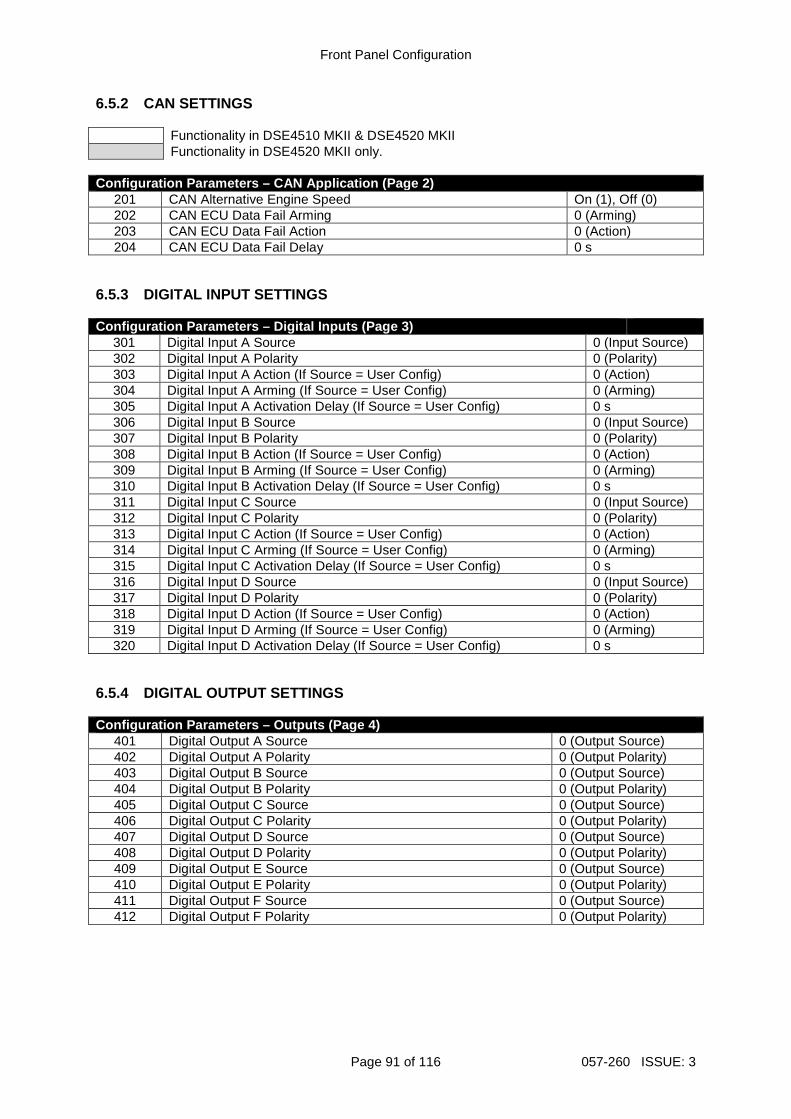
Front Panel Configuration
Page 91 of 116 057-260 ISSUE: 3
6.5.2 CAN SETTINGS
Functionality in DSE4510 MKII & DSE4520 MKII Functionality in DSE4520 MKII only.
Configuration Parameters – CAN Application (Page 2)
201 CAN Alternative Engine Speed On (1), Off (0) 202 CAN ECU Data Fail Arming 0 (Arming) 203 CAN ECU Data Fail Action 0 (Action) 204 CAN ECU Data Fail Delay 0 s
6.5.3 DIGITAL INPUT SETTINGS Configuration Parameters – Digital Inputs (Page 3)
301 Digital Input A Source 0 (Input Source) 302 Digital Input A Polarity 0 (Polarity) 303 Digital Input A Action (If Source = User Config) 0 (Action) 304 Digital Input A Arming (If Source = User Config) 0 (Arming) 305 Digital Input A Activation Delay (If Source = User Config) 0 s 306 Digital Input B Source 0 (Input Source) 307 Digital Input B Polarity 0 (Polarity) 308 Digital Input B Action (If Source = User Config) 0 (Action) 309 Digital Input B Arming (If Source = User Config) 0 (Arming) 310 Digital Input B Activation Delay (If Source = User Config) 0 s 311 Digital Input C Source 0 (Input Source) 312 Digital Input C Polarity 0 (Polarity) 313 Digital Input C Action (If Source = User Config) 0 (Action) 314 Digital Input C Arming (If Source = User Config) 0 (Arming) 315 Digital Input C Activation Delay (If Source = User Config) 0 s 316 Digital Input D Source 0 (Input Source) 317 Digital Input D Polarity 0 (Polarity) 318 Digital Input D Action (If Source = User Config) 0 (Action) 319 Digital Input D Arming (If Source = User Config) 0 (Arming) 320 Digital Input D Activation Delay (If Source = User Config) 0 s
6.5.4 DIGITAL OUTPUT SETTINGS Configuration Parameters – Outputs (Page 4)
401 Digital Output A Source 0 (Output Source) 402 Digital Output A Polarity 0 (Output Polarity) 403 Digital Output B Source 0 (Output Source) 404 Digital Output B Polarity 0 (Output Polarity) 405 Digital Output C Source 0 (Output Source) 406 Digital Output C Polarity 0 (Output Polarity) 407 Digital Output D Source 0 (Output Source) 408 Digital Output D Polarity 0 (Output Polarity) 409 Digital Output E Source 0 (Output Source) 410 Digital Output E Polarity 0 (Output Polarity) 411 Digital Output F Source 0 (Output Source) 412 Digital Output F Polarity 0 (Output Polarity)

Front Panel Configuration
057-260 ISSUE: 3 Page 92 of 116
6.5.5 TIMER SETTINGS
Functionality in DSE4510 MKII & DSE4520 MKII Functionality in DSE4520 MKII only.
Configuration Parameters – Timers (Page 5)
501 Mains Transient Delay 502 Start Delay 503 Preheat Timer 504 Crank Time 505 Crank Rest Time 506 Smoke Limiting 507 Smoke Limiting Off 508 DPF Ramp 509 Safety On Delay 510 Warm Up Time 511 Return Delay 512 Cooling Time 513 ETS Solenoid Hold 514 Failed To Stop Delay 515 Generator Transient Delay 516 Transfer Delay 517 Breaker Trip Pulse 518 Breaker Close Pulse 519 Delayed Load Output 1 520 Delayed Load Output 2 521 Delayed Load Output 3 522 Delayed Load Output 4 523 Power Save Mode Delay 524 Deep Sleep Mode Delay 525 Page Delay 526 Cooling Time at Idle 527 Backlight Power Save Delay 528 Audible Alarm Timer 529 Fuel Pull in Coil Duration 530 ECU Override Time 531 ECU Periodic Wakeup Period 532 Post-Heat Timer 533 Delay Crank Timer

Front Panel Configuration
Page 93 of 116 057-260 ISSUE: 3
6.5.6 GENERATOR SETTINGS Configuration Parameters – Generator (Page 6)
601 Alternator Fitted On (1), Off (0) 602 Alternator Poles 0 603 Under Voltage Shutdown Enable On (1), Off (0) 604 Under Voltage Trip Shutdown 0 V 605 Under Voltage Warning Enable On (1), Off (0) 606 Under Voltage Warning Trip 0 V 607 RESERVED 608 Loading Voltage 0 V 609 Over Voltage Warning Enable On (1), Off (0) 610 Over Voltage Warning Return 0 V 611 Over Voltage Warning Trip 0 V 612 Over Voltage Shutdown Trip 0 V 613 Under Frequency Shutdown Enable On (1), Off (0) 614 Under Frequency Shutdown Trip 0.0 Hz 615 Under Frequency Warning Enable On (1), Off (0) 616 Under Frequency Warning Trip 0.0 Hz 617 RESERVED 618 Loading Frequency 0.0 Hz 619 Nominal Frequency 0.0 Hz 620 Over Frequency Warning Enable On (1), Off (0) 621 Over Frequency Warning Return 0.0 Hz 622 Over Frequency Warning Trip 0.0 Hz 623 Over Frequency Shutdown Enable On (1), Off (0) 624 Over Frequency Shutdown Trip 0.0 Hz 625 Generator AC System 0 (AC System) 626 CT Primary 0 A 627 CT Secondary 1 A, 5 A 628 Full Load Rating 0 A 629 Immediate Over Current Enable On (1), Off (0) 630 Delayed Over Current Alarm Enable On (1), Off (0) 631 Delayed Over Current Alarm Action 0 (Action) 632 Over Current Delay Time 0 s 633 Over Current Trip 0 % 634 kW Rating 0 kW 635 Over kW Protection Enable On (1), Off (0) 636 Over kW Protection Action 0 (Action) 637 Over kW Protection Trip 0 % 638 Over kW Protection Trip Delay 0 s 639 Enable CT Support On (1), Off (0) 640 Over kW Protection Return 0 % 641 Nominal Voltage 0 V

Front Panel Configuration
057-260 ISSUE: 3 Page 94 of 116
6.5.7 MAINS SETTINGS
Functionality in DSE4510 MKII & DSE4520 MKII Functionality in DSE4520 MKII only.
Configuration Parameters – Mains (Page 7) 701 AC System 0 (AC System) 702 Mains Failure Detection On (1), Off (0) 703 Immediate Mains Dropout On (1), Off (0) 704 Under Voltage Enable On (1), Off (0) 705 Under Voltage Level 0 V 706 Under Voltage Return 0 V 707 Over Voltage Enable On (1), Off (0) 708 Over Voltage Return 0 V 709 Over Voltage Level Trip 0 V 710 Under Frequency Enable On (1), Off (0) 711 Under Frequency Trip 0.0 Hz 712 Under Frequency Return 0.0 Hz 713 Over Frequency Enable On (1), Off (0) 714 Over Frequency Return 0 Hz 715 Over Frequency Trip 0.0 Hz

Front Panel Configuration
Page 95 of 116 057-260 ISSUE: 3
6.5.8 ENGINE SETTINGS Configuration Parameters – Engine (Page 8)
801 Start Attempts 0 802 Over Speed Overshoot 0 % 803 Over Speed Delay 0 s 804 Gas Choke Timer (Gas Engine Only) 0 s 805 Gas On Delay (Gas Engine Only) 0 s 806 Gas Ignition Off Delay (Gas Engine Only) 0 s 807 Crank Disconnect On Oil Pressure Enable On (1), Off (0) 808 Check Oil Pressure Prior To Starting On (1), Off (0) 809 Crank Disconnect On Oil 0.00 Bar 810 Crank Disconnect On Frequency 0.0 Hz 811 Crank Disconnect On Engine Speed 0 RPM 812 Under Speed Enable On (1), Off (0) 813 Under Speed Trip 0 RPM 814 Over Speed Trip 0 RPM 815 Low Battery Voltage Enable On (1), Off (0) 816 Low Battery Voltage Warning 0.0 V 817 Low Battery Voltage Return 0.0 V 818 Low Battery Voltage Delay 0:00:00 819 High Battery Voltage Enable On (1), Off (0) 820 High Battery Voltage Return 0.0 V 821 High Battery Voltage Warning 0.0 V 822 High Battery Voltage Warning Delay 0 s 823 Charge Alt Shutdown Enable On (1), Off (0) 824 Charge Alt Shutdown Trip 0.0 V 825 Charge Alt Shutdown Delay 0 s 826 Charge Alt Warning Enable On (1), Off (0) 827 Charge Alt Warning Trip 0.0 V 828 Charge Alt Warning Delay 0 s 829 Start on Low Battery Enable On (1), Off (0) 830 Start on Low Battery Threshold 0.0 V 831 Start on Low Battery Start Delay 0 s 832 Start on Low Battery Engine Run Duration 0 s
833 - 834 RESERVED 835 J1939-75 Instruments Enable On (1), Off (0) 836 J1939-75 Alarms Enable On (1), Off (0) 837 Engine CAN Source Address On (1), Off (0) 838 Instrumentation CAN Source Address On (1), Off (0) 839 RESERVED 840 Tier 4 Home Screen Enable On (1), Off (0) 841 Start Pause Time 0 s 842 Preheat Enable On (1), Off (0) 843 Preheat Temperature 0 °C 844 Post-heat Enabled On (1), Off (0) 845 Post-heat Temperature 0 °C 846 Coolant Heater Enabled On (1), Off (0 847 Coolant Heater On Temp 0 °C 848 Coolant Heater Off Temp 0 °C 849 Coolant Cooler Enabled On (1), Off (0 850 Coolant Cooler On Temp 0 °C 851 Coolant Cooler Off Temp 0 °C 852 RESERVRED 853 Tank Bund Level High Alarm 0 (Action)
Continued overleaf…
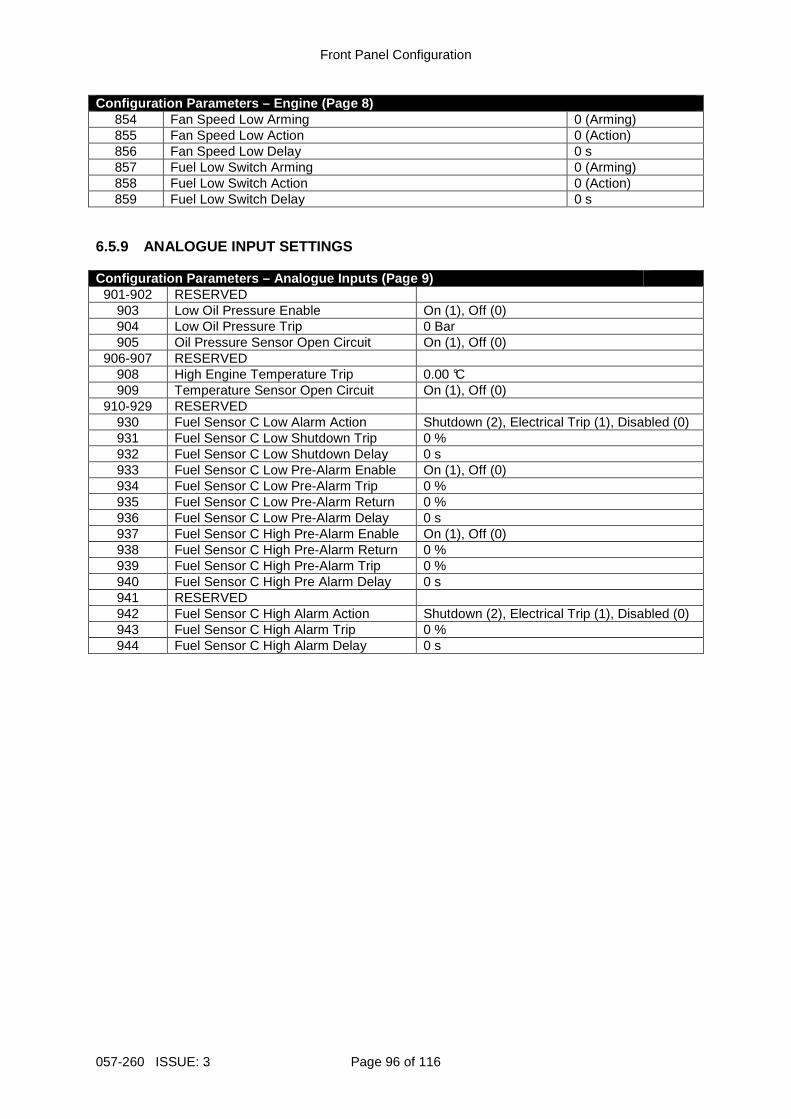
Front Panel Configuration
057-260 ISSUE: 3 Page 96 of 116
Configuration Parameters – Engine (Page 8) 854 Fan Speed Low Arming 0 (Arming) 855 Fan Speed Low Action 0 (Action) 856 Fan Speed Low Delay 0 s 857 Fuel Low Switch Arming 0 (Arming) 858 Fuel Low Switch Action 0 (Action) 859 Fuel Low Switch Delay 0 s
6.5.9 ANALOGUE INPUT SETTINGS Configuration Parameters – Analogue Inputs (Page 9)
901-902 RESERVED 903 Low Oil Pressure Enable On (1), Off (0) 904 Low Oil Pressure Trip 0 Bar 905 Oil Pressure Sensor Open Circuit On (1), Off (0)
906-907 RESERVED 908 High Engine Temperature Trip 0.00 °C 909 Temperature Sensor Open Circuit On (1), Off (0)
910-929 RESERVED 930 Fuel Sensor C Low Alarm Action Shutdown (2), Electrical Trip (1), Disabled (0) 931 Fuel Sensor C Low Shutdown Trip 0 % 932 Fuel Sensor C Low Shutdown Delay 0 s 933 Fuel Sensor C Low Pre-Alarm Enable On (1), Off (0) 934 Fuel Sensor C Low Pre-Alarm Trip 0 % 935 Fuel Sensor C Low Pre-Alarm Return 0 % 936 Fuel Sensor C Low Pre-Alarm Delay 0 s 937 Fuel Sensor C High Pre-Alarm Enable On (1), Off (0) 938 Fuel Sensor C High Pre-Alarm Return 0 % 939 Fuel Sensor C High Pre-Alarm Trip 0 % 940 Fuel Sensor C High Pre Alarm Delay 0 s 941 RESERVED 942 Fuel Sensor C High Alarm Action Shutdown (2), Electrical Trip (1), Disabled (0) 943 Fuel Sensor C High Alarm Trip 0 % 944 Fuel Sensor C High Alarm Delay 0 s

Front Panel Configuration
Page 97 of 116 057-260 ISSUE: 3
6.5.10 SCHEDULER SETTINGS Configuration Parameters – Scheduler (Page 10)
1001 Enable Scheduler On (1), Off (0) 1002 Schedule Run On or Off Load On (1), Off (0) 1003 Scheduler Period Weekly(0), Monthly(1) 1004 Start Time (Entry 1) 0:00:00 1005 Day (Entry 1) 0 (1=Monday) 1006 Week (Entry 1) 1, 2, 3 or 4 1007 Duration (Entry 1) 0 s 1008 Start Time (Entry 2) 0:00:00 1009 Day (Entry 2) 0 (1=Monday) 1010 Week (Entry 2) 1, 2, 3 or 4 1011 Duration (Entry 2) 0 s 1012 Start Time (Entry 3) 0:00:00 1013 Day (Entry 3) 0 (1=Monday) 1014 Week (Entry 3) 1, 2, 3 or 4 1015 Duration (Entry 3) 0 s 1016 Start Time (Entry 4) 0:00:00 1017 Day (Entry 4) 0 (1=Monday) 1018 Week (Entry 4) 1, 2, 3 or 4 1019 Duration (Entry 4) 0 s 1020 Start Time (Entry 5) 0:00:00 1021 Day (Entry 5) 0 (1=Monday) 1022 Week (Entry 5) 1, 2, 3 or 4 1023 Duration (Entry 5) 0 s 1024 Start Time (Entry 6) 0:00:00 1025 Day (Entry 6) 0 (1=Monday) 1026 Week (Entry 6) 1, 2, 3 or 4 1027 Duration (Entry 6) 0 s 1028 Start Time (Entry 7) 0:00:00 1029 Day (Entry 7) 0 (1=Monday) 1030 Week (Entry 7) 1, 2, 3 or 4 1031 Duration (Entry 7) 0 s 1032 Start Time (Entry 8) 0:00:00 1033 Day (Entry 8) 0 (1=Monday) 1034 Week (Entry 8) 1, 2, 3 or 4 1035 Duration (Entry 8) 0 s
6.5.11 TIME SETTINGS Configuration Parameters – Time (Page 11)
1101 Time of Day 0:00:00 1102 RESERVED 1103 RESERVED 1104 Day of Month 1-31 1105 Month of Year 1-12 1106 Year 0-99

Front Panel Configuration
057-260 ISSUE: 3 Page 98 of 116
6.5.12 MAINTENANCE ALARM SETTINGS Configuration Parameters – Maintenance Alarms (Page 12)
1201 Oil Maintenance Alarm Enable On (1), Off (0) 1202 Oil Maintenance Alarm Action 0 (Action) 1203 Oil Maintenance Alarm Engine Hours 0 h 1204 Air Maintenance Alarm Enable On (1), Off (0) 1205 Air Maintenance Alarm Action 0 (Action) 1206 Air Maintenance Alarm Engine Hours 0 h 1207 Fuel Maintenance Alarm Enable On (1), Off (0) 1208 Fuel Maintenance Alarm Action 0 (Action) 1209 Fuel Maintenance Alarm Engine Hours 0 h

Front Panel Configuration
Page 99 of 116 057-260 ISSUE: 3
6.5.13 ALTERNATIVE CONFIGURATION 1 SETTINGS
Functionality in DSE4510 MKII & DSE4520 MKII Functionality in DSE4520 MKII only.
Configuration Parameters – Alternative Configuration 1 (Page 20 )
2001 Default Configuration On (1), Off (0) 2002 Enable Configuration On (1), Off (0) 2003 CAN Alternative Engine Speed On (1), Off (0) 2004 Under Voltage Shutdown Enable On (1), Off (0) 2005 Under Voltage Shutdown Trip 0 V 2006 Under Voltage Warning Enable On (1), Off (0) 2007 Under Voltage Warning Trip 0 V 2008 Loading Voltage 0 V 2009 Over Voltage Warning Enable On (1), Off (0) 2010 Over Voltage Warning Return 0 V 2011 Over Voltage Warning Trip 0 V 2012 Over Voltage Trip 0 V 2013 Under Frequency Shutdown Enable On (1), Off (0) 2014 Under Frequency Shutdown Trip 0.0 Hz 2015 Under Frequency Warning Enable On (1), Off (0) 2016 Under Frequency Warning Trip 0.0 Hz 2017 Loading Frequency 0.0 Hz 2018 Nominal Frequency 0.0 Hz 2019 Over Frequency Warning Enable On (1), Off (0) 2020 Over Frequency Warning Return 0.0 Hz 2021 Over Frequency Warning Trip 0.0 Hz 2022 Over Frequency Shutdown Enable On (1), Off (0) 2023 Over Frequency Shutdown Trip 0.0 Hz 2024 CT Primary 0 A 2025 CT Secondary 1 A, 5 A 2026 Full Load Rating 0 A 2027 Immediate Over Current On (1), Off (0) 2028 Delayed Over Current Alarm On (1), Off (0) 2029 Delayed Over Current Alarm Action 0 (Action) 2030 Over Current Delay 00:00:00 2031 Over Current Trip 0 % 2032 Generator kW Rating 0 kW 2033 Overload Protection Enable On (1), Off (0) 2034 Overload Protection Action 0 (Action) 2035 Overload Protection Trip 0 % 2036 Overload Protection Trip Delay 0 s 2037 AC System 0 (AC system) 2038 Mains Failure Detection On (1), Off (0) 2039 Immediate Mains Dropout On (1), Off (0) 2040 Mains Under Voltage Enable On (1), Off (0) 2041 Mains Under Voltage Trip 0 V 2042 Mains Under Voltage Return 0 V 2043 Mains Over Voltage Enable On (1), Off (0) 2044 Mains Over Voltage Return 0 V 2045 Mains Over Voltage Trip 0 V 2046 Mains Under Frequency Enable On (1), Off (0) 2047 Mains Under Frequency Trip 0.0 Hz 2048 Mains Under Frequency Return 0.0 Hz
Continued overleaf…

Front Panel Configuration
057-260 ISSUE: 3 Page 100 of 116
Functionality in DSE4510 MKII & DSE4520 MKII Functionality in DSE4520 MKII only.
Configuration Parameters – Alternative Configuration 1 (Page 20 )
2049 Mains Over Frequency Enable On (1), Off (0) 2050 Mains Over Frequency Return 0.0 Hz 2051 Mains Over Frequency Trip 0.0 Hz 2052 Under Speed Shutdown Enable On (1), Off (0) 2053 Under Speed Shutdown Trip 0 RPM 2054 Over Speed Shutdown Trip 0 RPM 2055 Mains AC System 0 (AC system) 2056 Overload Protection Return 0 % 2057 Generator Nominal Voltage 0 V

Front Panel Configuration
Page 101 of 116 057-260 ISSUE: 3
6.5.14 ALTERNATIVE CONFIGURATION 2 SETTINGS
Functionality in DSE4510 MKII & DSE4520 MKII Functionality in DSE4520 MKII only.
Configuration Parameters – Alternative Configuration 2 (Page 30 )
3002 Enable Configuration On (1), Off (0) 3003 CAN Alternative Engine Speed On (1), Off (0) 3004 Under Voltage Shutdown Enable On (1), Off (0) 3005 Under Voltage Shutdown Trip 0 V 3006 Under Voltage Warning Enable On (1), Off (0) 3007 Under Voltage Warning Trip 0 V 3008 Loading Voltage 0 V 3009 Over Voltage Warning Enable On (1), Off (0) 3010 Over Voltage Warning Return 0 V 3011 Over Voltage Warning Trip 0 V 3012 Over Voltage Trip 0 V 3013 Under Frequency Shutdown Enable On (1), Off (0) 3014 Under Frequency Shutdown Trip 0.0 Hz 3015 Under Frequency Warning Enable On (1), Off (0) 3016 Under Frequency Warning Trip 0.0 Hz 3017 Loading Frequency 0.0 Hz 3018 Nominal Frequency 0.0 Hz 3019 Over Frequency Warning Enable On (1), Off (0) 3020 Over Frequency Warning Return 0.0 Hz 3021 Over Frequency Warning Trip 0.0 Hz 3022 Over Frequency Shutdown Enable On (1), Off (0) 3023 Over Frequency Shutdown Trip 0.0 Hz 3024 CT Primary 0 A 3025 CT Secondary 1 A, 5 A 3026 Full Load Rating 0 A 3027 Immediate Over Current On (1), Off (0) 3028 Delayed Over Current Alarm On (1), Off (0) 3029 Delayed Over Current Alarm Action 0 (Action) 3030 Over Current Delay 00:00:00 3031 Over Current Trip 0 % 3032 Generator kW Rating 0 kW 3033 Overload Protection Enable On (1), Off (0) 3034 Overload Protection Action 0 (Action) 3035 Overload Protection Trip 0 % 3036 Overload Protection Trip Delay 0 s 3037 AC System 0 (AC system) 3038 Mains Failure Detection On (1), Off (0) 3039 Immediate Mains Dropout On (1), Off (0) 3040 Mains Under Voltage Enable On (1), Off (0) 3041 Mains Under Voltage Trip 0 V 3042 Mains Under Voltage Return 0 V 3043 Mains Over Voltage Enable On (1), Off (0) 3044 Mains Over Voltage Return 0 V 3045 Mains Over Voltage Trip 0 V 3046 Mains Under Frequency Enable On (1), Off (0) 3047 Mains Under Frequency Trip 0.0 Hz 3048 Mains Under Frequency Return 0.0 Hz
Continued overleaf…

Front Panel Configuration
057-260 ISSUE: 3 Page 102 of 116
Functionality in DSE4510 MKII & DSE4520 MKII Functionality in DSE4520 MKII only.
Configuration Parameters – Alternative Configuration 2 (Page 30 )
3049 Mains Over Frequency Enable On (1), Off (0) 3050 Mains Over Frequency Return 0.0 Hz 3051 Mains Over Frequency Trip 0.0 Hz 3052 Under Speed Shutdown Enable On (1), Off (0) 3053 Under Speed Shutdown Trip 0 RPM 3054 Over Speed Shutdown Trip 0 RPM 3055 Mains AC System 0 (AC system) 3056 Overload Protection Return 0 % 3057 Generator Nominal Voltage 0 V

Front Panel Configuration
Page 103 of 116 057-260 ISSUE: 3
6.5.15 ALTERNATIVE CONFIGURATION 3 SETTINGS
Functionality in DSE4510 MKII & DSE4520 MKII Functionality in DSE4520 MKII only.
Configuration Parameters – Alternative Configuration 3 (Page 40 )
4002 Enable Configuration On (1), Off (0) 4003 CAN Alternative Engine Speed On (1), Off (0) 4004 Under Voltage Shutdown Enable On (1), Off (0) 4005 Under Voltage Shutdown Trip 0 V 4006 Under Voltage Warning Enable On (1), Off (0) 4007 Under Voltage Warning Trip 0 V 4008 Loading Voltage 0 V 4009 Over Voltage Warning Enable On (1), Off (0) 4010 Over Voltage Warning Return 0 V 4011 Over Voltage Warning Trip 0 V 4012 Over Voltage Trip 0 V 4013 Under Frequency Shutdown Enable On (1), Off (0) 4014 Under Frequency Shutdown Trip 0.0 Hz 4015 Under Frequency Warning Enable On (1), Off (0) 4016 Under Frequency Warning Trip 0.0 Hz 4017 Loading Frequency 0.0 Hz 4018 Nominal Frequency 0.0 Hz 4019 Over Frequency Warning Enable On (1), Off (0) 4020 Over Frequency Warning Return 0.0 Hz 4021 Over Frequency Warning Trip 0.0 Hz 4022 Over Frequency Shutdown Enable On (1), Off (0) 4023 Over Frequency Shutdown Trip 0.0 Hz 4024 CT Primary 0 A 4025 CT Secondary 1 A, 5 A 4026 Full Load Rating 0 A 4027 Immediate Over Current On (1), Off (0) 4028 Delayed Over Current Alarm On (1), Off (0) 4029 Delayed Over Current Alarm Action 0 (Action) 4030 Over Current Delay 00:00:00 4031 Over Current Trip 0 % 4032 Generator kW Rating 0 kW 4033 Overload Protection Enable On (1), Off (0) 4034 Overload Protection Action 0 (Action) 4035 Overload Protection Trip 0 % 4036 Overload Protection Trip Delay 0 s 4037 AC System 0 (AC system) 4038 Mains Failure Detection On (1), Off (0) 4039 Immediate Mains Dropout On (1), Off (0) 4040 Mains Under Voltage Enable On (1), Off (0) 4041 Mains Under Voltage Trip 0 V 4042 Mains Under Voltage Return 0 V 4043 Mains Over Voltage Enable On (1), Off (0) 4044 Mains Over Voltage Return 0 V 4045 Mains Over Voltage Trip 0 V 4046 Mains Under Frequency Enable On (1), Off (0) 4047 Mains Under Frequency Trip 0.0 Hz 4048 Mains Under Frequency Return 0.0 Hz
Continued overleaf…

Front Panel Configuration
057-260 ISSUE: 3 Page 104 of 116
Functionality in DSE4510 MKII & DSE4520 MKII Functionality in DSE4520 MKII only.
Configuration Parameters – Alternative Configuration 3 (Page 40 )
4049 Mains Over Frequency Enable On (1), Off (0) 4050 Mains Over Frequency Return 0.0 Hz 4051 Mains Over Frequency Trip 0.0 Hz 4052 Under Speed Shutdown Enable On (1), Off (0) 4053 Under Speed Shutdown Trip 0 RPM 4054 Over Speed Shutdown Trip 0 RPM 4055 Mains AC System 0 (AC system) 4056 Overload Protection Return 0 % 4057 Generator Nominal Voltage 0 V

Front Panel Configuration
Page 105 of 116 057-260 ISSUE: 3
6.6 SELECTABLE PARAMETERS 6.6.1 INPUT SOURCES
Functionality in DSE4510 MKII & DSE4520 MKII Functionality in DSE4520 MKII only.
Input Sources
0 User Configured 1 Remote Start On Load 2 RESERVED 3 Auto Start Inhibit 4 Lamp Test 5 Alarm Mute 6 Alarm Reset 7 RESERVED 8 Simulate Start Button 9 Simulate Stop Button 10 RESERVED 11 Simulate Auto Button 12 RESERVED 13 Close Generator Open Mains 14 Generator Load Inhibit 15 RESERVED 16 Close Mains Open Generator 17 Mains Load Inhibit 18 RESERVED 19 External Panel Lock 20 Auxiliary Mains Fail 21 Oil Pressure Switch 22 Coolant Temperature Switch 23 RESERVED 24 Simulate Mains Available 25 Remote Start Off Load
26-30 RESERVED 31 Auto Restore Inhibit 32 RESERVED 33 Low Fuel Level Switch 34 Smoke Limiting
35-38 RESERVED 39 Main Configuration 40 Alternative Configuration 1 41 Alternative Configuration 2 42 Alternative Configuration 3 43 Emergency Stop 44 RESERVED 45 Maintenance Reset Oil 46 Maintenance Reset Air 47 Maintenance Reset Fuel 48 RESERVED 49 RESERVED 50 DPF Auto Regen Inhibit 51 DPF Force Regeneration 52 DPF Regeneration Interlock 53 Water in Fuel 54 Fuel Bund Level High 55 Fan Speed Low

Front Panel Configuration
057-260 ISSUE: 3 Page 106 of 116
6.6.2 OUTPUT SOURCES
Functionality in DSE4510 MKII & DSE4520 MKII Functionality in DSE4520 MKII only.
Output Sources
0 Not Used 1 Air Flap Relay 2 Audible Alarm 3 Battery High Volts Warning 4 Battery Low Volts Warning 5 CAN ECU Data Fail 6 ECU (ECM) Warning 7 ECU (ECM) Shutdown 8 CAN ECU Power 9 CAN ECU Stop
10 Charge Alternator Shutdown 11 Charge Alternator Warning 12 Close Gen Output 13 Close Gen Output Pulse 14 Close Mains Output 15 Close Mains Output Pulse 16 Combined Mains Failure 17 Common Alarm 18 Common Electrical Trip 19 Common Shutdown 20 Common Warning 21 Cooling Down 22 Digital Input A 23 Digital Input B 24 Digital Input C 25 Digital Input D 26 RESERVED 27 RESERVED 28 RESERVED 29 Emergency Stop 30 Energise To Stop 31 Fail To Start 32 Fail To Stop 33 Fuel Relay 34 Gas Choke On 35 Gas Ignition 36 Generator Available 37 Generator High Voltage Alarm 38 Generator Low Voltage Alarm 39 kW Overload Alarm 40 Over Current Immediate Warning 41 Delayed Over Current Alarm 42 High Coolant Temperature Shutdown 43 Low Oil Pressure Shutdown 44 Mains High Frequency 45 Mains High Voltage 46 Mains Low Frequency 47 Mains Low Voltage 48 Oil Pressure Sensor Open Circuit
Continued overleaf…

Front Panel Configuration
Page 107 of 116 057-260 ISSUE: 3
Functionality in DSE4510 MKII & DSE4520 MKII Functionality in DSE4520 MKII only.
Output Sources
49 Open Gen Output 50 Open Gen Output Pulse 51 Open Mains Output 52 Open Mains Output Pulse 53 Over Frequency Shutdown 54 Over Speed Shutdown 55 Preheat During Preheat Timer 56 Preheat Until End Of Crank 57 Preheat Until End Of Safety Timer 58 Preheat Until End Of Warming 59 Smoke Limiting 60 Start Relay 61 Temperature Sensor Open Circuit 62 Under Frequency Shutdown 63 Under Speed Shutdown 64 Waiting For Manual Restore 65 Flexible Sensor C High Alarm 66 Flexible Sensor C High Pre-Alarm 67 Flexible Sensor C Low Pre-Alarm 68 Flexible Sensor C Low Alarm 69 RESERVED 70 RESERVED 71 RESERVED 72 RESERVED 73 Fuel Sensor High Alarm 74 Fuel Sensor High Pre-Alarm 75 Fuel Sensor Low Pre-Alarm 76 Fuel Sensor Low Alarm 77 Delayed Load Output 1 78 Delayed Load Output 2 79 Delayed Load Output 3 80 Delayed Load Output 4 81 Air Filter Maintenance Output 82 Oil Filter Maintenance Output 83 Fuel Filter Maintenance Output 84 System In Stop Mode 85 System In Auto Mode 86 System In Manual Mode 87 RESERVED 88 Analogue Input A (Digital) 89 Analogue Input B (Digital) 90 Analogue Input C (Digital) 91 RESERVED 92 RESERVED 93 RESERVED 94 RESERVED 95 Over Speed Overshoot 96 Over Frequency Overshoot 97 Display Heater Fitted and Active 98 RESERVED 99 SCR Inducement
Continued overleaf…

Front Panel Configuration
057-260 ISSUE: 3 Page 108 of 116
Functionality in DSE4510 MKII & DSE4520 MKII Functionality in DSE4520 MKII only.
Output Sources
100 DEF Level Low 101 DPF Auto Regeneration Inhibit 102 DPF Forced Regeneration 103 DPF None Mission State 104 DPF Regeneration in Progress 105 DPF Regeneration Interlock Active 106 DPTC Filter 107 HEST Active 108 Water in Fuel 109 Fuel Pull in Coil 110 Generator at Rest 111 Fuel Tank Bund Level High 112 ECU Preheat 113 Water Heater 114 Water Cooler 115 Closed to Generator 116 Closed to Mains 117 Gen Under Frequency Warning 118 Gen Over Frequency Warning 119 Gen Low Voltage Warning 120 Gen High Voltage Warning 121 Main Config Selected 122 Alt Config 1 Selected 123 Alt Config 2 Selected 124 Alt Config 3 Selected 125 Flexible Sensor A High Alarm 126 Flexible Sensor A High Pre-Alarm 127 Flexible Sensor A Low Alarm 128 Flexible Sensor A Low Pre-Alarm 129 Flexible Sensor A Open Circuit 130 Fan Speed Low

Front Panel Configuration
Page 109 of 116 057-260 ISSUE: 3
6.6.3 ALARM ACTION Alarm Action
Index Action 0 Electrical Trip 1 Shutdown 2 Warning
6.6.4 POWER UP MODE Power Up Mode
Index Mode 0 Stop 1 Manual 2 Auto
6.6.5 AC SYSTEM AC System
Index Type 0 2 Phase 3 Wire (L1-L3) 1 2 Phase 3 Wire (L1-L2) 2 3 Phase 3 Wire 3 3 Phase 4 Wire 4 3 Phase 4 Wire (Delta) 5 Single Phase 2 Wire
6.6.6 DIGITAL INPUT ALARM ARMING Digital Input Alarm Arming
Index Arming 0 Always 1 From Safety On 2 From Starting 3 Never
6.6.7 DIGITAL INPUT POLARITY Digital Input Polarity
Index Polarity 0 Close to Activate 1 Open to Activate
6.6.8 OUTPUT POLARITY Output Polarity
Index Polarity 0 Energise 1 De-Energise

Commissioning
057-260 ISSUE: 3 Page 110 of 116
7 COMMISIONING
NOTE: If Emergency Stop feature is not required, li nk the input to the DC Negative or disable the input. For further details of module co nfiguration, refer to DSE Publication: 057-258 DSE4510 MKII & DSE4520 MKII Configuration Software Manual. Before the system is started, it is recommended that the following checks are made: • The unit is adequately cooled and all the wiring to the module is of a standard and rating
compatible with the system. Check all mechanical parts are fitted correctly and that all electrical connections (including earths) are sound.
• The unit DC supply is fused and connected to the battery and that it is of the correct polarity. • The Emergency Stop input is wired to an external normally closed switch connected to DC
negative . • To check the start cycle operation, take appropriate measures to prevent the engine from starting
(disable the operation of the fuel solenoid). After a visual inspection to ensure it is safe to
proceed, connect the battery supply. Press the Manual/Start Mode button, the unit start sequence commences.
• The starter engages and operates for the pre-set crank period. After the starter motor has
attempted to start the engine for the pre-set number of attempts, the LCD displays
Fail to Start . Press the Stop/Reset Mode button to reset the unit. • Restore the engine to operational status (reconnect the fuel solenoid). Press the Manual/Start
Mode button. This time the engine should start and the starter motor should disengage automatically. If not then check that the engine is fully operational (fuel available, etc.) and that the fuel solenoid is operating. The engine should now run up to operating speed. If not, and an alarm is present, check the alarm condition for validity, then check input wiring. The engine should continue to run for an indefinite period. It is possible at this time to view the engine and alternator parameters - refer to the ‘Description of Controls’ section of this manual.
• Press the Auto Mode button, the engine runs for the pre-set cooling down period, then stop. The generator should stay in the standby mode. If it does not, check that the Remote Start input is not active.
• Initiate an automatic start by supplying the remote start signal (if configured). The start sequence
commences and the engine runs up to operational speed. Once the generator is available the delayed load outputs activate, the Generator accepts the load. If not, check the wiring to the delayed load output contactors. Check the Warming timer has timed out.
• Remove the remote start signal. The return sequence begins. After the pre-set time, the generator
is unloaded. The generator then runs for the pre-set cooling down period, then shutdown into its standby mode.
• Set the modules internal clock/calendar to ensure correct operation of the scheduler and event
logging functions. For details of this procedure see section entitled Front Panel Configuration. • If, despite repeated checking of the connections between the controller and the customer’s
system, satisfactory operation cannot be achieved, then contact DSE Technical Support Department. E-mail: [email protected]

Fault Finding
Page 111 of 116 057-260 ISSUE: 3
8 FAULT FINDING
NOTE: The below fault finding is provided as a guid e check-list only. As the module can be configured to provide a wide range of different features, always refer to the source of the module configuration if in doubt. 8.1 STARTING Symptom Possible Remedy Unit is inoperative Read/Write configuration does not operate
Check the battery and wiring to the unit. Check the DC supply. Check the DC fuse.
Unit shuts down Check DC supply voltage is not above 35 Volts or below 9 Volts Check the operating temperature is not above 70°C. Check the DC fuse.
Fail to Start is activated after pre-set number of attempts to start
Check wiring of fuel solenoid. Check fuel. Check battery supply. Check battery supply is present on the Fuel output of the module. Check the speed-sensing signal is present on the module’s inputs. Refer to engine manual.
Continuous starting of generator when in the
Auto Mode
Check that there is no signal present on the “Remote Start” input. Check configured polarity is correct.
Generator fails to start on receipt of Remote Start signal.
Check Start Delay timer has timed out. Check signal is on “Remote Start” input. Confirm correct configuration of input is configured to be used as “Remote Start”. Check that the oil pressure switch or sensor is indicating low oil pressure to the controller. Depending upon configuration, the set does not start if oil pressure is not low.
Pre-heat inoperative Check wiring to engine heater plugs. Check battery supply. Check battery supply is present on the Pre-heat output of module. Check pre-heat configuration is correct.
Starter motor inoperative Check wiring to starter solenoid. Check battery supply. Check battery supply is present on the Starter output of module. Ensure oil pressure switch or sensor is indicating the “low oil pressure” state to the controller.
8.2 LOADING Symptom Possible Remedy Engine runs but generator does not take load
Check Warm up timer has timed out. Ensure generator load inhibit signal is not present on the module inputs. Check connections to the switching device.
Note that the set does not take load in Manual/Start Mode unless there is an active load signal.
Incorrect reading on engine gauges
Fail To Stop when engine is at rest
Check engine is operating correctly. Check that sensor is compatible with the module and that the module configuration is suited to the sensor.

Fault Finding
057-260 ISSUE: 3 Page 112 of 116
8.3 ALARMS Symptom Possible Remedy
Low Oil Pressure operates after engine has fired
Check engine oil pressure. Check oil pressure switch/sensor and wiring. Check configured polarity (if applicable) is correct (i.e. Normally Open or Normally Closed) or that sensor is compatible with the module and is correctly configured.
High Coolant Temperature operates after engine has fired.
Check engine temperature. Check switch/sensor and wiring. Check configured polarity (if applicable) is correct (i.e. Normally Open or Normally Closed) or that sensor is compatible with the module.
Shutdown fault operates Check relevant switch and wiring of fault indicated on LCD display. Check configuration of input.
Electrical Trip fault operates Check relevant switch and wiring of fault indicated on LCD display. Check configuration of input.
Warning fault operates Check relevant switch and wiring of fault indicated on LCD display. Check configuration of input.
CAN ECU Amber
CAN ECU Red
This indicates a fault condition detected by the engine ECU and transmitted to the DSE controller.
CAN Data Fail Indicates failure of the CAN data link to the engine ECU. Check all wiring and termination resistors (if required).
Incorrect reading on Engine gauges
Fail To Stop when engine is at rest
Check engine is operating correctly. Check sensor and wiring paying particular attention to the wiring to terminal 10. Check that sensor is compatible with the module and that the module configuration is suited to the sensor.
8.4 COMMUNICATIONS Symptom Possible Remedy
CAN Data Fail Indicates failure of the CAN data link to the engine ECU. Check all wiring and termination resistors (if required).
8.5 INSTRUMENTS Symptom Possible Remedy Inaccurate generator measurements on controller display
Check that the CT primary, CT secondary and VT ratio settings are correct for the application. Check that the CTs are wired correctly with regards to the direction of current flow (p1,p2 and s1,s2) and additionally ensure that CTs are connected to the correct phase (errors occur if CT1 is connected to phase 2). Remember to consider the power factor (kW = kVA x powerfactor). The controller is true RMS measuring so gives more accurate display when compared with an ‘averaging’ meter such as an analogue panel meter or some lower specified digital multimeters. Accuracy of the controller is better than 1% of full scale. Generator voltage full scale is 415 V ph-N, accuracy is ±4.15 V (1 % of 415 V ).
Fault Finding
Page 113 of 116 057-260 ISSUE: 3
8.6 MISCELLANEOUS Symptom Possible Remedy Module appears to ‘revert’ to an earlier configuration
When editing a configuration using the PC software it is vital that the configuration is first ‘read’ from the controller before editing it. This edited configuration must then be “written” back to the controller for the changes to take effect. When editing a configuration using the fascia editor, be sure to press
the Auto Mode () button to save the change before moving to another item or exiting the fascia editor

Maintenance, Spares, Repair and Servicing
057-260 ISSUE: 3 Page 114 of 116
9 MAINTENANCE, SPARES, REPAIR AND SERVICING The controller is Fit and Forget. As such, there are no user serviceable parts within the controller. In the case of malfunction, you should contact your original equipment manufacturer (OEM). 9.1 PURCHASING ADDITIONAL CONNECTOR PLUGS FROM DSE If you require additional plugs from DSE, please contact our Sales department using the part numbers below. 9.1.1 PACK OF PLUGS Module Type Plug Pack Part Number DSE4510 MKII 007-878 DSE4520 MKII 007-846 9.1.2 INDIVIDUAL PLUGS Module Terminal Designation Plug Description Part No.
1-9 9 way 5.08mm 007-166 10-20 11 way 5.08mm 007-451 21-24 4 way 10.16mm 007-003 25-28 DSE4520 MKII Only 4 way 10.16mm 007-003 29-32 4 way 5.08mm 007-282
PC Configuration interface lead (USB type A – USB type B)
016-125
9.2 PURCHASING ADDITIONAL FIXING CLIPS FROM DSE
Item Description Part No.
Module Fixing Clips (Packet Of 2) 020-406
9.3 PURCHASING ADDITIONAL SEALING GASKET FROM DSE
Item Description Part No.
Module Silicon Sealing Gasket 020-282

Warranty & Disposal
Page 115 of 116 057-260 ISSUE: 3
10 WARRANTY DSE Provides limited warranty to the equipment purchaser at the point of sale. For full details of any applicable warranty, refer to the original equipment supplier (OEM)
11 DISPOSAL 11.1 WEEE (WASTE ELECTRICAL AND ELECTRONIC EQUIPMEN T) If you use electrical and electronic equipment you must store, collect, treat, recycle and dispose of WEEE separately from your other waste

This Page is Intentionally Blank