Embed Size (px)
Citation preview

DS5/DS10/DS20 Fluid Head Operator’s Manual
#180 DS5 Fluid Head#182 DS10 Fluid Head#184 DS20 Fluid Head
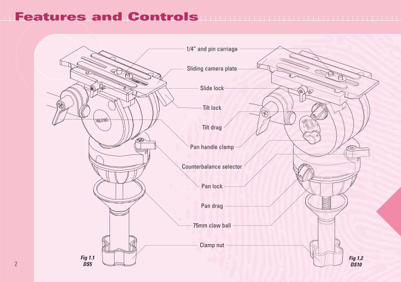
Features and Controls
2Fig 1.1
DS5Fig 1.2DS10
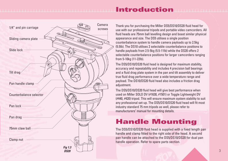
1/4” and pin carriage
Sliding camera plate
Slide lock
Tilt lock
Tilt drag
Pan handle clamp
Counterbalance selector
Pan lock
Pan drag
75mm claw ball
Clamp nut
Introduction
Thank you for purchasing the Miller DS5/DS10/DS20 fluid head foruse with our professional tripods and portable video camcorders. Allfluid heads are 75mm ball levelling design and boast similar physicalappearance and size. The DS5 utilises a single positioncounterbalance system to handle camera payloads up to 2.5kg(5.5lb). The DS10 utilises 2 selectable counterbalance positions tohandle payloads from 2.5-5kg (5.5-11lb) while the DS20 offers 2selectable counterbalance positions for larger camcorders rangingfrom 5-10kg (11-22lb).The DS5/DS10/DS20 fluid head is designed for maximum stability,accuracy and repeatability and includes 4 precision ball bearingsand a fluid drag plate system in the pan and tilt assembly to delivertrue fluid drag performance over a wide temperature range andpayload. The DS10/DS20 fluid head also includes a friction dragadjustment.The DS5/DS10/DS20 fluid head will give best performance whenused on Miller SOLO DV (#1630, #1501) or Toggle Lightweight DV(#440, #420) tripod. This will ensure maximum system stability to suitany professional set-up. The DS5/DS10/DS20 fluid head will fit mostindustry standard 75 mm tripods as well, please refer tomanufacturers’ manual for mounting details.
Handle MountingThe DS5/DS10/DS20 fluid head is supplied with a fixed length panhandle and clamp fitted to the right side of the head. A secondpan handle can be attached to the DS5/DS10/DS20 for dual panhandle operation. Refer to spare parts section.
3
1/4” and pin carriage
Sliding camera plate
Slide lock
Tilt drag
Pan handle clamp
Counterbalance selector
Pan lock
Pan drag
75mm claw ball
Clamp nut
Camerascrews
Fig 1.3DS20
4
Before using please read the following operating instructions. Do not omit any step. N.B. The safe operation of this piece ofprofessional equipment is the responsibility of the operator.
1.1 Loosen the PAN HANDLE CLAMP fully, then rotate the PANHANDLE until it is approximately perpendicular to theTHREADED STUD and tighten the PAN HANDLE CLAMP -avoid contact wear between the serrations on the FluidHead and the PAN HANDLE CLAMP, if this occurs thenunwind the PAN HANDLE CLAMP further.
1.2 Ensure that the TRIPOD BOWL is approximately horizontal.Place the Fluid Head into the TRIPOD BOWL, adjust theBUBBLE LEVEL such that the bubble is inside the blackcircle and tighten the CLAMP NUT.
1.4 Note: If adjusting the level with your camera mounted,first ensure the camera is securely held before looseningCLAMP NUT.
Please note that the best camera control can be achieved bybalancing camera centre of gravity (C of G) over centre axis ofthe head, and by selecting the appropriate counterbalanceposition to suit the weight of the camcorder payload.The DS5/DS10/DS20 is equipped with a sliding camera plate anda removable 1/4”-pin carriage which is standard mounting for DVand MiniDV camcorders. The DS20 is also fitted with a 3/8” &1/4” screws which is standard mounting for DVCAM (see Fig1.3).
The 3/8” & 1/4” screws also allow the DS20 to attach to aproprietary Quick Release Tripod Adaptor or “tripod base plate”such as the Sony VCT-14 or Panasonic SHAN-TM700.2.1 Lock PAN and TILT LOCKS (rotate both levers clockwise until
firm).2.2 Remove CAMERA PLATE from CAMERA PLATFORM by
unlocking the SLIDE LOCK, pushing SAFETY TAB and slidingthe CAMERA PLATE rearward
2.3 With accessories and battery fitted to the camera, it isrecommended to estimate the camera’s Centre of Gravity (Cof G) for the purpose of correctly positioning the camera onthe CAMERA PLATE. The camera’s C of G can be estimated byplacing the camera on to a round rod and then shifting itbackwards or forwards until a balance point – C of G - isachieved. It is recommended to identify this point as it will beuseful in step 2.5.
2.4 Refer to the Camera’s owners manual for correct method ofattachment to the CAMERA PLATE. Attach the camera or theQuick Release Tripod Adaptor to the CAMERA PLATE andsecurely tighten the screws.
2.5 Check that the SLIDE LOCK is loose, then align theCAMERA PLATE with the CAMERA PLATFORM andslide it forward until the safety mechanism is engaged.Then, slide the CAMERA PLATE so that the camera’s C of Gis directly above the centre axis of the Fluid Head and tightenthe SLIDE LOCK. If this can not be achieved then repositionthe camera or the Quick Release Tripod Adaptor on theSLIDING PLATE – step 2.4. This will ensure that the systemhas maximum stability.
2. Camera Set-up
Operating Instructions
1. Fluid Head Set-up
The counterbalance system was designed to neutralise the effectof the camera weight when it is tilted. The DS10 & DS20 FluidHead offers a 2 position counterbalance system which can beoperated via the COUNTERBALANCE SELECTOR (Fig. 2 & 3). TheDS5 Fluid Head has a single position Counterbalance system andis preset. The COUNTERBALANCE SELECTOR must be operatedwhen the SLIDING PLATFORM is in a horizontal position. Afterchanging the Counterbalance setting it may be necessary to tiltthe camera back and forth to ensure that the CB spring hasengaged. The camera must be held securely while changing theCounterbalance setting.3.1 For safety ensure that Counterbalance position 2 is selected.3.2 Hold the camera and release the TILT LOCK, then gently tilt
the camera from a horizontal position forward then backwardand observe its response. If the Camera 'Springs Back' to thehorizontal position then selectCounterbalance position 1.Correct Counterbalancesetting has been achievedwhen minimum effort isrequired to move the cameraover the entire tilt range.
TIP Fine tuning can be achievedby adjusting the SLIDINGPLATFORM - see step 2.5.
The DS5/DS10/DS20 Fluid Head offers highcapacity calliper disc brake system to hold theFluid Head in a fixed pan and/or tilt position.Camera position will not change when applying orreleasing the Pan / Tilt locks.◗ Do not pan or tilt the Fluid Head whilst the PAN or the TILT LOCK
is partially applied.
5
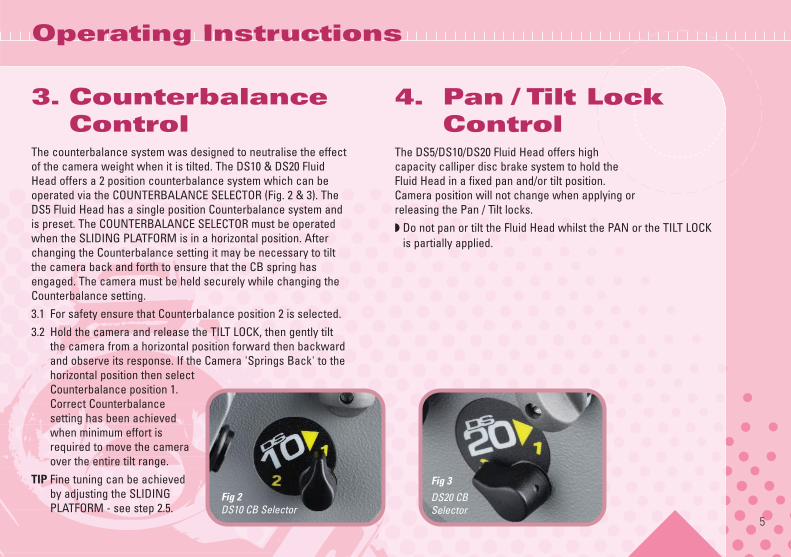
Fig 2DS10 CB Selector
Fig 3
DS20 CB Selector
Operating Instructions
3. CounterbalanceControl
4. Pan / Tilt LockControl
6
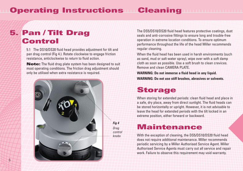
5.1 The DS10/DS20 fluid head provides adjustment for tilt andpan drag control (Fig 4.). Rotate clockwise to engage frictionresistance, anticlockwise to return to fluid action.Note: The fluid drag plate system has been designed to suitmost operating conditions. The friction drag adjustment shouldonly be utilised when extra resistance is required.
The DS5/DS10/DS20 fluid head features protective coatings, dustseals and anti-corrosive fittings to ensure long and trouble-freeoperation in extreme location conditions. To ensure optimumperformance throughout the life of the head Miller recommendsregular cleaning.When the fluid head has been used in harsh environments (suchas sand, mud or salt water spray), wipe over with a soft dampcloth as soon as possible. Use a soft brush to clean crevices.Remove and clean CAMERA PLATE.WARNING: Do not immerse a fluid head in any liquid.WARNING: Do not use stiff brushes, abrasives or solvents.
StorageWhen storing for extended periods: clean fluid head and place ina safe, dry place, away from direct sunlight. The fluid heads canbe stored horizontally or upright. However, it is not advisable toleave the head for extended periods with the tilt locked in anextreme position, either forward or backward.
MaintenanceWith the exception of cleaning, the DS5/DS10/DS20 fluid headdoes not require additional maintenance. Miller recommendsperiodic servicing by a Miller Authorised Service Agent. MillerAuthorised Service Agents must carry out all service and repairwork. Failure to observe this requirement may void warranty.
Cleaning
Fig 4
Dragcontrolknobs
Operating Instructions
5. Pan / Tilt DragControl
7
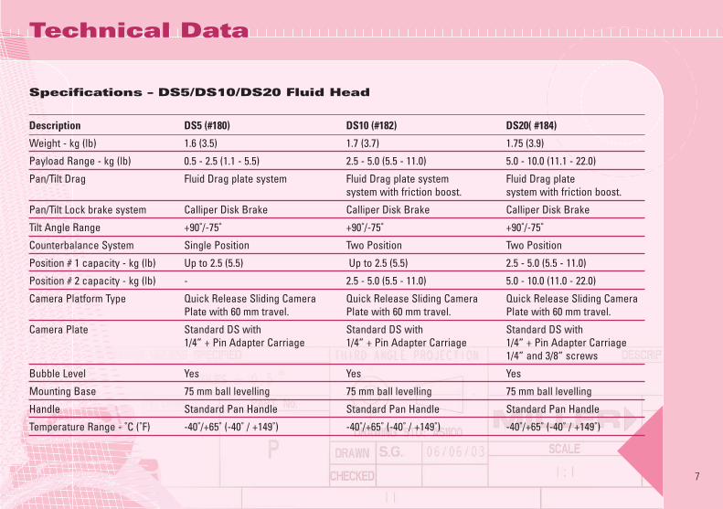
Specifications – DS5/DS10/DS20 Fluid Head
Description DS5 (#180) DS10 (#182) DS20( #184)
Weight - kg (lb) 1.6 (3.5) 1.7 (3.7) 1.75 (3.9)
Payload Range - kg (lb) 0.5 - 2.5 (1.1 - 5.5) 2.5 - 5.0 (5.5 - 11.0) 5.0 - 10.0 (11.1 - 22.0)
Pan/Tilt Drag Fluid Drag plate system Fluid Drag plate system Fluid Drag plate system with friction boost. system with friction boost.
Pan/Tilt Lock brake system Calliper Disk Brake Calliper Disk Brake Calliper Disk Brake
Tilt Angle Range +90˚/-75˚ +90˚/-75˚ +90˚/-75˚
Counterbalance System Single Position Two Position Two Position
Position # 1 capacity - kg (lb) Up to 2.5 (5.5) Up to 2.5 (5.5) 2.5 - 5.0 (5.5 - 11.0)
Position # 2 capacity - kg (lb) - 2.5 - 5.0 (5.5 - 11.0) 5.0 - 10.0 (11.0 - 22.0)
Camera Platform Type Quick Release Sliding Camera Quick Release Sliding Camera Quick Release Sliding CameraPlate with 60 mm travel. Plate with 60 mm travel. Plate with 60 mm travel.
Camera Plate Standard DS with Standard DS with Standard DS with1/4” + Pin Adapter Carriage 1/4” + Pin Adapter Carriage 1/4” + Pin Adapter Carriage
1/4” and 3/8” screws
Bubble Level Yes Yes Yes
Mounting Base 75 mm ball levelling 75 mm ball levelling 75 mm ball levelling
Handle Standard Pan Handle Standard Pan Handle Standard Pan Handle
Temperature Range - ˚C (˚F) -40˚/+65˚ (-40˚ / +149˚) -40˚/+65˚ (-40˚ / +149˚) -40˚/+65˚ (-40˚ / +149˚)
Technical Data
MILLER CAMERA SUPPORT (Australia)30 Hotham Parade, Artarmon, SydneyNSW 2064 AustraliaTel: +61 2 9439 6377Fax: +61 2 9438 2819Email: [email protected]
MILLER FLUID HEADS (Europe) LTD.Unit A2, Ford Lane Industrial EstateFord Lane, Ford, West SussexBN18 0DF United KingdomTel: +44 (0)1243 555 255Fax: +44(0)1243 555 001Email: [email protected]
MILLER CAMERA SUPPORT LLC (USA)216 Little Falls Road, Cedar GroveNew Jersey 07009-1231 USATel: (973) 857 8300Fax: (973) 857 8188Email: [email protected]
MILLER TRIPODS Canada1055 Granville StreetVancouver BC V6Z1L4, CanadaTel: (604) 685 4654 Fax: (604) 685 5648Email: [email protected]
D3573 - 2 09/06
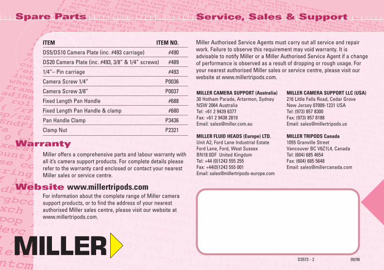
ITEM ITEM NO.
DS5/DS10 Camera Plate (inc. #493 carriage) #490
DS20 Camera Plate (inc. #493, 3/8” & 1/4” screws) #489
1/4”– Pin carriage #493
Camera Screw 1/4” P0036
Camera Screw 3/8” P0037
Fixed Length Pan Handle #688
Fixed Length Pan Handle & clamp #680
Pan Handle Clamp P3436
Clamp Nut P2321
WarrantyMiller offers a comprehensive parts and labour warranty withall it’s camera support products. For complete details pleaserefer to the warranty card enclosed or contact your nearestMiller sales or service centre.
Website www.millertripods.comFor information about the complete range of Miller camerasupport products, or to find the address of your nearestauthorised Miller sales centre, please visit our website atwww.millertripods.com.
Service, Sales & Support
Miller Authorised Service Agents must carry out all service and repairwork. Failure to observe this requirement may void warranty. It isadvisable to notify Miller or a Miller Authorised Service Agent if a changeof performance is observed as a result of dropping or rough usage. Foryour nearest authorised Miller sales or service centre, please visit ourwebsite at www.millertripods.com.
Spare Parts