Embed Size (px)
Citation preview

Driving valueSophisticated ring-geared mill drives from ABB
Reprint from ABB Review, 1&2/2011
The latest generation of ABB medium-voltage frequency converters provides excellent opportunities to improve the grinding process used in the minerals industry. The development of several dedicated and advanced operational functions for the ring-geared grinding mills, ensures smooth, safe and reliable operation with minimum stress on mechanical equipment and highest possible availability of the mills.

2 Driving value | Reprint from ABB review 1&2/2011
The latest generation of ABB medium-voltage frequency converters provides excellent opportunities to improve the grinding process used in the minerals industry. The development of several dedicated and advanced operational functions for the ring-geared grinding mills, ensures smooth, safe and reliable operation with minimum stress on mechanical equipment and highest possible availability of the mills.
avoid rough starts and torque spikes, in particular in larger mills. During all op-eration conditions (i.e., starting, normal grinding operation, stopping) a mechani-cally friendly system is required.
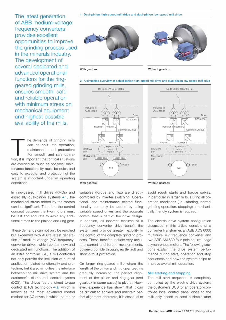
The electric drive system configuration discussed in this article consists of a converter transformer, an ABB ACS 6000 multidrive MV frequency converter and two ABB AMI630 four-pole squirrel-cage asynchronous motors. The following sec-tions explain the drive system perfor-mance during start, operation and stop sequences and how the system helps to improve overall mill operation.
Mill starting and stopping The mill start sequence is completely controlled by the electric drive system; the customer’s DCS (or an operator-con-trolled local control panel close to the mill) only needs to send a simple start
variables (torque and flux) are directly controlled by inverter switching. Opera-tional- and maintenance related func-tionality can only be added by using variable speed drives and the accurate control that is part of the drive design. In addition, all inherent features of a frequency converter drive benefit the system and provide greater flexibility in the control of the complete grinding pro-cess. These benefits include very accu-rate current and torque measurements, power-drop ride through, earth-fault and short-circuit protection.
On larger ring-geared mills where the length of the pinion and ring-gear teeth is gradually increasing, the perfect align-ment of the pinion and ring gear (and gearbox in some cases) is pivotal. How-ever, experience has shown that it can be difficult to achieve and maintain per-fect alignment; therefore, it is essential to
T he demands of grinding mills can be split into operation, maintenance and protection: For smooth and safe opera-
tion, it is important that critical situations are avoided as much as possible; main-tenance functionality must be quick and easy to execute; and protection of the system is important under all operating conditions.
In ring-geared mill drives (RMDs) and especially dual-pinion systems ➔ 1, the mechanical stress added by the motors can be significant. Therefore the control concept between the two motors must be fast and accurate to avoid any addi-tional stress to the pinions and ring gear.
These demands can not only be reached but exceeded with ABB’s latest genera-tion of medium-voltage (MV) frequency-converter drives, which contain new and dedicated mill functions. The addition of an extra controller (i.e., a mill controller) not only permits the inclusion of a lot of application related functionality and pro-tection, but it also simplifies the interface between the mill drive system and the customer’s distributed control system (DCS). The drives feature direct torque control (DTC) technology ➔ 2, which is known as the most advanced control method for AC drives in which the motor
1 Dual-pinion high-speed mill drive and dual-pinion low-speed mill drive
With gearbox Without gearbox
2 A simplified overview of a dual-pinion high-speed mill drive and dual-pinion low-speed mill drive
With gearbox Without gearbox
Up to 36 kV, 50 or 60 Hz Up to 36 kV, 50 or 60 Hz
Included in ABB scope
Included in ABB scope
Rectifier 1 Rectifier 1
Inverter 1 Inverter 1
Electrical part
Electrical part
Asynchro-nous
motors
Synchro-nous
motors
Gear box Gear box
Pinion Pinion
Mechanical part
Mechanical part
Inverter 2 Inverter 2
Rectifier 2 Rectifier 2
ACS 6000 ACS 6000
Common DC bus Common DC bus
AC
DC
AC
DC
DC
AC
DC
AC
DC
AC
DC
AC
AC
DC
AC
DC
Mill Mill
Drive Drive
Reprint from ABB review 1&2/2011 | Driving value 3
4 Driving value | Reprint from ABB review 1&2/2011
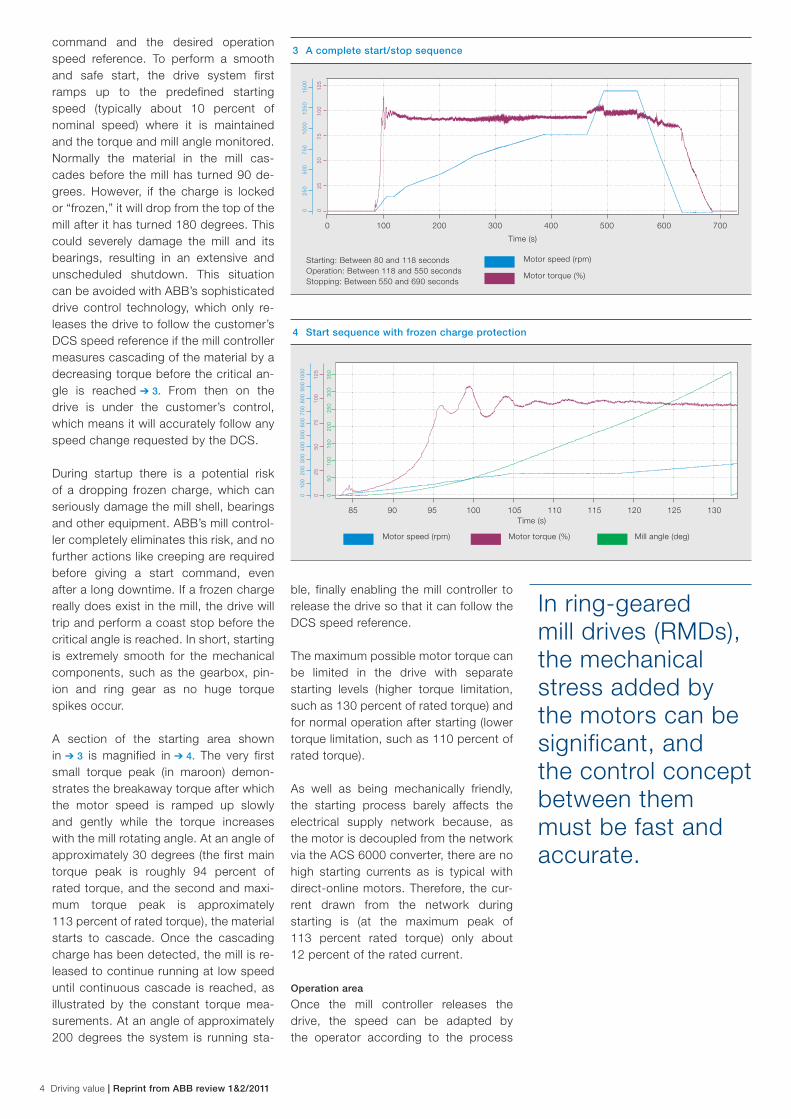
command and the desired operation speed reference. To perform a smooth and safe start, the drive system first ramps up to the predefined starting speed (typically about 10 percent of nominal speed) where it is maintained and the torque and mill angle monitored. Normally the material in the mill cas-cades before the mill has turned 90 de-grees. However, if the charge is locked or “frozen,” it will drop from the top of the mill after it has turned 180 degrees. This could severely damage the mill and its bearings, resulting in an extensive and unscheduled shutdown. This situation can be avoided with ABB’s sophisticated drive control technology, which only re-leases the drive to follow the customer’s DCS speed reference if the mill controller measures cascading of the material by a decreasing torque before the critical an-gle is reached ➔ 3. From then on the drive is under the customer’s control, which means it will accurately follow any speed change requested by the DCS.
During startup there is a potential risk of a dropping frozen charge, which can seriously damage the mill shell, bearings and other equipment. ABB’s mill control-ler completely eliminates this risk, and no further actions like creeping are required before giving a start command, even after a long downtime. If a frozen charge really does exist in the mill, the drive will trip and perform a coast stop before the critical angle is reached. In short, starting is extremely smooth for the mechanical components, such as the gearbox, pin-ion and ring gear as no huge torque spikes occur.
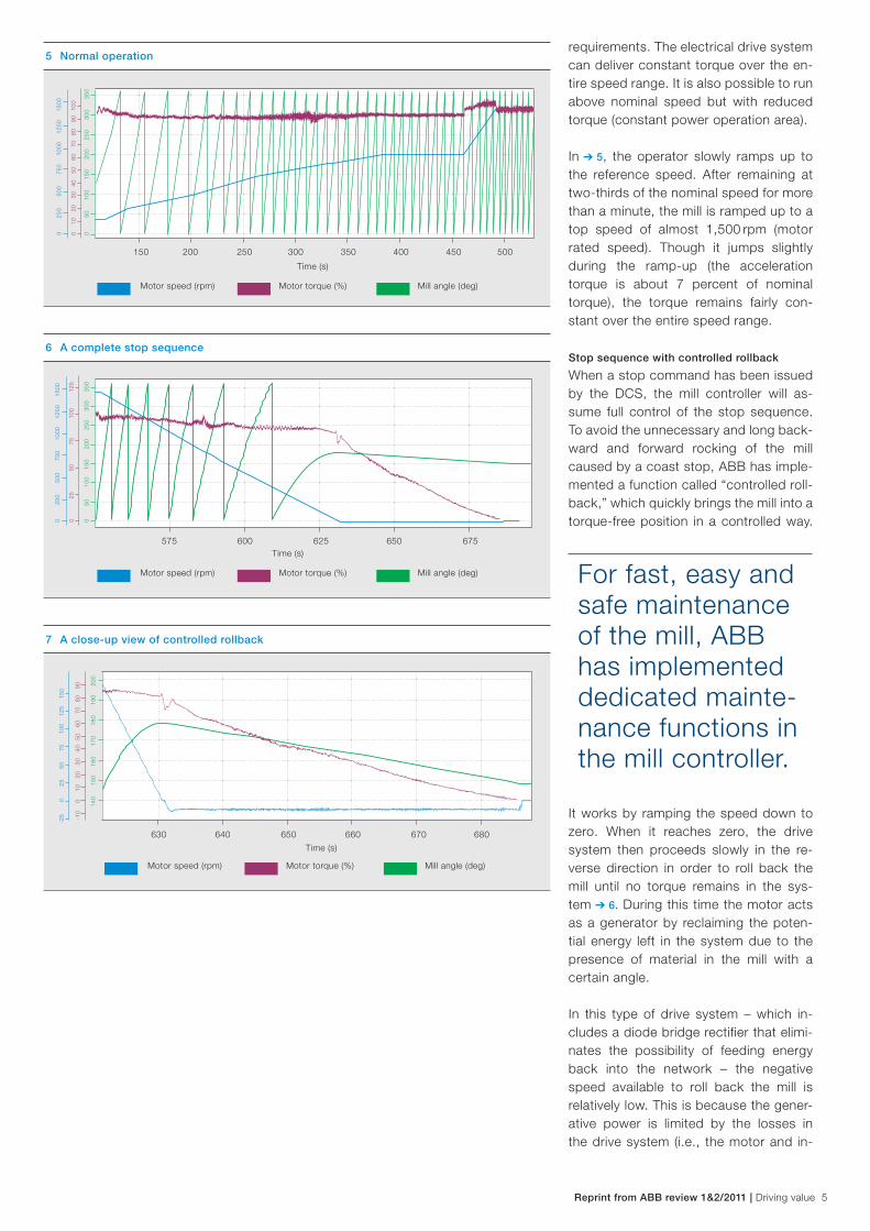
A section of the starting area shown in ➔ 3 is magnified in ➔ 4. The very first small torque peak (in maroon) demon-strates the breakaway torque after which the motor speed is ramped up slowly and gently while the torque increases with the mill rotating angle. At an angle of approximately 30 degrees (the first main torque peak is roughly 94 percent of rated torque, and the second and maxi-mum torque peak is approximately 113 percent of rated torque), the material starts to cascade. Once the cascading charge has been detected, the mill is re-leased to continue running at low speed until continuous cascade is reached, as illustrated by the constant torque mea-surements. At an angle of approximately 200 degrees the system is running sta-
ble, finally enabling the mill controller to release the drive so that it can follow the DCS speed reference.
The maximum possible motor torque can be limited in the drive with separate starting levels (higher torque limitation, such as 130 percent of rated torque) and for normal operation after starting (lower torque limitation, such as 110 percent of rated torque).
As well as being mechanically friendly, the starting process barely affects the electrical supply network because, as the motor is decoupled from the network via the ACS 6000 converter, there are no high starting currents as is typical with direct-online motors. Therefore, the cur-rent drawn from the network during starting is (at the maximum peak of 113 percent rated torque) only about 12 percent of the rated current.
Operation area
Once the mill controller releases the drive, the speed can be adapted by the operator according to the process
In ring-geared mill drives (RMDs), the mechanical stress added by the motors can be significant, and the control concept between them must be fast and accurate.
3 A complete start/stop sequence
Starting: Between 80 and 118 seconds Operation: Between 118 and 550 seconds Stopping: Between 550 and 690 seconds
Time (s)
0
25
50
75
100
125
0
250
500
750
1000
12
50
1500
0 100 200 300 400 500 600 700
Motor speed (rpm)
Motor torque (%)
4 Start sequence with frozen charge protection
85 90 95 100 105 110 115 120 125 130
0
50
100
150
200
250
300
350
0
100
200
300
400
500
600
700
800
900
1000
0
25
50
75
100
125
Time (s)
Motor speed (rpm) Motor torque (%) Mill angle (deg)
Reprint from ABB review 1&2/2011 | Driving value 5
requirements. The electrical drive system can deliver constant torque over the en-tire speed range. It is also possible to run above nominal speed but with reduced torque (constant power operation area).
In ➔ 5, the operator slowly ramps up to the reference speed. After remaining at two-thirds of the nominal speed for more than a minute, the mill is ramped up to a top speed of almost 1,500 rpm (motor rated speed). Though it jumps slightly during the ramp-up (the acceleration torque is about 7 percent of nominal torque), the torque remains fairly con-stant over the entire speed range.
Stop sequence with controlled rollback
When a stop command has been issued by the DCS, the mill controller will as-sume full control of the stop sequence. To avoid the unnecessary and long back-ward and forward rocking of the mill caused by a coast stop, ABB has imple-mented a function called “controlled roll-back,” which quickly brings the mill into a torque-free position in a controlled way.
It works by ramping the speed down to zero. When it reaches zero, the drive system then proceeds slowly in the re-verse direction in order to roll back the mill until no torque remains in the sys-tem ➔ 6. During this time the motor acts as a generator by reclaiming the poten-tial energy left in the system due to the presence of material in the mill with a certain angle.
In this type of drive system – which in-cludes a diode bridge rectifier that elimi-nates the possibility of feeding energy back into the network – the negative speed available to roll back the mill is relatively low. This is because the gener-ative power is limited by the losses in the drive system (i.e., the motor and in-
For fast, easy and safe maintenance of the mill, ABB has implemented dedicated mainte-nance functions in the mill controller.
6 A complete stop sequence
575 600 625 650 675
0
50
100
150
200
250
300
350
0
250
500
750
1000
12
50
1500
Time (s)
Motor speed (rpm) Motor torque (%) Mill angle (deg)
0
25
50
75
100
125
7 A close-up view of controlled rollback
630 640 650 660 670 680
140
150
160
170
180
190
200
-25
0 25
50
75
10
0 12
5 15
0
Time (s)
Motor speed (rpm) Motor torque (%) Mill angle (deg)
-10
0
10
20
30
40
50
60
70
80
90
5 Normal operation
150 200 250 300 350 400 450 500
0
50
100
150
200
250
300
350
0 25
0 50
0 75
0 10
00
1250
15
00
0
10
20
30
40
50
60
70
80
90
100
Time (s)
Motor speed (rpm) Motor torque (%) Mill angle (deg)

6 Driving value | Reprint from ABB review 1&2/2011
verter/DC link of the frequency convert-er). ABB also offers the option of a truly four-quadrant drive system with an ac-tive rectifier unit, which enables braking energy to be fed back into the network. This option significantly reduces the time required to roll back the mill.
A close-up of the controlled rollback area (from ➔ 6) is shown in ➔ 7. When the mill speed has been ramped down and the mill is in an unbalanced position, the motor first creates a positive torque that just about holds the mill with the charge unbalanced. Slightly reducing the torque changes the direction of rotation, which then causes the mill to gently roll back until the charge is balanced. The data in ➔ 7 clearly show that the torque (ap-plied to the pinion teeth) is always positive during the complete procedure, meaning there can be no backlash between the pinion and ring gear, and contact between the two is always maintained. If backlash were to happen, it would be shown by a drop in torque to zero or below.
In this particular configuration, the motor speed during controlled rollback is only 12.8 rpm, which is about 0.85 percent of nominal speed! In other words, the mill is smoothly rolled back in a controlled manner at a speed of about 0.1 rpm. Even at this very low speed, the system still runs stable thanks to ABB’s ad-vanced DTC technology. In addition, the time between reaching zero speed and zero torque (i.e., mill stopped and no overshooting) takes about 55 seconds.
While this is significantly faster than a coast stop, the use of a converter setup with four quadrant capabilities would re-duce this figure even further.
The latest genera-tion of ABB MV frequency convert-ers provides excel-lent opportunities to improve the grinding process used in the miner-als industry.
By looking at the angle curve (in ➔ 7), it can be observed that the mill was rolled back by 30 degrees, from about 178 degrees to approximately 148 degrees (i.e., the angle curve decreases once the mill speed becomes negative at approxi-mately 630 seconds). This matches per-fectly with the measured cascading angle during the startup in ➔ 4.
Coast stop (rocking mill)To fully appreciate the distinct benefits of variable speed operation and therefore controlled rollback, a coast stop from nominal speed was tested on the same mill. The test showed that the time taken for the mill to reach a complete stand-still, (i.e., when the backward and for-ward rocking of the mill had ceased) after the “stop” command was received was about 180 seconds ➔ 8.
On closer inspection of the motor speed signal (measured by a tachometer on the motor) in ➔ 9, there is evidence of back-lash (shown by the arrows) between the teeth of the pinion and the ring gear. The cause of this is as follows: The ring gear drives the motor, which has to be accel-
8 A coast stop (rocking mill)
Time (s)
-50
0 50
10
0 15
0 20
0
475 500 525 550 575 600 625 650
-250
0
250
500
750
1000
125
0 15
00
Motor speed (rpm) Mill angle (deg)
Time (s)
525.0 257.5 530.0 532.5 535.0 537.5 540.0 542.5 545.0
Motor speed (rpm)
9 Backlash during a coast stop-2
00
-150
-1
00
-50
0 50
10
0 15
0 20
0
erated and decelerated due to its inertia. During the deceleration process, the tooth of the ring gear hits the tooth of the pinion several times to break the motor speed. Not only does this cause back-lash, but it also severely stresses the gear teeth.
Maintenance functionsFor fast, easy and safe maintenance of the mill, ABB has implemented dedi-cated maintenance functions in the mill controller.
Creeping
Creeping, a common maintenance func-tion for mills, is nothing more than turn-ing the mill at very low speeds for main-tenance purposes, such as the visual inspection of bearings or manual posi-tioning for a liner change. In general mills using fixed-speed motors for the main drive system need an auxiliary motor with a reduction gearbox to perform creeping. ABB’s mill drive systems can provide high torque at low speed, there-by ensuring creeping is possible with the main drive.

Reprint from ABB review 1&2/2011 | Driving value 7
verter/DC link of the frequency convert-er). ABB also offers the option of a truly four-quadrant drive system with an ac-tive rectifier unit, which enables braking energy to be fed back into the network. This option significantly reduces the time required to roll back the mill.
A close-up of the controlled rollback area (from ➔ 6) is shown in ➔ 7. When the mill speed has been ramped down and the mill is in an unbalanced position, the motor first creates a positive torque that just about holds the mill with the charge unbalanced. Slightly reducing the torque changes the direction of rotation, which then causes the mill to gently roll back until the charge is balanced. The data in ➔ 7 clearly show that the torque (ap-plied to the pinion teeth) is always positive during the complete procedure, meaning there can be no backlash between the pinion and ring gear, and contact between the two is always maintained. If backlash were to happen, it would be shown by a drop in torque to zero or below.
In this particular configuration, the motor speed during controlled rollback is only 12.8 rpm, which is about 0.85 percent of nominal speed! In other words, the mill is smoothly rolled back in a controlled manner at a speed of about 0.1 rpm. Even at this very low speed, the system still runs stable thanks to ABB’s ad-vanced DTC technology. In addition, the time between reaching zero speed and zero torque (i.e., mill stopped and no overshooting) takes about 55 seconds.
While this is significantly faster than a coast stop, the use of a converter setup with four quadrant capabilities would re-duce this figure even further.
The latest genera-tion of ABB MV frequency convert-ers provides excel-lent opportunities to improve the grinding process used in the miner-als industry.
By looking at the angle curve (in ➔ 7), it can be observed that the mill was rolled back by 30 degrees, from about 178 degrees to approximately 148 degrees (i.e., the angle curve decreases once the mill speed becomes negative at approxi-mately 630 seconds). This matches per-fectly with the measured cascading angle during the startup in ➔ 4.
Coast stop (rocking mill)To fully appreciate the distinct benefits of variable speed operation and therefore controlled rollback, a coast stop from nominal speed was tested on the same mill. The test showed that the time taken for the mill to reach a complete stand-still, (i.e., when the backward and for-ward rocking of the mill had ceased) after the “stop” command was received was about 180 seconds ➔ 8.
On closer inspection of the motor speed signal (measured by a tachometer on the motor) in ➔ 9, there is evidence of back-lash (shown by the arrows) between the teeth of the pinion and the ring gear. The cause of this is as follows: The ring gear drives the motor, which has to be accel-
8 A coast stop (rocking mill)
Time (s)
-50
0 50
10
0 15
0 20
0
475 500 525 550 575 600 625 650
-250
0
250
500
750
1000
125
0 15
00
Motor speed (rpm) Mill angle (deg)
Time (s)
525.0 257.5 530.0 532.5 535.0 537.5 540.0 542.5 545.0
Motor speed (rpm)
9 Backlash during a coast stop
-200
-1
50
-100
-5
0 0
50
100
150
200
erated and decelerated due to its inertia. During the deceleration process, the tooth of the ring gear hits the tooth of the pinion several times to break the motor speed. Not only does this cause back-lash, but it also severely stresses the gear teeth.
Maintenance functionsFor fast, easy and safe maintenance of the mill, ABB has implemented dedi-cated maintenance functions in the mill controller.
Creeping
Creeping, a common maintenance func-tion for mills, is nothing more than turn-ing the mill at very low speeds for main-tenance purposes, such as the visual inspection of bearings or manual posi-tioning for a liner change. In general mills using fixed-speed motors for the main drive system need an auxiliary motor with a reduction gearbox to perform creeping. ABB’s mill drive systems can provide high torque at low speed, there-by ensuring creeping is possible with the main drive.
Automatic positioning sequence
The automatic positioning function al-lows operators to accurately turn the mill by any desired angle or number of liner rows. In fact it is a very helpful function during liner replacement because it helps to reduce downtime and increase avail-ability. Initiated by a local control panel or the DCS, the operator preselects the positioning mode, direction of rotation and desired angle or number of liners.
An automatic positioning function re-questing a 180 degree turn is illustrated in ➔ 11: The material cascades at 27 de-grees; the drive keeps running at low speed for a certain time before ramping down; at zero speed the mill has turned 209 degrees at which point the torque value is 94 percent of nominal torque (meaning the mill is fully loaded); and the drive then runs in reverse, slowly reduc-ing the torque. By the time the drive stops (101.6 seconds later), the mill has turned 179.2 degrees, which translates into an inaccuracy of only 0.5 percent! The optimum positioning speed for this example was set at 158 rpm, which cor-responds to 10.5 percent (10 percent is typical) of nominal speed. At this speed, the angle inaccuracies were below 1 per-cent for all tests.
Deformation protection
Deformation protection is an automatic positioning sequence with a fixed angle reference of 180 degrees. Even if defor-mation is not a real problem for grinding mills in the minerals industry, the function can still be used during longer mill stops (e.g., maintenance) to prevent a frozen charge from occurring. Operators need only preselect a deformation protection mode and the preferred direction of rota-tion before issuing a start command. The mill controller then takes care of the 180 degree turn in exactly the same way as that illustrated in ➔ 11.
Frozen charge remover
Frozen charges have been known to occur mostly on ball mills. After one has been detected, the frozen material needs to be removed; this is normally done manually and can result in significant downtime.
ABB’s dedicated mill functionality not only protects the mill from a dropping fro-zen charge, but it also offers a patented function called frozen charge remover, which is available in the mill controller
The automatic positioning function allows operators to accurately turn the mill by any desired angle or number of liner rows.
11 Automatic positioning routine with 180 degree angle reference
470 480 490 500 510 520 530 540 550 560
0 50
10
0 15
0 20
0
-25
0 25
50
75
10
0 12
5 15
0 17
5
Time (s)
Motor speed (rpm) Motor torque (%) Mill angle (deg)
0 25
50
75
10
0
10 A creeping routine
-50
0
50
100
150
200
250
300
350
Motor speed (rpm) Motor torque (%) Mill angle (deg)
100 150 200 250 300Time (s)
-25
0 25
50
75
10
0
-25
0 25
50
75
10
0
Preferably, the creeping command should be initiated from a local control panel close to the mill, but it can also be acti-vated remotely from the DCS. The start procedure is completely controlled by the mill controller and frozen charge pro-tection is activated when creeping mode is selected. Creeping speed is typically 5 percent of nominal speed but can be adjusted to between 1 and 10 percent after a successful start.
A complete creeping sequence is shown in ➔ 10. The creeping speed is set at 48 rpm or 3.2 percent of nominal speed; cascading is detected at a mill angle of 23.5 degrees and a torque of 73 per- cent of nominal torque. The operator keeps the mill running at this speed for 420 degrees before initiating a stop command, causing the mill controller to ramp down the speed and perform a controlled rollback until there is no torque remaining in the system before stopping the drive.

8 Driving value | Reprint from ABB review 1&2/2011
and operation takes place in the same (i.e., first) quadrant, no backlash phe-nomenon can occur between the pinions and ring gear.
ABB’s dedicated mill functions are ca-pable of adding significant value to grind-ing mills in terms of efficient operation and maintenance. But this drive system is also available for dual pinion mill drives, i.e., when two motors are mechanically connected via the mill ring gear and operating together to turn the mill. This obviously requires accurate load sharing.
In ring-geared mill drives (RMDs) and es-pecially dual-pinion systems, the me-chanical stress added by the motors can be significant. Therefore the control con-cept between the two motors must be fast and accurate to avoid any additional stress to the pinions and ring gear.
Thanks to the addition of an extra con-troller, ABB’s latest generation of medi-um-voltage (MV) frequency converter drives not only includes several new ap-plication-related functions for the safe and smooth operation of the mill, but it also simplifies the interface between the mill drive system and the customer’s dis-tributed control system (DCS). On the operation side, these functions help im-prove the start, normal grinding opera-tion and stop sequences, while dedicat-ed maintenance and protection functions, such as creeping (turning the mill at very low speeds for inspection), automatic positioning sequencing, deformation protection and frozen-charge remover ensure fast, easy and safe servicing of the mill.
The following section of this article fo-cuses on field measurements taken from the drive system of an installed and com-missioned 2 × 5 MW dual-pinion ring-geared pebble mill ➔ 14. The mine in which the drive system is installed is de-scribed in “A mine of efficiency” on page 56 of ABB Review 2 /11 [3]. In this set-up, the two motors are mechanically con-nected via the mill ring gear and operate together to turn the mill. This mechanism requires very accurate load sharing be-tween the two motors during the start, normal operation and stop sequences.
12 Frozen charge remover with controlled rollback
0 50
10
0 15
0 20
0
Motor speed (rpm) Motor torque (%) Mill angle (deg)
4290 4295 4300 4305 4310 4315 4320 4325 4330 4335 4340 4345
Time (s)
-25
0 25
50
75
-25
0 25
50
75
13 Frozen charge remover torque steps
4290.0 4292.5 4295.0 4297.5 4300.0 4302.5
0
50
100
150
200
250
0 10
20
30
40
50
60
70
80
90
10
0
0 10
20
30
40
50
60
70
Time (s)
Motor speed (rpm) Motor torque (%) Mill angle (deg)
and can only be initiated manually from a local control panel or from the DCS. The frozen charge remover function tries to loosen the material by applying torque steps to the system. The optimal ampli-tude and duration of these steps are found and set during commissioning. The amplitude of the torque steps is defined in a way that adds a certain percentage
of the actual torque to the system, while the protection functions, such as torque and current limits, operate as if the mill was performing under normal conditions. This means the mechanical equipment is never exposed to stress levels exceeding the values that can occur during normal operation. The frozen charge remover
function can be applied in both positive and negative directions.
A complete frozen charge remover se-quence with a positive direction of rota-tion and controlled rollback is shown in ➔ 12 and a close-up of the initial part of the sequence is given in ➔ 13. Torque steps, also reflected by speed
changes, are ap-plied to the system soon after a mill breakaway and are implemented by a sequence of ac-celerating and de-celerating phases, which try to loosen the frozen charge. The amplitude of
the steps is a fixed relative value of the actual torque added to the system and can be adjusted during commis sioning.
With reference to ➔ 13 the maximum amplitude of the biggest torque step is 19.2 percent of nominal torque. Because torque and speed are always positive
ABB’s dedicated mill functions are capable of adding signifi-cant value to grinding mills in terms of efficient operation and maintenance.
Reprint from ABB review 1&2/2011 | Driving value 9
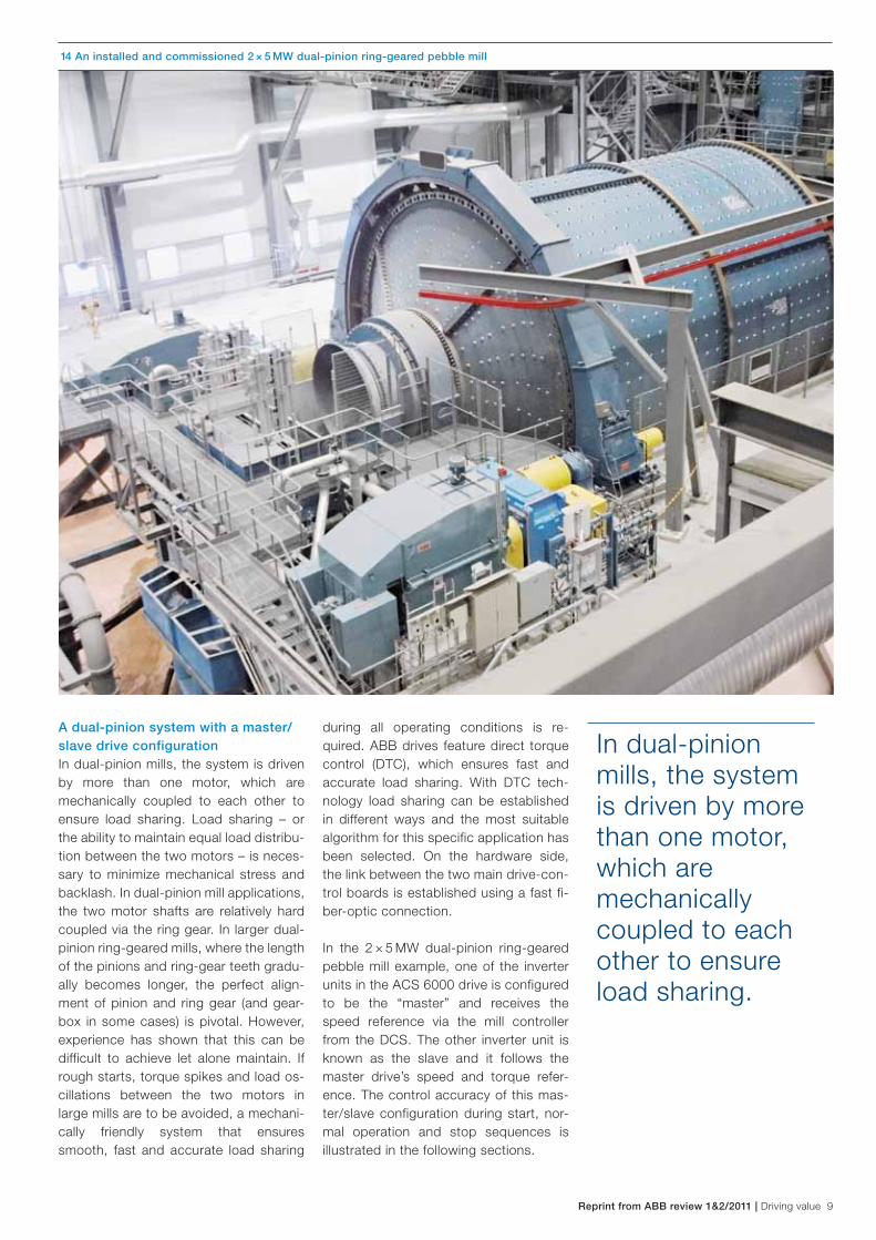
14 An installed and commissioned 2 × 5 MW dual-pinion ring-geared pebble mill
A dual-pinion system with a master/slave drive configurationIn dual-pinion mills, the system is driven by more than one motor, which are mechanically coupled to each other to ensure load sharing. Load sharing – or the ability to maintain equal load distribu-tion between the two motors – is neces-sary to minimize mechanical stress and backlash. In dual-pinion mill appli cations, the two motor shafts are relatively hard coupled via the ring gear. In larger dual-pinion ring-geared mills, where the length of the pinions and ring-gear teeth gradu-ally becomes longer, the perfect align-ment of pinion and ring gear (and gear-box in some cases) is pivotal. However, experience has shown that this can be difficult to achieve let alone maintain. If rough starts, torque spikes and load os-cillations between the two motors in large mills are to be avoided, a mechani-cally friendly system that ensures smooth, fast and accurate load sharing
during all operating conditions is re-quired. ABB drives feature direct torque control (DTC), which ensures fast and accurate load sharing. With DTC tech-nology load sharing can be established in different ways and the most suitable algorithm for this specific application has been selected. On the hardware side, the link between the two main drive-con-trol boards is established using a fast fi-ber-optic connection.
In the 2 × 5 MW dual-pinion ring-geared pebble mill example, one of the inverter units in the ACS 6000 drive is configured to be the “master” and receives the speed reference via the mill controller from the DCS. The other inverter unit is known as the slave and it follows the master drive’s speed and torque refer-ence. The control accuracy of this mas-ter/slave configuration during start, nor-mal operation and stop sequences is illustrated in the following sections.
In dual-pinion mills, the system is driven by more than one motor, which are mechanically coupled to each other to ensure load sharing.
10 Driving value | Reprint from ABB review 1&2/2011
15 Master/slave drive start and stop sequence
Time (seconds)
0
25
50
75
100
125
0
250
500
750
1000
12
50
1500
0 100 200 300 400 500 600 700
Motor speed master (rpm)
Motor speed follower (rpm)
Motor torque master (%)
Motor torque follower (%)
16 A close up of the start sequence
85 90 95 100 105 110 115 120 125 130
0
50
100
150
200
250
300
350
0
100
200
300
400
500
600
700
800
900
1000
0
25
50
75
100
125
Time (seconds)
Motor speed master (rpm)
Motor speed follower (rpm)
Motor torque master (%)
Motor torque follower (%)
Mill angle (Deg)
17 A complete stop sequence using the master/slave drive system
575 600 625 650 675
0
50
100
150
200
250
300
350
0
250
500
750
1000
12
50
1500
Time (seconds)
0
25
50
75
100
125
Motor speed master (rpm)
Motor speed follower (rpm)
Motor torque master (%)
Motor torque follower (%)
Mill angle (Deg)
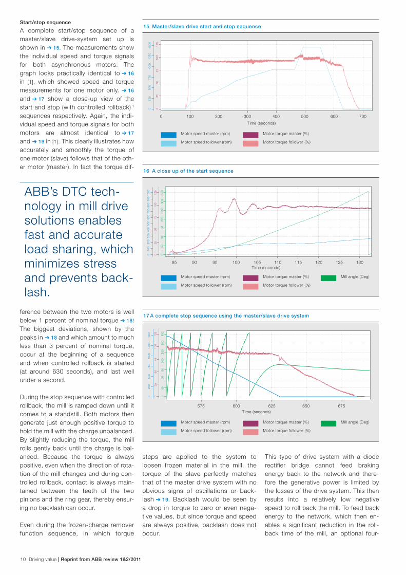
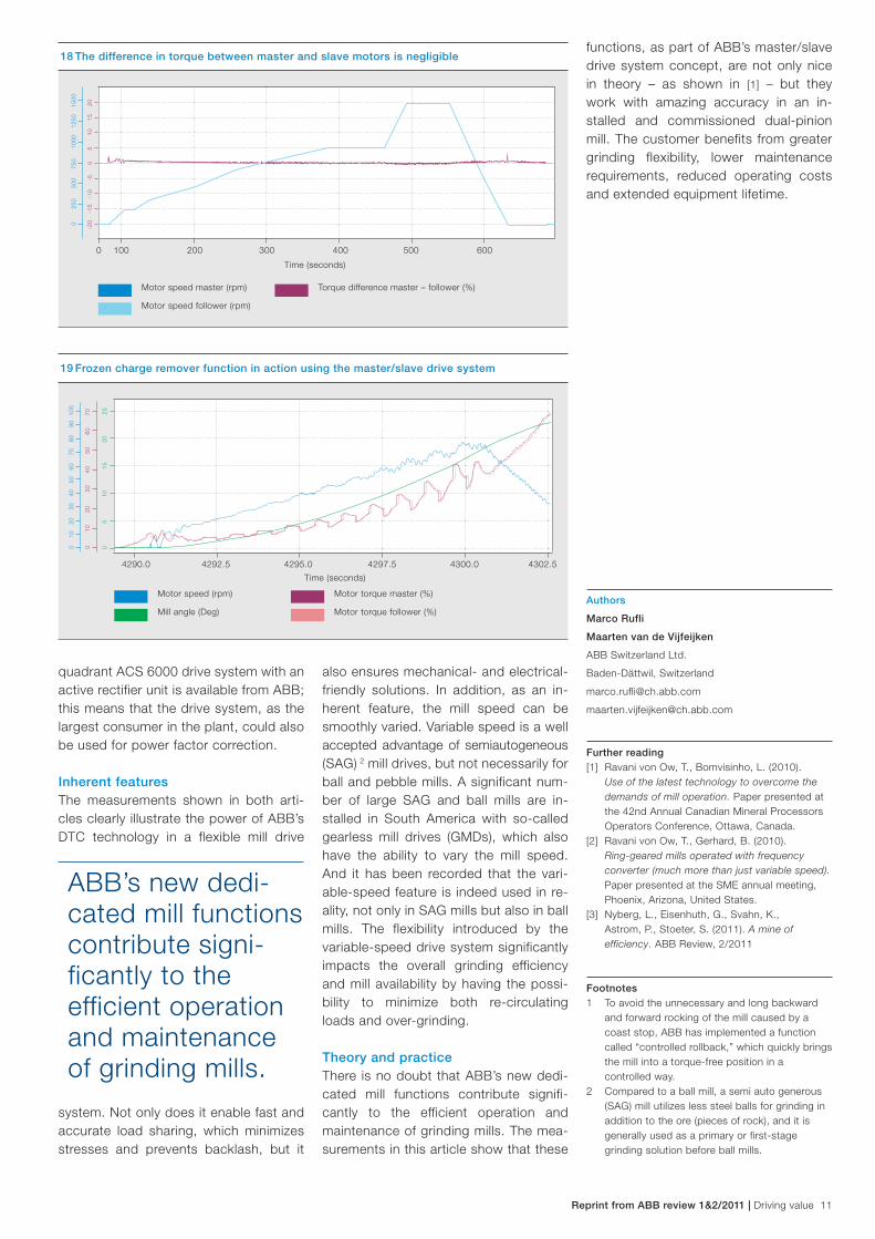
steps are applied to the system to loosen frozen material in the mill, the torque of the slave perfectly matches that of the master drive system with no obvious signs of oscillations or back-lash ➔ 19. Backlash would be seen by a drop in torque to zero or even nega-tive values, but since torque and speed are always positive, backlash does not occur.
Start/stop sequence
A complete start/stop sequence of a master/slave drive-system set up is shown in ➔ 15. The measurements show the individual speed and torque signals for both asynchronous motors. The graph looks practically identical to ➔ 16 in [1], which showed speed and torque measurements for one motor only. ➔ 16
and ➔ 17 show a close-up view of the start and stop (with controlled rollback) 1 sequences respectively. Again, the indi-vidual speed and torque signals for both motors are almost identical to ➔ 17
and ➔ 19 in [1]. This clearly illustrates how accurately and smoothly the torque of one motor (slave) follows that of the oth-er motor (master). In fact the torque dif-
ference between the two motors is well below 1 percent of nominal torque ➔ 18! The biggest deviations, shown by the peaks in ➔ 18 and which amount to much less than 3 percent of nominal torque, occur at the beginning of a sequence and when controlled rollback is started (at around 630 seconds), and last well under a second.
During the stop sequence with controlled rollback, the mill is ramped down until it comes to a standstill. Both motors then generate just enough positive torque to hold the mill with the charge unbalanced. By slightly reducing the torque, the mill rolls gently back until the charge is bal-anced. Because the torque is always positive, even when the direction of rota-tion of the mill changes and during con-trolled rollback, contact is always main-tained between the teeth of the two pinions and the ring gear, thereby ensur-ing no backlash can occur.
Even during the frozen-charge remover function sequence, in which torque
This type of drive system with a diode rectifier bridge cannot feed braking energy back to the network and there-fore the generative power is limited by the losses of the drive system. This then results into a relatively low negative speed to roll back the mill. To feed back energy to the network, which then en-ables a significant reduction in the roll-back time of the mill, an optional four-
ABB’s DTC tech-nology in mill drive solutions enables fast and accurate load sharing, which minimizes stress and prevents back-lash.
Reprint from ABB review 1&2/2011 | Driving value 11
18 The difference in torque between master and slave motors is negligible
Time (seconds)
-20
-15
-10
-5
0 5
10
15
20
0
250
500
750
1000
12
50
1500
0 100 200 300 400 500 600
Motor speed master (rpm)
Motor speed follower (rpm)
Torque difference master – follower (%)
19 Frozen charge remover function in action using the master/slave drive system
4290.0 4292.5 4295.0 4297.5 4300.0 4302.5
0
5 10
15
20
25
0 10
20
30
40
50
60
70
80
90
10
0
0 10
20
30
40
50
60
70
Time (seconds)
Motor speed (rpm)
Mill angle (Deg)
Motor torque master (%)
Motor torque follower (%)Authors
Marco Rufli
Maarten van de Vijfeijken
ABB Switzerland Ltd.
Baden-Dättwil, Switzerland
Further reading[1] Ravani von Ow, T., Bomvisinho, L. (2010).
Use of the latest technology to overcome the demands of mill operation. Paper presented at the 42nd Annual Canadian Mineral Processors Operators Conference, Ottawa, Canada.
[2] Ravani von Ow, T., Gerhard, B. (2010). Ring-geared mills operated with frequency converter (much more than just variable speed). Paper presented at the SME annual meeting, Phoenix, Arizona, United States.
[3] Nyberg, L., Eisenhuth, G., Svahn, K., Astrom, P., Stoeter, S. (2011). A mine of efficiency. ABB Review, 2/2011
Footnotes1 To avoid the unnecessary and long backward
and forward rocking of the mill caused by a coast stop, ABB has implemented a function called “controlled rollback,” which quickly brings the mill into a torque-free position in a controlled way.
2 Compared to a ball mill, a semi auto generous (SAG) mill utilizes less steel balls for grinding in addition to the ore (pieces of rock), and it is generally used as a primary or first-stage grinding solution before ball mills.
quadrant ACS 6000 drive system with an active rectifier unit is available from ABB; this means that the drive system, as the largest consumer in the plant, could also be used for power factor correction.
Inherent featuresThe measurements shown in both arti-cles clearly illustrate the power of ABB’s DTC technology in a flexible mill drive
system. Not only does it enable fast and accurate load sharing, which minimizes stresses and prevents backlash, but it
also ensures mechanical- and electrical-friendly solutions. In addition, as an in-herent feature, the mill speed can be smoothly varied. Variable speed is a well accepted advantage of semiautogeneous (SAG) 2 mill drives, but not necessarily for ball and pebble mills. A significant num-ber of large SAG and ball mills are in-stalled in South America with so-called gearless mill drives (GMDs), which also have the ability to vary the mill speed. And it has been recorded that the vari-able-speed feature is indeed used in re-ality, not only in SAG mills but also in ball mills. The flexibility introduced by the variable-speed drive system significantly impacts the overall grinding efficiency and mill availability by having the possi-bility to minimize both re-circulating loads and over-grinding.
Theory and practiceThere is no doubt that ABB’s new dedi-cated mill functions contribute signifi-cantly to the efficient operation and maintenance of grinding mills. The mea-surements in this article show that these
functions, as part of ABB’s master/slave drive system concept, are not only nice in theory – as shown in [1] – but they work with amazing accuracy in an in-stalled and commissioned dual-pinion mill. The customer benefits from greater grinding flexibility, lower maintenance requirements, reduced operating costs and extended equipment lifetime.
ABB’s new dedi-cated mill functions contribute signi-ficantly to the efficient operation and maintenance of grinding mills.

© C
opyr
ight
201
1 A
BB
. A
ll rig
hts
rese
rved
. 3B
HS
362
274
ZA
B E
01 (0
1.12
500
Köp
fli &
Par
tner
)Main technology center for grinding solutions
ABB Switzerland LtdSegelhofstrasse 9PCH-5405 Baden 5 DättwilSwitzerlandPhone: +41 58 586 84 44Fax: +41 58 586 73 33E-mail: [email protected]
ABB’s Minerals business unit, with headquarters in USA (Houston, Texas), is represented in the following countries:Argentina, Australia, Brazil, Canada, Chile, China, Egypt, Estonia, Germany, Greece, India, Indonesia, Kazakhstan, Latvia, Lithuania, Malaysia, Mexico, North America, Norway, Oman, Peru, Poland, Saudi Arabia, Serbia, South Africa, Spain, Sweden, Switzerland, Thailand and Vietnam.
For contact details, please visit our website:
www.abb.com/minerals
Contact us
600