Embed Size (px)
Citation preview


SystemVue - DPD Baseband Verification Library
1
SystemVue 2010.072010
DPD Baseband Verification Library

SystemVue - DPD Baseband Verification Library
2
© Agilent Technologies, Inc. 2000-2010395 Page Mill Road, Palo Alto, CA 94304 U.S.A.No part of this manual may be reproduced in any form or by any means (includingelectronic storage and retrieval or translation into a foreign language) without prioragreement and written consent from Agilent Technologies, Inc. as governed by UnitedStates and international copyright laws.
Acknowledgments Mentor Graphics is a trademark of Mentor Graphics Corporation inthe U.S. and other countries. Microsoft®, Windows®, MS Windows®, Windows NT®, andMS-DOS® are U.S. registered trademarks of Microsoft Corporation. Pentium® is a U.S.registered trademark of Intel Corporation. PostScript® and Acrobat® are trademarks ofAdobe Systems Incorporated. UNIX® is a registered trademark of the Open Group. Java™is a U.S. trademark of Sun Microsystems, Inc. SystemC® is a registered trademark ofOpen SystemC Initiative, Inc. in the United States and other countries and is used withpermission. MATLAB® is a U.S. registered trademark of The Math Works, Inc.. HiSIM2source code, and all copyrights, trade secrets or other intellectual property rights in and tothe source code in its entirety, is owned by Hiroshima University and STARC.
Errata The SystemVue product may contain references to "HP" or "HPEESOF" such as infile names and directory names. The business entity formerly known as "HP EEsof" is nowpart of Agilent Technologies and is known as "Agilent EEsof". To avoid broken functionalityand to maintain backward compatibility for our customers, we did not change all thenames and labels that contain "HP" or "HPEESOF" references.
Warranty The material contained in this document is provided "as is", and is subject tobeing changed, without notice, in future editions. Further, to the maximum extentpermitted by applicable law, Agilent disclaims all warranties, either express or implied,with regard to this manual and any information contained herein, including but not limitedto the implied warranties of merchantability and fitness for a particular purpose. Agilentshall not be liable for errors or for incidental or consequential damages in connection withthe furnishing, use, or performance of this document or of any information containedherein. Should Agilent and the user have a separate written agreement with warrantyterms covering the material in this document that conflict with these terms, the warrantyterms in the separate agreement shall control.
Technology Licenses The hardware and/or software described in this document arefurnished under a license and may be used or copied only in accordance with the terms ofsuch license.
Portions of this product is derivative work based on the University of California PtolemySoftware System.
In no event shall the University of California be liable to any party for direct, indirect,special, incidental, or consequential damages arising out of the use of this software and itsdocumentation, even if the University of California has been advised of the possibility ofsuch damage.
The University of California specifically disclaims any warranties, including, but not limitedto, the implied warranties of merchantability and fitness for a particular purpose. Thesoftware provided hereunder is on an "as is" basis and the University of California has noobligation to provide maintenance, support, updates, enhancements, or modifications.
Portions of this product include code developed at the University of Maryland, for theseportions the following notice applies.
In no event shall the University of Maryland be liable to any party for direct, indirect,special, incidental, or consequential damages arising out of the use of this software and itsdocumentation, even if the University of Maryland has been advised of the possibility ofsuch damage.
The University of Maryland specifically disclaims any warranties, including, but not limitedto, the implied warranties of merchantability and fitness for a particular purpose. thesoftware provided hereunder is on an "as is" basis, and the University of Maryland has noobligation to provide maintenance, support, updates, enhancements, or modifications.
Portions of this product include the SystemC software licensed under Open Source terms,which are available for download at http://systemc.org/ . This software is redistributed byAgilent. The Contributors of the SystemC software provide this software "as is" and offerno warranty of any kind, express or implied, including without limitation warranties orconditions or title and non-infringement, and implied warranties or conditionsmerchantability and fitness for a particular purpose. Contributors shall not be liable forany damages of any kind including without limitation direct, indirect, special, incidentaland consequential damages, such as lost profits. Any provisions that differ from this

SystemVue - DPD Baseband Verification Library
3
disclaimer are offered by Agilent only.With respect to the portion of the Licensed Materials that describes the software andprovides instructions concerning its operation and related matters, "use" includes the rightto download and print such materials solely for the purpose described above.
Restricted Rights Legend If software is for use in the performance of a U.S.Government prime contract or subcontract, Software is delivered and licensed as"Commercial computer software" as defined in DFAR 252.227-7014 (June 1995), or as a"commercial item" as defined in FAR 2.101(a) or as "Restricted computer software" asdefined in FAR 52.227-19 (June 1987) or any equivalent agency regulation or contractclause. Use, duplication or disclosure of Software is subject to Agilent Technologies´standard commercial license terms, and non-DOD Departments and Agencies of the U.S.Government will receive no greater than Restricted Rights as defined in FAR 52.227-19(c)(1-2) (June 1987). U.S. Government users will receive no greater than LimitedRights as defined in FAR 52.227-14 (June 1987) or DFAR 252.227-7015 (b)(2) (November1995), as applicable in any technical data.

SystemVue - DPD Baseband Verification Library
4
About Digital Pre-Distortion Builder . . . . . . . . . . . . . . . . . . . . . . . . . . . . . . . . . . . . . . . . . . . . 5 DPD_LTE_ACLR Part . . . . . . . . . . . . . . . . . . . . . . . . . . . . . . . . . . . . . . . . . . . . . . . . . . . . . . 7
DPD_LTE_ACLR . . . . . . . . . . . . . . . . . . . . . . . . . . . . . . . . . . . . . . . . . . . . . . . . . . . . . . . . 7 DPD_LTE_CFR Part . . . . . . . . . . . . . . . . . . . . . . . . . . . . . . . . . . . . . . . . . . . . . . . . . . . . . . . 9
DPD_LTE_CFR . . . . . . . . . . . . . . . . . . . . . . . . . . . . . . . . . . . . . . . . . . . . . . . . . . . . . . . . . 9 DPD_LTE_DL_Src_CFR Part . . . . . . . . . . . . . . . . . . . . . . . . . . . . . . . . . . . . . . . . . . . . . . . . . 12
DPD_LTE_DL_Src_CFR . . . . . . . . . . . . . . . . . . . . . . . . . . . . . . . . . . . . . . . . . . . . . . . . . . . 12 DPD_PAModel Part . . . . . . . . . . . . . . . . . . . . . . . . . . . . . . . . . . . . . . . . . . . . . . . . . . . . . . . 16
DPD_PAModel . . . . . . . . . . . . . . . . . . . . . . . . . . . . . . . . . . . . . . . . . . . . . . . . . . . . . . . . . 16 DPD_RadiusClip Part . . . . . . . . . . . . . . . . . . . . . . . . . . . . . . . . . . . . . . . . . . . . . . . . . . . . . . 18
DPD_RadiusClip . . . . . . . . . . . . . . . . . . . . . . . . . . . . . . . . . . . . . . . . . . . . . . . . . . . . . . . 18 DPD_WCDMA_Clip Part . . . . . . . . . . . . . . . . . . . . . . . . . . . . . . . . . . . . . . . . . . . . . . . . . . . . 19
DPD_WCDMA_Clip . . . . . . . . . . . . . . . . . . . . . . . . . . . . . . . . . . . . . . . . . . . . . . . . . . . . . . 19 DPD_WCDMA_RF_Mod Part . . . . . . . . . . . . . . . . . . . . . . . . . . . . . . . . . . . . . . . . . . . . . . . . . 20
DPD_WCDMA_RF_Mod . . . . . . . . . . . . . . . . . . . . . . . . . . . . . . . . . . . . . . . . . . . . . . . . . . . 20 DPD_AM_AM Part . . . . . . . . . . . . . . . . . . . . . . . . . . . . . . . . . . . . . . . . . . . . . . . . . . . . . . . . 22
DPD_AM_AM . . . . . . . . . . . . . . . . . . . . . . . . . . . . . . . . . . . . . . . . . . . . . . . . . . . . . . . . . . 22 DPD_LTE_CFR_PostProc Part . . . . . . . . . . . . . . . . . . . . . . . . . . . . . . . . . . . . . . . . . . . . . . . . 23
DPD_LTE_CFR_PostProc . . . . . . . . . . . . . . . . . . . . . . . . . . . . . . . . . . . . . . . . . . . . . . . . . . 23 DPD_ModelExtractor Part . . . . . . . . . . . . . . . . . . . . . . . . . . . . . . . . . . . . . . . . . . . . . . . . . . . 26
DPD_ModelExtractor . . . . . . . . . . . . . . . . . . . . . . . . . . . . . . . . . . . . . . . . . . . . . . . . . . . . 26 DPD_NMSE Part . . . . . . . . . . . . . . . . . . . . . . . . . . . . . . . . . . . . . . . . . . . . . . . . . . . . . . . . . 29
DPD_NMSE . . . . . . . . . . . . . . . . . . . . . . . . . . . . . . . . . . . . . . . . . . . . . . . . . . . . . . . . . . . 29 DPD_PACoeffExtractor Part . . . . . . . . . . . . . . . . . . . . . . . . . . . . . . . . . . . . . . . . . . . . . . . . . 30
DPD_PACoeffExtractor . . . . . . . . . . . . . . . . . . . . . . . . . . . . . . . . . . . . . . . . . . . . . . . . . . . 30 DPD_PowerAlignment Part . . . . . . . . . . . . . . . . . . . . . . . . . . . . . . . . . . . . . . . . . . . . . . . . . . 32
DPD_PowerAlignment . . . . . . . . . . . . . . . . . . . . . . . . . . . . . . . . . . . . . . . . . . . . . . . . . . . 32 DPD_PreDistorter Part . . . . . . . . . . . . . . . . . . . . . . . . . . . . . . . . . . . . . . . . . . . . . . . . . . . . . 33
DPD_PreDistorter . . . . . . . . . . . . . . . . . . . . . . . . . . . . . . . . . . . . . . . . . . . . . . . . . . . . . . 33

SystemVue - DPD Baseband Verification Library
5
About Digital Pre-Distortion Builder1. Product Introduction
The Agilent EEsof DPD Application Kits is for linearization of power amplifier market. Itconsists of digital pre-distortion techniques, crest factor reduction for 3GPP LTE, hardwareverification with Agilent instruments. It can provide power amplifier linearization solutionof 3.9G LTE and 4G as well as user defined waveform.
The DPD Application Kits package includes basic linearization of PA components,application examples. After installation, the DPD Application Kits is available in the DPDlibrary group and palette.The DPD application Examples are available in \SystemVue\Examples\BasebandVerification\DPD.
2. Key Features
1) WCDMA CFR algorithm2) 3GPP LTE CFR algorithm3) 3GPP LTE Downlink top-level source with CFR algorithm4) Provide memory polynomial algorithm for PA model extraction5) Provide 3GPP LTE DPD simulation tool.6) Provide 3GPP LTE DPD hardware verification tool.7) Provide user defined waveform DPD hardware verification tool.8) Provide WCDMA DPD hardware verification tool.
3. Component Lists
DPD_AM_AMDPD_LTE_ACLRDPD_LTE_CFRDPD_LTE_CFR_PostProcDPD_LTE_DL_Src_CFRDPD_ModelExtractorDPD_NMSEDPD_PACoefExtractorDPD_PAModelDPD_PowerAlignmentDPD_PreDistorterDPD_RaduisClipDPD_WCDMA_ClipDPD_WCDMA_RF_Mod
4. Test Benches
The DPD Application Kits provides six workspaces for CFR of 3GPP LTE and WCDMA, DPDsimulation for 3GPP LTE and DPD hardware verification of WCDMA 4 carriers, 3GPP LTEand user defined waveform.
1) CFR_3GPPWCDMA.wsvThis workspace provides CFR for WCDMA 4 carriers. The measurements are CCDF andspectrum.
2) CFR_LTE_DL.wsvThis workspace provides CFR for 3GPP LTE downlink signal. The measurements are CCDFand PAPR with CFR and without CFR.
3) DPD_LTE_DL_Simulation.wsvThis workspace provides DPD simulation for 3GPP LTE downlink signal. It consists of threesteps: Create DPD Stimulus; DUT Model Extraction and DPD Response.
Step 1 (Create DPD Stimulus) is to generate both waveforms before power amplifierand after power amplifier. The PA input signal is LTE DL source with CFR.Step 2 (DUT Model Extraction) is to extract PA nonlinear coefficients by usingDPD_ModelExtractor component and verify DPD in DPD_PreDistorter by using PAnonlinear coefficients.Step 3 (DPD Response) is to apply DPD before PA by using PA nonlinear coefficientfrom Step 2. The DPD results are shown in EVM, ACLR and spectrum and etc.
4) DPD_LTE_DL.wsvThis workspace provides DPD hardware verification (SystemVue, ESG/MXG, PSA/MXA,VSA89601 software, Power amplifier DUT) for 3GPP LTE downlink signal. It consists of fivesteps: Create DPD Stimulus; Capture DUT Response; DUT Model Extraction; DPD

SystemVue - DPD Baseband Verification Library
6
Response and Verify DPD Response.
Step 1 (Create DPD Stimulus) is to generate 3GPP LTE DL waveform into ESG/MAG.Step 2 (Capture DUT Response) is to capture both waveforms before power amplifierand after power amplifier from PSA/MXA by using VSA89601 software.Step 3 (DUT Model Extraction) is to extract PA nonlinear coefficients based on bothcaptured PA input and PA output waveforms by using DPD_ModelExtractorcomponent and verify DPD in DPD_PreDistorter by using PA nonlinear coefficients.Step 4 (DPD Response) is to download the 3GPP LTE DL waveform after pre-distorter(DPD_PreDistorter by using PA nonlinear coefficient from Step 3) into ESG/MXG, thisreal signal passes through the PA DUT, capture PA output waveform from PSA/MXAby using VSA89601 software.Step 5 (Verify DPD Response) is to show the performance improvement after DPD.
We use the PA DUT from mini circuit (http://www.minicircuits.com/pdfs/ZRON-8G+.pdf )for testing. The following results show the spectrum, EVM and ACLR performanceimprovement after our pre-distortion techniques.
The 3GPP LTE signal parameters are 10 MHz bandwidth, 4 oversampling ratio, 50 RBs areallocated on PDSCH, mapping mode is QPSK. CFR EVM threshold is 10%.
5) DPD_UserDefined.wsvThis workspace provides DPD hardware verification (SystemVue, ESG/MXG, PSA/MXA,VSA89601 software, Power amplifier DUT) for user defined waveform.
6) DPD_3GPPWCDMA.wsvThis workspace provides DPD hardware verification (SystemVue, ESG/MXG, PSA/MXA,VSA89601 software, Power amplifier DUT) for WCDMA 4 carrier signal.
5. References
1) Lei Ding, Zhou G.T., Morgan D.R., Zhengxiang Ma, Kenney J.S., Jaehyeong Kim,Giardina C.R., “A robust digital baseband predistorter constructed using memorypolynomials”, Communications, IEEE Transactions on, Jan. 2004, Volume: 52, Issue:1,page 159-165.2) Lei Ding, “Digital Predistortion of Power Amplifiers for Wireless Applications”, PhDThesis, March 2004.3) Roland Sperlich, “Adaptive Power Amplifier Linearization by Digital Pre-Distortion withNarrowband Feedback using Genetic Algorithms”, PhD Thesis, 2005.4) Helaoui, M. Boumaiza, S. Ghazel, A. Ghannouchi, F.M., “Power and efficiencyenhancement of 3G multicarrier amplifiers using digital signal processing withexperimental validation”, Microwave Theory and Techniques, IEEE Transactions on, June2006, Volume: 54, Issue: 4, Part 1, page 1396-1404.5) Van Nee, R., and R. Prasad, “OFDM for Wireless Multimedia Communications”,Norwood, MA, Artech house, 1999.6) H. A.Suraweera, K. R. Panta, M. Feramez and J. Armstrong, “OFDM peak-to-averagepower reduction scheme with spectral masking,” Proc. Symp. on Communication Systems,Networks and Digital Signal Processing, pp.164-167, July 2004.7) Zhao, Chunming; Baxley, Robert J.; Zhou, G. Tong; Boppana, Deepak; Kenney, J.Stevenson, “Constrained Clipping for Crest Factor Reduction in Multiple-user OFDM”, Radioand Wireless Symposium, 2007 IEEE Volume , Issue , 9-11 Jan. 2007 Page(s):341- 344.

SystemVue - DPD Baseband Verification Library
7
DPD_LTE_ACLR Part LTE Adjacent Channel Leakage power Ratio measurements
Categories: DPD Category (dpdbasever)
The models associated with this part are listed below. To view detailed information on amodel (description, parameters, equations, notes, etc.), please click the appropriate link.
Model
DPD_LTE_ACLR (dpdbasever)
DPD_LTE_ACLR
Description: LTE Adjacent Channel Leakage power Ratio measurementsAssociated Parts: DPD LTE ACLR Part (dpdbasever)
Model Parameters
Name Description Default Units Type RuntimeTunable
FCarrier Center frequency 2 GHz Float NO
Bandwidth Passband bandwidth: BW 1.4 MHz, BW 3 MHz, BW5 MHz, BW 10 MHz, BW 15 MHz, BW 20 MHz
BW 10MHz
none Enumeration NO
Filter_Order Filter order (number of taps - 1) 2000 Integer NO
TimeStart Start time for data collection 1 ms Float NO
ResBW Resolution bandwidth 15000 Hz Float NO
Input Ports
Port Name Description Signal Type Optional
1 input input signal envelope NO
Notes/Equations
This model is used to measure the ACLR(Adjacent Channel Leakage power Ratio) of1.the LTE signal. The schematic of this model is as follows:
Adjacent Channel Leakage power Ratio (ACLR) is the ratio of the filtered mean power2.centred on the assigned channel frequency to the filtered mean power centred on anadjacent channel frequency. The ACLR is defined with a square filter of bandwidth

SystemVue - DPD Baseband Verification Library
8
equal to the transmission bandwidth configuration of the transmitted signal(BWConfig) centred on the assigned channel frequency and a filter centred on theadjacent channel frequency according to the tables in 6.6.2.1 [1].Parameter Details:3.
FCarrier: the center frequency of the LTE signalBandwidth: the bandwidth of the LTE signal, can be selected as 1.4MHz, 3MHz,5MHz, 10MHz, 15MHz and 20MHz.FilterOrder: the filter order of the bandpass filter. The default window functionemployed is Hann.TimeStart: Start time for data collection.ResBW: the resolution bandwidth for the spectrum analyzer.
The users can open this subcircuit and change the window function and the4.parameter of the spectrum analyzers.Typically, an LTE source is connected with this model.5.
And several equations are added in the dataset to calculate the ACLR of the LTEsignal.For example,Main_Power = 10 * log10 (∑DPD_LTE_ACLR__Spectrum_Main_Power * 1000);U_BW_Power = 10 * log10 (∑DPD_LTE_ACLR__Spectrum_U_BW_Power * 1000);U_2BW_Power = 10 * log10 (∑DPD_LTE_ACLR__Spectrum_U_2BW_Power * 1000);L_BW_Power = 10 * log10 (∑DPD_LTE_ACLR__Spectrum_L_BW_Power * 1000);L_2BW_Power = 10 * log10 (∑DPD_LTE_ACLR__Spectrum_L_2BW_Power * 1000);ACLR_U_BW = Main_Power - U_BW_Power;ACLR_U_2BW = Main_Power - U_2BW_Power;ACLR_L_BW = Main_Power - L_BW_Power;ACLR_L_2BW = Main_Power - L_2BW_Power;where DPD_LTE_ACLR is the designator of the ACLR measurements model.
References
3GPP TS 36.104 v8.8.0, "Base Station (BS) radio transmission and reception",1.December 2009.

SystemVue - DPD Baseband Verification Library
9
DPD_LTE_CFR Part Crest factor reduction for LTE
Categories: DPD Category (dpdbasever)
The models associated with this part are listed below. To view detailed information on amodel (description, parameters, equations, notes, etc.), please click the appropriate link.
Model
DPD_LTE_CFR (dpdbasever)
DPD_LTE_CFR
Description: Crest factor reduction for LTEAssociated Parts: DPD LTE CFR Part (dpdbasever)
Model Parameters
Name Description Default Units Type RuntimeTunable
Bandwidth bandwidth of LTE system 3 Enumeration NO
OversamplingOption Ratio 1, Ratio 2, Ratio 4, Ratio 8:Ratio 1, Ratio 2, Ratio 4, Ratio 8
Ratio 4 Enumeration NO
CyclicPrefix type of cyclic prefix 0 Enumeration NO
UE1_MappingType the modulation orders for UE 1 ineach subframe, valid whenUE1_Payload is not set to MCS index.(0:QPSK, 1:16QAM, 2:64QAM)
[0, 0, 0, 0,0, 0, 0, 0,0, 0]
Integer array NO
OtherUEs_MappingType the modulation orders for other UEsexcept UE 1 in all subframes.(0:QPSK, 1:16QAM, 2:64QAM)
[0, 0, 0, 0,0]
Integer array NO
RS_EPRE transmit energy per resource element(RE) for transmitted cell specific RSfor each antenna port, in unit ofdBm/15kHz
-25 Float NO
PCFICH_Rb PCFICH-to-RS EPRE ratio in dB insymbols with RS
0 Float NO
PHICH_Ra PHICH-to-RS EPRE ratio in dB insymbols without RS
0 Float NO
PHICH_Rb PHICH-to-RS EPRE ratio in dB insymbols with RS
0 Float NO
PBCH_Ra PBCH-to-RS EPRE ratio in dB insymbols without RS
0 Float NO
PBCH_Rb PBCH-to-RS EPRE ratio in dB insymbols with RS
0 Float NO
PDCCH_Ra PDCCH-to-RS EPRE ratio in dB insymbols without RS
0 Float NO
PDCCH_Rb PDCCH-to-RS EPRE ratio in dB insymbols with RS
0 Float NO
PDSCH_PowerRatio PDSCH Cell Specific Ratio: p_B/p_A =1, P_B = 0, P_B = 1, P_B = 2, P_B =3
p_B/p_A =1
Enumeration NO
UEs_Pa UE specific power parameter for eachUE
[0, 0, 0, 0,0, 0]
Floating pointarray
NO
PSS_Ra PSS-to-RS EPRE ratio in dB insymbols without RS
0 Float NO
SSS_Ra SSS-to-RS EPRE ratio in dB insymbols without RS
0 Float NO
ClippingThreshold clipping threshold 0 Float NO
EVM_Threshold_QPSK EVM threshold for QPSK 0.1 Float NO
EVM_Threshold_16QAM EVM threshold for 16QAM 0.1 Float NO
EVM_Threshold_64QAM EVM threshold for 64QAM 0.1 Float NO
Input Ports
SystemVue - DPD Baseband Verification Library
10
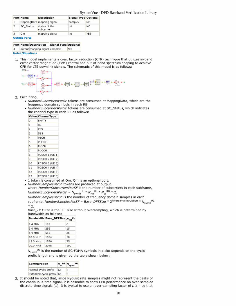
Port Name Description Signal Type Optional
1 MappingData mapping signal complex NO
2 SC_Status status of thesubcarrier
int NO
3 Qm mapping signal int YES
Output Ports
Port Name Description Signal Type Optional
4 output mapping signal complex NO
Notes/Equations
This model implements a crest factor reduction (CFR) technique that utilizes in-band1.error vector magnitude (EVM) control and out-of-band spectrum shaping to achieveCFR for LTE downlink signals. The schematic of this model is as follows:
Each firing,2.NumberSubcarriersPerSF tokens are consumed at MappingData, which are thefrequency domain symbols in each RE:NumberSubcarriersPerSF tokens are consumed at SC_Status, which indicatesthe channel type in each RE as follows:Value ChannelType
0 EMPTY
1 RS
2 PSS
3 SSS
4 PBCH
5 PCFICH
6 PHICH
7 PDCCH
8 PDSCH 1 (UE 1)
9 PDSCH 2 (UE 2)
10 PDSCH 3 (UE 3)
11 PDSCH 4 (UE 4)
12 PDSCH 5 (UE 5)
13 PDSCH 6 (UE 6)
1 token is consumed at Qm. Qm is an optional port;NumberSamplesPerSF tokens are produced at output.where NumberSubcarriersPerSF is the number of subcarriers in each subframe,NumberSubcarriersPerSF = Nsymb
UL * NRBUL * Nsc
RB * 2.
NumberSamplesPerSF is the number of frequency domain samples in eachsubframe, NumberSamplesPerSF = Base_DFTSize * 2OversamplingOption * Nsymb
UL
* 2.Base_DFTSize is the FFT size without oversampling, which is determined byBandwidth as follows:Bandwidth Base_DFTSize NRB
UL
1.4 MHz 128 6
3.0 MHz 256 15
5.0 MHz 512 25
10.0 MHz 1024 50
15.0 MHz 1536 75
20.0 MHz 2048 100
NsymbUL is the number of SC-FDMA symbols in a slot depends on the cyclic
prefix length and is given by the table shown below:
Configuration NscRB Nsymb
UL
Normal cyclic prefix 12 7
Extended cyclic prefix 12 6
It should be noted that, since Nyquist rate samples might not represent the peaks of3.the continuous-time signal, it is desirable to show CFR performance on over-sampleddiscrete-time signals [1]. It is typical to use an over-sampling factor of L ≥ 4 so that

SystemVue - DPD Baseband Verification Library
11
the PAR before the digital to analog (D/A) conversion can accurately describe the PARafter the D/A conversion.The overall structure of the CFR scheme is shown in the following figure. First, the4.LTE downlink signal is simply clipped at some optimized clipping level. Next, thesignal is transformed to the frequency domain. Afterwards, in-band and out-of-bandprocessing are performed to ensure that the EVM and spectral mask requirementsare met. Finally, the outgoing low-PAR symbol is created with an inverse DFToperation.
See also DPD_LTE_CFR_PostProc (dpdbasever) and DPD_LTE_DL_Src_CFR5.(dpdbasever).
References
Robert J. Baxley, Chunming Zhao and G. Tong Zhou, “Constrained Clipping for Crest1.Factor Reduction in OFDM”, IEEE Trans. on Broadcasting, VOL. 52, NO. 4, December2006.

SystemVue - DPD Baseband Verification Library
12
DPD_LTE_DL_Src_CFR Part LTE downlink baseband source with crest factor reduction
Categories: DPD Category (dpdbasever)
The models associated with this part are listed below. To view detailed information on amodel (description, parameters, equations, notes, etc.), please click the appropriate link.
Model
DPD_LTE_DL_Src_CFR (dpdbasever)
DPD_LTE_DL_Src_CFR
Description: LTE downlink baseband source with crest factor reductionAssociated Parts: DPD LTE DL Src CFR Part (dpdbasever)
Model Parameters
Name Description Default Units Type RuntimeTunable
ShowSystemParameters show system parameters for LTEdownlink signals: NO, YES
YES Enumeration NO
FrameMode frame mode: FDD, TDD FDD Enumeration NO
TDD_Config downlink and uplink allocations for TDD:Config 0, Config 1, Config 2, Config 3,Config 4, Config 5, Config 6
Config 0 Enumeration NO
SpecialSF_Config downlink and uplink allocations for TDD:Config 0, Config 1, Config 2, Config 3,Config 4, Config 5, Config 6, Config 7,Config 8
Config 4 Enumeration NO
Bandwidth bandwidth: BW 1.4 MHz, BW 3 MHz, BW5 MHz, BW 10 MHz, BW 15 MHz, BW 20MHz
BW 10 MHz Enumeration NO
OversamplingOption oversampling option: Ratio 1, Ratio 2,Ratio 4, Ratio 8
Ratio 4 Enumeration NO
CyclicPrefix type of cyclic prefix: Normal, Extended Normal Enumeration NO
CellID_Sector the index of cell identity group 0 Integer NO
CellID_Group the index of cell identity within thephysical-layer cell-identity group
0 Integer NO
RB_MappingType the mapping type of VRBs to PRBs:Localized, Distributed
Localized Enumeration NO
ShowUE1_Parameters show parameters for coded UE1: NO,YES
YES Enumeration NO
UE1_HARQ_Enable Whether HARQ closed-loop transmissionis enable: NO, YES
YES Enumeration NO
UE1_NumHARQ Number of HARQ processes 8 Integer NO
UE1_MaxHARQTrans Maximum number of HARQ transmissionper each HARQ process
4 Integer NO
UE1_Config the configuration mode of input data forUE 1.: MCS index, Transport block size,Code rate
Transport block size Enumeration NO
UE1_Payload the input payload for UE 1, the meaningof the input is defined in UE1_Config
[2555,2555,2555,2555,2555,2555,2555,2555,2555,2555] Floatingpoint array
NO
UE1_MappingType the modulation orders for UE 1 in eachsubframe, valid when UE1_Payload isnot set to MCS index. (0:QPSK,1:16QAM, 2:64QAM)
[0,0,0,0,0,0,0,0,0,0] Integerarray
NO
UE1_RV_Sequence Redundancy Version Sequence for HARQclosed-loop transmission
[0, 1, 2, 3] Integerarray
NO
UE1_n_RNTI Radio network temporary identifier forUE 1
1 Integer NO
UE1_Category defines UE1 capability, used to get the Category 1 Enumeration NO
SystemVue - DPD Baseband Verification Library
13
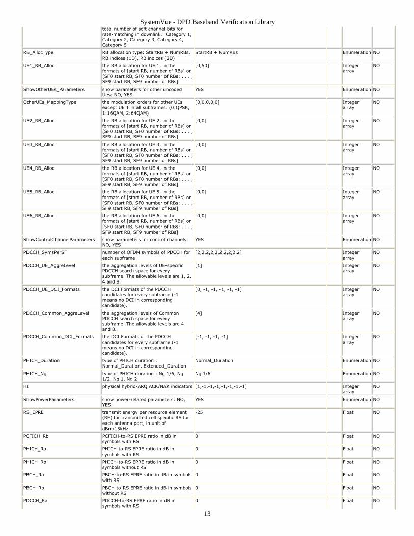
total number of soft channel bits forrate-matching in downlink.: Category 1,Category 2, Category 3, Category 4,Category 5
RB_AllocType RB allocation type: StartRB + NumRBs,RB indices (1D), RB indices (2D)
StartRB + NumRBs Enumeration NO
UE1_RB_Alloc the RB allocation for UE 1, in theformats of [start RB, number of RBs] or[SF0 start RB, SF0 number of RBs; . . . ;SF9 start RB, SF9 number of RBs]
[0,50] Integerarray
NO
ShowOtherUEs_Parameters show parameters for other uncodedUes: NO, YES
YES Enumeration NO
OtherUEs_MappingType the modulation orders for other UEsexcept UE 1 in all subframes. (0:QPSK,1:16QAM, 2:64QAM)
[0,0,0,0,0] Integerarray
NO
UE2_RB_Alloc the RB allocation for UE 2, in theformats of [start RB, number of RBs] or[SF0 start RB, SF0 number of RBs; . . . ;SF9 start RB, SF9 number of RBs]
[0,0] Integerarray
NO
UE3_RB_Alloc the RB allocation for UE 3, in theformats of [start RB, number of RBs] or[SF0 start RB, SF0 number of RBs; . . . ;SF9 start RB, SF9 number of RBs]
[0,0] Integerarray
NO
UE4_RB_Alloc the RB allocation for UE 4, in theformats of [start RB, number of RBs] or[SF0 start RB, SF0 number of RBs; . . . ;SF9 start RB, SF9 number of RBs]
[0,0] Integerarray
NO
UE5_RB_Alloc the RB allocation for UE 5, in theformats of [start RB, number of RBs] or[SF0 start RB, SF0 number of RBs; . . . ;SF9 start RB, SF9 number of RBs]
[0,0] Integerarray
NO
UE6_RB_Alloc the RB allocation for UE 6, in theformats of [start RB, number of RBs] or[SF0 start RB, SF0 number of RBs; . . . ;SF9 start RB, SF9 number of RBs]
[0,0] Integerarray
NO
ShowControlChannelParameters show parameters for control channels:NO, YES
YES Enumeration NO
PDCCH_SymsPerSF number of OFDM symbols of PDCCH foreach subframe
[2,2,2,2,2,2,2,2,2,2] Integerarray
NO
PDCCH_UE_AggreLevel the aggregation levels of UE-specificPDCCH search space for everysubframe. The allowable levels are 1, 2,4 and 8.
[1] Integerarray
NO
PDCCH_UE_DCI_Formats the DCI Formats of the PDCCHcandidates for every subframe (-1means no DCI in correspondingcandidate).
[0, -1, -1, -1, -1, -1] Integerarray
NO
PDCCH_Common_AggreLevel the aggregation levels of CommonPDCCH search space for everysubframe. The allowable levels are 4and 8.
[4] Integerarray
NO
PDCCH_Common_DCI_Formats the DCI Formats of the PDCCHcandidates for every subframe (-1means no DCI in correspondingcandidate).
[-1, -1, -1, -1] Integerarray
NO
PHICH_Duration type of PHICH duration :Normal_Duration, Extended_Duration
Normal_Duration Enumeration NO
PHICH_Ng type of PHICH duration : Ng 1/6, Ng1/2, Ng 1, Ng 2
Ng 1/6 Enumeration NO
HI physical hybrid-ARQ ACK/NAK indicators [1,-1,-1,-1,-1,-1,-1,-1] Integerarray
NO
ShowPowerParameters show power-related parameters: NO,YES
YES Enumeration NO
RS_EPRE transmit energy per resource element(RE) for transmitted cell specific RS foreach antenna port, in unit ofdBm/15kHz
-25 Float NO
PCFICH_Rb PCFICH-to-RS EPRE ratio in dB insymbols with RS
0 Float NO
PHICH_Ra PHICH-to-RS EPRE ratio in dB insymbols with RS
0 Float NO
PHICH_Rb PHICH-to-RS EPRE ratio in dB insymbols without RS
0 Float NO
PBCH_Ra PBCH-to-RS EPRE ratio in dB in symbolswith RS
0 Float NO
PBCH_Rb PBCH-to-RS EPRE ratio in dB in symbolswithout RS
0 Float NO
PDCCH_Ra PDCCH-to-RS EPRE ratio in dB insymbols with RS
0 Float NO

SystemVue - DPD Baseband Verification Library
14
PDCCH_Rb PDCCH-to-RS EPRE ratio in dB insymbols without RS
0 Float NO
PDSCH_PowerRatio PDSCH Cell Specific Ratio: p_B/p_A = 1,P_B = 0, P_B = 1, P_B = 2, P_B = 3
p_B/p_A = 1 Enumeration NO
UEs_Pa UE specific power parameter for each UE [0,0,0,0,0,0] Floatingpoint array
NO
PSS_Ra PSS-to-RS EPRE ratio in dB in symbolswithout RS
0 Float NO
SSS_Ra SSS-to-RS EPRE ratio in dB in symbolswithout RS
0 Float NO
ShowSpectrumShapingParameters show parameters for transmit spectrumshaping: NO, YES
NO Enumeration NO
SpectrumShapingType spectrum shaping method:TimeWindowing, FIRFilter
TimeWindowing Enumeration NO
WindowType type of time transition windowingbetween two consecutive symbols, validwhenSpectrumShapingType=TimeWindowing:Tukey, Raised cosine
Tukey Enumeration NO
CyclicInterval the overlapped cyclic interval betweentwo adjacent symbols in unit of chips(without oversampling), valid whenSpectrumShapingType=TimeWindowing
6 Integer NO
CI_StartPos the start position of cyclic interval(without oversampling), compared tothe start position of CP (negative meansahead of CP)
-3 Integer NO
FIR_Taps number of FIR filter taps, valid whenSpectrumShapingType=FIRFilter
19 Integer NO
FIR_withInterp whether spectrum-shaping FIR filterwith interpolation operation or not, validwhen SpectrumShapingType=FIRFilter:NO, YES
NO Enumeration NO
FIR_FilterType spectrum-shaping FIR filter type, validwhen SpectrumShapingType=FIRFilter:RRC, Ideal Lowpass, EquiRipple
RRC Enumeration NO
RRC_Alpha roll-off factor for root raised-cosinefilter, valid whenSpectrumShapingType=FIRFilter
0.22 Float NO
DisplayMsg the messages displayed in SimulationLog window: None, Simple, Full
Simple Enumeration NO
CFREnable whether enable CFR or not: NO, YES YES Enumeration NO
ClippingThreshold clipping threshold used in CFR 0 Float NO
EVM_Threshold_QPSK EVM threshold for QPSK used in CFR 0.1 Float NO
EVM_Threshold_16QAM EVM threshold for 16QAM used in CFR 0.1 Float NO
EVM_Threshold_64QAM EVM threshold for 64QAM used in CFR 0.1 Float NO
Input Ports
Port Name Description Signal Type Optional
1 UE1_Data Input of UE1 information bits int NO
7 HARQ_Bits UE1 HARQ ACK/NACK bits feedbacked from the receiver int YES
Output Ports
Port Name Description Signal Type Optional
2 frm_TD Output of baseband time-domain data complex NO
3 frm_FD Output of frequency data without power setting complex NO
4 UE1_ModSymbols UE1 Matrix-based (subframe-based) modulation symbols complex matrix NO
5 UE1_ChannelBits UE1 Matrix-based (subframe-based) channel bits int matrix NO
6 SC_Status Output of resource element status int NO
Notes/Equations
This model generates 3GPP LTE coded downlink baseband signal (up to six users1.(PDSCHs)) with one transmit antenna port. CFR (Crest Factor Reduction) can beenabled by setting parameter CFREnable to YES. The schematic is shown below:

SystemVue - DPD Baseband Verification Library
15
CFR parameters details:2.CFREnable: whether enable CFR or not, if CFREnable is set to NO, this model isthe same as LTE_DL_Src (ltebasever).ClippingThreshold: the threshold for the simple clipping, the maximummagnitude of the clipped signal would be no larger than ClippingThresholdEVM_Threshold_QPSK: the EVM threshold set for QPSK symbols.EVM_Threshold_16QAM: the EVM threshold set for 16QAM symbols.EVM_Threshold_64QAM: the EVM threshold set for 64QAM symbols.
There is a tradeoff between the EVM threshold and the PAPR of the signal after CFR.3.Generally speaking, if you set a tighter EVM threshold, the PAPR would be higher.The ClippingThreshold should always be carefully configured to get the lowest PAPRfor a given EVM threshold.For more information, please refer to LTE_DL_Src (ltebasever) and DPD_LTE_CFR4.(dpdbasever).
References

SystemVue - DPD Baseband Verification Library
16
DPD_PAModel Part PA model
Categories: DPD Category (dpdbasever)
The models associated with this part are listed below. To view detailed information on amodel (description, parameters, equations, notes, etc.), please click the appropriate link.
Model
DPD_PAModel (dpdbasever)
DPD_PAModel
Description: PA modelAssociated Parts: DPD PAModel Part (dpdbasever)
Input Ports
Port Name Description Signal Type Optional
1 PA_IN Terminal: Standard Data PortTerminal
complex NO
Output Ports
Port Name Description Signal Type Optional
2 PA_OUT Terminal: Standard Data PortTerminal
complex NO
Notes/Equations
This model implements the reference power amplifier model presented by Freescale1.[1]. The schematic of this model is as follows:
This model is modifiable as users can change the parameters in the subcircuit.2.As can be found in [1], the curves below show am-to-am characteristics, gain in3.function of input level and am-to-pm transfer function. Note the high compressionand Psat in the am-to-am and gain curves. The gain curve cannot show Psat as Gain is
undefined at the saturation point and beyond. The am-to-am and am-to-pm patterns(first and third plots below) are continuous and have continuous derivatives.

SystemVue - DPD Baseband Verification Library
17
References
TSG RAN WG4 meeting # 48bis,R4-082544, " Improved Reference Power Amplifier1.Model for UE Transmitter Simulations (Revised)", Sep. 29 – Oct. 3, 2008.

SystemVue - DPD Baseband Verification Library
18
DPD_RadiusClip Part Clipping for complex inputs
Categories: DPD Category (dpdbasever)
The models associated with this part are listed below. To view detailed information on amodel (description, parameters, equations, notes, etc.), please click the appropriate link.
Model
DPD_RadiusClip (dpdbasever)
DPD_RadiusClip
Description: Clipping for complex inputsAssociated Parts: DPD RadiusClip Part (dpdbasever)
Model Parameters
Name Description Default Units Type Runtime Tunable
ClippingThreshold ClippingThreshold
1 Float NO
Input Ports
Port Name Description Signal Type Optional
1 input Terminal: Standard Data PortTerminal
complex NO
Output Ports
Port Name Description Signal Type Optional
2 output Terminal: Standard Data PortTerminal
complex NO
Notes/Equations
This model is used to simply clip the input signal to some level ClippingThreshold.1.The schematic of this model is as follows:
Each firing, 1 token is consumed at port input, 1 token is produced at port output.2.Clipping input x with threshold Amax yields3.
See also DPD_WCDMA_Clip (dpdbasever) and DPD_LTE_CFR (dpdbasever).4.
References

SystemVue - DPD Baseband Verification Library
19
DPD_WCDMA_Clip Part WCDMA clipping for up to 4 carriers timed inputs
Categories: DPD Category (dpdbasever)
The models associated with this part are listed below. To view detailed information on amodel (description, parameters, equations, notes, etc.), please click the appropriate link.
Model
DPD_WCDMA_Clip (dpdbasever)
DPD_WCDMA_Clip
Description: WCDMA clipping for up to 4 carriers timed inputsAssociated Parts: DPD WCDMA Clip Part (dpdbasever)
Model Parameters
Name Description Default Units Type RuntimeTunable
RF_Freq RF frequency 2140000000 Hz Float NO
NumCarriers number of carriers: One carrier, Twocarriers, Three carriers, Four carriers
Two carriers Enumeration NO
ClippingThreshold clipping threshold 1 Float NO
Input Ports
Port Name Description Signal Type Optional
0 in Terminal: Standard Data PortTerminal
envelope NO
Output Ports
Port Name Description Signal Type Optional
0 out Terminal: Standard Data PortTerminal
envelope NO
Notes/Equations
This model is used to clip the WCDMA signal which may consists of 1 carrier, 21.carriers, 3 carriers or 4 carriers. The schematic of this model is as follows:
The signal is firstly simply clipped to some level ClippingThreshold. The clipping is2.followed by band pass filtering to reduce the out-of-band power. The default bandpass filters used are Parks-McClellan filters with maximum filter order equal to 512.Users can open the subcircuit and change the parameter for the filters.Parameter Details:3.
RF_Freq: RF frequency of the WCDMA signalNumCarriers: number of carriers, it can be selected as One carrier, Two carriers,Three carriers and Four carriers. It determines which filters would be used in theschematic.ClippingThreshold: the threshold for clipping.
See also DPD_RadiusClip (dpdbasever) and DPD_LTE_CFR (dpdbasever).4.
References
SystemVue - DPD Baseband Verification Library
20
DPD_WCDMA_RF_Mod Part WCDMA RF Modulator
Categories: DPD Category (dpdbasever)
The models associated with this part are listed below. To view detailed information on amodel (description, parameters, equations, notes, etc.), please click the appropriate link.
Model
DPD_WCDMA_RF_Mod (dpdbasever)
DPD_WCDMA_RF_Mod
Description: WCDMA RF ModulatorAssociated Parts: DPD WCDMA RF Mod Part (dpdbasever)
Model Parameters
Name Description Default Units Type RuntimeTunable
SampPerSym number of samples per symbol 8 Integer NO
FilterLength length of raised cosine filters innumber of symbols
16 Integer NO
ExcessBW Excess bandwidth 0.22 Float NO
FCarrier Carrier frequency (used if optionalLO input not used)
2000000000 Hz Float NO
Power RF tone carrier power 0.01 W Float NO
AmpSensitivity Amplitude sensitivity 1 Float NO
I_OriginOffset I origin offset 0 Float NO
Q_OriginOffset Q origin offset 0 Float NO
IQ_Rotation IQ rotation 0 deg Float NO
GainImbalance Gain imbalance in dB, Q channelrelative to I channel
0 Float NO
PhaseImbalance Phase imbalance, Q channel relativeto I channel
0 deg Float NO
NDensity Noise power spectral density 0 W Float NO
ConjugatedQuadrature Negate quadrature output: NO, YES NO Enumeration NO
Input Ports
Port Name Description Signal Type Optional
1 I_In Terminal: Standard Data PortTerminal
real NO
2 Q_In Terminal: Standard Data PortTerminal
real NO
Output Ports
Port Name Description Signal Type Optional
3 RF_Out Terminal: Standard Data PortTerminal
envelope NO
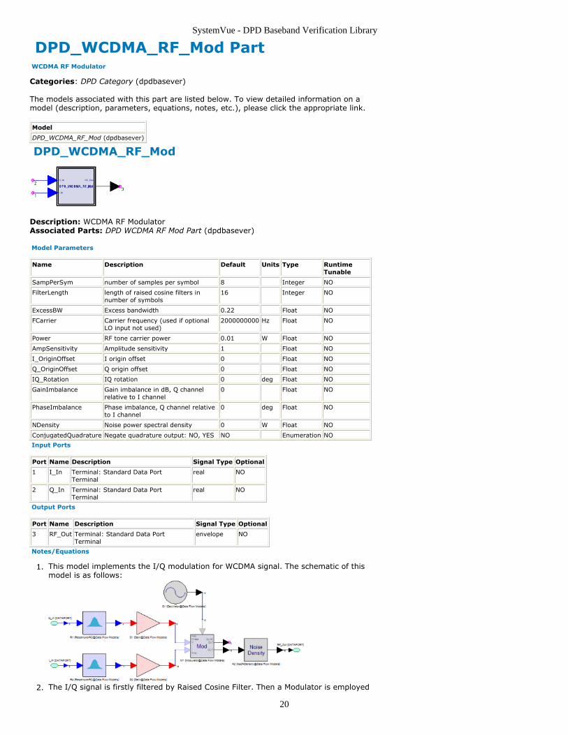
Notes/Equations
This model implements the I/Q modulation for WCDMA signal. The schematic of this1.model is as follows:
The I/Q signal is firstly filtered by Raised Cosine Filter. Then a Modulator is employed2.

SystemVue - DPD Baseband Verification Library
21
followed by a AddNDensity model to add noise. See ResamplerRC (algorithm),Modulator (algorithm) and AddNDensity (algorithm).
References
SystemVue - DPD Baseband Verification Library
22
DPD_AM_AM PartCategories: DPD (dpdbasever)
The models associated with this part are listed below. To view detailed information on amodel (description, parameters, equations, notes, etc.), please click the appropriate link.
Model Description
DPD_AM_AM (dpdbasever) calcualte the AM-AM characteristic from the input and output of thedevice
DPD_AM_AM
Description: calcualte the AM-AM characteristic from the input and output of the deviceDomain: UntimedC++ Code Generation Support: NOAssociated Parts: DPD AM AM Part (dpdbasever)
Input Ports
Port Name Description Signal Type Optional
1 OutputSig Output signal of the device complex NO
2 InputSig Input signal of the device complex NO
Output Ports
Port Name Description Signal Type Optional
3 Pout power of the output signal real NO
4 PinOverPout ratio of the power of the input signal over output signal real NO
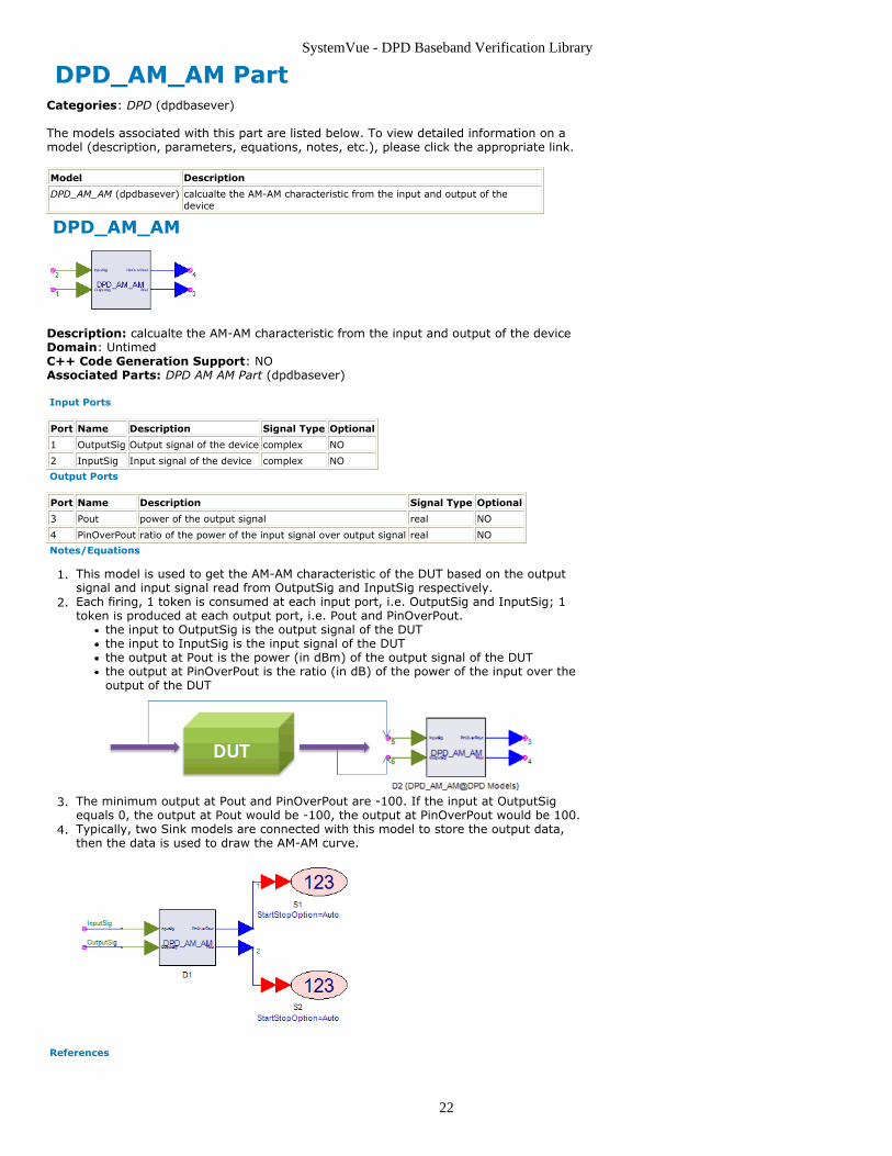
Notes/Equations
This model is used to get the AM-AM characteristic of the DUT based on the output1.signal and input signal read from OutputSig and InputSig respectively.Each firing, 1 token is consumed at each input port, i.e. OutputSig and InputSig; 12.token is produced at each output port, i.e. Pout and PinOverPout.
the input to OutputSig is the output signal of the DUTthe input to InputSig is the input signal of the DUTthe output at Pout is the power (in dBm) of the output signal of the DUTthe output at PinOverPout is the ratio (in dB) of the power of the input over theoutput of the DUT
The minimum output at Pout and PinOverPout are -100. If the input at OutputSig3.equals 0, the output at Pout would be -100, the output at PinOverPout would be 100.Typically, two Sink models are connected with this model to store the output data,4.then the data is used to draw the AM-AM curve.
References
SystemVue - DPD Baseband Verification Library
23
DPD_LTE_CFR_PostProc PartCategories: DPD (dpdbasever)
The models associated with this part are listed below. To view detailed information on amodel (description, parameters, equations, notes, etc.), please click the appropriate link.
Model Description
DPD_LTE_CFR_PostProc (dpdbasever) crest factor reduction post processing
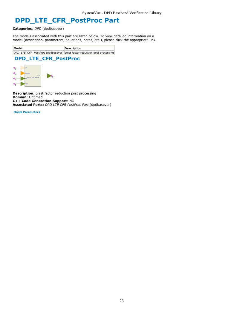
DPD_LTE_CFR_PostProc
Description: crest factor reduction post processingDomain: UntimedC++ Code Generation Support: NOAssociated Parts: DPD LTE CFR PostProc Part (dpdbasever)
Model Parameters
SystemVue - DPD Baseband Verification Library
24
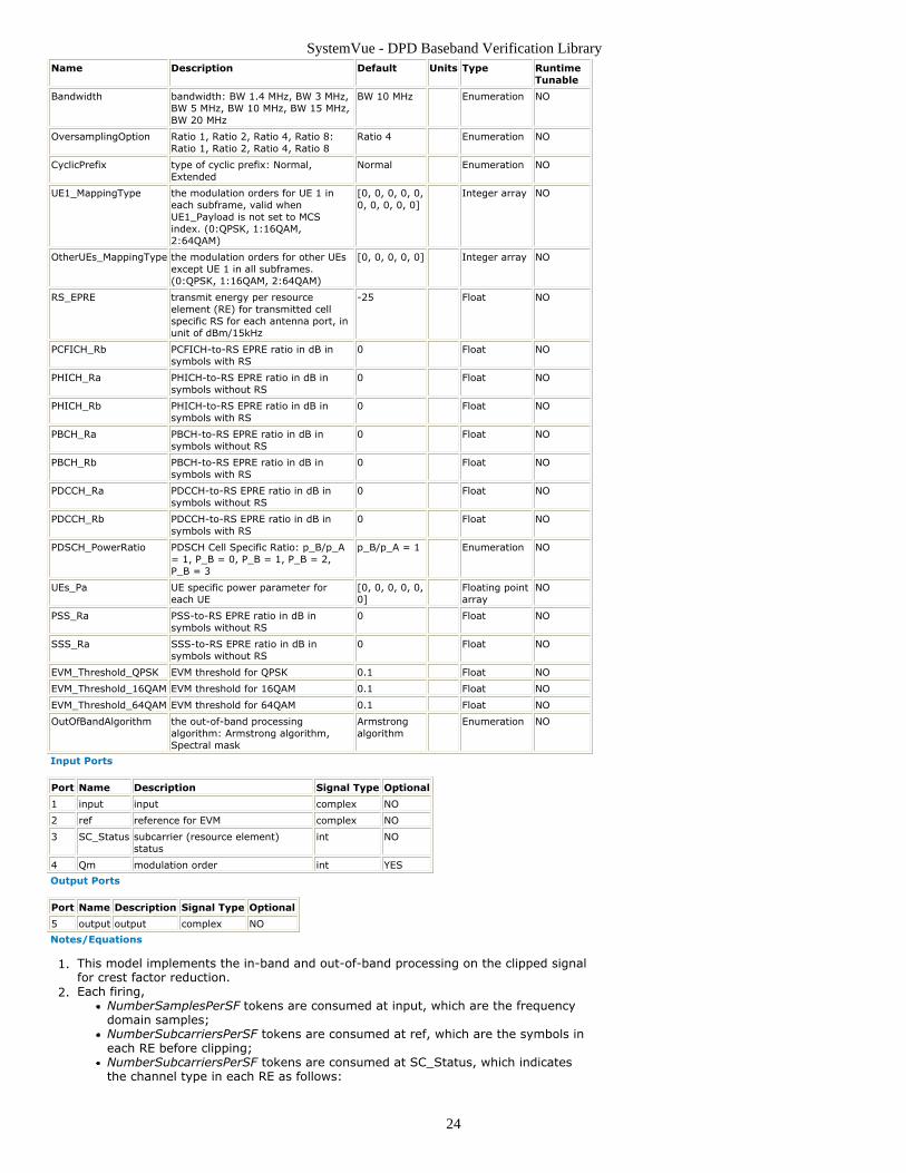
Name Description Default Units Type RuntimeTunable
Bandwidth bandwidth: BW 1.4 MHz, BW 3 MHz,BW 5 MHz, BW 10 MHz, BW 15 MHz,BW 20 MHz
BW 10 MHz Enumeration NO
OversamplingOption Ratio 1, Ratio 2, Ratio 4, Ratio 8:Ratio 1, Ratio 2, Ratio 4, Ratio 8
Ratio 4 Enumeration NO
CyclicPrefix type of cyclic prefix: Normal,Extended
Normal Enumeration NO
UE1_MappingType the modulation orders for UE 1 ineach subframe, valid whenUE1_Payload is not set to MCSindex. (0:QPSK, 1:16QAM,2:64QAM)
[0, 0, 0, 0, 0,0, 0, 0, 0, 0]
Integer array NO
OtherUEs_MappingType the modulation orders for other UEsexcept UE 1 in all subframes.(0:QPSK, 1:16QAM, 2:64QAM)
[0, 0, 0, 0, 0] Integer array NO
RS_EPRE transmit energy per resourceelement (RE) for transmitted cellspecific RS for each antenna port, inunit of dBm/15kHz
-25 Float NO
PCFICH_Rb PCFICH-to-RS EPRE ratio in dB insymbols with RS
0 Float NO
PHICH_Ra PHICH-to-RS EPRE ratio in dB insymbols without RS
0 Float NO
PHICH_Rb PHICH-to-RS EPRE ratio in dB insymbols with RS
0 Float NO
PBCH_Ra PBCH-to-RS EPRE ratio in dB insymbols without RS
0 Float NO
PBCH_Rb PBCH-to-RS EPRE ratio in dB insymbols with RS
0 Float NO
PDCCH_Ra PDCCH-to-RS EPRE ratio in dB insymbols without RS
0 Float NO
PDCCH_Rb PDCCH-to-RS EPRE ratio in dB insymbols with RS
0 Float NO
PDSCH_PowerRatio PDSCH Cell Specific Ratio: p_B/p_A= 1, P_B = 0, P_B = 1, P_B = 2,P_B = 3
p_B/p_A = 1 Enumeration NO
UEs_Pa UE specific power parameter foreach UE
[0, 0, 0, 0, 0,0]
Floating pointarray
NO
PSS_Ra PSS-to-RS EPRE ratio in dB insymbols without RS
0 Float NO
SSS_Ra SSS-to-RS EPRE ratio in dB insymbols without RS
0 Float NO
EVM_Threshold_QPSK EVM threshold for QPSK 0.1 Float NO
EVM_Threshold_16QAM EVM threshold for 16QAM 0.1 Float NO
EVM_Threshold_64QAM EVM threshold for 64QAM 0.1 Float NO
OutOfBandAlgorithm the out-of-band processingalgorithm: Armstrong algorithm,Spectral mask
Armstrongalgorithm
Enumeration NO
Input Ports
Port Name Description Signal Type Optional
1 input input complex NO
2 ref reference for EVM complex NO
3 SC_Status subcarrier (resource element)status
int NO
4 Qm modulation order int YES
Output Ports
Port Name Description Signal Type Optional
5 output output complex NO
Notes/Equations
This model implements the in-band and out-of-band processing on the clipped signal1.for crest factor reduction.Each firing,2.
NumberSamplesPerSF tokens are consumed at input, which are the frequencydomain samples;NumberSubcarriersPerSF tokens are consumed at ref, which are the symbols ineach RE before clipping;NumberSubcarriersPerSF tokens are consumed at SC_Status, which indicatesthe channel type in each RE as follows:

SystemVue - DPD Baseband Verification Library
25
Value ChannelType
0 EMPTY
1 RS
2 PSS
3 SSS
4 PBCH
5 PCFICH
6 PHICH
7 PDCCH
8 PDSCH 1 (UE 1)
9 PDSCH 2 (UE 2)
10 PDSCH 3 (UE 3)
11 PDSCH 4 (UE 4)
12 PDSCH 5 (UE 5)
13 PDSCH 6 (UE 6)
1 token is consumed at Qm. Qm is an optional port;NumberSamplesPerSF tokens are produced at output.where NumberSamplesPerSF is the number of frequency domain samples ineach subframe, NumberSamplesPerSF = Base_DFTSize * 2OversamplingOption * N
symbUL * 2.
Base_DFTSize is the FFT size without oversampling, which is determined byBandwidth as follows:Bandwidth Base_DFTSize NRB
UL
1.4 MHz 128 6
3.0 MHz 256 15
5.0 MHz 512 25
10.0 MHz 1024 50
15.0 MHz 1536 75
20.0 MHz 2048 100
NsymbUL is the number of SC-FDMA symbols in a slot depends on the cyclic
prefix length and is given by the table shown below:
Configuration NscRB Nsymb
UL
Normal cyclic prefix 12 7
Extended cyclic prefix 12 6
NumberSubcarriersPerSF is the number of subcarriers in each subframe,NumberSubcarriersPerSF = Nsymb
UL * NRBUL * Nsc
RB * 2.
The in-band processing algorithm strives to obtain a signal whose EVM is below the3.threshold (varies from mapping type) and whose PAPR (Peak to Average PowerRatio) is at a low level [1]. Moreover, it struggles to minimize the distortion on thephysical signals, i.e. PSS, SSS and RS, which are important for the synchronizationand channel estimation in the receiver side.
The EVM for different modulation schemes on PDSCH shall be better than thelimits in the following [3]:Modulation scheme for PDSCH Required EVM [%]
QPSK 17.5 %
16QAM 12.5 %
64QAM 8 %
The OutOfBandAlgorithm can be selected as Armstrong Algorithm and Spectral Mask.4.For Armstrong Algorithm [2], the out-of-band components are nulled. For SpectralMask [1], a spectral clipping operation is performed to guarantee that the out-of-band parts of the signal that exceed the spectral mask back down to the spectralmask [3].See also DPD_LTE_CFR (dpdbasever) and DPD_LTE_DL_Src_CFR (dpdbasever).5.
References
Robert J. Baxley, Chunming Zhao and G. Tong Zhou, “Constrained Clipping for Crest1.Factor Reduction in OFDM”, IEEE Trans. on Broadcasting, VOL. 52, NO. 4, December2006.J. Armstrong, “New OFDM peak-to-average power reduction scheme”, in Proc. IEEE2.VTS 53rd Vehicular Technology Conference, May 2001, vol. 1, pp. 756-760.3GPP TS 36.104 v8.8.0, "Base Station (BS) radio transmission and reception",3.December 2009.
SystemVue - DPD Baseband Verification Library
26
DPD_ModelExtractor PartCategories: DPD (dpdbasever)
The models associated with this part are listed below. To view detailed information on amodel (description, parameters, equations, notes, etc.), please click the appropriate link.
Model Description
DPD_ModelExtractor (dpdbasever) DPD model extraction
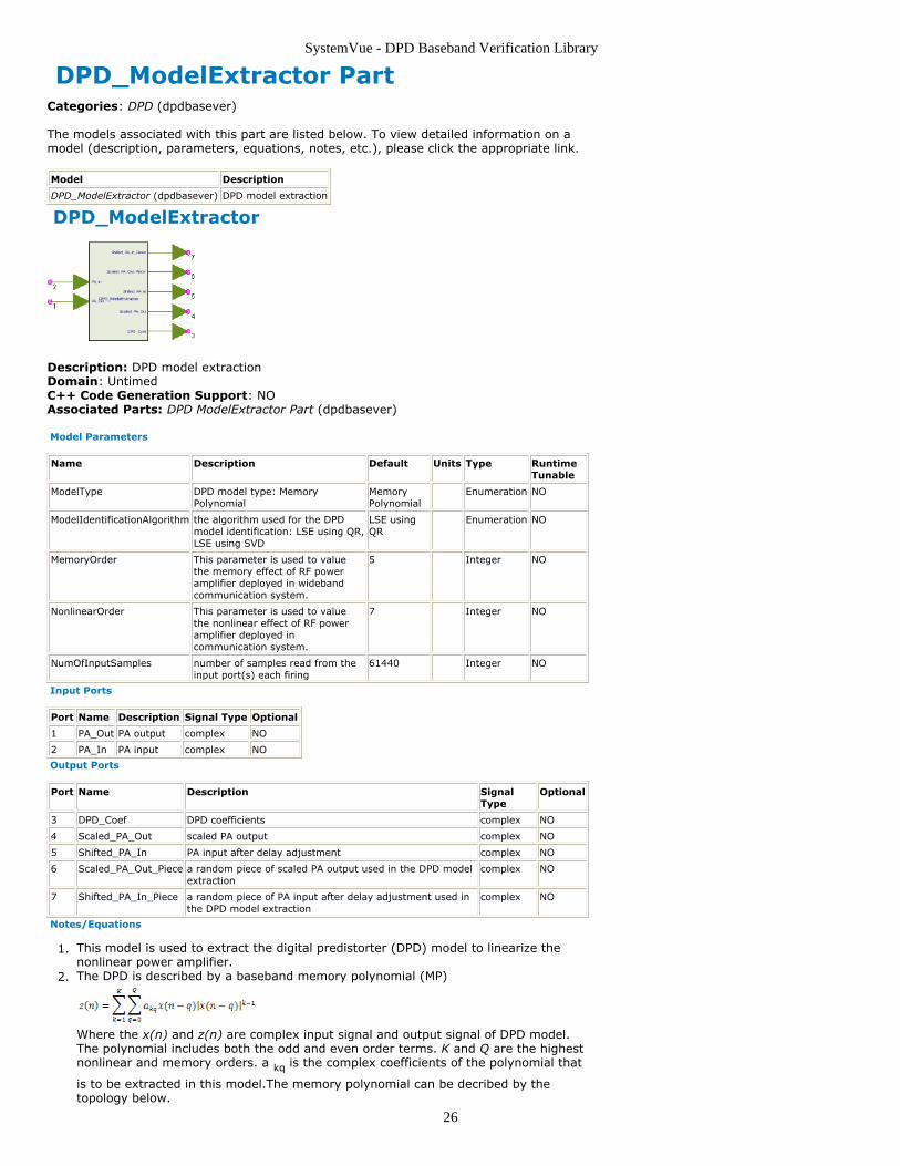
DPD_ModelExtractor
Description: DPD model extractionDomain: UntimedC++ Code Generation Support: NOAssociated Parts: DPD ModelExtractor Part (dpdbasever)
Model Parameters
Name Description Default Units Type RuntimeTunable
ModelType DPD model type: MemoryPolynomial
MemoryPolynomial
Enumeration NO
ModelIdentificationAlgorithm the algorithm used for the DPDmodel identification: LSE using QR,LSE using SVD
LSE usingQR
Enumeration NO
MemoryOrder This parameter is used to valuethe memory effect of RF poweramplifier deployed in widebandcommunication system.
5 Integer NO
NonlinearOrder This parameter is used to valuethe nonlinear effect of RF poweramplifier deployed incommunication system.
7 Integer NO
NumOfInputSamples number of samples read from theinput port(s) each firing
61440 Integer NO
Input Ports
Port Name Description Signal Type Optional
1 PA_Out PA output complex NO
2 PA_In PA input complex NO
Output Ports
Port Name Description SignalType
Optional
3 DPD_Coef DPD coefficients complex NO
4 Scaled_PA_Out scaled PA output complex NO
5 Shifted_PA_In PA input after delay adjustment complex NO
6 Scaled_PA_Out_Piece a random piece of scaled PA output used in the DPD modelextraction
complex NO
7 Shifted_PA_In_Piece a random piece of PA input after delay adjustment used inthe DPD model extraction
complex NO
Notes/Equations
This model is used to extract the digital predistorter (DPD) model to linearize the1.nonlinear power amplifier.The DPD is described by a baseband memory polynomial (MP)2.
Where the x(n) and z(n) are complex input signal and output signal of DPD model.The polynomial includes both the odd and even order terms. K and Q are the highestnonlinear and memory orders. a kq is the complex coefficients of the polynomial that
is to be extracted in this model.The memory polynomial can be decribed by thetopology below.

SystemVue - DPD Baseband Verification Library
27
The coefficients of the polynomial are extracted by indirect learning structure3.indicated in the following figure.[1][2]
The algorithm uses two identical MP models for the predistorter and training. The real4.predistorter block is the exact copy of the training block. It has x(n) as input and z(n)as output.The predistortion training block has y(n)/G as its input, and z(n) as itsoutput. y(n) is the PA output , and G is the expected gain of linearized PA. Usually, Gis the small signal gain or the maximum gain. If the nonlinearity of PA is completelycompensated by the predistorter, then y(n)=Gx(n). Therefore, z(n)=z'(n) and theerror term e(n)=0.Assume5.
If e(n) converges to zero, then6.
where z= [z(0),...z(N-1)] T, U=[u 10,..., u K0,...u 1Q,...,u KQ], u kq=[u kq (0),...,u kq
(N-1)] T, and a=[a 10,...a K0,..., a 1Q,...,a KQ] T
Two model identification methods are provided: LSE using QR and LSE using SVD7.In the model identification, the PA output is normalized by the small-signal gain and8.then used as the input of the DPD model.The PA input is taken as the output of theDPD model.Only part of the signal is used to do model identification.9.Accurate synchronization of the PA input and output signal is implemented in this10.algorithm[3]. The PA input and output after normalization and delay adjustment aregiven as output of this model.Normalized mean squared error (NMSE) is used to evaluate how close the PA input11.and the DPD model output, see DPD_NMSE (dpdbasever)Highest nonlinear order K and memory order Q are key parameters that decide how12.well the DPD model works. Users are suggested to start from smaller K and Q. If theNMSE cannot meet requirement, increase K and Q step by step. The highest K and Qof this model are 18 and 9 respectively.
References
1. C. Eun and E. J. Powers, "A New Volterra Predistorter Based on the Indirect LearningArchitecture," IEEE Trans. Signal Processing, Vol. 45, pp.223-227, Jan., 19972. L. Ding, G.T.Zhou, Z. Ma, D.R. Morgan, J.S. Kenney,J. Kim, and C.R. Giardina, “A

SystemVue - DPD Baseband Verification Library
28
robust digital baseband predistorter constructed using memory polynomials,”IEEE Trans.on Communications, Vol.52, pp.159-165, March, 20023. S. Boumaiza, M. Helaoui, O. Hammi, T. Liu, and F. M. Ghannouchi, "Systematic andAdaptive Characterization Approach for Behavior Modeling of Dynamic NonlinearTransmitters", IEEE Trans. on Instrum. and Meas., Vol.56, pp.2203-2211,Dec., 2007

SystemVue - DPD Baseband Verification Library
29
DPD_NMSE PartCategories: DPD (dpdbasever)
The models associated with this part are listed below. To view detailed information on amodel (description, parameters, equations, notes, etc.), please click the appropriate link.
Model Description
DPD_NMSE (dpdbasever) calculate the normalized mean squared error between the two inputsignals
DPD_NMSE
Description: calculate the normalized mean squared error between the two input signalsDomain: UntimedC++ Code Generation Support: NOAssociated Parts: DPD NMSE Part (dpdbasever)
Model Parameters
Name Description Default Units Type RuntimeTunable
NumOfInputSamples number of samples read from the input port(s)each firing
61440 Integer NO
Input Ports
Port Name Description Signal Type Optional
1 InRef Input referencesignal
complex NO
2 InTest Input test signal complex NO
Output Ports
Port Name Description Signal Type Optional
3 NMSE NMSE real NO
Notes/Equations
This model calculates the normalized mean squared error (NMSE) between two input1.signalsThe NMSE value is expressed in dB2.
The DPD module pre-distorts the signal in a reverse manner. The input of the DPDmodel is the normalized output of the PA, and the desired output of the extractedDPD model is the input of the PA. For DPD model NMSE evaluation, x i is measured
PA input signal, y i is the extracted DPD model output signal. For PA model NMSE
evaluation, x i is measured PA output signal, y i is the extracted PA model output
signal.The smaller the NMSE, the more accurate the model. The recommended NMSE is less3.than -35dB.If the NMSE is too large, the extracted model cannot work effectively or even fails.4.Increasing the nonlinear order or memory order may improve NMSE.If the NMSE is still not low enough after nonlinear/memory order adjustment,5.lowering the operating point of PA is suggestedSee DPD_ModelExtractor (dpdbasever)6.
References
SystemVue - DPD Baseband Verification Library
30
DPD_PACoeffExtractor PartCategories: DPD (dpdbasever)
The models associated with this part are listed below. To view detailed information on amodel (description, parameters, equations, notes, etc.), please click the appropriate link.
Model Description
DPD_PACoeffExtractor (dpdbasever) PA model extraction
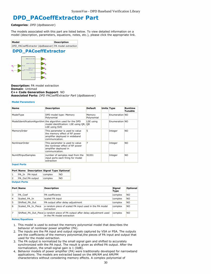
DPD_PACoeffExtractor
Description: PA model extractionDomain: UntimedC++ Code Generation Support: NOAssociated Parts: DPD PACoeffExtractor Part (dpdbasever)
Model Parameters
Name Description Default Units Type RuntimeTunable
ModelType DPD model type: MemoryPolynomial
MemoryPolynomial
Enumeration NO
ModelIdentificationAlgorithm the algorithm used for the DPDmodel identification: LSE using QR,LSE using SVD
LSE usingQR
Enumeration NO
MemoryOrder This parameter is used to valuethe memory effect of RF poweramplifier deployed in widebandcommunication.
5 Integer NO
NonlinearOrder This parameter is used to valuethe nonlinear effect of RF poweramplifier deployed incommunication.
7 Integer NO
NumOfInputSamples number of samples read from theinput ports each firing for modelextraction
92201 Integer NO
Input Ports
Port Name Description Signal Type Optional
1 PA_In PA input complex NO
2 PA_Out PA output complex NO
Output Ports
Port Name Description SignalType
Optional
3 PA_Coef PA coefficients complex NO
4 Scaled_PA_In scaled PA input complex NO
5 Shifted_PA_Out PA output after delay adjustment complex NO
6 Scaled_PA_In_Piece a random piece of scaled PA input used in the PA modelextraction
complex NO
7 Shifted_PA_Out_Piece a random piece of PA output after delay adjustment usedin the PA model extraction
complex NO
Notes/Equations
This model is used to extract the memory polynomial model that describes the1.behavior of nonlinear power amplifier (PA).The inputs are the PA input and output signals captured by VSA or PSA. The outputs2.are the coefficients of the memory polynomial,the pieces of PA input and output thatused for the model extraction.The PA output is normalized by the small signal gain and shifted to accurately3.synchronized with the PA input. The result is given as shifted PA output. After thenormalization, the small-signal gain is 1 (0dB).Behavior models of power amplifier (PA) were traditionally developed for narrowband4.applications. The models are extracted based on the AM/AM and AM/PMcharacteristics without considering memory effects. A complex polynomial of

SystemVue - DPD Baseband Verification Library
31
instantaneous input power is used to approximate the PA gain. However, with theincrease of signal bandwidth, memory effects cannot be ignored anymore. TheAM/AM and AM/PM characteristics are not constant, but change as the function ofboth the present and the past input signals. Several models were proposed todescribe the PA memory effects. One of the widely accepted models is the basebandmemorial polynomial model, which is the special case of Volterra model [1].
where x(n) and y(n) are complex input and output signals of PA captured by VSA orPSA , k is nonlinear order, q is memory order, and b kq is the complex coefficients of
the polynomial. This module is to extract those coefficients from measured x(n) andy(n).The memory polynomial can be seen as a nonlinear filter as shown in thefollowing graph.
The average input power should be kept to the level that the peak output power of5.the PA does not exceed 3dB gain compression point. Otherwise, the extraction errorwill be large.The highest nonlinear order K and memory order Q that can handled in this model6.are 18 and 9 respectively.For more information about coefficient extraction algorithm, see DPD_ModelExtractor7.(dpdbasever)
References
J. Kim and K. Konstantinou, “Digital predistortion of wideband signals based on1.power amplifier model with memory,” Electron. Lett., vol. 37, pp. 1417-1418, Nov.2001.

SystemVue - DPD Baseband Verification Library
32
DPD_PowerAlignment PartCategories: DPD (dpdbasever)
The models associated with this part are listed below. To view detailed information on amodel (description, parameters, equations, notes, etc.), please click the appropriate link.
Model Description
DPD_PowerAlignment (dpdbasever) calculate the power alignment, the mean power and peakpower
DPD_PowerAlignment
Description: calculate the power alignment, the mean power and peak powerDomain: UntimedC++ Code Generation Support: NOAssociated Parts: DPD PowerAlignment Part (dpdbasever)
Model Parameters
Name Description Default Units Type RuntimeTunable
NumOfInputSamples number of samples read from the input port(s)each firing
61440 Integer NO
Input Ports
Port Name Description Signal Type Optional
1 InputSig input signal of the PA complex NO
2 OutputSig output signal of the PA complex NO
Output Ports
Port Name Description Signal Type Optional
3 Gain gain real NO
4 Input_PeakPower peak power of the input signal in dBm real NO
5 Input_MeanPower mean power of the input signal in dBm real NO
6 Output_PeakPower peak power of the output signal in dBm real NO
7 Output_MeanPower mean power of the output signal indBm
real NO
Notes/Equations
1. This model is used to adjust the value of the baseband signal and the input signal ofthe extracted DPD model to the same range.2. The DPD model is extracted from the PA input and output signal captured by the PSA orVSA. The PA output normliazed by small-signal gain is taken as the input of DPD model.When the extracted DPD model is implemented, the actual input signal is the basebandsignal. To make the DPD?model work correctly, the baseband signal should be adjusted tothe same range as the normalized output of the PA. The Gain is the adjustment factor.3. Typically, the gain adjustment is implemented between the signal source and digitalpredistorter model as shown below. The value of Gain is the adjustment factor calculatedin this model.
References

SystemVue - DPD Baseband Verification Library
33
DPD_PreDistorter PartCategories: DPD (dpdbasever)
The models associated with this part are listed below. To view detailed information on amodel (description, parameters, equations, notes, etc.), please click the appropriate link.
Model Description
DPD_PreDistorter (dpdbasever) Digital Pre-distortion
DPD_PreDistorter
Description: Digital Pre-distortionDomain: UntimedC++ Code Generation Support: NOAssociated Parts: DPD PreDistorter Part (dpdbasever)
Model Parameters
Name Description Default Units Type RuntimeTunable
MemoryOrder This parameter is used to value the memory effectof RF power amplifier deployed in widebandcommunication system.
5 Integer NO
NonlinearOrder This parameter is used to value the nonlineareffect of RF power amplifier deployed incommunication system.
7 Integer NO
NumOfInputSamples number of samples read from the input port(s)each firing
61440 Integer NO
Input Ports
Port Name Description Signal Type Optional
1 DPD_Input input complex NO
2 DPD_Coef DPDcoefficients
complex NO
Output Ports
Port Name Description Signal Type Optional
3 DPD_Output Pre-Distortionoutput
complex NO
Notes/Equations
This is the digital predistortion model. It distorts the input baseband signal by using1.the extracted memory polynomial. See DPD_ModelExtractor (dpdbasever)
The inputs are the complex baseband signal x(n) to be distorted and the complex2.coefficients a kq of the memory polynomial that extracted in DPD_ModelExtractor
(dpdbasever).The topology structure is as below.

SystemVue - DPD Baseband Verification Library
34
Generally, the level of the baseband signal generated by the signal source needs to3.be adjusted, see DPD_PowerAlignment (dpdbasever)The output z(n) is the pre-distorted complex baseband signal and is downloaded to4.the ESG.
References