Embed Size (px)
Citation preview
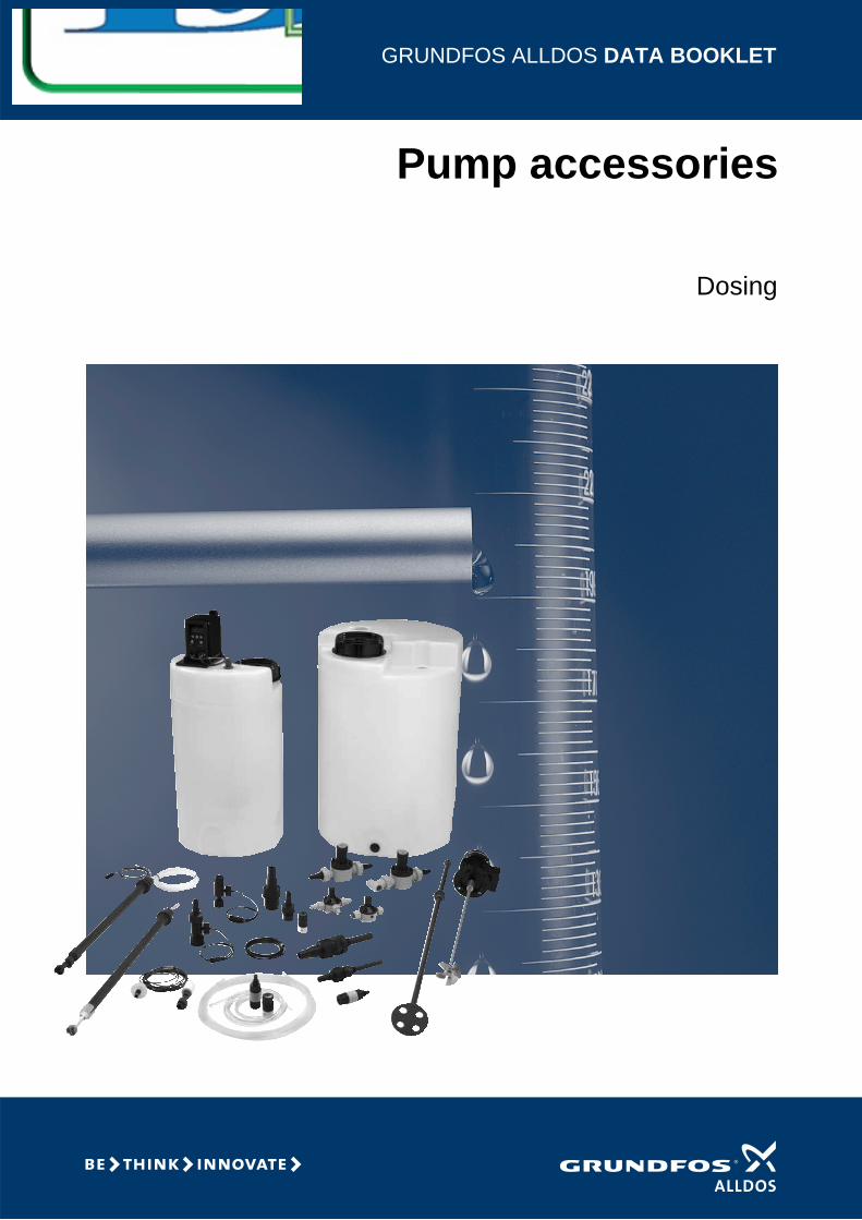
GRUNDFOS ALLDOS DATA BOOKLET
Pump accessories
Dosing
2
Contents
Overview of dosing systemOverview of dosing system 4
Installation kitsInstallation kits for DME and DMS dosing pumps 5Installation kits for DMI, DDI, DMX and DMH dosing pumps 6
TubingTubing 7
Pump connectionsPump connections, DME and DMS pumps 9Pump connections, DMI, DDI, DMX and DMH pumps 10Adapters for DME and DMS pumps 13Union nut kits 13
Foot valvesFoot valve 14
Suction linesFlexible suction lines 15Flexible suction lines DN 4 / DN 8 16Rigid suction lines 17Rigid suction lines for stationary tanks 17Rigid suction lines with drum adaptor 21Rigid suction lines for canisters 22Rigid suction lines for stationary tanks for largerpumps 23Rigid suction lines for drums or tanks for larger pumps 24Level-control unit 25
Injection valvesType key for injection valves 26Standard versions 27Injection valve with lip valve, DN 4 / DN 8, threaded connection G 5/8 33Hot-injection valve, M 30 34Hot-injection valve, DN 4 / DN 8 34Cooling pipe 34Injection valve with ball valve, DN 4 / DN 8, threaded connection G 5/8 35Injection valve, cleanable, DN 4 / DN 8, threaded connection G 5/8 35
Pressure-relief valvesDN 4 / DN 8 36DN 20 37DN 32 38DN 65 39
Pressure-loading valvesDN 4/DN 8 40DN 20 41DN 32 42DN 65 43
Multi-function valveMulti-function valve 44Multi-function valve selection 45Multi-function valve selection 46Accessories for multi-function valve 47
Pulsation dampersPulsation dampers 48Suction side pulsation dampers 49Selection of suction side pulsation dampers 50Accessories for suction side pulsation dampers 51Discharge side pulsation dampers without separating diaphragm 52Selection of discharge side pulsation dampers without separating diaphragm 53Options for discharge side pulsation dampers without separating diaphragm 55Discharge side pulsation dampers with separating diaphragm 56Selection of discharge side pulsation dampers with separating diaphragm, DN 8 56Selection of discharge side pulsation dampers with separating diaphragm, DN 20 57Selection of discharge side pulsation dampers with separating diaphragm, DN 32 and DN 65 58Accessories for discharge side pulsation dampers 59
TanksSquare tank, 100 litres 62Cylindrical tank 63Catchment tray / Bund 65Accessories for dosing tanks 66
Wall bracketWall bracket 67
Agitators and mixersElectric agitator 69Hand mixer 72
Automatic venting valveAutomatic venting valve 73
Diaphragm leakage sensorDiaphragm leakage sensor (DME 60-940 l/h) 74
Contents
Dosing monitorDosing monitor 75
Water meterWater meter 76
Cables and plugsDME and DMS 77DMI, DMX, DMH and DDI 78
Further product documentationWebCAPS 79WinCAPS 80
3
Pump accessories
4
Overview of dosing system
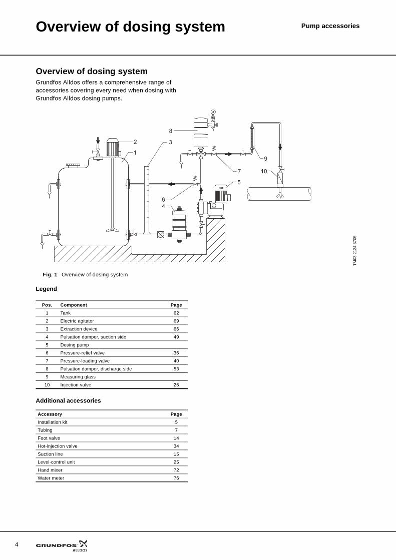
Overview of dosing systemGrundfos Alldos offers a comprehensive range of accessories covering every need when dosing with Grundfos Alldos dosing pumps.
Legend
Additional accessories
TM03
212
4 37
05
Fig. 1 Overview of dosing system
Pos. Component Page1 Tank 62
2 Electric agitator 69
3 Extraction device 66
4 Pulsation damper, suction side 49
5 Dosing pump
6 Pressure-relief valve 36
7 Pressure-loading valve 40
8 Pulsation damper, discharge side 53
9 Measuring glass
10 Injection valve 26
Accessory PageInstallation kit 5
Tubing 7
Foot valve 14
Hot-injection valve 34
Suction line 15
Level-control unit 25
Hand mixer 72
Water meter 76
Pump accessoriesInstallation kits
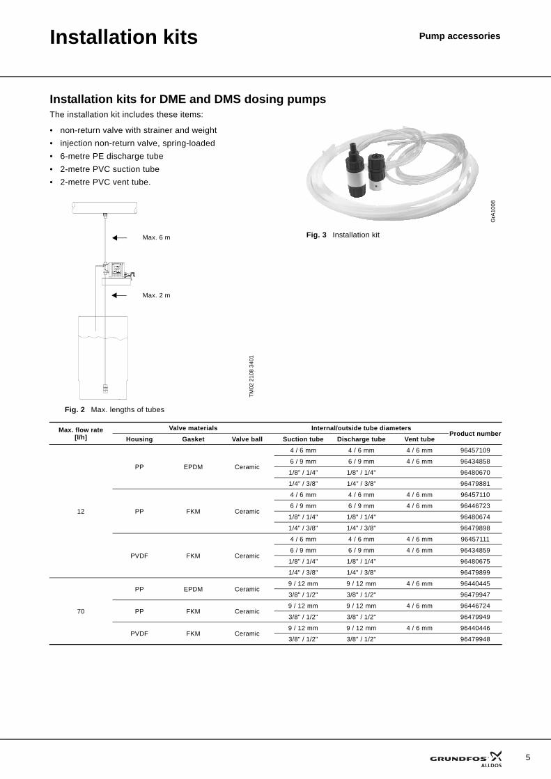
Installation kits for DME and DMS dosing pumpsThe installation kit includes these items:
• non-return valve with strainer and weight• injection non-return valve, spring-loaded• 6-metre PE discharge tube• 2-metre PVC suction tube• 2-metre PVC vent tube.
TM02
210
8 34
01
Fig. 2 Max. lengths of tubes
Max. 6 m
Max. 2 m
GrA
1008
Fig. 3 Installation kit
Max. flow rate[l/h]
Valve materials Internal/outside tube diametersProduct number
Housing Gasket Valve ball Suction tube Discharge tube Vent tube
12
PP EPDM Ceramic
4 / 6 mm 4 / 6 mm 4 / 6 mm 96457109
6 / 9 mm 6 / 9 mm 4 / 6 mm 96434858
1/8” / 1/4” 1/8" / 1/4" 96480670
1/4” / 3/8” 1/4” / 3/8” 96479881
PP FKM Ceramic
4 / 6 mm 4 / 6 mm 4 / 6 mm 96457110
6 / 9 mm 6 / 9 mm 4 / 6 mm 96446723
1/8" / 1/4" 1/8" / 1/4" 96480674
1/4" / 3/8" 1/4" / 3/8" 96479898
PVDF FKM Ceramic
4 / 6 mm 4 / 6 mm 4 / 6 mm 96457111
6 / 9 mm 6 / 9 mm 4 / 6 mm 96434859
1/8" / 1/4" 1/8" / 1/4" 96480675
1/4" / 3/8" 1/4" / 3/8" 96479899
70
PP EPDM Ceramic9 / 12 mm 9 / 12 mm 4 / 6 mm 96440445
3/8" / 1/2" 3/8" / 1/2" 96479947
PP FKM Ceramic9 / 12 mm 9 / 12 mm 4 / 6 mm 96446724
3/8" / 1/2" 3/8" / 1/2" 96479949
PVDF FKM Ceramic9 / 12 mm 9 / 12 mm 4 / 6 mm 96440446
3/8" / 1/2" 3/8" / 1/2" 96479948
5
6
Installation kits Pump accessories
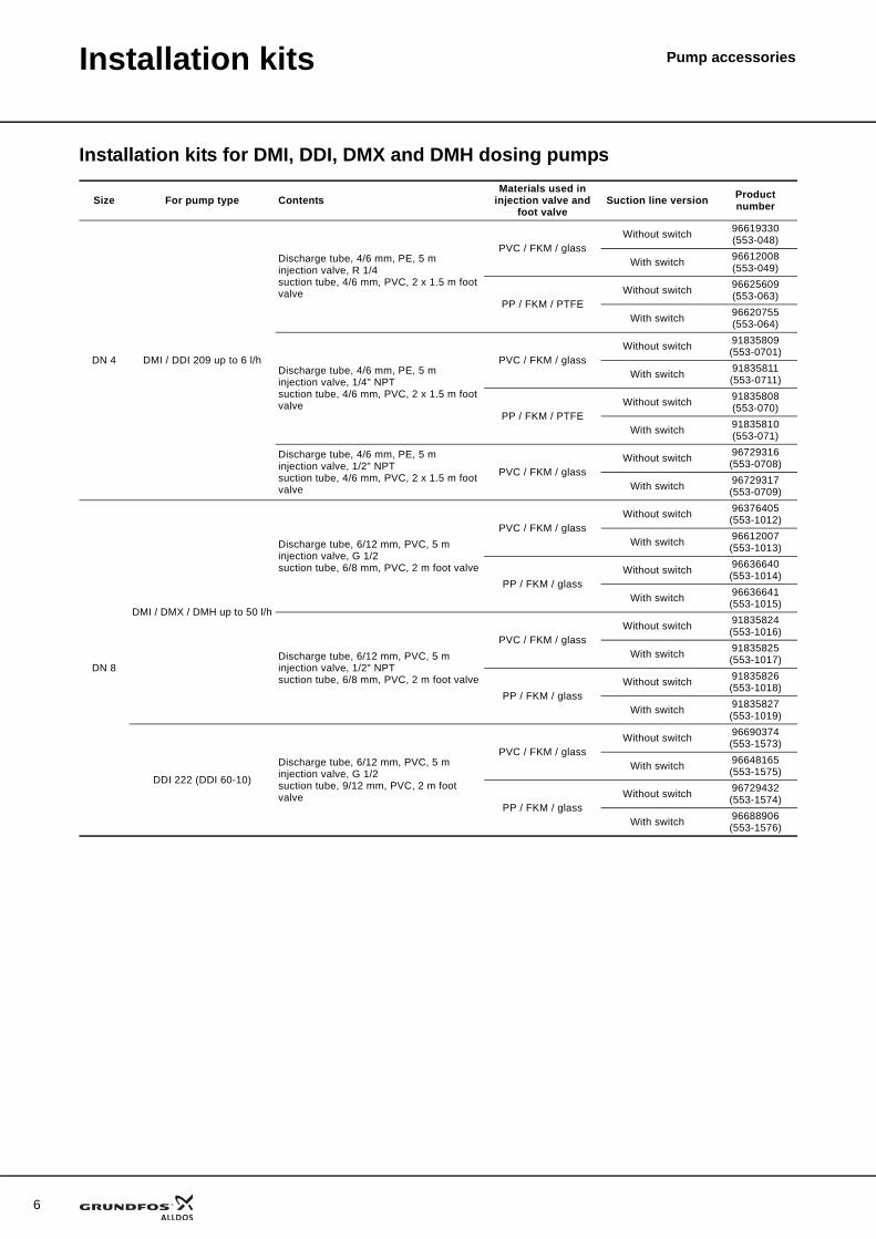
Installation kits for DMI, DDI, DMX and DMH dosing pumps
Size For pump type ContentsMaterials used in
injection valve and foot valve
Suction line version Product number
DN 4 DMI / DDI 209 up to 6 l/h
Discharge tube, 4/6 mm, PE, 5 minjection valve, R 1/4suction tube, 4/6 mm, PVC, 2 x 1.5 m foot valve
PVC / FKM / glassWithout switch 96619330
(553-048)
With switch 96612008(553-049)
PP / FKM / PTFEWithout switch 96625609
(553-063)
With switch 96620755(553-064)
Discharge tube, 4/6 mm, PE, 5 minjection valve, 1/4" NPTsuction tube, 4/6 mm, PVC, 2 x 1.5 m foot valve
PVC / FKM / glassWithout switch 91835809
(553-0701)
With switch 91835811(553-0711)
PP / FKM / PTFEWithout switch 91835808
(553-070)
With switch 91835810(553-071)
Discharge tube, 4/6 mm, PE, 5 minjection valve, 1/2" NPTsuction tube, 4/6 mm, PVC, 2 x 1.5 m foot valve
PVC / FKM / glassWithout switch 96729316
(553-0708)
With switch 96729317(553-0709)
DN 8
DMI / DMX / DMH up to 50 l/h
Discharge tube, 6/12 mm, PVC, 5 minjection valve, G 1/2suction tube, 6/8 mm, PVC, 2 m foot valve
PVC / FKM / glassWithout switch 96376405
(553-1012)
With switch 96612007(553-1013)
PP / FKM / glassWithout switch 96636640
(553-1014)
With switch 96636641(553-1015)
Discharge tube, 6/12 mm, PVC, 5 minjection valve, 1/2" NPTsuction tube, 6/8 mm, PVC, 2 m foot valve
PVC / FKM / glassWithout switch 91835824
(553-1016)
With switch 91835825(553-1017)
PP / FKM / glassWithout switch 91835826
(553-1018)
With switch 91835827(553-1019)
DDI 222 (DDI 60-10)
Discharge tube, 6/12 mm, PVC, 5 minjection valve, G 1/2suction tube, 9/12 mm, PVC, 2 m foot valve
PVC / FKM / glassWithout switch 96690374
(553-1573)
With switch 96648165(553-1575)
PP / FKM / glassWithout switch 96729432
(553-1574)
With switch 96688906(553-1576)
Pump accessoriesTubing
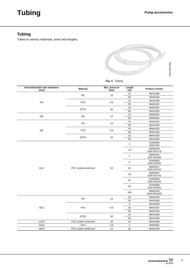
TubingTubes in various materials, sizes and lengths.
TM01
895
8 09
00
Fig. 4 Tubing
Internal/outside tube diameters[mm] Material Max. pressure
[bar]Length
[m] Product number
4/6
PE 1610 9644118850 96441190
PVC 0.510 9644118950 96441191
ETFE 2010 9644135150 96441352
5/8 PE 1310 9665566150 96655662
6/9
PE 1310 9644119250 96441195
PVC 0.510 9644119350 96441194
ETFE 2010 9644135350 96441354
6/12 PVC, textile-reinforced 23
1 91835682(526-022)
1.5 96699786(526-022/1.5)
3 96693751(526-022/03)
5 91835683(526-022/05)
10 96653571(526-022/10)
15 96693067(526-022/15)
25 91835685(526-022/25)
50 91835686(526-022/50)
100 96632340(526-022/100)
9/12
PE 1310 9644119650 96441198
PVC 0.52 96535083
10 9644119750 96441199
ETFE 2010 9644135550 96441356
12/19 PVC, textile-reinforced 15 10 9653448915/20 PVC 0.5 2 9653508116/24 PVC, textile-reinforced 14 10 96441200
7
8
Tubing Pump accessories
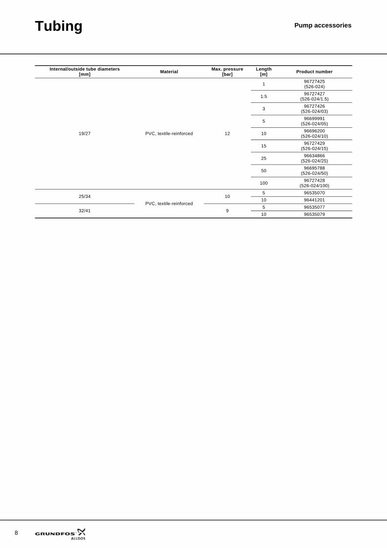
19/27 PVC, textile-reinforced 12
1 96727425(526-024)
1.5 96727427(526-024/1.5)
3 96727426(526-024/03)
5 96699991(526-024/05)
10 96696200(526-024/10)
15 96727429(526-024/15)
25 96634866(526-024/25)
50 96695788(526-024/50)
100 96727428(526-024/100)
25/34PVC, textile-reinforced
105 96535070
10 96441201
32/41 95 96535077
10 96535079
Internal/outside tube diameters[mm] Material Max. pressure
[bar]Length
[m] Product number
Pump accessoriesPump connections
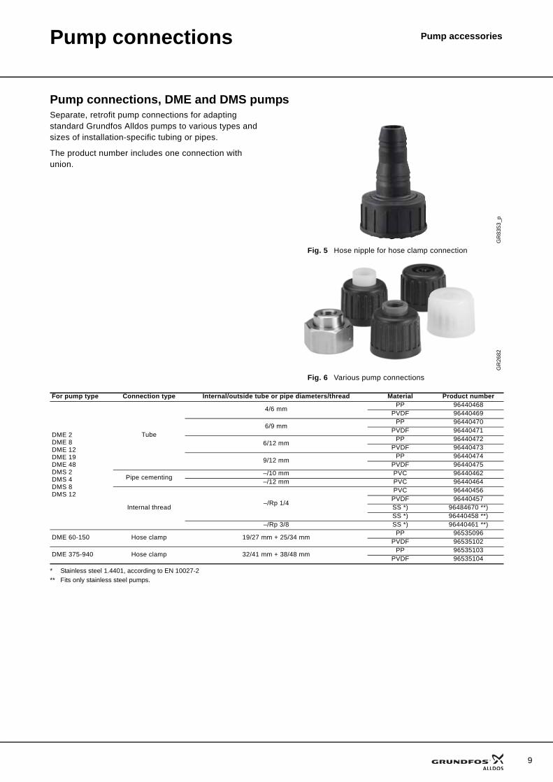
Pump connections, DME and DMS pumpsSeparate, retrofit pump connections for adapting standard Grundfos Alldos pumps to various types and sizes of installation-specific tubing or pipes.
The product number includes one connection with union.
* Stainless steel 1.4401, according to EN 10027-2** Fits only stainless steel pumps.
GR
8353
_p
Fig. 5 Hose nipple for hose clamp connection
GR
2682
Fig. 6 Various pump connections
For pump type Connection type Internal/outside tube or pipe diameters/thread Material Product number
DME 2DME 8DME 12DME 19DME 48DMS 2DMS 4DMS 8DMS 12
Tube
4/6 mm PP 96440468PVDF 96440469
6/9 mm PP 96440470PVDF 96440471
6/12 mm PP 96440472PVDF 96440473
9/12 mm PP 96440474PVDF 96440475
Pipe cementing –/10 mm PVC 96440462–/12 mm PVC 96440464
Internal thread –/Rp 1/4
PVC 96440456PVDF 96440457SS *) 96484670 **)SS *) 96440458 **)
–/Rp 3/8 SS *) 96440461 **)
DME 60-150 Hose clamp 19/27 mm + 25/34 mm PP 96535096PVDF 96535102
DME 375-940 Hose clamp 32/41 mm + 38/48 mm PP 96535103PVDF 96535104
9
10
Pump connections Pump accessories
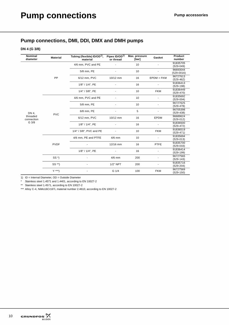
Pump connections, DMI, DDI, DMX and DMH pumpsDN 4 (G 3/8)
1) ID = Internal Diameter, OD = Outside Diameter* Stainless steel 1.4571 and 1.4401, according to EN 10027-2** Stainless steel 1.4571, according to EN 10027-2*** Alloy C-4, NiMo16Cr16Ti, material number 2.4610, according to EN 10027-2
Nominal diameter Material Tubing (flexible) ID/OD1),
materialPipes ID/OD1)
or threadMax. pressure
[bar] Gasket Product number
DN 4,threaded
connection G 3/8
PP
4/6 mm, PVC and PE - 10 - 91835705(529-049)
5/8 mm, PE - 10 - 96693044(529-0016)
6/12 mm, PVC 10/12 mm 16 EPDM + FKM 96727613(529-462)
1/8" / 1/4", PE - 16 - 91836413(529-198)
1/4" / 3/8", PE - 10 FKM 91836449(529-470)
PVC
4/6 mm, PVC and PE - 10 - 91835692(529-004)
5/8 mm, PE - 10 - 96727625(529-478)
6/8 mm, PE - 5 - 96705398(529-438)
6/12 mm, PVC 10/12 mm 16 EPDM 96689624(529-012)
1/8" / 1/4", PE - 16 - 91836500(529-472)
1/4" / 3/8", PVC and PE - 10 FKM 91836519(529-471)
PVDF
4/6 mm, PE and PTFE 4/6 mm 10 - 91835694(529-013)
- 12/16 mm 16 PTFE 91835700(529-033)
1/8" / 1/4", PE - 16 - 91836414(529-199)
SS *) - 4/6 mm 200 - 96727565(529-143)
SS **) - 1/2" NPT 200 - 91835716(529-204)
Y ***) - G 1/4 100 FKM 96727569(529-150)
Pump connections Pump accessories
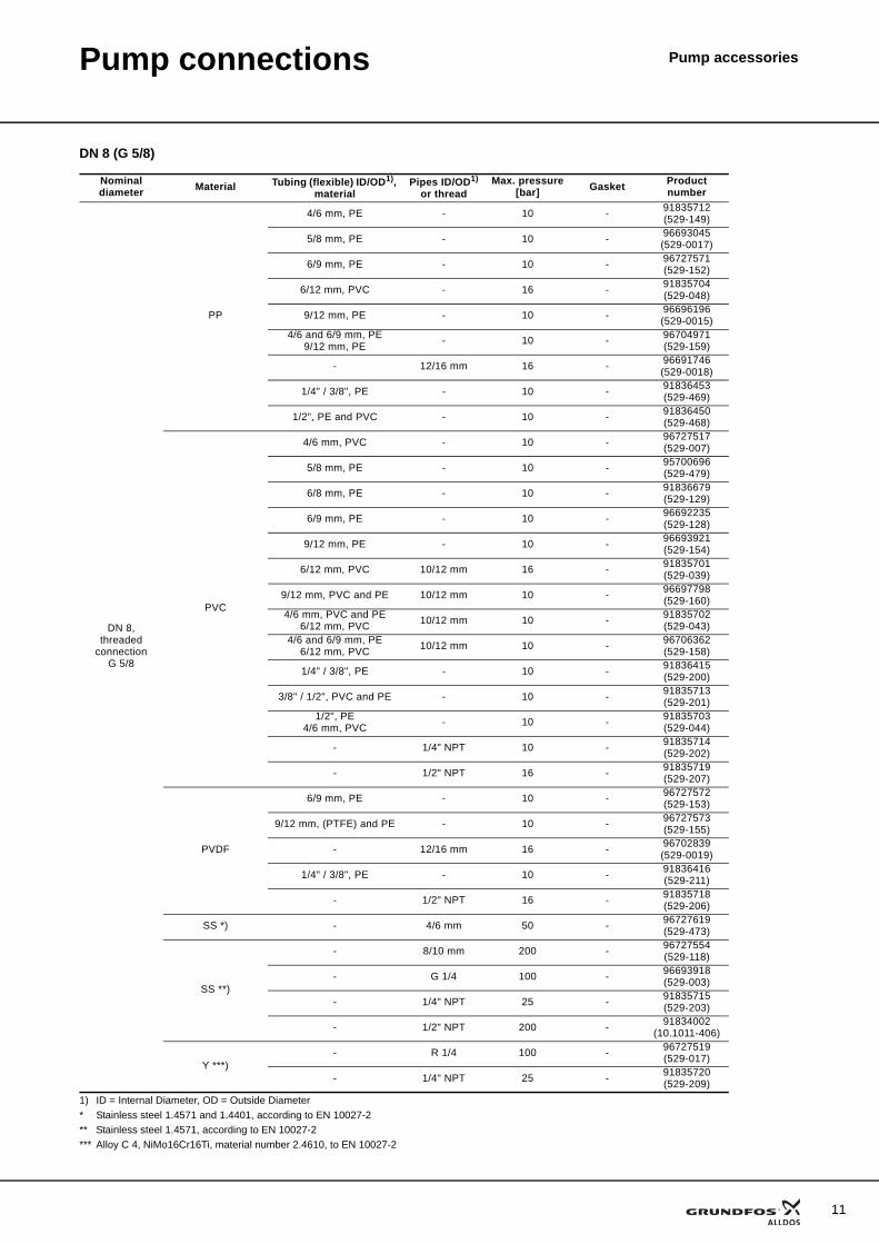
DN 8 (G 5/8)
1) ID = Internal Diameter, OD = Outside Diameter * Stainless steel 1.4571 and 1.4401, according to EN 10027-2** Stainless steel 1.4571, according to EN 10027-2*** Alloy C 4, NiMo16Cr16Ti, material number 2.4610, to EN 10027-2
Nominal diameter Material Tubing (flexible) ID/OD1),
materialPipes ID/OD1)
or threadMax. pressure
[bar] Gasket Product number
DN 8,threaded
connection G 5/8
PP
4/6 mm, PE - 10 - 91835712(529-149)
5/8 mm, PE - 10 - 96693045(529-0017)
6/9 mm, PE - 10 - 96727571(529-152)
6/12 mm, PVC - 16 - 91835704(529-048)
9/12 mm, PE - 10 - 96696196(529-0015)
4/6 and 6/9 mm, PE9/12 mm, PE - 10 - 96704971
(529-159)
- 12/16 mm 16 - 96691746(529-0018)
1/4" / 3/8", PE - 10 - 91836453(529-469)
1/2", PE and PVC - 10 - 91836450(529-468)
PVC
4/6 mm, PVC - 10 - 96727517(529-007)
5/8 mm, PE - 10 - 95700696(529-479)
6/8 mm, PE - 10 - 91836679(529-129)
6/9 mm, PE - 10 - 96692235(529-128)
9/12 mm, PE - 10 - 96693921(529-154)
6/12 mm, PVC 10/12 mm 16 - 91835701(529-039)
9/12 mm, PVC and PE 10/12 mm 10 - 96697798(529-160)
4/6 mm, PVC and PE6/12 mm, PVC 10/12 mm 10 - 91835702
(529-043)4/6 and 6/9 mm, PE
6/12 mm, PVC 10/12 mm 10 - 96706362(529-158)
1/4" / 3/8", PE - 10 - 91836415(529-200)
3/8" / 1/2", PVC and PE - 10 - 91835713(529-201)
1/2", PE4/6 mm, PVC - 10 - 91835703
(529-044)
- 1/4" NPT 10 - 91835714(529-202)
- 1/2" NPT 16 - 91835719(529-207)
PVDF
6/9 mm, PE - 10 - 96727572(529-153)
9/12 mm, (PTFE) and PE - 10 - 96727573(529-155)
- 12/16 mm 16 - 96702839(529-0019)
1/4" / 3/8", PE - 10 - 91836416(529-211)
- 1/2" NPT 16 - 91835718(529-206)
SS *) - 4/6 mm 50 - 96727619(529-473)
SS **)
- 8/10 mm 200 - 96727554(529-118)
- G 1/4 100 - 96693918(529-003)
- 1/4" NPT 25 - 91835715(529-203)
- 1/2" NPT 200 - 91834002(10.1011-406)
Y ***)- R 1/4 100 - 96727519
(529-017)
- 1/4" NPT 25 - 91835720(529-209)
11
12
Pump connections Pump accessories
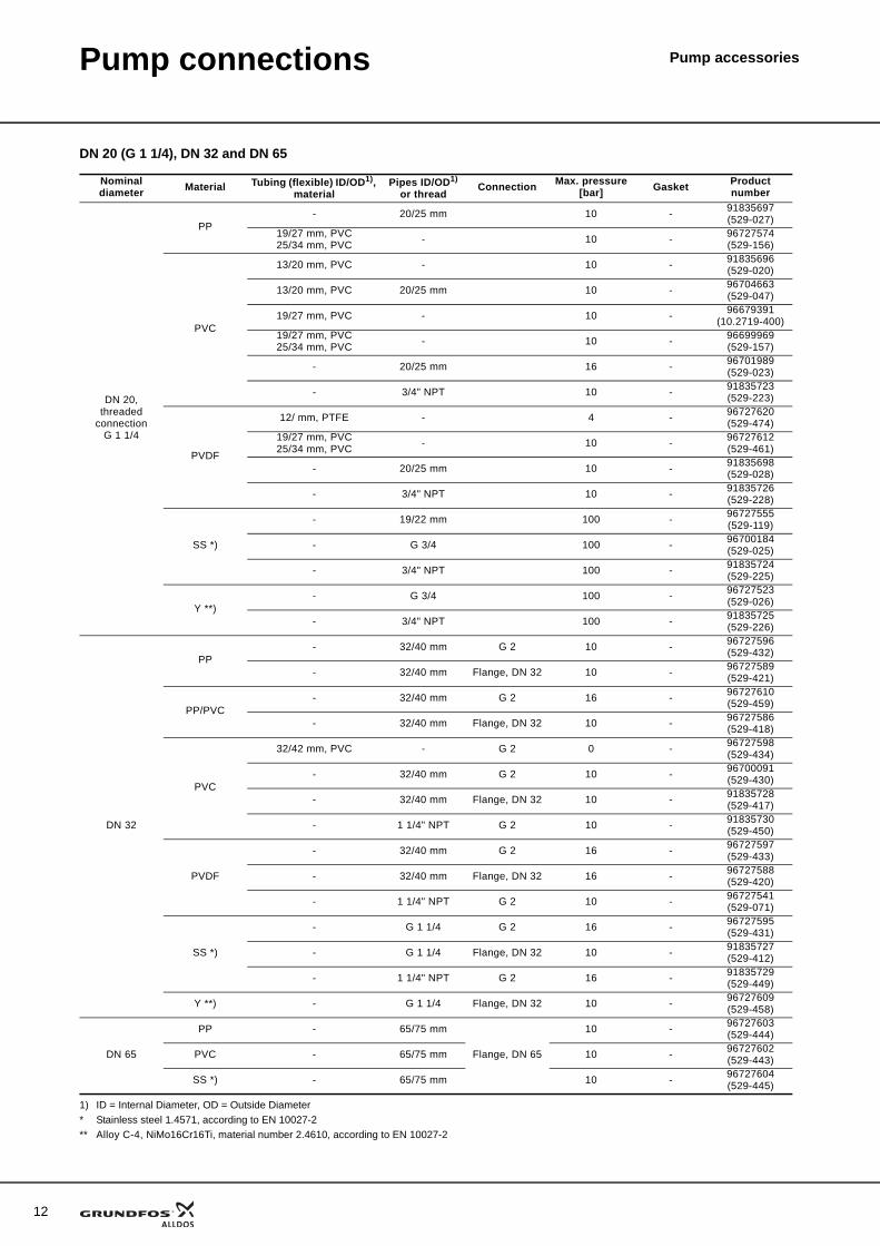
DN 20 (G 1 1/4), DN 32 and DN 65
1) ID = Internal Diameter, OD = Outside Diameter* Stainless steel 1.4571, according to EN 10027-2** Alloy C-4, NiMo16Cr16Ti, material number 2.4610, according to EN 10027-2
Nominal diameter Material Tubing (flexible) ID/OD1),
materialPipes ID/OD1)
or threadConnection Max. pressure
[bar] Gasket Product number
DN 20,threaded
connection G 1 1/4
PP- 20/25 mm 10 - 91835697
(529-027)19/27 mm, PVC25/34 mm, PVC - 10 - 96727574
(529-156)
PVC
13/20 mm, PVC - 10 - 91835696(529-020)
13/20 mm, PVC 20/25 mm 10 - 96704663(529-047)
19/27 mm, PVC - 10 - 96679391(10.2719-400)
19/27 mm, PVC25/34 mm, PVC - 10 - 96699969
(529-157)
- 20/25 mm 16 - 96701989(529-023)
- 3/4" NPT 10 - 91835723(529-223)
PVDF
12/ mm, PTFE - 4 - 96727620(529-474)
19/27 mm, PVC25/34 mm, PVC - 10 - 96727612
(529-461)
- 20/25 mm 10 - 91835698(529-028)
- 3/4" NPT 10 - 91835726(529-228)
SS *)
- 19/22 mm 100 - 96727555(529-119)
- G 3/4 100 - 96700184(529-025)
- 3/4" NPT 100 - 91835724(529-225)
Y **)- G 3/4 100 - 96727523
(529-026)
- 3/4" NPT 100 - 91835725(529-226)
DN 32
PP- 32/40 mm G 2 10 - 96727596
(529-432)
- 32/40 mm Flange, DN 32 10 - 96727589(529-421)
PP/PVC- 32/40 mm G 2 16 - 96727610
(529-459)
- 32/40 mm Flange, DN 32 10 - 96727586(529-418)
PVC
32/42 mm, PVC - G 2 0 - 96727598(529-434)
- 32/40 mm G 2 10 - 96700091(529-430)
- 32/40 mm Flange, DN 32 10 - 91835728(529-417)
- 1 1/4" NPT G 2 10 - 91835730(529-450)
PVDF
- 32/40 mm G 2 16 - 96727597(529-433)
- 32/40 mm Flange, DN 32 16 - 96727588(529-420)
- 1 1/4" NPT G 2 10 - 96727541(529-071)
SS *)
- G 1 1/4 G 2 16 - 96727595(529-431)
- G 1 1/4 Flange, DN 32 10 - 91835727(529-412)
- 1 1/4" NPT G 2 16 - 91835729(529-449)
Y **) - G 1 1/4 Flange, DN 32 10 - 96727609(529-458)
DN 65
PP - 65/75 mm
Flange, DN 65
10 - 96727603(529-444)
PVC - 65/75 mm 10 - 96727602(529-443)
SS *) - 65/75 mm 10 - 96727604(529-445)
Pump connections Pump accessories
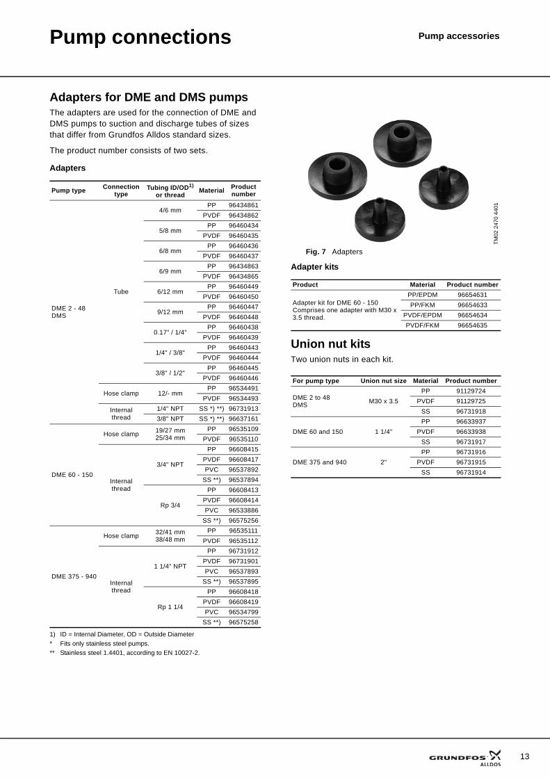
Adapters for DME and DMS pumpsThe adapters are used for the connection of DME and DMS pumps to suction and discharge tubes of sizes that differ from Grundfos Alldos standard sizes.
The product number consists of two sets.
Adapters
1) ID = Internal Diameter, OD = Outside Diameter* Fits only stainless steel pumps.** Stainless steel 1.4401, according to EN 10027-2.
Adapter kits
Union nut kitsTwo union nuts in each kit.
Pump type Connection type
Tubing ID/OD1)
or threadMaterial Product
number
DME 2 - 48DMS
Tube
4/6 mmPP 96434861
PVDF 96434862
5/8 mmPP 96460434
PVDF 96460435
6/8 mmPP 96460436
PVDF 96460437
6/9 mmPP 96434863
PVDF 96434865
6/12 mmPP 96460449
PVDF 96460450
9/12 mmPP 96460447
PVDF 96460448
0.17" / 1/4"PP 96460438
PVDF 96460439
1/4" / 3/8"PP 96460443
PVDF 96460444
3/8" / 1/2"PP 96460445
PVDF 96460446
Hose clamp 12/- mmPP 96534491
PVDF 96534493
Internal thread
1/4" NPT SS *) **) 967319133/8" NPT SS *) **) 96637161
DME 60 - 150
Hose clamp 19/27 mm25/34 mm
PP 96535109PVDF 96535110
Internal thread
3/4" NPT
PP 96608415PVDF 96608417PVC 96537892
SS **) 96537894
Rp 3/4
PP 96608413PVDF 96608414PVC 96533886
SS **) 96575256
DME 375 - 940
Hose clamp 32/41 mm38/48 mm
PP 96535111PVDF 96535112
Internal thread
1 1/4" NPT
PP 96731912PVDF 96731901PVC 96537893
SS **) 96537895
Rp 1 1/4
PP 96608418PVDF 96608419PVC 96534799
SS **) 96575258
TM02
247
0 44
01
Fig. 7 Adapters
Product Material Product number
Adapter kit for DME 60 - 150Comprises one adapter with M30 x 3.5 thread.
PP/EPDM 96654631PP/FKM 96654633
PVDF/EPDM 96654634PVDF/FKM 96654635
For pump type Union nut size Material Product number
DME 2 to 48DMS M30 x 3.5
PP 91129724PVDF 91129725
SS 96731918
DME 60 and 150 1 1/4"PP 96633937
PVDF 96633938SS 96731917
DME 375 and 940 2"PP 96731916
PVDF 96731915SS 96731914
13
Pump accessories
14
Foot valves
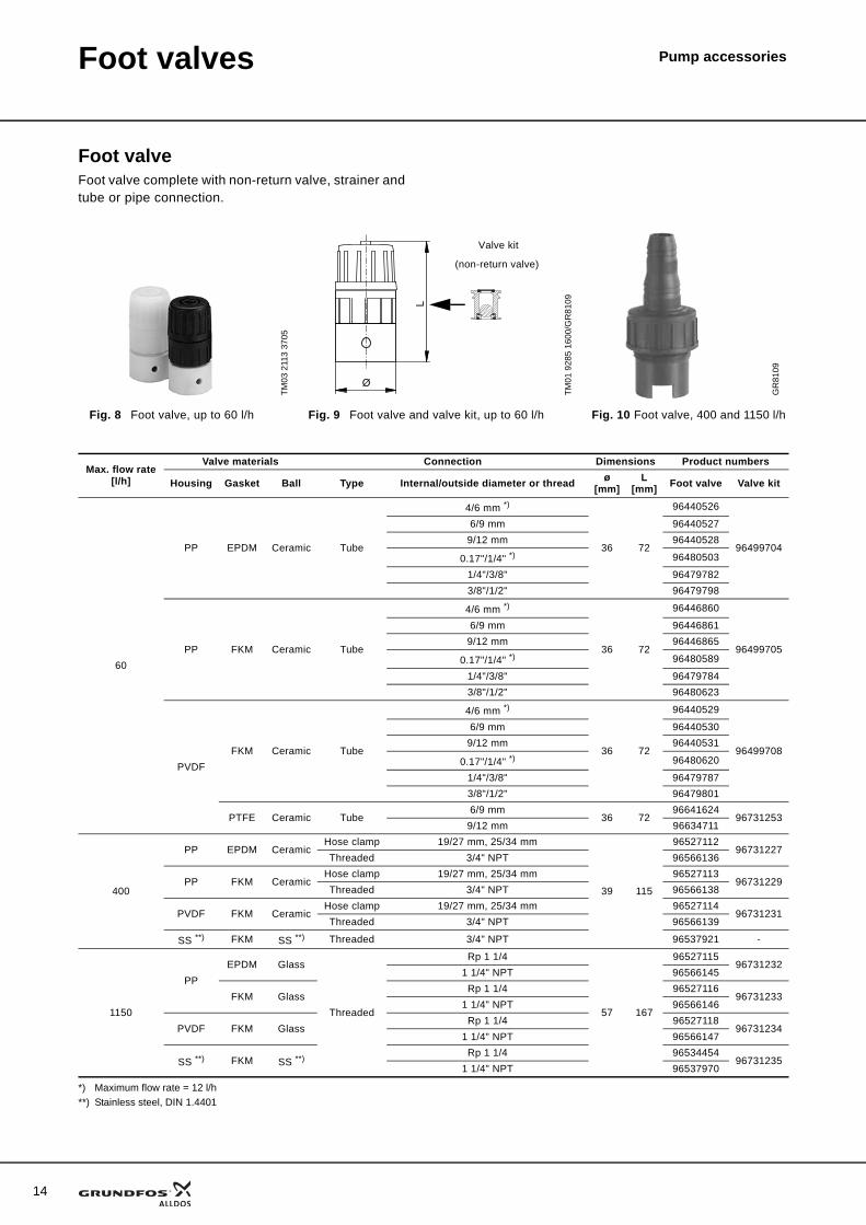
Foot valveFoot valve complete with non-return valve, strainer and tube or pipe connection.
*) Maximum flow rate = 12 l/h**) Stainless steel, DIN 1.4401
TM03
211
3 37
05
TM01
928
5 16
00/G
R81
09
GR
8109
Fig. 8 Foot valve, up to 60 l/h Fig. 9 Foot valve and valve kit, up to 60 l/h Fig. 10 Foot valve, 400 and 1150 l/h
(non-return valve)
Valve kit
Max. flow rate[l/h]
Valve materials Connection Dimensions Product numbers
Housing Gasket Ball Type Internal/outside diameter or thread ø[mm]
L[mm] Foot valve Valve kit
60
PP EPDM Ceramic Tube
4/6 mm *)
36 72
96440526
96499704
6/9 mm 964405279/12 mm 96440528
0.17"/1/4" *) 96480503
1/4"/3/8" 964797823/8"/1/2" 96479798
PP FKM Ceramic Tube
4/6 mm *)
36 72
96446860
96499705
6/9 mm 964468619/12 mm 96446865
0.17"/1/4" *) 96480589
1/4"/3/8" 964797843/8"/1/2" 96480623
PVDFFKM Ceramic Tube
4/6 mm *)
36 72
96440529
96499708
6/9 mm 964405309/12 mm 96440531
0.17"/1/4" *) 96480620
1/4"/3/8" 964797873/8"/1/2" 96479801
PTFE Ceramic Tube6/9 mm
36 7296641624
967312539/12 mm 96634711
400
PP EPDM CeramicHose clamp 19/27 mm, 25/34 mm
39 115
9652711296731227
Threaded 3/4" NPT 96566136
PP FKM CeramicHose clamp 19/27 mm, 25/34 mm 96527113
96731229Threaded 3/4" NPT 96566138
PVDF FKM CeramicHose clamp 19/27 mm, 25/34 mm 96527114
96731231Threaded 3/4" NPT 96566139
SS **) FKM SS **) Threaded 3/4" NPT 96537921 -
1150
PPEPDM Glass
Threaded
Rp 1 1/4
57 167
9652711596731232
1 1/4" NPT 96566145
FKM GlassRp 1 1/4 96527116
967312331 1/4" NPT 96566146
PVDF FKM GlassRp 1 1/4 96527118
967312341 1/4" NPT 96566147
SS **) FKM SS **) Rp 1 1/4 9653445496731235
1 1/4" NPT 96537970
Pump accessoriesSuction lines
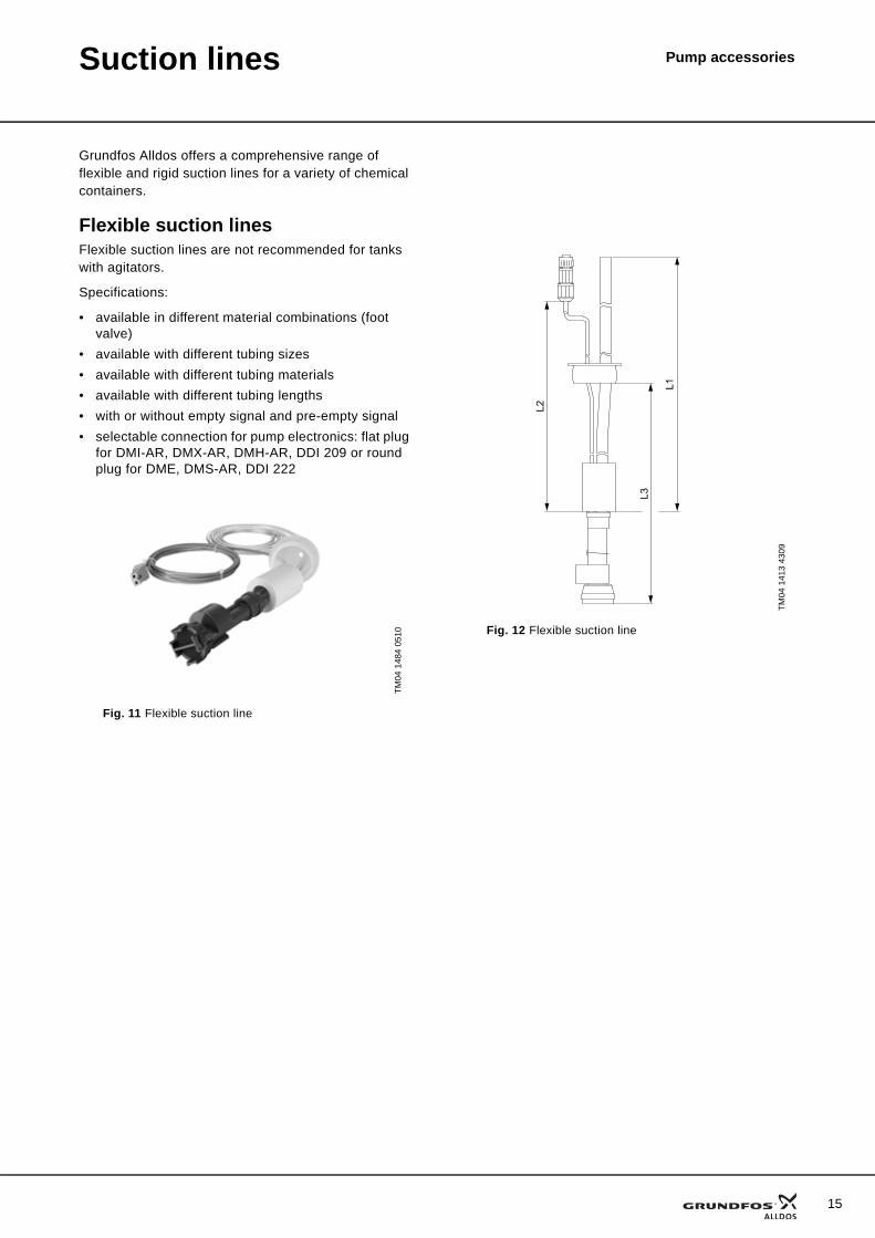
Grundfos Alldos offers a comprehensive range of flexible and rigid suction lines for a variety of chemical containers.
Flexible suction linesFlexible suction lines are not recommended for tanks with agitators.
Specifications:
• available in different material combinations (foot valve)
• available with different tubing sizes• available with different tubing materials• available with different tubing lengths• with or without empty signal and pre-empty signal• selectable connection for pump electronics: flat plug
for DMI-AR, DMX-AR, DMH-AR, DDI 209 or round plug for DME, DMS-AR, DDI 222
TM04
148
4 05
10
Fig. 11 Flexible suction line
TM04
141
3 43
09
Fig. 12 Flexible suction line
L2
L3
L1
15
16
Suction lines Pump accessories
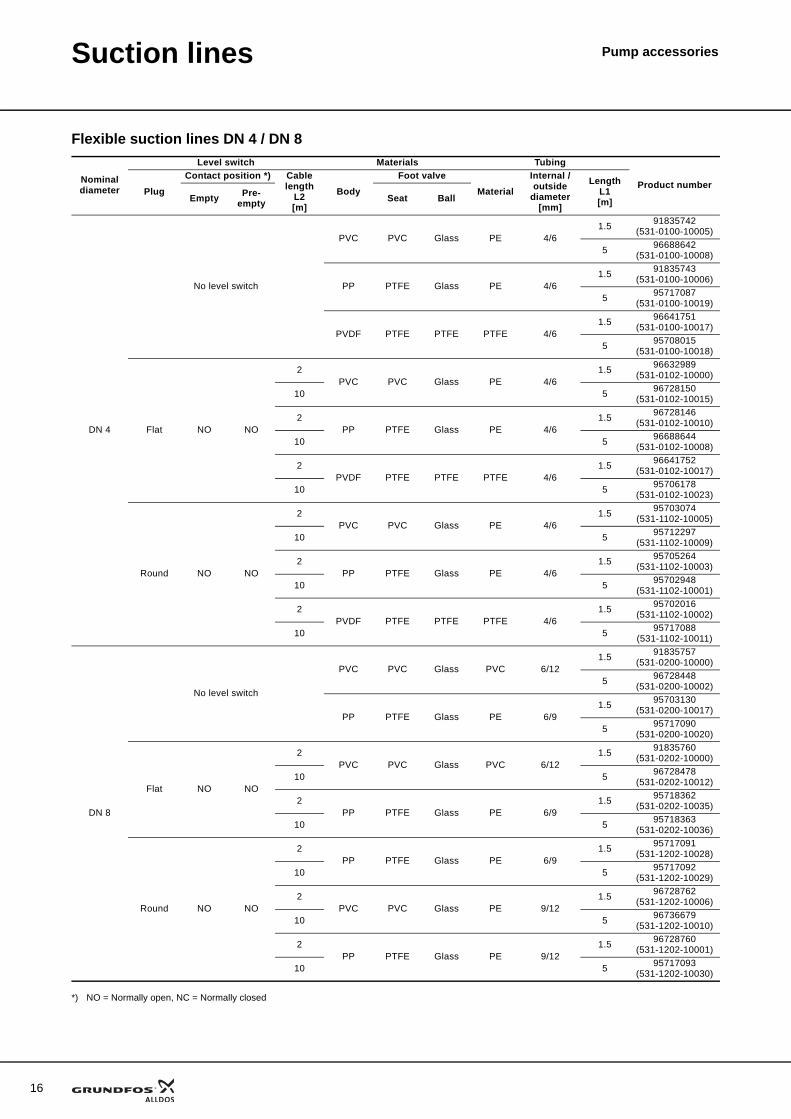
Flexible suction lines DN 4 / DN 8
*) NO = Normally open, NC = Normally closed
Nominal diameter
Level switch Materials Tubing
Product numberPlug
Contact position *) Cable length
L2[m]
BodyFoot valve
MaterialInternal / outside
diameter[mm]
LengthL1[m]Empty Pre-
empty Seat Ball
DN 4
No level switch
PVC PVC Glass PE 4/61.5 91835742
(531-0100-10005)
5 96688642(531-0100-10008)
PP PTFE Glass PE 4/61.5 91835743
(531-0100-10006)
5 95717087(531-0100-10019)
PVDF PTFE PTFE PTFE 4/61.5 96641751
(531-0100-10017)
5 95708015(531-0100-10018)
Flat NO NO
2PVC PVC Glass PE 4/6
1.5 96632989(531-0102-10000)
10 5 96728150(531-0102-10015)
2PP PTFE Glass PE 4/6
1.5 96728146(531-0102-10010)
10 5 96688644(531-0102-10008)
2PVDF PTFE PTFE PTFE 4/6
1.5 96641752(531-0102-10017)
10 5 95706178(531-0102-10023)
Round NO NO
2PVC PVC Glass PE 4/6
1.5 95703074(531-1102-10005)
10 5 95712297(531-1102-10009)
2PP PTFE Glass PE 4/6
1.5 95705264(531-1102-10003)
10 5 95702948(531-1102-10001)
2PVDF PTFE PTFE PTFE 4/6
1.5 95702016(531-1102-10002)
10 5 95717088(531-1102-10011)
DN 8
No level switch
PVC PVC Glass PVC 6/121.5 91835757
(531-0200-10000)
5 96728448(531-0200-10002)
PP PTFE Glass PE 6/91.5 95703130
(531-0200-10017)
5 95717090(531-0200-10020)
Flat NO NO
2PVC PVC Glass PVC 6/12
1.5 91835760(531-0202-10000)
10 5 96728478(531-0202-10012)
2PP PTFE Glass PE 6/9
1.5 95718362(531-0202-10035)
10 5 95718363(531-0202-10036)
Round NO NO
2PP PTFE Glass PE 6/9
1.5 95717091(531-1202-10028)
10 5 95717092(531-1202-10029)
2PVC PVC Glass PE 9/12
1.5 96728762(531-1202-10006)
10 5 96736679(531-1202-10010)
2PP PTFE Glass PE 9/12
1.5 96728760(531-1202-10001)
10 5 95717093(531-1202-10030)
Suction lines Pump accessories
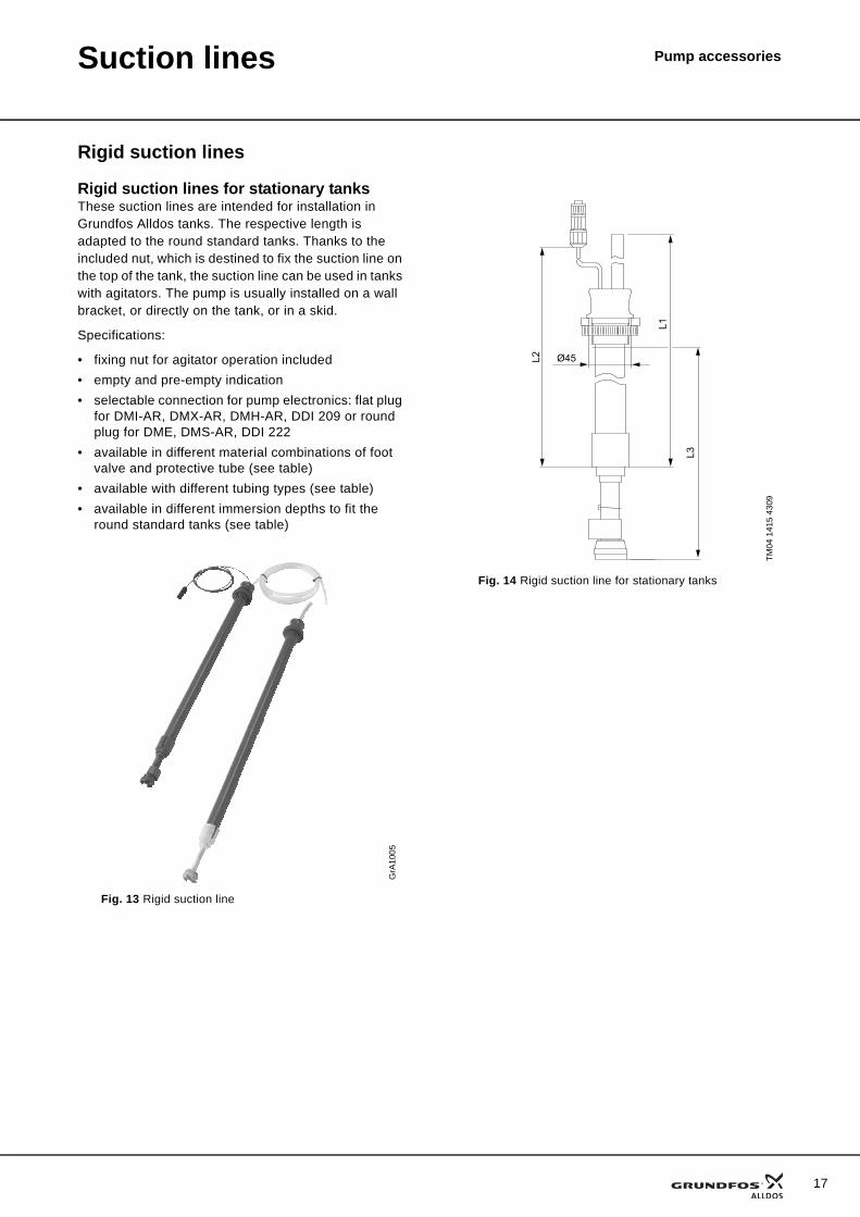
Rigid suction lines
Rigid suction lines for stationary tanksThese suction lines are intended for installation in Grundfos Alldos tanks. The respective length is adapted to the round standard tanks. Thanks to the included nut, which is destined to fix the suction line on the top of the tank, the suction line can be used in tanks with agitators. The pump is usually installed on a wall bracket, or directly on the tank, or in a skid.
Specifications:
• fixing nut for agitator operation included• empty and pre-empty indication• selectable connection for pump electronics: flat plug
for DMI-AR, DMX-AR, DMH-AR, DDI 209 or round plug for DME, DMS-AR, DDI 222
• available in different material combinations of foot valve and protective tube (see table)
• available with different tubing types (see table)• available in different immersion depths to fit the
round standard tanks (see table)
GrA
1005
Fig. 13 Rigid suction line
TM04
141
5 43
09
Fig. 14 Rigid suction line for stationary tanks
L2
L3
L1
Ø45
17
18
Suction lines Pump accessories
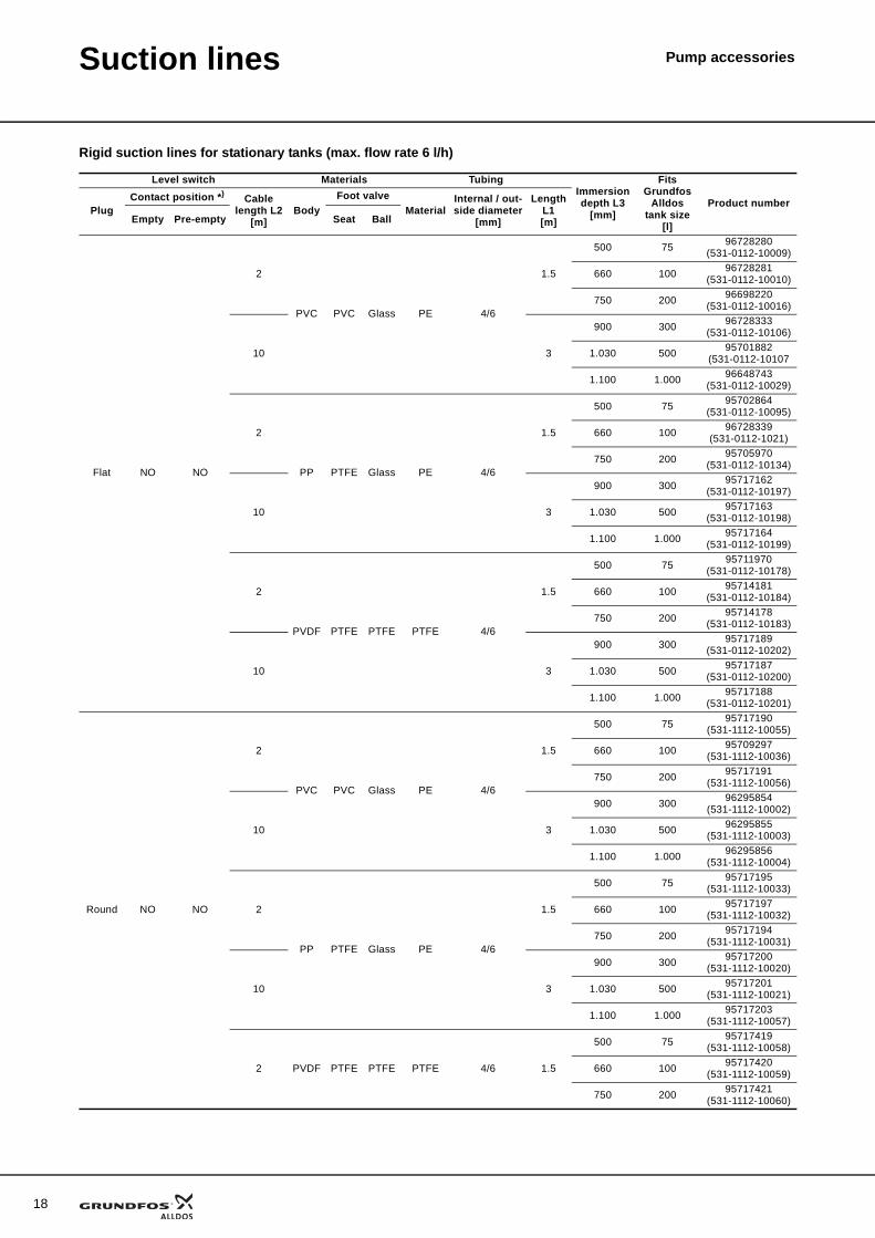
Rigid suction lines for stationary tanks (max. flow rate 6 l/h)
Level switch Materials TubingImmersion depth L3
[mm]
Fits Grundfos
Alldos tank size
[l]
Product numberPlug
Contact position *) Cable length L2
[m]Body
Foot valveMaterial
Internal / out-side diameter
[mm]
LengthL1[m]Empty Pre-empty Seat Ball
Flat NO NO
2
PVC PVC Glass PE 4/6
1.5
500 75 96728280(531-0112-10009)
660 100 96728281(531-0112-10010)
750 200 96698220(531-0112-10016)
10 3
900 300 96728333(531-0112-10106)
1.030 500 95701882(531-0112-10107
1.100 1.000 96648743(531-0112-10029)
2
PP PTFE Glass PE 4/6
1.5
500 75 95702864(531-0112-10095)
660 100 96728339(531-0112-1021)
750 200 95705970(531-0112-10134)
10 3
900 300 95717162(531-0112-10197)
1.030 500 95717163(531-0112-10198)
1.100 1.000 95717164(531-0112-10199)
2
PVDF PTFE PTFE PTFE 4/6
1.5
500 75 95711970(531-0112-10178)
660 100 95714181(531-0112-10184)
750 200 95714178(531-0112-10183)
10 3
900 300 95717189(531-0112-10202)
1.030 500 95717187(531-0112-10200)
1.100 1.000 95717188(531-0112-10201)
Round NO NO
2
PVC PVC Glass PE 4/6
1.5
500 75 95717190(531-1112-10055)
660 100 95709297(531-1112-10036)
750 200 95717191(531-1112-10056)
10 3
900 300 96295854(531-1112-10002)
1.030 500 96295855(531-1112-10003)
1.100 1.000 96295856(531-1112-10004)
2
PP PTFE Glass PE 4/6
1.5
500 75 95717195(531-1112-10033)
660 100 95717197(531-1112-10032)
750 200 95717194(531-1112-10031)
10 3
900 300 95717200(531-1112-10020)
1.030 500 95717201(531-1112-10021)
1.100 1.000 95717203(531-1112-10057)
2 PVDF PTFE PTFE PTFE 4/6 1.5
500 75 95717419(531-1112-10058)
660 100 95717420(531-1112-10059)
750 200 95717421(531-1112-10060)
Suction lines Pump accessories
*) NO = Normally Open, NC = Normally Closed
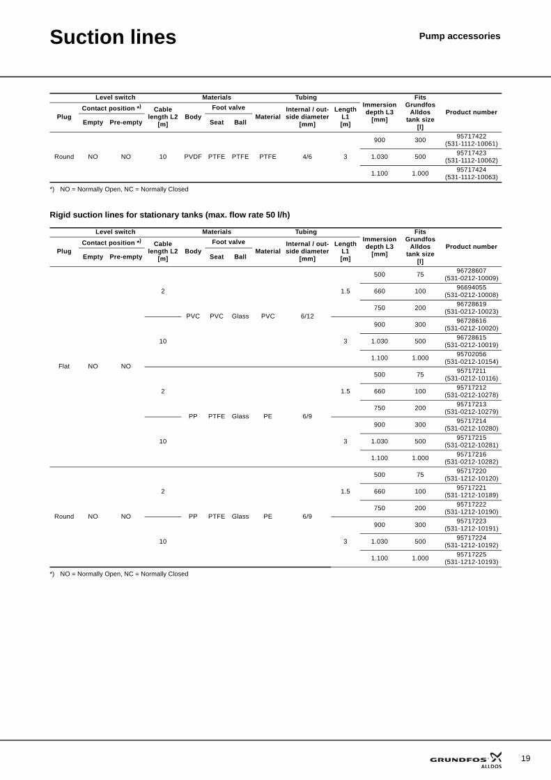
Rigid suction lines for stationary tanks (max. flow rate 50 l/h)
*) NO = Normally Open, NC = Normally Closed
Round NO NO 10 PVDF PTFE PTFE PTFE 4/6 3
900 300 95717422(531-1112-10061)
1.030 500 95717423(531-1112-10062)
1.100 1.000 95717424(531-1112-10063)
Level switch Materials TubingImmersion depth L3
[mm]
Fits Grundfos
Alldos tank size
[l]
Product numberPlug
Contact position *) Cable length L2
[m]Body
Foot valveMaterial
Internal / out-side diameter
[mm]
LengthL1[m]Empty Pre-empty Seat Ball
Level switch Materials TubingImmersion depth L3
[mm]
Fits Grundfos
Alldos tank size
[l]
Product numberPlug
Contact position *) Cable length L2
[m]Body
Foot valveMaterial
Internal / out-side diameter
[mm]
LengthL1[m]Empty Pre-empty Seat Ball
Flat NO NO
2
PVC PVC Glass PVC 6/12
1.5
500 75 96728607(531-0212-10009)
660 100 96694055(531-0212-10008)
750 200 96728619(531-0212-10023)
10 3
900 300 96728616(531-0212-10020)
1.030 500 96728615(531-0212-10019)
1.100 1.000 95702056(531-0212-10154)
2
PP PTFE Glass PE 6/9
1.5
500 75 95717211(531-0212-10116)
660 100 95717212(531-0212-10278)
750 200 95717213(531-0212-10279)
10 3
900 300 95717214(531-0212-10280)
1.030 500 95717215(531-0212-10281)
1.100 1.000 95717216(531-0212-10282)
Round NO NO
2
PP PTFE Glass PE 6/9
1.5
500 75 95717220(531-1212-10120)
660 100 95717221(531-1212-10189)
750 200 95717222(531-1212-10190)
10 3
900 300 95717223(531-1212-10191)
1.030 500 95717224(531-1212-10192)
1.100 1.000 95717225(531-1212-10193)
19
20
Suction lines Pump accessories
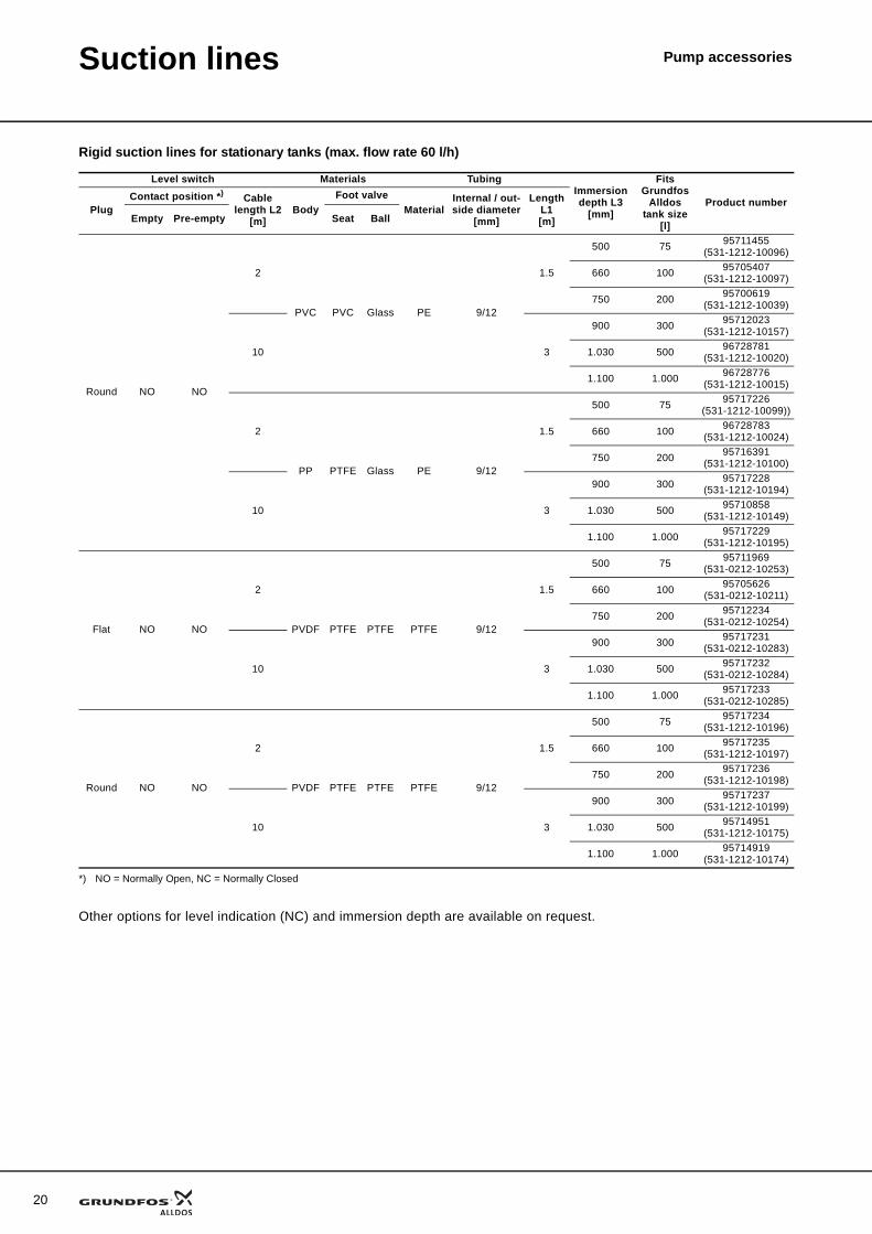
Rigid suction lines for stationary tanks (max. flow rate 60 l/h)
*) NO = Normally Open, NC = Normally Closed
Other options for level indication (NC) and immersion depth are available on request.
Level switch Materials TubingImmersion depth L3
[mm]
Fits Grundfos
Alldos tank size
[l]
Product numberPlug
Contact position *) Cable length L2
[m]Body
Foot valveMaterial
Internal / out-side diameter
[mm]
LengthL1[m]Empty Pre-empty Seat Ball
Round NO NO
2
PVC PVC Glass PE 9/12
1.5
500 75 95711455(531-1212-10096)
660 100 95705407(531-1212-10097)
750 200 95700619(531-1212-10039)
10 3
900 300 95712023(531-1212-10157)
1.030 500 96728781(531-1212-10020)
1.100 1.000 96728776(531-1212-10015)
2
PP PTFE Glass PE 9/12
1.5
500 75 95717226(531-1212-10099))
660 100 96728783(531-1212-10024)
750 200 95716391(531-1212-10100)
10 3
900 300 95717228(531-1212-10194)
1.030 500 95710858(531-1212-10149)
1.100 1.000 95717229(531-1212-10195)
Flat NO NO
2
PVDF PTFE PTFE PTFE 9/12
1.5
500 75 95711969(531-0212-10253)
660 100 95705626(531-0212-10211)
750 200 95712234(531-0212-10254)
10 3
900 300 95717231(531-0212-10283)
1.030 500 95717232(531-0212-10284)
1.100 1.000 95717233(531-0212-10285)
Round NO NO
2
PVDF PTFE PTFE PTFE 9/12
1.5
500 75 95717234(531-1212-10196)
660 100 95717235(531-1212-10197)
750 200 95717236(531-1212-10198)
10 3
900 300 95717237(531-1212-10199)
1.030 500 95714951(531-1212-10175)
1.100 1.000 95714919(531-1212-10174)
Suction lines Pump accessories
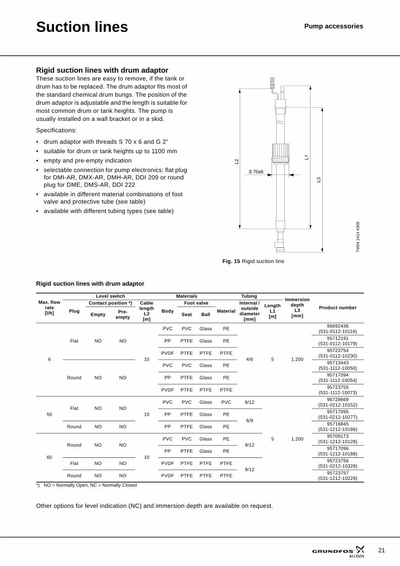
Rigid suction lines with drum adaptorThese suction lines are easy to remove, if the tank or drum has to be replaced. The drum adaptor fits most of the standard chemical drum bungs. The position of the drum adaptor is adjustable and the length is suitable for most common drum or tank heights. The pump is usually installed on a wall bracket or in a skid.
Specifications:
• drum adaptor with threads S 70 x 6 and G 2”• suitable for drum or tank heights up to 1100 mm• empty and pre-empty indication• selectable connection for pump electronics: flat plug
for DMI-AR, DMX-AR, DMH-AR, DDI 209 or round plug for DME, DMS-AR, DDI 222
• available in different material combinations of foot valve and protective tube (see table)
• available with different tubing types (see table)
Rigid suction lines with drum adaptor
Other options for level indication (NC) and immersion depth are available on request.
TM04
141
4 43
09
Fig. 15 Rigid suction line
L2
L3
S 70x6
L1Max. flow
rate[l/h]
Level switch Materials TubingImmersion
depthL3
[mm]Product number
PlugContact position *) Cable
lengthL2[m]
BodyFoot valve
MaterialInternal / outside
diameter[mm]
LengthL1[m]Empty Pre-
empty Seat Ball
6
Flat NO NO
10
PVC PVC Glass PE
4/6 5 1.200
96692436(531-0112-10116)
PP PTFE Glass PE 95712191(531-0112-10179)
PVDF PTFE PTFE PTFE 95723754(531-0112-10230)
Round NO NO
PVC PVC Glass PE 95713443(531-1112-10050)
PP PTFE Glass PE 95717094(531-1112-10054)
PVDF PTFE PTFE PTFE 95723755(531-1112-10073)
50Flat NO NO
10
PVC PVC Glass PVC 6/12
5 1.200
96728669(531-0212-10152)
PP PTFE Glass PE6/9
95717095(531-0212-10277)
Round NO NO PP PTFE Glass PE 95716845(531-1212-10186)
60
Round NO NO
10
PVC PVC Glass PE9/12
95709173(531-1212-10128)
PP PTFE Glass PE 95717096(531-1212-10188)
Flat NO NO PVDF PTFE PTFE PTFE9/12
95723756(531-0212-10328)
Round NO NO PVDF PTFE PTFE PTFE 95723757(531-1212-10229)
*) NO = Normally Open, NC = Normally Closed
21
22
Suction lines Pump accessories
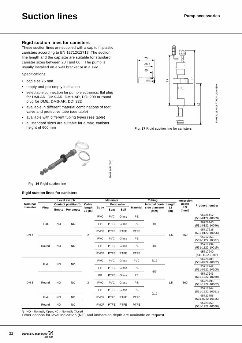
Rigid suction lines for canistersThese suction lines are supplied with a cap to fit plastic canisters according to EN 12712/12713. The suction line length and the cap size are suitable for standard canister sizes between 20 l and 60 l. The pump is usually installed on a wall bracket or in a skid.
Specifications:
• cap size 75 mm• empty and pre-empty indication• selectable connection for pump electronics: flat plug
for DMI-AR, DMX-AR, DMH-AR, DDI 209 or round plug for DME, DMS-AR, DDI 222
• available in different material combinations of foot valve and protective tube (see table)
• available with different tubing types (see table)• all standard sizes are suitable for a max. canister
height of 600 mm
Rigid suction lines for canisters
*) NO = Normally Open, NC = Normally ClosedOther options for level indication (NC) and immersion depth are available on request.
TM04
148
5 05
10
Fig. 16 Rigid suction line
TM03
721
8 45
06 /
TM04
141
6 43
09
Fig. 17 Rigid suction line for canisters
75
60.5
55
Nominal diameter
Level switch Materials Tubing Immersion depth
L3[mm]
Product numberPlug
Contact position *) Cable lengthL2 [m]
BodyFoot valve
MaterialInternal / out-side diameter
[mm]
LengthL1[m]Empty Pre-empty Seat Ball
DN 4
Flat NO NO
2
PVC PVC Glass PE
4/6
1.5 660
96728412(531-0122-10009)
PP PTFE Glass PE 96728440(531-0122-10046)
PVDF PTFE PTFE PTFE 95717238(531-0122-10095)
Round NO NO
PVC PVC Glass PE
4/6
95712065(531-1122-10007)
PP PTFE Glass PE 95717239(531-1122-10015)
PVDF PTFE PTFE PTFE 95717240(531-1122-10016
DN 8
Flat NO NO
2
PVC PVC Glass PVC 6/12
1.5 660
96728708(531-0222-10002)
PP PTFE Glass PE6/9
95717242(531-0222-10105)
Round NO NO
PP PTFE Glass PE 95717243(531-1222-10060)
PVC PVC Glass PE
9/12
96728795(531-1222-10002)
PP PTFE Glass PE 95717244(531-1222-10061)
Flat NO NO PVDF PTFE PTFE PTFE 95723758(531-0222-10115)
Round NO NO PVDF PTFE PTFE PTFE 95723759(531-1222-10070)
Suction lines Pump accessories
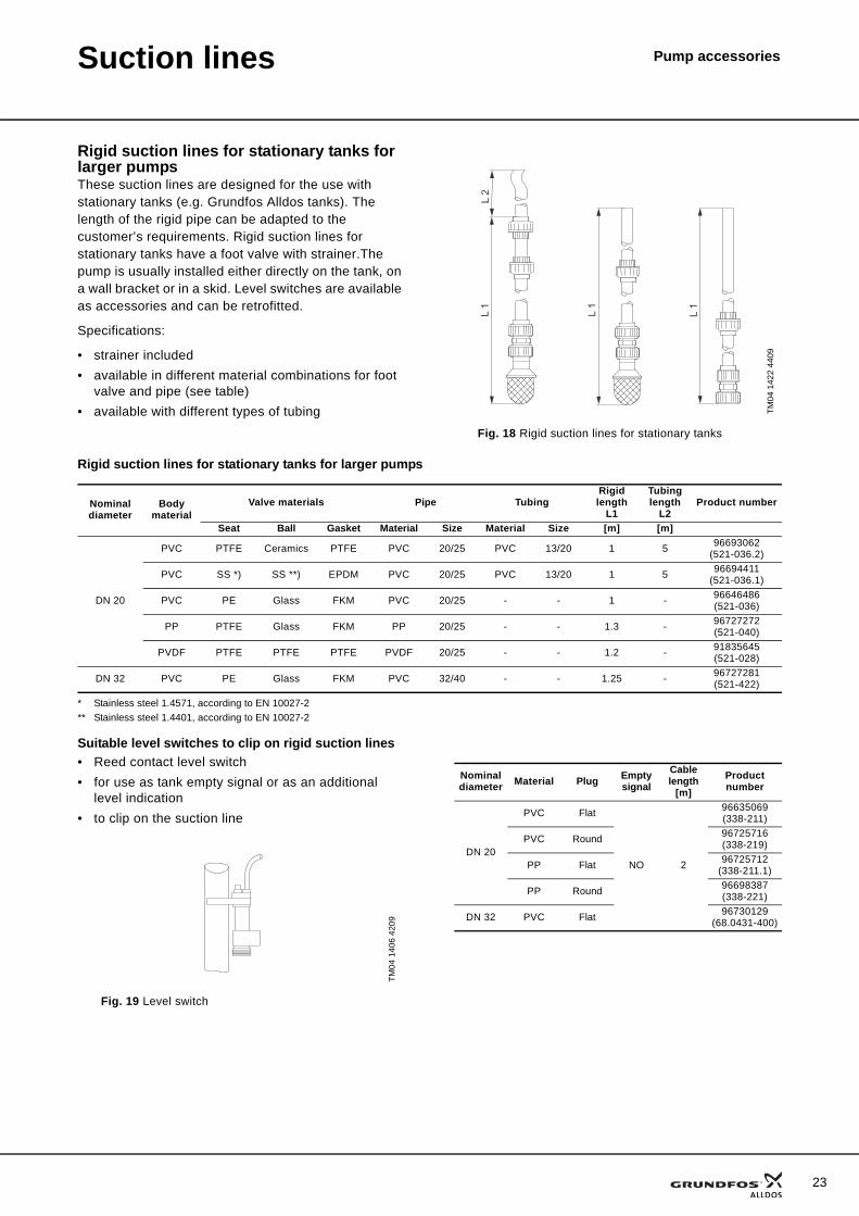
Rigid suction lines for stationary tanks for larger pumpsThese suction lines are designed for the use with stationary tanks (e.g. Grundfos Alldos tanks). The length of the rigid pipe can be adapted to the customer’s requirements. Rigid suction lines for stationary tanks have a foot valve with strainer.The pump is usually installed either directly on the tank, on a wall bracket or in a skid. Level switches are available as accessories and can be retrofitted.
Specifications:
• strainer included• available in different material combinations for foot
valve and pipe (see table)• available with different types of tubing
Rigid suction lines for stationary tanks for larger pumps
* Stainless steel 1.4571, according to EN 10027-2** Stainless steel 1.4401, according to EN 10027-2
Suitable level switches to clip on rigid suction lines• Reed contact level switch• for use as tank empty signal or as an additional
level indication• to clip on the suction line
TM04
142
2 44
09
Fig. 18 Rigid suction lines for stationary tanks
L 1
L 1
L 1
L 2
Nominal diameter
Body material
Valve materials Pipe TubingRigid length
L1
Tubing length
L2Product number
Seat Ball Gasket Material Size Material Size [m] [m]
DN 20
PVC PTFE Ceramics PTFE PVC 20/25 PVC 13/20 1 5 96693062(521-036.2)
PVC SS *) SS **) EPDM PVC 20/25 PVC 13/20 1 5 96694411(521-036.1)
PVC PE Glass FKM PVC 20/25 - - 1 - 96646486(521-036)
PP PTFE Glass FKM PP 20/25 - - 1.3 - 96727272(521-040)
PVDF PTFE PTFE PTFE PVDF 20/25 - - 1.2 - 91835645(521-028)
DN 32 PVC PE Glass FKM PVC 32/40 - - 1.25 - 96727281(521-422)
TM04
140
6 42
09
Fig. 19 Level switch
Nominal diameter Material Plug Empty
signalCable length
[m]Product number
DN 20
PVC Flat
NO 2
96635069(338-211)
PVC Round 96725716(338-219)
PP Flat 96725712(338-211.1)
PP Round 96698387(338-221)
DN 32 PVC Flat 96730129(68.0431-400)
23
24
Suction lines Pump accessories
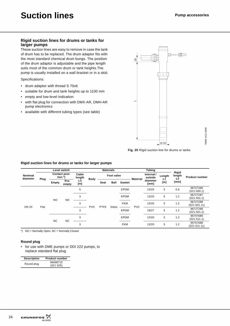
Rigid suction lines for drums or tanks for larger pumpsThese suction lines are easy to remove in case the tank of drum has to be replaced. The drum adaptor fits with the most standard chemical drum bungs. The position of the drum adaptor is adjustable and the pipe length suits most of the common drum or tank heights.The pump is usually installed on a wall bracket or in a skid.
Specifications:
• drum adaptor with thread S 70x6• suitable for drum and tank heights up to 1100 mm• empty and low-level indication• with flat plug for connection with DMX-AR, DMH-AR
pump electronics• available with different tubing types (see table)
Rigid suction lines for drums or tanks for larger pumps
*) NO = Normally Open, NC = Normally Closed
Round plug• for use with DME pumps or DDI 222 pumps, to
replace standard flat plug
TM04
141
1 43
09
Fig. 20 Rigid suction line for drums or tanks
Ø 50
28L
Nominal diameter
Level switch Materials TubingRigid length
L2[mm]
Product numberPlug
Contact posi-tion *)
Cable length
L3[m]
BodyFoot valve
MaterialInternal / outside
diameter[mm]
LengthL1[m]Empty Pre-
empty Seat Ball Gasket
DN 20 Flat
NO NO
5
PVC PTFE Glass
EPDM
PVC
13/20 5 0.6 96727286(521-500.1)
3 EPDM 13/20 5 1.2 96727287(521-501.1)
3 FKM 13/20 5 1.2 96727288(521-501.11)
3 EPDM 19/27 5 1.2 96727289(521-501.2)
NC NC3 EPDM 13/20 5 1.2 95707689
(521-511.1)
3 FKM 13/20 5 1.2 95707688(521-511.11)
Description Product number
Round plug 96698715(321-325)
Suction lines Pump accessories
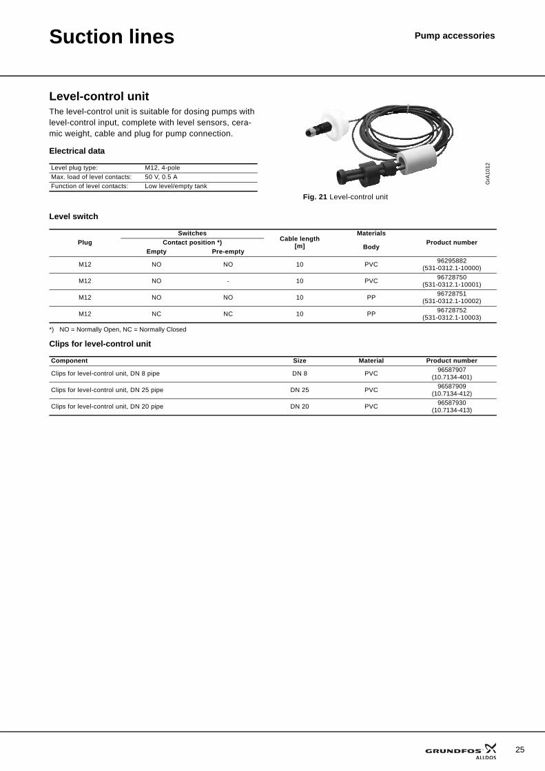
Level-control unitThe level-control unit is suitable for dosing pumps with level-control input, complete with level sensors, cera-mic weight, cable and plug for pump connection.
Electrical data
Level switch
*) NO = Normally Open, NC = Normally Closed
Clips for level-control unit
Level plug type: M12, 4-poleMax. load of level contacts: 50 V, 0.5 AFunction of level contacts: Low level/empty tank G
rA10
12
Fig. 21 Level-control unit
PlugSwitches
Cable length[m]
MaterialsProduct numberContact position *)
BodyEmpty Pre-empty
M12 NO NO 10 PVC 96295882(531-0312.1-10000)
M12 NO - 10 PVC 96728750(531-0312.1-10001)
M12 NO NO 10 PP 96728751(531-0312.1-10002)
M12 NC NC 10 PP 96728752(531-0312.1-10003)
Component Size Material Product number
Clips for level-control unit, DN 8 pipe DN 8 PVC 96587907(10.7134-401)
Clips for level-control unit, DN 25 pipe DN 25 PVC 96587909(10.7134-412)
Clips for level-control unit, DN 20 pipe DN 20 PVC 96587930(10.7134-413)
25
26
Pump accessoriesInjection valves
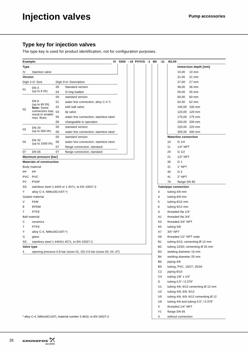
Type key for injection valvesThe type key is used for product identification, not for configuration purposes.
Example: IV 0200 - 16 PV/V/G -1 B6 -11 /62,00
Type Immersion depth [mm]
IV Injection valve 10,00 10 mm
Version 21,00 21 mm
Digit 1+2: Size Digit 3+4: Description 27,00 27 mm
01 DN 4 (up to 6 l/h)
00 Standard version 36,00 36 mm
04 O-ring loaded 55,00 55 mm
02
DN 8(up to 60 l/h)Note: Some connectors may result in smaller max. flows.
00 standard version 60,00 60 mm
01 water line connection, alloy C-4 *) 62,00 62 mm
02 with ball valve 100,00 100 mm
03 lip valve 120,00 120 mm
05 water line connection, stainless steel 175,00 175 mm
06 changeable in operation 200,00 200 mm
03 DN 20 (up to 500 l/h)
00 standard version 220,00 220 mm
06 water line connection, stainless steel 300,00 300 mm
04 DN 32(up to 1500 l/h)
00 standard version Waterline connection06 water line connection, stainless steel 10 G 1/4
07 flange connection, standard 11 1/4” NPT
07 DN 65 07 flange connection, standard 20 G 1/2
Maximum pressure [bar] 21 1/2” NPT
Materials of construction 30 G 1
Body material 31 1” NPT
PP PP 40 G 2
PVC PVC 41 2” NPT
PV PVDF 70 flange DN 80
SS stainless steel 1.4404 or 1.4571, to EN 10027-2 Tube/pipe connectionY alloy C-4, NiMo16Cr16Ti *) 3 tubing 4/6 mm
Gasket material 4 tubing 6/9 mm
V FKM 5 tubing 6/12 mm
E EPDM 6 tubing 9/12 mm
T PTFE A threaded Rp 1/4”
Ball material A1 threaded Rp 3/4”
C ceramics A3 threaded 3/4” NPT
T PTFE A5 tubing 5/8
Y alloy C-4, NiMo16Cr16Ti *) A7 3/4” NPT
G glass A9 threaded 1/2” NPT male
SS stainless steel 1.4404/1.4571, to EN 10027-2 B1 tubing 6/12; cementing Ø 12 mm
Valve type B2 tubing 13/20; cementing Ø 25 mm
4 opening pressure 0.8 bar (sizes 01, 02) 0.6 bar (sizes 03, 04, 07) B3 welding diameter 16 mm
B4 welding diameter 25 mm
B6 piping 4/6
B9 tubing, PVC, 19/27; 25/34
C2 piping 8/10
C4 tubing 1/8” x 1/4”
S tubing 0.5” / 0.375”
U1 tubing 4/6; 6/12 cementing Ø 12 mm
U2 tubing 4/6; 6/9; 9/12
U5 tubing 4/6; 6/9; 6/12 cementing Ø 12
U6 tubing 4/6 and tubing 0.5” / 0.375”
V threaded 1/4” NPT
Y1 flange DN 65
* alloy C-4, NiMo16Cr16Ti, material number 2.4610, to EN 10027-2 X without connection
Injection valves Pump accessories
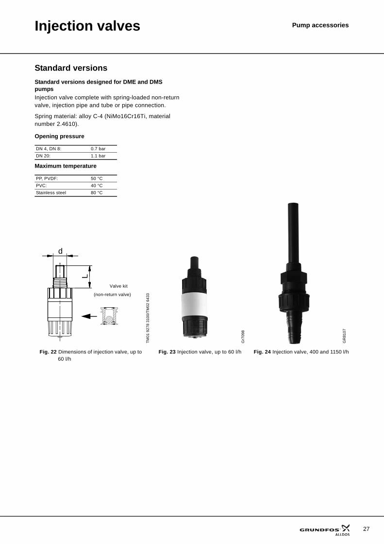
Standard versionsStandard versions designed for DME and DMS pumpsInjection valve complete with spring-loaded non-return valve, injection pipe and tube or pipe connection.
Spring material: alloy C-4 (NiMo16Cr16Ti, material number 2.4610).
Opening pressure
Maximum temperature
DN 4, DN 8: 0.7 barDN 20: 1.1 bar
PP, PVDF: 50 °CPVC: 40 °CStainless steel 80 °C
TM01
927
8 31
00/T
M02
643
3
Gr7
098
GR
8107
Fig. 22 Dimensions of injection valve, up to 60 l/h
Fig. 23 Injection valve, up to 60 l/h Fig. 24 Injection valve, 400 and 1150 l/h
L
d
(non-return valve)
Valve kit
27
28
Injection valves Pump accessories
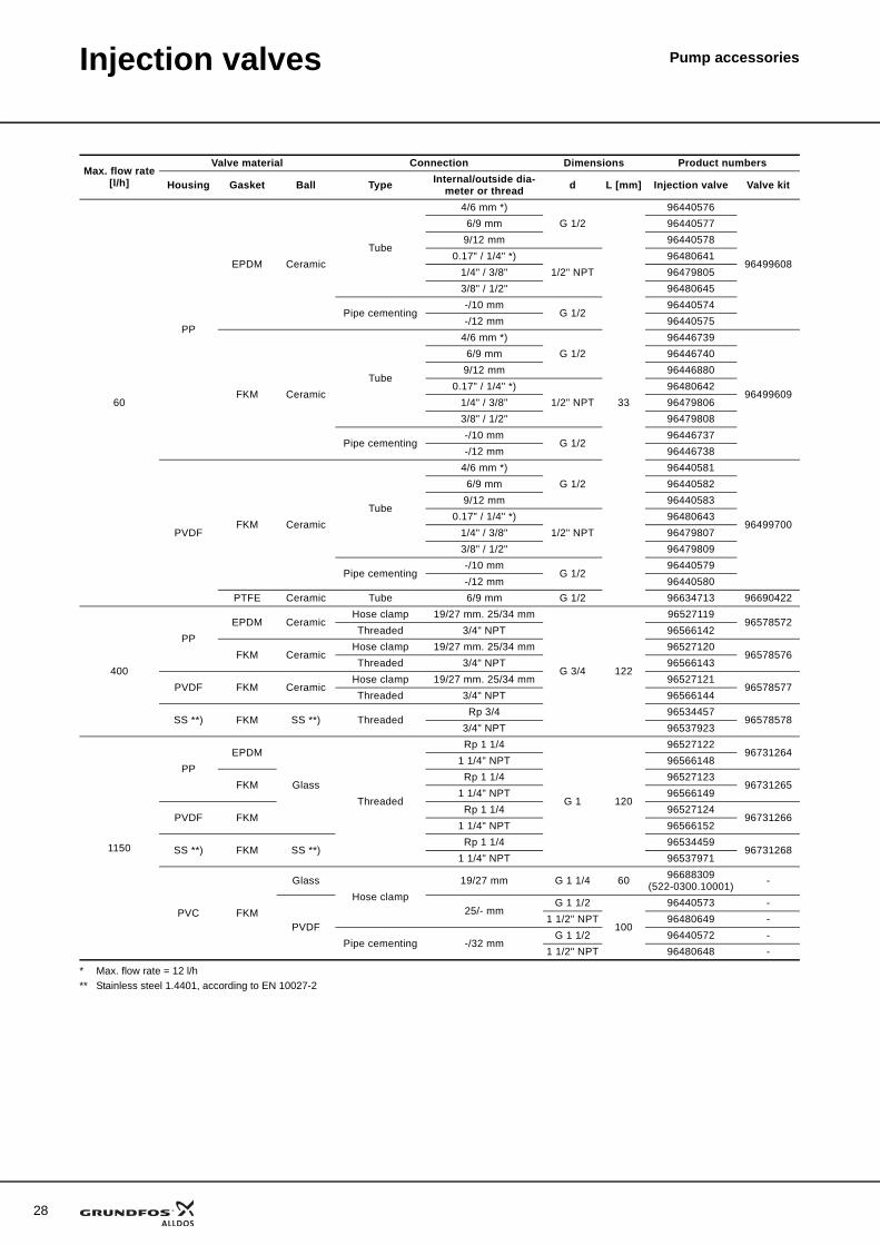
* Max. flow rate = 12 l/h** Stainless steel 1.4401, according to EN 10027-2
Max. flow rate[l/h]
Valve material Connection Dimensions Product numbers
Housing Gasket Ball Type Internal/outside dia-meter or thread d L [mm] Injection valve Valve kit
60
PP
EPDM CeramicTube
4/6 mm *)G 1/2
33
96440576
96499608
6/9 mm 964405779/12 mm 96440578
0.17" / 1/4" *)1/2" NPT
964806411/4" / 3/8" 964798053/8" / 1/2" 96480645
Pipe cementing-/10 mm
G 1/296440574
-/12 mm 96440575
FKM CeramicTube
4/6 mm *)G 1/2
96446739
96499609
6/9 mm 964467409/12 mm 96446880
0.17" / 1/4" *)1/2" NPT
964806421/4" / 3/8" 964798063/8" / 1/2" 96479808
Pipe cementing-/10 mm
G 1/296446737
-/12 mm 96446738
PVDFFKM Ceramic
Tube
4/6 mm *)G 1/2
96440581
96499700
6/9 mm 964405829/12 mm 96440583
0.17" / 1/4" *)1/2" NPT
964806431/4" / 3/8" 964798073/8" / 1/2" 96479809
Pipe cementing-/10 mm
G 1/296440579
-/12 mm 96440580PTFE Ceramic Tube 6/9 mm G 1/2 96634713 96690422
400
PPEPDM Ceramic
Hose clamp 19/27 mm. 25/34 mm
G 3/4 122
9652711996578572
Threaded 3/4" NPT 96566142
FKM CeramicHose clamp 19/27 mm. 25/34 mm 96527120
96578576Threaded 3/4" NPT 96566143
PVDF FKM CeramicHose clamp 19/27 mm. 25/34 mm 96527121
96578577Threaded 3/4" NPT 96566144
SS **) FKM SS **) ThreadedRp 3/4 96534457
965785783/4" NPT 96537923
1150
PPEPDM
GlassThreaded
Rp 1 1/4
G 1 120
9652712296731264
1 1/4" NPT 96566148
FKMRp 1 1/4 96527123
967312651 1/4" NPT 96566149
PVDF FKMRp 1 1/4 96527124
967312661 1/4" NPT 96566152
SS **) FKM SS **)Rp 1 1/4 96534459
967312681 1/4" NPT 96537971
PVC FKM
GlassHose clamp
19/27 mm G 1 1/4 60 96688309(522-0300.10001) -
PVDF25/- mm
G 1 1/2
100
96440573 -1 1/2" NPT 96480649 -
Pipe cementing -/32 mmG 1 1/2 96440572 -
1 1/2" NPT 96480648 -
Injection valves Pump accessories
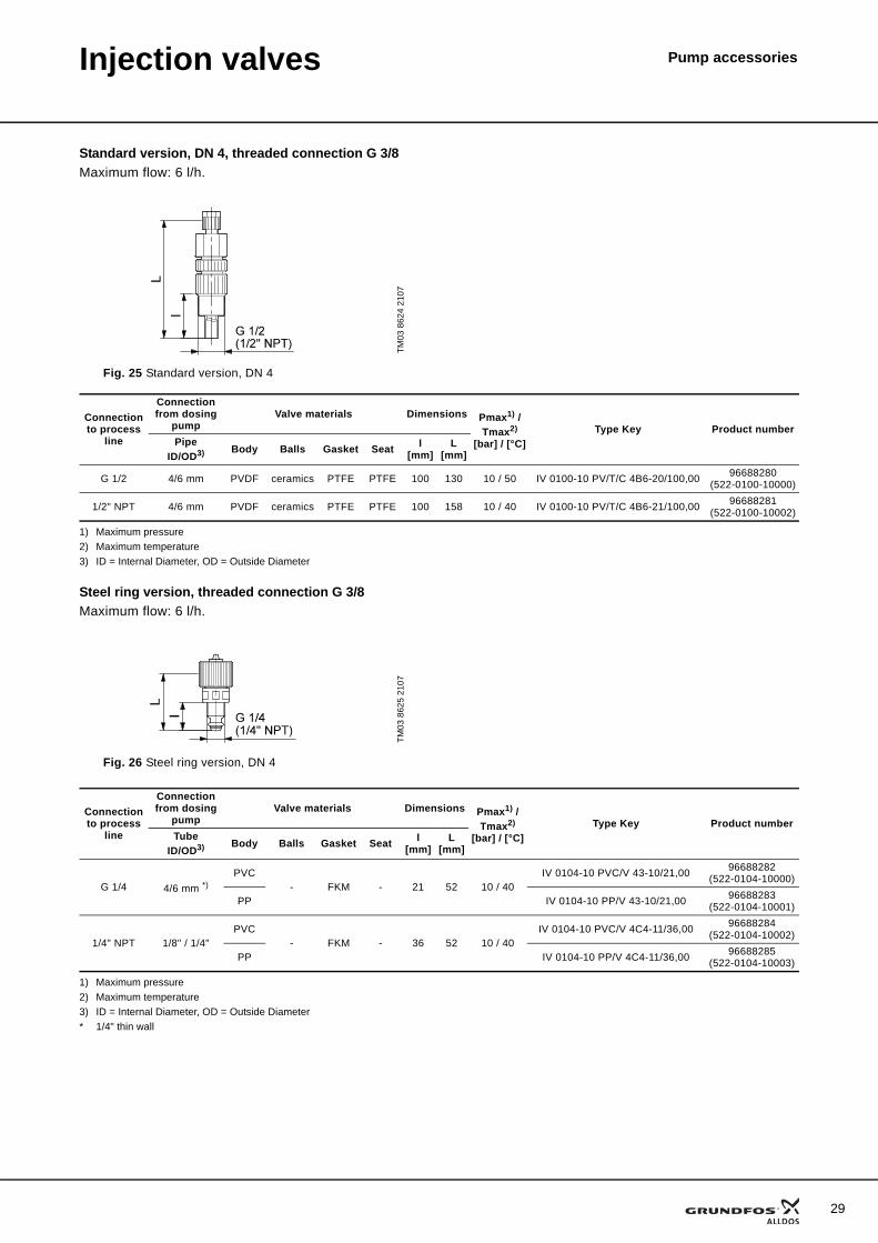
Standard version, DN 4, threaded connection G 3/8Maximum flow: 6 l/h.
1) Maximum pressure2) Maximum temperature3) ID = Internal Diameter, OD = Outside Diameter
Steel ring version, threaded connection G 3/8Maximum flow: 6 l/h.
1) Maximum pressure2) Maximum temperature3) ID = Internal Diameter, OD = Outside Diameter* 1/4" thin wall
TM03
862
4 21
07
Fig. 25 Standard version, DN 4
Connection to process
line
Connection from dosing
pumpValve materials Dimensions Pmax1) /
Tmax2)
[bar] / [°C]Type Key Product number
PipeID/OD3) Body Balls Gasket Seat l
[mm]L
[mm]
G 1/2 4/6 mm PVDF ceramics PTFE PTFE 100 130 10 / 50 IV 0100-10 PV/T/C 4B6-20/100,00 96688280(522-0100-10000)
1/2" NPT 4/6 mm PVDF ceramics PTFE PTFE 100 158 10 / 40 IV 0100-10 PV/T/C 4B6-21/100,00 96688281(522-0100-10002)
TM03
862
5 21
07
Fig. 26 Steel ring version, DN 4
Connection to process
line
Connection from dosing
pumpValve materials Dimensions Pmax1) /
Tmax2)
[bar] / [°C]Type Key Product number
TubeID/OD3) Body Balls Gasket Seat l
[mm]L
[mm]
G 1/4 4/6 mm *)PVC
- FKM - 21 52 10 / 40IV 0104-10 PVC/V 43-10/21,00 96688282
(522-0104-10000)
PP IV 0104-10 PP/V 43-10/21,00 96688283(522-0104-10001)
1/4" NPT 1/8" / 1/4"PVC
- FKM - 36 52 10 / 40IV 0104-10 PVC/V 4C4-11/36,00 96688284
(522-0104-10002)
PP IV 0104-10 PP/V 4C4-11/36,00 96688285(522-0104-10003)
29
30
Injection valves Pump accessories
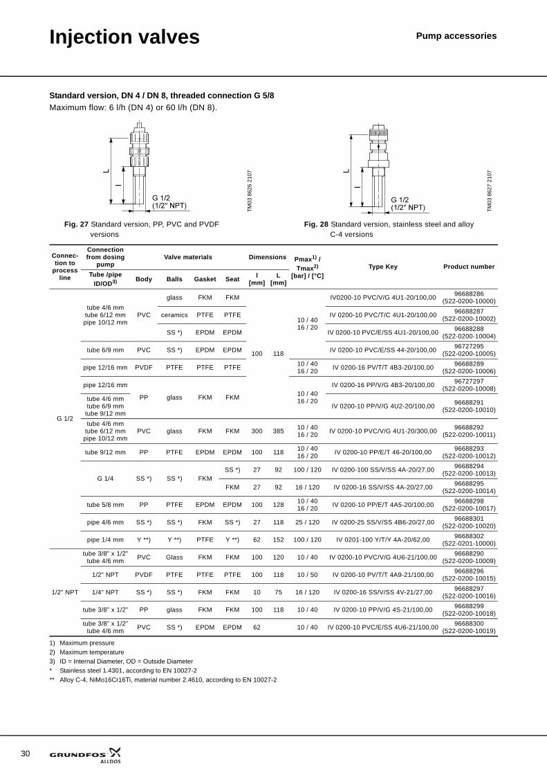
Standard version, DN 4 / DN 8, threaded connection G 5/8Maximum flow: 6 l/h (DN 4) or 60 l/h (DN 8).
1) Maximum pressure2) Maximum temperature3) ID = Internal Diameter, OD = Outside Diameter* Stainless steel 1.4301, according to EN 10027-2** Alloy C-4, NiMo16Cr16Ti, material number 2.4610, according to EN 10027-2
TM03
862
6 21
07
TM03
862
7 21
07
Fig. 27 Standard version, PP, PVC and PVDF versions
Fig. 28 Standard version, stainless steel and alloy C-4 versions
Connec-tion to
process line
Connection from dosing
pumpValve materials Dimensions Pmax1) /
Tmax2)
[bar] / [°C]Type Key Product number
Tube /pipeID/OD3) Body Balls Gasket Seat l
[mm]L
[mm]
G 1/2
tube 4/6 mmtube 6/12 mmpipe 10/12 mm
PVC
glass FKM FKM
100 118
10 / 4016 / 20
IV0200-10 PVC/V/G 4U1-20/100,00 96688286(522-0200-10000)
ceramics PTFE PTFE IV 0200-10 PVC/T/C 4U1-20/100,00 96688287(522-0200-10002)
SS *) EPDM EPDM IV 0200-10 PVC/E/SS 4U1-20/100,00 96688288(522-0200-10004)
tube 6/9 mm PVC SS *) EPDM EPDM IV 0200-10 PVC/E/SS 44-20/100,00 96727295(522-0200-10005)
pipe 12/16 mm PVDF PTFE PTFE PTFE 10 / 4016 / 20 IV 0200-16 PV/T/T 4B3-20/100,00 96688289
(522-0200-10006)
pipe 12/16 mm
PP glass FKM FKM 10 / 4016 / 20
IV 0200-16 PP/V/G 4B3-20/100,00 96727297(522-0200-10008)
tube 4/6 mmtube 6/9 mm
tube 9/12 mmIV 0200-10 PP/V/G 4U2-20/100,00 96688291
(522-0200-10010)
tube 4/6 mmtube 6/12 mmpipe 10/12 mm
PVC glass FKM FKM 300 385 10 / 4016 / 20 IV 0200-10 PVC/V/G 4U1-20/300,00 96688292
(522-0200-10011)
tube 9/12 mm PP PTFE EPDM EPDM 100 118 10 / 4016 / 20 IV 0200-10 PP/E/T 46-20/100,00 96688293
(522-0200-10012)
G 1/4 SS *) SS *) FKMSS *) 27 92 100 / 120 IV 0200-100 SS/V/SS 4A-20/27,00 96688294
(522-0200-10013)
FKM 27 92 16 / 120 IV 0200-16 SS/V/SS 4A-20/27,00 96688295(522-0200-10014)
tube 5/8 mm PP PTFE EPDM EPDM 100 128 10 / 4016 / 20 IV 0200-10 PP/E/T 4A5-20/100,00 96688298
(522-0200-10017)
pipe 4/6 mm SS *) SS *) FKM SS *) 27 118 25 / 120 IV 0200-25 SS/V/SS 4B6-20/27,00 96688301(522-0200-10020)
pipe 1/4 mm Y **) Y **) PTFE Y **) 62 152 100 / 120 IV 0201-100 Y/T/Y 4A-20/62,00 96688302(522-0201-10000)
1/2" NPT
tube 3/8” x 1/2”tube 4/6 mm PVC Glass FKM FKM 100 120 10 / 40 IV 0200-10 PVC/V/G 4U6-21/100,00 96688290
(522-0200-10009)
1/2" NPT PVDF PTFE PTFE PTFE 100 118 10 / 50 IV 0200-10 PV/T/T 4A9-21/100,00 96688296(522-0200-10015)
1/4" NPT SS *) SS *) FKM FKM 10 75 16 / 120 IV 0200-16 SS/V/SS 4V-21/27,00 96688297(522-0200-10016)
tube 3/8” x 1/2” PP glass FKM FKM 100 118 10 / 40 IV 0200-10 PP/V/G 4S-21/100,00 96688299(522-0200-10018)
tube 3/8” x 1/2”tube 4/6 mm PVC SS *) EPDM EPDM 62 10 / 40 IV 0200-10 PVC/E/SS 4U6-21/100,00 96688300
(522-0200-10019)
Injection valves Pump accessories
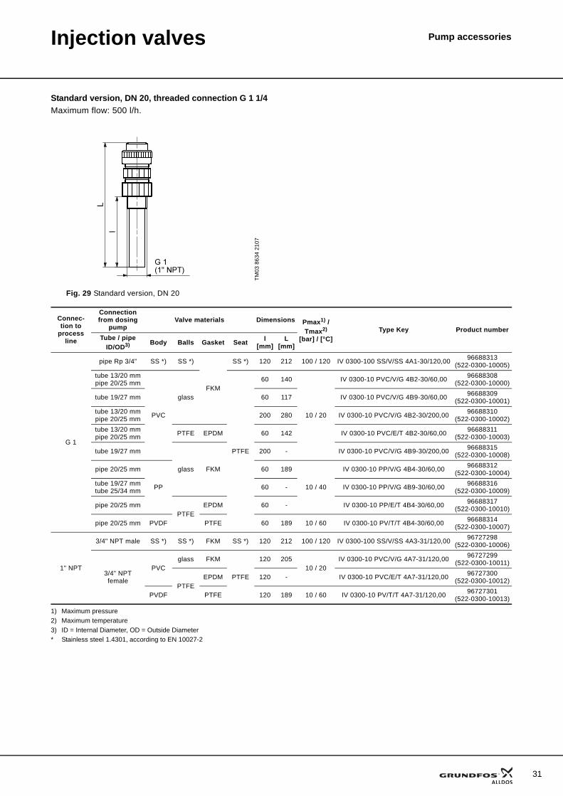
Standard version, DN 20, threaded connection G 1 1/4Maximum flow: 500 l/h.
1) Maximum pressure2) Maximum temperature3) ID = Internal Diameter, OD = Outside Diameter* Stainless steel 1.4301, according to EN 10027-2
TM03
863
4 21
07
Fig. 29 Standard version, DN 20
Connec-tion to
process line
Connection from dosing
pumpValve materials Dimensions Pmax1) /
Tmax2)
[bar] / [°C]Type Key Product number
Tube / pipeID/OD3) Body Balls Gasket Seat l
[mm]L
[mm]
G 1
pipe Rp 3/4” SS *) SS *)
FKM
SS *) 120 212 100 / 120 IV 0300-100 SS/V/SS 4A1-30/120,00 96688313(522-0300-10005)
tube 13/20 mmpipe 20/25 mm
PVC
glass
PTFE
60 140
10 / 20
IV 0300-10 PVC/V/G 4B2-30/60,00 96688308(522-0300-10000)
tube 19/27 mm 60 117 IV 0300-10 PVC/V/G 4B9-30/60,00 96688309(522-0300-10001)
tube 13/20 mmpipe 20/25 mm 200 280 IV 0300-10 PVC/V/G 4B2-30/200,00 96688310
(522-0300-10002)tube 13/20 mmpipe 20/25 mm PTFE EPDM 60 142 IV 0300-10 PVC/E/T 4B2-30/60,00 96688311
(522-0300-10003)
tube 19/27 mm
glass FKM
200 - IV 0300-10 PVC/V/G 4B9-30/200,00 96688315(522-0300-10008)
pipe 20/25 mm
PP
60 189
10 / 40
IV 0300-10 PP/V/G 4B4-30/60,00 96688312(522-0300-10004)
tube 19/27 mmtube 25/34 mm 60 - IV 0300-10 PP/V/G 4B9-30/60,00 96688316
(522-0300-10009)
pipe 20/25 mmPTFE
EPDM 60 - IV 0300-10 PP/E/T 4B4-30/60,00 96688317(522-0300-10010)
pipe 20/25 mm PVDF PTFE 60 189 10 / 60 IV 0300-10 PV/T/T 4B4-30/60,00 96688314(522-0300-10007)
1" NPT
3/4" NPT male SS *) SS *) FKM SS *) 120 212 100 / 120 IV 0300-100 SS/V/SS 4A3-31/120,00 96727298(522-0300-10006)
3/4" NPT female
PVCglass FKM
PTFE
120 20510 / 20
IV 0300-10 PVC/V/G 4A7-31/120,00 96727299(522-0300-10011)
PTFEEPDM 120 - IV 0300-10 PVC/E/T 4A7-31/120,00 96727300
(522-0300-10012)
PVDF PTFE 120 189 10 / 60 IV 0300-10 PV/T/T 4A7-31/120,00 96727301(522-0300-10013)
31
32
Injection valves Pump accessories
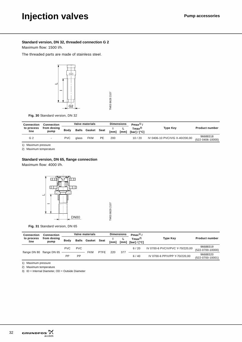
Standard version, DN 32, threaded connection G 2Maximum flow: 1500 l/h.
The threaded parts are made of stainless steel.
1) Maximum pressure2) Maximum temperature
Standard version, DN 65, flange connectionMaximum flow: 4000 l/h.
1) Maximum pressure2) Maximum temperature3) ID = Internal Diameter, OD = Outside Diameter
TM03
862
8 21
07
Fig. 30 Standard version, DN 32
Connection to process
line
Connection from dosing
pump
Valve materials Dimensions Pmax1) / Tmax2)
[bar] / [°C]Type Key Product number
Body Balls Gasket Seat l[mm]
L[mm]
G 2 - PVC glass FKM PE 200 10 / 20 IV 0406-10 PVC/V/G X-40/200,00 96688318(522-0406-10000)
TM03
862
9 21
07
Fig. 31 Standard version, DN 65
Connection to process
line
Connection from dosing
pump
Valve materials Dimensions Pmax1) / Tmax2)
[bar] / [°C]Type Key Product number
Body Balls Gasket Seat l[mm]
L[mm]
flange DN 80 flange DN 65PVC PVC
FKM PTFE 220 3776 / 20 IV 0700-6 PVC/V/PVC Y-70/220,00 96688319
(522-0700-10000)
PP PP 6 / 40 IV 0700-6 PP/V/PP Y-70/220,00 96688320(522-0700-10001)
Injection valves Pump accessories
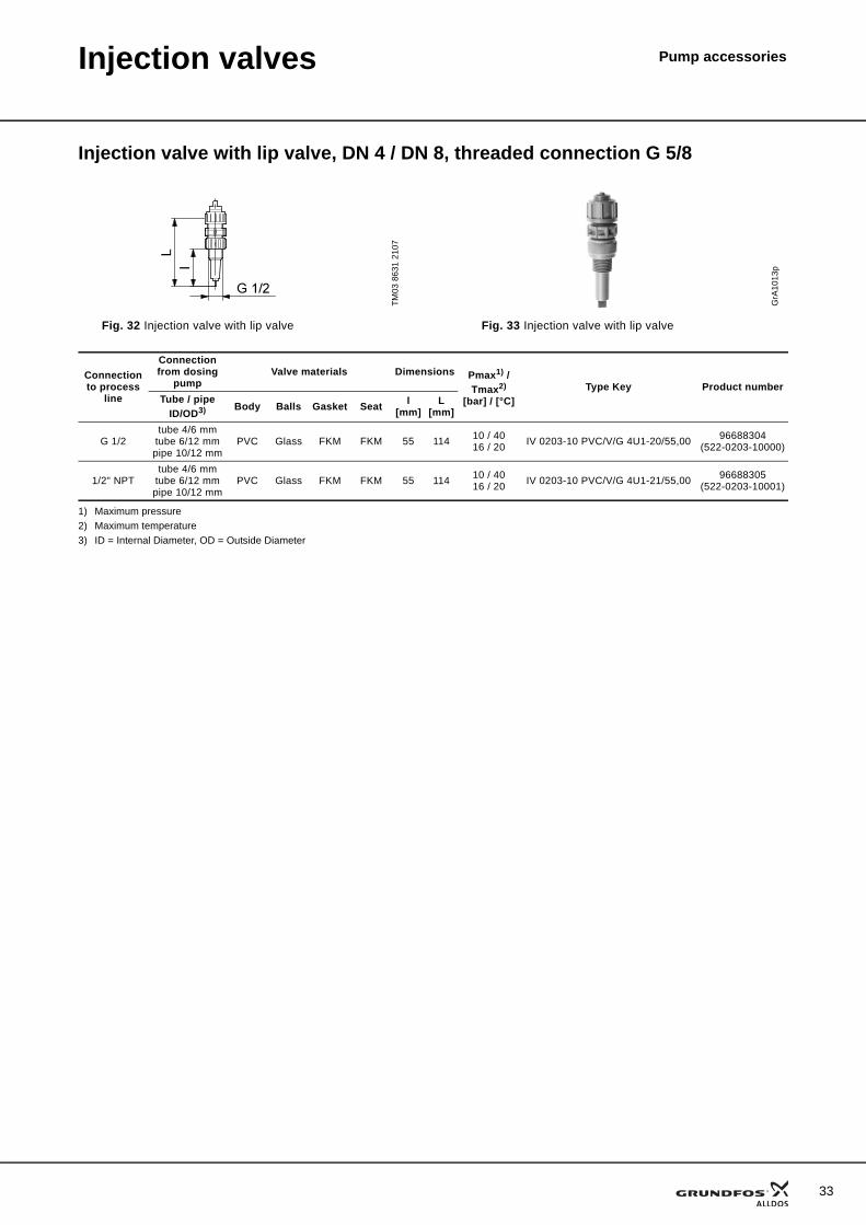
Injection valve with lip valve, DN 4 / DN 8, threaded connection G 5/8
1) Maximum pressure2) Maximum temperature3) ID = Internal Diameter, OD = Outside Diameter
TM03
863
1 21
07
Fig. 32 Injection valve with lip valve
GrA
1013
p
Fig. 33 Injection valve with lip valve
Connection to process
line
Connection from dosing
pumpValve materials Dimensions Pmax1) /
Tmax2)
[bar] / [°C]Type Key Product number
Tube / pipeID/OD3) Body Balls Gasket Seat l
[mm]L
[mm]
G 1/2tube 4/6 mm
tube 6/12 mmpipe 10/12 mm
PVC Glass FKM FKM 55 114 10 / 4016 / 20 IV 0203-10 PVC/V/G 4U1-20/55,00 96688304
(522-0203-10000)
1/2" NPTtube 4/6 mm
tube 6/12 mmpipe 10/12 mm
PVC Glass FKM FKM 55 114 10 / 4016 / 20 IV 0203-10 PVC/V/G 4U1-21/55,00 96688305
(522-0203-10001)
33

34
Injection valves Pump accessories
Hot-injection valve, M 30The hot-injection valve kit is complete with isolating valve, pipe and tube connection fitting for chemical injection into steam and hot-water applications.
The hot-injection valve allows for direct dosing injection into systems with a temperature of maximum 150 °C at the injection point.
The hot-injection valve kit is delivered non-assembled to facilitate adaptation to the actual application.
Materials and dimensions
Hot-injection valve, DN 4 / DN 8
1) Maximum pressure2) Maximum temperature* Stainless steel 1.4571, according to EN 10027-2** Stainless steel 1.4401, according to EN 10027-2
Cooling pipe
* Stainless steel 1.4571, according to EN 10027-2
Component Material DimensionIsolating ball valve Stainless steel, DIN 1.4401 1/2"Pipe, length 1 m Stainless steel, DIN 1.4401 8/10 mmPipe connection Stainless steel, DIN 1.4401 1/2"Tube connection PVDF 6/9 mm
GR
750
6_p
Fig. 34 Hot-injection valve
Max. flow rate[l/h] Size
Materials ConnectionProduct number
Connection Gasket Valve ball Type Tube diameter50 DN 4 PVDF FKM Ceramic Tube 6/9 mm 96534472
TM03
863
2 21
07
Fig. 35 Hot-injection valves, DN 4 / DN 8
Connection to process line
Connection from dosing pump Valve materials DimensionsPmax1) / Tmax2)
[bar] / [°C]Product number
Pipe Thread Body Balls Gasket Seat l[mm]
L[mm]
G 1/2 Rp 1/4” G 5/8 SS *) SS **) FKM SS *) 27 118 16 / 120 96688295(522-0200-10014)
Connection SizeMaterial Max. operating pressure
[bar]Length[mm] Product number
Pipe Gasket
5/8” DN 8 SS *) FKM 100420 96727309
(522-095)
1000 96727310(522-096)
Injection valves Pump accessories
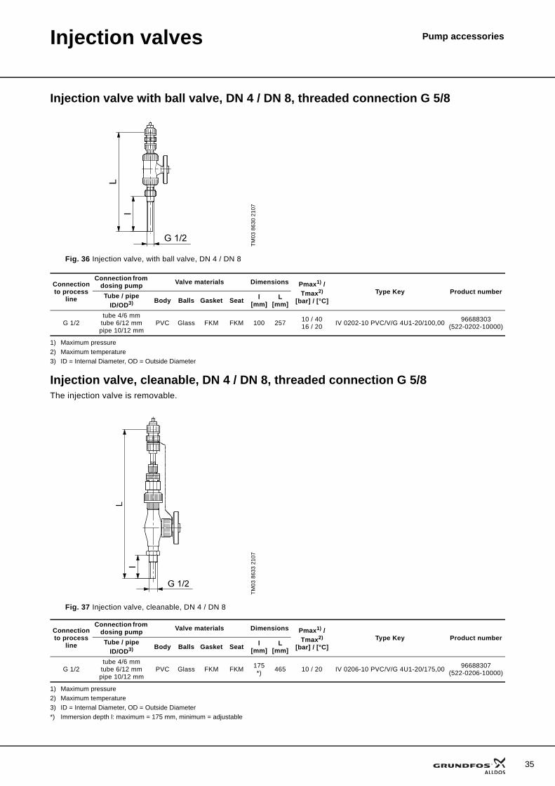
Injection valve with ball valve, DN 4 / DN 8, threaded connection G 5/8
1) Maximum pressure2) Maximum temperature3) ID = Internal Diameter, OD = Outside Diameter
Injection valve, cleanable, DN 4 / DN 8, threaded connection G 5/8The injection valve is removable.
1) Maximum pressure2) Maximum temperature3) ID = Internal Diameter, OD = Outside Diameter*) Immersion depth l: maximum = 175 mm, minimum = adjustable
TM03
863
0 21
07Fig. 36 Injection valve, with ball valve, DN 4 / DN 8
Connection to process
line
Connection from dosing pump Valve materials Dimensions Pmax1) /
Tmax2)
[bar] / [°C]Type Key Product numberTube / pipe
ID/OD3) Body Balls Gasket Seat l[mm]
L[mm]
G 1/2tube 4/6 mm
tube 6/12 mmpipe 10/12 mm
PVC Glass FKM FKM 100 257 10 / 4016 / 20 IV 0202-10 PVC/V/G 4U1-20/100,00 96688303
(522-0202-10000)
TM03
863
3 21
07
Fig. 37 Injection valve, cleanable, DN 4 / DN 8
Connection to process
line
Connection from dosing pump Valve materials Dimensions Pmax1) /
Tmax2)
[bar] / [°C]Type Key Product numberTube / pipe
ID/OD3) Body Balls Gasket Seat l[mm]
L[mm]
G 1/2tube 4/6 mm
tube 6/12 mmpipe 10/12 mm
PVC Glass FKM FKM 175 *) 465 10 / 20 IV 0206-10 PVC/V/G 4U1-20/175,00 96688307
(522-0206-10000)
35
36
Pump accessoriesPressure-relief valves
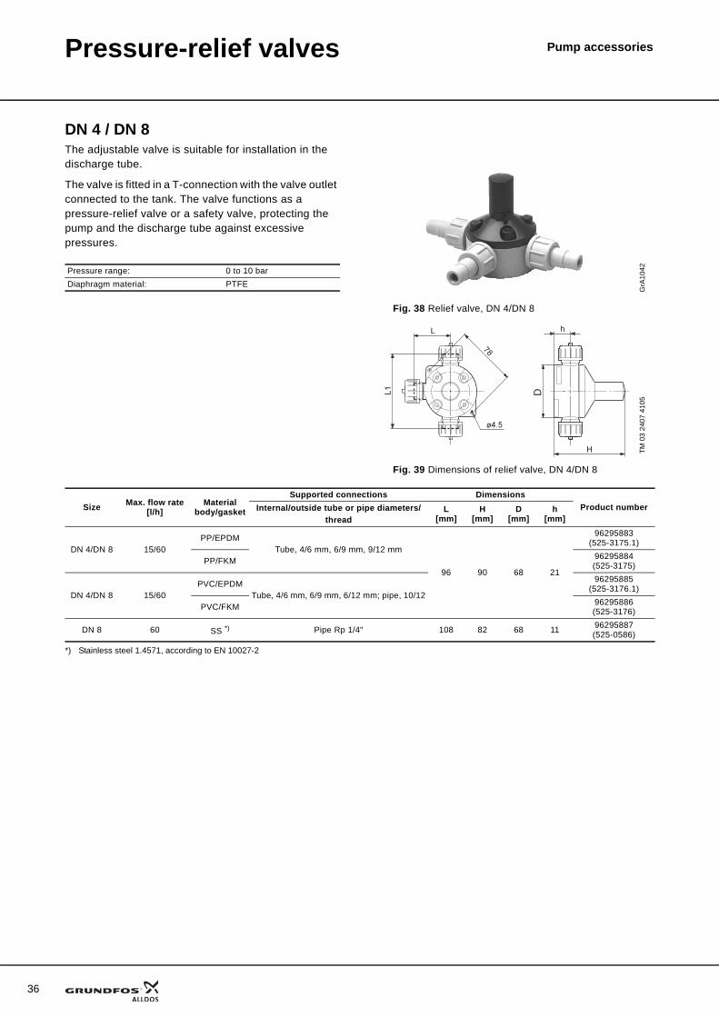
DN 4 / DN 8The adjustable valve is suitable for installation in the discharge tube.
The valve is fitted in a T-connection with the valve outlet connected to the tank. The valve functions as a pressure-relief valve or a safety valve, protecting the pump and the discharge tube against excessive pressures.
*) Stainless steel 1.4571, according to EN 10027-2
Pressure range: 0 to 10 barDiaphragm material: PTFE
GrA
1042
Fig. 38 Relief valve, DN 4/DN 8
TM 0
3 24
07 4
105
Fig. 39 Dimensions of relief valve, DN 4/DN 8
Size Max. flow rate[l/h]
Materialbody/gasket
Supported connections DimensionsProduct numberInternal/outside tube or pipe diameters/
threadL
[mm]H
[mm]D
[mm]h
[mm]
DN 4/DN 8 15/60PP/EPDM
Tube, 4/6 mm, 6/9 mm, 9/12 mm
96 90 68 21
96295883(525-3175.1)
PP/FKM 96295884(525-3175)
DN 4/DN 8 15/60PVC/EPDM
Tube, 4/6 mm, 6/9 mm, 6/12 mm; pipe, 10/12
96295885(525-3176.1)
PVC/FKM 96295886(525-3176)
DN 8 60 SS *) Pipe Rp 1/4" 108 82 68 11 96295887(525-0586)
Pressure-relief valves Pump accessories
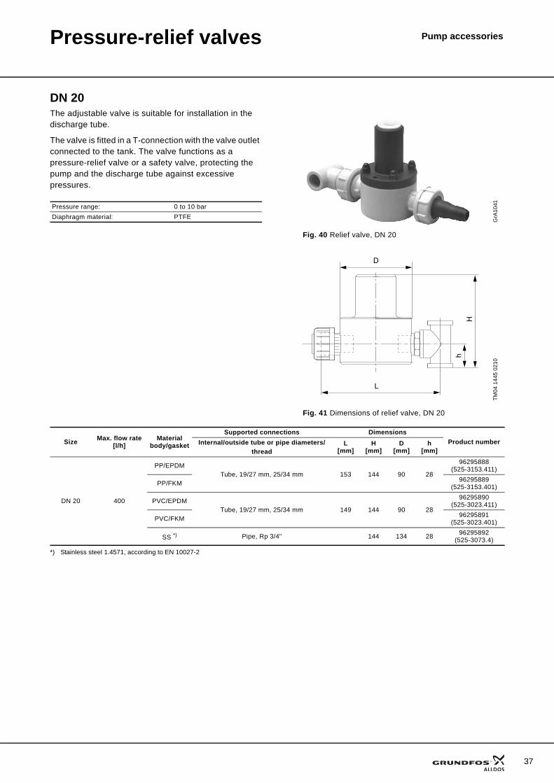
DN 20The adjustable valve is suitable for installation in the discharge tube.
The valve is fitted in a T-connection with the valve outlet connected to the tank. The valve functions as a pressure-relief valve or a safety valve, protecting the pump and the discharge tube against excessive pressures.
*) Stainless steel 1.4571, according to EN 10027-2
Pressure range: 0 to 10 barDiaphragm material: PTFE G
rA10
41
Fig. 40 Relief valve, DN 20
TM04
144
5 02
10
Fig. 41 Dimensions of relief valve, DN 20
D
L
Hh
Size Max. flow rate[l/h]
Materialbody/gasket
Supported connections DimensionsProduct numberInternal/outside tube or pipe diameters/
threadL
[mm]H
[mm]D
[mm]h
[mm]
DN 20 400
PP/EPDMTube, 19/27 mm, 25/34 mm 153 144 90 28
96295888(525-3153.411)
PP/FKM 96295889(525-3153.401)
PVC/EPDMTube, 19/27 mm, 25/34 mm 149 144 90 28
96295890(525-3023.411)
PVC/FKM 96295891(525-3023.401)
SS *) Pipe, Rp 3/4" 144 134 28 96295892(525-3073.4)
37
38
Pressure-relief valves Pump accessories
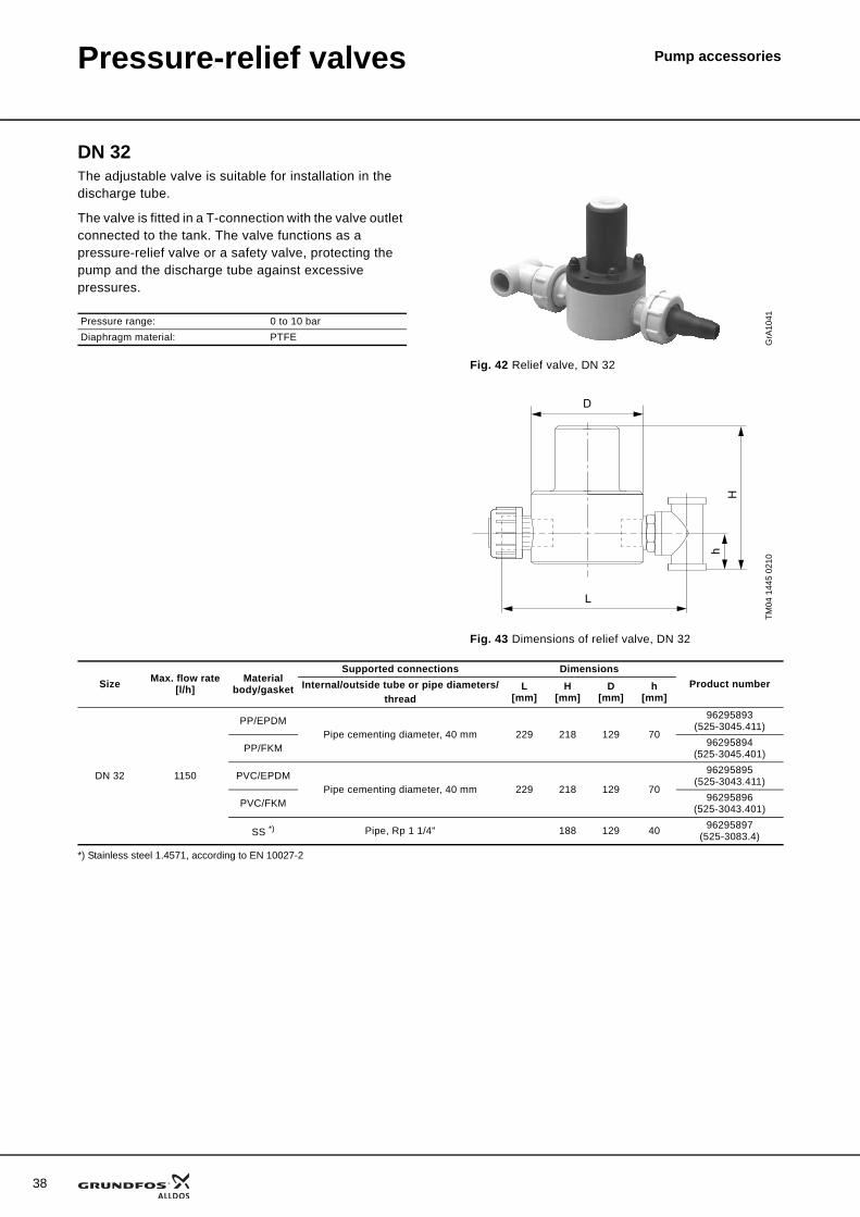
DN 32The adjustable valve is suitable for installation in the discharge tube.
The valve is fitted in a T-connection with the valve outlet connected to the tank. The valve functions as a pressure-relief valve or a safety valve, protecting the pump and the discharge tube against excessive pressures.
*) Stainless steel 1.4571, according to EN 10027-2
Pressure range: 0 to 10 barDiaphragm material: PTFE G
rA10
41
Fig. 42 Relief valve, DN 32
TM04
144
5 02
10
Fig. 43 Dimensions of relief valve, DN 32
D
L
Hh
Size Max. flow rate[l/h]
Materialbody/gasket
Supported connections DimensionsProduct numberInternal/outside tube or pipe diameters/
threadL
[mm]H
[mm]D
[mm]h
[mm]
DN 32 1150
PP/EPDMPipe cementing diameter, 40 mm 229 218 129 70
96295893(525-3045.411)
PP/FKM 96295894(525-3045.401)
PVC/EPDMPipe cementing diameter, 40 mm 229 218 129 70
96295895(525-3043.411)
PVC/FKM 96295896(525-3043.401)
SS *) Pipe, Rp 1 1/4" 188 129 40 96295897(525-3083.4)
Pressure-relief valves Pump accessories
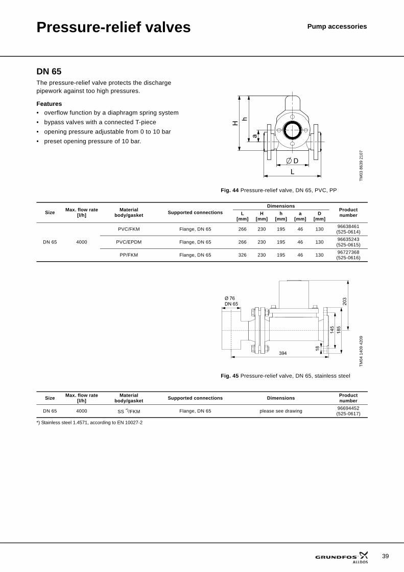
DN 65The pressure-relief valve protects the discharge pipework against too high pressures.
Features• overflow function by a diaphragm spring system• bypass valves with a connected T-piece• opening pressure adjustable from 0 to 10 bar• preset opening pressure of 10 bar.
*) Stainless steel 1.4571, according to EN 10027-2
TM03
863
9 21
07
Fig. 44 Pressure-relief valve, DN 65, PVC, PP
Size Max. flow rate[l/h]
Materialbody/gasket Supported connections
DimensionsProduct numberL
[mm]H
[mm]h
[mm]a
[mm]D
[mm]
DN 65 4000
PVC/FKM Flange, DN 65 266 230 195 46 130 96638461(525-0614)
PVC/EPDM Flange, DN 65 266 230 195 46 130 96635243(525-0615)
PP/FKM Flange, DN 65 326 230 195 46 130 96727368(525-0616)
TM04
140
9 42
09
Fig. 45 Pressure-relief valve, DN 65, stainless steel
394
185
203
18
Ø 76DN 65
145
Size Max. flow rate[l/h]
Materialbody/gasket Supported connections Dimensions Product
number
DN 65 4000 SS *)/FKM Flange, DN 65 please see drawing 96694452(525-0617)
39
40
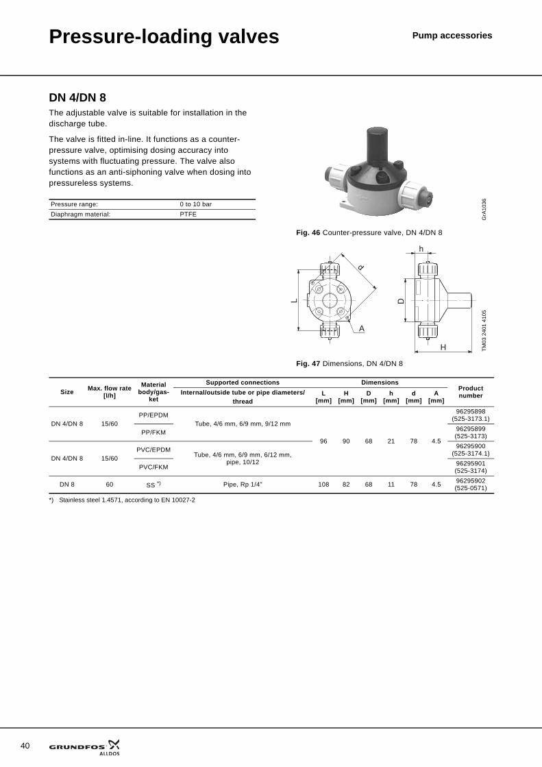
Pump accessoriesPressure-loading valves
DN 4/DN 8The adjustable valve is suitable for installation in the discharge tube.
The valve is fitted in-line. It functions as a counter-pressure valve, optimising dosing accuracy into systems with fluctuating pressure. The valve also functions as an anti-siphoning valve when dosing into pressureless systems.
*) Stainless steel 1.4571, according to EN 10027-2
Pressure range: 0 to 10 barDiaphragm material: PTFE
GrA
1036
Fig. 46 Counter-pressure valve, DN 4/DN 8
TM03
240
1 41
05
Fig. 47 Dimensions, DN 4/DN 8
Size Max. flow rate[l/h]
Material body/gas-
ket
Supported connections DimensionsProduct numberInternal/outside tube or pipe diameters/
threadL
[mm]H
[mm]D
[mm]h
[mm]d
[mm]A
[mm]
DN 4/DN 8 15/60PP/EPDM
Tube, 4/6 mm, 6/9 mm, 9/12 mm
96 90 68 21 78 4.5
96295898(525-3173.1)
PP/FKM 96295899(525-3173)
DN 4/DN 8 15/60PVC/EPDM
Tube, 4/6 mm, 6/9 mm, 6/12 mm,pipe, 10/12
96295900(525-3174.1)
PVC/FKM 96295901(525-3174)
DN 8 60 SS *) Pipe, Rp 1/4" 108 82 68 11 78 4.5 96295902(525-0571)
Pressure-loading valves Pump accessories
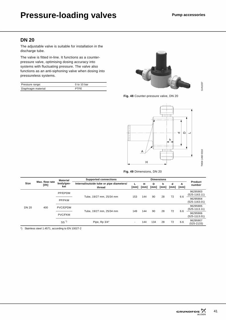
DN 20The adjustable valve is suitable for installation in the discharge tube.
The valve is fitted in-line. It functions as a counter-pressure valve, optimising dosing accuracy into systems with fluctuating pressure. The valve also functions as an anti-siphoning valve when dosing into pressureless systems.
*) Stainless steel 1.4571, according to EN 10027-2
Pressure range: 0 to 10 barDiaphragm material: PTFE G
rA10
37
Fig. 48 Counter-pressure valve, DN 20
TM04
146
0 03
10
Fig. 49 Dimensions, DN 20
A
H
h
d D L
Size Max. flow rate[l/h]
Material body/gas-
ket
Supported connections DimensionsProduct numberInternal/outside tube or pipe diameters/
threadL
[mm]H
[mm]D
[mm]h
[mm]d
[mm]A
[mm]
DN 20 400
PP/EPDMTube, 19/27 mm, 25/34 mm 153 144 90 28 72 6.6
96295903(525-1163.11)
PP/FKM 96295904(525-1163.01)
PVC/EPDMTube, 19/27 mm, 25/34 mm 149 144 90 28 72 6.6
96295905(525-1113.11)
PVC/FKM 96295906(525-1113.01)
SS *) Pipe, Rp 3/4" - 144 134 28 72 6.6 96295907(525-2133)
41
42
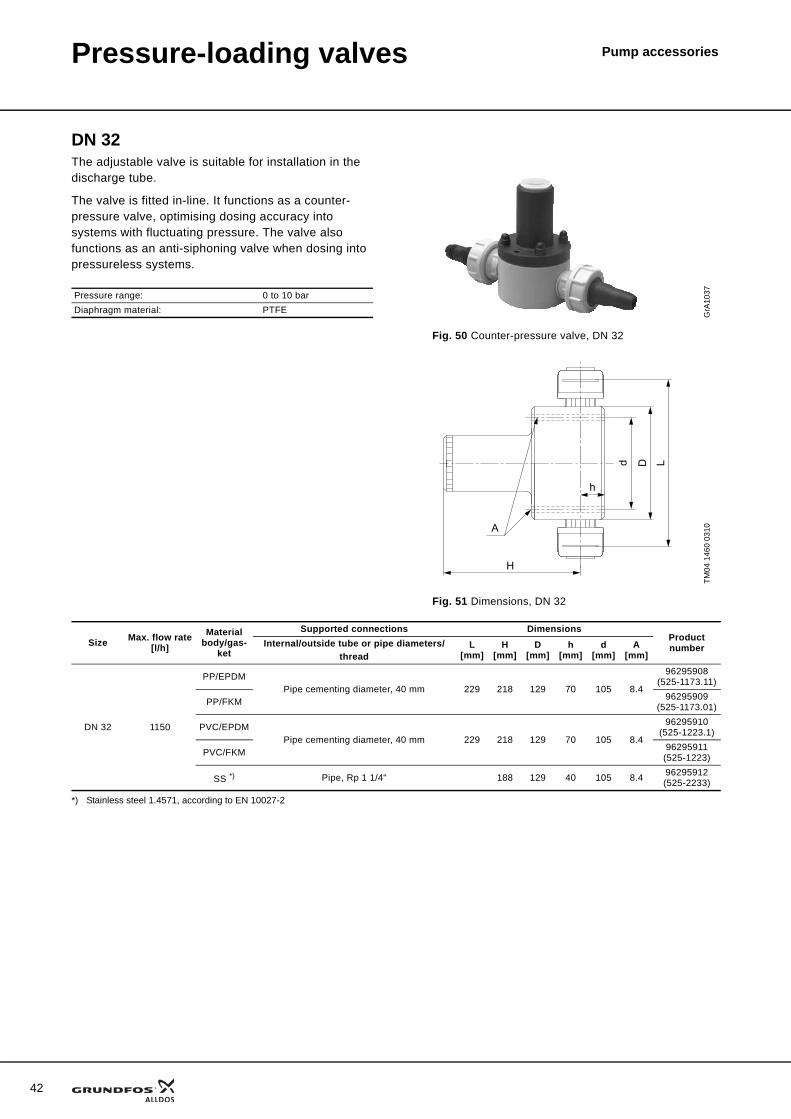
Pressure-loading valves Pump accessories
DN 32The adjustable valve is suitable for installation in the discharge tube.
The valve is fitted in-line. It functions as a counter-pressure valve, optimising dosing accuracy into systems with fluctuating pressure. The valve also functions as an anti-siphoning valve when dosing into pressureless systems.
*) Stainless steel 1.4571, according to EN 10027-2
Pressure range: 0 to 10 barDiaphragm material: PTFE G
rA10
37
Fig. 50 Counter-pressure valve, DN 32
TM04
146
0 03
10
Fig. 51 Dimensions, DN 32
A
H
h
d D LSize Max. flow rate
[l/h]Material
body/gas-ket
Supported connections DimensionsProduct numberInternal/outside tube or pipe diameters/
threadL
[mm]H
[mm]D
[mm]h
[mm]d
[mm]A
[mm]
DN 32 1150
PP/EPDMPipe cementing diameter, 40 mm 229 218 129 70 105 8.4
96295908(525-1173.11)
PP/FKM 96295909(525-1173.01)
PVC/EPDMPipe cementing diameter, 40 mm 229 218 129 70 105 8.4
96295910(525-1223.1)
PVC/FKM 96295911(525-1223)
SS *) Pipe, Rp 1 1/4" 188 129 40 105 8.4 96295912(525-2233)
Pressure-loading valves Pump accessories
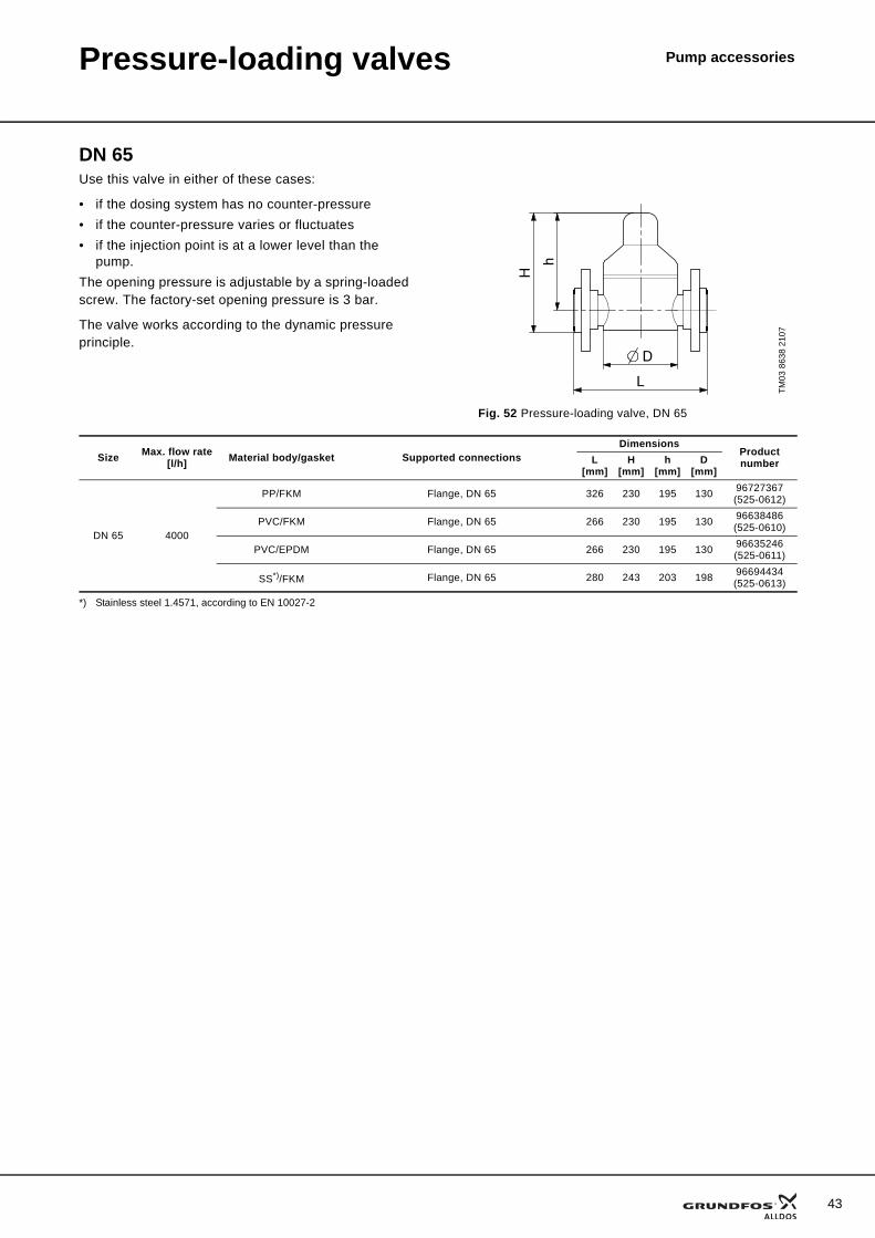
DN 65Use this valve in either of these cases:
• if the dosing system has no counter-pressure• if the counter-pressure varies or fluctuates• if the injection point is at a lower level than the
pump.The opening pressure is adjustable by a spring-loaded screw. The factory-set opening pressure is 3 bar.
The valve works according to the dynamic pressure principle.
*) Stainless steel 1.4571, according to EN 10027-2
TM03
863
8 21
07
Fig. 52 Pressure-loading valve, DN 65
Size Max. flow rate[l/h] Material body/gasket Supported connections
DimensionsProduct numberL
[mm]H
[mm]h
[mm]D
[mm]
DN 65 4000
PP/FKM Flange, DN 65 326 230 195 130 96727367(525-0612)
PVC/FKM Flange, DN 65 266 230 195 130 96638486(525-0610)
PVC/EPDM Flange, DN 65 266 230 195 130 96635246(525-0611)
SS*)/FKM Flange, DN 65 280 243 203 198 96694434(525-0613)
43
44
Pump accessoriesMulti-function valve
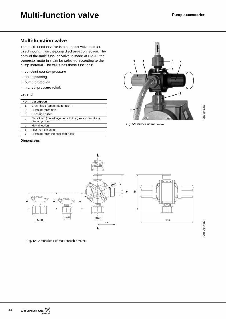
Multi-function valveThe multi-function valve is a compact valve unit for direct mounting on the pump discharge connection. The body of the multi-function valve is made of PVDF, the connector materials can be selected according to the pump material. The valve has these functions:
• constant counter-pressure• anti-siphoning• pump protection• manual pressure relief.
Legend
Dimensions
Pos. Description1 Green knob (turn for deaeration)2 Pressure-relief outlet3 Discharge outlet
4 Black knob (turned together with the green for emptying discharge line)
5 Flow direction6 Inlet from the pump7 Pressure-relief line back to the tank
TM
03 8
691
2207
Fig. 53 Multi-function valve
TM04
148
6 05
10
Fig. 54 Dimensions of multi-function valve
92
139
P S
451
47
45
G 5/8
Ø 60
G 3/8M 30
47 47
Multi-function valve Pump accessories
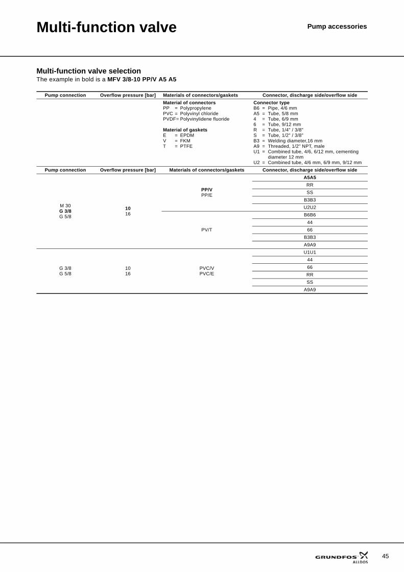
Multi-function valve selectionThe example in bold is a MFV 3/8-10 PP/V A5 A5
Pump connection Overflow pressure [bar] Materials of connectors/gaskets Connector, discharge side/overflow sideMaterial of connectorsPP = PolypropylenePVC = Polyvinyl chloridePVDF= Polyvinylidene fluoride
Material of gasketsE = EPDMV = FKMT = PTFE
Connector typeB6 = Pipe, 4/6 mmA5 = Tube, 5/8 mm4 = Tube, 6/9 mm6 = Tube, 9/12 mmR = Tube, 1/4" / 3/8"S = Tube, 1/2" / 3/8"B3 = Welding diameter,16 mmA9 = Threaded, 1/2" NPT, maleU1 = Combined tube, 4/6, 6/12 mm, cementing
diameter 12 mmU2 = Combined tube, 4/6 mm, 6/9 mm, 9/12 mm
Pump connection Overflow pressure [bar] Materials of connectors/gaskets Connector, discharge side/overflow side
M 30G 3/8G 5/8
1016
PP/VPP/E
A5A5RRSS
B3B3U2U2
PV/T
B6B64466
B3B3A9A9
G 3/8G 5/8
1016
PVC/VPVC/E
U1U14466RRSS
A9A9
45
46
Multi-function valve Pump accessories
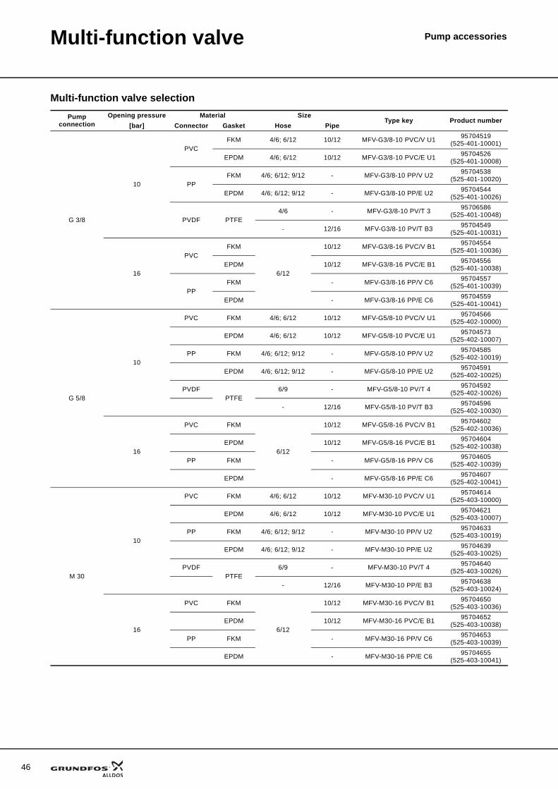
Multi-function valve selectionPump
connectionOpening pressure Material Size
Type key Product number[bar] Connector Gasket Hose Pipe
G 3/8
10
PVCFKM 4/6; 6/12 10/12 MFV-G3/8-10 PVC/V U1 95704519
(525-401-10001)
EPDM 4/6; 6/12 10/12 MFV-G3/8-10 PVC/E U1 95704526(525-401-10008)
PPFKM 4/6; 6/12; 9/12 - MFV-G3/8-10 PP/V U2 95704538
(525-401-10020)
EPDM 4/6; 6/12; 9/12 - MFV-G3/8-10 PP/E U2 95704544(525-401-10026)
PVDF PTFE4/6 - MFV-G3/8-10 PV/T 3 95706586
(525-401-10048)
- 12/16 MFV-G3/8-10 PV/T B3 95704549(525-401-10031)
16
PVCFKM
6/12
10/12 MFV-G3/8-16 PVC/V B1 95704554(525-401-10036)
EPDM 10/12 MFV-G3/8-16 PVC/E B1 95704556(525-401-10038)
PPFKM - MFV-G3/8-16 PP/V C6 95704557
(525-401-10039)
EPDM - MFV-G3/8-16 PP/E C6 95704559(525-401-10041)
G 5/8
10
PVC FKM 4/6; 6/12 10/12 MFV-G5/8-10 PVC/V U1 95704566(525-402-10000)
EPDM 4/6; 6/12 10/12 MFV-G5/8-10 PVC/E U1 95704573(525-402-10007)
PP FKM 4/6; 6/12; 9/12 - MFV-G5/8-10 PP/V U2 95704585(525-402-10019)
EPDM 4/6; 6/12; 9/12 - MFV-G5/8-10 PP/E U2 95704591(525-402-10025)
PVDFPTFE
6/9 - MFV-G5/8-10 PV/T 4 95704592(525-402-10026)
- 12/16 MFV-G5/8-10 PV/T B3 95704596(525-402-10030)
16
PVC FKM
6/12
10/12 MFV-G5/8-16 PVC/V B1 95704602(525-402-10036)
EPDM 10/12 MFV-G5/8-16 PVC/E B1 95704604(525-402-10038)
PP FKM - MFV-G5/8-16 PP/V C6 95704605(525-402-10039)
EPDM - MFV-G5/8-16 PP/E C6 95704607(525-402-10041)
M 30
10
PVC FKM 4/6; 6/12 10/12 MFV-M30-10 PVC/V U1 95704614(525-403-10000)
EPDM 4/6; 6/12 10/12 MFV-M30-10 PVC/E U1 95704621(525-403-10007)
PP FKM 4/6; 6/12; 9/12 - MFV-M30-10 PP/V U2 95704633(525-403-10019)
EPDM 4/6; 6/12; 9/12 - MFV-M30-10 PP/E U2 95704639(525-403-10025)
PVDFPTFE
6/9 - MFV-M30-10 PV/T 4 95704640(525-403-10026)
- 12/16 MFV-M30-10 PP/E B3 95704638(525-403-10024)
16
PVC FKM
6/12
10/12 MFV-M30-16 PVC/V B1 95704650(525-403-10036)
EPDM 10/12 MFV-M30-16 PVC/E B1 95704652(525-403-10038)
PP FKM - MFV-M30-16 PP/V C6 95704653(525-403-10039)
EPDM - MFV-M30-16 PP/E C6 95704655(525-403-10041)

Multi-function valve Pump accessories
Accessories for multi-function valveAdapter for DMI and DDI P3 pumpsWhen used with the multi-function valve, DMI and DDI dosing pumps with PVC dosing head and P3 system require an adapter. The adapter is fitted between the discharge port of the dosing head and the multi-function valve.
• Select a multifunction valve with G 5/8 pump connection
Adapter for pump Material Product number
For DMI and DDI pumps with PVC dosing head and P3 system
EPDM 95700954(529-483-1)
FKM 95700955(529-483-2)
47
48
Pump accessoriesPulsation dampers
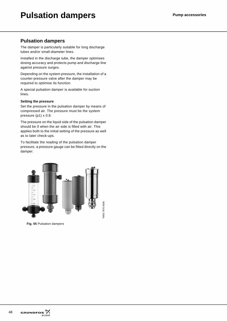
Pulsation dampersThe damper is particularly suitable for long discharge tubes and/or small-diameter lines.
Installed in the discharge tube, the damper optimises dosing accuracy and protects pump and discharge line against pressure surges.
Depending on the system pressure, the installation of a counter-pressure valve after the damper may be required to optimise its function.
A special pulsation damper is available for suction lines.
Setting the pressureSet the pressure in the pulsation damper by means of compressed air. The pressure must be the system pressure (p1) x 0.8.
The pressure on the liquid side of the pulsation damper should be 0 when the air side is filled with air. This applies both to the initial setting of the pressure as well as to later check-ups.
To facilitate the reading of the pulsation damper pressure, a pressure gauge can be fitted directly on the damper.
TM03
787
0 50
06
Fig. 55 Pulsation dampers
Pulsation dampers Pump accessories
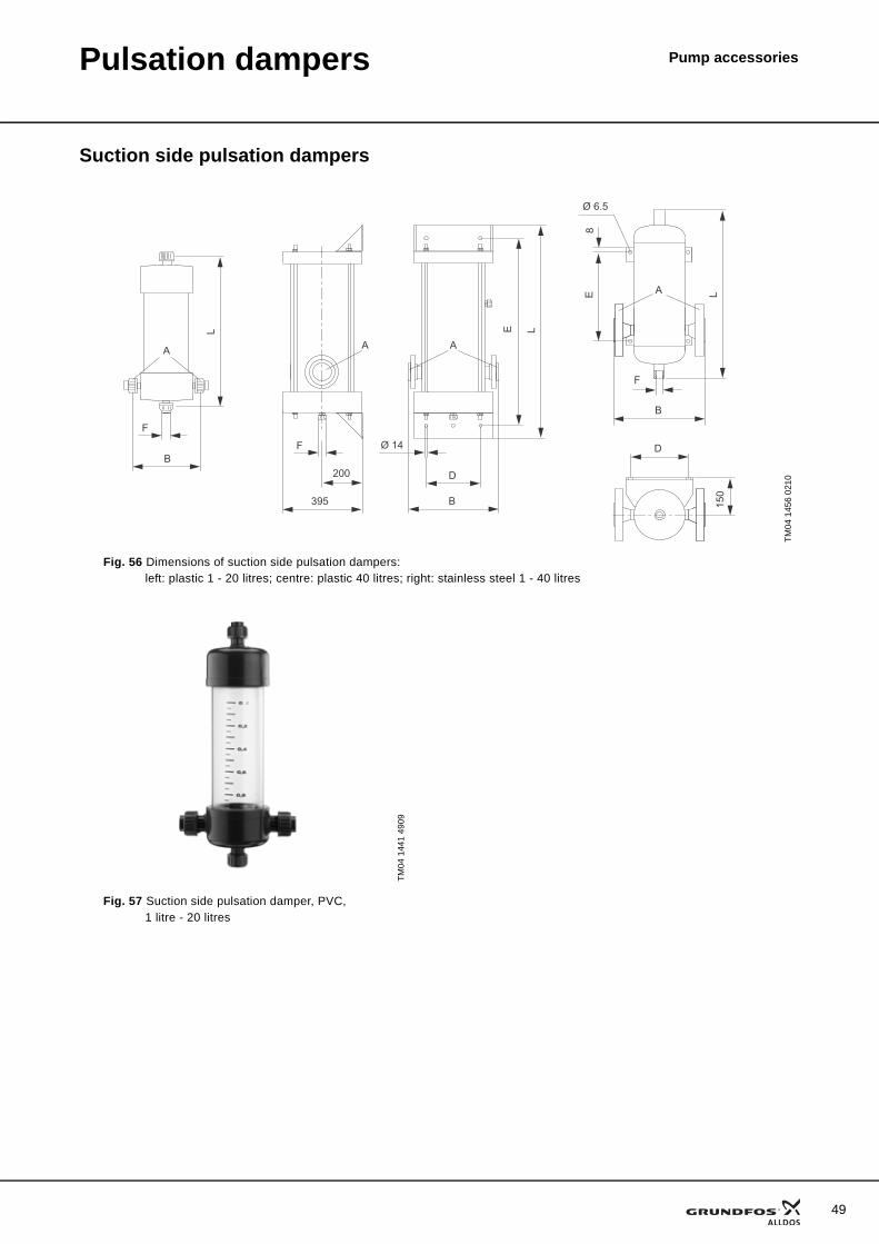
Suction side pulsation dampers
TM04
145
6 02
10
Fig. 56 Dimensions of suction side pulsation dampers: left: plastic 1 - 20 litres; centre: plastic 40 litres; right: stainless steel 1 - 40 litres
L
F
B
A
E
D
Ø 14
200
395 B
L
F
AA
D
150
B
8E L
F
Ø 6.5
A
TM04
144
1 49
09
Fig. 57 Suction side pulsation damper, PVC, 1 litre - 20 litres
49
50
Pulsation dampers Pump accessories
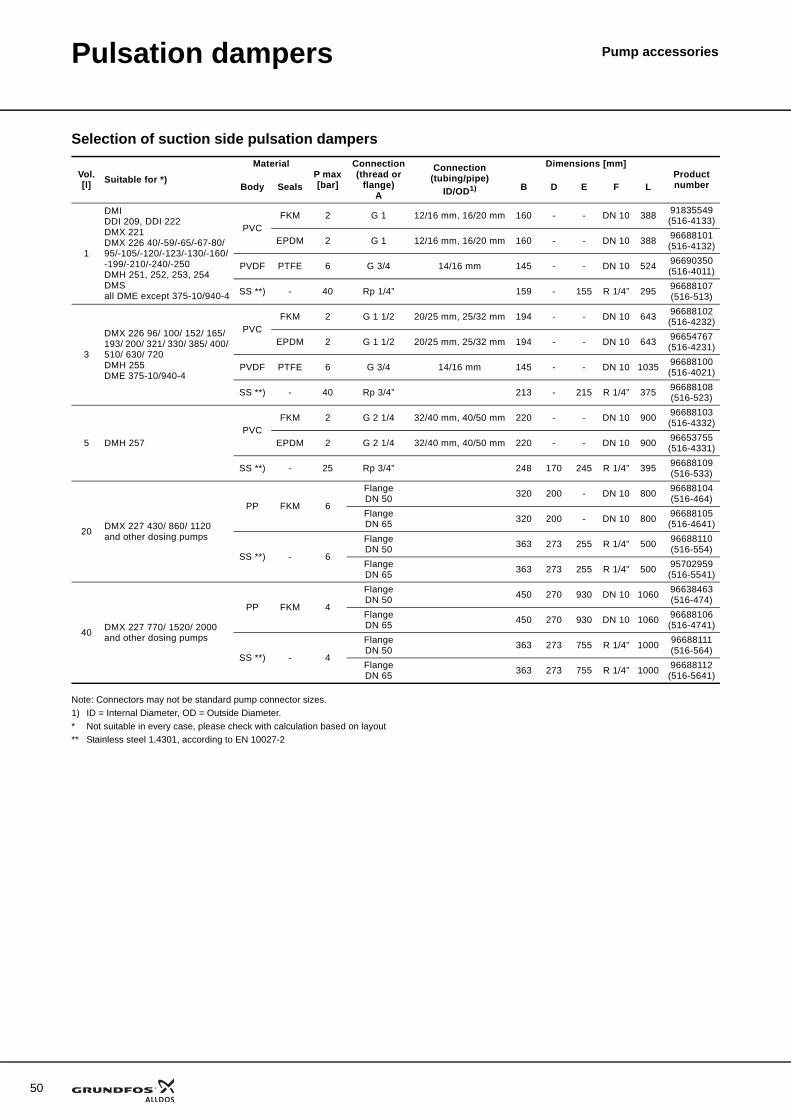
Selection of suction side pulsation dampers
Note: Connectors may not be standard pump connector sizes.1) ID = Internal Diameter, OD = Outside Diameter.* Not suitable in every case, please check with calculation based on layout** Stainless steel 1.4301, according to EN 10027-2
Vol.[l] Suitable for *)
MaterialP max [bar]
Connection (thread or
flange) A
Connection(tubing/pipe)
ID/OD1)
Dimensions [mm]Product numberBody Seals B D E F L
1
DMIDDI 209, DDI 222DMX 221DMX 226 40/-59/-65/-67-80/95/-105/-120/-123/-130/-160/-199/-210/-240/-250DMH 251, 252, 253, 254DMSall DME except 375-10/940-4
PVCFKM 2 G 1 12/16 mm, 16/20 mm 160 - - DN 10 388 91835549
(516-4133)
EPDM 2 G 1 12/16 mm, 16/20 mm 160 - - DN 10 388 96688101(516-4132)
PVDF PTFE 6 G 3/4 14/16 mm 145 - - DN 10 524 96690350(516-4011)
SS **) - 40 Rp 1/4” 159 - 155 R 1/4” 295 96688107(516-513)
3
DMX 226 96/ 100/ 152/ 165/ 193/ 200/ 321/ 330/ 385/ 400/ 510/ 630/ 720DMH 255DME 375-10/940-4
PVCFKM 2 G 1 1/2 20/25 mm, 25/32 mm 194 - - DN 10 643 96688102
(516-4232)
EPDM 2 G 1 1/2 20/25 mm, 25/32 mm 194 - - DN 10 643 96654767(516-4231)
PVDF PTFE 6 G 3/4 14/16 mm 145 - - DN 10 1035 96688100(516-4021)
SS **) - 40 Rp 3/4” 213 - 215 R 1/4” 375 96688108(516-523)
5 DMH 257PVC
FKM 2 G 2 1/4 32/40 mm, 40/50 mm 220 - - DN 10 900 96688103(516-4332)
EPDM 2 G 2 1/4 32/40 mm, 40/50 mm 220 - - DN 10 900 96653755(516-4331)
SS **) - 25 Rp 3/4” 248 170 245 R 1/4” 395 96688109(516-533)
20 DMX 227 430/ 860/ 1120and other dosing pumps
PP FKM 6
Flange DN 50 320 200 - DN 10 800 96688104
(516-464)Flange DN 65 320 200 - DN 10 800 96688105
(516-4641)
SS **) - 6
Flange DN 50 363 273 255 R 1/4” 500 96688110
(516-554)Flange DN 65 363 273 255 R 1/4” 500 95702959
(516-5541)
40 DMX 227 770/ 1520/ 2000and other dosing pumps
PP FKM 4
Flange DN 50 450 270 930 DN 10 1060 96638463
(516-474)Flange DN 65 450 270 930 DN 10 1060 96688106
(516-4741)
SS **) - 4
Flange DN 50 363 273 755 R 1/4” 1000 96688111
(516-564)Flange DN 65 363 273 755 R 1/4” 1000 96688112
(516-5641)
Pulsation dampers Pump accessories
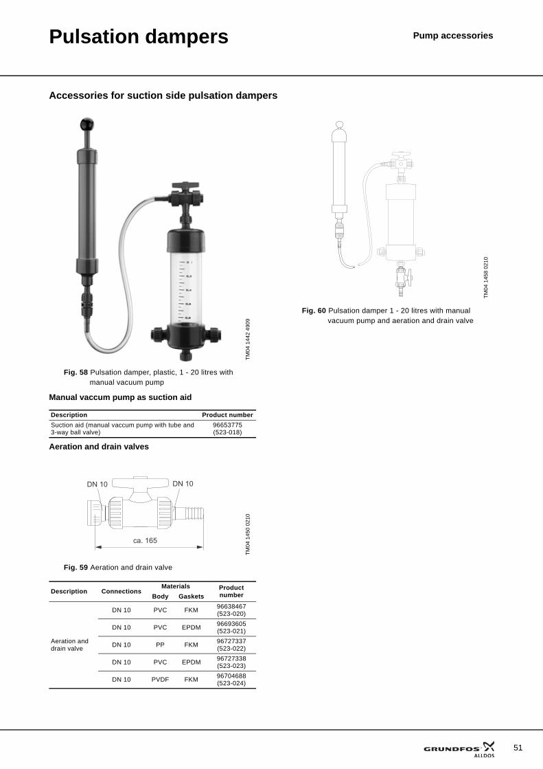
Accessories for suction side pulsation dampers
Manual vaccum pump as suction aid
Aeration and drain valves
TM04
144
2 49
09
Fig. 58 Pulsation damper, plastic, 1 - 20 litres with manual vacuum pump
Description Product numberSuction aid (manual vaccum pump with tube and 3-way ball valve)
96653775(523-018)
TM04
145
0 02
10
Fig. 59 Aeration and drain valve
Description ConnectionsMaterials Product
numberBody Gaskets
Aeration and drain valve
DN 10 PVC FKM 96638467(523-020)
DN 10 PVC EPDM 96693605(523-021)
DN 10 PP FKM 96727337(523-022)
DN 10 PVC EPDM 96727338(523-023)
DN 10 PVDF FKM 96704688(523-024)
ca. 165
DN 10DN 10TM
04 1
458
0210
Fig. 60 Pulsation damper 1 - 20 litres with manual vacuum pump and aeration and drain valve
51
52
Pulsation dampers Pump accessories
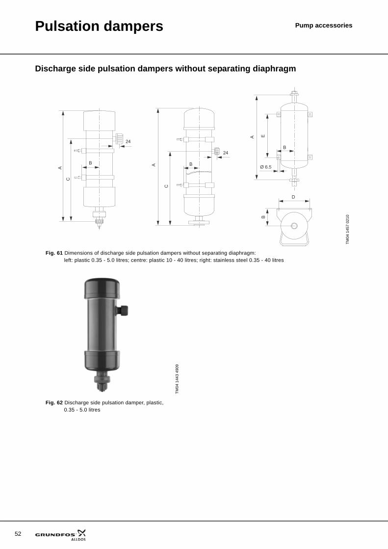
Discharge side pulsation dampers without separating diaphragm
TM04
145
7 02
10
Fig. 61 Dimensions of discharge side pulsation dampers without separating diaphragm: left: plastic 0.35 - 5.0 litres; centre: plastic 10 - 40 litres; right: stainless steel 0.35 - 40 litres
A
C
24
B BA
C
24
A
Ø 6.5
E
D
B
B
TM04
144
3 49
09
Fig. 62 Discharge side pulsation damper, plastic, 0.35 - 5.0 litres
Pulsation dampers Pump accessories
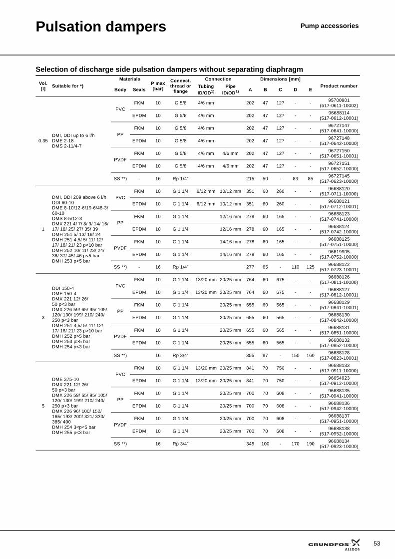
Selection of discharge side pulsation dampers without separating diaphragm
Vol.[l] Suitable for *)
MaterialsP max[bar]
Connect. thread or
flange
Connection Dimensions [mm]Product number
Body SealsTubingID/OD1)
PipeID/OD1) A B C D E
0.35DMI, DDI up to 6 l/hDME 2-18DMS 2-11/4-7
PVCFKM 10 G 5/8 4/6 mm 202 47 127 - - 95700901
(517-0611-10002)
EPDM 10 G 5/8 4/6 mm 202 47 127 - - 96688114(517-0612-10001)
PPFKM 10 G 5/8 4/6 mm 202 47 127 - - 96727147
(517-0641-10000)
EPDM 10 G 5/8 4/6 mm 202 47 127 - - 96727148(517-0642-10000)
PVDFFKM 10 G 5/8 4/6 mm 4/6 mm 202 47 127 - - 96727150
(517-0651-10001)
EPDM 10 G 5/8 4/6 mm 4/6 mm 202 47 127 - - 96727151(517-0652-10000)
SS **) - 16 Rp 1/4” 215 50 - 83 85 96727145(517-0623-10000)
1
DMI, DDI 209 above 6 l/hDDI 60-10DME 8-10/12-6/19-6/48-3/60-10DMS 8-5/12-3DMX 221 4/ 7/ 8/ 9/ 14/ 16/ 17/ 18/ 25/ 27/ 35/ 39DMH 251 5/ 13/ 19/ 24DMH 251 4,5/ 5/ 11/ 12/ 17/ 18/ 21/ 23 p<10 barDMH 252 10/ 11/ 23/ 24/ 36/ 37/ 45/ 46 p<5 barDMH 253 p<5 bar
PVCFKM 10 G 1 1/4 6/12 mm 10/12 mm 351 60 260 - - 96688120
(517-0711-10000)
EPDM 10 G 1 1/4 6/12 mm 10/12 mm 351 60 260 - - 96688121(517-0712-10001)
PPFKM 10 G 1 1/4 12/16 mm 278 60 165 - - 96688123
(517-0741-10000)
EPDM 10 G 1 1/4 12/16 mm 278 60 165 - - 96688124(517-0742-10000)
PVDFFKM 10 G 1 1/4 14/16 mm 278 60 165 - - 96688125
(517-0751-10000)
EPDM 10 G 1 1/4 14/16 mm 278 60 165 - - 96619905(517-0752-10000)
SS **) - 16 Rp 1/4” 277 65 - 110 125 96688122(517-0723-10001)
3
DDI 150-4DME 150-4DMX 221 12/ 26/ 50 p<3 barDMX 226 59/ 65/ 95/ 105/ 120/ 130/ 199/ 210/ 240/ 250 p<3 barDMH 251 4,5/ 5/ 11/ 12/ 17/ 18/ 21/ 23 p>10 barDMH 252 p>5 barDMH 253 p>5 barDMH 254 p<3 bar
PVCFKM 10 G 1 1/4 13/20 mm 20/25 mm 764 60 675 - - 96688126
(517-0811-10000)
EPDM 10 G 1 1/4 13/20 mm 20/25 mm 764 60 675 - - 96688127(517-0812-10001)
PPFKM 10 G 1 1/4 20/25 mm 655 60 565 - - 96688129
(517-0841-10001)
EPDM 10 G 1 1/4 20/25 mm 655 60 565 - - 96688130(517-0842-10000)
PVDFFKM 10 G 1 1/4 20/25 mm 655 60 565 - - 96688131
(517-0851-10000)
EPDM 10 G 1 1/4 20/25 mm 655 60 565 - - 96688132(517-0852-10000)
SS **) 16 Rp 3/4” 355 87 - 150 160 96688128(517-0823-10001)
5
DME 375-10DMX 221 12/ 26/ 50 p>3 barDMX 226 59/ 65/ 95/ 105/ 120/ 130/ 199/ 210/ 240/ 250 p>3 barDMX 226 96/ 100/ 152/ 165/ 193/ 200/ 321/ 330/ 385/ 400DMH 254 3<p<5 barDMH 255 p<3 bar
PVCFKM 10 G 1 1/4 13/20 mm 20/25 mm 841 70 750 - - 96688133
(517-0911-10000)
EPDM 10 G 1 1/4 13/20 mm 20/25 mm 841 70 750 - - 96654923(517-0912-10000)
PPFKM 10 G 1 1/4 20/25 mm 700 70 608 - - 96688135
(517-0941-10000)
EPDM 10 G 1 1/4 20/25 mm 700 70 608 - - 96688136(517-0942-10000)
PVDFFKM 10 G 1 1/4 20/25 mm 700 70 608 - - 96688137
(517-0951-10000)
EPDM 10 G 1 1/4 20/25 mm 700 70 608 - - 96688138(517-0952-10000)
SS **) 16 Rp 3/4” 345 100 - 170 190 96688134(517-0923-10000)
53
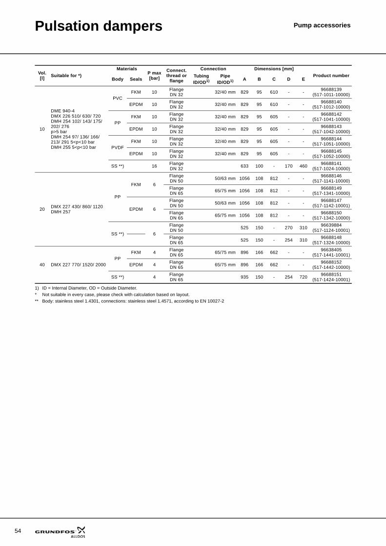
54
Pulsation dampers Pump accessories
1) ID = Internal Diameter, OD = Outside Diameter.* Not suitable in every case, please check with calculation based on layout.** Body: stainless steel 1.4301, connections: stainless steel 1.4571, according to EN 10027-2
10
DME 940-4DMX 226 510/ 630/ 720DMH 254 102/ 143/ 175/ 202/ 276p>5 barDMH 254 97/ 136/ 166/ 213/ 291 5<p<10 barDMH 255 5<p<10 bar
PVCFKM 10 Flange
DN 32 32/40 mm 829 95 610 - - 96688139(517-1011-10000)
EPDM 10 FlangeDN 32 32/40 mm 829 95 610 - - 96688140
(517-1012-10000)
PPFKM 10 Flange
DN 32 32/40 mm 829 95 605 - - 96688142(517-1041-10000)
EPDM 10 FlangeDN 32 32/40 mm 829 95 605 - - 96688143
(517-1042-10000)
PVDFFKM 10 Flange
DN 32 32/40 mm 829 95 605 - - 96688144(517-1051-10000)
EPDM 10 FlangeDN 32 32/40 mm 829 95 605 - - 96688145
(517-1052-10000)
SS **) 16 FlangeDN 32 633 100 - 170 460 96688141
(517-1024-10000)
20 DMX 227 430/ 860/ 1120DMH 257
PP
FKM 6
FlangeDN 50 50/63 mm 1056 108 812 - - 96688146
(517-1141-10000)FlangeDN 65 65/75 mm 1056 108 812 - - 96688149
(517-1341-10000)
EPDM 6
FlangeDN 50 50/63 mm 1056 108 812 - - 96688147
(517-1142-10001)FlangeDN 65 65/75 mm 1056 108 812 - - 96688150
(517-1342-10000)
SS **) 6
FlangeDN 50 525 150 - 270 310 96639884
(517-1124-10001)FlangeDN 65 525 150 - 254 310 96688148
(517-1324-10000)
40 DMX 227 770/ 1520/ 2000PP
FKM 4 FlangeDN 65 65/75 mm 896 166 662 - - 96638405
(517-1441-10001)
EPDM 4 FlangeDN 65 65/75 mm 896 166 662 - - 96688152
(517-1442-10000)
SS **) 4 FlangeDN 65 935 150 - 254 720 96688151
(517-1424-10001)
Vol.[l] Suitable for *)
MaterialsP max[bar]
Connect. thread or
flange
Connection Dimensions [mm]Product number
Body SealsTubingID/OD1)
PipeID/OD1) A B C D E
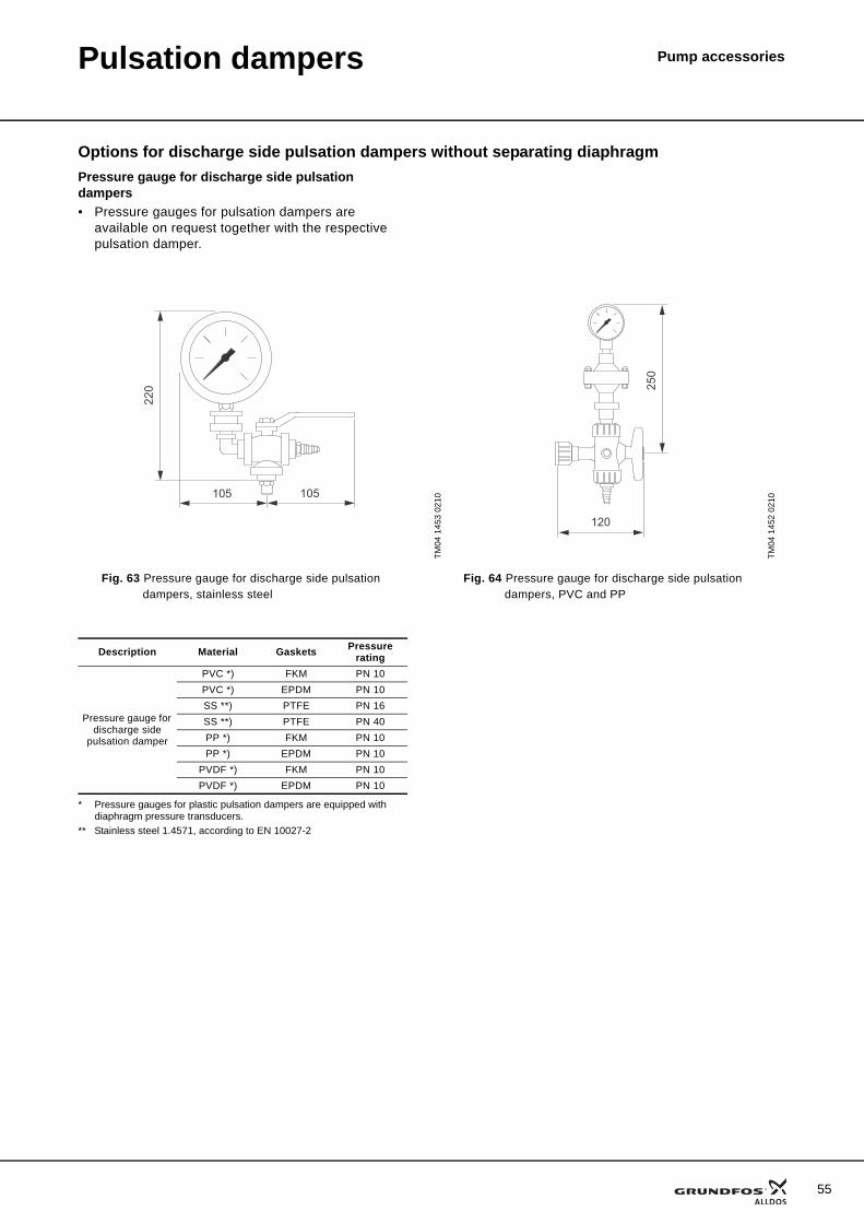
Pulsation dampers Pump accessories
Options for discharge side pulsation dampers without separating diaphragmPressure gauge for discharge side pulsation dampers• Pressure gauges for pulsation dampers are
available on request together with the respective pulsation damper.
* Pressure gauges for plastic pulsation dampers are equipped with diaphragm pressure transducers.
** Stainless steel 1.4571, according to EN 10027-2
TM04
145
3 02
10
TM04
145
2 02
10
Fig. 63 Pressure gauge for discharge side pulsation dampers, stainless steel
Fig. 64 Pressure gauge for discharge side pulsation dampers, PVC and PP
105 105
220
120
250
Description Material Gaskets Pressure rating
Pressure gauge for discharge side
pulsation damper
PVC *) FKM PN 10PVC *) EPDM PN 10SS **) PTFE PN 16SS **) PTFE PN 40PP *) FKM PN 10PP *) EPDM PN 10
PVDF *) FKM PN 10PVDF *) EPDM PN 10
55
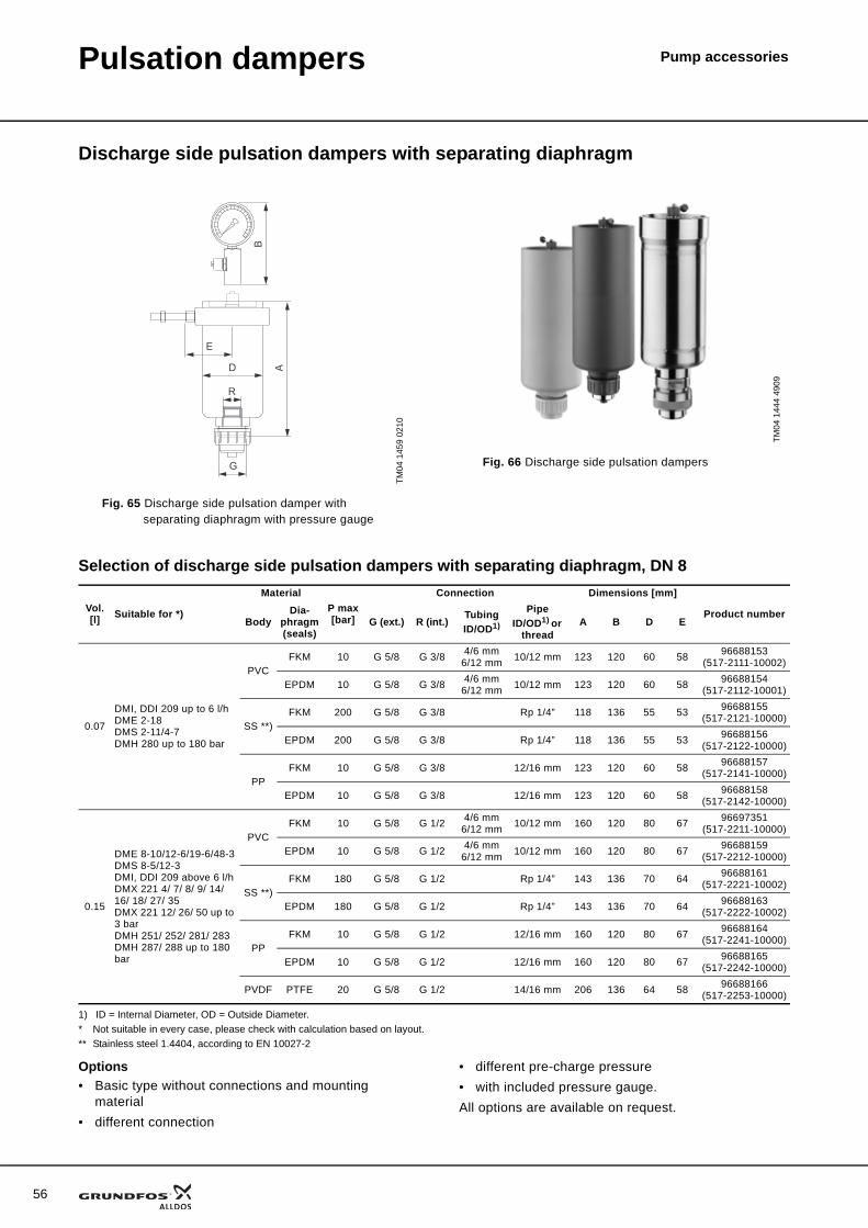
56
Pulsation dampers Pump accessories
Discharge side pulsation dampers with separating diaphragm
Selection of discharge side pulsation dampers with separating diaphragm, DN 8
1) ID = Internal Diameter, OD = Outside Diameter.* Not suitable in every case, please check with calculation based on layout.** Stainless steel 1.4404, according to EN 10027-2
Options• Basic type without connections and mounting
material• different connection
• different pre-charge pressure• with included pressure gauge.All options are available on request.
TM04
145
9 02
10
Fig. 65 Discharge side pulsation damper with separating diaphragm with pressure gauge
0
0
0
0
E
D
G
A
R
B
TM04
144
4 49
09
Fig. 66 Discharge side pulsation dampers
Vol.[l] Suitable for *)
MaterialP max[bar]
Connection Dimensions [mm]
Product numberBody
Dia-phragm (seals)
G (ext.) R (int.)TubingID/OD1)
PipeID/OD1) or
threadA B D E
0.07
DMI, DDI 209 up to 6 l/hDME 2-18DMS 2-11/4-7DMH 280 up to 180 bar
PVCFKM 10 G 5/8 G 3/8 4/6 mm
6/12 mm 10/12 mm 123 120 60 58 96688153(517-2111-10002)
EPDM 10 G 5/8 G 3/8 4/6 mm6/12 mm 10/12 mm 123 120 60 58 96688154
(517-2112-10001)
SS **)FKM 200 G 5/8 G 3/8 Rp 1/4” 118 136 55 53 96688155
(517-2121-10000)
EPDM 200 G 5/8 G 3/8 Rp 1/4” 118 136 55 53 96688156(517-2122-10000)
PPFKM 10 G 5/8 G 3/8 12/16 mm 123 120 60 58 96688157
(517-2141-10000)
EPDM 10 G 5/8 G 3/8 12/16 mm 123 120 60 58 96688158(517-2142-10000)
0.15
DME 8-10/12-6/19-6/48-3DMS 8-5/12-3DMI, DDI 209 above 6 l/hDMX 221 4/ 7/ 8/ 9/ 14/ 16/ 18/ 27/ 35DMX 221 12/ 26/ 50 up to 3 barDMH 251/ 252/ 281/ 283DMH 287/ 288 up to 180 bar
PVCFKM 10 G 5/8 G 1/2 4/6 mm
6/12 mm 10/12 mm 160 120 80 67 96697351(517-2211-10000)
EPDM 10 G 5/8 G 1/2 4/6 mm6/12 mm 10/12 mm 160 120 80 67 96688159
(517-2212-10000)
SS **)FKM 180 G 5/8 G 1/2 Rp 1/4” 143 136 70 64 96688161
(517-2221-10002)
EPDM 180 G 5/8 G 1/2 Rp 1/4” 143 136 70 64 96688163(517-2222-10002)
PPFKM 10 G 5/8 G 1/2 12/16 mm 160 120 80 67 96688164
(517-2241-10000)
EPDM 10 G 5/8 G 1/2 12/16 mm 160 120 80 67 96688165(517-2242-10000)
PVDF PTFE 20 G 5/8 G 1/2 14/16 mm 206 136 64 58 96688166(517-2253-10000)
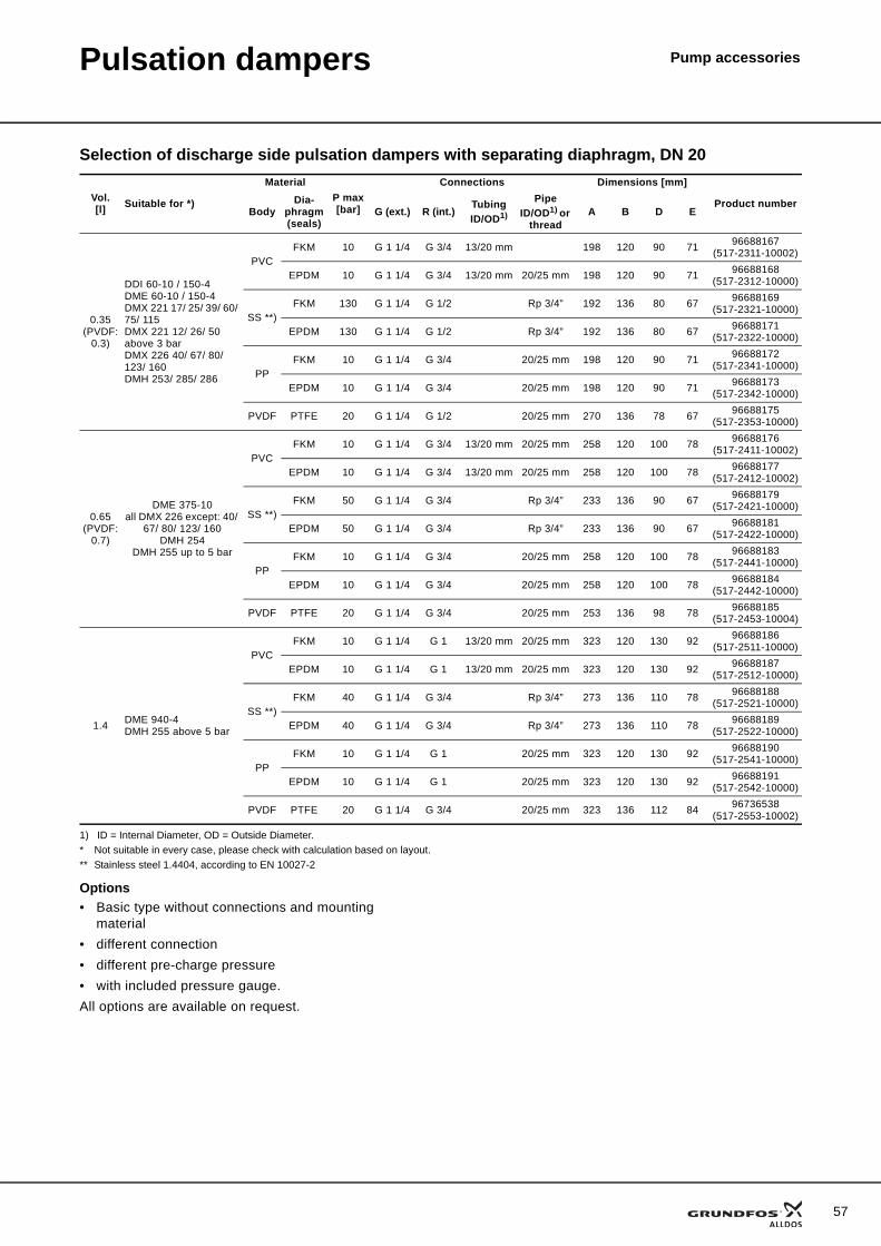
Pulsation dampers Pump accessories
Selection of discharge side pulsation dampers with separating diaphragm, DN 20
1) ID = Internal Diameter, OD = Outside Diameter.* Not suitable in every case, please check with calculation based on layout.** Stainless steel 1.4404, according to EN 10027-2
Options• Basic type without connections and mounting
material• different connection• different pre-charge pressure• with included pressure gauge.All options are available on request.
Vol.[l] Suitable for *)
MaterialP max[bar]
Connections Dimensions [mm]
Product numberBody
Dia-phragm (seals)
G (ext.) R (int.)TubingID/OD1)
PipeID/OD1) or
threadA B D E
0.35(PVDF:
0.3)
DDI 60-10 / 150-4DME 60-10 / 150-4DMX 221 17/ 25/ 39/ 60/ 75/ 115DMX 221 12/ 26/ 50 above 3 barDMX 226 40/ 67/ 80/ 123/ 160DMH 253/ 285/ 286
PVCFKM 10 G 1 1/4 G 3/4 13/20 mm 198 120 90 71 96688167
(517-2311-10002)
EPDM 10 G 1 1/4 G 3/4 13/20 mm 20/25 mm 198 120 90 71 96688168(517-2312-10000)
SS **)FKM 130 G 1 1/4 G 1/2 Rp 3/4” 192 136 80 67 96688169
(517-2321-10000)
EPDM 130 G 1 1/4 G 1/2 Rp 3/4” 192 136 80 67 96688171(517-2322-10000)
PPFKM 10 G 1 1/4 G 3/4 20/25 mm 198 120 90 71 96688172
(517-2341-10000)
EPDM 10 G 1 1/4 G 3/4 20/25 mm 198 120 90 71 96688173(517-2342-10000)
PVDF PTFE 20 G 1 1/4 G 1/2 20/25 mm 270 136 78 67 96688175(517-2353-10000)
0.65(PVDF:
0.7)
DME 375-10all DMX 226 except: 40/
67/ 80/ 123/ 160DMH 254
DMH 255 up to 5 bar
PVCFKM 10 G 1 1/4 G 3/4 13/20 mm 20/25 mm 258 120 100 78 96688176
(517-2411-10002)
EPDM 10 G 1 1/4 G 3/4 13/20 mm 20/25 mm 258 120 100 78 96688177(517-2412-10002)
SS **)FKM 50 G 1 1/4 G 3/4 Rp 3/4” 233 136 90 67 96688179
(517-2421-10000)
EPDM 50 G 1 1/4 G 3/4 Rp 3/4” 233 136 90 67 96688181(517-2422-10000)
PPFKM 10 G 1 1/4 G 3/4 20/25 mm 258 120 100 78 96688183
(517-2441-10000)
EPDM 10 G 1 1/4 G 3/4 20/25 mm 258 120 100 78 96688184(517-2442-10000)
PVDF PTFE 20 G 1 1/4 G 3/4 20/25 mm 253 136 98 78 96688185(517-2453-10004)
1.4 DME 940-4DMH 255 above 5 bar
PVCFKM 10 G 1 1/4 G 1 13/20 mm 20/25 mm 323 120 130 92 96688186
(517-2511-10000)
EPDM 10 G 1 1/4 G 1 13/20 mm 20/25 mm 323 120 130 92 96688187(517-2512-10000)
SS **)FKM 40 G 1 1/4 G 3/4 Rp 3/4” 273 136 110 78 96688188
(517-2521-10000)
EPDM 40 G 1 1/4 G 3/4 Rp 3/4” 273 136 110 78 96688189(517-2522-10000)
PPFKM 10 G 1 1/4 G 1 20/25 mm 323 120 130 92 96688190
(517-2541-10000)
EPDM 10 G 1 1/4 G 1 20/25 mm 323 120 130 92 96688191(517-2542-10000)
PVDF PTFE 20 G 1 1/4 G 3/4 20/25 mm 323 136 112 84 96736538(517-2553-10002)
57
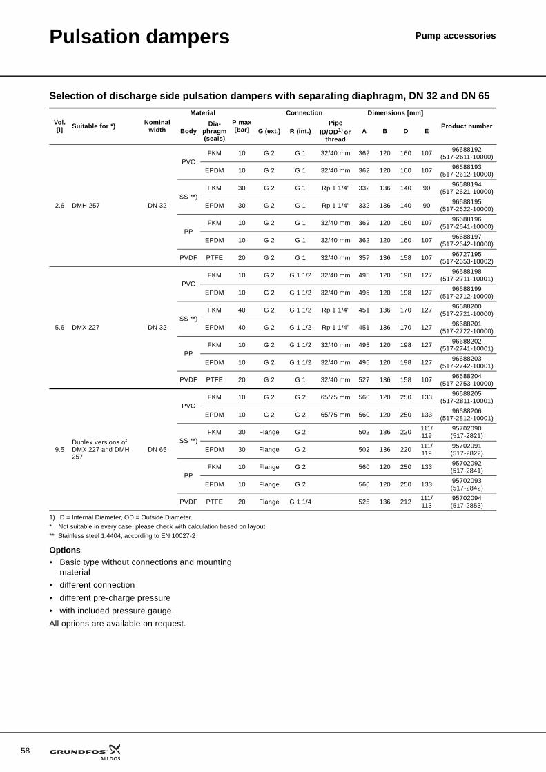
58
Pulsation dampers Pump accessories
Selection of discharge side pulsation dampers with separating diaphragm, DN 32 and DN 65
1) ID = Internal Diameter, OD = Outside Diameter.* Not suitable in every case, please check with calculation based on layout.** Stainless steel 1.4404, according to EN 10027-2
Options• Basic type without connections and mounting
material• different connection• different pre-charge pressure• with included pressure gauge.All options are available on request.
Vol.[l] Suitable for *) Nominal
width
MaterialP max[bar]
Connection Dimensions [mm]
Product numberBody
Dia-phragm (seals)
G (ext.) R (int.)Pipe
ID/OD1) or thread
A B D E
2.6 DMH 257 DN 32
PVCFKM 10 G 2 G 1 32/40 mm 362 120 160 107 96688192
(517-2611-10000)
EPDM 10 G 2 G 1 32/40 mm 362 120 160 107 96688193(517-2612-10000)
SS **)FKM 30 G 2 G 1 Rp 1 1/4” 332 136 140 90 96688194
(517-2621-10000)
EPDM 30 G 2 G 1 Rp 1 1/4” 332 136 140 90 96688195(517-2622-10000)
PPFKM 10 G 2 G 1 32/40 mm 362 120 160 107 96688196
(517-2641-10000)
EPDM 10 G 2 G 1 32/40 mm 362 120 160 107 96688197(517-2642-10000)
PVDF PTFE 20 G 2 G 1 32/40 mm 357 136 158 107 96727195(517-2653-10002)
5.6 DMX 227 DN 32
PVCFKM 10 G 2 G 1 1/2 32/40 mm 495 120 198 127 96688198
(517-2711-10001)
EPDM 10 G 2 G 1 1/2 32/40 mm 495 120 198 127 96688199(517-2712-10000)
SS **)FKM 40 G 2 G 1 1/2 Rp 1 1/4” 451 136 170 127 96688200
(517-2721-10000)
EPDM 40 G 2 G 1 1/2 Rp 1 1/4” 451 136 170 127 96688201(517-2722-10000)
PPFKM 10 G 2 G 1 1/2 32/40 mm 495 120 198 127 96688202
(517-2741-10001)
EPDM 10 G 2 G 1 1/2 32/40 mm 495 120 198 127 96688203(517-2742-10001)
PVDF PTFE 20 G 2 G 1 32/40 mm 527 136 158 107 96688204(517-2753-10000)
9.5Duplex versions of DMX 227 and DMH 257
DN 65
PVCFKM 10 G 2 G 2 65/75 mm 560 120 250 133 96688205
(517-2811-10001)
EPDM 10 G 2 G 2 65/75 mm 560 120 250 133 96688206(517-2812-10001)
SS **)FKM 30 Flange G 2 502 136 220 111/
11995702090(517-2821)
EPDM 30 Flange G 2 502 136 220 111/119
95702091(517-2822)
PPFKM 10 Flange G 2 560 120 250 133 95702092
(517-2841)
EPDM 10 Flange G 2 560 120 250 133 95702093(517-2842)
PVDF PTFE 20 Flange G 1 1/4 525 136 212 111/113
95702094(517-2853)
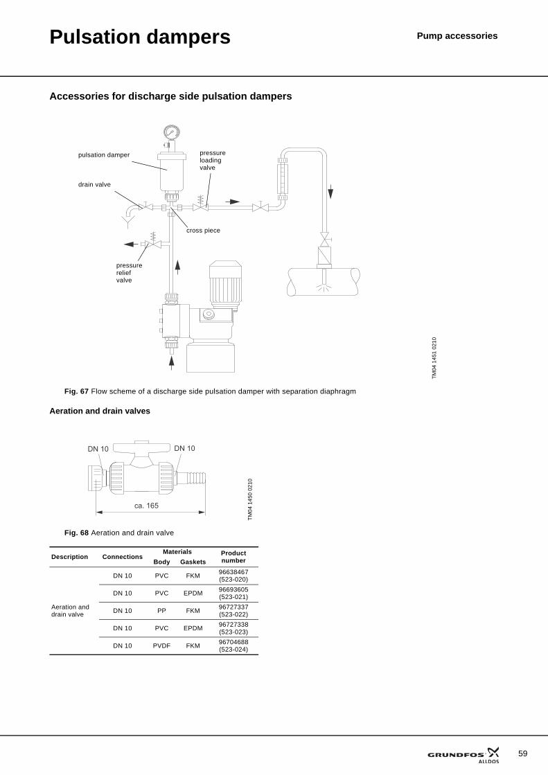
Pulsation dampers Pump accessories
Accessories for discharge side pulsation dampers
Aeration and drain valves
TM04
145
1 02
10
Fig. 67 Flow scheme of a discharge side pulsation damper with separation diaphragm
cross piece
pressure loading valve
TM04
145
0 02
10
Fig. 68 Aeration and drain valve
Description ConnectionsMaterials Product
numberBody Gaskets
Aeration and drain valve
DN 10 PVC FKM 96638467(523-020)
DN 10 PVC EPDM 96693605(523-021)
DN 10 PP FKM 96727337(523-022)
DN 10 PVC EPDM 96727338(523-023)
DN 10 PVDF FKM 96704688(523-024)
ca. 165
DN 10DN 10
pulsation damper
drain valve
pressure relief valve
59
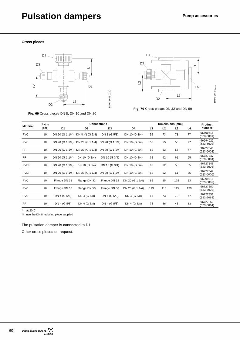
60
Pulsation dampers Pump accessories
Cross pieces
* at 20°C** use the DN 8 reducing piece supplied
The pulsation damper is connected to D1.
Other cross pieces on request.
TM04
144
8 02
10
Fig. 69 Cross pieces DN 8, DN 10 and DN 20
L1
L2
L3
D1
D2
D2
D3
TM04
144
9 02
10
Fig. 70 Cross pieces DN 32 and DN 50
L3
L2
L1
D1
D2
D2
D3
Material PN *) [bar]
Connections Dimensions [mm] Product numberD1 D2 D3 D4 L1 L2 L3 L4
PVC 10 DN 20 (G 1 1/4) DN 8 **) (G 5/8) DN 8 (G 5/8) DN 10 (G 3/4) 55 73 73 77 96699618(523-6001)
PVC 10 DN 20 (G 1 1/4) DN 20 (G 1 1/4) DN 20 (G 1 1/4) DN 10 (G 3/4) 55 55 55 77 96694022(523-6002)
PP 10 DN 20 (G 1 1/4) DN 20 (G 1 1/4) DN 20 (G 1 1/4) DN 10 (G 3/4) 62 62 55 77 96727346(523-6003)
PP 10 DN 20 (G 1 1/4) DN 10 (G 3/4) DN 10 (G 3/4) DN 10 (G 3/4) 62 62 61 55 96727347(523-6004)
PVDF 10 DN 20 (G 1 1/4) DN 10 (G 3/4) DN 10 (G 3/4) DN 10 (G 3/4) 62 62 55 55 96727348(523-6005)
PVDF 10 DN 20 (G 1 1/4) DN 20 (G 1 1/4) DN 20 (G 1 1/4) DN 10 (G 3/4) 62 62 61 55 96727349(523-6006)
PVC 10 Flange DN 32 Flange DN 32 Flange DN 32 DN 20 (G 1 1/4) 85 85 125 83 96699615(523-6007)
PVC 10 Flange DN 50 Flange DN 50 Flange DN 50 DN 20 (G 1 1/4) 113 113 115 139 96727350(523-6008)
PVC 10 DN 4 (G 5/8) DN 4 (G 5/8) DN 4 (G 5/8) DN 4 (G 5/8) 66 73 73 77 96727351(523-6063)
PP 10 DN 4 (G 5/8) DN 4 (G 5/8) DN 4 (G 5/8) DN 4 (G 5/8) 73 66 45 53 96727352(523-6064)
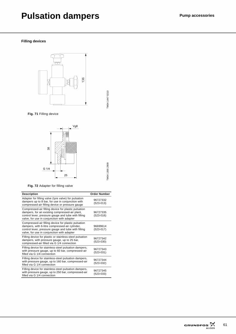
Pulsation dampers Pump accessories
Filling devices
TM04
144
7 02
10
Fig. 71 Filling device
TM04
135
5 29
09
Fig. 72 Adapter for filling valve
Description Order NumberAdapter for filling valve (tyre valve) for pulsation dampers up to 8 bar, for use in conjunction with compressed-air filling device or pressure gauge
96727332(523-013)
Compressed-air filling device for plastic pulsation dampers, for an existing compressed-air plant, control lever, pressure gauge and tube with filling valve, for use in conjunction with adapter
96727335(523-016)
Compressed-air filling device for plastic pulsation dampers, with 6-litre compressed-air cylinder, control lever, pressure gauge and tube with filling valve, for use in conjunction with adapter
96699614(523-017)
Filling device for plastic or stainless-steel pulsation dampers, with pressure gauge, up to 25 bar, compressed-air filled via G 1/4 connection
96727342(523-030)
Filling device for stainless-steel pulsation dampers, with pressure gauge, up to 60 bar, compressed-air filled via G 1/4 connection
96727343(523-031)
Filling device for stainless-steel pulsation dampers, with pressure gauge, up to 160 bar, compressed-air filled via G 1/4 connection
96727344(523-032)
Filling device for stainless-steel pulsation dampers, with pressure gauge, up to 250 bar, compressed-air filled via G 1/4 connection
96727345(523-033)
136
25
G 1/4
38
Vg8
61
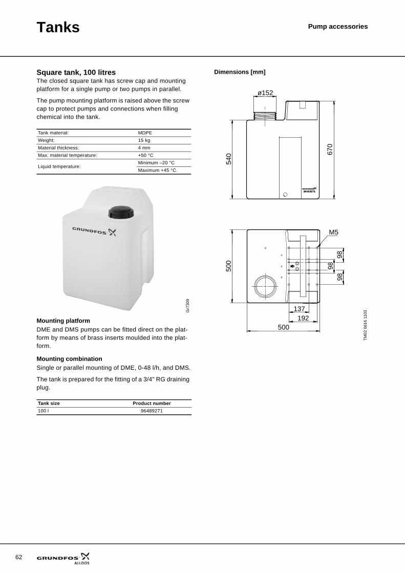
62
Pump accessoriesTanks
Square tank, 100 litresThe closed square tank has screw cap and mounting platform for a single pump or two pumps in parallel.
The pump mounting platform is raised above the screw cap to protect pumps and connections when filling chemical into the tank.
Mounting platformDME and DMS pumps can be fitted direct on the plat-form by means of brass inserts moulded into the plat-form.
Mounting combinationSingle or parallel mounting of DME, 0-48 l/h, and DMS.
The tank is prepared for the fitting of a 3/4" RG draining plug.
Dimensions [mm]
Tank material: MDPEWeight: 15 kgMaterial thickness: 4 mmMax. material temperature: +50 °C
Liquid temperature:Minimum –20 °CMaximum +45 °C.
Gr7
309
Tank size Product number100 l 96489271
TM02
661
6 11
03
ø152
500
500
540 67
098
9898
137192
M5
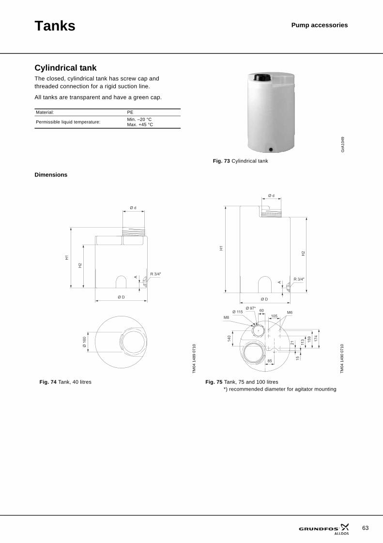
Tanks Pump accessories
Cylindrical tankThe closed, cylindrical tank has screw cap and threaded connection for a rigid suction line.
All tanks are transparent and have a green cap.
Dimensions
Material: PE
Permissible liquid temperature: Min. –20 °CMax. +45 °C
GrA
1049
Fig. 73 Cylindrical tank
TM04
148
9 07
10
TM04
149
0 07
10
Fig. 74 Tank, 40 litres Fig. 75 Tank, 75 and 100 litres*) recommended diameter for agitator mounting
Ø 1
60
Ø D
Ø d
R 3/4"
H2
H1
A
Ø D
R 3/4"
H2
H1
Ø d
A
2115
113 15
9
174
10560
85
140
M6M8
Ø 115Ø 97*
63
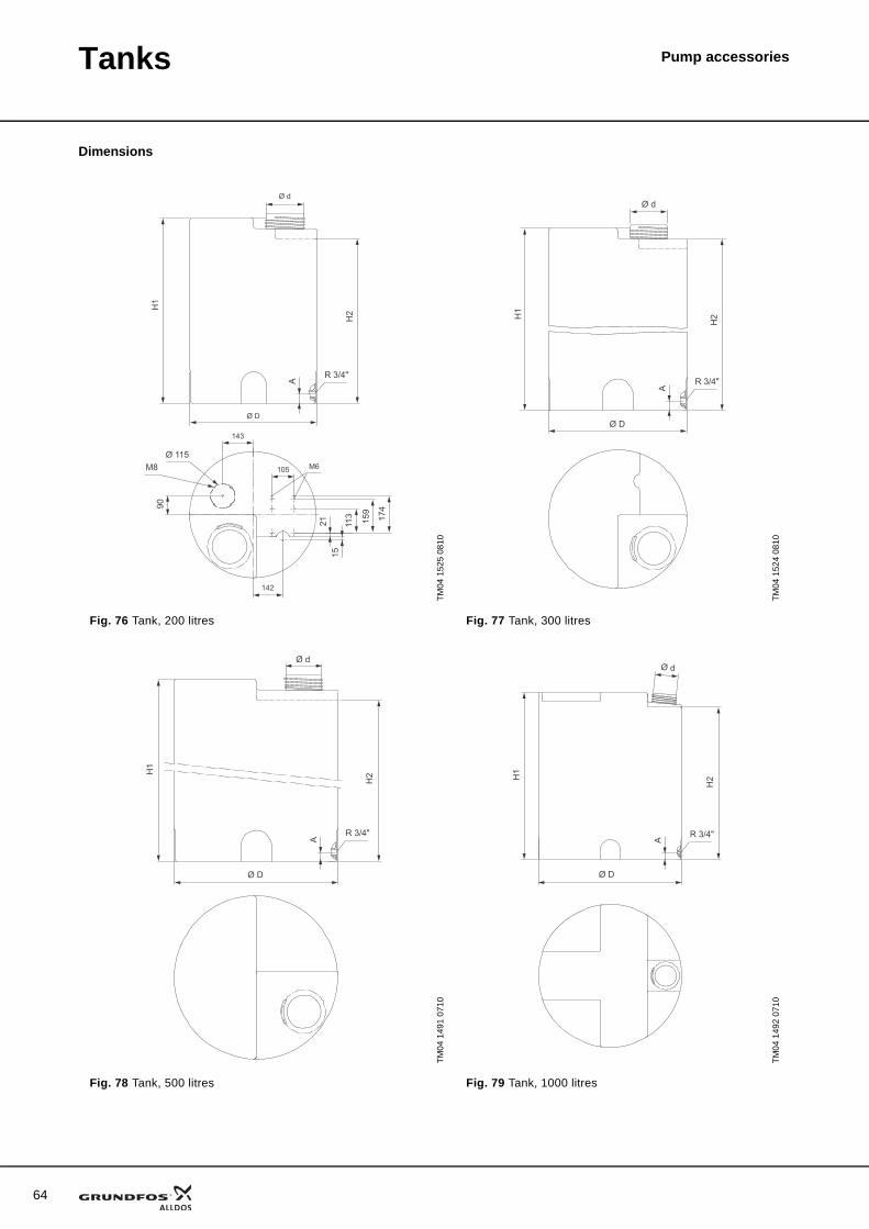
64
Tanks Pump accessories
Dimensions
TM04
152
5 08
10
TM04
152
4 08
10
Fig. 76 Tank, 200 litres Fig. 77 Tank, 300 litres
TM04
149
1 07
10
TM04
149
2 07
10
Fig. 78 Tank, 500 litres Fig. 79 Tank, 1000 litres
Ø D
Ø d
R 3/4"
A
H1
H2
90
143
105
142
113 159
174
2115
M6M8Ø 115
R 3/4"
A
Ø D
H2H
1
Ø d
A
R 3/4"
Ø D
H1
H2
Ø d
R 3/4"
Ø D
H1
Ø d
H2
A
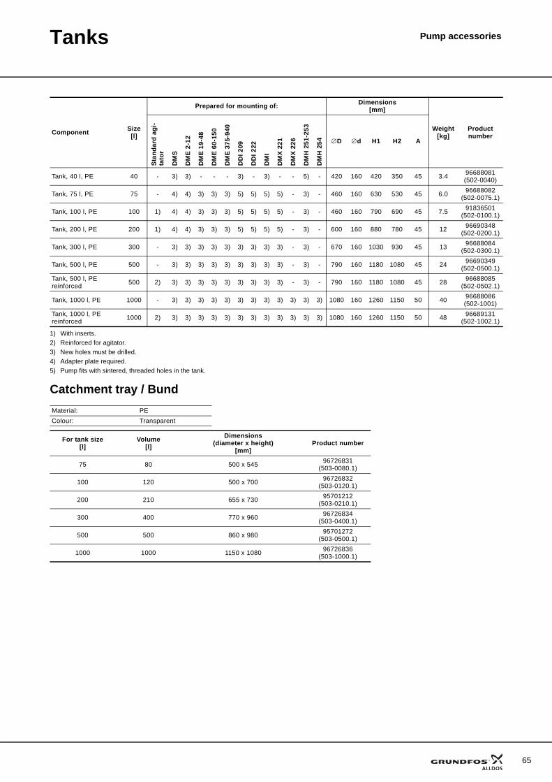
Tanks Pump accessories
1) With inserts.2) Reinforced for agitator.3) New holes must be drilled.4) Adapter plate required.5) Pump fits with sintered, threaded holes in the tank.
Catchment tray / Bund
Component Size[l]
Prepared for mounting of: Dimensions[mm]
Weight[kg]
Product number
Stan
dard
agi
-ta
tor
DM
S
DM
E 2-
12
DM
E 19
-48
DM
E 60
-150
DM
E 37
5-94
0
DD
I 209
DD
I 222
DM
I
DM
X 22
1
DM
X 22
6
DM
H 2
51-2
53
DM
H 2
54 ∅D ∅d H1 H2 A
Tank, 40 l, PE 40 - 3) 3) - - - 3) - 3) - - 5) - 420 160 420 350 45 3.4 96688081(502-0040)
Tank, 75 l, PE 75 - 4) 4) 3) 3) 3) 5) 5) 5) 5) - 3) - 460 160 630 530 45 6.0 96688082(502-0075.1)
Tank, 100 l, PE 100 1) 4) 4) 3) 3) 3) 5) 5) 5) 5) - 3) - 460 160 790 690 45 7.5 91836501(502-0100.1)
Tank, 200 l, PE 200 1) 4) 4) 3) 3) 3) 5) 5) 5) 5) - 3) - 600 160 880 780 45 12 96690348(502-0200.1)
Tank, 300 l, PE 300 - 3) 3) 3) 3) 3) 3) 3) 3) 3) - 3) - 670 160 1030 930 45 13 96688084(502-0300.1)
Tank, 500 l, PE 500 - 3) 3) 3) 3) 3) 3) 3) 3) 3) - 3) - 790 160 1180 1080 45 24 96690349(502-0500.1)
Tank, 500 l, PE reinforced 500 2) 3) 3) 3) 3) 3) 3) 3) 3) 3) - 3) - 790 160 1180 1080 45 28 96688085
(502-0502.1)
Tank, 1000 l, PE 1000 - 3) 3) 3) 3) 3) 3) 3) 3) 3) 3) 3) 3) 1080 160 1260 1150 50 40 96688086(502-1001)
Tank, 1000 l, PE reinforced 1000 2) 3) 3) 3) 3) 3) 3) 3) 3) 3) 3) 3) 3) 1080 160 1260 1150 50 48 96689131
(502-1002.1)
Material: PEColour: Transparent
For tank size[l]
Volume[l]
Dimensions(diameter x height)
[mm]Product number
75 80 500 x 545 96726831(503-0080.1)
100 120 500 x 700 96726832(503-0120.1)
200 210 655 x 730 95701212(503-0210.1)
300 400 770 x 960 96726834(503-0400.1)
500 500 860 x 980 95701272(503-0500.1)
1000 1000 1150 x 1080 96726836(503-1000.1)
65
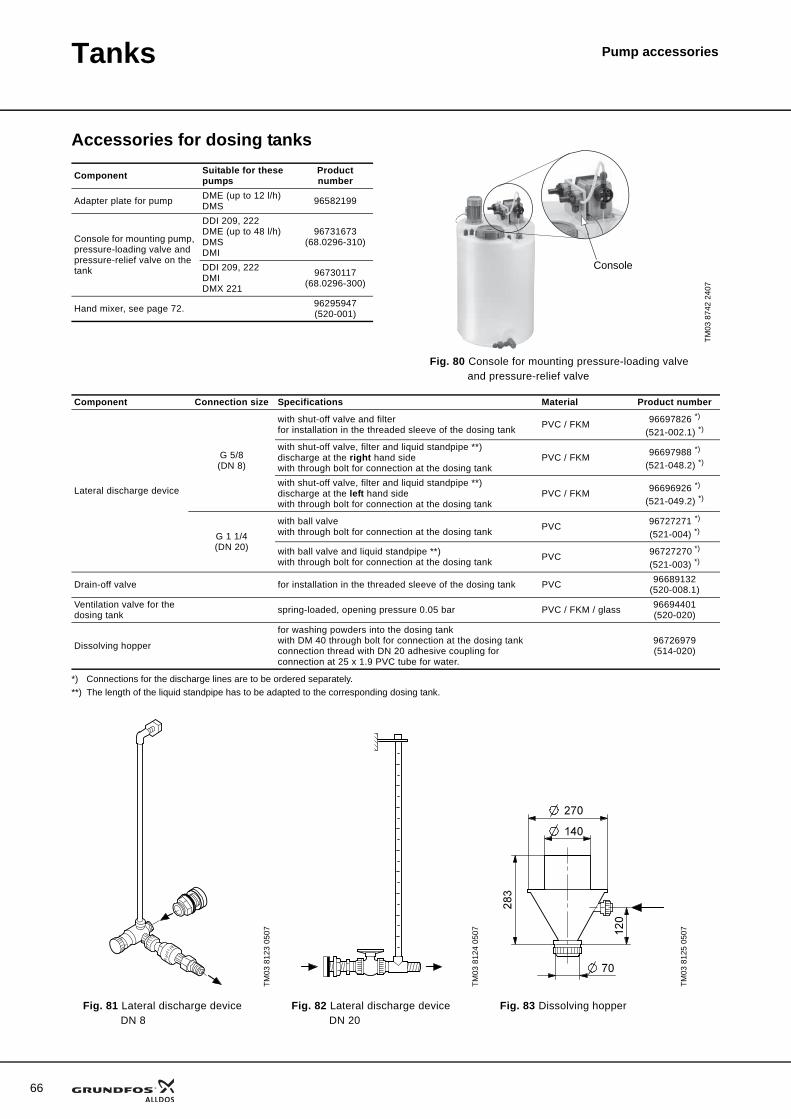
66
Tanks Pump accessories
Accessories for dosing tanks
*) Connections for the discharge lines are to be ordered separately.**) The length of the liquid standpipe has to be adapted to the corresponding dosing tank.
Component Suitable for these pumps
Product number
Adapter plate for pump DME (up to 12 l/h)DMS 96582199
Console for mounting pump, pressure-loading valve and pressure-relief valve on the tank
DDI 209, 222DME (up to 48 l/h)DMSDMI
96731673(68.0296-310)
DDI 209, 222DMIDMX 221
96730117(68.0296-300)
Hand mixer, see page 72. 96295947(520-001)
TM03
874
2 24
07
Fig. 80 Console for mounting pressure-loading valve and pressure-relief valve
Console
Component Connection size Specifications Material Product number
Lateral discharge device
G 5/8(DN 8)
with shut-off valve and filterfor installation in the threaded sleeve of the dosing tank PVC / FKM 96697826 *)
(521-002.1) *)
with shut-off valve, filter and liquid standpipe **)discharge at the right hand sidewith through bolt for connection at the dosing tank
PVC / FKM 96697988 *)
(521-048.2) *)
with shut-off valve, filter and liquid standpipe **)discharge at the left hand sidewith through bolt for connection at the dosing tank
PVC / FKM 96696926 *)
(521-049.2) *)
G 1 1/4(DN 20)
with ball valvewith through bolt for connection at the dosing tank PVC 96727271 *)
(521-004) *)
with ball valve and liquid standpipe **)with through bolt for connection at the dosing tank PVC 96727270 *)
(521-003) *)
Drain-off valve for installation in the threaded sleeve of the dosing tank PVC 96689132(520-008.1)
Ventilation valve for the dosing tank spring-loaded, opening pressure 0.05 bar PVC / FKM / glass 96694401
(520-020)
Dissolving hopper
for washing powders into the dosing tankwith DM 40 through bolt for connection at the dosing tankconnection thread with DN 20 adhesive coupling for connection at 25 x 1.9 PVC tube for water.
96726979(514-020)
TM03
812
3 05
07
TM03
812
4 05
07
TM03
812
5 05
07
Fig. 81 Lateral discharge device DN 8
Fig. 82 Lateral discharge device DN 20
Fig. 83 Dissolving hopper
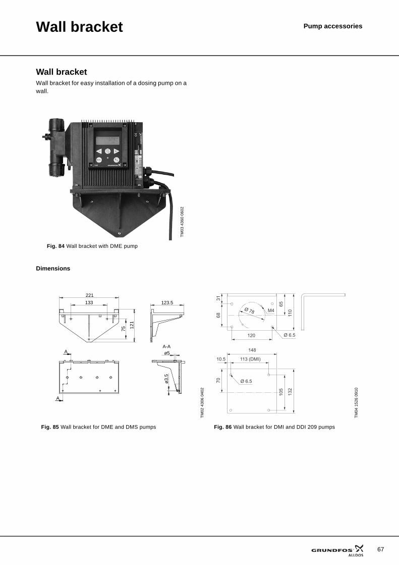
Pump accessoriesWall bracket
Wall bracketWall bracket for easy installation of a dosing pump on a wall.
Dimensions
TM03
436
0 06
02
Fig. 84 Wall bracket with DME pump
TM02
430
6 04
02
TM04
152
6 09
10
Fig. 85 Wall bracket for DME and DMS pumps Fig. 86 Wall bracket for DMI and DDI 209 pumps
221
133
75 121
123.5
A-Aø5
ø3.
5
A
A 148
113 (DMI)
120
105
132
10.5
70
65
110
6831
Ø 6.5
Ø 6.5
Ø 78 M4
67
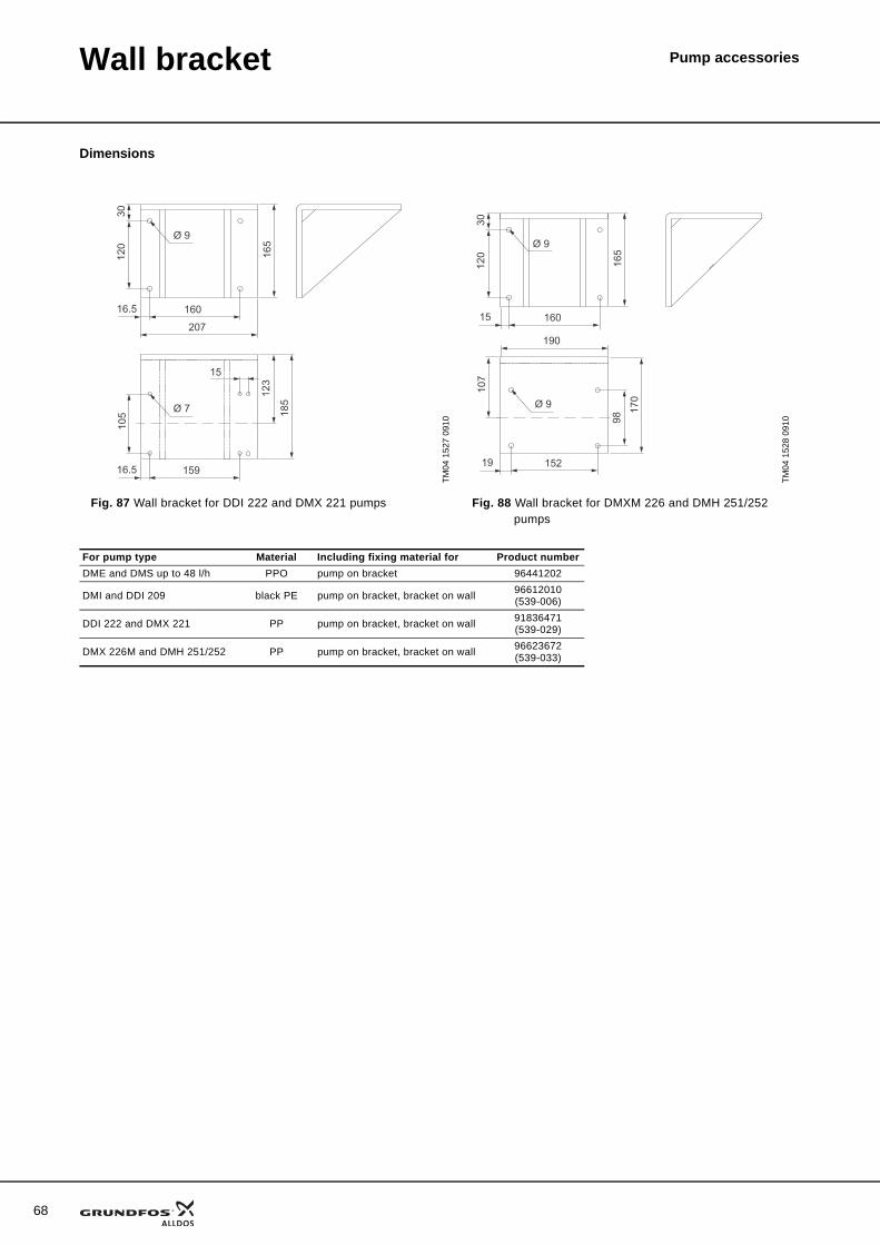
68
Wall bracket Pump accessories
Dimensions
TM04
152
7 09
10
TM04
152
8 09
10
Fig. 87 Wall bracket for DDI 222 and DMX 221 pumps Fig. 88 Wall bracket for DMXM 226 and DMH 251/252 pumps
120
30
160
105
16.5
207
15916.5
15
165
123
185Ø 7
Ø 9
120
30
160
107
15
190
15219
165
98
170
Ø 9
Ø 9
For pump type Material Including fixing material for Product numberDME and DMS up to 48 l/h PPO pump on bracket 96441202
DMI and DDI 209 black PE pump on bracket, bracket on wall 96612010 (539-006)
DDI 222 and DMX 221 PP pump on bracket, bracket on wall 91836471 (539-029)
DMX 226M and DMH 251/252 PP pump on bracket, bracket on wall 96623672 (539-033)
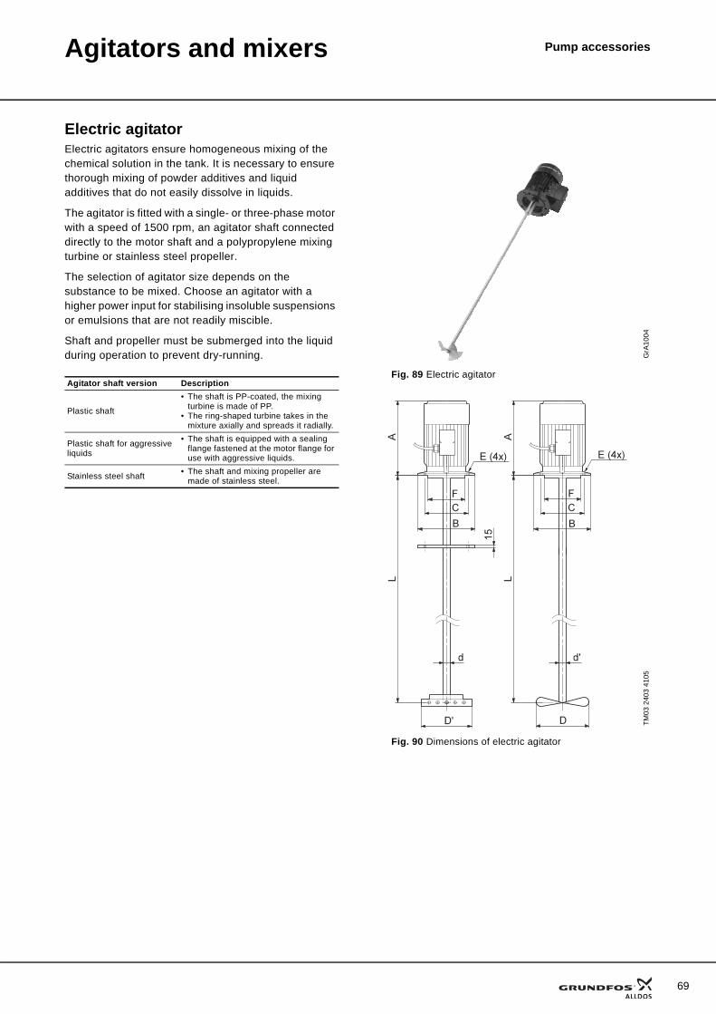
Pump accessoriesAgitators and mixers
Electric agitatorElectric agitators ensure homogeneous mixing of the chemical solution in the tank. It is necessary to ensure thorough mixing of powder additives and liquid additives that do not easily dissolve in liquids.
The agitator is fitted with a single- or three-phase motor with a speed of 1500 rpm, an agitator shaft connected directly to the motor shaft and a polypropylene mixing turbine or stainless steel propeller.
The selection of agitator size depends on the substance to be mixed. Choose an agitator with a higher power input for stabilising insoluble suspensions or emulsions that are not readily miscible.
Shaft and propeller must be submerged into the liquid during operation to prevent dry-running.
Agitator shaft version Description
Plastic shaft
• The shaft is PP-coated, the mixing turbine is made of PP.
• The ring-shaped turbine takes in the mixture axially and spreads it radially.
Plastic shaft for aggressive liquids
• The shaft is equipped with a sealing flange fastened at the motor flange for use with aggressive liquids.
Stainless steel shaft • The shaft and mixing propeller are made of stainless steel.
GrA
1004
Fig. 89 Electric agitator
TM03
240
3 41
05
Fig. 90 Dimensions of electric agitator
69
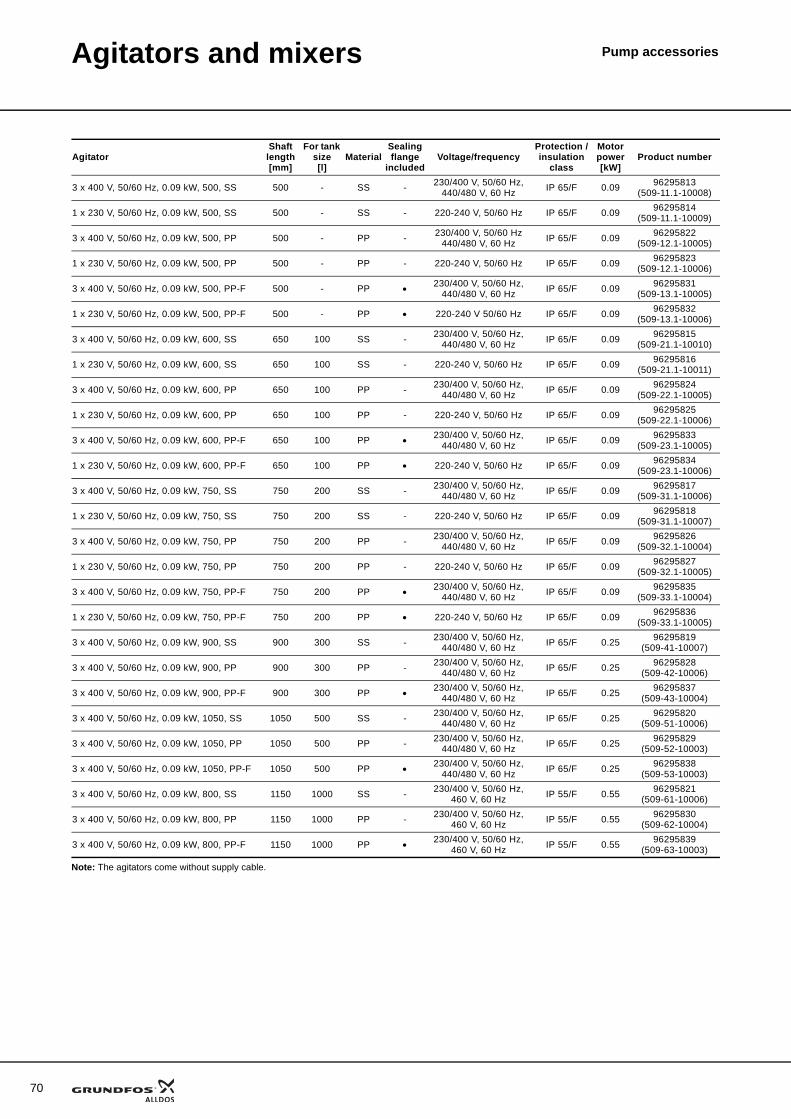
70
Agitators and mixers Pump accessories
Note: The agitators come without supply cable.
AgitatorShaft length[mm]
For tank size[l]
MaterialSealing flange
includedVoltage/frequency
Protection / insulation
class
Motor power[kW]
Product number
3 x 400 V, 50/60 Hz, 0.09 kW, 500, SS 500 - SS - 230/400 V, 50/60 Hz, 440/480 V, 60 Hz IP 65/F 0.09 96295813
(509-11.1-10008)
1 x 230 V, 50/60 Hz, 0.09 kW, 500, SS 500 - SS - 220-240 V, 50/60 Hz IP 65/F 0.09 96295814(509-11.1-10009)
3 x 400 V, 50/60 Hz, 0.09 kW, 500, PP 500 - PP - 230/400 V, 50/60 Hz 440/480 V, 60 Hz IP 65/F 0.09 96295822
(509-12.1-10005)
1 x 230 V, 50/60 Hz, 0.09 kW, 500, PP 500 - PP - 220-240 V, 50/60 Hz IP 65/F 0.09 96295823(509-12.1-10006)
3 x 400 V, 50/60 Hz, 0.09 kW, 500, PP-F 500 - PP • 230/400 V, 50/60 Hz, 440/480 V, 60 Hz IP 65/F 0.09 96295831
(509-13.1-10005)
1 x 230 V, 50/60 Hz, 0.09 kW, 500, PP-F 500 - PP • 220-240 V 50/60 Hz IP 65/F 0.09 96295832(509-13.1-10006)
3 x 400 V, 50/60 Hz, 0.09 kW, 600, SS 650 100 SS - 230/400 V, 50/60 Hz, 440/480 V, 60 Hz IP 65/F 0.09 96295815
(509-21.1-10010)
1 x 230 V, 50/60 Hz, 0.09 kW, 600, SS 650 100 SS - 220-240 V, 50/60 Hz IP 65/F 0.09 96295816(509-21.1-10011)
3 x 400 V, 50/60 Hz, 0.09 kW, 600, PP 650 100 PP - 230/400 V, 50/60 Hz, 440/480 V, 60 Hz IP 65/F 0.09 96295824
(509-22.1-10005)
1 x 230 V, 50/60 Hz, 0.09 kW, 600, PP 650 100 PP - 220-240 V, 50/60 Hz IP 65/F 0.09 96295825(509-22.1-10006)
3 x 400 V, 50/60 Hz, 0.09 kW, 600, PP-F 650 100 PP • 230/400 V, 50/60 Hz, 440/480 V, 60 Hz IP 65/F 0.09 96295833
(509-23.1-10005)
1 x 230 V, 50/60 Hz, 0.09 kW, 600, PP-F 650 100 PP • 220-240 V, 50/60 Hz IP 65/F 0.09 96295834(509-23.1-10006)
3 x 400 V, 50/60 Hz, 0.09 kW, 750, SS 750 200 SS - 230/400 V, 50/60 Hz, 440/480 V, 60 Hz IP 65/F 0.09 96295817
(509-31.1-10006)
1 x 230 V, 50/60 Hz, 0.09 kW, 750, SS 750 200 SS - 220-240 V, 50/60 Hz IP 65/F 0.09 96295818(509-31.1-10007)
3 x 400 V, 50/60 Hz, 0.09 kW, 750, PP 750 200 PP - 230/400 V, 50/60 Hz, 440/480 V, 60 Hz IP 65/F 0.09 96295826
(509-32.1-10004)
1 x 230 V, 50/60 Hz, 0.09 kW, 750, PP 750 200 PP - 220-240 V, 50/60 Hz IP 65/F 0.09 96295827(509-32.1-10005)
3 x 400 V, 50/60 Hz, 0.09 kW, 750, PP-F 750 200 PP • 230/400 V, 50/60 Hz, 440/480 V, 60 Hz IP 65/F 0.09 96295835
(509-33.1-10004)
1 x 230 V, 50/60 Hz, 0.09 kW, 750, PP-F 750 200 PP • 220-240 V, 50/60 Hz IP 65/F 0.09 96295836(509-33.1-10005)
3 x 400 V, 50/60 Hz, 0.09 kW, 900, SS 900 300 SS - 230/400 V, 50/60 Hz, 440/480 V, 60 Hz IP 65/F 0.25 96295819
(509-41-10007)
3 x 400 V, 50/60 Hz, 0.09 kW, 900, PP 900 300 PP - 230/400 V, 50/60 Hz, 440/480 V, 60 Hz IP 65/F 0.25 96295828
(509-42-10006)
3 x 400 V, 50/60 Hz, 0.09 kW, 900, PP-F 900 300 PP • 230/400 V, 50/60 Hz, 440/480 V, 60 Hz IP 65/F 0.25 96295837
(509-43-10004)
3 x 400 V, 50/60 Hz, 0.09 kW, 1050, SS 1050 500 SS - 230/400 V, 50/60 Hz, 440/480 V, 60 Hz IP 65/F 0.25 96295820
(509-51-10006)
3 x 400 V, 50/60 Hz, 0.09 kW, 1050, PP 1050 500 PP - 230/400 V, 50/60 Hz, 440/480 V, 60 Hz IP 65/F 0.25 96295829
(509-52-10003)
3 x 400 V, 50/60 Hz, 0.09 kW, 1050, PP-F 1050 500 PP • 230/400 V, 50/60 Hz, 440/480 V, 60 Hz IP 65/F 0.25 96295838
(509-53-10003)
3 x 400 V, 50/60 Hz, 0.09 kW, 800, SS 1150 1000 SS - 230/400 V, 50/60 Hz, 460 V, 60 Hz IP 55/F 0.55 96295821
(509-61-10006)
3 x 400 V, 50/60 Hz, 0.09 kW, 800, PP 1150 1000 PP - 230/400 V, 50/60 Hz, 460 V, 60 Hz IP 55/F 0.55 96295830
(509-62-10004)
3 x 400 V, 50/60 Hz, 0.09 kW, 800, PP-F 1150 1000 PP • 230/400 V, 50/60 Hz, 460 V, 60 Hz IP 55/F 0.55 96295839
(509-63-10003)
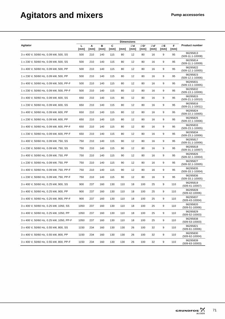
Agitators and mixers Pump accessories
AgitatorDimensions
Product numberL[mm]
A[mm]
B[mm]
C[mm] [mm]
∅d[mm]
∅D'[mm]
∅d'[mm]
∅E[mm]
F[mm]
3 x 400 V, 50/60 Hz, 0.09 kW, 500, SS 500 210 140 115 80 12 80 16 9 95 96295813(509-11.1-10008)
1 x 230 V, 50/60 Hz, 0.09 kW, 500, SS 500 210 140 115 80 12 80 16 9 95 96295814(509-11.1-10009)
3 x 400 V, 50/60 Hz, 0.09 kW, 500, PP 500 210 140 115 80 12 80 16 9 95 96295822(509-12.1-10005)
1 x 230 V, 50/60 Hz, 0.09 kW, 500, PP 500 210 140 115 80 12 80 16 9 95 96295823(509-12.1-10006)
3 x 400 V, 50/60 Hz, 0.09 kW, 500, PP-F 500 210 140 115 80 12 80 16 9 95 96295831(509-13.1-10005)
1 x 230 V, 50/60 Hz, 0.09 kW, 500, PP-F 500 210 140 115 80 12 80 16 9 95 96295832(509-13.1-10006)
3 x 400 V, 50/60 Hz, 0.09 kW, 600, SS 650 210 140 115 80 12 80 16 9 95 96295815(509-21.1-10010)
1 x 230 V, 50/60 Hz, 0.09 kW, 600, SS 650 210 140 115 80 12 80 16 9 95 96295816(509-21.1-10011)
3 x 400 V, 50/60 Hz, 0.09 kW, 600, PP 650 210 140 115 80 12 80 16 9 95 96295824(509-22.1-10005)
1 x 230 V, 50/60 Hz, 0.09 kW, 600, PP 650 210 140 115 80 12 80 16 9 95 96295825(509-22.1-10006)
3 x 400 V, 50/60 Hz, 0.09 kW, 600, PP-F 650 210 140 115 80 12 80 16 9 95 96295833(509-23.1-10005)
1 x 230 V, 50/60 Hz, 0.09 kW, 600, PP-F 650 210 140 115 80 12 80 16 9 95 96295834(509-23.1-10006)
3 x 400 V, 50/60 Hz, 0.09 kW, 750, SS 750 210 140 115 90 12 80 16 9 95 96295817(509-31.1-10006)
1 x 230 V, 50/60 Hz, 0.09 kW, 750, SS 750 210 140 115 90 12 80 16 9 95 96295818(509-31.1-10007)
3 x 400 V, 50/60 Hz, 0.09 kW, 750, PP 750 210 140 115 90 12 80 16 9 95 96295826(509-32.1-10004)
1 x 230 V, 50/60 Hz, 0.09 kW, 750, PP 750 210 140 115 90 12 80 16 9 95 96295827(509-32.1-10005)
3 x 400 V, 50/60 Hz, 0.09 kW, 750, PP-F 750 210 140 115 90 12 80 16 9 95 96295835(509-33.1-10004)
1 x 230 V, 50/60 Hz, 0.09 kW, 750, PP-F 750 210 140 115 90 12 80 16 9 95 96295836(509-33.1-10005)
3 x 400 V, 50/60 Hz, 0.25 kW, 900, SS 900 237 160 130 110 18 100 25 9 110 96295819(509-41-10007)
3 x 400 V, 50/60 Hz, 0.25 kW, 900, PP 900 237 160 130 110 18 100 25 9 110 96295828(509-42-10006)
3 x 400 V, 50/60 Hz, 0.25 kW, 900, PP-F 900 237 160 130 110 18 100 25 9 110 96295837(509-43-10004)
3 x 400 V, 50/60 Hz, 0.25 kW, 1050, SS 1050 237 160 130 110 18 100 25 9 110 96295820(509-51-10006)
3 x 400 V, 50/60 Hz, 0.25 kW, 1050, PP 1050 237 160 130 110 18 100 25 9 110 96295829(509-52-10003)
3 x 400 V, 50/60 Hz, 0.25 kW, 1050, PP-F 1050 237 160 130 110 18 100 25 9 110 96295838(509-53-10003)
3 x 400 V, 50/60 Hz, 0.55 kW, 800, SS 1150 234 160 130 130 26 100 32 9 110 96295821(509-61-10006)
3 x 400 V, 50/60 Hz, 0.55 kW, 800, PP 1150 234 160 130 130 26 100 32 9 110 96295830(509-62-10004)
3 x 400 V, 50/60 Hz, 0.55 kW, 800, PP-F 1150 234 160 130 130 26 100 32 9 110 96295839(509-63-10003)
71

72
Agitators and mixers Pump accessories
Hand mixerHand mixer with adjustable length for mixing of chemi-cals in a tank. The mixer is designed for Grundfos All-dos chemical tanks, sizes 40 - 500 litres.
The length is adapted to the corresponding tank before delivery. In case of separate delivery, the hand knob is not glued on.
Dimensions
TM03
241
0 41
05
Fig. 91 Dimension of hand mixer
Shaft lengthL
[mm]Material Product number
1200 PVC 96295947(520-001)
TM03
789
1 51
06
Fig. 92 Hand mixer
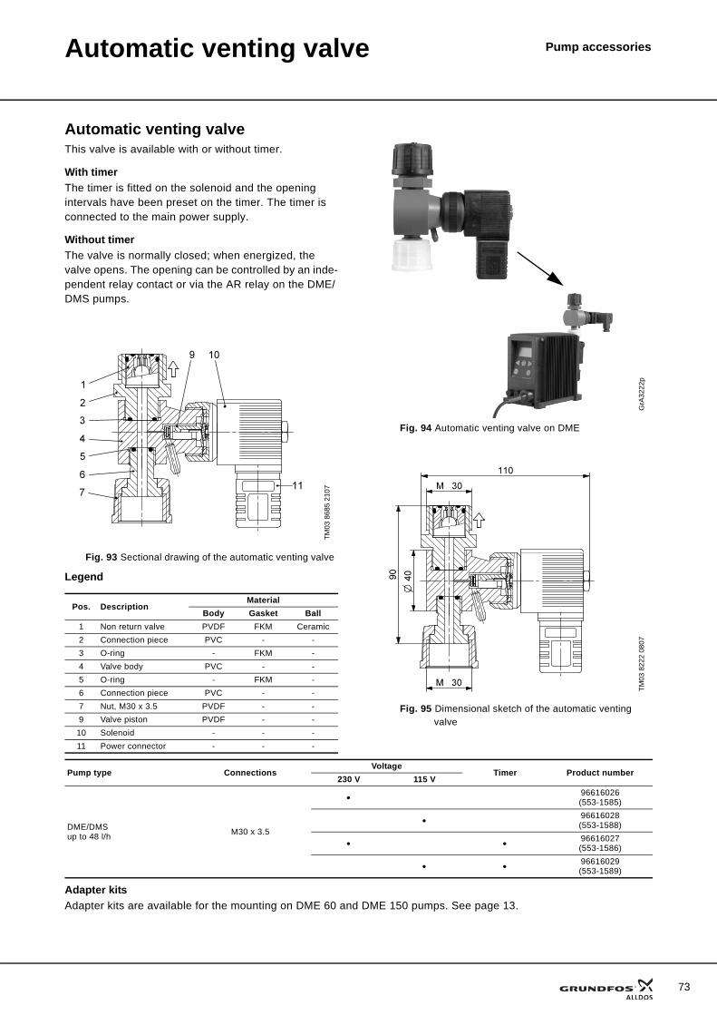
73
Pump accessoriesAutomatic venting valve
Automatic venting valveThis valve is available with or without timer.
With timerThe timer is fitted on the solenoid and the opening intervals have been preset on the timer. The timer is connected to the main power supply.
Without timerThe valve is normally closed; when energized, the valve opens. The opening can be controlled by an inde-pendent relay contact or via the AR relay on the DME/DMS pumps.
Legend
Adapter kitsAdapter kits are available for the mounting on DME 60 and DME 150 pumps. See page 13.
TM03
868
5 21
07
Fig. 93 Sectional drawing of the automatic venting valve
Pos. DescriptionMaterial
Body Gasket Ball1 Non return valve PVDF FKM Ceramic2 Connection piece PVC - -3 O-ring - FKM -4 Valve body PVC - -5 O-ring - FKM -6 Connection piece PVC - -7 Nut, M30 x 3.5 PVDF - -9 Valve piston PVDF - -
10 Solenoid - - -11 Power connector - - -
GrA
3222
p
Fig. 94 Automatic venting valve on DME
TM03
822
2 08
07
Fig. 95 Dimensional sketch of the automatic venting valve
Pump type ConnectionsVoltage
Timer Product number230 V 115 V
DME/DMSup to 48 l/h M30 x 3.5
• 96616026(553-1585)
• 96616028(553-1588)
• • 96616027(553-1586)
• • 96616029(553-1589)
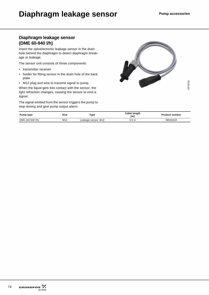
Pump accessories
74
Diaphragm leakage sensor
Diaphragm leakage sensor (DME 60-940 l/h)Insert the optoelectronic leakage sensor in the drain hole behind the diaphragm to detect diaphragm break-age or leakage.
The sensor unit consists of these components:
• transmitter receiver• holder for fitting sensor in the drain hole of the back
plate• M12 plug and wire to transmit signal to pump.When the liquid gets into contact with the sensor, the light refraction changes, causing the sensor to emit a signal.
The signal emitted from the sensor triggers the pump to stop dosing and give pump output alarm.
GR
821
1p
Pump type Size Type Cable length[m] Product number
DME (60-940 l/h) M12 Leakage sensor, M12 0.5 m 96534443
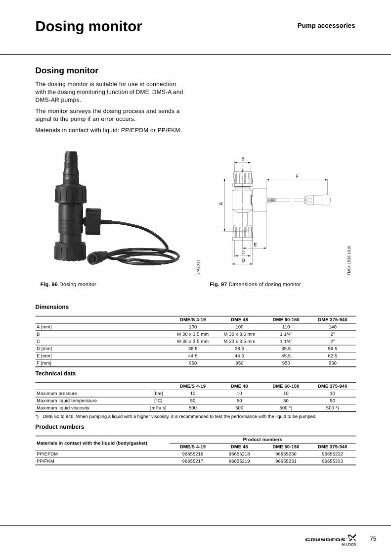
75
Pump accessoriesDosing monitor
Dosing monitorThe dosing monitor is suitable for use in connection with the dosing monitoring function of DME, DMS-A and DMS-AR pumps.
The monitor surveys the dosing process and sends a signal to the pump if an error occurs.
Materials in contact with liquid: PP/EPDM or PP/FKM.
Dimensions
Technical data
*) DME 60 to 940: When pumping a liquid with a higher viscosity, it is recommended to test the performance with the liquid to be pumped.
Product numbers
GrA
1033
TM04
153
6 10
10
Fig. 96 Dosing monitor Fig. 97 Dimensions of dosing monitor
F
B
E
C
D
A
DME/S 4-19 DME 48 DME 60-150 DME 375-940A [mm] 100 100 110 140B M 30 x 3.5 mm M 30 x 3.5 mm 1 1/4” 2”C M 30 x 3.5 mm M 30 x 3.5 mm 1 1/4” 2”D [mm] 38.5 38.5 39.5 56.5E [mm] 44.5 44.5 45.5 62.5F [mm] 950 950 950 950
DME/S 4-19 DME 48 DME 60-150 DME 375-940Maximum pressure [bar] 10 10 10 10Maximum liquid temperature [°C] 50 50 50 50Maximum liquid viscosity [mPa s] 500 500 500 *) 500 *)
Materials in contact with the liquid (body/gasket)Product numbers
DME/S 4-19 DME 48 DME 60-150 DME 375-940PP/EPDM 96655216 96655218 96655230 96655232PP/FKM 96655217 96655219 96655231 96655233
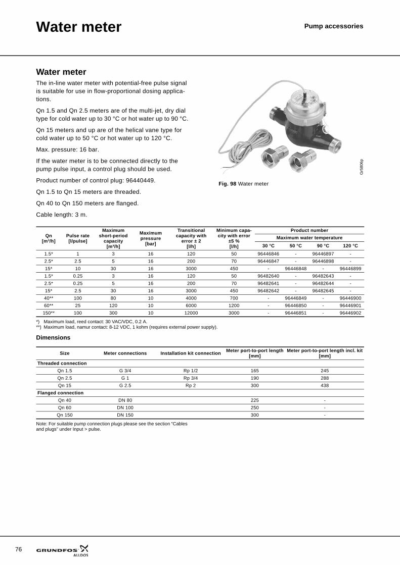
Pump accessories
76
Water meter
Water meterThe in-line water meter with potential-free pulse signal is suitable for use in flow-proportional dosing applica-tions.
Qn 1.5 and Qn 2.5 meters are of the multi-jet, dry dial type for cold water up to 30 °C or hot water up to 90 °C.
Qn 15 meters and up are of the helical vane type for cold water up to 50 °C or hot water up to 120 °C.
Max. pressure: 16 bar.
If the water meter is to be connected directly to the pump pulse input, a control plug should be used.
Product number of control plug: 96440449.
Qn 1.5 to Qn 15 meters are threaded.
Qn 40 to Qn 150 meters are flanged.
Cable length: 3 m.
*) Maximum load, reed contact: 30 VAC/VDC, 0.2 A.**) Maximum load, namur contact: 8-12 VDC, 1 kohm (requires external power supply).
Dimensions
Note: For suitable pump connection plugs please see the section “Cables and plugs” under Input > pulse.
Gr5
806p
Fig. 98 Water meter
Qn[m³/h]
Pulse rate[l/pulse]
Maximum short-period
capacity[m³/h]
Maximum pressure
[bar]
Transitional capacity with
error ± 2 [l/h]
Minimum capa-city with error
±5 %[l/h]
Product numberMaximum water temperature
30 °C 50 °C 90 °C 120 °C1.5* 1 3 16 120 50 96446846 - 96446897 -2.5* 2.5 5 16 200 70 96446847 - 96446898 -15* 10 30 16 3000 450 - 96446848 - 964468991.5* 0.25 3 16 120 50 96482640 - 96482643 -2.5* 0.25 5 16 200 70 96482641 - 96482644 -15* 2.5 30 16 3000 450 96482642 - 96482645 -40** 100 80 10 4000 700 - 96446849 - 9644690060** 25 120 10 6000 1200 - 96446850 - 96446901
150** 100 300 10 12000 3000 - 96446851 - 96446902
Size Meter connections Installation kit connection Meter port-to-port length[mm]
Meter port-to-port length incl. kit[mm]
Threaded connectionQn 1.5 G 3/4 Rp 1/2 165 245Qn 2.5 G 1 Rp 3/4 190 288Qn 15 G 2.5 Rp 2 300 438
Flanged connectionQn 40 DN 80 225 -Qn 60 DN 100 250 -
Qn 150 DN 150 300 -
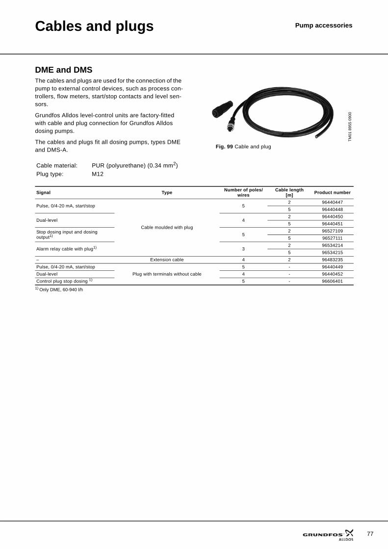
Pump accessoriesCables and plugs
DME and DMSThe cables and plugs are used for the connection of the pump to external control devices, such as process con-trollers, flow meters, start/stop contacts and level sen-sors.
Grundfos Alldos level-control units are factory-fitted with cable and plug connection for Grundfos Alldos dosing pumps.
The cables and plugs fit all dosing pumps, types DME and DMS-A.
Cable material: PUR (polyurethane) (0.34 mm2)Plug type: M12
TM01
895
5 09
00
Fig. 99 Cable and plug
Signal Type Number of poles/wires
Cable length[m] Product number
Pulse, 0/4-20 mA, start/stop
Cable moulded with plug
52 964404475 96440448
Dual-level 42 964404505 96440451
Stop dosing input and dosing output1) 5
2 965271095 96527111
Alarm relay cable with plug1) 32 965342145 96534215
– Extension cable 4 2 96483235Pulse, 0/4-20 mA, start/stop
Plug with terminals without cable5 - 96440449
Dual-level 4 - 96440452Control plug stop dosing 1) 5 - 96606401
1) Only DME, 60-940 l/h
77
78
Cables and plugs Pump accessories
DMI, DMX, DMH and DDI
ApplicationPlug Cable
Product numberType Number of
pins Coding Straight / angled
Length[m] Other
Input Analog pulse remote switch Plug connector 4 A
Straight
2 96609014(321-205)
5 96609016(321-207)
Plug only 96698715(321-325)
Angled 2 96693246(321-204)
Output Error relay (stroke or pre-empty relay) Pug connector 4 B
Straight
2 96609017(321-206)
5 96609019(321-208)
Plug only 96696198(321-227)
Angled 2 96698716(321-286)
Output Analog Plug connector 5 AStraight
2 96632921(321-215)
5 96632922(321-216)
Plug only 96609031(321-217)
Angled 2 96699697(321-271)
Combined Flow Monitor INanalog OUT
Pre-assembled: plug connector with 2 m of analog out cable
5 A Straight 2 96645265(321-327)
Input (Pre-)empty Plug connector 4 A Straight - 96698715(321-325)
Input Empty Flat plug connector 2 Square type Straight - Cable soldered
96679388(10.2604-203)
Input (Pre-)empty Flat plug connector 3 Square type Straight - Cable soldered
96630345(10.2604-204)
Adapter flat-round (Pre-)empty Plug connector 4 A Straight - 96635010(321-326)
Profibus Y-connector - 96693735(321-225)
Profibus Terminating resistor - 96693737(321-224)
Mains (222) 110-240 VAC Solenoid valve connector 3 DIN 43650 angled - 96698717
(45.10084-1)
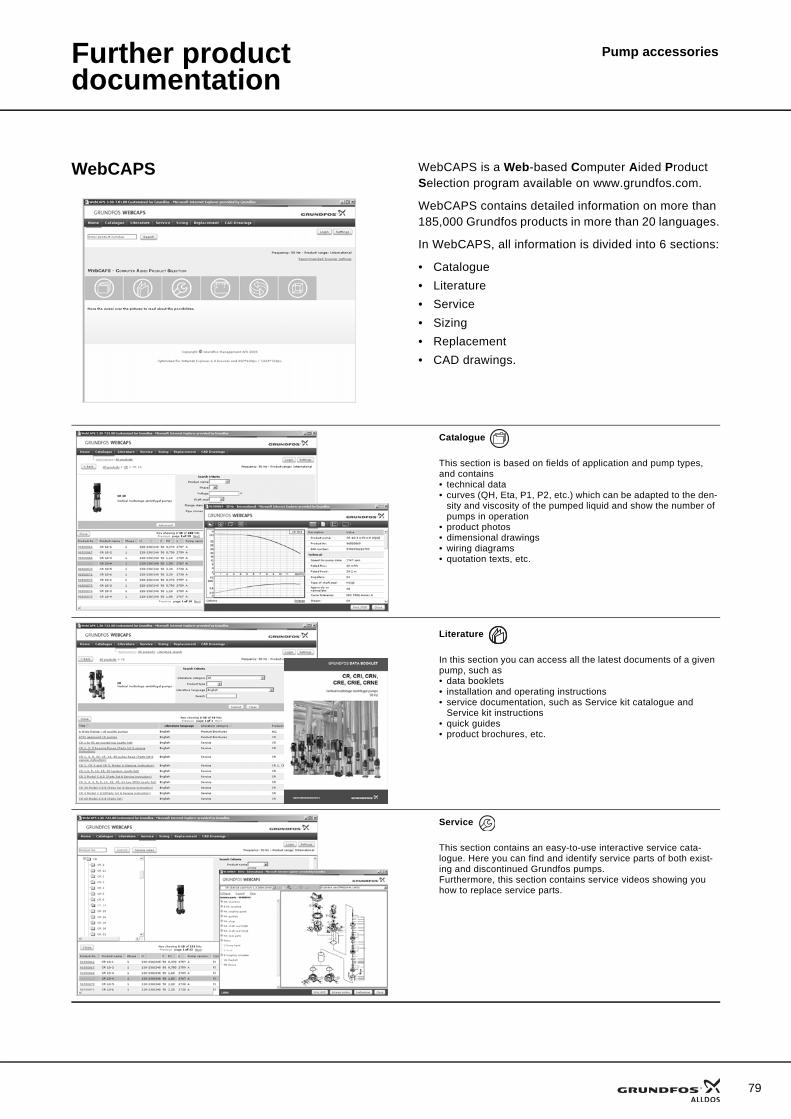
Pump accessoriesFurther product documentation
WebCAPS WebCAPS is a Web-based Computer Aided Product Selection program available on www.grundfos.com.
WebCAPS contains detailed information on more than 185,000 Grundfos products in more than 20 languages.
In WebCAPS, all information is divided into 6 sections:
• Catalogue• Literature• Service• Sizing• Replacement• CAD drawings.
Catalogue
This section is based on fields of application and pump types, and contains • technical data• curves (QH, Eta, P1, P2, etc.) which can be adapted to the den-
sity and viscosity of the pumped liquid and show the number of pumps in operation
• product photos• dimensional drawings• wiring diagrams• quotation texts, etc.
Literature
In this section you can access all the latest documents of a given pump, such as• data booklets• installation and operating instructions• service documentation, such as Service kit catalogue and
Service kit instructions• quick guides• product brochures, etc.
Service
This section contains an easy-to-use interactive service cata-logue. Here you can find and identify service parts of both exist-ing and discontinued Grundfos pumps.Furthermore, this section contains service videos showing you how to replace service parts.
79
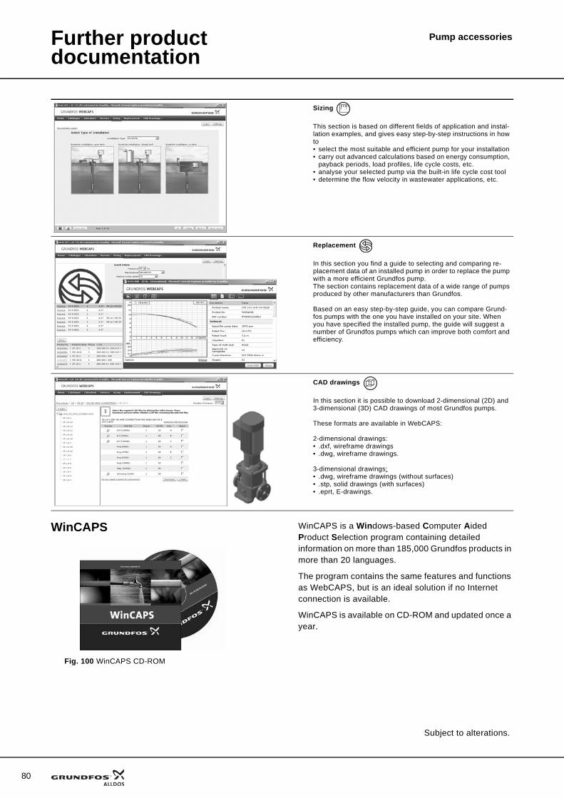
80
Further product documentation
Pump accessories
WinCAPS
Fig. 100 WinCAPS CD-ROM
WinCAPS is a Windows-based Computer Aided Product Selection program containing detailed information on more than 185,000 Grundfos products in more than 20 languages.
The program contains the same features and functions as WebCAPS, but is an ideal solution if no Internet connection is available.
WinCAPS is available on CD-ROM and updated once a year.
Sizing
This section is based on different fields of application and instal-lation examples, and gives easy step-by-step instructions in how to• select the most suitable and efficient pump for your installation• carry out advanced calculations based on energy consumption,
payback periods, load profiles, life cycle costs, etc.• analyse your selected pump via the built-in life cycle cost tool• determine the flow velocity in wastewater applications, etc.
Replacement
In this section you find a guide to selecting and comparing re-placement data of an installed pump in order to replace the pump with a more efficient Grundfos pump. The section contains replacement data of a wide range of pumps produced by other manufacturers than Grundfos.
Based on an easy step-by-step guide, you can compare Grund-fos pumps with the one you have installed on your site. When you have specified the installed pump, the guide will suggest a number of Grundfos pumps which can improve both comfort and efficiency.
CAD drawings
In this section it is possible to download 2-dimensional (2D) and 3-dimensional (3D) CAD drawings of most Grundfos pumps.
These formats are available in WebCAPS:
2-dimensional drawings:• .dxf, wireframe drawings• .dwg, wireframe drawings.
3-dimensional drawings:• .dwg, wireframe drawings (without surfaces)• .stp, solid drawings (with surfaces)• .eprt, E-drawings.
0 1
Subject to alterations.

81

82

83
www.grundfosalldos.com
Grundfos Management A/SPoul Due Jensens Vej 7DK-8850 Bjerringbro
Telephone: +45 87 50 14 00
Grundfos Alldos Dosing & Disinfection Alldos Eichler GmbHReetzstrasse 85D-76327 Pfinztal (Söllingen)
Telephone: +49 72 40 61 0
96700284 0410 GBRepl. 96700284 0907
Being responsible is our foundationThinking ahead makes it possible
Innovation is the essence
The name Grundfos, the Grundfos logo, and the payoff Be–Think–Innovate are registrated trademarks owned by Grundfos Management A/S or Grundfos A/S, Denmark. All rights reserved worldwide.