Embed Size (px)
Citation preview

Deliverable n° D2.1Version n°1.1 1/154
Dissemination level: PP
Date of issue of this report: 18.2.2014
DOPAS Work Package 2
Deliverable D2.1: Design Bases and Criteria
Start date of the project: September 2012
Duration: 48 months
Grant Agreement number: 323273
Authors: Matt White, Slimane Doudou
and Fiona Neall
(Galson Sciences Limited)
Date of preparation: 18 February 2014
Version status: 1.1
Project co-funded by the European Commission under the Euratom Research and Training Programme on
Nuclear Energy within the Seventh Framework Programme
Dissemination Level
PU Public
PP Restricted to other programme participants (including the Commission Services) X
RE Restricted to a group specified by the partners of the DOPAS project
CO Confidential, only for partners of the DOPAS project
Project co-funded by the European Commission under the Euratom Research and Training Programme on
Nuclear Energy within the Seventh Framework Programme

Deliverable n° D2.1Version n°1.1 2/154
Dissemination level: PP
Date of issue of this report: 18.2.2014
REVIEW/OTHER COMMENTS:
The report is reviewed by DOPAS Consortium members. The report is approved by
DOPAS WP2 leader and according to the SKB practices for report approval. The DOPAS
coordinator has reviewed the report and approved for submission.
APPROVED FOR SUBMISSION:
Johanna Hansen 23.2.2014
Scope Deliverable n°D2.1(WP2) Version: 1.1
Type/No. Report Total pages 2+152
Appendices 3
Title D2.1 Design Bases and Criteria Articles: 10
History Chart
Type of revision Document name Partner Date
Outline Table of Contents Design Bases and Criteria v1d1 GSL 11.10.12
Report Storyboard Design Bases and Criteria v1d2 GSL 05.06.13
Partial draft Design Bases and Criteria v1d3 GSL 27.09.13
Full draft Design Bases and Criteria v1d4 GSL 26.11.13
Version 1 Design Bases and Criteria v1 GSL 28.01.14
Version 1.1 Design Bases and Criteria v1.1 GSL 18.02.14

Design Bases and Criteria Version 1.1 i 18 February 2014
Executive Summary
Background
The Full-Scale Demonstration Of Plugs And Seals (DOPAS) Project is a European
Commission (EC) programme of work jointly funded by the Euratom Seventh Framework
Programme and European nuclear waste management organisations (WMOs). A set of full-
scale experiments, laboratory tests, and performance assessment studies of plugs and seals for
geological repositories will be carried out in the course of the project.
The DOPAS Project focuses on tunnel, drift, vault and shaft plugs and seals for crystalline,
clay and salt rocks:
Crystalline rocks: experiments related to plugs in horizontal tunnels, including the
Dome Plug (DOMPLU) experiment being undertaken by SKB at the Äspö Hard Rock
Laboratory (ÄHRL) in Sweden, the Posiva Plug (POPLU) experiment being
undertaken by Posiva at the ONKALO underground rock characterisation facility
(URCF) in Finland, and the Experimental Pressure and Sealing Plug (EPSP)
experiment being undertaken by SÚRAO and the Czech Technical University (CTU)
at the Josef underground research laboratory (URL) in the Czech Republic.
Clay rocks: the Full-scale Seal (FSS) experiment being undertaken by Andra in a
warehouse of a surface facility at St Dizier, which is an experiment of the
construction of a drift and ILW disposal vault seal.
Salt rocks: tests related to seals in vertical shafts under the banner of the Entwicklung
von Schachtverschlusskonzepten (development of shaft closure concepts – ELSA)
experiments, being undertaken by DBE TEC together with the Technical University
of Freiberg and associated partners complemented by laboratory testing performed by
GRS.
Work Package 2 (WP2) of the DOPAS Project is focusing on the design basis, reference
designs and strategies used to demonstrate the compliance of the installed plugs and seals to
the design basis. This report (Deliverable D2.1) presents the design basis of the five full-
scale experiments and laboratory tests, and the process used by each WMO to develop it.
The design basis is the set of requirements, conditions and needs that are taken into account
in the design process. The design basis specifies the required performance of a component of
a repository and the conditions under which the component has to provide the specified
performance.
The Design Bases
DOMPLU
DOMPLU is a full-scale experiment of the reference deposition tunnel plug in SKB’s
repository design. The plug consists of a dome-shaped, unreinforced concrete plug, a
watertight seal and a filter zone. The function of the concrete plug is to resist deformation
and to keep the watertight seal, filter and backfill in place. The watertight seal is made of
bentonite blocks and pellets. Its function is to seal water leakage paths and to ensure an even
pressure on the concrete. The filter is made of sand or gravel. Its function is to collect water
draining from the deposition tunnel so that no water pressure is applied on the concrete plug
before it has cured and gained full strength. The plug also contains concrete beams to aid
construction, drainage, cooling and grouting pipes.
Design Bases and Criteria Version 1.1 ii 18 February 2014
The main functions of the deposition tunnel plugs are to provide a barrier against water flow
from the backfilled deposition tunnel and to confine the backfill in it during the operational
period, and as such they are temporary structures. The design basis for the deposition tunnel
plugs and for DOMPLU are separated into requirements on the production (including
construction and curing of the concrete), sealing and post-closure phases.
The DOMPLU experiment is part of an on-going testing and demonstration programme and
will help to reduce uncertainties in the long-term performance of deposition tunnel plugs, and
to decrease uncertainties in the description of the initial state of the deposition tunnel plugs.
Specific objectives for the experiment include further development of water tightness
requirements on deposition tunnel plugs and plug production requirements.
POPLU
POPLU is also a full-scale experiment of a deposition tunnel plug. Although the reference
conceptual design for deposition tunnel plugs in Posiva’s concept is the same as SKB’s,
POPLU is testing an alternative design, which could provide flexibility in Posiva’s forward
programme. The POPLU design is still under development, but, as of October 2013, is
expected to consist of a wedge-shaped reinforced concrete structure containing grouting tubes
and bentonite circular strips at the rock-concrete interface to ensure water tightness. In
addition, a backfill layer was planned behind the concrete structure to enable the
pressurisation testing of the plug.
The design basis for the reference deposition tunnel plug has been captured in the VAHA
requirements management system (RMS) as a hierarchy of requirements. VAHA
concentrates on post-closure requirements, and, therefore, the majority of the requirements on
deposition tunnel plugs focus on how the deposition tunnel plug contributes to post-closure
safety, i.e. by keeping the backfill in place during the operational phase and ensuring that the
plug does not significantly affect the post-closure performance of the backfill.
The safety functions for POPLU are the same as those defined for the reference deposition
tunnel plug in VAHA. Although the detailed requirements on POPLU are still under
development, the conceptual design of the plug is based on a previous design developed by
Posiva, and requirements on that conceptual design have therefore been used to identify the
design basis for POPLU in this report.
EPSP
EPSP is also an experiment of a tunnel plug, but, unlike DOMPLU and POPLU, the focus is
on fundamental understanding of materials and technology, rather than testing of a reference
or alternative design. This is because the Czech geological disposal programme is in a
generic phase and designs are at the conceptual level. EPSP will consist of a pressure
chamber, an inner concrete plug, a bentonite zone, a filter and an outer concrete plug.
Concrete walls will be used to facilitate emplacement of the experiment. The experiment will
be pressurised with air, water or slurry, and EPSP will be designed so that the pressurisation
can occur through the pressurisation chamber or through the filter. The primary sealing
component is the inner concrete plug.
The design basis identifies requirements on each component of the experiment (including the
host rock), plus general requirements on the experiment, on materials, on technology and on
the pressurisation system. Key aspects of the experiment are to evaluate the use of fibre
reinforced sprayed concrete for the concrete plugs and sprayed bentonite pellets composed of
Czech bentonite for the bentonite zone.

Design Bases and Criteria Version 1.1 iii 18 February 2014
FSS
FSS is a full-scale experiment of the reference drift and intermediate-level waste (ILW)
disposal vault seal for the French Cigéo repository concept. The main objective of the FSS
experiment is to develop confidence in, and to demonstrate, the technical feasibility of
constructing a full-scale drift or ILW disposal vault seal. The experiment is focused on the
construction of the seal, and the materials will not be saturated or otherwise pressurised.
FSS is being developed in a specially constructed concrete box located in a warehouse. The
box can be closed at each end to allow experiment environmental conditions (temperature
and relative humidity) to be representative of those of the underground. The seal itself
consists of a cast concrete containment wall, a swelling clay core and a shotcrete containment
plug. The design also includes recesses that represent breakouts generated by the removal of
the concrete lining used to support drifts and vaults during operations; the linings are
removed to ensure that the seal meets hydraulic requirements.
The design basis for FSS is derived from a functional analysis of the safety functions
specified for the structures. The safety functions are to limit groundwater flow between the
underground installation and overlying formations, and to limit groundwater flow speed
within the repository. The FSS design and construction is contracted to a consortium, and the
design basis is captured in the technical specification produced by Andra in the tendering
process for the experiment. The design basis contains requirements on each component of
the experiment, and also on the site, on monitoring, and on procedures to be applied during
implementation of the experiment.
ELSA
ELSA is a programme of laboratory tests that will be used to further develop the reference
shaft seal for the German reference disposal concepts for repositories in salt and clay host
rocks. The reference conceptual design for a shaft seal in the German repository programme,
which is developed for the site-specific conditions at Gorleben, includes three short-term
sealing elements designed to maintain their functionality until the backfill in the repository
drifts, access ways and emplacement fields has sealed in response to compaction driven by
host rock creep. These sealing elements are a seal located at the top of the salt rock and made
of bentonite, a second seal made of salt concrete, and a third seal made of sorel concrete
which is located directly above the disposal level.
At the current stage of the programme, the design basis for the shaft seal is based on
regulatory requirements, mining law, experience from the sealing of mine shafts, previous
full-scale testing of shafts and recent performance assessment studies. The design basis
captures this understanding at a high level and groups requirements into those relating to
regulations, materials, engineering and demonstration.
Other Programmes
In addition to the five DOPAS experiments, information on the approach to development of
the design basis has been collected from the other national programmes represented in
DOPAS (the Netherlands, Switzerland and the UK).
In the Dutch concept, plugs and seals are not explicitly defined. However, the outline
disposal concept in clay, states: “A plug is used to hydraulically seal off a disposal drift after
emplacement of waste packages. Seals are used to seal the shafts and ramp when the facility
is closed”.
In the Swiss repository concept, seals are defined as elements that hydraulically isolate parts
of the repository system and/or the repository from the confining geosphere and biosphere.

Design Bases and Criteria Version 1.1 iv 18 February 2014
Seals are composed of a sealing element (e.g. bentonite) and mechanical supporting elements
(e.g. concrete and gravel). Plugs are defined as temporary mechanical seals, and have no
long-term safety functions.
Although the UK programme is in the generic phase, some work has focused on the
identification of the safety functions of sealing plugs. These shall be designed to provide
mechanical support to the backfill material in a disposal module, limit water flow from a
disposal module to the access ways, and consider requirements on gas migration from a
disposal module to the access ways.
In addition, the UK has captured requirements on a geological disposal facility in a disposal
system specification (DSS) document, and is in the process of developing its approach to the
implementation of an electronic RMS that will help to ensure that the DSS provides a unified
and comprehensive specification of requirements.
Conclusions
Work on the design basis in DOPAS has allowed assessment of current practice with regard
to both the process used to develop and describe the design basis and the content of the
design basis. As such, there are general conclusions to be drawn that are relevant to the
design basis for other aspects of repository design as well as lessons specific to plugs and
seals. A distinction is made between the design basis for the reference repository conceptual
design and the design basis for the experiment, as the full-scale experiments, laboratory tests,
and performance assessment studies are each only investigating specific aspects of the
reference designs.
Design Basis Process
For all of these programmes, the design basis is represented by a list of requirements on the
structure (i.e. the plug or seal) and the conditions under which these requirements must be
met (the dimensions, the environmental conditions and the evolution of the system). They
may also include procedural requirements.
Design bases are hierarchical and consist of high-level requirements and low-level
requirements. National programmes organise this hierarchy in different ways.
The high-level design basis can be specified and stabilised once the repository concept has
been specified and the national regulations developed. This remains fixed. The high-level
design basis will describe the principal safety functions of a plug or seal, typically in a
qualitative fashion.
The lower level, more specific design basis is developed through an iterative process. The
design basis for all of the experiments being conducted in DOPAS specifies the components
of the plugs and seals, their dimensions and their expected performance.
The design basis is developed in an iterative fashion with inputs from regulations, technology
transfer, tests and full-scale demonstrations, and performance and safety assessments.
Existing design bases are all presented in documents (reports) as lists of requirements,
typically structured or grouped under a range of subjects, some of which relate to the specific
components in a plug or seal. Management of requirements can be aided by the use of an
electronic RMS, which provides benefits in terms of linking requirements and organising
them into a structured hierarchy. However, no organisation has yet fully implemented the
design basis for a plug or seal in an RMS.

Design Bases and Criteria Version 1.1 v 18 February 2014
Design Basis Content
The host rock and disposal concept have a significant impact on the design basis for plugs
and seals. Plugs being developed for KBS-3V are focused on keeping the backfill in place.
Seals developed for clay and salt host rocks can make use of the creep properties of these
rocks.
Although SKB and Posiva have the same reference design for deposition tunnel plugs,
DOMPLU and POPLU are testing different designs. This is primarily driven by a desire to
assess a different type of plug to the reference design, especially one that might be
constructed using simpler methods. Specific differences between DOMPLU and POPLU are
driven by differences in the design of the respective repositories, the nature of the host rock,
and because DOMPLU is being developed in a generic URL, whereas POPLU is developed
at the site of a planned future repository.
Collation of the design basis of the reference conceptual designs and DOPAS experiments
has highlighted key differences and issues for further consideration with respect to the
definition of the design basis:
Cementitious materials should be of so-called “low-pH” quality, i.e. generate a
leachate with a pH ≤ 11. This is defined by a pH target in some programmes and a
calcium to silica ratio in others.
Work is on-going on the density to which bentonite can be emplaced for the different
plugs and seals being considered in DOPAS. For some plugs and seals, bentonite
requirements are expressed in terms of the swelling pressure and hydraulic
conductivity to be achieved; in others these are expressed in terms of indicators, such
as the density of the bentonite.
The work on the design basis has illustrated that operational issues are important
considerations to be included in the design basis.

Design Bases and Criteria Version 1.1 vi 18 February 2014
List of Acronyms
AECL: Atomic Energy of Canada Limited
AFREM: Association Française de Recherche et d'Essais sur les Matériaux et les
Constructions (the French Association for the Research and Testing of
Materials and Structures)
ÄHRL: Äspö hard rock laboratory
ASN: Autorité de Sûreté Nucléaire (Nuclear Safety Authority in France)
BMU: Bundesministerium für Umwelt, Naturschutz und Reaktorsicherheit (Federal
Ministry for the Environment, Nature Conservation, Building and Nuclear
Safety in Germany)
BSK-3: BrennStabKokille-3
Cigéo: Centre Industriel de Stockage Géologique (Industrial Repository in France)
CNE: Commission Nationale d’Evaluation (National Review Board in France)
DOMPLU: Dome Plug
DOPAS: Full-scale Demonstration of Plugs and Seals
DRP: Design Requirement Plug
DSS: Disposal System Specification
EBS: Engineered barrier system
EC: European Commission
EDZ: Excavation damaged zone
ELSA: Entwicklung von Schachtverschlusskonzepten (development of shaft closure
concepts)
EN: Eurocode European Standard
EPSP: Experimental Pressure and Sealing Plug
ESDRED: Engineering Studies and Demonstration of Repository Designs
FSS: Full-scale Seal
GDF: Geological disposal facility
GME: Groupement Momentané d’entreprises (FSS General Contractor)
GTS: Grimsel Test Site
HCB: Highly-compacted bentonite
HLW: High-level waste
IAEA: International Atomic Energy Agency
ILW: Intermediate-level waste
IRSN: Institut de Radioprotection et de Sûreté Nucléaire (Radioprotection and
nuclear safety institute in France)

Design Bases and Criteria Version 1.1 vii 18 February 2014
KBS: KärnBränsleSäkerhet (Nuclear Fuel Safety; the “3” in KBS-3 denotes the 3rd
version, the “V” in KBS-3V denotes the vertical deposition mode and the “H”
in KSB-3H refers to the horizontal deposition mode)
LECA: Lightweight expanded clay/concrete aggregate
LL-ILW: Long-lived intermediate-level waste
LLW: Low-level waste
POPLU: Posiva Plug
R&D: Research and development
RAW: Radioactive waste
RH: Relative humidity
RMS: Requirements management system
SCC: Self-compacting concrete
SFRC: Steel fibre reinforced sprayed concrete
STUK: Säteilyturvakeskus (Radiation and Nuclear Safety Authority in Finland)
TSX: Tunnel sealing experiment
URCF: Underground rock characterisation facility
URL: Underground research laboratory
VAHA: Vaatimusten hallintajärjestelmä (Posiva’s requirement management system)
VOP: Vaatimuksia Ohjaava Päätös (Decisions Guiding Requirements)
VSG: Vorläufige Sicherheitsanalyse Gorleben (Preliminary Safety Analysis for
Gorleben)
WMO: Waste management organisation
WP: Work package
YVL: YVL-ohje (Nuclear regulatory guides in Finland)

Design Bases and Criteria Version 1.1 viii 18 February 2014
List of DOPAS Project Partners
The partners in the DOPAS Project are listed below. In the remainder of this report each
partner is referred to as indicated:
Andra Agence nationale pour la gestion des déchets radioactifs France
B+ Tech B+ Tech Oy Finland
CTU Czech Technical University Czech Republic
DBE TEC DBE TECHNOLOGY GmbH Germany
GSL Galson Sciences Limited UK
GRS Gesellschaft für Anlagen- und Reaktorsicherheit Germany
Nagra Die Nationale Genossenschaft für die Lagerung Radioaktiver
Abfälle
Switzerland
NDA
RWMD
Nuclear Decommissioning Authority, Radioactive Waste
Management Directorate
UK
NRG Nuclear Research and Consultancy Group Netherlands
Posiva Posiva Oy Finland
SÚRAO Správa Úložišť Radioaktivních Odpadu (Radioactive Waste
Repository Authority – RAWRA)
Czech Republic
SKB Svensk Kärnbränslehantering AB Sweden
UJV Ustav Jaderneho Vyzkumu (Nuclear Research Institute) Czech Republic
VTT Valtion Teknillinen Tutkimuskeskus (Technical Research
Centre of Finland)
Finland

Design Bases and Criteria Version 1.1 ix 18 February 2014
Table of Contents
Executive Summary ......................................................................................................................... i
1. Introduction ............................................................................................................................. 1
1.1 Background ................................................................................................................... 1
1.2 Objectives of this Report .............................................................................................. 2
1.3 Scope of this Report ..................................................................................................... 2
1.4 Approach to the Documentation of the Design Basis................................................... 3
1.5 Report Structure ............................................................................................................ 4
2. Plugs and Seals in Repository Concepts.................................................................................. 6
2.1 Introduction to Plugs and Seals .................................................................................... 6
2.2 Plugs and Seals in National Programmes ..................................................................... 9
2.3 Summary ..................................................................................................................... 22
3. DOMPLU Design Basis (SKB) ............................................................................................. 23
3.1 Process used by SKB to Develop the Plug Design Basis ........................................... 23
3.2 Design Basis for the Reference Deposition Tunnel Plug ........................................... 25
3.3 DOMPLU Design Basis and Link to Design Basis of Reference Design .................. 27
4. POPLU Design Basis (Posiva) .............................................................................................. 39
4.1 Process used by Posiva to Develop the Design Basis ................................................ 39
4.2 Design Basis for the Reference Deposition Tunnel Plug ........................................... 45
4.3 POPLU Design Basis and Link to Design Basis ........................................................ 46
5. EPSP Design Basis (SÚRAO/CTU) ...................................................................................... 57
5.1 Process used by SÚRAO to Develop the Design Basis.............................................. 57
5.2 Design Basis for the Reference Plug .......................................................................... 57
5.3 EPSP Design Basis and Link to Design Basis of Reference Design .......................... 57
6. FSS Design Basis (Andra) ..................................................................................................... 68
6.1 Process used by Andra to Develop the Design Basis ................................................. 68
6.2 Design Basis for the Drift Seal Reference Design ..................................................... 70
6.3 FSS Design Basis and Link to Design Basis of Reference Design ............................ 74
7. ELSA Design Basis ............................................................................................................... 92
7.1 Process used to Develop the Design Basis ................................................................. 92
7.2 Design Basis for the Reference Shaft Seal ................................................................. 95
7.3 ELSA Design Basis and Link to Design Basis of Reference Design ......................... 97
8. Discussion ............................................................................................................................ 102
8.1 Design Basis Development Process ......................................................................... 102
8.2 Content of the Design Basis ..................................................................................... 105
9. Conclusions ......................................................................................................................... 110
10. References ........................................................................................................................... 112

Design Bases and Criteria Version 1.1 x 18 February 2014
Appendix A: DOPAS Work Package 2 Questionnaire .............................................................. 116
Appendix B: Previous Plugs and Seals Experiments ................................................................. 124
Appendix C: Terminology ......................................................................................................... 133
Design Bases and Criteria Version 1.1 1 18 February 2014
1. Introduction
1.1 Background
The Full-Scale Demonstration Of Plugs And Seals (DOPAS) Project is a European
Commission (EC) programme of work jointly funded by the Euratom Seventh Framework
Programme and European nuclear waste management organisations (WMOs). The DOPAS
Project is running in the period September 2012 – August 2016. Fourteen European WMOs
and research and consultancy institutions from eight European countries are participating in
DOPAS. A set of full-scale experiments, laboratory tests, and performance assessment
studies of plugs and seals for geological repositories will be carried out in the course of the
project.
DOPAS aims to improve the industrial feasibility of plugs and seals, the measurement of
their characteristics, the control of their behaviour over time in repository conditions, and
their hydraulic performance with respect to safety objectives. The DOPAS Project is being
carried out in seven Work Packages (WPs). WP1 includes project management and
coordination. WP2, WP3, WP4 and WP5 address, respectively, the design basis, installation,
compliance testing, and performance assessment modelling of the five full-scale experiments
and laboratory tests. WP6 and WP7 address cross-cutting activities common to the whole
project through review and integration of results, and their dissemination to other interested
organisations in Europe and beyond.
The DOPAS Project focuses on tunnel, drift, vault and shaft plugs and seals for crystalline,
clay and salt rocks:
Crystalline rocks: experiments related to plugs in horizontal tunnels, including the
Dome Plug (DOMPLU) experiment being undertaken by SKB at the Äspö Hard Rock
Laboratory (ÄHRL) in Sweden, the Posiva Plug (POPLU) experiment being
undertaken by Posiva at the ONKALO underground rock characterisation facility
(URCF) in Finland, and the Experimental Pressure and Sealing Plug (EPSP)
experiment being undertaken by SÚRAO and the Czech Technical University (CTU)
at the Josef underground research laboratory (URL) in the Czech Republic.
Clay rocks: the Full-scale Seal (FSS) experiment being undertaken by Andra in a
warehouse of a surface facility at St Dizier, which is an experiment of the
construction of a drift and ILW disposal vault seal.
Salt rocks: tests related to seals in vertical shafts under the banner of the Entwicklung
von Schachtverschlusskonzepten (development of shaft closure concepts – ELSA)
experiment, being undertaken by DBE TEC together with the Technical University of
Freiberg and associated partners complemented by laboratory test performed by GRS.
Each demonstration experiment represents a different state of development. DOMPLU was
started prior to the start of the DOPAS Project. POPLU, EPSP and FSS will be designed and
constructed during DOPAS. ELSA focuses on the early stages of design basis development
and on demonstration of the suitability of designs through performance assessment studies,
and will feed into a full-scale experiment to be carried out after DOPAS.
WP2 addresses the design basis, reference designs and strategies used to demonstrate the
compliance of the installed plugs and seals to the design basis. It is structured in four tasks:
Task 2.1: Design Basis. Collation of the requirements and conditions for each
individual experiment in DOPAS.

Design Bases and Criteria Version 1.1 2 18 February 2014
Task 2.2: Reference Designs. Documentation of the conceptual designs of the
DOPAS experiments.
Task 2.3: Strategies for Demonstrating Conformity of Design to Design Basis.
Identification and description of the different strategies that will be adopted in the
DOPAS experiments to demonstrate compliance of the design to the design basis.
Task 2.4: Final Reporting of WP2. In this task all of the WP2 results will be compiled
in one final report.
This report is Deliverable D-2.1 of DOPAS, and is the main report from Task 2.1. It presents
the design basis of the five full-scale experiments and laboratory tests.
1.2 Objectives of this Report
The objectives of this report are to document the design basis of the five plugs and seals
considered in DOPAS, and to describe the process through which the design basis is
developed. With regard to the second objective the national programmes in the Netherlands,
Switzerland and the UK are considered in addition to the national programmes developing a
plug or seal experiment in DOPAS. This report includes descriptions of plugs and seals, their
safety functions, requirements on component and overall properties, and the process used to
develop and manage these requirements.
1.3 Scope of this Report
In general terms, a design basis can be defined as the set of requirements, conditions and
needs that are taken into account when designing a product. The design basis specifies the
required performance of a component of a repository and the conditions under which the
component has to provide the specified performance. It includes requirements derived from
regulations, and safety functions that plugs and seals have to fulfil as part of the overall safety
objective of a repository system.
The design basis is developed and described differently in each national programme, and this
report describes both the specific national approaches adopted by the WMO partners in
DOPAS, and the commonalities and differences in these approaches. In this report, detailed
information has been included within the design basis for each experiment, and much of this
material may be considered as design information rather than design basis information.
Further elaboration of the boundary between the design basis and design information will be
developed as the DOPAS Project proceeds.
A range of plugs and seals are envisaged in repository concepts. The types of plugs and
seals, and their functions, are summarised in order to provide the context for the discussion of
the DOPAS experiments. This summary is provided for each national programme for which
the WMO (or their representative in the case of the Netherlands) is a partner in the DOPAS
Project, i.e. Sweden, Finland, the Czech Republic, France, Germany, Switzerland, the
Netherlands and the UK. However, the principal focus for this report is the design basis of
the five full-scale experiments and laboratory tests to be undertaken within the scope of the
DOPAS Project.
The experiments in DOPAS are investigating specific aspects of reference plug or seal
designs. There are differences between the design basis for the reference design for the plug
or seal tested in DOPAS, and the design basis for the experiment. These differences are the
consequence of several considerations in development of test-specific objectives, for example
to test alternative designs and compare the performance with the reference designs (e.g.

Design Bases and Criteria Version 1.1 3 18 February 2014
DOMPLU and POPLU), and to test planned modifications in the reference design (e.g.
DOMPLU). The design basis for the reference design and the DOPAS experiment are both
provided in this report, and the differences between the two are explained.
In addition to providing the design basis for the DOPAS experiments, this report also
describes the process used to develop the design basis. This includes previous development
of plugs and seals design bases, and the methods used to develop, record and communicate
the design basis. As such, there are general conclusions to be drawn that are relevant to the
design basis for other aspects of repository design as well as lessons specific to plugs and
seals.
This report is an internal DOPAS Project report and will not be published. However, this
report will be used as a major input to the published report from WP2 (D-2.4 the synthesis of
the WP2). At the time of writing, the design basis for all of the DOPAS experiments is yet to
be completed, and the report provides the status in the development of the design basis as of
October 2013. Although the focus of the report is on the design basis, there is some minor
overlap with presentation of designs and of plans for compliance testing, mainly in terms of
how these affect the design basis. The additional information may be of benefit to partners as
work on DOPAS continues.
1.4 Approach to the Documentation of the Design Basis
Information on the design basis of each experiment being carried out in DOPAS was
compiled by GSL using the following methods:
Through a questionnaire that was completed by WMO partners. The questionnaire
contained a series of questions regarding the design basis and the management of
requirements. The questionnaire is included as Appendix A. For the preparation of
this report, partners were asked to complete sections WP2.0, WP2.1 and WP2.2
(National Programme Context, General Repository Plugs and Seals in National
Programmes: Design Bases and Criteria, and DOPAS Experiments: Reference
Designs respectively).
Referring to published documents supplied by partner organisations.
Holding face-to-face discussions with representatives of the organisations undertaking
the experiments. The following meetings were held:
o Meeting with the DOMPLU experiment leader at the ÄHRL on 27-28 June
2013.
o Meeting with the Posiva WP2 representative and the POPLU experiment
leader in St. Dizier on 8 October 2013.
o Meeting with the SÚRAO WP2 representative, the CTU EPSP experiment
leader and other SÚRAO staff in Prague on 31 October 2013.
o Meeting with the Andra WP2 representative, FSS experiment leader and other
Andra staff in St. Dizier on 11 October 2013.
These meetings allowed the collection of more detailed information and development
of a more detailed understanding of each experiment design basis than the information
provided in the questionnaires. These meetings were also used to agree a way of
presenting the design basis for each experiment, and to discuss the process and
approach employed by each WMO to develop the design basis. A meeting was not
held with GRS and DBE TEC owing to the preliminary nature of the design basis for

Design Bases and Criteria Version 1.1 4 18 February 2014
the shaft seal in the German programme. Therefore, information on the design basis
for ELSA presented in this report is based on the questionnaire response and
published information only. As with other experiments, the design basis for ELSA
may develop further during the DOPAS Project.
The design basis is presented as a series of tables for each DOPAS experiment. These consist
of a list of requirements, conditions and needs grouped into specific topics. The structure of
each table differs slightly, and reflects the approach to development of the design basis in
each national programme. The differences are discussed in Section 8. For DOMPLU,
POPLU and FSS, the design basis for both the reference repository design and the DOPAS
experiment are provided as these are mature programmes that have well-developed design
bases for plugs and seals. For EPSP, the design basis is presented, but no table is provided
for the reference design. This is because the reference repository design is at the conceptual
level and the design basis is yet to be developed. For ELSA, the design basis for the
reference repository design is provided. No design basis table is presented yet for the ELSA
experiment; development of the design basis is an objective of work in Phase 2 of the ELSA
Project running in parallel to the DOPAS Project, and this is discussed in the text.
With the exception of the EPSP design basis, the design bases presented in this report are
developments of existing information contained in reports and other documents. The
available information has been revised during the development of this report. However, there
has been no attempt to impose a strict requirements writing protocol or procedure, and the
presentation of the design bases reflects national approaches and preferences for presentation
of the design basis and writing of requirements.
1.5 Report Structure
The remainder of this report is set out as follows:
Section 2 provides background information on plugs and seals in repository systems.
Terminology is defined and the general functions of plugs and seals are discussed.
For each national programme represented in DOPAS WP2, an overview of plugs and
seals in the reference repository concept is provided.
Section 3 describes the process by which the design basis for the reference deposition
tunnel plug and for the DOMPLU experiment have been developed, and describes the
design basis for both the reference deposition tunnel plug in SKB’s repository concept
and for DOMPLU.
Section 4 describes the process by which the design basis for the reference deposition
tunnel plug and for the POPLU experiment have been developed, and describes the
design basis for both the reference deposition tunnel plug in Posiva’s repository
concept and for POPLU.
Detailed repository designs are yet to be developed in the Czech Republic. Therefore,
Section 5 describes the high-level requirements that have been recognised to date and
the development of the design basis for EPSP, and provides the design basis for
EPSP.
Section 6 describes the process by which the design basis for the drift and ILW
disposal vault seal, and the FSS experiment have been developed, and describes the
design basis for both the reference drift and ILW disposal vault seal in Andra’s
repository concept and for FSS.

Design Bases and Criteria Version 1.1 5 18 February 2014
Section 7 describes the process by which the design basis for the shaft seals and the
ELSA experiment are developed in Germany, and describes the design basis for the
reference shaft seal.
Section 8 provides a discussion of the design basis of the DOPAS experiments and
other national programmes represented in DOPAS, identifying the key lessons learned
from development of design bases so far in the project.
Section 9 sets out the conclusions of this report.
Section 10 lists the references used in this report.
Appendix A provides the template for the Questionnaire used to collect information
on plugs and seals from organisations participating in DOPAS.
Appendix B provides a summary of experiments and installations of plugs and seals
that have provided a notable contribution to the development of the conceptual
designs of plugs and seals considered in DOPAS
Appendix C provides a translation of Swedish terms relevant to DOPAS, a glossary of
terms used by Posiva, including the Finnish translation, and translation of terms used
in the description of seals in France. Similar glossaries and translation of key terms
may be provided by other partners as the DOPAS Project continues.

Design Bases and Criteria Version 1.1 6 18 February 2014
2. Plugs and Seals in Repository Concepts
The context for the DOPAS experiments is provided in this section. First, a general
introduction to plugs and seals is provided (Section 2.1). Second, the reference repository
concepts for the five national disposal programmes (Sweden, Finland, the Czech Republic,
France and Germany) for which experiments will be undertaken in DOPAS are presented,
and the role of plugs and seals, including the plug or seal to be tested in DOPAS, are
described (Section 2.2). Section 2.2 also includes a high-level summary of plugs and seals in
the other national programmes represented in DOPAS (Switzerland, the Netherlands and the
UK). Section 2.3 summarises the key issues discussed in Section 2.
2.1 Introduction to Plugs and Seals
Geological disposal of radioactive waste involves isolation and containment of the waste
from the biosphere (IAEA, 2011a). Containment and isolation can be provided through a
series of complementary barriers, e.g. the waste form itself, waste containers, buffer and
backfill materials, and the host geology, each of which will be effective over different
timescales. The depth of disposal and the characteristics of the host geological environment
provide isolation from the biosphere and retardation of migrating radionuclides, and reduce
the likelihood of inadvertent or unauthorized human intrusion. Moreover, emplacement at
depth in a stable geological formation may significantly reduce the influence of climatic and
other surface processes (IAEA, 2011b).
As part of the backfilling of a repository, specific parts will have to be plugged and sealed.
The purpose of plugs and seals will depend on the disposal concept, the nature of the
geological environment and the inventory to be disposed:
Plugs and seals may be required during operations to isolate emplaced waste and other
EBS components from the rest of the underground excavations.
Plugs and seals may be required following closure to limit groundwater flow and
radionuclide migration.
Plugs and seals may be required to prevent inadvertent or unauthorized human access.
Based on Auld (1996), the following factors need to be taken into account when designing an
underground plug:
The purpose for which the plug is to be constructed. Auld (1996) recognised four
basic types of plug:
o Precautionary Plugs, which would act to limit the area affected during any
flooding events.
o Control Plugs, which would seal off or control groundwater flow from
adjacent excavations.
o Emergency Plugs, which would be constructed to seal off unexpected inrushes
of water.
o Temporary Plugs, which are emplaced to control water during grouting or
undertaking of other remedial activities.
The type of excavation in which the plug is to be installed (e.g. a vertical shaft or a
horizontal opening), and the impact of the excavation on stress variations around the
opening.

Design Bases and Criteria Version 1.1 7 18 February 2014
The location of the plug in relation to the prevailing rock and working conditions.
Plug shape: Auld (1996) identified three types of plug shape of relevance to repository
plugs and seals:
o Thin plugs keyed into the rock, including reinforced concrete walls (Figure
2.1a) or unreinforced arches (Figure 2.1b).
o Tapered and longer plugs with no reinforcement (Figure 2.1c).
o Parallel plugs (Figure 2.1d, Figure 2.1e and Figure 2.1f).
The head of water to be withstood.
The strength of, and stresses in, the plug material.
The method of plug construction.
Plugs in radioactive waste repositories will be required to withstand hydrostatic pressures and
mechanical pressure from the swelling of EBS materials, although the illustrations in Figure
2.1 indicate water pressures from only.
The type of host rock plays an important role in defining the design requirements for plugs
and seals. High-level impacts can be recognised as summarised below, but the requirements
for any particular implementation will depend on the specific nature of the host rock and the
disposal concept, and will therefore be more specific and more detailed than described below.
The summary serves as an introduction to subsequent discussions that consider the role of the
host rock in more detail.
Crystalline rocks can be highly impermeable, but usually consist of fractures that increase
their hydraulic conductivity. The objective of plugging/sealing shafts and tunnels in
crystalline rocks is to achieve a hydraulic conductivity comparable to that of the rock mass
ensuring a good contact is established between the plug/seal material and the rock (IAEA,
1990).
Clay rocks generally have very low permeabilities, and can be plastic and soft, or stiff. The
plasticity and self-healing properties of most clay rocks contribute to the self-healing of any
cracks that may develop during operations (IAEA, 1990). Underground openings in
repositories located in clay rocks may require lining or mechanical stabilisation, which may
need to be removed in a plug/seal location to ensure a tight rock-plug interface. The
objective of plugs and seals in clay rocks is to limit the flux of groundwater by ensuring that
very low permeabilities are reached.
Salt rocks are characterised by an extremely low hydraulic conductivity, and creep properties
that can contribute to the closure of a repository. Some salt host rocks also have extremely
low water/brine content. Therefore, any openings within the salt rock may have to be
backfilled in such a way that this rock’s containment function is not compromised due to
fracture initiation and growth. The main safety function of seals is to avoid brine migration
through the underground opening to the waste canisters as long as possible. This allows the
backfill to be compacted until its hydraulic conductivity is so low that brine migration is no
longer possible.

Design Bases and Criteria Version 1.1 8 18 February 2014
Figure 2.1: Basic concrete plug shapes (Auld, 1996). (a) Reinforced concrete wall; (b)
Unreinforced concrete arch; (c) Unreinforced concrete tapered plug;
(d) Unreinforced concrete parallel plug; (e) Unreinforced concrete cylindrical
parallel plug, with human access; (f) Unreinforced concrete cylindrical parallel
plug, with roadway access.

Design Bases and Criteria Version 1.1 9 18 February 2014
2.2 Plugs and Seals in National Programmes
This section provides the specific national context for each of the plugs and seals tested in
DOPAS. For each of the relevant repository concepts (i.e. the reference repository concept in
Sweden, Finland, the Czech Republic, France and Germany), we identify the waste to be
disposed of, the geological environment, the engineered barriers, and the expected operational
schedule. Definitions of plugs and seals are provided, the plugs and seals envisaged in the
reference repository concept are described, and the specific plug or seal tested in DOPAS is
identified. A brief discussion of salient points from other national programmes is provided.
2.2.1 National Context for the DOMPLU Experiment
Reference Disposal Concept in Sweden
In Sweden, a site has been selected at Forsmark for final disposal of spent nuclear fuel from
nuclear power plants. The repository will be located approximately 470 m below the ground
surface in crystalline rock. A licence application for disposal of spent fuel, based on the
KBS-3V method, was submitted in March 2011.
The KBS-3V method envisages the disposal of spent fuel packaged in copper canisters with
cast iron inserts. The long-term safety principles are based on isolation and containment of
radioactive waste through the choice of a stable geological environment at depth and the use
of a multi-barrier system consisting of engineered barriers (canister, buffer, backfill, and
closure) and the host rock. The canisters are emplaced in vertical holes, containing pre-
compacted blocks of bentonite buffer, below horizontal deposition tunnels. The deposition
tunnels are backfilled with bentonite blocks and pellets, and closed with a deposition tunnel
plug (Figure 2.2).
After all canisters have been emplaced and deposition tunnels backfilled and plugged, the rest
of the repository will be backfilled from the underground level to the surface. From the
deposition level to 200 m below surface, a similar material to the backfill of deposition
tunnels will be used for backfilling the main transport tunnels, ramp and shafts (i.e. blocks
and pellets of swelling clay). The top part of access ways (200 m to 50 m from surface) will
be backfilled with compacted crushed rock with a particle size of less than 200 mm, and the
uppermost part (50 m to surface) will be backfilled with coarser rock material (Figure 2.3)
(SKB, 2012b).
The construction of the repository is expected to start in 2019 with operations starting in
2027. The operational schedule can be influenced by many uncertainties. The main
uncertainty is the location and quantities of groundwater inflow into deposition tunnels and
disposal holes.
Plugs and Seals in the Swedish Reference Disposal Concept
In the Swedish concept, there are two types of plugs: “deposition tunnel plugs” and “plugs in
other parts of the repository”.
Deposition tunnel plugs are used to close deposition tunnels during the operational phase of
the repository. Figure 2.2 shows the location of a deposition tunnel plug at the entrance of a
deposition tunnel. The DOMPLU experiment in DOPAS concerns this type of plug.
Plugs in other parts of the repository are constructions that provide mechanical restraint and
hydraulic control functions at a particular place in the repository other than a deposition
tunnel. This type of plug also contributes to a feasible, safe and secure installation of the

Design Bases and Criteria Version 1.1 10 18 February 2014
“closure”. The term “closure” is used as a synonym to the term “seal”. It means the material
installed in investigation boreholes and underground openings other than deposition tunnels
with the purpose of closing them in a way that it obstructs unintentional intrusion into the
final repository and restricts groundwater flow through the underground openings.
Figure 2.3 indicates the location of other plugs and seals in the ramp and shafts, as well as in
the central underground service area. Investigation boreholes will be backfilled with highly-
compacted montmorillonite-rich bentonite in perforated copper tubes. In sections where the
borehole passes water-conducting fracture zones, low-pH silica concrete will be used as the
filling material (Figure 2.4). Low-pH concretes are those which generate a leachate with a
pH ≤ 11. The upper part of the borehole close to the surface will be filled with rock core and
a concrete plug anchored in reamed recesses.
Figure 2.2: The Swedish repository based on the KBS-3V method and the location of the
deposition tunnel plug (SKB, 2010a).

Design Bases and Criteria Version 1.1 11 18 February 2014
Figure 2.3: Location of plugs and seals in the Swedish repository based on the KBS-3V
method other than the deposition tunnel plugs. Grey colour represents crushed
rock, yellow colour represents bentonite-filled section, blue colour denotes
installation plugs of concrete, and brown colour represents the top seal
(SKB, 2012b).
Figure 2.4: Schematic illustration for the concept used for sealing investigation boreholes
in the Swedish repository (SKB, 2012b).
Design Bases and Criteria Version 1.1 12 18 February 2014
2.2.2 National Context for the POPLU Experiment
Reference Disposal Concept in Finland
A site has been selected for disposal of Finnish spent nuclear fuel on Olkiluoto Island in
Eurajoki municipality. Two facilities will make up the repository for spent fuel, an
encapsulation plant to be constructed at the surface and a disposal facility constructed at a
depth of 400-500 m. The host rock consists of different types of metamorphic rocks; mainly
mica gneisses.
The nuclear waste management programme of Posiva is at the beginning of the
implementation phase. Preparations for constructing the encapsulation plant and disposal
facility are being finalised. Posiva submitted an application for the construction of the two
facilities in December 2012. Construction of a site-specific URCF, referred to as ONKALO,
commenced in 2004 and it is nearing completion. ONKALO reached a depth of 420 m in
2010 and will be part of the disposal facility.
The Finnish disposal concept is based on KBS-3V, the same as the Swedish method
described in Section 2.2.1. The long-term safety principles are based on the use of a multi-
barrier system consisting of engineered barriers and the host rock. The engineered barrier
system (EBS) consists of canisters, buffer, backfill, deposition tunnel plug, and the closure
for open spaces. The EBS components provide the primary containment against the release
of radionuclides.
Deposition of spent fuel canisters is assumed to begin around 2020 and operations will
continue for ~100 years. The current plan envisages filling, backfilling and plugging of one
deposition tunnel per year.
The central access tunnel will be backfilled and plugged after all deposition tunnels
connected to it have been backfilled and plugged. Final closure of other openings (ramp,
shafts, etc.) will take place after all of the spent fuel has been deposited. After closure of the
disposal facility, the last remaining monitoring boreholes will be closed.
Plugs and Seals in the Finnish Reference Disposal Concept
Materials that will be used to fill openings (e.g. deposition tunnels, other tunnels and shafts)
created during the emplacement of waste canisters and buffer are called “sealing structures”.
The sealing structures of horizontal deposition tunnels consist of the backfill and plugs.
Plugs will be placed at the entrance of deposition tunnels. These plugs are referred to as
“deposition tunnel plugs” or “deposition tunnel end plugs” (Figure 2.2). The POPLU
experiment within DOPAS will demonstrate the construction of a deposition tunnel plug
design at ONKALO.
In openings other than deposition tunnels, the sealing structures are named “closure backfill”
and “closure plugs”. The closure backfill and closure plugs envisaged in the Finnish
repository are shown in Figure 2.5. The following closure plug types have been identified:
Mechanical plug: a concrete or other rigid structure physically isolating installed
backfill and a neighbouring opening. In central tunnels, access tunnels and shafts,
mechanical plugs will be installed to hold the closure backfill in place.
Hydraulic plug: a concrete structure with a clay component preventing water flow
through the plug over the long term. A hydraulic plug will be placed in a tunnel or
shaft to both sides of a fracture zone; the tunnel volume that is intersected by a
fracture will be backfilled with rock material.

Design Bases and Criteria Version 1.1 13 18 February 2014
Inadvertent human intrusion obstructing plug: composed of rock material, boulders,
and concrete to obstruct access to the repository after closure. These will be placed at
the entrance of the facility, in the shafts and access tunnel.
Borehole plug: a structure located in an investigation borehole section intersecting
water-bearing fracture zones and used to facilitate backfilling of the borehole by
supporting the surrounding rock and the backfill material above and below it.
Figure 2.5: Closure backfill and plugs for access tunnels and shafts in the Finnish
repository (Posiva, 2012a).
Design Bases and Criteria Version 1.1 14 18 February 2014
2.2.3 National Context for the EPSP Experiment
In the Czech Republic, a repository will be constructed for spent fuel, high-level waste
(HLW) and other long-lived radioactive waste (long-lived RAW). The Czech geological
disposal programme for these wastes is currently in a generic phase, and no site has been
selected, although siting investigations are focused on several areas with granitic host rocks.
It is envisaged that a repository will be constructed in a suitable granitic or crystalline rock
mass approximately 500 m below ground level. It is planned that construction work will
commence in 2050 and operation in 2065. Until then, investigation and design work will
continue, as well as dialogue with the public concerning the search for a suitable location for
a repository and preparations for its eventual construction.
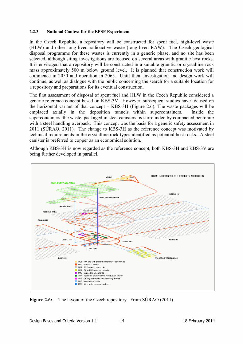
The first assessment of disposal of spent fuel and HLW in the Czech Republic considered a
generic reference concept based on KBS-3V. However, subsequent studies have focused on
the horizontal variant of that concept – KBS-3H (Figure 2.6). The waste packages will be
emplaced axially in the deposition tunnels within supercontainers. Inside the
supercontainers, the waste, packaged in steel canisters, is surrounded by compacted bentonite
with a steel handling overpack. This concept was the basis for a generic safety assessment in
2011 (SÚRAO, 2011). The change to KBS-3H as the reference concept was motivated by
technical requirements in the crystalline rock types identified as potential host rocks. A steel
canister is preferred to copper as an economical solution.
Although KBS-3H is now regarded as the reference concept, both KBS-3H and KBS-3V are
being further developed in parallel.
Figure 2.6: The layout of the Czech repository. From SÚRAO (2011).

Design Bases and Criteria Version 1.1 15 18 February 2014
Plugs and Seals in the Czech Reference Disposal Concept
In the Czech reference concept, a plug is defined as a structure for closure of tunnels in the
repository. Seals are defined as hydraulic components for closure of large-diameter (several
meters) underground installations and infrastructure components, including shafts, ramps and
drifts.
The EPSP test is not a test of a specific plug or seal, but is undertaken at a similar scale to a
deposition tunnel plug, and will contribute specifically to the development of the reference
design for these structures. The objective of the EPSP experiment is to test the materials and
technology for implementation, not to test the design or performance of the reference
deposition tunnel plug. At this early stage in the Czech geological disposal programme, with
more than 50 years before operations are scheduled to begin, it is considered more important
to build knowledge and experience than refine designs for implementation in an, as yet,
unidentified site with unknown mechanical, hydrogeological and chemical characteristics.
2.2.4 National Context for the FSS Experiment
Reference Disposal Concept in France
In France, the repository host rock is the 155-million-year-old Callovo-Oxfordian Clay
formation, located in the Meuse and Haute Marne Departments, which lie in the east of the
Paris Basin. The repository is referred to as the Centre Industriel de Stockage Géologique
(Cigéo), and implementation of geological disposal as the Cigéo Project. The reference
disposal inventory includes long-lived intermediate-level waste (LL-ILW) from operation,
maintenance and decommissioning of nuclear facilities and HLW from spent fuel
reprocessing. The reference disposal inventory also includes a small volume (27 m3) of spent
fuel which does not have characteristics suitable for recycling. The waste will be disposed of
in physically separated disposal zones: one for ILW and one for HLW. The repository’s
primary function is to isolate the waste from activities at the surface and its second function is
to confine radioactive substance and control the transfer pathways which may in the long
term bring radionuclides into contact with humans and the environment (Andra, 2013). The
principal contribution of the seals in Andra’s concept is to the second function.
The ILW disposal area includes several tens of large-diameter disposal vaults, each about
400-500-m long. Waste packages consist of primary waste containers emplaced in a concrete
disposal container. Vault concrete lining and disposal containers provide a cementitious
environment for the waste. The gaps between waste packages and vault lining could be left
empty or backfilled with cementitious material or neutral filler (e.g. Pozzolans).
The HLW disposal area includes several hundred disposal cells in the form of small-diameter
steel-lined boreholes that are tens of metres in length. The steel lining enables emplacement
and potential retrieval of waste packages. The waste packages consist of a primary HLW
stainless steel canister and a carbon steel overpack. No buffer material is placed in the
disposal cells, but grout is injected in the upper part of the annular gap between the rock wall
and the steel liner.
For closure operations, the excavated host rock is used to backfill the drifts, shafts and access
ramps with the concrete lining maintained. The repository facilities will remain in service for
about 120 years, with ILW and HLW with a relatively low heat output being disposed of in
the first 70-80 years and HLW that currently has a relatively high heat output being disposed
of afterwards (after a surface storage period for thermal decay).

Design Bases and Criteria Version 1.1 16 18 February 2014
Plugs and Seals in the French Reference Disposal Concept
In the French concept, seals are defined as hydraulic components for closure of large
diameter (several meters) underground installations and infrastructure components such as
shafts, ramps, drifts1 and ILW disposal vaults. Each seal consists of a swelling clay core and
concrete containment walls. The conceptual design of drift and ILW disposal vault seals is
the same. The FSS experiment is a full-scale technical demonstration of construction
feasibility for a drift and ILW disposal vault seal.
Plugs are defined as components for closure of the small diameter (several decimetres) HLW
disposal cells.
Seals and plugs are collectively referred to as “closure components”. The design and location
of plugs are not dealt with in the present document.
The locations of seals in the planned Cigéo repository are shown in Figure 2.7.
Figure 2.7: Locations of the seals in the French repository concept.
1 Drifts are horizontal tunnels, whereas ramps are inclined tunnels.

Design Bases and Criteria Version 1.1 17 18 February 2014
2.2.5 National Context for the ELSA Experiment
The future strategies for site selection and licensing for a repository for HLW in Germany are
currently under discussion. Therefore, information provided below is based on previous
proposals of a repository located at Gorleben in a salt dome.
Previous Reference Disposal Concept for Gorleben
The reference concept for disposal of spent fuel, HLW, ILW, graphite and depleted uranium
is based on a repository design for the Gorleben salt dome. A site-specific research project,
the Preliminary Safety Analysis for Gorleben (VSG), was conducted between July 2010 and
March 2013. It documents the results of the Gorleben investigations achieved so far. The
results were to be used to update the emplacement concepts, repository layout, sealing and
performance assessment, and to identify any remaining open questions. Discussion of the
reference concept for the Gorleben salt dome below focuses on spent fuel and HLW.
The repository concept considered in the VSG assumed disposal at a depth of 870 m, in a
series of twelve emplacement fields. The layout of the repository is shown in Figure 2.8.
Two emplacement concepts have been considered: horizontal drift disposal of Pollux casks
and vertical borehole emplacement of BrennStabKokille-3 (BSK-3) containers.
Figure 2.8: Layout of the Gorleben repository in the horizontal drift concept.

Design Bases and Criteria Version 1.1 18 18 February 2014
In the horizontal drift disposal concept, waste packages are emplaced horizontally on the
floor. After the containers have been emplaced, the void spaces of the emplacement drifts are
backfilled with dry crushed rock salt. There is no requirement to seal each single
emplacement drift. Optionally, the emplacement field can be sealed with a 10-m-long MgO
plug at both ends of the access tunnels for operational reasons. These plugs have no safety
function during the post-closure phase.
For the vertical borehole disposal concept, waste packages are emplaced vertically in
boreholes with a depth of up to 300 m. The boreholes are supported by steel liners to provide
the possibility of waste retrieval. The void spaces between the steel liner and the containers
are backfilled with quartz sand. After a borehole is filled, it will either be sealed with a steel
lid or with an MgO plug for operational reasons. These plugs have no safety function during
the post-closure phase.
The main transport drifts are backfilled with crushed salt, with a water content of 0.6% by
weight, to accelerate the compaction process. Drift seals are located close to the
infrastructure area in the vicinity of the two shafts. Each drift seal consists of two 50-m-long
sealing elements made of MgO-based concrete and three support elements. The total length
of a drift seal is about 150 m. The infrastructure area is backfilled with non-compactible
serpentine gravel to allow potential brines and gases to accumulate. The shafts are both
backfilled and sealed over a length of nearly 600 m with a sequence of three sealing elements
and multiple static abutments.
The operational period of the repository is assumed to be from 2035 to 2074. The plan for
the operational sequence was developed as follows:
1. Emplacement starts in the area most distant from the shafts.
2. Void spaces around each container are backfilled with salt grit immediately after
emplacement.
3. After all emplacement drifts of an emplacement field are loaded, the connection
gallery is backfilled and sealed at both ends with an MgO-plug of 10 m length.
4. The access drifts are backfilled with salt grit
5. The access drifts are sealed with a drift seal after emplacement is completed.
6. The infrastructure area is backfilled with gravel.
7. The shafts are sealed with shaft seals.
Steps 1 to 4 are successively performed during operation and steps 5 to 7 during closure of
the repository. The time needed for closure was estimated at five years. Therefore,
according to this schedule, the construction of drift and shaft seals would not start before the
end of 2060s.

Design Bases and Criteria Version 1.1 19 18 February 2014
Plugs and Seals in the German Reference Disposal Concept
The term “seal” is defined in the Safety Requirements promulgated by the German regulator
Bundesministerium für Umwelt, Naturschutz und Reaktorsicherheit (BMU) (BMU, 2010) as
follows:
“A seal refers to both the sealing of the emplacement zones by flush mount backfilling
of selected galleries and underworkings, as well as the sealing of the shafts in the
repository mine. The seal includes all technical structures incorporated into the
repository mine in order to safeguard the integrity of the isolating rock zone and
protect against ionising radiation”
The definition of a “sealing element” is (Mönig et al., 2012):
“A sealing element is part of a technical barrier. It has the function to hinder the flow
of fluids and the transport of radionuclides”
The term “technical” used in those definitions refers to engineered components of the system,
so a “technical barrier” is an engineered barrier, as opposed to a natural barrier.
There are seals that are only foreseen as having a function during the operational period of
the repository and others specifically contributing to long-term safety. The seals providing an
operational safety function are either borehole seals placed on top of each emplacement
borehole in the vertical emplacement concept or seals to isolate each emplacement area in
case of the horizontal emplacement concept. For long-term safety, there are two types of
seals – shaft seals and drift seals. The previous Gorleben repository concept envisages two
shaft seals, one in each shaft, and four drift seals. The location of the drift seals is shown in
Figure 2.9. The ELSA experiment concerns large-scale demonstrations of shaft seal
elements.
Figure 2.9: The four locations of sealing elements (D) and static abutments (WL) of the
four drift seals.

Design Bases and Criteria Version 1.1 20 18 February 2014
2.2.6 Plugs and Seals in other Concepts
The Netherlands
The Dutch programme is in the generic phase. There are currently two disposal concepts
under consideration: disposal of HLW and ILW in a clay host rock in horizontal tunnels, and
disposal in vertical boreholes and large excavated rooms in a salt host rock.
In the Dutch concept, plugs and seals are not explicitly defined. However, the outline
disposal concept in clay (OPERA, 2011) states:
“A plug is used to hydraulically seal off a disposal drift after emplacement of waste
packages. Seals are used to seal the shafts and ramp when the facility is closed.”
In clay host rocks, shaft seals and drift plugs must suppress flow of water through the
repository after it has been resaturated with water from the host rock. In salt rocks, shaft and
drift seals must ensure that the waste and waste packages remain dry until they are
completely isolated by the impermeable rock salt.
Switzerland
It is envisaged that repositories for HLW and ILW will be built in a clay-rich host rock, with
several sites currently under consideration. It has not yet been decided whether one
repository will be constructed for both HLW and ILW or one for each type of waste. For
HLW, carbon steel disposal canisters will be emplaced horizontally in dead-end tunnels of
~2.5-m diameter and several hundreds of meter length and several tens of meters apart.
Hydraulic seals are foreseen in between each tenth canister and at the end of each
emplacement tunnel. For ILW, caverns of 6-12 m diameter are envisaged. The final design
option of the caverns strongly depends on the site-specific geological conditions.
In the Swiss repository concept, seals are defined as elements that hydraulically isolate parts
of the repository system and/or the repository from the geosphere and biosphere. Seals are
composed of a sealing element (e.g. bentonite) and mechanical supporting elements (e.g.
concrete and gravel). Plugs are defined as temporary mechanical seals, and have no long-
term safety functions.
The following primary functions of the different seal components need to be achieved:
Sealing element (e.g. bentonite, sand-bentonite mixture): suitable materials are
chosen ensuring low hydraulic conductivity, high conductivity for gas, high
radionuclide retention, and a swelling behaviour to reduce excavation damage zone
(EDZ) porosity after resaturation of the system.
Supporting elements (e.g. concrete, rock blocks, gravel): these provide a mechanical
support load to facilitate adequate emplacement of the sealing element, and to protect
it from high differential water pressures or gas pressures.
Transition layer (filter layer) (gravel, sand): this can act as a “buffering of
chemistry” layer to avoid/limit chemical interactions between the seal, support
material, and backfill material.
In the Swiss concept, requirements on plugs and seals are derived from, and depend on,
details of repository design and layout.

Design Bases and Criteria Version 1.1 21 18 February 2014
The UK
At the current stage of the UK programme, NDA RWMD are examining a wide range of
potentially suitable disposal concepts so that a well-informed assessment of options can be
carried out at appropriate decision points in the implementation programme. The programme
is in the generic phase and considers three possible host rocks: higher-strength rocks, lower-
strength sedimentary rocks, and evaporites. NDA RWMD has set out illustrative concepts
for each of the three host rocks, including the associated variants on overlying rocks. A
reference case conceptual design that uses the illustrative disposal concept examples for
higher-strength rocks comprises:
The concept previously developed in the UK for ILW/LLW disposal (Nirex, 2005).
The KBS-3V method developed in Sweden and Finland for the disposal of spent fuel.
In the UK, sealing systems are defined as engineered seals that will be used to prevent the
flow of fluids in excavated tunnels (NDA RWMD, 2010a). Seals may be placed where parts
of the rock are more permeable. In addition, the backfill and seals are defined as materials
that fill the access ways and emplacement regions of a geological disposal facility (GDF) and
isolate key aspects of it (NDA RWMD, 2010b). Complementary with the engineered seals,
the plugs, although not explicitly defined, may be considered as the component of a sealing
system, providing mechanical support and resisting the water and seal swelling pressures that
will develop.
Although the UK programme is in the generic phase, some work has focused on the
identification of the safety functions of sealing plugs. These shall be designed to (NDA
RWMD, 2010d):
Provide mechanical support to the backfill material in a disposal module and be strong
enough to withstand the combined pressure from the groundwater and the swelling of
the backfill or buffer materials.
Limit water flow from a disposal module to the access ways.
Consider requirements on gas migration from a disposal module to the access ways.
The design of the sealing systems will be developed as the programme progresses and site-
specific information becomes available.

Design Bases and Criteria Version 1.1 22 18 February 2014
2.3 Summary
In broad terms, and from the concepts described above, plugs and seals can be distinguished
by two main factors – their size and the length of time for which the fulfilment of their
functions is required. The plugs are usually smaller structures used to provide mechanical
stability of the backfill and hydraulic control in a deposition tunnel, drift or borehole. The
seals are generally larger systems intended to prevent access to other openings of a repository
after closure. Plugs are typically required to provide short-term isolation of the waste and
backfill during the operational period of a repository, whereas the seals are intended to fulfil
longer-term functions in the post-closure period. Therefore, the seals are normally
considered to be permanent installations and the plugs may only be temporary (Dixon et al.,
2009). Some organisations use other terminology to refer to the “plug” or “seal”, or indeed
use the “plug” and “seal” terms to refer to structures that do not necessarily align with the
observations presented above. Specific terminology used by several organisations is given in
Appendix C.
Plugs and seals are generally required to achieve many safety functions, among which are:
the need to prevent water flow through waste disposal areas and the need to prevent access to
the repository after it is closed. The safety functions of plugs and seals differ between
national programmes depending on the geological environment, disposal concept, and
approach to the safety case. The safety functions of plugs or seals to be tested in DOPAS are
discussed under the design basis section for each experiment.
The type of host rock plays an important role in defining the design requirements for plugs
and seals. In crystalline rocks, plugging/sealing shafts and tunnels aims to achieve a
hydraulic conductivity comparable to that of the rock mass, ensuring a good contact is
established between the plug/seal material and the rock. For clay rocks, plugs and seals need
to ensure that very low permeabilities are achieved to match those of the clay. Removal of
the host rock lining may become necessary in this regard. For salt rocks, any sealing must be
done in such a way that brine migration through the artificial openings to the waste canisters
is avoided until the backfill is sufficiently compacted.

Design Bases and Criteria Version 1.1 23 18 February 2014
3. DOMPLU Design Basis (SKB)
DOMPLU is a full-scale experiment of a deposition tunnel plug being carried out in Äspö.
This section describes the process by which the design basis for the reference deposition
tunnel plug and for the DOMPLU experiment have been developed, and describes the design
basis for both the reference deposition tunnel plug in SKB’s concept and for DOMPLU.
3.1 Process used by SKB to Develop the Plug Design Basis
3.1.1 Definition of the Design Basis and Method used to Describe the Design Basis
Within SKB’s programme, the term “design premise” is used to indicate information that
forms a necessary basis for design. Design premises comprise requirements and other
considerations for the design. Requirements express needs or expectations. Other
considerations for the design include quantitative information on features, performance,
events, loads, stresses, combinations of loads and stresses, and information regarding the
environment or adjacent systems for the design. In SKB reports, design premises are used as
a common term for all information required for the design, and no particular distinction is
made between requirements and other considerations (SKB, 2010a).
SKB manages requirements using a hierarchical system based on the V model illustrated in
Figure 3.1. The left hand side of the V model describes the work breakdown structure of
requirements and the right hand side of Figure 3.1 describes the way in which the SKB
verifies that the requirements have been met.
Figure 3.1: The V model used to manage requirements on the Swedish repository.
General Principles govern how requirements are developed and managed by SKB. They
include national laws and regulations governing disposal of spent fuel, stakeholder
requirements, and the host rock conditions and constraints. The safety functions of a
deposition tunnel plug are then defined to comply with these requirements before more
detailed design specifications are developed.
The requirements are stored in an electronic database or requirements management system
(RMS). At present, the design requirements for deposition tunnel plugs in the database are
under development. The requirements that are included in the database are only specified in
a general sense, i.e. no specific values (e.g. pressure acting on the deposition tunnel plug) are

Design Bases and Criteria Version 1.1 24 18 February 2014
provided. As described below, other specific design requirements have been identified, but,
as yet, these have not been incorporated into the requirements database.
A series of Production Reports that provide design premises for the licence application have
been produced by SKB. These reports present how the Swedish repository based on the
KBS-3V method is designed and constructed. One of these reports is the Backfill Production
Report (SKB, 2010b); it compiles the design premises for the backfill and deposition tunnel
plug.
In the initial stages of the DOMPLU Project, a sub-project was formed to manage
requirements on the plug by analysing basic knowledge and the current reference design.
Specific requirements to be used for the DOMPLU set-up were then prescribed in two
internal memos – a memo with requirements for the plug location and a memo describing
design criteria for the DOMPLU plug structure (Palmer, 2011). These requirement memos
were reviewed and approved before the go-ahead was given for the project to start. The
development of the DOMPLU design took approximately one year and involved knowledge
sharing and coordination between cross-functional areas (rock, concrete, clay, etc.) and
engagement of several experienced staff.
3.1.2 Development of the Design Basis
The design basis for deposition tunnel plugs has been in development for many decades,
driven by the learning gained from more detailed knowledge on the repository site conditions
and from full-scale experiments and laboratory tests in Sweden and elsewhere. These
experiments have been undertaken in collaboration with Posiva and have also fed in to the
development of the reference deposition tunnel plug in the Posiva disposal concept.
The need for a plug at the entrance to a deposition tunnel was recognised at an early stage of
the Swedish programme as a means of maintaining the backfill in place and having a
compartment which has a higher water head than the open galleries in the repository.
Different designs have been tested in previous full-scale experiments, including:
The Stripa mine tunnel plugging experiment in the 1980s.
The Äspö Backfill and Plug Test in the 1990s.
The Äspö Prototype Repository in the 2000s.
The Äspö short plug test for the horizontal emplacement concept in 2005.
A simple design of a plug was tested in the Stripa mine in Sweden as part of the Tunnel
Plugging Experiment in the 1980s (see Figure B.1). An O-ring of bentonite was introduced
into the design after this experiment, and was tested in the Backfill and Plug Test at the
ÄHRL in the late 1990s and early 2000s (Figure B.2). The O-ring did not perform as
intended, as leakage of water was found to be quite high. Subsequent to these experiments,
the Prototype Repository, incorporating two plugs, was built at the ÄHRL, beginning in 2001
(Figure B.3). Unlike previous experiments, both concrete plugs were cast with SCC. As part
of the ESDRED Project, a low-pH shotcrete plug was tested for horizontal emplacement of
disposal containers (Figure B.5). Significant water leakage was observed at the bottom of the
plug. Another experiment from which valuable experience has been gained is the Canadian
Tunnel Seal Experiment (TSX) (Figure B.4). Very small seepage of water through the
concrete plug and bentonite seal were measured in this experiment.

Design Bases and Criteria Version 1.1 25 18 February 2014
3.2 Design Basis for the Reference Deposition Tunnel Plug
The current SKB reference conceptual design for a deposition tunnel plug includes the
following components (Figure 3.2):
Concrete plug: The concrete plug is made of reinforced concrete. It contains pipes
for auxiliary equipment such as an air ventilation pipes, cooling pipes, and grouting
tubes. The function of the concrete plug is to resist deformation and to keep the
watertight seal, filter and backfill in place
Watertight seal: The watertight seal is made of bentonite blocks and pellets in a
similar configuration as the backfill. Its function is to seal water leakage paths
through small cracks in the concrete plug or between the concrete and the rock
surface, and to take up the water pressure gradient over the plug so that no
unfavourable water pressure is applied in the interface between the rock and the
concrete and so that the water pressure within the backfilled deposition tunnel is
equalised.
Filter: The filter is made of sand or gravel. Its function is to collect water leaking
from the backfill and if required drain it to the drainage pipes, so that no water
pressure is applied on the concrete plug before it has cured and gained full strength.
Concrete beams: The beams are made of reinforced concrete. The outer beams
(towards the concrete plug) are covered with a thin layer of shotcrete to prevent the
concrete slurry from mixing with the bentonite during casting of the concrete plug.
The concrete beams shall facilitate the construction works. The inner beams (towards
the deposition tunnel) shall keep the backfill in place during installation. The middle
beams shall keep the filter in place during installation and are designed to withstand
the development of the pressure during compaction of the filter material. The outer
beams (towards the concrete plug and main tunnel) shall keep the bentonite blocks in
the watertight seal in place during installation.
Drainage pipes: The drainage pipes need to be resistant throughout the sealing phase,
and are made of steel or titanium. They shall drain the water collected in the filter and
transport it out from the deposition tunnel to prevent water pressure being applied on
the concrete plug before it has cured and gained full strength.
Grouting pipes: The grouting pipes are made of steel and may be isolated by
geotextile to prevent blocking during pouring. They shall be grouted when the
concrete has reached a certain level of strength. The grout shall tighten the contact
area between the concrete plug and rock and contribute to keeping the concrete plug
pre-stressed.
Deposition tunnel plugs in the Swedish repository are not prime safety barriers, but they have
temporary functions with the objective of supporting the performance of other safety barriers.
Their functions during the operational period of the repository are to:
Confine the backfill in the tunnel.
Support saturation in the backfill.
Provide a barrier against water flow that may cause harmful erosion of the bentonite
buffer and bentonite backfill.

Design Bases and Criteria Version 1.1 26 18 February 2014
Figure 3.2: Schematic of the deposition tunnel plug SKB conceptual design (SKB, 2010b).
The design premises for the reference deposition tunnel plug are provided in Table 3.1.
These are derived from the SKB RMS, internal working documents, the Backfill Production
Report and through developments undertaken within the DOPAS Project. As noted above,
the deposition tunnel plug requirements in SKB’s RMS have not yet been fully developed,
and, are defined in a general sense. For example, Design Requirement Plug (DRP) 33
requires that the “plug must not decrease as much in volume that backfill functions are
compromised”, but, as yet the allowable volume reduction has not been quantified.
The design basis for the deposition tunnel plug is divided into three phases:
The Production Phase, including Construction and Curing: This phase comprises the
installation and the period until the plug has gained full strength. The main
installation considerations in this phase are for the plug to be prepared and installed
with high reliability, at the prescribed rate, using well–tried and tested techniques, and
in a cost-effective manner. In the curing period, the design of the deposition tunnel
plug must ensure that the full pressure against the concrete plug must not appear until
it has cured and gained sufficient strength. In the conceptual deposition tunnel plug
design, this is achieved by provision of the drainage pipes. However, the use of
drainage pipes is not explicitly prescribed in the requirements of the design basis.
The Sealing Phase: refers to the period from the end of the production phase until the
time when the adjacent main tunnel to the plug is filled and saturated. The functions
of the plug during this phase are to resist the hydrostatic pressure and swelling
pressure of the backfill until the main tunnel is filled, to limit water flow until the
main tunnel is filled and saturated, and to be durable – the design working life is 100
years.
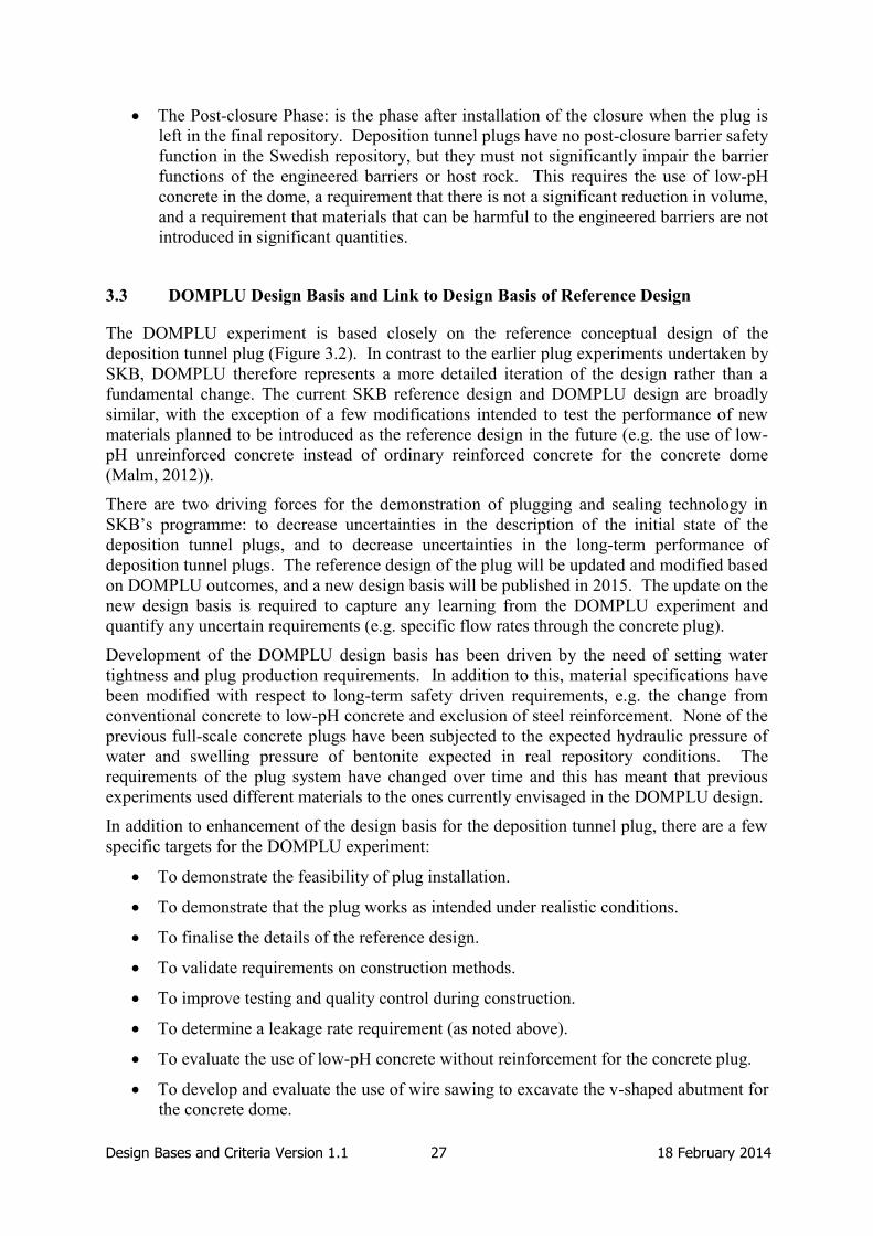
Design Bases and Criteria Version 1.1 27 18 February 2014
The Post-closure Phase: is the phase after installation of the closure when the plug is
left in the final repository. Deposition tunnel plugs have no post-closure barrier safety
function in the Swedish repository, but they must not significantly impair the barrier
functions of the engineered barriers or host rock. This requires the use of low-pH
concrete in the dome, a requirement that there is not a significant reduction in volume,
and a requirement that materials that can be harmful to the engineered barriers are not
introduced in significant quantities.
3.3 DOMPLU Design Basis and Link to Design Basis of Reference Design
The DOMPLU experiment is based closely on the reference conceptual design of the
deposition tunnel plug (Figure 3.2). In contrast to the earlier plug experiments undertaken by
SKB, DOMPLU therefore represents a more detailed iteration of the design rather than a
fundamental change. The current SKB reference design and DOMPLU design are broadly
similar, with the exception of a few modifications intended to test the performance of new
materials planned to be introduced as the reference design in the future (e.g. the use of low-
pH unreinforced concrete instead of ordinary reinforced concrete for the concrete dome
(Malm, 2012)).
There are two driving forces for the demonstration of plugging and sealing technology in
SKB’s programme: to decrease uncertainties in the description of the initial state of the
deposition tunnel plugs, and to decrease uncertainties in the long-term performance of
deposition tunnel plugs. The reference design of the plug will be updated and modified based
on DOMPLU outcomes, and a new design basis will be published in 2015. The update on the
new design basis is required to capture any learning from the DOMPLU experiment and
quantify any uncertain requirements (e.g. specific flow rates through the concrete plug).
Development of the DOMPLU design basis has been driven by the need of setting water
tightness and plug production requirements. In addition to this, material specifications have
been modified with respect to long-term safety driven requirements, e.g. the change from
conventional concrete to low-pH concrete and exclusion of steel reinforcement. None of the
previous full-scale concrete plugs have been subjected to the expected hydraulic pressure of
water and swelling pressure of bentonite expected in real repository conditions. The
requirements of the plug system have changed over time and this has meant that previous
experiments used different materials to the ones currently envisaged in the DOMPLU design.
In addition to enhancement of the design basis for the deposition tunnel plug, there are a few
specific targets for the DOMPLU experiment:
To demonstrate the feasibility of plug installation.
To demonstrate that the plug works as intended under realistic conditions.
To finalise the details of the reference design.
To validate requirements on construction methods.
To improve testing and quality control during construction.
To determine a leakage rate requirement (as noted above).
To evaluate the use of low-pH concrete without reinforcement for the concrete plug.
To develop and evaluate the use of wire sawing to excavate the v-shaped abutment for
the concrete dome.

Design Bases and Criteria Version 1.1 28 18 February 2014
To evaluate the design and performance of the filter and watertight seal that were
introduced into the reference design after the testing of tunnel plugs in the Prototype
Repository.
To evaluate the use of lightweight expanded clay/concrete aggregate (LECA) beams
as delimiters.
To evaluate the use of gravel material 2-4 mm in size as part of the filter and its
interaction with the drainage pipes.
The design basis for DOMPLU is established around the design basis for the reference
deposition tunnel plugs presented in the previous section, but is presented in a more detailed
fashion. The design basis for the reference plug design does not include detailed design
specifications. In particular, there is no quantitative requirement on the rate of water leakage
through the plug. This will be decided based on DOMPLU results and introduced as a design
premise in the future.
The design basis for the DOMPLU experiment is provided in Table 3.2. The design premises
are structured into the same three phases as the design premises for the reference deposition
tunnel plug.
The design criteria for the DOMPLU plug structure are grouped as follows (Palmer, 2011):
Experiment site and how to choose the specific plug location (characterisation): the
strength and properties of the rock in the area of the recess with the concrete dome
have to be suitable for construction. This means that long fractures should not be
present at the plug location to prevent leakage of water.
Rock excavation method: this requires that the rock surfaces connecting the concrete
dome abutment to be free from EDZ and smooth. The rock excavation recommended
is wire-sawing.
Functional requirements: this includes a requirement for small leakage of water
through the plug. Although no specific value for the rate of water leakage has been
assigned, it is predicted that values lower than 0.085 l/min can be achieved
(i.e. < 10% of inflowing water). Another important functional requirement is the use
of a transition backfill zone so that the backfill swelling pressure is reduced from
~6-10 MPa to ~2 MPa
Geometrical requirements: these include requirements on the tunnel dimensions,
concrete dome geometry, and the shape of the excavated slot.
Material properties for all plug components: including the filter material, bentonite
seal, the delimiters, concrete dome, drainage pipes, cooling pipes, and grouting pipes.
Low-pH concrete based on the B200 recipe (Vogt et al., 2009) is used for the concrete
dome.
Load cases: a nominal design value of 5 MPa for water pressure and 4 MPa for
backfill swelling pressure are assumed, although a resulting backfill pressure of only
2 MPa is expected.
Design of the experiment set-up including the control programme and data to be
recorded.

Design Bases and Criteria Version 1.1 29 18 February 2014
Table 3.1: Design basis for reference deposition tunnel plugs in the Swedish concept.
Phase Function, Property or Design
Consideration
Design Premises and
Requirements
Production
(Construction
and including
Curing Phase)
Plugs with specified properties shall be
possible to prepare and install with high
reliability
The thermal, viscoelastic and shrinkage
properties of the concrete shall be such
that internal cracking in the young
concrete will not compromise the ability of
the plug to achieve its functional
requirements
The filter material, its grain size
distribution and compaction shall be such
that the filter can collect and drain water so
that the concrete plug is not exposed to
high water pressures until it has gained
sufficient strength
The curing of the concrete plug shall take
place without the formation of cracks
The full pressure against the concrete plug
must not appear until it has cured and
gained sufficient strength
The construction shall result in a plug with
acceptable properties and be repeatable
and reliable
The frequency of the event “Malfunction
of the plug causing retrieval of installed
backfill” shall be low (frequency of 10-3
or
less per installed plug)
Material composition and amounts shall be
recorded
The time until the plug is installed and can
achieve its functions may not be longer
than the time it takes for the pellet-filled
part of the deposition tunnel volume to be
filled with water (Requirement DRP21)
Installation of the plug shall be possible
to perform in the prescribed rate
To limit the transport of clay material out
from the deposition tunnel until the plug
has been installed and gained its full
strength and water tightness shall be as
short as possibly achievable
The plug and methods for preparation,
installation, test and inspection shall be
based on well-tried or tested technique
The methods for construction and
inspection of the plug shall as far as
possible be based on experiences and
established practice from similar
applications
If there is a lack of experiences the
reliability of the methods shall be tested
and demonstrated
The plug and method to install, control
and verify the plug shall be cost-effective
Not specified further.

Design Bases and Criteria Version 1.1 30 18 February 2014
Phase Function, Property or Design
Consideration
Design Premises and
Requirements
Sealing Phase
The plug shall resist the hydrostatic
pressure at repository depth and the
swelling pressure of the backfill until the
main tunnel is filled
The sum of the hydrostatic water pressure
at the repository level and the swelling
pressure from the backfill in the tunnel
section adjacent to the watertight seal
5 MPa water pressure and the swelling
pressure from the backfill in the section
adjacent to the plug. Currently, the backfill
swelling pressure is assumed to be 2 MPa
with the help of backfill transition zone
that decreases the load from a high load to
2 MPa
The strength and dimensioning load of the
concrete plug.
The plug strength must be sufficient to
withstand the pressure that occurs during
the sealing phase (Requirement DRP22)
The plug must withstand thermal loads
caused by the rock and concrete expansion
during the sealing phase (Requirement
DRP30)
The plug shall limit water flow until the
adjacent main tunnel is filled and
saturated
The accepted water volume will depend on
the acceptable transport of clay material
out from the deposition tunnel during this
phase and remains to be determined
The plug must be sufficiently tight to
prevent erosion of the backfill and buffer
materials out of the deposition tunnel
(Requirement DRP26)
The abutment between rock and concrete
must be sufficient to keep the plug in place
and maintain it tight (Requirement
DRP29).
The plug shall be durable and maintain
its functions in the environment expected
in the repository facility and repository
until the closure in the main tunnel is
saturated
The displacement of the concrete plug that
can be accepted with respect to the
decrease in density and resulting increase
in conductivity of the watertight seal
The strength of the concrete dome needs to
withstand the expansion of the rock caused
by heating from the emplaced spent fuel
The temperature variations that can be
expected at repository depth, i.e. the
increase in repository temperature caused
by the decay power of the spent nuclear
fuel, and situations where repository
temperature does not increase due to
ventilation related heat transfer in the main
tunnels

Design Bases and Criteria Version 1.1 31 18 February 2014
Phase Function, Property or Design
Consideration
Design Premises and
Requirements
Sealing Phase
The design working life is 100 years,
therefore all requirements on the plug
during the sealing phase shall be met for
100 years
In addition, there are requirements for the
concrete tightness and durability in the
repository.
Post-closure
Phase
The plug must not significantly impair
the barrier functions of the engineered
barriers or rock
The volume of the plug shall not decrease
and lead to a loss in backfill density such
that the barrier functions of the backfill are
significantly reduced
Low-pH concrete that generate a leachate
with a pH ≤11 shall be used
The amount of organic materials shall be
limited
The plug must not contain content that
could be harmful to the engineered barriers
(Requirement DRP35)
The material of the plug shall remain in
place in the repository and the plug must
not decrease as much in volume that
backfill functions are compromised
(Requirement DRP33)

Design Bases and Criteria Version 1.1 32 18 February 2014
Table 3.2: DOMPLU design basis.
Phase Function, Property or Design
Consideration
Design Specifications and
Requirements
Production
(Construction
and including
Curing Phase)
Plugs with specified properties shall be
possible to prepare and install with high
reliability.
The delimiter, tentatively designed as
reinforced concrete and/or Leca beams
shall facilitate construction works and
keep the different materials separated and
in place.
For parts of the concrete dome with
smaller width (smaller volume per lift
height) up to 100 cm/hour is acceptable if
required for the concrete pumping
equipment to run continuously, and/or if
required for the mixing/transport system to
run efficiently.
The strength and properties of the rock in
the area of the recess for the concrete
dome and the anchoring for temporary
structures shall be suitable for the
construction, i.e. sufficient to resist the
pressure transmitted from the plug
structure without fracturing.
Other requirements and design
specifications for DOMPLU that do not
map to the functions, properties or design
considerations in the reference design.
Rock excavation at plug section shall
follow requirements as given for
deposition tunnel.
Swedish regulations for underground
constructions shall be applied.
The location of the plug shall be at the
tightest section of rock identified in a pilot
borehole through water injection tests and
core characterisation.
Theoretical tunnel area deposition tunnel:
19.4 m2 (H=4.8m, B=4.2m) with an
expected area variation from 21.4 to
25 m2.
The abutment cross section shall be either
circular, octagonal or hexadecagonal (16-
sided).
Installed dry density of filter material is >
1400 kg/ m3.
The thickness of the filter layer is 0.6m.
In DOMPLU, the filter will comprise one
layer of 300mm Leca beams (also serving
as delimiter) and one 300mm layer of
macadam (fraction 2-4mm). Compaction
of the macadam layer is not considered
necessary for DOMPLU
Voids between rock and filter Leca beams
shall be minimized and filled with
macadam.
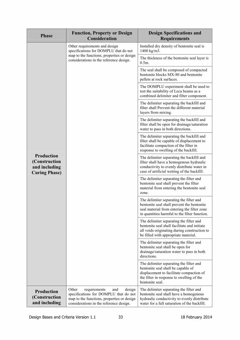
Design Bases and Criteria Version 1.1 33 18 February 2014
Phase Function, Property or Design
Consideration
Design Specifications and
Requirements
Production
(Construction
and including
Curing Phase)
Other requirements and design
specifications for DOMPLU that do not
map to the functions, properties or design
considerations in the reference design.
Installed dry density of bentonite seal is
1400 kg/m3.
The thickness of the bentonite seal layer is
0.5m.
The seal shall be composed of compacted
bentonite blocks MX-80 and bentonite
pellets at rock surfaces.
The DOMPLU experiment shall be used to
test the suitability of Leca beams as a
combined delimiter and filter component.
The delimiter separating the backfill and
filter shall Prevent the different material
layers from mixing.
The delimiter separating the backfill and
filter shall be open for drainage/saturation
water to pass in both directions.
The delimiter separating the backfill and
filter shall be capable of displacement to
facilitate compaction of the filter in
response to swelling of the backfill.
The delimiter separating the backfill and
filter shall have a homogenous hydraulic
conductivity to evenly distribute water in
case of artificial wetting of the backfill.
The delimiter separating the filter and
bentonite seal shall prevent the filter
material from entering the bentonite seal
zone.
The delimiter separating the filter and
bentonite seal shall prevent the bentonite
seal material from entering the filter zone
in quantities harmful to the filter function.
The delimiter separating the filter and
bentonite seal shall facilitate and initiate
all voids originating during construction to
be filled with appropriate material.
The delimiter separating the filter and
bentonite seal shall be open for
drainage/saturation water to pass in both
directions.
The delimiter separating the filter and
bentonite seal shall be capable of
displacement to facilitate compaction of
the filter in response to swelling of the
bentonite seal.
Production
(Construction
and including
Other requirements and design
specifications for DOMPLU that do not
map to the functions, properties or design
considerations in the reference design.
The delimiter separating the filter and
bentonite seal shall have a homogenous
hydraulic conductivity to evenly distribute
water for a full saturation of the backfill.
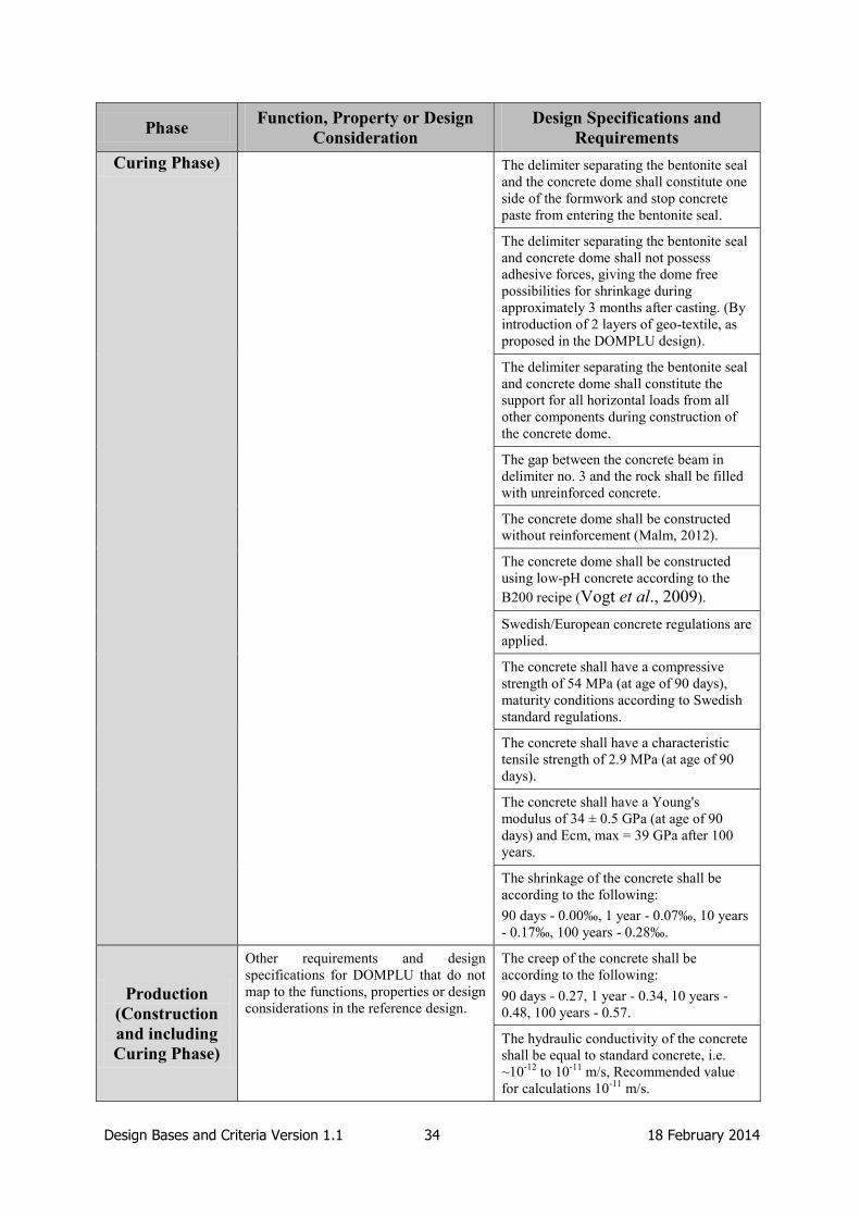
Design Bases and Criteria Version 1.1 34 18 February 2014
Phase Function, Property or Design
Consideration
Design Specifications and
Requirements
Curing Phase) The delimiter separating the bentonite seal
and the concrete dome shall constitute one
side of the formwork and stop concrete
paste from entering the bentonite seal.
The delimiter separating the bentonite seal
and concrete dome shall not possess
adhesive forces, giving the dome free
possibilities for shrinkage during
approximately 3 months after casting. (By
introduction of 2 layers of geo-textile, as
proposed in the DOMPLU design).
The delimiter separating the bentonite seal
and concrete dome shall constitute the
support for all horizontal loads from all
other components during construction of
the concrete dome.
The gap between the concrete beam in
delimiter no. 3 and the rock shall be filled
with unreinforced concrete.
The concrete dome shall be constructed
without reinforcement (Malm, 2012).
The concrete dome shall be constructed
using low-pH concrete according to the
B200 recipe (Vogt et al., 2009).
Swedish/European concrete regulations are
applied.
The concrete shall have a compressive
strength of 54 MPa (at age of 90 days),
maturity conditions according to Swedish
standard regulations.
The concrete shall have a characteristic
tensile strength of 2.9 MPa (at age of 90
days).
The concrete shall have a Young's
modulus of 34 ± 0.5 GPa (at age of 90
days) and Ecm, max = 39 GPa after 100
years.
The shrinkage of the concrete shall be
according to the following:
90 days - 0.00‰, 1 year - 0.07‰, 10 years
- 0.17‰, 100 years - 0.28‰.
Production
(Construction
and including
Curing Phase)
Other requirements and design
specifications for DOMPLU that do not
map to the functions, properties or design
considerations in the reference design.
The creep of the concrete shall be
according to the following:
90 days - 0.27, 1 year - 0.34, 10 years -
0.48, 100 years - 0.57.
The hydraulic conductivity of the concrete
shall be equal to standard concrete, i.e.
~10-12
to 10-11
m/s, Recommended value
for calculations 10-11
m/s.

Design Bases and Criteria Version 1.1 35 18 February 2014
Phase Function, Property or Design
Consideration
Design Specifications and
Requirements
All material components must be available
in the market, and be able to be mixed with
standard concrete mixing equipment.
The concrete must be pumpable, slump-
flow test target value ~730 mm. High
internal stability to minimize the risk for
separation/ segregation. Requirement for
segregation ≤ 10 %.
The temperature of concrete upon arrival
to the DOMPLU experiment site shall be
less than or equal to 20ºC.
Contact grouting shall be performed using
Standard Portland (Ultrafin 16 or
Cement 30) Micro-cement and Silicasol to
be consistent with requirements for the
design basis of the reference plug design.
For DOMPLU, a 2-stage grouting
technique shall be used such that the inner
and outer cross sections are grouted first,
and the central cross section grouted
separately with higher pressure.
Standard steel shall be used for
reinforcement in beams.
Standard steel shall be used for drainage
pipes in DOMPLU.
Drainage pipes and valves shall be
designed for the internal total water
pressure (5 MPa).
Drainage pipes shall have a diameter of
40 mm.
Drainage pipes shall be in a straight
alignment when passing centrally in the
dome.
Copper shall be used for cooling pipes in
the concrete dome in DOMPLU.
Grouting hoses shall be made of PVC
material.
Production
(Construction
and including
Curing Phase)
Other requirements and design
specifications for DOMPLU that do not
map to the functions, properties or design
considerations in the reference design.
After completed and approved contact
grouting all hoses shall be filled with
grout.
The geotextile shall be made of
polypropylene or polyester materials.
Lead through steel pipe for cabling passing
the concrete dome shall be designed to
withstand the maximum water pressure of
5 MPa.

Design Bases and Criteria Version 1.1 36 18 February 2014
Phase Function, Property or Design
Consideration
Design Specifications and
Requirements
In DOMPLU, pressurising pipes shall be
arranged in a separate drill-hole passing
the rock and going directly to the entrance
of the drift.
The pressurising pipes shall be provided
with steel flanges and sealing couplings
designed for maximum allowed test water
pressure of 10 MPa.
Sealing Phase
The plug shall resist the hydrostatic
pressure at repository depth and the
swelling pressure of the backfill until the
main tunnel is filled.
The bentonite seal must be kept drained
and dry until the concrete structure is
cured (~90 days) and contact grouting is
performed.
The filter material, its grain size
distribution and compaction shall be such
that the filter can collect and drain water so
that the concrete plug is not exposed to
high water pressures until it has gained
sufficient strength.
A recess for foundation of the concrete
dome shall be prepared in the rock.
Evenly and unevenly distributed load
combinations on the concrete dome shall
be considered. However, small variations
≤ ± 20 % of the average swelling pressure
can be omitted provided the maximum
swelling pressure is not exceeded at any
point and the average total load acting
upon the dome is not increased.
Earthquake load cases shall be ignored in
the calculations of concrete dome strength
since this aspect is insignificant.
Settlements in the rock foundation should
be included in the numerical analyses of
displacement.
Settlements in the rock should be modelled
with an elastic modulus value of 25 GPa.
The plug shall limit water flow until the
adjacent main tunnel is filled and
saturated.
Stop outflow of water passing the plug as
soon as possible.
Sealing Phase
The plug shall limit water flow until the
adjacent main tunnel is filled and
saturated.
The excavation method used for the
DOMPLU dome, seal and filter locations
shall minimise the EDZ.
Rock surfaces connecting to the concrete
dome abutment shall be free from EDZ
and smooth and preferably almost polished
to prevent adhesion during concrete
shrinkage and to provide excellent contact
grouting conditions. The abutment shall be
excavated using wire-sawing.

Design Bases and Criteria Version 1.1 37 18 February 2014
Phase Function, Property or Design
Consideration
Design Specifications and
Requirements
Temporary drill-holes and/or wire-sawn
cuts outside the section to be excavated
must be filled with grout or bentonite
before concrete works for the dome start.
The material zone delimiter (outside the
bentonite seal) acting as formwork during
concreting must be provided with
minimum 2 layers of geotextile to stop
adhesion and allow for free shrinkage of
the concrete dome after casting.
Lift height for concrete during casting (to
compensate for early shrinkage) shall not
normally exceed 50 cm/hour.
Detailed design calculations for the
cooling system shall be prepared to decide
the length of the cooling period (~4.7
days).
Cooling should not stop before it is
assured that the adhesion between rock and
concrete is released along the roof and
walls.
Approximately one week before the
contact grouting shall be performed
(approximately 90-100 days after casting),
the cooling system shall be restarted again
to provide the possibility to pre-stress the
grouted dome structure.
The dome structure shall approximately
90-100 days after casting be cooled and
then grouted, to provide a pre-stressing
effect counteracting the high autogenous
shrinkage in low-pH concrete.
Allowed max cooling temperature shall be
such that the temperature of the concrete is
above freezing temperature.
Sealing Phase
The plug shall limit water flow until the
adjacent main tunnel is filled and
saturated.
The target value for the acceptable leakage
through the plug is presently adopted to be
“as low as possible”.
Recent calculations predicted a leakage of
0.085 l/min. However, the DOMPLU
experiment aims to achieve values lower
than this.
In case of too high observed leakage
through a plug, it shall be possible to
pressurise the filter zone.
Drainage pipes must pass in a customized
recess (in/through two half-blocks), and
not in the pellet layer.

Design Bases and Criteria Version 1.1 38 18 February 2014
Phase Function, Property or Design
Consideration
Design Specifications and
Requirements
The plug shall be durable and maintain
its functions in the environment expected
in the repository facility and repository
until the closure in the main tunnel is
saturated.
The design working life is 100 years,
therefore all requirements on the plug
during the sealing phase shall be met for
100 years.
The frequency of malfunction of the plug
causing retrieval of installed backfill shall
be 10-3
or less per installed plug.
Expected groundwater composition at plug
location will hold high salinity content,
and a chloride content > 6 000 mg/L can
be expected frequently. Structural
components sensitive to groundwater
chemistry shall be analysed based on
detailed information obtained from SDM
Site Forsmark.
Cooling pipes shall be installed and
cooling of concrete shall be performed
from start of concreting.
Post-closure
Phase
The plug must not significantly impair
the barrier functions of the engineered
barriers or rock.
Low-pH concrete less than or equal to 11
shall be used.
Content of organic material to be limited.

Design Bases and Criteria Version 1.1 39 18 February 2014
4. POPLU Design Basis (Posiva)
POPLU is a full-scale experiment of a deposition tunnel plug being carried out by Posiva in
ONKALO. This section describes the process by which the design basis for the reference
deposition tunnel plug and for the POPLU experiment have been developed, and describes
the design basis for both the reference deposition tunnel plug in Posiva’s concept and for
POPLU.
4.1 Process used by Posiva to Develop the Design Basis
4.1.1 Definition of the Design Basis and Method used to Describe the Design Basis
In Posiva’s terminology, the system design premises comprise the objectives set for the
whole system, and the limitations set by the physical environment, technology, knowledge
and the existing operating environment (regulations, responsibilities, organisations,
resources). These design premises form the starting point for the definition of the design
basis of disposal operations (Posiva, 2012b). The term design basis refers to the current and
future environmentally-induced loads and interactions that are taken into account in the
design of the disposal system, and, ultimately, to the requirements that the planned disposal
system must fulfil in order to achieve the objectives set for safety (i.e. the design premises).
Posiva has worked collaboratively with SKB in the development of an approach to
requirements management, and, therefore, has a similar way of structuring requirements.
Posiva uses a formal requirements management system (VAHA) to capture and manage
requirements related to geological disposal on spent nuclear fuel in Finland. The VAHA
system provides a rigorous and traceable method of translating the safety principles and
concept to a set of safety functions, performance requirements and design specifications for
the various barriers in the disposal system. It aims to include all relevant requirements, their
origin, and their rationale (Posiva, 2012b). Requirements are organised into five levels in the
VAHA database:
Level 1 consists of stakeholder requirements. These are requirements arising from
laws, regulations, decisions-in-principle and other stakeholder requirements.
Level 2 consists of system requirements on the basis of Posiva owners’ requirements
and the legal and regulatory requirements listed in the previous level. Level 2
requirements define the EBS components (e.g. canisters, buffer and backfill) and the
functions of the EBS and the host rock.
Level 3 consists of subsystem requirements which are specific requirements for the
canister, buffer, backfill, closure, host rock and underground openings. At this level,
the requirements are qualitative and describe targets and properties for the EBS and
host rock performance.
Level 4 consists of design requirements that clarify and provide more details to the
Level 3 requirements. These are also qualitative in nature.
Level 5 consists of design specifications which are detailed enough to be used in the
design, construction and manufacturing of the disposal system component in question.
Specifications at this level are generally quantitative in nature.
Each requirement in the VAHA system has an identification number based on the
requirement level, system, and requirement number. For example, L4-CAN-2 relates to the
second Level 4 requirement on the canister. The Posiva design basis report (Posiva, 2012b)

Design Bases and Criteria Version 1.1 40 18 February 2014
contains all requirements for Levels 1 to 4 of the VAHA system. A series of Production Line
Reports present the Level 5 requirements (design specifications) for all EBS components.
These include outline design specifications for the closure (Posiva, 2012a) and backfill
(Posiva, 2012c). The latter includes design specifications for the reference deposition tunnel
plug.
The VAHA system has been formulated between the decisions-in-principle for disposal of
spent nuclear fuel and the repository construction licence application in response to a need for
organising the requirements. VAHA requirements have been formulated as a group effort in
Posiva with the responsible persons for subsystem development having a large role. Changes
to VAHA can be applied by making a “decision guiding requirements” (this is referred to in
Finnish as Vaatimuksia ohjaava päätös (VOP)). A VOP application is made using a template
that presents the current requirement, suggestions for changes and the rationale for the
change. VOPs are presented to the Posiva Technical Group for acceptance. Design
personnel take part in the updating of requirements and the change management procedure,
and, therefore, requirements management is undertaken in parallel with design development.
The Production Line reports provide supporting information to the construction licence
application and these are included in STUK’s on-going review. STUK’s review of the
construction licence application is expected to include review of, and feedback on, the
maturity of the repository subsystems including the deposition tunnel plug. This may lead to
further development of the design basis.
Regulatory requirements on plugs and seals arise from Finland’s nuclear legislation and
Government Decrees, and are listed in YVL guides. YVL Guide D.5, entitled “Final disposal
of nuclear waste”, is a requirement setting guide. Other parts of the YVL guides must also be
considered when necessary, including those related to operation of nuclear facilities, as the
disposal facility is regulated as a nuclear facility.
The construction work related to the disposal facility, including the construction of plugs and
seals, is regulated in part by the nuclear facility construction guides (e.g. YVL Guide
E6-E12). In the future, these will be modified to be more relevant to underground
construction.
Eurocodes, the National Building Code of Finland, occupational safety and health legislation,
and environmental protection legislation will also be followed in designing the plugs.
4.1.2 Development of the Design Basis
The design basis for deposition tunnel plugs has been developed starting with the laws and
regulations for final disposal of spent nuclear fuel in Finland. These regulations are based on
the need to secure long-term safety, operational safety, environmental aspects and national
interests.
As mentioned in Section 3.1.2, a great deal of learning has been gained from large-scale
experiments carried out as part of the cooperation between Posiva and SKB. The experience
gained has been used to further develop and improve the design basis of deposition tunnel
plugs in both Sweden and Finland.
In Finland, the reference conceptual design of the deposition tunnel plugs has been based on a
wedge-shaped structure since 1999 (Haaramo, 1999). Further consideration to the design
basis, and the advantages and disadvantages of five types of plug design were provided in a
study reported in 2009 (Haaramo and Lehtonen, 2009). The types of plug considered were: a
straight plug; a butt-shaped plug; an irregular-shaped plug; a wedge-shaped plug; and a
dome-shaped plug (Figure 4.1).

Design Bases and Criteria Version 1.1 41 18 February 2014
Haaramo and Lehtonen (2009) concluded that the wedge-shaped and dome-shaped plugs
were preferred over the other types of plugs for the following reasons:
The straight plug and the butt plug require a lot of construction materials relative to
wedge-shaped and dome-shaped plugs.
The butt plug closes the central tunnel preventing further operations being conducted
there.
The irregular plug requires significantly more reinforcement than the other types of
plug, and an extra curve in the deposition tunnel.
Furthermore, the wedge-shaped plug was considered to be less technically-challenging than
the dome-shaped plug and was therefore adopted as the reference at that time. However, in
developing the licence application for the Olkiluoto repository, Posiva decided to adopt a
dome-shaped plug as the reference because dome-shaped plugs had been successfully tested
in the Äspö Prototype Repository experiment, whereas no full-scale demonstration of the
wedge-shaped plug had been undertaken.
It is expected that further analysis of deposition tunnel plugs will be undertaken in
preparation of the operating licence for the spent fuel repository. This analysis will comprise
an iterative process involving the design basis, performance assessment, and evaluation of
safety to ensure that these aspects of the repository system are updated so that technical
feasibility and long-term safety of the disposal system are demonstrated (see Figure 4.2). The
design requirements are identified so as to enable the achievement of the performance targets
(Posiva, 2012b). A specific illustration of the role of performance assessment in
development of the design basis for POPLU is provided in Figure 4.3. It shows the
interaction between performance assessment, requirements and VOPs. This is not a complete
illustration of the entire system including all aspects of requirement management, but points
out the most important factors affecting the POPLU project. Even if the plug does not have a
long-term requirement concerning the transportation of radionuclides, it affects the other EBS
components and thus a consideration of these effects should be made in case of changes.

Design Bases and Criteria Version 1.1 42 18 February 2014
Figure 4.1: The five plug types studied in Haaramo and Lehtonen (2009).
The straight plug
The butt plug The irregular plug
The wedge plug The dome plug
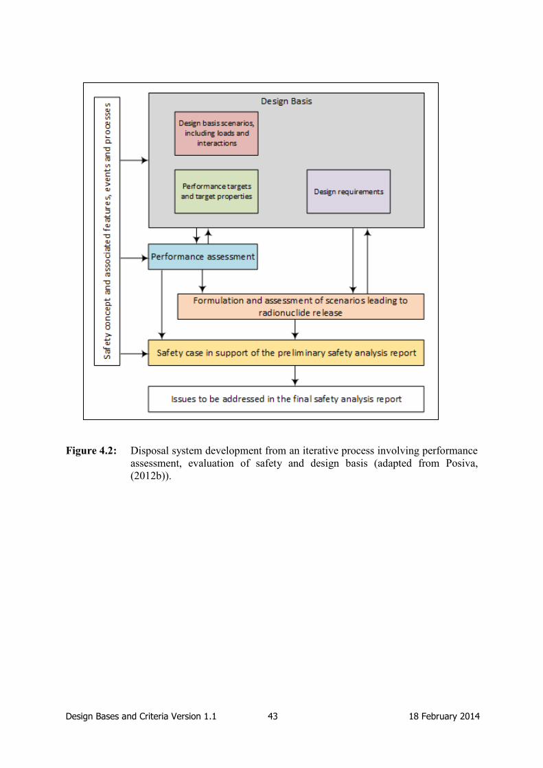
Design Bases and Criteria Version 1.1 43 18 February 2014
Figure 4.2: Disposal system development from an iterative process involving performance
assessment, evaluation of safety and design basis (adapted from Posiva,
(2012b)).

Design Bases and Criteria Version 1.1 44 18 February 2014
Figure 4.3: Illustration of the process used to develop the POPLU design basis and role of
performance assessment.

Design Bases and Criteria Version 1.1 45 18 February 2014
4.2 Design Basis for the Reference Deposition Tunnel Plug
The deposition tunnel plug design basis is compiled in the VAHA system. Requirements in
the VAHA system that relate to the reference deposition tunnel plug are provided in Table 4.1
(Levels 3, 4 and 5, including linkages between requirements from different levels and their
applicability to the POPLU experiment).
The multi-barrier system is a key element in achieving safe disposal through the provision of
long-term containment of the waste. The sealing structures of deposition tunnels are part of
the multi-barrier system and consist of the backfill and plugs. The safety functions of these
sealing structures are to:
Contribute to favourable and predictable mechanical, geochemical and
hydrogeological conditions for the buffer and canisters.
Limit and retard radionuclide releases in the possible event of canister failure.
Contribute to the mechanical stability of the rock adjacent to the deposition tunnels.
Of the above safety functions, the plug is not required to limit and retard releases, but the
plug design should be such that it does not reduce the performance of the backfill.
Requirements and specifications have been made to ensure the fulfilment of the safety
functions of the backfill and plug subsystems. Part of the subsystem requirements and
specifications are the same for both the backfill and the deposition tunnel plugs, and some are
specific to just one of these two components. The objective is to meet high-level safety
requirements by limiting water flow in the excavated openings, limit degradation of the EBS
components (especially corrosion of the canister and the erosion of the buffer and/or backfill)
and to minimize any other negative effect that the closure materials might have on other EBS
components (e.g. chemical interaction between cement and bentonite).
The deposition tunnel plug design is affected by the requirements set in response to a
consideration of long-term safety. Stray materials, water inflow, EDZ and investigation
boreholes have been identified as features and processes that can have an impact on safety
critical functions by Posiva. Of these, the presence of stray materials or an EDZ, or high
rates of water inflow can have direct consequences on the plug design. Plug materials will be
approved according to Posiva’s foreign materials guidelines. All materials introduced to
ONKALO and into the repository will need to be approved and added to a material handbook
if not yet done so. Host rock in which a significant EDZ is present will be removed from the
plug site. Any rock support introduced will not utilise rock bolts, but will, instead use other
methods, such as shotcrete or netting, but netting must not include bolts at the plug location.
Design requirements for the deposition tunnel plug state that “the plugs shall be designed to
maintain their hydraulic isolation capacity at least as long as the central tunnels are open”
(L4-BAC-6), and design specifications state that “the plug shall maintain its hydraulic
isolation capacity for at least 100 years” (L5-BAC-21). These are more related to the plugs
operational lifetime and technical feasibility. After the deterioration of the concrete, the plug
is considered to be part of the backfill subsystem and the safety functions of the backfill
provide for the long-term safety. The engineering and operational requirements are currently
not defined at the same level of detail as the long-term safety requirements in Posiva’s
VAHA system.
In some of the Level 5 requirements, specific quantitative values have been provided by
Posiva which means that it may become difficult to verify some of the requirements or
demonstrate their compliance. In future, ranges of values may be considered instead.

Design Bases and Criteria Version 1.1 46 18 February 2014
There is no value specified for a water leakage rate through the plug in the VAHA
requirements. It is generally hard to predict an exact leakage rate through the plug and
providing the correct value at this stage is not possible. It is also argued that a specific value
may be hard to verify practically after installation, especially given the large structure of the
concrete plug. Instead, requirements on bentonite material and density are specified to ensure
good sealing capacity and water tightness.
There is also no specific pH value requirement for the cementitious materials used in the
plug. The pH is implied in specifying a value for the ratio of calcium to silica content (L5-
BAC-27). This avoids the need to consider the evolution of the pH value in time. The exact
ratio in the current design basis, however, is currently being investigated and is subject to
change.
Thermal stress requirements for the plug will be considered for POPLU, and are noted in the
design of the reference plug and the design of POPLU, although not implemented. The rock
is likely to expand as a result of thermal loads from the spent fuel. The current VAHA
system does not have such a requirement.
In addition to plug-specific requirements, the VAHA system also includes requirements on
the rock where the plug will be located. It is necessary to ensure that no continuous EDZ
fractures are present at the plug location and that hydraulically conductive fractures do not
intersect the whole length of the plug. The rock requirements have been used to select the
site for POPLU.
4.3 POPLU Design Basis and Link to Design Basis
The POPLU experiment is contributing to the preparation of the operating licence application
and for carrying out the coupled disposal system test ("Yhteistoimintakoe" – a test
implementing all EBS components together, including the canister, buffer, backfill and plug)
prior the start of the operations. A proven plug solution is a crucial aspect in the safe
operations of Posiva’s disposal facility and one of the prerequisites for an operating license.
The regulatory system does not specifically demand a test construction of the deposition
tunnel plug, but there is a requirement to present evidence that the plug will perform as
required. Posiva is of the view that the best way to do this is to demonstrate plug
construction and performance in a full-scale experiment underground. Therefore, the POPLU
experiment is a response to an internal decision to undertake full-scale testing (Posiva
2012d). However, STUK oversees the construction of Posiva's facilities and further
requirements from the authorities may arise from the oversight activities during the
implementation process.
The basis for the demonstrations and experiments prior to the submission of the licence
applications are derived from Anttila et al. (2009), which defines the aims and needs of
testing and demonstrations in ONKALO.
The POPLU experiment considers an alternative design that is different to the reference plug
design. The drivers for the choice of an alternative design include:
The different rock characteristics in ONKALO compared to those that occur in the
ÄHRL, where Posiva’s previous plug experiments have been carried out in
cooperation with SKB. Specifically, there is a lower water inflow into tunnels in
ONKALO.
The provision of additional learning to that provided by the DOMPLU experiment.

Design Bases and Criteria Version 1.1 47 18 February 2014
Implementation of a simpler and cheaper wedge-shaped plug compared to the dome-
shaped plug.
At the time of writing, although the majority of the requirements, needs, conditions and
constraints (e.g. understanding of the geological environment) are understood, the design
basis is not yet complete. A POPLU design criteria document might be produced after its
design is finalised, similar to the DOMPLU design criteria report (Palmer, 2011) described in
Section 3.3. POPLU designers use information from previous Posiva reports on the wedge
plug and the VAHA requirements to develop the POPLU design.
POPLU will be a wedge-shaped reinforced concrete structure that is cast in place into a slot
that has been wire-sawed or equivalently notched to the EDZ. By providing evidence that a
simpler concrete structure with less components (possibly no filter and sealing layers as in the
reference concept) will perform as required, the plugging process could become more
straightforward to implement, as a design with less components should be easier to construct
and to model, and it may be possible to argue in the safety case that there is a better
understanding of the evolution of the plug. Should the POPLU experiment be successful,
there may be two options for the deposition tunnel plug available during the implementation
stage, and, possibly, the wedge design might replace the dome design as the reference
concept.
The current conceptual design of the POPLU wedge plug is illustrated in Figure 4.4. The
design consists of a wedge-shaped concrete structure containing grouting tubes and bentonite
circular strips at the rock-concrete interface to ensure water tightness. A backfill layer behind
the concrete structure that could be used to enable the pressurisation testing of the plug was
initially considered but is now excluded from the final POPLU design.
Although indications from modelling and design work indicate that concrete will be enough
to achieve the functions of POPLU, additional layers may be introduced between the backfill
and the plug. The layers may include a high-quality bentonite seal, a filter for water
distribution and a backfill.
The purpose of the seal structure would be to ensure the water tightness of the plug, and it
will be included in POPLU if there is a doubt that the concrete structure would not be water
tight by itself. If a seal layer is required, the material used would most likely be MX-80
bentonite as envisaged for the reference plug.
If a seal layer is needed for the plug to ensure water tightness, a filter layer would be needed
to artificially wet the sealing layer to achieve the water tightness more quickly. A filter layer
might also be required to distribute the water pressure evenly during the early stages of
pressurisation testing.
There is also an option that, in addition to the sealing layer of MX-80, POPLU will include a
backfill behind the seal and filter layers. The backfill would be the Posiva reference backfill
of Friedland clay blocks, Cebogel bentonite pellets and Milos bentonite granules. If no seal
layer is added to the experiment, there is an option to do the experiment with reference
backfill only.
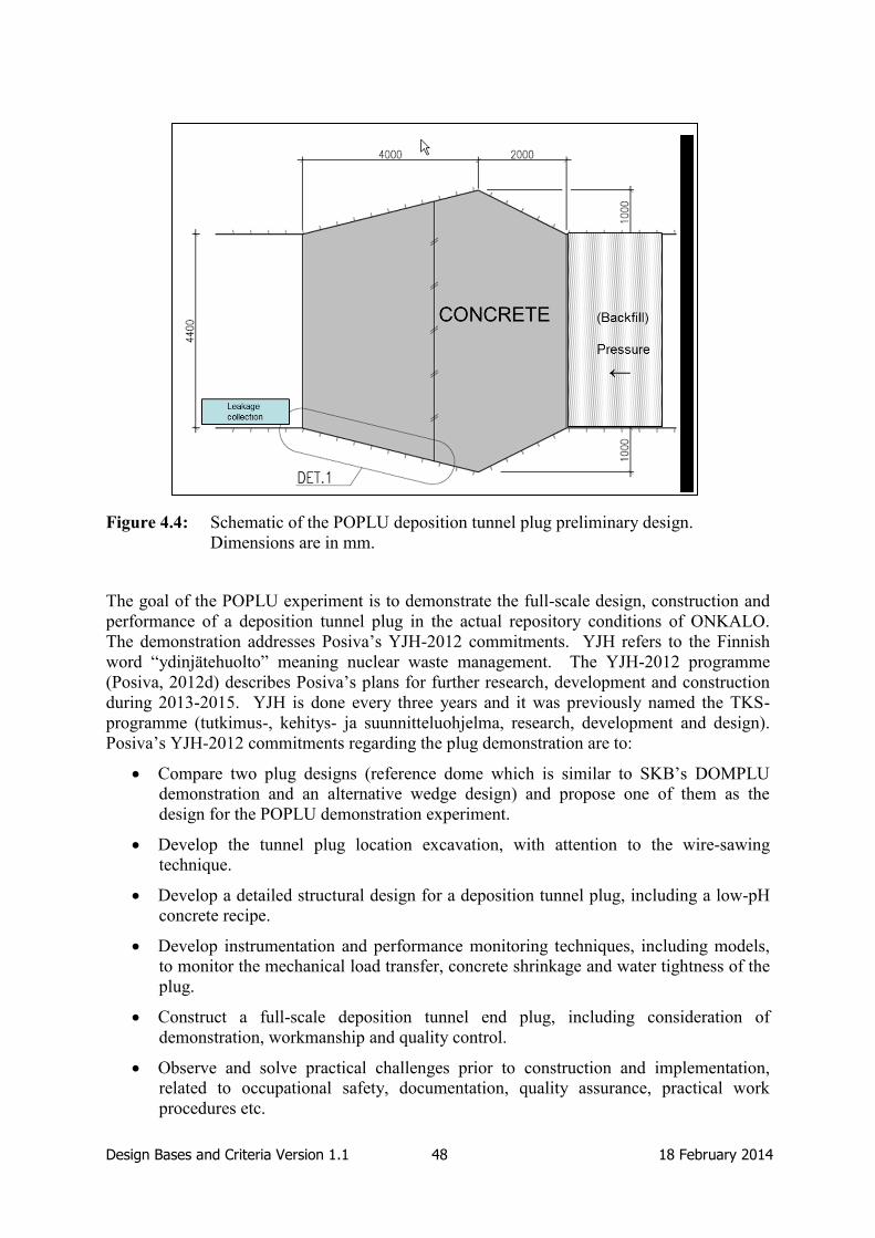
Design Bases and Criteria Version 1.1 48 18 February 2014
Figure 4.4: Schematic of the POPLU deposition tunnel plug preliminary design.
Dimensions are in mm.
The goal of the POPLU experiment is to demonstrate the full-scale design, construction and
performance of a deposition tunnel plug in the actual repository conditions of ONKALO.
The demonstration addresses Posiva’s YJH-2012 commitments. YJH refers to the Finnish
word “ydinjätehuolto” meaning nuclear waste management. The YJH-2012 programme
(Posiva, 2012d) describes Posiva’s plans for further research, development and construction
during 2013-2015. YJH is done every three years and it was previously named the TKS-
programme (tutkimus-, kehitys- ja suunnitteluohjelma, research, development and design).
Posiva’s YJH-2012 commitments regarding the plug demonstration are to:
Compare two plug designs (reference dome which is similar to SKB’s DOMPLU
demonstration and an alternative wedge design) and propose one of them as the
design for the POPLU demonstration experiment.
Develop the tunnel plug location excavation, with attention to the wire-sawing
technique.
Develop a detailed structural design for a deposition tunnel plug, including a low-pH
concrete recipe.
Develop instrumentation and performance monitoring techniques, including models,
to monitor the mechanical load transfer, concrete shrinkage and water tightness of the
plug.
Construct a full-scale deposition tunnel end plug, including consideration of
demonstration, workmanship and quality control.
Observe and solve practical challenges prior to construction and implementation,
related to occupational safety, documentation, quality assurance, practical work
procedures etc.

Design Bases and Criteria Version 1.1 49 18 February 2014
Produce a quality manual for quality control practices and risk mitigation during plug
construction.
All these aspects are regarded in the POPLU construction by means of material and
construction method selections. The safety functions of the POPLU plug are the same as
those defined for the reference design, because the design is made to comply with the
requirements in VAHA. The VAHA requirements applicable to POPLU are indicated in
Table 4.1. Although the design basis is in principle the same as for the reference deposition
tunnel plug, there are some significant differences because POPLU is an experiment rather
than an implementation of the reference design:
A larger range and quantity of stray materials will be allowed for POPLU than in the
actual plug in the repository. These materials can be recovered during the dismantling
of POPLU.
The use of sensors and wires for monitoring will be allowed, however no monitoring
sensors are foreseen in the final plug design.
In the planned repository, there will be two variations for deposition tunnel heights
depending on the origin of the spent fuel being disposed. Therefore, two different
plug dimensions will be used in the actual repository.
In addition, part of the design basis of POPLU is to have a similar performance monitoring
programme and pressurisation approach as DOMPLU.
The 2009 study of different plug concepts for deposition tunnels (Haaramo and Lehtonen,
2009) specified some general and detailed requirements for deposition tunnel plugs using
wedge-based structures. These requirements have been used as a basis for developing the
current design basis for POPLU, which is presented in Table 4.2. This table lists the
requirements from Haaramo and Lehtonen (2009) with comments made against each
requirement regarding similar requirements already existing in VAHA or the need for the
requirement to be considered in developing the detailed design criteria for POPLU. Note that
there are some requirements in Table 4.2 that did not originate from Haaramo and Lehtonen
(2009) but were considered to be important to include in POPLU. These are given in the last
group of the table.

Design Bases and Criteria Version 1.1 50 18 February 2014
Table 4.1: Levels 3 to 5 requirements of the VAHA system for the reference deposition
tunnel plugs. Links of each requirement to previous levels in VAHA are also
noted. The requirements from the reference plugs that are applicable to
POPLU are also indicated.
ID Requirement
Link to
previous
level in
VAHA
Applicable
in
POPLU?
Level 3 – Subsystem requirements for deposition tunnel plug
L3-BAC-2
The sealing structures of the deposition tunnels
consist of backfill and plugs. Backfill is the
material or materials that is/are used for
backfilling the deposition tunnels. Plugs will be
placed at the mouths of the deposition tunnels.
The purpose of the backfill is to keep the buffer
in place, maintain favourable and predictable
conditions for the buffer and the canister, and
also favourable rock mechanical, hydrological
and geochemical conditions in the near-field and
to retard the transport of radionuclides if the
canister starts leaking.
L2-SYS-1 No
L3-BAC-5
Unless otherwise stated, the backfill and plugs
shall fulfil the performance targets listed below
over hundreds of thousands of years in the
expected repository conditions except for
incidental deviations.
L2-SYS-4
L2-SYS-5 No
L3-BAC-9
The plugs shall isolate the deposition tunnels
hydraulically during the operational phase of the
repository.
L2-SYS-3 Yes
L3-BAC-13
The chemical composition of the backfill and
plugs shall not jeopardise the performance of the
buffer, canister or bedrock.
L2-SYS-3 Yes
L3-BAC-18 The plugs shall keep the backfill in place during
the operational phase. L2-SYS-3 Yes
Level 4 – Design requirements for deposition tunnel plug
L4-BAC-2
The main component of the backfill material
shall consist of natural swelling clays. The plugs
shall consist of materials that have a good
hydraulic isolation capacity and that will not
undergo large volume changes in the long term.
L3-BAC-2 Yes
L4-BAC-6
The plugs shall be designed to maintain their
hydraulic isolation capacity at least as long as
the central tunnels are open.
L3-BAC-9 Yes

Design Bases and Criteria Version 1.1 51 18 February 2014
ID Requirement
Link to
previous
level in
VAHA
Applicable
in
POPLU?
L4-BAC-13
The plug shall be designed to withstand the sum
of the swelling pressure of the backfill and the
hydrostatic pressure of the groundwater at the
repository depth.
L3-BAC-18 Yes
L4-BAC-14
The plugs must be designed to maintain a
backfilling function even after their hydraulic
isolation capacity has been lost.
L3-BAC-8 Yes
L4-BAC-18
Backfill and plug materials shall be selected so
as to limit the contents of harmful substances
(organics, oxidising compounds, sulphur, and
nitrogen compounds) and microbial activity.
L3-BAC-13 Yes
Level 5 – Design specifications for deposition tunnel plugs
L5-BAC-17
The plug shall consist of concrete dome,
bentonite seal and a filter layer. The thickness of
the sealing and filter layers is 750 mm. The
thickness of the concrete dome is 1500 mm
measured from the centre of the plug.
L4-BAC-13 No
L5-BAC-18
The concrete shall be water tight after
installation. The hydraulic conductivity of the
concrete mass shall be <1x10-11
m/s.
L4-BAC-2
L4-BAC-13 Yes
L5-BAC-19
The bentonite seal shall consist of bentonite with
montmorillonite content of 75-90%. In order to
ensure sufficient sealing capacity the dry density
shall be >1400 kg/m3. The sealing layer shall be
pre-saturated to ensure water tightness after
installation of the plug.
L4-BAC-13 Yet to be
decided
L5-BAC-20
The filter layer shall consist of sand or crushed
rock with grain size distribution optimized for
filtering.
L4-BAC-6 Yet to be
decided
L5-BAC-21 The plug shall maintain its hydraulic isolation
capacity for at least 100 years. L4-BAC-6 Yes
L5-BAC-27
The cementitious materials that are used in plugs
shall have a calcium to silica mass ratio less than
1:6.
L4-BAC-18 Yes
L5-BAC-28 The organics content in the plug shall be lower
than 1 wt-%. L4-BAC-18 Yes
L5-BAC-29
The total sulphur content in the plug shall be less
than 1 wt-%, with sulphides making, at most,
half of this.
L4-BAC-18 Yes

Design Bases and Criteria Version 1.1 52 18 February 2014
ID Requirement
Link to
previous
level in
VAHA
Applicable
in
POPLU?
L5-BAC-31
The mechanical strength of the plugs shall
correspond to a pressure load of at least 7.5 MPa
including the ambient hydrostatic pressure.
L4-BAC-13 Yes
L5-BAC-32 The main material component in the plug shall
be quartz sand or crushed rock. L4-BAC-14 Yes
Level 5 – Design specifications for host rock (related to plug siting in the tunnel section)
L5-ROC-50
The distance between the plug and the centre of
the first deposition hole shall be at least 5 m in
order to limit solute transport.
- No
L5-ROC-58 EDZ shall not be continuous along the plug
length. - Yes
L5-ROC-59 The plug location shall not be intersected by the
respect volumes of hydrogeological zones. - Yes
L5-ROC-60 The plug location shall not be intersected by the
respect volumes of brittle deformation zones. - Yes
L5-ROC-80 Hydraulically conductive fractures shall not
intersect the entire length of the plug. - Yes

Design Bases and Criteria Version 1.1 53 18 February 2014
Table 4.2: Plug requirements applicable to POPLU based on Haaramo and Lehtonen
(2009).
Requirement Comment
General requirements
A sealing structure is needed to keep the backfill in place
in the deposition tunnel.
Represented by L3-BAC-18 in
VAHA.
Water flow from the deposition tunnel to the central
tunnel must be minimal.
Represented by L3-BAC-9 in
VAHA.
Working in the central tunnel must be safe. Represented by L3-BAC-9 and
L3-BAC-18 in VAHA.
A deposition tunnel plug must close the deposition tunnel
as quickly as possible.
Represented by L3-BAC-9 and
L3-BAC-18 in VAHA.
Requirements for plug design
The primary tasks of the plug are to separate the
deposition tunnel from the central tunnel during the
operational period, and to resist the pressure of backfill
and water from the deposition tunnel.
Represented by L4-BAC-13 in
VAHA.
The plug structure shall prevent the backfill in the
deposition tunnel from loosening and swelling into the
central tunnel.
Represented by L3-BAC-18 in
VAHA.
The deposition tunnel plug shall prevent water flow out
of the deposition tunnel.
Represented by L3-BAC-9 in
VAHA.
Water tightness will be secured by using a high quality
plug material and by an adequate thickness of the
structure.
Although water tightness is not
explicitly stated in VAHA, this
requirement could be represented
by L4-BAC-2 "plugs shall
consists of materials that have a
good isolation capacity" and L4-
BAC-6 "the plugs shall be
designed to maintain their
hydraulic isolation capacity".
The plug structure is planned to be watertight to prevent
any major inflow through the plug structure or through
the contact between the rock sidewall and the plug.
Represented by L3-BAC-9 in
VAHA.
The plug will be in contact with the host rock. No match in VAHA – but there is
a requirement for the backfill L4-
BAC-29 that states that the
backfill must be in good contact
with the host rock. For the plug
this requirement has been
handled by injection grouting.

Design Bases and Criteria Version 1.1 54 18 February 2014
Requirement Comment
The pressure load on the plug will be transmitted to the
host rock through the plug/rock interface.
No match in VAHA (however,
this is represented to some extent
by L4-BAC-13) – could be added
as a Level 5 requirement on
POPLU.
Leachates from the plugs shall not significantly impair
the performance of the barriers.
Represented by L4-BAC-18 in
VAHA.
The use of organic materials is to be minimized. Represented by L4-BAC-18 in
VAHA.
The life cycle basis of the plug is the lifetime of the
operational period.
Represented by L3-BAC-9 and
L3-BAC-18 in VAHA.
Olkiluoto-specific design specifications and requirements
The plug structure shall be located sufficiently far away
from the central tunnel so that the loads from the backfill
on the plug do not extend to the central tunnel.
No match in VAHA – could be
added to the host rock
specifications related to plug
siting. There would also be a
Level 5 requirement specifying
the distance.
Hydrostatic pressure has been assumed to reach 4.5 MPa. Represented by L5-BAC-31 in
VAHA.
The elevated temperatures will cause an increase in the
stress in the surrounding rock and the stress will also
propagate to the backfill and to the plug structure.
No match in VAHA - could be
added as a Level 4 requirement
on POPLU. The experiment
accounts for this but POPLU is
not required to implement this
requirement. Vertical pressure on
the plug from the rock is
estimated at 13MPa, due to
thermal stresses.
A swelling pressure of 3 MPa has been used as input
data. In other words, a total of 7.5 MPa is used as the
dimensioning pressure.
Represented by L5-BAC-31 in
VAHA.
The estimated natural temperature in the Olkiluoto
bedrock is 12-13°C at a depth of 430 m.
No match in VAHA - could be
added as a Level 4 requirement
on POPLU.
The design of the plug shall assume that the operational
period temperature is 20°C.
No match in VAHA - could be
added as a Level 5 requirement
on POPLU. Note that this
requirement is included to
indicate a reasonable temperature
and is tentative.

Design Bases and Criteria Version 1.1 55 18 February 2014
Requirement Comment
A groundwater chloride content of 0-3% in the
environment of the repository is used as input data.
Represented by an existing
requirement (L5-ROC-19) in
VAHA, which states Chemical
composition of groundwater at
the repository level must be
within the limits set by the target
properties.
6<pH<11
Cl-<2 M
Total charge equivalent of
cations, Σq[Mq+]*, > 4E-3 M.
* [Mq+] = molar concentration
of cations, q = charge number of
ion.
The plug will be built in a location, where rock is of good
quality and intact.
Represented by L5-ROC,
L5-ROC-58, L5-ROC-59,
L5-ROC-60 and L5-ROC-80 in
VAHA.
EDZ has to be removed from the slot location of the plug. Represented by L5-ROC-58 in
VAHA.
Additional requirement for wedge plug not derived from Haaramo and Lehtonen (2009)
As far as is possible, the monitoring system shall be used
to acquire the same monitoring information as acquired
for the DOMPLU experiment, e.g. the same parameters,
monitored at the same spatial distribution and with the
same frequency.
This requirement has been set to
allow the results of the
demonstration experiments to be
compared.
As far as is possible, the pressurisation of the POPLU
experiment shall be the same as for the DOMPLU
experiment.
This requirement has been set to
allow the results of the
demonstration experiments to be
compared.
The temperature during operations shall be the natural
temperature.
Could be added as a Level 4
requirement on POPLU.
The heat generated from the hardening reaction of
concrete shall be assumed to be small.
Could be added as a Level 4
requirement on POPLU.
The reinforcement in concrete shall withstand the local
groundwater environment conditions for at least 100
years.
Could be added as a Level 4
requirement on POPLU. This
requirement is related to
L5-BAC-21.

Design Bases and Criteria Version 1.1 56 18 February 2014
Requirement Comment
Contact grouting shall be performed to ensure the water
tightness of the plug
Could be added as a Level 5
requirement on POPLU. This
requirement is related to the
requirement in Haaramo and
Lehtonen (2009) that the plug
will be in contact with the host
rock.
The plug shall consist of a wedge-shaped concrete
structure, reinforcement, and any material used for
contact grouting
Could be added as a Level 5
requirement on POPLU.

Design Bases and Criteria Version 1.1 57 18 February 2014
5. EPSP Design Basis (SÚRAO/CTU)
EPSP is a full-scale experiment of a tunnel plug being carried out in the Josef URL. This
section describes the process by which the design bases for tunnel plugs and for the EPSP
experiment have been developed in the Czech Republic, and describes the design basis for
both the reference plug in SÚRAO’s repository concept and for EPSP.
5.1 Process used by SÚRAO to Develop the Design Basis
5.1.1 Definition of the Design Basis and Method used to Describe the Design Basis
As noted in Section 2.2.3, the Czech geological disposal programme is currently in a generic
phase, with the status being reported in the 2011 KBS-3H study (SÚRAO, 2011). The 2011
KBS-3H study was undertaken at a conceptual level and does not include detailed designs.
The documents include identification of high-level requirements such as the amount of waste
to be disposed of, the performance of the safety concept and identification of the basic
components of the technical design, but they do not present detailed requirements.
The high-level requirements identified by SÚRAO to date have been derived from mining
law, atomic law, from internal assessment, and from collaborative work with SKB and
Posiva. This work has noted the benefit of adopting a structured approach to development of
the design basis at an early stage in the programme and the need to manage potentially
conflicting requirements from different regulatory documents.
5.1.2 Development of the Design Basis
The Czech plug design basis has been developed from experience gained through installation
of the plugs at the Háje gas storage facility (Hilar and Pruška, 2011) (see Appendix B).
Experience from other organisations (e.g. SKB and Posiva) has also been used to develop the
plug design.
5.2 Design Basis for the Reference Plug
Consistent with the conceptual approach taken in the 2011 KBS-3H study, the design basis
for the deposition tunnel plug in the repository concept is not highly-developed and specific
requirements on the reference plug are yet to be specified. A simple concrete plug was
adopted for the reference conceptual design and this structure was not represented in the post-
closure safety case. Therefore, no table of requirements on the reference design is provided.
5.3 EPSP Design Basis and Link to Design Basis of Reference Design
The EPSP experiment is the first time that SÚRAO has carried out any detailed work on
plugs and seals. The key objectives of the experiment are to test materials and technology
(including technology that may become part of the experiment), extending laboratory
experience to the underground environment and to full-scale, and to build the practical
expertise of the SÚRAO personnel. Implementation of the reference design itself is not being
tested. However, EPSP will also provide an important test-bed in developing a final plug
design and procedure for implementation.
The conceptual design for EPSP includes the following components (Figure 5.1):
Pressure Chamber: The pressure chamber is an open area that can be used to
pressurise the inner concrete plug. The chamber contains an inlet valve and a drain
valve that can be used to fill the chamber with air (gas), water or a bentonite slurry.

Design Bases and Criteria Version 1.1 58 18 February 2014
The chamber will be as small as possible to allow the pressure to be readily
controlled. The pressure chamber will be sealed with a membrane.
Concrete Walls: Concrete walls will be used to facilitate construction of EPSP.
Three concrete walls will be built: one between the pressure chamber and the inner
concrete plug, one between the bentonite and the filter, and one between the filter and
the outer concrete plug.
Inner Concrete Plug: The inner concrete plug will be one of the sealing components
in EPSP and will be constructed of sprayed fibre concrete. It is anticipated that there
will be no need for contact grouting of the plug, but this will be determined by
measurements during the experiment. The fibre concrete will be of relatively low pH,
although the recipe and pH values are to be determined during the detailed design
stage.
Sprayed Bentonite Pellets: The bentonite pellet zone will be comprised of B75
bentonite, a natural, high-smectite content Ca-Mg bentonite with a notably high iron
content in the octahedral layer of the smectite. The purpose of the bentonite is to seal
and absorb/adsorb any water that leaks across the inner concrete plug. The bentonite
zone will be 2-m long.
Filter: The filter will collect any water that is not absorbed by the bentonite. This is
most likely to occur if the leakage rate across the inner concrete plug is sufficient for
piping and erosion of the bentonite to occur. The filter may also be used to reverse
the direction of pressurisation of EPSP.
Outer Concrete Wall: The outer concrete plug is designed to hold the other
components of EPSP in place. However, should the direction of pressurisation of
EPSP be reversed, the outer concrete plug will have to perform as well as the inner
concrete plug, and, therefore, the requirements on the outer concrete plug are the same
as the requirements on the inner concrete plug.
A pressure test will be carried out on the inner concrete plug before bentonite is emplaced to
test the quality of this plug and to decide, after inspection, whether grouting around the plug
is required. This initial pressurisation will be carried out using air and water.
The design basis of the EPSP is flexible in order to allow the contractor responsible for
implementation to respond to experience gained throughout the experiment. Specific issues
for investigation are related to requirements such as achievement of target bentonite density,
concrete quality (lack of voidage, homogeneity), strength, shrinkage and absence of cracking,
and how these can be demonstrated. The experiment must also be carried out in a manner
that complies with national mining and environmental safety regulations. The design basis
for EPSP is captured in Table 5.1.

Design Bases and Criteria Version 1.1 59 18 February 2014
Figure 5.1: Schematic of the EPSP conceptual design. Dimensions are in mm.
The other significant requirements on the test plug are:
The strength of EPSP shall be consistent with withstanding a pressure of 7 MPa to
simulate the maximum pressure expected to be developed by the bentonite buffer in
the deposition tunnels.
The temperature in the concrete plugs during the cement curing shall be controlled in
order to limit shrinkage and crack formation.
The design life of the components of EPSP is 150 years, as the reference deposition
tunnel plugs must function through the operational period of the repository.
The bentonite zone shall use Czech bentonite (Bentonite B75) as this is the candidate
buffer material in the reference concept.
A concrete recipe with a relatively low pH shall be used for all the concrete and
shotcrete components to develop further understanding of these materials.
Fibre shotcrete shall be used for the inner and outer concrete plugs to limit crack
formation and to improve the strength of these structures without using pre-placed
reinforcing.

Design Bases and Criteria Version 1.1 60 18 February 2014
Table 5.1: Design basis for the EPSP experiment. Comments are provided where
additional context or explanation of the requirement is available.
Component Requirements Comment
Whole System
General
Requirements
EPSP shall be an experiment at
full-scale and of interactions
between materials.
It is expected that the experiment
will provide data and performance
understanding that can feed into the
development of safety functions for
the repository safety assessment.
Construction of the plug
components at full-scale will allow
testing of emplacement methods, in
particular whether the required
conditions be achieved.
The experiment shall contribute
to understanding of bentonite
saturation in response to leakage
through the inner concrete plug.
Materials
Materials used in EPSP shall be
well known and have been
investigated in the laboratory.
Technology
including
feasibility
Safety regulations for the mining
environment shall be followed.
This requirement imposes
restrictions on working practices.
Pressurisation
System
The pressurisation of the
experiment shall proceed so that
the piping in the bentonite is
controlled.

Design Bases and Criteria Version 1.1 61 18 February 2014
Component Requirements Comment
Pressurisation
regime
Pressurisation regimes in each
component of the plug shall be
flexible so as to respond to the
actual results of the method.
The main requirements for the
pressure regime are for the testing
procedures rather than on the plug
itself.
It is not expected that full saturation
of the bentonite by natural means
during the experiment, but any
forced saturation must be
undertaken such that it does not
induce failure of the plug.
Responses that might require a drop
in pressure in the pressure chamber
include leakages through the
concrete of the inner concrete plug
or leakage around the contact
between the plug and the rock.
Components - inside to outside
Pressure chamber
The volume of the pressure
chamber should be minimised as
this reduces the requirements on
pressurising the air and water
during the tests.
This is guidance not a mandatory
requirement.
The pressure chamber shall be
isolated from the host rock by
sprayed isolation membrane.
Pressurisation
pipes (inlet/drain
valves)
There shall be a back-up system
in case of failure (e.g. blocking
and rupture).
A system comprises one pair of
valves. The valves bodies are
external to the chamber.
Pressurisation pipes shall be
suitable for air, water and
bentonite slurry.
The pressurisation pipes shall be
exchangeable, i.e. both pipes
shall be suitable for use as an
inlet and an outlet.
The pipes shall be specified to
meet pressure requirements for
the experimental method.
There are no requirements on the
rate of filling/draining of the
pressure chamber.

Design Bases and Criteria Version 1.1 62 18 February 2014
Component Requirements Comment
Wall between
pressure chamber
and the inner
concrete plug
The wall shall be stable enough
to withstand shotcrete delivery.
The wall provides a base for the
concrete and formwork. The
supplier will calculate the
requirements in detail as they
depend on the shotcreting method.
The wall shall be constructed of
reduced pH concrete, as for the
shotcrete.
The pH of the concrete has not yet
specified. The pH is expected to be
below 12, but recipes are still being
tested.
It will have to be demonstrated that
the concrete develops a low pH, but
tests have not yet confirmed
performance.
Collaboration with the commercial
supplier of the concrete will be
used to develop the final material.
It is not yet possible to specify the
exact pH for the leachate or the
time at which this will apply for
these reasons.
The wall shall be sufficiently
permeable to transmit
fluid/pressure from the pressure
chamber to the inner concrete
plug.
Inner concrete
plug
The shape of the inner concrete
plug shall be symmetrical to
allow for loading from both
sides.
The shape is based on preliminary
static analyses and is the simplest
shape that fulfils the role. The
supplier will confirm this.
The inner concrete plug shall be
constructed with glass fibre
concrete.
Testing of glass fibre concrete is a
specific objective of the EPSP
experiment.
There shall be no unfilled spaces
within the volume of the inner
concrete plug.
This is difficult to test and depends
on control of the application of the
shotcrete, which, in turn, depends
on the expertise of the operator.
Spraying of the shotcrete shall
follow international standards.
Spraying of the shotcrete shall
follow Czech national quality
requirements.

Design Bases and Criteria Version 1.1 63 18 February 2014
Component Requirements Comment
The fibre concentration shall be
based on a shrinkage calculation.
The fibre composition is at the
discretion of the supplier.
Laboratory tests will be carried out
once the fibre compositions are
decided. Use of more than one
type/thickness of fibre is possible.
The fibre concentration determined
from the shrinkage calculation is
also to be tested for mechanical
strength (see next requirement).
The fibre concentration shall be
based on the static analyses that
include the geometry of the plug
e.g. the notches for the
abutment.
The strength of the concrete
shall be sufficient to withstand a
maximum applied pressure of
7MPa.
The design of the shotcrete
emplacement process shall
consider approaches that help to
avoid contact grouting.
The design of the inner concrete
plug shall take into account the
maximum crack aperture that
will be defined at a later stage.
The shrinkage calculation will be
used as an input to derive the
maximum acceptable crack
aperture.
There shall be no continuous
cracks through the inner
concrete plug.
The fibres in the shotcrete shall
be evenly distributed.
The temperature of the concrete
shall be controlled in order to
avoid crack formation.
The evolution of the temperature
distribution in the concrete shall
be monitored so that
understanding of curing
temperatures will be further
developed.

Design Bases and Criteria Version 1.1 64 18 February 2014
Component Requirements Comment
The response to any excessive
leakage around the plug could
include grouting around the
contact.
Sprayed bentonite
pellets
The bentonite pellets shall be
composed of bentonite sensu
stricto.
Montmorillonite clays are not
acceptable for use in the
experiment.
The bentonite shall be the B75
type.
It is intended to investigate the
performance of this bentonite,
which may behave somewhat
differently to other bentonites
owing to its composition.
The manufacturer can supply this
bentonite in sufficient quantities.
The bentonite shall be a
homogeneous product.
An industrial product is required to
ensure homogeneity over a large
amount of material.
The bentonite shall be a natural
bentonite (not activated).
This requirement is because there is
insufficient confidence in the long-
term performance of activated
bentonites.
The bentonite shall contain a
sufficient proportion of smectite
to provide the desired swelling
pressure and hydraulic
conductivity at the specified
density.
The bentonite shall contain only
limited amounts of other mineral
phases (quartz, carbonates,
zeolites, feldspars etc.).
The emplaced bentonite shall
achieve a density of 1.4 Mgm-3
.
The density is specified to achieve
a swelling pressure of 2 MPa and a
hydraulic conductivity of
10-12
ms-1
.
The bentonite emplacement
technique shall be disclosed.
The technique used for
emplacement of the pellets is to be
decided by the supplier - but the
process must be disclosed to
SÚRAO so that it can be used in
future experiments if required.

Design Bases and Criteria Version 1.1 65 18 February 2014
Component Requirements Comment
The density of the emplaced
bentonite shall be confirmed by
frequent sampling and testing
according to a schedule for
testing.
A plan for testing the bentonite
density shall be developed and
agreed with SÚRAO ahead of
installation of the bentonite
layer.
The thickness of the bentonite
layer shall be 2m.
The bentonite thickness is
determined by the position of the
second concrete wall that retains it
during emplacement.
The bentonite shall be monitored
for pore pressure during the
experiment.
The monitoring of pore pressure
shall be sufficient to allow
estimation of the bentonite
saturation.
The desired condition is that the
bentonite will take up all of the
water leaking through the inner
concrete plug, although it is
recognised that there is a significant
probability that water this condition
will not be met (there may be
piping and erosion of the bentonite
and flow of water into the filter).
Concrete wall
between bentonite
and filter
The concrete wall shall be raised
at the same rate as the bentonite
is emplaced.
Filter
The filter shall collect any water
leaking through the bentonite.
The material of the filter shall be
highly permeable.
The material of the filter shall be
inert.
Water in the filter shall be
collected at the bottom of the
filter and drained through the
outer concrete wall.

Design Bases and Criteria Version 1.1 66 18 February 2014
Component Requirements Comment
The filter shall be implemented
so that it can be pressurised in a
similar way to the pressure
chamber.
In the normal state, there is no
requirement for pressurising the
filter. However, this requirement
makes it possible to reverse the
direction of pressurisation in EPSP
in the future if so desired.
Water flow into the filter shall
be monitored.
The design of the collection pipe
in the filter should be such as to
ensure that is not blocked by the
filter material.
Concrete wall
between the filter
and the outer
concrete plug
Same requirement as for the first
concrete wall.
Outer concrete
plug
Requirements the same as for
the inner concrete plug.
Host rock
The quality of the host rock shall
be improved (by grouting) to
ensure there is no reactivation of
features in response to
pressurisation.
There are no requirements on the
EDZ as the experiment is sited in
an existing excavation with an
existing EDZ. The grouting will
modify the EDZ conditions so that
the experiment will not fail owing
to rock displacements.
Grouting shall be required for
5 m around the EPSP niche to
reduce the hydraulic
conductivity and to allow
sufficient pressurisation of the
experiment.
Tests shall be undertaken to
verify the results of grouting.
The method for excavation of
the abutment notches shall avoid
formation of open fractures.

Design Bases and Criteria Version 1.1 67 18 February 2014
Component Requirements Comment
There shall be a good knowledge
of the rock conditions before the
rock grouting is carried out.
The host rock is a granodiorite,
whereas the host rocks under
consideration for the repository are
either granites or metamorphic
rocks. There are, therefore,
differences in mineralogy but these
will not affect conduct of the
experiment.
There shall be a good knowledge
of the rock conditions after the
rock grouting is carried out and
before the experiment is
constructed.

Design Bases and Criteria Version 1.1 68 18 February 2014
6. FSS Design Basis (Andra)
FSS is a full-scale experiment of a drift and ILW disposal vault seal being carried out in a
warehouse of a surface facility in St Dizier, which is close to the French URL at Bure. This
section describes the process by which the design basis for the reference drift and ILW
disposal vault seal, and the FSS experiment have been developed, and describes the design
basis for both the reference drift and ILW disposal vault seal in Andra’s repository concept
and for FSS.
6.1 Process used by Andra to Develop the Design Basis
6.1.1 Definition of the Design Basis and Method used to Describe the Design Basis
The safety objectives for the Cigéo are defined in the safety guide produced by the French
Nuclear Safety Authority (ASN) (ASN, 2008). In order to meet these safety objectives,
Andra assigns safety functions to all repository components that have a significant role in
providing safety, including the host formation, the waste packages and the EBS. Each safety
function can then be broken down into sub-functions, to a level of detail that the designer
considers sufficient – this process is termed ‘functional analysis’ (Andra, 2005). The
functional analysis outputs are used to develop the more detailed technical specifications and
design requirements on each repository component.
After defining the safety functions (and any sub-functions) required for a certain repository
component, the design specifications are developed. For seals, the designer asks the
following questions to help develop the specifications from the safety functions:
What is the required performance of the seal? (Based on various performance
evaluations).
What is the phenomenological environment? (Thermal, hydraulic, chemical and
mechanical contexts).
What influence do the design elements have on hydraulic performance? (Reasonable
objectives considering technical feasibility and demonstration capacity).
After developing the design requirements and specifications, an iterative process is used to
update and develop these design specifications and requirements further as more knowledge
is acquired (e.g. scientific knowledge on the host rock and repository materials, and
knowledge gained through design studies), and a more detailed understanding of the post-
closure performance is gained through conducting safety assessments and demonstrator
experiments. The high-level safety functions are kept unchanged throughout the process,
whereas the sub-functions and design specifications or requirements evolve over time as
knowledge is gained through performance assessment and research activities. As a
consequence, sub-functions and design specifications will become more detailed and specific
through time. The iterative process used to update the design basis is illustrated in Figure
6.1.

Design Bases and Criteria Version 1.1 69 18 February 2014
Many divisions within Andra are responsible for maintaining the definitions and traceability
of specifications. The Program Division co-ordinates this work in close collaboration with:
The Risk Assessment Division: this division develops safety principles, and
operational and post-closure safety assessments.
The Research and Development Division: this division develops scientific and
technological knowledge, in particular scientific knowledge on the long-term
behaviour of the repository system.
The Engineering and Cigéo Project Division: this division develops the approach to
industrial implementation of disposal, in particular development of engineering
materials used in designs.
Regular meetings are organised between these divisions to discuss and assess the work
carried out and its results, to identify potential issues, to verify compliance of designs with
requirements, and to propose modifications to the requirements and design basis in order to
support a demonstration of safety. There is no formalised process for change management of
requirements in Andra’s programme. The meetings (and the related minutes) with the
different divisions are seen as a way of providing a critical approach to what has been
achieved and carrying out a gap analysis.
Discussions between Andra and ASN, with its scientific and technical expert support
organisation (IRSN), and between Andra and the National Review Board (CNE) also
contribute to the development of the design basis.
Figure 6.1: Iterative process used to update the design basis in Andra’s concept.

Design Bases and Criteria Version 1.1 70 18 February 2014
With regard to the management of the design basis for the FSS experiment, the FSS design
and construction is contracted to a consortium of four companies (the GME consortium), and
the contract for the design and construction includes a set of technical specifications detailing
the requirements on the experiment. Andra’s experiment leader scrutinizes the results
obtained by the consortium at each step of the work and checks their compliance with the
pre-established requirements.
At the current stage of Andra’s programme, which is focused on developing a licence
application, specifications for the drift seal are intended to demonstrate the feasibility of
“reasonable” sealing performance. In this context, reasonable refers to a design that meets
current requirements; further research and development (R&D) (e.g. further tests, studies
and/or experiments related to seals phenomenology, and technical improvements in the seal
construction process) could be undertaken to improve the design and performance.
Specifications are intended to become increasingly more precise after consideration of
feedback from this R&D.
Two full-scale in situ demonstrators of drift seals will be constructed as soon as the first
disposal zone is commissioned in order to observe their behaviour during operation of the
repository (about 120 years). The purpose is to demonstrate the feasibility and performance
of drift seal design.
The term ‘design basis’ is not used by Andra in its programme. Andra does not employ a
systems engineering approach for the seal concept nor does it use structured databases
featuring hierarchies of requirements. However, the process that is used to define the
requirements and specifications on seal design is consistent with the approach used in other
programmes, as discussed in Section 8.
6.1.2 Development of the Design Basis
The drift and ILW disposal vault seal design basis has evolved through a series of design and
assessment cycles, including the Dossier 2001, the Dossier 2005 and an update to the safety
assessment in 2009. In the Dossier 2005, the design basis of drift seals included cut-offs for
the reference EDZ assumptions and basic concrete containment walls (see below). Since
2005, in situ and surface laboratory studies on hydraulic and hydro-mechanical behaviour of
the EDZ (i.e. fractured Callovo-Oxfordian clays) have shown that the maximum hydraulic
conductivity of the EDZ would be 10-9
m/s. In addition, studies on low-pH concrete showed
that chemical stability of clay core and mechanical wall of drift seals could be improved
through use of this type of concrete. This information has been used to refine the conceptual
design of seals as described below.
6.2 Design Basis for the Drift Seal Reference Design
Types of Seal in the Reference Repository Design
As noted in Section 2.2.4, three types of seal are envisaged in the French reference disposal
concept: shaft seals, ramp seals, and drift and ILW disposal vault seals. The conceptual
design for each type of seal is illustrated in Figure 6.2. Each seal consists of a swelling clay
core and two low-pH concrete containment walls. The swelling clay core provides the
required long-term performance of the seal (see below); whereas the containment walls are
included to mechanically contain the clay.
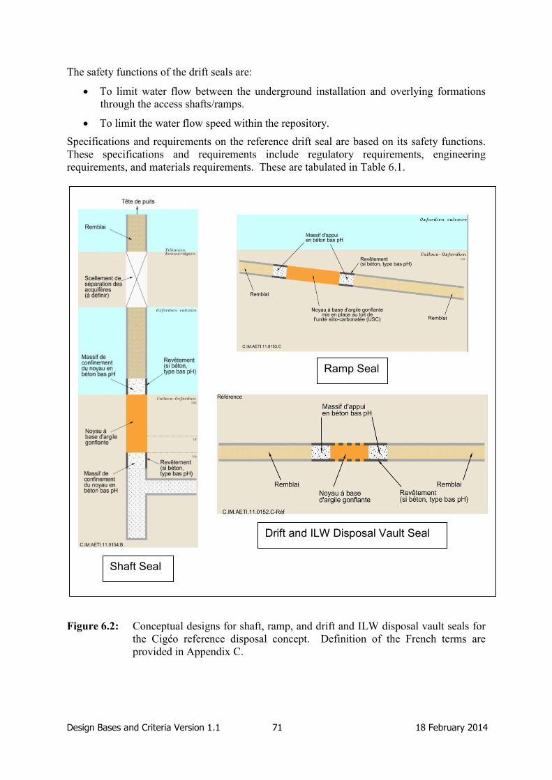
Design Bases and Criteria Version 1.1 71 18 February 2014
The safety functions of the drift seals are:
To limit water flow between the underground installation and overlying formations
through the access shafts/ramps.
To limit the water flow speed within the repository.
Specifications and requirements on the reference drift seal are based on its safety functions.
These specifications and requirements include regulatory requirements, engineering
requirements, and materials requirements. These are tabulated in Table 6.1.
Figure 6.2: Conceptual designs for shaft, ramp, and drift and ILW disposal vault seals for
the Cigéo reference disposal concept. Definition of the French terms are
provided in Appendix C.
Shaft Seal
Drift and ILW Disposal Vault Seal
Ramp Seal

Design Bases and Criteria Version 1.1 72 18 February 2014
The primary difference between the different types of seals is the extent to which the concrete
lining is removed before installation of the swelling clay core. Shaft and ramp seals will be
located in the upper part of the Callovo-Oxfordian Clay, which is more competent (this part
of the clay contains more carbonates) and, therefore, will generate less damage of the rock
during construction. As a consequence, removal of the lining prior to installation of the
swelling clay core can be considered as a reference; it ensures a good contact between the
clay core and the rock, and so a better hydraulic performance. For the drift and ILW disposal
vault seals only partial removal of the lining is envisaged as described below. Indeed, EDZ
around the openings leads to remain cautious towards seal construction operations security
(risk of rock fall with people at work).
Hydraulic Requirements
In addition to the water flux requirement, ASN guidelines include a general requirement on
the drift seal to play a major role in providing post-closure safety. This role is performed
jointly with the clay host formation. The limiting of the water flux therefore contributes also
to the primary safety functions “to limit radionuclide release and to immobilize radionuclides
within the repository” and “to delay and limit radionuclide migration”.
Performance assessment modelling by Andra has demonstrated that radionuclide migration
will be preferentially through the host rock provided the seals maintain a hydraulic
conductivity of 10-9
m/s or less. This hydraulic conductivity applies across the seal and must
therefore be met by all the components: the swelling clay core, any lining and the EDZ, and
also the interfaces between these elements. Tests in the Bure URL have confirmed that the
EDZ formed in the host rock in response to excavation will self-heal and the hydraulic
conductivity in this area will meet the 10-9
m/s target. This target can be met by the swelling
clay core through appropriate design. Concerning the interface between the lining and the
swelling clay core, and the lining and the host rock, Andra has decided that the lining, which
is required for repository operation, will be (at least partially) removed prior to installation of
the seals in order to meet the 10-9
m/s target.
For the drift and ILW disposal vault seals, the nature of the host rock is such that removal of
the lining is more difficult than for the shaft and ramp seals. However, calculations have
shown that only a few metres of the lining have to be removed for the seals to meet the
hydraulic conductivity target. In addition, geomechanical analysis has concluded that 1.5 m
lengths of tunnel support can be removed safely, and that the remaining lining would provide
sufficient support for operations.
Although the performance assessment modelling has shown that a hydraulic conductivity for
each element of the seal should be 10-9
m/s or less, the actual requirement for the swelling
clay core currently set in the Andra programme is 10-11
m/s. This is regarded as a realistically
achievable value, and the current testing programme is evaluating whether this target value
can indeed be met.
An alternative to the drift and ILW disposal vault seal reference conceptual design is also
under consideration by Andra. The alternative includes hydraulic cut-offs – 30-cm wide
recesses that would be filled with swelling clay and would intercept the EDZ (Figure 6.3).
This alternative is the conceptual design considered in the Dossier 2005, as discussed in
Section 6.1.2.

Design Bases and Criteria Version 1.1 73 18 February 2014
Figure 6.3: Alternative conceptual design for ramp, and drift and ILW disposal vault seals
that includes hydraulic cut-offs, here labelled as “groove filled with swelling
clay”.
Other Material and Performance Requirements
In addition to the material and performance requirements discussed above, additional
requirements are defined for the drift and ILW disposal vault seals:
To use low-pH concrete for mechanical containment walls that keep the clay-based
core in place and for any drift lining in contact or in close vicinity with the clay core.
This requirement implies that low-pH concrete is also required for the part of the
lining of the drift and ILW disposal vault seals that is not removed. This means that
the location of these seals should be pre-determined before the lining of the tunnels is
carried out (as it would be an unnecessary use of resources to use more expensive
low-pH concrete everywhere) or that, during construction of the seal, remaining parts
of lining should be replaced by low-pH lining. No pre-location is required for shaft or
ramp seals, where all of the lining is removed.
The drift seals are orientated parallel to the maximum principal stresses to minimise
the size and impact of the EDZ. This means that the drift seals in the HLW area of
the repository will be parallel to HLW disposal cells
In addition to long-term safety, the design basis also includes requirements on technical
feasibility. These include the requirement that the design allows partial or total removal of
the concrete support in the clay core emplacement, and the requirement that the design
permits the capability to assess and/or measure the required performance of the seal. ASN
also requires that the design of the drift seal is simple, demonstrable and measurable.

Design Bases and Criteria Version 1.1 74 18 February 2014
Requirements on the Swelling Clay Core
The swelling clay core part of the drift seal will be comprised of swelling clay pellets and/or
powder, and eventually shotclay. These materials are used to ensure a perfect filling of the
volume dedicated to the clay core, including any breakouts of the clay host rock (where lining
is removed). Design targets are specified including: no voids in the crown space of the drift,
the clay core must be homogeneous, there must be a good contact between the clay host rock
and clay core (and between the remaining lining parts and the clay core), and the dry density
of the bentonite must be defined in order to obtain a specified swelling pressure (target
value). The dry density value has not yet been fixed; its specification is one of the objectives
of the FSS experiment. The design basis does not define the type of clay material; material
type is considered by Andra to be part of the design.
Requirements on the Low-pH Concrete
The containment walls will be made of low-pH concrete:
To limit/avoid chemical interactions with swelling clay core and clay host rock, in
order to preserve their properties.
To ensure that the mechanical properties of the wall are maintained during the
expected period of repository saturation (including that of the swelling clay core).
To facilitate wall emplacement operations; the low-pH concrete will have a relatively
low heat output during curing, and it will be possible to limit internal fracturing and
shrinkage by using an appropriate low-pH recipe.
6.3 FSS Design Basis and Link to Design Basis of Reference Design
The FSS experiment is part of a wide-ranging programme of R&D and demonstrator
experiments that was established in response to the discussions with ASN and the French
National Assessment Board in 2009, during which it has been noted that seals, and in
particular drift and ILW disposal vault seals, require demonstration in order to achieve
licensing authorisation. As a result, R&D studies and demonstration experiments have been
launched to assess the technical feasibility and to develop the post-closure requirements of
seals in the repository.
The main objective of the FSS experiment is to develop confidence in, and to demonstrate,
the technical feasibility of constructing a full-scale drift or ILW disposal vault seal.
Technical feasibility includes demonstrating the ability of the approach used to emplace the
clay to be suitable for filling recesses in the clay host rock, i.e. breakouts generated during the
removal of the concrete support lining. The experiment is focused on the construction of the
seal, and the materials will not be saturated or otherwise pressurised. The conceptual design
of the FSS experiment is illustrated in Figure 6.4.

Design Bases and Criteria Version 1.1 75 18 February 2014
Figure 6.4: Conceptual design for the Andra FSS experiment.
Other tests being undertaken as part of the R&D and Demonstrator programme include tests
in the Bure URL and in surface facilities and laboratories:
In situ experiments at Bure URL include tests on the hydro-mechanical behaviour of
swelling clay-based and/or low-pH components: these include NSC (hydro-
mechanical performance of a drift seal), DCN (removal of tunnel lining segments),
TSS (hydro-mechanical performance of an EDZ cut-off) and BHN (hydro-mechanical
performance of the swelling clay core in contact with the host rock considering
natural saturation).
Mock up experiments at surface: In addition to the FSS experiment, the SET
demonstrator is focused on emplacement of swelling clay in a full scale hydraulic cut-
off, and the REM test is considering the performance of the reference drift seal. The
REM test will include development of understanding of the hydration of the seal
materials used in FSS, and an assessment of the hydro-mechanical response of
bentonite pellets to hydration, and is therefore considered as a sub-set of the FSS
experiment (i.e. it investigates the saturation of the swelling clay core, whereas FSS
does not include saturation). Complementary research and modelling will accompany
the experiments to investigate the chemical-mechanical coupling and the behaviour of
the seal in repository conditions.
An in situ ramp seal demonstrator and a drift seal demonstrator are planned for the
first construction phase of the repository (circa 2025).
Other objectives of the FSS experiment are to:
Demonstrate industrial feasibility and satisfactory emplacement of large volumes of
bentonite material and low-pH shotcrete and cast concrete.
Define the operational constraints, linked to emplacement activities, which are
compatible with the mechanical and hydraulic properties allocated to the seal
components.

Design Bases and Criteria Version 1.1 76 18 February 2014
Determine formulations of bentonitic materials and increase the knowledge about its
resaturation by natural fluxes (through the REM sub-experiment).
Determine formulations of cementitious materials.
Define construction methodologies and backfilling processes.
Define and implement the commissioning methods necessary to verify compliance of
the work to the specifications during emplacement operations.
Define and implement the commissioning methods necessary to verify compliance of
the work to the specifications after emplacement operations.
The main difference between the reference and FSS design bases for the Andra drift seal is
the length of the seal. The real seal underground will be longer than the seal considered in
FSS. The FSS experiment will investigate two types of low-pH containment wall (Figure
6.3); one pre-cast and one emplaced as shotcrete, to allow the preferred method to be selected
and incorporated into the reference concept.
Detailed specifications for the FSS experiment are compiled in Table 6.2. These have been
extracted from Andra (2012), which is the technical specification document produced by
Andra in the tendering process for the experiment. The specifications are divided into the
following topics:
Site of the experiment: this includes specifications on the facility where the
experiment is to be carried out.
Context of the experiment: the experiment will be carried out as if it were
implemented 500 m underground by taking account of underground construction
regulations, underground temperature and humidity, and the transfer distance and time
of materials.
The test box: this includes the dimensions of the test box and its components.
Upstream entrance hall: this is the space between the upstream face of the box and
the upstream containment wall. This area needs to be isolated from the outside
environment.
Upstream concrete containment wall: specifications on the dimensions of this wall
and the requirement on using low-pH concrete are prescribed here. This wall has no
hydraulic function.
Clay core: the dimensions of the core and the form of the breakout sections are given
in this section of the specification.
Downstream concrete support wall: the composition of the support wall of low-pH
concrete blocks is prescribed here. This wall has no hydraulic function. It is
progressively erected as the swelling clay core is emplaced.
Downstream concrete containment wall: specifications on the dimensions of this wall
and the requirement on using low-pH shotcrete are given here. This wall has no
hydraulic function.
Downstream entrance hall: this is the space between the downstream face of the box
and the downstream containment wall. This area needs to be isolated from the outside
environment.

Design Bases and Criteria Version 1.1 77 18 February 2014
Observation windows: these are openings to enable visual monitoring of the filling
operations inside the test box.
Equipment: any equipment used to monitor the temperature and relative humidity
inside the box should be installed outside the box. The two entrance halls can be used
for installation of monitoring equipment after the filling operations have been
completed.
Low-pH concrete: specifications on concrete formulations to be used, including use
of aggregates and other materials. The specification to have a pH of 10.5 to 11 at 28
days was found to be quite optimistic in the initial tests. This requirement should now
be fulfilled at 90 days.
Swelling clay: requirements on the swelling clay materials mainly specify a swelling
pressure and hydraulic conductivity to be achieved. These are 7 MPa and 10-11
m/s,
respectively. There is no requirement for a specific dry density value; however a
value will be specified during material testing. This dry density value will be
measured in the monitoring stage to ensure that the swelling pressure and hydraulic
conductivity requirements are met. Bentonite pellets of different sizes and powder
can be used in the swelling clay core.
Procedures for box filling: indications of the methods for filling the different sections
of the box (containment walls, clay core, etc.) are provided here. Particular attention
is given to the feasibility of filling the recesses to ensure adequate contact with the
box lining.
Dismantling: specifications regarding dismantling activities, including appropriate
disposal of any wastes generated during the experiment.
Compliance and monitoring: requirements on the methods and measures that need to
be in place in order to verify the compliance of the construction methods, the box
dimensions, the filling operations, and the concrete and clay formulations to the
specifications.
Quality of fillings: these are requirements to ensure that all filling operations are
adequate and adhere to the specifications. This includes making video recordings of
the operations and ensuring that the temperature and relative humidity inside the box
are appropriate.
Andra interventions: these are independent procedures that Andra envisages to
implement in order to ensure that specifications are followed (e.g. by doing
independent monitoring of the temperature and relative humidity inside the box, and
performing a scan of the box to confirm its initial volume).
Interface with Andra’s data acquisition system: the data collected by the installed
monitoring sensors will be transferred in real-time to ADNRA.
Interface with the REM experiment: the same filling materials used in FSS will be
used for the REM experiment box.
Arrangements for site visitors: these should take account of visitors from other
countries. Andra requires that all signs and safety manual are in French and English,
as well as the provision of safety helmets and shoes for visitors.

Design Bases and Criteria Version 1.1 78 18 February 2014
Table 6.1: Requirements on the seals in the French concept.
Requirement or
Specification Group
Requirement or Specification
Regulatory Requirements Seals shall limit the water flux through the repository after
closure.
Along with the clay host rock, seals shall play a major role in
repository safety.
Materials Requirements The seals shall include a swelling core comprised of a clay-
based material with a maximum overall hydraulic
conductivity of 10-11
m/s, swelling pressure close to but not
exceeding the effective mechanical stress of 7 MPa, and a
length of two diameters (or 20 m) at least.
The seals shall include low-pH containment walls and drift
lining in contact with the clay core to maintain the swelling
clay core and host rock properties in the long term.
All or part of the concrete support around the swelling clay
core shall be removable to achieve direct contact between the
swelling clay core and the clay host rock.
There shall be no voids in the crown space of the drift.
The clay core shall be homogeneous
There shall be a good contact between the clay host rock and
the clay core.
The dry density of the bentonite shall be determined in
laboratory tests in order to reach the specified swelling
pressure.
The drift seals shall be orientated parallel to the maximum
principal stresses to minimise the size and impact of the
EDZ.
The drift seals shall be located approximately 100 m or more
from the nearest disposal cell so that the temperature of the
seals shall not exceed 50 °C.
Feasibility Requirements The design shall be technically feasible, including partial or
total removal of the concrete support in the clay core
emplacement regions.
It shall be possible to assess/measure the performance of
seals and plugs.

Design Bases and Criteria Version 1.1 79 18 February 2014
Table 6.2: Requirements specific to the FSS experiment in addition to those defined in
Table 6.1.
Requirement or
Specification
Group
Requirement or Specification
Site of the
experiment
It is preferred that the FSS experiment is carried out in a surface
facility, although conducting the experiment in an underground
facility would be acceptable. The use of the Bure URL is excluded
for logistical reasons.
The chosen facility shall comply with all the technical specifications
of the experiment.
It is preferred that the FSS experiment is carried out in the vicinity of
the Bure URL.
Context of the
experiment
The FSS experiment shall be conducted as if it were undertaken 500
m underground with all regulatory requirements in this context
determined and applied accordingly.
The methods used to construct the FSS experiment shall be consistent
with working under the temperature and humidity conditions expected
500 m underground.
All constraints induced by the distance and means of transfer of
material from the surface to the underground galleries shall be applied
in the surface facility for the FSS experiment, notably the transfer of
concrete materials.
All necessary measures shall be taken to ensure that the regulations in
the “Code du Travail” are adhered to during the design of the
experiment, and implement them in the least penalising manner for
the experiment without endangering the safety of the people and
environment (the Code du Travail is the French Labour Code).
The test box
The test box shall have the following dimensions:
Internal diameter: 7.6 m.
Internal length: 35.5 m (minimum).
Concrete lining thickness: 0.7 m.
The interior finish of the box shall have random irregularities of
3-5 cm depth to represent the lining of the clay host rock wall in a real
repository gallery.
The test box shall have external features (recesses) up to 1 m from the
surface of its upper part as required by the experiment.
The test box shall be held firmly stable in place and its walls shall not
deform or experience displacements of more than 5 mm during the
filling operations.
The deformations and displacements of the box shall be measured at
regular intervals during the lifetime of the experiment.

Design Bases and Criteria Version 1.1 80 18 February 2014
Requirement or
Specification
Group
Requirement or Specification
The box can be constructed with ordinary concrete.
The parts of the box that simulate the parts of the conceptual design
where the concrete lining has been removed shall have a texture
similar to the clay host rock.
The test box shall consist of the following components:
An upstream entrance hall.
A section for installing the upstream low-pH cast concrete
containment wall.
A section for installing the swelling clay core.
A section for installing the downstream low-pH concrete
support wall blocks.
A section for installing the downstream low-pH shotcrete
containment wall.
A downstream entrance hall.
Observation windows and other equipment are also part of the box.
Upstream entrance
hall
The upstream entrance hall shall have a minimum length of 5 m to
allow for installation of equipment (e.g. core drilling machines).
The upstream entrance hall shall be isolated from the external
environment by a door which has minimum dimensions of: 4 m
(length) and 3 m (height). The door ensures that temperature and
humidity requirements during the filling of the box are met, and it also
provides a point of entry for checking equipment that may be installed
after filling operations have been completed.
Upstream concrete
containment wall
The upstream concrete containment wall shall be made of low-pH
concrete.
The upstream concrete containment wall shall have a length of 5 m.
The upstream concrete containment wall shall have a recess in its
upper part to simulate removal of the gallery lining, with the
following properties:
Length: 1.5 m (centred along the 5-m-long wall).
Depth: 0.3 m (beyond the concrete lining).
Extent: 60º either side of the vertical axis of the box.
Clay core
The swelling clay core shall have a length of 13.5 m.
The swelling clay core shall incorporate three zones (1, 2 and 3 from
the upstream side to the downstream side) simulating removal of
lining in the gallery and having breakout features.
The three zones shall be 1.5-m-long and 3-m-apart.
Zone 1 shall simulate concrete lining removal only.

Design Bases and Criteria Version 1.1 81 18 February 2014
Requirement or
Specification
Group
Requirement or Specification
Zone 2 shall simulate concrete lining removal, with a breakout recess
0.5 m to 1 m in depth (beyond the concrete lining) and placed 60º either side of the horizontal axis of the box.
Zone 3 shall simulate concrete lining removal, with a breakout recess
0.5 m to 1 m in depth (beyond the concrete lining) and placed 60º either side of the vertical axis of the box.
The filling of the clay core shall be done from the upstream side to the
downstream side (i.e. from zone 1 to zone 3).
Downstream
concrete support
wall
The concrete support wall shall consist of low-pH concrete blocks.
The length of the support wall is estimated at 2 m (subject to
confirmation during construction).
Downstream
concrete
containment wall
The downstream concrete wall shall be made of low-pH shotcrete.
The downstream concrete wall shall have a length of 5 m.
The downstream concrete wall shall have a recess in its upper part to
simulate removal of the gallery lining, with the following properties:
Length: 1.5 m (centred along the 5 m long wall).
Depth: 0.3 m (beyond the concrete lining).
Extent: all around the box.
Downstream
entrance hall
The downstream entrance hall shall have a minimum length of 5 m to
allow for installation of equipment (e.g. core drilling machines).
The downstream entrance hall shall be isolated from the external
environment through a door which has minimum dimensions of: 4 m
(length) and 3 m (height). The door ensures that temperature and
humidity requirements during the filling of the box are met, and it also
provides a point of entry for checking equipment that may be installed
after filling operations have been completed.
Observation
windows
The test box shall include windows allowing observation of filling
operations (e.g. at the crown of the gallery, at the recesses, and at the
area of contact between the low-pH concrete and the clay core).
It shall be possible to close the windows so as not to influence
operators during the filling phase.
The positions of these windows shall be agreed with Andra.
Equipment
The box design shall ensure a relative humidity (RH) between 50%
and 75% and a temperature between 18 and 30ºC before the start of
the filling operations until the end of the experiment.
All equipment necessary to guarantee the RH and temperature
conditions are met shall be installed outside the box, except for air
conditioning equipment that may be only temporarily required.

Design Bases and Criteria Version 1.1 82 18 February 2014
Requirement or
Specification
Group
Requirement or Specification
The installation of equipment in the upstream and downstream
entrance halls shall be limited in the post-filling phase to avoid
interfering with any control or monitoring operations envisaged.
Low-pH concrete
All concrete components inside the test box shall be of low-pH. The
box itself does not need to be of low-pH.
The level of performance of concrete in a chemically-aggressive
environment shall refer to the Eurocode European Standards (EN)
“EN 206” (concrete specification) and “EN 197” (concrete
composition).
The pH of the concrete shall not exceed a value of 11, and shall
ideally lie between 10.5 and 11 at 28 days.
Any proposed ingredient for the low-pH concrete recipe shall receive
written approval from Andra prior to its usage.
The type of cement shall be one of PM-ES, CP or LH, taking the cost
of supply into account, without prejudice of any other technical
requirement.
For each proposed mineral filler (e.g. silica fume, fly ash, blast
furnace slag, silica or limestone fillers), information on the type,
quality and origin of the product shall be provided to Andra using a
product sheet.
For each mineral additive proposed, its chemical compatibility with
the cement chosen shall be verified, with the proof provided to Andra.
After determination of the concrete formulations, no additional
additive (including water) shall be used on site without the prior
consent of Andra.
Limestone aggregates shall be used to prevent alkali-silica reactions.
Limestone aggregates selected shall come exclusively from quarries
located around the Bure URL area, operated in the upper Jurassic
(Sequanian, Tithonian, Bathonian and Bajocian) with the product
sheet of each aggregate sent to Andra.
The selected aggregates shall meet minimum specifications in the
standard “P18-545”.
The selected aggregates shall have features that meet the compaction
and pumpability characteristics of concrete.
The procedures for measuring the pH and porewater characteristics of
concrete shall be made according to protocols that have received prior
agreement from Andra.

Design Bases and Criteria Version 1.1 83 18 February 2014
Requirement or
Specification
Group
Requirement or Specification
The heat of hydration shall not cause the temperature to generate
heterogeneities in the mechanical behaviour of concrete or shotcrete,
in particular causing localised cracking.
The temperature at the heart of the concrete and shotcrete of
containment walls shall not exceed 50ºC.
If necessary, additional cooling devices shall be utilised to achieve the
temperature requirement.
Agreement from Andra shall be sought before any implementation of
pipes used to transmit cooling fluids into the concrete structures.
A transfer time of 2 hours shall be considered between preparing the
concrete and casting it to simulate the real transfer time to an
underground repository.
The cast concrete shall be pumpable and self-compacting.
The slump flow of the cast concrete shall be at least 65 cm.
The concrete shall have a characteristic compressive strength of at
least 30 MPa at 28 days and 40 MPa at 90 days.
The shotcrete shall have a characteristic compressive strength of at
least 25 MPa at 28 days and 35 MPa at 90 days.
The concrete formulation shall be such that the shrinkage, and hence
detachment of concrete from the box wall, is as low as possible.
The shrinkage at 90 days shall be less than 350 μm/m.
Contact grouting shall be performed using a low-pH grout to ensure
that the concrete containment wall is in contact with the box walls.
The formulation of the grout used for contact grouting shall have the
prior written consent of Andra.
The porosity and gas permeability of the concrete shall be measured
according to the Association Française de Recherche et d'Essais sur
les Matériaux et les Constructions (AFREM – the French Association
for the Research and Testing of Materials and Structures)
recommendations entitled “essai de perméabilité au gaz du béton
durci”.
Cracking of the concrete shall be minimised to be as small as possible.
No reinforcement shall be used in the low-pH concrete containment
wall.
Reinforcement in very limited quantities may be used locally in the
containment wall, notably to maintain monitoring sensors.
Design Bases and Criteria Version 1.1 84 18 February 2014
Requirement or
Specification
Group
Requirement or Specification
Reinforcement fibres (or rebars) may be allowed by Andra in the low-
pH concrete wall support blocks.
The low-pH blocks for the support wall shall be manufactured in a
prefabrication plant conforming to Andra’s specifications regarding
product quality.
The process of determining the composition of the low-pH concrete to
be used for the first containment wall shall be carried out and
documented sufficiently early in the project, so that the concrete
formulation is not on the critical path for the realisation of the
experiment.
Initially, five formulations shall be considered for each of the concrete
containment wall, concrete block support blocks and shotcrete
containment wall.
At least three low-pH concrete formulations shall be tested in
representative conditions similar to the experiment and two iterations
for selection of the final formulation shall be considered.
Each of the formulations taken forward for the two containment walls
shall be tested outside the test box.
The support wall block formulations shall be used to produce
prototype blocks for comparison and selection of the best formulation.
Swelling clay
The swelling clay materials, pure or with additives, shall ensure that
an overall swelling pressure of 7 MPa is reached on the whole core,
and a maximum hydraulic conductivity of 10-11
m/s throughout the
core.
The swelling clay core material shall be composed of Wyoming
bentonite (such as MX80 or WH2) or equivalent material (e.g. sodium
montomorillonite).
Tests shall be performed on each material to be used in the clay core
to ensure that the swelling pressure and hydraulic conductivity
requirements are met.
The clay core, for the most part, shall be homogeneous. However,
Andra can make exceptions for use of different shape or size pellets or
clay powder provided that the assembled elements forming the clay
core achieve the required objectives.
The chosen bentonite material shall only be mixed with inert material
during emplacement, if such material is used (e.g. silica sand).
The dry density of the clay core material shall be specified during the
design of material stage to be used as a measure of ensuring that
requirements on swelling pressure and hydraulic conductivity are met
during the implementation phase.

Design Bases and Criteria Version 1.1 85 18 February 2014
Requirement or
Specification
Group
Requirement or Specification
A tolerance of -1% to +2% of the dry density value shall be permitted
during the implementation phase compared to that specified in the
laboratory.
The compliance measures shall be carried out on the basis of the
mixture in place in the clay core.
All materials used in the clay core shall have a water content in
accordance with the required specifications.
Homogeneous bentonite pellets shall be used to fill the majority of the
clay core.
The use of clay powder in the clay core shall be justified so that no
local changes in the performance of the core are present.
The use of shot clay may be considered for the filling of recesses
representing lining removal and irregularities.
Laboratory tests for the materials in consideration shall be performed
to ensure that the swelling pressure and hydraulic conductivity
requirements will be met.
The qualification process for the clay core materials to be used shall
follow the same procedure as that prescribed for low-pH concrete
formulations and shall be accepted by Andra before implementation.
The qualification process shall be carried out and documented before
the start of clay core filling operations so that this process is not on the
critical path for the realisation of the experiment.
Procedures for Box
Filling
Proven and feasible industrial methods shall be used to fill the test box
such that these can also be applied in a repository gallery
underground.
Innovative filling methods may be considered by Andra.
Regulatory requirements for underground sealing shall be applied in
the experiment, in particular constraints concerning underground
ventilation, even though the experiment is carried on the surface.
All other constraints imposed by the distance and means of transfer
between the surface and underground shall also be taken into
consideration, e.g. the transfer time between the manufacturing of
concrete on the surface and using it underground.
Four filling operations shall be carried out:
The low-pH concrete containment wall.
The swelling clay core.
The low-pH concrete blocks support wall.
The low-pH shotcrete containment wall.

Design Bases and Criteria Version 1.1 86 18 February 2014
Requirement or
Specification
Group
Requirement or Specification
All materials used in the experiment shall be properly conditioned,
packaged and stored to ensure that any material constraints are
correctly addressed (e.g. the moisture content of the swelling core
material).
Introduction of low-pH concrete into the box shall be accompanied by
effective curing to ensure the quality of the concrete is maintained,
taking into account the environmental conditions of the site.
All filling operations shall be carried out in a continuous manner 24
hours a day, 5 days a week.
The low-pH concrete containment wall shall be progressively and
continuously poured to limit rises in temperature caused by cement
hydration.
The maximum allowable concrete pouring rate shall be determined by
the installed cooling capacity and the temperature measurements
during concreting.
The low-pH concrete containment wall shall be as homogenous as
possible, and the presence of any discontinuities between batches of
concrete in the same wall is not desirable.
The methodology for keying in the arch of the concrete containment
wall shall be clearly defined and any potential residual voids
estimated.
The construction of the swelling clay core shall be as continuous as
possible at a rate representative of industrial processes.
A target rate for the emplacement of pellets is 5-10 tonnes per hour.
This target has been set as a reasonable objective that allows the
whole volume of the core to be emplaced in 1-2 weeks assuming
continuous work 24 hours a day, 5 days a week.
Special attention shall be paid to ensure that the segregation of
materials used in the mixture of the clay core is minimised, to comply
with the homogeneity requirement.
The methodology for keying in the arch of the swelling clay core shall
be clearly defined to ensure coherent contact with the box wall.
The concrete support wall shall be constructed by stacking
prefabricated concrete blocks in a manner that ensures the stability of
the wall.
Mortar or low-pH concrete may be projected onto the support wall to
prevent any flow of the clay core materials past the wall.

Design Bases and Criteria Version 1.1 87 18 February 2014
Requirement or
Specification
Group
Requirement or Specification
The low-pH shotcrete containment wall shall be constructed using wet
shotcrete in a continuous manner while ensuring compliance with the
maximum temperature in the concrete.
A maximum time between two shotcrete projections shall be set to
prevent the formation of separate layers with no strong bond between
them. If such layers appear, a restoring procedure should be
established.
The methodology for keying in the arch of the shotcrete containment
wall shall be clearly defined.
Dismantling
The dismantling of the experiment set-up shall be organised to return
the site to its original state by the end of 2015.
During the dismantling operations, including disposal of any waste,
all applicable regulations shall be followed, including any changes
that might occur by 2015.
Inert waste (e.g. concrete and bentonite) shall be separated from
general waste (e.g. scrap metal and wood) or from dangerous wastes,
if applicable, (e.g. resin, oil and items contaminated with hazardous
substances).
For each type of waste, a treatment route shall be chosen and
approved by considering local opportunities favouring those that best
implement the treatment type hierarchy of Article L541.1 of the
Environment Code (the hierarchy of preferred routes consists of:
reuse, recycle, any other recovery option, then disposal as a last
resort).
Chronological records of the production, shipment, receipt and
processing of waste shall be kept, in accordance with Article R541-43
of the Environment Code. At the end of the operation, this record will
be transmitted to and kept by Andra for a period of at least three years
as the owner of the waste.
In case of shipping of dangerous wastes, a record for tracking each
shipment is created and supplied to the carrier of the waste. The
record, updated after waste treatment, shall be transmitted to Andra no
later than one month after the date of removal of the waste, in
accordance with Article R541-45 of the Environment Code.
Compliance and
Monitoring
The conformity of the test box, after construction, to all specifications
in terms of design and performance shall be compiled in a report and
transmitted to Andra.
The design and construction of the box shall be subject to independent
verification by an authorised controller commissioned by Andra.

Design Bases and Criteria Version 1.1 88 18 February 2014
Requirement or
Specification
Group
Requirement or Specification
The quality and compliance of all construction equipment shall be
checked by Andra through the product sheets and any other
documentation transmitted to ANDRA.
The conformity of the internal dimensioning of the “as-built” box
shall be established by means of a 3D scan in the form of “points 0” to
check each volume to be filled.
The “point 0” shall take into account specific volumes simulating
lining removal and any other features.
The time required for processing data from the 3D scan, before any
filling operations, shall be taken into consideration at the planning
stage.
At regular intervals during filling operations, the geometry of the box
shall be checked to establish the exact volumes that require filling.
The rates at which these checks are performed shall be defined
according to the rigidity of the box, the filling rates, and the filling
methods used.
The monitoring plan shall be submitted to Andra to show that all
dimensional tolerances imposed by Andra have been met.
Before filling the box, the temperature and humidity measurements
shall be taken and recorded during a 5-day period to ensure that the
necessary requirements for these have been met.
The following documents shall be submitted to Andra before the start
of filling operations:
Survey of the box dimensioning
Justification of the ability of the box to meet the temperature
and humidity requirements
Plan for the box geometry monitoring during filling operations
Plan for the conditioning, transport and storage of materials
proposed for filling the box
The means used to verify the quality and completeness of emplacing
different materials in the box shall be tested at an industrial scale prior
to their usage.
The implementation of the means proposed to test and verify the
quality and completeness of emplacing different materials in the box
shall be carried out in an accurate manner to address or improve any
potentially sensitive measurements.
Any small measurement uncertainty in a material amount shall not
induce a large variation in the total amount of the material in the box.

Design Bases and Criteria Version 1.1 89 18 February 2014
Requirement or
Specification
Group
Requirement or Specification
The verification procedures to be used shall be specified by Andra
during detailed design based on the measured variables.
All measuring equipment shall be properly calibrated.
For each filling operation, a control plan shall be prepared and
submitted to Andra for approval before the start of the filling
operation.
All measurements and testing of sample materials shall be carried out
in an accredited laboratory.
The following items, regarding low-pH concrete, shall be measured
and tested in the accredited laboratory:
Basic components of low-pH concrete.
Low-pH Concrete formulations.
Conditions for concrete installation in the box (e.g. volume of
the mixer, characteristics of the flow pump, curing time, etc.).
Quality measurements (e.g. slump tests, mechanical strength of
concrete, hydraulic conductivity, etc.).
Tests on contact grouting.
Tests on low-pH concrete blocks.
The following items, regarding swelling clay, shall be measured and
tested at a predefined interval to be agreed with Andra:
Samples of pellets to monitor their composition, size, density
and moisture content.
Water content of components other than the pellets.
Mass of materials introduced into the box.
Volume of materials introduced into the box.
Monitoring the temperature and relative humidity inside the
box.
Instructions on usage of observation windows in the box.
Any other item that might be useful in monitoring the
emplacement of the swelling clay core.
The control plan for the clay swelling core shall ensure that no event
occurring between any two measurements can result in a false
interpretation of the overall experiment results.
Quality of fillings
Each filling operation shall be filmed and photographed in a
continuous manner or at least at sufficiently frequent intervals to help
understand all the different sequences constituting each filling
operation.
Design Bases and Criteria Version 1.1 90 18 February 2014
Requirement or
Specification
Group
Requirement or Specification
A provisional timetable for filling operations shall be developed and
compared to the actual timings in the experiment.
The video shall show information on the filling time of the various
components of the test box.
The temperature and humidity inside the box shall be measured in a
continuous manner from the start of swelling clay core installation.
The temperature of each of the two containment walls shall be
monitored and recorded from the start of concrete curing until the
temperature approaches the ambient temperature of the box.
If cooling of concrete is implemented, a device shall be used to
quantify the cooling introduced into the concrete.
Andra
interventions
The interventions envisaged by Andra at the end of box construction
(before the start of filling operations) are:
Set up Andra’s own monitoring procedures for the
temperature, humidity and air flow.
Carry out a scan of the box to determine the initial internal
volume of the test box.
The interventions by Andra shall not replace those imposed to the
contractor in charge of the experiment according to the specifications.
Andra shall minimise the impacts of its interventions during the filling
operations, but maintains the right for occasional stopping of filling to
conduct observations or take additional samples for monitoring.
Andra shall perform such sampling of materials at suitable intervals
and conditions.
Andra envisages introducing vibrating strings into the concrete
containment walls.
The use of a gamma probe shall be considered for mass measurements
after the filling operations have been completed. This requires
installation of access tubes during filling, as their introduction after
filling is complete risks perturbing the experiment set up.
Andra interventions are expected to have an impact on the timescales
of filling operations. This is estimated at a total in the order of 10
times 8 hours. The real impact on the timescales shall be measured
on-site.
Post-filling checks shall be performed using observations windows
and/or observation holes formed in the box to check on the filling
operations and interfaces.
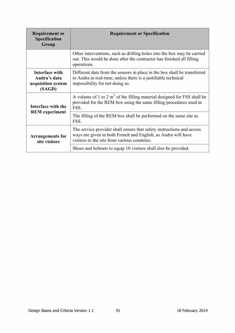
Design Bases and Criteria Version 1.1 91 18 February 2014
Requirement or
Specification
Group
Requirement or Specification
Other interventions, such as drilling holes into the box may be carried
out. This would be done after the contractor has finished all filling
operations.
Interface with
Andra’s data
acquisition system
(SAGD)
Different data from the sensors in place in the box shall be transferred
to Andra in real-time, unless there is a justifiable technical
impossibility for not doing so.
Interface with the
REM experiment
A volume of 1 to 2 m3 of the filling material designed for FSS shall be
provided for the REM box using the same filling procedures used in
FSS.
The filling of the REM box shall be performed on the same site as
FSS.
Arrangements for
site visitors
The service provider shall ensure that safety instructions and access
ways are given in both French and English, as Andra will have
visitors to the site from various countries.
Shoes and helmets to equip 10 visitors shall also be provided.

Design Bases and Criteria Version 1.1 92 18 February 2014
7. ELSA Design Basis
ELSA is a programme of laboratory and small scale in situ experiments that will be used to
further develop the reference shaft seal for the German reference disposal concepts for
repositories in salt and clay host rocks. This section describes the process by which the
design basis for the shaft seals and the ELSA experiment are developed in Germany, and
describes the design basis for both the reference shaft seal and for the ELSA experiments.
7.1 Process used to Develop the Design Basis
7.1.1 Definition of the Design Basis and Method used to Describe the Design Basis
In the German programme, the design basis consists of the boundary conditions and
requirements on a specific structure in the host rocks under consideration.
No formal requirements management system or systems approach has been adopted in the
national repository programme. Instead, general regulations, such as the Eurocode standard
for geotechnical design EC7 (DIN EN 1997-1), national regulations such as the BMU
repository safety requirements and mining law, and an iterative cycle of design and
performance assessment will be used to define requirements on monitoring and quality
management of the construction process, the material properties, and investigation of the
construction site.
In Germany, a concept for the demonstration of safety, the Safety Assessment Concept, has
been developed (Mönig et al., 2012). The safety concept relies on siting to ensure
confinement by the geological barrier, and demonstration of confinement of radionuclides by
the waste and the engineered barriers, in particular the drift and shaft seals. The safety
concept is captured within a hierarchical structure of protection goals, safety assessment
components and safety functions (Figure 7.1). This hierarchy allows a link to be established
between the safety functions of the repository components and the protection goals.
With regard to geotechnical barriers, a safety demonstration and verification concept has
recently been developed. This concept is described by Herold & Müller-Hoeppe (2013)
together with application examples especially for elements of a shaft sealing system.
7.1.2 Development of the Design Basis
The development of the design basis for shafts in the German project is based on experience
from the mining industry, previous shaft sealing experiments, the preliminary safety analysis
for Gorleben (VSG) (see Section 2.2.5), and research into shaft sealing elements.
Mining Industry
In Germany, there is comprehensive knowledge on the long-term performance of shaft seals
(referred to as shaft safekeeping), which is based on the experience gained from shaft sealing
in salt and potash mining in the past 90 years. The knowledge is used and developed further
in the development of repository shaft seal designs.
Shaft sealing experiment at Salzdetfurth
DBE TEC together with the Technical University of Freiberg participated in the four-year
large-scale shaft sealing experiment at Salzdetfurth, Germany between 1998 and 2002 (see
Appendix B). This experiment provided fundamental understanding of bentonite saturation
and swelling processes.

Design Bases and Criteria Version 1.1 93 18 February 2014
Figure 7.1: Hierarchy of protection goals, safety assessment components and safety
functions for the German Safety Assessment Concept.
VSG Safety Analysis
Within the scope of the VSG safety analysis, a shaft sealing system has been developed, the
concept of which is descried in Section 7.2. The VSG analysis built on a previous safety
assessment focused on demonstration of the integrity of engineered barriers (Krone et al.,
2008). Based on this concept, a preliminary shaft sealing system has been developed within
the scope of the VSG. This has been performed in four steps:
1. Clarify the site-specific boundary conditions for the sealing system. All stratigraphic
units were considered and evaluated with regard to placement of individual sealing
components. One characteristic of the host rock, for example, is the presence of
several discontinuities. It is planned to place sealing elements at all these locations.
2. Identify regulatory and other requirements that have to be met. In particular, new
safety criteria for disposal of radioactive waste as well as the recently developed
safety assessment concept (Mönig et al., 2012) were considered. In addition to this,
results of previous large-scale in situ experiments were compiled and evaluated and
useful information taken into account. Based on this evaluation, reference materials
were selected for the different sealing elements.

Design Bases and Criteria Version 1.1 94 18 February 2014
3. A preliminary design of the sealing system was developed taking into account
chemical, mechanical, and hydraulic impacts on all individual components to check
whether these impacts can be controlled.
4. Carry out performance assessment calculations based on expected component
properties in order to determine the effectiveness of the sealing system and to check
whether the system as a whole will fulfil its safety functions.
Research
The Technical University of Freiberg, a partner in the ELSA Project, completed a research
project in 2009 (Kudla et al 2009) to develop specific shaft sealing elements, select suitable
materials, and develop a practical solution for implementation. These materials form the
basis for the current shaft design.
Development of the Design Basis within ELSA
The ELSA Project is divided into three phases:
Phase 1: Boundary conditions and requirements for shaft seals in salt and clay host
rocks (Kudla et al., 2013), (Jobmann, 2013), and (Herold & Müller-Hoeppe, 2013).
Phase 2: Development of shaft seal concepts and testing of functional elements of
shaft seals in laboratory tests and in small-scale tests, including testing and calibration
of mathematical models of material behaviour.
Phase 3: A large-scale demonstration experiment of particular sealing components
and adjustment of the sealing concept. The main requirements of the experiment are
to demonstrate technical feasibility and long-term effectiveness. It has not yet been
determined which components will be tested within this phase of the ELSA project.
The following tests during Phase 2 of ELSA contribute to development of shaft sealing
concepts and designs to conduct the large-scale experiments in Phase 3:
Tests regarding the technical feasibility of filling columns made of compacted rock
salt (crushed salt or pre-compacted material).
Investigations regarding the suitability of calottes (concave sections) made of basalt as
an additional element in gravel columns to reduce settlement.
Abutments made of MgO concrete cast in situ.
Further development of treatment methods for the EDZ and the interfaces between
concrete and the surrounding rock mass based on grout injection.
Further development of the design and construction of asphalt seals and quality
assurance procedures for these seals.
Additional studies on bentonite seals in clay formations focusing on the placing of
several equipotential elements within the bentonite element. This is to avoid or to
significantly reduce an inhomogeneous saturation of the bentonite element. These
equipotential elements will consist of a material that allows a fast distribution of water
within it. Thus, each following section of bentonite will be wetted on its complete
surface area.
Generation of models to analyse the properties of the material as well as the loading
and flow processes at the various construction stages.
Design Bases and Criteria Version 1.1 95 18 February 2014
In addition to these investigations, the laboratory programme of GRS (Lava and Lasa
Projects) will address sealing materials planned to be utilised in the shaft seals as well. The
programme aims at providing experimental data needed for the theoretical analysis of the
long-term behaviour of MgO and cement based salt concrete in interaction with the host rock
and fluids. The data gained will be needed to show the long-term preservation of the required
hydraulic conductivity of the seals. The experiments comprise the following mechanical and
geochemical investigations:
Uniaxial multistep creep tests on samples of salt concrete and sorel concrete for the
determination of creep parameters.
Triaxial compression tests on samples of salt concrete and sorel concrete with axial
flow of salt solutions (NaCl and IP21) for determination of time-dependent
compaction and sealing effectiveness against brines.
Long-term re-compaction tests on pre-damaged samples of salt concrete and sorel
concrete under isostatic load with injection of salt solutions (evolution of brine
conductivity as the self-sealing indicator).
Experimental long-term simulations of the systems rock salt / salt concrete and rock
salt / sorel concrete using large hollow salt cylinders filled with concrete under
varying triaxial load and brine pressure.
Batch experiments with crushed concrete suited to determine the geochemical path of
the alteration until a final equilibrium between material and brine is reached.
In-diffusion experiments with the concrete and the brine in order to determine the
velocity of the alteration in the porous matrix.
Experiments with the concrete and brine at the contact with the EDZ in order to
determine the velocity of the alteration of the sealing material due to advective flow at
the boundary with the rock formation.
7.2 Design Basis for the Reference Shaft Seal
In order to meet the requirements laid down in the repository regulations and mining law, the
primary safety function for shaft and drift seals has been specified as being to provide a
sufficiently low hydraulic conductivity to avoid brine paths into the repository and the
movement of radionuclides out of it.
The national repository safety requirements promulgated by BMU contain general
requirements for planning and constructing a HLW repository (BMU, 2010). These
requirements also influence the design and construction of shaft seals. Requirements related
to the design of plugs and seals are given in sections 4 and 7 of the BMU safety requirements.
Plugs and seals must avoid significant radiological release. The hydraulic conductivity of the
sealing elements must be sufficiently low. They have to be designed with no need for
maintenance or corrections after construction. Plugs and seals have to be constructed in a
quality-assured manner and taking into account all requirements set to the barriers. The long-
time safety of the barriers has to be verified, and the feasibility of their technical realisation
must be shown. The integrity of the barrier must be shown for the important loads.
The safety requirements of BMU refer also to the mining law. The requirements from
common mining have to be considered, e.g. the "Guideline for the safekeeping of shafts".
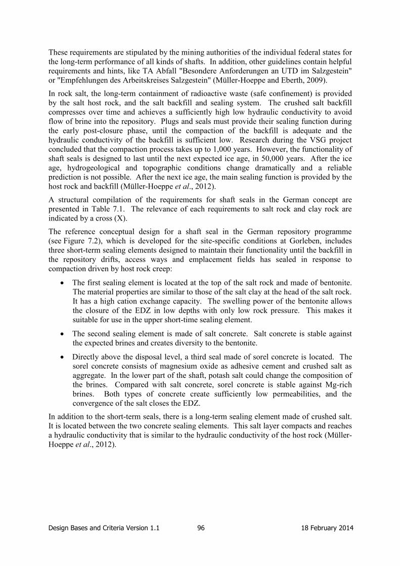
Design Bases and Criteria Version 1.1 96 18 February 2014
These requirements are stipulated by the mining authorities of the individual federal states for
the long-term performance of all kinds of shafts. In addition, other guidelines contain helpful
requirements and hints, like TA Abfall "Besondere Anforderungen an UTD im Salzgestein"
or "Empfehlungen des Arbeitskreises Salzgestein" (Müller-Hoeppe and Eberth, 2009).
In rock salt, the long-term containment of radioactive waste (safe confinement) is provided
by the salt host rock, and the salt backfill and sealing system. The crushed salt backfill
compresses over time and achieves a sufficiently high low hydraulic conductivity to avoid
flow of brine into the repository. Plugs and seals must provide their sealing function during
the early post-closure phase, until the compaction of the backfill is adequate and the
hydraulic conductivity of the backfill is sufficient low. Research during the VSG project
concluded that the compaction process takes up to 1,000 years. However, the functionality of
shaft seals is designed to last until the next expected ice age, in 50,000 years. After the ice
age, hydrogeological and topographic conditions change dramatically and a reliable
prediction is not possible. After the next ice age, the main sealing function is provided by the
host rock and backfill (Müller-Hoeppe et al., 2012).
A structural compilation of the requirements for shaft seals in the German concept are
presented in Table 7.1. The relevance of each requirements to salt rock and clay rock are
indicated by a cross (X).
The reference conceptual design for a shaft seal in the German repository programme
(see Figure 7.2), which is developed for the site-specific conditions at Gorleben, includes
three short-term sealing elements designed to maintain their functionality until the backfill in
the repository drifts, access ways and emplacement fields has sealed in response to
compaction driven by host rock creep:
The first sealing element is located at the top of the salt rock and made of bentonite.
The material properties are similar to those of the salt clay at the head of the salt rock.
It has a high cation exchange capacity. The swelling power of the bentonite allows
the closure of the EDZ in low depths with only low rock pressure. This makes it
suitable for use in the upper short-time sealing element.
The second sealing element is made of salt concrete. Salt concrete is stable against
the expected brines and creates diversity to the bentonite.
Directly above the disposal level, a third seal made of sorel concrete is located. The
sorel concrete consists of magnesium oxide as adhesive cement and crushed salt as
aggregate. In the lower part of the shaft, potash salt could change the composition of
the brines. Compared with salt concrete, sorel concrete is stable against Mg-rich
brines. Both types of concrete create sufficiently low permeabilities, and the
convergence of the salt closes the EDZ.
In addition to the short-term seals, there is a long-term sealing element made of crushed salt.
It is located between the two concrete sealing elements. This salt layer compacts and reaches
a hydraulic conductivity that is similar to the hydraulic conductivity of the host rock (Müller-
Hoeppe et al., 2012).

Design Bases and Criteria Version 1.1 97 18 February 2014
Figure 7.2: Reference conceptual design for the German shaft seal. The elements
considered in the safety assessment are framed in red (Müller-Hoeppe et al.,
2012). The Gorlebenbank is a folded anhydrite layer in the rock salt.
7.3 ELSA Design Basis and Link to Design Basis of Reference Design
The aim of the ELSA project is to develop generic design concepts for shaft seals in salt and
clay host rocks that comply with the requirements for a repository for HLW (Jobmann, 2013)
and to carry out the necessary preparatory work. The design basis for the ELSA experiment
is based on the shaft seal design basis described in Section 7.2. The experiment design will
have to be adapted to the geological and geometrical conditions to be found at the actual
testing site which has not yet been decided. Currently, it is not intended to seal a complete
shaft but to only test prototypes of the different sealing elements on a large scale.

Design Bases and Criteria Version 1.1 98 18 February 2014
Table 7.1: Requirements on plugs and seals in the German concept (Kudla et al., 2013)
and (Jobmann, 2013).
Source Requirement Rock
salt
Claystone
Safety
requirements
of BMU
Process analysis of impacts on shaft seal
If components of the shaft seal are located in the
isolating rock mass, the velocities of the
transport processes in the components habe to
be comparable with those of diffusive transport
processes (sufficiently low permeability)
Swelling pressures in the sealing elements are
not to exceed the rock strength
If there are no technical regulations for
geotechnical barriers, their construction,
erection and function generally have to be
verified through practical tests. (May not be
necessary, if robustness can be verified by other
means or if sufficient safety margins exist.)
To verify the integrity of the structure, the
relevant load cases and construction material
properties are to be analyzed. Sufficient load
bearing capacity and resistance to ageing of the
construction material is to be verified for the
same period that the structures need to be fully
functional.
As far as necessary, immediately effective
barriers have to isolate the waste for the period
where barriers that are effective in the long term
have not yet become completely effective.
Possible requirements resulting from an analysis
of release scenarios have to be identified and
taken into account.
If possible, redundancy and diversity are to be
integrated in the shaft seal, e.g. by using several
sealing elements made of different materials.
The shaft seal in combination with the other
barriers (e.g. drift seals) is to be assessed with
regard to its importance for the safety of the
repository e.g.to determine the required period
of effectiveness).
X
X
X
X
X
X
X
X
X
X
X
X
X
X
X
X
X
X

Design Bases and Criteria Version 1.1 99 18 February 2014
Source Requirement Rock
salt
Claystone
Safety and
verification
concepts
Maximum period of effectiveness: 50,000 years
(next glacial period). Limitations regarding
sealing concept (rock salt):
The shaft seal has to be sufficiently tight until the
hydraulic resistance of the compacting crushed salt
backfill is sufficiently high. (according to current
estimates, approx. 1,000 years) Consequently, the
volumetric flow has to be so low that inflowing
brines do not reach the crushed salt backfill in the
access drifts until after 1000 years (hydraulic
requirement).
Maximum period of effectiveness: 50,000 years
(next glacial period). Limitations regarding
sealing concept (claystone):
still pending
Draft design of the shaft seal (dimensioning, -
properties and demonstration of generell
feasibility)
Consequence analysis taking into account a FEP
list with probable and less probable processes.
Resulting requirements on functional elements
are to be taken into account (if necessary,
iterative optimization).
Prevention of advective fluid flow out of the
repository and out of the isolating rock mass.
Maintaining a stable geochemical environment
Use of material with high sorption capacity
X
–
X
X
–
–
–
-
X
X
X
X
X
X
Technical
functional
verification
The design of the sealing system should be
based on the technical standards and regulations
DIN EN 1997-1 Eurocode 7, DIN EN 1990
Eurocode, DGGT-GDA recommendations and
DAfStb guideline 2004.
The individual functional elements of a shaft
seal are to be designed in such a way that a
functional verification pursuant to the
demonstration concept can be carried out.
To demonstrate sufficient hydraulic tightness,
X
X
X
X

Design Bases and Criteria Version 1.1 100 18 February 2014
Source Requirement Rock
salt
Claystone
the individual elements on their own and in
combination with the contact zone and the
excavation damaged zone are to be considered
(integral tightness).
In sections where sealing elements are to be
located, the excavation damaged zone is to be
removed to an appropriate depth.
If the sealing concept stipulates that a sealing
element is to be effective immediately, the
sealing element has to be either constructed of
material capable of swelling or a material has to
be used that - due to other properties - is in
direct contact with the rock and is able to
maintain this contact even under fluid pressure
(e.g. bitumen or asphalt) so that the contact zone
is sealed. In addition to this, the “loosened”
zone that forms after the EDZ has been trimmed
may have to be improved by means of technical
injection measures.
If non-cohesive, non-self-supporting sealing
material is used, a supporting column with
limited settlement capacity (settlement max.
3 % of the seal’s length) is to be installed.
To avoid erosion and suffusion, it is imperative
to use filter layers in the sealing element.
A complete and consistent data set needs to be
available for all materials characterising the
material’s behavior and properties.
X
X
X
X
X
X
X
X
X
X
X
X
Site-specific
boundary
conditions
If the shaft to be sealed penetrates fault zones or
zones that may bear fluids, the fluid-bearing
zones need to be sealed by means of sealing
elements that have sufficient overlap.
Depending on the pore solutions, the materials
for the sealing elements are to be selected such
that no significant corrosion occurs if such
solutions appear.
Sealing elements that are not capable of
swelling are to be positioned at the lowest
X
X
X
X
X
X

Design Bases and Criteria Version 1.1 101 18 February 2014
Source Requirement Rock
salt
Claystone
possible point in the shaft.
The emplacement level is to be isolated from
other levels (e.g. exploration level) by means of
a sealing element.
Where clayey and sandy facies alternate, sealing
elements are to be located in the clayey facies to
prevent fluid migration through the sandy facies
around the barrier.
If several aquifers are present, an
interconnection is to be prevented by means of
sealing.
The components of the shaft seal are to be
designed to withstand the maximum possible
vertical fluid pressure at the site plus an
additional 50 m (fixed) due to climate-induced
sea-level changes.
X
–
X
X
X
X
X
X
Other
requirements
After decommissioning, shafts are to be
completely backfilled.
Prior to backfilling, shaft furnitures should be
completely removed if this does not pose any
occupational safety risk.
Existing water-tight linings in areas where
aquifers are present shall not be removed.
Liners in horizons where seals are to be placed
are removed to avoid leakages and infiltrations.
In horizons where seals are to be placed, the
excavation damaged zone in the shaft wall shall
be removed to an appropriate depth.
The entrances to the drifts are secured against
movement of the filling column.
Sealing elements in the shaft made of materials
that are not capable of swelling (e.g. salt or
sorel concrete), need to be in direct and firm
contact with the rock mass.
The backfill columns are installed in a dry
environment.
X
X
X
X
X
X
X
X
X
X
X
X
X
X
X
X

Design Bases and Criteria Version 1.1 102 18 February 2014
8. Discussion
In this section, the development, content and presentation of the design basis for plugs and
seals is discussed. The aim is to address the commonalities and differences in the design
bases for plugs and seals for different host rocks, disposal concepts and national programmes.
The discussion is separated into two sections: the process used to develop, maintain and
present the design basis (Section 8.1) and the content of the design basis (Section 8.2),
although in practice it is not possible to entirely separate discussion of process and content.
8.1 Design Basis Development Process
8.1.1 Definition of the Design Basis
All WMO partners in DOPAS, including those not directly implementing a full-scale
experiment (Nagra, NDA RWMD and NRG), manage the development of designs through a
process that includes identification of the requirements on structures and the conditions under
which these requirements must be met. Requirements most commonly relate to the
performance needed from the structure (e.g. the ability to withstand loads). Conditions relate
to the environment in which the structure is constructed (e.g. the dimensions, the
environmental conditions such as temperature and humidity, and the working conditions such
as man access and rate of emplacement). For all of these programmes, the design basis is
represented by a list of requirements on the structure (i.e. the plug or seal) and the conditions
under which these requirements must be met. Therefore, the understanding of what
constitutes a design basis is consistent across all WMOs in DOPAS.
In DOPAS, a distinction is made between the design basis for the reference repository
conceptual design and the design basis for the experiment. The reference design is the one
that is used across the national programme (e.g. for licensing). The design basis for the
experiment may differ from the design basis for the reference design because the experiments
may be testing only specific aspects of a plug or seal, because the testing may involve
acceleration of processes, or because the experiment may be testing a different design to the
reference. An example of an experiment considering only specific aspects of a seal is FSS,
which will not be saturated or otherwise pressurised. However, the design basis for FSS does
include requirements to ensure that the experiment is appropriately defined (e.g. the density
of the emplaced bentonite must be sufficient that it would provide the necessary swelling
pressure and hydraulic conductivity should the system be saturated). An example of the
acceleration of processes is the rate at which DOMPLU and EPSP will be pressurised, a
feature of the experiments that could have significant impacts on the performance of the
structures being tested. POPLU and EPSP are examples of experiments that are not
addressing the reference design.
In addition, the design basis for specific experiments is developed to a more detailed degree
than the design basis for the plugs and seals in the reference repository conceptual designs.
This is because the design bases for repository plugs and seals contain high-level
requirements and conditions that are fixed (see Section 8.1.2) and because outstanding
uncertainty does not allow more detailed specification of the reference designs at the present
time. In contrast, the design basis for the experiments must be specified in greater detail to
allow the experiment to be designed and implemented.
Although the understanding of the design basis consistently concerns both the requirements
and conditions on a structure, the development of the design bases for reference designs has
illustrated that these most frequently focus on identification of the requirements rather than

Design Bases and Criteria Version 1.1 103 18 February 2014
the conditions. This is partly owing to the maturity of the design basis definition. To date,
repository designs, including those that represent the basis for a licence application, are
flexible in order to manage uncertainty in underground conditions and the requirements of the
safety case.
In contrast, the work on development of the design bases for the DOPAS experiments and
tests indicates that the conditions as well as the performance requirements are included as
part of the design basis. For example, the design basis for FSS includes detailed dimensions
of the test box and breakouts, and the requirement for underground conditions to be
replicated during the experiment (relative humidity, temperature and timescale for transfer of
cement from the location of production to the emplacement location).
8.1.2 Iterative Development of the Design Basis
All of the design bases considered in DOPAS include national regulations and other
stakeholder requirements as a starting point. Examples include the further development of
particular technologies and materials in the case of EPSP (e.g. use of Czech bentonite and use
of fibre reinforced sprayed concrete) and the consideration of national repository safety
requirements and mining law in the case of ELSA.
High-level conceptual designs of plugs and seals typically build on existing designs for plugs
and seals applied in other industries. Examples include experience from the sealing of
hydroelectric plants in Sweden, development of plugs from gas storage facilities in the Czech
Republic, and experience of the sealing of salt and potash mine shafts in Germany
(see Appendix B). Therefore, technology transfer and existing knowledge is a significant
part of the process used to develop the design basis for plugs and seals in repository concepts.
High-level conceptual designs will allow the principal functions of plugs and seals to be
specified (e.g. for the KBS-3V deposition tunnel plug, the functions are to confine the
backfill in the tunnel, to support saturation of the backfill, and to provide a barrier to water
flow that may cause harmful erosion of the bentonite in buffer and backfill). These functions
will, at an appropriate stage in the programme, become fixed, although this should not occur
until significant confidence in the function (and the wording that is used to define it) has been
achieved.
Existing knowledge on plugs and seals can be used to propose more detailed functional
requirements that a plug or seal must achieve (e.g. a water leakage rate). These initial
requirements may be tested through full-scale demonstration and through performance
assessment studies, the learning from which is fed back into the design basis. Examples of
full-scale experiments that have been important in the development of the design bases for
the DOPAS experiments include the Stripa Tunnel Plugging Experiment, the Äspö Backfill
and Plug Test, the Äspö Prototype Repository, the TSX, the concrete plugs developed for the
Háje underground gas storage facility, and the Salzdetfurth Experimental Shaft.
Experimental tests and feasibility studies are carried out, the outcomes of which may result in
new updates to the detailed design requirements. For example, it may be found that using a
certain recipe of concrete for constructing a plug proved difficult or inadequate, and a change
may be required. Such testing can help to develop the design basis for plugs and seals, for
example the structures that they contain (concrete plugs, bentonite seals, filters etc.), the
acceptable materials (e.g. type of concrete) and the performance requirements (e.g. leakage
rates, swelling pressures and hydraulic conductivities). As performance assessments are
undertaken, more light can be shed on the expected long-term performance of the engineered
barriers. Any unacceptable results from a safety point of view can be analysed and the

Design Bases and Criteria Version 1.1 104 18 February 2014
relevant inputs, as dictated by the design basis requirements, may need to be re-evaluated.
This in turn can result in a need to modify a requirement or revise the already-established
safety functions.
In developing a design basis, it is therefore essential to use experience from any full-scale
experiments and ensure that collaboration and coordination of effort between designers,
safety evaluators and other experts are established. Therefore, the development of a design
basis can be considered as a continuous process where learning from new and previous
experiments, performance assessments, and changes in the safety concept can result in the
need to change some aspects of the design (e.g. Figure 8.1).
Figure 8.1: Iterative process for developing a design basis.

Design Bases and Criteria Version 1.1 105 18 February 2014
8.1.3 Management of Design Basis Requirements
Of the five WMOs developing an experiment in DOPAS, only two, SKB and Posiva, are
implementing a systems engineering approach to identification and management of the
design basis. SKB and Posiva have worked collaboratively on the implementation of RMSs
in their programmes and have introduced a hierarchical structure, consisting of five levels of
requirements (these five levels consist of stakeholder requirements, system requirements,
sub-system requirements, design requirements and design specifications). An RMS enables
information on the links between requirements, historical development of a requirement, and
reasons for adding or removing any entries to be recorded.
However, the systems developed by both SKB and Posiva have only partially been
introduced: the SKB system does not yet incorporate all of the requirements identified in the
Production Reports and the Posiva system concentrates on requirements related to post-
closure safety.
An issue for requirements management is the significant time and effort required to develop
and manage requirements. Andra, for example, where requirements are linked to the
phenomenological analysis of safety functions, required several years to develop an agreed
and stable set of safety functions for the repository concept and its constituent components.
These safety functions are fixed and have not changed since the publication of Dossier 2005,
although sub-functions (e.g. those related to gas migration) might be changed in the future.
In addition, two of the WMOs (SÚRAO and NDA RWMD) with less mature programmes
recognise the benefit of introducing RMSs during the early development of their repository
concepts. To date, SÚRAO has identified high-level requirements only, as the Czech
programme is focusing on conceptual studies. NDA RWMD has decided to implement an
RMS, and is currently developing the approach to its implementation. Requirements are
currently listed in the DSS documents, and the RMS is intended to help to ensure that the
DSS provides a unified and comprehensive specification of requirements. Work is currently
ongoing to develop the DSS requirements into a hierarchical structure. The hierarchical
structure will present systematically the DSS requirements from the highest level
requirements distilled from national policy, legislation, regulatory requirements, and
boundary conditions set out by NDA RWMD, down to disposal system generic safety
functional requirements in terms of design, construction, operation and closure of the disposal
system.
All of the WMOs in DOPAS are currently managing the design basis for plugs and seals (and
the design basis for the repository) through documentation. These documents contain lists of
requirements and conditions on the structures, and different methods for describing the
background, interpretation and justification of the requirements. This is an area of
management that can be improved and the DOPAS Project has helped in doing so.
8.2 Content of the Design Basis
8.2.1 Influence of Host Rock on Plugs and Seals Design Basis
The repository host rock can have a significant influence on the design basis for plugs and
seals.
Typically, crystalline rocks are relatively strong but potentially contain water-conducting
features (e.g. fractures) either naturally or as part of an EDZ resulting from construction.
Therefore, the design basis for crystalline rocks may include specific requirements associated
with both the presence of these features and the impact on the EDZ of construction methods.

Design Bases and Criteria Version 1.1 106 18 February 2014
For example, the DOMPLU design basis includes a requirement that the excavation method
shall minimise the development of an EDZ, and a requirement that rock surfaces connecting
to the concrete dome abutment shall be free from an EDZ with harmful impact. Further
discussion of requirements on EDZ for plugs and seals is provided below (Section 8.2.3).
However, the main impact of crystalline host rocks on plugs and seals is associated with the
disposal concept developed for such rocks. The KBS-3 method, in particular, places a high
reliance on containment by the canister and key functions of the buffer and the deposition
tunnel backfill are to protect the canister. Therefore, the deposition tunnel plug does not have
a post-closure safety role and its main function is to protect the bentonite in the deposition
hole buffer and in the deposition tunnel backfill from erosion, and the buffer and backfill
from piping.
In contrast with typical crystalline rocks, clay and salt host rocks are relatively weak and are
expected to have very low hydraulic conductivity. The repository access ways represent a
possible short circuit to the geosphere containment function. Therefore, the key function for
seals in these systems is to seal the repository such that groundwater flow into and out of the
repository is restricted. This function is expected to last until the host rock and backfill have
re-established in situ hydraulic performance, which may be a period of hundreds of years in a
salt and thousands of years in clay (see Sections 6 and 7).
8.2.2 Differences between the Presentation by SKB and Posiva of the Reference Repository
Design Basis and the DOMPLU and POPLU Design Basis
SKB and Posiva have both submitted a licence application based on the KBS-3V method, and
DOMPLU and POPLU are both experiments of deposition tunnel plugs. However, there are
differences between the design basis for the reference deposition tunnel plugs and the
DOPAS experiments.
With respect to the reference deposition tunnel plugs, the principal difference is the manner
of presentation of the design basis. SKB has divided the design basis into three timeframes
related to the production phase (which includes construction and curing of the concrete
dome), the sealing phase and the post-closure phase. Posiva, for whom the RMS
concentrates on post-closure requirements do not divide their requirements in the same
manner. The difference in presentation of the two design bases makes a comparison of their
details difficult, as it is not necessarily straightforward to identify the corresponding
requirements from each set.
However, this is only a presentational issue, and the requirements on the reference designs
are essentially the same. These include the identification of the main components of
deposition tunnel plugs (concrete dome, bentonite seal and filter layer), the operational
lifetime (100 years), and the requirement for low hydraulic conductivity, low pH and low
organic content in the plug materials. There are differences in the presentation of these last
three requirements. A hydraulic conductivity limit of 1 x 10-11
m/s is specified in the case of
Posiva, whereas SKB expresses the hydraulic conductivity in terms of its function to limit the
erosion of bentonite from the seal. SKB defines a pH value of ≤ 11, whereas Posiva
expresses the requirement for low pH in terms of a calcium to silica mass ratio because this
obviates the need to define the timeframe when the pH value must be met.
DOMPLU and POPLU are experiments of different types of deposition tunnel plug.
Therefore, although the high-level requirements are the same (isolate the deposition tunnels
hydraulically, the chemical composition of the plugs shall not jeopardise the performance of
the backfill, buffer and canister, and the plugs shall keep the backfill in place during the
operational phase), the more detailed design basis is different.

Design Bases and Criteria Version 1.1 107 18 February 2014
The differences are mainly driven by Posiva’s desire to test an alternative to the reference
deposition tunnel plug design. Posiva is testing an alternative to the reference design to:
Evaluate whether the previous Posiva reference design was still valid.
Evaluate if an alternative design could be added to the reference design to provide
flexibility during implementation.
Evaluate if a simpler design could be introduced.
Other significant differences between the DOMPLU and POPLU design bases are as follows:
The SKB design basis includes additional requirements on the construction of the
deposition tunnel plug that are not in the Posiva design basis. These include a
requirement for high reliability, a requirement on the rate of construction, use of well-
tried or tested techniques, and cost-effectiveness. Such requirements are not included
in the Posiva design basis, mainly because Posiva has decided to focus on long-term
requirements, but also because the Posiva programme does not have the same
restrictions on the rate of disposal as SKB and, therefore, Posiva has not considered it
necessary to develop such requirements at this stage in the process.
There is less water inflow into tunnels in Olkiluoto compared to Äspö, and, therefore,
there may not be a requirement for POPLU to contain a filter.
For POPLU, it has been proposed to use steel reinforcement, which means that there
is no need for cooling pipes to manage the shrinkage of the concrete structure during
curing.
POPLU will be implemented in ONKALO, which has stricter requirements on the use
of materials than Äspö, owing to its future development as part of the repository. In
particular, this means that superplasticisers that incorporate polycarboxylates cannot
be used. An example is Glenium 51, a superplasticiser that is not allowed in
ONKALO, but is used at Äspö.
Nonetheless, in order for the results of the experiments to be compared, the design basis for
performance monitoring of POPLU is as close as possible to the performance monitoring
plans of DOMPLU and the pressurisation steps will also be similar.
8.2.3 Current Practice in Defining the Design Basis for Plugs and Seals
The design bases have illustrated different approaches to specification of the design basis for
similar features and processes of plugs and seals. These are discussed below in relation to
hydraulic, mechanical, chemical and gas issues. In addition, the current approaches to
defining other aspects of the design basis, including the incorporation of operational issues,
are discussed.
Requirements on Hydraulic Performance
The hydraulic function of plugs and seals responds to different safety functions in different
disposal concepts. For the Cigéo repository concept, the hydraulic conductivity of the seal
must be equal to or less than 1 x 10⁻⁹
m/s, to meet the performance assessment requirement
that groundwater flow is predominantly through the geosphere. For the crystalline rock
cases, especially DOMPLU and POPLU, the requirement is that the water flow does not lead
to piping and erosion of the deposition tunnel backfill.
Definition of the hydraulic function is undertaken following an analysis of the main pathways
through the plug or seal. For DOMPLU, the main pathways are likely to be the contact

Design Bases and Criteria Version 1.1 108 18 February 2014
between the concrete dome and the rock and through the EDZ. In terms of the contact zone,
the design basis is based on a regular discontinuity being developed between the concrete and
the rock, which relies on a smooth rock surface (which is produced by wire sawing) and
homogeneous cooling of the concrete (which leads to the introduction of cooling pipes). The
shrinkage gap that is formed during cooling is grouted, and, owing to the small volume of
grout required, it is considered acceptable to use high-pH grout. In terms of the EDZ, this
requires appropriate construction techniques to be employed and appropriate siting of the
plug. Existing requirements on the EDZ call for the region to be free from through-going
discontinuities, but this requirement is not verifiable by existing methods (e.g. imaging using
ground penetrating radar). However, further work is required to understand how a verifiable
requirement on the hydraulic conductivity of the EDZ can be set – such a requirement would
need to be site-specific and could make use of 3D techniques for stochastic modelling of
fracture systems.
A further issue is the measurement of any leakage across the plug. DOMPLU is currently
investigating the water leakage value that can be achieved for a plug. In ventilated tunnels,
water leaking through a plug at the expected low rate would evaporate rather than condense,
and is therefore difficult to measure. SKB is using a plastic sheet over the DOMPLU
experiment to reduce the effects of ventilation on any water that leaks through the seal.
For FSS and EPSP, the bentonite in the system provides a significant hydraulic function.
However, the design basis for both experiments recognises that definition of the hydraulic
conductivity of the bentonite depends on the density that can be achieved during
emplacement. For EPSP the decision has been made to define the density of the bentonite;
this is regarded as a practical approach to definition of the design basis. For FSS, the design
basis has been defined in terms of the required hydraulic conductivity, as this has been
defined in response to performance assessment studies, although the bentonite dry density
will be monitored to establish whether the required hydraulic conductivity is achieved.
Requirements on Mechanical Performance
In terms of mechanical performance, a key issue to be considered in the development of a
design basis is whether or not a filter or transition zone is required to reduce pressures acting
on the principal component of the plug. This must be decided during the development of the
design basis in order to place the appropriate requirements on the filter if it is included. The
inclusion of a filter would reduce the required performance of the principal component of a
plug (e.g. a concrete dome) during construction, but would make installation of the plug more
complicated. It is anticipated that the work on POPLU, which is currently on-going, will
contribute to consideration of the need for transition zones in plugs.
Requirements on Chemical Performance
In terms of chemical performance, the issues include the potential for interaction of any
cementitious materials with clay materials, in particular the potential for high-pH waters
emanating from cement reducing the performance of bentonite seals and/or clay host rocks,
and the possible impact of any harmful substances. This has been addressed in all designs by
requiring low-pH cement to be used for all cementitious materials, with the exception of the
contact grout to be used in DOMPLU.
However, the approach to specifying the chemical performance of cementitious materials for
each of the full-scale experiments in DOPAS is different:
For DOMPLU, a pH value of ≤11 is specified as a requirement.

Design Bases and Criteria Version 1.1 109 18 February 2014
For POPLU, a calcium to silica mass ratio less than 1:6 is specified (the value of this
ratio is currently under review).
For EPSP, which concentrates on fundamental understanding of materials, a less
stringent requirement is set which requires that cement with a relatively low pH shall
be used for all the concrete and shotcrete components to develop further
understanding of these materials.
For FSS, an original specification that required the concrete plugs to have a pH of
10.5 to 11 by 28 days after mixing was found to be quite optimistic during initial
testing. This requirement has been modified so that the pH value has to be fulfilled
by 90 days after mixing.
Requirements on the introduction of harmful substances are recognised in the POPLU design
basis; plug materials shall be selected so as to limit the contents of harmful substances
(organics, oxidising compounds, sulphur, and nitrogen compounds) and microbial activity.
This does not feature in other experiment design bases, as the experiments are not at potential
repository sites.
Requirements on Gas Migration
Of the DOPAS experiments, the only requirements related to gas, are for the gas permeability
of the FSS concrete to be measured. There are no particular requirements that set for gas
migration for DOMPLU, POPLU, ELSA and EPSP.
Requirements on the Host Rock
The current assumption for all programmes is that plugs and seals will be of a single design
and rock requirements will be defined in concert with plug and seal requirements. An
alternative approach would be for WMOs to adopt flexible design bases for plugs and seals,
for example developing more than one plug design, which could provide greater flexibility in
responding to rock conditions encountered during operations. This would mitigate against
the loss of deposition tunnels on grounds of unsuitability should rock conditions not meet the
most stringent requirements.
Requirements on Operational Issues
DOMPLU and FSS also recognise requirements related to operational issues. As
implementation of geological disposal moves closer, operational considerations may become
a more significant aspect of the design basis, especially for KBS-3V, where construction of
deposition tunnel plugs may need to take account of other underground activities.
Operational requirements for other experiments in DOPAS have not been documented yet.

Design Bases and Criteria Version 1.1 110 18 February 2014
9. Conclusions
This report has compiled the design basis for the five full-scale experiments, laboratory tests,
and performance assessment studies of plugs and seals for geological repositories in DOPAS.
This includes the design bases for:
SKB’s reference conceptual design for deposition tunnel plugs and for DOMPLU.
Posiva’s reference conceptual design for deposition tunnel plugs and for POPLU.
SÚRAO’s design basis for EPSP.
Andra’s reference conceptual design for drift and ILW disposal vault seals and for
FSS.
The German reference design for shaft seals.
In addition, information has been collated on the design bases for plugs and seals in the other
national programmes represented in DOPAS (Switzerland, the Netherlands and the UK).
Work on the design basis in DOPAS has allowed assessment of current practice with regard
to both the process used to develop and describe the design basis and the content of the
design basis. As such, there are general conclusions to be drawn that are relevant to the
design basis for other aspects of repository design as well as lessons specific to plugs and
seals. A distinction is made between the design basis for the reference repository conceptual
design and the design basis for the experiment, as the full-scale experiments, laboratory tests,
and performance assessment studies are each only investigating specific aspects of the
reference designs.
Design Basis Process
For all of these programmes, the design basis is represented by a list of requirements on the
structure (i.e. the plug or seal) and the conditions under which these requirements must be
met (the dimensions, the environmental conditions and the evolution of the system). They
may also include procedural requirements.
Design bases are hierarchical and consist of high-level requirements and low-level
requirements. National programmes organise this hierarchy in different ways.
The high-level design basis can be specified and stabilised once the repository concept has
been specified and the national regulations developed. This remains fixed. The high-level
design basis will describe the principal safety functions of a plug or seal, typically in a
qualitative fashion.
The lower level, more specific design basis is developed through an iterative process. The
design basis for all of the experiments being conducted in DOPAS specifies the components
of the plugs and seals, their dimensions and their expected performance.
The design basis is developed in an iterative fashion with inputs from regulations, technology
transfer, tests and full-scale demonstrations, and performance and safety assessments.
Existing design bases are all presented in documents (reports) as lists of requirements,
typically structured or grouped under a range of subjects, some of which relate to the specific
components in a plug or seal. Management of requirements can be aided by the use of an
electronic RMS, which provides benefits in terms of linking requirements and organising
them into a structured hierarchy. However, no organisation has yet fully implemented the
design basis for a plug or seal in an RMS.

Design Bases and Criteria Version 1.1 111 18 February 2014
Design Basis Content
The host rock and disposal concept have a significant impact on the design basis for plugs
and seals. Deposition tunnel plugs being developed for KBS-3V are focused on keeping the
backfill in place. Seals developed for clay and salt host rocks can make use of the creep
properties of these rocks.
Although SKB and Posiva have the same reference design for deposition tunnel plugs,
DOMPLU and POPLU are testing different designs. This is primarily driven by a desire to
assess a different type of plug to the reference design, especially one that might be
constructed using simpler methods. Specific differences between DOMPLU and POPLU are
driven by differences in the design of the respective repositories, the nature of the host rock,
and because DOMPLU is being developed in a generic URL, whereas POPLU is developed
at the site of a future planned repository.
Collation of the design basis of the reference conceptual designs and DOPAS experiments
has highlighted key differences and issues for further consideration with respect to the
definition of the design basis:
Cementitious materials should have low pH; this is defined by a pH target in some
programmes and a calcium to silica ratio in others.
Work is on-going on the density to which bentonite can be emplaced for the different
plugs and seals being considered in DOPAS. For some plugs and seals, bentonite
requirements are expressed in terms of the swelling pressure and hydraulic
conductivity to be achieved; in others it is expressed as the density of the bentonite.
The work on the design basis has illustrated that operational issues are important
considerations to be included in the design basis.

Design Bases and Criteria Version 1.1 112 18 February 2014
10. References
Alonso, J., Garcia-Siñeriz, J.L., Bárcena, I., Alonso, M.C., Luco, L.F., Garciá, J.L., Fries, T.,
Petterson, S., Bodén, A., Salo, J-P. (2008). ESDRED Module 4 (Temporary Sealing
Technology) Final Technical Report.
Andra (2005). Dossier 2005 Argile: Safety evaluation of a geological repository.
Andra (2012). Cahier des charges FSS-1: Etude et réalisation – Démonstrateur technologique
de scellement à pleine échelle (Full Scale Sealing).
CG.TE.F.CDC.AMOA.GC0.2000.12.0014.
Andra (2013). The Cigéo Project. Meuse/Haute-Marne Reversible Geological Disposal
Facility for Radioactive Waste. Project Owner File Public Debate of 15 May to 15 October
2013.
Anttila, P., Arenius, M., Haapala, K., Hansen, J., Hellä, P., Jalonen, T., Lahdenperä, J.,
Lyytinen, T., Mellanen, S., Vuorio, P., & Äikäs, T. (2009). Testing and demonstrations in
ONKALO – Aims and Needs. Eurajoki, Finland: Posiva Oy. Working report 2009-24.
ASN (2008). Guide de sûreté relatif au stockage définitif des déchets radioactifs en
formation géologique profonde. Version of 12/02/2008.
Auld, F.A. (1996). Design of Underground Plugs, Chapter 10 in Sealing of Boreholes and
Underground Excavations in Rock, pp 225-266, edited by Fuenkajorn, J. and Daemen, J.J.K.,
Chapman and Hall, London, 1996.
BMU (2010). Federal Ministry for the Environment, Nature Conservation and Nuclear
Safety: Safety Requirements Governing the Final Disposal of Heat-Generating Radioactive
Waste. Version of Sept., 30. 2010.
Dixon, D., Börgesson, L., Gunnarson, D., and Hansen, J. (2009). Plugs for Deposition
Tunnels in a Deep Geologic Repository in Granitic Rock – Concepts and Experience. SKB
Report R-09-50.
Gray, M. (1993). OECD-NEA International Stripa Project, 1980-1992, Overview.
Volume III, Engineered Barriers.
Gunnarsson, D., Börgesson, L., Hökmark, H., Johannesson, L-E., and Torbjörn, S. (2001).
Äspö Hard Rock Laboratory, Report on the Installation of the Backfill and Plug Test. SKB
International Progress Report IPR-01-17, May 2001.
Haaramo, M. (1999). Sijoitustunneleiden Sulkurakenteiden Rakennesuunnittelu. Working
Report 99-71. Posiva Oy. (In Finnish).
Haaramo, M. and Lehtonen, A. (2009). Principle Plug Design for Deposition Tunnels.
Working Report 2009-38.
Herold, P. and Müller-Hoeppe, N. (2013). Safety Demonstration and Verification Concept –
Principle and Application Examples. Technical Report (Extraction from Kudla et al., 2013),
DBE TECHNOLOGY, Peine.

Design Bases and Criteria Version 1.1 113 18 February 2014
Hilar, M. and Pruška, J. (2011). Fiber Concrete – Construction Material of Underground
Structures. fib Symposium Prague, 2011.
IAEA (1990). Sealing of Underground Repositories for Radioactive Wastes. Technical
Report Series No. 319.
IAEA (2011a). Disposal of Radioactive Waste. IAEA Safety Standards Series No. SSR-5,
IAEA, Vienna.
IAEA (2011b). Geological Disposal Facilities for Radioactive Waste Specific Safety Guide.
IAEA Safety Standards Series No. SSG-14, IAEA, Vienna.
Jobmann, M. (2013). Requirements for Shaft Seals for HLW Repositories in Germany –
Technical Report, DBE TECHNOLOGY GmbH, Peine, Germany.
Krone, J., Buhmann, D.,Mönig, J., Wolf, J., Heusermann, S., Keller, S., Weber, J.R.,
Bollingerfehr, W., Filbert, W., Kreienmeyer, M., Tholen, M. (2008). DBE TECHNOLOGY,
Peine. (2008). Review and Appraisal of the Tools available for a Safety Assessment of Final
Repositories for HLW – ISIBEL – Status of the total performance assessment for a repository
for HLW in rock salt, DBE TECHNOLOGY, Peine.
Kudla, W., Schreiter, F., Gruner, M., Jobmann, M., Bollingerfehr, W., Müller-Hoeppe, N.,
Herold, P., Freyer, D., Wilsnack, T., Grafe, F. (2013). Schachtverschlüsse für Endlager für
hochradioaktive Abfälle – ELSA Teil 1–, TU Bergakademie Freiberg und DBE
TECHNOLOGY, Freiberg, Peine (in German).
Kudla, W., Dahlhaus, F., Glaubach, U., Gruner, M., Haucke, J., Hofmann, M., Wasowiecz,
B. (2009). Diversitäre und redundante Dichtelemente für langzeitstabile
Verschlussbauwerke, TU BAF Institut für Bergbau und Spezialtiefbau, Freiberg (in German).
Malm, R. (2012). Low-pH concrete plug for sealing the KBS-3V deposition tunnels. SKB
Report R-11-04.
Martino, J.B., Dixon, D.A., Kozak, E.T., Gascoyne, M., Vignal, B., Sugita, Y., Fujita, T., and
Masumoto, K. (2007). The Tunnel Sealing Experiment: an International Study of Full-Scale
Seals. Physics and Chemistry of the Earth 32, 93-107, 2007.
Mönig, J.; Buhmann, D.; Rübel, A.; Wolf, J.; Baltes, B.; Fischer-Appelt, K. (2012).
Sicherheits- und Nachweiskonzept. Bericht zum Arbeitspaket 4. Vorläufige
Sicherheitsanalyse für den Standort Gorleben. GRS-277, Gesellschaft für Anlagen- und
Reaktorsicherheit, Köln.
Müller-Hoeppe, N.; Eberth, S. (2009). Übertragung des Sicherheitsnachweiskonzeptes für
ein Endlager im Salz auf andere Wirtsgesteine, Abschlussbericht, DBE TECHNOLOGY
GmbH, Peine.
Müller-Hoeppe, N. (2010). An Engineering Approach for a Safety Concept for Disposing of
HLW in Salt. Presentation at the US-German Workshop on Salt Repository Research,
Design, and Operation, DBE TECHNOLOGY GmbH, Mississipi, USA, 2010.
Müller-Hoeppe, N.; Engelhardt, H.-J.; Lerch, C.; Linkamp, M.; Buhmann, D.; Czaikowski,
O.; Herbert, H.-J.; Wieczorek, K.; Xie, M. (2012). Integrität geotechnischer Barrieren Teil 1:

Design Bases and Criteria Version 1.1 114 18 February 2014
Vorbemessung. Bericht zum Arbeitspaket 9, Vorläufige Sicherheitsanalyse für den Standort
Gorleben, GRS-287, Gesellschaft für Anlagen- und Reaktorsicherheit, Köln.
NDA RWMD (2010a). Geological Disposal: Steps Towards Implementation. NDA-RWMD
Report NDA/RWMD/013.
NDA RWMD (2010b). Geological Disposal: Proposed Approach to Optioneering. NDA
Technical Note No. 12860687.
NDA RWMD (2010c). Geological Disposal: Near-field Evolution Status Report. NDA-
RWMD Report NDA/RWMD/033.
NDA RWMD (2010d). Geological Disposal: Generic Disposal System Technical
Specification. NDA-RWMD Report NDA/RWMD/044.
Nirex (2005). The Viability of a Phased Geological Repository Concept for the Long-term
Management of the UKʼs Radioactive Waste. Nirex Report No. N/122.
OPERA (2011). Outline of a Disposal Concept in Clay. OPERA-PG-COV008.
Palmer, S. (2011). Design Criteria for the Plug Structure in KBS-3V Deposition Tunnels.
SKB Document ID: 1273861, Version 1.
Palomäki, J. and Ristimäki, L. (2013). Laitoskuvaus 2012 – Kapselointi- ja
loppusijoituslaitossuunnitelmien yhteenvetoraportti. Eurajoki, Finland: Posiva Oy. Working
report 2012-65. In Finnish. Translation into English in preparation.
Posiva (2012a). Closure Production Line 2012. Design, Production and Initial State of the
Underground Disposal Facility Closure. Posiva Report POSIVA 2012-19.
Posiva (2012b). Design Basis 2012. Safety Case for the Disposal of Spent Nuclear Fuel at
Olkiluoto. Posiva Report POSIVA 2012-03.
Posiva (2012c). Backfill Production Line 2012. Design, Production and Initial State of the
Deposition Tunnel Backfill and Plug. Posiva Report POSIVA 2012-18.
Posiva (2012d). YJH-2012. Nuclear Waste Management at Olkiluoto and Loviisa Power
Plants: Review of Current Status and Future Plans for 2013-2015. Posiva Oy, May 2013.
SKB (2010a). Design and Production of the KBS-3 Repository. SKB Technical Report
TR-10-12.
SKB (2010b). Design, Production and Initial State of the Backfill and Plug in Deposition
Tunnels. SKB Technical Report TR-10-16.
SKB (2012a). KBS-3H Complementary studies, 2008-2010. SKB Technical Report
TR-12-01.
SKB (2012b). Closure of the Spent Fuel Repository in Forsmark – Studies of Alternative
Concepts for Sealing of Ramp, Shafts and Investigation Boreholes. SKB Technical Report
TR-12-08.

Design Bases and Criteria Version 1.1 115 18 February 2014
SÚRAO (2011). Update of the Reference Project of a Deep Geological Repository in a
Hypothetical Locality. Accompanying Report. Report EGP 5014-F-120055.
Vogt, C.; Lagerblad, B.; Wallin, K.; Baldy, F. and Jonasson, J-E. (2009). Low-pH Self
Compacting Concrete for Deposition Tunnel Plugs. SKB Report R-09-07.

Design Bases and Criteria Version 1.1 116 18 February 2014
Appendix A: DOPAS Work Package 2 Questionnaire
DOPAS Work Package 2 Questionnaire
Design Bases, Reference Designs and Performance Demonstration of Plugs and Seals
Organisation
Name
Date of Completion
Version
WP2.0 National Programme Context
Question WP2.0.1
Please provide a definition of plugs and a definition of seals as used in your national
programme.
Question WP2.0.2
What wastes are considered in your repository design?
Is the repository for spent fuel, HLW, or for co-location of spent fuel and/or HLW with
ILW?
Does/could the relative numbers of packages and volumes of each type of waste impact on
the plugging and sealing strategy?
Question WP2.0.3
What is the overall disposal concept?
What is the geological environment in which the repository will be constructed (e.g.
crystalline, clay or salt host rock)?
What are the geometrical arrangements of the engineered barrier system, for example
disposal in tunnels/boreholes?
What type of buffers and backfills and other barriers are used?
Question WP2.0.4
What is the programme status?
Is the disposal programme in the generic, site-specific or implementation phase?
What impact does the programme status have on considerations of plugging and sealing,
i.e. has plugging and sealing been an important consideration in your programme
previously, and how are the design basis and tests conducted on plugs and seals affected by
the programme status (e.g. feasibility stage, licensing)?

Design Bases and Criteria Version 1.1 117 18 February 2014
DOPAS Work Package 2 Questionnaire
Design Bases, Reference Designs and Performance Demonstration of Plugs and Seals
Question WP2.0.5
What is the repository schedule?
When do you expect the repository to operate?
What are the key uncertainties in the repository operational schedule, e.g. waste
availability, and does this have any impact on the plugging and sealing strategy?
What is the relative sequence of repository construction, operation (waste emplacement)
and backfilling/engineered barrier emplacement, and, in particular, the emplacement of
plugs and seals?
Question WP2.0.6
What is the status of the regulatory context under which the repository will be licensed?
Have the regulations governing repository construction, operation and post-closure safety
been established and, if so, what are the regulations (please provide a reference)?
Which organisations are responsible for regulation and licensing?
Are the regulators undertaking any independent work on repository plugging and sealing?
How will regulators assess the adequacy of plugging and sealing proposals?
At what stage in the repository development programme will these assessments be made?
WP2.1 Questions on General Repository Plugs and Seals in National Programmes:
Design Bases and Criteria
Question WP2.1.1
What are the regulatory requirements on plugs and seals?
Are there any specific regulatory requirements on plugs and seals in national regulations
for geological disposal?
Are there any implications for plugging and sealing that arise from more general regulatory
requirements in national regulations for geological disposal?
Are there any requirements on plugs and seals that arise from environmental regulations?
Are there any requirements on plugs and seals that arise from industrial/health and safety
regulations?
Question WP2.1.2
What are the safety functions provided by plugs and seals in your repository concept(s)?
List the primary and secondary safety functions specified for the plugs and seals, and
identify if these safety functions are relevant to the operational phase, early post-closure
phase (e.g. thermal period) and/or late post-closure phase. [Example safety functions:
support tunnel backfill prior to closure of access ways, provide a barrier to human
intrusion, provide a barrier to radionuclide migration.]

Design Bases and Criteria Version 1.1 118 18 February 2014
DOPAS Work Package 2 Questionnaire
Design Bases, Reference Designs and Performance Demonstration of Plugs and Seals
Question WP2.1.3
What are the requirements on plugs and seals related to materials and their performance?
Please link these requirements to safety functions where appropriate.
Are there any specific performance criteria specified for plugs and seals in the repository
concept? For example, do the plugs and seals have to withstand specific pressures and
temperatures, reduce groundwater flow to a specific volumetric flow rate, intersect specific
features in the near-field rock (such as the excavation damage zone), or have specific
characteristics to perform the safety functions identified above (e.g. density, sorption
capability or hydraulic conductivity)?
If appropriate, provide the thermal, hydraulic, mechanical, chemical, gas and
microbiological (THMCGB) requirements on plugs and seals.
How do these requirements relate to operational and post-closure safety case arguments?
Question WP2.1.4
Are there any engineering requirements on plugs and seals not related to the safety functions
listed in response to Question WP2.1.7?
Additional requirements could include technical feasibility, use of Best Available
Technique, methods of emplacement, timescale for emplacement, rate of emplacement, cost-
effectiveness or reliability of installation.
Question WP2.1.5
Are there any requirements on demonstration of plugging and sealing technology prior to
implementation and, if so, what are the implications for design of plugs and seals?
Are there any external requirements for demonstration of plugging and sealing technology,
for example from regulators, advisory bodies or other stakeholders?
What are the internal requirements for demonstration of plugging and sealing technology?

Design Bases and Criteria Version 1.1 119 18 February 2014
DOPAS Work Package 2 Questionnaire
Design Bases, Reference Designs and Performance Demonstration of Plugs and Seals
Question WP2.1.6
How are the safety functions and requirements on plugs and seals managed in your national
programme?
How are requirements identified?
Are the requirements structured, e.g. into a hierarchy, and if so, what is the structure that is
used?
What level of definition of requirements do you expect at each stage in the programme, for
example how would the definition of requirements be different at the feasibility stage and
for a licence application?
Is a requirements management system used to manage requirements, e.g. a computer
programme, if yes, please describe the system and how it is used to manage requirements?
Do you associate any additional information with requirements statements, e.g. the source
of the requirement, the status of the requirement (met, not yet considered, partially met
etc.), a justification for its inclusion in the requirements management system and a
statement/justification for the current status?
Is one person in your organisation responsible for requirements management, and what are
the responsibilities of staff responsible for managing requirements, i.e. are they also
responsible for identifying requirements and for demonstrating compliance with
requirements?
How do those responsible for managing requirements interface with those responsible for
developing designs?
Are there rules available for writing requirements, and are these available for
consideration within the DOPAS Project? If not, could you provide some general examples
of the rules that govern the writing of requirements?
Do you have a Change Management process for recording changes to requirements, if yes,
please describe the process?
Question WP2.1.7
What types of plugs and seals will be incorporated into the repository and where will they
be located?
Please provide a diagram of the plugs and seals that will be incorporated into the
repository, including labels of the structures with names in your native language and in
English, and a definition of terms where available.
Will plugs and seals be placed at the end of deposition tunnels?
Where will plugs and seals be placed in shafts and access drifts?
What is the plugging and sealing strategy for boreholes?
Is there a plugging and sealing strategy for geological structures and, if so, what is it?
Will there be any specific plugs and seals to separate areas of the repository used to dispose
of different types of waste, for example to separate a disposal area for HLW and/or spent
fuel from a disposal area for ILW?
Will there be plugs and seals to isolate specific waste packages?
Will there be any additional plugs and seals?

Design Bases and Criteria Version 1.1 120 18 February 2014
DOPAS Work Package 2 Questionnaire
Design Bases, Reference Designs and Performance Demonstration of Plugs and Seals
WP2.2 DOPAS Experiments: Reference Designs
Question WP2.2.1
What are the requirements on design (the design basis) of the plug or seal that you will test
in DOPAS?
What is the target of the experiment: what specific learning is expected from the test, how
will knowledge be improved, and how and why has this learning been selected?
What types of requirements have been specified for the test (post-closure requirements,
operational phase requirements, health and safety requirements, timescale requirements,
technical feasibility requirements etc.)?
Please describe the requirements on the test; what are the primary safety functions and
safety function indicators that are being tested?
Please describe the other elements of the design basis, as recognised by your organisation.
How is the design basis presented?
Question WP2.2.2
How has the design basis of the plug or seal that you will test in DOPAS been developed?
Please describe the process that has been used to develop the design basis, including how
the design has progressed from a conceptual design to an established reference design.
What is the starting point for developing the design basis and the requirements on the
design?
How are the requirements on the test managed?
How were the requirements on the test identified?
Are the requirements on the test structured, e.g. into a hierarchy, and if so, what is the
structure that is used?
Are the requirements on the test entered into a requirements management system, e.g. a
computer programme, if yes, please describe the system and how it used to manage
requirements?
Who is responsible for managing the requirements on the test and how do they interface
with those responsible for developing and implementing the designs?
Will a Change Management process be used to track any changes to the design basis?
Has development of the design basis and the requirements within it been managed through
a gated project management approach, i.e. a structured programme with identified
milestones and decision-making steps, and, if yes, please describe the process?
How long has it taken to develop the design basis for the DOPAS test and what are the key
challenges that have been encountered?

Design Bases and Criteria Version 1.1 121 18 February 2014
DOPAS Work Package 2 Questionnaire
Design Bases, Reference Designs and Performance Demonstration of Plugs and Seals
Question WP2.2.3
What is the design of the plug or seal that you will test in DOPAS?
Please include a schematic diagram of the plug or seal to be tested in DOPAS.
What is the function of each component of the design and why is this function required?
What materials will be used?
Give details of materials if available, for example chemical composition, grain size, water
content, hydraulic conductivity and gas permeability.
How do you expect the plug or seal and the materials in it to evolve/perform following
emplacement?
What are the dimensions of the plug or seal?
Question WP2.2.4
How does the design of the plug or seal that you will test in DOPAS relate to the design
basis described in your response to Questions WP2.2.1 and WP2.2.2?
What features of the plug or seal relate to regulatory requirements?
What features of the plug or seal relate to safety functions?
What features of the plug or seal relate to requirements on materials and their
performance?
What features of the plug or seal relate to requirements on engineering?
How does this test relate to any requirements on demonstration?
Question WP2.2.5
How does the design of the plug or seal that you will test in DOPAS relate to the reference
repository design of the plug or seal?
Which of the reference plug and seal designs in your repository concept is being tested
within DOPAS?
Please provide details of the reference design if available, e.g. illustration for comparison
to the information provided under Question 2.2.3.
What aspects of the reference design is being tested in DOPAS?
Are there any differences (e.g. in materials, properties, dimensions, emplacement method)
in the design being tested within DOPAS and the reference design, and, if yes, what are the
differences and what is the reason for any differences (e.g. owing to the short-term nature of
the project)?
What are the potential implications of any differences?
Design Bases and Criteria Version 1.1 122 18 February 2014
DOPAS Work Package 2 Questionnaire
Design Bases, Reference Designs and Performance Demonstration of Plugs and Seals
Question WP2.2.6
How and why have the designs described been selected?
What is the justification for selecting the materials?
What criteria were used in evaluating alternative designs?
What alternatives were considered and why were they rejected?
What influence has the local geological environment had on the design?
What impact has timescales for undertaking the test had on the design?
How have the specific test objectives affected the design?
What influence has technical feasibility had on the design?
In some circumstances there may be a trade-off between achieving the best possible
performance and ensuring engineering feasibility/practicability; how has this challenge
been approached in the design of the DOPAS test?
Have any uncertainties in performance influenced the design, and, if yes, how?
Has the capability to measure performance influenced the design basis and, if so, how, and
how has this been recorded?
What influence has the stage of the national programme had on the design?
Has quality assurance requirements had any impact on the design, and, if yes, how?
Question WP2.2.7
How will each plug or seal be emplaced?
Describe the methods that will be used to emplace the plug or seal
Question WP2.2.8
What experience is there in the materials and emplacement methods?
Describe any prior experience relevant to understanding of the plug or seal.
Question WP2.2.9
What are the key uncertainties in the reference designs?
What are the uncertainties with respect to installation?

Design Bases and Criteria Version 1.1 123 18 February 2014
DOPAS Work Package 2 Questionnaire
Design Bases, Reference Designs and Performance Demonstration of Plugs and Seals
Question WP2.2.10
Link to safety case and performance assessment (PA) modelling
How has PA contributed to the development of the design basis?
If possible, illustrate how an assessment loop has influenced the design basis.
Are/will the plugs and seals be represented explicitly in PA models?
Does/will the PA assume that the plugs and seals will perform as designed, or are there
scenarios that evaluate unexpected performance of plugs and seals?
Provide any specific evidence that the plug or seal will evolve/perform as required.
What are the current uncertainties with respect to evolution/performance?
Is there a strategy for detailed coupled process modelling of plug and seal performance to
support overall PA modelling?
Would the design of the test introduce any potential issues with regard to compatibility with
other components of the multi-barrier system, including impacts on the geosphere, impacts
on the buffer (e.g. introduction of alkaline groundwaters), and impacts on wasteform (e.g.
introduction of organic materials such as asphalt)?

Design Bases and Criteria Version 1.1 124 18 February 2014
Appendix B: Previous Plugs and Seals Experiments
The need to provide structures within a repository to plug and seal specific locations was
recognised during the early development of repository designs (e.g. IAEA, 1990). There
have been several previous full-scale experiments of plug and seal designs in various
countries. The design basis and objectives for the experiments in DOPAS build on this
experience and the lessons learned from the experiments, and, therefore, some notable
examples, as identified by DOPAS partners (either in the questionnaire responses or during
discussions of the design basis), are described below.
B.1 Stripa Tunnel Plugging Experiment
The International Stripa Project was carried out between 1980 and 1992 in three phases
(Gray, 1993). The Stripa mine is located in crystalline rock in central Sweden. In Phase 2 of
the project, experiments examined the feasibility of sealing boreholes, shafts and tunnels with
highly-compacted bentonite (HCB). The experimental layout of the Tunnel Plugging
experiment seal consisted of a central sand-filled pressure cell sandwiched between
0.5-m-long HCB gaskets and 2.2-m-long concrete bulkheads (Figure B.1). The objective was
to determine the effectiveness of swelling clay seals in limiting water flow at interfaces
between concrete bulkheads and backfilled excavations. The long tapered plug design used in
the experiment was similar to the typical design of plugs used to block waterways at
hydropower plants in Sweden. Leakage of water in the rock past the plug was observed and
it was concluded that an improved design with a recess into the rock, deeper than the EDZ,
was required.
Figure B.1: Layout of the tunnel plug in the Stripa mine experiment (Dixon et al., 2009).

Design Bases and Criteria Version 1.1 125 18 February 2014
B.2 Äspö Backfill and Plug Test
In response to the findings of the Stripa Tunnel Plugging Experiment, a new plug design was
tested at the ÄHRL in the Backfill and Plug Test in the late 1990s and early 2000s
(Gunnarsson et al., 2001). The objectives of this test were to develop techniques for building
tunnel plugs, to test their function, and to develop and test backfilling materials for tunnels
excavated by blasting at the ÄHRL. The experimental setup was completed in 1999. In
order to reduce water leakage and because the maximum length of the plugs was constrained
by the available clearance space, experimental set-up, and configuration, a dome-shaped plug
design with a v-shaped abutment was used. The dome was constructed of ordinary reinforced
concrete, and different backfill materials including crushed rock and bentonite. A specific
feature of the plug design was an O-ring of bentonite, in the inner part of the recess,
surrounding the concrete dome (Figure B.2). However, the O-ring did not perform as
intended, and the leakage of water was found to be quite high (0.75 litres/minute at a
hydraulic head of 530 kPa) (Dixon et al., 2009).
Figure B.2: Layout of the Backfill and Plug test in Sweden (Malm, 2012).

Design Bases and Criteria Version 1.1 126 18 February 2014
B.3 Äspö Prototype Repository
The Prototype Repository was installed in 2001-2003 in ÄHRL with the support of a
European Commission project (EC-Contract FIKW-CT-2000-00055) (Malm, 2012). It
consists of a deposition tunnel 65 m-long and six deposition holes in two sections (Figure
B.3). A concrete plug was constructed at the end of each section. The first section was
constructed in 2001 and the second section in 2003. All materials and dimensions were based
on the KBS-3V method. Electric heaters were used to provide the thermal output of the
disposal canisters. Unlike previous experiments, both concrete plugs in the Prototype
Repository were cast with Self-compacting Concrete (SCC) with steel reinforcement. The
backfill consisted of a mixture of crushed rock and bentonite. It was observed that the outer
bulkhead portion of the Prototype Repository was allowing less than 7% of the potential
influx of water to exit through the plug (Dixon et al., 2009).
Figure B.3: Layout of the Prototype Repository, including the two plugs (Malm, 2012).

Design Bases and Criteria Version 1.1 127 18 February 2014
B.4 Tunnel Sealing Experiment
The Tunnel Sealing Experiment (TSX) was carried out between 1998 and 2004 at the Atomic
Energy of Canada Ltd (AECL) URL at Lac du Bonnet in Whiteshell, Manitoba (Martino et
al., 2007). The objectives of the experiment were to demonstrate the technologies for
constructing bentonite and concrete bulkheads, to quantify the performance of each bulkhead,
and to identify the factors affecting their performance. The design of the seal consisted of
two bulkheads, one composed of low-pH, low-heat, and high-performance concrete and the
other of HCB with sand filler in between (Figure B.4). During the experiment, the tunnel
was filled gradually with water resulting in a pressure maximum of 4 MPa on the concrete
plug. At a pressure of 0.3 MPa, the seepage of water was measured at 1.6 l/min. This was
extrapolated to 20 l/min at a pressure of 4 MPa and was deemed unacceptable. As a result,
the pressure was reduced and grouting was performed at the interface between the concrete
plug and the rock. This led to a reduction of the seepage rate by three orders of magnitude.
At ambient temperatures and 4 MPa hydraulic pressures, the seepage through the concrete
plug and bentonite seal were measured at approximately 0.01 l/min and 0.001 l/min,
respectively.
Figure B.4: Configuration of the tunnel sealing experiment in Canada (Martino et al.,
2007).

Design Bases and Criteria Version 1.1 128 18 February 2014
B.5 Plugs Constructed in the ESDRED Project
The Engineering Studies and Demonstration of Repository Designs (ESDRED) project was a
five-year EC project that started in 2004 (Alonso et al., 2008). Its main objective was to
demonstrate, at an industrial scale, the technical feasibility of activities related to the
construction, operation and closure of a geological repository for HLW and spent fuel.
Module 4 of ESDRED consisted of developing and validating specific low-pH cements for
application to sealing plugs using shotcrete techniques. A short plug (1 m) and a long plug
(4 m) (Figure B.5) were constructed and tested at two different crystalline underground
environments (at ÄHRL in Sweden and Grimsel Test Site (GTS) in Switzerland,
respectively) (Alonso et al., 2008).
Figure B.5: Layouts of the short plug (left) and long plug (right) tested in Sweden and
Switzerland respectively during ESDRED (Alonso et al., 2008).

Design Bases and Criteria Version 1.1 129 18 February 2014
B.6 KBS-3H plug
As part of studies related to the KBS-3H method for horizontal emplacement of disposal
canisters, a full-scale plug experiment was carried out at the ÄHRL in 2009-2010. The KBS-
3H method envisages disposal of a prefabricated supercontainer consisting of a disposal
canister, bentonite buffer and a titanium handling shell in horizontal drifts about 300-m-long.
There are two types of plugs used in the horizontal drift: a compartment plug in the middle of
the drift (i.e. at ~ 150 m) separating two sections of the drift, and a drift plug at the entrance
of the drift next to the main tunnel. The full-scale experiment concerned the compartment
plug, which consists of three components: a fastening ring which is cast into a rock notch by
concrete, a collar which is attached and welded to the fastening ring, and a cap which is
welded to the collar. This plug was tested in a 15-m-long drift at the 220-m level of the
ÄHRL. The three components of the plug were made of steel (Figure B.6). The installation
was carried out successfully and the experiment showed that the criterion of water tightness
with a leakage rate of 0.1 litres/minute can be fulfilled. However, this experiment was done
at the 220-m level and further testing needs to be undertaken at the actual repository depth
(SKB, 2012a).
Figure B.6: A schematic of the KBS-3H compartment plug tested in Äspö (SKB, 2012a).

Design Bases and Criteria Version 1.1 130 18 February 2014
B.7 Concrete plugs – Háje underground gas storage facility
The Háje underground gas storage facility, located near Příbram in the Czech Republic,
consists of a network of interconnected 3.5-m diameter tunnels at a depth of 950 m below the
surface (Hilar and Pruška, 2011). The aggregate length of the tunnels is 45 km, and the
tunnels are located in an area of 1.5 km2. The total pay storage amounts to 620,502 m
3. The
storage facility is located completely outside the production zone of a former uranium-ore
mine, although the hoisting shaft of the mine and the main cross tunnel of the mine were used
during the construction of the storage facilities.
Four concrete plugs (Figure B.7) separate the gas storage spaces from the uranium production
zone (a pair of plugs in each gallery). Each concrete plug is 10 m long. The plugs were
constructed using steel fibre reinforced sprayed concrete (SFRC) and incorporate extensive
grouting of the host rock (Figure B.8). The plug construction and testing techniques were
verified underground on trial plugs. The plugs were built using wet-process sprayed SFRC
with a high fibre content (90 kg/m3). The spray technique will be used in the EPSP
experiment (see Section 5).
Figure B.7: Layout of the concrete plugs used in the Háje underground gas storage facility
(Cigler et al., 1999).

Design Bases and Criteria Version 1.1 131 18 February 2014
Figure B.8: Grouting of the rock surrounding the concrete plugs used in the Háje
underground gas storage facility (Cigler et al., 1999).

Design Bases and Criteria Version 1.1 132 18 February 2014
B.8 Experimental Shaft Salzdetfurth
DBE TECHNOLOGY participated in a four-year large-scale shaft sealing experiment at
Salzdetfurth, Germany, between 1998 and 2002. Within this experiment, two bentonite seals
(Figure B.9) consisting of a binary mixture of bentonite pellets and bentonite powder were
tested. This binary mixture allowed a fast migration of the brine between the pellets through
the powder. As a result, homogeneous swelling of an extended part of the seals was
achieved. The experiment was monitored with a measurement system and the measurement
results were analysed by means of numerical calculations.
Figure B.9: Schematic experiment arrangement in the experimental shaft at Salzdetfurth
(Müller-Hoeppe, 2010).

Design Bases and Criteria Version 1.1 133 18 February 2014
Appendix C: Terminology
Different terminology is used by waste management organisations for their repository
systems and designs. This section provides a translation of Swedish terms relevant to
DOPAS, a glossary of terms used by Posiva, including the Finnish translation, and a
translation of French terms used for seals. It is anticipated that similar glossaries and
translation of key terms will be provided by other partners as the DOPAS Project continues.
Sweden
SKB’s terminology Swedish English (the terminology SKB has used)
Konstruktionsförutsättningar Design premises
Kravhantering Requirement management
Plugg i deponeringstunnel (temporär
funktion till dess förvarsnivån försluts)
Plug in deposition tunnel (temporary
function until the repository level is
sealed)
Plugg i övriga delar av slutförvaret
(temporär funktion till dess förslutning
kommer på plats där)
Plug in other parts of the repository
(temporary function until closure is in
place there)
Kristallint berg (granit) Crystalline rock
Förslutning Closure
Plugg Seal (as a part of “closure”)
Tätskikt (i ”Plugg i deponeringstunnel”) Seal (part of “plug in deposition tunnel”)
Nisch Slot or recess
Stöd Abutment
Betongdom Concrete dome
Återfyllning Backfilling
Toppfyllning Top seal
Krossat berg (kantigt material) Crushed rock (angular material)
Sand/grus (avrundade kanter) Gravel (rounded edges)
Avskiljare Delimiter

Design Bases and Criteria Version 1.1 134 18 February 2014
Finland
Posiva terminology:
The list below presents common terminology and abbreviations used by Posiva. Finnish
terms are in parentheses. When no equivalent terms in Finnish exist or the same English term
is used, no parentheses are used. The list is modified from (Palomäki & Ristimäki, 2013)
with additions.
Angled slot (tulppa-alueen viiste)- New: Excavated chamfer bevelled in the rock for a plug.
BAT: Best Available Technique.
Bentonite (bentoniitti): A naturally occurring type of clay, created as a result of the alteration
of volcanic ash. A special feature of bentonite clay is its swelling as a consequence of
moisture (wetting). The plan is to use bentonite as a barrier material, in line with the multi-
barrier principle, between the canister and bedrock and as part of the backfill material in the
repository.
Canister (kapseli): A technical release barrier intended for the disposal of spent fuel rod
bundles, constructed of a copper shell, base and cover and a cast iron interior. The translation
is not direct, as canister is “kanisteri” in Finnish, but Posiva uses word “kapseli” instead.
Controlled area (valvonta-alue): An area to which access is controlled due to reasons related
to radiation protection and where working is subject to special instructions issued. The
persons working in a controlled area must, for example, carry a personal dosimeter,
protective clothing and footwear protection.
Deposition drift (vaaka-asentoinen loppusijoitusreikä): Horizontal hole drilled for disposal of
spent fuel in KBS3-H method. Also called as disposal drift.
Deposition hole (loppusijoitusreikä): A hole drilled to the floor of the deposition tunnels in
KBS3-V for spent fuel disposal. (Also disposal hole)
Deposition tunnel (loppusijoitustunneli): Tunnels where deposition holes for spent fuel
disposal will be drilled in KBS3-V method. Also called disposal tunnels.
Deposition tunnel plug (loppusijoitustunnelin tulppa): Plug at the mouth of the deposition
tunnel. Also called deposition tunnel end plug (loppusijoitustunnelin päätytulppa).Same is
referred to if terms disposal tunnel plug or disposal tunnel end plug are used.
Design basis (suunnitteluperusteet): The design basis refers to the current and future
environmentally induced loads and interactions that are taken into account in the design of
the disposal system, and, ultimately, to the requirements that the planned disposal system
must fulfil in order to achieve the objectives set for safety (i.e. the design premises) (Posiva
2012b, p. 19). Design basis consists of the collection of design principles.
Design premises: According to Posiva (2012d, p. 18-19) the system design premises
comprise the objectives set for the whole system, the limitations set by the environment,
technology and knowledge and the existing operating environment (regulations,
responsibilities, organisations, resources). These form the starting point for the definition of

Design Bases and Criteria Version 1.1 135 18 February 2014
the design basis of disposal operations. Limitations refer to constraints and boundary
conditions.
Disposal area (loppusijoitusalue): The entire surveyed area suitable for final disposal.
Disposal concept (loppusijoituskonsepti): A draft principal solution for long-term isolation of
spent nuclear fuel from the geosphere and biosphere. Examples of the disposal concept are
KBS-3V and KBS-3H.
Disposal drift (vaaka-asentoinen loppusijoitusreikä): See Deposition drift.
Disposal facility (loppusijoituslaitos): The term disposal facility refers to an entirety
comprising the rooms for disposal of the waste packages (repository facilities) and the
adjoining underground and aboveground auxiliary facilities.
Disposal level (loppusijoitustaso): A level around -400 m in ONKALO, consisting of
research and demonstration tunnels, as well as auxiliary facilities, such as a safety centre,
parking facilities, repair workshop and access ways to the shafts. Has also been addressed as
the main characterization level.
Disposal tunnel (loppusijoitustunneli): See Deposition tunnel.
Disposal tunnel plug (loppusijoitustunnelin tulppa): See Deposition tunnel plug.
EBS: Short for Engineered Barrier System; the technical release barriers intended for the
repository, such as canisters, bentonite buffers and deposition tunnel backfill.
EDZ: Short for Excavation Damaged Zone; a bedrock zone damaged by quarrying work. In
such zones, the original state or characteristics of bedrock have been permanently disturbed,
and the zone may be detrimental to disposal safety. EdZ is short for Excavation Disturbed
Zone, which is not used by Posiva, because when crystalline rock the bedrock is considered
damaged, not disturbed.
EIA (YVA): Short for Environmental Impact Assessment (ympäristövaikutusten arviointi).
Encapsulation plant (kapselointilaitos): The encapsulation plant receives the spent fuel and
encapsulates the fuel assemblies into the disposal canisters in the processing chamber (hot
cell). The encapsulation plant is classified as a nuclear facility/nuclear waste facility.
FSAR: Short for Final Safety Analysis Report. A document appended to the application for an
operating licence. See PSAR.
HLW: High Level Waste. In Finland all HLW is spent fuel.
ILW: Intermediate Level Waste.
KBS-3: A spent nuclear fuel disposal method. KBS is short for Kärnbränslesäkerhet, Swedish
for Nuclear Fuel Safety, 3 is the version number of the disposal concept.
KBS3-H: The horizontal placement principle, or disposal solution compliant with the KBS-3
principle where the canisters are placed in horizontal tunnels inside the bedrock (H stands for
horizontal).

Design Bases and Criteria Version 1.1 136 18 February 2014
KBS3-V: Principal solution for final disposal, based on the multi-barrier principle, where the
first barrier, the canister, is placed in a vertical position inside the bedrock (V stands for
vertical).
KTM: The Finnish abbreviation for the (former) Ministry of Trade and Industry whose duties
are now the responsibility of the Ministry of Employment and the Economy (TEM).
Layout (asemointi): A spatial plan showing the location of equipment implemented in such a
manner that the space and equipment form a functional entity. A functional entity produced
by combining the spatial components of the disposal facility or ONKALO.
Layout adaptation (asemointi): A process of adapting the layout for the construction site and
the layout modifications carried out for that purpose. Layout adaptation and layout design are
closely interlinked, and distinguishing between the two is not always possible.
LLW: Low Level Waste.
Main characterisation level: See Disposal level. Term is no longer in use.
Main drawings stage (pääpiirustusvaihe): A stage following the outline planning stage,
aimed at producing the necessary documentation for obtaining a construction licence or other
permit issued by public authorities and consisting of drawing up the licence application
documents, main drawings and other necessary reports.
MEE (TEM): See TEM.
Monitoring (monitorointi): Continuous or regular measurement of radioactive or other
parameter in the geosphere and biosphere, or determination of the status of the disposal
system.
Multi-barrier principle (moniesteperiaate): Implementation of disposal in such a manner that
radionuclides must penetrate a number of successive independent barriers before they are
able to escape from a waste package or its part, such as a canister, into living nature.
Nuclear facility (ydinlaitos): The term nuclear facility refers to facilities necessary for
obtaining nuclear energy, including research reactors, facilities performing extensive disposal
of nuclear waste, and facilities used for extensive fabrication, production, use, handling or
storage of nuclear material or nuclear waste. Posiva will have two nuclear facilities: 1) the
disposal facility and 2) the encapsulation plant.
Nuclear facility area (ydinlaitosalue): An area in Olkiluoto, leased from TVO, where the
above-ground buildings and structures of the Posiva disposal facility will be built and under
which ONKALO has been constructed.
Nuclear material (ydinmateriaali): Fission material, or fissile material, at the nuclear facility.
Nuclear waste facility (ydinjätelaitos): Nuclear waste facility refers to a nuclear facility used
for the encapsulation of spent nuclear fuel or for processing other types of nuclear waste for
the purpose of their final disposal, as well as to a disposal facility for spent nuclear fuel or
other types of nuclear waste. The current plans entail that Posiva will have two nuclear waste
facilities.

Design Bases and Criteria Version 1.1 137 18 February 2014
ONKALO underground rock characterisation facility, URCF (ONKALO): An underground
research facility under construction in Olkiluoto. The facility includes the access tunnel,
ventilation shafts, research tunnels, the required technical systems and technical facilities.
The main purpose of ONKALO is to investigate in great detail whether the chosen disposal
site is suitable for the purpose.
Outline planning stage: A planning stage following preliminary planning. It results in the
selection and specification of the planning/design solution of the site, its technical systems
and method of implementation, and in deciding on the approval of outline plans. During the
outline planning stage, the planning/design team is assembled and the general time schedule
for planning/design work is established.
Performance target (toimintakykytavoite): EBS subsystems have performance targets, e.g.
low hydraulic conductivity. Performance targets are in VAHA level 3 together with host
rocks target properties.
Production line: Production line reports discuss each EBS components production and design
in an underground disposal facility layout. Production line reports also present quality
assessment and quality control. They are supporting documents for the Safety Case.
PSAR: Short for Preliminary Safety Analysis Report. A document containing details of the
general design and implementation principles of the facility, a system-level description of the
facility, safety analyses and a report of environmental impacts.
Radioactive material (radioaktiivinen aine): Material with nuclides that decay spontaneously,
emitting ionizing radiation. The term is also used for mixtures containing radioactive
material.
RDD (TKS): Research, development and design of disposal operations. See TKS-programme.
Repository (loppusijoitustila): The facilities intended for the final disposal of waste packages.
Include deposition tunnels and deposition holes, and also the deposition tunnel plugs.
Requirement: Posiva’s requirements are in laws and regulations and in its own requirement
management system (see VAHA). Requirements, in part, form the design basis.
Safety Case (turvallisuusperustelu): A synthesis of evidence, analyses and arguments that
quantify and substantiate the safety, and the level of expert confidence in the safety, of a
geological disposal facility for radioactive waste.
Safety function (turvallisuustoiminto): A factor that inhibits and limits the release and
migration of disposed radioactive substances.
Spent fuel (käytetty polttoaine): Term refers to spent nuclear fuel. Spent fuel is from reactors
in Loviisa (owned by Fortum) and Olkiluoto (owned by TVO). Spent fuel is high-level
radioactive waste. In Finland all high level waste is spent nuclear fuel.
STUK: The Finnish abbreviation for the Radiation and Nuclear Safety Authority Finland. The
Radiation and Nuclear Safety Authority is a Finnish safety authority setting out the
requirements for the safety of radiation and use of nuclear energy and overseeing compliance
Design Bases and Criteria Version 1.1 138 18 February 2014
with them. STUK carries out research on radiation and its effects, assesses radiation-related
risks and monitors the radiation safety in our living environment.
Subsystem (alijärjestelmä): An individual part of the disposal facility; for example, a canister
is a subsystem in the disposal system based on the multi-barrier principle.
Swelling clay (paisuvahilainen savi): A clay material that has a proportion of swelling
smectite minerals (most importantly montmorillonite), e.g. Friedland clay or bentonites.
Smectite causes the clay to expand when in contact to water and this produces swelling
pressure and limits the flow-through of water.
Target property: Host rock has target properties, e.g. low hydraulic conductivity. Target
properties are in VAHA level 3 together with EBS components performance targets.
TEM: Finnish abbreviation for the Ministry of Employment and the Economy. Also
abbreviated as MEE in English.
TKS-programme (TKS-ohjelma): See YJH.
TURVA-2012: Posiva’s safety case (turvallisuusperustelu).
Uncontrolled area (valvomaton alue): An area or part of a building forming part of a nuclear
facility or located in its vicinity, the access to which is not needed to be controlled due to
radiation protection reasons. Working in the area does not require the use of any protective
equipment or personal dosimeter.
Underground disposal facility (maanalainen loppusijoituslaitos): Refers to all underground
excavations that will be parts of the disposal facility, excluding above-ground buildings
connected to it.
VAHA: Posiva’s requirement management system. VAHA is organised into five levels:
Stakeholder requirements, System requirements, Subsystem requirements, Design
requirements and Design specifications. The first 4 levels are presented in the Design Basis
report and the 5th
level is for each EBS component presented in the production line report of
that specific subsystem (e.g. Backfill Production Line report).
VLJ repository (VLJ-luola): Disposal facility for low- (LLW) and intermediate-level waste
(ILW) in Olkiluoto. Also called Low and intermediate level waste (L/ILW) repository.
VOP: Changes to VAHA can be applied by making a VOP (Vaatimuksia ohjaava päätös, a
Posiva internal procedure for change management).
Waste package (jätepakkaus): A standardized product manufactured in compliance with the
requirements concerning handling, transportation, storage and/or final disposal, consisting of
the waste, canister or canisters and the technical release barriers.
YEA: Finnish abbreviation of the Nuclear Energy Decree (Ydinenergia-asetus).
YEL: Finnish abbreviation of the Nuclear Energy Act (Ydinenergialaki).
YJH-programme (YJH-ohjelma): YJH refers to the Finnish word “ydinjätehuolto” meaning
nuclear waste management. YJH 2012 programme describes Posiva’s plans for further

Design Bases and Criteria Version 1.1 139 18 February 2014
research, development and construction during 2012-2015. YJH is done every three years and
it was previously named TKS-programme (tutkimus-, kehitys- ja suunnitteluohjelma,
research, development and design). The function of Posiva is currently under a change from
research organization to implementation organization as it applied for the construction license
for the disposal facility in December 2012.
YVL Guide (YVL-ohje): An authority guide published by the Radiation and Nuclear Safety
Authority describing the requirement levels for radiation and nuclear safety control. The
safety requirements for the use of nuclear energy are described in the YVL Guide.
Terminology in the Finnish regulations:
Backfill (täyttö, täyttömateriaali): Term used most often in context to backfilling (closing) the
emplacement rooms (in Posiva’s terminology the repository). Closure has backfill
components, also.
Buffer (puskuri): Bentonite material around the disposal canister.
Closure (sulkeminen): Closure refers to closing the entire disposal facility or the underground
parts of it. When considering only the emplacement rooms the term backfilling is often used,
though there are occasions when also this is discussed as closing those openings.
Closure structures (sulkemisrakenteet): Closure structures refer to closure components that
are backfill materials and plugs.
Containment structures (eristävät rakenteet, eristysrakenteet): Refers to plugs that have a
containing purpose, e.g. deposition tunnel plug.
Design basis (suunnitteluperusteet): The design basis refers to the current and future
environmentally induced loads and interactions that are taken into account in the design of
the disposal system, and, ultimately, to the requirements that the planned disposal system
must fulfil in order to achieve the objectives set for safety (i.e. the design premises) (Posiva
2012d, p. 19). Design basis consists of the collection of design principles.
Disposal concept (loppusijoituskonsepti): A draft principal solution for long-term isolation of
spent nuclear fuel from the geosphere and biosphere. Examples of the disposal concept are
KBS-3V and KBS-3H.
Disposal facility (loppusijoituslaitos): An entity consisting of the emplacement rooms (the
repository) for the waste packages and auxiliary rooms adjoining it, both below and above
ground.
Disposal facility unit (loppusijoituslaitoksen osa): A part of the disposal facility (undefined).
Disposal method (loppusijoitusmetodi, loppusijoitusmenetelmä): A method of disposing
radioactive material, e.g., KBS3-V. See Disposal concept.
Disposal site (loppusijoitusalue): Area of the disposal facility and ground and bedrock below
it.
Disposal system (loppusijoitussysteemi, loppusijoitusjärjestelmä): Refers to disposal concept
and all openings and systems in it.

Design Bases and Criteria Version 1.1 140 18 February 2014
Emplacement rooms (loppusijoitustila): Rooms where the waste packages will be emplaced.
With spent nuclear fuel in the case of Posiva this refers to deposition holes and tunnels, in
Posiva’s terminology: the repository.
Engineered barrier (tekninen vapautumiseste): Technical structure or material that has safety
functions. Can be a compilation of several components.
Engineered structures (tekniset rakenteet): Refers to any manmade structures.
Final closure of the disposal facility (loppusijoituslaitoksen lopullinen sulkeminen): Part of
the disposal facility will be closed during the operational period. When the last canisters have
been installed the emplacement rooms that are still open will be closed and after them the rest
of the underground disposal facility.
Final safety analysis report, FSAR (lopullinen turvallisuusseloste): A document appended to
the application for an operating licence. See PSAR.
Long-term safety (pitkäaikaisturvallisuus): Refers to the safety of the disposal after the
operational period of the facility from the viewpoint of radiation-induced effects on people
and environment. YVL D.5 states that long-term requirements are for the next 10 000 years
for HLW and 500 years for short-lived waste.
Monitoring (monitorointi): Monitoring of the engineered barriers will take place during the
operational period as possible and as required. Also implies to continuous or regular
measurement of radioactive or other parameter in the geosphere and biosphere, or
determination of the status of the disposal system.
Mutually complementary barriers (toisiaan täydentävät vapautumisesteet): Engineered
barriers are designed to support each other and they shall be designed to mitigate the function
of each other as little as possible. Should one barrier fail, others shall provide the safety
function to provide long-term safety.
Nuclear wastes (ydinjäte): Nuclear waste can be low, intermediate or high level waste. In
Finland all high level waste is spent nuclear fuel. Activity levels are 1 MBq/kg and
10 MBq/kg so that intermediate level waste is between given values, low level waste below
the lowest value and high level waste is above the highest level.
Operation of the facility (laitoksen käyttö): Operational period refers to time when spent fuel
disposal activities take place. It will last for approximately 100 years.
Other underground openings (muut maanalaiset tilat): Refers to underground openings that
are part of the underground disposal facility but are not the emplacement rooms for the
disposed waste.
Performance targets (toimintakykytavoite): A property of an engineered barrier that can be
measured or assessed. Performance target shall contain a criteria describing the property
which, when met, will fulfil the performance target.
Preliminary safety analysis report, PSAR (alustava turvallisuusseloste): A document
containing details of the general design and implementation principles of the facility, a

Design Bases and Criteria Version 1.1 141 18 February 2014
system-level description of the facility, safety analyses and a report of environmental
impacts.
Safety class (turvallisuusluokka): Each component or system in the disposal facility has a
safety class. Classification is from 1 (most important) to 3 and for the component or system
has no nuclear safety meaning it is labelled EYT.
Safety functions (turvallisuustoiminto): A factor that inhibits and limits the release and
migration of disposed radioactive substances.
Safety principles (turvallisuusperiaate): The long-term safety principles of Posiva’s planned
repository system are described at Level 2 of the VAHA (VAHA is Posiva’s requirement
management system) (Posiva 2012b, p. 51).
Short-lived waste (lyhytikäinen jäte): Refers to nuclear waste that has a consistency of 100
MBq/kg in each disposed waste package and a mean of 10 MBq/kg in one emplacement
room after 500 years.
Spent nuclear fuel (käytetty ydinpolttoaine): Spent nuclear fuel is from reactors in Loviisa
(owned by Fortum) and Olkiluoto (owned by TVO). Spent fuel is high-level radioactive
waste. In Finland all high level waste is spent nuclear fuel.
Underground research facility (maanalainen tutkimustila): In the case of Posiva this is
ONKALO.
Waste emplacement rooms (loppusijoitustila): See Emplacement rooms
Waste package (jätepakkaus): Refers to any nuclear or radioactive waste package, not only to
spent nuclear fuel canisters. See Nuclear waste.

Design Bases and Criteria Version 1.1 142 18 February 2014
France
Callovo-Oxfordien: Callovo-Oxfordian
Kimméridgien: Kimmeridgian
Massif d’appui en béton bas pH: Low-pH concrete support wall
Massif de confinement du noyau en béton bas pH: Low-pH concrete containment wall for the
core
Noyau á base d’argile gonflante: Swelling clay core
Noyau á base d’argile gonflante mis en place au toit de l’unité silto-carbonatée: Swelling
clay core placed at the roofs of the silty carbonate unit
Référence: Reference
Remblai: Backfill
Revêtement (si béton, bas pH): Lining (if concrete, low pH)
Oxfordien calcaire: Oxfordian limestone
Scellement de séparation des aquifères (à définir): Seal for separation of aquifers
Tête de puits: Shaft head frame
Tithonien: Tithonian


![MX-2610N/3110N/3610N Operation-Manual Quick …...3$5$0(75< 3DUDPHWU\Vt"RYpKRVNHQHUX 7\S %DUHYQêVNHQHU 5R]OLãHQtVNHQRYiQt KODYQtî YHUWLNiOQt î GSL î GSL î GSL î GSL î GSL î](https://img.dokumen.tips/doc/110x75/5ea55f844faa1a4c021835f1/mx-2610n3110n3610n-operation-manual-quick-35075-3dudphwuvtrypkrvnhqhux.jpg)