Embed Size (px)
Citation preview

*Corr. Author’s Address: Difa d.o.o., Kidričeva cesta 91, 4220 Škofja Loka, Slovenia, [email protected] 73
Strojniški vestnik - Journal of Mechanical Engineering 58(2012)2, 73-80 Paper received: 2011-09-02, paper accepted: 2011-11-10DOI:10.5545/sv-jme.2011.194 © 2012 Journal of Mechanical Engineering. All rights reserved.
Backward Hole-Flanging Technology Using an Incremental Approach
Petek, A. – Kuzman, K.Aleš Petek1,* – Karl Kuzman2
1 Difa d.o.o., Slovenia; 2 University of Ljubljana, Faculty of Mechanical Engineering, Slovenia
The manufacturing of necks on the sheet metal parts using conventional hole-flanging process in small series production is sometimes too expensive or even impossible due to the complexity of the product. For these reasons, a modern manufacturing concept called the “backward incremental hole-flanging process” is proposed. It enables producing necks on the final products that can be very complex or even closed with minimal expense.
Special attention is dedicated to researching technological particularities and limitations according to industrial requirements. Due to numerous input factors having various levels of influence, empirical modelling was selected with the aim of ensuring better prediction of results. It enables predicting the impact of each particular input parameter and their iterations on the selected output variables. Results show that forming tool diameter, and horizontal and vertical step sizes have the greatest influence on the process. Moreover, the appropriate selection of process parameters results on a higher forming limit ratio and consequently, on larger necks achieved without cracks in comparison to the conventional hole-flanging process. The reason could be found in local incremental deformation of the sheet metal and a more suitable stress state. Keywords: backward hole-flanging, incremental forming, sheet metal
0 INTRODUCTION
In tool making companies working on automotive sheet metal parts, the definition of the forming procedure is one of the most important tasks, especially for producing prototypes or parts in small quantities, e.g. products for crash tests. Some parts can be very complex; therefore, their production requires the application of numerous forming steps. In such cases, the forming tools are very large and made of various subsystems. Sometimes they consist of movable elements that are used to form a product, e.g. perpendicular to the press motion from the inner or outer sides to produce shapes like necks, as shown in Fig. 1. Usually, a conventional technology called the hole-flanging process is applied to produce necks. Unfortunately, this technology drastically increases the complexity of the tool, tool costs and consequently product costs.
Fig. 1. The need for movable system inside the forming tool to produce necks outwards, source: EMO-Orodjarna
For these reasons, it is necessary to find a new solution in order to eliminate movable parts inside
complex forming tools, to increase technological flexibility, and reduce tool and product costs. Such an approach may be the most useful when producing necks that are very hard to do by the conventional hole-flanging process due to a lack of space inside the forming tool, and for necks on products which are almost closed (Fig. 1).
1 ANALYSIS OF EXISTING WORK
The conventional hole-flanging process has been studied widely. Johnson et al. [1] investigated the influence of the materials’ plastic characteristic and performed an experimental study on the deformation of circular plates. Spur and Stoferle [2] presented how the technology for producing an initial hole influences the forming ratio, which is defined as relation between final part diameter (DFH) and initial hole diameter (DIH). They showed that the initial holes produced by drilling enable a higher limit-forming ratio in contrast to piercing, as shown in Fig. 2. The reason could be found in material hardening during the piercing process at the cut edge where the material is subjected to shear stresses. Due to this deformation, the failure on the neck periphery occurs earlier. Furthermore, they describe the hole-flanging process with a backing holder, in order to achieve higher forming ratio. In this case, the material is pressed between the punch and backing holder, where it is subjected to compression stresses. Such a condition postpones failure occurrence in the material.
Some authors dealt with their investigations of the conventional hole-flanging process in digital

Strojniški vestnik - Journal of Mechanical Engineering 58(2012)2, 73-80
74 Petek, A. – Kuzman, K.
as well as in the real environment, e.g. Huang and Chien [3] and Leu [4]. They concentrate on the neck thickness distribution and the limit forming ratio. It was discovered that the deformation around the hole periphery is a combination of bending and stretching. There are other important studies.
Fig. 2. Forming ratio (DFH/DIH) in dependence of the ratio between initial hole diameter and sheet thickness (t0) for the initial hole
produced by a) drilling and b) piercing [2]
However, in recent years the global market has required inexpensive and flexible metal forming systems, which are capable of dealing with small quantity production and prototypes of different shapes. In these cases, the conventional hole-flanging process is not the most appropriate since it requires dedicated punches and dies. For these reasons, the hole-flanging process became a challenge in applying a modern technological approach called “incremental sheet metal forming”. This technology enables forming different neck shapes using only one simple forming tool irrespective of the product complexity and its deformation history. Incremental forming is a universal expression of those forming processes in which simple forming tool shapes, instead of die sets that are designed exclusively for particular product shapes, are used to form a small portion of the product consecutively until the required shape is formed. Cui and Gao [5] applied the incremental forming process to produce flanged parts using three different forming strategies. They discovered that by using optimum forming parameters parts can be obtained with even finer neck thickness and relatively longer neck heights. There are also other papers dealing with the hole-flanging process using an incremental approach, but in all cases the researcher formed necks in the forward direction. Such technology does not enable the neck formation outwards from product that are almost closed, as presented in Fig. 1. For these cases, a novel technology called the “backward incremental hole-flanging process” (BIHF) has been studied to be applied as an additional technology in multi-step
forming. Firstly, it is developed to produce necks that are impossible to form with forward incremental hole-flanging process and very difficult to form with classical operation due to the lack of space inside the forming tool (Fig. 1). The major differences compared to incremental sheet metal forming process (ISMF) and forward incremental hole-flanging process are in tool path kinematics, forming direction and forming tool geometry. The latter should have a high ratio between tool head diameter and rod diameter, enabling larger incremental movements in the horizontal direction and achieving higher forming ratios since the minimal initial hole diameter is limited with the forming tool rod.
Since BIHF technology is new, the main emphasis is on the studies of technological particularities and limitations according to industrial requirements. Due to a large number of process parameters influencing the results, empirical modelling was applied. It enables predicting the impact of each particular input parameter and their iterations on the selected output variables. Such analyses are indispensable, especially with newer technologies where the knowledge of the process is still not sufficiently clear. Usually, they are performed using the design of experiments and analysis of variance.
2 PROCESS DESCRIPTION
Generally, hole-flanging is a process used to displace the material around a hole in a flat sheet to form symmetrical or asymmetrical necks or flanges. The BIHF process presented in this investigation is based on asymmetric single point incremental sheet metal forming. A desired shape of the neck is produced by the CNC-controlled movement of a flexible rod-shaped forming tool with a smooth spherical head, which is clamped into the spindle of the forming machine. The sheet metal is fixed and positioned with the upper blank holder in which the faceplate is placed. Both are pressed onto the lower blank holder and remain fixed throughout the procedure. After the milling the required hole located in the center of the specimen, the forming tool head moves through the hole below the sheet metal and locally deforms the sheet with the upper part of the tool head. It is worth pointing out that the tool presses the sheet from the opposite direction, as is common with all variants of asymmetric incremental forming processes until now.
The tool follows the predetermined tool path and gradually forms the sheet metal in a series of incremental steps until the final neck shape is reached. In the first forming step, the forming tool
Strojniški vestnik - Journal of Mechanical Engineering 58(2012)2, 73-80
75Backward Hole-Flanging Technology Using an Incremental Approach
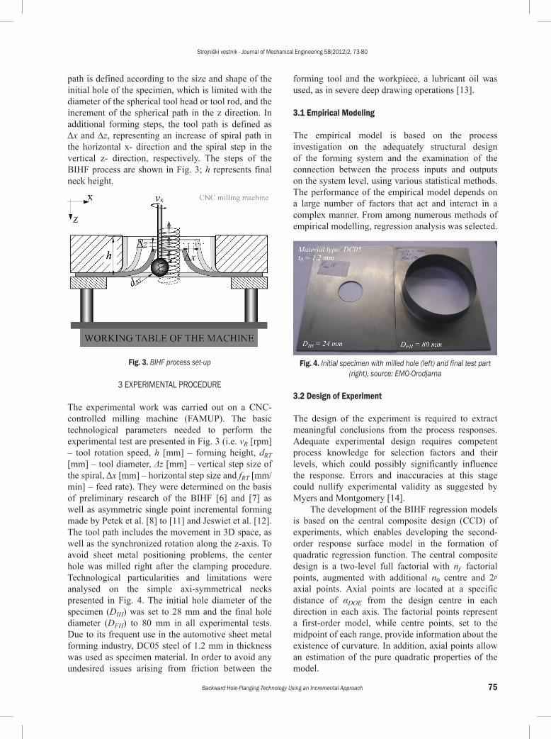
path is defined according to the size and shape of the initial hole of the specimen, which is limited with the diameter of the spherical tool head or tool rod, and the increment of the spherical path in the z direction. In additional forming steps, the tool path is defined as Dx and Dz, representing an increase of spiral path in the horizontal x- direction and the spiral step in the vertical z- direction, respectively. The steps of the BIHF process are shown in Fig. 3; h represents final neck height.
Fig. 3. BIHF process set-up
3 EXPERIMENTAL PROCEDURE
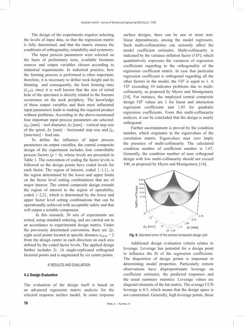
The experimental work was carried out on a CNC-controlled milling machine (FAMUP). The basic technological parameters needed to perform the experimental test are presented in Fig. 3 (i.e. vR [rpm] – tool rotation speed, h [mm] – forming height, dRT [mm] – tool diameter, Δz [mm] – vertical step size of the spiral, Δx [mm] – horizontal step size and fRT [mm/min] – feed rate). They were determined on the basis of preliminary research of the BIHF [6] and [7] as well as asymmetric single point incremental forming made by Petek et al. [8] to [11] and Jeswiet et al. [12]. The tool path includes the movement in 3D space, as well as the synchronized rotation along the z-axis. To avoid sheet metal positioning problems, the center hole was milled right after the clamping procedure. Technological particularities and limitations were analysed on the simple axi-symmetrical necks presented in Fig. 4. The initial hole diameter of the specimen (DIH) was set to 28 mm and the final hole diameter (DFH) to 80 mm in all experimental tests. Due to its frequent use in the automotive sheet metal forming industry, DC05 steel of 1.2 mm in thickness was used as specimen material. In order to avoid any undesired issues arising from friction between the
forming tool and the workpiece, a lubricant oil was used, as in severe deep drawing operations [13].
3.1 Empirical Modeling
The empirical model is based on the process investigation on the adequately structural design of the forming system and the examination of the connection between the process inputs and outputs on the system level, using various statistical methods. The performance of the empirical model depends on a large number of factors that act and interact in a complex manner. From among numerous methods of empirical modelling, regression analysis was selected.
Fig. 4. Initial specimen with milled hole (left) and final test part (right), source: EMO-Orodjarna
3.2 Design of Experiment
The design of the experiment is required to extract meaningful conclusions from the process responses. Adequate experimental design requires competent process knowledge for selection factors and their levels, which could possibly significantly influence the response. Errors and inaccuracies at this stage could nullify experimental validity as suggested by Myers and Montgomery [14].
The development of the BIHF regression models is based on the central composite design (CCD) of experiments, which enables developing the second-order response surface model in the formation of quadratic regression function. The central composite design is a two-level full factorial with nf factorial points, augmented with additional n0 centre and 2p axial points. Axial points are located at a specific distance of αDOE from the design centre in each direction in each axis. The factorial points represent a first-order model, while centre points, set to the midpoint of each range, provide information about the existence of curvature. In addition, axial points allow an estimation of the pure quadratic properties of the model.
Strojniški vestnik - Journal of Mechanical Engineering 58(2012)2, 73-80
76 Petek, A. – Kuzman, K.
The design of the experiments requires selecting the levels of input data, so that the regression matrix is fully determined, and that the matrix ensures the conditions of orthogonality, rotatability and symmetry.
The input process parameters were selected on the basis of preliminary tests, available literature sources and output variables chosen according to industrial requirements. In industrial practice, how the forming process is performed is often important; therefore, it is necessary to define neck height and its thinning and consequently, the limit forming ratio (LFR), since it is well known that the size of initial hole of the specimen is directly related to the fracture occurrence on the neck periphery. The knowledge of these output variables and their most influential input parameters leads to making the required product without problems. According to the above-mentioned four important input process parameters are selected: dRT [mm] – tool diameter, Δz [mm] – vertical step size of the spiral, Δx [mm] – horizontal step size and fRT [mm/min] – feed rate.
To define the influence of input process parameters on output variables, the central composite design of the experiment includes four controllable process factors (p = 4), whose levels are presented in Table 1. The convention of coding the factor levels is followed so the design points have coded levels for each factor. The region of interest, coded {‒1,1}, is the region determined by the lower and upper limits on the factor level setting combinations that are of major interest. The central composite design extends the region of interest to the region of operability, coded {‒2,2}, which is determined by the lower and upper factor level setting combinations that can be operationally achieved with acceptable safety and that will output a testable component.
In this research, 30 sets of experiments are sorted, using standard ordering, and are carried out in an accordance to experimental design matrix. Under the previously determined convention, there are 2p, eight axial points located at specific distance αDOE = 2 from the design centre in each direction on each axis defined by the coded factor levels. The applied design further includes 2p, 16 single-replicated orthogonal factorial points and is augmented by six centre points.
4 RESULTS AND EVALUATION
4.1 Design Evaluation
The evaluation of the design itself is based on an advanced regression matrix analysis for the selected response surface model. In some response
surface designs, there can be one or more non-linear dependencies, among the model regressors. Such multi-collinearities can seriously affect the model coefficient estimates. Multi-collinearity is indicated by the variance inflation factor (VIF), which quantitatively expresses the variances of regression coefficients regarding to the orthogonality of the regression coefficient matrix. In case that particular regression coefficient is orthogonal regarding all the other factors in the model, the VIF is equal to 1. A VIF exceeding 10 indicates problems due to multi-collinearity, as proposed by Myers and Montgomery [14]. For instance, the employed central composite design VIF values are 1 for linear and interaction regression coefficients and 1.05 for quadratic regression coefficients. From this multi-collinearity analysis, it can be concluded that the design is nearly orthogonal.
Further ascertainment is proved by the condition number, which originates in the eigenvalues of the correlation matrix. Eigenvalues near zero imply the presence of multi-collinearity. The calculated condition number of coefficient number is 1.67. Generally, the condition number of near orthogonal design with low multi-collinearity should not exceed 100, as proposed by Myers and Montgomery [14].
Fig. 5. Standard error of the central composite design plot
Additional design evaluation criteria relates to leverage. Leverage has potential for a design point to influence the fit of the regression coefficients. The disposition of design points is important in determining model properties. Particularly remote observations have disproportionate leverage on coefficient estimates, the predicted responses and the usual summary statistics. Leverage values are diagonal elements of the hat matrix. The average CCD leverage is 0.5, which means that the design space is not constrained. Generally, high leverage points, those
Strojniški vestnik - Journal of Mechanical Engineering 58(2012)2, 73-80
77Backward Hole-Flanging Technology Using an Incremental Approach
close to 1, should be avoided as proposed by Myers and Montgomery [14].
The last considered design evaluation criterion refers to G- efficiency, which is the average prediction variance as a percentage of the maximum prediction variance. The aim of good design is G- efficiency of at least 50%, as proposed by Krajnik et al. [15]. In the applied design, the calculated G- efficiency from the design points is 85.7%, which is adequate.
In addition to numerical statistics for design evaluation, it is useful to plot the standard error over the investigated design space, which measures the estimation accuracy of mean arithmetic prediction (Fig. 5). The plot shows how the error in the predicted response varies over the design space. Because of fewer experiments outside the main experimental interest (levels ‒1 and 1), a considerable increase in design error can be noticed in the operative region, which has to be taken into account during response prediction. The shape of the plot depends only on the design points and the polynomial being fit. Fig. 5 shows circular contours and a symmetrical 3D shape indicating rotatable design. Another noticed feature is the relatively low error around the centre points.
4.2 Regression Models of the Selected Output Variables
From the design evaluation, it could be established that the regression matrix is fully determined. Such design of experiments enables developing the quadratic regression models. Before that, it is necessarily to check the validity of the statistical assumptions on which the least square method basis.
The checking of the model adequacy refers to various residual diagnostics that are able to identify the eventual least square assumption violations. The commonly used approach is to examine the residuals. For this reason, normal probability plots have been checked for all responses. Their residuals all plot approximately along a straight line; hence, the normality assumptions are satisfied.
Another graphical diagnostics is a plot of studentized residuals versus predicted responses. The residuals of all responses scatter randomly, suggesting
that the variance of observations is constant for all values. The random patterns therefore indicate model adequacy.
The model fitting is the next important step and has to provide an adequate approximation to the investigated process. It uses a special decomposition algorithm on the design matrix, which is used for solving various linear algebraic equations and the least squares problems. The model fitting assessment is based on several standard statistics. The deterministic coefficient R2 of multiple determinations estimates the fraction of total variation in the data accounted by the model. For the designed experiments, it is better to employ adj-R2 statistics, which is adjusted to the number of terms in the model relative to the number of design points, and measures the amount of variation about the mean explained by the model. According to Myers and Montgomery [14], it can be expressed as:
adj R SSE DFESST DFT
− = −2 1 //
, (1)
where SSE is the sum of squared errors, SST the total sum of squares, DFE the error of degree of freedom and DFT the total degree of freedom.
The determination of significant model degree and factor effects is based on the F-value and the P-value, calculated with ANOVA. These two numerical values imply a significance of a model degree and particular linear, quadratic or interaction terms. Usually, P-values smaller than 0.05 show that the particular terms of a model have a significant effect on the response.
Full regression models developed many times include some model terms that are not significant. In these cases, model reduction is applied, which eliminates those terms in such a way that statistical hierarchy is not violated. For statistical reasons, models that contain subsets of all possible effects should preserve hierarchy. A model is hierarchal if the presence of quadratic terms and interactions requires the inclusion of all linear terms contained within those of a higher order, even if they do not appear to be significant on their own. The automatic, computer-aided model reduction follows the stepwise
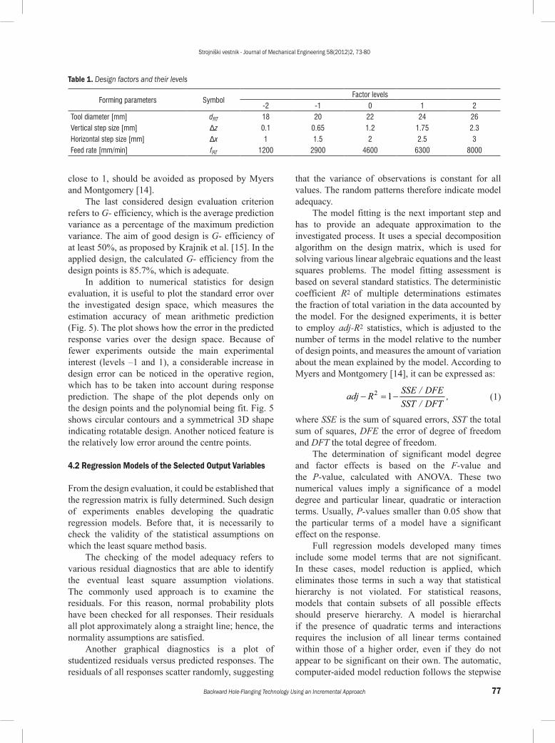
Table 1. Design factors and their levels
Forming parameters SymbolFactor levels
-2 -1 0 1 2Tool diameter [mm] dRT 18 20 22 24 26Vertical step size [mm] Δz 0.1 0.65 1.2 1.75 2.3Horizontal step size [mm] Δx 1 1.5 2 2.5 3Feed rate [mm/min] fRT 1200 2900 4600 6300 8000
Strojniški vestnik - Journal of Mechanical Engineering 58(2012)2, 73-80
78 Petek, A. – Kuzman, K.
regression algorithm, which combines the forward and the backward model term elimination procedures. In the stepwise procedure, all regressions are entered into the model at each step, according to their partial t value and are removed one at a time if their P-value is less than the specified cut-off value, usually set to 0.1. Regression surface models have been developed in the form of reduced polynomials in terms of actual factors. The first is used to predict maximal neck height at particular design points (adj-R2 = 0.96) and is expressed as:
h d x z
d x zRT
RT
= + ⋅ + ⋅ − ⋅ −
− ⋅ − ⋅ + ⋅
19 8 0 67 0 98 4 3
0 02 0 3 0 792 2 2
. . . .
. . .
∆ ∆
∆ ∆ ++ ⋅ ⋅0 37. .∆ ∆x z (2)
The second is used to predict average neck thickness at particular design points (adj‒R2 = 0.8) and is expressed as:
t d x
z d zneck RT
RT
= − ⋅ − ⋅ +
+ ⋅ + ⋅ − ⋅
1 9 0 079 0 047
0 13 1 9 0 0292 2
. . .
. . . .
∆
∆ ∆ (3)
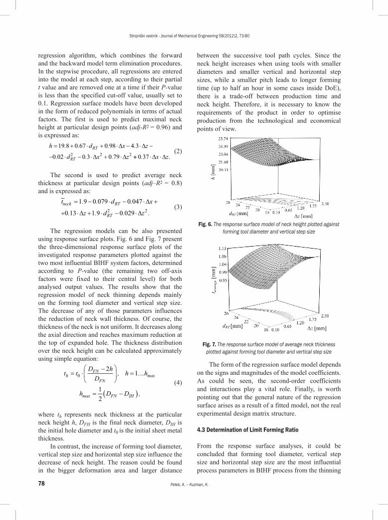
The regression models can be also presented using response surface plots. Fig. 6 and Fig. 7 present the three-dimensional response surface plots of the investigated response parameters plotted against the two most influential BIHF system factors, determined according to P-value (the remaining two off-axis factors were fixed to their central level) for both analysed output values. The results show that the regression model of neck thinning depends mainly on the forming tool diameter and vertical step size. The decrease of any of those parameters influences the reduction of neck wall thickness. Of course, the thickness of the neck is not uniform. It decreases along the axial direction and reaches maximum reduction at the top of expanded hole. The thickness distribution over the neck height can be calculated approximately using simple equation:
t t
D hD
h h
h D D
hFN
FN
FN IH
= ⋅−
=
= −( )
02
1
12
, ....
,
max
max
(4)
where th represents neck thickness at the particular neck height h, DFH is the final neck diameter, DIH is the initial hole diameter and t0 is the initial sheet metal thickness.
In contrast, the increase of forming tool diameter, vertical step size and horizontal step size influence the decrease of neck height. The reason could be found in the bigger deformation area and larger distance
between the successive tool path cycles. Since the neck height increases when using tools with smaller diameters and smaller vertical and horizontal step sizes, while a smaller pitch leads to longer forming time (up to half an hour in some cases inside DoE), there is a trade-off between production time and neck height. Therefore, it is necessary to know the requirements of the product in order to optimise production from the technological and economical points of view.
Fig. 6. The response surface model of neck height plotted against forming tool diameter and vertical step size
Fig. 7. The response surface model of average neck thickness plotted against forming tool diameter and vertical step size
The form of the regression surface model depends on the signs and magnitudes of the model coefficients. As could be seen, the second-order coefficients and interactions play a vital role. Finally, is worth pointing out that the general nature of the regression surface arises as a result of a fitted model, not the real experimental design matrix structure.
4.3 Determination of Limit Forming Ratio
From the response surface analyses, it could be concluded that forming tool diameter, vertical step size and horizontal step size are the most influential process parameters in BIHF process from the thinning
Strojniški vestnik - Journal of Mechanical Engineering 58(2012)2, 73-80
79Backward Hole-Flanging Technology Using an Incremental Approach
and neck height points of view. Indeed, appropriate selection of that process parameter would lead to determine limit forming ratio (LFR) which can be expressed as:
LddFRf
i= , (5)
where df represents final hole diameter and di the initial hole diameter of the workpiece that can be produced without failure. Necking or tearing mostly occurs due to the excessive circumferential strain, caused by tensile stresses induced in the edge of the neck. It should be mentioned that the increase of forming ratio directly influences the increase of deformation. The highest strains occur in the periphery of the expanded hole where failure usually begins.
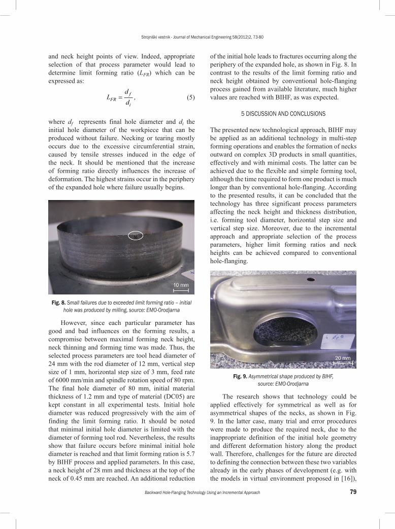
Fig. 8. Small failures due to exceeded limit forming ratio – initial hole was produced by milling, source: EMO-Orodjarna
However, since each particular parameter has good and bad influences on the forming results, a compromise between maximal forming neck height, neck thinning and forming time was made. Thus, the selected process parameters are tool head diameter of 24 mm with the rod diameter of 12 mm, vertical step size of 1 mm, horizontal step size of 3 mm, feed rate of 6000 mm/min and spindle rotation speed of 80 rpm. The final hole diameter of 80 mm, initial material thickness of 1.2 mm and type of material (DC05) are kept constant in all experimental tests. Initial hole diameter was reduced progressively with the aim of finding the limit forming ratio. It should be noted that minimal initial hole diameter is limited with the diameter of forming tool rod. Nevertheless, the results show that failure occurs before minimal initial hole diameter is reached and that limit forming ration is 5.7 by BIHF process and applied parameters. In this case, a neck height of 28 mm and thickness at the top of the neck of 0.45 mm are reached. An additional reduction
of the initial hole leads to fractures occurring along the periphery of the expanded hole, as shown in Fig. 8. In contrast to the results of the limit forming ratio and neck height obtained by conventional hole-flanging process gained from available literature, much higher values are reached with BIHF, as was expected.
5 DISCUSSION AND CONCLUSIONS
The presented new technological approach, BIHF may be applied as an additional technology in multi-step forming operations and enables the formation of necks outward on complex 3D products in small quantities, effectively and with minimal costs. The latter can be achieved due to the flexible and simple forming tool, although the time required to form one product is much longer than by conventional hole-flanging. According to the presented results, it can be concluded that the technology has three significant process parameters affecting the neck height and thickness distribution, i.e. forming tool diameter, horizontal step size and vertical step size. Moreover, due to the incremental approach and appropriate selection of the process parameters, higher limit forming ratios and neck heights can be achieved compared to conventional hole-flanging.
Fig. 9. Asymmetrical shape produced by BIHF, source: EMO-Orodjarna
The research shows that technology could be applied effectively for symmetrical as well as for asymmetrical shapes of the necks, as shown in Fig. 9. In the latter case, many trial and error procedures were made to produce the required neck, due to the inappropriate definition of the initial hole geometry and different deformation history along the product wall. Therefore, challenges for the future are directed to defining the connection between these two variables already in the early phases of development (e.g. with the models in virtual environment proposed in [16]),
Strojniški vestnik - Journal of Mechanical Engineering 58(2012)2, 73-80
80 Petek, A. – Kuzman, K.
with the aim of producing the required asymmetrical necks with minimal trial and error procedures.
6 ACKNOWLEDGEMENTS
The authors are grateful to the Slovene Ministry of Higher Education, Science and Technology for their financial assistance under the ARRS project “Robust small-batch forming processes L2-1111”.
7 REFERENCES
[1] Johnson, W., Chitkara, N., Minh, H. (1977). Deformation mode and lip fracture during hole-flanging of circular plates of anisotropic materials. Journal of Engineering for Industry - Transactions of the ASME, vol. 99, 738-748, DOI:10.1115/1.3439307.
[2] Spur, G., Stoferle, T. (1985). Handbuch der Fertigungstechnik, Umformen und Zerteilen, Carl Hanser Verlag, Munchen, Wien.
[3] Huang, Y.M., Chien, K.H. (2001). The formability limitation of the hole-flanging process. Journal of Materials Processing Technology, vol. 117, 43-51, DOI:10.1016/S0924-0136(01)01060-3.
[4] Leu, D.K. (1996). Finite element simulation of hole-flanging process of circular sheets of anisotropic materials. International Journal of Mechanical Sciences, vol. 38, p. 917-933, DOI:10.1016/0020-7403(95)00090-9.
[5] Cui, Z., Gao, L. (2010). Studies on hole-flanging process using multistage incremental forming. CIRP Journal of Manufacturing Science and Technology, vol. 2, p. 124-128, DOI:10.1016/j.cirpj.2010.02.001.
[6] Suholežnik, R. (2010). Hauling of sheet metal throat articles on small-scale production conditions. Undergraduate thesis, University of Ljubljana, Ljubljana.
[7] Petek, A., Kuzman, K., Fijavž, R. (2011). Backward drawing of necks using incremental approach. Key Engineering Materials, p. 105-112, DOI:10.4028/www.scientific.net/KEM.473.105.
[8] Petek, A. (2009). The definition of stable technological window by incremental sheet metal forming. PhD Thesis, University of Ljubljana, Ljubljana.
[9] Petek, A., Kuzman, K., Suhač, B. (2009). Autonomous on-line system for fracture identification at incremental sheet forming. CIRP Annals - Manufacturing Technology, vol. 58, no. 1, p. 283-286.
[10] Petek, A., Podgornik, B., Kuzman, K., Čekada, M., Waldhauser, W., Vižintin, J. (2008). The analysis of complex tribological system of single point incremental sheet metal forming. Strojniški vestnik - Journal of Mechanical Engineering, vol. 54, no. 4, p. 266-273.
[11] Petek, A., Zaletelj, V., Kuzman, K. (2009). Particularities of an incremental forming application in multi-layer construction elements. Strojniški vestnik - Journal of Mechanical Engineering, vol. 55, no. 7-8, p. 423-426.
[12] Jeswiet, J., Micari, F., Hirt, G., Bramley, A., Duflou, J., Allwood, J. (2005). Asymmetric single point incremental forming of sheet metal. Annals of CIRP, vol. 54, no. 2, p. 623-650, DOI:10.1016/S0007-8506(07)60021-3.
[13] Volk, M., Nardin, B., Dolšak, B. (2011). Application of numerical simulation in the deep-drawing process and the holding system with segments’ inserts. Strojniški vestnik - Journal of Mechanical Engineering, vol. 57, no. 9, p. 697-703.
[14] Myers, R.H., Montgomery, D.C. (2002). Response surface methodology, process and product optimization using designed experiments. John Wiley & Sons Inc., New York.
[15] Krajnik, P., Kopač, J., Sluga, A. (2005). Design of grinding factors based on response surface methodology. Journal of Materials Processing Technology, vol. 162-163, p. 629-636, DOI:10.1016/j.jmatprotec.2005.02.187.
[16] Manić, M., Miltenović, V., Stojković, M., Banić, M. (2010). Feature models in virtual product development. Strojniški vestnik - Journal of Mechanical Engineering, vol. 56, no. 3, p. 169-178.