Embed Size (px)
Citation preview

... ~ ":· .
ORNL/MIT·338
Separation of Alcohoi·Water Mixtures Using Salts
John C. Card Luann M. Farrell
DO NOT MICROFILM COVER

DISCLAIMER
This report was prepared as an account of work sponsored by an agency of the United States Government. Neither the United States Government nor any agency Thereof, nor any of their employees, makes any warranty, express or implied, or assumes any legal liability or responsibility for the accuracy, completeness, or usefulness of any information, apparatus, product, or process disclosed, or represents that its use would not infringe privately owned rights. Reference herein to any specific commercial product, process, or service by trade name, trademark, manufacturer, or otherwise does not necessarily constitute or imply its endorsement, recommendation, or favoring by the United States Government or any agency thereof. The views and opinions of authors expressed herein do not necessarily state or reflect those of the United States Government or any agency thereof.

DISCLAIMER
Portions of this document may be illegible in electronic image products. Images are produced from the best available original document.

Printed in the United States of America. Available from National Technical Information Service
U .S. Department of Commerce 5285 Port Royal Road , Springfield , Virginia 22161
NTIS price codes- Printed Copy: A04; Microfiche A01
This report was prepared as an account of work sponsored by an agency of the United States Government. Neither the United States Government nor any agency thereof, nor any of the ir employees, makes any warranty , express or impl ied, or assumes any legal liability or responsibility for the accuracy, completeness, or usefulness of any information , apparatus, product, or process disclosed, or represents that its use would not infringe privately owned rights. Reference herein to any specif ic commercial product, process, or service by trade name, trademark , manufacturer, or otherwise, does not necessarily constitute or imply its endorsement, recommendation , or favoring by the United States Government or any agency thereof. The views and op inions of authors expressed herein do not necessarily state or reflect those of the United States Government or any agency thereof.
..
;.
I - ---c·------ ~----- -----~
I ORNL/MIT -338
I Contract No. W-7405-eng-26
. ORNL/MI'_f--3 38 · ~ . . . ~
DE82 013346
CHEMICAL TEGHNOIO~Y nTVTSTON
SEPARATION OF ALCOHOL-WATER MIXTURES USING SALTS
John C. Card Luann M. Farrell
Consultants: T.L. Donaldson, C.H. Brown, and G.W. Strandberg
··:·.~ Date Pub 1 i shed - April 1982 OO®"n[;\E ·: v~llll~~~ ®It: 'fl'allM$ ~\E~©~fft ~ .. m:. !~G~~~P®~ ~ 8illli'<l~ ~If ~ 'l\'~ -N·~·--··"-- t - · _ -~~;~e~ ~~·m~ t~e b®S · »t hal$ ~!lllll:'m re~il' . r i't t~'i"' liilll'~e§dest ·~®~ie c«DI!lliU i«ll ~®t ~@ • !!;; ava~ . ""'rt• .poE&ib~e aw~nftaJilli~ g If·
Oak Ridge Station School of Chemical Engineering Practice Massachusetts Institute of Technology
C.H. Byers, Director I
Oak Ridge National Laboratory Oak Ridge, Tennessee 37830
Operated by Union Carbide Corporation
. for the Department of Energy

THIS PAGE
WAS. INTENTI 0 NALLY
LEFT BLANK

iii
ABSTRACT
Use of a salt (KF or Na2S04) to induce phase separation of alcoholwater mixtures was investigated in three process flowsheets to compare operating and capital costs with a conventional distillation process. The proce·ss feed was the Clostridia fermentation product, composed of 98 wt% water and 2 wt% solvents (70% 1-buGanol, 27% 2-propanol, and 3% ethanol). The design basis was 150 x 10 kg/y of solvents. Phase equilibria and tieline data were obtained from literature and experiments.
Three separation-process designs were developed and compar-ed by an incremental economic analysis (±30%) with the conventional separation technique using distillation alone. The cost of salt recovery for recycle was found to be the critical feature. High capital and operating costs make recovery of salt by precipitation uneconomical; however, a separation scheme using multiple-effect evaporation for salt recovery has comparable incremental capital costs ($1.72 x 10⁶ vs $1.76 x 10⁶) and lower incremental operating costs ($2.14 x 10⁶/y vs $4.83 x 10⁶/y) than the conven-tional separation process. ·

THIS PAGE
WAS INTENTIONALLY
LEFT BLANI<

.•
v
Contents Page
1. Summary . . . . . . . . . . . . . . . . . . . . . . . . . . . . . . . . . . . . . . . . . . . . . . . . . . . . . . 1 2 . I n trod u c t i on . . . . . . . . . . . . . . . . . . . . . . . . . . . . . . . . . . . . . . . . . . . . . . . . . 2
2.1 Objective . . . . . . . . . . . . . . . . . . . . . . . . . . . . . . . . . . . . . . . . . . . . . . 2 2. 2 Background . .. . . . . . . . . . . . . . . . . . . . . . . . . . . . . . . . . . . . . . . . . . . . 2
2. 2. 1 Convent i ana 1 Separation Methods . . . . . . . . . . . . . . • • . . 2 2.2.2 Proposed Separation Method . ..................... 8
2. 3 Model Process Feed stream ..... •........................... 8 .2.4 Phase Equilibria ........................................ 10
2.4.1 Choice of Solvent Composition .................... 10
2.4.2 Effect of Salt on the Butanol-Water-Salt Phase Equilibrium . . . . . . . . . . . . . . . . . . . . . . . . . . . . . . . . . . . . . . 14
3. Experimentation .............................................. 16
4.
5.
6.
7.
3.1 Apparatus and Procedure ................................. 16 3.2 Results ................................................. 16 3. 3 Ana 1 ys is . . . . . . . . . . . . . . . . . . . . . . . . . . . . . . . . . . . . . . . . . . . . . . . . 19 Separation-Process Design ................................... . 4.1 Design Variables and Assumptions; ...................... . 4~2 Process-Design Results ................•.................
4.2.1 Flowsheet Descriptions .......................... . 4.2.2 Equipment Sizing and Costing .................... .
4.3 Overall Mass and Heat Balances ......................... . Comparison of Proposed Pror.P.sses with Conventional Process .. . Conclusions ................................................. . Recommendations
19
19 22 22 23 26
26
30
30 8 .. Acknowledgments .............................•................ 30 9. Appendix ............ ; ........................................ 31
9.1 Physical Properties ..................................... 31 9.2 Sample Calculations ..................• ,,,., ............. 33 9. 3 Nomenclature ................. ·........................... 48 9.4 Literature References ................................... 50

1
1. SUMMARY
Recently much research has focused on bioconversion as a means of producing alcohols and chemical feedstocks from renewable resources. Although several separation techniques, including extractive and azeotropic distillation,can separate alcohol-water mixtures, lower cost separation techniques are needed to improve bioconversion process economics. T .L. Donaldson,; Chemical Technology Division, proposed using a salt to effect a phase separation in the alcohol-water mixtures. A concentrated alcoholrich phase could be formed in a single step and would result in smaller downstream distillation columns using less energy.
To ~valuate this proposal, a well-known system containing several alcohols was chosen for investigation, namely the neutral-solvent product from Clostridia fermentation. The fermentation product studied was a mixture of 98 wt %water and 2 wt % solvents, composed of 70% 1-butanol, 27% 2-propanol, and 3% ethanol. A literature survey of phase-equilibria data was conducted to determine the effect of a wide variety of salts on the phase equilibrium of this system. Based on this survey, KF and Na2S04 were identified as effective salts for producing the desired phase separation. Since alcohol/water/salt phase-equilibrium data for these two salts were available for ethanol and 2-propanol, but not 1-butanol, these latter data were determined experimentally. Equilibrium-tieline data for the 1-butanol/water/salt system were estimated for design calcul~tions, based on the available tieline data for the propanol and ethanol systems.
Utilizing these data, three alternative process designs were developed and compared economically with the conventional separation process for this system. An incremental economic analysis (±30% accuracy) was performed in which only the features of the four processes that differed were compared; all other costs were assumed equal. All processes were based on a net-solvents production of 150 x 106 kg/y.
The cost of salt recovery was found to be the dominant feature in comparisons of the three proposed processes. One process using Na2S04, based on precipitation for salt recovery, was found to have higher incremental capital costs ($4.26 x 10⁶ versus $1.76 x 10⁶) and much higher incremental operating costs ($165.4 x 10⁶/y versus $4.83 x 10⁶/y) than the conventional separation. These high operating costs resulted from replacing the large quantities of salt which were unrecoverable by precipitation alone.
Multiple-effect evaporation was found to be a much more economical means of salt recovery. A process design using KF and multiple-effect evaporation for salt recovery had incremental capital costs comRarable with the conventional separation ($1.72 x 10⁶ versus $1.76 x 10⁶) and much more favorable incremental operating costs ($2.14 x 10⁶/y versus $4.83 x 10⁶/y). Based on these results, recommendations are made to optimize the proposed process for possible use in alcohol recovery from Clostridia fermentation, and also to investigate the application of this separation technique to other organic/aqueous systems.

-2
2. INTRODUCTION
2.1 Objective
Our objective-was to develop a separation process that uses salt to separate alcohol-water mixtures, and to compare this process economically with traditional separation schemes. This preliminary evaluation was to be a study estimate of probable error up to ±30% (1). To achieve this objctive, it was necessary to: -
1. Develop criteria for choosing an effective salt, based on a literature search of phase-equilibrium data for alcohol/water/salt systems.
2. Obtain laboratory phase-equilibrium data (phase envelope and tielines) to supplement the data not available in the literature.
3. Design a separation process based on the equilibrium data obtained.
4. Compare the economics of this process with that of a conventional separation in an incremental economic analysis based on a total-alcohols production of 150 x 106 kg/y, assuming 95% product purity and 95% solvents recovery.
2.2 Background
2.2.1 Conventional Separation Methods
Alcohol-water mixtures can be separated by several methods, such as distillation, extraction, or a combination of both. The lowest·cost technique for many chemicals is distillation, since many mixtures can be separated directly into pure products without further processing. However, many of the commonly encountered alcohol-water mixtures (ethanol-, propanol-, butanol-water) form azeotropes, which make separation into pure components impossible by simple distillation. In these systems, variations on simple distillation are employed to effect separation. Two such techniques are azeotropic and extractive distillation. These processes are described. in detail by McCabe and Smith (2), Treybal (3), Benedict and Rubin (4), and Smith (§_) and are summarized-here. - -
In extractive distillation a solvent not present in the mixture is added to increase the difference in volatility between the key components to be separated. The solvent is less volatile than the key components; it is fed near the top of the distillation column and is removed from the column with the bottoms (see Fig. 1). A second distillation tower is necessary for solvent recovery and purification of the second product.
Alternatively, several variations of azeotropic distillation can be used to separate alcohol-water mixtures, depending on the vapor-liquid

Makeup Solvent
Feed ----o-1
Recycle Solvent
Extractive Distillation Towe_r
Product 1
DATE
·'
.,_ __ __. ___ Product 2
Product Recovery Tower
MASSACHUSETTS INSTITUTE OF TECHNOLOGY SCHOOL OF CHEMICAL ENGINEERING PRACTICE
AT· . OAK RIDGE NATIONAL LABORATORY
SEPARATION OF MIXTURE BY EXTRACTIVE DISTILLATION
FIG.
1 0-16-81
w

4
equilibrium characteristics of the system involved. For example, the 1-butanol/water system exhibits a miscibility gap between liquid butanol mole fractions 0.02 and 0.45 (see Fig. 2a). At temperatures below approximately 92°C, any 1-butanol/water mixture with butanol mole fraction in this range will spontaneously separate into two phases, whose mole fractions are given by the endpoints. This property of the 1-butanol/water system can be exploited in an azeotropic distillation scheme. Since the miscibility gap crosses the azeotrope (note the intersection of the equilibrium curve with the X-V line in Fig. 2b), the alcohol and water can be separated by a simple, two-column distillation schem~ as shown in Fig. 3a. In this design, the butanol column operates to the right of the azeotropic composition of the vapor-liquid equilibrium (VLE) curve, shown in Fig. 3b, separating the butanol-water azeotrope from pure butanol. The water column operates to the left of the azeotropic composition in the VLE diagram in Fig. 3b, separating the butanol-water azeotrope from pure water.
F{gure 3b is a graphical representation of the operation of these columns on the VLE diagram by a McCabe-Thiele analysis (3). The azeotrope is the overhead product of both columns since its boiling point is below that of either pure component. The azeotrope is condensed and fed to a decanter, where it spontaneously separates into two phases. The butanol-rich phase is refluxed to the top stage of the butanol column, while the water-rich phase is refluxed to the top stage of the water column. It must be stressed that this process is effective only because the 1-butanol/water system forms a heterogeneous azeotrope, i.e., one that spontaneously separates into two phases. If this were not the case, a decanter would not be sufficient to separate the overhead azeotrope product, and another, more expensive, separation process would be required.
Other simple alcohols, such as ethanol and propanol do not form heterogeneous azeotropes in water, and so more-complicated separation schemes are required. Ethanol, like 2-propanol and 1-butanol, forms a minimum-boiling azeotrope with water. To effect separation, a distillation scheme such as that of Fig. 4 can be used. Benzene is added to the ethanol-water mixture. This forms a minimum-boiling ternary azeotrope with ethanol and wate~which boils at a lower temperature than the ethanol/ water binary azeotrope. The ternary azeotrope contains a higher ratio of water than the ethanol/water azeotrope. The. ternary azeotrope flows overhead from the primary column, removing all the water and benzene, leaving pure ethanol as the bottoms product. When the overhead is condensed and sent to a decanter, it spontaneously separates into a two-phase mixture. The upper benzene-rich phase is returned as reflux to the primary column, while the lower water-rich phase is fed to a secondary column, which also produces the ternary azeotrope as the overhead product. The bottom product from the secondary column is a mixture of alcohol and water, which is split in a third tower into a bottom product of pure water and an overhead product which is the ethanol-water binary azeotrope. This overhead stream is recycled to the primary column. This process is made effective only by use of benzene, or a similar substance, to push the ethanol-water feed composition past the binary azeotropic composition.

.. L
B E QJ c. ~ 1-
5
120,---~---,----~~-r----r---~---,----~--~---,
110
9o
80
0
IITITiiscible Region
0.2 0.4 0.6
Mole Fraction 1-Butanol
2a
0.8 1.0
l.Or---r---r---~--~--,---,---~---r~-r--~
c: 0 ...
0.8
~ 0.6 ~ QJ
0 "" QJ
~ 0.4 Q.
L
2b.
! r·~------~------~~ 0.2
Butanol-Rich Phase
Liquid-Phase Mole Fraction, x8
MASSACHUSETTS INSTITUTE Of TECHNOLOGY SCHOOL 0~ CMfiMICAL EHGINii&RING PRACTICE
AT OAK RIDGE NATIONAL LA.BORATORY
1-BUTANOL/WATER EQUILIBRIUM DATA ILLUSTRATING THE MISCIBILITY GAP
CUTfi
10-17·01

From Column 59% Water 41% Butanol
Bu tano 1 Co 1 umn
0.8
_.J:Q
.; 0 ...
0.6 u .. ·.!: .,
0
"" ~ '" 0.4 "" Q.
' ~ c. .. >
0.2
Butanol
Water Column
6
Butanol-Water Azeotrope
Water Co 1 umn
Water
3a
Butanol Column
'X
0.6 0.8 1.0 Liquid-Phase Mole Fraction, XB
3b
MASSACHUSETTS INSTITUTE OF TECHNOLOGY
SCHOOL OF CHEMICAL ENGINEERING PRACTICE Af
OAK RIDGE NATIONAL LABORATORY
SEPARATION OF BUTANOL FROM WATER BY AZEOTROP!C OIST!LLATION
DATE
10-16-8

F eed----ol.--~
Priman Column
Pure Ethano 1
Ternary Azeotrope
Reflux
Makeup Berizene
Secondary Column Aqueous Ethanol
Alcohol-Water Aze.otrope
MA$SACHUSETTS INSTITUTE OF TECHNOLOGY
SCHOOL OF CHEMICAL ENGINEERING PRACTICE AT
OAK RIDGE NATIONAL LABORATORY
SEPARATION OF ETHANOL FROM WATER BY AZEOTROPIC DISTILLATION WITH
BENZENE AS THE AZEOTROPE BREAKER
DATE IDRAWN BY ~ILE NO. ~IF I G. 10-16-81 JCC EPS-X-338 . 4 I
~-------------------------------------------------------------A--------~-------L------~~------~1

8
2.2.2 Proposed Sepa~ation Method
An alternative process, proposed by T.L. Donaldson (6), is to effect the separation of the· alcohol/·water mixture into two immiscible phases by the addition of a salt instead of a solvent. The salt decreases the solubility of the alcohol in water, resulting in the formation of a water-rich phase and an alcohol-rich phase. As with solvent processing in extractive or azeotropic distillation, salt processing is required in this technique. However, only the alcohol-rich phase would need to pass through distillation columns for separation; the water-rich phase would be removed in a decanter previous to the columns, as shown in Fig. 5. This could result in smaller downstream distillation columns and possibly lower energy costs. This assumes that the salt will have a very low solubility in the organic phase.
For butanol/water mixtures, where a mi sci bil ity gap a 1 ready exists, the addition of salt would cause the gap to expand, and thus form a richer alcohol-rich phase and a leaner alcohol-lean phase. This would reduce the number of equilibrium stages needed in both columns of Fig. 3.
For ethano l;.water and propano 1/water mixtures, where no mi sci bil i ty gap exists, the addition of salt would also cause the formation of an alcohol-rich phase and an alcohol-lean phase. If a salt could be found that would push the composition of th.e alcohol-rich phase past the azeotropic composition, then pure alcohol and pure water could be obtained by using only two distillation columns. In any case, the absolute flow rates in the distillation columns would be reduced, which could result in capital and energy savings and in less energy consumption. To evaluate the potential of this separation technique, a model process feedstream was investigated.
2.3 Model Process Feedstream
The feedstream investigated was a mixture of 98 wt % water and 2 wt % solvents, composed of 70 wt% 1-butanol, 27 wt% 2-propanol, and 3 wt% ethanol. This mixture is typical of the fermentation products of the bacteria Clostridia. Several strains of' Clostridia can be used to ferment many diverse forms of biomass including wood wastes, corn, and molasses to produce neutral solvents, such as 1-butanol, 2-propanol, acetone, and ethanol (7). From World War I through the late 1950s Clostridia fermentations were used commercia·l-ly to produce 1-butano I and acetone (8). The loss of inexpensive Cuban molasses feedstocks shifted U.S. production of neutral solvents to petroleum-based processes. However, rising petroleum costs and decreasing bioconversion costs may again make Clostridia fermentation economically attractive (~).
The fermentation products of the Clostridia system were chosen for investigation, not only because the Clostridia system is well-known and is of general interest, but also because a wide variety of alcohols are produced. Several investigators are focusing on a strain of Clostridium
•
,

Salt Ma:<eup
r Alcohol-Rich Phase to Distil.lation
Alcohol/Water . _..
Decanter Mixture
Water...:Rich Phase
. - Sait Processing Salt
MASSACHUSETTS INSTITUTE OF TECHNOLOGY .. . SCHOOL OF CHEMICAL ENGINEERING PRACTICE
AT OAK RIDGE NATIONAL LABORATORY
Water SEPARATION OF ALCOHOUWATER MIXTURE USING SALT
DATE II DRAWN BY l 0-16-81 LMF v~ILE NO. ~riG. EPS-X-338 5

10
(Clostridia saccharoacetobutylicum) that·produces 1-butanol, acetone, and ethanol. Another strain of Clostridium (Clostridia acmylo-saccha.robutylpropylicum) ferments to 1-butanol, 2-propanol, and ethanol. It is a simulated fermentation broth of the latter strain that was investigated in this study. Thus, the effectiveness of salt in separating 1-butanol, 2-propanol, and ethanol/water systems was investigated. These results
were then compared with similar systems in different applications.
2.4 Phase Equilibria
2.4. 1 Choice of Solvent Composition
The vapor-liquid equilibria for the 1-butanol/water system is presented in Fig. 2b. As previously discussed, a miscibility gap in the aqueous mixture exists between butanol mole fractions of 0.02 and 0.45. This results in the formation of a water-rich phase and a butanol-rich phase,~as labeled on Fig. 2b. If a third component, such as NaCl, is added to the butanol/water mixture, the phase equilibrium of the system can be represented in a ternary diagrarm, as shown in Fig. 6. These data were obtained from· Stephen and Stephen (10). The corners of the triangle represent pure components, the edges-are binary mixtures (weight percents), while any point within the triangle is a three-component mixture. The miscibility gap can also be observed on this diagram. It extends from point A to point B, where A is the water-rich phase, and 8 is the butanol-rich phase ..
If yet a fourth component such as acetone is added to this system, the phase equilibrium of the system can be represented by extending Fig. 6 into the third dimension, as shown in Fig. 7a. The quaternary diagram of Fig. 7a illustrates the phase equilibria only on the faces of the pyramid; no attempt was made to depict the three-dimensional surface within the pyramid. However, in this study the concentrations of salts and solvents are such that the points of interest within the pyramid are located very close to the faces. Therefore, to .a good approximation, the phase equilibrium curves for these quaternary compositions can be approximated by the ternary phase equilibrium curves on the faces of the pyramid. This corresponds to assuming that the minor component alcohol behaves in the same manner as the major component alcohol. Phase equilibrium data for 1-butanol/water/NaCl/acetone systems, containing 8 and. 13 wt% acetone can be estimated by slicing the pyramid along these acetone compositions as shown in Fig. 7a. These slices aie shown in Figs. Bb and 8c. A similar analysis can be conducted for the 1-butanol/water/ NaCl/2-propanol system, the results of which are presented in Figs. 7b and 8d through 8f.
In Figs. 8a through 8c, notice that for even very small amounts of ·acetone in the 1-butanol/water/NaCl/acetone system, the miscibility gap shrinks considerably. This means that to distill butanol from this system with the separation scheme of Fig. 3a, many more distillation

P 1 atm
11
1..:butano1
MASSACHUSETTS INSTITUTE OF TECHNOLOGY SCHOOL OF CHEMICAL ENGINEERING PRACTICE
. AT
OAK RIDGE NATIONAL LABORATORY
PHASE-EQUILIBRIA DATA FOR 1-BUTANOL!WATER/NaC1 SYSTEM (lQ)
DATE DRAWNBY
10-17-81 JCC 6

7a
Acetone
P 1 atm
7b
2-propanol
12
1-butano1
NaCl
Water
1-butano1
Water
NaCl
MASSACHUSETTS INSTITUTE OF TECHNOLOGY
SCHOOL OF CHEMICAL ENGINEERING PRACTICE AT
OAK RIDGE NATIONAL LABORATORY
QUATERNARY PHASE-EQUILIBRIUM DATA FOR 1-BuOH/H20/NaCl/ACETONE AND
1-BuOH/H20/NaC1/2-PrOH SYSTEMS
DATE FILE NO. FIG.
l 0- l 7-81 CEPS-X-338 7

1-~utano1
1-Butano1
1-Butano1
Ba. 0 wt % acetone Bb. B wt % acetone Be. 13 wt % acetone Bd. 0 wt % 2-propano1 Be. B wt % 2-propano1 Sf. 13 wt % 2-propano1
13
Sd
Sf
1-Butano1
1-Butano1
1-Butano1
MASSACHUSETTS INSTITUTE OF TECHNOLOGY !~Ct1Cn7u .. OF CHe:MICAL ENCINI!!e'RIHO P'RACTICE
AT OAK RIDGE NATIONAL LABORATORY
EFFECT OF ACETONE AND 2-PROPANOL ADDITION ON
1-BuOH/H20/NaC1 PHASE EQUILIBRIUM (!Q)
,CrATe
10-17-81

14
stages would be required. If more than 14 wt % acetone is present in the system, the miscibility gap disappears altogether, and a more-complicated separation scheme than that of Fig. 3a is required. In contrast, the presence of a moderate amount of 2-propanol (up to 15 wt %) in the 1-butanol/ water/NaCl/2-propanol system changes the butanol/water miscibility gap very little (Figs. 8d and Be). Thus, the butanol can be distilled from this system by the simple distillation scheme in Fig. 3a. It is for this reason that the 1-butanol/2-propanol/ethanol fermentation product was chosen over the 1-butanol/acetone/ethanol system for this study. A further simplifying assumption was made to neglect the ethanol, since it was present in very low concentration (<3 wt% of total alcohols). A more detailed discussion of the behavior of this resulting ternary system is presented in the following section.
2.4.2 Effect of Salt on the Butanol/Water/Salt Phase Equilibrium
An extensive literature search was conducted, in which phase _equilibrium data for more than 40 alcohol/water/salt systems were examined. Most of the data available pertains to ethanol systems; very little 2-propanol and almost no 1-butanol data could be·found. However, from the butanol and propanol data that are available,it was found that salts that effected good phase separation in ethanol/water systems were even more effective in propanol/water and butanol/water systems:
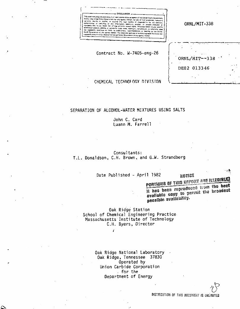
The criteria used to determine salt effectiveness are shown in Fig. 9. Phase-equilibrium data are presented for the ethanol/water/NaCl and ethanol/water/NaF systems as given by Stephen and Stephen (10). The important features of an effective salt are shown by the Nar-curve, while the NaCl curve shows a less effective salt. The upper part of the equilibrium curve should approach the pure alcohol apex of the ternary diagram as closely as possible. This results in an alcohol-rich phase of very high purity, requiring less energy consumption and fewer distillation stages to separate pure alcohol. Also, if the salt pushes this equilibrium curve to a Ji~uid alcohol ·composition richer than the composition of the alcohol/water binary azeotrope, then a single distillation column, after phase separation, can yield pure alcohol. This alcohol-rich portion of the phase envelope should be close, if not tangent, to the alcohol/water leg of the triangle. This corresponds to a very low salt concentration in the alcohol-rich phase and minimizes downstream salt-removal problems.
The lower half of the phase envelope should approach the water-rich corner of the diagram, indicating little salt addition is necessary to affect phase separation. Thus, salts with low water solubility like NaF are preferred. For example, to push a 2 wt % butanol feed within the phase envelope to achieve phase separation, 25 to 30 wt % NaCl must be added to the mixture, while less than 5 wt% is required for NaF (Fig. 9). This allows smaller salt-recovery equipment to be used, which in turn lowers capital and operating costs.
Based on these observations, several trends in effectiveness were compiled. For a given cation, the anions ranked in order of decreasing
o NaCl (a bad salt)
o NaF (a good salt)
15
P = 1 atm
Ethanol
MASSACHUSETTS INSTITUTE OF TECHNOLOGY
SCHOOL OF CHEMICAL ENGINEERING PRACTICE AT
OAK RIDGE NATIONAL LA~ORATORY
ILLUSTRATION OF A ~OOD AND A BAD SALT (lQ)
DATE DRAWN BY FIG.
10-16-81 LMF 9

16
effectiveness are F- ~SO~.> Cl- ~co=> Br-. For a given ani~n, th~ cations ranked in order of decreasing3effectivenes are K+ ~ Na > Li . Thus, the most effective salts found were KF, NaF, and Na2S04. KF and Na2so4 were investigated in this study.
3. EXPERIMENTATION
3.1 Apparatus and Procedure
The experimental apparatus consisted of two burets used for titration (100 and 10 ml),a magnetically stirred beaker, and a gas chromatograph. Stock solutions of aqueous salt mixtures were prepared. Solutions of 1, 2, 5, 10, 20, 30, 40, and 45 wt % potassium fluoride (KF) and 0.4, 2.2, 6.6, and 7.1 wt% sodium sulfate (Na2S04) were prepared.
To determine the phase envelope for a system, approximately 100 to 150 ml of a stock solution was placed in a beaker and weighed. Pure 1-butanol was titrated from the 100-ml buret into the salt solution, while the solution was constantly stirred at room t~mperature (21 to 23.5°C). 1-Butanol addition was continued slowly until the solution became cloudy temporarily. The 10-ml buret was then used to add smaller aliquots of 1-butanol. When the solution remainedcloudy after 1.-butanol addition and 2 to 3 min of stirring, titration was discontinued. To determine the point at which the solution was cloudy, printed material was placed behind the beaker. When the fine print blurred, the solution was judged to be cloudy. The volume and weight of 1-butanol added were noted and recorded. A point on the 1-butanol/waterjsalt ternary diagram was thus determined. This process was repeated for all stock solutions of the two salts used to get one side of the miscibility curve.
To obtain tieline data, a known amount of 1-butanol was added to each of the mixtures on the phase envelope. The solutions were stirred vigorously, and al1quots were taken. In the sample bottles, the solution split into two phases: a lighter 1-butanol-rich phase and a heavier water-rich phase. Samples of each phase were diluted to approximately 0.1 wt% 1-butanol and were then analyzed in a gas chromatograph (Perkin-Elmer, Model Sigma-2, with a Chr~mosorb 101 packed column operated at 150°C using a helium carrier gas).
3.2 Results
The phase diagram determined for the 1/butanol/water/KF shown in Fig. 10, and the diagram for 1-butanol/water/Na2S04 Fig. 11. The solid lines represent experimental data, while lines represent estimates based on literature data (~).
system is is shown in the dashed

- o - experiment estimated (.2_)
17
1-butanol
KF Solubility Limit
MASSACHUSETTS INSTITUTE OF TECHNOLOGY
SCHOOL OF CHEMICAL ENGINEERING PRACTICE AT
OAK RIDGE NATIONAL LABORATORY
l-BuOH/H20/KF PHASE-EQUILIBRIUM DATA FROM EXPERIMENTATION
DATE FIG.
10-16-81 10

Na 2so4 Solubility Limit
- o - experiment
----- estimated (~)
1-Butanol
MASSACHUSETTS INSTITUTE OF TECHNOLOGY
SCHOOL OF CHEMICAL ENGINEERING PRACTICE AT
OAK RIDGE NATIONAL LABORATORY
l-BUTANOL/WATER/NazS04 PHASEEQUILIBRIUM DATA FROM EXPERIMENTATION
DATE DRAWN BY
10-16-81 LMF 11

19
3.3 Analysis
Due to mechanical difficulties with the gas chromatograph, it was not possible to assay the equilibrium phases to obtain tieline data. This information was needed for design purposes. Stephen and Stephen (lQ) show data for KF and Na2S04 with various alcohols. Figure 12 shows three alcoholjwater/KF systems. As can be seen from this diagram, the alcohol-rich section of the phase envelope for each alcohol lies in the same area. The curves extend to between 93 and 99 wt% butanol. The salt content is less than 0.1 wt %. It is also known that in the 1-butanol/ water system, there is a miscibility gap from 8 to 77 wt% 1-butanol. With this information, using the trends observed, the 1-butanol-rich phase line for the KF system was approximated from 77 to 97 wt% 1-butanol, with the salt concentration in this phase approximated as zero. It was observed, as shown for tertiary-butanol, that the last tieline reported extended from the salt solubility limit in water to the last alcohol-rich point. This trend was followed in estimating the last tieline for the 1-butanol/ water/KF system. Similar trends were observed for alcoholjwater;Na2S04 systems (10). Therefore, the same assumptions were made. The data for these two-systems were used to design various separations flowhseets.
4. SEPARATION-PROCESS DESIGN
4.1 Design Variables and Assumptions
A simplified flow diagram for the conventional 1950s process for solvent separations of the Clostridia fermentati.on product is shown in Fig. 13a (9). The products of the separation are dried-distillation solids (a nutritious cattle feed),water, and the purified alcohols. The focus of this study was solvent separations, but solids separation was· also included to put all of the flowsheets ~n an equal basis.
The beer column, concentrating the feed to 50 wt % solvents, serves two purposes. First, 96 wt % of the feed stream is removed as pure water. Thus downstream columns have much lower flow rates than the beer column. Second, the beer still remove~ all the distiller•s solids from the alcohol stream. To facilitate ·solids handling, a beer column has no reboiler; instead 1 ive steam is injected into the column to strip the alcohols from the water. The feed is added to the top plate, then 15 to 30 sieve trays, designed not to plug with solids, provide vaporliquid equilibrium contacting. Solids are filtered from the bottoms stream and spray-dried.
The overhead product (50 wt % alcohols) is fed into a column where the 2-propanol/water and ethanol/water azeotropes are separated from butanol and water. In a column not shown in Fig. l3a, the ethanol/water azeotrope is separated from the 2-propanol/water azeotrope. The butanol/

0
0
>'.
Ethanol
t-butanol
1-propanol
80
20
70
DATE
1 00% A l_coho 1
60 50 40 30 70% KF
MASSACHUSETTS INSTITUTE OF TECHNOLOGY
SCHOOL OF CHEMICAL ENGINEERING PRACTICE AT
OAK RIDGE NATIONAL LABORATORY
ALCOHOL TREND IN ALCOHOL/WATER/KF SYSTEMS {lQ)
FIG.
1 0-1 7-81 12

Salt Makeup
E:hano1/WHer A1eotrope 1-Propano\/Water Azeotrope
Decl!lnter
11
Precipi tato:
Salt '---_J
DAlE
1-Butanol
MAUACKUSETTI IMiTITUTl 0,. TI!CMMOLOG1'
KKOOL Of CKfii.IC..,_ ,t1MCUlUI:IMC ,I:,CTICf
OAIC AIOG£ N.1,TIONAllA80AATOSl1'
CONVENTIO"l SOLVENTSEPARATIONS FLOWSHEET (!!)
10-16-81 1Ja
Ethanol/Water 2 -Propanol/Water
!Jater +Salt
1-Butano1
IU.SSACKUSfTTS IMITI':'UTI! 0,. TI!CMMOLOGY
SC:KOOL 0' CHf•C•L ,\te~MfUtiiG ,.,CTICf
OAk RIDGE KATIOIIAl LAIIOitATOSlT
10-16-81
PROPOSED fl•lWSHEET ·1 SALT: N5
2So
4
13b
ConCIE"nsed Ste'm
~ Ethanol/Water ' 2-Propanol/Water
Steam 1-Butanol
MAUACKUU:TU IMITITUT! 0,. TfCKMOLOGY
KHOOL 0' CKfii.ICIII.L lll.f1M~Mf E .. IIIC "I:III.CTICE
O.U' AIDCf NATIOMIII.l LABOSI'III.TDQY
10-16-81
PROPOSED flOWSHEET 2 SALT' Kf
1Jc
1-Butano1
IU.SUCKUI!Tn IIIISTITUTf 0,. TfCKNOLOGY
SCHOOl. 0' CKIII.ICIII.L .,t,.MGIMlfltJMG 'I:.I,CTICf
OAIC lt!OGE NATIONAl lABOSlATOitY
PROPOSEO fLOIISHEET 3 ·SAlT: Kf
13d
N _,

22
water azeotrope is separated in the last two columns, taking advantage of the miscibility gap to cross the azeotrope as discussed in Sect. 2.1 and Fig. 3. The butanol/water azeotrope from the top of columns 3 and 4 enters a decanter, from which the separated butanol-rich phase is fed into column 4, and the water-rich phase is recycled to column 3. Purified butanol is ·removed from the bot tom of co 1 umn 4.
Three alternative schemes were proposed and evaluated in which salt was added to the solvent stream to effect the alcohol/Water separations and to reduce the downstream processing. These designs were based on the butanol/water/salt data obtained experimentally. The design variables are listed in Table 1. The feed composition is similar to actual fermentation broth compositions produced by Clostridia strain acmylosaccharobutylpropylicum (Jl).
Table 1. Design Variables
Feed Composition: 2 wt % solvents, 98 wt % water
Solvent Composition: 70 wt% 1-butanol, 27 wt% 2-propanol, 3 wt% ethanol
Plant Capacity: 150 x 106 kg/y neutral solvents product
Assumptions·: 95 wt % recovery of sol vents 99.5 mole % purity of products ethanol/water and 2-propanol/water azeotropes produced
but not separated 335 day/y plant operation
4.2 Process-Design Results
4.2.1 Flowsheet Descriptions
Three alternative separation flowsheets were designed (Figs. 13b, 13c, and 13d) in addition to the conventional process. All four processes have a filter and spray dryer of equal size to concentrate and dry the solids. The feed to column 1 (from the decanter) is 97 wt% a 1 coho 1 .and 3: wt% w·ater for the three proposed processes; 1 t is 50 wt % alcohol, 50 wt% water (from the beer column) for the conventional process. The overhead product from column 1 is a mixture of the 2-propanol/ water and ethanol/water azeotropes. The separation of the azeotropes is the same as for the conventional process and therefore was not included in this comparison. The design of columns 1 and 3 are the same for the three processes.
Flowsheet 1 (Fig. 13b) uses sodium sulfate (Na2so4) as the salt. It was designed to exploit the water solubility character1stics of Na2S04;

23
the solubility changes significantly with changes in temperature (4.50 wt% at 0.7°C to 16.3 wt% at 20°C; see Appendix 9.1 for more details). A precipitator with refrigeration was used to precipitate most of the salt for recycling back to the mixer. The salt that remained soluble in the water was discharged as a waste stream. (Due to the preliminary nature of this project, the di~posal problem and cost was not considered.)
Potassium fluoride (KF) was the salt used in Flowsheet 2· (Fig. 13c). A multiple-effect evaporator was designed to evaporate all the water and yield solid salt to be recycled to the mixer. The steam discharged from the evaporator was not re-used in this process. More salt had to be used to effect the separation than for flowsheet 1, resulting in a larger mixer and decanter.
Potassium fluoride was .also used in Flowsheet 3. A beer still was used to remove most of the water. However, approximately 3% of the butanol was lost with the bottoms stream from this column. A multiple-effect evaporator was used to concentrate the salt to be recycled.
4.2.2· Equipment Sizing and Costing
In designing the beer still and all distillation columns, it was assumed that a binary separation was performed between light key-heavy key components. A reflux ratio R of 1.2 Rmin was used with a McCabe-Thiele analysis to determine the number of stages. The temperatursat the top and bottom of the columns were assumed to be the approximate bubble points of the outlet streams. The Brown-Souders flooding velocity correlation (12) was used to calculate column diameters from the tray area required. A-sample calculation is shown in Appendix 9.2.1.
A horizontal-belt filter was chosen to filter the distille~s solids, because it is operated continuously and is principally used for the dewatering and washing of coarse substances (13). A belt speed and cake thickness were assumed to calculate the filtering area required for the given solids feed rate. A sample calculation is given in Appendix 9.2.2.
A spray dryer was used to completely dry the distiller•s solids and to remove all traces of alcohol. One of the major and most successful applications of spray dryers is for solutions, slurries, or pastes which cannot be dewatered mechanically (12). Since the solids in this process are absorbent, they fall into this-category. The size and cost of a spray dryer is dependent on its evaporative capacity, as shown in Appendix 9.2.3.
The alcohol/water separation was achieved in a mixer-settler system. The salt is added to the alcoholjwater mixture in a stainless steel mixing tank with an agitator. The solution then flows to a settler or decanter, where it is separated by gravity flow, after splitting into two phases. Both the mixing tank and settling tank were sized volumetrically for a given residence time (see Appendix 9.2.4).

24
The phase separation achieved and the relative quantities of the phases were determined from the experimental data. The amount of salt added and the composition of the phases can be calculated with the phase diagram if the flow rates are known. Figure 14a shows the l-butanol/water/Na2so4 system used for Flowsheet 1. Line AB is the tieline used; point A represents the composition of the butanol-rich phase (97% butanol/3% water/0% Na2S04);and point B represents the composition of the water-rich (0%/ 81 .4%/18.6%) phase. Line ab is the operating line. Point 1 represents the mixture point (1.6%/80.1%/18.3%). Line segment B-1 is the relative amount of the butanol-rich phase (B-1/AB) and line segment 1-A is the relative amount of the water-rich phase (1-A/AB). Figure 14b shows the 1-butariol;water;KF system used for Flowsheets 2 and 3 (Figs. 13c and 13d). Line CD is the tieline used for both flowsheets; point Cis located at 97% butanol/3% water/0% KF and point D is at 0% butanol/50.6% water/49.4% KF. Line cd is the operating line for Flowsheet 2. Point 2 represents the mixture point (1%/50%/49%).
Line segment D-2 is the relative amount of the butanol-rich phase, and line segment 2-C is the relative amount of the water-rich phase. Line ed is the operating line for Flowsheet 3. Point 3 represents the mixture point (34%/34%/32%). Line segment D-3 is the relative amount of the butanol-rich phase,and line segment 3-C is the relative amount of the water-rich phase.
The cost of the refrigeration system used in Flowsheet 1 (Fig. 13b) was based on its refrigeration capacity, calculated from the mass flow rate into the system and the temperature drop required to precipitate the maximum amount of salt. The temperature drop was 2lnC,and 79.4% of the salt precipitated. A sample calculation is in Appendix 9.2.5.
A multiple-effect evaporator was used in Flowsheets 2 and 3. The evaporators were sized using a simplified method developed by Coates (14). To use this method, the temperature of the feed stream, temperature of~he vapor in the last effect, the overall heat transfer coefficient, and the number of effects had to be specified. A sample calculation is shown in Appendix 9.2.6.
Condensers and reboilers were modeled as heat exchangers, with the heat duty calculated assuming ideal solution behavior. Tower coolingwater entering at 20°C and exiting at 40°C was used as the condensing medium; 100-psia steam provided heat to the reboilers. (see Appendix 9.2.7 for a sample calculation.)
The costing of each piece of equipment is shown in Appendix 9.2. Cost data were obtained from Peters and Timmerhaus (15). The prices obtained were adjusted to mid-1981 prices, using economic-indicators (~).

!-Butanol
B (solubility of Na2so4 in H20)
DATE
MASSACHU 'ETTS INSTITUTE OF TECHNOLOGY S:HOOL o= CHE~.tlCAL ENCIH'EERING PRACTICE
AT OAK RIDGE NA TIOHAL LABORATORY
I CHUTANOL/WATER,1Na2S04 DESIGN SYSTEM
10-16-81 14a
1-Butanol
0 (solubility of KF in H2o)
DATE
MASSACHUSETTS INSTITUTE OF TECHNOLOGY SCHOOL OF CHEMICAL ENG~EERING PRACTICE
AT OAK RIDGE NATIONAL LABORATORY
1-BUTANOL/I~ATER/KF DESIGN SYSTEM
10-16-81 .14b
N U1

26
4.3 Overall Mass and Heat Balances
The overall mass balances for the three proposed flowsheets and the conventional flowsheet are shown in Tables 2a, 2b, 2c, and 2d. The energy usage of each process is shown in Tables 3a, 3b, 3c, and 3d. The recovery of butanol ranged from 94.3% (conventional flowsheet) to 98.6% (Flowsheets 1 and 2), while the butanol purity was 99.9% for the conventional flowsheet and 99.6% for the three other flowsheets.
\
5. COMPARISON OF PROPOSED PROCESSES WITH CONVENTIONAL PROCESS
The four processes studied were compared on an incremental cost basis. All equipment costs were purchase costs, except for the column trays and evaporators, which were installed costs. The capital costs of each process included equipment costs and the initial cost of the recyclable salt (Flowsheets 1, 2, and 3). The only operating costs, estimated on a yearly basis, were the cost of utilities and of lost salt. Labor costs, insurance, taxes, overhead, and other operating costs were not included.
The capital costs and utilities costs for each of the four processes are shown in Table 4. Process equipment that was the same for all four processes was not considered, e.g., the column that separated the ethanol/ water and 2-propanoljwater azeotropes. Also, a filter and spray dryer were added to the conventional process,.so that all processes would yield similar products.
The capital costs for flowsheet 1 (Fig. l3b) are $4.~6 x 10⁶, with operating costs (utilities and salt makeup) of $1.65 x 10 /y. The two major operating costs for this process are the refrigeration and makeup salt needed to replace the salt lost in the precipitation process. Due to th~ huge expense involved for the salt makeup, it seems likely that additional processing equipment could be added to recover the salt and significantly cut the salt cost.
The capital costs for flowsheet 2 (Fig. 13c) are $2.25 x 10⁶ with utilities costs of $4.76 x 10⁶/y. The one significant cost of this process is the multiple-effect evaporator and the steam needed for its operation. However, from the costs evaluated in this study, this process seems to be more economical than that shown in Flowsheet 1.
Of the three alternative processes proposed, Flowsheet 3 had the lowest costs. The capital costs for this process were $1.72 x 10⁶ with operating costs of $2.14 x 10⁶/y. The expense of a beer still and a small multipleeffect evaporator was much less than that of a large multiple-effect evaporator (Flowsheet 2); while the design of this process involved using KF as the salt, Na2S04 could also have been used. This w0uld have resulted in slightly lower costs, because of the smaller amount of Na2S04 needed to effect the butanol/water separation and the lower cost of Na2so4 ~

27
Table 2. Overall Mass Balances
2a. Conventional Flowsheet (Fig. 13a)
Streams In (kfhl streams Out (kyl)l Com(!onent (1) 1 a =nL _IiL :::lliL 7 ::nL :o:.u:rr= Water 962,360 68,773 0 809,325 202,331 717 18,742 18 1-Butanol 13 '748 0 0 333 83 122 252 12,958 2-Propanol 5,303 0 0 0 0 5303 0 0 Ethanol 589 0 0 0 0 589 0 0 Solids 19,804 0 ' 19,804 0 0 0 0 0
Total 1 ,001 ,804 68.773 19,804 80'),658 20?.,414 6731 18,994 12,976
2b. Flowsheet 1 (Fig. 13b)
Streams Iri (=:ill= Streams Out((ki/h) COm(!onent (1) =m= (12) 13 llil ::ffiL. wa ler· 962,360 0 0 961,750 6W 0 u 1-Butanol 13' 748 0 0 0 65 133 13,550
2~Propanol 5,303 0 0 0 1143 4111 49
Ethanol 589 0 0 0 589 0 0
Salt (Na2S04) 0 45,318 0 45,318 0 0 0
Sol ids 19,804 0 19,804 0 0 0 0 --
Total 1 ,001 ,804 45,318 19,804 1 ,007,068 2407 4244 ·13,599
2c. Flowsheet 2 (Fig. 13c)
Streams In (=:TIL Streams Out (kli11 Com[!onent (1) :::::TIL llil ::illL =:lliL . :J:2iL ' 13
Water 962,360 165,607· 0 137,393 989,964 610 0 0
1-Butano I 13,748 0 0 0 0 65 133 13,550
2-Propanol 5,303 0 0 0 0 1143 4111 49
Ethanol 589 0 0 0 0 589 0 0 Sa 1 t ( KF) 0 0 0 ri 6 0 b 0
solids 19,804 0 19,804 0 0 0 0 0
Total 1 ,001 ,804 165,607 19,804 137,393 989,964 ' 2407 4244 13,599
2d. Flow sheet 3 (f_ig ·-.l~.l-
Com(!onent sreMls ~/hL
(1 · la TIL =nL M . St.rPnm~ (l11t: ~
=niL =rn:= 4a illl 00 :::m:L Water ')62 ,360 68,773 3179 0 2697 19,363 809,325 202,331 596 0 0
1-Butanol 13,748 0 0 0 0 0 333 83 64 133 13,135
2-Propano 1 5,303 0 0 0 0 0 0 0 1143 4111 49
Ethane 1 589 0 0 0 0 0 0 0 589 0 0
Salt (KF) 0 0 0 0 0 0 u 0 0 0 0
Solids 19,804 0 0 19,804 0 0 0 0 0 0 0
Total 1 ,001 ,804 68,773 3179 19,804 2697 19,363 809,658 202,414 2392 4244 13 '184

28
Table 3. Energy Usage
3a. Conventional Flowsheet (Fig. 13a}
Equipment
Beer Sti 11 Column 1-Condenser
Column 1-Reboiler Column 3;4-Condenser Column 3-Reboiler Column 3-Reboiler
Steam {kg/h}
68,773 (exhaust steam)
2.39 X 10⁴ (100 psi a)
6.34 x 10⁴ (100 psia)
3.41 x 10⁴ (100 psia)
3b. Flowsheet (Fig. 13b}
Precipitator
Column 1-Condenser Column 1-Reboiler Column 3-Conden~er
Column 3-Reboiler
7 799 ( 1 00 psi a)
2.95 x 10⁴ (100 psia)
3c. Flowsheet 2 (Fig. 13c}
Evaporator
Column 1-Condenser Column 1-Reboiler Column 3-Condenser Column 3-Reboiler
1.66 x 10⁵ (70 psia)
7799 (100 psia)
2.95 x 10⁴ (100 psia)
3d. Flowsheet 3 {Fig. 13r.J}
Beer· S t i 11 Evaporator
Column 1-Condenser Column 1-Reboiler
Column 3-Condenser
Column 3-Reboiler :<=r
68,773 (exhaust steam) 3179 {70 psia)
7799 (100 p!jia)
2.95 x 10⁴ (100 psia)
Cooling Water (kg/h}
8.48 X 10⁴ (20°C)
3.09 X 10⁵ (20°C)
2.26 x 10⁴ (20°C)
9.55 x 10⁴ (20°C)
2.26 X 10⁴ (20°C)
9.55 x 10⁴ (20°C)
2.26 x 10⁴ (20°C)
9.55 x 10⁴ (20°C)
..
Refrigeration (Btu/h)
9.86 x 10⁷ (6T = 2l°C)

Tatle 4. Capital and Utilities Costs for Conventional· Process and the Three Proposed Alternative Processes
Flol"sheet 1 Flowsheet 2 Flowsheet 3 J&.::~ventional Flowsheet Capital Utilities Capital Utilities Capital Utilities capita 1 Utilities Cost Cost Cost Cost Cost Cost Cost Cost
Eg!.!i!:lment ($) ($/~) ($) ($h) ($) (~Lxl . (~l ($/~)
Beer Still-Column 67,640 67,640 -Plates 121,750 121 , 750 -Condenser 60,875 125,637 60,875 125,637 -"Reboiler" 731,592 731,592
Filter 17,585 17,585 17,585 17,585
Spray Dryer 1,217,470 1,217,470 1,217,470 1,217,470
Mixer 94,695 108,220 18,940
C•ecanter 70,345 82,520 14,205 5,415
Frecipitator/Refrigeration 2, 705,490 4,656,206 N \0
Evaporator 432,880 3,528,330 51,405 67,554
Column 1-Column 41,935 41,935 41,935 41,935 -Trays 6,495 6 ,.495 6,495 8,120 -Condenser 6,090 5,799 6,090 5,799 6,090 5,799 17,045 21,649 -Reboiler 5,845 248,761 5,845 248,761 5,845 248~761 14,610 762,229
Columns 3 & 4-Column 41,935 41 ,935 41 ,935 100,105 -Trays 9,740 9;740 9,740 6,500 -Condenser 18,265 24,354 Hi,265 24,354 18,265 24,354 40,180 78,861 -Reboiler 13,395 940,826 13,395 940,826 13,395 940,826 42,615 3,109,510
Salt-Inventory (see Sect.9.2.4) 12,746 245~622 4, 741 -Makeup 159,515,370 -Loss (5% of total 637 12,281 .237
inventory per year) 4,262,031 165,391,953 2,247,997 4,760,351 1,718,311 2,144, 760 1, 761 ,845 4,829,478

30
Since Flowsheet 3 was the best of the proposed processes, it was com~ pared with the convenJional process. The capital costs for t~e conventional process were $1.76xl0, and the utilities costs were $4.83 xlO /y. The capital costs for these two processes were very similar. However, the utilities costs for the conventional process were greater by a factor of 2.25. This difference was due to the larger boilup rates required in the columns following the beer still in the conventional process.
6. CONCLUSIONS
1. The best of the three new separation designs uses a beer still to concentrate the feed to 50 wt% solvents, KF salt, and a multipleeffect evaporator for salt recovgry. This proc5ss has comparable incremental capital costs ($1.72 x 10 vs $lb76 x 10) and mugh more favorable incremental operating costs ($2.14 x 10 /y vs $4.83 x 10 /y) than the conventional separation.
2. Na2so4, the best salt for this process, effected good phase separation, while 1ts low water solubility means a low salt addition rate. Addition of this salt can break both the butanol/water and the propanilil/ water azeotropes.
3. Evaporation i.s better than precipitation for salt recovery in this process, because of the low salt losses and much lower energy requirements compared with precipitation.
7. RECOMMENDATIONS
1. The use of salt to separate alcohol/water mixt~res is effective, and further investigation is definitely recommended.
2. For the Clostridia fermentation-product separation specifically, a parameteric study should be performed to optimize the separation design presented here.
3. The use of this process in other organic-aqueous separations should be investigated.
8. ACKNOWLEDGMENTS
We thank Terry Donaldson and Cliff Brown for their ideas, suggestions, and support throughout the project. We also thank Get't'Y Str·andberg for his help with the gas chromatograph and our analytical technique.

31
9. APPENDIX
9.1 Ph.Y<sical Properties
Mixture and pure-component properties used in the distillation design calculations are listed for 1-butanol, 2-propanol, ethanol, and water in Tables 5. through 9.
Table 5. Azeotropic Compositions (~)
pressure= 101.325 kPa
System
1-butanol /water
2-propanol/water
Ethanol /water
Mole %
25.00 I 75.00
68.54 I 31.46
·89.43 I 10.57
Table 6. Boiling Points (~, 20)
Component Temperature
Ethanol/water azeotrope 78.15
Ethanol 78.4
2-propanol/water azeotrope 80.37
2-propanol 82.5
1-butanol/water azeotrope 92.25
Water 100
1-Butanol 117
Temperature (°C)
( OC)
92.25
80.37
78.15.

32
Table 7. Pure-Component Properties at 25°C (20)
Heat of Component Molecular Weight Density (g/ml) Vaporization (KJ/kg)
1-butanol 74 0.8098 591.2
2-propanol .61 0.7854 . 715.0
Ethanol 46 0.7893 838.7
Water 18 1.00 608.1
Table 8. Potassium Fluoride Solubility in Water (lQ)
t (oe} Weight % of KF
0 30.90
10 34.87
20 48.70
30. 51.95
40.2 58.08
- 60 58.72 ' ..
80 60.01
Table 9. Sodium Sulfate Solubility in Water (~)
t ( OC) Weigh~ ~ N.;i 2so4 0.70 4.50
10 8.3
20 16.3
30 29.0
40 32.8

A
33
9.2 Sample Calculations
All sample calculations are done for Flowsheet 3 unless noted.
9.2.1 Beer Still (Distillation Column)
The following method was used to design all distillation columns. This calculation was made for the beer still in Flowsheet 3.
Known: XF = 0.005 butanol
From: butanol/water X-Y diagram
YF = 0.1010
Assume the column distills up to:
x0 = 0.1957
Y0 = o.248
Then the rectifying operating line for minimum reflux can be drawn, connecting the points (X0, Y0) and (XF' YF).
slope = 0 ! 2 48 - 0 . 1 0 1 0.248 - 0.005
slope = L (V)mi n = (L
1 = L + D =
= 0.605
L. + D)min =
0.605 ( L )min 1 + (Q) L min
Therefore,
R L 1.532 = (D)min = min
D
s
B
0.605
1 : 1
= +--Rmin
The actual reflux ratio used is 1.2 Rmin or 1.84. Then, the new slope of the operating 11ne is 0.605. ··
Next, material and enthalpy balances must be made around the column.
overall: F + S = B + D

34
component: XFF + x5s = X8B + X0D (butanol)
enthalpy: hfF + hsS = h8B + h0D + Qc .
The feed F is 53,729 kmol/h (982,000 kg/h; 98 wt% water, 2 ~t% butanol) total. Then assuming 98%·recovery,
Then,
and
D = (0.98)(0.005)( 53 , 729 ) = 1345.3 kmol/hr 0. 1957
L = 1.84 D.= 1.84(1345.3) = 2475.4 kmol/h
V = L + D = 3820.7 kmol/h
Next, if constant molal overflow, adiabatic operation, and constant V throughout the column are assumed,
S = V = 3820.7 kmol/h-
The overall material balance is solved forB:
B = F + S - D = 56,204.4 kmol/h
The component mass balance is solved for x8:
The specific enthalpies were calculated to be:

..
35
hF = 375.9 KJ/kg
hs = 2670.0 KJ/kg
hB = 418.0 KJ/kg
ho = 92.9 KJ/kg
These values can be substituted into the enthalpy balance to calculate Qc.
The.number of stages required was found by a McCabe-Thiele analysis (see Fig. 15).
The beer still was sized using the Brown-Souders flooding velocity correlation, assuming an 18-in. tray spacing (12). The liquid flow rates and stream compositions are shown in Table 10.--
Table 10. Beer-Column Stream Compositions
ComEonent 1 {kg/h} la {kg/h} 2 (kg/h) 6 (kg/h)
water 962,360 68,773 1,011,656 19,477
butanol J propanol 19' 640 0 416 19,224 ethanol
total 982,000 68 '773 1 ,012,072 38 '701
For the rectifying section,
L = 30,072 kg/h = 66,158.5 lb/h
v. = 68,773 kg/h = 151,300.6 lb/h
The liquid and vapor densities were calculated using molar average densities and molecular weights:
pl = (0.503)(1) + (0.497)(0.8098) = 0.9049 kg/1 = 56.4 lb/ft3
= 0.0969 lb/ft3

0.10
0.09
0.08
0.07
"' >
.; 0
+-' 0.06 .., .. ... u.
:!!. .., "' e: 0.05 .. .r: 'r ... 0 0. .. >
0.04
0.03
0.02
0.01
0
36
0.006 0.007
Liquid-Phase Mole Fraction, x8
MASSACHUSETTS INSTITUTE OF TECHNOLOGY SCHOOL OF CHEMICAL ENGINEERING PRACTICE
AT OAK RIDGE NATIONAL LABORATORY
McCA8E-THIELE ANALYSIS OF BEER STILL
DATE
10-16-81 15

37
To use Fig. 18-10 (Perry's), F1v is calculated from the following equat i onJ where
= 66,158.4(0.0969) 0· 5 = 151,300.6 56.4 0.018
Then, if 18-in. tray spacing is assumed, Csb is read from Fig. 18-10 (_!l). Therefore,
csb,flood = 0.28 20 0.2 pG 0.5 = unf(o-) (P - p )
L G
20 °· 2 0.0969 °· 5 = unf (24) (56.4 - 0.0969)
unf = 7 ft/s
U ~ 0.85 unf = 0.85(7) = 5.95 ft/s
The volumetric gas flow rate is:
Qmax = 151,300.~ lb/h(l/0.0969 ft3/lb}(l/3600 h/s) = 433.7 ft3/s
The column diameter can now be found:
3 TIDT --· u = 4 .
TID 3
~(5.95) = 433.7
D = 9.6 ft or 10 ft T
This procedure is repeated for the stripping section of the column.

38
L = 1,012,092 kg/h = 2,226.602.4 lb/h
v = 68,773 kg/h
PL = 62.4 lb/ft3
p = v
h(Pv)O. 5 F 1 v = V pl
=
= 151,300.6 lb/h
0.0367 lb/ft3
= 2,2·26,602.4(0.0367) 0· 5 =
151,300.6 62.4
If 18-in. tray spacing is assumed,
csb,flood = 0.17
0.357
= u (20)0.2 ( 0.0367 )0.5 nf 24 62.4 - 0.0367
unf = 7.27 ft/s
u = 0.85 unf = 0.85(7.27) = 6.2 ft/s
= 151,300.6 = {0.0367) {3600)
2 TTDT 4(6.2) = 1145
DT = 15.3 ft or 15.5 ft
Since this diameter is larger, it is taken as the design value.

39
To:calculate the cost of the column, it was assumed to be made of carbon steel, with weight at approximately 34,000 lb (15). From Peters and Timmerhaus (15), p. 768, the purchased cost is $50:000. The column trays were assumed to be stainless steel sieve trays and were 75% efficient. For a· 15. 5-ft-di am co 1 umn (.}i):
installed cost = $4500/ttay
number of trays = 15/0.75 = 20
installed cost = $90,000
The steam needed for the beer still was 68,773 kg/h, as calculated earlier. The steam used was priced as exhaust steam (Ji). Therefore, the steam cost for this column is:
S = 68,773 ($0.50/1000 lb) = $75.7/h (1979 price)
9.2.2 Horizontal-Belt Filter
The following variables were chosen for operation of the fiiter:
belt speed = 50 ft/min
cake thickness = 6 in. 3
Psolids. '\, 87.4 lb/ft
The amount of solids present in this system can be calculated from the yield of solvents and solids from the fermentation process (ll).
One hundred lbs of invert molasses yields:
24 lb solvents
17.7 lb dry feed and 6.5 lb protein = 24.2 lb solids
Since 19,640 kg/h of solvents are produced~
solids = (~:·~b1~0~~!~~~)(19,640 kg/h solvents) = 19,804 kg/h
For a solids feed rate of 19,804 kg/h,
3 Vsolids = (19,804 ~)(2.2 ~~)( 8~. 4 f~).- 500 ft
3;h

40
Now.we.will .determine the volume processed on a belt of unit width of one foot:
(50 ·ft/min)(60 min/h)(0~5 ft)(l ft) = 1500 ft3/h
and
A = 50 ft(l ft) = 50 ft2
Therefore, for the given solids feed rate,
A'= 500 (50) = 16 7 ft2 1500 .
For a filter unit of mild steel (1.1):
purchase cost = · $13,000
It is also assumed that the filter will remove 80% of the liquid stream ( 785,600 kg/h).
9.2.3 Spray Dryer
The feed to the spray dryer will contain 202,414 kg/h of liquids (water and butanol) and 19,804 kg/h of solids. The evaporative capacity of the spray dryer needed 1s:
202,414 kg/h(2.2 lb/kg) = 445,311 lb/h
For an 18-ft-diam spray dryer (15), the cost is $900,000.
9.2.4 Mixer-Decanter System
The size of the salt stream (7) must be determined before the mixer · · and decanter can be sized. From Fig. 14b, it can be . seen that the intersection point has the composition of 34% butanol/32% KF/34% H20. The feed stream (6) contains 38,701 kg/h and is 68% of the total feed. to the decanter. Therefore,
Mixer 8
10
Decanter

41
salt added = (38,701/0.68) - 38,701 = 18,212 kg/h
The volumetric flow into the mixer-decanter system c·an now be calculated:
Component Mass
Water
Butanol·
Salt (KF) Total
Flow· (kg/h)
19,477
19,224
18' 212 56,913
p ( kg/1)
0.8098
2.48
Volumetric Flow (1/h)
19,477•
23,739
7,344 50,560
Tank Vol, V = (50,560 l/h)(l.0567/4gal/l)(l/60 h/min)(5 min)= 1113 gal for 5-min residence
= 1113 gal (l/7 .48) = 149 ft3
The following costs were found for304-stainless steel vesse·ls (..J.i):
mixing tank: purchase cost = $14,000
storage tank: purchase cost = $10,500
The ~ost of the salt needed was also determined. The amount of salt needed initially, and to be continually recycled, was calculated for double the decanter residence time~ ·
salt = 18,212 kg/h(l/60 h/min)(lO min) = 3035 kg
Based on the current market price of KF (~):
salt cost = (3035 kg)(2.2 lb/kg)($0.71/lb) = $4741
If a 5% loss uf salt during a year of operation is assumed, an additional operating cost will be involved:
makeup cost = ($4741)(0.05/y) = $237/y

42
9.2.5 Precipitator
This sample calculation is for flowsheet 1. The compositions of the exit streams from the precipitator can be calculated by knowing the feed stream composition and the solubility of Na 2so4. The precipitator will· cool the stream from 22 to 0.7°C · At these temperatures, the solubility of Na2S04 is 18.6' and 4.5 wt %, respectively.
Stream (kg/h) Component 5 7
Water 961,750 0
Salt 220,000 . 174,682
7
12
961,750
45,318 Total 1 , 181 , 750 174~682 1,007,068
To ·cost the refrigeration needed, we· used:
where
. Q = m cp ~T
m = 3 Ll't~C11u 11
Cp = 4.187 kJ/kg-°C (Cp for water)
~T = 22°C- l°C = 21°C
Q = (1 ,181,750 kgjh){4.187 kJ/kg-°C)(21°C)
11
= (1 .039 X 108 kJ/h)(24 h/d) = (2.494 X 10⁹ kJ/d)(Btu/1 .054 kJ)
= 2.3662 x 10⁹ Btu/day
= ( 9 Btu)( 1 ST/D Q 2· 3662 x 10 day 288,000 Btu/day) = 8.2 x 10³ ST/D
For this amount of refrigeration, capital cost is $2,000,000 (]i). The operating cost for refrigeration is (]i):

43
$1.20 9 Btu .( 288 ,000 Btu) (2.3662 x 10 day) = $9859/day (or $411/hr or
9.2.6 Multiple-Effect Evaporator
The multiple-effect evaporator was sized (heat transfer area, capacity, and steam consumption) using an approximate method developed by Coates (13). The component mass balance-,s given as:
Stream {kg/h) Component 11 12
Water 18,881 18 '881
Salt (KF) 18,212 0 Total 37,093 .18,881
For the salt:
12
7
0
18,212 18,212
initial concentration = 49.5 wt % salt = Nf
final concentration = 100 wt % salt = N p
$3,304,440/y)
steam
We will do calculations for a seven-effect evaporator. To use this method, we assume:
1) negligible BPE (boiling point elevation)
2) cp = 4.187 kJ/kg-°C
3) u1 = u2 = = u7 = u
U ~ 10,200 kJ/h-m2-oc (500 Btu/h-ft2-°F)

44
A material balance is done:
feed: 37,093 kg/h
product: P = F Nf = 37,093(0·j95 ) = 18~212 kg/h ~
N - N total evaporation: LE = F( p f) = F - p
Np
= 37,093 18,212 = 18,881 kg/h
E1 + E2 + ..•. + E7 = 18,881 kg/h
The temperature (and therefore pressure) of the steam fed to the first effect and the vapor produced in the last effect are set.
Steam
P s = 70 psi a Ts = 302.93 °F
Ts = 150.5 oc As = 907.9 Btu/lb
As = 2107.4 kJ/kg
Effect 7 (Last Effect)
P = 1.5 psia (3 in. Hg)
T = 113.9 °F = 45.5 °C
All latent heats of evaporation were found in Perry (Jl).
First, the temperature change in the first effect'~l must be calculated:
and

45
= -n '[./). 1 05 = = = l5°C 7 -7-
The temperature and latent heat of vaporization in the first effect can be found:
tll = 150.5- 15 = 135.5°C or 275.90 °F
~Ll = · 927.5 Btu/lb or 2152.8 kJ/kg
Now the 11 average latent heat 11 is estimated:
b = 1 + O.l(n) = 1 + 0.1(7) = 1.7
= 37,093{4.187)(135.5 22) + 2152.8 18,881 1.7
= 933.6 + 1266.4 = 2200 kJ/kg
Next the average heat transfer coefficient is found:
ul u u
l+-1+-1+ u2 u3
. u + _1
u7
= 10,200 7 = 1457 kJ/h-m2-°C
If Uav is used, the total area and area of each effect can be calculated:
Aav "i.E 'LA = = u '[./).
A . 1
~.V
A2 = ..... = A7 = A
The heat transfer rate is also calculated:
272 = = -7-

46
q1 = ~E~av (n~l)AL~ = 18,881[2200- (~) 2152.~
= 6.70 X 10⁶ kJ/h
If q1 is used, the steam consumption can be found!
~1 6.70 X 10⁶ s = = = 3179 kg/h As 2107.4
The steam economy can be calculated using the steam consumption:
economy = ~E = 18,881 s 3179 = 5.9
The evaporator is sized and casted according to the total heat transfer area (.J.i}~
ins~alled cost = $38,000 (for horizontal tubes)
The steam cost for 70 psia steam was estimated as that for 100 psig steam (Ji} ~
· S = ·3179 kg/h($1.00/1000 lb)(2.2 lb/kg) = $~.99/h or $56,000/y
9.2.7 Beer-Still Condenser
The condenser was modeled as a heat v exchanger. The vapor mass ba 1 ance is: -----ooy
Flow Rate b.Hvap Com~onent (kg/h} {J/kg}
Water 34,593 6.08lxl02
Butanol 34' 180 5.912xl02
Total 68,773
D For a countercurrent flow heat exchanger, L the stream temperatures are:
•

Tha = 88°C
Thb = 22°C
47
The heat duty of the condenser and the corresponding cooling water requirement are:
Q = 34,593 kg/h(608.1 kJ/kg) + 34,180(591 .2) = 4.12 X 10⁷ kJ/h
w = = 4.12 X 10⁷ kJ/h = 4.187 kJ/kg-°C(20°C) 4.92 X 10⁵ kg/h
The condenser area can be calculated from the relationship:
where
and
Therefore,
927 m2 = 9978 ft2
Fixed-tube sheets will be used at 1 atm. The price is based on 90% of the cost for floating-heads(~):
purchase cost = (0.90)($50,000} = $45,000
The cost for cooling water is (~):
W = (4.92 x 10⁵ kg/h)($0.10/1000 gal)(l/3.785 gal/1)(1/l l/kg)
= $13 /h or $104,520/y

48
9.3 Nomenclature
A heat transfer area or filter-press area, m2, ft2
b correction factor for latent heat
B bottoms :r.ate, kmol/h
Cp heat capac~ty, kJ/kg-°C
C flooding factor from Fig. 18-10 (!.V sb,flood D distillate rate, kmol/h
D1 column diameter, m
LE total amount of water evaporated, kg/h
F feed flow rate, kmol/h
Fl v flooding factor used in Fig. 18-10 (.!1_)
t.Hvap heat of vaporization,kJ/kg
hf' hs' hb; hd' he enthalpy of feed, steam, bottoms, distillate, and condensate streams, kJ/kg
L liquid flow rate, kmol/h
m mass flow rate, kg/h
n number of effects
Nf- feed concentration of salt, wt%
Np product concentration of salt, wt%
P product stream, kg/h
q1 heat transfer rate , kJ/h
Q refrigeration duty, ST/D
Qc condenser duty, kJ/h
Qmax volumetric gas flow rate, l/s
R reflux ratio, L/V
R minimum reflux ratio (R = R x 1 2) · mi n min ·

s
Tea' Tcb
Tha' Thb
~T
~Tlm
unf
u
uav
v
vsolids
w
X
49
steam flow rate, kmol/h
inlet and outlet temperature of cold stream, °C
inlet and outlet temperature of hot stream, oc temperature change, oc log mean temperature pifference, °C
flooding velocity, ft/s
vapor velocity, ft/s
average heat transfer coefficient, kJ/h-m2-oc vapor flow rate, kmol/h
filter processing volume, ft3/h
cooling water flow rate, kg/h
mole fraction in the liquid phase
Xb' Xd' :Xf botto~s, distillate,and feed mole fraction of butanol
y mole fraction in the vapor phase
Greek Symbols
EA
p L
temperature drop in first effect, °C
overall temperature drop for all effects, °C
total heat transfer ~rea
latent heat of vaporization, kJ/kg
liquid density, kg/1
vapor density, kg/1
solid$ den~ity, lb/ft3

50
9.4 Literature References
1. Bauman, H.C., Fundamentals of Cost Engineering in the Chemical Industry, p. 2, Reinhold, New York, 1964.
2. McCabe, W.L., and J.C. Smith, Unit Operations of Chemical Engineering, 3rd ed., McGraw-Hill, New York, 1976.
3. Treybal, R.E., Mass-Transfer Operations, 3rd ed., McGraw-Hill, New York, 1980.
4. Benedict, M., and Rubin, L.C., 11 Extractive and Azeotropic Distillation, .. Nat. Petrol. News, R(36) (Sept. 5, 1945)
5. Smith, B.D., Design of Equilibrium Stage Processes, McGraw-Hill, New York, 1963.
6. Donaldson, T.L., personal communication (letter), June 5, 1981.
7. Prescott, S.C., and C. G. Dunn~ Industrial Microbiology, 3rd ed., pp. 250-293, McGraw-Hill, NeW York, 1959.
8. Shreve, R.N., and J.A. Brink, Chemical Process Industries, 4th ed., p. 531, ·McGraw-Hill~ New York, 1977.
9. Strobel, M.K., and J.B. Bader,. 11 Economic Evaluation of NeutralSolvents Fermentation Product Separation, .. ORNL/MIT-330, July 1981.
10. Stephen, H.; and T. Stephen, ads., Solubilities of Inoraanic nnrl Organic Compounds, Vol. 2, Ternary Systems-Part 1, MacMillan Company, New York, 1964.
11. "Biotechnology for Producing Fuels and Chemicals from BiomassVolume II- Fermentation Chemicals From Biomass, .. Ruxton Villet, ed., SERI/TR-621-754, pp. 1-45, February 1981.
12. Perry, R.H., and C.H. Chilton, eds., Chemical Engineers• Handbook, 5th ed., McGraw-Hill, New York, 1973.
13. Schweitzer, P~A., ed., Handbook of Se~aration Techniques for Chemical Engineers, McGraw-Hill, New York, 197 . · · ·
14. Coates, J., .. Simplified Method for Estimating Evaporator Capacity and Steam Consumption, .. Chern. Eng. Prog., 45{1), 25 (January 1949).
15. Peters, M.S., und K.D. Timmcrhaus, Plant Design and Economics for Chemical Engineers, 3rd ed., McGraw-Hill, New York, 1980.
16. Chemical Engineering, 88(20), 9 (October 5, 1981).
.-

,•
. .
51
17. Beesch, S.C.,~- Microbial., 1, 85 (1953).
1H. Chemical Marketing Reporter, Schnell Publishing Co., Oct. 5, 1981.
19. Azeotropic Data, compiled by L.H. Horsley, published June 1952 by the American Chemical Society.
20. Lange's Handbook of Chemistry, 11th ed., J.A. Dean, ed., McGrawHill, New York, 1973 .

THIS PAGE
WAS INTENTIONALLY
LEFT BLANK

·"
,.
53
ORNL/MIT -338
INTERNAL DISTRIBUTION
l. 2.
3-7. 8. 9.
10. 11. 12. 13. 14. 15. 16.
17-18. 19.
20-22. 23. 24.
25-39 ..
C.H. Brown A.L. Compere T. L. Dona 1 dson D.E. Ferguson W. L. Griffith J.R. Hightower G. E. Moore C.D. Scott S.E. Shumate II G.W. Strandberg
'J.S. Watson R.G. Wymer Central Research Library Document Reference Section Laboratory Records Laboratory Records, ORNL R.C. ORNL Patent Office MIT Practice School
EXTERNAL DISTRIBUTION
40. M~M. Alger, MIT, GE, Selkirk, NY 12158 41. W.C. Rousseau, MIT, Cambridge, MA 02139 42. J.W. Tester, MIT, Cambridge, MA 02139 43. J.E. Vivian, MIT, Cambridge, MA 02139 44. Morgantown Energy Technology Center
P.O. Box 880, Morgantown, WV 26505 45. Office AssL. Myr., Er1er·yy R&D, DOE, Oak Riuge
46-72 .. Technical Information Center

> ~-
-:--
'
..