Embed Size (px)
Citation preview
© 2009 Cisco | VMware. All rights reserved. Page 1
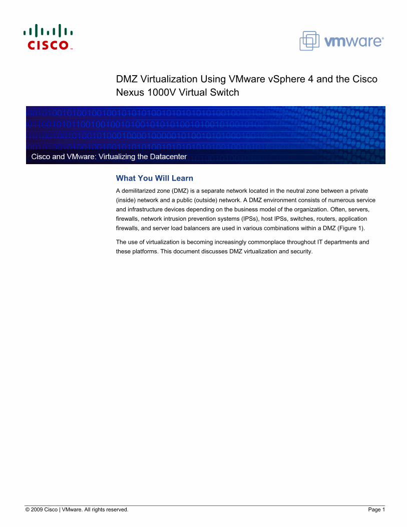
DMZ Virtualization Using VMware vSphere 4 and the Cisco Nexus 1000V Virtual Switch
What You Will Learn A demilitarized zone (DMZ) is a separate network located in the neutral zone between a private
(inside) network and a public (outside) network. A DMZ environment consists of numerous service
and infrastructure devices depending on the business model of the organization. Often, servers,
firewalls, network intrusion prevention systems (IPSs), host IPSs, switches, routers, application
firewalls, and server load balancers are used in various combinations within a DMZ (Figure 1).
The use of virtualization is becoming increasingly commonplace throughout IT departments and
these platforms. This document discusses DMZ virtualization and security.
© 2009 Cisco | VMware. All rights reserved. Page 2
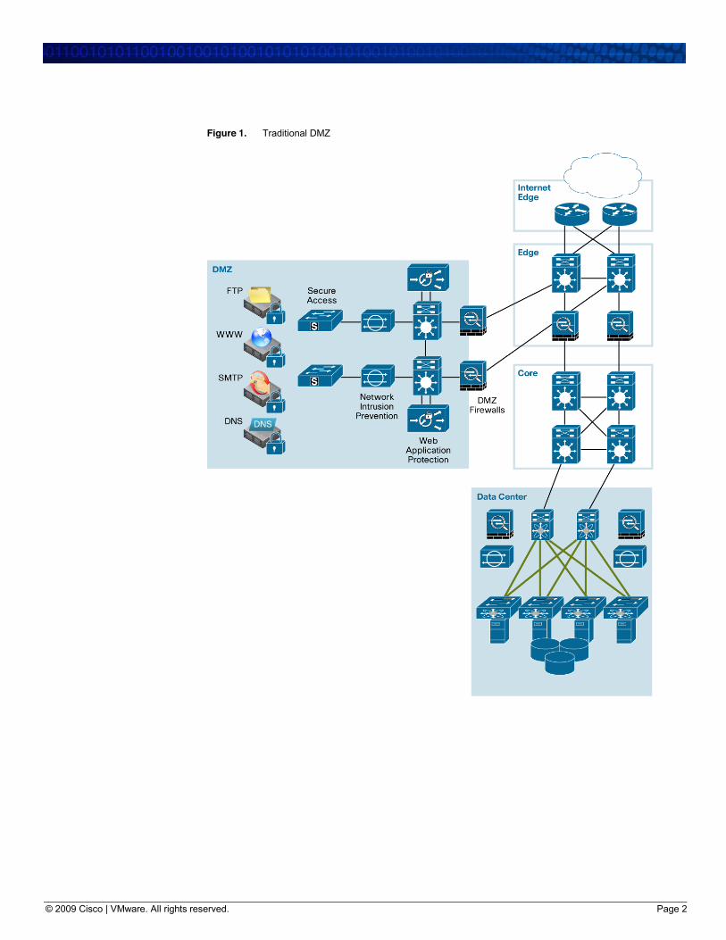
Figure 1. Traditional DMZ
© 2009 Cisco | VMware. All rights reserved. Page 3
DMZ Virtualization The virtualized DMZ takes advantage of virtualization technologies to reduce the DMZ footprint,
thereby freeing valuable rack space, which in turn reduces power consumption and overall operating
costs. Server and infrastructure virtualization are two main components of the virtualized DMZ.
Through the use of server virtualization, applications residing in the DMZ are moved to virtual
machines, many of which can reside on the same physical server (Figure 2).
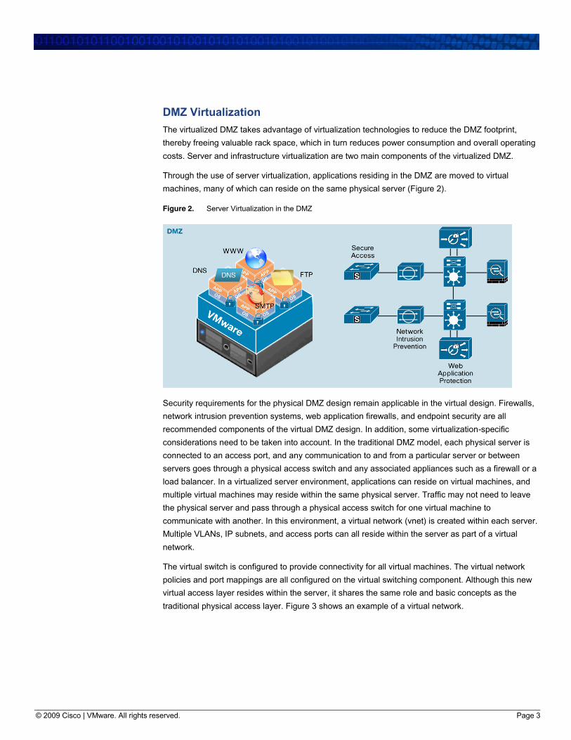
Figure 2. Server Virtualization in the DMZ
Security requirements for the physical DMZ design remain applicable in the virtual design. Firewalls,
network intrusion prevention systems, web application firewalls, and endpoint security are all
recommended components of the virtual DMZ design. In addition, some virtualization-specific
considerations need to be taken into account. In the traditional DMZ model, each physical server is
connected to an access port, and any communication to and from a particular server or between
servers goes through a physical access switch and any associated appliances such as a firewall or a
load balancer. In a virtualized server environment, applications can reside on virtual machines, and
multiple virtual machines may reside within the same physical server. Traffic may not need to leave
the physical server and pass through a physical access switch for one virtual machine to
communicate with another. In this environment, a virtual network (vnet) is created within each server.
Multiple VLANs, IP subnets, and access ports can all reside within the server as part of a virtual
network.
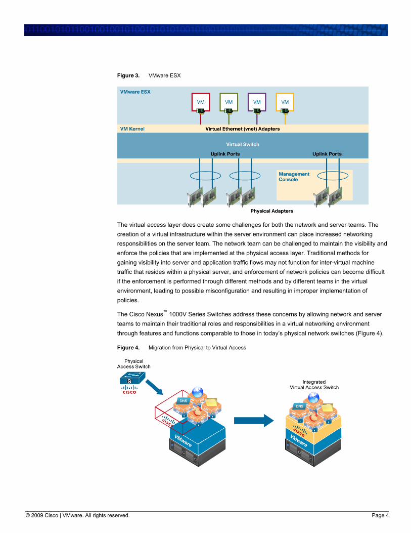
The virtual switch is configured to provide connectivity for all virtual machines. The virtual network
policies and port mappings are all configured on the virtual switching component. Although this new
virtual access layer resides within the server, it shares the same role and basic concepts as the
traditional physical access layer. Figure 3 shows an example of a virtual network.
© 2009 Cisco | VMware. All rights reserved. Page 4
Figure 3. VMware ESX
The virtual access layer does create some challenges for both the network and server teams. The
creation of a virtual infrastructure within the server environment can place increased networking
responsibilities on the server team. The network team can be challenged to maintain the visibility and
enforce the policies that are implemented at the physical access layer. Traditional methods for
gaining visibility into server and application traffic flows may not function for inter-virtual machine
traffic that resides within a physical server, and enforcement of network policies can become difficult
if the enforcement is performed through different methods and by different teams in the virtual
environment, leading to possible misconfiguration and resulting in improper implementation of
policies.
The Cisco Nexus™ 1000V Series Switches address these concerns by allowing network and server
teams to maintain their traditional roles and responsibilities in a virtual networking environment
through features and functions comparable to those in today’s physical network switches (Figure 4).
Figure 4. Migration from Physical to Virtual Access
© 2009 Cisco | VMware. All rights reserved. Page 5
Cisco Nexus 1000V Series Virtual Switch The Cisco Nexus 1000V Series is a virtual network distributed switch (vDS) platform supported by
the VMware vSphere product. The Cisco Nexus 1000V Series consists of two components: the
virtual supervisor module (VSM) and the virtual Ethernet module (VEM). The VSM acts in a similar
fashion to a traditional Cisco® supervisor module. The networking and policy configurations are
performed on the VSM and applied to the ports on each VEM. The VEM is similar to a traditional
Cisco line card and provides the ports for host (virtual machine) connectivity. The VEM resides in the
physical server as the virtual switching component.
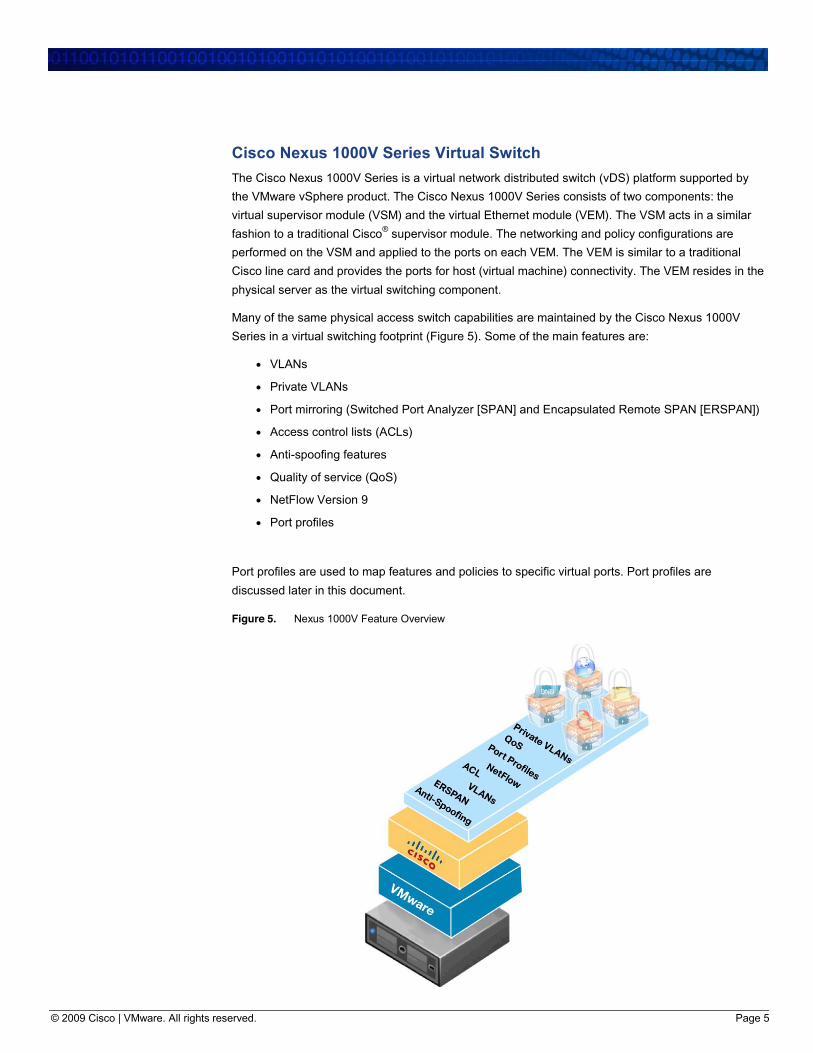
Many of the same physical access switch capabilities are maintained by the Cisco Nexus 1000V
Series in a virtual switching footprint (Figure 5). Some of the main features are:
● VLANs
● Private VLANs
● Port mirroring (Switched Port Analyzer [SPAN] and Encapsulated Remote SPAN [ERSPAN])
● Access control lists (ACLs)
● Anti-spoofing features
● Quality of service (QoS)
● NetFlow Version 9
● Port profiles
Port profiles are used to map features and policies to specific virtual ports. Port profiles are
discussed later in this document.
Figure 5. Nexus 1000V Feature Overview
© 2009 Cisco | VMware. All rights reserved. Page 6
DMZ Virtualization with Cisco Nexus 1000V Series In the virtualized DMZ, the Cisco Nexus 1000V Series provides virtual access switching in a VMware
vSphere server environment. The virtual switch provides connectivity between the virtual machine
virtual network interface cards (NICs) and the physical NICs of the server. The physical NICs are
configured as uplink ports on the Cisco Nexus 1000V Series.
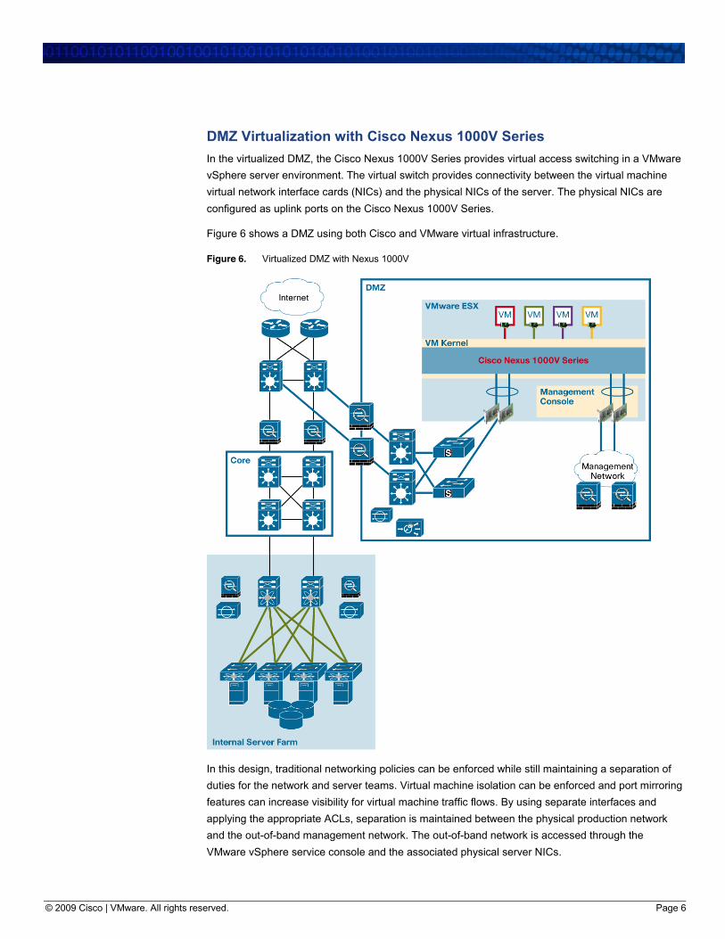
Figure 6 shows a DMZ using both Cisco and VMware virtual infrastructure.
Figure 6. Virtualized DMZ with Nexus 1000V
In this design, traditional networking policies can be enforced while still maintaining a separation of
duties for the network and server teams. Virtual machine isolation can be enforced and port mirroring
features can increase visibility for virtual machine traffic flows. By using separate interfaces and
applying the appropriate ACLs, separation is maintained between the physical production network
and the out-of-band management network. The out-of-band network is accessed through the
VMware vSphere service console and the associated physical server NICs.
© 2009 Cisco | VMware. All rights reserved. Page 7
The following sections describe some of the Cisco Nexus 1000V Series features and how they can
be applied to the virtual infrastructure.
Mapping Roles and Responsibilities
Port Profiles and Port Groups The use of server virtualization has increased some of the responsibilities of the server
administration team. Traditionally the network and security teams are responsible for configuring all
network components for server connectivity; server administrators simply connect the server to the
preconfigured access port. In a virtual environment, some of the network functions now reside in the
virtual server platform. VLAN assignment, port mapping, and inter-virtual machine communication
can all be configured within the virtual server. VMware vCenter Server enables server administrators
to configure the virtual networking components.
This approach often brings some contention as to who is responsible for the networking and security
policies and this virtualized layer. Miscommunication or a simple configuration mistake can
subsequently lead to assignment of the wrong VLAN and policy to a virtual machine. In most cases,
the server teams have no desire to become network engineers and would rather save time and work
by simply applying a predefined network policy to their servers.
The Cisco Nexus 1000V Series offers a significant administration benefit. When a network policy is
defined on the Cisco Nexus 1000V Series, it is updated in VMware vCenter and displayed as an
option on the Port Group drop-down list. This updating is achieved through the use of an API for
communication between the virtual supervisor module and the VMware vCenter Server. The network
teams can configured a predefined server policy and make it available for selection (through VMware
vCenter) to the server administrators in the same manner as is used to apply policies today through
port groups.
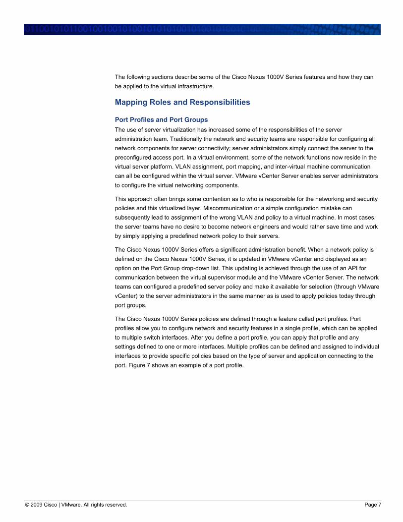
The Cisco Nexus 1000V Series policies are defined through a feature called port profiles. Port
profiles allow you to configure network and security features in a single profile, which can be applied
to multiple switch interfaces. After you define a port profile, you can apply that profile and any
settings defined to one or more interfaces. Multiple profiles can be defined and assigned to individual
interfaces to provide specific policies based on the type of server and application connecting to the
port. Figure 7 shows an example of a port profile.
© 2009 Cisco | VMware. All rights reserved. Page 8
Figure 7. Port Profile Configuration Example
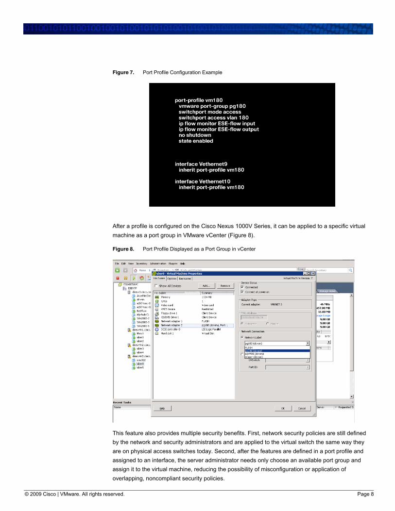
After a profile is configured on the Cisco Nexus 1000V Series, it can be applied to a specific virtual
machine as a port group in VMware vCenter (Figure 8).
Figure 8. Port Profile Displayed as a Port Group in vCenter
This feature also provides multiple security benefits. First, network security policies are still defined
by the network and security administrators and are applied to the virtual switch the same way they
are on physical access switches today. Second, after the features are defined in a port profile and
assigned to an interface, the server administrator needs only choose an available port group and
assign it to the virtual machine, reducing the possibility of misconfiguration or application of
overlapping, noncompliant security policies.
© 2009 Cisco | VMware. All rights reserved. Page 9
Maintaining Isolation and Protection
VLANs, Private VLANs, ACLs, Anti-Spoofing The methods used today to provide isolation and protection in the server farm are available to apply
in the virtual infrastructure as well. The use of VLANs, private VLANs, ACLs, and the application of
anti-spoofing features to protect against man-in-the-middle attacks and maintain separation is
supported on the virtual infrastructure.
VLANs with applied ACLs can be used to control traffic to different virtual machines and applications.
VLANs provide a reliable and proven method for segmenting traffic flows in the network. A study
detailing VLAN security was conducted several years ago by @stake and is available at
http://www.cisco.com/warp/public/cc/pd/si/casi/ca6000/tech/stake_wp.pdf.
VLAN security best practices and recommendations are still valid and should be used in the virtual
environment. Dozens of documents describing VLAN best practices are available. A white paper
highlighting VLAN security considerations and recommendations is available at
http://www.cisco.com/warp/public/cc/pd/si/casi/ca6000/prodlit/vlnwp_wp.htm.
Just as in a physical environment, servers residing in the same VLAN can still directly access one
another, which can pose a problem if one of the servers is compromised. Attacks could be launched
from the compromised server to other servers in the VLAN or broadcast domain. These could be
application-specific attacks, man-in-the-middle attacks, or network-based attacks targeted at
compromising systems and capturing data.
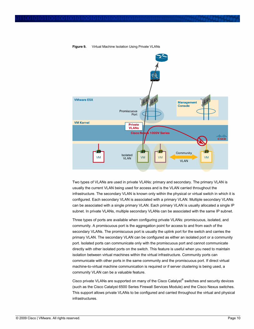
Private VLANs provide a means for isolation of machines within the same VLAN (see Figure 9).
Originally developed for service providers as a means of scaling IP addresses in a hosting
environment, this feature is very useful in the virtual switching environment.
© 2009 Cisco | VMware. All rights reserved. Page 10
Figure 9. Virtual Machine Isolation Using Private VLANs
Two types of VLANs are used in private VLANs: primary and secondary. The primary VLAN is
usually the current VLAN being used for access and is the VLAN carried throughout the
infrastructure. The secondary VLAN is known only within the physical or virtual switch in which it is
configured. Each secondary VLAN is associated with a primary VLAN. Multiple secondary VLANs
can be associated with a single primary VLAN. Each primary VLAN is usually allocated a single IP
subnet. In private VLANs, multiple secondary VLANs can be associated with the same IP subnet.
Three types of ports are available when configuring private VLANs: promiscuous, isolated, and
community. A promiscuous port is the aggregation point for access to and from each of the
secondary VLANs. The promiscuous port is usually the uplink port for the switch and carries the
primary VLAN. The secondary VLAN can be configured as either an isolated port or a community
port. Isolated ports can communicate only with the promiscuous port and cannot communicate
directly with other isolated ports on the switch. This feature is useful when you need to maintain
isolation between virtual machines within the virtual infrastructure. Community ports can
communicate with other ports in the same community and the promiscuous port. If direct virtual
machine-to-virtual machine communication is required or if server clustering is being used, a
community VLAN can be a valuable feature.
Cisco private VLANs are supported on many of the Cisco Catalyst® switches and security devices
(such as the Cisco Catalyst 6500 Series Firewall Services Module) and the Cisco Nexus switches.
This support allows private VLANs to be configured and carried throughout the virtual and physical
infrastructures.
© 2009 Cisco | VMware. All rights reserved. Page 11
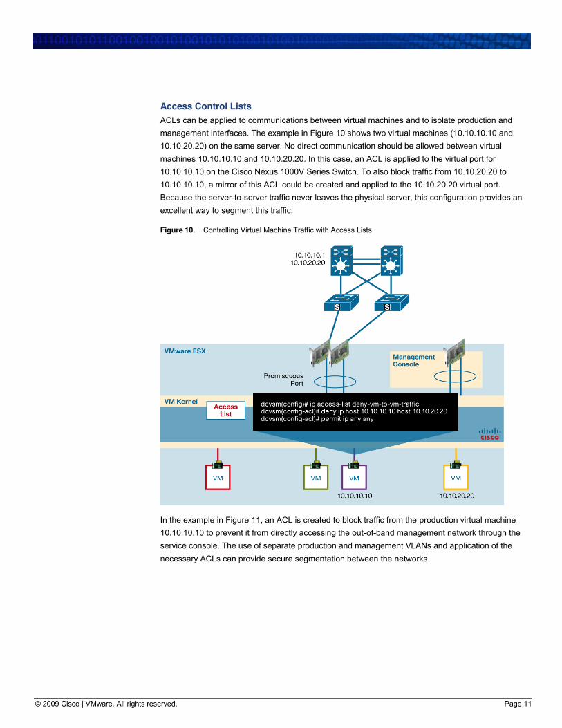
Access Control Lists ACLs can be applied to communications between virtual machines and to isolate production and
management interfaces. The example in Figure 10 shows two virtual machines (10.10.10.10 and
10.10.20.20) on the same server. No direct communication should be allowed between virtual
machines 10.10.10.10 and 10.10.20.20. In this case, an ACL is applied to the virtual port for
10.10.10.10 on the Cisco Nexus 1000V Series Switch. To also block traffic from 10.10.20.20 to
10.10.10.10, a mirror of this ACL could be created and applied to the 10.10.20.20 virtual port.
Because the server-to-server traffic never leaves the physical server, this configuration provides an
excellent way to segment this traffic.
Figure 10. Controlling Virtual Machine Traffic with Access Lists
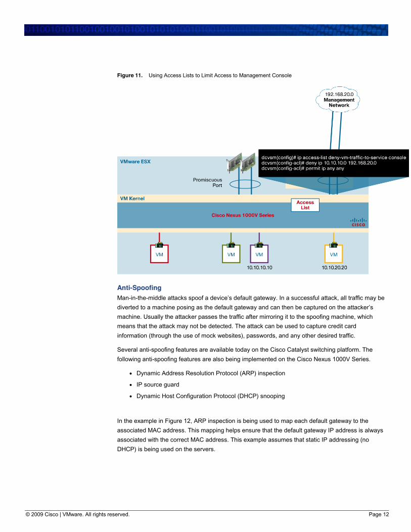
In the example in Figure 11, an ACL is created to block traffic from the production virtual machine
10.10.10.10 to prevent it from directly accessing the out-of-band management network through the
service console. The use of separate production and management VLANs and application of the
necessary ACLs can provide secure segmentation between the networks.
© 2009 Cisco | VMware. All rights reserved. Page 12
Figure 11. Using Access Lists to Limit Access to Management Console
Anti-Spoofing Man-in-the-middle attacks spoof a device’s default gateway. In a successful attack, all traffic may be diverted to a machine posing as the default gateway and can then be captured on the attacker’s machine. Usually the attacker passes the traffic after mirroring it to the spoofing machine, which
means that the attack may not be detected. The attack can be used to capture credit card
information (through the use of mock websites), passwords, and any other desired traffic.
Several anti-spoofing features are available today on the Cisco Catalyst switching platform. The
following anti-spoofing features are also being implemented on the Cisco Nexus 1000V Series.
● Dynamic Address Resolution Protocol (ARP) inspection
● IP source guard
● Dynamic Host Configuration Protocol (DHCP) snooping
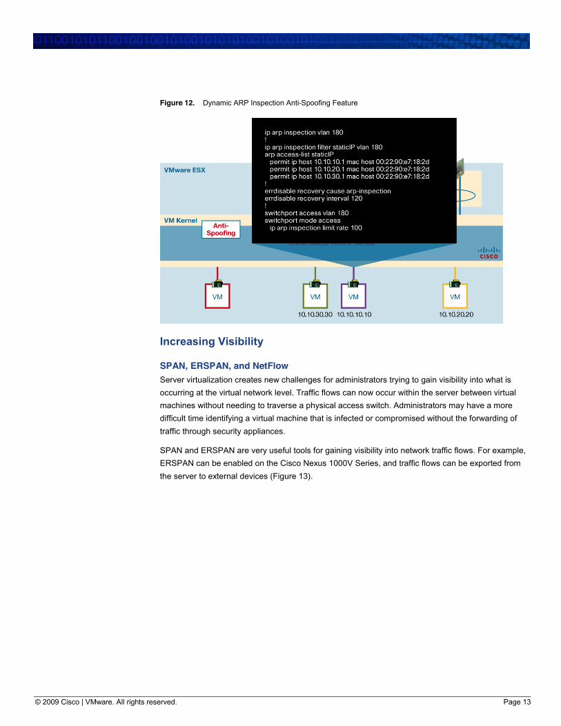
In the example in Figure 12, ARP inspection is being used to map each default gateway to the
associated MAC address. This mapping helps ensure that the default gateway IP address is always
associated with the correct MAC address. This example assumes that static IP addressing (no
DHCP) is being used on the servers.
© 2009 Cisco | VMware. All rights reserved. Page 13
Figure 12. Dynamic ARP Inspection Anti-Spoofing Feature
Increasing Visibility
SPAN, ERSPAN, and NetFlow Server virtualization creates new challenges for administrators trying to gain visibility into what is
occurring at the virtual network level. Traffic flows can now occur within the server between virtual
machines without needing to traverse a physical access switch. Administrators may have a more
difficult time identifying a virtual machine that is infected or compromised without the forwarding of
traffic through security appliances.
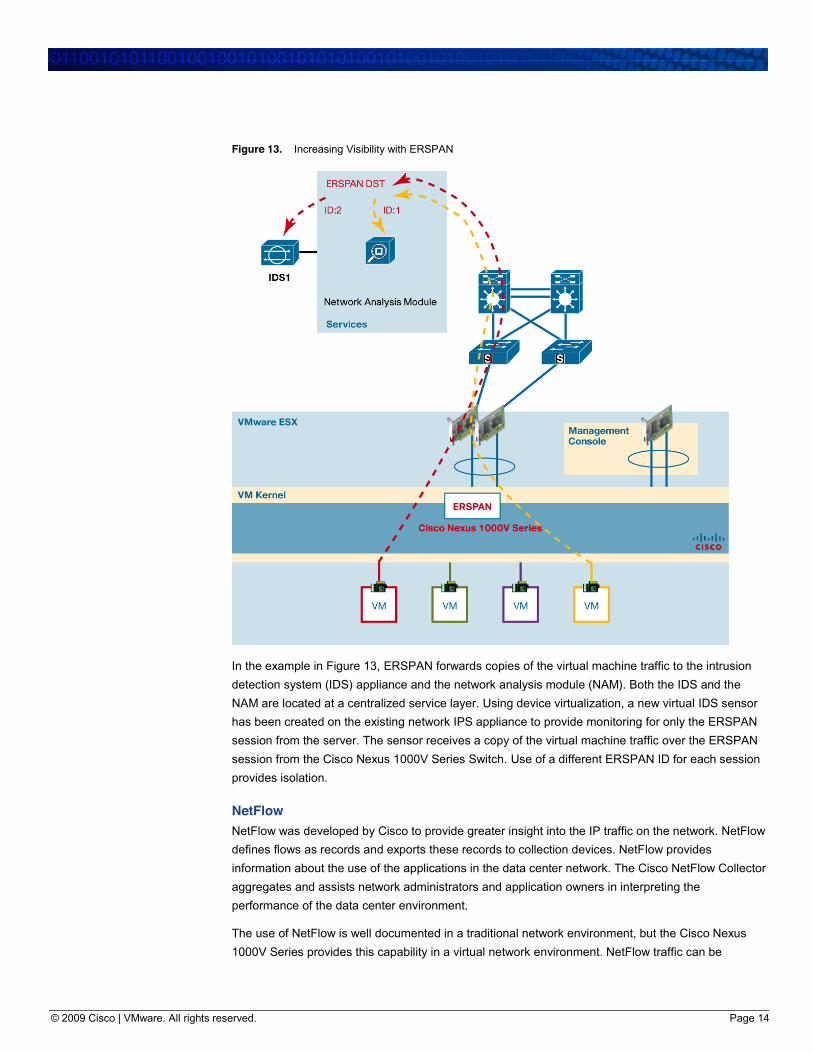
SPAN and ERSPAN are very useful tools for gaining visibility into network traffic flows. For example,
ERSPAN can be enabled on the Cisco Nexus 1000V Series, and traffic flows can be exported from
the server to external devices (Figure 13).
© 2009 Cisco | VMware. All rights reserved. Page 14
Figure 13. Increasing Visibility with ERSPAN
In the example in Figure 13, ERSPAN forwards copies of the virtual machine traffic to the intrusion
detection system (IDS) appliance and the network analysis module (NAM). Both the IDS and the
NAM are located at a centralized service layer. Using device virtualization, a new virtual IDS sensor
has been created on the existing network IPS appliance to provide monitoring for only the ERSPAN
session from the server. The sensor receives a copy of the virtual machine traffic over the ERSPAN
session from the Cisco Nexus 1000V Series Switch. Use of a different ERSPAN ID for each session
provides isolation.
NetFlow NetFlow was developed by Cisco to provide greater insight into the IP traffic on the network. NetFlow
defines flows as records and exports these records to collection devices. NetFlow provides
information about the use of the applications in the data center network. The Cisco NetFlow Collector
aggregates and assists network administrators and application owners in interpreting the
performance of the data center environment.
The use of NetFlow is well documented in a traditional network environment, but the Cisco Nexus
1000V Series provides this capability in a virtual network environment. NetFlow traffic can be
© 2009 Cisco | VMware. All rights reserved. Page 15
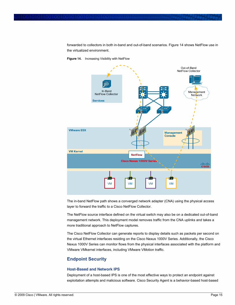
forwarded to collectors in both in-band and out-of-band scenarios. Figure 14 shows NetFlow use in
the virtualized environment.
Figure 14. Increasing Visibility with NetFlow
The in-band NetFlow path shows a converged network adapter (CNA) using the physical access
layer to forward the traffic to a Cisco NetFlow Collector.
The NetFlow source interface defined on the virtual switch may also be on a dedicated out-of-band
management network. This deployment model removes traffic from the CNA uplinks and takes a
more traditional approach to NetFlow captures.
The Cisco NetFlow Collector can generate reports to display details such as packets per second on
the virtual Ethernet interfaces residing on the Cisco Nexus 1000V Series. Additionally, the Cisco
Nexus 1000V Series can monitor flows from the physical interfaces associated with the platform and
VMware VMkernel interfaces, including VMware VMotion traffic.
Endpoint Security
Host-Based and Network IPS Deployment of a host-based IPS is one of the most effective ways to protect an endpoint against
exploitation attempts and malicious software. Cisco Security Agent is a behavior-based host-based
© 2009 Cisco | VMware. All rights reserved. Page 16
IPS solution. Cisco Security Agent can mitigate known attacks is also effective at thwarting zero-day
attacks. By looking at the behavioral aspects of an attack, Cisco Security Agent can detect and stop
new attacks without first needing installation of a signature before it can identify the particular attack
(Figure 15).
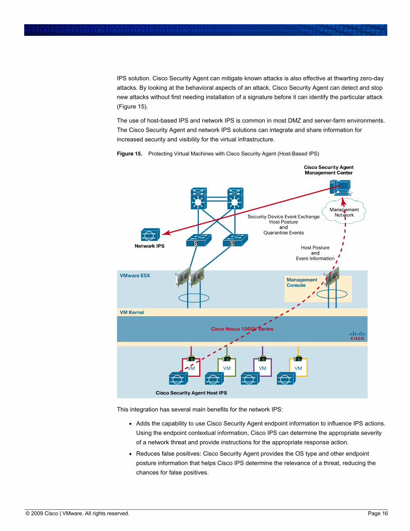
The use of host-based IPS and network IPS is common in most DMZ and server-farm environments.
The Cisco Security Agent and network IPS solutions can integrate and share information for
increased security and visibility for the virtual infrastructure.
Figure 15. Protecting Virtual Machines with Cisco Security Agent (Host-Based IPS)
This integration has several main benefits for the network IPS:
● Adds the capability to use Cisco Security Agent endpoint information to influence IPS actions.
Using the endpoint contextual information, Cisco IPS can determine the appropriate severity
of a network threat and provide instructions for the appropriate response action.
● Reduces false positives: Cisco Security Agent provides the OS type and other endpoint
posture information that helps Cisco IPS determine the relevance of a threat, reducing the
chances for false positives.
© 2009 Cisco | VMware. All rights reserved. Page 17
● Enhances attack mitigation: Cisco IPS can use the watch list maintained by Cisco Security
Agent. The watch list helps Cisco IPS monitor systems identified by Cisco Security Agent as
suspicious or malicious, and helps highlight any events associated with these systems.
● Enables dynamic host quarantine: Cisco IPS dynamically blocks hosts that have been
identified by Cisco Security Agent as malicious. This feature extends the quarantine
capabilities from Cisco Security Agent to the IPS.
Consolidated DMZ Architecture Traditionally, DMZ designs make use of a separate infrastructure dedicated to maintaining isolation
of DMZ services from the internal enterprise network. This separation requires the use of dedicated
servers to host DMZ-based applications. This model is very secure, but it does not make the best
use of server resources. Prior to server virtualization, this was the only model available that could
meet most security requirements.
Server virtualization is coming into the mainstream and bringing with it new design options to
networks and server farms. Through integration of network-based security capabilities in the
virtualized infrastructure, existing security policies can be maintained in many of these new designs,
allowing organizations to explore the consolidation of server resources, including in DMZ
environments.
Consolidation of a mix of internal and DMZ virtual machines on the same physical server does
support a better use of resources, but a strict security policy must be followed to maintain proper
isolation of the two environments. In a traditional DMZ environment, different levels of security
policies are assigned to the DMZ-based hosts than to those assigned to the internal enterprise hosts.
Maintaining these security policies for the consolidated virtual architectures is just as important, or
more so. Isolation and segmentation of DMZ and internal hosts must be maintained, appropriate
access rights must be enforced for DMZ and internal resources, and logging features to maintain
visibility should be in place.
In addition, isolation must be maintained between non-production (management) and production
interfaces. The physical connections must be secured and assigned to the correct management and
production ports of the network infrastructure. This isolation must be maintained within the virtual
infrastructure as well. Virtual ports must be mapped to the correct physical ports and assigned the
correct policies. Maintenance of detailed documentation about these environments is essential to
enable network and server administrators to have a clear understanding of the infrastructure and to
decrease the chance of misconfiguration.
Ways to accomplish these objectives include use of:
● Physical network segmentation with firewalls to maintain stateful traffic inspection of
production and non-production traffic
● Port profiles to maintain separation of duties and enforce policy
● Authentication, authorization, and accounting (AAA) to define access rights and maintain
accurate logs
● VLAN and private VLANs for isolation of virtual machines and applications
© 2009 Cisco | VMware. All rights reserved. Page 18
● ACLs to limit access between DMZ virtual machines, production network, and management
networks
● Increased operational visibility in the virtual DMZ environment with ERSPAN and NetFlow
● Rate limiting to reduce the effect of malicious traffic from a compromised machine
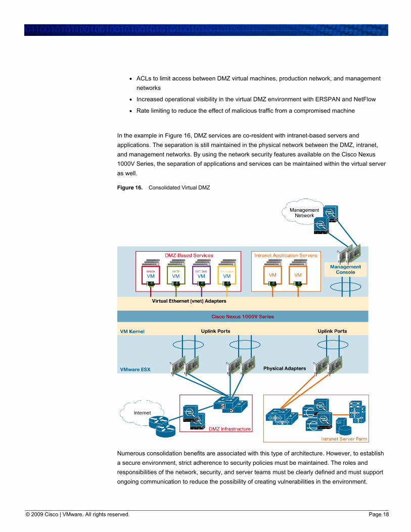
In the example in Figure 16, DMZ services are co-resident with intranet-based servers and
applications. The separation is still maintained in the physical network between the DMZ, intranet,
and management networks. By using the network security features available on the Cisco Nexus
1000V Series, the separation of applications and services can be maintained within the virtual server
as well.
Figure 16. Consolidated Virtual DMZ
Numerous consolidation benefits are associated with this type of architecture. However, to establish
a secure environment, strict adherence to security policies must be maintained. The roles and
responsibilities of the network, security, and server teams must be clearly defined and must support
ongoing communication to reduce the possibility of creating vulnerabilities in the environment.
© 2009 Cisco | VMware. All rights reserved. Page 19
General Recommendations for Achieving a Secure Virtualized DMZ ● Maintain security as you would in a physical non-virtualized environment.
● Secure the hypervisor using VMware recommendations.
● Be aware of applications with different security affinities on the same server.
● Limit connectivity to both VMware VMkernel and VMotion segments.
● Use available tools to control virtual machine-to-virtual machine traffic flows.
● Use monitoring tools to increase the visibility of virtual machine activity and traffic flows.
● Maintain detailed documentation for virtual and physical network connections.
● Have a clear separation of roles and responsibilities.
● Enforce clearly defined change management controls.
● Perform ongoing auditing and monitoring.
Conclusion Virtualization can reduce data center power consumption, required rack space, and the amount of
idle and underused server resources. Virtualization and its accompanying benefits can be used in
the DMZ just as they are in other areas of the network. By following server deployment and network
design best practices a secure virtualized DMZ environment can be implemented. The Cisco Nexus
1000V Series bridges the gap between the physical and virtual infrastructure and allows traditional
Cisco networking and security features to be enabled for the virtual infrastructure while maintaining
the respective roles and responsibilities of the network, security, and server teams.
For More Information
More Information: VMware ● VMware Security Technology Center: http://www.vmware.com/go/security/
● Virtual Networking Technology Center: http://www.vmware.com/go/networking
● VMware Infrastructure 3 security hardening:
http://www.vmware.com/resources/techresources/726
● Managing VMware VirtualCenter roles and permissions:
http://www.vmware.com/resources/techresources/826
● DMZ virtualization with VMware infrastructure:
http://www.vmware.com/resources/techresources/1052
More Information: Cisco ● Cisco Security homepage: http://www.cisco.com/en/US/products/hw/vpndevc/
● Network security baseline:
https://www.cisco.com/en/US/docs/solutions/Enterprise/Security/Baseline_Security/sec_chap
2.html
● Cisco SAFE recommendations: http://www.cisco.com/go/safe
● Cisco data center design:
http://www.cisco.com/en/US/netsol/ns743/networking_solutions_program_home.html
© 2009 Cisco | VMware. All rights reserved. Page 20
Version: 1 Date: 2009.06.17
Cisco Systems, Inc. 170 West Tasman Drive San Jose, CA 95134-1706 USA www.cisco.com Tel: 408 526-4000 800 553-NETS (6387) Fax: 408 527-0883
VMware, Inc 3401 Hillview Ave Palo Alto, CA 94304 USA www.vmware.com Tel: 1-877-486-9273 or 650-427-5000 Fax: 650-427-5001
Copyright © 2009. VMware, Inc. All rights reserved. Protected by one or more U.S. Patent Nos. 6,397,242, 6,496,847, 6,704,925, 6,711,672, 6,725,289, 6,735,601, 6,785,886, 6,789,156, 6,795,966, 6,880,022, 6,944,699, 6,961,806, 6,961,941, 7,069,413, 7,082,598, 7,089,377, 7,111,086, 7,111,145, 7,117,481, 7,149, 843, 7,155,558, 7,222,221, 7,260,815, 7,260,820, 7,269,683, 7,275,136, 7,277,998,7,277,999, 7,278,030, 7,281,102, 7,290,253, 7,356,679 and patents pending.
Cisco, the Cisco logo, and Cisco Systems are registered trademarks or trademarks of Cisco Systems, Inc. and/or its affiliates in the United States and certain other countries. All other trademarks mentioned in this document or Website are the property of their respective owners. The use of the word partner does not imply a partnership relationship between Cisco and any other company.
(0812R) XXX-XXXXXX-00 06/09