Embed Size (px)
Citation preview
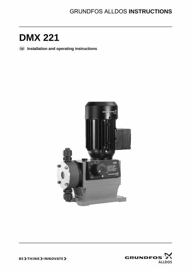
DMX 221
GRUNDFOS ALLDOS INSTRUCTIONS
Installation and operating instructions
Declaration of ConformityWe Grundfos Alldos declare under our sole responsibility that the products DMX 221, to which this declaration relates, are in conformity with the Council Directives on the approximation of the laws of the EC Member States relating to— Machinery (98/37/EC).
Standard used: EN ISO 12100.— Electromagnetic compatibility (89/336/EEC).
Standards used: EN 61000-3-2: 1995, + A1 + A2, EN 61000-3-3: 1995 and EN 61326: 1997, + A1 + A2, Class B.
— Electrical equipment designed for use within certain voltage limits (73/23/EEC) [95].Standard used: EN 61010-1: 2002.
Pfinztal, 1st June 2007
W. SchwaldManaging Director
2
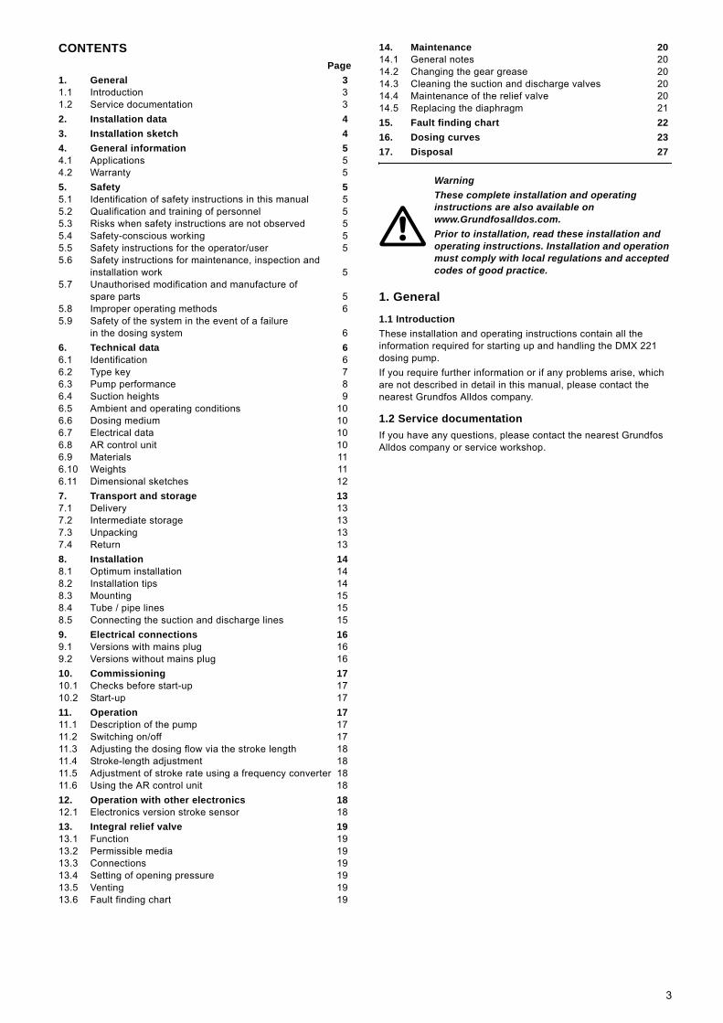
CONTENTSPage
1. General 31.1 Introduction 31.2 Service documentation 32. Installation data 43. Installation sketch 44. General information 54.1 Applications 54.2 Warranty 55. Safety 55.1 Identification of safety instructions in this manual 55.2 Qualification and training of personnel 55.3 Risks when safety instructions are not observed 55.4 Safety-conscious working 55.5 Safety instructions for the operator/user 55.6 Safety instructions for maintenance, inspection and
installation work 55.7 Unauthorised modification and manufacture of
spare parts 55.8 Improper operating methods 65.9 Safety of the system in the event of a failure
in the dosing system 66. Technical data 66.1 Identification 66.2 Type key 76.3 Pump performance 86.4 Suction heights 96.5 Ambient and operating conditions 106.6 Dosing medium 106.7 Electrical data 106.8 AR control unit 106.9 Materials 116.10 Weights 116.11 Dimensional sketches 127. Transport and storage 137.1 Delivery 137.2 Intermediate storage 137.3 Unpacking 137.4 Return 138. Installation 148.1 Optimum installation 148.2 Installation tips 148.3 Mounting 158.4 Tube / pipe lines 158.5 Connecting the suction and discharge lines 159. Electrical connections 169.1 Versions with mains plug 169.2 Versions without mains plug 1610. Commissioning 1710.1 Checks before start-up 1710.2 Start-up 1711. Operation 1711.1 Description of the pump 1711.2 Switching on/off 1711.3 Adjusting the dosing flow via the stroke length 1811.4 Stroke-length adjustment 1811.5 Adjustment of stroke rate using a frequency converter 1811.6 Using the AR control unit 1812. Operation with other electronics 1812.1 Electronics version stroke sensor 1813. Integral relief valve 1913.1 Function 1913.2 Permissible media 1913.3 Connections 1913.4 Setting of opening pressure 1913.5 Venting 1913.6 Fault finding chart 19
14. Maintenance 2014.1 General notes 2014.2 Changing the gear grease 2014.3 Cleaning the suction and discharge valves 2014.4 Maintenance of the relief valve 2014.5 Replacing the diaphragm 2115. Fault finding chart 2216. Dosing curves 2317. Disposal 27
1. General
1.1 IntroductionThese installation and operating instructions contain all the information required for starting up and handling the DMX 221 dosing pump.If you require further information or if any problems arise, which are not described in detail in this manual, please contact the nearest Grundfos Alldos company.
1.2 Service documentationIf you have any questions, please contact the nearest Grundfos Alldos company or service workshop.
WarningThese complete installation and operating instructions are also available on www.Grundfosalldos.com.Prior to installation, read these installation and operating instructions. Installation and operation must comply with local regulations and accepted codes of good practice.
3
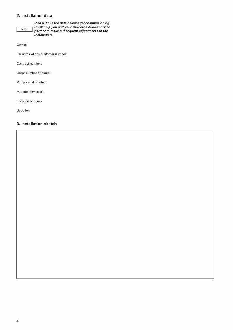
2. Installation data
Owner:
Grundfos Alldos customer number:
Contract number:
Order number of pump:
Pump serial number:
Put into service on:
Location of pump:
Used for:
3. Installation sketch
Note
Please fill in the data below after commissioning. It will help you and your Grundfos Alldos service partner to make subsequent adjustments to the installation.
4
4. General information
4.1 ApplicationsThe DMX 221 pump is suitable for liquid, non-abrasive and non-inflammable media strictly in accordance with the instructions in this manual.The DMX 221 dosing pumps have not been approved according to the EC directive 94/9/EC, the so-called ATEX directive. The application of these pumps in potentially explosive environments according to ATEX directive is therefore not permitted.
4.2 WarrantyWarranty in accordance with our general terms of sale and delivery is only valid• if the pump is used in accordance with the information within
this manual.• if the pump is not dismantled or incorrectly handled.• if repairs are carried out by authorised and qualified
personnel.• if original spare parts are used for repairs.
5. SafetyThis manual contains general instructions that must be observed during installation, operation and maintenance of the pump. This manual must therefore be read by the installation engineer and the relevant qualified personnel/operators prior to installation and start-up, and must be available at the installation location of the pump at all times. It is not only the general safety instructions given in this "Safety" section that must be observed, but also all the specific safety instructions given in other sections.
5.1 Identification of safety instructions in this manualIf the safety instructions or other advice in this manual are not observed, it may result in personal injury or malfunction and damage to the pump. The safety instructions and other advice are identified by the following symbols:
Information provided directly on the pump, e.g. labelling of fluid connections, must be observed and must be maintained in a readable condition at all times.
5.2 Qualification and training of personnelThe personnel responsible for the operation, maintenance, inspection and installation must be appropriately qualified for these tasks. Areas of responsibility, levels of authority and the supervision of the personnel must be precisely defined by the operator.If the personnel do not have the necessary knowledge, the necessary training and instruction must be given. If necessary, training can be performed by the manufacturer/supplier at the request of the operator of the pump. It is the responsibility of the operator to make sure that the contents of this manual are understood by the personnel.
5.3 Risks when safety instructions are not observedNon-observance of the safety instructions may have dangerous consequences for the personnel, the environment and the pump. If the safety instructions are not observed, all rights to claims for damages may be lost.Non-observance of the safety instructions may lead to the following hazards:• failure of important functions of the pump/system• failure of specified methods for maintenance• harm to humans from exposure to electrical, mechanical and
chemical influences• damage to the environment from leakage of harmful
substances.
5.4 Safety-conscious workingThe safety instructions in this manual, applicable national health and safety regulations and any operator internal working, operating and safety regulations must be observed.
5.5 Safety instructions for the operator/userHazardous hot or cold parts on the pump must be protected to prevent accidental contact.Leakages of dangerous substances (e.g. hot, toxic) must be disposed of in a way that is not harmful to the personnel or the environment. Legal regulations must be observed.Damage caused by electrical energy must be prevented (for more details, see for example the regulations of the VDE and the local electricity supply company).
5.6 Safety instructions for maintenance, inspection and installation work
The operator must ensure that all maintenance, inspection and installation work is carried out by authorised and qualified personnel, who have been adequately trained by reading this manual.All work on the pump should only be carried out when the pump is stopped. The procedure described in this manual for stopping the pump must be observed.Pumps or pump units which are used for media that are harmful to health must be decontaminated.All safety and protective equipment must be immediately restarted or put into operation once work is complete.Observe the points described in the initial start-up section prior to subsequent start-up.
5.7 Unauthorised modification and manufacture of spare parts
Modification or changes to the pump are only permitted following agreement with the manufacturer. Original spare parts and accessories authorised by the manufacturer are safe to use. Using other parts can result in liability for any resulting consequences.
WarningOther applications or the operation of pumps in ambient and operating conditions, which are not approved, are considered improper and are not permitted. Grundfos Alldos accepts no liability for any damage resulting from incorrect use.
WarningIf these safety instructions are not observed, it may result in personal injury!
CautionIf these safety instructions are not observed, it may result in malfunction or damage to the equipment!
Note Notes or instructions that make the job easier and ensure safe operation.
WarningElectrical connections must only be carried out by qualified personnel!The pump housing must only be opened by personnel authorised by Grundfos Alldos!
5

5.8 Improper operating methodsThe operational safety of the supplied pump is only ensured if it is used in accordance with section 1. General. The specified limit values must under no circumstances be exceeded.
5.9 Safety of the system in the event of a failure in the dosing system
DMX 221 dosing pumps are designed according to the latest technologies and are carefully manufactured and tested. However, a failure may occur in the dosing system. Systems in which dosing pumps are installed must be designed in such a way that the safety of the entire system is still ensured following a failure of the dosing pump. Provide the relevant monitoring and control functions for this.
6. Technical data
6.1 Identification
Fig. 1 DMX pump nameplate
TM03
859
9 22
07
Pos. Description
1 Type designation2 Model3 Maximum capacity [l/h]4 Voltage [V]5 Frequency [Hz]6 Product number7 Country of origin8 Year and week code9 Marks of approval, CE mark, etc.
10 Maximum pressure [bar]11 Serial number
6
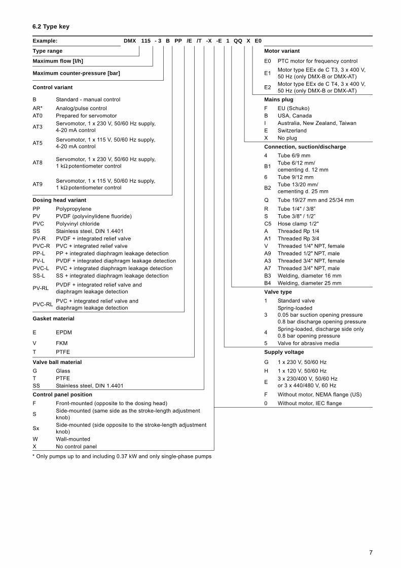
6.2 Type key
* Only pumps up to and including 0.37 kW and only single-phase pumps
Example: DMX 115 - 3 B PP /E /T -X -E 1 QQ X E0
Type range Motor variant
Maximum flow [l/h] E0 PTC motor for frequency control
Maximum counter-pressure [bar] E1 Motor type EEx de C T3, 3 x 400 V, 50 Hz (only DMX-B or DMX-AT)
Control variant E2 Motor type EEx de C T4, 3 x 400 V, 50 Hz (only DMX-B or DMX-AT)
B Standard - manual control Mains plugAR* Analog/pulse control F EU (Schuko)AT0 Prepared for servomotor B USA, Canada
AT3 Servomotor, 1 x 230 V, 50/60 Hz supply, 4-20 mA control
I Australia, New Zealand, TaiwanE Switzerland
AT5 Servomotor, 1 x 115 V, 50/60 Hz supply, 4-20 mA control
X No plugConnection, suction/discharge
AT8 Servomotor, 1 x 230 V, 50/60 Hz supply, 1 kΩ potentiometer control
4 Tube 6/9 mm
B1 Tube 6/12 mm/cementing d. 12 mm
AT9 Servomotor, 1 x 115 V, 50/60 Hz supply, 1 kΩ potentiometer control
6 Tube 9/12 mm
B2 Tube 13/20 mm/cementing d. 25 mm
Dosing head variant Q Tube 19/27 mm and 25/34 mmPP Polypropylene R Tube 1/4" / 3/8”PV PVDF (polyvinylidene fluoride) S Tube 3/8" / 1/2”PVC Polyvinyl chloride C5 Hose clamp 1/2"SS Stainless steel, DIN 1.4401 A Threaded Rp 1/4PV-R PVDF + integrated relief valve A1 Threaded Rp 3/4PVC-R PVC + integrated relief valve V Threaded 1/4" NPT, femalePP-L PP + integrated diaphragm leakage detection A9 Threaded 1/2" NPT, malePV-L PVDF + integrated diaphragm leakage detection A3 Threaded 3/4" NPT, femalePVC-L PVC + integrated diaphragm leakage detection A7 Threaded 3/4" NPT, maleSS-L SS + integrated diaphragm leakage detection B3 Welding, diameter 16 mm
PV-RL PVDF + integrated relief valve and diaphragm leakage detection
B4 Welding, diameter 25 mmValve type
PVC-RL PVC + integrated relief valve and diaphragm leakage detection
1 Standard valve
3Spring-loaded0.05 bar suction opening pressure 0.8 bar discharge opening pressure Gasket material
E EPDM 4 Spring-loaded, discharge side only0.8 bar opening pressure
V FKM 5 Valve for abrasive mediaT PTFE Supply voltage
Valve ball material G 1 x 230 V, 50/60 HzG Glass H 1 x 120 V, 50/60 HzT PTFE
E 3 x 230/400 V, 50/60 Hz or 3 x 440/480 V, 60 HzSS Stainless steel, DIN 1.4401
Control panel position F Without motor, NEMA flange (US)F Front-mounted (opposite to the dosing head) 0 Without motor, IEC flange
S Side-mounted (same side as the stroke-length adjustment knob)
Sx Side-mounted (side opposite to the stroke-length adjustment knob)
W Wall-mounted X No control panel
7
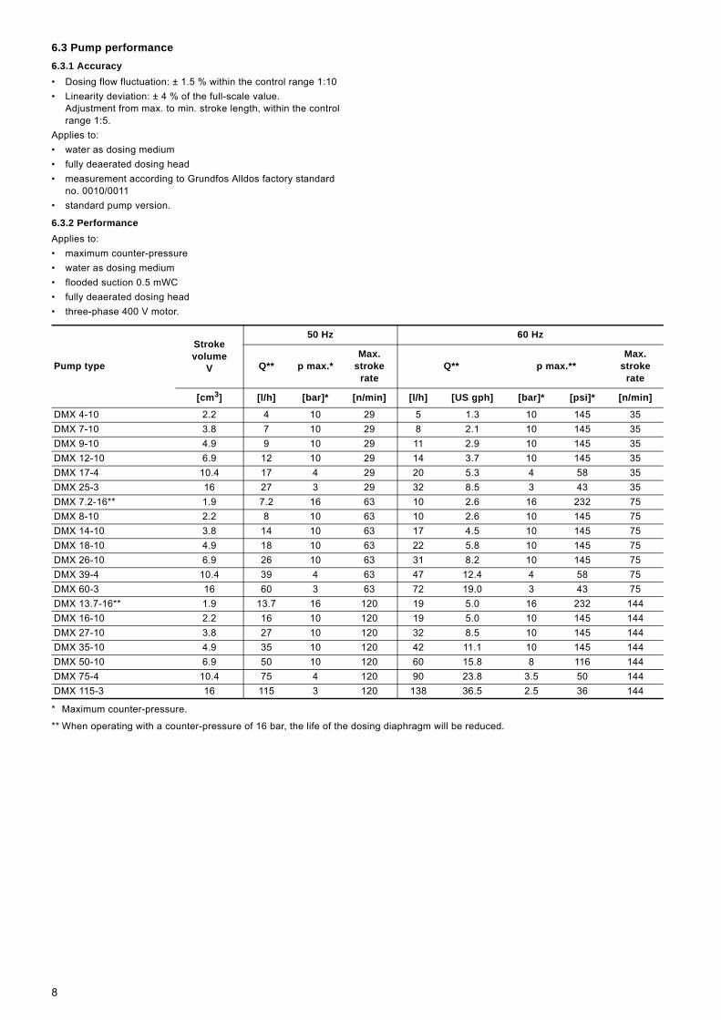
6.3 Pump performance6.3.1 Accuracy• Dosing flow fluctuation: ± 1.5 % within the control range 1:10• Linearity deviation: ± 4 % of the full-scale value.
Adjustment from max. to min. stroke length, within the control range 1:5.
Applies to:• water as dosing medium• fully deaerated dosing head• measurement according to Grundfos Alldos factory standard
no. 0010/0011• standard pump version.
6.3.2 PerformanceApplies to:• maximum counter-pressure• water as dosing medium• flooded suction 0.5 mWC• fully deaerated dosing head• three-phase 400 V motor.
* Maximum counter-pressure.
** When operating with a counter-pressure of 16 bar, the life of the dosing diaphragm will be reduced.
Pump type
Stroke volume
V
50 Hz 60 Hz
Q** p max.* Max.
stroke rate
Q** p max.**Max.
stroke rate
[cm3] [l/h] [bar]* [n/min] [l/h] [US gph] [bar]* [psi]* [n/min]
DMX 4-10 2.2 4 10 29 5 1.3 10 145 35DMX 7-10 3.8 7 10 29 8 2.1 10 145 35DMX 9-10 4.9 9 10 29 11 2.9 10 145 35DMX 12-10 6.9 12 10 29 14 3.7 10 145 35DMX 17-4 10.4 17 4 29 20 5.3 4 58 35DMX 25-3 16 27 3 29 32 8.5 3 43 35DMX 7.2-16** 1.9 7.2 16 63 10 2.6 16 232 75DMX 8-10 2.2 8 10 63 10 2.6 10 145 75DMX 14-10 3.8 14 10 63 17 4.5 10 145 75DMX 18-10 4.9 18 10 63 22 5.8 10 145 75DMX 26-10 6.9 26 10 63 31 8.2 10 145 75DMX 39-4 10.4 39 4 63 47 12.4 4 58 75DMX 60-3 16 60 3 63 72 19.0 3 43 75DMX 13.7-16** 1.9 13.7 16 120 19 5.0 16 232 144DMX 16-10 2.2 16 10 120 19 5.0 10 145 144DMX 27-10 3.8 27 10 120 32 8.5 10 145 144DMX 35-10 4.9 35 10 120 42 11.1 10 145 144DMX 50-10 6.9 50 10 120 60 15.8 8 116 144DMX 75-4 10.4 75 4 120 90 23.8 3.5 50 144DMX 115-3 16 115 3 120 138 36.5 2.5 36 144
8
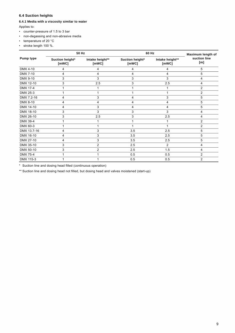
6.4 Suction heights6.4.1 Media with a viscosity similar to waterApplies to:• counter-pressure of 1.5 to 3 bar• non-degassing and non-abrasive media• temperature of 20 °C• stroke length 100 %.
* Suction line and dosing head filled (continuous operation)
** Suction line and dosing head not filled, but dosing head and valves moistened (start-up)
Pump type50 Hz 60 Hz Maximum length of
suction line [m]
Suction height*[mWC]
Intake height**[mWC]
Suction height*[mWC]
Intake height**[mWC]
DMX 4-10 4 4 4 4 5DMX 7-10 4 4 4 4 5DMX 9-10 3 3 3 3 4DMX 12-10 3 2.5 3 2.5 4DMX 17-4 1 1 1 1 2DMX 25-3 1 1 1 1 2DMX 7.2-16 4 3 4 3 5DMX 8-10 4 4 4 4 5DMX 14-10 4 3 4 4 5DMX 18-10 3 3 3 3 4DMX 26-10 3 2.5 3 2.5 4DMX 39-4 1 1 1 1 2DMX 60-3 1 1 1 1 2DMX 13.7-16 4 3 3.5 2.5 5DMX 16-10 4 3 3.5 2.5 5DMX 27-10 4 3 3.5 2.5 5DMX 35-10 3 2 2.5 2 4DMX 50-10 3 2 2.5 1.5 4DMX 75-4 1 1 0.5 0.5 2DMX 115-3 1 1 0.5 0.5 2
9
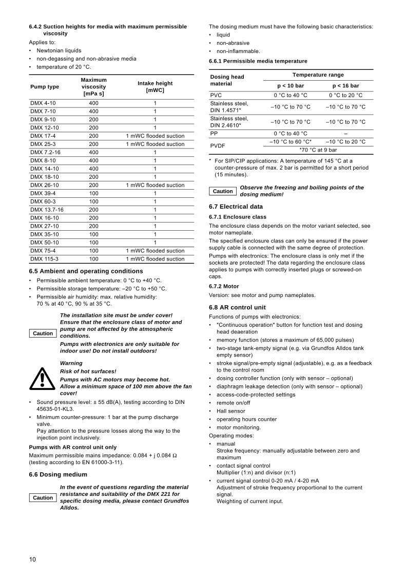
6.4.2 Suction heights for media with maximum permissible viscosity
Applies to:• Newtonian liquids• non-degassing and non-abrasive media• temperature of 20 °C.
6.5 Ambient and operating conditions• Permissible ambient temperature: 0 °C to +40 °C.• Permissible storage temperature: –20 °C to +50 °C.• Permissible air humidity: max. relative humidity:
70 % at 40 °C, 90 % at 35 °C.
• Sound pressure level: ± 55 dB(A), testing according to DIN 45635-01-KL3.
• Minimum counter-pressure: 1 bar at the pump discharge valve.Pay attention to the pressure losses along the way to the injection point inclusively.
Pumps with AR control unit onlyMaximum permissible mains impedance: 0.084 + j 0.084 Ω (testing according to EN 61000-3-11).
6.6 Dosing medium
The dosing medium must have the following basic characteristics:• liquid• non-abrasive• non-inflammable.
6.6.1 Permissible media temperature
* For SIP/CIP applications: A temperature of 145 °C at a counter-pressure of max. 2 bar is permitted for a short period (15 minutes).
6.7 Electrical data6.7.1 Enclosure classThe enclosure class depends on the motor variant selected, see motor nameplate.The specified enclosure class can only be ensured if the power supply cable is connected with the same degree of protection.Pumps with electronics: The enclosure class is only met if the sockets are protected! The data regarding the enclosure class applies to pumps with correctly inserted plugs or screwed-on caps.
6.7.2 MotorVersion: see motor and pump nameplates.
6.8 AR control unitFunctions of pumps with electronics:• "Continuous operation" button for function test and dosing
head deaeration• memory function (stores a maximum of 65,000 pulses) • two-stage tank-empty signal (e.g. via Grundfos Alldos tank
empty sensor)• stroke signal/pre-empty signal (adjustable), e.g. as a feedback
to the control room• dosing controller function (only with sensor – optional)• diaphragm leakage detection (only with sensor – optional)• access-code-protected settings• remote on/off• Hall sensor• operating hours counter• motor monitoring.Operating modes:• manual
Stroke frequency: manually adjustable between zero and maximum
• contact signal controlMultiplier (1:n) and divisor (n:1)
• current signal control 0-20 mA / 4-20 mAAdjustment of stroke frequency proportional to the current signal.Weighting of current input.
Pump typeMaximum viscosity [mPa s]
Intake height [mWC]
DMX 4-10 400 1DMX 7-10 400 1DMX 9-10 200 1DMX 12-10 200 1DMX 17-4 200 1 mWC flooded suctionDMX 25-3 200 1 mWC flooded suctionDMX 7.2-16 400 1DMX 8-10 400 1DMX 14-10 400 1DMX 18-10 200 1DMX 26-10 200 1 mWC flooded suctionDMX 39-4 100 1DMX 60-3 100 1DMX 13.7-16 200 1DMX 16-10 200 1DMX 27-10 200 1DMX 35-10 100 1DMX 50-10 100 1DMX 75-4 100 1 mWC flooded suctionDMX 115-3 100 1 mWC flooded suction
Caution
The installation site must be under cover! Ensure that the enclosure class of motor and pump are not affected by the atmospheric conditions.Pumps with electronics are only suitable for indoor use! Do not install outdoors!
WarningRisk of hot surfaces! Pumps with AC motors may become hot. Allow a minimum space of 100 mm above the fan cover!
Caution
In the event of questions regarding the material resistance and suitability of the DMX 221 for specific dosing media, please contact Grundfos Alldos.
Dosing head material
Temperature range
p < 10 bar p < 16 bar
PVC 0 °C to 40 °C 0 °C to 20 °CStainless steel, DIN 1.4571* –10 °C to 70 °C –10 °C to 70 °C
Stainless steel, DIN 2.4610* –10 °C to 70 °C –10 °C to 70 °C
PP 0 °C to 40 °C –
PVDF–10 °C to 60 °C* –10 °C to 20 °C
*70 °C at 9 bar
Caution Observe the freezing and boiling points of the dosing medium!
10
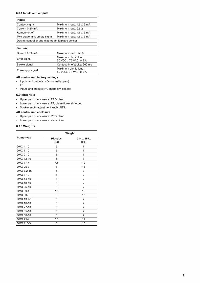
6.8.1 Inputs and outputs
AR control unit factory settings• Inputs and outputs: NO (normally open)
or• inputs and outputs: NC (normally closed).
6.9 Materials• Upper part of enclosure: PPO blend• Lower part of enclosure: PP, glass-fibre-reinforced• Stroke-length adjustment knob: ABS.
AR control unit enclosure• Upper part of enclosure: PPO blend• Lower part of enclosure: aluminium.
6.10 Weights
Inputs
Contact signal Maximum load: 12 V, 5 mACurrent 0-20 mA Maximum load: 22 ΩRemote on/off Maximum load: 12 V, 5 mATwo-stage tank-empty signal Maximum load: 12 V, 5 mADosing controller and diaphragm leakage sensor
Outputs
Current 0-20 mA Maximum load: 350 Ω
Error signal Maximum ohmic load: 50 VDC / 75 VAC, 0.5 A
Stroke signal Contact time/stroke: 200 ms
Pre-empty signal Maximum ohmic load: 50 VDC / 75 VAC, 0.5 A
Pump typeWeight
Plastics[kg]
DIN 1.4571[kg]
DMX 4-10 5 7DMX 7-10 5 7DMX 9-10 5 7DMX 12-10 5 7DMX 17-4 7.5 12DMX 25-3 8 13DMX 7.2-16 5 7DMX 8-10 5 7DMX 14-10 5 7DMX 18-10 5 7DMX 26-10 5 7DMX 39-4 7.5 12DMX 60-3 8 13DMX 13.7-16 5 7DMX 16-10 5 7DMX 27-10 5 7DMX 35-10 5 7DMX 50-10 5 7DMX 75-4 7.5 12DMX 115-3 8 13
11
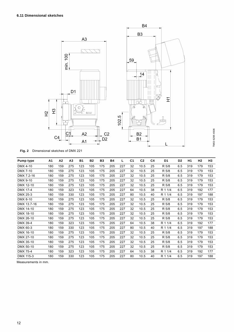
6.11 Dimensional sketches
Fig. 2 Dimensional sketches of DMX 221
Measurements in mm.
TM03
629
5 45
06
A3
B4
B3
59
14
D1
C4C1 A2
A1
C2D2
B2B1
L
min
. 100
H2 H
3
102.
5
H1
Pump type A1 A2 A3 B1 B2 B3 B4 L C1 C2 C4 D1 D2 H1 H2 H3
DMX 4-10 180 159 275 123 105 175 205 227 32 10.5 25 R 5/8 6.5 319 179 153DMX 7-10 180 159 275 123 105 175 205 227 32 10.5 25 R 5/8 6.5 319 179 153DMX 7.2-16 180 159 275 123 105 175 205 227 32 10.5 25 R 5/8 6.5 319 179 153DMX 9-10 180 159 275 123 105 175 205 227 32 10.5 25 R 5/8 6.5 319 179 153DMX 12-10 180 159 275 123 105 175 205 227 32 10.5 25 R 5/8 6.5 319 179 153DMX 17-4 180 159 323 123 105 175 205 227 64 10.5 38 R 1 1/4 6.5 319 192 177DMX 25-3 180 159 330 123 105 175 205 227 80 10.5 40 R 1 1/4 6.5 319 197 188DMX 8-10 180 159 275 123 105 175 205 227 32 10.5 25 R 5/8 6.5 319 179 153DMX 13.7-16 180 159 275 123 105 175 205 227 32 10.5 25 R 5/8 6.5 319 179 153DMX 14-10 180 159 275 123 105 175 205 227 32 10.5 25 R 5/8 6.5 319 179 153DMX 18-10 180 159 275 123 105 175 205 227 32 10.5 25 R 5/8 6.5 319 179 153DMX 26-10 180 159 275 123 105 175 205 227 32 10.5 25 R 5/8 6.5 319 179 153DMX 39-4 180 159 323 123 105 175 205 227 64 10.5 38 R 1 1/4 6.5 319 192 177DMX 60-3 180 159 330 123 105 175 205 227 80 10.5 40 R 1 1/4 6.5 319 197 188DMX 16-10 180 159 275 123 105 175 205 227 32 10.5 25 R 5/8 6.5 319 179 153DMX 27-10 180 159 275 123 105 175 205 227 32 10.5 25 R 5/8 6.5 319 179 153DMX 35-10 180 159 275 123 105 175 205 227 32 10.5 25 R 5/8 6.5 319 179 153DMX 50-10 180 159 275 123 105 175 205 227 32 10.5 25 R 5/8 6.5 319 179 153DMX 75-4 180 159 323 123 105 175 205 227 64 10.5 38 R 1 1/4 6.5 319 192 177DMX 115-3 180 159 330 123 105 175 205 227 80 10.5 40 R 1 1/4 6.5 319 197 188
12
7. Transport and storage
7.1 DeliveryThe DMX 221 dosing pumps are supplied in different packaging, depending on pump type and the overall delivery. For transport and intermediate storage, use the correct packaging to protect the pump against damage.
7.2 Intermediate storage• Permissible storage temperature: –20 °C to +50 °C.• Permissible air humidity: max. relative humidity: 92 %
(non-condensing).
7.3 UnpackingRetain the packaging for future storage or return, or dispose of the packaging in accordance with local regulations.
7.4 ReturnReturn the pump in its original packaging or equivalent. The pump must be thoroughly cleaned before it is returned or stored. It is essential that there are no traces of toxic or hazardous media remaining on the pump.
Before returning the pump to Grundfos Alldos for service, the safety declaration at the end of these instructions must be filled in by authorised personnel and attached to the pump in a visible position.
If Grundfos Alldos is requested to service the pump, it must be ensured that the pump is free from substances that can be injurious to health or toxic. If the pump has been used for such substances, the pump must be cleaned before it is returned. If proper cleaning is not possible, all relevant information about the chemical must be provided.If the above is not fulfilled, Grundfos Alldos can refuse to accept the pump for service. Costs of returning the pump are paid by the customer. The safety declaration can be found at the end of these instructions.
Caution
Do not throw or drop the pump.Store the pump in a dry and cool place.Store the pump in upright position so that the gear grease cannot leak out.Do not use the protective packaging as transport packaging.Observe the permissible storage temperature!
CautionGrundfos Alldos accepts no liability for damage caused by incorrect transportation or missing or unsuitable packaging of the pump!
CautionIf a pump has been used for a medium which is injurious to health or toxic, the pump will be classified as contaminated.
CautionThe replacement of the supply cable must be carried out by an authorised Grundfos Alldos service workshop.
13
8. Installation
8.1 Optimum installation
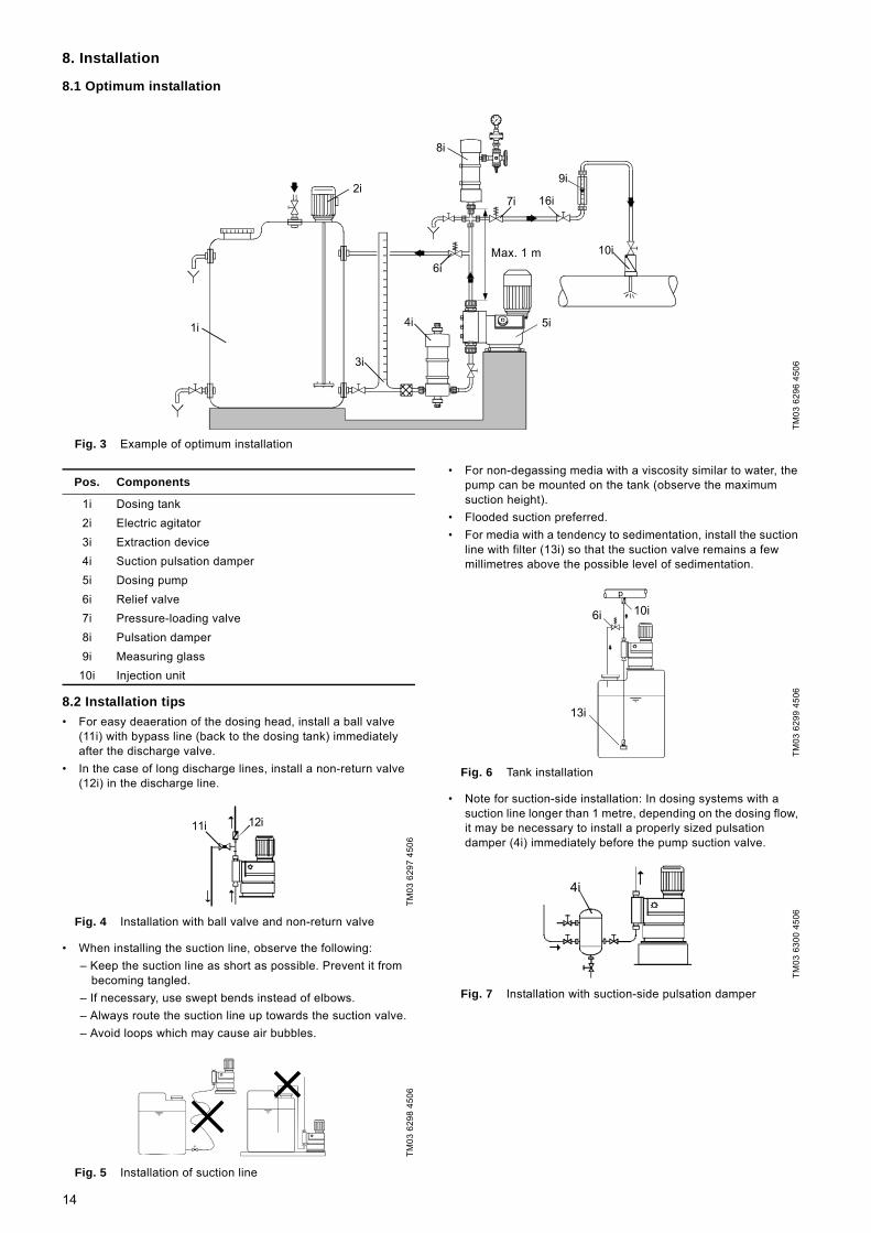
Fig. 3 Example of optimum installation
8.2 Installation tips• For easy deaeration of the dosing head, install a ball valve
(11i) with bypass line (back to the dosing tank) immediately after the discharge valve.
• In the case of long discharge lines, install a non-return valve (12i) in the discharge line.
Fig. 4 Installation with ball valve and non-return valve
• When installing the suction line, observe the following:– Keep the suction line as short as possible. Prevent it from
becoming tangled. – If necessary, use swept bends instead of elbows.– Always route the suction line up towards the suction valve.– Avoid loops which may cause air bubbles.
Fig. 5 Installation of suction line
• For non-degassing media with a viscosity similar to water, the pump can be mounted on the tank (observe the maximum suction height).
• Flooded suction preferred.• For media with a tendency to sedimentation, install the suction
line with filter (13i) so that the suction valve remains a few millimetres above the possible level of sedimentation.
Fig. 6 Tank installation
• Note for suction-side installation: In dosing systems with a suction line longer than 1 metre, depending on the dosing flow, it may be necessary to install a properly sized pulsation damper (4i) immediately before the pump suction valve.
Fig. 7 Installation with suction-side pulsation damper
TM03
629
6 45
06
1i
2i
3i
4i 5i
6i
9i
10i
8i
max. 1m
16i7i
Max. 1 m
Pos. Components
1i Dosing tank2i Electric agitator3i Extraction device4i Suction pulsation damper5i Dosing pump6i Relief valve7i Pressure-loading valve8i Pulsation damper 9i Measuring glass
10i Injection unit
TM03
629
7 45
06TM
03 6
298
4506
11i 12i
TM03
629
9 45
06TM
03 6
300
4506
p
10i6i
13i
4i
14
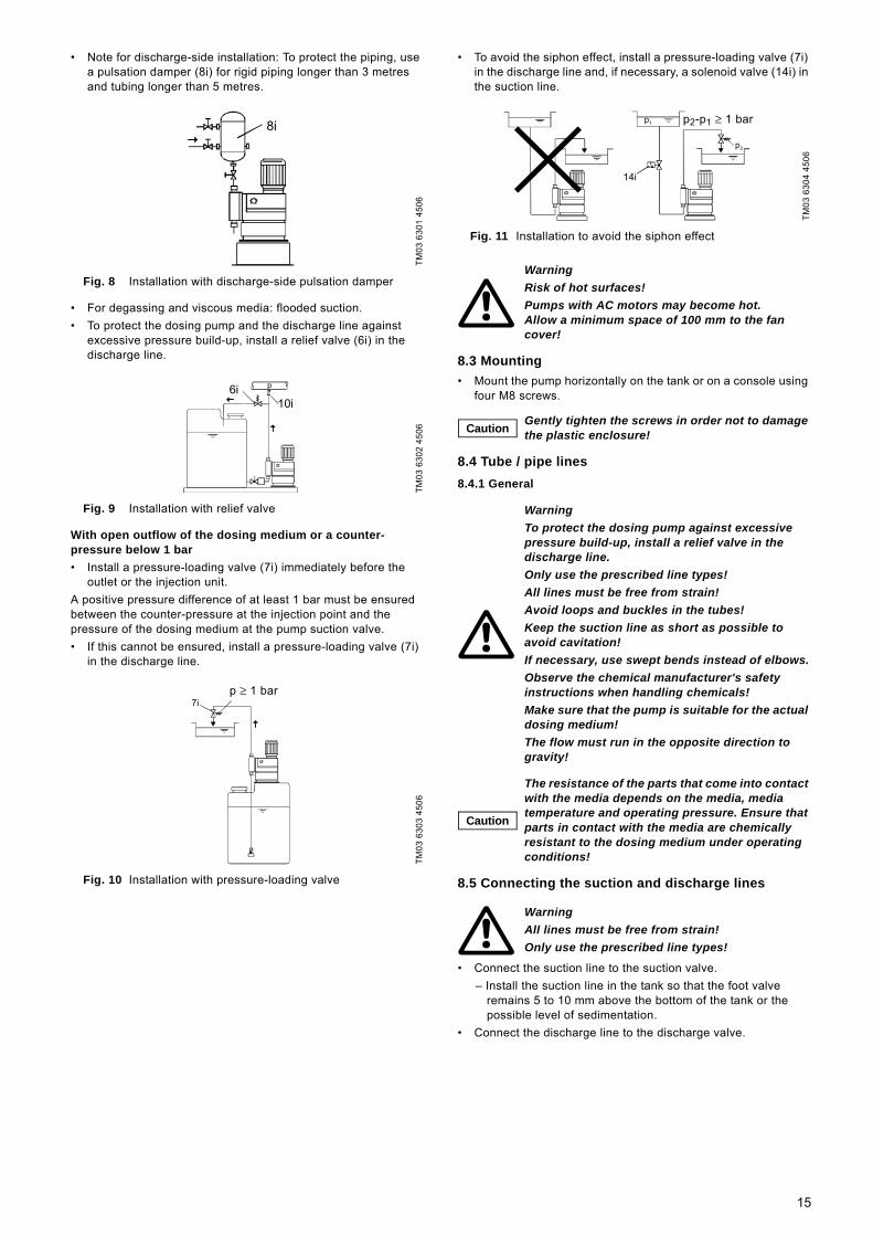
• Note for discharge-side installation: To protect the piping, use a pulsation damper (8i) for rigid piping longer than 3 metres and tubing longer than 5 metres.
Fig. 8 Installation with discharge-side pulsation damper
• For degassing and viscous media: flooded suction.• To protect the dosing pump and the discharge line against
excessive pressure build-up, install a relief valve (6i) in the discharge line.
Fig. 9 Installation with relief valve
With open outflow of the dosing medium or a counter-pressure below 1 bar• Install a pressure-loading valve (7i) immediately before the
outlet or the injection unit.A positive pressure difference of at least 1 bar must be ensured between the counter-pressure at the injection point and the pressure of the dosing medium at the pump suction valve. • If this cannot be ensured, install a pressure-loading valve (7i)
in the discharge line.
Fig. 10 Installation with pressure-loading valve
• To avoid the siphon effect, install a pressure-loading valve (7i) in the discharge line and, if necessary, a solenoid valve (14i) in the suction line.
Fig. 11 Installation to avoid the siphon effect
8.3 Mounting• Mount the pump horizontally on the tank or on a console using
four M8 screws.
8.4 Tube / pipe lines8.4.1 General
8.5 Connecting the suction and discharge lines
• Connect the suction line to the suction valve.– Install the suction line in the tank so that the foot valve
remains 5 to 10 mm above the bottom of the tank or the possible level of sedimentation.
• Connect the discharge line to the discharge valve.
TM03
630
1 45
06TM
03 6
302
4506
TM03
630
3 45
06
8i
6i10i
p
7ip 1 barp ≥ 1 bar
TM03
630
4 45
06
WarningRisk of hot surfaces! Pumps with AC motors may become hot. Allow a minimum space of 100 mm to the fan cover!
Caution Gently tighten the screws in order not to damage the plastic enclosure!
WarningTo protect the dosing pump against excessive pressure build-up, install a relief valve in the discharge line.Only use the prescribed line types! All lines must be free from strain! Avoid loops and buckles in the tubes!Keep the suction line as short as possible to avoid cavitation!If necessary, use swept bends instead of elbows.Observe the chemical manufacturer's safety instructions when handling chemicals!Make sure that the pump is suitable for the actual dosing medium!The flow must run in the opposite direction to gravity!
Caution
The resistance of the parts that come into contact with the media depends on the media, media temperature and operating pressure. Ensure that parts in contact with the media are chemically resistant to the dosing medium under operating conditions!
WarningAll lines must be free from strain!Only use the prescribed line types!
14i
p1
p2
2 p - p1 1 bar>_p2-p1 ≥ 1 bar
15
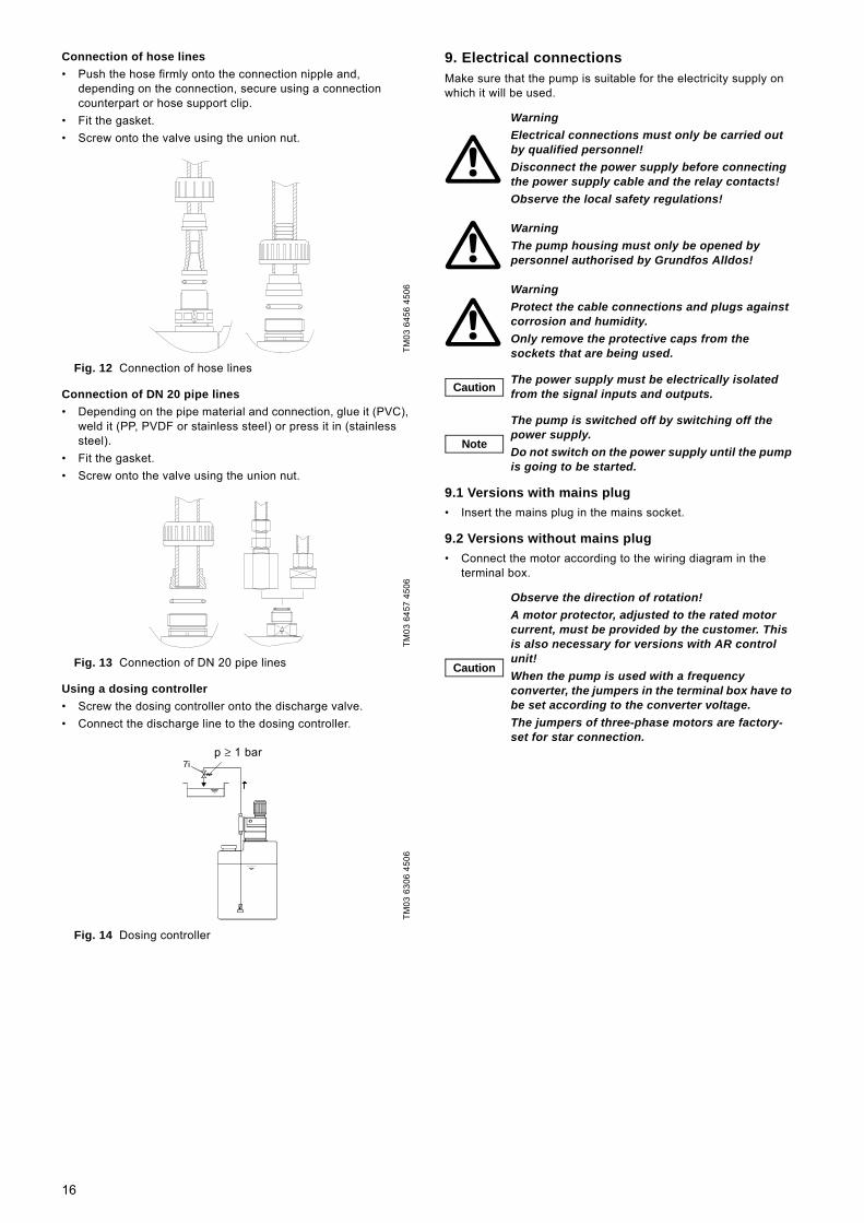
Connection of hose lines• Push the hose firmly onto the connection nipple and,
depending on the connection, secure using a connection counterpart or hose support clip.
• Fit the gasket.• Screw onto the valve using the union nut.
Fig. 12 Connection of hose lines
Connection of DN 20 pipe lines• Depending on the pipe material and connection, glue it (PVC),
weld it (PP, PVDF or stainless steel) or press it in (stainless steel).
• Fit the gasket.• Screw onto the valve using the union nut.
Fig. 13 Connection of DN 20 pipe lines
Using a dosing controller• Screw the dosing controller onto the discharge valve.• Connect the discharge line to the dosing controller.
Fig. 14 Dosing controller
9. Electrical connectionsMake sure that the pump is suitable for the electricity supply on which it will be used.
9.1 Versions with mains plug• Insert the mains plug in the mains socket.
9.2 Versions without mains plug• Connect the motor according to the wiring diagram in the
terminal box.
TM03
645
6 45
06TM
03 6
457
4506
TM03
630
6 45
06
7ip 1 barp ≥ 1 bar
WarningElectrical connections must only be carried out by qualified personnel!Disconnect the power supply before connecting the power supply cable and the relay contacts!Observe the local safety regulations!
WarningThe pump housing must only be opened by personnel authorised by Grundfos Alldos!
WarningProtect the cable connections and plugs against corrosion and humidity.Only remove the protective caps from the sockets that are being used.
Caution The power supply must be electrically isolated from the signal inputs and outputs.
Note
The pump is switched off by switching off the power supply.Do not switch on the power supply until the pump is going to be started.
Caution
Observe the direction of rotation!A motor protector, adjusted to the rated motor current, must be provided by the customer. This is also necessary for versions with AR control unit!When the pump is used with a frequency converter, the jumpers in the terminal box have to be set according to the converter voltage.The jumpers of three-phase motors are factory-set for star connection.
16
10. Commissioning
10.1 Checks before start-up• Check that the rated voltage stated on the pump nameplate
corresponds to the local conditions! • Check that all connections are secure and tighten,
if necessary.• Check that the dosing head screws are tightened with the
specified torque and tighten, if necessary.• Check that all electrical connections are correct.
10.2 Start-up
1. Open the suction and discharge isolating valves (15, 16), if installed.
2. Open the deaeration valve (17), if installed, in the discharge line, or relieve the pressure on the discharge side so that the medium can run out without a counter-pressure.
3. Switch on the power supply.4. Pumps with AR control unit only: Press the "Start/Stop" button
and keep it pressed.– The pump switches to continuous operation.
5. Set the stroke-length adjustment knob to 100 %.6. Leave the pump running until the dosed medium is free of air
bubbles.7. Close the deaeration valve (17), if installed.
– The pump is now ready for operation.
Fig. 15 Initial start-up
11. Operation
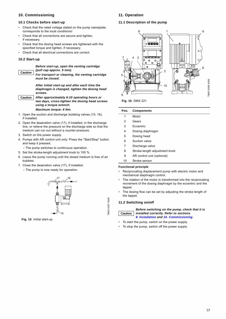
11.1 Description of the pump
Fig. 16 DMX 221
Functional principle• Reciprocating displacement pump with electric motor and
mechanical diaphragm control.• The rotation of the motor is transformed into the reciprocating
movement of the dosing diaphragm by the eccentric and the tappet.
• The dosing flow can be set by adjusting the stroke length of the tappet.
11.2 Switching on/off
• To start the pump, switch on the power supply.• To stop the pump, switch off the power supply.
Caution
Before start-up, open the venting cartridge (pull cap approx. 5 mm). For transport or cleaning, the venting cartridge must be closed.
Caution
After initial start-up and after each time the diaphragm is changed, tighten the dosing head screws.After approximately 6-10 operating hours or two days, cross-tighten the dosing head screws using a torque wrench.Maximum torque: 6 Nm.
TM03
630
7 45
06
1617
15
TM03
630
8 45
06
Pos. Components
1 Motor2 Gears3 Eccentric4 Dosing diaphragm5 Dosing head6 Suction valve7 Discharge valve8 Stroke-length adjustment knob9 AR control unit (optional)
10 Stroke sensor
CautionBefore switching on the pump, check that it is installed correctly. Refer to sections 8. Installation and 10. Commissioning.
1
2
34
5
6
7
8
9
10
9
17

11.3 Adjusting the dosing flow via the stroke length
• To increase the dosing flow, turn the stroke-length adjustment knob (8) slowly to the left until the desired dosing flow is reached.
• To decrease the dosing flow, turn the stroke-length adjustment knob (8) slowly to the right until the desired dosing flow is reached.
Fig. 17 Stroke-length adjustment knob
11.4 Stroke-length adjustment
The zero point (no dosing) of the dosing pump is factory-set to a counter-pressure of 3 bar. See section 16. Dosing curves.If the operating counter-pressure at the injection unit deviates considerably from this value, it is advisable to readjust the zero point to obtain more precise values.1. Install a graduated tube at the suction valve.
– If such a tube is not available, insert the suction line into a graduated measuring jug.
2. Start the dosing pump.3. Set the dosing flow to 15 %.4. For pumps with tank-empty indication, remove the electric plug
of the tank-empty indication.5. Turn the adjustment knob slowly clockwise (towards the zero
point) until the medium level stops falling in the measuring jug or tube.
6. Remove the plug with a small screwdriver without changing the position of the adjustment knob and unscrew the cheese-head screw together with the flat spiral spring.
7. Gently pull off the adjustment knob and fit it on the adjusting spindle so that the zero line on the scale and the mark on the adjustment knob coincide.
8. Screw in the cheese-head screw and the spiral spring until the spring is preloaded, but does not block. Even when adjusted to 100 %, the spring of the adjustment knob must remain preloaded.
Fig. 18 Stroke-length adjustment
11.5 Adjustment of stroke rate using a frequency converter
If a frequency converter is connected, the stroke rate can only be adjusted in the range 10-100 % of max. stroke rate. See installation and operating instructions for the frequency converter!
Settings of frequency converter when used with Grundfos Alldos dosing pumpsPay special attention to the following parameters of the frequency converter:• P013 (maximum motor frequency):
– Set the frequency converter to maximum 100 Hz.– Due to this setting, the maximum stroke frequency of the
pump cannot be exceeded.• P086 (motor current limit):
– Do not change the default setting (150 %).– The motor is protected by a PTC resistor. Therefore, this
parameter is not necessary.• P081 - P085 (motor data):
– Set these parameters to the values stated on the motor nameplate.
– Observe the manufacturer’s instructions!
11.6 Using the AR control unitWhen using the AR control unit, observe the installation and operating instructions for "AR control unit" in addition to the instructions in this manual.
12. Operation with other electronics
12.1 Electronics version stroke sensorPump type with inductive-proximity switch of two-wire design according to NAMUR DIN 19234 for signalling the strokes.The sensor can be installed in potentially explosive atmospheres if PTB-approved isolating switching amplifiers with an intrinsically safe control circuit [EExia] or [EExib] are connected. The sensor can be used up to zone 1 depending on the isolating amplifier. The specifications in the declaration of conformity for the isolating amplifier must be observed.Supply voltage UB: 7.7 to 10 V.
Caution Adjust the stroke length only while the pump is running!
TM03
630
9 45
06WarningWear protective clothing (gloves and goggles) when working on the dosing head, connections or lines!
Caution Adjust the stroke length only while the pump is running!
TM03
631
0 45
06
100%
90
80
70
60 50 40
30
20
10
0
8
WarningObserve the manufacturer’s instructions! The connections must be carried out according to these instructions.
CautionFirst refer to the general section 11. Operation. This section only describes the additional functions.
18
13. Integral relief valve
13.1 FunctionIf the pump is the only pump in the system, the integral relief valve (optional) protects the complete discharge side of the discharge line system from an excessive pressure build-up.The valve opens if the pressure rises above its set opening pressure, and the dosing medium can return to the dosing tank.In contrast to relief valves connected in series, the integral valve also provides pump protection if the discharge valve is dirty or blocked.
13.2 Permissible media
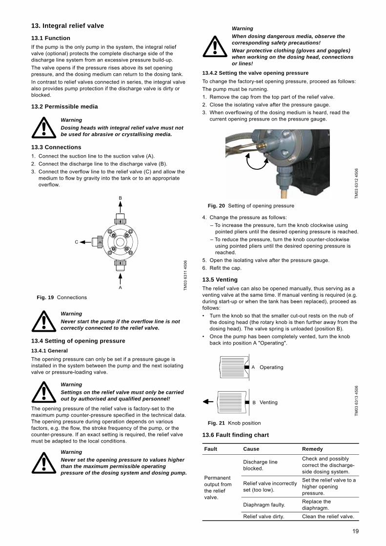
13.3 Connections1. Connect the suction line to the suction valve (A).2. Connect the discharge line to the discharge valve (B).3. Connect the overflow line to the relief valve (C) and allow the
medium to flow by gravity into the tank or to an appropriate overflow.
Fig. 19 Connections
13.4 Setting of opening pressure13.4.1 GeneralThe opening pressure can only be set if a pressure gauge is installed in the system between the pump and the next isolating valve or pressure-loading valve.
The opening pressure of the relief valve is factory-set to the maximum pump counter-pressure specified in the technical data. The opening pressure during operation depends on various factors, e.g. the flow, the stroke frequency of the pump, or the counter-pressure. If an exact setting is required, the relief valve must be adapted to the local conditions.
13.4.2 Setting the valve opening pressureTo change the factory-set opening pressure, proceed as follows:The pump must be running.1. Remove the cap from the top part of the relief valve.2. Close the isolating valve after the pressure gauge.3. When overflowing of the dosing medium is heard, read the
current opening pressure on the pressure gauge.
Fig. 20 Setting of opening pressure
4. Change the pressure as follows:– To increase the pressure, turn the knob clockwise using
pointed pliers until the desired opening pressure is reached.– To reduce the pressure, turn the knob counter-clockwise
using pointed pliers until the desired opening pressure is reached.
5. Open the isolating valve after the pressure gauge.6. Refit the cap.
13.5 VentingThe relief valve can also be opened manually, thus serving as a venting valve at the same time. If manual venting is required (e.g. during start-up or when the tank has been replaced), proceed as follows:• Turn the knob so that the smaller cut-out rests on the nub of
the dosing head (the rotary knob is then further away from the dosing head). The valve spring is unloaded (position B).
• Once the pump has been completely vented, turn the knob back into position A "Operating".
Fig. 21 Knob position
13.6 Fault finding chart
WarningDosing heads with integral relief valve must not be used for abrasive or crystallising media.
TM03
631
1 45
06
WarningNever start the pump if the overflow line is not correctly connected to the relief valve.
WarningSettings on the relief valve must only be carried out by authorised and qualified personnel!
WarningNever set the opening pressure to values higher than the maximum permissible operating pressure of the dosing system and dosing pump.
A
B
C
WarningWhen dosing dangerous media, observe the corresponding safety precautions!Wear protective clothing (gloves and goggles) when working on the dosing head, connections or lines!
TM03
631
2 45
06TM
03 6
313
4506
Fault Cause Remedy
Permanent output from the relief valve.
Discharge line blocked.
Check and possibly correct the discharge-side dosing system.
Relief valve incorrectly set (too low).
Set the relief valve to a higher opening pressure.
Diaphragm faulty. Replace the diaphragm.
Relief valve dirty. Clean the relief valve.
A
B
Operating
Venting
19
14. Maintenance
14.1 General notes
14.2 Changing the gear grease
To ensure trouble-free operation, it is recommended to have the gear grease changed after five years or after 20,000 operating hours.
14.2.1 Cleaning and maintenance intervalsClean the diaphragm and valves, or replace if necessary (with stainless-steel valves: inner valve parts): • regularly every 12 months or after 4,000 operating hours.
When operating with a counter-pressure of 16 bar, every six months or after 2,000 operating hours, or
• in case of malfunction.
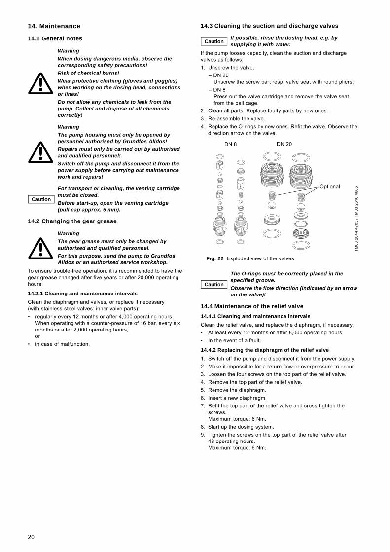
14.3 Cleaning the suction and discharge valves
If the pump looses capacity, clean the suction and discharge valves as follows:1. Unscrew the valve.
– DN 20Unscrew the screw part resp. valve seat with round pliers.
– DN 8Press out the valve cartridge and remove the valve seat from the ball cage.
2. Clean all parts. Replace faulty parts by new ones.3. Re-assemble the valve.4. Replace the O-rings by new ones. Refit the valve. Observe the
direction arrow on the valve.
Fig. 22 Exploded view of the valves
14.4 Maintenance of the relief valve14.4.1 Cleaning and maintenance intervalsClean the relief valve, and replace the diaphragm, if necessary.• At least every 12 months or after 8,000 operating hours.• In the event of a fault.
14.4.2 Replacing the diaphragm of the relief valve1. Switch off the pump and disconnect it from the power supply.2. Make it impossible for a return flow or overpressure to occur.3. Loosen the four screws on the top part of the relief valve.4. Remove the top part of the relief valve.5. Remove the diaphragm.6. Insert a new diaphragm.7. Refit the top part of the relief valve and cross-tighten the
screws.Maximum torque: 6 Nm.
8. Start up the dosing system.9. Tighten the screws on the top part of the relief valve after
48 operating hours.Maximum torque: 6 Nm.
WarningWhen dosing dangerous media, observe the corresponding safety precautions!Risk of chemical burns!Wear protective clothing (gloves and goggles) when working on the dosing head, connections or lines!Do not allow any chemicals to leak from the pump. Collect and dispose of all chemicals correctly!
WarningThe pump housing must only be opened by personnel authorised by Grundfos Alldos! Repairs must only be carried out by authorised and qualified personnel!Switch off the pump and disconnect it from the power supply before carrying out maintenance work and repairs!
Caution
For transport or cleaning, the venting cartridge must be closed. Before start-up, open the venting cartridge (pull cap approx. 5 mm).
WarningThe gear grease must only be changed by authorised and qualified personnel. For this purpose, send the pump to Grundfos Alldos or an authorised service workshop.
Caution If possible, rinse the dosing head, e.g. by supplying it with water.
TM03
264
4 47
05 /
TM03
261
0 46
05
Caution
The O-rings must be correctly placed in the specified groove.Observe the flow direction (indicated by an arrow on the valve)!
Optional
DN 20DN 8
20
14.5 Replacing the diaphragm
14.5.1 Switching off the pump1. While the pump is running, set the stroke-length adjustment
knob to 100 %.2. Switch off the pump and disconnect it from the power supply.3. Depressurise the system.4. Take suitable steps to ensure that the returning dosing
medium is safely collected.
14.5.2 Replacing the diaphragm1. Loosen the six dosing head screws.2. Remove the dosing head.3. Turn the fan blades until the diaphragm reaches the front dead
centre (the diaphragm detaches itself from the diaphragm flange).
4. Unscrew the diaphragm by manually turning it counter-clockwise.
5. Check the parts and replace by new ones, if necessary.6. Screw in the new diaphragm completely. Then turn it back until
the holes in the diaphragm and the flange coincide.7. Turn the fan blades until the diaphragm reaches the bottom
dead centre (the diaphragm is pulled onto the diaphragm flange).
8. Refit the dosing head carefully and cross-tighten the screws.Maximum torque: 6 Nm.
9. Deaerate and start the dosing pump.
Caution Adjust the stroke length only while the pump is running!
Caution For transport or cleaning, the venting cartridge must be closed.
Note If possible, rinse the dosing head, e.g. by supplying it with water.
Caution Before start-up, open the venting cartridge (pull cap approx. 5 mm).
Caution
After initial start-up and after each time the diaphragm is changed, tighten the dosing head screws.After approximately 6-10 operating hours or two days, cross-tighten the dosing head screws using a torque wrench.Maximum torque: 6 Nm.
21
15. Fault finding chart
Fault Cause Remedy
1. Dosing pump does not run.
a) Not connected to the power supply. Connect the power supply cable.b) Incorrect supply voltage. Replace the dosing pump.c) Electrical failure. Return the pump for repair.d) The empty indication has responded. Remove the cause.e) The diaphragm leakage detection has responded. Replace the diaphragm.
2. Dosing pump does not suck in.
a) Leaking suction line. Replace or seal the suction line.b) Cross-section of the suction line too small or
suction line too long. Check with Grundfos Alldos specification.
c) Clogged suction line. Rinse or replace the suction line.d) Foot valve covered by sediment. Suspend the suction line from a higher position.e) Buckled suction line. Install the suction line correctly. Check for
damage.f) Crystalline deposits in the valves. Clean the valves.g) Diaphragm broken or diaphragm tappet torn out. Replace the diaphragm.
3. Dosing pump does not dose.
a) Air in the suction line and dosing head. Wait, until the pump has deaerated.b) Stroke-length adjustment knob set to zero. Turn the adjustment knob in the "+" direction.c) Viscosity or density of medium too high. Check the installation.d) Crystalline deposits in the valves. Clean the valves.e) Valves not correctly assembled. Assemble the inner valve parts in the right order
and check and possibly correct the flow direction.
f) Injection point blocked. Check and possibly correct the flow direction (injection unit), or remove the obstruction.
g) Incorrect installation of lines and peripheral equipment.
Check the lines for free passage and correct installation.
4. Dosing flow of the pump is inaccurate.
a) Dosing head not fully deaerated. Repeat the deareation.b) Degassing medium. Check the installation.c) Parts of the valves covered in dirt or incrusted. Clean the valves.d) Zero point misadjusted. Adjust the zero point to the actual counter-
pressure.e) Counter-pressure fluctuations. Install a pressure-loading valve and a pulsation
damper.f) Suction height fluctuations. Keep the suction level constant.g) Siphon effect (inlet pressure higher than counter-
pressure). Install a pressure-loading valve.
h) Leaking or porous suction line or discharge line. Replace the suction line or discharge line.i) Parts in contact with the medium are not resistant
to it. Replace with resistant materials.
j) Dosing diaphragm worn (incipient tears). Replace the diaphragm. Also observe the maintenance instructions.
k) Supply voltage fluctuations. Decrease the counter-pressure of the pump.l) Variation of the dosing medium (density,
viscosity).Check the concentration. Use an agitator, if necessary.
Caution For further error signals for the control unit, refer to the relevant section.
22
16. Dosing curvesThe dosing curves on the following pages are trend curves.They apply to:• performance of simple pump (the flow rate is doubled for the
double pump)• water as dosing medium• suction line with foot valve, 0.5 m flooded suction• zero point of pump Q0 for specified pressure, see table below• standard pump version.
Fig. 23 DMX 4-10 (50 Hz)
Fig. 24 DMX 4-10 (60 Hz)
Fig. 25 DMX 7-10 (50 Hz)
Fig. 26 DMX 7-10 (60 Hz)
Fig. 27 DMX 7.2-16 (50 Hz)
Fig. 28 DMX 7.2-16 (60 Hz)
Fig. 29 DMX 9-10 (50 Hz)
Fig. 30 DMX 9-10 (60 Hz)
Fig. 31 DMX 12-10 (50 Hz)
Abbreviation Description
Q Dosing flow
Q0Zero point of the pumpThe pumps are calibrated so that Q is 0 at 3 bar.
h Stroke length
TM03
631
5 45
06TM
03 6
316
4506
TM03
631
7 45
06TM
03 6
318
4506
0
1
2
3
4
5
6
0 10 20 30 40 50 60 70 80 90 100h [%]
Q [l/h]
3bar
10bar
3 bar10 bar
( ) 0
0
1
2
3
4
5
6
0 10 20 30 40 50 60 70 80 90 100h [%]
Q [l/h]
10bar
3bar
3 bar10 bar
0
2
4
6
8
10
0 10 20 30 40 50 60 70 80 90 100h [%]
Q [l/h]
3bar
10bar
3 bar10 bar
0
2
4
6
8
10
0 10 20 30 40 50 60 70 80 90 100h [%]
Q [l/h]
10bar
3bar
3 bar10 bar
TM03
631
9 45
06TM
03 6
320
4506
TM03
632
1 45
06TM
03 6
322
4506
TM03
632
3 45
06
( ) 0
0
2
4
6
8
10
12
0 10 20 30 40 50 60 70 80 90 100h [%]
Q [l/h]
3bar
16bar3 bar16 bar
0
0
2
4
6
8
10
12
0 10 20 30 40 50 60 70 80 90 100h [%]
Q [l/h]
16bar
3bar
3 bar16 bar
0
2
4
6
8
10
12
0 10 20 30 40 50 60 70 80 90 100h [%]
Q [l/h]
3bar
10bar
3 bar10 bar
0
2
4
6
8
10
12
0 10 20 30 40 50 60 70 80 90 100h [%]
Q [l/h]
10bar
3bar
3 bar10 bar
02468
1012141618
0 10 20 30 40 50 60 70 80 90 100h [%]
Q [l/h]
3bar
10bar
3 bar10 bar
23
Fig. 32 DMX 12-10 (60 Hz)
Fig. 33 DMX 17-4 (50 Hz)
Fig. 34 DMX 17-4 (60 Hz)
Fig. 35 DMX 25-3 (50 Hz)
Fig. 36 DMX 25-3 (60 Hz)
Fig. 37 DMX 8-10 (50 Hz)
Fig. 38 DMX 8-10 (60 Hz)
Fig. 39 DMX 13.7-16 (50 Hz)
Fig. 40 DMX 13.7-16 (60 Hz)
Fig. 41 DMX 14-10 (50 Hz)
TM03
632
4 45
06TM
03 6
325
4506
TM03
632
6 45
06TM
03 6
327
4506
TM03
632
8 45
06
02468
1012141618
0 10 20 30 40 50 60 70 80 90 100h [%]
Q [l/h]
10bar
3bar
3 bar10 bar
( ) 0
0
4
8
12
16
20
24
0 10 20 30 40 50 60 70 80 90 100h [%]
Q [l/h]
3bar
4bar
1,5bar
3 bar4 bar1.5 bar
0
4
8
12
16
20
24
0 10 20 30 40 50 60 70 80 90 100h [%]
Q [l/h]
4bar
3bar
1,5bar
3 bar4 bar1.5 bar
0
5
10
15
20
25
30
35
0 10 20 30 40 50 60 70 80 90 100h [%]
Q [l/h]
1,5bar
3bar
3 bar1.5 bar
0
5
10
15
20
25
30
35
0 10 20 30 40 50 60 70 80 90 100h [%]
Q [l/h]
3bar
1,5bar
3 bar1.5 bar
TM03
632
9 45
06TM
03 6
330
4506
TM03
633
1 45
06TM
03 6
332
4506
TM03
633
3 45
06
0
2
4
6
8
10
12
0 10 20 30 40 50 60 70 80 90 100h [%]
Q [l/h]
3bar
10bar
3 bar10 bar
0
2
4
6
8
10
12
0 10 20 30 40 50 60 70 80 90 100h [%]
Q [l/h]
10bar
3bar
3 bar10 bar
0
4
8
12
16
20
24
0 10 20 30 40 50 60 70 80 90 100h [%]
Q [l/h]
3bar
16bar
3 bar16 bar
0
4
8
12
16
20
24
0 10 20 30 40 50 60 70 80 90 100h [%]
Q [l/h]
16bar
3bar
3 bar16 bar
02468
101214161820
0 10 20 30 40 50 60 70 80 90 100h [%]
Q [l/h]
3bar
10bar
3 bar10 bar
24
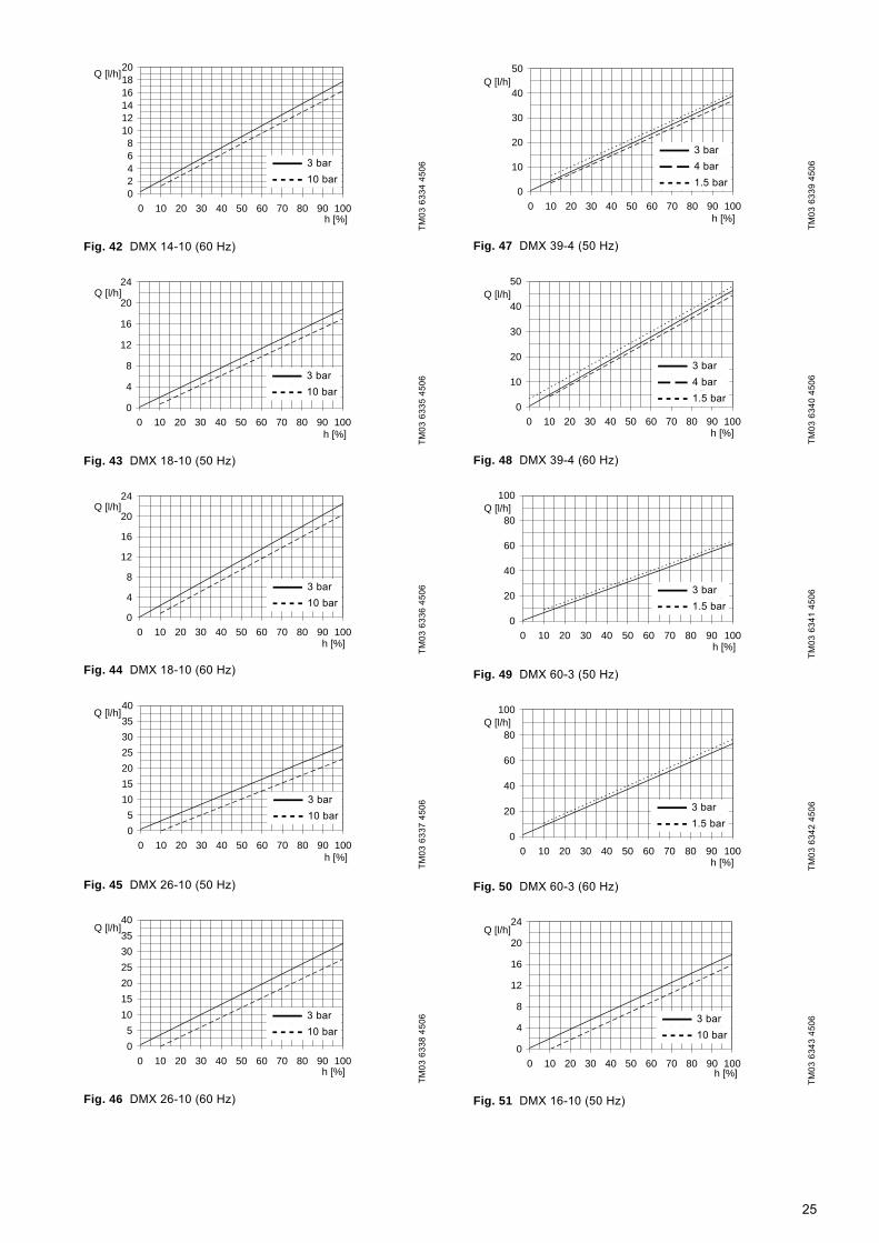
Fig. 42 DMX 14-10 (60 Hz)
Fig. 43 DMX 18-10 (50 Hz)
Fig. 44 DMX 18-10 (60 Hz)
Fig. 45 DMX 26-10 (50 Hz)
Fig. 46 DMX 26-10 (60 Hz)
Fig. 47 DMX 39-4 (50 Hz)
Fig. 48 DMX 39-4 (60 Hz)
Fig. 49 DMX 60-3 (50 Hz)
Fig. 50 DMX 60-3 (60 Hz)
Fig. 51 DMX 16-10 (50 Hz)
TM03
633
4 45
06TM
03 6
335
4506
TM03
633
6 45
06TM
03 6
337
4506
TM03
633
8 45
06
02468
101214161820
0 10 20 30 40 50 60 70 80 90 100h [%]
Q [l/h]
10bar
3bar
3 bar10 bar
0
4
8
12
16
20
24
0 10 20 30 40 50 60 70 80 90 100h [%]
Q [l/h]
3bar
10bar
3 bar10 bar
0
4
8
12
16
20
24
0 10 20 30 40 50 60 70 80 90 100h [%]
Q [l/h]
10bar
3bar3 bar10 bar
0
5
10
15
20
25
30
35
40
0 10 20 30 40 50 60 70 80 90 100h [%]
Q [l/h]
3bar
10bar
3 bar10 bar
0
5
10
15
20
25
30
35
40
0 10 20 30 40 50 60 70 80 90 100h [%]
Q [l/h]
10bar
3bar
3 bar10 bar
TM03
633
9 45
06TM
03 6
340
4506
TM03
634
1 45
06TM
03 6
342
4506
TM03
634
3 45
06
0
10
20
30
40
50
0 10 20 30 40 50 60 70 80 90 100h [%]
Q [l/h]
3bar
4bar
1,5bar
3 bar4 bar1.5 bar
0
10
20
30
40
50
0 10 20 30 40 50 60 70 80 90 100h [%]
Q [l/h]
4bar
3bar
1,5bar
3 bar4 bar1.5 bar
0
20
40
60
80
100
0 10 20 30 40 50 60 70 80 90 100h [%]
Q [l/h]
1,5bar
3bar
3 bar1.5 bar
0
20
40
60
80
100
0 10 20 30 40 50 60 70 80 90 100h [%]
Q [l/h]
3bar
1,5bar
3 bar1.5 bar
0
4
8
12
16
20
24
0 10 20 30 40 50 60 70 80 90 100h [%]
Q [l/h]
3bar
10bar
3 bar10 bar
25
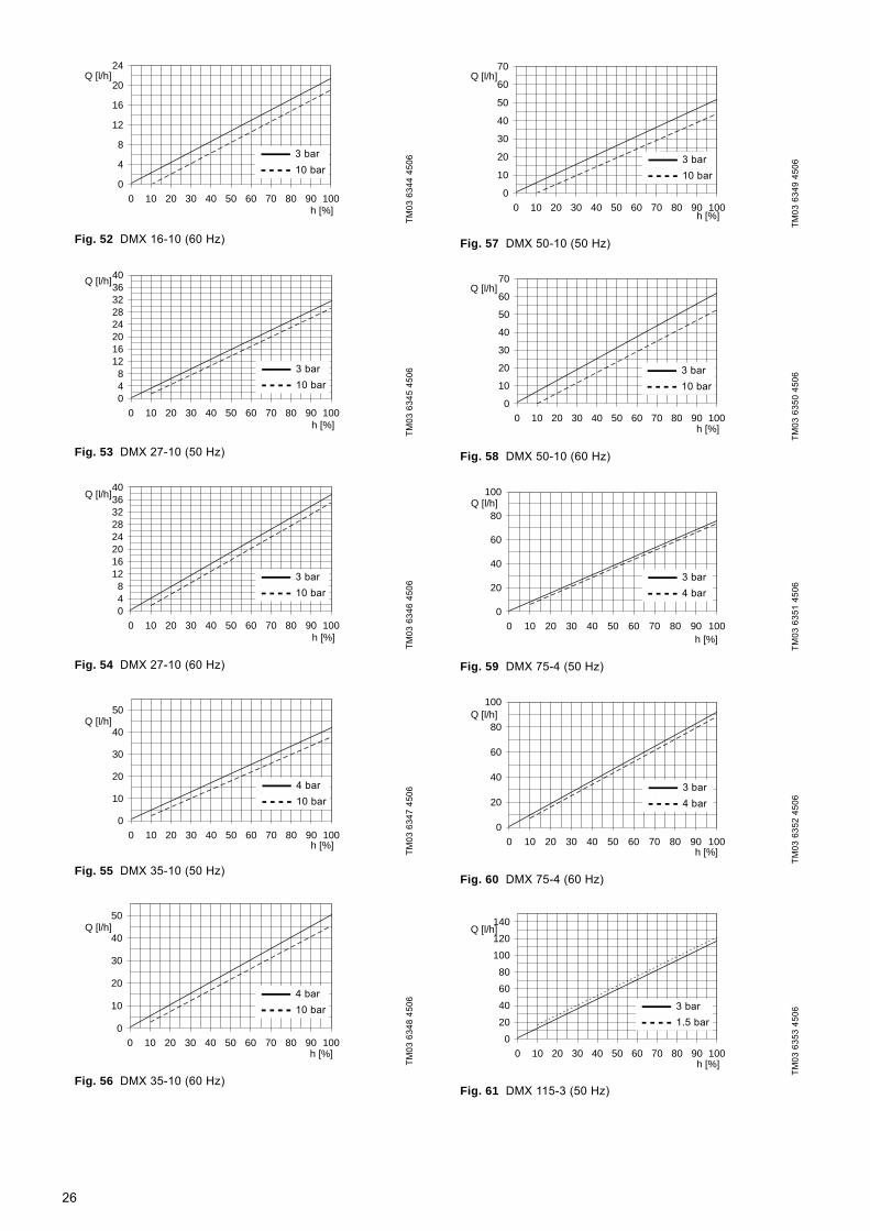
Fig. 52 DMX 16-10 (60 Hz)
Fig. 53 DMX 27-10 (50 Hz)
Fig. 54 DMX 27-10 (60 Hz)
Fig. 55 DMX 35-10 (50 Hz)
Fig. 56 DMX 35-10 (60 Hz)
Fig. 57 DMX 50-10 (50 Hz)
Fig. 58 DMX 50-10 (60 Hz)
Fig. 59 DMX 75-4 (50 Hz)
Fig. 60 DMX 75-4 (60 Hz)
Fig. 61 DMX 115-3 (50 Hz)
TM03
634
4 45
06TM
03 6
345
4506
TM03
634
6 45
06TM
03 6
347
4506
TM03
634
8 45
06
0
4
8
12
16
20
24
0 10 20 30 40 50 60 70 80 90 100h [%]
Q [l/h]
10bar
3bar
3 bar10 bar
048
1216202428323640
0 10 20 30 40 50 60 70 80 90 100h [%]
Q [l/h]
3bar
10bar
3 bar10 bar
048
1216202428323640
0 10 20 30 40 50 60 70 80 90 100h [%]
Q [l/h]
10bar
3bar
3 bar10 bar
0
10
20
30
40
50
0 10 20 30 40 50 60 70 80 90 100h [%]
Q [l/h]
4bar
10bar
4 bar10 bar
0
10
20
30
40
50
0 10 20 30 40 50 60 70 80 90 100h [%]
Q [l/h]
10bar
4bar
4 bar10 bar
TM03
634
9 45
06TM
03 6
350
4506
TM03
635
1 45
06TM
03 6
352
4506
TM03
635
3 45
06
0
10
20
30
40
50
60
70
0 10 20 30 40 50 60 70 80 90 100h [%]
Q [l/h]
3bar
10bar
3 bar10 bar
0
10
20
30
40
50
60
70
0 10 20 30 40 50 60 70 80 90 100h [%]
Q [l/h]
10bar
3bar
3 bar10 bar
0
20
40
60
80
100
0 10 20 30 40 50 60 70 80 90 100h [%]
Q [l/h]
3bar
4bar
3 bar4 bar
0
20
40
60
80
100
0 10 20 30 40 50 60 70 80 90 100h [%]
Q [l/h]
4bar
3bar
3 bar4 bar
0
20
40
60
80
100
120
140
0 10 20 30 40 50 60 70 80 90 100h [%]
Q [l/h]
1,5bar
3bar
3 bar1.5 bar
26
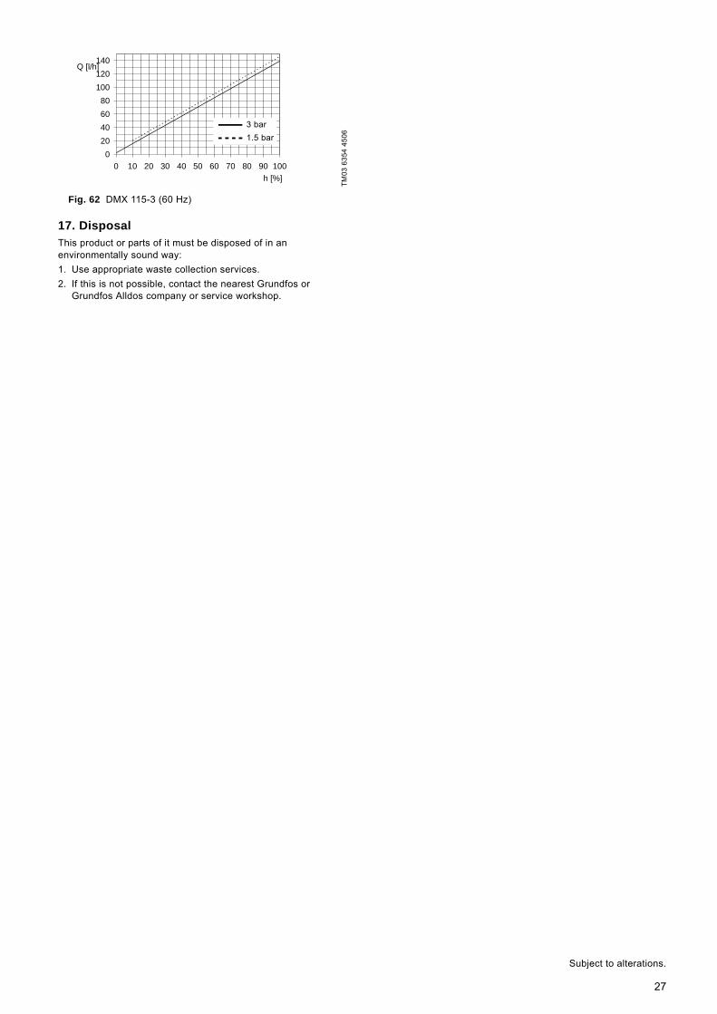
Fig. 62 DMX 115-3 (60 Hz)
17. DisposalThis product or parts of it must be disposed of in an environmentally sound way:1. Use appropriate waste collection services.2. If this is not possible, contact the nearest Grundfos or
Grundfos Alldos company or service workshop.
TM03
635
4 45
06
0
20
40
60
80
100
120
140
0 10 20 30 40 50 60 70 80 90 100
h [%]
Q [l/h]
3bar
1,5bar
3 bar1.5 bar
Subject to alterations.
27
Safety declaration
Please copy, fill in and sign this sheet and attach it to the pump returned for service.
We hereby declare that this product is free from hazardous chemicals, biological and radioactive substances:
Product type: ________________________________
Model number: _____________________________
No media or water: _____________________________
A chemical solution, name: _________________________
(see pump nameplate)
Fault descriptionPlease make a circle around the damaged part.
In the case of an electrical or functional fault, please mark the cabinet.
Please give a short description of the fault:
_____________________ _____________________Date and signature Company stamp
GrA
3476
28

29

30
DenmarkGRUNDFOS DK A/S Martin Bachs Vej 3 DK-8850 Bjerringbro Tlf.: +45-87 50 50 50 Telefax: +45-87 50 51 51 E-mail: [email protected]/DKArgentinaBombas GRUNDFOS de Argentina S.A.Ruta Panamericana km. 37.500 Lote 34A1619 - GarinPcia. de Buenos AiresPhone: +54-3327 414 444Telefax: +54-3327 411 111AustraliaGrundfos AlldosDosing & DisinfectionALLDOS Oceania Pty. Ltd.Unit 3 / 74 Murdoch CircuitAcacia Ridge QLD 4100Phone: +61 (0)7 3712 6888Telefax: +61 (0)7 3272 5188E-mail: [email protected] AustraliaGRUNDFOS Pumps Pty. Ltd. P.O. Box 2040 Regency Park South Australia 5942 Phone: +61-8-8461-4611 Telefax: +61-8-8340 0155 AustriaGRUNDFOS Pumpen Vertrieb Ges.m.b.H.Grundfosstraße 2 A-5082 Grödig/Salzburg Tel.: +43-6246-883-0 Telefax: +43-6246-883-30 BelgiumN.V. GRUNDFOS Bellux S.A. Boomsesteenweg 81-83 B-2630 Aartselaar Tél.: +32-3-870 7300 Télécopie: +32-3-870 7301BelorussiaПредставительство ГРУНДФОС в Минске220090 Минск ул.Олешева 14 Телефон: (8632) 62-40-49Факс: (8632) 62-40-49Bosnia/HerzegovinaGRUNDFOS SarajevoParomlinska br. 16,BiH-71000 SarajevoPhone: +387 33 713290Telefax: +387 33 231795BrazilMark GRUNDFOS Ltda.Av. Humberto de Alencar Castelo Branco, 630CEP 09850 - 300São Bernardo do Campo - SPPhone: +55-11 4393 5533Telefax: +55-11 4343 5015BulgariaGRUNDFOS Pumpen VertriebRepresentative Office - BulgariaBulgaria, 1421 SofiaLozenetz District105-107 Arsenalski blvd. Phone: +359 2963 3820, 2963 5653Telefax: +359 2963 1305CanadaGRUNDFOS Canada Inc. 2941 Brighton Road Oakville, Ontario L6H 6C9 Phone: +1-905 829 9533 Telefax: +1-905 829 9512 ChinaGrundfos AlldosDosing & DisinfectionALLDOS (Shanghai) Water Technology Co. Ltd.West Unit, 1 Floor, No. 2 Building (T 4-2)278 Jinhu Road, Jin Qiao Export Processing ZonePudong New Area Shanghai, 201206Phone: +86 21 5055 1012Telefax: +86 21 5032 0596E-mail: [email protected] ChinaGRUNDFOS Pumps (Shanghai) Co. Ltd.22 Floor, Xin Hua Lian Building755-775 Huai Hai Rd, (M)Shanghai 200020PRCPhone: +86-512-67 61 11 80Telefax: +86-512-67 61 81 67CroatiaGRUNDFOS predstavništvo ZagrebCebini 37, BuzinHR-10000 ZagrebPhone: +385 1 6595 400 Telefax: +385 1 6595 499Czech RepublicGRUNDFOS s.r.o.Čapkovského 21779 00 OlomoucPhone: +420-585-716 111Telefax: +420-585-716 299
EstoniaGRUNDFOS Pumps Eesti OÜPeterburi tee 4411415 TallinnTel: + 372 606 1690Fax: + 372 606 1691FinlandOY GRUNDFOS Pumput AB Mestarintie 11 FIN-01730 Vantaa Phone: +358-3066 5650 Telefax: +358-3066 56550FranceGrundfos AlldosDosing & DisinfectionALLDOS S.A.R.L.7, rue GutenbergF-67610 La WantzenauTél.: +33-3 88 59 26 26Télécopie: +33-3 88 59 26 00E-mail : [email protected] FrancePompes GRUNDFOS Distribution S.A. Parc d’Activités de Chesnes 57, rue de Malacombe F-38290 St. Quentin Fallavier (Lyon) Tél.: +33-4 74 82 15 15 Télécopie: +33-4 74 94 10 51 GermanyGrundfos AlldosDosing & DisinfectionALLDOS Eichler GmbHReetzstraße 85D-76327 Pfinztal (Söllingen)Tel.: +49 7240 61-0 Telefax: +49 7240 61-177E-mail: [email protected] GermanyGRUNDFOS GMBHSchlüterstr. 33D-40699 ErkrathTel.: +49-(0) 211 929 69-0 Telefax: +49-(0) 211 929 69-3799E-mail: [email protected] in Deutschland:E-mail: [email protected] Hellas A.E.B.E. 20th km. Athinon-Markopoulou Av. P.O. Box 71 GR-19002 Peania Phone: +0030-210-66 83 400 Telefax: +0030-210-66 46 273Hong KongGRUNDFOS Pumps (Hong Kong) Ltd. Unit 1, Ground floor Siu Wai Industrial Centre 29-33 Wing Hong Street & 68 King Lam Street, Cheung Sha Wan Kowloon Phone: +852-27861706 / 27861741 Telefax: +852-27858664 HungaryGRUNDFOS Hungária Kft.Park u. 8H-2045 Törökbálint, Phone: +36-23 511 110Telefax: +36-23 511 111IndiaGRUNDFOS Pumps India Private Limited118 Old Mahabalipuram RoadThoraipakkamChamiers RoadChennai 600 096Phone: +91-44 2496 6800IndonesiaPT GRUNDFOS Pompa Jl. Rawa Sumur III, Blok III / CC-1 Kawasan Industri, Pulogadung Jakarta 13930 Phone: +62-21-460 6909 Telefax: +62-21-460 6910 / 460 6901 IrelandGRUNDFOS (Ireland) Ltd. Unit A, Merrywell Business ParkBallymount Road LowerDublin 12 Phone: +353-1-4089 800 Telefax: +353-1-4089 830 ItalyGRUNDFOS Pompe Italia S.r.l. Via Gran Sasso 4I-20060 Truccazzano (Milano)Tel.: +39-02-95838112 Telefax: +39-02-95309290 / 95838461 JapanGRUNDFOS Pumps K.K.Gotanda Metalion Bldg. 5F,5-21-15, Higashi-gotandaShiagawa-ku, Tokyo, 141-0022 JapanPhone: +81 35 448 1391Telefax: +81 35 448 9619KoreaGRUNDFOS Pumps Korea Ltd.6th Floor, Aju Building 679-5Yeoksam-dong, Kangnam-ku, 135-916Seoul, KoreaPhone: +82-2-5317 600Telefax: +82-2-5633 725
LatviaSIA GRUNDFOS Pumps Latvia Deglava biznesa centrsAugusta Deglava ielā 60, LV-1035, Rīga,Tālr.: + 371 714 9640, 7 149 641Fakss: + 371 914 9646LithuaniaGRUNDFOS Pumps UABSmolensko g. 6LT-03201 VilniusTel: + 370 52 395 430Fax: + 370 52 395 431MalaysiaGRUNDFOS Pumps Sdn. Bhd.7 Jalan Peguam U1/25Glenmarie Industrial Park40150 Shah AlamSelangor Phone: +60-3-5569 2922Telefax: +60-3-5569 2866MéxicoBombas GRUNDFOS de México S.A. de C.V. Boulevard TLC No. 15Parque Industrial Stiva AeropuertoApodaca, N.L. 66600Phone: +52-81-8144 4000 Telefax: +52-81-8144 4010NetherlandsGrundfos AlldosDosing & DisinfectionALLDOS BVLeerlooiersstraat 6NL-8601 WK SneekTel.: +31-51 54 25 789Telefax: +31-51 54 30 550E-mail: [email protected] Nederland B.V. Postbus 104 NL-1380 AC Weesp Tel.: +31-294-492 211 Telefax: +31-294-492244/492299 New ZealandGRUNDFOS Pumps NZ Ltd.17 Beatrice Tinsley CrescentNorth Harbour Industrial EstateAlbany, AucklandPhone: +64-9-415 3240Telefax: +64-9-415 3250NorwayGRUNDFOS Pumper A/S Strømsveien 344 Postboks 235, Leirdal N-1011 Oslo Tlf.: +47-22 90 47 00 Telefax: +47-22 32 21 50 PolandGRUNDFOS Pompy Sp. z o.o.ul. Klonowa 23Baranowo k. PoznaniaPL-62-081 PrzeźmierowoPhone: (+48-61) 650 13 00Telefax: (+48-61) 650 13 50PortugalBombas GRUNDFOS Portugal, S.A. Rua Calvet de Magalhães, 241Apartado 1079P-2770-153 Paço de ArcosTel.: +351-21-440 76 00Telefax: +351-21-440 76 90RomâniaGRUNDFOS Pompe România SRLBd. Biruintei, nr 103 Pantelimon county IlfovPhone: +40 21 200 4100Telefax: +40 21 200 4101E-mail: [email protected]ООО ГрундфосРоссия, 109544 Москва, Школьная 39Тел. (+7) 095 737 30 00, 564 88 00Факс (+7) 095 737 75 36, 564 88 11E-mail [email protected] GRUNDFOS Predstavništvo BeogradDr. Milutina Ivkovića 2a/29YU-11000 Beograd Phone: +381 11 26 47 877 / 11 26 47 496Telefax: +381 11 26 48 340SingaporeGRUNDFOS (Singapore) Pte. Ltd. 24 Tuas West Road Jurong Town Singapore 638381 Phone: +65-6865 1222 Telefax: +65-6861 8402SloveniaGRUNDFOS PUMPEN VERTRIEB Ges.m.b.H.,Podružnica LjubljanaBlatnica 1, SI-1236 TrzinPhone: +386 1 563 5338Telefax: +386 1 563 2098E-mail: [email protected]
South AfricaGrundfos AlldosDosing & DisinfectionALLDOS (Pty) LTD98 Matroosberg Road, Waterkloof ParkP.O. Box 36505, Menlo Park 01020181 ZA Pretoria E-mail: [email protected] GRUNDFOS España S.A. Camino de la Fuentecilla, s/n E-28110 Algete (Madrid) Tel.: +34-91-848 8800 Telefax: +34-91-628 0465 SwedenGRUNDFOS AB Lunnagårdsgatan 6 431 90 Mölndal Tel.: +46-0771-32 23 00 Telefax: +46-31 331 94 60 SwitzerlandGrundfos AlldosDosing & DisinfectionALLDOS International AGSchönmattstraße 4 CH-4153 ReinachTel.: +41-61-717 5555Telefax: +41-61-717 5500E-mail: [email protected] Pumpen AG Bruggacherstrasse 10 CH-8117 Fällanden/ZH Tel.: +41-1-806 8111 Telefax: +41-1-806 8115 TaiwanGRUNDFOS Pumps (Taiwan) Ltd. 7 Floor, 219 Min-Chuan Road Taichung, Taiwan, R.O.C. Phone: +886-4-2305 0868Telefax: +886-4-2305 0878ThailandGRUNDFOS (Thailand) Ltd. 947/168 Moo 12, Bangna-Trad Rd., K.M. 3,Bangna, PhrakanongBangkok 10260 Phone: +66-2-744 1785 ... 91Telefax: +66-2-744 1775 ... 6TurkeyGRUNDFOS POMPA San. ve Tic. Ltd. Sti.Gebze Organize Sanayi Bölgesi Ihsan dede Caddesi,2. yol 200. Sokak No. 20441490 Gebze/ KocaeliPhone: +90 - 262-679 7979Telefax: +90 - 262-679 7905E-mail: [email protected]ТОВ ГРУНДФОС Украинаул. Владимирская, 71, оф. 45г. Киев, 01033, Украина,Тел. +380 44 289 4050Факс +380 44 289 4139United Arab EmiratesGRUNDFOS Gulf DistributionP.O. Box 16768Jebel Ali Free ZoneDubaiPhone: +971-4- 8815 166Telefax: +971-4-8815 136United KingdomGrundfos AlldosDosing & DisinfectionALLDOS Ltd.39 Gravelly Industrial Park, Tyburn RoadBirmingham B24 8TGPhone: +44-121-3283336Telefax: +44-121-3284332E-mail: [email protected] United KingdomGRUNDFOS Pumps Ltd. Grovebury Road Leighton Buzzard/Beds. LU7 8TL Phone: +44-1525-850000 Telefax: +44-1525-850011 U.S.A.GRUNDFOS Pumps Corporation 17100 West 118th TerraceOlathe, Kansas 66061Phone: +1-913-227-3400 Telefax: +1-913-227-3500 UsbekistanПредставительство ГРУНДФОС в Ташкенте700000 Ташкент ул.Усмана Носира 1-й тупик 5Телефон: (3712) 55-68-15Факс: (3712) 53-36-35
Addresses revised 26.06.2007

www.grundfosalldos.com
Being responsible is our foundationThinking ahead makes it possible
Innovation is the essence
15.720008 V7.0Repl. 15.720008 V6.0 GB
91834765 0607