Embed Size (px)
Citation preview
1 … 8
MC
• Ka
rl D
ungs
, Inc
. • D
MV-
D(L
E) 5
25/1
1 Th
read
ed &
DM
V 5.
../11
Fla
nged
• Ed
ition
2017
.07
• P/N
261
426
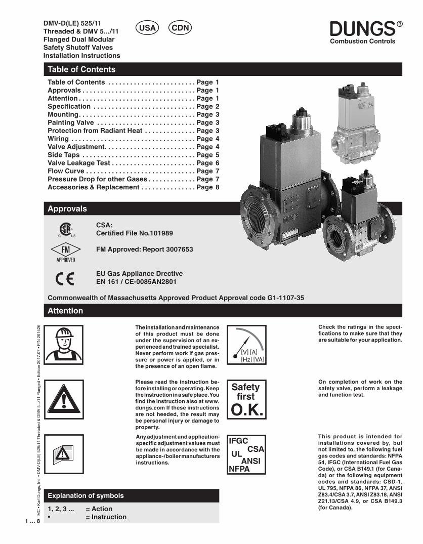
CSA: CertifiedFileNo.101989
FMApproved:Report3007653
EUGasApplianceDrective EN161/CE-0085AN2801
CommonwealthofMassachusettsApprovedProductApprovalcodeG1-1107-35
DMV-D(LE) 525/11 Threaded & DMV 5.../11 Flanged Dual Modular Safety Shutoff ValvesInstallation Instructions
TableofContents
USA CDN
TableofContents . . . . . . . . . . . . . . . . . . . . . . . . Page1Approvals . . . . . . . . . . . . . . . . . . . . . . . . . . . . . . . Page1Attention . . . . . . . . . . . . . . . . . . . . . . . . . . . . . . . . Page1Specification . . . . . . . . . . . . . . . . . . . . . . . . . . . . Page2Mounting. . . . . . . . . . . . . . . . . . . . . . . . . . . . . . . . Page3PaintingValve . . . . . . . . . . . . . . . . . . . . . . . . . . . Page3ProtectionfromRadiantHeat . . . . . . . . . . . . . . Page3Wiring . . . . . . . . . . . . . . . . . . . . . . . . . . . . . . . . . . Page4ValveAdjustment. . . . . . . . . . . . . . . . . . . . . . . . . Page4SideTaps . . . . . . . . . . . . . . . . . . . . . . . . . . . . . . . Page5ValveLeakageTest. . . . . . . . . . . . . . . . . . . . . . . Page6FlowCurve. . . . . . . . . . . . . . . . . . . . . . . . . . . . . . Page7PressureDropforotherGases . . . . . . . . . . . . . Page7Accessories&Replacement. . . . . . . . . . . . . . . Page8
Approvals
1,2,3... =Action • =Instruction
Explanation of symbols
On completion of work on thesafetyvalve,performaleakageandfunctiontest.
Please read the instructionbe-foreinstallingoroperating.Keeptheinstructioninasafeplace.Youfindtheinstructionalsoatwww.dungs.comIftheseinstructionsarenotheeded, the resultmaybepersonalinjuryordamagetoproperty.Anyadjustmentandapplication-specificadjustmentvaluesmustbemadeinaccordancewiththeappliance-/boilermanufacturersinstructions.
Attention
Check the ratings in thespeci-ficationstomakesurethattheyaresuitableforyourapplication.
[V] [A] [Hz] [VA]
Safetyfirst
O.K.IFGC
CSAULANSI
NFPA
This product is intended forinstallations covered by, butnotlimitedto,thefollowingfuelgascodesandstandards:NFPA54,IFGC(InternationalFuelGasCode),orCSAB149.1(forCana-da)or the followingequipmentcodes and standards: CSD-1,UL795,NFPA86,NFPA37,ANSIZ83.4/CSA3.7,ANSIZ83.18,ANSIZ21.13/CSA4.9, orCSAB149.3(forCanada).
Theinstallationandmaintenanceof this product must be doneunderthesupervisionofanex-periencedandtrainedspecialist.Neverperformworkifgaspres-sure or power is applied, or inthepresenceofanopenflame.
3…82…8
MC
• Ka
rl D
ungs
, Inc
. • D
MV-
D(L
E) 5
25/1
1 Th
read
ed &
DM
V 5.
../11
Fla
nged
• Ed
ition
2017
.07
• P/N
261
426
Specification
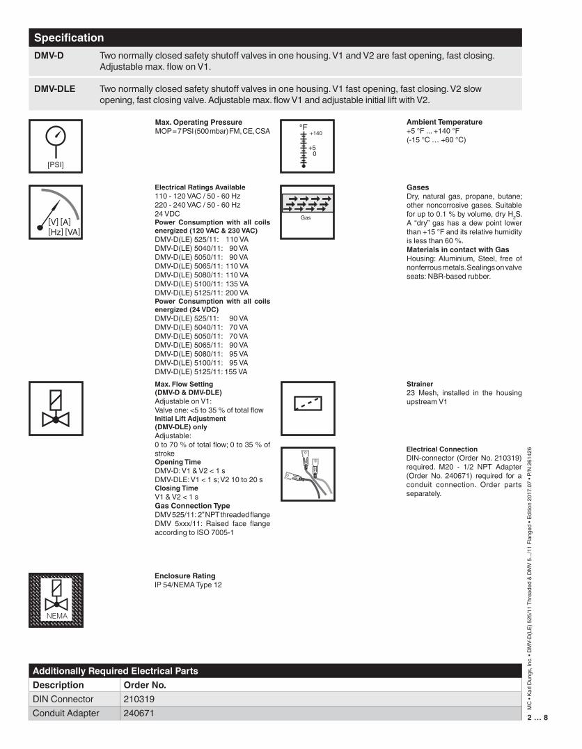
Max.OperatingPressureMOP = 7 PSI (500 mbar) FM, CE, CSA
AmbientTemperature+5 °F ... +140 °F(-15 °C … +60 °C)
GasesDry, natural gas, propane, butane; other noncorrosive gases. Suitable for up to 0.1 % by volume, dry H2S. A “dry” gas has a dew point lower than +15 °F and its relative humidity is less than 60 %. MaterialsincontactwithGasHousing: Aluminium, Steel, free of nonferrous metals. Sealings on valve seats: NBR-based rubber.
ElectricalRatingsAvailable110 - 120 VAC / 50 - 60 Hz220 - 240 VAC / 50 - 60 Hz24 VDCPower Consumptionwith all coilsenergized(120VAC&230VAC)DMV-D(LE) 525/11: 110 VADMV-D(LE) 5040/11: 90 VADMV-D(LE) 5050/11: 90 VADMV-D(LE) 5065/11: 110 VADMV-D(LE) 5080/11: 110 VADMV-D(LE) 5100/11: 135 VADMV-D(LE) 5125/11: 200 VAPower Consumptionwith all coilsenergized(24VDC)DMV-D(LE) 525/11: 90 VADMV-D(LE) 5040/11: 70 VADMV-D(LE) 5050/11: 70 VADMV-D(LE) 5065/11: 90 VADMV-D(LE) 5080/11: 95 VADMV-D(LE) 5100/11: 95 VADMV-D(LE) 5125/11: 155 VA
Strainer23 Mesh, installed in the housing upstream V1
Max.FlowSetting(DMV-D&DMV-DLE)Adjustable on V1: Valve one: <5 to 35 % of total flowInitialLiftAdjustment(DMV-DLE)onlyAdjustable: 0 to 70 % of total flow; 0 to 35 % of strokeOpeningTimeDMV-D: V1 & V2 < 1 sDMV-DLE: V1 < 1 s; V2 10 to 20 sClosingTimeV1 & V2 < 1 sGasConnectionTypeDMV 525/11: 2” NPT threaded flangeDMV 5xxx/11: Raised face flange according to ISO 7005-1
DMV-D Two normally closed safety shutoff valves in one housing. V1 and V2 are fast opening, fast closing. Adjustable max. flow on V1.
DMV-DLE Two normally closed safety shutoff valves in one housing. V1 fast opening, fast closing. V2 slow opening, fast closing valve. Adjustable max. flow V1 and adjustable initial lift with V2.
[PSI]
[V] [A] [Hz] [VA]
Gas
°F
0+5
+140
NEMA
EnclosureRatingIP 54/NEMA Type 12
ElectricalConnectionDIN-connector (Order No. 210319) required. M20 - 1/2 NPT Adapter (Order No. 240671) required for a conduit connection. Order parts separately.
AdditionallyRequiredElectricalPartsDescription OrderNo.DIN Connector 210319Conduit Adapter 240671
3…82…8
MC
• Ka
rl D
ungs
, Inc
. • D
MV-
D(L
E) 5
25/1
1 Th
read
ed &
DM
V 5.
../11
Fla
nged
• Ed
ition
2017
.07
• P/N
261
426
Mounting
PaintingValve
18
19
Chrome S
teel �
Mad
e in G
erman
y
[Ib-in]
• It is not recommended that this valve be painted. Painting covers date codes and other labels that identify this valve.
• If the valve needs to be painted, a paint free of volitile organic componants (VOC’s) must be used. VOC’s can damage
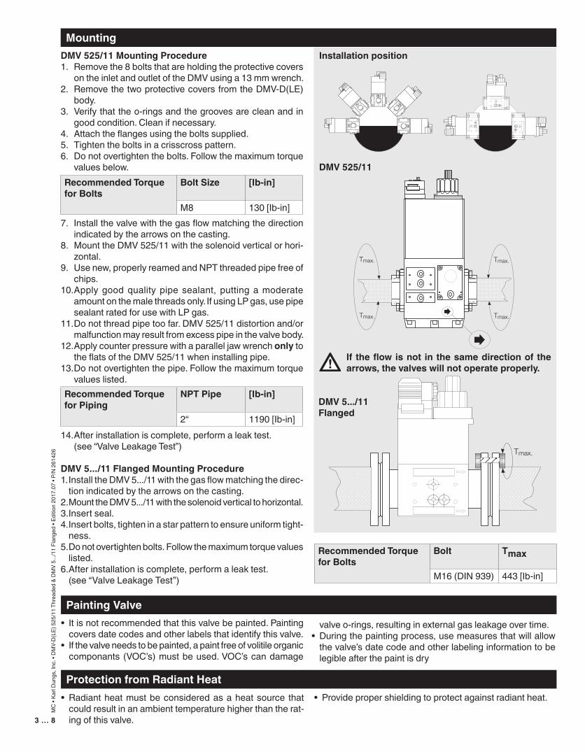
Installationposition
If theflowisnot in thesamedirectionof thearrows,thevalveswillnotoperateproperly.
ProtectionfromRadiantHeat• Radiant heat must be considered as a heat source that
could result in an ambient temperature higher than the rat-ing of this valve.
• Provide proper shielding to protect against radiant heat.
DMV525/11MountingProcedure1. Remove the 8 bolts that are holding the protective covers
on the inlet and outlet of the DMV using a 13 mm wrench.2. Remove the two protective covers from the DMV-D(LE)
body.3. Verify that the o-rings and the grooves are clean and in
good condition. Clean if necessary.4. Attach the flanges using the bolts supplied.5. Tighten the bolts in a crisscross pattern.6. Do not overtighten the bolts. Follow the maximum torque
values below.
7. Install the valve with the gas flow matching the direction indicated by the arrows on the casting.
8. Mount the DMV 525/11 with the solenoid vertical or hori-zontal.
9. Use new, properly reamed and NPT threaded pipe free of chips.
10. Apply good quality pipe sealant, putting a moderate amount on the male threads only. If using LP gas, use pipe sealant rated for use with LP gas.
11. Do not thread pipe too far. DMV 525/11 distortion and/or malfunction may result from excess pipe in the valve body.
12. Apply counter pressure with a parallel jaw wrench only to the flats of the DMV 525/11 when installing pipe.
13. Do not overtighten the pipe. Follow the maximum torque values listed.
14. After installation is complete, perform a leak test. (see “Valve Leakage Test”)
DMV5.../11FlangedMountingProcedure1. Install the DMV 5.../11 with the gas flow matching the direc-
tion indicated by the arrows on the casting.2. Mount the DMV 5.../11 with the solenoid vertical to horizontal.3. Insert seal.4. Insert bolts, tighten in a star pattern to ensure uniform tight-
ness.5. Do not overtighten bolts. Follow the maximum torque values
listed. 6. After installation is complete, perform a leak test. (see “Valve Leakage Test”)
valve o-rings, resulting in external gas leakage over time.• During the painting process, use measures that will allow
the valve’s date code and other labeling information to be legible after the paint is dry
RecommendedTorqueforBolts
Bolt Tmax
M16 (DIN 939) 443 [Ib-in]
RecommendedTorqueforBolts
BoltSize [Ib-in]
M8 130 [Ib-in]
RecommendedTorqueforPiping
NPTPipe [Ib-in]
2“ 1190 [Ib-in]
DMV525/11
DMV5.../11Flanged
5…84…8
MC
• Ka
rl D
ungs
, Inc
. • D
MV-
D(L
E) 5
25/1
1 Th
read
ed &
DM
V 5.
../11
Fla
nged
• Ed
ition
2017
.07
• P/N
261
426
ValveAdjustment
Wiring• Disconnect all power to the valves before wiring to prevent
electrical shock and equipment damage.• Do not exceed the electrical ratings given in the specifica-
tions and on the valve.• Attach a flexible 1/2” NPT conduit to the DIN connector.• Route the wires through the conduit and the DIN connector.• Use 14 or 16 gauge wire for at least 75 °C (167 °F).• Connect the wiring to the appropriate screw terminals in
the DIN connector.• Plug the DIN connector into the AMP terminals on the valve.
Fasten the DIN connector with the screw supplied.
Allwiringmust complywith local electricalcodes,ordinancesandregulations.
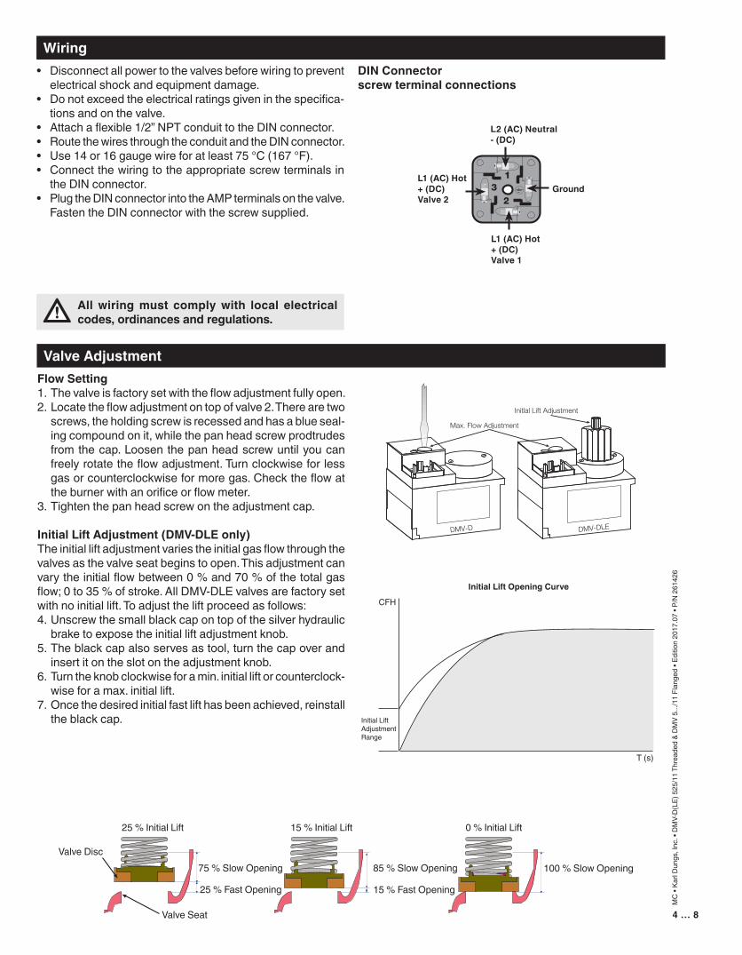
FlowSetting1. The valve is factory set with the flow adjustment fully open.2. Locate the flow adjustment on top of valve 2. There are two
screws, the holding screw is recessed and has a blue seal-ing compound on it, while the pan head screw prodtrudes from the cap. Loosen the pan head screw until you can freely rotate the flow adjustment. Turn clockwise for less gas or counterclockwise for more gas. Check the flow at the burner with an orifice or flow meter.
3. Tighten the pan head screw on the adjustment cap.
InitialLiftAdjustment(DMV-DLEonly)The initial lift adjustment varies the initial gas flow through the valves as the valve seat begins to open. This adjustment can vary the initial flow between 0 % and 70 % of the total gas flow; 0 to 35 % of stroke. All DMV-DLE valves are factory set with no initial lift. To adjust the lift proceed as follows:4. Unscrew the small black cap on top of the silver hydraulic
brake to expose the initial lift adjustment knob.5. The black cap also serves as tool, turn the cap over and
insert it on the slot on the adjustment knob.6. Turn the knob clockwise for a min. initial lift or counterclock-
wise for a max. initial lift.7. Once the desired initial fast lift has been achieved, reinstall
the black cap.
25 % Initial Lift 15 % Initial Lift 0 % Initial Lift
75 % Slow OpeningValve Disc
Valve Seat
25 % Fast Opening 15 % Fast Opening
85 % Slow Opening 100 % Slow Opening
Initial Lift Opening Curve
CFH
Initial LiftAdjustment Range
T (s)
DINConnectorscrewterminalconnections
L2(AC)Neutral-(DC)
Ground
L1(AC)Hot+(DC)Valve1
L1(AC)Hot+(DC)Valve2
5…84…8
MC
• Ka
rl D
ungs
, Inc
. • D
MV-
D(L
E) 5
25/1
1 Th
read
ed &
DM
V 5.
../11
Fla
nged
• Ed
ition
2017
.07
• P/N
261
426
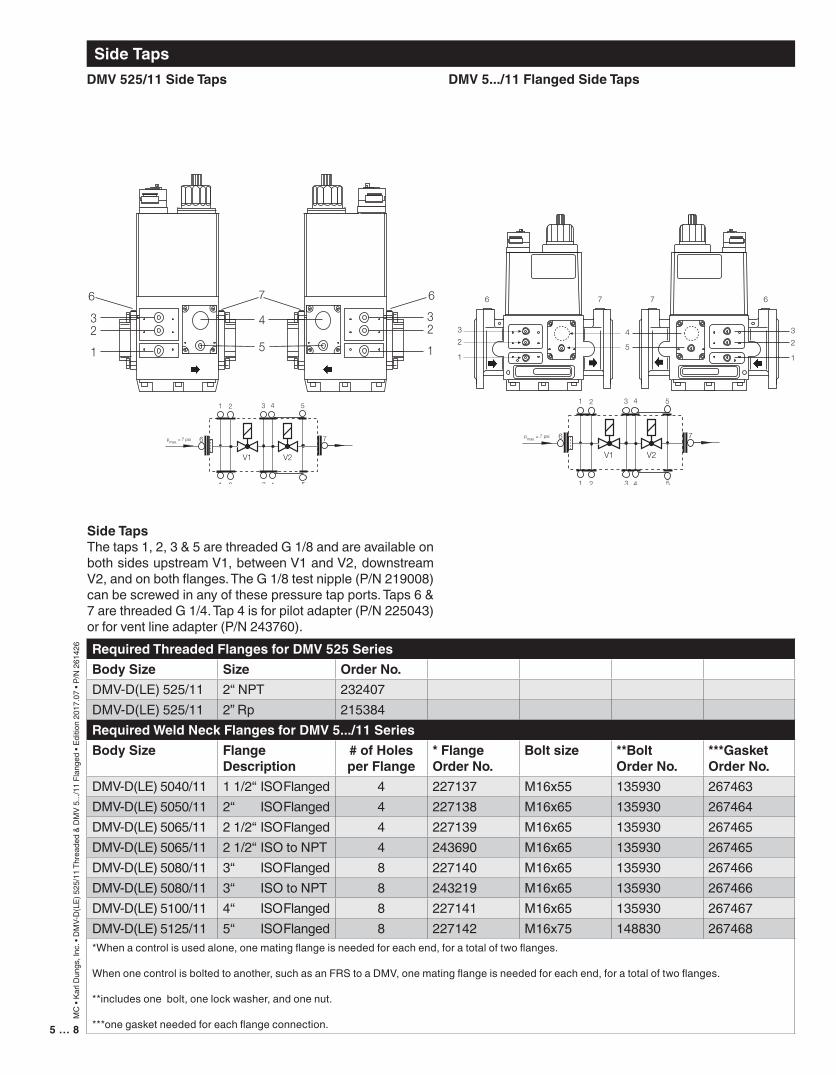
SideTapsDMV525/11SideTaps
6 7
6 7 6
6 7
DMV5.../11FlangedSideTaps
RequiredThreadedFlangesforDMV525SeriesBodySize Size OrderNo.DMV-D(LE) 525/11 2“ NPT 232407DMV-D(LE) 525/11 2” Rp 215384RequiredWeldNeckFlangesforDMV5.../11SeriesBodySize Flange
Description#ofHolesperFlange
*FlangeOrderNo.
Boltsize **BoltOrderNo.
***GasketOrderNo.
DMV-D(LE) 5040/11 1 1/2“ ISO Flanged 4 227137 M16x55 135930 267463DMV-D(LE) 5050/11 2“ ISO Flanged 4 227138 M16x65 135930 267464DMV-D(LE) 5065/11 2 1/2“ ISO Flanged 4 227139 M16x65 135930 267465DMV-D(LE) 5065/11 2 1/2“ ISO to NPT 4 243690 M16x65 135930 267465DMV-D(LE) 5080/11 3“ ISO Flanged 8 227140 M16x65 135930 267466DMV-D(LE) 5080/11 3“ ISO to NPT 8 243219 M16x65 135930 267466DMV-D(LE) 5100/11 4“ ISO Flanged 8 227141 M16x65 135930 267467DMV-D(LE) 5125/11 5“ ISO Flanged 8 227142 M16x75 148830 267468*When a control is used alone, one mating flange is needed for each end, for a total of two flanges.
When one control is bolted to another, such as an FRS to a DMV, one mating flange is needed for each end, for a total of two flanges.
**includes one bolt, one lock washer, and one nut.
***one gasket needed for each flange connection.
SideTapsThe taps 1, 2, 3 & 5 are threaded G 1/8 and are available on both sides upstream V1, between V1 and V2, downstream V2, and on both flanges. The G 1/8 test nipple (P/N 219008) can be screwed in any of these pressure tap ports. Taps 6 & 7 are threaded G 1/4. Tap 4 is for pilot adapter (P/N 225043) or for vent line adapter (P/N 243760).
7…86…8
MC
• Ka
rl D
ungs
, Inc
. • D
MV-
D(L
E) 5
25/1
1 Th
read
ed &
DM
V 5.
../11
Fla
nged
• Ed
ition
2017
.07
• P/N
261
426
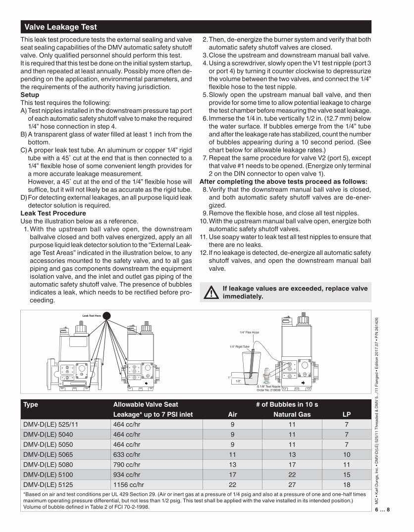
ValveLeakageTest
Type AllowableValveSeat #ofBubblesin10sLeakage*upto7PSIinlet Air NaturalGas LP
DMV-D(LE) 525/11 464 cc/hr 9 11 7DMV-D(LE) 5040 464 cc/hr 9 11 7DMV-D(LE) 5050 464 cc/hr 9 11 7DMV-D(LE) 5065 633 cc/hr 11 13 10DMV-D(LE) 5080 790 cc/hr 13 17 11DMV-D(LE) 5100 934 cc/hr 17 22 15DMV-D(LE) 5125 1156 cc/hr 22 27 18*Based on air and test conditions per UL 429 Section 29. (Air or inert gas at a pressure of 1/4 psig and also at a pressure of one and one-half times maximum operating pressure differential, but not less than 1/2 psig. This test shall be applied with the valve installed in its intended position.)Volume of bubble defined in Table 2 of FCI 70-2-1998.
Ifleakagevaluesareexceeded,replacevalveimmediately.
This leak test procedure tests the external sealing and valve seat sealing capabilities of the DMV automatic safety shutoff valve. Only qualified personnel should perform this test.It is required that this test be done on the initial system startup, and then repeated at least annually. Possibly more often de-pending on the application, environmental parameters, and the requirements of the authority having jurisdiction.SetupThis test requires the following:A) Test nipples installed in the downstream pressure tap port
of each automatic safety shutoff valve to make the required 1/4” hose connection in step 4.
B) A transparent glass of water filled at least 1 inch from the bottom.
C) A proper leak test tube. An aluminum or copper 1/4” rigid tube with a 45˚ cut at the end that is then connected to a 1/4” flexible hose of some convenient length provides for a more accurate leakage measurement.
However, a 45˚ cut at the end of the 1/4” flexible hose will suffice, but it will not likely be as accurate as the rigid tube.
D) For detecting external leakages, an all purpose liquid leak detector solution is required.
LeakTestProcedureUse the illustration below as a reference. 1. With the upstream ball valve open, the downstream
ballvalve closed and both valves energized, apply an all purpose liquid leak detector solution to the “External Leak-age Test Areas” indicated in the illustration below, to any accessories mounted to the safety valve, and to all gas piping and gas components downstream the equipment isolation valve, and the inlet and outlet gas piping of the automatic safety shutoff valve. The presence of bubbles indicates a leak, which needs to be rectified before pro-ceeding.
2. Then, de-energize the burner system and verify that both automatic safety shutoff valves are closed.
3. Close the upstream and downstream manual ball valve. 4. Using a screwdriver, slowly open the V1 test nipple (port 3
or port 4) by turning it counter clockwise to depressurize the volume between the two valves, and connect the 1/4” flexible hose to the test nipple.
5. Slowly open the upstream manual ball valve, and then provide for some time to allow potential leakage to charge the test chamber before measuring the valve seat leakage.
6. Immerse the 1/4 in. tube vertically 1/2 in. (12.7 mm) below the water surface. If bubbles emerge from the 1/4” tube and after the leakage rate has stabilized, count the number of bubbles appearing during a 10 second period. (See chart below for allowable leakage rates.)
7. Repeat the same procedure for valve V2 (port 5), except that valve #1 needs to be opened. (Energize only terminal 2 on the DIN connector to open valve 1).
Aftercompletingtheabovetestsproceedasfollows: 8. Verify that the downstream manual ball valve is closed,
and both automatic safety shutoff valves are de-ener-gized.
9. Remove the flexible hose, and close all test nipples. 10. With the upstream manual ball valve open, energize both
automatic safety shutoff valves.11. Use soapy water to leak test all test nipples to ensure that
there are no leaks.12. If no leakage is detected, de-energize all automatic safety
shutoff valves, and open the downstream manual ball valve.
Leak Test Here
G 1/8“ Test NippleOrder No. 219008
1/4“ Rigid Tube
1/4“ Flex Hose
1“1/2“
7…86…8
MC
• Ka
rl D
ungs
, Inc
. • D
MV-
D(L
E) 5
25/1
1 Th
read
ed &
DM
V 5.
../11
Fla
nged
• Ed
ition
2017
.07
• P/N
261
426
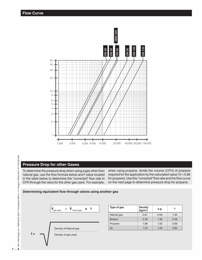
FlowCurve
PressureDropforotherGasesTo determine the pressure drop when using a gas other than natural gas, use the flow formula below and f value located in the table below to determine the “corrected” flow rate in CFH through the valve for the other gas used. For example,
when using propane, divide the volume (CFH) of propane required for the application by the calculated value f (f = 0.66 for propane). Use this “corrected” flow rate and the flow curve on the next page to determine pressure drop for propane.
Density of Natural gas
Density of gas usedf=
Typeofgas Density[kg/m3] s.g. f
Natural gas 0.81 0.65 1.00Butane 2.39 1.95 0.58Propane 1.86 1.50 0.66Air 1.24 1.00 0.80
Determiningequivalentflowthroughvalvesusinganothergas
Vgas used = V Natural gas x f° °
40,000 60,000
8 … 8
MC
• Ka
rl D
ungs
, Inc
. • D
MV-
D(L
E) 5
25/1
1 Th
read
ed &
DM
V 5.
../11
Fla
nged
• Ed
ition
2017
.07
• P/N
261
426
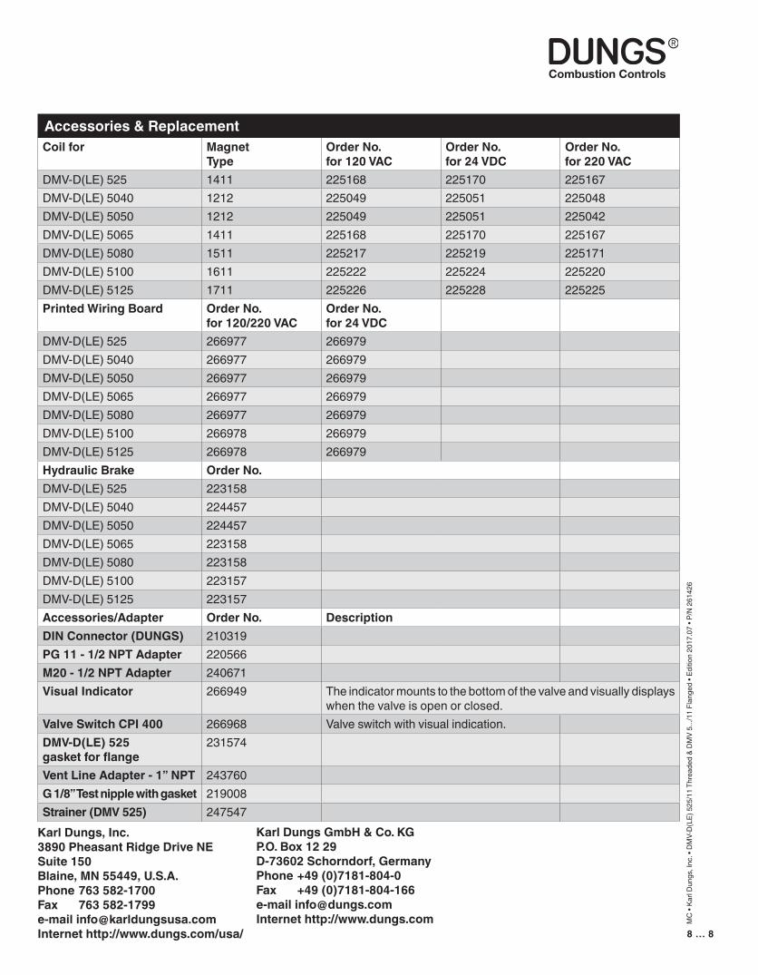
Accessories&Replacement
KarlDungsGmbH&Co.KGP.O.Box1229D-73602Schorndorf,GermanyPhone+49(0)7181-804-0Fax +49(0)[email protected]://www.dungs.com
KarlDungs,Inc.3890PheasantRidgeDriveNESuite150Blaine,MN55449,U.S.A.Phone763582-1700Fax [email protected]://www.dungs.com/usa/
Coilfor MagnetType
OrderNo.for120VAC
OrderNo.for24VDC
OrderNo.for220VAC
DMV-D(LE) 525 1411 225168 225170 225167DMV-D(LE) 5040 1212 225049 225051 225048DMV-D(LE) 5050 1212 225049 225051 225042DMV-D(LE) 5065 1411 225168 225170 225167DMV-D(LE) 5080 1511 225217 225219 225171DMV-D(LE) 5100 1611 225222 225224 225220DMV-D(LE) 5125 1711 225226 225228 225225PrintedWiringBoard OrderNo.
for120/220VACOrderNo.for24VDC
DMV-D(LE) 525 266977 266979DMV-D(LE) 5040 266977 266979DMV-D(LE) 5050 266977 266979DMV-D(LE) 5065 266977 266979DMV-D(LE) 5080 266977 266979DMV-D(LE) 5100 266978 266979DMV-D(LE) 5125 266978 266979HydraulicBrake OrderNo.DMV-D(LE) 525 223158DMV-D(LE) 5040 224457DMV-D(LE) 5050 224457DMV-D(LE) 5065 223158DMV-D(LE) 5080 223158DMV-D(LE) 5100 223157DMV-D(LE) 5125 223157Accessories/Adapter OrderNo. DescriptionDINConnector(DUNGS) 210319PG11-1/2NPTAdapter 220566M20-1/2NPTAdapter 240671VisualIndicator 266949 The indicator mounts to the bottom of the valve and visually displays
when the valve is open or closed.ValveSwitchCPI400 266968 Valve switch with visual indication.DMV-D(LE)525gasketforflange
231574
VentLineAdapter-1”NPT 243760G1/8”Testnipplewithgasket 219008Strainer(DMV525) 247547