Embed Size (px)
Citation preview
DKM-430 User Manual Rev_02 Firmware V-1.8
DKM-430
MULTIPLE NETWORK
ANALYSER
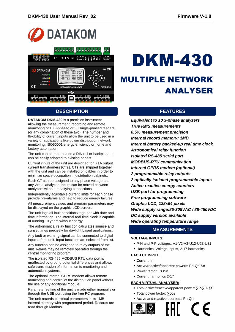
DATAKOM DKM-430 is a precision instrument
allowing the measurement, recording and remote monitoring of 10 3-phased or 30 single-phased feeders (or any combination of these two). The number and flexibility of current inputs allow the unit to be used in a variety of applications like power distribution network monitoring, ISO50001 energy efficiency or home and factory automation.
The unit can be mounted on a DIN rail or backplane. It can be easily adapted to existing panels.
Current inputs of the unit are designed for 0.1A output current transformers (CTs). CTs are shipped together with the unit and can be installed on cables in order to minimize space occupation in distribution cabinets.
Each CT can be assigned to any phase voltage and any virtual analyzer. Inputs can be moved between analyzers without modifying connections.
Independently adjustable current limits for each phase provide pre-alarms and help to reduce energy failures.
All measurement values and program parameters may be displayed on the graphic LCD screen.
The unit logs all fault conditions together with date and time information. The internal real time clock is capable of running 10 years without energy.
The astronomical relay function calculates sunrise and sunset times precisely for daylight based applications.
Any fault or warning signal can be connected to digital inputs of the unit. Input functions are selected from list.
Any function can be assigned to relay outputs of the unit. Relays may be remotely operated through the central monitoring program.
The isolated RS-485 MODBUS RTU data port is unaffected by ground potential differences and allows safe transmission of information to monitoring and automation systems.
The optional internal GPRS modem allows remote monitoring and control of the distribution panel without the use of any additional module.
Parameter setting of the unit is made either manually or through the USB port using the free PC program.
The unit records electrical parameters in its 1MB internal memory with programmed period. Records are read through Modbus.
Equivalent to 10 3-phase analyzers
True RMS measurements
0.5% measurement precision
Internal record memory: 1MB
Internal battery backed-up real time clock
Astronomical relay function
Isolated RS-485 serial port
MODBUS-RTU communication
Internal GPRS modem (optional)
2 programmable relay outputs
2 optically isolated programmable inputs
Active-reactive energy counters
USB port for programming
Free programming software
Graphic LCD, 128x64 pixels
Wide supply range:85-305VAC / 88-450VDC
DC supply version available
Wide operating temperature range
VOLTAGE INPUTS:
P-N and P-P voltages: V1-V2-V3-U12-U23-U31
Harmonics: Voltage inputs, 2-17 harmonics
EACH CT INPUT:
Current: In
Active/reactive/apparent powers: Pn-Qn-Sn
Power factor: COSn
Current harmonics 2-17
EACH VIRTUAL ANALYSER:
Total active/reactive/apparent power: ∑P-∑Q-∑S
Total power factor: ∑cos
Active and reactive counters: Pn-Qn
FEATURES
MEASUREMENTS
DESCRIPTION
DKM-430 User Manual Rev_02 Firmware V-1.8
K92D01-EN - 2 -
Any unauthorized use or copying of the contents or any part of this document is prohibited.
This document describes minimum requirements and necessary steps for the successful installation of the DKM-430 family units.
Follow carefully advices given in the document. These are often good practices for the installation which reduce future issues.
For all technical queries please contact Datakom at below e-mail address:
If additional information to this manual is required, please contact the manufacturer directly at below e-mail address:
Please provide following information in order to get answers to any question:
- Device model name (see the back panel of the unit), - Complete serial number (see the back panel of the unit), - Firmware version (read from the display screen), - Measuring-circuit voltage and power supply voltage, - Precise description of the query.
FILENAME DESCRIPTION
500-Rainbow Installation Rainbow Plus D-500 D-700 Installation Guide
500-Rainbow Usage Rainbow Plus D-500 D-700 Usage Guide
500-Rainbow Scada Installation Rainbow Scada Installation Guide
500-Rainbow Scada Usage Rainbow Scada Usage Guide
QUERRIES
RELATED DOCUMENTS
ABOUT THIS DOCUMENT
COPYRIGHT NOTICE
DKM-430 User Manual Rev_02 Firmware V-1.8
K92D01-EN - 3 -
REVISION DATE AUTHOR DESCRIPTION
01 15.06.2015 MH First edition
02 15.02.2017 ME Modbus addresses updated
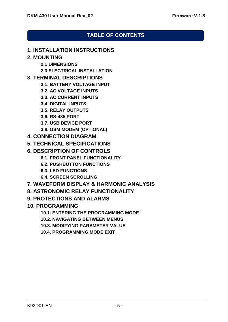
CAUTION: Potential risk of injury or death.
WARNING: Potential risk of malfunction or material damage.
ATTENTION: Useful hints for the understanding of device operation.
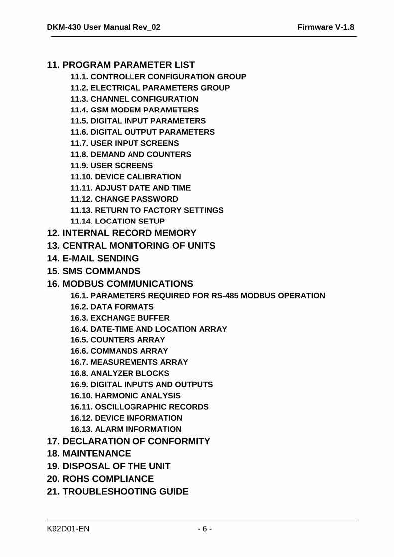
The D-500 family units are available in various options and peripheral features. Please use below information for ordering the correct version:
DKM-430 -M -T -00
REVISION HISTORY
TERMINOLOGY
ORDERING CODES
Family Code
With Internal GSM-GPRS Modem
With Conformal Coating
Variant 00: standard unit 01...99: customer specific products

DKM-430 User Manual Rev_02 Firmware V-1.8
K92D01-EN - 4 -
Electrical equipment should be installed only by qualified specialist. No responsibility is assured by the manufacturer or any of its subsidiaries for any consequences resulting from the non-compliance to these instructions.
Check the unit for cracks and damages due to transportation. Do not install damaged equipment.
Do not open the unit. There are no serviceable parts inside.
Fuses must be connected to the power supply and phase voltage inputs, in close proximity of the unit.
Fuses must be of fast type (FF) with a maximum rating of 6A.
Disconnect all power before working on equipment.
When the unit is connected to the network do not touch terminals.
Short circuit terminals of unused current transformers.
Any electrical parameter applied to the device must be in the range specified in the user manual. Although the unit is designed with a wide safety margin, over-range parameters may reduce lifetime, alter operational precision or even damage the unit.
Do not try to clean the device with solvent or the like. Only clean with a dump cloth.
Verify correct terminal connections before applying power.
Only for panel base mounting.
SAFETY NOTICE
Failure to follow below instructions
will result in death or serious injury
Current measurement is made with CTs provided together with the module.
Do not apply direct connection, do not use 1A/5A current transformers.
DKM-430 User Manual Rev_02 Firmware V-1.8
K92D01-EN - 5 -
1. INSTALLATION INSTRUCTIONS
2. MOUNTING
2.1 DIMENSIONS
2.3 ELECTRICAL INSTALLATION
3. TERMINAL DESCRIPTIONS
3.1. BATTERY VOLTAGE INPUT
3.2. AC VOLTAGE INPUTS
3.3. AC CURRENT INPUTS
3.4. DIGITAL INPUTS
3.5. RELAY OUTPUTS
3.6. RS-485 PORT
3.7. USB DEVICE PORT
3.8. GSM MODEM (OPTIONAL)
4. CONNECTION DIAGRAM
5. TECHNICAL SPECIFICATIONS
6. DESCRIPTION OF CONTROLS
6.1. FRONT PANEL FUNCTIONALITY
6.2. PUSHBUTTON FUNCTIONS
6.3. LED FUNCTIONS
6.4. SCREEN SCROLLING
7. WAVEFORM DISPLAY & HARMONIC ANALYSIS
8. ASTRONOMIC RELAY FUNCTIONALITY
9. PROTECTIONS AND ALARMS
10. PROGRAMMING
10.1. ENTERING THE PROGRAMMING MODE
10.2. NAVIGATING BETWEEN MENUS
10.3. MODIFYING PARAMETER VALUE
10.4. PROGRAMMING MODE EXIT
TABLE OF CONTENTS
DKM-430 User Manual Rev_02 Firmware V-1.8
K92D01-EN - 6 -
11. PROGRAM PARAMETER LIST
11.1. CONTROLLER CONFIGURATION GROUP
11.2. ELECTRICAL PARAMETERS GROUP
11.3. CHANNEL CONFIGURATION
11.4. GSM MODEM PARAMETERS
11.5. DIGITAL INPUT PARAMETERS
11.6. DIGITAL OUTPUT PARAMETERS
11.7. USER INPUT SCREENS
11.8. DEMAND AND COUNTERS
11.9. USER SCREENS
11.10. DEVICE CALIBRATION
11.11. ADJUST DATE AND TIME
11.12. CHANGE PASSWORD
11.13. RETURN TO FACTORY SETTINGS
11.14. LOCATION SETUP
12. INTERNAL RECORD MEMORY
13. CENTRAL MONITORING OF UNITS
14. E-MAIL SENDING
15. SMS COMMANDS
16. MODBUS COMMUNICATIONS
16.1. PARAMETERS REQUIRED FOR RS-485 MODBUS OPERATION
16.2. DATA FORMATS
16.3. EXCHANGE BUFFER
16.4. DATE-TIME AND LOCATION ARRAY
16.5. COUNTERS ARRAY
16.6. COMMANDS ARRAY
16.7. MEASUREMENTS ARRAY
16.8. ANALYZER BLOCKS
16.9. DIGITAL INPUTS AND OUTPUTS
16.10. HARMONIC ANALYSIS
16.11. OSCILLOGRAPHIC RECORDS
16.12. DEVICE INFORMATION
16.13. ALARM INFORMATION
17. DECLARATION OF CONFORMITY
18. MAINTENANCE
19. DISPOSAL OF THE UNIT
20. ROHS COMPLIANCE
21. TROUBLESHOOTING GUIDE
DKM-430 User Manual Rev_02 Firmware V-1.8
K92D01-EN - 7 -
Before installation:
Read the user manual carefully, determine the correct connection diagram.
Install to the panel base or DIN rail. In order to install to panel base, pull mounting tabs at corners.
Make electrical connections with plugs removed from sockets, then place plugs to their sockets.
Be sure that adequate cooling is provided.
Be sure that the temperature of the environment will not exceed the maximum operating temperature in any case.
Be sure that the unit is not subject to water spill.
Below conditions may damage the device:
Incorrect connections.
Incorrect power supply voltage.
Voltage at measuring terminals beyond specified range.
Voltage applied to digital inputs over specified range.
Current at measuring terminals beyond specified range.
Overload or short circuit at relay outputs
Connecting or removing data terminals when the unit is powered-up.
High voltage applied to communication ports.
Ground potential differences at non-isolated communication ports.
Excessive vibration, direct installation on vibrating parts.
Below conditions may cause abnormal operation:
Power supply voltage below minimum acceptable level.
Power supply frequency out of specified limits
Phase order of voltage inputs not correct.
Current transformers not matching related phases.
Current transformer polarity incorrect.
Missing grounding.
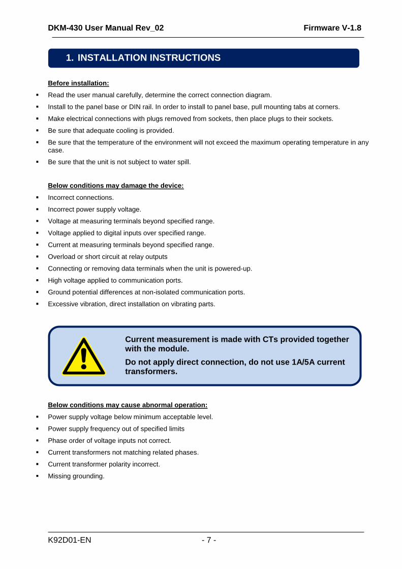
Current measurement is made with CTs provided together with the module.
Do not apply direct connection, do not use 1A/5A current transformers.
1. INSTALLATION INSTRUCTIONS
DKM-430 User Manual Rev_02 Firmware V-1.8
K92D01-EN - 8 -
Dimensions: 158x90x60mm (6.22”x3.55”x2.36”) Installation: Panel base or DIN rail Weight: 350g (0.77 lb)
Although the unit is protected against electromagnetic disturbance, excessive disturbance can affect the operation, measurement precision and data communication quality.
ALWAYS remove plug connectors when inserting wires with a screwdriver.
Fuses must be connected to the power supply and phase voltage inputs, in close proximity of the unit.
Fuses must be of fast type (FF) with a maximum rating of 6A.
Use cables of appropriate temperature range.
Use adequate cable section, at least 0.75mm2 (AWG18).
Follow national rules for electrical installation.
Current transformers must have 0.1A output.
2.1. DIMENSIONS
Current measurement is made with CTs provided together with the module.
Do not apply direct connection, do not use 1A/5A current transformers.
Do not install the unit close to high electromagnetic noise emitting devices like contactors, high current busbars, switchmode power supplies and the like.
2.2. ELECTRICAL INSTALLATION
2. MOUNTING
DKM-430 User Manual Rev_02 Firmware V-1.8
K92D01-EN - 9 -
Supply voltage: AC SUPPLY VERSIONS: 85-305VAC, 45-65Hz, 88-450VDC
DC SUPPLY VERSIONS: 19-150VDC
Reverse voltage: Non polarized inputs, works in both polarizations.
Maximum input power: 6W
Typical operating current: 250mA @ 12VDC. (all options passive, digital outputs open)
125mA @ 24VDC. (all options passive, digital outputs open)
Maximum operating current:
30mA @ 230VAC. (all features active, digital outputs open)
60mA @ 110VDC. (all features active, digital outputs open)
Measurement method: True RMS
Sampling rate: 2048 Hz
Harmonic analysis: up to 17th harmonic
Input voltage range: 5 to 300 VAC (phase-neutral)
Measurement range: 0 to 330VAC ph-N (0 to 570VAC ph-ph)
Input impedance: 4.5M-ohms
Display resolution: 0.1VDC
Accuracy: 0.5% + 1 digit @ 230VAC ph-N (±2VAC ph-N)
0.5% + 1 digit @ 400VAC ph-ph (±3VAC ph-ph)
Frequency range: 45 to 65 Hz
Frequency display resolution:
0.01 Hz
Frequency accuracy: 0.2% + 1 digit (±0.1 Hz @ 50Hz)
3.1. BATTERY VOLTAGE INPUT
3. TERMINAL DESCRIPTIONS
3.2. AC VOLTAGE INPUTS
DKM-430 User Manual Rev_02 Firmware V-1.8
K92D01-EN - 10 -
Measurement method: True RMS
Sampling rate: 2048 Hz
Harmonic analysis: up to 17th harmonic
CT secondary rating: 100mA
Measurement range: 5/0.1 to 5000/0.1A minimum
Input impedance: 1 ohm
Burden: 10 mW
Maximum continuous current:
500mA
Measurement range: 0.5 to 120mAA
Display resolution: 0.1A
Accuracy: 0.5% + 1 digit @ 100mA
SELECTING THE CT ACCURACY CLASS:
The CT accuracy class should be selected in accordance with the required measurement precision. The accuracy class of the Datakom controller is 0.5%. Thus 0.5% class CTs are advised for the best result.
3.3. AC CURRENT INPUTS
DKM-430 User Manual Rev_02 Firmware V-1.8
K92D01-EN - 11 -
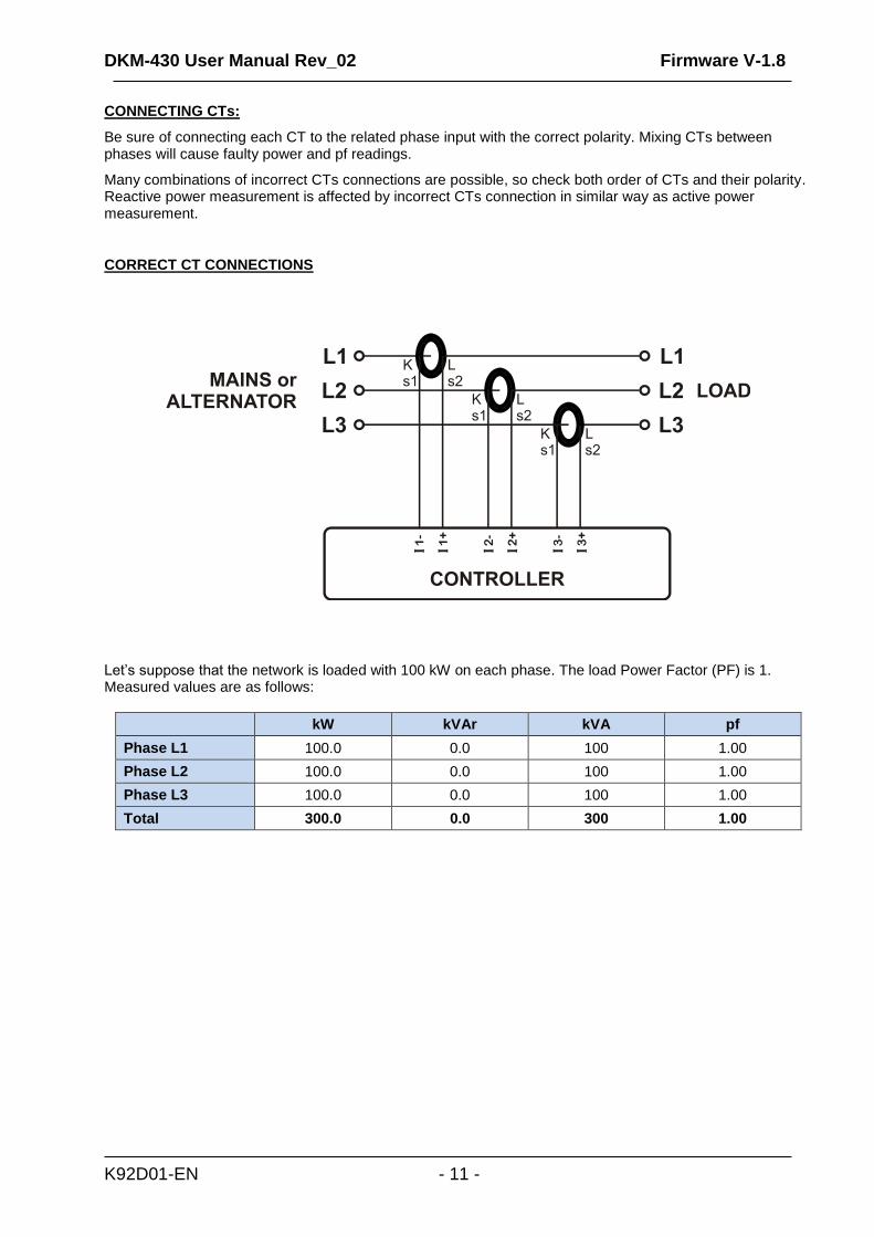
CONNECTING CTs:
Be sure of connecting each CT to the related phase input with the correct polarity. Mixing CTs between phases will cause faulty power and pf readings.
Many combinations of incorrect CTs connections are possible, so check both order of CTs and their polarity. Reactive power measurement is affected by incorrect CTs connection in similar way as active power measurement.
CORRECT CT CONNECTIONS
Let’s suppose that the network is loaded with 100 kW on each phase. The load Power Factor (PF) is 1. Measured values are as follows:
kW kVAr kVA pf
Phase L1 100.0 0.0 100 1.00
Phase L2 100.0 0.0 100 1.00
Phase L3 100.0 0.0 100 1.00
Total 300.0 0.0 300 1.00
DKM-430 User Manual Rev_02 Firmware V-1.8
K92D01-EN - 12 -
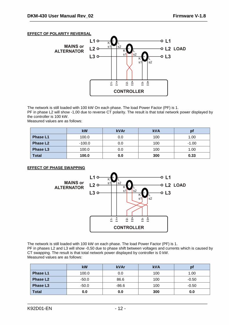
EFFECT OF POLARITY REVERSAL
The network is still loaded with 100 kW On each phase. The load Power Factor (PF) is 1. PF in phase L2 will show -1,00 due to reverse CT polarity. The result is that total network power displayed by the controller is 100 kW. Measured values are as follows:
kW kVAr kVA pf
Phase L1 100.0 0.0 100 1.00
Phase L2 -100.0 0.0 100 -1.00
Phase L3 100.0 0.0 100 1.00
Total 100.0 0.0 300 0.33
EFFECT OF PHASE SWAPPING
The network is still loaded with 100 kW on each phase. The load Power Factor (PF) is 1. PF in phases L2 and L3 will show -0,50 due to phase shift between voltages and currents which is caused by CT swapping. The result is that total network power displayed by controller is 0 kW. Measured values are as follows:
kW kVAr kVA pf
Phase L1 100.0 0.0 100 1.00
Phase L2 -50.0 86.6 100 -0.50
Phase L3 -50.0 -86.6 100 -0.50
Total 0.0 0.0 300 0.0
DKM-430 User Manual Rev_02 Firmware V-1.8
K92D01-EN - 13 -
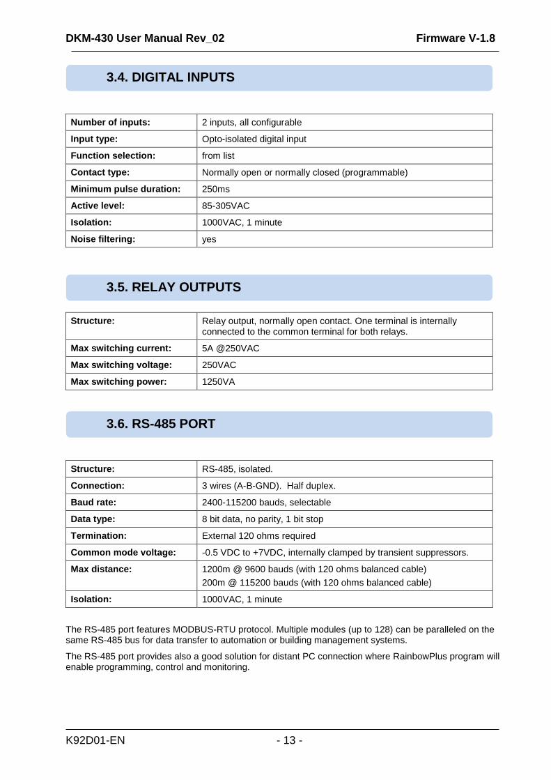
Number of inputs: 2 inputs, all configurable
Input type: Opto-isolated digital input
Function selection: from list
Contact type: Normally open or normally closed (programmable)
Minimum pulse duration: 250ms
Active level: 85-305VAC
Isolation: 1000VAC, 1 minute
Noise filtering: yes
Structure: Relay output, normally open contact. One terminal is internally connected to the common terminal for both relays.
Max switching current: 5A @250VAC
Max switching voltage: 250VAC
Max switching power: 1250VA
Structure: RS-485, isolated.
Connection: 3 wires (A-B-GND). Half duplex.
Baud rate: 2400-115200 bauds, selectable
Data type: 8 bit data, no parity, 1 bit stop
Termination: External 120 ohms required
Common mode voltage: -0.5 VDC to +7VDC, internally clamped by transient suppressors.
Max distance: 1200m @ 9600 bauds (with 120 ohms balanced cable)
200m @ 115200 bauds (with 120 ohms balanced cable)
Isolation: 1000VAC, 1 minute
The RS-485 port features MODBUS-RTU protocol. Multiple modules (up to 128) can be paralleled on the same RS-485 bus for data transfer to automation or building management systems.
The RS-485 port provides also a good solution for distant PC connection where RainbowPlus program will enable programming, control and monitoring.
3.5. RELAY OUTPUTS
3.6. RS-485 PORT
3.4. DIGITAL INPUTS
DKM-430 User Manual Rev_02 Firmware V-1.8
K92D01-EN - 14 -
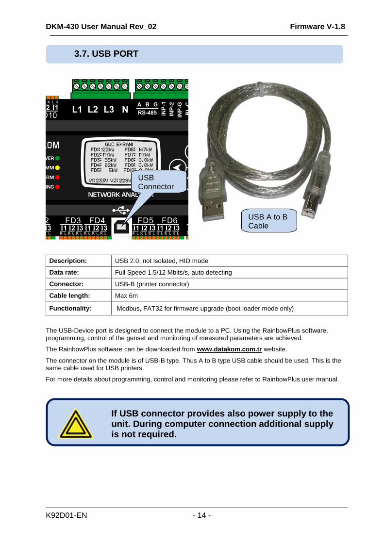
Description: USB 2.0, not isolated, HID mode
Data rate: Full Speed 1.5/12 Mbits/s, auto detecting
Connector: USB-B (printer connector)
Cable length: Max 6m
Functionality: Modbus, FAT32 for firmware upgrade (boot loader mode only)
The USB-Device port is designed to connect the module to a PC. Using the RainbowPlus software, programming, control of the genset and monitoring of measured parameters are achieved.
The RainbowPlus software can be downloaded from www.datakom.com.tr website.
The connector on the module is of USB-B type. Thus A to B type USB cable should be used. This is the same cable used for USB printers.
For more details about programming, control and monitoring please refer to RainbowPlus user manual.
If USB connector provides also power supply to the unit. During computer connection additional supply is not required.
3.7. USB PORT
USB Connector
USB A to B Cable
DKM-430 User Manual Rev_02 Firmware V-1.8
K92D01-EN - 15 -
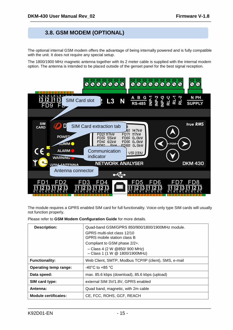
The optional internal GSM modem offers the advantage of being internally powered and is fully compatible with the unit. It does not require any special setup.
The 1800/1900 MHz magnetic antenna together with its 2 meter cable is supplied with the internal modem option. The antenna is intended to be placed outside of the genset panel for the best signal reception.
The module requires a GPRS enabled SIM card for full functionality. Voice-only type SIM cards will usually not function properly.
Please refer to GSM Modem Configuration Guide for more details.
Description: Quad-band GSM/GPRS 850/900/1800/1900MHz module.
GPRS multi-slot class 12/10 GPRS mobile station class B
Compliant to GSM phase 2/2+.
– Class 4 (2 W @850/ 900 MHz) – Class 1 (1 W @ 1800/1900MHz)
Functionality: Web Client, SMTP, Modbus TCP/IP (client), SMS, e-mail
Operating temp range: -40°C to +85 °C
Data speed: max. 85.6 kbps (download), 85.6 kbps (upload)
SIM card type: external SIM 3V/1.8V, GPRS enabled
Antenna: Quad band, magnetic, with 2m cable
Module certificates: CE, FCC, ROHS, GCF, REACH
3.8. GSM MODEM (OPTIONAL)
SIM Card slot
SIM Card extraction tab
Antenna connector
Communication indicator
DKM-430 User Manual Rev_02 Firmware V-1.8
K92D01-EN - 16 -
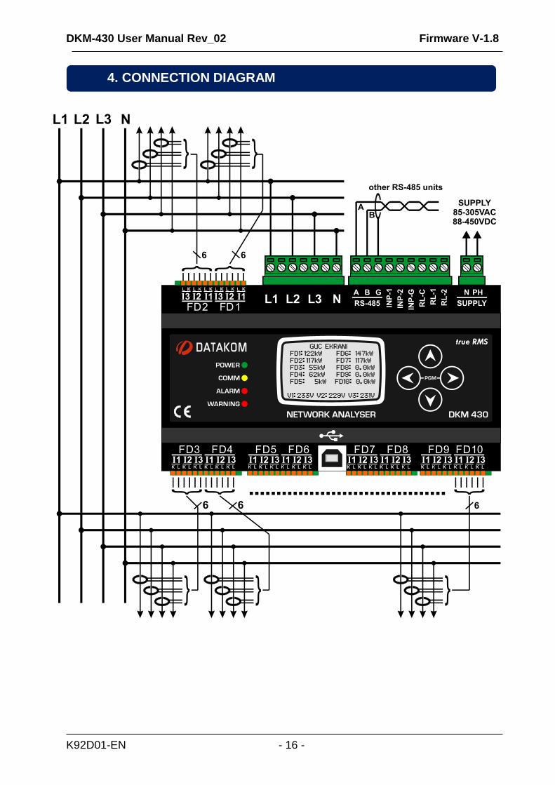
4. CONNECTION DIAGRAM
DKM-430 User Manual Rev_02 Firmware V-1.8
K92D01-EN - 17 -
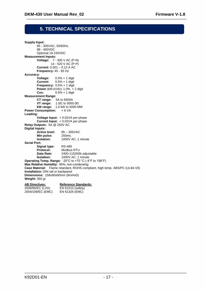
Supply Input:
85 - 305VAC, 50/60Hz, 88 - 450VDC Optional 19-150VDC
Measurement Inputs: Voltage: 7 - 300 V AC (P-N)
14 - 520 V AC (P-P) Current: 0.001 – 0.12 A AC Frequency: 45 - 65 Hz
Accuracy: Voltage: 0.5% + 1 digit
Current: 0.5% + 1 digit Frequency: 0.5% + 1 digit Power (kW,kVAr): 1.0% + 2 digit Cos: 0.5% + 1 digit Measurement Range: CT range: 5A to 6500A
VT range: 1.0/1 to 5000.0/1 kW range: 1.0 kW to 5000 MW
Power Consumption: < 6 VA Loading: Voltage Input: < 0.02VA per phase
Current Input: < 0.02VA per phase Relay Outputs: 5A @ 250V AC Digital Inputs: Active level: 85 – 305VAC Min pulse: 250ms. Isolation: 1000V AC, 1 minute Serial Port: Signal type: RS-485 Protocol: Modbus RTU Data Rate: 2400-115200b adjustable İsolation: 1000V AC, 1 minute Operating Temp. Range: -20°C to +70 °C (-4°F to 158°F) Max Relative Humidity: 95%, non-condensing Case Material: Flame retardant, ROHS compliant, high temp. ABS/PC (UL94-V0) Installation: DIN rail or backpanel Dimensions: 158x90x60mm (WxHxD) Weight: 350 gr
AB Directives:
2006/95/EC (LVD) 2004/108/EC (EMC)
Reference Standards:
EN 61010 (safety) EN 61326 (EMC)
5. TECHNICAL SPECIFICATIONS
DKM-430 User Manual Rev_02 Firmware V-1.8
K92D01-EN - 18 -
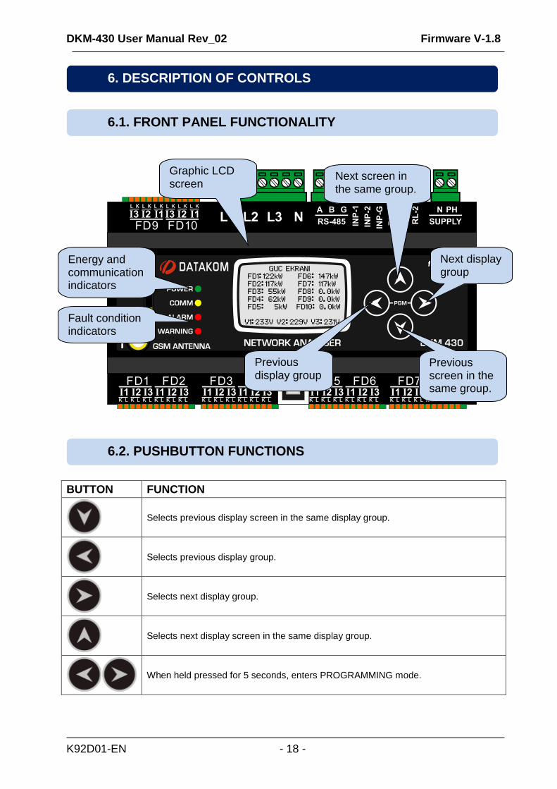
BUTTON FUNCTION
Selects previous display screen in the same display group.
Selects previous display group.
Selects next display group.
Selects next display screen in the same display group.
When held pressed for 5 seconds, enters PROGRAMMING mode.
6.2. PUSHBUTTON FUNCTIONS
6.1. FRONT PANEL FUNCTIONALITY
6. DESCRIPTION OF CONTROLS
Energy and communication indicators
Graphic LCD screen
Next screen in the same group.
Previous display group
Next display group
Previous screen in the same group.
Fault condition indicators
DKM-430 User Manual Rev_02 Firmware V-1.8
K92D01-EN - 19 -
POWER: Turns on as long as energy is supplied to the unit.
COMM: Flashes when the RS-485 Modbus communication is active.
ALARM: Turns on in case of high level alarm (trip condition).
UYARI: Turns on in case of warning.
The unit performs a detailed set of AC measurements. Displaying these parameters are organized under PARAMETER GROUPS and subgroups.
Switching between parameter groups are made with and buttons.
Each depression of the button switches the screen to the next parameter group. After the last group, the first group is displayed again.
Each depression of the button switches the screen to the previous parameter group. After the first group, the last group is displayed again.
Switching within the same group is performed with and buttons.
Each depression of the button switches the screen to the next display in the same group. After the last display, the first display comes again.
Each depression of the button switches the screen to the previous display in the same group. After the first display, the last display comes again.
The list of parameter groups are below:
Channel Measurement Screens: Voltage, current, kW, kVA, kVAr, pf and reactive ratio of each input channel.
Channel Counter Screens: Instantaneous current, demand current, demand power, active and reactive energy counters of each input channel.
Main busbar voltages and frequency: Phase-neutral, phase-phase and average voltages of the main busbar in different screens.
GSM Modem Parameters: Signal level, counters, connection status, IP addresses, etc...
Status Group: Various information as date-time, firmware version, identity, configuration, etc...
User Screens: Screens in this group are configured by the user.
Oscilloscope Screen: In this group, waveforms of currents and voltages may be visualized as an oscilloscope. All phase-neutral and phase-phase voltages and each current input are avalable. Thanks to this feature, waveform distorsions and harmonic components are displayed in graphichal form.
Harmonic Analysis Result Tables: In this group, THDs of currents and voltages are displayed with 0.1% precision. All phase-neutral and phase-phase voltages and each current input are avalable.
6.3. LED FUNCTIONS
6.4. SCREEN SCROLLING
DKM-430 User Manual Rev_02 Firmware V-1.8
K92D01-EN - 20 -
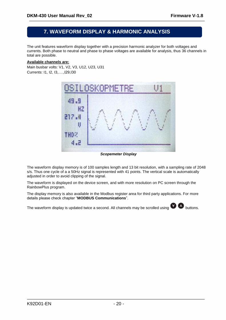
The unit features waveform display together with a precision harmonic analyzer for both voltages and currents. Both phase to neutral and phase to phase voltages are available for analysis, thus 36 channels in total are possible.
Available channels are:
Main busbar volts: V1, V2, V3, U12, U23, U31
Currents: I1, I2, I3,….,I29,I30
Scopemeter Display
The waveform display memory is of 100 samples length and 13 bit resolution, with a sampling rate of 2048 s/s. Thus one cycle of a a 50Hz signal is represented with 41 points. The vertical scale is automatically adjusted in order to avoid clipping of the signal.
The waveform is displayed on the device screen, and with more resolution on PC screen through the RainbowPlus program.
The display memory is also available in the Modbus register area for third party applications. For more details please check chapter “MODBUS Communications”.
The waveform display is updated twice a second. All channels may be scrolled using buttons.
7. WAVEFORM DISPLAY & HARMONIC ANALYSIS
DKM-430 User Manual Rev_02 Firmware V-1.8
K92D01-EN - 21 -
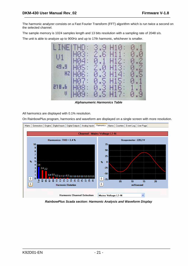
The harmonic analyzer consists on a Fast Fourier Transform (FFT) algorithm which is run twice a second on the selected channel.
The sample memory is 1024 samples length and 13 bits resolution with a sampling rate of 2048 s/s.
The unit is able to analyze up to 900Hz and up to 17th harmonic, whichever is smaller.
Alphanumeric Harmonics Table
All harmonics are displayed with 0.1% resolution.
On RainbowPlus program, harmonics and waveform are displayed on a single screen with more resolution.
RainbowPlus Scada section: Harmonic Analysis and Waveform Display
DKM-430 User Manual Rev_02 Firmware V-1.8
K92D01-EN - 22 -
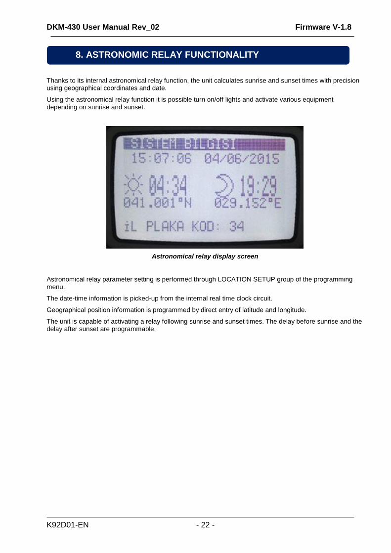
Thanks to its internal astronomical relay function, the unit calculates sunrise and sunset times with precision using geographical coordinates and date.
Using the astronomical relay function it is possible turn on/off lights and activate various equipment depending on sunrise and sunset.
Astronomical relay display screen
Astronomical relay parameter setting is performed through LOCATION SETUP group of the programming menu.
The date-time information is picked-up from the internal real time clock circuit.
Geographical position information is programmed by direct entry of latitude and longitude.
The unit is capable of activating a relay following sunrise and sunset times. The delay before sunrise and the delay after sunset are programmable.
8. ASTRONOMIC RELAY FUNCTIONALITY
DKM-430 User Manual Rev_02 Firmware V-1.8
K92D01-EN - 23 -
Measured analog values outside of programed limits cause an ALARM condition.
Alarms cause below, actions to be taken:
The ALARM led to turn on steadily,
The Alarm digital output to operate.
Alarms operate in a first occurring basis:
-If an alarm is present, following alarms will not be accepted,
Alarms may be of LATCHING type following programming. For latching alarms, even if the alarm condition is
removed, the alarms will stay on and disable the operation of the genset.
Most alarms have programmable trip levels. See the programming chapter for adjustable alarm limits.
If a fault condition occurs, the display will automatically switch to the ALARM LIST page.
9. PROTECTIONS AND ALARMS
DKM-430 User Manual Rev_02 Firmware V-1.8
K92D01-EN - 24 -
The program mode is used to adjust timers, operational limits and the configuration of the unit.
Although a free PC program is provided for programming, every parameter may be modified through the front
panel, regardless of the operating mode.
When modified, program parameters are automatically recorded into a non-erasable memory and take effect
immediately.
The program mode will not affect the operation of the unit. Thus programs may be modified anytime.
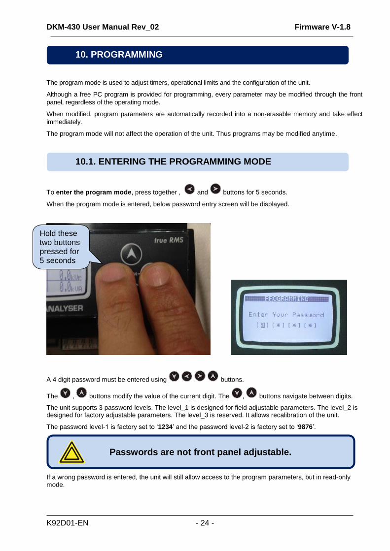
To enter the program mode, press together , and buttons for 5 seconds.
When the program mode is entered, below password entry screen will be displayed.
A 4 digit password must be entered using buttons.
The , buttons modify the value of the current digit. The , buttons navigate between digits.
The unit supports 3 password levels. The level_1 is designed for field adjustable parameters. The level_2 is designed for factory adjustable parameters. The level_3 is reserved. It allows recalibration of the unit.
The password level-1 is factory set to ‘1234’ and the password level-2 is factory set to ‘9876’.
If a wrong password is entered, the unit will still allow access to the program parameters, but in read-only mode.
Passwords are not front panel adjustable.
10.1. ENTERING THE PROGRAMMING MODE
10. PROGRAMMING
Hold these two buttons pressed for 5 seconds seconds
DKM-430 User Manual Rev_02 Firmware V-1.8
K92D01-EN - 25 -
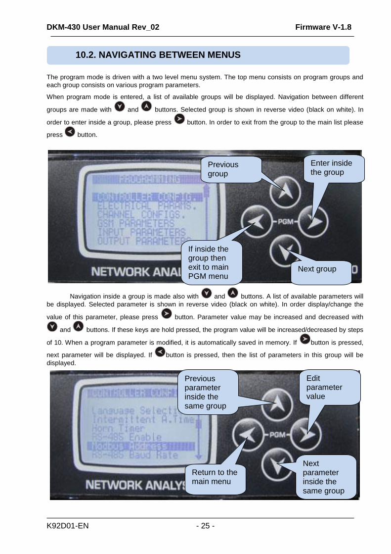
The program mode is driven with a two level menu system. The top menu consists on program groups and
each group consists on various program parameters.
When program mode is entered, a list of available groups will be displayed. Navigation between different
groups are made with and buttons. Selected group is shown in reverse video (black on white). In
order to enter inside a group, please press button. In order to exit from the group to the main list please
press button.
Navigation inside a group is made also with and buttons. A list of available parameters will
be displayed. Selected parameter is shown in reverse video (black on white). In order display/change the
value of this parameter, please press button. Parameter value may be increased and decreased with
and buttons. If these keys are hold pressed, the program value will be increased/decreased by steps
of 10. When a program parameter is modified, it is automatically saved in memory. If button is pressed,
next parameter will be displayed. If button is pressed, then the list of parameters in this group will be
displayed.
10.2. NAVIGATING BETWEEN MENUS
Next group
If inside the group then exit to main PGM menu
Previous group
Enter inside the group
Return to the main menu
Next parameter inside the same group
Edit parameter value
Previous parameter inside the same group
DKM-430 User Manual Rev_02 Firmware V-1.8
K92D01-EN - 26 -
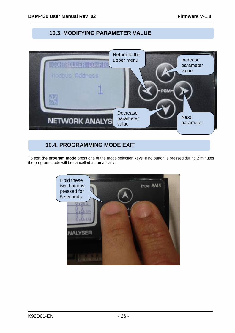
To exit the program mode press one of the mode selection keys. If no button is pressed during 2 minutes the program mode will be cancelled automatically.
10.3. MODIFYING PARAMETER VALUE
10.4. PROGRAMMING MODE EXIT
Decrease parameter value
Increase parameter value
Return to the upper menu
Next parameter
Hold these two buttons pressed for 5 seconds seconds
DKM-430 User Manual Rev_02 Firmware V-1.8
K92D01-EN - 27 -
Parameter Definition Unit Min Max Factory Set
Description
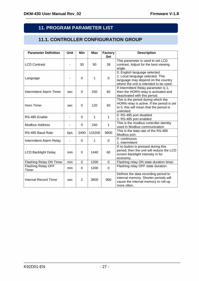
LCD Contrast - 30 50 39 This parameter is used to set LCD contrast. Adjust for the best viewing angle.
Language - 0 1 0
0: English language selected. 1: Local language selected. This language may depend on the country where the unit is intended to be used.
Intermittent Alarm Timer sec 0 250 60 If Intermittent Relay parameter is 1, then the HORN relay is activated and deactivated with this period.
Horn Timer sec 0 120 60
This is the period during which the HORN relay is active. If the period is set to 0, this will mean that the period is unlimited.
RS-485 Enable - 0 1 1 0: RS-485 port disabled 1: RS-485 port enabled
Modbus Address - 0 240 1 This is the modbus controller identity used in Modbus communication.
RS-485 Baud Rate bps 2400 115200 9600 This is the data rate of the RS-485 Modbus port.
Intermittent Alarm Relay - 0 1 0 0: continuous 1: intermittent
LCD Backlight Delay min 0 1440 60
If no button is pressed during this period, then the unit will reduce the LCD screen backlight intensity in for economy.
Flashing Relay ON Timer min 0 1200 0 Flashing relay ON state duration timer.
Flashing Relay OFF Timer
min 0 1200 0 Flashing relay OFF state duration.
Internal Record Timer sec 2 3600 900
Defines the data recording period to internal memory. Shorter periods will cause the internal memory to roll-up more often.
11. PROGRAM PARAMETER LIST
11.1. CONTROLLER CONFIGURATION GROUP

DKM-430 User Manual Rev_02 Firmware V-1.8
K92D01-EN - 28 -
Parameter Definition Unit Min Max Factory Set
Description
Current Transformer Primary
Amp 1 5000 500
This is the rated value of current transformers. All transformers must have the same rating. The secondary of the transformer will be 0.1 Amps.
Voltage Transformer Ratio
- 0 5000 1.0
This is the voltage transformer ratio. This value will multiply all voltage and power readings. If transformers are not used, the ratio should be set to 1.0
Alarm Mute Timer sec 0 10 1 If the alarm is selected non-latching, then the alarm condition disappears this timer after the alarm signal goes off.
Mains Phase Order Check Enable
- 0 1 0 0: mains phase order checking disabled 1: if mains phase order is faulty, then an alarm occurs.
Low Voltage Alarm Limit V 0 65000 0
If the voltage of any phase falls below this limit, this will cause an alarm. If this limit is 0 then low voltage alarm is not controlled.
High Voltage Alarm Limit V 0 65000 0
If the voltage of any phase goes above this limit, this will cause an alarm. If this limit is 0 then high voltage alarm is not controlled.
Voltage Fail Timer sec 0 255 1 If the voltage goes outside limits during this timer, a voltage alarm will occur.
Voltage Alarm Lock Enable
- 0 1 1 0: alarm non latching 1: latching alarm
Frequency Low Alarm Hz 0 400 0
If the frequency goes under this limit, this will cause an alarm. If this limit is 0 then the alarm is not controlled.
Frequency High Alarm Hz 0 400 0
If the frequency goes above this limit, this will cause an alarm. If this limit is 0 then the alarm is not controlled.
Frequency Alarm Duration
sec 0 255 1 If the frequency goes outside of the limits during this timer, a frequency alarm will occur.
Frequency Alarm Lock Enable
- 0 1 1 0: alarm non latching 1: latching alarm
Active Power Low Alarm kW 0 400 0
If the active power of any channel goes under this limit, this will cause an alarm. If this limit is 0 then the alarm is not controlled.
Active Power High Alarm kW 0 400 0
If the active power of any channel goes above this limit, this will cause an alarm. If this limit is 0 then the alarm is not controlled.
Active Power Alarm Duration
sec 0 255 1 If the active power of any channel goes outside of the limits during this timer, an active power alarm will occur.
Active Power Alarm Lock Enable
- 0 1 1 0: alarm non latching 1: latching alarm
11.2. ELECTRICAL PARAMETERS GROUP
DKM-430 User Manual Rev_02 Firmware V-1.8
K92D01-EN - 29 -
Parameter Definition Unit Min Max Factory Set
Description
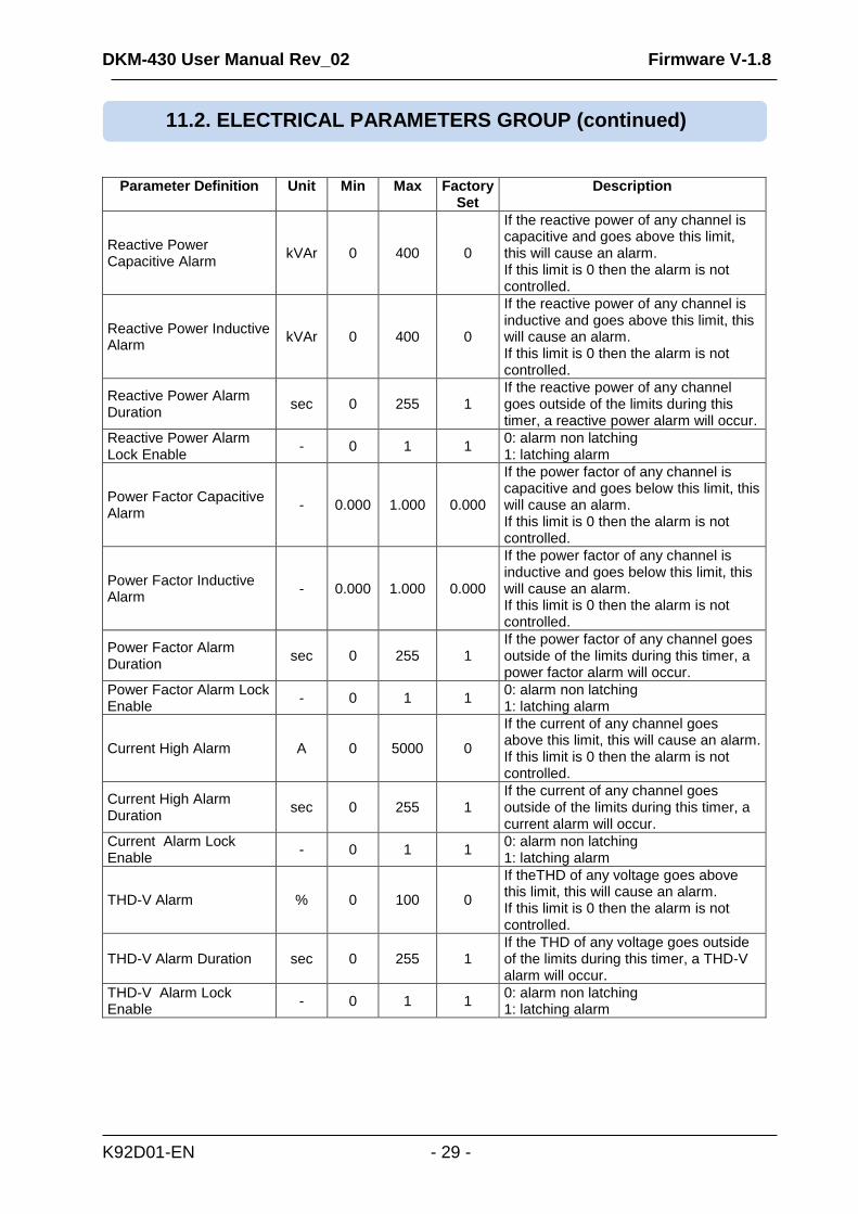
Reactive Power Capacitive Alarm
kVAr 0 400 0
If the reactive power of any channel is capacitive and goes above this limit, this will cause an alarm. If this limit is 0 then the alarm is not controlled.
Reactive Power Inductive Alarm
kVAr 0 400 0
If the reactive power of any channel is inductive and goes above this limit, this will cause an alarm. If this limit is 0 then the alarm is not controlled.
Reactive Power Alarm Duration
sec 0 255 1 If the reactive power of any channel goes outside of the limits during this timer, a reactive power alarm will occur.
Reactive Power Alarm Lock Enable
- 0 1 1 0: alarm non latching 1: latching alarm
Power Factor Capacitive Alarm
- 0.000 1.000 0.000
If the power factor of any channel is capacitive and goes below this limit, this will cause an alarm. If this limit is 0 then the alarm is not controlled.
Power Factor Inductive Alarm
- 0.000 1.000 0.000
If the power factor of any channel is inductive and goes below this limit, this will cause an alarm. If this limit is 0 then the alarm is not controlled.
Power Factor Alarm Duration
sec 0 255 1 If the power factor of any channel goes outside of the limits during this timer, a power factor alarm will occur.
Power Factor Alarm Lock Enable
- 0 1 1 0: alarm non latching 1: latching alarm
Current High Alarm A 0 5000 0
If the current of any channel goes above this limit, this will cause an alarm. If this limit is 0 then the alarm is not controlled.
Current High Alarm Duration
sec 0 255 1 If the current of any channel goes outside of the limits during this timer, a current alarm will occur.
Current Alarm Lock Enable
- 0 1 1 0: alarm non latching 1: latching alarm
THD-V Alarm % 0 100 0
If theTHD of any voltage goes above this limit, this will cause an alarm. If this limit is 0 then the alarm is not controlled.
THD-V Alarm Duration sec 0 255 1 If the THD of any voltage goes outside of the limits during this timer, a THD-V alarm will occur.
THD-V Alarm Lock Enable
- 0 1 1 0: alarm non latching 1: latching alarm
11.2. ELECTRICAL PARAMETERS GROUP (continued)
DKM-430 User Manual Rev_02 Firmware V-1.8
K92D01-EN - 30 -
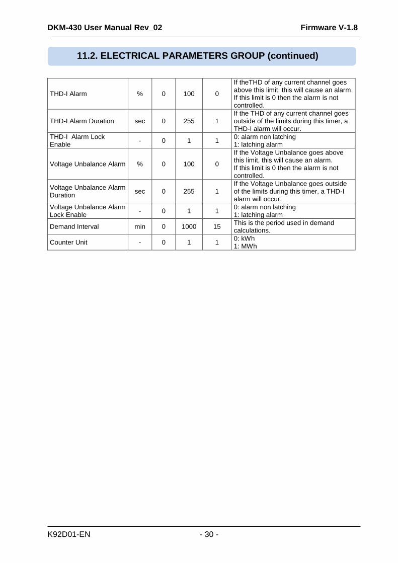
THD-I Alarm % 0 100 0
If theTHD of any current channel goes above this limit, this will cause an alarm. If this limit is 0 then the alarm is not controlled.
THD-I Alarm Duration sec 0 255 1 If the THD of any current channel goes outside of the limits during this timer, a THD-I alarm will occur.
THD-I Alarm Lock Enable
- 0 1 1 0: alarm non latching 1: latching alarm
Voltage Unbalance Alarm % 0 100 0
If the Voltage Unbalance goes above this limit, this will cause an alarm. If this limit is 0 then the alarm is not controlled.
Voltage Unbalance Alarm Duration
sec 0 255 1 If the Voltage Unbalance goes outside of the limits during this timer, a THD-I alarm will occur.
Voltage Unbalance Alarm Lock Enable
- 0 1 1 0: alarm non latching 1: latching alarm
Demand Interval min 0 1000 15 This is the period used in demand calculations.
Counter Unit - 0 1 1 0: kWh 1: MWh
11.2. ELECTRICAL PARAMETERS GROUP (continued)
DKM-430 User Manual Rev_02 Firmware V-1.8
K92D01-EN - 31 -
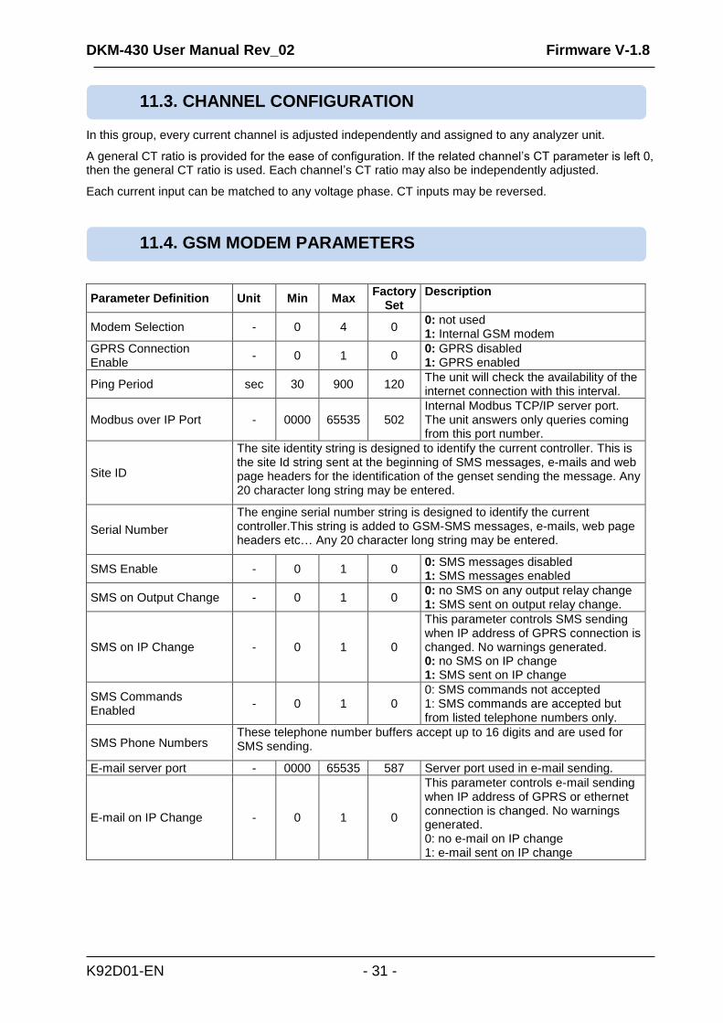
In this group, every current channel is adjusted independently and assigned to any analyzer unit.
A general CT ratio is provided for the ease of configuration. If the related channel’s CT parameter is left 0, then the general CT ratio is used. Each channel’s CT ratio may also be independently adjusted.
Each current input can be matched to any voltage phase. CT inputs may be reversed.
Parameter Definition Unit Min Max Factory
Set Description
Modem Selection - 0 4 0 0: not used 1: Internal GSM modem
GPRS Connection Enable
- 0 1 0 0: GPRS disabled 1: GPRS enabled
Ping Period sec 30 900 120 The unit will check the availability of the internet connection with this interval.
Modbus over IP Port - 0000 65535 502 Internal Modbus TCP/IP server port. The unit answers only queries coming from this port number.
Site ID
The site identity string is designed to identify the current controller. This is the site Id string sent at the beginning of SMS messages, e-mails and web page headers for the identification of the genset sending the message. Any 20 character long string may be entered.
Serial Number
The engine serial number string is designed to identify the current controller.This string is added to GSM-SMS messages, e-mails, web page headers etc… Any 20 character long string may be entered.
SMS Enable - 0 1 0 0: SMS messages disabled 1: SMS messages enabled
SMS on Output Change - 0 1 0 0: no SMS on any output relay change 1: SMS sent on output relay change.
SMS on IP Change - 0 1 0
This parameter controls SMS sending when IP address of GPRS connection is changed. No warnings generated. 0: no SMS on IP change 1: SMS sent on IP change
SMS Commands Enabled
- 0 1 0 0: SMS commands not accepted 1: SMS commands are accepted but from listed telephone numbers only.
SMS Phone Numbers These telephone number buffers accept up to 16 digits and are used for SMS sending.
E-mail server port - 0000 65535 587 Server port used in e-mail sending.
E-mail on IP Change - 0 1 0
This parameter controls e-mail sending when IP address of GPRS or ethernet connection is changed. No warnings generated. 0: no e-mail on IP change 1: e-mail sent on IP change
11.4. GSM MODEM PARAMETERS
11.3. CHANNEL CONFIGURATION
DKM-430 User Manual Rev_02 Firmware V-1.8
K92D01-EN - 32 -
Parameter Definition Unit Min Max Factory
Set Description
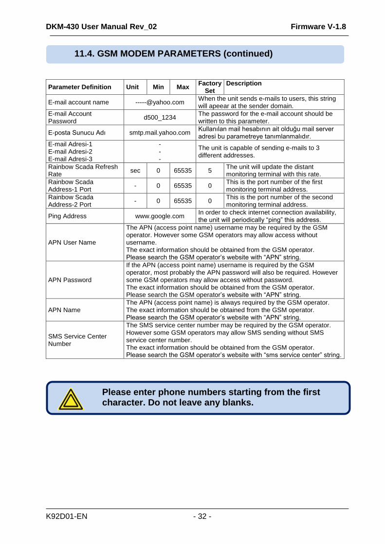
E-mail account name [email protected] When the unit sends e-mails to users, this string will apeear at the sender domain.
E-mail Account Password
d500_1234 The password for the e-mail account should be written to this parameter.
E-posta Sunucu Adı smtp.mail.yahoo.com Kullanılan mail hesabının ait olduğu mail server adresi bu parametreye tanımlanmalıdır.
E-mail Adresi-1 E-mail Adresi-2 E-mail Adresi-3
- - -
The unit is capable of sending e-mails to 3 different addresses.
Rainbow Scada Refresh Rate
sec 0 65535 5 The unit will update the distant monitoring terminal with this rate.
Rainbow Scada Address-1 Port
- 0 65535 0 This is the port number of the first monitoring terminal address.
Rainbow Scada Address-2 Port
- 0 65535 0 This is the port number of the second monitoring terminal address.
Ping Address www.google.com In order to check internet connection availability, the unit will periodically “ping” this address.
APN User Name
The APN (access point name) username may be required by the GSM operator. However some GSM operators may allow access without username. The exact information should be obtained from the GSM operator. Please search the GSM operator’s website with “APN” string.
APN Password
If the APN (access point name) username is required by the GSM operator, most probably the APN password will also be required. However some GSM operators may allow access without password. The exact information should be obtained from the GSM operator. Please search the GSM operator’s website with “APN” string.
APN Name The APN (access point name) is always required by the GSM operator. The exact information should be obtained from the GSM operator. Please search the GSM operator’s website with “APN” string.
SMS Service Center Number
The SMS service center number may be required by the GSM operator. However some GSM operators may allow SMS sending without SMS service center number. The exact information should be obtained from the GSM operator. Please search the GSM operator’s website with “sms service center” string.
Please enter phone numbers starting from the first character. Do not leave any blanks.
11.4. GSM MODEM PARAMETERS (continued)
DKM-430 User Manual Rev_02 Firmware V-1.8
K92D01-EN - 33 -
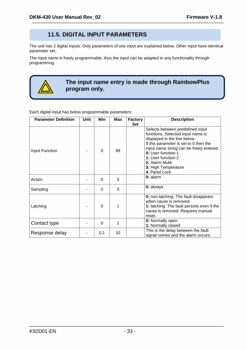
The unit has 2 digital inputs. Only parameters of one input are explained below. Other input have identical parameter set.
The input name is freely programmable, thus the input can be adapted to any functionality through programming.
Each digital input has below programmable parameters:
Parameter Definition Unit Min Max Factory Set
Description
Input Function - 0 99
Selects between predefined input functions. Selected input name is displayed in the line below. If this parameter is set to 0 then the input name string can be freely entered. 0: User function-1 1: User function-2 2: Alarm Mute 3: High Temperature 4: Panel Lock
Action - 0 3 0: alarm
Sampling - 0 3 0: always
Latching - 0 1
0: non-latching. The fault disappears when cause is removed. 1: latching. The fault persists even if the cause is removed. Requires manual reset.
Contact type - 0 1 0: Normally open 1: Normally closed
Response delay - 0.1 10 This is the delay between the fault signal comes and the alarm occurs.
The input name entry is made through RainbowPlus program only.
11.5. DIGITAL INPUT PARAMETERS
DKM-430 User Manual Rev_02 Firmware V-1.8
K92D01-EN - 34 -
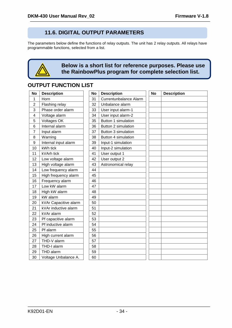
The parameters below define the functions of relay outputs. The unit has 2 relay outputs. All relays have programmable functions, selected from a list.
OUTPUT FUNCTION LIST
No Description
1 Horn
2 Flashing relay
3 Phase order alarm
4 Voltage alarm
5 Voltages OK
6 Internal alarm
7 Input alarm
8 Warning
9 Internal input alarm
10 kWh tick
11 kVArh tick
12 Low voltage alarm
13 High voltage alarm
14 Low frequency alarm
15 High frequency alarm
16 Frequency alarm
17 Low kW alarm
18 High kW alarm
19 kW alarm
20 kVAr Capacitive alarm
21 kVAr inductive alarm
22 kVAr alarm
23 Pf capacitive alarm
24 Pf inductive alarm
25 Pf alarm
26 High current alarm
27 THD-V alarm
28 THD-I alarm
29 THD alarm
30 Voltage Unbalance A.
No Description
31 Currentunbalance Alarm
32 Unbalance alarm
33 User input alarm-1
34 User input alarm-2
35 Button 1 simulation
36 Button 2 simulation
37 Button 3 simulation
38 Button 4 simulation
39 Input-1 simulation
40 Input-2 simulation
41 User output 1
42 User output 2
43 Astronomical relay
44
45
46
47
48
49
50
51
52
53
54
55
56
57
58
59
60
No Description
Below is a short list for reference purposes. Please use the RainbowPlus program for complete selection list.
11.6. DIGITAL OUTPUT PARAMETERS
DKM-430 User Manual Rev_02 Firmware V-1.8
K92D01-EN - 35 -
In this group various texts are entered. These texts appear at top of user screens, as special names for digital inputs or analyzer module names.
In this group, restarting of demand periods and counter value settings are performed.
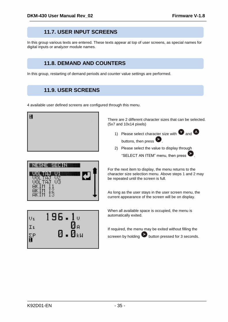
4 available user defined screens are configured through this menu.
There are 2 different character sizes that can be selected.
(5x7 and 10x14 pixels)
1) Please select character size with and
buttons, then press .
2) Please select the value to display through
“SELECT AN ITEM” menu, then press .
For the next item to display, the menu returns to the
character size selection menu. Above steps 1 and 2 may
be repeated until the screen is full.
As long as the user stays in the user screen menu, the
current appearance of the screen will be on display.
When all available space is occupied, the menu is
automatically exited.
If required, the menu may be exited without filling the
screeen by holding button pressed for 3 seconds.
11.9. USER SCREENS
11.8. DEMAND AND COUNTERS
11.7. USER INPUT SCREENS

DKM-430 User Manual Rev_02 Firmware V-1.8
K92D01-EN - 36 -
The unit is calibrated during factory production, but it is possible to calibrate again.
Please select “DEVICE CALIBRATION” menu from PROGRAMMING section.
Then select the input with and buttons and press
.
Then adjust the coefficient in order to display the correct
measured value on the screen and press button in order
to save the new calibration and return to PROGRAMMING
section.
These parameters allow adjusting the battery backup real time clock of the module. Once set, the clock will continue to run even if supply power is removed from the unit.
Parameter Definition Unit Min Max Description
Date - 01 31 Current day of the month.
Month - 01 12 Current month.
Year - 00 99 Last two digits of the current year.
Hours - 00 23 Current hour of the day.
Minutes - 00 59 Current minute of the hour.
Seconds - 00 59 Current second of the minute.
11.10. DEVICE CALIBRATION
11.11. ADJUST DATE AND TIME
MEASURED VALUE
DKM-430 User Manual Rev_02 Firmware V-1.8
K92D01-EN - 37 -
The unit has 3 different password levels. Each password consists on a 4 digit number.
When this menu is selected, the unit will ask for confirmation.
Please adjust required selection with and buttons, then press in order to return to PROGRAMMING section.
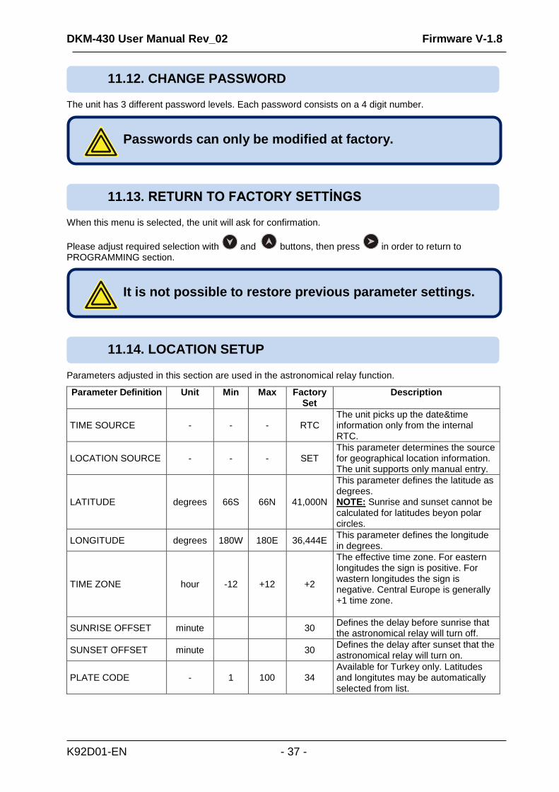
Parameters adjusted in this section are used in the astronomical relay function.
Parameter Definition Unit Min Max Factory Set
Description
TIME SOURCE - - - RTC The unit picks up the date&time information only from the internal RTC.
LOCATION SOURCE - - - SET This parameter determines the source for geographical location information. The unit supports only manual entry.
LATITUDE degrees 66S 66N 41,000N
This parameter defines the latitude as degrees. NOTE: Sunrise and sunset cannot be calculated for latitudes beyon polar circles.
LONGITUDE degrees 180W 180E 36,444E This parameter defines the longitude in degrees.
TIME ZONE hour -12 +12 +2
The effective time zone. For eastern longitudes the sign is positive. For wastern longitudes the sign is negative. Central Europe is generally +1 time zone.
SUNRISE OFFSET minute 30 Defines the delay before sunrise that the astronomical relay will turn off.
SUNSET OFFSET minute 30 Defines the delay after sunset that the astronomical relay will turn on.
PLATE CODE - 1 100 34 Available for Turkey only. Latitudes and longitutes may be automatically selected from list.
It is not possible to restore previous parameter settings.
Passwords can only be modified at factory.
11.14. LOCATION SETUP
11.13. RETURN TO FACTORY SETTİNGS
11.12. CHANGE PASSWORD
DKM-430 User Manual Rev_02 Firmware V-1.8
K92D01-EN - 38 -
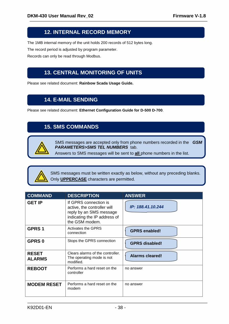
The 1MB internal memory of the unit holds 200 records of 512 bytes long.
The record period is adjusted by program parameter.
Records can only be read through Modbus.
Please see related document: Rainbow Scada Usage Guide.
Please see related document: Ethernet Configuration Guide for D-500 D-700.
COMMAND DESCRIPTION ANSWER
GET IP
If GPRS connection is active, the controller will reply by an SMS message indicating the IP address of the GSM modem.
GPRS 1 Activates the GPRS connection
GPRS 0 Stops the GPRS connection
RESET ALARMS
Clears alarms of the controller. The operating mode is not modified.
REBOOT Performs a hard reset on the controller
no answer
MODEM RESET Performs a hard reset on the modem
no answer
12. INTERNAL RECORD MEMORY
SMS messages must be written exactly as below, without any preceding blanks.
Only UPPERCASE characters are permitted.
SMS messages are accepted only from phone numbers recorded in the GSM PARAMETERS>SMS TEL NUMBERS tab.
Answers to SMS messages will be sent to all phone numbers in the list.
Alarms cleared!
GPRS disabled!
GPRS enabled!
IP: 188.41.10.244
14. E-MAIL SENDING
13. CENTRAL MONITORING OF UNITS
15. SMS COMMANDS
DKM-430 User Manual Rev_02 Firmware V-1.8
K92D01-EN - 39 -
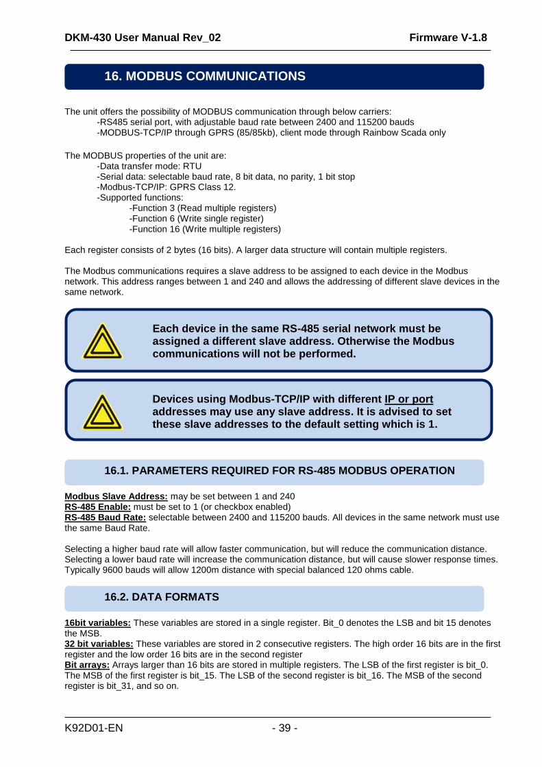
The unit offers the possibility of MODBUS communication through below carriers:
-RS485 serial port, with adjustable baud rate between 2400 and 115200 bauds -MODBUS-TCP/IP through GPRS (85/85kb), client mode through Rainbow Scada only
The MODBUS properties of the unit are: -Data transfer mode: RTU -Serial data: selectable baud rate, 8 bit data, no parity, 1 bit stop -Modbus-TCP/IP: GPRS Class 12. -Supported functions: -Function 3 (Read multiple registers) -Function 6 (Write single register)
-Function 16 (Write multiple registers) Each register consists of 2 bytes (16 bits). A larger data structure will contain multiple registers. The Modbus communications requires a slave address to be assigned to each device in the Modbus network. This address ranges between 1 and 240 and allows the addressing of different slave devices in the same network.
Modbus Slave Address: may be set between 1 and 240 RS-485 Enable: must be set to 1 (or checkbox enabled) RS-485 Baud Rate: selectable between 2400 and 115200 bauds. All devices in the same network must use the same Baud Rate. Selecting a higher baud rate will allow faster communication, but will reduce the communication distance. Selecting a lower baud rate will increase the communication distance, but will cause slower response times. Typically 9600 bauds will allow 1200m distance with special balanced 120 ohms cable.
16bit variables: These variables are stored in a single register. Bit_0 denotes the LSB and bit 15 denotes the MSB. 32 bit variables: These variables are stored in 2 consecutive registers. The high order 16 bits are in the first register and the low order 16 bits are in the second register Bit arrays: Arrays larger than 16 bits are stored in multiple registers. The LSB of the first register is bit_0. The MSB of the first register is bit_15. The LSB of the second register is bit_16. The MSB of the second register is bit_31, and so on.
16.2. DATA FORMATS
16.1. PARAMETERS REQUIRED FOR RS-485 MODBUS OPERATION
Devices using Modbus-TCP/IP with different IP or port addresses may use any slave address. It is advised to set these slave addresses to the default setting which is 1.
Each device in the same RS-485 serial network must be assigned a different slave address. Otherwise the Modbus communications will not be performed.
16. MODBUS COMMUNICATIONS
DKM-430 User Manual Rev_02 Firmware V-1.8
K92D01-EN - 40 -
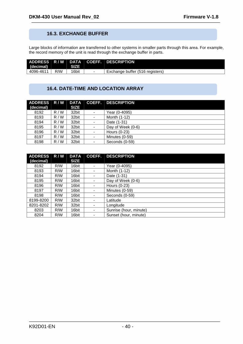
Large blocks of information are transferred to other systems in smaller parts through this area. For example, the record memory of the unit is read through the exchange buffer in parts.
ADDRESS (decimal)
R / W DATA SIZE
COEFF. DESCRIPTION
4096-4611 R/W 16bit - Exchange buffer (516 registers)
ADDRESS (decimal)
R / W DATA SIZE
COEFF. DESCRIPTION
8192 R / W 32bit - Year (0-4095)
8193 R / W 32bit - Month (1-12)
8194 R / W 32bit - Date (1-31)
8195 R / W 32bit - Day of Week (0-6)
8196 R / W 32bit - Hours (0-23)
8197 R / W 32bit - Minutes (0-59)
8198 R / W 32bit - Seconds (0-59)
ADDRESS (decimal)
R / W DATA SIZE
COEFF. DESCRIPTION
8192 R/W 16bit - Year (0-4095)
8193 R/W 16bit - Month (1-12)
8194 R/W 16bit - Date (1-31)
8195 R/W 16bit - Day of Week (0-6)
8196 R/W 16bit - Hours (0-23)
8197 R/W 16bit - Minutes (0-59)
8198 R/W 16bit - Seconds (0-59)
8199-8200 R/W 32bit - Latitude
8201-8202 R/W 32bit - Longitude
8203 R/W 16bit - Sunrise (hour, minute)
8204 R/W 16bit - Sunset (hour, minute)
16.4. DATE-TIME AND LOCATION ARRAY
16.3. EXCHANGE BUFFER
DKM-430 User Manual Rev_02 Firmware V-1.8
K92D01-EN - 41 -
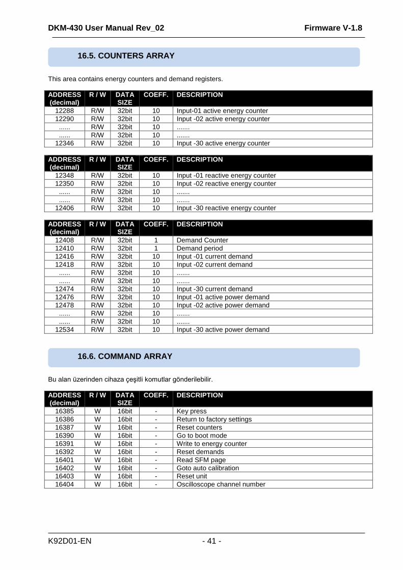
This area contains energy counters and demand registers.
ADDRESS (decimal)
R / W DATA SIZE
COEFF. DESCRIPTION
12288 R/W 32bit 10 Input-01 active energy counter
12290 R/W 32bit 10 Input -02 active energy counter
...... R/W 32bit 10 .......
...... R/W 32bit 10 .......
12346 R/W 32bit 10 Input -30 active energy counter
ADDRESS (decimal)
R / W DATA SIZE
COEFF. DESCRIPTION
12348 R/W 32bit 10 Input -01 reactive energy counter
12350 R/W 32bit 10 Input -02 reactive energy counter
...... R/W 32bit 10 .......
...... R/W 32bit 10 .......
12406 R/W 32bit 10 Input -30 reactive energy counter
ADDRESS (decimal)
R / W DATA SIZE
COEFF. DESCRIPTION
12408 R/W 32bit 1 Demand Counter
12410 R/W 32bit 1 Demand period
12416 R/W 32bit 10 Input -01 current demand
12418 R/W 32bit 10 Input -02 current demand
...... R/W 32bit 10 .......
...... R/W 32bit 10 .......
12474 R/W 32bit 10 Input -30 current demand
12476 R/W 32bit 10 Input -01 active power demand
12478 R/W 32bit 10 Input -02 active power demand
...... R/W 32bit 10 .......
...... R/W 32bit 10 .......
12534 R/W 32bit 10 Input -30 active power demand
Bu alan üzerinden cihaza çeşitli komutlar gönderilebilir.
ADDRESS (decimal)
R / W DATA SIZE
COEFF. DESCRIPTION
16385 W 16bit - Key press
16386 W 16bit - Return to factory settings
16387 W 16bit - Reset counters
16390 W 16bit - Go to boot mode
16391 W 16bit - Write to energy counter
16392 W 16bit - Reset demands
16401 W 16bit - Read SFM page
16402 W 16bit - Goto auto calibration
16403 W 16bit - Reset unit
16404 W 16bit - Oscilloscope channel number
16.6. COMMAND ARRAY
16.5. COUNTERS ARRAY
DKM-430 User Manual Rev_02 Firmware V-1.8
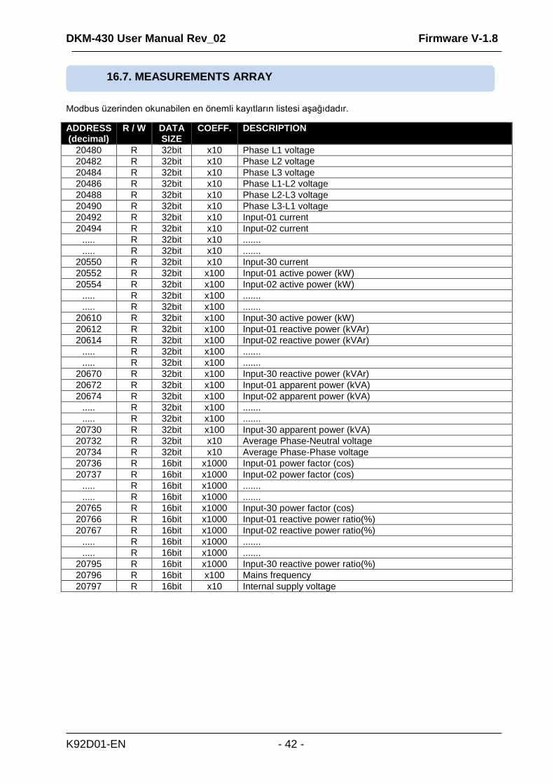
K92D01-EN - 42 -
Modbus üzerinden okunabilen en önemli kayıtların listesi aşağıdadır.
ADDRESS (decimal)
R / W DATA SIZE
COEFF. DESCRIPTION
20480 R 32bit x10 Phase L1 voltage
20482 R 32bit x10 Phase L2 voltage
20484 R 32bit x10 Phase L3 voltage
20486 R 32bit x10 Phase L1-L2 voltage
20488 R 32bit x10 Phase L2-L3 voltage
20490 R 32bit x10 Phase L3-L1 voltage
20492 R 32bit x10 Input-01 current
20494 R 32bit x10 Input-02 current
..... R 32bit x10 .......
..... R 32bit x10 .......
20550 R 32bit x10 Input-30 current
20552 R 32bit x100 Input-01 active power (kW)
20554 R 32bit x100 Input-02 active power (kW)
..... R 32bit x100 .......
..... R 32bit x100 .......
20610 R 32bit x100 Input-30 active power (kW)
20612 R 32bit x100 Input-01 reactive power (kVAr)
20614 R 32bit x100 Input-02 reactive power (kVAr)
..... R 32bit x100 .......
..... R 32bit x100 .......
20670 R 32bit x100 Input-30 reactive power (kVAr)
20672 R 32bit x100 Input-01 apparent power (kVA)
20674 R 32bit x100 Input-02 apparent power (kVA)
..... R 32bit x100 .......
..... R 32bit x100 .......
20730 R 32bit x100 Input-30 apparent power (kVA)
20732 R 32bit x10 Average Phase-Neutral voltage
20734 R 32bit x10 Average Phase-Phase voltage
20736 R 16bit x1000 Input-01 power factor (cos)
20737 R 16bit x1000 Input-02 power factor (cos)
..... R 16bit x1000 .......
..... R 16bit x1000 .......
20765 R 16bit x1000 Input-30 power factor (cos)
20766 R 16bit x1000 Input-01 reactive power ratio(%)
20767 R 16bit x1000 Input-02 reactive power ratio(%)
..... R 16bit x1000 .......
..... R 16bit x1000 .......
20795 R 16bit x1000 Input-30 reactive power ratio(%)
20796 R 16bit x100 Mains frequency
20797 R 16bit x10 Internal supply voltage
16.7. MEASUREMENTS ARRAY
DKM-430 User Manual Rev_02 Firmware V-1.8
K92D01-EN - 43 -
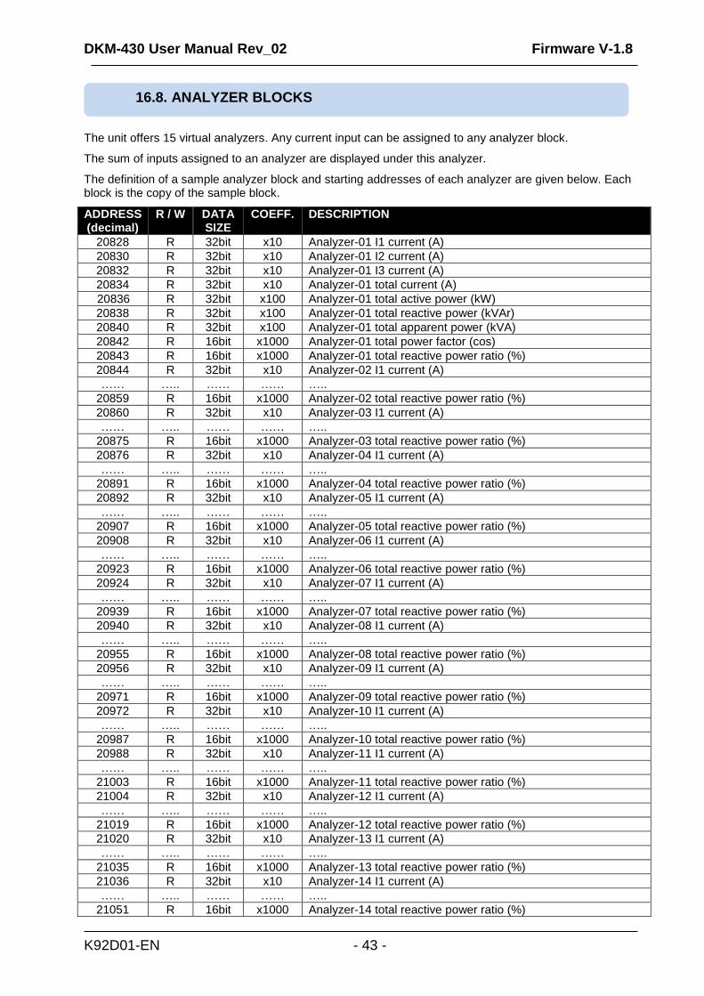
The unit offers 15 virtual analyzers. Any current input can be assigned to any analyzer block.
The sum of inputs assigned to an analyzer are displayed under this analyzer.
The definition of a sample analyzer block and starting addresses of each analyzer are given below. Each block is the copy of the sample block.
ADDRESS (decimal)
R / W DATA SIZE
COEFF. DESCRIPTION
20828 R 32bit x10 Analyzer-01 I1 current (A)
20830 R 32bit x10 Analyzer-01 I2 current (A)
20832 R 32bit x10 Analyzer-01 I3 current (A)
20834 R 32bit x10 Analyzer-01 total current (A)
20836 R 32bit x100 Analyzer-01 total active power (kW)
20838 R 32bit x100 Analyzer-01 total reactive power (kVAr)
20840 R 32bit x100 Analyzer-01 total apparent power (kVA)
20842 R 16bit x1000 Analyzer-01 total power factor (cos)
20843 R 16bit x1000 Analyzer-01 total reactive power ratio (%)
20844 R 32bit x10 Analyzer-02 I1 current (A)
…… ….. …… …… …..
20859 R 16bit x1000 Analyzer-02 total reactive power ratio (%)
20860 R 32bit x10 Analyzer-03 I1 current (A)
…… ….. …… …… …..
20875 R 16bit x1000 Analyzer-03 total reactive power ratio (%)
20876 R 32bit x10 Analyzer-04 I1 current (A)
…… ….. …… …… …..
20891 R 16bit x1000 Analyzer-04 total reactive power ratio (%)
20892 R 32bit x10 Analyzer-05 I1 current (A)
…… ….. …… …… …..
20907 R 16bit x1000 Analyzer-05 total reactive power ratio (%)
20908 R 32bit x10 Analyzer-06 I1 current (A)
…… ….. …… …… …..
20923 R 16bit x1000 Analyzer-06 total reactive power ratio (%)
20924 R 32bit x10 Analyzer-07 I1 current (A)
…… ….. …… …… …..
20939 R 16bit x1000 Analyzer-07 total reactive power ratio (%)
20940 R 32bit x10 Analyzer-08 I1 current (A)
…… ….. …… …… …..
20955 R 16bit x1000 Analyzer-08 total reactive power ratio (%)
20956 R 32bit x10 Analyzer-09 I1 current (A)
…… ….. …… …… …..
20971 R 16bit x1000 Analyzer-09 total reactive power ratio (%)
20972 R 32bit x10 Analyzer-10 I1 current (A)
…… ….. …… …… …..
20987 R 16bit x1000 Analyzer-10 total reactive power ratio (%)
20988 R 32bit x10 Analyzer-11 I1 current (A)
…… ….. …… …… …..
21003 R 16bit x1000 Analyzer-11 total reactive power ratio (%)
21004 R 32bit x10 Analyzer-12 I1 current (A)
…… ….. …… …… …..
21019 R 16bit x1000 Analyzer-12 total reactive power ratio (%)
21020 R 32bit x10 Analyzer-13 I1 current (A)
…… ….. …… …… …..
21035 R 16bit x1000 Analyzer-13 total reactive power ratio (%)
21036 R 32bit x10 Analyzer-14 I1 current (A)
…… ….. …… …… …..
21051 R 16bit x1000 Analyzer-14 total reactive power ratio (%)
16.8. ANALYZER BLOCKS
DKM-430 User Manual Rev_02 Firmware V-1.8
K92D01-EN - 44 -
ADDRESS (decimal)
R / W DATA SIZE
COEFF. DESCRIPTION
21052 R 32bit x10 Analyzer-15 I1 current (A)
…… ….. …… …… …..
21067 R 16bit x1000 Analyzer-15 total reactive power ratio (%)
ADDRESS (decimal)
R / W DATA SIZE
COEFF. DESCRIPTION
21068 R 16 bit - Dijital Input statuses (2 LSb bits)
21069 R 16 bit - Dijital output statuses (2 LSb bits)
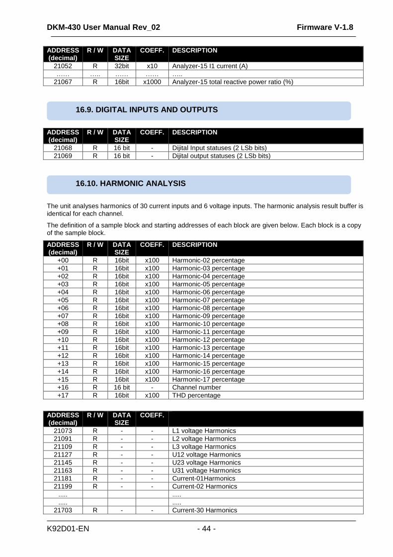
The unit analyses harmonics of 30 current inputs and 6 voltage inputs. The harmonic analysis result buffer is identical for each channel.
The definition of a sample block and starting addresses of each block are given below. Each block is a copy of the sample block.
ADDRESS (decimal)
R / W DATA SIZE
COEFF. DESCRIPTION
+00 R 16bit x100 Harmonic-02 percentage
+01 R 16bit x100 Harmonic-03 percentage
+02 R 16bit x100 Harmonic-04 percentage
+03 R 16bit x100 Harmonic-05 percentage
+04 R 16bit x100 Harmonic-06 percentage
+05 R 16bit x100 Harmonic-07 percentage
+06 R 16bit x100 Harmonic-08 percentage
+07 R 16bit x100 Harmonic-09 percentage
+08 R 16bit x100 Harmonic-10 percentage
+09 R 16bit x100 Harmonic-11 percentage
+10 R 16bit x100 Harmonic-12 percentage
+11 R 16bit x100 Harmonic-13 percentage
+12 R 16bit x100 Harmonic-14 percentage
+13 R 16bit x100 Harmonic-15 percentage
+14 R 16bit x100 Harmonic-16 percentage
+15 R 16bit x100 Harmonic-17 percentage
+16 R 16 bit - Channel number
+17 R 16bit x100 THD percentage
ADDRESS (decimal)
R / W DATA SIZE
COEFF.
21073 R - - L1 voltage Harmonics
21091 R - - L2 voltage Harmonics
21109 R - - L3 voltage Harmonics
21127 R - - U12 voltage Harmonics
21145 R - - U23 voltage Harmonics
21163 R - - U31 voltage Harmonics
21181 R - - Current-01Harmonics
21199 R - - Current-02 Harmonics
..... .....
..... .....
21703 R - - Current-30 Harmonics
16.10. HARMONIC ANALYSIS
16.9. DIGITAL INPUTS AND OUTPUTS
DKM-430 User Manual Rev_02 Firmware V-1.8
K92D01-EN - 45 -
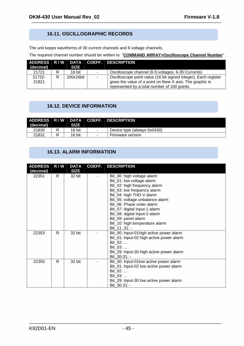
The unit kepps waveforms of 30 current channels and 6 voltage channels.
The required channel number should be written to “COMMAND ARRAY>Oscilloscope Channel Number” .
ADDRESS (decimal)
R / W DATA SIZE
COEFF. DESCRIPTION
21721 R 16 bit - Oscilloscope channel (0-5:voltages, 6-35:Currents)
21722- 21821
R 100x16bit - Oscilloscope point value (16 bit signed integer). Each register gives the value of a point on thew X axis. The graphic is represented by a total number of 100 points.
ADDRESS (decimal)
R / W DATA SIZE
COEFF. DESCRIPTION
21830 R 16 bit - Device type (always 0x0430)
21831 R 16 bit - Firmware version
ADDRESS (decimal)
R / W DATA SIZE
COEFF. DESCRIPTION
22351 R 32 bit - Bit_00: high voltage alarm Bit_01: low voltage alarm Bit_02: high frequency alarm Bit_03: low frequency alarm Bit_04: high THD-V alarm Bit_05: voltage unbalance alarm Bit_06: Phase order alarm Bit_07: digital Input-1 alarm Bit_08: digital Input-2 alarm Bit_09: panel alarm Bit_10: high temperature alarm Bit_11..31: -
22353 R 32 bit - Bit_00: Input-01high active power alarm Bit_01: Input-02 high active power alarm Bit_02: ... Bit_03: ... Bit_29: Input-30 high active power alarm Bit_30-31: -
22355 R 32 bit - Bit_00: Input-01low active power alarm Bit_01: Input-02 low active power alarm Bit_02: ... Bit_03: ... Bit_29: Input-30 low active power alarm Bit_30-31: -
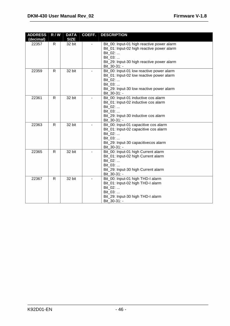
16.13. ALARM INFORMATION
16.12. DEVICE INFORMATION
16.11. OSCILLOGRAPHIC RECORDS
DKM-430 User Manual Rev_02 Firmware V-1.8
K92D01-EN - 46 -
ADDRESS (decimal)
R / W DATA SIZE
COEFF. DESCRIPTION
22357 R 32 bit - Bit_00: Input-01 high reactive power alarm Bit_01: Input-02 high reactive power alarm Bit_02: ... Bit_03: ... Bit_29: Input-30 high reactive power alarm Bit_30-31: -
22359 R 32 bit - Bit_00: Input-01 low reactive power alarm Bit_01: Input-02 low reactive power alarm Bit_02: ... Bit_03: ... Bit_29: Input-30 low reactive power alarm Bit_30-31: -
22361 R 32 bit - Bit_00: Input-01 inductive cos alarm Bit_01: Input-02 inductive cos alarm Bit_02: ... Bit_03: ... Bit_29: Input-30 inductive cos alarm Bit_30-31: -
22363 R 32 bit - Bit_00: Input-01 capacitive cos alarm Bit_01: Input-02 capacitive cos alarm Bit_02: ... Bit_03: ... Bit_29: Input-30 capacitivecos alarm Bit_30-31: -
22365 R 32 bit - Bit_00: Input-01 high Current alarm Bit_01: Input-02 high Current alarm Bit_02: ... Bit_03: ... Bit_29: Input-30 high Current alarm Bit_30-31: -
22367 R 32 bit - Bit_00: Input-01 high THD-I alarm Bit_01: Input-02 high THD-I alarm Bit_02: ... Bit_03: ... Bit_29: Input-30 high THD-I alarm Bit_30-31: -

DKM-430 User Manual Rev_02 Firmware V-1.8
K92D01-EN - 47 -
The unit conforms to the EU directives
-2006/95/EC (low voltage)
-2004/108/EC (electro-magnetic compatibility)
Norms of reference:
EN 61010 (safety requirements)
EN 61326 (EMC requirements)
The CE mark indicates that this product complies with the European requirements for safety, health
environmental and customer protection. UL / CSA Conformity:
certification testing in progress UL 508, Edition 17 UL 2200, 1st Edition. UL 840 Edition 3 CSA C22.2 NO. 14 - Edition 10
Wipe the unit, if necessary with a soft damp cloth. Do not use chemical agents
Following DIRECTIVE 2002/96/EC OF THE EUROPEAN PARLIAMENT AND OF THE COUNCIL
of 27 January 2003 on waste electrical and electronic equipment (WEEE), this unit should be stored and disposed
separately from the usual waste.
The european ROHS directive restricts and prohibits the use of some chemical materials in electronic devices.
Following the “DIRECTIVE 2011/65/EU OF THE EUROPEAN PARLIAMENT AND OF THE COUNCIL of 8 June 2011 on the restriction of the use of certain hazardous substances in electrical and electronic equipment”, this product is listed in annex-I under category: “Monitoring and control instruments including industrial monitoring and control instruments” and exempted from ROHS directive. However Datakom is not using any ROHS uncompliant electronic components in the production. Only the solder contains lead. The switching to unleaded soldering is in progress.
20. ROHS COMPLIANCE
19. DISPOSAL OF THE UNIT
DO NOT OPEN THE UNIT !
There are NO serviceable parts inside the unit.
18. MAINTENANCE
17. DECLARATION OF CONFORMITY
DKM-430 User Manual Rev_02 Firmware V-1.8
K92D01-EN - 48 -
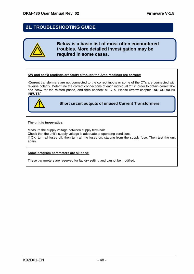
KW and cosΦ readings are faulty although the Amp readings are correct: -Current transformers are not connected to the correct inputs or some of the CTs are connected with reverse polarity. Determine the correct connections of each individual CT in order to obtain correct KW and cosΦ for the related phase, and then connect all CTs. Please review chapter “AC CURRENT INPUTS”
The unit is inoperative: Measure the supply voltage between supply terminals. Check that the unit’s supply voltage is adequate to operating conditions. If OK, turn all fuses off, then turn all the fuses on, starting from the supply fuse. Then test the unit again.
Some program parameters are skipped: These parameters are reserved for factory setting and cannot be modified.
Below is a basic list of most often encountered troubles. More detailed investigation may be required in some cases.
Short circuit outputs of unused Current Transformers.
21. TROUBLESHOOTING GUIDE