Embed Size (px)
Citation preview

DIVPRODEVINST 3120.2E
18 Jun 2021
3
Summary of Changes
Change Chapter / Para Change Summary

DIVPRODEVINST 3120.2E
18 Jun 2021
4
PAGE INTENTIONALLY BLANK
DIVPRODEVINST 3120.2E
18 Jun 2021
YP SOP Enclosure (1)
i
STANDARD OPERATING PROCEDURES
FOR YARD PATROL CRAFT
AT USNA
June 2021

DIVPRODEVINST 3120.2E
18 Jun 2021
YP SOP Enclosure (1)
ii
CONTENTS
SECTION 1 - COMMAND AND RESPONSIBILITIES
CHAPTER 1 - STANDING ORDERS
CHAPTER 2 - DUTIES AND RESPONSIBILITIES OF PERSONNEL
CHAPTER 3 - STANDARD COMMANDS
CHAPTER 4 - STANDARDS OF CONDUCT
CHAPTER 5 - OUT OF AREA OPERATIONS AND CERTIFICATION
SECTION 2 - EXECUTIVE AND ADMINISTRATION
CHAPTER 6 - SAFETY
CHAPTER 7 - CRAFT BILLS
CHAPTER 8 - LOGS AND RECORDS
CHAPTER 9 - HONORS AND CEREMONIES
CHAPTER 10 - POLLUTION CONTROL
CHAPTER 11 - FORCE PROTECTION
SECTION 3 - NAVIGATION
CHAPTER 12 - NAVIGATION STANDARDS
CHAPTER 13 - YP CHARACTERISTICS AND TACTICAL DATA
CHAPTER 14 - YP BRIDGE MANNING AND ORGANIZATION
CHAPTER 15 - DIGITAL, PAPER CHART AND PUBLICATION POLICY
CHAPTER 16 - NAVIGATION POLICY AND PROCEDURES
SECTION 4 - EQUIPMENT AND ENGINEERING
CHAPTER 17 - EQUIPMENT REQUIREMENTS
CHAPTER 18 - COMMUNICATIONS EQUIPMENT AND PROCEDURES
CHAPTER 19 - SOLAS PYROTECHNICS
CHAPTER 20 - DECK EQUIPMENT
CHAPTER 21 - DAMAGE CONTROL EQUIPMENT REQUIREMENTS
SECTION 5 - SEAMANSHIP FITTINGS AND EVOLUTIONS
CHAPTER 22 - SEAMANSHIP - ANCHORING AND TOWING
CHAPTER 23 - OPERATING WITH ROTARY WING AIRCRAFT
SECTION 6 - EMERGENCIES
CHAPTER 24 - EMERGENCY PROCEDURES
DIVPRODEVINST 3120.2E
18 Jun 2021
YP SOP Enclosure (1)
iii
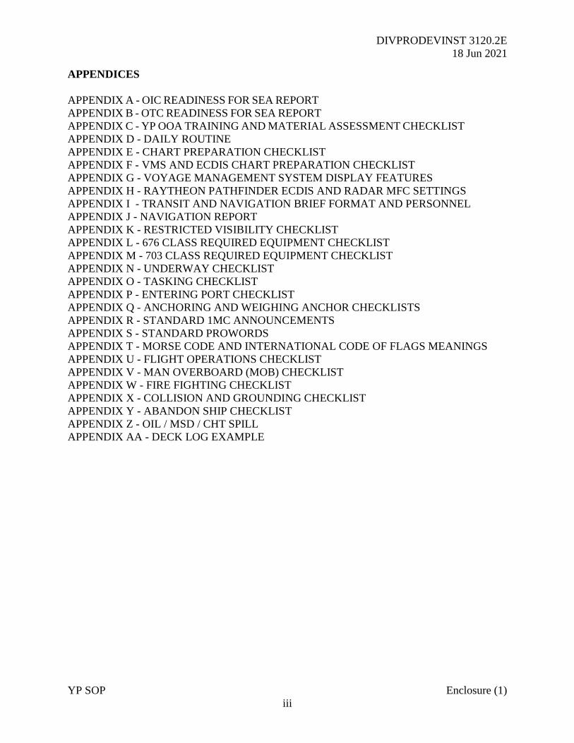
APPENDICES
APPENDIX A - OIC READINESS FOR SEA REPORT
APPENDIX B - OTC READINESS FOR SEA REPORT
APPENDIX C - YP OOA TRAINING AND MATERIAL ASSESSMENT CHECKLIST
APPENDIX D - DAILY ROUTINE
APPENDIX E - CHART PREPARATION CHECKLIST
APPENDIX F - VMS AND ECDIS CHART PREPARATION CHECKLIST
APPENDIX G - VOYAGE MANAGEMENT SYSTEM DISPLAY FEATURES
APPENDIX H - RAYTHEON PATHFINDER ECDIS AND RADAR MFC SETTINGS
APPENDIX I - TRANSIT AND NAVIGATION BRIEF FORMAT AND PERSONNEL
APPENDIX J - NAVIGATION REPORT
APPENDIX K - RESTRICTED VISIBILITY CHECKLIST
APPENDIX L - 676 CLASS REQUIRED EQUIPMENT CHECKLIST
APPENDIX M - 703 CLASS REQUIRED EQUIPMENT CHECKLIST
APPENDIX N - UNDERWAY CHECKLIST
APPENDIX O - TASKING CHECKLIST
APPENDIX P - ENTERING PORT CHECKLIST
APPENDIX Q - ANCHORING AND WEIGHING ANCHOR CHECKLISTS
APPENDIX R - STANDARD 1MC ANNOUNCEMENTS
APPENDIX S - STANDARD PROWORDS
APPENDIX T - MORSE CODE AND INTERNATIONAL CODE OF FLAGS MEANINGS
APPENDIX U - FLIGHT OPERATIONS CHECKLIST
APPENDIX V - MAN OVERBOARD (MOB) CHECKLIST
APPENDIX W - FIRE FIGHTING CHECKLIST
APPENDIX X - COLLISION AND GROUNDING CHECKLIST
APPENDIX Y - ABANDON SHIP CHECKLIST
APPENDIX Z - OIL / MSD / CHT SPILL
APPENDIX AA - DECK LOG EXAMPLE
DIVPRODEVINST 3120.2E
18 Jun 2021
YP SOP Enclosure (1)
SECTION 1
COMMAND AND RESPONSIBILITIES
DIVPRODEVINST 3120.2E
18 Jun 2021
YP SOP Enclosure (1)
1-1
CHAPTER 1
STANDING ORDERS
1-1 Command Philosophy
1-1.1 General. Being a successful mariner requires application and adherence to the following
five principles. The degree to which you and your team succeed or struggle will be directly
related to how you apply what is outlined below.
1. Preparation. How ready are you for the period underway? This preparation applies not only
to the material readiness of ship systems, but also the professional (navigation plan) and personal
measures (adequate rest, proper clothing, etc.) involved with working at sea. Have the proper
authorities reviewed the plan? Have you and your shipmates answered outstanding questions
before departure?
2. Discipline. Safety relies on the discipline to follow established checklists (MLOCs,
Checklists) and approved procedures while adhering to the guidance of supporting references.
3. Teamwork. Watch Team proficiency is essential to safety and mission delivery. The senior
leadership (Officer in Charge (OIC) and Craftmaster (CM)) must make an honest and continuous
appraisal of the professional ability of each team member. Bridge resource management is
essential, especially over sustained periods underway. Operating out of area (OOA) is a different
challenge to routine training within the Annapolis OPAREA that you should not underestimate.
Seek advice from experienced personnel as early as possible.
4. Supervision. Whenever underway for training with Midshipmen (MIDN) or under instruction
personnel (UI), an OIC, AOIC, or CM shall be in the Pilothouse to supervise the Watch Team.
The OIC is ultimately accountable for navigation, YP craft, and personnel safety.
5. Culture. The preparation effort, discipline, and teamwork you and your shipmates apply will
determine the professional culture onboard any craft, including a YP. You must conduct all
operations safely and in an effective, professional manner, reflecting the highest standards of the
Navy. Personnel must be prepared to meet the challenges, training objectives and any real
scenario head-on.
1-2 Safe Seamanship
1-2.1 General. Prudent seamanship is the mark of a Professional Mariner. OICs/CMs shall
remain aware of safe and navigable water available and the distance and time to the nearest
hazard. This situational awareness enables well-informed decisions when maneuvering. The
bridge team shall check position regularly using all available means; GPS over-reliance does not
equate to safe navigation.
1-2.2 YP Seamanship and Shiphandling Guidelines

DIVPRODEVINST 3120.2E
18 Jun 2021
YP SOP Enclosure (1)
1-2
1. An OIC, AOIC, or CM shall remain in the Pilothouse at all times when Midshipmen are
assigned control positions. When maneuvering near any pier, conducting anchorage, towing or
close approaches to another YP, a qualified OIC or CM shall stay with the Panish controls. The
OIC, AOIC, or CM may modify, delay or veto any order from a MIDN Conning Officer to
maintain craft safety.
2. Safe Speed. Every vessel shall at all times proceed at a safe speed so that they can take
proper and effective action to avoid collision and be stopped within a distance appropriate to the
prevailing circumstances and conditions. Factors to consider include traffic density, prevailing
weather conditions, engine states and limitations, performance of navigation sensors and
ECDIS/VMS, background lighting such as from shore lights or any other lights, proximity of
shoal water and accuracy of navigational charting.
3. Fight to maintain situational awareness and always know the direction to safe water.
Whenever possible, avoid pointing the bow at shoal water with any forward way on the ship.
Ensure you are maintaining a good lookout throughout by all means available, including
visually, radar and by hearing especially in restricted visibility.
4. Check your quarters before giving any rudder order. Check the rudder angle indicator after
giving the order to ensure the action taken by the helmsman is correct. Look out of the window;
is the heading changing as expected? If not, amend the order as required.
5. Momentum and basic ship Dynamics. Where possible, try to keep wash over the rudder when
maneuvering the craft, since it markedly improves shiphandling. When operating the 703 Class,
remember the importance of sustaining momentum when maneuvering at slow speeds, including
forward motion and turn rate; in marginal conditions and with a strong offsetting wind, it will
prove difficult to approach the pier. Always consider the prevailing forces of wind and currents
to determine where you will be set against the extent of safe water.
6. Use the rudder when mooring and undocking. This method teaches the best practice in a 676
class and is essential in a 703 class, especially when operating in challenging weather conditions.
7. Understand environmental factors. Wind and current have a big impact when maneuvering,
especially in confined water. Ensure you know where the wind is coming from and how it will
affect the craft, whether underway or turning at rest. Be aware of the winds effects when
approaching the pier and what are considered to be the dangerous quadrants; those where wind
direction will cause the bow or quarter to be set onto the jetty by the wind.
8. In heavy weather, think about the YP’s movement, especially if altering course across the sea
when heavy motion is expected. Consider impacts of movement on ship’s company.
9. Formation Steaming. Steaming in an ordered formation does not relieve the OIC or CM from
responsibility for contact avoidance or safe navigation. Should the lead YP or OTC establish
passing arrangements with another vessel, each YP must monitor the effectiveness of the action
until risk of collision has passed. Maneuver independently if necessary to avoid danger,
resuming station once clear.

DIVPRODEVINST 3120.2E
18 Jun 2021
YP SOP Enclosure (1)
1-3
10. If in any doubt, slow or stop the craft. Slowing or stopping will allow more time to assess
the situation and avoid any danger. However, before doing so consider any vessels directly
astern, especially if formation steaming. Additionally, consider the dangers associated with
areas of significant tidal stream. Currents have a far greater effect on craft at slow speeds.
1-3 Contact Management. The OIC and CM must always ensure the YP is safe for navigation
and safe from shipping.
1-3.1 Contact Management Tools
1. Bearing Drift. The most effective way to determine risk of collision is to take a visual
bearing of the contact and monitor bearing drift over a period of at least one minute. Constant
Bearing Decreasing Range (CBDR) is an indication a risk of collision exists.
2. Radar. Radars fitted to each class of YP have Automated Radar Plotting Aid (ARPA)
capability. Configuring the display with relative vectors will show how targets move relative to
the YP. However, the system will take an amount of time from contact detection to determine an
accurate closest point of approach (CPA). Therefore, the bridge team should carefully monitor
contacts until finally past and clear. True trials will accurately show any alteration of the contact
and allow the operator to determine if the target is following a set channel or traffic route.
3. Maneuvering Boards (MOBOARDS). Bridge teams shall use MOBOARDs for both training
purposes and contact avoidance. Do not allow plotting a solution to distract from the primary
focus of safe navigation.
1-3.3 Contact Management Guidelines
1. All OICs, AOICs and CMs shall maintain a good working knowledge of the Inland and
International Rules of the Road. Any maneuver must be in accordance with the Rules. Planned
speed should enable taking proper, effective and seaman like action to avoid collision.
2. Take early action and make your intentions clear to other vessels. Transmit AIS throughout
and make effective use of VHF radio to resolve any concerns. Where appropriate, make proper
use of sound signals with the ship’s whistle.
3. If you find yourself in such close quarters with another vessel and risk of collision exists
consider the following actions:
a. Turn away from the other vessel, preferably to starboard if the situation permits.
b. Avoid crossing ahead of another vessel at close quarters.
c. Slow down, reducing the relative closure rate.
d. Stop the craft.
DIVPRODEVINST 3120.2E
18 Jun 2021
YP SOP Enclosure (1)
1-4
e. Sound 5 short blasts.
1-3.4 Merchant Vessel (MV) Contact Avoidance Guidance
1. Large MVs often operate with reduced manning on the bridge. Merchant Mariners are
experienced deck officers who routinely manage CPAs considerably closer than a YP would
wish to have with a training crew of midshipmen embarked. Early communication can resolve
such situations. Make best use of all of your navigation sensors including AIS and radar. When
possible, use the Vessel’s name over VHF radio rather than just a geographical position.
2. For large, less maneuverable contacts such as supertankers, VLCCs or Aircraft Carriers, apply
the 3-2-1 rule. That is, do not pass not within 3nm shear, 2nm abeam or 1nm astern. Remember
that such vessels have a considerable shadow zone and although their bridge enjoys a significant
height of eye advantage, they will often fail to see a small contact up to 4,000 yards ahead of the
bow.
1-3.5 Contact Reporting. The Officer of the Deck (OOD), which may be MIDN or other
personnel Under Instruction, shall report all surface contacts with a CPA of 4,000 yards or less to
the OIC/AOIC or CM on-watch before they reach 6,000 yards using the standard reporting
format shown below. The OIC is to be informed of any contact with a CPA of less than 2,000
yards.
YP CONTACT REPORT FORMAT
“OIC/AOIC/CM. The time is _________. This is _____________ with a contact report.
The contact is a _____________________ (Example: merchant vessel, sailboat, pleasure craft).
The contact bears ________ DEGREES relative at a range of ________ YARDS/MILES.
The target angle is ________ DEGREES.
The contact has SLOW / FAST LEFT / RIGHT bearing drift.
The contact will CPA my PORT/STARBOARD BEAM/BOW
in ________ MINUTES at a range of ________ YARDS/MILES.
I intend to MAINTAIN / ALTER course and speed to ________.”
DIVPRODEVINST 3120.2E
18 Jun 2021
YP SOP Enclosure (1)
1-5
1-4 Weather
1-4.1 General. A thorough understanding of both actual and forecasted weather and tidal
conditions is vital to safe YP operation underway. The operation order (OPORD) for all OOA
deployments will specifically detail supporting weather products available to all OICs, AOICs,
and CMs. Open source resources should also be consulted prior to routine operations.
1-4.2 Weather Factors. The normal atmospheric pressure at sea level is 29.92 inHg (1113.25
millibars). Knowing the ambient pressure reading prior to getting underway is essential to
noticing any change. Reducing barometric pressure is an indication of worsening weather the
severity of which depends on the pressure difference between high and low systems. Rising
pressure therefore means the reverse. Dew point reading (available in the 703 class only) is an
indicator of potential fog, the risk of which is elevated when air temperature is within 4°F of the
dew point.
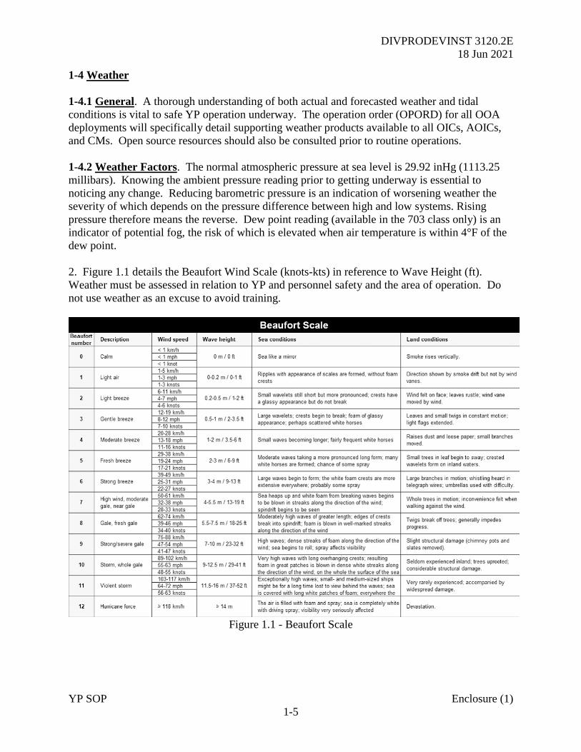
2. Figure 1.1 details the Beaufort Wind Scale (knots-kts) in reference to Wave Height (ft).
Weather must be assessed in relation to YP and personnel safety and the area of operation. Do
not use weather as an excuse to avoid training.
Figure 1.1 - Beaufort Scale
DIVPRODEVINST 3120.2E
18 Jun 2021
YP SOP Enclosure (1)
1-6
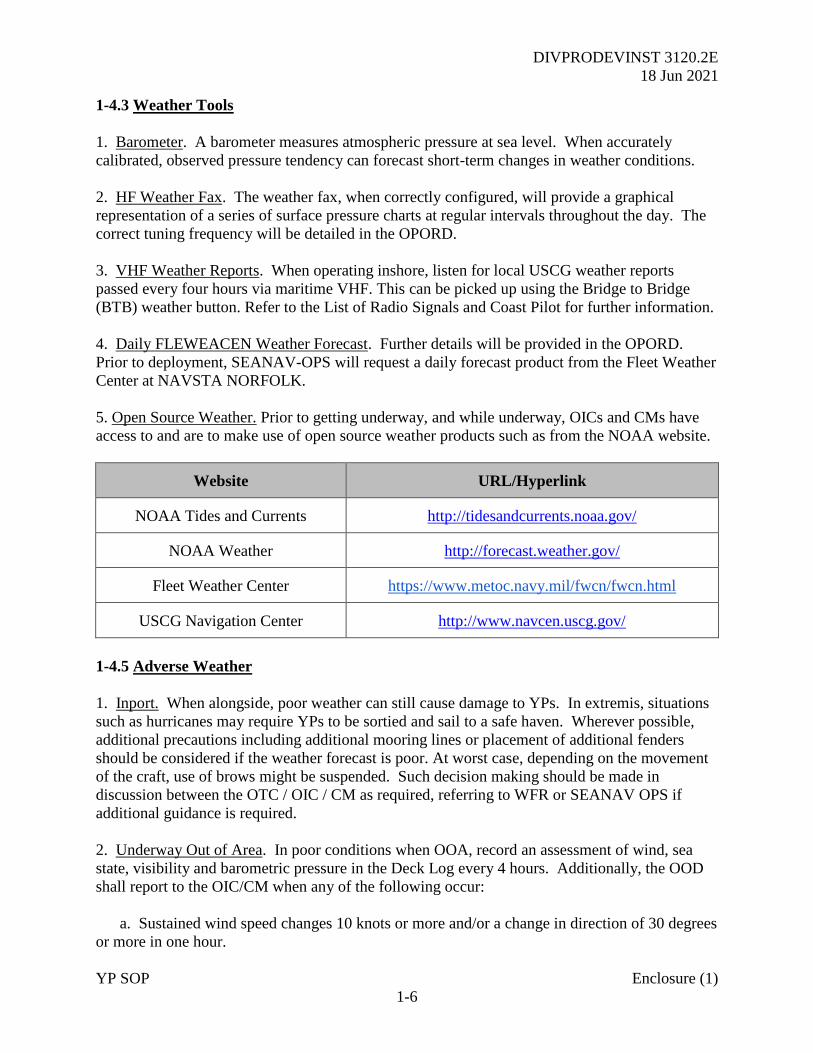
1-4.3 Weather Tools
1. Barometer. A barometer measures atmospheric pressure at sea level. When accurately
calibrated, observed pressure tendency can forecast short-term changes in weather conditions.
2. HF Weather Fax. The weather fax, when correctly configured, will provide a graphical
representation of a series of surface pressure charts at regular intervals throughout the day. The
correct tuning frequency will be detailed in the OPORD.
3. VHF Weather Reports. When operating inshore, listen for local USCG weather reports
passed every four hours via maritime VHF. This can be picked up using the Bridge to Bridge
(BTB) weather button. Refer to the List of Radio Signals and Coast Pilot for further information.
4. Daily FLEWEACEN Weather Forecast. Further details will be provided in the OPORD.
Prior to deployment, SEANAV-OPS will request a daily forecast product from the Fleet Weather
Center at NAVSTA NORFOLK.
5. Open Source Weather. Prior to getting underway, and while underway, OICs and CMs have
access to and are to make use of open source weather products such as from the NOAA website.
Website URL/Hyperlink
NOAA Tides and Currents http://tidesandcurrents.noaa.gov/
NOAA Weather http://forecast.weather.gov/
Fleet Weather Center https://www.metoc.navy.mil/fwcn/fwcn.html
USCG Navigation Center http://www.navcen.uscg.gov/
1-4.5 Adverse Weather
1. Inport. When alongside, poor weather can still cause damage to YPs. In extremis, situations
such as hurricanes may require YPs to be sortied and sail to a safe haven. Wherever possible,
additional precautions including additional mooring lines or placement of additional fenders
should be considered if the weather forecast is poor. At worst case, depending on the movement
of the craft, use of brows might be suspended. Such decision making should be made in
discussion between the OTC / OIC / CM as required, referring to WFR or SEANAV OPS if
additional guidance is required.
2. Underway Out of Area. In poor conditions when OOA, record an assessment of wind, sea
state, visibility and barometric pressure in the Deck Log every 4 hours. Additionally, the OOD
shall report to the OIC/CM when any of the following occur:
a. Sustained wind speed changes 10 knots or more and/or a change in direction of 30 degrees
or more in one hour.
DIVPRODEVINST 3120.2E
18 Jun 2021
YP SOP Enclosure (1)
1-7
b. Visible changes in sea height and direction.
c. Barometric pressure at or below 29.7 inches, with a change in barometric pressure of 0.04
inches in one hour or 0.10 inches in a four hour period.
d. Dew point is within 5°F of dry bulb temperature (YP 703 class only).
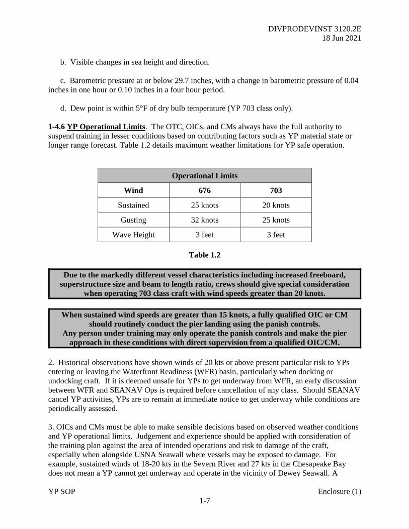
1-4.6 YP Operational Limits. The OTC, OICs, and CMs always have the full authority to
suspend training in lesser conditions based on contributing factors such as YP material state or
longer range forecast. Table 1.2 details maximum weather limitations for YP safe operation.
Operational Limits
Wind 676 703
Sustained 25 knots 20 knots
Gusting 32 knots 25 knots
Wave Height 3 feet 3 feet
Table 1.2
Due to the markedly different vessel characteristics including increased freeboard,
superstructure size and beam to length ratio, crews should give special consideration
when operating 703 class craft with wind speeds greater than 20 knots.
When sustained wind speeds are greater than 15 knots, a fully qualified OIC or CM
should routinely conduct the pier landing using the panish controls.
Any person under training may only operate the panish controls and make the pier
approach in these conditions with direct supervision from a qualified OIC/CM.
2. Historical observations have shown winds of 20 kts or above present particular risk to YPs
entering or leaving the Waterfront Readiness (WFR) basin, particularly when docking or
undocking craft. If it is deemed unsafe for YPs to get underway from WFR, an early discussion
between WFR and SEANAV Ops is required before cancellation of any class. Should SEANAV
cancel YP activities, YPs are to remain at immediate notice to get underway while conditions are
periodically assessed.
3. OICs and CMs must be able to make sensible decisions based on observed weather conditions
and YP operational limits. Judgement and experience should be applied with consideration of
the training plan against the area of intended operations and risk to damage of the craft,
especially when alongside USNA Seawall where vessels may be exposed to damage. For
example, sustained winds of 18-20 kts in the Severn River and 27 kts in the Chesapeake Bay
does not mean a YP cannot get underway and operate in the vicinity of Dewey Seawall. A
DIVPRODEVINST 3120.2E
18 Jun 2021
YP SOP Enclosure (1)
1-8
discussion and an agreement between the OIC and CM are needed to assess safety and to
maximize training.
4. While SEANAV may decide to conduct alternative training or otherwise cancel the activity,
that decision should only apply to the task in progress. SEANAV will decide on proceeding with
the next scheduled task no later than one hour prior to start time. WFR and SEANAV Ops will
consider dangers of berthing at WFR Basin during such discussions.
5. If underway, conditions worsen outside of the limitations described, the OIC and CM shall
discuss whether to continue training. If they decide to continue training, the OIC and CM shall
continue to assess the situation at the end of each period of instruction. If they determine they
cannot conduct training safely, they shall return the YP immediately alongside.
6. Alternative training may include fixing underway in the Severn River, shiphandling in the
vicinity of Dewey Seawall, or training pierside. The OIC and CM shall include this discussion
as part of the navigation brief prior to getting underway.
7. The OIC and CM shall maximize training opportunities whenever possible. If they decide to
cancel operations based on local weather conditions, they shall inform WFR and SEANAV OPS.
8. When the Instructor is not OIC qualified, the authority to decide to continue training remains
with the CM as the senior qualified individual. If there is disagreement, the Instructor and CM
shall raise the issue to SEANAV and WFR OPS on completion of the training evolution.
1-5 Required Reports
1. General. The following is a list of required reports to be made to the OIC/AOIC or CM on-
watch at any given time:
a. Routine
(1) All occurrences the OOD feels are worthy of note, especially those with implications
on the safety of the YP and embarked personnel.
(2) Any failure to properly decode tactical signals or intentions passed by another craft
when steaming in Formation.
b. Emergencies
(1) When in any doubt or when a possible emergency situation is developing.
(2) When taking necessary action in an emergency to avoid collision, grounding or other
danger. Pass a Flash Report to the OTC immediately after taking initial action. Request
assistance and await further instruction as appropriate.
DIVPRODEVINST 3120.2E
18 Jun 2021
YP SOP Enclosure (1)
1-9
(3) On sighting any other vessel or craft in distress, or on receipt of a radio distress call.
Only answer distress calls with the explicit approval of the OIC.
(4) Any accidents or injury to embarked personnel.
(5) Any potentially dangerous, unusual or important sighting such as breakers, unlighted
or derelict vessels, floating debris, discolored water, audible or visible emergency/distress
signals, waterspouts or any occurrence deemed out of the ordinary.
c. Navigation. All reports in accordance with YP Navigation Standards.
d. Equipment and Material Status. Report any degradations or equipment loss which may
affect YP safety or could have an adverse effect on planned operational and training objectives.
Further, any anticipated change to ship’s systems that affect crew habitability.
e. Summary of Reports to the OIC
(1) Vessel Contact Reports (CPA < 2000 yards).
(2) Receipt of any Tactical Signal.
(3) Sighting any Warship, Auxiliary or Military Aircraft.
(4) On observing a marked change in the Weather, or on receipt of a weather warning.
(5) Receipt of any Distress Call.
(6) Major change of engineering plant status.
(7) On any change of watch team readiness.
(8) On any marked increase in traffic density.
(9) If entering an area of restricted visibility.
(10) If dragging Anchor.
(11) If unable to maintain assigned Station.
(12) Sunset.
(13) On making landfall, or on failure to sight land as expected.
(14) If unable to fix the position of the craft, or on loss of GPS or ECDIS/VMS.
(15) If unable to maintain track (XTD > 2000 yards) and required PIM.
DIVPRODEVINST 3120.2E
18 Jun 2021
YP SOP Enclosure (1)
1-10
(16) Any change in Watertight Integrity, including operating single valve to sea systems.
(17) Any Emergency onboard the craft or other vessels in company.
(18) When in any doubt.
1-6 Conduct of the Watch
1. General. Ensuring effective bridge resource management and sustaining the proficiency of
the watch team is the responsibility of the senior personnel in the Pilothouse (OIC/AOIC/CM).
2. Safety. Safety shall always be the primary consideration, especially in heavy weather. Ensure
warnings are given over 1MC circuits if anticipating heavy rolls or heels. If it is dangerous for
personnel to go topside (weather, signal decks, or fantail), the OIC shall restrict such access with
announcements over the 1MC every half hour. When imperative to go topside, take all required
and prudent precautions, including but not limited to:
a. Obtain permission from the OIC.
b. Use the “Buddy” system.
c. Wearing a serviceable life preserver and tended safety lines.
d. If possible, alter course and speed to reduce the effect of the adverse conditions.
e. Ensure competent supervision (Officer or Senior Enlisted).
f. Conduct a tailored safety brief prior to execution.
3. It is essential to maintain professionalism on the bridge. Address one another by watch title
and ensure personnel remain alert and maintain a proper lookout at all times, including having
serviceable binoculars for the Lookouts, Conn, and OOD.
4. Relationship with the Watch in Engineering Operating Station (EOS). The EOS watch is
responsible for safe and proper operation of YP propulsion, electrical, and auxiliary systems.
The watch station must operate the engineering plant in accordance with good engineering
practices and strict adherence to specific operating procedures. The Chief Engineer is required
to report to the OIC and CM any changes in equipment condition or in the event of any casualty.
5. Prior to Relieving the Watch. The OIC, AOIC, CM, OOD, and CONN shall conduct a full
and proper handover. The acronym NOCWIS is a useful guide to covering all essential items.
a. Navigation. Conduct a check fix. Study the navigation plan and review the track for the
watch duration. This should include speed requirements and any areas of particular caution, such
as approaches to harbor limits, speed restrictions, reporting points, etc.
DIVPRODEVINST 3120.2E
18 Jun 2021
YP SOP Enclosure (1)
1-11
b. Operations. Review the Schedule of Events for the period of the watch, including a review
of the Tactical Signals Log when in company. Consider which craft is acting as the Guide and
who is the OCE. Know what formation or screen in which the YPs are steaming, and what
signals are awaiting execution.
c. Communications. Ensure familiarity with all applicable VHF / UHF / HF circuits,
including call signs.
d. Weather. Review actual and forecasted weather conditions with off-going OIC/CM.
e. Internal. Have knowledge of the engineering plant state and any limitations in place.
Know if any equipment is running near or outside of the set parameters or if any major
equipment is out of commission and the estimated time of repair.
f. Ensure all appropriate lights, shapes, and other signals are correctly displayed.
g. Understand restrictions, including access to the upper deck.
h. Shipping. Review surface and radar plot with specific attention to any contacts being
tracked including range, bearing, CPA, and TCPA.
5. Pattern of Relieving the Watch. Watches will be relieved in accordance with the schedule
below. Promptness in reporting to relieve a watch is professional courtesy. Times to relieve will
vary dependent on prevailing operational circumstances detailed in the SOE. No one is to take a
watch until they are comfortable with the situation and have all the information required to
conduct a safe watch. Do not relieve the watch during complex maneuvers; the OIC will amend
the turnover time accordingly.
a. EOS – 1/2 hour before the hour.
b. Midshipman Navigator – 15 minutes before the hour.
c. OOD – on the hour.
6. OICs, AOICs and CMs shall ensure Watchstanders are appropriately clothed for weather
conditions before assuming the watch.
7. Relieving the Watch. When relieving the watch, you shall:
a. Make certain you are well rested, appropriately clothed, equipped for heavy weather (if
required), and have adequate night vision to stand an alert watch.
b. Have at least four hours of sleep prior to watches between 0001 to 0600.
c. If you become ill, you must notify the OIC/CM immediately.
DIVPRODEVINST 3120.2E
18 Jun 2021
YP SOP Enclosure (1)
1-12
d. Any change to the watch standing assignments must be approved by the OIC.
8. Watch Relief Procedure. All personnel will follow the below watch relief procedure:
• Relieving Officer: (Salute) “I AM READY TO RELIEVE YOU, SIR/MA’AM.”
• Conning Officer: (Return Salute) “I AM READY TO BE RELIEVED.”
• Conduct turnover brief above.
• Relieving Officer: (Salute) “I RELIEVE YOU, SIR/MA’AM.”
• Relieved Officer: (Return Salute) “I STAND RELIEVED. THIS IS MIDSHIPMAN X,
MIDSHIPMAN Y HAS THE CONN/DECK.”
• Conning/Deck Officer: “IN THE PILOT HOUSE, THIS IS MIDSHIPMAN
Y, I HAVE THE CONN/DECK.”
DIVPRODEVINST 3120.2E
18 Jun 2021
YP SOP Enclosure (1)
2-1
CHAPTER 2
DUTIES AND RESPONSIBILITIES OF PERSONNEL
2-1 Officers and Craftmasters
2-1.1 Officer in Tactical Command (OTC)
1. Any officer acting as OTC for a Squadron or as the OIC of a single YP operating alone shall:
a. Have overall responsibility for the safety, planning, training, and conduct of all
participating Midshipmen and Staff.
b. The OTC shall read and abide by all instructions detailed in the OPORD.
c. Review all navigation charts and digital voyage plans of each pennant, ensuring all OICs
within the squadron formally approve and sign all charts for their individual craft.
d. Ensure the Squadron follows the approved training schedule and SOE detailed in the
OPORD. The OTC is authorized to make changes to the SOE if operational necessity dictates
but should normally communicate such changes to the SEANAV Chairman via OPS.
e. Ensure a transit brief is conducted with all OICs and CMs in accordance with the
navigation standards detailed in Chapter 12 no less than 24 hours prior to proceeding underway.
f. Once underway, monitor the conduct of navigation of all Squadron vessels,
communicating early if a maneuver or position appears erroneous or unsafe.
g. Liaise with OPS to ensure the USNA Chain of Command remains informed throughout
the underway period.
h. Seek advice from SEANAV when in any doubt and additionally as detailed below:
(1) Provide a daily SITREP while underway, to be routed via the Operations Officer.
(2) In the event of any casualty to equipment or personnel, the OTC is to attempt to
contact SEANAV via cellular or satellite telephone. If there is no coverage at the time of the
emergency, make use of VHF and HF radio circuits to relay an urgent message via the U.S.
Coast Guard.
DIVPRODEVINST 3120.2E
18 Jun 2021
YP SOP Enclosure (1)
2-2
2-1.2 Officer in Charge (OIC)
1. An OIC shall be qualified in accordance with the DIVPRODEVINST 3511.1 series. When an
officer embarks a YP for local area operation training, they may sign on to the Ship as OIC in the
Deck Log. If not, they are considered to be an Instructor as defined at paragraph 2-1.5. The OIC
shall:
a. Be responsible for safety, training, and conduct of all midshipmen embarked.
b. Read and abide by all SOP and Operations Order instructions.
c. Before getting underway:
(1) Formally assume responsibility for their YP by a notation in the deck log.
(2) Review, approve, and sign all charts for their individual pennant. Digital charts and
setup shall also be reviewed and approved by each OIC.
(3) Verify the Engineering Master Pre-Light off Checklist (MLOC) is complete and
properly annotated in the deck log. If MLOCs are not complete, the OIC and CM shall postpone
the underway period until the checks are correctly completed.
d. When underway:
(1) Adhere to and enforce the required navigation standards.
(2) Verify navigational position by at least two means (visual, radar, GPS). The OIC is
ultimately charged with responsibility as Navigator when embarked.
(3) If safe navigation is in question, the OIC is to immediately take control of the YP and
suspend training. Once the situation is resolved, the OIC may resume training.
(4) Take control of the YP’s engines and rudder as required if the actions of the MIDN
watch team are not sufficient to prevent entering dangerous waters.
e. Make reports to the OTC on any issues regarding the material state of vessel, conduct
offenses, issues affecting ability to train midshipmen, or when in any doubt about safety or what
other action is required of their craft.
f. When underway, shall establish clear divisions of responsibility with the CM to ensure
that all roles are fulfilled and to avoid confusion, especially during Local Area operations.

DIVPRODEVINST 3120.2E
18 Jun 2021
YP SOP Enclosure (1)
2-3
2-1.3 Assistant Officer in Charge (AOIC)
1. The AOIC shall:
a. Support the OIC and CM to ensure position is known at all times by utilizing at least two
sources of information (visual, radar, GPS).
b. Support the OIC in the training of midshipmen and ensure they are able to sustain safe
navigation.
c. If safe navigation is in question, take control of the YP and suspend training until the OIC
approves resuming training.
d. Take control of the YP’s engines and rudder as required if the actions of the midshipmen
watch team are not sufficient to prevent entering dangerous waters.
2-1.4 Craftmasters (CM)
1. The CM shall:
a. If an OIC is not embarked, the CM shall assume the full responsibility for safety of the YP
and all embarked personnel.
b. Supervise the training of midshipmen.
c. If the safe navigation of the YP is in question, immediately take control of the YP and
suspend training until the OIC approves resuming training.
d. Take control of the YP’s engines and rudder as required if the actions of the MIDN watch
team are not sufficient to prevent entering dangerous waters.
e. In addition to the OTC’s daily SITREP, the Senior CM shall liaise directly with the WFR
Director and Senior CM to arrange any additional engineering support and provide an update on
consumables, liquid states, and any emerging Enlisted personnel issues.
2-1.5 Instructors
1. Instructors are deemed to be Officers, Enlisted or civilian personnel who are assigned to
USNA for teaching purposes. Where that teaching involves midshipmen instruction underway,
Staff Instructors will aim to complete the OIC qualification process. However, if not OIC
qualified, they shall complete the Underway Instruction training and endorsement in accordance
with the SEANAVINST 3530.1 series. When not OIC qualified, the CM remains fully
responsible for YP, personnel safety, and the decisions associated with operating underway.
2. Prior to any underway training evolution, it is imperative that the instructor and CM discuss
training objectives, roles, and responsibilities. For training objectives that allow the instructor to
DIVPRODEVINST 3120.2E
18 Jun 2021
YP SOP Enclosure (1)
2-4
maintain full situational awareness of shipping and navigation and if the instructor is OIC
qualified, they will sign for responsibility of craft in the deck log and the CM will provide
forceful backup to the instructor.
3. For specific training evolutions where the instructor’s attention is focused on training and does
not allow the instructor to act as a proper look-out and safety or if the instructor is not OIC
qualified, the CM will maintain responsibility for the craft. If the instructor is a qualified OIC or
a previous Officer of the Deck (Underway), they will provide forceful backup to the CM should
it not interfere with the training objectives.
2-1.6 Chief Engineer (CHENG)
1. The enlisted engineer (second class petty officer or above) is responsible to the OIC/CM for
the complete readiness, maintenance, and operation of all engineering systems onboard. This
includes propulsion, electrical generation, ventilation, and all other hotel services including
MSD/CHT. Additional specialist personnel, such as an ET, shall embark when travelling OOA.
2-1.7 Relationships
1. Upon embarking, officers shall inform the CM of their qualification level. The CM shall brief
any existing material discrepancies and Temporary Standing Orders (TSOs). If OIC qualified
Officers assume responsibility for the vessel, make a Deck Log entry.
2. All OICs shall give due regard to the advice and recommendations of the CM. The CM’s
acquired rank, rating, and qualifications are further enhanced by the experience of daily handling
of the YP. CMs shall provide forceful back up to the OIC whenever they believe the vessel is in
danger. If the OIC does not concur with the recommendation, the CM may enter it into the Deck
Log. Any such conflict must immediately be brought to the attention of the OTC when OOA or
the SEANAV and WFR OPS when conducting local operations.
3. Prior to commencing any event, the OIC shall brief the CM regarding training intentions and
equipment requirements. The CM and crew shall assist in the conduct of the serial as directed by
the OIC, but shall be permitted to conduct routine ship’s work if not required.
2-2 Midshipmen Billets. The OIC may assign Midshipmen to any of the following roles when
the YP is deployed out of the Annapolis OPAREA, during summer training, or for any YPRON
MO.
2-2.1 Midshipman Commanding Officer (MCO)
1. The MCO shall act as the Pennant CO in the execution of any planned training serial.
2. Any midshipman who has demonstrated outstanding performance during Atlantic
Professional Afloat Training (LANTPAT) or routine YPRON Operations may pursue the award
of the midshipmen OIC pin. Further detail is included in reference (h).
DIVPRODEVINST 3120.2E
18 Jun 2021
YP SOP Enclosure (1)
2-5
2-2.2 Executive Officer (MXO)
1. The MXO shall be responsible under the MCO for the following tasks:
a. The cleanliness of the YP, which is subject to daily inspections.
b. Preparation, distribution, and coordination of the SOE and Plan of the Day (POD).
c. Food preparation and oversight of galley operations.
2-3 Underway Watch Organization. Watch team proficiency is a key element of the OOA
Assessment required before departing the Annapolis OPAREA. To maximize training benefit,
midshipmen should be rotated through each watch position. However, in the event of a marked
traffic increase or on entering pilotage waters, personnel should revert to the position assessed in.
2-3.1 Watchstanders
1. Officer Conducting Exercise (OCE). The OTC may assign an OIC as the OCE for the
duration of a pre-planned serial such as DIVTACS.
2. Officer of the Deck (OOD). The designated OOD is in charge of all personnel on watch. This
will normally be a Midshipman or Staff Instructor Under Instruction during Movement Orders
(MO).
3. Conning Officer (Conn). The Conn, under the supervision of the OOD, is charged with
issuing the necessary orders to helm and lee helm to steer the ship as required. A good working
relationship between the Conn and Navigation Team is essential.
4. Assistant Navigator (ANAV). The ANAV is responsible for maintaining accurate and regular
fixing of the ship under supervision of the OIC/CM. All means available are to be used to
accurately predict future movement, providing timely reports to the Conning Team.
5. Plotter. Works under the supervision of the ANAV to accomplish the following tasks:
a. Plot the fix using appropriate symbology and 4-digit time labels.
b. Calculate an accurate DR position to twice the duration of the fix interval, whilst
following the rules of DR.
c. When able, calculate set and drift.
d. Determine distance off track and calculate distance and time to the next turn.
e. Always check the depth sounding against every fix position.
f. Immediately notify the ANAV if unable to plot a fix for any reason.
DIVPRODEVINST 3120.2E
18 Jun 2021
YP SOP Enclosure (1)
2-6
6. Bearing Book (BB) Recorder. Assists the ANAV as detailed below:
a. Maintain communications with the bridge wing Bearing Takers and relay timely
information to the Plotter as directed.
b. Maintain the Bearing Book with the following information.
(1) Time of each fix.
(2) Bearings to visual navigation aids.
(3) Ranges to radar navigation aids.
(4) Any GPS position plotted.
(5) Soundings at each fix.
c. Act as the timekeeper, prompting each bearing taker for a fix.
7. Bearing Taker/Lookout(s). Assist the BB Recorder as detailed below:
a. Maintain a good lookout for other shipping contacts and any opening navigations aids.
b. Report bearings to the BB Recorder and advise when available navigation aids have been
gained and lost.
c. Report to the BB Recorder when passing significant navigation aids such as buoys or
beacons at close range.
8. Radar Operator. Provides the following service to the Navigation Team:
a. Obtain accurate radar ranges to navigation aids designated by the Navigator.
b. Support the OOD in Collision Avoidance, tracking surface contacts using ARPA.
9. Helmsman and Lee Helmsmen. Nominated watchstanders must have the basic proficiency
required to operate respective controls.
10. Engineering Operating Station (EOS) Watch. Under the close supervision of the YP
Engineer, this midshipman shall complete the following duties:
a. Ensure all OOD’s orders are promptly acknowledged and executed when in EOT.
b. Immediately report any equipment casualty to the bridge. To avoid confusion, the
CHENG is to report all losses of propulsion, steering, or when any fire danger exists.
DIVPRODEVINST 3120.2E
18 Jun 2021
YP SOP Enclosure (1)
2-7
c. Ensure access to the engine room is controlled.
d. Ensure all required instrumentation readings are recorded as directed by the CHENG.
11. Digital Navigation Procedures. YPs are not digitally certified as the primary means of
navigation as the equipment does not meet ECDIS-N standards or the US Navy Operations
Instructions training standards. However, for training purposes and real time craft safety, the
ECDIS-N Voyage Management System in the 676 Class and Raytheon Pathfinder ECDIS in the
703 Class may be used as the primary navigation plot provided correct paper charting is held on
board. In this case, a Plotter and BB Recorder are not required. However, should there be a loss
of system capability or GPS, craft are to resort immediately to paper navigation as the primary
plot with additional personnel manned in order to support the increased frequency of fixing
required to manage dead reckoning. If there is any doubt, the bridge team shall return full
navigation to paper charting.
2-4 Inport Duty Sections
1. Qualified officers and enlisted personnel deployed with YPs are charged with ensuring the
safety of the craft and embarked personnel inport. The duty section shall meet the following
personnel requirements at all times, allowing the OIC/CM to deal with any emergency that may
occur:
a. A fully type qualified OIC or CM shall be onboard each YP at all times. If two or more
YPs are deployed together, one craft shall have a CM the other(s) an OIC. At the OTC’s
discretion, this requirement may be relaxed to one CM or OIC per nest.
b. One fully type qualified Engineer is required if the craft is not connected to stable shore
power and the auxiliary generator is running. At the OTC’s discretion, this requirement may be
relaxed to one Engineer per grouping (or nest) of craft.
c. Two other persons (to include officers or enlisted crew who may be U/I) who are able to
support the OIC/CM and Engineer, bringing the minimum number onboard at any one time to
three. The crew may draw these two additional personnel from junior enlisted Sailors assigned
to the craft from WFR, or any senior enlisted or officer trainee embarked. These personnel must
be able to fight a fire and support the Duty Section in event of an emergency.
2. The OPORD shall detail inport duty sections.
3. Midshipmen shall primarily maintain an alongside duty section for training. The OIC shall
assign the following positions:
a. Midshipman Command Duty Officer (MCDO), to assist the OIC/CM as directed.

DIVPRODEVINST 3120.2E
18 Jun 2021
YP SOP Enclosure (1)
2-8
b. Officer of the Deck (Inport OOD). To maintain the quarterdeck watch and control access
over the gangway. The duty section shall rotate this post at least every four hours and make
adequate provisions during periods of extreme weather.
DIVPRODEVINST 3120.2E
18 Jun 2021
YP SOP Enclosure (1)
3-1
CHAPTER 3
STANDARD COMMANDS
3-1.1 Introduction. The use of standard phraseology for giving commands to the lee helmsman
and helmsman will ensure that the response will be immediate because of their familiarity with
the format of the commands. It is essential the Conning Officer be precise with the use of
standard commands and reports. Reference (e) is an excellent resource for studying standardized
commands, and all bridge watchstanders should be familiar with its contents.
2. Standard commands given on the bridge of a ship follow the strictest sequence at all times.
The Conning Officer will give the command to the helmsman or lee helmsman in the proper
format. The watchstander then repeats back this order to the Conning Officer. Once the
watchstander has carried out the command, he or she reports completion of the action to the
Conning Officer. The Conning Officer acknowledges completion of the order by responding
“Very Well.”
3-2 Commands to the Lee Helmsman
1. The format of commands is to be the desired engine followed by the direction the engine is to
be engaged and the speed to be ordered.
ENGINE: “Port Engine”, “Starboard Engine”, “All Engines”.
DIRECTION: “Ahead”, “Back”.
SPEED: “One-third”, “Two-thirds”, “Standard”, “Full”.
May be followed by: “Indicate ____ RPMs for ___ knots” (ahead speeds);
“One-third”, “Two-thirds”, “Full”
(for astern speeds, there are no revolutions given for astern speeds).
2. When shifting an engine’s direction, first order the engine to “Stop” and then to the desired
direction in order to prevent inadvertent shutdown of an engine on a YP 703 class.
3. When conducting precise maneuvering on a YP 703 class, using the phrase “in-the-box,”
following a one-third engine command, directs the lee helmsman to set the throttle inside the
“stop” box of the throttle. This adjustment results in a lower RPM setting needed for finesse pier
work.
DIVPRODEVINST 3120.2E
18 Jun 2021
YP SOP Enclosure (1)
3-2
3-3 Commands to the Helmsman
1. Before executing any rudder order, the Conning Officer must look in the direction of the
intended turn to verify that it is safe to make the turn. The Radar Operator can also assess
whether the new course is clear of shipping or any other hazard. Once a rudder order is
executed, the Conning Officer must monitor the situation by checking the rudder angle indicator
to ensure that the rudder was put over in the correct direction to make certain the command is
correctly carried out. If the heading fails to change as expected, the Conning Officer shall
modify the order.
2. Commands to the helmsman are always given in the same format, with the desired direction
followed by the amount of rudder.
DIRECTION: “Left”, “Right”.
AMOUNT: “Number of degrees”, “Standard”, or “Full”.
3. A course to steer is normally given following the rudder command to the helmsman. The
following example shows the sequence of standard commands and responses:
Conning Officer: “Right 10 degrees rudder, steady on course 150.”
Helmsman: “Right 10 degrees rudder steady on course 150, aye, Sir/Ma’am.”
Helmsman: (when the rudder is right 10 degrees) “My rudder is right 10
degrees, coming to course 150, Sir/Ma’am.
Conning Officer: “Very Well.”
Helmsman: “Steady on course 150, Sir/Ma’am.”
Conning Officer: “Very Well.”
DIVPRODEVINST 3120.2E
18 Jun 2021
YP SOP Enclosure (1)
3-3
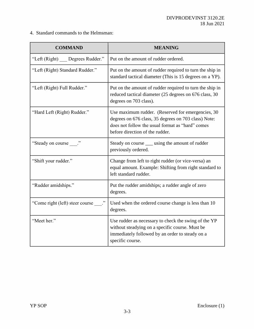
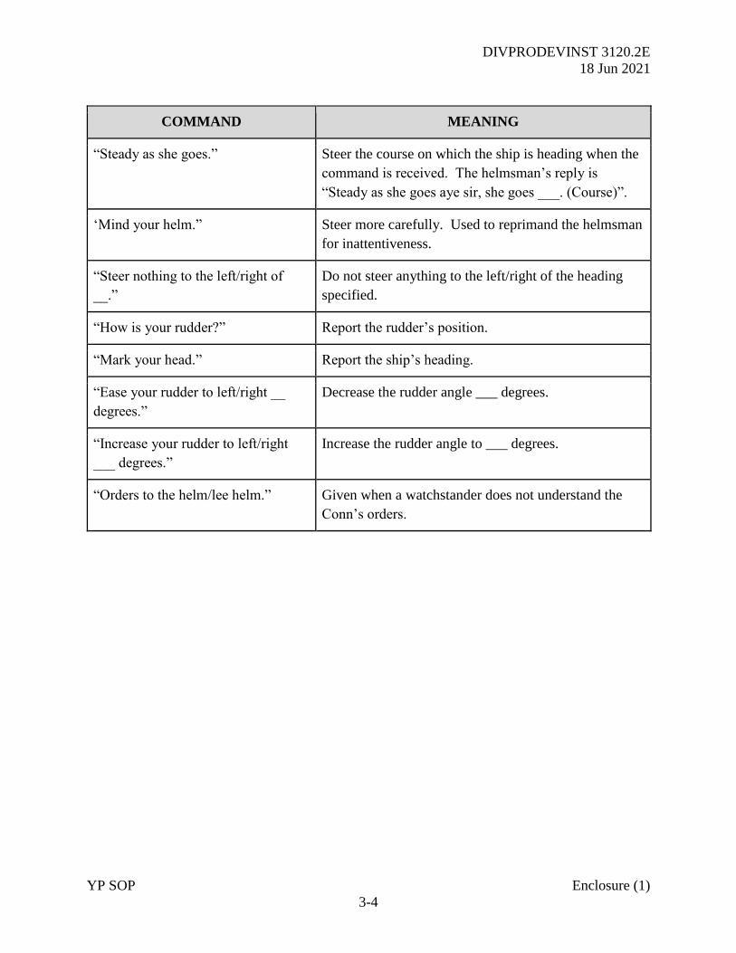
4. Standard commands to the Helmsman:
COMMAND MEANING
“Left (Right) ___ Degrees Rudder.” Put on the amount of rudder ordered.
“Left (Right) Standard Rudder.” Put on the amount of rudder required to turn the ship in
standard tactical diameter (This is 15 degrees on a YP).
“Left (Right) Full Rudder.” Put on the amount of rudder required to turn the ship in
reduced tactical diameter (25 degrees on 676 class, 30
degrees on 703 class).
“Hard Left (Right) Rudder.” Use maximum rudder. (Reserved for emergencies, 30
degrees on 676 class, 35 degrees on 703 class) Note:
does not follow the usual format as “hard” comes
before direction of the rudder.
“Steady on course ___.” Steady on course ___ using the amount of rudder
previously ordered.
“Shift your rudder.” Change from left to right rudder (or vice-versa) an
equal amount. Example: Shifting from right standard to
left standard rudder.
“Rudder amidships.” Put the rudder amidships; a rudder angle of zero
degrees.
“Come right (left) steer course ___.” Used when the ordered course change is less than 10
degrees.
“Meet her.” Use rudder as necessary to check the swing of the YP
without steadying on a specific course. Must be
immediately followed by an order to steady on a
specific course.
DIVPRODEVINST 3120.2E
18 Jun 2021
YP SOP Enclosure (1)
3-4
COMMAND MEANING
“Steady as she goes.” Steer the course on which the ship is heading when the
command is received. The helmsman’s reply is
“Steady as she goes aye sir, she goes ___. (Course)”.
‘Mind your helm.” Steer more carefully. Used to reprimand the helmsman
for inattentiveness.
“Steer nothing to the left/right of
__.”
Do not steer anything to the left/right of the heading
specified.
“How is your rudder?” Report the rudder’s position.
“Mark your head.” Report the ship’s heading.
“Ease your rudder to left/right __
degrees.”
Decrease the rudder angle ___ degrees.
“Increase your rudder to left/right
___ degrees.”
Increase the rudder angle to ___ degrees.
“Orders to the helm/lee helm.” Given when a watchstander does not understand the
Conn’s orders.
DIVPRODEVINST 3120.2E
18 Jun 2021
YP SOP Enclosure (1)
3-5
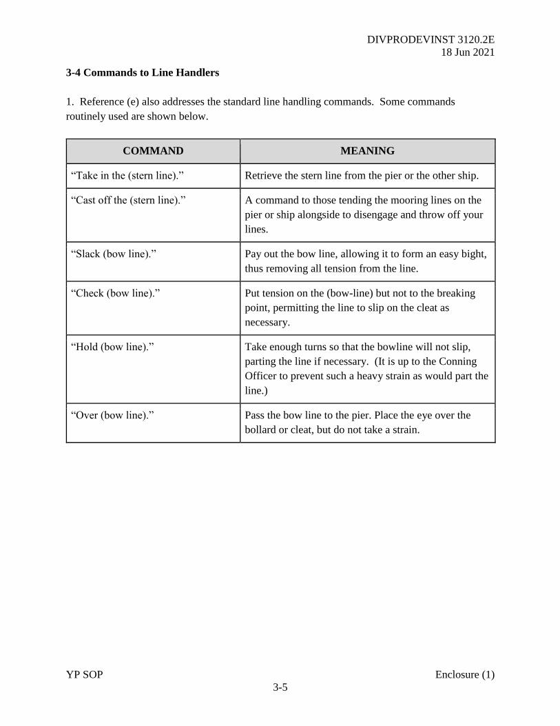
3-4 Commands to Line Handlers
1. Reference (e) also addresses the standard line handling commands. Some commands
routinely used are shown below.
COMMAND MEANING
“Take in the (stern line).” Retrieve the stern line from the pier or the other ship.
“Cast off the (stern line).” A command to those tending the mooring lines on the
pier or ship alongside to disengage and throw off your
lines.
“Slack (bow line).” Pay out the bow line, allowing it to form an easy bight,
thus removing all tension from the line.
“Check (bow line).” Put tension on the (bow-line) but not to the breaking
point, permitting the line to slip on the cleat as
necessary.
“Hold (bow line).” Take enough turns so that the bowline will not slip,
parting the line if necessary. (It is up to the Conning
Officer to prevent such a heavy strain as would part the
line.)
“Over (bow line).” Pass the bow line to the pier. Place the eye over the
bollard or cleat, but do not take a strain.
DIVPRODEVINST 3120.2E
18 Jun 2021
YP SOP Enclosure (1)
4-1
CHAPTER 4
STANDARDS OF CONDUCT
4-1 Objectives
1. USNA YPs are used to train midshipmen underway in a dynamic and realistic maritime
environment. These craft, in conjunction with SEANAV classes, allow our personnel to enhance
the key maritime skills of seamanship, navigation, and leadership.
2. The highest standards of professional behavior are required at all times. Although the
primary mission is to train midshipmen, the YPs allow junior officers to regularly be entrusted
with command at sea for an extended period underway.
3. Personnel should remain vigilant and make best use of their professional experience when
tackling any problem or situation encountered underway.
4. Every opportunity should be taken to develop student proficiency with all aspects of
navigation, engineering, and deck operations.
4-2 Standards of Professionalism
1. Military bearing, conduct, and standards of seamanship practiced aboard YPs shall at all times
reflect the pride and professionalism expected of the U.S. Navy.
2. The following general standards of smartness will be complied with by instructors,
midshipmen, and enlisted personnel when onboard:
a. All personnel will be in the uniform of the day, as detailed in the POW or OPORD.
NWUs or FRV coveralls may be worn underway.
b. All hands may wear a regulation command ball cap in lieu of a combination cover. These
caps may be either of USNA/NSAA issue.
c. During periods of inclement weather, YP Crew and Instructors are authorized to wear foul
weather jackets supplied by SEANAV.
d. Midshipmen will use issued foul weather gear during inclement weather.
e. The class Section Leader shall board the YP upon the completion of the pier side muster
and report the number of students present to the OIC and CM.
f. Morning colors will be executed by the enlisted crew when not embarked by Midshipmen
Out of Area.
DIVPRODEVINST 3120.2E
18 Jun 2021
YP SOP Enclosure (1)
4-2
g. Colors will be shifted in a smart, military manner when getting underway, anchoring, or
when mooring. The OIC/CM may raise the Ensign early if the wind conditions pose a snagging
hazard with the radar antenna.
h. In the 703 Class, the OIC / CM is to ensure the radar is turned off before hoisting or
lowering the ensign.
i. Standard commands and timely, accurate reports are to be used at all times. Standard RT
procedures are to be used when communicating over any circuit.
4-3 Operational Standards
1. The cleanliness of all compartments is to be maintained in order to stop the spread of illness
and disease. When operating in the Local Area, the enlisted crew shall manage cleaning bills
under the direction of the CM. Out of Area, the Midshipman XO shall coordinate cleaning bills.
In any case, all personnel embarked are personally responsible for highlighting and rectifying
shortfalls in cleanliness.
2. Particular focus must be placed on personal, galley and food hygiene when preparing meals.
Cleanliness standards must be impeccable, as food-borne illness is the fastest way to take down
the entire ship.
3. The CM shall ensure all sections are fully secured for sea when getting underway.
4. The craft shall render appropriate honors in accordance with the guidance detailed in Chapter
9. Personnel shall remain alert to ships and other boats that may require such protocol.
5. The crew shall properly use, maintain, and protect all equipment aboard YPs. Signal flags,
binoculars and other equipment will be stowed at the end of each class unless otherwise directed.
6. When conducting exercises, such as man-overboard drills, the crew shall use the proper visual
signals and whistle signals.
DIVPRODEVINST 3120.2E
18 Jun 2021
YP SOP Enclosure (1)
5-1
CHAPTER 5
OUT OF AREA OPERATIONS AND CERTIFICATION
5-1 Purpose. YPs routinely operate outside the Annapolis Operations Area (OPAREA) for
training and maintenance tasking. While OOA, YPs and their crews lack immediate support in
the event of an incident. Therefore, a certification process is necessary to ensure Crews and
Midshipmen have the requisite qualifications and experience to operate safely and manage the
additional challenges that arise when deployed away from USNA. It is essential that senior
personnel assess both watch team proficiency and YP material readiness before any approved
departure of the OPAREA, regardless of the planned duration of the voyage.
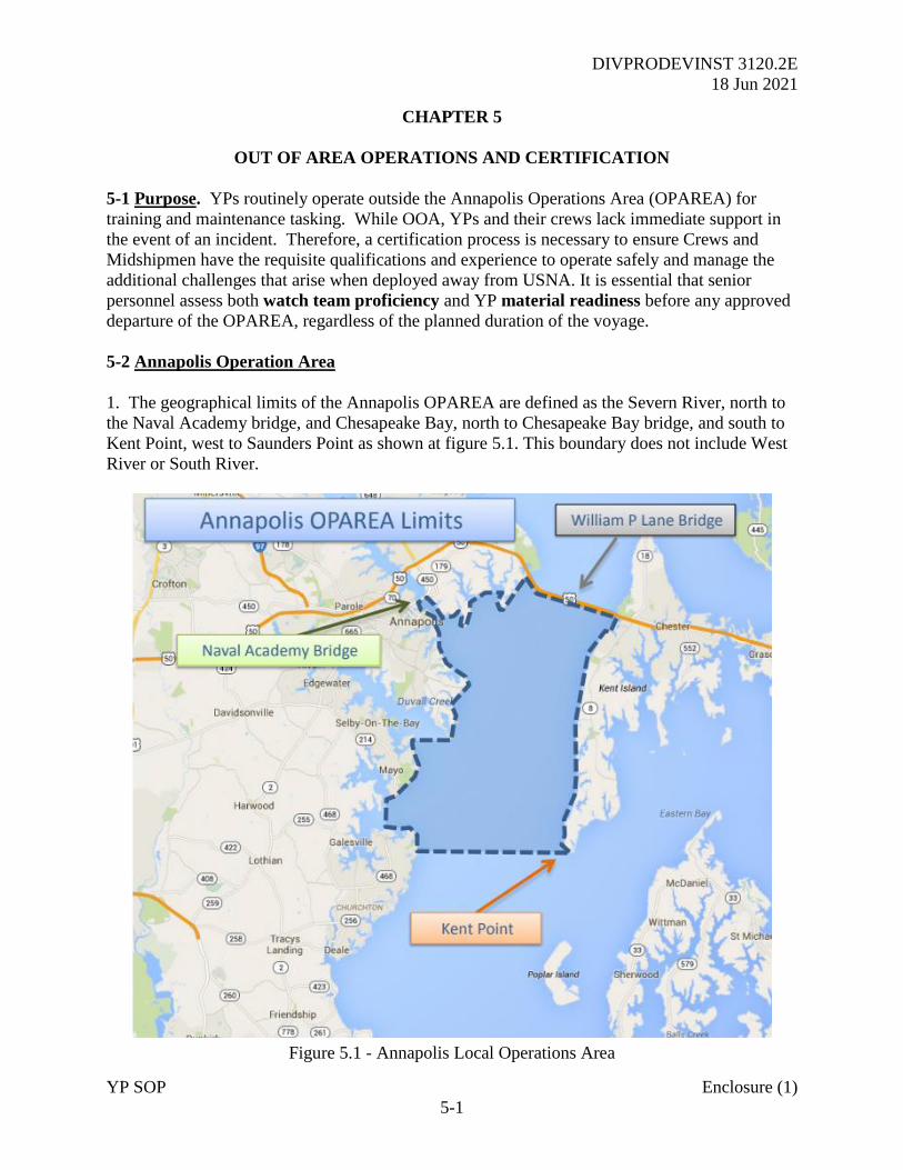
5-2 Annapolis Operation Area
1. The geographical limits of the Annapolis OPAREA are defined as the Severn River, north to
the Naval Academy bridge, and Chesapeake Bay, north to Chesapeake Bay bridge, and south to
Kent Point, west to Saunders Point as shown at figure 5.1. This boundary does not include West
River or South River.
Figure 5.1 - Annapolis Local Operations Area
DIVPRODEVINST 3120.2E
18 Jun 2021
YP SOP Enclosure (1)
5-2
5-3 Out of Area Operation Approval
1. PRODEV shall approve OPORDS for all tasking outside of the Annapolis Local OPAREA, to
include maintenance, training and research. The OPORD details mission specifics and additional
preparations, publications, equipment or training required beyond those stated in this document.
2. For missions involving maintenance or academic tasking not involving Midshipmen (Service
Life Extension Program (SLEP), Airwake, Oceanography tasking), the Waterfront Readiness
Operations Officer is responsible for drafting and submitting an OPORD through SEANAV for
PRODEV approval. Early discussion is required to ensure a nominated, OIC qualified, Officer
in Tactical Command (OTC) is able to execute the mission. For academic tasking, the OPORD
may be a standing document to cover multiple missions over a specified period of time not to
exceed one semester.
3. For SEANAV and Waterfront Readiness Staff training missions, the SEANAV Operations
Officer is responsible for drafting and submitting the OPORD for SEANAV and PRODEV
approval. SEANAV may be delegate this task to the nominated OTC for training purposes, with
the SEANAV Ops Officer retaining overall responsibility for the document.
4. For YP Squadron (YPRON) training MOs, the nominated YPRON Representative Lieutenant
within SEANAV is responsible for drafting and submitting an OPORD for SEANAV and
PRODEV approval. While he or she may delegate staff work to MIDN for training purposes,
responsibility for the correct content remains with the YPRON Representative, who should liaise
closely with the SEANAV Ops Officer and nominated OTC before submission of the document
to PRODEV.
5. For Atlantic Professional Afloat Training (LANTPAT), the nominated OTC for each
scheduled Block of training is responsible for drafting and submitting an OPORD for SEANAV
and PRODEV approval, with the nominated LANTPAT Operations Officer providing staffing
support.
5-4 Requirements for Leaving Annapolis OPAREA.
1. Goal. To ensure a YP is ready in all respects to deploy, an Out of Area (OOA) Assessment is
required to take place a minimum of 1 week in advance of tasking to ensure any material or
training shortfalls can be rectified. This assessment is designed to ensure that personnel are
properly trained and qualified and that the material state of the YP supports the mission. The
OPORD will detail specific assessment criteria, as required by tasking.
2. For tasking such as LANTPAT, OTCs, OICs, AOICs and CMs may also require additional
training and assessment to ensure they are suitably qualified and experienced to operate for
extended periods away from USNA. OICs shall consider certification when detailing watchbills
and developing a training plan prior to tasking. For LANTPAT, the DIVPRODEVINST 1531
series details this requirement.
DIVPRODEVINST 3120.2E
18 Jun 2021
YP SOP Enclosure (1)
5-3
3. YPs operating OOA will usually do so in company under the Command of a nominated OTC.
Assessing Officers (AO) will conduct the OOA embarked in each YP. SEANAV will delegate
OIC-qualified officers O4 or above to support the assessment. A senior AO will collate OOA
assessments from each deploying craft and assess the Squadron’s readiness in order to advise the
OTC and support a GO / NO-GO decision by PRODEV.
5-5 Out of Area Assessment Prerequisites
1. Goal. To ensure a YP is ready in all respects to deploy. In addition to assessing watch team
ability and the material status of the craft, the AO will evaluate the ability of the OIC, AOIC, and
CM to effectively work together supervising midshipmen while delivering the training mission
underway.
2. Watchbill. Regardless of tasking, each YP shall have a watchbill approved and signed by the
YP OIC (for midshipman) and or WFR OPS (for craft crewmembers). This bill shall detail all
required watch stations based upon operational requirements such as sea and anchor detail,
condition 3 steaming or restricted water transits. For any practical assessment, all stations will
be manned per the approved watchbill. The Assessing Officer will critique the performance of
each position and ensure the watch turnover is thorough and conducted in a timely and
professional manner.
3. Approved Charts and Navigation Brief. Each YP will have all required charting (both paper
and digital) onboard and corrected through to the latest edition of Notice to Mariners. All charts
will be reviewed by the CM, AOIC, and OIC. The overall transit plan shall be approved by
SEANAV.
4. Minimum Equipment and Training. Prior to commencing the OOA assessment, each OIC
will submit a Readiness for Sea Report (Appendix A), to the Squadron OTC stating the current
equipment readiness and level of training for the vessel. Upon completion of the OOA
Assessment, the OTC will complete Appendix C and submit the documentation to SEANAV
prior to conducting the Squadron Navigation Brief.
5-6 Out of Area Assessment
1. The OOA Assessment will form 2 parts, the progress of which are to be reported to SEANAV
if minimum requirements are not met or if there is any defect to impact safety or mission
capability. Assuming success, a summary of highlights or any shortfalls in either training or
material state are to be briefed at the Transit Brief.
2. Material State. Prior to the material assessment, OICs, AOICs and CMs should work together
to review and understand the state of the craft. At the point of inspection, the OIC should be able
to lead the Assessing Officer through the craft, highlighting any material shortfalls that have
been observed and the plan for rectification. The ensures that the OIC understands craft
capability; not just the CM. Guidance for material inspection is detailed at Appendix C.
DIVPRODEVINST 3120.2E
18 Jun 2021
YP SOP Enclosure (1)
5-4
3. Underway Assessment Execution. The OOA Assessment Checklist at Appendix C will be
used by the AO. The OIC and midshipmen CO should meet the AO on arrival and escort him or
her to the Navigation Brief. Following the brief, the AO will walk the craft to make a material
assessment of all key compartments, essential ship’s systems, survival, and damage control
equipment.
4. YPs will then conduct an underway transit to include simulated casualties and watch turnover.
Personnel on the watch should be in the positions assigned to them in the approved watchbill.
5. Any planned modifications of the OOA must be submitted and approved by SEANAV.
5-7 Post Assessment Action
1. Certification. Once the assessment is complete, the AO will debrief the OIC and CM locally.
The grading criteria are as follows: Effective, Partially Effective, and Not Effective. Any YP
assessed as “effective” is cleared OOA operations without further action. A “partially effective”
YP may be subject to a further reassessment as directed by the AO.
2. Failure to Certify. A YP assessed as “not effective” does not meet the required standard and
will not leave the local OPAREA without an additional period of training and further assessment.
3. Results. The AO is to provide a verbal report to the senior AO who will collate the results
prior to briefing SEANAV with the outcome of the serial, including key strengths and identified
shortcomings of the period underway.
5-8 After Action Reporting
1. Once the OOA operation is completed, the OTC will submit an After Action Report is to be
submitted by the OTC to PRODEV. In particular, this should focus on any incidents or issues
encountered during the mission and what steps were taken to rectify or mitigate the issue.
2. Lessons Learned. The report shall include lessons learned, which the SEANAV Ops Officer
will collate and share to improve future training and missions.

DIVPRODEVINST 3120.2E
18 Jun 2021
SECTION 2
EXECUTIVE AND ADMINISTRATION
DIVPRODEVINST 3120.2E
18 Jun 2021
YP SOP Enclosure (1)
6-1
CHAPTER 6
SAFETY
6-1 Purpose
1. Safety is fundamental to our mission as we seek to give Midshipmen the basic skills and
knowledge to operate at sea. The guidance offered below is general in nature; more detailed and
specific information can be found in relevant chapters or the following U.S. Navy publications:
a. Naval Ships Technical Manuals
b. OPNAVINST 5100.19 (series)
c. Appropriate technical and operating manuals
d. Planned Maintenance System (PMS) cards
2. Establishing and maintaining a safe training environment is the first and foremost concern of
all onboard. All personnel must be familiar with this chapter and OICs, AOICs and CMs have a
responsibility to continuously review controlling measures to ensure safe practices at all times.
6-2 Responsibilities
1. The Officer in Tactical Command (OTC). Has overall responsibility for the safe and proper
operation of the deployed YP Squadron. All OICs and CMs are to provide a comprehensive
report across all aspects of Manpower, Equipment, Training, and Sustainability. Particular
attention must be paid to damage control and survival equipment.
2. The OIC. Has overall responsibility for the safe and proper operation of the YP. Before
assuming charge, the CM is to provide a comprehensive status report of the material condition of
the craft and summary of all enlisted crewmembers embarked.
3. The CM. Shall ensure all safety precautions are adhered to and shall train their subordinates
in all areas for the safe operation of the vessel. The CM is responsible for the timely completion
of all related PMS and ensuring they have proper inventories of all safety, damage control, and
survival equipment embarked. Such items are to be in good working order.
4. Midshipmen and Crew. Safety of personnel and equipment is the responsibility of all hands.
Anyone witnessing an unsafe act must take appropriate action to rectify the problem and report
the incident to the OIC/CM as quickly as possible.
DIVPRODEVINST 3120.2E
18 Jun 2021
YP SOP Enclosure (1)
6-2
6-3 Basic Safety
1. Use of Life Jackets. Life jackets shall be worn by personnel under conditions where the
possibility exists personnel will slip, fall, be thrown, or carried into the water. Life jackets shall
be worn when performing the following evolutions:
a. Personnel working over the side of the boat, both inport and underway.
b. Personnel shall wear hard hats during special deck evolutions such as towing and
anchoring. Consideration shall also be given to the wearing of life jackets during serials such as
personnel transfers.
c. Eye protection is to be worn during all anchoring or any evolutions where there is risk of
metallic debris kicking up.
d. Personnel on the weather decks during heavy weather. The OIC/CM shall ensure the
word is passed over the 1MC to all hands the weather decks are secured due to heavy weather.
2. Working with lines and rigging. To avoid injury to personnel and damage to equipment, the
following precautions should be observed when working with lines or rigging:
a. Lines or rigging under heavy strain should be eased to prevent overstress or parting,
unless specifically ordered otherwise by the OIC or CM.
b. Handling of lines and rigging requires personnel take care to avoid getting hands, feet, or
clothing caught in bights and blocks.
c. Lines not in use should be carefully made up and stowed clear of walkways and
passageways.
d. All line handling by midshipmen should be supervised by a qualified line handler.
e. Anyone handling lines shall remove all rings, watches or other jewelry.
3. Nighttime Operations. The OTC is to limit evening tactical maneuvers to the extent that the
risk of collision is minimized.
4. Safety Precautions
a. Do not sit or lean on lifelines.
b. Thorough shipboard training of the midshipmen and crew is mandatory prior to getting
underway. This requirement can be met, for the midshipmen, in the classroom prior to getting
underway for labs and refresher classroom training prior to getting underway for operations out
of the local OPAREA. During LANTPAT, the SOE must include a Fast Cruise serial.
DIVPRODEVINST 3120.2E
18 Jun 2021
YP SOP Enclosure (1)
6-3
c. DO NOT operate any machinery with a danger tag.
d. Double hearing protection shall be worn when entering the engineering space when
main engines and/or the ships generators are in operation.
6-4 Safety Equipment
1. Emergency Escape Breathing Device (EEBD). All midshipmen shall be instructed in the
proper use and donning procedures of the EEBD. Prior to getting underway outside the local
OPAREA, a familiarization tour should be conducted to show the midshipmen where EEBDs are
located and an emergency egress drill should be conducted.
2. Kapok Lifejackets. During familiarization tours, the midshipmen shall be instructed on the
proper donning procedures of the Kapok lifejacket.
3. First Aid Procedures. All first aid should be conducted by either the duty corpsman or a
qualified individual. Every injury must be reported to the OIC/CM and he/she shall ensure the
event is properly recorded in the deck log. DO NOT attempt to administer first aid or come in
physical contact with an electric shock victim before the power is shut off, or, if the power
cannot be shut off immediately, before the victim has been removed from the live conductor.
6-5 Maritime Sanitary Discharge (MSD) System Pumping Procedures
1. Personnel engaged in sewage transfer hose operations shall not connect or disconnect hoses
used for potable water and shall wear protective rubber gloves, rubber boots, and coveralls.
2. The sewage hose connection and the hose exterior shall be washed down with hot potable
water, containing a stock detergent, and hose down with seawater or fresh water any time the
sewage hose is disconnected after transfer operations and any time a sewage spill occurs.
3. Personnel involved in the transfer shall use hand held radios or sound powered phones
whenever voice communication is impeded.
4. Strict adherence to EOSS Sewage Disposal System will be followed. The CM must verify the
system alignment prior to pumping operations.
5. The following documents will be followed when pumping Collection Holding and Transfer
(CHT) waste inport and in the event of an MSD spill while underway or inport.
a. NSTM S9086-T8-STM-010/CH-593 Section 4
b. NSTM Chapter 997
c. CP. NO.SDS
d. EOSS S.D. NO. DCHT
DIVPRODEVINST 3120.2E
18 Jun 2021
YP SOP Enclosure (1)
6-4
6. Instructions in S9086-T8-STM-010/CH-593 and NSTM CH-593 must be followed.
7. Sewage may be pumped over the side when outside 3NM of the coast or when deemed a
hazard to personnel on the vessel. When this happens, the OIC/CM will log the position at
which the pumping occurred.
6-6 Summary. The importance of safety cannot be overstated. As a general principle, if any
doubt exists during an evolution where safety is being jeopardized, then the action should be
stopped immediately. Any OPORD for an OOA deployment must include allocation of time for
safety training by qualified personnel prior to getting underway in order to reduce risk of injury.
DIVPRODEVINST 3120.2E
18 Jun 2021
YP SOP Enclosure (1)
7-1
CHAPTER 7
CRAFT’S BILLS
7-1 Craft’s Bills
1. A ship’s bill establishes assignment of personnel to duties and stations for the purpose of
executing specific evolutions or accomplishing certain functions. Those evolutions for which
assignments are made on the Watch, Quarter, and Station Bill are arbitrarily called “ship’s bills”.
Ship’s bills as contained in this chapter will be used on YPs during training cruises.
2. YP ship’s bills are constructed for basic mission training, with a crew consisting of officers,
enlisted personnel, and midshipmen with varied levels of experience. Specific assignment of
responsibilities for individuals must be completed by the OIC prior to getting underway.
3. All approved watch bills are to be posted in the pilothouse prior to departure and signed by
the OIC, AOIC, and CM.
7-2 Administrative Bills
7-2.1 Daily Routine. The standard daily UNDERWAY and INPORT routine onboard YPs is
detailed at Appendix D. Further detail will be provided in the SOE included with the OPORD.
7-2.2 Darken Ship Bill
1. The MCO and enlisted Engineer are responsible for the maintenance and accuracy of this bill.
2. Five minutes prior to sunset, the word is passed, “Prepare to darken ship”. To ensure the YP
is dark, enlisted crew are to ensure all assigned spaces are effectively darkened.
3. When darken ship is ordered, the word, “Darken ship. The smoking lamp is out on all-
weather decks”, is passed. From this time there will be no smoking, portable lights, or open
flame permitted in any area where the light will shine out of the ship. No personnel are to
proceed onto the weather deck without the permission of the OOD. Navigation lights are never
turned off during periods of darken ship.
7-2.3 Mess Cooks
1. The Midshipmen Executive Officer (MXO) will coordinate with the Midshipman
Commanding Officer (MCO) in preparing this bill.
2. The MXO will appoint, on a daily basis, a duty mess cook, and a duty mess attendant from
each watch section. Once assigned, those personnel will assist the MXO in carrying out the
duties for meal preparation, setting up for meals, and clean up when the meal is secured.
DIVPRODEVINST 3120.2E
18 Jun 2021
YP SOP Enclosure (1)
7-2
3. The mess cooking assignments will be published by the MXO (posted on the mess deck’s
bulletin board) prior to all underway evolutions. The MXO will ensure assignments do not affect
the underway watch rotation. The off-duty watch section will be responsible for preparing and
serving meals. They will then relieve the watch and the responsibility for cleanup will shift to
the two midshipmen who have just been relieved from the underway watch.
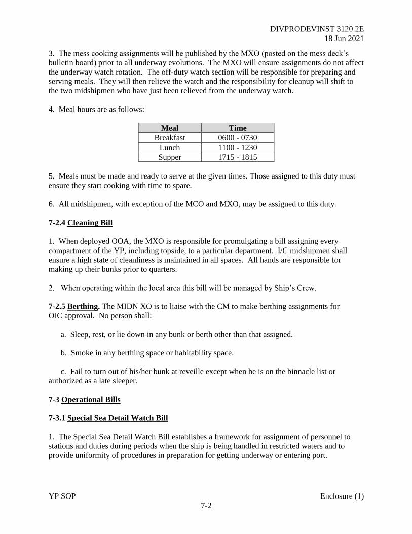
4. Meal hours are as follows:
Meal Time
Breakfast 0600 - 0730
Lunch 1100 - 1230
Supper 1715 - 1815
5. Meals must be made and ready to serve at the given times. Those assigned to this duty must
ensure they start cooking with time to spare.
6. All midshipmen, with exception of the MCO and MXO, may be assigned to this duty.
7-2.4 Cleaning Bill
1. When deployed OOA, the MXO is responsible for promulgating a bill assigning every
compartment of the YP, including topside, to a particular department. I/C midshipmen shall
ensure a high state of cleanliness is maintained in all spaces. All hands are responsible for
making up their bunks prior to quarters.
2. When operating within the local area this bill will be managed by Ship’s Crew.
7-2.5 Berthing. The MIDN XO is to liaise with the CM to make berthing assignments for
OIC approval. No person shall:
a. Sleep, rest, or lie down in any bunk or berth other than that assigned.
b. Smoke in any berthing space or habitability space.
c. Fail to turn out of his/her bunk at reveille except when he is on the binnacle list or
authorized as a late sleeper.
7-3 Operational Bills
7-3.1 Special Sea Detail Watch Bill
1. The Special Sea Detail Watch Bill establishes a framework for assignment of personnel to
stations and duties during periods when the ship is being handled in restricted waters and to
provide uniformity of procedures in preparation for getting underway or entering port.
DIVPRODEVINST 3120.2E
18 Jun 2021
YP SOP Enclosure (1)
7-3
2. The OIC/CM is responsible for the assignment of billets and execution of this watch bill and
the evolution IAW the relevant checklists.
7-3.2 Towing Bill
1. This bill establishes policies for assignment of personnel to stations and duties, designate
material which would normally be employed and promulgate the procedures to be followed
when the YP craft is either towing or being towed.
2. The OIC/CM shall be responsible for the execution of this bill. Chapter 20 details the towing
equipment to be provided on each YP by Waterfront Readiness. The OIC/CM of the towing YP
will be in charge of all rigging and the subsequent towing until completion of the serial.
3. During the course of YP operations, the possibility of a disabling propulsion casualty is ever
present. In such an instance, a towing operation would be required in order to get the disabled
craft into a Naval Station or some other repair facility for defect rectification. For this reason,
towing gear is to be carried on all YPs and the OIC/CM must be sufficiently competent in towing
procedures to direct a safe and successful towing operation.
7-3.3 Heavy Weather Bill
1. This bill details heavy weather preparations and procedures.
2. Securing a vessel properly for heavy weather is essentially a matter of foresight. The
OIC/CM must use best judgment in anticipating bad weather so proper precautions may be taken
early. In a YP, the simplest tasks may become most difficult in heavy weather.
3. All loose equipment must be secured for sea to reduce the possibility of damage or loss of the
equipment, damage to the vessel, or personnel injury. Life jackets, foul weather gear, extra lines,
padding, or other equipment needed from the lazarette or fantail storage lockers should be
broken out early and moved within the superstructure before the seas make the fantail untenable.
The galley and mess decks should be secured and stowed. The ship should be checked for
watertight integrity and topside vent covers and hatches should be secured to prevent flooding.
4. Weather decks subject to the seas should be kept clear of all personnel except those attending
urgent duties. Anyone wishing to proceed onto the weather deck must first get permission from
the OOD and is not to venture alone or without a Kapok life jacket. A lifeline tended from
within the superstructure should also be considered.
7-3.4 Inport Refueling Bill
1. YPs will ordinarily be refueled to 80% to support training tasks throughout the academic year.
Any craft scheduled to depart the USNA OPAREA for summer training will be refueled to 85%.
2. The Refueling Officer shall be responsible to the OTC for the execution of this bill. All
hands shall have the authority to stop fueling operations for any reason, particularly safety, at
DIVPRODEVINST 3120.2E
18 Jun 2021
YP SOP Enclosure (1)
7-4
any time. Before starting the actual evolution of receiving diesel oil from a barge, truck, another
YP, or pier, the following will be completed before permission to commence pumping is
obtained from the OTC:
a. The smoking lamp is out and flag “Bravo” is flying.
b. Two PKP bottles are to be ready at the refueling station.
c. Scuppers and topside drains will be plugged with clean rags or water-filled plastic bags.
Any spill of oil cannot be allowed to drain overboard. The spill kit is to be available at the
refueling station.
d. An oil boom is to be rigged as required.
e. Valve alignment will be verified by the enlisted engineer, CM and Refueling Officer.
4. Stations to be manned:
a. Engine room (1JV).
b. Fueling Station/Overflow (1JV).
c. Pumping Station.
d. Intermediate Station.
e. The Intermediate Station will ensure proper communications are maintained between the
pumping and fueling station.
f. A maximum rate of 100 gallons per minute will be maintained while refueling. 10, five
and one-minute standby calls will be signaled by the engine room watch monitoring the fuel tank
gauge glass. At the five-minute standby, the pumping rate will be reduced to four gallons per
minute.
7-3.5 Equipment Tag Out Bill
1. Reference (k) details standard indication of equipment status by using red danger tags and
yellow caution tags and the procedure to be followed marking these indications. This instruction
is included as a permanent part of the Equipment Tag-Out Log onboard each YP. Reference (k)
provides a list of personnel assigned to specific billets and appointed as “Authorizing Officers”
for tag-outs onboard designated YPs and other small boats.
2. Anyone with questions concerning tagged-out equipment or inoperative equipment should
consult the CM or enlisted Engineer. No midshipman will clear any existing tags. Tags will
never be affixed or removed without approval of the nominated Tag Out Authorizing Officer.
DIVPRODEVINST 3120.2E
18 Jun 2021
YP SOP Enclosure (1)
8-1
CHAPTER 8
LOGS AND RECORDS
8-1 Logs and Records
1. It is essential reliable records of the actions taken aboard a ship in times of combat, danger, or
precise navigation be maintained for legal reasons. Of less obvious importance is the recording
of everyday routines and employment of the ship which may someday be of historical
significance.
2. Log requirements:
a. All U.S. Navy ships shall maintain a ship’s Deck Log (DL) at all times. Although not
commissioned vessels, watchstanders onboard YPs will adhere to the requirements of reference
(b) with the following exceptions:
(1) If the CM is the sole watchstander on the bridge then course, speed, engine, and
rudder orders will not be logged. Where available, the Voyage Data Recorder (VDR) should be
enabled.
(2) If YP tasking is within the limits of the Annapolis OPAREA for the purposes of an
academic class then course, speed, engine, and rudder orders will not be logged.
b. The Bearing Book (BB) will be maintained by the Navigator whenever YPs operate
beyond the limits of the Annapolis OPAREA. While in the OPAREA and conducting a lab or
other period of training, the BB shall be maintained so far as practicable.
c. The Engineer’s Log shall be maintained by the enlisted Engineer and assigned
midshipmen assistants whenever engineering equipment is being operated. The Bell Book is a
chronological record of orders pertaining to the speed of the propulsion engines and will be
maintained by the EOS watch when practicable to do so.
d. The Position Log will be maintained by the Plotter on the bridge whenever YPs operate
beyond the limits of the OPAREA.
3. 703 class specifics. When operating the craft’s VDR and navigating using digital procedures
with a fully serviceable ECDIS, only the Deck Log is required to be maintained.
8-2 YP Deck Logs
1. The YP’s deck log (DL) is the official daily record of the craft, by each watch. The DL
describes every circumstance and occurrence of importance or interest that concerns the crew,
the operation or safety of the ship. The DL shall be a chronological record of those events
occurring during the watch permitting an accurate reconstruction of events to be made.
DIVPRODEVINST 3120.2E
18 Jun 2021
YP SOP Enclosure (1)
8-2
2. When kept, the DL must maintain a record of all the events of the day, particularly:
a. Every injury, accident, or casualty, however slight.
b. All accidents resulting in a loss or damage of any kind.
c. Any important actions taken. Enter a full reconstruction of the event, detailing every
occurrence and remarkable incident.
d. All peculiar or extraordinary appearances of the sea, weather, or atmosphere following
sudden changes of wind, heavy squalls of wind or sudden gales. Also, tidal conditions, sighting
of discolored water, extraordinary luminescence or other unexpected phenomenon.
e. The name of the OIC / Class Instructor and Section and any additional passengers, such as
civilians or additional Crew / personnel under instruction.
f. Any soundings, the record of which is important, with character of the bottom. Report any
significant depth anomaly to the OIC and OTC immediately.
g. After anchoring, record bearings and ranges to fix the exact position of the ship.
h. When at anchor in heavy weather, the strain upon the anchor chain or cable, and other
unusual conditions.
i. A summary of orders under which the vessel moves, quoting the authority for those orders.
In general, this entry should show the character of the exercise in which the ship is engaged and
the reasons for her movements.
j. The time of reporting to, or detachment from, any tactical unit.
k. The time when any particular evolution, exercise, or other service was performed,
preparing to enter port or to anchor, anchorage, getting underway, securing anchors, preparing
the ship for heavy weather, etc.
l. All course (degrees true) and speed (knots) changes.
m. All unexplained or unauthorized absences with indication of time, occurrence and first
knowledge of absence. Surrounding circumstances and time of later whereabouts or fate.
n. Any arrival or departure of the OTC/OIC/AOIC/CM from the bridge while underway.
o. Any time a craft departs or enters OPAREA.
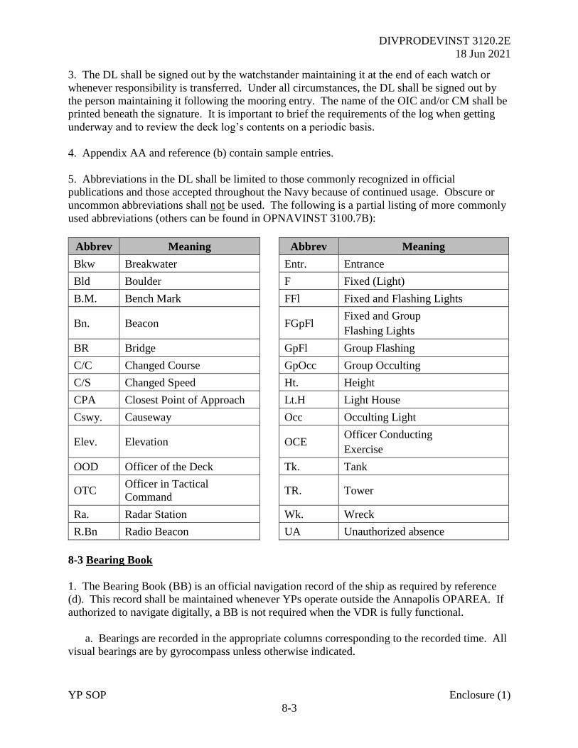
DIVPRODEVINST 3120.2E
18 Jun 2021
YP SOP Enclosure (1)
8-3
3. The DL shall be signed out by the watchstander maintaining it at the end of each watch or
whenever responsibility is transferred. Under all circumstances, the DL shall be signed out by
the person maintaining it following the mooring entry. The name of the OIC and/or CM shall be
printed beneath the signature. It is important to brief the requirements of the log when getting
underway and to review the deck log’s contents on a periodic basis.
4. Appendix AA and reference (b) contain sample entries.
5. Abbreviations in the DL shall be limited to those commonly recognized in official
publications and those accepted throughout the Navy because of continued usage. Obscure or
uncommon abbreviations shall not be used. The following is a partial listing of more commonly
used abbreviations (others can be found in OPNAVINST 3100.7B):
Abbrev Meaning Abbrev Meaning
Bkw Breakwater Entr. Entrance
Bld Boulder F Fixed (Light)
B.M. Bench Mark FFl Fixed and Flashing Lights
Bn. Beacon
FGpFl Fixed and Group
Flashing Lights
BR Bridge GpFl Group Flashing
C/C Changed Course GpOcc Group Occulting
C/S Changed Speed Ht. Height
CPA Closest Point of Approach Lt.H Light House
Cswy. Causeway Occ Occulting Light
Elev. Elevation
OCE Officer Conducting
Exercise
OOD Officer of the Deck Tk. Tank
OTC Officer in Tactical
Command
TR. Tower
Ra. Radar Station Wk. Wreck
R.Bn Radio Beacon UA Unauthorized absence
8-3 Bearing Book
1. The Bearing Book (BB) is an official navigation record of the ship as required by reference
(d). This record shall be maintained whenever YPs operate outside the Annapolis OPAREA. If
authorized to navigate digitally, a BB is not required when the VDR is fully functional.
a. Bearings are recorded in the appropriate columns corresponding to the recorded time. All
visual bearings are by gyrocompass unless otherwise indicated.
DIVPRODEVINST 3120.2E
18 Jun 2021
YP SOP Enclosure (1)
8-4
b. All soundings are recorded as depth under the keel (in feet) by fathometer unless
otherwise indicated.
c. If magnetic bearings are used, annotations should indicate so and include the compass
error (deviation and variation) of the magnetic compass platform, for the particular heading at
the time of the observation.
d. The OIC, AOIC, or CM shall sign their name following the last entry of the watch to
verify the accuracy of the recorded navigation information.
8-4 Engineer’s Log. The Engineering Log is a chronological narrative similar to the DL but
instead describes the circumstances and occurrences concerning operation and safety of the
engineering plant and auxiliary systems. The log shall indicate the times and specific changes to
the plant status. Equipment status and problems relating to the mechanical condition of the
different components are of particular interest. This is the YPs primary engineering record book.
8-5 Position Log. The Position Log shall be a complete record of the vessel’s position while
operating outside of the Annapolis OPAREA. After each fix (visual, radar, or GNSS) the
vessel’s position shall be logged in latitude/longitude format (WGS84). The registered
fathometer reading at the time of the fix shall also be recorded in the Position Log. If authorized
to navigate digitally this log is not required provided the VDR is fully functional.
8-6 Corrections to Deck and Engineering Logs
1. An entry into either official log shall not be erased. When a mistake is made, a single line
shall be drawn through the original entry so the text remains legible. The corrected entry shall
then be made in the log. Corrections shall be initiated on the left of the time entry on the same
line as the correction or error by the person who is required to sign the log, OIC, AOIC, or CM.
2. No changes shall be made after the log is signed.
8-7 Retention Requirements. Copies of the Deck Log and Engineering Log shall be retained
for one year by the Senior CM and TOP Snipe respectively. The SEANAV Operations Officer
shall retain VDR files for any OOA deployment indefinitely.
DIVPRODEVINST 3120.2E
18 Jun 2021
YP SOP Enclosure (1)
9-1
CHAPTER 9
HONORS AND CEREMONIES
9-1 General. The honors and ceremonies prescribed in this chapter are selected from several
sources. Further information may be found in the references.
9-2 Display of the National Ensign
9-2.1 Underway. The national ensign shall be displayed from the gaff of a YP at all times while
underway unless otherwise ordered by the OTC, SEANAV or WFR Director.
9-2.2 Not Underway. When not underway the national Ensign and the Jack shall be displayed
from 0800 until sunset from the flagstaff and the jackstaff respectively.
9-2.3 Shifting Colors
1. When preparing to anchor or moor, personnel shall be stationed at the flagstaff, jackstaff, and
signal deck as necessary to effect the proper change in the display of the national Ensign. As the
first mooring line is secured or the anchor is let go, the OOD/OIC/CM shall announce shift
colors over the 1MC. At this signal, the national ensign shall be lowered smartly from the gaff
as the national ensign and Jack are hoisted smartly on the flagstaff and jackstaff respectively.
2. When getting underway the same procedure shall be used to shift the display of the national
Ensign to the gaff. Other underway flag displays such as call signs or guide flags shall be
hoisted immediately after the national Ensign. The national Ensign takes priority over any other
flag.
9-2.4 Dipping
1. When any private ship, either under the United States registry or under the registry of a nation
formally recognized by the government of the United States, salutes a ship of the U.S. Navy by
dipping her ensign, it is answered “dip for dip”. The correct procedure is that when the other
ship has dipped her colors, the YP shall haul its national ensign approximately one-half way
down; pause for a brief moment and then close up smartly.
2. Private ships render dips at various hours and sometimes at considerable distances. The OOD
must therefore be alert for these occasions. If the national Ensign is not already displayed, it is
hoisted especially for answering the dip; the dip is returned, and, after a suitable interval, the
ensign is hauled down.
3. No U.S. Navy ship shall ever initiate a dip of the national Ensign. The Ensign is only
dipped in return for such a compliment by another ship.
9-2.5 Half-Masting. When half-masting the national Ensign, it is first hoisted to the peak and
then lowered slowly to the half–mast position. Before lowering from half-mast the Ensign is
DIVPRODEVINST 3120.2E
18 Jun 2021
YP SOP Enclosure (1)
9-2
first hoisted to the full peak position and then lowered. When the national Ensign is half-masted,
the union jack is likewise half-masted and in the same manner as prescribed above. When
underway, the flag is never half masted.
9-3 Honors to the National Ensign
9-3.1 Salutes on Reporting Aboard and Departing
1. Each person in the naval service, upon coming on board a ship of the U.S. Navy, shall salute
the national ensign. Permission to board or depart shall only be sought on occasions OOA.
a. Procedure for boarding a YP follows:
(1) Stop on reaching the quarterdeck area of the YP, face the national Ensign, and render
the salute.
(2) Face and salute the OOD.
(3) Say, “Request permission to come aboard, Sir/Ma’am”.
b. Upon departing, the YP the procedure is reversed:
(1) Salute the OOD.
(2) Say, “Request permission to go ashore, Sir/Ma’am”.
(3) Salute the national ensign.
9-3.2 Morning and Evening Colors
1. The ceremonial hoisting of the national Ensign in port at 0800 is known as “morning colors”
and lowering at sunset as “evening colors”. Such ceremonies shall be carried out on the
outboard YP when deployed OOA or when moored at the USNA seawall.
a. All ships follow the motions of the Pennant 1 deployed, in carrying out morning and
evening colors.
b. At 0800 or sunset, “attention” is sounded by one drawn-out blast on a hand whistle. All
hands on deck will face the national ensign and salute. If in ranks, only the man-in-charge shall
render the salute. At the sounding of 2 whistles, ready too.
c. At morning colors, the ensign shall be raised starting at “attention” and hoisted smartly.
At evening colors, the ensign shall be lowered ceremoniously.
d. At the completion of the raising/lowering of the ensign, “carry-on” is sounded by three
short blasts on a hand whistle.
DIVPRODEVINST 3120.2E
18 Jun 2021
YP SOP Enclosure (1)
9-3
e. The energizing of anchor and deck lights is usually considered a part of the evening colors
ceremony and should be accomplished at the first note of “attention”.
9-4 Quarterdeck Honors. When in port, the primary watch station is shifted from the bridge to
the quarterdeck. The quarterdeck is the ceremonial entrance and exit point of the ship, manned
24 hours a day by the inport Officer of the Deck. The inport OOD is responsible for the safety
and security of the ship and it is their duty to greet and verify every person who is boarding or
leaving the ship.
9-5 Passing Honors
1. Passing honors are those actions, other than gun salutes, which are rendered on occasions
when Navy or Coast Guard ships or embarked officials or officers pass, or are passed close
aboard.
2. United States ships, allied and foreign Warships of nations diplomatically recognized by the
U.S. Government also engage in passing honors. The term “close aboard” is defined as a
distance of six hundred (600) yards for ships and four hundred (400) yards for boats in
accordance with NTP 13B. Passing honors consist of sounding “attention” and rendering the
hand salute by all persons in view on deck (not in ranks).
3. Notably, while in the Annapolis OPAREA, YPs will not render honors to each other.
However, when the Superintendent’s Barge (C/S VICTORY) is underway and flying a blue flag
with three white stars, passing honors will be rendered in accordance with the procedure detailed
below. If VICTORY is underway not flying the aforementioned flag, the Admiral is not
embarked and honors need not be rendered.
9-5.1 Passing Honors between Ships
1. Passing honors between ships will be exchanged only when both ships are underway. In
situations where the ships are proceeding in opposite directions, passing honors are conducted
when the bow of the junior ship passes the bow of the senior ship. Due to the size of the YPs,
the sequence will probably need to be initiated sooner in order to complete the evolution when
both are beam to beam. In an overtaking situation, honors are initiated when the bow of the
overtaking ship passes the stern of the overtaken ship. Procedures for rendering passing honors
are as follows:
a. Sound “Attention” (to port or starboard as appropriate) on a whistle over the 1MC. (two
or one short, respectively).
b. Sound “Hand salute” on a whistle (1 short blast) over the 1MC.
c. When the senior returns the salute and after the senior cuts the salute, sound “Ready, to”
(two short blasts).
DIVPRODEVINST 3120.2E
18 Jun 2021
YP SOP Enclosure (1)
9-4
d. Sound “Carry on” on the whistle, after the senior has issued “Carry on” (3 short blasts).
9-5.2 Passing Honors to Officials and Officers Embarked in Boats
1. When a boat in which a senior officer is embarked passes a YP close aboard or a YP passes a
senior reviewing party, passing honors shall be rendered and all exposed personnel will respond.
This procedure is valid whether or not your YP is underway. The correct procedure is as
follows:
a. Sound “Attention” (to port or starboard as appropriate) on a whistle over the 1MC (two or
one short, respectively).
b. Sound “Hand salute” on a whistle (1 short blast) over the 1MC.
c. When the senior returns the salute and after the senior cuts the salute, sound “Ready, to”
(two short blasts).
d. Sound “Carry on” on the whistle, after the senior has issued “Carry on” (3 short blasts).
9-5.3 Dispensing with Passing Honors
1. Passing honors will not be rendered after sunset or before 0800.
2. Passing honors will not routinely be exchanged between YPs unless they are a specified part
of a drill plan. However, the OOD shall be alert to render honors to ships or boats that are not
engaged in drills, especially the Superintendent’s barge or the gigs and barges of other senior
officers.
3. The OTC may direct the passing of honors be dispensed with in whole or part.
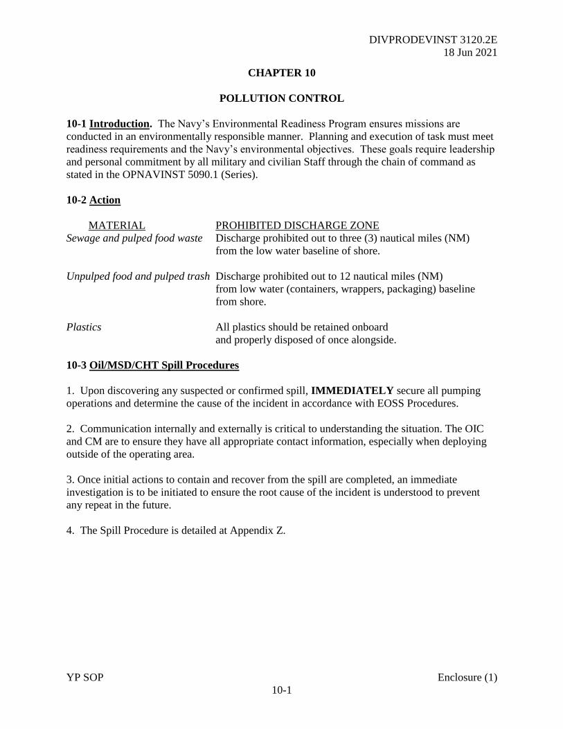
DIVPRODEVINST 3120.2E
18 Jun 2021
YP SOP Enclosure (1)
10-1
CHAPTER 10
POLLUTION CONTROL
10-1 Introduction. The Navy’s Environmental Readiness Program ensures missions are
conducted in an environmentally responsible manner. Planning and execution of task must meet
readiness requirements and the Navy’s environmental objectives. These goals require leadership
and personal commitment by all military and civilian Staff through the chain of command as
stated in the OPNAVINST 5090.1 (Series).
10-2 Action
MATERIAL PROHIBITED DISCHARGE ZONE
Sewage and pulped food waste Discharge prohibited out to three (3) nautical miles (NM)
from the low water baseline of shore.
Unpulped food and pulped trash Discharge prohibited out to 12 nautical miles (NM)
from low water (containers, wrappers, packaging) baseline
from shore.
Plastics All plastics should be retained onboard
and properly disposed of once alongside.
10-3 Oil/MSD/CHT Spill Procedures
1. Upon discovering any suspected or confirmed spill, IMMEDIATELY secure all pumping
operations and determine the cause of the incident in accordance with EOSS Procedures.
2. Communication internally and externally is critical to understanding the situation. The OIC
and CM are to ensure they have all appropriate contact information, especially when deploying
outside of the operating area.
3. Once initial actions to contain and recover from the spill are completed, an immediate
investigation is to be initiated to ensure the root cause of the incident is understood to prevent
any repeat in the future.
4. The Spill Procedure is detailed at Appendix Z.
DIVPRODEVINST 3120.2E
18 Jun 2021
YP SOP Enclosure (1)
11-1
CHAPTER 11
FORCE PROTECTION
11-1 Introduction
1. Force Protection is designed to protect personnel, facilities, and equipment under all
situations and in any location. The YPs both at USNA and when deployed are a part of the
Navy-wide plan.
2. There are many differences between a front line Destroyer and an unarmed training craft but
many of the same concepts still apply and when used correctly, will assist in protection from
terrorist attack. The measures outlined below do not account for all situations and the OTC
should, prior to arrival, consult with NCIS with respect to these plans and any local threats.
3. The five threat levels from lowest to highest are, low, guarded, elevated, high, and severe.
a. Low. Low risk of terrorist attacks.
b. Guarded. General risk of terrorist attacks.
c. Elevated. Significant risk of terrorist attacks.
d. High. High risk of terrorist attacks.
e. Severe. Severe risk of terror attacks.
11-2 Force Protection Conditions (FPCON)
1. The FPCONs outlined below describe the progressive level of countermeasures in response to
a terrorist threat to U.S. military facilities and personnel under reference (l). The terminology
and definitions are recommended security measures designed to ease inter-service coordination
and support of U.S. military antiterrorism activities. Each unit or installation must adapt these
measures for their site-specific circumstances accounting for, as a minimum, Geographic
Commander/Service requirements, local laws, and Status of Forces Agreements.
2. The FPCON system is the principal means through which a commander applies an
operational decision on how to guard against a threat. It is designed for accessibility and easy
dissemination of appropriate information. The elevation or reduction of a force protection
condition remains the exclusive responsibility of the commanders specified in the order.
3. There are five (5) different FPCONs.
a. Normal. When a general global threat of possible terrorist activity exists and warrants a
routine security posture.
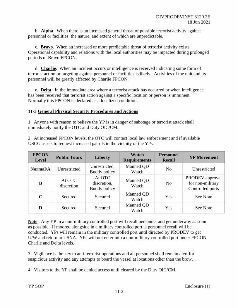
DIVPRODEVINST 3120.2E
18 Jun 2021
YP SOP Enclosure (1)
11-2
b. Alpha. When there is an increased general threat of possible terrorist activity against
personnel or facilities, the nature, and extent of which are unpredictable.
c. Bravo. When an increased or more predictable threat of terrorist activity exists.
Operational capability and relations with the local authorities may be impacted during prolonged
periods of Bravo FPCON.
d. Charlie. When an incident occurs or intelligence is received indicating some form of
terrorist action or targeting against personnel or facilities is likely. Activities of the unit and its
personnel will be greatly affected by Charlie FPCON.
e. Delta. In the immediate area where a terrorist attack has occurred or when intelligence
has been received that terrorist action against a specific location or person is imminent.
Normally this FPCON is declared as a localized condition.
11-3 General Physical Security Procedures and Actions
1. Anyone with reason to believe the YP is in danger of sabotage or terrorist attack shall
immediately notify the OTC and Duty OIC/CM.
2. At increased FPCON levels, the OTC will contact local law enforcement and if available
USCG assets to request increased patrols in the vicinity of the YPs.
FPCON
Level Public Tours Liberty
Watch
Requirements
Personnel
Recall YP Movement
Normal/A Unrestricted Unrestricted,
Buddy policy
Manned QD
Watch No Unrestricted
B At OTC
discretion
At OTC
discretion,
Buddy policy
Manned QD
Watch No
PRODEV approval
for non-military
Controlled ports
C Secured Secured Manned QD
Watch Yes See Note
D Secured Secured Manned QD
Watch Yes See Note
Note: Any YP in a non-military controlled port will recall personnel and get underway as soon
as possible. If moored alongside in a military controlled port, a personnel recall will be
conducted. YPs will remain in the military controlled port until directed by PRODEV to get
U/W and return to USNA. YPs will not enter into a non-military controlled port under FPCON
Charlie and Delta levels.
3. Vigilance is the key to anti-terrorist operations and all personnel shall remain alert for
suspicious activity and any attempts to board the vessel at locations other than the brow.
4. Visitors to the YP shall be denied access until cleared by the Duty OIC/CM.
DIVPRODEVINST 3120.2E
18 Jun 2021
YP SOP Enclosure (1)
11-3
5. High levels of activity, both onboard and on the pier side, must not be allowed to degrade
security. Those personnel standing quarterdeck watches shall not take part in other activities
allowing them to remain alert to any immediate threat.
6. Within the Duty Watch an allocated standing Quarterdeck Watch is to be nominated. They
are to check identification of all Squadron personnel when departing or arriving, monitor the YPs
and surrounding area for suspicious activity, raising the alarm in event of an emergency.
11-4 Alongside Security (Non-USNA)
1. The OTC is to obtain, prior to departure from USNA, the updated threat assessment from
NCIS. This assessment is to be briefed to both midshipmen and the crew and is to include
security precautions and recall procedures.
2. Security should be arranged ahead of time prior to arrival at any port. Local authorities will
provide protection for all YPs.
3. The OTC is to ensure duty personnel have a direct line of communication to the security
authorities ashore. Prior to arrival, in a non-Navy port, the OTC will contact local authorities to
inform them of their arrival and get up to date crime information.
4. Recall procedures are vitally important. The safest course of action to an increased terrorist
threat is likely to include getting underway. The midshipman CDO is to retain an updated recall
roster at all times. The crew and midshipmen must be able to return to the ship and get
underway within four hours. All midshipmen must use the “buddy system” when ashore.
11-5 Improvised Explosive Device (IED) Threat
1. On receipt of a bomb threat, the person receiving the threat is to immediately inform the
OTC, OIC, and the CM. Their immediate reaction is to clear the craft of all personnel, muster in
a designated area ashore, and clear of any hazards while informing the local authorities as
quickly as possible.
2. All crewmembers will conduct a quick cursory search of their spaces for suspicious items
prior to disembarking.
3. Turn off all radios and office equipment.
4. If feasible, portals and hatches should be left open to help dissipate the shockwave from any
explosion.
5. Cabinets and drawers will be left unlocked.
6. Re-entry should not be made until authorized by the local authorities.

DIVPRODEVINST 3120.2E
18 Jun 2021
SECTION 3
NAVIGATION
DIVPRODEVINST 3120.2E
18 Jun 2021
YP SOP Enclosure (1)
12-1
CHAPTER 12
YP NAVIGATION STANDARDS
12-1 Background
1. YPs are highly effective training and education platforms for Midshipmen, Officers, Junior
Enlisted and Civilian Staff. However, to remain safe and effective, proper navigation principles
must be taught and applied at all times. In particular, teams are to maintain situational awareness
in relation to safe water available. If in any doubt about the YP’s position immediately slow
down or stop. If a situation does not look right, it probably is not!
2. Conducting navigation training in a YP is very different and in many ways more challenging
than navigating a Navy warship. Significant differences include:
a. The inexperience of the unqualified midshipman watch team.
b. The absence of a secondary plot to back up to the navigation plot on the bridge.
c. The need to conduct realistic training while ensuring YP safety when underway.
3. These risks can only be mitigated by the vigilance of the OIC/AOIC/CM team in maintaining
situational awareness at all times.
12-2 Responsibility. Individual responsibilities are detailed at Chapter 2. However, the OIC is
ultimately responsible for the safety of navigation. They must work with the AOIC and CM to
ensure that correct navigational procedures are in place and being adhered to. This includes the
application of proper navigation planning prior to getting underway.
12-3 USN Policy.
1. US Navy Fleet policy documents such as NAVDORM should be adhered to when able.
However, YPs are non-commissioned and the training environment itself may make departure
from such policy necessary on occasion. However, where NAVDORM remains the primary
policy, the SOP details requirements for YP operations.
2. OICs and CMs are encouraged to continually review this SOP. Knowledge often becomes
tribal, passed down between personnel and is not formalized. This should be avoided wherever
possible by updating the associated documentation.
12-4 Training.
1. Maintaining proficiency in basic navigation skills is equally critical to safe navigation. A
thorough understanding of the operation, capabilities and limitations of all installed equipment is
essential.
DIVPRODEVINST 3120.2E
18 Jun 2021
YP SOP Enclosure (1)
12-2
2. Because YPs are not certified for digital navigation, all OICs, AOICs and CMs must be fully
conversant with the correct operation of VMS / ECDIS whilst underway. However, in the event
of equipment failure, they must also be entirely familiar with reverting to full paper navigation,
including the placement of visual, composite and electronic Lines of Position as well as the 6
rules of Dead Reckoning.
3. SEANAV and WFR are to provide a training and assessment program to educate, qualify,
evaluate and periodically re-qualify assigned personnel. All OICs/AOICs/CMs will gain
qualification and remain proficient as detailed in reference (b).
4. Prior to Out of Area Move Order, a training program is to be developed and approved by the
OTC to train and then assess watch standers before leaving the area. This is a training
environment and so OICs and CMs should be a part of and support development of the team.
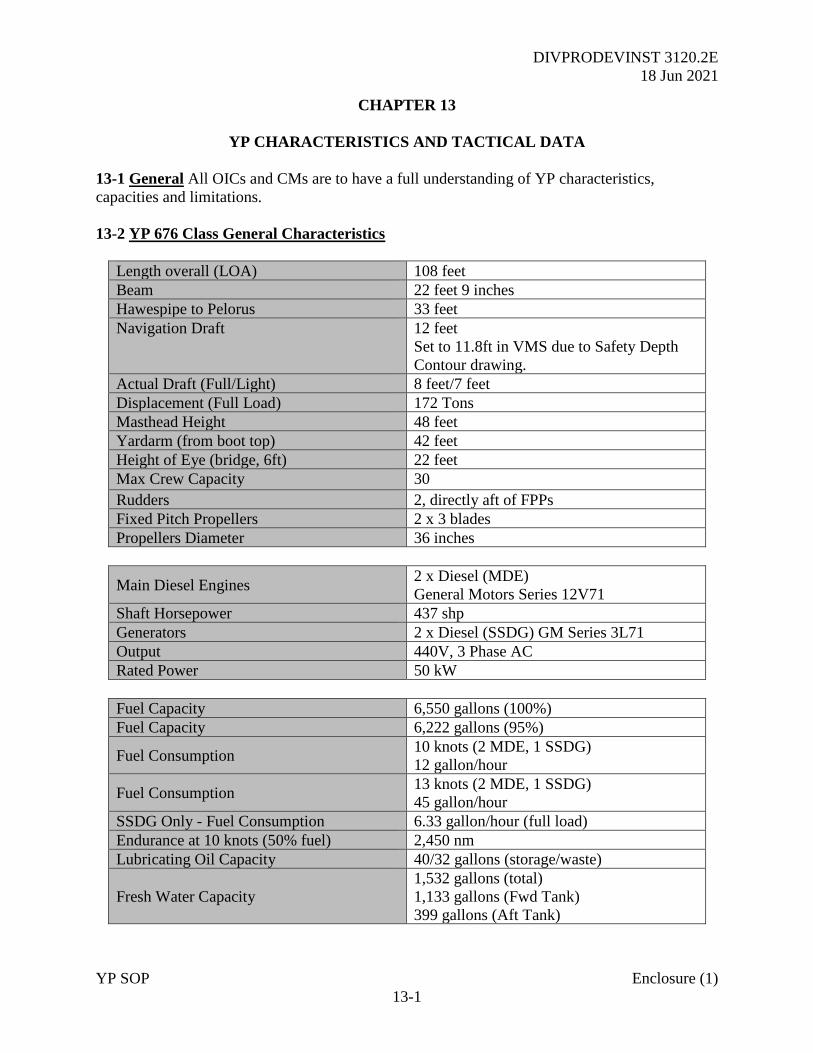
DIVPRODEVINST 3120.2E
18 Jun 2021
YP SOP Enclosure (1)
13-1
CHAPTER 13
YP CHARACTERISTICS AND TACTICAL DATA
13-1 General All OICs and CMs are to have a full understanding of YP characteristics,
capacities and limitations.
13-2 YP 676 Class General Characteristics
Length overall (LOA) 108 feet
Beam 22 feet 9 inches
Hawespipe to Pelorus 33 feet
Navigation Draft 12 feet
Set to 11.8ft in VMS due to Safety Depth
Contour drawing.
Actual Draft (Full/Light) 8 feet/7 feet
Displacement (Full Load) 172 Tons
Masthead Height 48 feet
Yardarm (from boot top) 42 feet
Height of Eye (bridge, 6ft) 22 feet
Max Crew Capacity 30
Rudders 2, directly aft of FPPs
Fixed Pitch Propellers 2 x 3 blades
Propellers Diameter 36 inches
Main Diesel Engines 2 x Diesel (MDE)
General Motors Series 12V71
Shaft Horsepower 437 shp
Generators 2 x Diesel (SSDG) GM Series 3L71
Output 440V, 3 Phase AC
Rated Power 50 kW
Fuel Capacity 6,550 gallons (100%)
Fuel Capacity 6,222 gallons (95%)
Fuel Consumption 10 knots (2 MDE, 1 SSDG)
12 gallon/hour
Fuel Consumption 13 knots (2 MDE, 1 SSDG)
45 gallon/hour
SSDG Only - Fuel Consumption 6.33 gallon/hour (full load)
Endurance at 10 knots (50% fuel) 2,450 nm
Lubricating Oil Capacity 40/32 gallons (storage/waste)
Fresh Water Capacity
1,532 gallons (total)
1,133 gallons (Fwd Tank)
399 gallons (Aft Tank)
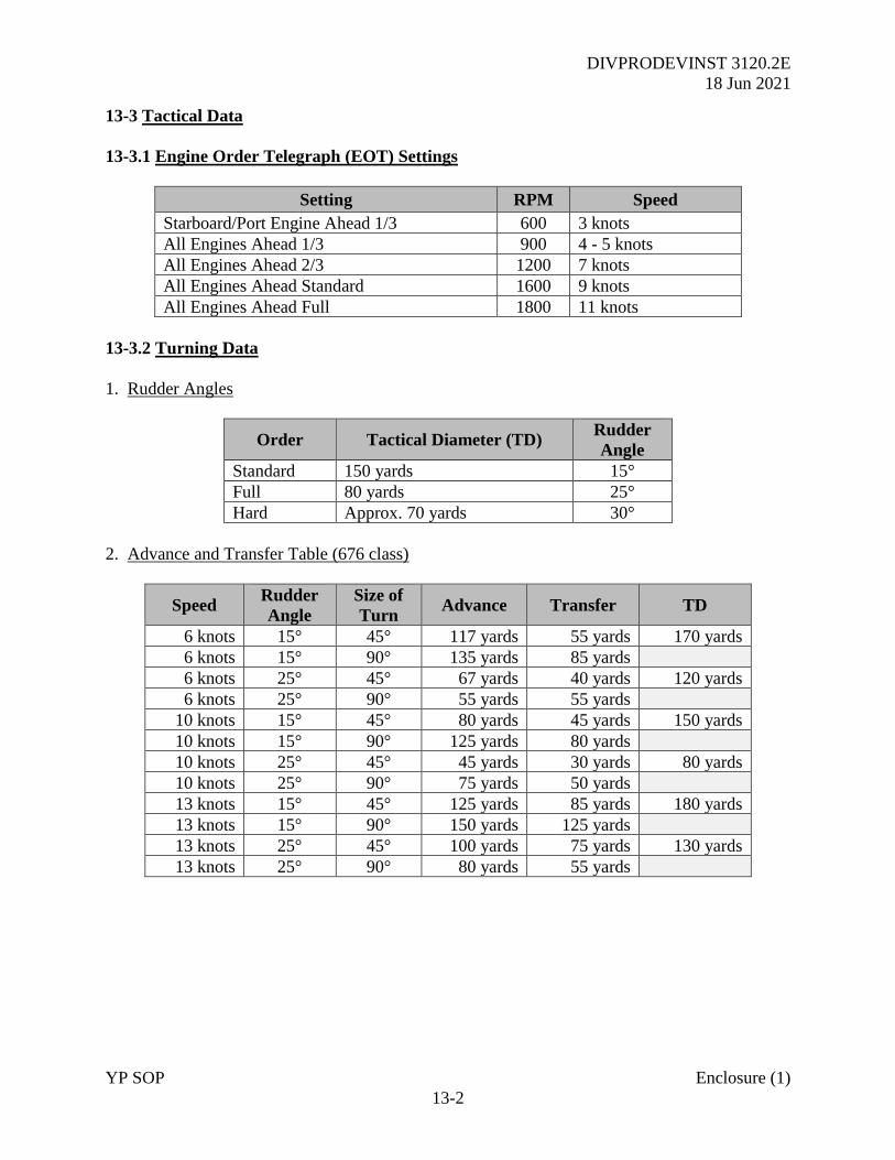
DIVPRODEVINST 3120.2E
18 Jun 2021
YP SOP Enclosure (1)
13-2
13-3 Tactical Data
13-3.1 Engine Order Telegraph (EOT) Settings
Setting RPM Speed
Starboard/Port Engine Ahead 1/3 600 3 knots
All Engines Ahead 1/3 900 4 - 5 knots
All Engines Ahead 2/3 1200 7 knots
All Engines Ahead Standard 1600 9 knots
All Engines Ahead Full 1800 11 knots
13-3.2 Turning Data
1. Rudder Angles
Order Tactical Diameter (TD) Rudder
Angle
Standard 150 yards 15°
Full 80 yards 25°
Hard Approx. 70 yards 30°
2. Advance and Transfer Table (676 class)
Speed Rudder
Angle
Size of
Turn Advance Transfer TD
6 knots 15° 45° 117 yards 55 yards 170 yards
6 knots 15° 90° 135 yards 85 yards
6 knots 25° 45° 67 yards 40 yards 120 yards
6 knots 25° 90° 55 yards 55 yards
10 knots 15° 45° 80 yards 45 yards 150 yards
10 knots 15° 90° 125 yards 80 yards
10 knots 25° 45° 45 yards 30 yards 80 yards
10 knots 25° 90° 75 yards 50 yards
13 knots 15° 45° 125 yards 85 yards 180 yards
13 knots 15° 90° 150 yards 125 yards
13 knots 25° 45° 100 yards 75 yards 130 yards
13 knots 25° 90° 80 yards 55 yards
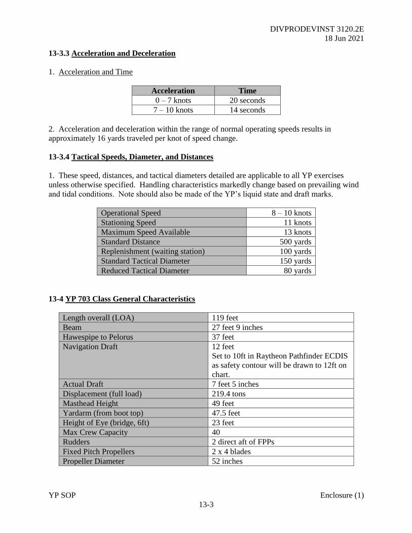
DIVPRODEVINST 3120.2E
18 Jun 2021
YP SOP Enclosure (1)
13-3
13-3.3 Acceleration and Deceleration
1. Acceleration and Time
Acceleration Time
0 – 7 knots 20 seconds
7 – 10 knots 14 seconds
2. Acceleration and deceleration within the range of normal operating speeds results in
approximately 16 yards traveled per knot of speed change.
13-3.4 Tactical Speeds, Diameter, and Distances
1. These speed, distances, and tactical diameters detailed are applicable to all YP exercises
unless otherwise specified. Handling characteristics markedly change based on prevailing wind
and tidal conditions. Note should also be made of the YP’s liquid state and draft marks.
Operational Speed 8 – 10 knots
Stationing Speed 11 knots
Maximum Speed Available 13 knots
Standard Distance 500 yards
Replenishment (waiting station) 100 yards
Standard Tactical Diameter 150 yards
Reduced Tactical Diameter 80 yards
13-4 YP 703 Class General Characteristics
Length overall (LOA) 119 feet
Beam 27 feet 9 inches
Hawespipe to Pelorus 37 feet
Navigation Draft 12 feet
Set to 10ft in Raytheon Pathfinder ECDIS
as safety contour will be drawn to 12ft on
chart.
Actual Draft 7 feet 5 inches
Displacement (full load) 219.4 tons
Masthead Height 49 feet
Yardarm (from boot top) 47.5 feet
Height of Eye (bridge, 6ft) 23 feet
Max Crew Capacity 40
Rudders 2 direct aft of FPPs
Fixed Pitch Propellers 2 x 4 blades
Propeller Diameter 52 inches
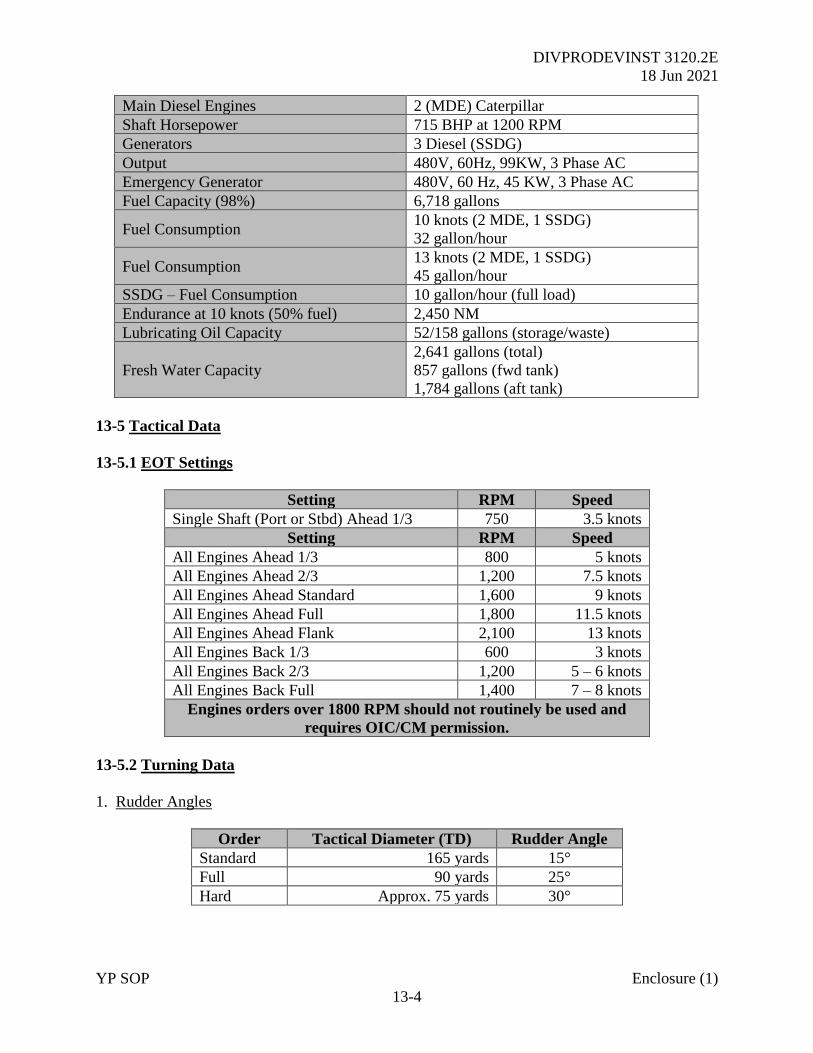
DIVPRODEVINST 3120.2E
18 Jun 2021
YP SOP Enclosure (1)
13-4
Main Diesel Engines 2 (MDE) Caterpillar
Shaft Horsepower 715 BHP at 1200 RPM
Generators 3 Diesel (SSDG)
Output 480V, 60Hz, 99KW, 3 Phase AC
Emergency Generator 480V, 60 Hz, 45 KW, 3 Phase AC
Fuel Capacity (98%) 6,718 gallons
Fuel Consumption 10 knots (2 MDE, 1 SSDG)
32 gallon/hour
Fuel Consumption 13 knots (2 MDE, 1 SSDG)
45 gallon/hour
SSDG – Fuel Consumption 10 gallon/hour (full load)
Endurance at 10 knots (50% fuel) 2,450 NM
Lubricating Oil Capacity 52/158 gallons (storage/waste)
Fresh Water Capacity
2,641 gallons (total)
857 gallons (fwd tank)
1,784 gallons (aft tank)
13-5 Tactical Data
13-5.1 EOT Settings
Setting RPM Speed
Single Shaft (Port or Stbd) Ahead 1/3 750 3.5 knots
Setting RPM Speed
All Engines Ahead 1/3 800 5 knots
All Engines Ahead 2/3 1,200 7.5 knots
All Engines Ahead Standard 1,600 9 knots
All Engines Ahead Full 1,800 11.5 knots
All Engines Ahead Flank 2,100 13 knots
All Engines Back 1/3 600 3 knots
All Engines Back 2/3 1,200 5 – 6 knots
All Engines Back Full 1,400 7 – 8 knots
Engines orders over 1800 RPM should not routinely be used and
requires OIC/CM permission.
13-5.2 Turning Data
1. Rudder Angles
Order Tactical Diameter (TD) Rudder Angle
Standard 165 yards 15°
Full 90 yards 25°
Hard Approx. 75 yards 30°
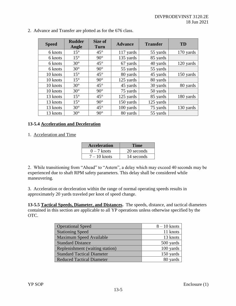
DIVPRODEVINST 3120.2E
18 Jun 2021
YP SOP Enclosure (1)
13-5
2. Advance and Transfer are plotted as for the 676 class.
Speed Rudder
Angle
Size of
Turn Advance Transfer TD
6 knots 15° 45° 117 yards 55 yards 170 yards
6 knots 15° 90° 135 yards 85 yards
6 knots 30° 45° 67 yards 40 yards 120 yards
6 knots 30° 90° 55 yards 55 yards
10 knots 15° 45° 80 yards 45 yards 150 yards
10 knots 15° 90° 125 yards 80 yards
10 knots 30° 45° 45 yards 30 yards 80 yards
10 knots 30° 90° 75 yards 50 yards
13 knots 15° 45° 125 yards 85 yards 180 yards
13 knots 15° 90° 150 yards 125 yards
13 knots 30° 45° 100 yards 75 yards 130 yards
13 knots 30° 90° 80 yards 55 yards
13-5.4 Acceleration and Deceleration
1. Acceleration and Time
Acceleration Time
0 – 7 knots 20 seconds
7 – 10 knots 14 seconds
2. While transitioning from “Ahead” to “Astern”, a delay which may exceed 40 seconds may be
experienced due to shaft RPM safety parameters. This delay shall be considered while
maneuvering.
3. Acceleration or deceleration within the range of normal operating speeds results in
approximately 20 yards traveled per knot of speed change.
13-5.5 Tactical Speeds, Diameter, and Distances. The speeds, distance, and tactical diameters
contained in this section are applicable to all YP operations unless otherwise specified by the
OTC.
Operational Speed 8 – 10 knots
Stationing Speed 11 knots
Maximum Speed Available 13 knots
Standard Distance 500 yards
Replenishment (waiting station) 100 yards
Standard Tactical Diameter 150 yards
Reduced Tactical Diameter 80 yards
DIVPRODEVINST 3120.2E
18 Jun 2021
YP SOP Enclosure (1)
14-1
CHAPTER 14
YP BRIDGE MANNING AND ORGANIZATION
14-1 Introduction. As described in Chapter 2, the OIC and CM must organize the navigation
team in an appropriate manner to meet the demands and complexities of the mission while
maintaining an effective learning environment. The organization of the Navigation Team will be
dependent on the mission of the YP, especially if deploying Out of Area. Where necessary,
personnel under training will be rotated through positions to maximize learning.
14-2 Local Area Operations in the Severn River and Approaches
1. YPs may operate in the Local Operating Area with a minimum crew of Waterfront Enlisted
personnel to deliver tasks including craft trials and maintenance. The following personnel are
required as a minimum:
a. A qualified Craftmaster (CM)
b. Two YP enlisted crewmembers
c. A YP Engineer
2. If operating for a prolonged period in restricted waters, the watch composition must be such
to enable basic safe navigation procedures to be applied. For example, if transiting in the
Chesapeake, a proper fix must be taken electronically to verify ECDIS / VMS and GPS accuracy
at a minimum period of 15 minutes. While routine transits between the WFR Basin and Dewey
Seawall may be undertaken with a minimum crew, careful consideration should be given to more
complicated tasking and the requirement to enhance teams with additional qualified personnel.
3. In these instances, sufficient, trained personnel should be available to provide two
watchstanders on the bridge, thus enabling maintaining a proper lookout and fixing routine while
driving the YP.
4. WFR Enlisted Crews should aspire to build strength in depth amongst their teams. For
example, locally qualifying enlisted deck hands as Helmsman will enable CMs to stand back and
affect bridge resource management. This is essential at times such as when operating in high
traffic density, at night or where there is risk of reduced visibility. For example, in fog, the CM
must be able to constantly monitor navigation and anti-collision from the Radar, Chart and
ECDIS / VMS. This cannot be achieved from the Panish.
14-2.1 Midshipmen Watchstanders
1. When conducting training operations with Midshipmen embarked, qualified crew are to
provide the following watchstanding positions at all times:
a. At least 1 OIC, AOIC, or CM on the Bridge at all times.
DIVPRODEVINST 3120.2E
18 Jun 2021
YP SOP Enclosure (1)
14-2
b. One YP enlisted crewmember to conduct safety rounds as required.
c. The CHENG or a nominated engineer who does not need to be on station in the engine
room, but must be immediately available to investigate any alarm.
2. The Midshipmen Sea and Anchor Detail will comprise the following watchstanding positions
with the organization detailed at figure 14.1 and responsibilities as described in Chapter 2. This
may be modified to the environment as detailed at the table below.
a. Officer of the Deck (OOD)
b. Conning Officer (Conn)
c. Assistant Navigator (ANAV)
d. Plotter.
e. Bearing Book (BB) Recorder.
f. Bearing Taker/Lookout(s).
g. Radar Operator.
h. Helmsman
i. Lee Helmsmen - In 703 Class may be combined with Helm at OIC/CM discretion.
j. Midshipman Engineering Operating Station (EOS) Watch.
Distance from Shoal
Water
Restricted Waters All other
Less than 1NM 1 – 10 NM
OIC Note Note
CM Note Note
AOIC Note Note
Plotter Yes Yes
Bearing Recorder Yes No
Radar Operator Yes Yes
Port Bearing Taker Yes No
Starboard Bearing Taker Yes No
Lookout Yes Yes
Note: In restricted waters, two qualified personnel in any combination of OIC, AOIC or CM
must be on the bridge. One is to oversee safe navigation with the other responsible for
overall safety. Outside of 1nm from land, only 1 of 3 shall be on watch.
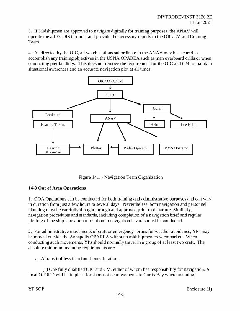
DIVPRODEVINST 3120.2E
18 Jun 2021
YP SOP Enclosure (1)
14-3
3. If Midshipmen are approved to navigate digitally for training purposes, the ANAV will
operate the aft ECDIS terminal and provide the necessary reports to the OIC/CM and Conning
Team.
4. As directed by the OIC, all watch stations subordinate to the ANAV may be secured to
accomplish any training objectives in the USNA OPAREA such as man overboard drills or when
conducting pier landings. This does not remove the requirement for the OIC and CM to maintain
situational awareness and an accurate navigation plot at all times.
Figure 14.1 - Navigation Team Organization
14-3 Out of Area Operations
1. OOA Operations can be conducted for both training and administrative purposes and can vary
in duration from just a few hours to several days. Nevertheless, both navigation and personnel
planning must be carefully thought through and approved prior to departure. Similarly,
navigation procedures and standards, including completion of a navigation brief and regular
plotting of the ship’s position in relation to navigation hazards must be conducted.
2. For administrative movements of craft or emergency sorties for weather avoidance, YPs may
be moved outside the Annapolis OPAREA without a midshipmen crew embarked. When
conducting such movements, YPs should normally travel in a group of at least two craft. The
absolute minimum manning requirements are:
a. A transit of less than four hours duration:
(1) One fully qualified OIC and CM, either of whom has responsibility for navigation. A
local OPORD will be in place for short notice movements to Curtis Bay where manning
OIC/AOIC/CM
Plotter
Lookouts
Helm Lee Helm
Bearing
Recorder
OOD
VMS Operator
ANAV
Conn
Bearing Takers
Radar Operator
DIVPRODEVINST 3120.2E
18 Jun 2021
YP SOP Enclosure (1)
14-4
requirements may be reviewed, with approval by PRODEV and recommendations from
SEANAV and WFR Director.
(2) One trained Helmsman for Ship Control who may be an enlisted Crewman or other
OIC/CM.
(3) Two YP enlisted crewmembers
(4) A YP Engineer
b. A transit of greater than four hours duration:
(1) For transits over 4 hours, three qualified personnel comprising 1 x OIC, 1 x AOIC
and 1 x CM or 1 x OIC and 2 x CMs.
(2) When transiting restricted waters, two of the three personnel shall be on the bridge
with one formally assigned responsibility for anti-collision and the other navigation.
(3) A trained Helmsman for Ship Control.
(4) An additional YP Engineer to ensure that an “on watch” Engineer is always available.
(5) Within the Squadron, comprising of two or more ships:
(a) An Electronic Technician (ET)
(b) An Electrician’s Mate (EM)
(c) A minimum of one Corpsman (HM). Two or more if available.
4. If these requirements cannot be met, for whatever reason, inform SEANAV, WFR, and
PRODEV prior to submission of the OPORD.
DIVPRODEVINST 3120.2E
18 Jun 2021
YP SOP Enclosure (1)
15-1
CHAPTER 15
DIGITAL, PAPER CHART AND PUBLICATION POLICY
15-1 Standards
1. Timely maintenance of digital and paper charting and publications is critical to safe planning
and execution of navigation underway, whether in vicinity of the USNA or outside of the
Operating Area. All OICs and CMs are to understand chart maintenance requirements and must
be able to check the currency of paper and digital products as part of the qualification process
and prior to getting underway for tasking.
2. Typically, all charts and publications should be corrected for Notice to Mariners within 5
weeks of tasking. OICs and CMs should then check USCG Local Notice to Mariners for any
corrections that might be pertinent after the last dated Notice to Mariner.
3. If YPs chart and publication holdings do not meet these standards prior to getting underway,
approval from SEANAV is required to sail.
15-2 Publications
1. The following, corrected publications shall be on board all YPs at all times. These may be
held as a digital or hard copy as required.
a. NOAA Tide Tables, East Coast of North and South America. (Hard Copy Only)
b. Light List Volume 2, Toms River, NJ to Little River, SC.
c. Coast Pilot 3, Atlantic Coast; Sandy Hook, New Jersey to Cape Henry, Virginia.
d. Radio Navigation Aids (Provided through the NGA).
e. USCG Navigation Rules and Regulations Handbook (Rules of the Road). (Hard Copy
Only)
f. Chart Number 1, Nautical Chart Symbols.
g. USNA Multi-national Tactical Publication (MTP) 1D Vol 1.
h. USNA Multi-national Tactical Publication (MTP) 1D Vol 2. (Hard Copy Only)
i. YP Standard Operating Procedures. (Hard Copy Only)
2. The SEANAV Chart Room is responsible for providing Waterfront Readiness with updated
digital publications on a monthly basis. These are to be retained electronically on board each YP
to enable quick access and reference when underway as required.
DIVPRODEVINST 3120.2E
18 Jun 2021
YP SOP Enclosure (1)
15-2
3. Hard copy publications are to be ordered and updated, when not held electronically, in liaison
with SEANAV Chart Room.
4. Additional publications for Out of Area operations will be listed in the OP Order. These
should be held and maintained digitally wherever possible. If required in hard copy, this must be
requested through the Chart Room at the earliest opportunity.
15-3 Paper Chart Requirement. The 703 Class are fitted with Raytheon Pathfinder ECDIS and
the 676 Class with ECDIS-N Voyage Management System software. However, neither are
certified for Digital Navigation in accordance with the International Maritime Organization
equipment and training standards and therefore must carry a full outfit of paper charts covering
the area of operations.
15-3.1 Paper Chart Requirements for Local Operations
1. YPs are to carry an approved folio of charts provided by SEANAV that cover the Local
Operations Area to include the Severn River and adjoining Chesapeake Bay (Charts 12283,
12282 and 12270). These will be drawn up with arrival and departure tracks and danger bearings.
These charts must be sighted and certified by OICs and CMs before getting Underway.
2. These charts are to have been corrected within 5 weeks. OICs and CMs are to check charts
prior to getting underway to ensure they are familiar with any corrections or changes that may
impact the local area. If charts are not corrected to within 5 weeks of the date of the activity, the
YP should not proceed underway.
3. Charts used for navigational safety purposes are to be prepared in accordance with the Chart
Preparation Checklist in Appendix E. They will be signed as checked by the OIC/CM
responsible for the period underway in the Ship Log.
4. For SEANAV labs, midshipmen will utilize Chart 12283 provided by the instructor for
training purposes. These will not be corrected to the latest Notice to Mariner, hence the
requirement for YPs to hold corrected charts.
15-3.2 Paper Chart Update Procedure for Local Operations
1. Notice to Mariners and Local Notice to Mariners must be applied correctly to paper charts to
ensure safe navigation.
2. 2 Sets of Local Charts are to be held available for each YP. 1 set, corrected within 5 weeks of
operations, is to be held on the YP. The 2nd set will be held in the Chart Room for update. The
OIC / CM are responsible for checking Local Notice to Mariners or Navigation Warnings
recently released that affect the Local Area. Where necessary, these should be plotted onto the
chart.

DIVPRODEVINST 3120.2E
18 Jun 2021
YP SOP Enclosure (1)
15-3
3. At the start of each month, Chart sets will be rotated. SEANAV Enlisted Division is
responsible for updating the local folios fully before passing them the WFR for use, at which
point returned charts are to be updated. The details of this process can be found at Enclosure 3.
15-3.3 Paper Chart Requirements for Deployed Operations
1. Deploying out of area for routine MOs or LANTPAT, YPs are to carry a full set of paper
charting covering the area of anticipated operations.
2. The MO assigned Navigating Officer is responsible for planning the MO / LANTPAT
navigation plan. They are to liaise early with the SEANAV Chart Room to ensure the appropriate
charts, covering the area of operations, are ordered and received in good time.
3. MIDN and YPRON should be involved in the Navigation Planning process wherever
possible. However, responsibility for accuracy of drawn up charts and associated corrections
rests with the Staff Navigator. This includes all updates of Local Notice to Mariners and Notice
to Mariners to ensure the charts are corrected to the most accurate state.
4. Once planned and corrected, the SEANAV Chair will authorize and sign all paper charting.
This may be delegated as required, but only once approved should charts then be copied and
reproduced for multiple YPs proceeding on the tasking.
5. Charts to be used must be prepared in accordance with the Chart Preparation Checklist in
Appendix E. The OIC and CM remain responsible for checking charts prior to getting
underway, including ensuring that the most recent chart corrections have been applied.
15-4. Navigational Safety Warning Messages. When transiting or conducting training outside
of the Annapolis OPAREA, OIC/CMs should review posted safety warning messages daily. The
following methods should be used:
a. NAVTEXT is part of the Global Maritime Distress Safety System and should be set to
receive Navigation Warning messages from local stations in the area of planned operations.
NAVTEXT equipment should be checked with every watch changeover, with new messages
impacting the area of operations applied to charts as necessary.
b. The OIC/CM can also use the Coast Guard website (www.navcen.uscg.gov) to view
special warnings and advisories for the area they are operating in.
c. Other useful government websites include National Oceanic and Atmospheric
Administration (NOAA) including Tides and Currents (www.tidesandcurrents.noaa.gov) and the
National Weather Service (www.weather.gov/forecastmaps).
d. Routinely, the SEANAV Chart Room will collate navigation advisory notices and NTM
and forward the appropriate information to the deployed OTC.
DIVPRODEVINST 3120.2E
18 Jun 2021
YP SOP Enclosure (1)
15-4
15-5.1 Electronic Chart Requirements for Local Operations
1. NGA-supplied DNCs H1708225 and A1708225 must be displayed on VMS. NOAA-supplied
ENCs US5MD22M, US5MD32M and US5MD31M must be displayed on ECDIS.
2. In the local area, OICs and CMs will navigate visually primarily due to their familiarity with
the Local Op Area. Therefore, ECDIS / VMS is to be used to support their Situational Awareness
hence the requirement to fix and validate the YP’s position on ECDIS/VMS every 15 minutes.
The latest Vector Data Updates (VDUs) should be applied but paper charting remains the
approved means of navigation. OICs / CMs are to ensure they understand the update state of
electronic charts and any subsequent differences to corrected paper charts.
15-5.2 Electronic Chart Updates
1. The SEANAV Chart Room is responsible for providing electronic updates to DNCs to WFR.
These are to be applied over a period not exceeding 5 weeks. Should electronic charts on both
ECDIS / VMS terminals not be updated to within 5 weeks, the YP shall revert to paper
navigation only.
2. Electronic Chart updates are to be recorded centrally between SEANAV and WFR to ensure
the status of YP systems are understood.
3. OICs and CMs are to check the update status of electronic charts before getting underway,
ensuring that any discrepancies with updated paper charts are understood. As necessary, manual
corrections can be applied to the charts through Navigation Layers.
DIVPRODEVINST 3120.2E
18 Jun 2021
YP SOP Enclosure (1)
16-1
CHAPTER 16
YP NAVIGATION POLICY AND PROCEDURES
16-1 Standards
1. Safe and effective planning is critical to mission success. Adherence to the planning
procedures detailed in the references, with appropriate supervision by qualified personnel, is
essential especially where MIDN, who are not qualified in navigation, are involved in the
planning process. Therefore, the nominated OTC, OICs and CMs are to take the time and effort
necessary to check and double check that navigation planning, including preparation of charts, is
conducted to the expected standard.
2. Similarly, when underway, proper standards of watchkeeping must be maintained within the
organization of the training environment. If the OIC or CM is in doubt at any time, STOP. Put
the YP into a safe position and re-assess and if necessary re-plan.
16-2 Navigational Draft
1. Based on the characteristics of both 676 and 703 class YPs, the 12-foot contour is to be used
as the minimum (shallow) navigation safety contour for planning purposes at all times.
2. In the 676 Class, the safety depth is set to 11.8ft in VMS due to the way in which the contour
is drawn on installed Digital Nautical Charts (DNCs).
3. In the 703 Class, the safety depth is set to 10ft in Raytheon Pathfinder due to the way in
which contour is drawn on installed Electronic Nautical Charts (ENCs).
16-3 Navigation Planning - Local Area Operations
1. For local area operations, MIDN, under the direction of instructors, will provide charts for
training purposes. These will not necessarily be navigationally safe hence the requirement for all
YPs to hold properly drawn up and corrected Local Area charting in accordance with Appendix
E.
2. The routes applied to YP safe navigational paper charts are to be reproduced fully on ECDIS /
VMS in support of Situational Awareness for CMs and Instructors during local training. There
should be no difference between the two plans.
16-4 Navigation Planning - Out of Area Operations
1. For OOA operations, the OTC is responsible for the supervision and safety of navigation
planning and must provide initial guidance on the mission and training objectives to planning
staff involved.
DIVPRODEVINST 3120.2E
18 Jun 2021
YP SOP Enclosure (1)
16-2
2. A Plan of Action and Milestones (POAM) is to be created, detailing the timeline for planning,
ensuring sufficient opportunity is provided for charts to be drawn and copied.
3. The Staff Navigator and Midshipman Navigator are to create an initial navigation plan
digitally using a VMS that has been updated to within 5 weeks. The paper chart requirement is to
be identified and submitted to the SEANAV Chart Room at the earliest opportunity so that they
may be ordered and corrected as necessary. The dates required are to be listed on the POAM.
The navigation plan should also include detail such as Speed of Advance and Ephemeral data.
4. The Staff Navigator and MIDN Navigator are to present the navigation plan to the OTC. This
should include detailed information from the appropriate Coastal Pilot and other publications as
necessary. At the end of this brief, the OTC is to either direct further changes to the plan or
Approve the plan, for final endorsement by SEANAV or a delegated officer.
5. Once the initial route has been approved digitally by SEANAV, the waypoints and other
critical information can be transferred to paper charts and prepared in accordance with Appendix
E. Paper Charts are to have been updated for Notice to Mariners and Local Notice to Mariners.
6. Once chart preparations are completed, the OTC is responsible for inspecting all charts before
presenting the final navigation plan to SEANAV or a delegated authority who will sign the
charts as approved. At this point, the charts can be copied as necessary to ensure each craft
deploying has a full set of approved charts.
7. As the 703 Class are fitted with Raytheon Pathfinder and not VMS, the approved route is to be
created and transferred to each craft deploying.
8. OICs and CMs remain responsible for checking both paper and digital navigation routes to
ensure all corrections are properly applied before getting underway and that the navigational plan
is safe for their mission.
16-5 Transit and Navigation Briefs
1. Transit Brief. A Transit Brief is required for all OOA Operations, presented by the Staff or
MIDN Navigators to the OTC and Deputy Commandant of Professional Development and/or
Chairman of the Department of Seamanship and Navigation no more than 72 hours prior to any
underway outside the Annapolis operating area. This is a “strategic-level” voyage overview of
the speed – time – distance challenge and may cover an extended duration, with intervening Port
Visit and an overview of areas of restricted waters to be navigated. The basic format for the
brief should be as detailed at Appendix I.
2. When already deployed, Transit Briefs between ports must be presented to the OTC.
3. Navigation Brief. Before getting underway for any activity, including local area operations, a
Navigation Brief is to be conducted within 24 hours of departure pier side using the format
detailed at Appendix I.
DIVPRODEVINST 3120.2E
18 Jun 2021
YP SOP Enclosure (1)
16-3
4. In contrast to the transit brief, this is the watch team’s opportunity to focus on track data in
detail for the specific area to be navigated.
5. Points for discussion include Weather, Area of Operations, movements and traffic density,
ephemeral data including tides and YP status including casualties / defects and Operational Risk
Matrix (ORM).
16-6 Pre-Underway Checks
1. Prior to getting underway, the OIC/CM are to ensure all equipment and planning checks are
completed in accordance with SOP Section 4. Shortfalls are to be reported to WFR and
SEANAV for approval to conduct local operations or deploy OOA.
2. For training purposes, Midshipmen may conduct the reduced checklist when the fully
approved checklist has been completed by the OIC/CM for the day’s training.
16-7 Fixing Interval Requirements with A Functional ECDIS System
1. An internationally certified ECDIS system requires a networked capability between systems.
The US Navy ECDIS-N policy requires fusion of external sensors such as radar. Neither the 676
or 703 Classes currently meet these technical requirements to fully enable digital navigation
alone hence the requirement for YPs to carry fully corrected and prepared paper charting as a
backup should the system fail. Therefore, the ability of OICs, AOICs and CMs to be able to
apply a visual, radar or composite fix to a paper chart or ECDIS system is a fundamental skill
that enables safe navigation.
2. Although not digitally certified for electronic navigation, VMS (676) and Raytheon Pathfinder
(703) may be used as the primary plot for navigational safety. However, this requires that the
systems position be validated, at an interval of not more than 15 minutes. When in constrained
waters, or if in any doubt, this interval may be reduced as required by the OIC or CM. When in
sight or radar range of land, this validation should be by a visual or radar LOP. GPS should not
be used to validate the system unless out of the sight of land.
3. Prior to getting underway, a Visual / GPS is to be plotted on ECDIS / VMS and paper
charting. This is to enable identification of any Gyro / Radar error and to prove the ECDIS
system correct as detailed in the Underway Checklist.
4. Local Area Operations. CMs in particular, build a level of local navigation knowledge similar
to a Pilot. As such, they will routinely navigate the ship in the Severn River visually, enabling
Midshipmen training to continue uninterrupted. When operating in the Severn River, a visual or
Radar LOP should be taken periodically to ensure that the GPS position in VMS / ECDIS is
correct. However, should there be any doubt in regards to position, training is to be ceased and
the craft’s position fixed immediately.
DIVPRODEVINST 3120.2E
18 Jun 2021
YP SOP Enclosure (1)
16-4
5. When operating in the Chesapeake Bay, but within the Local Operating Area, fixes are to be
applied electronically, at a period that meets the situation but at an interval of not more than a 15
minute, to prove ECDIS or VMS correct.
8. Out of Area Operations. To enable the USNA training mission, Midshipmen or USNA Staff
Under Instruction will run a paper chart for training purposes. These charts will have been
properly corrected, prepared and certified through SEANAV. While all efforts should be made to
fix at the required frequencies described in the references, manning or experience can prevent
these requirements from being achieved. Provided VMS / Pathfinder has been validated at an
interval not exceeding 15 minutes, failure to meet paper chart fixing requirements does not mean
the YPs position is unknown. However, if there are any major discrepancies between electronic
and paper navigation, OICs and CMs must be of the mindset that if in doubt about position, they
are to slow or stop the ship and to fix accordingly.
16-8. Loss of ECDIS Capability - Reversion to Paper Charting
1. As electronic systems, VMS and Pathfinder rely on inputs from other systems in order to
provide accurate positional information. External factors, such as loss of GPS reception or
interruptions to the YPs power supply may cause a loss of system inputs into the ECDIS system.
2. USNA and WFR OICs, AOICs and CMs may not be qualified to the US Navy’s full OPNAV
Instruction requirements. Although formalized, local training through the Job Qualification
Requirement process will be provided by SEANAV, this cannot replace the IMO approved
course requirements. As such, personnel are neither trained or certified in the use of ECDIS
systems in reversionary modes when inputs such as GPS become unavailable.
3. To that end, any loss of ECDIS capability, including inputs to the system that support
navigational positioning, constitute an emergency and render the YP Non-Mission Capable until
the ECDIS capability is restored. If this occurs when underway, this requires immediate
reversion to paper navigation as the primary plot. This is why all OICs, AOICs and CMs must be
able to plot LOPs and DRs on paper charts, especially when in unfamiliar waters deployed OOA.
4. Fix Interval. When using paper charts as the primary plot due to a loss of the ECDIS
capability, the table below outlines the navigation standards for paper fixing intervals.
5. As this situation constitutes a navigation emergency, qualified OICs, AOICs and CMs must be
involved in the fixing process to ensure accurate positioning and DRs to maintain navigationally
safety until alongside. Midshipmen or Staff Under Instruction may support the navigation
organization but the OIC remains fully responsible for navigational safety.
Area Distance from Land/Shoal Water Required Fix Interval
Restricted Waters less than 1nm (2,000 yards) 3 minutes
Piloting Waters 1 – 10nm 6 minutes
Coastal Waters 10 – 20nm 12 minutes
Open Ocean greater than 20nm 15 minutes
DIVPRODEVINST 3120.2E
18 Jun 2021
YP SOP Enclosure (1)
16-5
6. When transiting areas such as the Chesapeake and Delaware Canal, where an accurate DR
cannot be maintained, fixes are to be placed at a sensible periodicity as agreed by the OIC.
16-9. Operating in Restricted Visibility
1. When visibility reduces to 2,000 yards or less, the OIC/CM and assigned watch standers will
execute the Low Visibility Checklist in Appendix K. Depending on traffic density and the safe
water, the OIC or CM should consider adding additional qualified watchstanders to ensure Ship
safety.
2. In this situation, the Ship’s position is to be constantly monitored and checked against Radar
and conspicuous marks. ECDIS or VMS is to be verified using Radar as the primary means of
LOP. In the event of the loss of ECDIS capability, fixing should be reverted to paper charting
with radar plotting using range and bearing maintained at the required fixing interval to validate
ECDIS. GPS should only be used to validate position as a last resort.
16-10. Fixing Methods
1. Whilst ECDIS may be used as the Primary Plot, the USNA training mission requires OICs,
AOICs and CMs to support Midshipmen and Staff Under Instruction to identify and use varying
types of fixing aid. Types of approved fix in order of priority include:
a. Visual fix, annotated on the chart using a circle around the plotted position.
b. Radar fix, annotated on the chart using a triangle around the plotted position.
c. Electronic fix (GPS), annotated on the chart using a triangle around the plotted position.
This should only be used out of the sight of land. Visual and Radar LOPs are to be the primary
means of navigation.
d. Composite fix, a combination of visual and electronic data annotated by a triangle.
2. The appropriate fixing combination is dependent on the operating area, prevailing weather,
visibility and proximity to navigation hazards. It is the responsibility of the OIC and CM to
determine and supervise the navigation team in the correct use of all available fixing sources; a
single source of information is not to be relied upon solely.
Note: If the midshipmen navigation team is unable to fix the YP’s position for two consecutive
fix intervals, the OIC/CM will immediately plot a GPS fix on the chart to verify position.
3. Assessment of Position by Other Means. All means available should be used to determine and
update the YP’s position, as much to prove the validity of the ECDIS system in use. Due to the
nature of MIDN training however, fixes may not be applied in a timely or accurate manner and
therefore additional means should be used to prove the YP’s position including:
a. Parallel Index lines on radar to determine distance off of track.
DIVPRODEVINST 3120.2E
18 Jun 2021
YP SOP Enclosure (1)
16-6
b. Close watch of the fathometer, especially in shoal waters.
c. Preplanned head or stern bearings at known ranges to allow accurate appraisal position
relative to planned track.
d. Seaman’s eye - estimated position relative to positively identified aids to navigation and
prominent landmarks such as bridges, structures, or geographic features.
e. The disposition of the buoy field should not be relied upon unless the positions of the
buoys and other marks have been checked to be in the correctly charted positions.
4. Anytime the OIC/CM has fewer than two independent sources of information confirming the
position of the YP or if available information sources conflict as to the YP’s position, the
OIC/CM shall assume the YP is in possible danger. Take all way off (as wind, tidal stream, and
traffic conditions permit), suspend training, and focus on regaining an accurate navigation
picture before proceeding.
16-11. Dead Reckoning (DR)
1. DR determines future position by plotting the ordered course and speed from the last fix. It
does not consider any influencing factors such as tidal stream or wind. A DR plot must be
maintained and plotted using the six rules below.
a. At every course change.
b. At every speed change.
c. When obtaining a fix or running fix.
d. When obtaining a single Line of Position (LOP).
e. Plot and label a DR position with course, speed, and time along with a new course line
from each fix or running fix. This should be plotted whether the craft is on track or not. The DR
plot will show the next two fix intervals.
f. Plot a position at least every hour, on the hour.
2. Set and Drift. Set and drift shall be calculated at least every third fix interval and more
frequently when the plotter’s proficiency and work rate permit. Check both course and speed
made good to ensure it is what is intended and compensate as required. When using
VMS/ECDIS, frequent comparison of heading, course over ground, and speed over ground shall
be made and appropriate compensation applied.
3. The nearest hazards to navigation must be known at all times.
DIVPRODEVINST 3120.2E
18 Jun 2021
YP SOP Enclosure (1)
16-7
4. The direction towards open/safe water along the track must be known at all times.
16-12. Use of A Fully Functional VMS and ECDIS.
1. For operations involving Midshipmen, paper charts shall continue to be used to deliver the
training mission. This means that navigation reports provided from the paper chart may be
inaccurate. The OIC, AOIC or CM will therefore use ECDIS to evaluate the accuracy of
navigation reports as well as providing improved situational awareness to the supervisory
personnel.
2. VMS/ECDIS Configuration. A properly configured VMS or Raytheon Pathfinder ECDIS is
required prior to getting underway using the settings found in Appendix G and H. Incorrectly
configured systems will introduce hazards and safety critical issues. Upon completion of the
checklist, the OIC/CM should annotate it in the deck log.
3. VMS/ECDIS fix intervals. Using VMS or ECDIS, the ship’s vector shall be selected to
indicate a period of at least two fix intervals (e.g. six minutes when in waters requiring a three-
minute fix). Track history shall be enabled and show at least 90 minutes of YP movement.
4. Positioning. VMS/ECDIS will display the position, course, and speed from the selected GPS
source at an update rate of approximately 10 Hz. At each paper fix or on passing a conspicuous
navigation aid, VMS/ECDIS should be verified visually to ensure the accuracy of the navigation
report. This does not change the requirement to physically validate the system with an inputted
LOP at an interval not exceeding 15 minutes.
16-13 Midshipmen Standards of Navigation during Training
1. Midshipmen are always to be considered Under Instruction with their experience and
knowledge below the standard required for safe navigation and will frequently lose track of
position. This is why OICs / CMs must maintain their Situational Awareness at all times.
2. While Midshipmen navigation should aspire to maintain proper fixing intervals and standards,
they must also be encouraged to remain honest, informing the wider team if they lose track of
position. If they do not have a fix at the required interval, they shall immediately report,
“navigation has no fix” while working to establish position. The OIC/CM must ensure a correct
fix is plotted and no more than two fix intervals expire. If necessary, training is to be suspended
in order to slow or stop the craft to facilitate plotting a good fix with support by the OIC/CM to
assist training objectives.
3. The YP navigation team must satisfy the following requirements.
a. Charts prepared in accordance with the Chart Preparation Checklist in Appendix E.
b. Prepare a navigation brief prior to every underway outside the Annapolis OPAREA and
other underway evolutions as directed by the OIC/CM.
DIVPRODEVINST 3120.2E
18 Jun 2021
YP SOP Enclosure (1)
16-8
4. All fixes shall utilize no less than three visual or radar lines of position (LOP) or a
combination of visual and radar LOPs. For training purposes, GPS fixes are only to be used
when visual/radar fixes are unavailable, considered unreliable or to verify or augment
visual/radar fixes. GPS should not to be used as the only source of information.
5. The navigation team will plot, label, and DR in accordance with the established “six rules of
DR.”
6. After plotting each fix and DR, the navigator will provide a navigation report in accordance
with Appendix J. This is to include a “safe water” or “danger” call based on the results of the fix.
The navigation team must assess the YP’s position and determine if the current course leads to
waters not safe for navigation. If so, announce “Danger” ensuring the OIC, CM, OOD, and
CONN all correctly acknowledge the report. If the current course leads to waters safe for
navigation, announce “Safe Water”.
7. For each fix, an assessment of set and drift should be made and compensated for as required.
Check course and speed made good to ensure it is what is intended. Consistently review the
track and always know the nearest hazards to navigation. Always know the direction towards
open/safe water along the track.
8. Remember that while training will focus on developing proficiency in plotting GPS fixes and
visual and radar LOPs, the purpose of navigation is to integrate all resources to fix your position
as accurately as you can.
9. The Bridge Teams are to ensure all other required administration is attended to including
energizing navigation lights between sunset and sunrise and during periods of reduced visibility
and ensuring the bearing book and ship’s position log are accurate and up to date.

DIVPRODEVINST 3120.2E
18 Jun 2021
YP SOP Enclosure (1)
SECTION 4
EQUIPMENT AND ENGINEERING
DIVPRODEVINST 3120.2E
18 Jun 2021
YP SOP Enclosure (1)
17-1
CHAPTER 17
EQUIPMENT REQUIREMENTS
17-1 YP Safety. Understanding material state is critical to craft safety and the unavailability of
key equipment may impact ability to achieve the mission. It is essential therefore that equipment
is thoroughly checked to be operating correctly so that if a defect or casualty is discovered, the
risk can be effectively balanced and mitigated to achieve safe operations. OICs and CMs must
ensure they understand Mission Capability prior to getting underway and then at all times
underway as casualties inevitably occur. If Out of Area, the OTC is to be kept fully informed.
17-2 Mission Capability
1. Due to the transient nature of YP operation, including routine changes of personnel, the
proper and thorough completion of equipment checklists is essential to identifying and reporting
defects or casualties enabling assessment of YP Mission Capability. These checks also prove that
the proper equipment is held, functional and ready for mission tasking prior to proceeding to sea.
2. Equipment Requirements Matrix. Individually, material shortfalls, defects or casualties might
be easily mitigated. However, where multiple issues arise across different systems, cumulative
effect and associated risk may be far greater than when assessed in isolation. When defects or
casualties occur, the tables at appendix L and M may be used to determine YP suitably for
operations. If a YP falls short of the required material standard, SEANAV, WFR, and PRODEV
are to be informed and mitigation approved before tasking may be executed.
3. YPs may be categorized as:
a. Fully Mission Capable (FMC) - Navigation, propulsion, habitability, and safety equipment
is fully functional and supports all OOA operations and local area requirements.
b. Partially Mission Capable (PMC) – Degradation of navigation, propulsion, habitability,
and safety equipment prevents OOA operations but likely supports Local Area requirements.
Local and OOA operations shall be conducted only after having received a WFR DIR approved
waiver for each material degradation. This can be received by verbal means or message and shall
be recorded in the deck log. If OOA, SEANAV and PRODEV are also to be consulted for
approval by the OTC.
c. Non-Mission Capable (NMC) – Major casualty to one or more systems prevents the craft
from being operated safely. Basin movements shall be conducted to support maintenance and
casualty repairs only after having received a WFR DIR approved waiver. In the event multiple
degradations exist, a WFR DIR approved waiver is required for each NMC degradation. This can
be received by verbal means or message and shall be recorded in the deck log.
17-3 Underway and Equipment Checks
DIVPRODEVINST 3120.2E
18 Jun 2021
YP SOP Enclosure (1)
17-2
1. Underway equipment checks are critical to assessing YP Mission Capability. The Underway
Checklist detailed at Appendix N is to be completed thoroughly and to a high standard prior to
departing the slip. Any shortfall from Underway checklists are to be included in Ready for Sea
reports to the OTC prior to deploying Out of Area.
2. Master Light Off Checks (MLOCs). These checks are critical to the safe operation of both
machinery and the YP as a whole. OICs and CMs must be equally familiar with the process,
ensuring the supervise, support and critique checks on a regular basis to ensure the material state
of the platform. A failure to properly complete any aspect of the MLOC procedure, including
the auditing of damage control equipment, could easily exacerbate a casualty or other
emergency.
3. Calibration of Navigation Sensors. All navigation equipment is to be properly configured and
calibrated prior to operations. This includes gyros and alidades, speed sensors, fathometer, radar
and GPS antenna offsets. Any shortcomings are to be recorded and casualties assessed as to
whether they impact Mission Capability.
4. Underway Checklist. Appendix N details the Underway Checklist to be completed by the
OIC / CM immediately prior to getting underway. It delivers a full evaluation of equipment and
machinery and so must be carefully and thoroughly completed, including local equipment
checklists, such as for Radar or ECDIS. When conducting a material assessment of individual
systems or equipment, it is to be checked to be fully operational, in-date for calibration (as
required) and that any associated alarms are not operating in cut-off mode or silenced.
5. When training within the Local Area, this checklist is to be fully completed once daily before
tasking is commenced. Embarking OICs are to be informed of any shortfalls before training
commences. If Out of Area, it is to be completed before getting underway for any period.
6. Tasking Checklist. When operating in the Local Area, OICs will routinely rotate between
classes leaving limited opportunity to conduct the full checks detailed in the Underway
Checklist. Therefore, the modified checklist detailed at Appendix O is to be used by the OIC or
MIDN CO prior to getting underway as a training task.
7. Entering Port Checklist. When underway, before proceeding alongside or to anchor, the
checklist detailed at Appendix P is to be used to ensure correct material, equipment and manning
of the Craft in advance of the evolution.
17-4 Navigation and Bridge System Setup
1. The OIC/CM must verify VMS/ECDIS is fully mission capable prior to departure from the
pier. This includes chart updates having been applied within 5 weeks of tasking. A YP shall not
get underway without this mission essential equipment.
2. At the completion of each out of area underway period, the OIC/CM is responsible for
downloading the track data from VMS or ECDIS and returning the archived files to the
SEANAV operations officer.
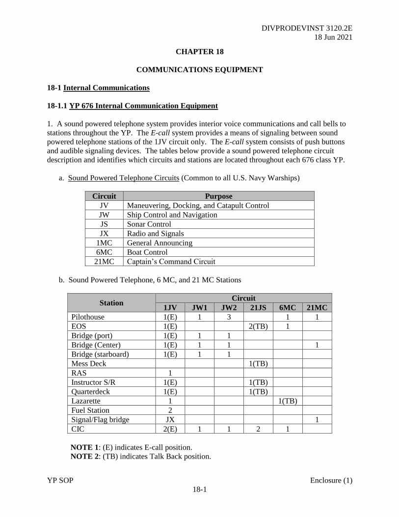
DIVPRODEVINST 3120.2E
18 Jun 2021
YP SOP Enclosure (1)
18-1
CHAPTER 18
COMMUNICATIONS EQUIPMENT
18-1 Internal Communications
18-1.1 YP 676 Internal Communication Equipment
1. A sound powered telephone system provides interior voice communications and call bells to
stations throughout the YP. The E-call system provides a means of signaling between sound
powered telephone stations of the 1JV circuit only. The E-call system consists of push buttons
and audible signaling devices. The tables below provide a sound powered telephone circuit
description and identifies which circuits and stations are located throughout each 676 class YP.
a. Sound Powered Telephone Circuits (Common to all U.S. Navy Warships)
Circuit Purpose
JV Maneuvering, Docking, and Catapult Control
JW Ship Control and Navigation
JS Sonar Control
JX Radio and Signals
1MC General Announcing
6MC Boat Control
21MC Captain’s Command Circuit
b. Sound Powered Telephone, 6 MC, and 21 MC Stations
Station Circuit
1JV JW1 JW2 21JS 6MC 21MC
Pilothouse 1(E) 1 3 1 1
EOS 1(E) 2(TB) 1
Bridge (port) 1(E) 1 1
Bridge (Center) 1(E) 1 1 1
Bridge (starboard) 1(E) 1 1
Mess Deck 1(TB)
RAS 1
Instructor S/R 1(E) 1(TB)
Quarterdeck 1(E) 1(TB)
Lazarette 1 1(TB)
Fuel Station 2
Signal/Flag bridge JX 1
CIC 2(E) 1 1 2 1
NOTE 1: (E) indicates E-call position.
NOTE 2: (TB) indicates Talk Back position.
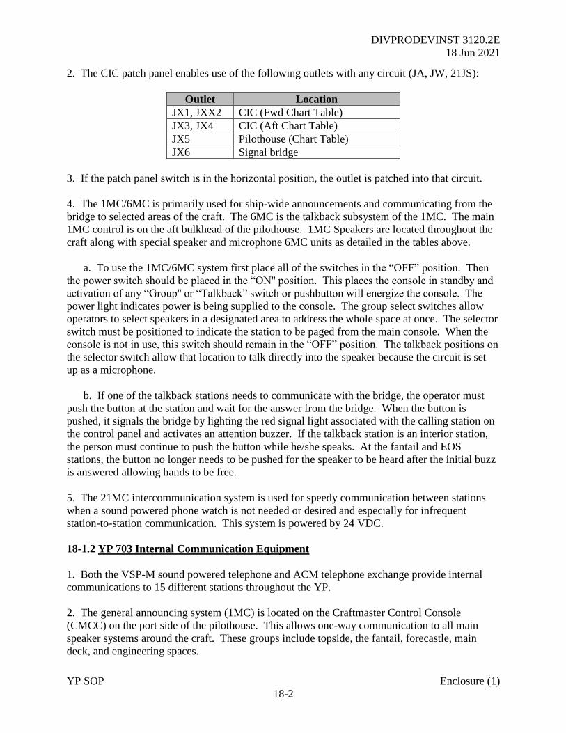
DIVPRODEVINST 3120.2E
18 Jun 2021
YP SOP Enclosure (1)
18-2
2. The CIC patch panel enables use of the following outlets with any circuit (JA, JW, 21JS):
Outlet Location
JX1, JXX2 CIC (Fwd Chart Table)
JX3, JX4 CIC (Aft Chart Table)
JX5 Pilothouse (Chart Table)
JX6 Signal bridge
3. If the patch panel switch is in the horizontal position, the outlet is patched into that circuit.
4. The 1MC/6MC is primarily used for ship-wide announcements and communicating from the
bridge to selected areas of the craft. The 6MC is the talkback subsystem of the 1MC. The main
1MC control is on the aft bulkhead of the pilothouse. 1MC Speakers are located throughout the
craft along with special speaker and microphone 6MC units as detailed in the tables above.
a. To use the 1MC/6MC system first place all of the switches in the “OFF” position. Then
the power switch should be placed in the “ON'' position. This places the console in standby and
activation of any “Group'' or “Talkback” switch or pushbutton will energize the console. The
power light indicates power is being supplied to the console. The group select switches allow
operators to select speakers in a designated area to address the whole space at once. The selector
switch must be positioned to indicate the station to be paged from the main console. When the
console is not in use, this switch should remain in the “OFF” position. The talkback positions on
the selector switch allow that location to talk directly into the speaker because the circuit is set
up as a microphone.
b. If one of the talkback stations needs to communicate with the bridge, the operator must
push the button at the station and wait for the answer from the bridge. When the button is
pushed, it signals the bridge by lighting the red signal light associated with the calling station on
the control panel and activates an attention buzzer. If the talkback station is an interior station,
the person must continue to push the button while he/she speaks. At the fantail and EOS
stations, the button no longer needs to be pushed for the speaker to be heard after the initial buzz
is answered allowing hands to be free.
5. The 21MC intercommunication system is used for speedy communication between stations
when a sound powered phone watch is not needed or desired and especially for infrequent
station-to-station communication. This system is powered by 24 VDC.
18-1.2 YP 703 Internal Communication Equipment
1. Both the VSP-M sound powered telephone and ACM telephone exchange provide internal
communications to 15 different stations throughout the YP.
2. The general announcing system (1MC) is located on the Craftmaster Control Console
(CMCC) on the port side of the pilothouse. This allows one-way communication to all main
speaker systems around the craft. These groups include topside, the fantail, forecastle, main
deck, and engineering spaces.
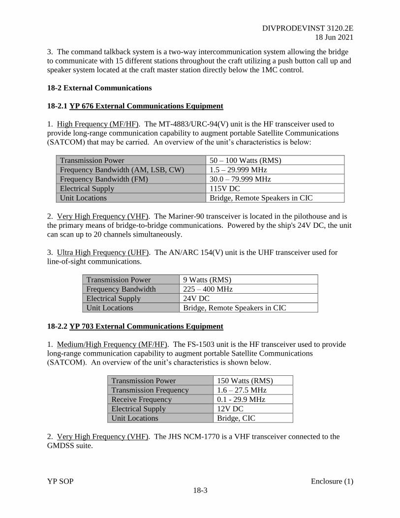
DIVPRODEVINST 3120.2E
18 Jun 2021
YP SOP Enclosure (1)
18-3
3. The command talkback system is a two-way intercommunication system allowing the bridge
to communicate with 15 different stations throughout the craft utilizing a push button call up and
speaker system located at the craft master station directly below the 1MC control.
18-2 External Communications
18-2.1 YP 676 External Communications Equipment
1. High Frequency (MF/HF). The MT-4883/URC-94(V) unit is the HF transceiver used to
provide long-range communication capability to augment portable Satellite Communications
(SATCOM) that may be carried. An overview of the unit’s characteristics is below:
Transmission Power 50 – 100 Watts (RMS)
Frequency Bandwidth (AM, LSB, CW) 1.5 – 29.999 MHz
Frequency Bandwidth (FM) 30.0 – 79.999 MHz
Electrical Supply 115V DC
Unit Locations Bridge, Remote Speakers in CIC
2. Very High Frequency (VHF). The Mariner-90 transceiver is located in the pilothouse and is
the primary means of bridge-to-bridge communications. Powered by the ship's 24V DC, the unit
can scan up to 20 channels simultaneously.
3. Ultra High Frequency (UHF). The AN/ARC 154(V) unit is the UHF transceiver used for
line-of-sight communications.
Transmission Power 9 Watts (RMS)
Frequency Bandwidth 225 – 400 MHz
Electrical Supply 24V DC
Unit Locations Bridge, Remote Speakers in CIC
18-2.2 YP 703 External Communications Equipment
1. Medium/High Frequency (MF/HF). The FS-1503 unit is the HF transceiver used to provide
long-range communication capability to augment portable Satellite Communications
(SATCOM). An overview of the unit’s characteristics is shown below.
Transmission Power 150 Watts (RMS)
Transmission Frequency 1.6 – 27.5 MHz
Receive Frequency 0.1 - 29.9 MHz
Electrical Supply 12V DC
Unit Locations Bridge, CIC
2. Very High Frequency (VHF). The JHS NCM-1770 is a VHF transceiver connected to the
GMDSS suite.
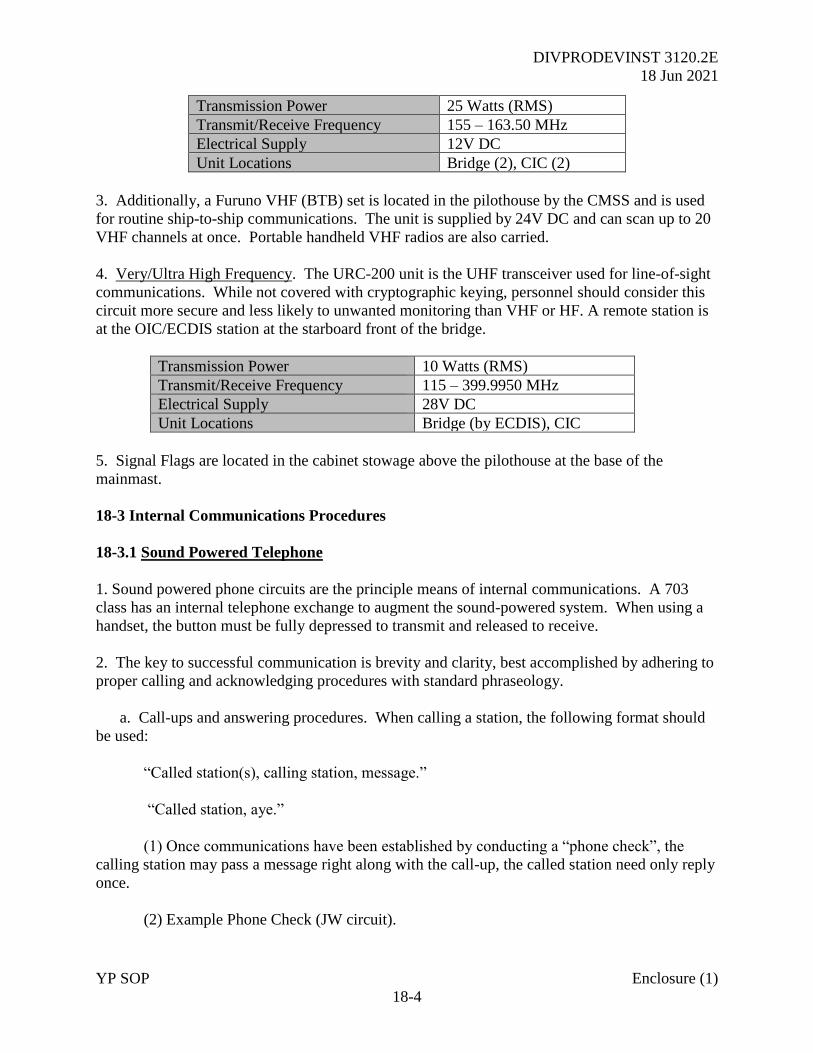
DIVPRODEVINST 3120.2E
18 Jun 2021
YP SOP Enclosure (1)
18-4
Transmission Power 25 Watts (RMS)
Transmit/Receive Frequency 155 – 163.50 MHz
Electrical Supply 12V DC
Unit Locations Bridge (2), CIC (2)
3. Additionally, a Furuno VHF (BTB) set is located in the pilothouse by the CMSS and is used
for routine ship-to-ship communications. The unit is supplied by 24V DC and can scan up to 20
VHF channels at once. Portable handheld VHF radios are also carried.
4. Very/Ultra High Frequency. The URC-200 unit is the UHF transceiver used for line-of-sight
communications. While not covered with cryptographic keying, personnel should consider this
circuit more secure and less likely to unwanted monitoring than VHF or HF. A remote station is
at the OIC/ECDIS station at the starboard front of the bridge.
Transmission Power 10 Watts (RMS)
Transmit/Receive Frequency 115 – 399.9950 MHz
Electrical Supply 28V DC
Unit Locations Bridge (by ECDIS), CIC
5. Signal Flags are located in the cabinet stowage above the pilothouse at the base of the
mainmast.
18-3 Internal Communications Procedures
18-3.1 Sound Powered Telephone
1. Sound powered phone circuits are the principle means of internal communications. A 703
class has an internal telephone exchange to augment the sound-powered system. When using a
handset, the button must be fully depressed to transmit and released to receive.
2. The key to successful communication is brevity and clarity, best accomplished by adhering to
proper calling and acknowledging procedures with standard phraseology.
a. Call-ups and answering procedures. When calling a station, the following format should
be used:
“Called station(s), calling station, message.”
“Called station, aye.”
(1) Once communications have been established by conducting a “phone check”, the
calling station may pass a message right along with the call-up, the called station need only reply
once.
(2) Example Phone Check (JW circuit).
DIVPRODEVINST 3120.2E
18 Jun 2021
YP SOP Enclosure (1)
18-5
“All stations, Navigator, comms check.”
“Port side watch station read you loud and clear.”
“Starboard watch station read you loud and clear.”
“Radar watch station read you loud and clear.”
“Fathometer watch station read you loud and clear.”
(3) Example Phone Message (1JV circuit).
“EOS, pilothouse, Indicate 1800 RPM both engines.”
“Pilot House, EOS, indicate 1800 RPM both engines, aye.”
(4) When a station joins a circuit or comes on the line, he should check in by using the
following format:
“All stations, (Calling station), on the line.”
“(Each station on circuit) Read you loud and clear.”
(5) After a long period of silence on a circuit or following any significant event, the
primary control station should conduct a phone check with all stations.
(6) When permission is given to secure a circuit or for an individual station to go off the
line, each securing station should announce:
“All stations, this is (Securing station) going offline.”
18-4 1MC (Internal Ship’s Main Broadcast). The 1MC system is the most important internal
communications circuit in the ship and is controlled by the OOD. Any message, particularly
those required by emergencies or in critical situations, should be as clear as possible. A list of
example “pipes” for use over the 1MC are listed in Appendix E.
18-5 External Communication Procedures. These communications procedures are to be used
by USNA YPs. Flaghoists and radiotelephones are the primary means of external
communication but use of other methods such as flashing light (if fitted) is encouraged.
18-5.1 Applicable Publications The following publications are to be carried onboard in
hardcopy:
a. USNA version of Multinational Maritime Tactical Signal and Maneuvering Book (MTP)
1(D), Volume 2. This document is marked UNCLASSIFIED-FOUO. The following
information is contained within this document:
(1) Detailed instructions on tactical signaling procedures.
(2) Single flag and pennant signals.
(3) Emergency alarm and emergency action signals.
DIVPRODEVINST 3120.2E
18 Jun 2021
YP SOP Enclosure (1)
18-6
(4) Maneuvering signals utilizing a special pennant (FORM, STATION, TURN,
CORPEN, and SPEED).
(5) Main signal vocabulary (two letter signals and tables) consisting of operational and
administrative signals arranged alphabetically under appropriate headings.
(6) A signal index to assist in finding the desired groups when encoding signals.
b. International Code of Signals (Pub 102). The International Code of Signals (ICS) is used
by all mariners, regardless of nationality. A naval ship precedes a signal obtained from this
publication with the ANSWER (CODE) pennant. This document includes:
(1) Detailed instructions for use.
(2) Single letter signals, usually in common use or urgent. Those marked with an asterisk
(*) can be sent by flashing light.
(3) Two-letter signals, mostly used for distress and maneuvering.
(4) Three-letter signals, used for the remaining words, phrases, and sentences.
(5) Four-letter signals, used for geographic locations.
18-6 Message Format
1. The standard naval message has three parts: heading, text, and ending. This applies to all
methods of communications except the flaghoist, which has only a heading and a text.
2. Procedures
a. A tackline, transmitted and spoken “TACK”, is used to avoid ambiguity. It separates
signals or groups of numerals that, if not separated, could convey a different meaning.
b. When ANSWER separates two numerals it is used as the decimal point. When it is the last
character it means one-half, i.e., 12 ANS 6 means “12.6” and 12 ANS means “12.5”.
c. When appropriate, DESIG followed by letters and/or numerals is used to indicate a group
that is to be interpreted literally and not as a code group. Some signals require a plain number be
used to complete the meaning of a signal. Words may be spelled out within the text of a signal
to complete or modify the meaning. Plan indicators, points, numbers, berths, etc. may also be
signaled without conflicting with signal groups.
d. Any signal preceded by EMERGENCY is to be acted upon (and hoisted closed up) as
soon as it is understood. Six short blasts are to be made on the whistle by the originator.
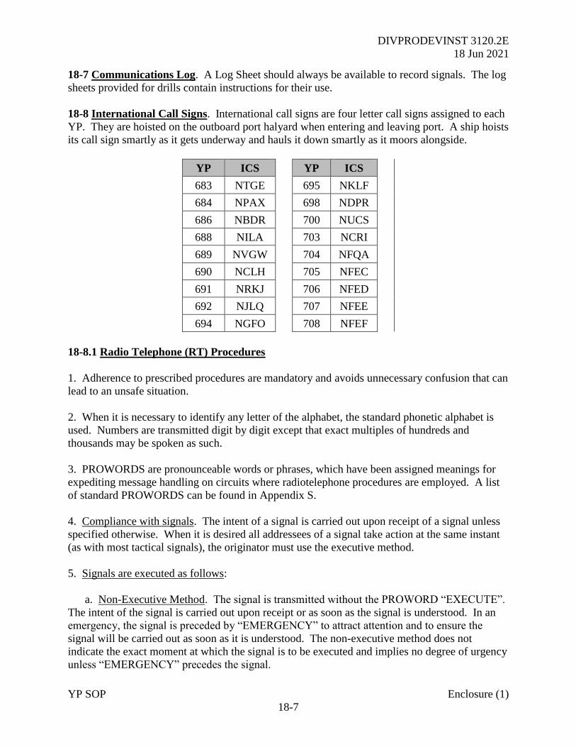
DIVPRODEVINST 3120.2E
18 Jun 2021
YP SOP Enclosure (1)
18-7
18-7 Communications Log. A Log Sheet should always be available to record signals. The log
sheets provided for drills contain instructions for their use.
18-8 International Call Signs. International call signs are four letter call signs assigned to each
YP. They are hoisted on the outboard port halyard when entering and leaving port. A ship hoists
its call sign smartly as it gets underway and hauls it down smartly as it moors alongside.
YP ICS YP ICS
683 NTGE 695 NKLF
684 NPAX 698 NDPR
686 NBDR 700 NUCS
688 NILA 703 NCRI
689 NVGW 704 NFQA
690 NCLH 705 NFEC
691 NRKJ 706 NFED
692 NJLQ 707 NFEE
694 NGFO 708 NFEF
18-8.1 Radio Telephone (RT) Procedures
1. Adherence to prescribed procedures are mandatory and avoids unnecessary confusion that can
lead to an unsafe situation.
2. When it is necessary to identify any letter of the alphabet, the standard phonetic alphabet is
used. Numbers are transmitted digit by digit except that exact multiples of hundreds and
thousands may be spoken as such.
3. PROWORDS are pronounceable words or phrases, which have been assigned meanings for
expediting message handling on circuits where radiotelephone procedures are employed. A list
of standard PROWORDS can be found in Appendix S.
4. Compliance with signals. The intent of a signal is carried out upon receipt of a signal unless
specified otherwise. When it is desired all addressees of a signal take action at the same instant
(as with most tactical signals), the originator must use the executive method.
5. Signals are executed as follows:
a. Non-Executive Method. The signal is transmitted without the PROWORD “EXECUTE”.
The intent of the signal is carried out upon receipt or as soon as the signal is understood. In an
emergency, the signal is preceded by “EMERGENCY” to attract attention and to ensure the
signal will be carried out as soon as it is understood. The non-executive method does not
indicate the exact moment at which the signal is to be executed and implies no degree of urgency
unless “EMERGENCY” precedes the signal.
DIVPRODEVINST 3120.2E
18 Jun 2021
YP SOP Enclosure (1)
18-8
b. Executive Method. The intent of the signal is carried out at the instant the PROWORD
“EXECUTE” is received.
6. Explanation of methods. The non-executive method is self-explanatory. In an emergency, it
is a sound practice to repeat the signal. There are two types of executive methods.
a. Delayed Executive. The message is sent “execute to follow” and the desired receipts are
obtained. At the time of execution, another transmission is made carrying the signal “execute”.
Repetition of the signal from the first transmission is not required in the second unless it is
included for the sake of clarity, a period of time has elapsed since the first transmission, or two
or more signals awaiting execution. All or a portion of the signal may be executed in the
originator’s second transmission. The delayed executive method is the preferred method for
transmission of tactical signals.
b. Immediate Executive. In a single transmission, the signal is spoken, repeated, and then
executed. In respect to the immediate executive method, it should be noted:
(1) It does not allow stations to obtain verifications, repetitions, acknowledgments, or
cancelations before the message is executed.
(2) Signals made by this method should be in plain language or should be limited to basic
TURN, CORPEN, and SPEED signals.
(3) “Immediate execute” is used in the place of “execute to follow” which is used in the
delayed executive method.
(4) The signal is repeated, separated by the PROWORD “I say again”.
(5) It is advisable to pause (2-4 seconds) between “STANDBY” and “EXECUTE” in
order to give any station which may have missed a portion of the signal an opportunity to request
a repeat prior to execution.
7. Communications are established and/or checked as follows:
(Called Station Call Sign), THIS IS (DE) (Calling Station Call Sign), OVER.
THIS IS (Called Station Call Sign), OVER
THIS IS (Calling Station Call Sign), ROGER, OUT.
(Communications are loud and clear unless otherwise specified)
8. Time checks are conducted as follows:
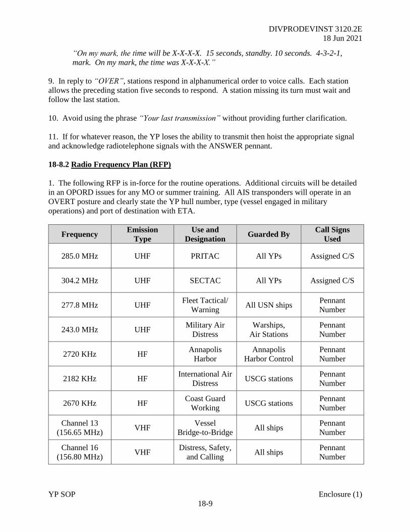
DIVPRODEVINST 3120.2E
18 Jun 2021
YP SOP Enclosure (1)
18-9
“On my mark, the time will be X-X-X-X. 15 seconds, standby. 10 seconds. 4-3-2-1,
mark. On my mark, the time was X-X-X-X.”
9. In reply to “OVER”, stations respond in alphanumerical order to voice calls. Each station
allows the preceding station five seconds to respond. A station missing its turn must wait and
follow the last station.
10. Avoid using the phrase “Your last transmission” without providing further clarification.
11. If for whatever reason, the YP loses the ability to transmit then hoist the appropriate signal
and acknowledge radiotelephone signals with the ANSWER pennant.
18-8.2 Radio Frequency Plan (RFP)
1. The following RFP is in-force for the routine operations. Additional circuits will be detailed
in an OPORD issues for any MO or summer training. All AIS transponders will operate in an
OVERT posture and clearly state the YP hull number, type (vessel engaged in military
operations) and port of destination with ETA.
Frequency Emission
Type
Use and
Designation Guarded By
Call Signs
Used
285.0 MHz UHF PRITAC All YPs Assigned C/S
304.2 MHz UHF SECTAC All YPs Assigned C/S
277.8 MHz UHF Fleet Tactical/
Warning All USN ships
Pennant
Number
243.0 MHz UHF Military Air
Distress
Warships,
Air Stations
Pennant
Number
2720 KHz HF Annapolis
Harbor
Annapolis
Harbor Control
Pennant
Number
2182 KHz HF International Air
Distress USCG stations
Pennant
Number
2670 KHz HF Coast Guard
Working USCG stations
Pennant
Number
Channel 13
(156.65 MHz) VHF
Vessel
Bridge-to-Bridge All ships
Pennant
Number
Channel 16
(156.80 MHz) VHF
Distress, Safety,
and Calling All ships
Pennant
Number
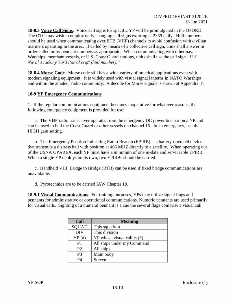
DIVPRODEVINST 3120.2E
18 Jun 2021
YP SOP Enclosure (1)
18-10
18-8.3 Voice Call Signs. Voice call signs for specific YP will be promulgated in the OPORD.
The OTC may wish to employ daily changing call signs expiring at 2359 daily. Hull numbers
should be used when communicating over BTB (VHF) channels to avoid confusion with civilian
mariners operating in the area. If called by means of a collective call sign, units shall answer in
order called or by pennant numbers as appropriate. When communicating with other naval
Warships, merchant vessels, or U.S. Coast Guard stations, units shall use the call sign “U.S.
Naval Academy Yard Patrol craft (hull number).”
18-8.4 Morse Code. Morse code still has a wide variety of practical applications even with
modern signaling equipment. It is widely used with visual signal lanterns in NATO Warships
and within the amateur radio community. A decode for Morse signals is shown at Appendix T.
18-9 YP Emergency Communications
1. If the regular communications equipment becomes inoperative for whatever reasons, the
following emergency equipment is provided for use:
a. The VHF radio transceiver operates from the emergency DC power bus bar on a YP and
can be used to hail the Coast Guard or other vessels on channel 16. In an emergency, use the
HIGH gain setting.
b. The Emergency Position Indicating Radio Beacon (EPIRB) is a battery-operated device
that transmits a distress hail with position at 406 MHZ directly to a satellite. When operating out
of the USNA OPAREA, each YP must have a minimum of one in-date and serviceable EPIRB.
When a single YP deploys on its own, two EPIRBs should be carried.
c. Handheld VHF Bridge to Bridge (BTB) can be used if fixed bridge communications are
unavailable.
d. Pyrotechnics are to be carried IAW Chapter 19.
18-9.1 Visual Communications. For training purposes, YPs may utilize signal flags and
pennants for administrative or operational communications. Numeric pennants are used primarily
for visual calls. Sighting of a numeral pennant is a cue the several flags comprise a visual call.
Call Meaning
SQUAD This squadron
DIV This division
YP (#) YP whose visual call is (#)
P1 All ships under my Command
P2 All ships
P3 Main body
P4 Screen
DIVPRODEVINST 3120.2E
18 Jun 2021
YP SOP Enclosure (1)
18-11
18-9.2 Speed Flags
1. “Speed flags” (one or two numeral flags at the dip without the SPEED pennant) are general
information signals used by individual ships to keep nearby vessels informed of the speed at
which they are proceeding while in restricted waters. “Speed signals” (speed pennant and
numeral flags) are action signals used by the OTC to signal the speed the guide is to proceed.
2. Speed flags are normally used when standing into or out of a channel, when getting underway
in formation or when in vicinity of other ships. They must be accurate if to be of any value.
3. The speed flags are displayed at the dip on an outboard signal halyard. The ZERO flag is
used when the ship is stopped, otherwise two numeral flags (one numeral flag preceded by a
ZERO flag is appropriate) are used to indicate speed at which the ship is proceeding.
18-9.3 Flaghoist Procedures Flaghoist headings:
a. The heading precedes the text and usually consists of only action addressees.
b. Visual call signs may be used for the following purposes in connection with signals from
the Allied Naval Signal Book:
(1) To address ships or other units, in which case they precede the signal.
(2) To indicate or denote ships or units, for which case they follow the signal.
(3) To complete, amplify, or vary the meaning of a signal, in which case they are used in
conjunction with the signal concerned.
c. The heading of a flag signal may be modified by use of substitute pennants as follows:
(1) SECOND SUBSTITUTE alone in the heading means “for general information; no
specific address; no answer required.”
(2) THIRD SUBSTITUTE preceding the address of a flaghoist indicates the signal, in
addition to being addressed to certain ships for action, is for general information and is to be
relayed and answered as an “all ship” signal.
d. The heading may be omitted under the following circumstances:
(1) By the OTC for signals addressed to all ships (the usual case on YP drills).
(2) By ships or commands on emergency signals addressed to the OTC.
2. The text of a flaghoist consists of such prescribed signals, operational signals (not used in
drills) and/or plain language as may be necessary to convey the meaning of the originator.
DIVPRODEVINST 3120.2E
18 Jun 2021
YP SOP Enclosure (1)
18-12
3. Hoisting flag signals
a. A flaghoist is CLOSE-UP when its top is touching the block at the point of hoist. The
originator hoists a signal close-up.
b. A flaghoist is AT THE DIP or DIPPED when hoisted three-fourths of the way up towards
the point of the hoist. Hoists are dipped until “understood” by the OOD and properly
acknowledged.
c. A flaghoist is HAULED DOWN when it is returned to the signal deck. The moment of
hauling down is the moment of execution unless the time of execution is indicated or the
emergency pennant is used.
d. Ships repeating the OTC’s signals do so with halyards corresponding to those of the OTC.
Flags must be kept clear. If there is not enough wind to blow the flags out so they can be read
easily, the hoists should be kept on the move.
e. Any two signals using SPEED, STATION, CORPEN, FORMATION, or TURN pennants
should be displayed on separate halyards so they can be individually executed.
4. The order of reading flag signals is as follows
a. Signal flags of a single hoist are read from top to bottom.
b. Adjacent hoists are read down, from outboard to inboard and from forward to aft.
5. Answering and acknowledging flag signals
a. Flaghoists are answered by addressees repeating the entire hoist at the dip. Lacking any
of the flags of the hoist, it is answered by use of the ANSWER pennant alone.
b. A senior officer may answer a subordinate’s flaghoist by hoisting ANSWER at the dip,
either alone or below the originator’s call.
c. Acknowledgment is affected by hoisting the signal (or ANSWER, if appropriate) closed-
up. Signals are hoisted closed-up when understood by the OOD and by repeating stations when
all addressees for whom they are responsible have acknowledged.
5. When an addressee cannot determine the meaning of a hoist or desires to question the
meaning, the signal (or ANSWER, if appropriate) is hoisted at the dip and the
INTERROGATIVE pennant hoisted close-up on an adjacent halyard.
6. Executing Flag Signals
DIVPRODEVINST 3120.2E
18 Jun 2021
YP SOP Enclosure (1)
18-13
a. Unless otherwise indicated a flag signal is executed when the originator hauls down the
hoist.
b. Certain signals are executed at some time other than when the originator hauls them
down, as indicated in the meaning of the signal.
c. All addressees haul down with the originator.
d. The first execute received will govern the time of execution when a signal is executed by
more than one means (e.g., radiotelephone and flaghoist).
7. Canceling Flag Signals
a. Flaghoist signals are canceled by the following use of the NEGATIVE pennant:
(1) When only one flag signal is flying, NEGATIVE hoisted on an adjacent halyard
cancels the signal.
(2) When two or more flag signals are flying under the same call, NEGATIVE hoisted on
an adjacent halyard cancels all signals flying. If only one signal is to be canceled, it must be
repeated, preceded by NEGATIVE.
b. Visual responsibility is exercised with the NEGATIVE pennant. Only NEGATIVE is
closed-up. The signal being cancelled remains at the dip until hauled down (which is done from
the dip position).
c. A flaghoist signal may be corrected as follows:
(1) The originating ship cancels the signal, and then hoists the correct signal.
(2) Any repeating ship hoists the signal meaning “signal is repeated incorrectly” on an
adjacent halyard, then hauls down both signals. The correct signal is then hoisted.
8. Substitute pennants are not used with international calls or with high-speed flags.
9. Procedures applicable to YPs only
a. Numeral flags and pennants may be interchanged when necessary.
b. The ANSWER pennant is used to indicate receipt of radio telephone signals in case of a
transmitter casualty.
c. The outboard halyard should not be used. This assures a superior position being available
should one be desired.

DIVPRODEVINST 3120.2E
18 Jun 2021
YP SOP Enclosure (1)
18-14
d. The numeral pennants displayed by the YPs are visual calls rather than digits of a ship’s
hull number as is the practice in the Fleet. Generally, YP visual call sign numbers are the same
as sequence numbers.
18-10 International Code of Signals. An extract of common signals is included for reference at
Appendix T.
DIVPRODEVINST 3120.2E
18 Jun 2021
YP SOP Enclosure (1)
19-1
CHAPTER 19
SOLAS PYROTECHNICS
19-1 General Instructions.
1. USCG and the Department of Homeland Security mandate carriage of Visual Distress Signals
to an extent defined by the classification of vessels. YPs align to commercial passenger vessels
and are therefore required to carry one ORION Flare Pack. However, in agreement with the
USCG, USNA YPs will only be required to carry SOLAS Flares when deployed outside the
Local Operations Area.
2. Flare packs are to include the following items:
Quantity Item
6 12 Gauge Red Aerial Signals
1 Launcher (with bandolier)
5 Red Handheld Signals
1 Orange Handheld Smoke Signal
1 Volare Floating Storage Bag
19-2 Pre-Planned Use for Training. Throughout the summer period, several flares will be
expended in support of underway training serials. Prior to any demonstration serial, permission
is to be sought from PRODEV for the in-area planned operation of any signal flare. A Local
Notice to Mariners (LNTM) is to be issued, alongside warning calls over VHF Channels 16 and
12. The Annapolis Coast Guard Station is also to be informed.
19-3 Accountability of Pyrotechnics. When deployed, the OIC is to keep account of all pyro
consumables ensuring they are properly secured. Alongside, the flare pack is to be kept under
the supervision of the Duty OIC/CM and at sea in the pilothouse ready for use under control of
the OOD.
19-4 Operation
1. In any emergency, the OIC or CM will direct the use of the appropriate flare signal or
smoke. A radio message should be passed via VHF/PRITAC to all ships in company prior to
operating any flare. When in close company, only one signal should be used at a time to
preserve the pyro stockpile and only after sighting a potential rescue vessel or aircraft.
2. Flare Gun. Break open the launcher barrel and insert (only) one ORION 12-Gauge HP aerial
flare. Close launcher. If the barrel does not fully close, do not force it. Remove the signal flare
and insert another, ensuring the barrel is free of any debris or other obstructions. Point the flare
gun in a safe direction and discharge the flare.
DIVPRODEVINST 3120.2E
18 Jun 2021
YP SOP Enclosure (1)
19-2
3. Hand-held Red Signal Flares and Orange Smoke Signals. Remove the black lid on the red
cap. Twist the red cap clockwise and remove. Firmly grasp the bottom of the flare holding
below the line clearly marked on the label. Point away from face and body, ensuring it is held
downwind. Light the flare by running the red plastic cap across the black button with pressure
down and away from the user’s body. Do not waive the signal over your head. Hold it over the
side of the craft in the downwind direction.
19-5 Long Term Storage All ORION Flare Packs are to be held at the Armory. The Senior
CM is to arrange the collection and return of flare packs as required for deployed Operations,
ensuring each craft planning to get underway holds 1 flare pack.
DIVPRODEVINST 3120.2E
18 Jun 2021
YP SOP Enclosure (1)
20-1
CHAPTER 20
DECK EQUIPMENT
20-1 Shipboard Responsibility. The CM is responsible for all deck evolutions including
anchoring, line handling, towing, and fender details. A qualified safety observer (AOIC or CM)
will be on deck for all such evolutions while the OIC is in overall command. The bridge is
always to be informed if the status of any deck equipment changes.
20-2 Deck Equipment
20-2.1 Ground Tackle
1. A summary of equipment installed on the 676 class is shown below:
a. 676 class YPs have USN lightweight Danforth anchors weighing 300 pounds each that are
housed in their respective port and starboard hawsepipes on the foc’sle.
b. Each anchor is provided with 70 fathoms (420 feet) of one half inch chain. The chain is
marked in 15-foot shots with fleet standard markings. These markings are painted on the
detachable links of the anchor chain in the following repeating order: red (R), white (W), and
then blue (B). The entire “next to last” shot (15 feet) of chain is painted yellow while the entire
last shot of chain is painted red.
c. The anchor windlass (Model X-1866) is motor driven and reversible in direction. Its
function is to raise, lower, and stow the anchor and chain. By using the gypsy head, the windlass
can also be used to assist with handling heavy mooring lines. The windlass has five major
components: the wildcat, gypsy head, brake, motor, and pushbutton station.
(1) The Wildcat is sized for one-half inch stud-linked chain and can pull the anchor and
70 fathoms of chain (approximately 3,400 pounds) at a rate of 34 feet per minute.
(2) Two Gypsy Heads are located on the outboard sides of the windlass and are used for
line handling. Each head is nine inches in diameter and electrically controlled from the
pushbutton station. The motor can pull a maximum weight of 2,700 pounds at a rate of 44 feet
per second. To operate, wrap the line to be handled around the head two or three times. Be sure
lines are not crossed or tangled around the head before proceeding. Make sure the clutch handle
is disengaged from the motor shaft and pinned to the inboard position by the clutch lock pin.
This allows the motor shaft and gypsy head to rotate without the wildcat. Push the “hoist” or
“lower” button, depending on the desired direction of heaving. To keep the line from slipping
around the gypsy head, tension must be put on the line by applying hand-tended strain to the part
of the line where the motion is away from the gypsy head.
(3) The Brake is a mechanically operated disc-type brake with a rating of 15 foot-
pounds. Brake tension is regulated by turning the brake wheel to allow for the desired shaft
rotation.
DIVPRODEVINST 3120.2E
18 Jun 2021
YP SOP Enclosure (1)
20-2
(4) The Motor, which is located on the main deck, is a 440 volt, 60 Hz, 3-phase unit.
The rating for this motor is 5 HP. The motor is operated at one speed only but in two directions.
Its direction is controlled from the pushbutton station.
(5) The Pushbutton Station is located in the center of the rear side of the windlass.
There are two buttons (hoist and lower) which control the direction of rotation. These switches
are known as “deadman’s switches”, meaning the switch must be continuously pressed to operate
or the shaft will stop rotating as soon as released.
2. A summary of the equipment installed in a 703 class is shown below:
a. 703 class YPs have two 350-pound HP Talon balanced fluke anchors that are housed in
separate hawsepipes on the Foc’sle.
b. The anchors are attached to a three-quarter inch chain. The port chain has three 15-
fathom shots (270 feet) and the starboard is made up of seven 15-fathom shots (630 feet). Shots
are painted in 15-fathom sections with standard markings.
c. The Windlass is a Coastal Marine Equipment Inc. (Model 2W07531-136-00). By using
the gypsy head, the windlass can assist handling heavy mooring lines and has five major
components; the Wildcat, Gypsy Head, Brake, Motor, and Pushbutton Station.
(1) The Wildcat is sized for a three quarter inch chain and can pull the 350-pound anchor
and 630 feet of chain at approximately 33 feet per minute.
(2) There are two 10-inch diameter Gypsy Heads located outboard each side of the
windlass with a maximum pulling weight of 3,590 pounds.
(3) The Brake is a mechanically operated disc-type with a rating of 30,600 pounds.
(4) The Windlass motor is rated at 7.5 HP with a 480V, 60 Hz, 3 Phase electrical supply.
The Push Button controller located on the port side aft of the windlass.
(5) Four chain stoppers (two for each anchor chain) are installed forward of the anchor
windlass.
20-2.2 Deck Gear
1. The following deck equipment is carried on YPs:
Equipment Quantity
Heaving Lines 4
Grapple Hook 1
Jacob’s Ladder 1
Boat Hook (6 & 12 foot long) 2 (1 of each)
DIVPRODEVINST 3120.2E
18 Jun 2021
YP SOP Enclosure (1)
20-3
MOB Recovery Line with Bowline
loop immediately available.
1
2. Mooring & Towing Fittings
a. The 676 class YP has six sets of bitts and eight chocks installed on the main deck, port,
and starboard sides. One bullnose chock is installed on each side of the bow and three stern
chocks are installed aft. A towing bitt is also installed on the fantail.
b. The 703 class YP has eight sets of bitts and eight chocks installed on the main deck, port,
and starboard sides. There is one bullnose chock on the bow and three stern chocks aft. There is
a towing bitt on the forward side of the Foc’sle and one aft on the fantail.
c. Six 3-inch double braided nylon mooring lines are carried on each YP. One 3.5-inch
plaited towing hawser 300 feet long. 676 Class are also to carry two 3.5-inch plaited towing
bridles 50 feet long. These are not required on the 703 Class due to the forward towing bitt.
Lines are of a predetermined length and should not be cut except in an emergency. Two portable
pneumatic fenders are carried on board each 703 class.
d. On the deck the following equipment is to be available:
YP’s Fire Axe to cut hawser in emergency Pliers
Boat Hook 2 x Radios
Sail Twin Knife
Heaving Lines
20-2.3 Lifesaving Equipment
1. Each YP is to carry a navy issue First Aid Kit, Small (NSN 654500168693) as a minimum.
Navy Corpsman will bring further equipment on board when embarked for OOA operations.
2. Sterns inherently buoyant type life jackets (33 on 676 and 42 on 703) are stowed in 01 Deck
life jacket lockers.
3. Two 24 inch life rings with strobe-type marker lights are located on the main deck amidships,
one on each side. An additional two life rings are located on the 01 level.
4. Two 25-person Mark 7 (676 class) or four 25-person Mark 7 (703 class), self-contained life
rafts are provided on port and starboard sides and are equipped with a manual and automatic
hydrostatic release. The hydrostatic release is triggered at an approximate depth of 10 feet so not
to inadvertently release in heavy weather. The device is stowed with the can opening facing aft.
DIVPRODEVINST 3120.2E
18 Jun 2021
YP SOP Enclosure (1)
20-4
5. To initiate manual release, remove the cotter key to allow separation. A secondary method is
to cut the 5 lashings attaching the release device to the life raft slings. 703 Class use commercial
release devices that can be manually released by pulling the red pull ring. The life raft is inflated
by pulling the sea painter (length-100ft) which extends through an opening in the container. This
step should only be accomplished after the container has been launched. The end of the sea
painter should be tied securely to the stowage rack. The painter’s predetermined breaking
strength is less than the buoyancy of the craft and will break free once the compressed air
inflation system has operated.
6. Each life raft is fitted with the following safety equipment:
Floatable knife Boarding light Paddles Sea Anchor
2 x Hand Pumps Bailer Flashlight Signal Mirror
First Aid Kit Signal Whistle Fishing Tackle Radar Reflector
Sea Marker Five desalter kits 50 sealed cans of drinking water
DIVPRODEVINST 3120.2E
18 Jun 2021
YP SOP Enclosure (1)
21-1
CHAPTER 21
DAMAGE CONTROL EQUIPMENT REQUIREMENTS
21-1 676 Class Damage Control
1. The 676 is a wooden vessel making it imperative any casualty, especially fire, be dealt with
quickly and effectively. A thorough knowledge of how to use all DC equipment is essential.
2. The frame spacing on a 676 class YP is 18 inches.
3. Compartment check-off lists (CCOL) are provided for all spaces.
4. Compartment bullseyes reflective blue lettering on a photoluminescent back are posted in
each space showing compartment numbers, noun names of the compartment, the forward and
after frames in the space, and the division responsible for cleaning the space.
21-2 676 Class Damage Control Equipment
1. Damage control equipment is stowed in the large canvas bag and bins of the 676 class YPs
DC locker. Damage control equipment on YPs will consist of the following:
DC EQUIPMENT QUANTITY
FIRE AXE 1
CLAW HAMMER 2
HAND SAW 2
HATCHET 1
RUBBER SHEET 1 ROLL
MARLIN 200’ 1
OAKUM 5 LBS
DC PLUGS (SMALL) 4
DC PLUGS (MEDIUM) 4
DC PLUGS (LARGE) 4
DC WEDGE (SMALL) 4
DC WEDGE (MEDIUM) 4
DC WEDGE (LARGE) 4
HACK SAW 2 WITH 10 ADDITIONAL BLADES
2 ½” HOSE (50’) 2
1 ½” HOSE (50’) 2
SPANNER WRENCH 2
MAULS 2
PORTABLE BATTLE LANTERN 3
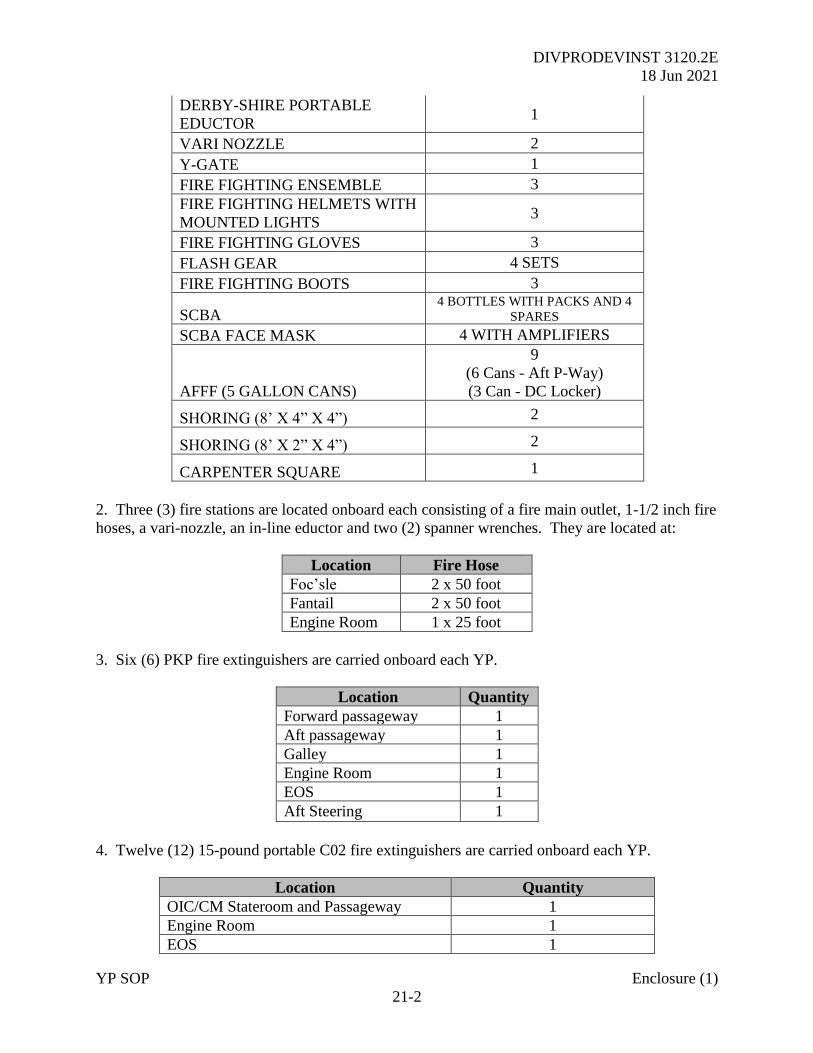
DIVPRODEVINST 3120.2E
18 Jun 2021
YP SOP Enclosure (1)
21-2
DERBY-SHIRE PORTABLE
EDUCTOR 1
VARI NOZZLE 2
Y-GATE 1
FIRE FIGHTING ENSEMBLE 3
FIRE FIGHTING HELMETS WITH
MOUNTED LIGHTS 3
FIRE FIGHTING GLOVES 3
FLASH GEAR 4 SETS
FIRE FIGHTING BOOTS 3
SCBA 4 BOTTLES WITH PACKS AND 4
SPARES
SCBA FACE MASK 4 WITH AMPLIFIERS
AFFF (5 GALLON CANS)
9
(6 Cans - Aft P-Way)
(3 Can - DC Locker)
SHORING (8’ X 4” X 4”) 2
SHORING (8’ X 2” X 4”) 2
CARPENTER SQUARE 1
2. Three (3) fire stations are located onboard each consisting of a fire main outlet, 1-1/2 inch fire
hoses, a vari-nozzle, an in-line eductor and two (2) spanner wrenches. They are located at:
Location Fire Hose
Foc’sle 2 x 50 foot
Fantail 2 x 50 foot
Engine Room 1 x 25 foot
3. Six (6) PKP fire extinguishers are carried onboard each YP.
Location Quantity
Forward passageway 1
Aft passageway 1
Galley 1
Engine Room 1
EOS 1
Aft Steering 1
4. Twelve (12) 15-pound portable C02 fire extinguishers are carried onboard each YP.
Location Quantity
OIC/CM Stateroom and Passageway 1
Engine Room 1
EOS 1
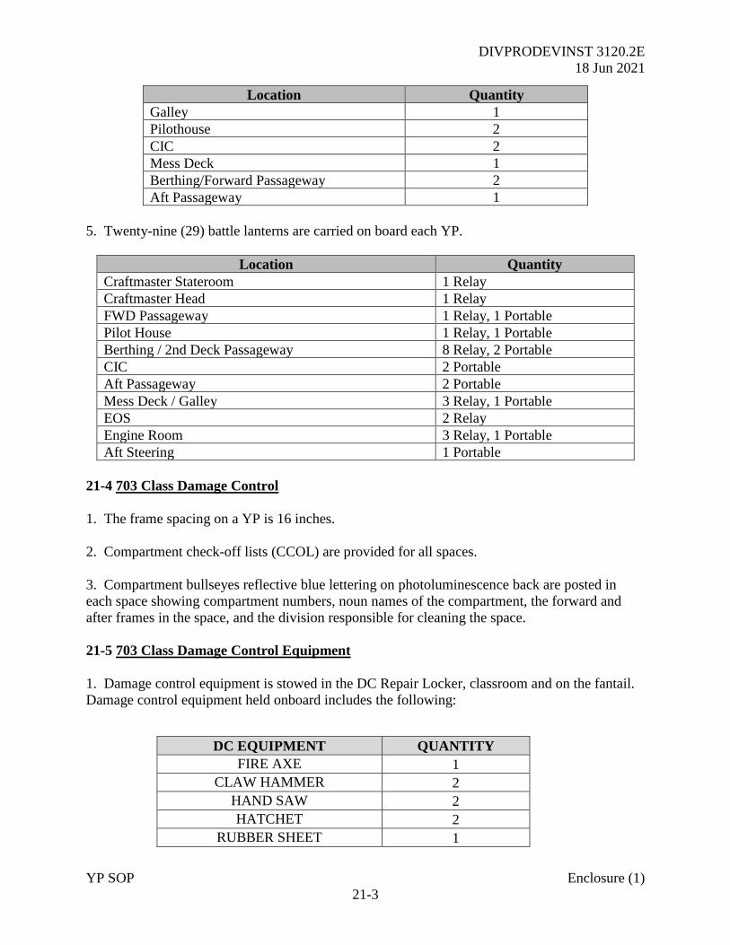
DIVPRODEVINST 3120.2E
18 Jun 2021
YP SOP Enclosure (1)
21-3
Location Quantity
Galley 1
Pilothouse 2
CIC 2
Mess Deck 1
Berthing/Forward Passageway 2
Aft Passageway 1
5. Twenty-nine (29) battle lanterns are carried on board each YP.
Location Quantity
Craftmaster Stateroom 1 Relay
Craftmaster Head 1 Relay
FWD Passageway 1 Relay, 1 Portable
Pilot House 1 Relay, 1 Portable
Berthing / 2nd Deck Passageway 8 Relay, 2 Portable
CIC 2 Portable
Aft Passageway 2 Portable
Mess Deck / Galley 3 Relay, 1 Portable
EOS 2 Relay
Engine Room 3 Relay, 1 Portable
Aft Steering 1 Portable
21-4 703 Class Damage Control
1. The frame spacing on a YP is 16 inches.
2. Compartment check-off lists (CCOL) are provided for all spaces.
3. Compartment bullseyes reflective blue lettering on photoluminescence back are posted in
each space showing compartment numbers, noun names of the compartment, the forward and
after frames in the space, and the division responsible for cleaning the space.
21-5 703 Class Damage Control Equipment
1. Damage control equipment is stowed in the DC Repair Locker, classroom and on the fantail.
Damage control equipment held onboard includes the following:
DC EQUIPMENT QUANTITY
FIRE AXE 1
CLAW HAMMER 2
HAND SAW 2
HATCHET 2
RUBBER SHEET 1
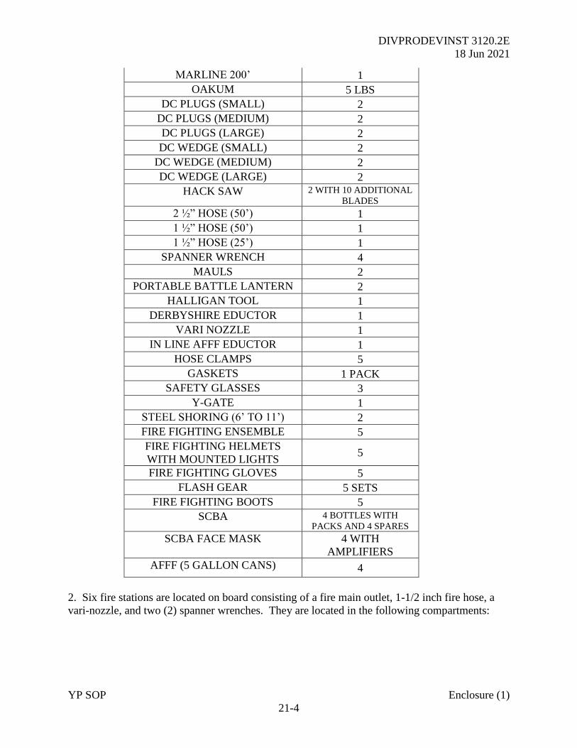
DIVPRODEVINST 3120.2E
18 Jun 2021
YP SOP Enclosure (1)
21-4
MARLINE 200’ 1
OAKUM 5 LBS
DC PLUGS (SMALL) 2
DC PLUGS (MEDIUM) 2
DC PLUGS (LARGE) 2
DC WEDGE (SMALL) 2
DC WEDGE (MEDIUM) 2
DC WEDGE (LARGE) 2
HACK SAW 2 WITH 10 ADDITIONAL
BLADES
2 ½” HOSE (50’) 1
1 ½” HOSE (50’) 1
1 ½” HOSE (25’) 1
SPANNER WRENCH 4
MAULS 2
PORTABLE BATTLE LANTERN 2
HALLIGAN TOOL 1
DERBYSHIRE EDUCTOR 1
VARI NOZZLE 1
IN LINE AFFF EDUCTOR 1
HOSE CLAMPS 5
GASKETS 1 PACK
SAFETY GLASSES 3
Y-GATE 1
STEEL SHORING (6’ TO 11’) 2
FIRE FIGHTING ENSEMBLE 5
FIRE FIGHTING HELMETS
WITH MOUNTED LIGHTS 5
FIRE FIGHTING GLOVES 5
FLASH GEAR 5 SETS
FIRE FIGHTING BOOTS 5
SCBA 4 BOTTLES WITH
PACKS AND 4 SPARES
SCBA FACE MASK 4 WITH
AMPLIFIERS
AFFF (5 GALLON CANS) 4
2. Six fire stations are located on board consisting of a fire main outlet, 1-1/2 inch fire hose, a
vari-nozzle, and two (2) spanner wrenches. They are located in the following compartments:
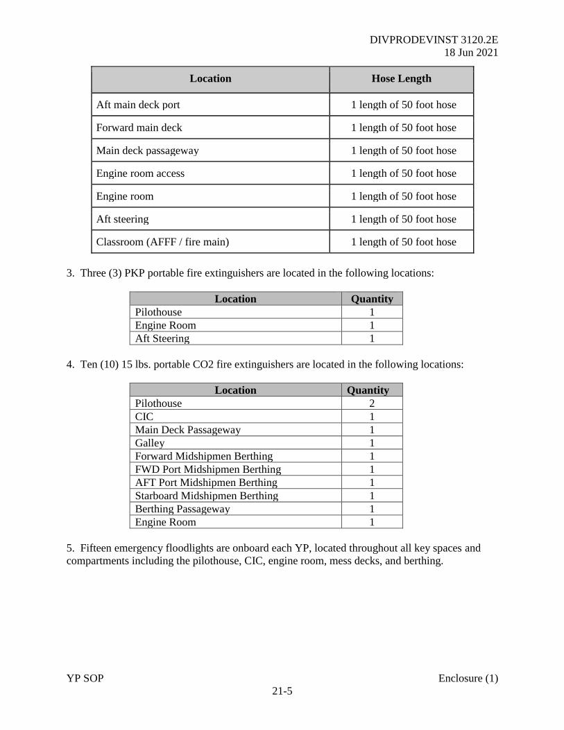
DIVPRODEVINST 3120.2E
18 Jun 2021
YP SOP Enclosure (1)
21-5
Location Hose Length
Aft main deck port 1 length of 50 foot hose
Forward main deck 1 length of 50 foot hose
Main deck passageway 1 length of 50 foot hose
Engine room access 1 length of 50 foot hose
Engine room 1 length of 50 foot hose
Aft steering 1 length of 50 foot hose
Classroom (AFFF / fire main) 1 length of 50 foot hose
3. Three (3) PKP portable fire extinguishers are located in the following locations:
Location Quantity
Pilothouse 1
Engine Room 1
Aft Steering 1
4. Ten (10) 15 lbs. portable CO2 fire extinguishers are located in the following locations:
Location Quantity
Pilothouse 2
CIC 1
Main Deck Passageway 1
Galley 1
Forward Midshipmen Berthing 1
FWD Port Midshipmen Berthing 1
AFT Port Midshipmen Berthing 1
Starboard Midshipmen Berthing 1
Berthing Passageway 1
Engine Room 1
5. Fifteen emergency floodlights are onboard each YP, located throughout all key spaces and
compartments including the pilothouse, CIC, engine room, mess decks, and berthing.
DIVPRODEVINST 3120.2E
18 Jun 2021
YP SOP Enclosure (1)
SECTION 5
SEAMANSHIP FITTINGS AND YP EVOLUTIONS
DIVPRODEVINST 3120.2E
18 Jun 2021
YP SOP Enclosure (1)
22-1
CHAPTER 22
SEAMANSHIP - ANCHORING AND TOWING
22-1 Anchoring
22-1.1 Planning
1. Always fully consider the navigation plan, prevailing and forecasted conditions, including but
not limited to:
a. Last time anchor windlass was employed successfully, condition of the chain, and
visibility of markings.
b. Approach to anchorage - What are the prevailing conditions - wind or tidal stream?
c. Aids to Navigation – are sufficient conspicuous marks available for visual and radar
pilotage? Do not rely on VMS/ECDIS alone.
d. Proximity to shoal water, obstructions, traffic routes or any other hazards.
e. Bottom Characteristics – is it good holding ground?
f. Depth of water – deep or shallow water anchorage? How many shots required?
g. Shelter from prevailing seas and weather.
2. On a 676 class YP, one “shot” is 15 feet while on a 703 class YP one “shot” is 90 feet.
22-1.2 Procedures
1. It is important that all appropriate safety precautions be taken when conducting any
seamanship evolution. When anchoring, all personnel directly involved with the evolution must
wear the essential protective equipment.
2. Prior to anchoring the OIC and CM will determine a suitable location and approach track.
Seamanship Fundamentals for the Deck Officer (Chapter 6) and Dutton’s (Chapter 14) provide
further reference material.
3. The Anchoring Evolution Checklists are in Appendix Q.
4. The following steps are to be followed for anchoring in shallow water:
a. Complete an operational test of anchor windlass.
DIVPRODEVINST 3120.2E
18 Jun 2021
YP SOP Enclosure (1)
22-2
b. Verify the brake is set and engage the wildcat. (CAUTION: DO NOT STRADDLE
OR STEP OVER THE ANCHOR CHAIN AT ANY TIME). Remove the riding stopper.
c. Disengage the wildcat. The clutch shifter should be in the inboard position and the lock
pin should be secured in the handle.
d. Notify the bridge that the anchor is ready for letting go.
e. When the command “stand by the port/starboard anchor” is received, verify the brake is
set and release the housing stopper.
f. When the command “let go the port/starboard anchor” is given, the brake is released
and the anchor will pay out under its own weight.
g. When the anchor is let go, colors are shifted and the appropriate day shape or light is
displayed.
h. Veer out the chain in accordance as directed from the bridge. Once enough chain is out,
set the brake by turning the brake wheel fully clockwise so that the anchor can be set.
i. Once the anchor is set, release the brake and veer out the chain to the directed scope.
j. Set the brake, pass the housing and riding stoppers, and engage the wildcat.
k. Set the anchor watch as directed by the OIC/CM.
5. When anchoring it deep water use the windlass to mechanically lower the anchor rather than
allowing the anchor to free fall to the bottom. The following steps are to be followed for
anchoring in deep water (48 feet or greater for a YP):
a. Engage the wildcat by moving the clutch shifter to the outboard position and then set the
lock pin back in place.
b. Jog the motor by pushing the lower button momentarily. This will allow the teeth of the
wildcat to mesh with the teeth of the motor shaft.
c. Remove both the housing and riding chain stoppers.
d. Release the brake fully by slowly turning the brake wheel counter-clockwise.
e. Push the “lower” button on the pushbutton station. This will mechanically lower the
anchor at a constant speed.
f. When the anchor is within 20 to 25 feet of the bottom, push the “stop” button.
DIVPRODEVINST 3120.2E
18 Jun 2021
YP SOP Enclosure (1)
22-3
g. Set the brake. After this is done, disengage the wildcat following the same procedures as
stated for shallow anchoring. (CAUTION: Do not disengage or engage the wildcat before the
motor is stopped and the brake and stop are set).
h. Thereafter, allow the anchor to free fall to the bottom following the procedures listed
above for Shallow Water Anchoring.
6. When Weighing Anchor the steps listed below are to be followed:
a. Engage the wildcat by putting the clutch shifter in the outboard position and replacing the
lock pin into its hole.
b. Jog the motor by pushing momentarily the hoist button for the motor shaft teeth to mesh
with the wildcat teeth.
c. Release the riding and housing stoppers from the anchor chain.
d. Release the brake by turning the brake wheel counter-clockwise (The wildcat will turn
slightly until the teeth engage).
e. Push the “hoist” button.
f. Using the 1.5-inch fire hose, direct a stream of water onto the chain as it comes up
through the hawse pipe.
g. House the anchor in the hawse pipe. The anchor is housed when the shank of the anchor
is inside the hawse pipe and the anchor chain is taut, but not under heavy strain.
h. After the anchor is housed in the hawse pipe, pass the chain stops back into the chain and
set the brake as previously described.
7. When anchoring, the following communications should be made between the bridge and
forecastle.
a. By the bridge: Depth of the water, type of bottom, scope of chain, and range to
anchorage.
b. By the Foc’sle: The anchor conditions (holding or dragging, how the anchor is tending –
“9 o’clock”, “12 o’clock”, and tension of anchor chain - light, heavy).
8. When weighing anchor, the following communications are to be made:
a. The number of shots of chain that have reached the deck, whether the anchor is at short
stay, up and down, or aweigh and whether it is clear, foul, or shod.
DIVPRODEVINST 3120.2E
18 Jun 2021
YP SOP Enclosure (1)
22-4
22-2 Towing Procedures
1. The towing equipment described at Chapter 20 is to be immediately available on the deck.
The two methods by which a YP may tow or be towed by another are the alongside or astern
methods.
2. Alongside. Often referred to as “towing by the hip” or “hip tow”, this method offers the
greatest level of control. It is ideal for towing in channels or congested waterways. The towing
vessel will make an approach alongside the vessel to be towed and use a four-line configuration
to secure the casualty craft. This consists of a bowline, stern line, forward, and after spring lines.
Three-inch double braided mooring lines can be utilized to rig this configuration. Fenders shall
be rigged between the two vessels to prevent damage during the towing evolution.
3. Astern. Best used in open water, this configuration is less likely to result in any physical
damage caused by movement of craft while secured. Each YP is equipped with a 300-foot long
towing hawser of 3 1/2 inch plaited nylon line for use when towing astern and two 50-foot long 3
1/2 inch plaited lines which are to be used as bridles when being towed. The end of the towing
hawser with the hard eye (thimble) must be passed from the towing vessel to the disabled vessel
by use of a heaving line and messenger. Once passed, there are two means by which it may be
secured to the towed vessel depending on whether the towing duration will be long or short.
a. Short Duration Tow. Expected duration of less than five hours. The soft eye of the
towing hawser is placed over the towing bitt on the towing vessel. The hard eye is passed to the
towed vessel and attached to the bridle by a 1 1/2 inch safety shackle.
b. Long Duration Tow. When expected duration is greater than five hours, the towed
vessel will shackle its towing hawser into the bridle and will shackle the soft eye with the hard
eye of the towing ship’s hawser. The towing ship will rig the towing hawser the same as for a
short duration tow. This doubles the length of the tow providing a safe distance for a longer
duration tow.
2. Caution. When a strain is taken on the towline, there will be no catenary and the entire rig
will ride out of the water at about the level of the foc’sle. This situation is potentially very
hazardous due to the increased chance of parting the rig. If the rig parts are under heavy strain,
the pendant will recoil onto and sweep the foc’sle of the towed vessel. Extreme care must be
taken when towing with this rig and safety must not be compromised for speed.
Consideration may need to be given to facilitating an adjustment to the length of the tow.
3. Further reference material is available in the publication Naval Shiphandling, Chapter 9.

DIVPRODEVINST 3120.2E
18 Jun 2021
YP SOP Enclosure (1)
23-1
CHAPTER 23
OPERATING WITH ROTARY WING AIRCRAFT
23-1 General Overview. Naval warships routinely operate with rotary wing (RW) aircraft in a
wide range of challenging missions from VERTREP to ASW action. YPs are not able to embark
aircraft of any type although there is training value in practicing ship-Aircraft communications
drills, general preparations for flying operations and MEDEVAC winching drills.
2. Planned exercises between aircraft and YPs will be carefully planned and briefed in advance.
Medical evacuations may take place at short notice in extremis. SEANAV approval should be
sought if the situation permits.
23-2 Scheduling. YP training will generally be conducted in liaison with local USCG. For
training underway, USCG H-65 Dauphin Operations are currently scheduled from Atlantic City,
NJ and can be reached by telephone at (609) 677-2110.
2. Alternatively, with permission from USNA Air Ops, aircraft may be scheduled to land and
shutdown to provide static displays and in-person briefing before training underway.
23-3 Pre-Exercise Briefing
1. Out of Area, the OTC is responsible for coordinating a comprehensive briefing for
participating personnel prior to commencing any exercise with a live aircraft. If training within
the local USNA area. This is to be coordinated between SEANAV Ops and WFR Ops. The
briefing will consider all aspects of ship and aircraft safety including (but not limited to):
a. Weather Forecast.
b. SOE and geographical limits of the planned exercise OPAREA.
c. COMPLAN with frequencies and call signs.
d. Preparations for Flying including RADHAZ and FOD Walkdown.
e. Shoal water and all hazards to marine navigation including expected traffic density.
f. Planned Flying Courses.
g. Command Aim for the Exercise.
h. SOA required for Next Serial.
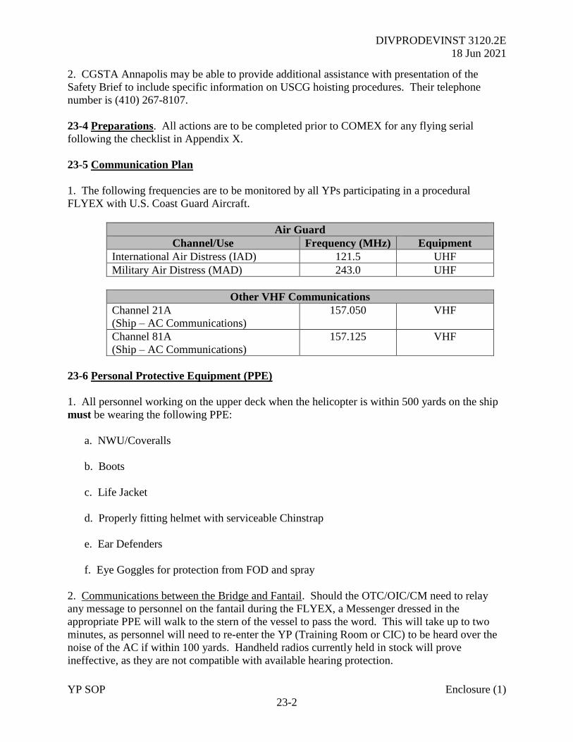
DIVPRODEVINST 3120.2E
18 Jun 2021
YP SOP Enclosure (1)
23-2
2. CGSTA Annapolis may be able to provide additional assistance with presentation of the
Safety Brief to include specific information on USCG hoisting procedures. Their telephone
number is (410) 267-8107.
23-4 Preparations. All actions are to be completed prior to COMEX for any flying serial
following the checklist in Appendix X.
23-5 Communication Plan
1. The following frequencies are to be monitored by all YPs participating in a procedural
FLYEX with U.S. Coast Guard Aircraft.
Air Guard
Channel/Use Frequency (MHz) Equipment
International Air Distress (IAD) 121.5 UHF
Military Air Distress (MAD) 243.0 UHF
Other VHF Communications
Channel 21A
(Ship – AC Communications)
157.050 VHF
Channel 81A
(Ship – AC Communications)
157.125 VHF
23-6 Personal Protective Equipment (PPE)
1. All personnel working on the upper deck when the helicopter is within 500 yards on the ship
must be wearing the following PPE:
a. NWU/Coveralls
b. Boots
c. Life Jacket
d. Properly fitting helmet with serviceable Chinstrap
e. Ear Defenders
f. Eye Goggles for protection from FOD and spray
2. Communications between the Bridge and Fantail. Should the OTC/OIC/CM need to relay
any message to personnel on the fantail during the FLYEX, a Messenger dressed in the
appropriate PPE will walk to the stern of the vessel to pass the word. This will take up to two
minutes, as personnel will need to re-enter the YP (Training Room or CIC) to be heard over the
noise of the AC if within 100 yards. Handheld radios currently held in stock will prove
ineffective, as they are not compatible with available hearing protection.
DIVPRODEVINST 3120.2E
18 Jun 2021
YP SOP Enclosure (1)
23-3
25-4.3 Barometer. The digital barometer installed in the 703 class YP is not calibrated to
military aeronautical standards. While it is good practice to observe the reading, this information
should not be passed to the Aircrew as an accurate surface pressure measurement.
23-4.4 Ship’s Helicopter Operating Limits (SHOLs). The following limits are only to be
adhered to during a prearranged exercise serial. In the event of a genuine shipboard emergency,
the decision to commence winching operations rests exclusively with the Aircraft Commander.
Constraint Limit
Pitch +/-3°
Roll +/-5°
Minimum Safe Distance from other ships 500 yards
Minimum Safe Distance from Shoal Water 1,000 yards
23-6 Medical Emergency. Refer to Chapter 24 for further information on immediate actions
required in the event of a genuine medical emergency.
23-7 Basket Handling
1. Trail Line Handling. Once the weight bag is at a safe height, grab it and forcefully pull
downwards to guide the basket or rescue swimmer to the deck. Personnel must be alert to
potential snagging hazards with the various deck fittings. In the event of the line or equipment
becoming snagged, the evolution will be suspended and the AC will remain in the hover until the
obstruction is cleared.
2. Basket Safety. While the trial line does not pose a static discharge threat, the metal basket
does. Personnel must allow the basket or device to touch the deck first, automatically
“grounding out” prior to handling it. YPs are not currently fitted with any AC grounding
equipment. If in any doubt, step away from the basket until the aircrew has lowered it to the
deck.
3. Hoisting while the YP is DIW. If the craft is fully stopped in the water with no propulsion, it
is highly likely the YP will begin to spin due to downwash from the AC. Do not attempt to
correct this yaw rate; the Pilots will maneuver the AC as required to counter the movement of the
YP. DIW serials will be limited given the marked increase in fuel used when compared to
underway winching.
23-8 Flying Operations with Multiple YPs. Given the transit distance for the AC and coupled
with the fuel burn rate and power limitations while conducting DIW hoisting operations, the
OTC is responsible for ensuring each YP is stationed in an appropriate position to immediately
commence training once the AC is ready to move on to the next craft. Also, note the AC will
routinely request observed wind speed and direction in addition to asking the YPs to steer a
magnetic course.

DIVPRODEVINST 3120.2E
18 Jun 2021
YP SOP Enclosure (1)
SECTION 6
EMERGENCIES
DIVPRODEVINST 3120.2E
18 Jun 2021
YP SOP Enclosure (1)
24-1
CHAPTER 24
EMERGENCY PROCEDURES
24-1 Emergency Situations. While adherence to established procedures will limit the risk of
incidents occurring, OICs and CMs must always be alert to the risk. The Command Team’s best
judgement must be applied; remembering the safety of life is paramount at all times.
24-1.1 Initial Reactions. These should be instinctive and taken in accordance with this direction.
In general, the Officer of the Deck (OOD) should be ready to:
• Look Out - Ensure the YP is immediately safe. What is the nearest danger?
• Maneuver - Execute the initial maneuver to keep the Ship safe.
• Pipe - Let the Ship’s Company know what is happening.
2. All qualified personnel are to be immediately familiar with the following procedures detailed
in the Appendices:
• Appendix V – Man Overboard (MOB)
• Appendix W - Fire Fighting
• Appendix X - Collision and Grounding Checklist
• Appendix Y - Abandon Ship Checklist
24-2 Man Overboard (MOB) Actions (Appendix V). In the event of a MOB, the OIC or CM
shall take control at the Panish. The off watch OIC/CM shall return to the Pilot House and ensure
all actions are completed quickly and in accordance with the checklist.
24-2.1 YP Man Overboard General Information.
1. Someone could fall overboard at any time, although the risk increases in inclement weather
conditions and at night when additional precautions should be applied. Risk is also increased
with inexperience; Midshipmen are not used to operating onboard, so there is increased risk of
tripping or falling, resulting in man overboard.
2. Survival times in the water depend on the conditions, including both sea state and
temperature. Figure 24-1 describes immersion survival times. In the fall and over winter, water
temperatures on the East Coast of the US reduce from around 65°F to as low as 39°F. In march,
average temperatures are around 45°F increasing to 77°F in the summer. Water survival time in
45°F may be as long as 2 hours although the casualty is at risk of hypothermia. However, this
assumes they are wearing a life preserver. In reality, the effect of cold shock on entering the
water and onset of hypothermia symptoms means that 60% of personnel falling into the water
without a life preserver will drown in as little as 3 minutes.
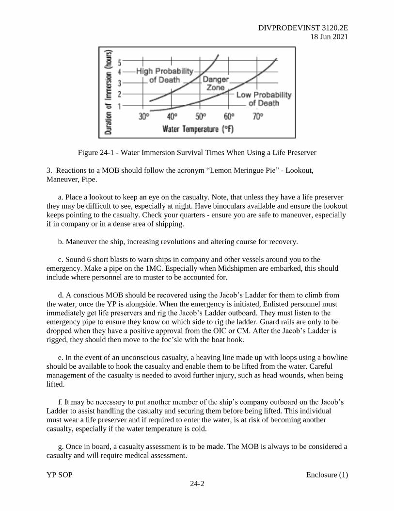
DIVPRODEVINST 3120.2E
18 Jun 2021
YP SOP Enclosure (1)
24-2
Figure 24-1 - Water Immersion Survival Times When Using a Life Preserver
3. Reactions to a MOB should follow the acronym “Lemon Meringue Pie” - Lookout,
Maneuver, Pipe.
a. Place a lookout to keep an eye on the casualty. Note, that unless they have a life preserver
they may be difficult to see, especially at night. Have binoculars available and ensure the lookout
keeps pointing to the casualty. Check your quarters - ensure you are safe to maneuver, especially
if in company or in a dense area of shipping.
b. Maneuver the ship, increasing revolutions and altering course for recovery.
c. Sound 6 short blasts to warn ships in company and other vessels around you to the
emergency. Make a pipe on the 1MC. Especially when Midshipmen are embarked, this should
include where personnel are to muster to be accounted for.
d. A conscious MOB should be recovered using the Jacob’s Ladder for them to climb from
the water, once the YP is alongside. When the emergency is initiated, Enlisted personnel must
immediately get life preservers and rig the Jacob’s Ladder outboard. They must listen to the
emergency pipe to ensure they know on which side to rig the ladder. Guard rails are only to be
dropped when they have a positive approval from the OIC or CM. After the Jacob’s Ladder is
rigged, they should then move to the foc’sle with the boat hook.
e. In the event of an unconscious casualty, a heaving line made up with loops using a bowline
should be available to hook the casualty and enable them to be lifted from the water. Careful
management of the casualty is needed to avoid further injury, such as head wounds, when being
lifted.
f. It may be necessary to put another member of the ship’s company outboard on the Jacob’s
Ladder to assist handling the casualty and securing them before being lifted. This individual
must wear a life preserver and if required to enter the water, is at risk of becoming another
casualty, especially if the water temperature is cold.
g. Once in board, a casualty assessment is to be made. The MOB is always to be considered a
casualty and will require medical assessment.
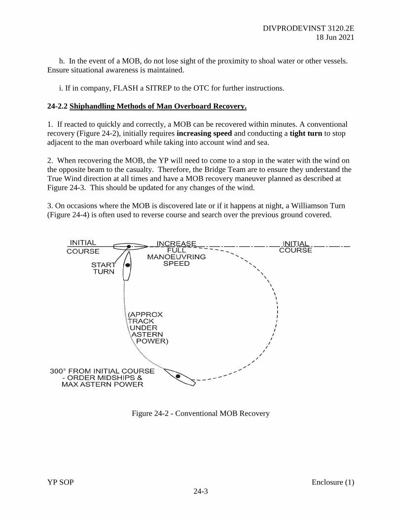
DIVPRODEVINST 3120.2E
18 Jun 2021
YP SOP Enclosure (1)
24-3
h. In the event of a MOB, do not lose sight of the proximity to shoal water or other vessels.
Ensure situational awareness is maintained.
i. If in company, FLASH a SITREP to the OTC for further instructions.
24-2.2 Shiphandling Methods of Man Overboard Recovery.
1. If reacted to quickly and correctly, a MOB can be recovered within minutes. A conventional
recovery (Figure 24-2), initially requires increasing speed and conducting a tight turn to stop
adjacent to the man overboard while taking into account wind and sea.
2. When recovering the MOB, the YP will need to come to a stop in the water with the wind on
the opposite beam to the casualty. Therefore, the Bridge Team are to ensure they understand the
True Wind direction at all times and have a MOB recovery maneuver planned as described at
Figure 24-3. This should be updated for any changes of the wind.
3. On occasions where the MOB is discovered late or if it happens at night, a Williamson Turn
(Figure 24-4) is often used to reverse course and search over the previous ground covered.
Figure 24-2 - Conventional MOB Recovery
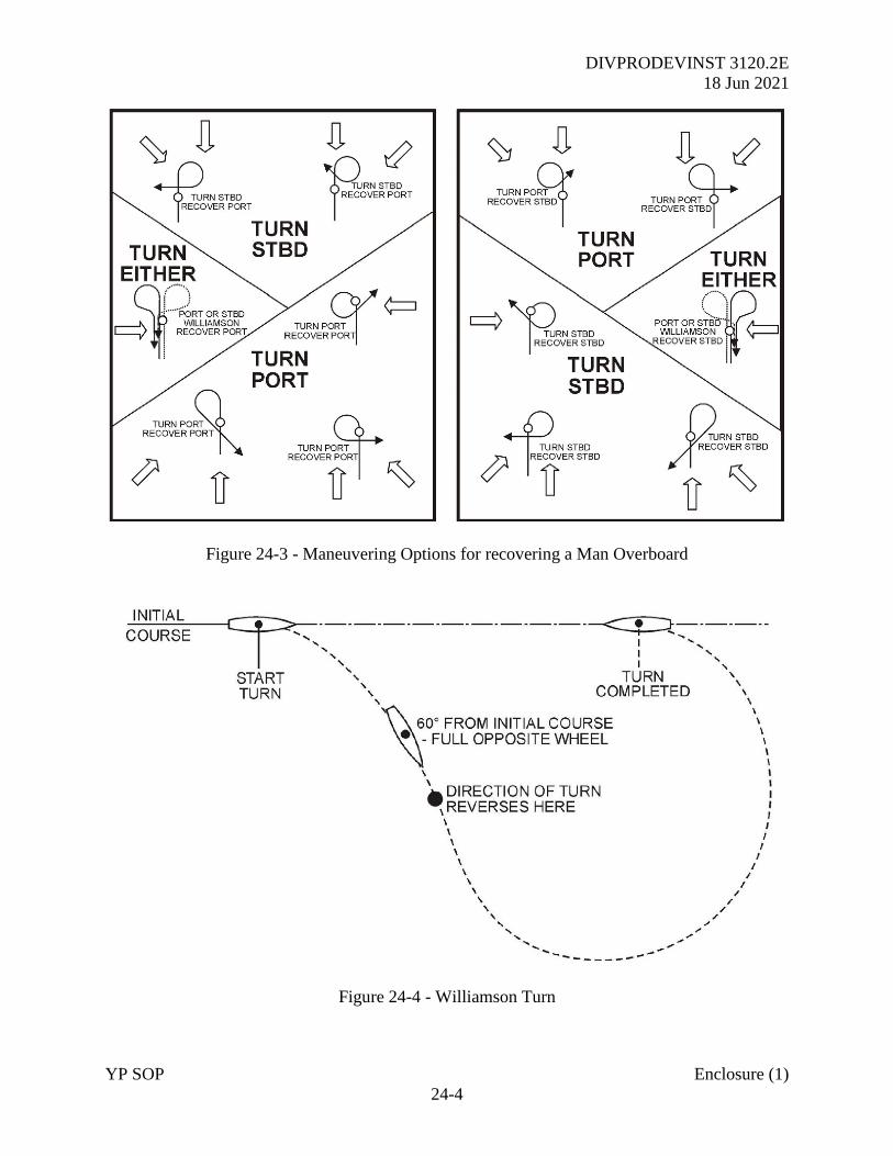
DIVPRODEVINST 3120.2E
18 Jun 2021
YP SOP Enclosure (1)
24-4
Figure 24-3 - Maneuvering Options for recovering a Man Overboard
Figure 24-4 - Williamson Turn
DIVPRODEVINST 3120.2E
18 Jun 2021
YP SOP Enclosure (1)
24-5
24-3 Fires
24-3.1 Classification of Fires
1. Fires are classified as one of three types: A, B, C or some combination of the three. All fires
require fuel, oxygen, and heat to burn. Removal of any one of these three elements will result in
suppression of the fire.
2. Class A fires result from the burning of paper, rags, and similar combustible material. They
are most likely to occur in the crew’s quarters, mess decks, lazarette, chain, and bosun’s locker.
These fires may be fought with water, aqueous film forming foam (AFFF), PKP, and CO2. The
type used depends on availability of gear, accessibility of the compartment, and the composition
of the burning material.
3. Onboard a YP, any Class A fires will usually involve gear such as mattresses, line, etc., which
will smolder long after the surface blaze has been put out. For this reason, it is best to use water
to fight the fire and thoroughly soak the burning material. Remember all water used to fight the
fire drains into the bilge and must be pumped out. While it is in the bilges, it decreases the
reserve buoyancy of the ship.
4. Class B fires involve burning of gas, oil, and similar fluids. They occur most often in the
engineering spaces. These fires may be fought with either AFFF, PKP, FM-200, CO2, or a
combination of these. Which is used will depend on the availability of equipment, the extent of
the fire, and temperature of the compartment.
5. In the early stages of a Class B fire and on other small fires, PKP, FM-200, or CO2 may be
sufficient. If the fire has grown, or has time to heat up the surrounding compartment, it will be
necessary to use AFFF. The AFFF will spread into a blanket that will preclude most re-flash
incidents. AFFF should be applied as a smothering agent and should be 1-2 inches deep using
the installed AFFF hose reel. AFFF should be left in the bilges until all fire hazards have been
pumped over the side. AFFF will reseal if separated. AFFF used to smother the fire should be
washed into the drain and dewatering operations commenced. Fires seeming to be out may start
again from a smoldering fragment or through vapor ignition. Therefore, the final step in fighting
a fire is to set up a re-flash watch for at least an hour after the fire is out. This sentry will not be
stood down without OIC permission.
6. Class C fires are electrical. They are most likely to occur in the pilothouse, CIC, or Galley.
These fires are fought with CO2 or PKP. PKP may cause extensive damage to electrical
equipment within the compartment.
7. Multiple Class fires are those resulting when one class of fire causes another. Any Class A
fire burning through electrical insulation is likely to cause a subsequent Class C fire. A Class C
fire that ignites a pool of oil or other fluid will cause a Class B fire.
8. In combating these types of fires, use the gear required for the higher class of fire. Do not
use water on a Class C fire because you are likely to electrocute yourself.
DIVPRODEVINST 3120.2E
18 Jun 2021
YP SOP Enclosure (1)
24-6
24-3.2 YP General Fire Fighting Procedures (Appendix W). Any smoke detector alarm or
suspected fire must be investigated immediately. On confirming the location and type of fire, the
following steps must be followed to ensure the fire is successfully extinguished. On 703 craft
some smoke detectors are tied into the fuel system to automatically close fuel valves when the
alarm sounds. OIC/AOIC/CM must recognize that they may lose propulsion and generation if
this happens. If the alarm is found to be false, the Engineer needs to know how to reset this
condition quickly.
a. Emergency stop ventilation, shut all internal doors.
b. Sound the general alarm; pass a muster point over the 1MC for embarked MIDN. This
should be a safe location, well clear of the scene of the fire.
c. If at sea, Enlisted Crew are to maintain a continuous and aggressive attack against the seat
of the fire. This action will normally prevent small incidents from escalating.
d. Account for all personnel. The senior MIDN is to muster personnel embarked and report
to the Pilot House when all accounted for.
e. Ensure the compartment has been mechanically and electrically isolated and effective
containment has been established.
f. Where appropriate (Main Space Fires), establish boundary cooling on adjacent bulkheads.
703 class YPs are fitted with multiple AS60 and AS90 fire bulkheads that do not require
immediate boundary cooling.
g. Once the fire has been extinguished, maintain a vigilant watch on the compartment by
placing a fire sentry equipped with the means to refight a fire in the event of a re-flash.
h. Identify a Smoke Clearance Plan. YPs do not have the damage control resources of a
Warship; do not commit personnel to re-entry of a compartment if there is any danger of
atmosphere being out of breathable limits.
i. As soon as possible, pass a FLASH report to the OTC and await assistance. If sea and
weather conditions permit, transfer non-essential personnel to another YP.
j. When in the Annapolis OPAREA, consider proceeding to an emergency anchorage with
personnel available unless deemed able to approach the closest pier.
k. Inform Annapolis Harbor Control (VHF Channel 12) and disembark personnel alongside.
24-3.3 The CM will go to the scene of the incident to direct the damage control effort. The OIC
will remain on the bridge in command.
DIVPRODEVINST 3120.2E
18 Jun 2021
YP SOP Enclosure (1)
24-7
24-3.4 Main Space Fire Fighting Procedures. All class BRAVO Main Space fires will be
fought IAW DIVPRODEVINST 3541 (series) – Main Space Fire Doctrine.
24-3.5 Machinery Breakdown
1. On indication of a machinery breakdown, Look Out, Maneuver and Pipe. Inform other Ships
of the emergency using the ship’s whistle (6 short blasts) and VHF communication as necessary.
a. By day, hoist the FIVE flag. By night, display two all-around red lights arranged
vertically. Side and stern lights should be illuminated if underway.
b. Ensure craft safety by maneuvering clear of shoal water or other vessels as best able.
c. Pass a FLASH SITREP to the OTC. Continue to progress initial casualty actions and
request assistance if required. When available, pass an Estimated Time to Repair (ETR).
d. If the circumstances require, prepare to conduct an emergency anchorage.
2. When safe, system specific immediate controlling actions detailed in the EOSS are to be
followed line by line.
24-4 Emergency Steering
24-4.1 676 Class
1. In the event of the loss of electrical supply to the hydraulic booster pump or following the loss
of pumping capability, the bridge helm unit will automatically revert to the manual hydraulic
pump. This reversionary configuration provides full steering capabilities but at a much slower
speed and higher effort at the wheel. The Panish control lever will be rendered inoperable.
2. In event Pilothouse control units are rendered inoperable due to mechanical malfunction,
steering control must be transferred to the lazarette helm unit following the procedures detailed
in the EOCC documentation. This is accomplished by closing the valves tagged (1), (2), (3), and
(4) and opening valves tagged (5), (6), and (7) located on the steering actuator. Failure to do so
will quickly render the system inoperable by draining the lazarette expansion tank.
24-4.2 703 Class
1. If emergency steering is needed, rudders may be centered using the auxiliary steering pump
(hand wheel) located in the aft steering compartment. In order to configure emergency steering
from the manual helm unit aft, the following steps need be taken:
a. Switch the pump controller from auto to hand mode on both the port and starboard pump
controllers (located on the fwd bulkhead).
b. Close port and starboard supply line valves A1, A2, B1, and B2.
DIVPRODEVINST 3120.2E
18 Jun 2021
YP SOP Enclosure (1)
24-8
c. Open the port and starboard emergency supply line valves L1, L2, K1, and K2.
d. Steering can now be controlled by turning the manual helm pump.
24-5 Collision. The International Rules for the Prevention of Collision at Sea (IRPCS) and the
U.S. Coast Guard Inland Rules should be applied at all times to reduce risk of collision. Any
action to avoid collision should be timely, positive, and seamanlike where possible.
24-5.1 Action by Ships in a Potential Collision Situation or Grounding (Appendix X)
1. Any collision broad on the beam will incur the most damage. If collision cannot be avoided,
as far as possible take such close quarters action to reduce the angle and relative velocity of
impact. Given YP construction, engineering sections and quarters are the weakest craft frames.
2. Close adherence to navigational procedures and standards should minimize risk of grounding.
However, an unavoidable incident occurs, reactions must be quick to protect the craft.
3. In event of either a collision or grounding the following actions are to be taken:
a. Flooding. Water ingress may be caused by single or multiple penetrations to the hull or
damaged valve(s). A continuous and aggressive attack must be sustained against any flood until
contained, the Crew are beaten back or the OIC decides to abandon ship.
b. Small openings can be plugged with rags, Oakum (expands when exposed to water), or
small plugs. Using several plugs together to stem water flow in one location is most effective.
Larger openings may be plugged using more or larger materials such as mattresses or mess deck
tables shored into place.
c. Underwater openings must be plugged first. Thereafter make efforts to plug above
waterline holes on the leeward then the windward sides.
d. As soon as possible, commence dewatering operations to clear the compartment of
floodwater. The OIC/CM must maintain an appraisal of the ship’s stability.
e. If flooding is uncontrollable, the OIC is to drive the craft aground to avoid sinking.
f. Structural Damage on a 676 class is rare because of the craft’s wooden construction. If
it does occur, the affected bulkheads and decks should be shored as soon as possible.
24-6 Abandoning Ship (Appendix Y). In the event of catastrophic damage, remaining onboard
might endanger personnel safety in which case the OIC or CM may give the order to Abandon
Ship in which case it is to be ensured that all stations receive the word as quickly as possible.
24-7 Emergency Service. Certain emergencies may arise which do not directly threaten YP
safety but which, nevertheless, require immediate response because of danger to human life or
DIVPRODEVINST 3120.2E
18 Jun 2021
YP SOP Enclosure (1)
24-9
serious health risks exist. Such situations develop quickly and require positive, quick actions in
order to provide the appropriate degree of emergency service. Those occurrences are most likely
to include serious injury or illness of personnel embarked in a YP or another craft.
24-7.1 Serious Personnel Injury or Illness
1. Action to be taken by the OIC/CM
a. Supervise first aid efforts.
b. If in company with other YPs, pass a FLASH report to the OTC by any means. Expect to
transfer a Corpsman to tend to the casualty if one is deployed with the Squadron. Otherwise,
prepare to make the best possible speed to the nearest port or if necessary, call USCG for
MEDEVAC.
c. Stabilize the casualty as best as possible and follow medical advice received by SATCOM
or phone. Disembark the casualty ashore to EMS personnel when able.
d. Ensure an accurate narrative of events is maintained in the deck log.
24-7.2 Providing Assistance to another YP or Civilian Vessel.
1. Action to be taken for assisting other craft
a. Always be alert for distress signals on other craft or vessels in the vicinity.
b. Be prepared to relay a distress call to the nearest Coast Guard Sector. Render assistance
as directed by the OTC, without endangering the YP.
c. In case of minor distress where no danger to human life exists, call Annapolis Harbor
Control (VHF Channel 12) or the nearest Coast Guard Sector.
d. When providing support to another YP or vessel, do not risk the safety of own craft by
transferring so much damage control equipment so as to impact the ability to manage an incident
on your own vessel.
24-8 Incident Procedures.
1. The primary responsibility of the OIC and CM following an incident is the safety of the
midshipmen if embarked and the safety of the YP. In the event of a navigation incident
(grounding, collision, etc.) underway, the following steps should be taken by the OIC/CM:
a. When in a safe condition alongside, the OIC/CM shall take custody of the charts and all
logs in use. If the chart is required for use, the OIC shall sign in the margin of the chart and the
chart will continue to be used until it can be removed from the pilothouse. No changes to the

DIVPRODEVINST 3120.2E
18 Jun 2021
YP SOP Enclosure (1)
24-10
data on the chart may be made to include erasures, changing course lines, correcting improper
fixes, etc.
b. Watchbills, evolution briefs, checklists and other pertinent documents are to be collected.
3. All digital VMS/ECDIS voyage data shall be downloaded immediately and saved.
4. All materials to be retained by the OIC until PRODEV has cleared them to be used or the
assigned investigating officer has taken custody of the materials.
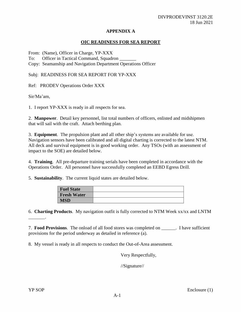
DIVPRODEVINST 3120.2E
18 Jun 2021
YP SOP Enclosure (1)
A-1
APPENDIX A
OIC READINESS FOR SEA REPORT
From: (Name), Officer in Charge, YP-XXX
To: Officer in Tactical Command, Squadron _______
Copy: Seamanship and Navigation Department Operations Officer
Subj: READINESS FOR SEA REPORT FOR YP-XXX
Ref: PRODEV Operations Order XXX
Sir/Ma’am,
1. I report YP-XXX is ready in all respects for sea.
2. Manpower. Detail key personnel, list total numbers of officers, enlisted and midshipmen
that will sail with the craft. Attach berthing plan.
3. Equipment. The propulsion plant and all other ship’s systems are available for use.
Navigation sensors have been calibrated and all digital charting is corrected to the latest NTM.
All deck and survival equipment is in good working order. Any TSOs (with an assessment of
impact to the SOE) are detailed below.
4. Training. All pre-departure training serials have been completed in accordance with the
Operations Order. All personnel have successfully completed an EEBD Egress Drill.
5. Sustainability. The current liquid states are detailed below.
Fuel State
Fresh Water
MSD
6. Charting Products. My navigation outfit is fully corrected to NTM Week xx/xx and LNTM
_______.
7. Food Provisions. The onload of all food stores was completed on ______. I have sufficient
provisions for the period underway as detailed in reference (a).
8. My vessel is ready in all respects to conduct the Out-of-Area assessment.
Very Respectfully,
//Signature//
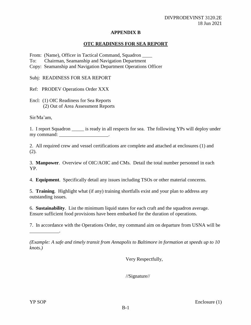
DIVPRODEVINST 3120.2E
18 Jun 2021
YP SOP Enclosure (1)
B-1
APPENDIX B
OTC READINESS FOR SEA REPORT
From: (Name), Officer in Tactical Command, Squadron ____
To: Chairman, Seamanship and Navigation Department
Copy: Seamanship and Navigation Department Operations Officer
Subj: READINESS FOR SEA REPORT
Ref: PRODEV Operations Order XXX
Encl: (1) OIC Readiness for Sea Reports
(2) Out of Area Assessment Reports
Sir/Ma’am,
1. I report Squadron _____ is ready in all respects for sea. The following YPs will deploy under
my command: ____________________.
2. All required crew and vessel certifications are complete and attached at enclosures (1) and
(2).
3. Manpower. Overview of OIC/AOIC and CMs. Detail the total number personnel in each
YP.
4. Equipment. Specifically detail any issues including TSOs or other material concerns.
5. Training. Highlight what (if any) training shortfalls exist and your plan to address any
outstanding issues.
6. Sustainability. List the minimum liquid states for each craft and the squadron average.
Ensure sufficient food provisions have been embarked for the duration of operations.
7. In accordance with the Operations Order, my command aim on departure from USNA will be
____________.
(Example: A safe and timely transit from Annapolis to Baltimore in formation at speeds up to 10
knots.)
Very Respectfully,
//Signature//
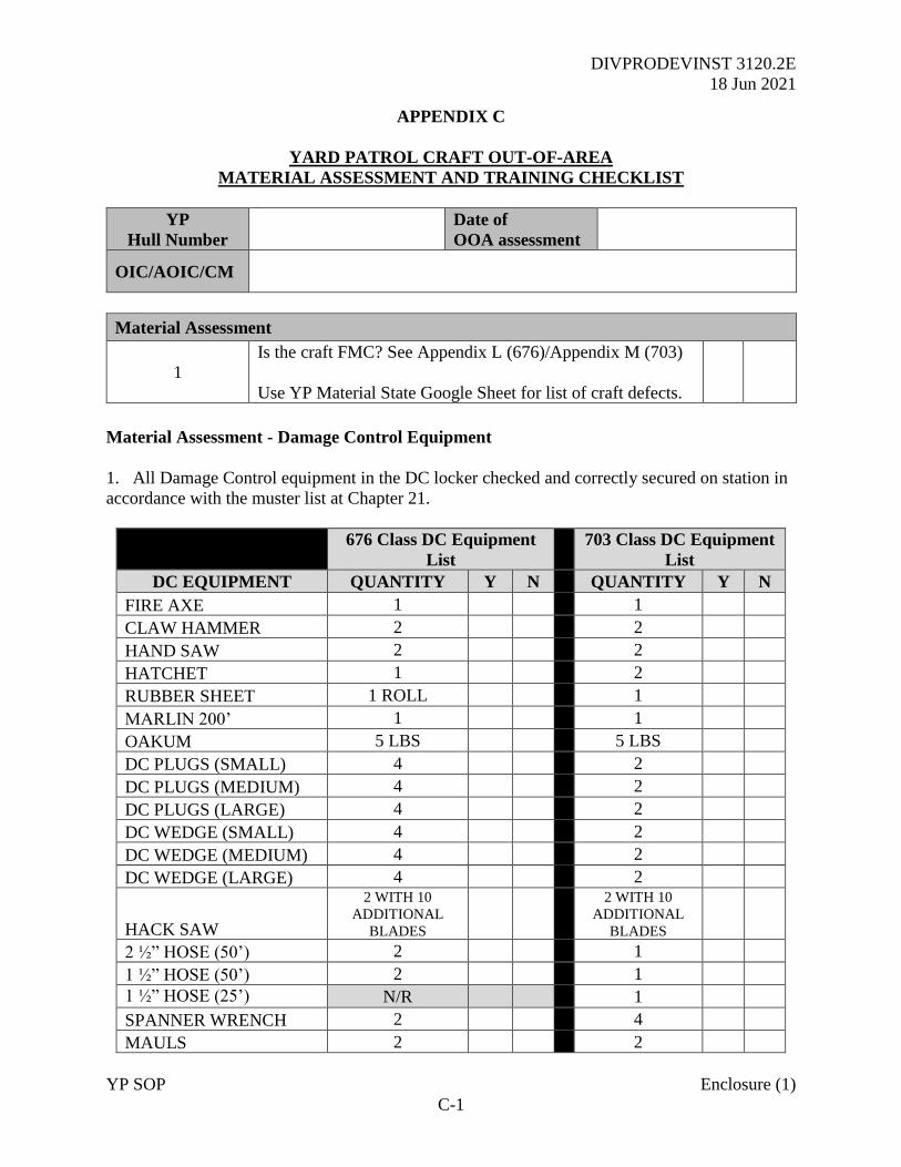
DIVPRODEVINST 3120.2E
18 Jun 2021
YP SOP Enclosure (1)
C-1
APPENDIX C
YARD PATROL CRAFT OUT-OF-AREA
MATERIAL ASSESSMENT AND TRAINING CHECKLIST
YP
Hull Number
Date of
OOA assessment
OIC/AOIC/CM
Material Assessment
1
Is the craft FMC? See Appendix L (676)/Appendix M (703)
Use YP Material State Google Sheet for list of craft defects.
Material Assessment - Damage Control Equipment
1. All Damage Control equipment in the DC locker checked and correctly secured on station in
accordance with the muster list at Chapter 21.
676 Class DC Equipment
List
703 Class DC Equipment
List
DC EQUIPMENT QUANTITY Y N QUANTITY Y N
FIRE AXE 1 1
CLAW HAMMER 2 2
HAND SAW 2 2
HATCHET 1 2
RUBBER SHEET 1 ROLL 1
MARLIN 200’ 1 1
OAKUM 5 LBS 5 LBS
DC PLUGS (SMALL) 4 2
DC PLUGS (MEDIUM) 4 2
DC PLUGS (LARGE) 4 2
DC WEDGE (SMALL) 4 2
DC WEDGE (MEDIUM) 4 2
DC WEDGE (LARGE) 4 2
HACK SAW
2 WITH 10
ADDITIONAL
BLADES
2 WITH 10
ADDITIONAL
BLADES
2 ½” HOSE (50’) 2 1
1 ½” HOSE (50’) 2 1
1 ½” HOSE (25’) N/R 1
SPANNER WRENCH 2 4
MAULS 2 2
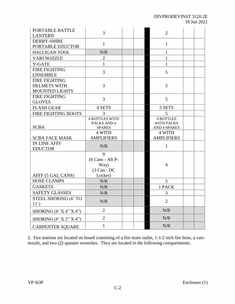
DIVPRODEVINST 3120.2E
18 Jun 2021
YP SOP Enclosure (1)
C-2
PORTABLE BATTLE
LANTERN 3 2
DERBY-SHIRE
PORTABLE EDUCTOR 1 1
HALLIGAN TOOL N/R 1
VARI NOZZLE 2 1
Y-GATE 1 1
FIRE FIGHTING
ENSEMBLE 3 5
FIRE FIGHTING
HELMETS WITH
MOUNTED LIGHTS
3 5
FIRE FIGHTING
GLOVES 3 5
FLASH GEAR 4 SETS 5 SETS
FIRE FIGHTING BOOTS 3 5
SCBA
4 BOTTLES WITH
PACKS AND 4
SPARES
4 BOTTLES
WITH PACKS
AND 4 SPARES
SCBA FACE MASK
4 WITH
AMPLIFIERS
4 WITH
AMPLIFIERS
IN LINE AFFF
EDUCTOR N/R 1
AFFF (5 GAL CANS)
9
(6 Cans - Aft P-
Way)
(3 Can - DC
Locker)
4
HOSE CLAMPS N/R 5
GASKETS N/R 1 PACK
SAFETY GLASSES N/R 3
STEEL SHORING (6’ TO
11’) N/R 2
SHORING (8’ X 4” X 4”) 2 N/R
SHORING (8’ X 2” X 4”) 2 N/R
CARPENTER SQUARE 1 N/R
2. Fire stations are located on board consisting of a fire main outlet, 1-1/2 inch fire hose, a vari-
nozzle, and two (2) spanner wrenches. They are located in the following compartments:

DIVPRODEVINST 3120.2E
18 Jun 2021
YP SOP Enclosure (1)
C-3
676 Class 703 Class
Location Fire Hose Y N Location Hose Length Y N
Foc’sle 2 x 50 foot
Vari nozzle
(2) spanner wrenches
Aft main
deck port
1 x 50 foot
Vari nozzle
(2) spanner wrenches
Fantail 2 x 50 foot Forward
main deck
1 x 50 foot
Vari nozzle
(2) spanner wrenches
Engine
Room
1 x 25 foot Main deck
passageway
1 x 50 foot
Vari nozzle
(2) spanner wrenches
Engine
room access
1 x 50 foot
Vari nozzle
(2) spanner wrenches
Engine
room
1 x 50 foot
Vari nozzle
(2) spanner wrenches
Aft steering 1 x 50 foot
Vari nozzle
(2) spanner wrenches
Classroom
(AFFF / fire
main)
1 x 50 foot
Vari nozzle
(2) spanner wrenches
3. Fire extinguishers carried on board YPs are to have been checked and signed for on the
equipment card at intervals not exceeding 30 days.
PKP Portable Fire Extinguishers
676 Class 703 Class
Location Quantity Y N Location Quantity Y N
Forward passageway 1 Pilothouse 1
Aft passageway 1 Engine Room 1
Galley 1 Aft Steering 1
Engine Room 1
EOS 1
Aft Steering 1
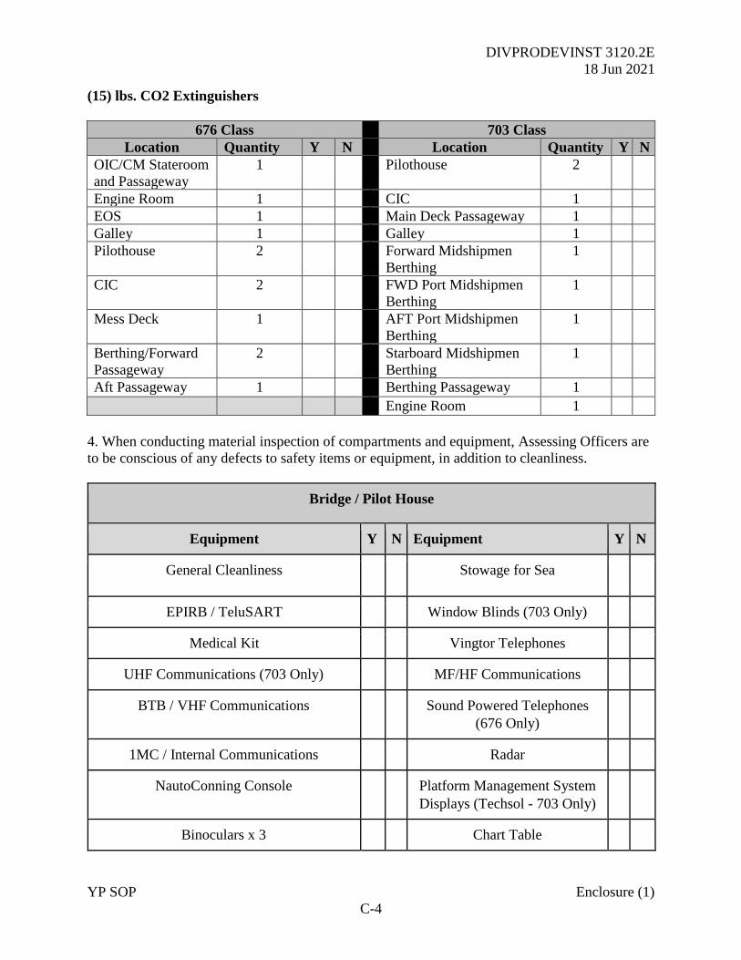
DIVPRODEVINST 3120.2E
18 Jun 2021
YP SOP Enclosure (1)
C-4
(15) lbs. CO2 Extinguishers
676 Class 703 Class
Location Quantity Y N Location Quantity Y N
OIC/CM Stateroom
and Passageway
1 Pilothouse 2
Engine Room 1 CIC 1
EOS 1 Main Deck Passageway 1
Galley 1 Galley 1
Pilothouse 2 Forward Midshipmen
Berthing
1
CIC 2 FWD Port Midshipmen
Berthing
1
Mess Deck 1 AFT Port Midshipmen
Berthing
1
Berthing/Forward
Passageway
2 Starboard Midshipmen
Berthing
1
Aft Passageway 1 Berthing Passageway 1
Engine Room 1
4. When conducting material inspection of compartments and equipment, Assessing Officers are
to be conscious of any defects to safety items or equipment, in addition to cleanliness.
Bridge / Pilot House
Equipment Y N Equipment Y N
General Cleanliness Stowage for Sea
EPIRB / TeluSART Window Blinds (703 Only)
Medical Kit Vingtor Telephones
UHF Communications (703 Only) MF/HF Communications
BTB / VHF Communications Sound Powered Telephones
(676 Only)
1MC / Internal Communications Radar
NautoConning Console Platform Management System
Displays (Techsol - 703 Only)
Binoculars x 3 Chart Table
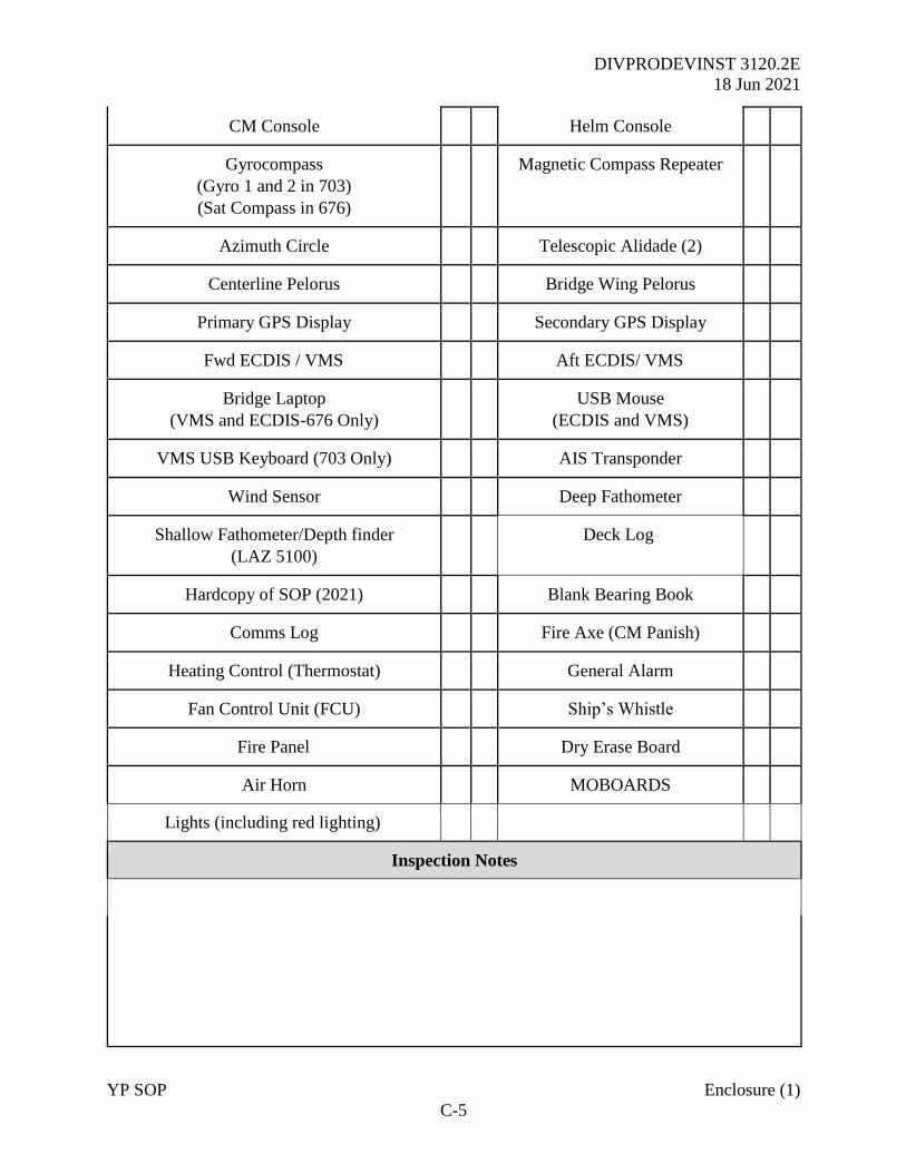
DIVPRODEVINST 3120.2E
18 Jun 2021
YP SOP Enclosure (1)
C-5
CM Console Helm Console
Gyrocompass
(Gyro 1 and 2 in 703)
(Sat Compass in 676)
Magnetic Compass Repeater
Azimuth Circle Telescopic Alidade (2)
Centerline Pelorus Bridge Wing Pelorus
Primary GPS Display Secondary GPS Display
Fwd ECDIS / VMS Aft ECDIS/ VMS
Bridge Laptop
(VMS and ECDIS-676 Only)
USB Mouse
(ECDIS and VMS)
VMS USB Keyboard (703 Only) AIS Transponder
Wind Sensor Deep Fathometer
Shallow Fathometer/Depth finder
(LAZ 5100)
Deck Log
Hardcopy of SOP (2021) Blank Bearing Book
Comms Log Fire Axe (CM Panish)
Heating Control (Thermostat) General Alarm
Fan Control Unit (FCU) Ship’s Whistle
Fire Panel Dry Erase Board
Air Horn MOBOARDS
Lights (including red lighting)
Inspection Notes
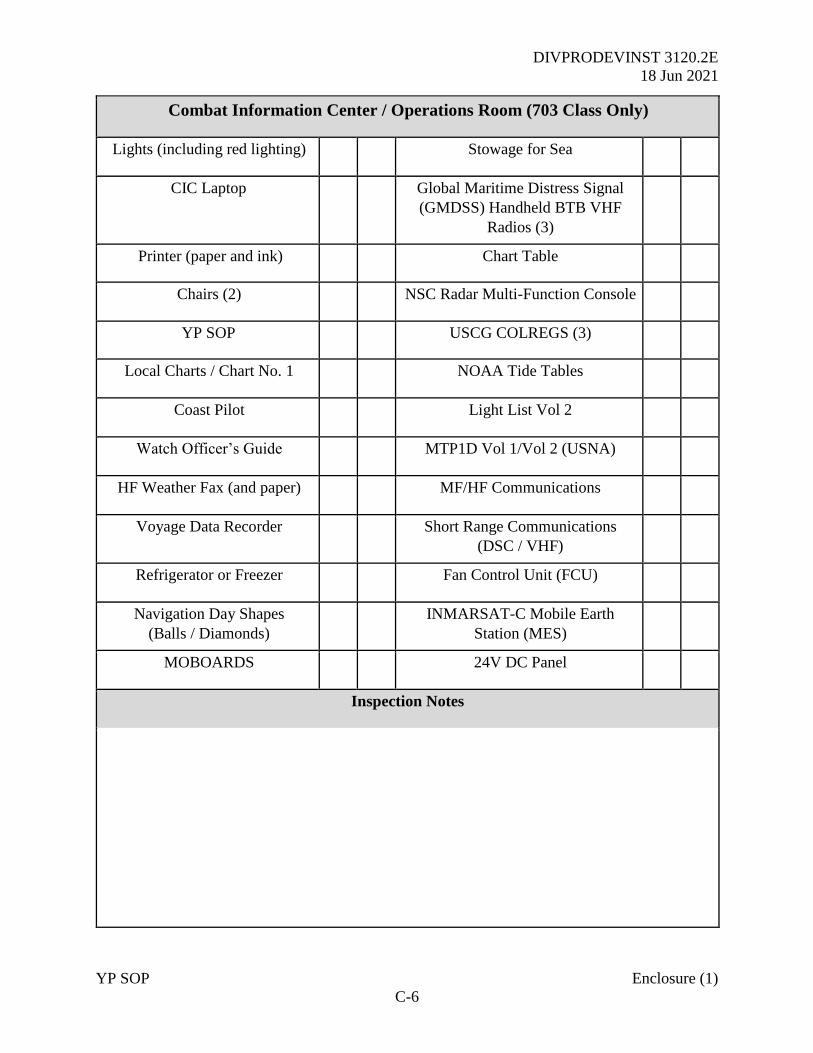
DIVPRODEVINST 3120.2E
18 Jun 2021
YP SOP Enclosure (1)
C-6
Combat Information Center / Operations Room (703 Class Only)
Lights (including red lighting) Stowage for Sea
CIC Laptop Global Maritime Distress Signal
(GMDSS) Handheld BTB VHF
Radios (3)
Printer (paper and ink) Chart Table
Chairs (2) NSC Radar Multi-Function Console
YP SOP USCG COLREGS (3)
Local Charts / Chart No. 1 NOAA Tide Tables
Coast Pilot Light List Vol 2
Watch Officer’s Guide MTP1D Vol 1/Vol 2 (USNA)
HF Weather Fax (and paper) MF/HF Communications
Voyage Data Recorder Short Range Communications
(DSC / VHF)
Refrigerator or Freezer Fan Control Unit (FCU)
Navigation Day Shapes
(Balls / Diamonds)
INMARSAT-C Mobile Earth
Station (MES)
MOBOARDS 24V DC Panel
Inspection Notes
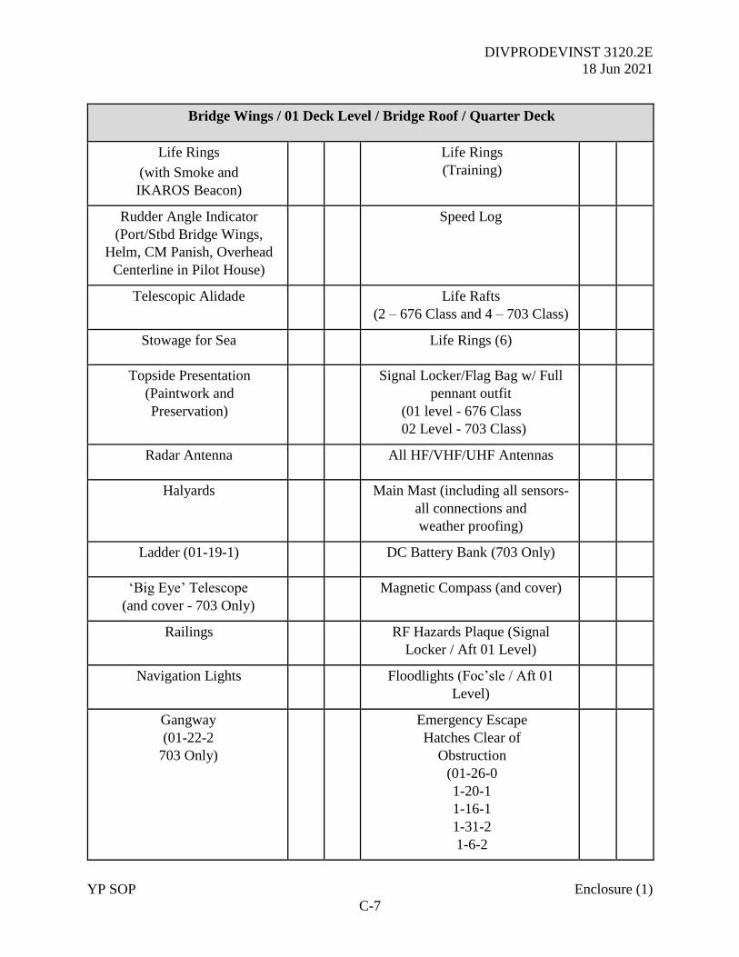
DIVPRODEVINST 3120.2E
18 Jun 2021
YP SOP Enclosure (1)
C-7
Bridge Wings / 01 Deck Level / Bridge Roof / Quarter Deck
Life Rings
(with Smoke and
IKAROS Beacon)
Life Rings
(Training)
Rudder Angle Indicator
(Port/Stbd Bridge Wings,
Helm, CM Panish, Overhead
Centerline in Pilot House)
Speed Log
Telescopic Alidade Life Rafts
(2 – 676 Class and 4 – 703 Class)
Stowage for Sea Life Rings (6)
Topside Presentation
(Paintwork and
Preservation)
Signal Locker/Flag Bag w/ Full
pennant outfit
(01 level - 676 Class
02 Level - 703 Class)
Radar Antenna All HF/VHF/UHF Antennas
Halyards Main Mast (including all sensors-
all connections and
weather proofing)
Ladder (01-19-1) DC Battery Bank (703 Only)
‘Big Eye’ Telescope
(and cover - 703 Only)
Magnetic Compass (and cover)
Railings RF Hazards Plaque (Signal
Locker / Aft 01 Level)
Navigation Lights Floodlights (Foc’sle / Aft 01
Level)
Gangway
(01-22-2
703 Only)
Emergency Escape
Hatches Clear of
Obstruction
(01-26-0
1-20-1
1-16-1
1-31-2
1-6-2
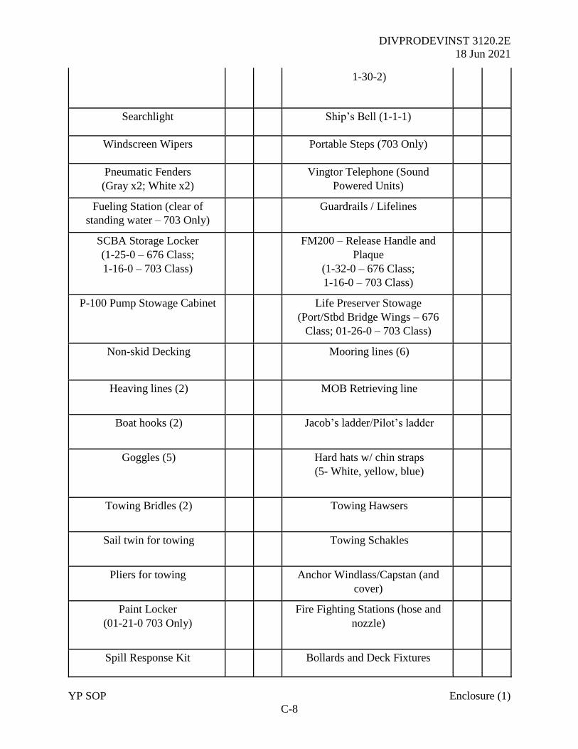
DIVPRODEVINST 3120.2E
18 Jun 2021
YP SOP Enclosure (1)
C-8
1-30-2)
Searchlight Ship’s Bell (1-1-1)
Windscreen Wipers Portable Steps (703 Only)
Pneumatic Fenders
(Gray x2; White x2)
Vingtor Telephone (Sound
Powered Units)
Fueling Station (clear of
standing water – 703 Only)
Guardrails / Lifelines
SCBA Storage Locker
(1-25-0 – 676 Class;
1-16-0 – 703 Class)
FM200 – Release Handle and
Plaque
(1-32-0 – 676 Class;
1-16-0 – 703 Class)
P-100 Pump Stowage Cabinet Life Preserver Stowage
(Port/Stbd Bridge Wings – 676
Class; 01-26-0 – 703 Class)
Non-skid Decking Mooring lines (6)
Heaving lines (2)
MOB Retrieving line
Boat hooks (2)
Jacob’s ladder/Pilot’s ladder
Goggles (5)
Hard hats w/ chin straps
(5- White, yellow, blue)
Towing Bridles (2)
Towing Hawsers
Sail twin for towing
Towing Schakles
Pliers for towing Anchor Windlass/Capstan (and
cover)
Paint Locker
(01-21-0 703 Only)
Fire Fighting Stations (hose and
nozzle)
Spill Response Kit Bollards and Deck Fixtures
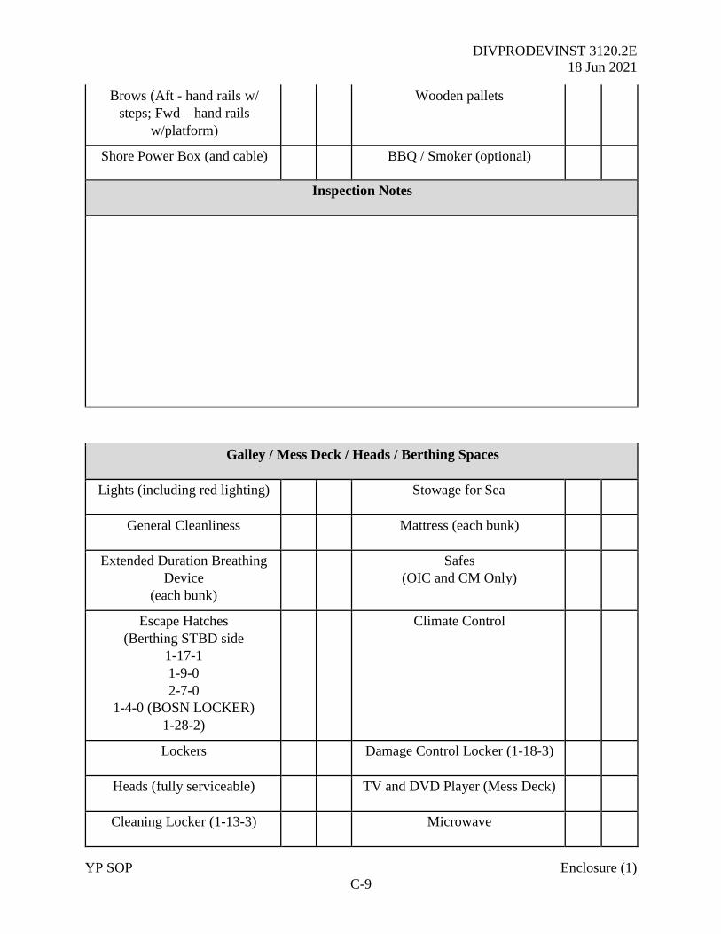
DIVPRODEVINST 3120.2E
18 Jun 2021
YP SOP Enclosure (1)
C-9
Brows (Aft - hand rails w/
steps; Fwd – hand rails
w/platform)
Wooden pallets
Shore Power Box (and cable) BBQ / Smoker (optional)
Inspection Notes
Galley / Mess Deck / Heads / Berthing Spaces
Lights (including red lighting) Stowage for Sea
General Cleanliness Mattress (each bunk)
Extended Duration Breathing
Device
(each bunk)
Safes
(OIC and CM Only)
Escape Hatches
(Berthing STBD side
1-17-1
1-9-0
2-7-0
1-4-0 (BOSN LOCKER)
1-28-2)
Climate Control
Lockers Damage Control Locker (1-18-3)
Heads (fully serviceable) TV and DVD Player (Mess Deck)
Cleaning Locker (1-13-3) Microwave
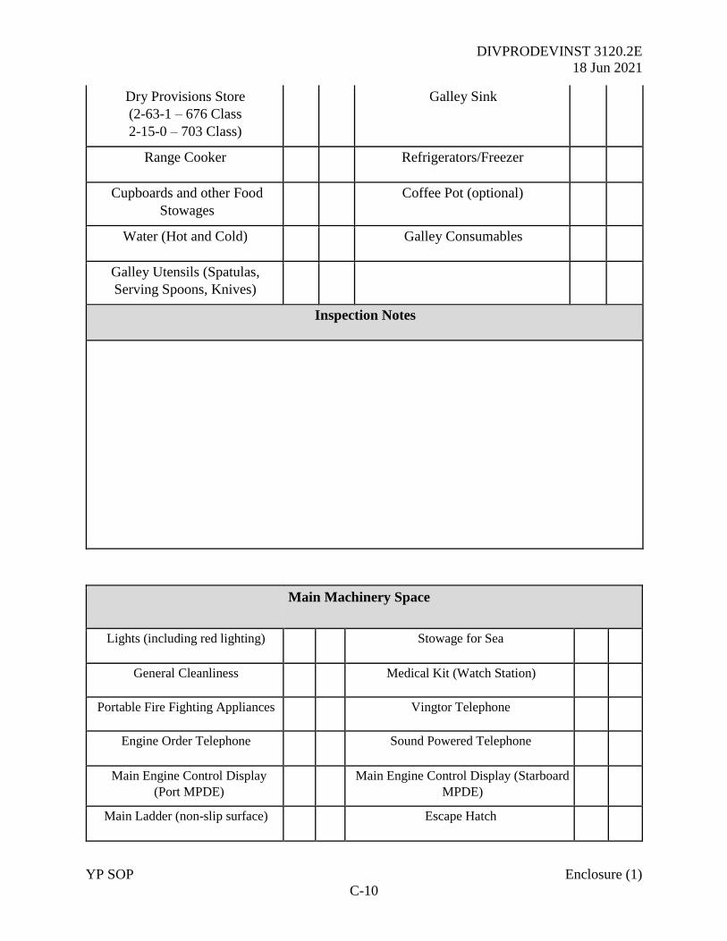
DIVPRODEVINST 3120.2E
18 Jun 2021
YP SOP Enclosure (1)
C-10
Dry Provisions Store
(2-63-1 – 676 Class
2-15-0 – 703 Class)
Galley Sink
Range Cooker Refrigerators/Freezer
Cupboards and other Food
Stowages
Coffee Pot (optional)
Water (Hot and Cold) Galley Consumables
Galley Utensils (Spatulas,
Serving Spoons, Knives)
Inspection Notes
Main Machinery Space
Lights (including red lighting) Stowage for Sea
General Cleanliness Medical Kit (Watch Station)
Portable Fire Fighting Appliances Vingtor Telephone
Engine Order Telephone Sound Powered Telephone
Main Engine Control Display
(Port MPDE)
Main Engine Control Display (Starboard
MPDE)
Main Ladder (non-slip surface) Escape Hatch
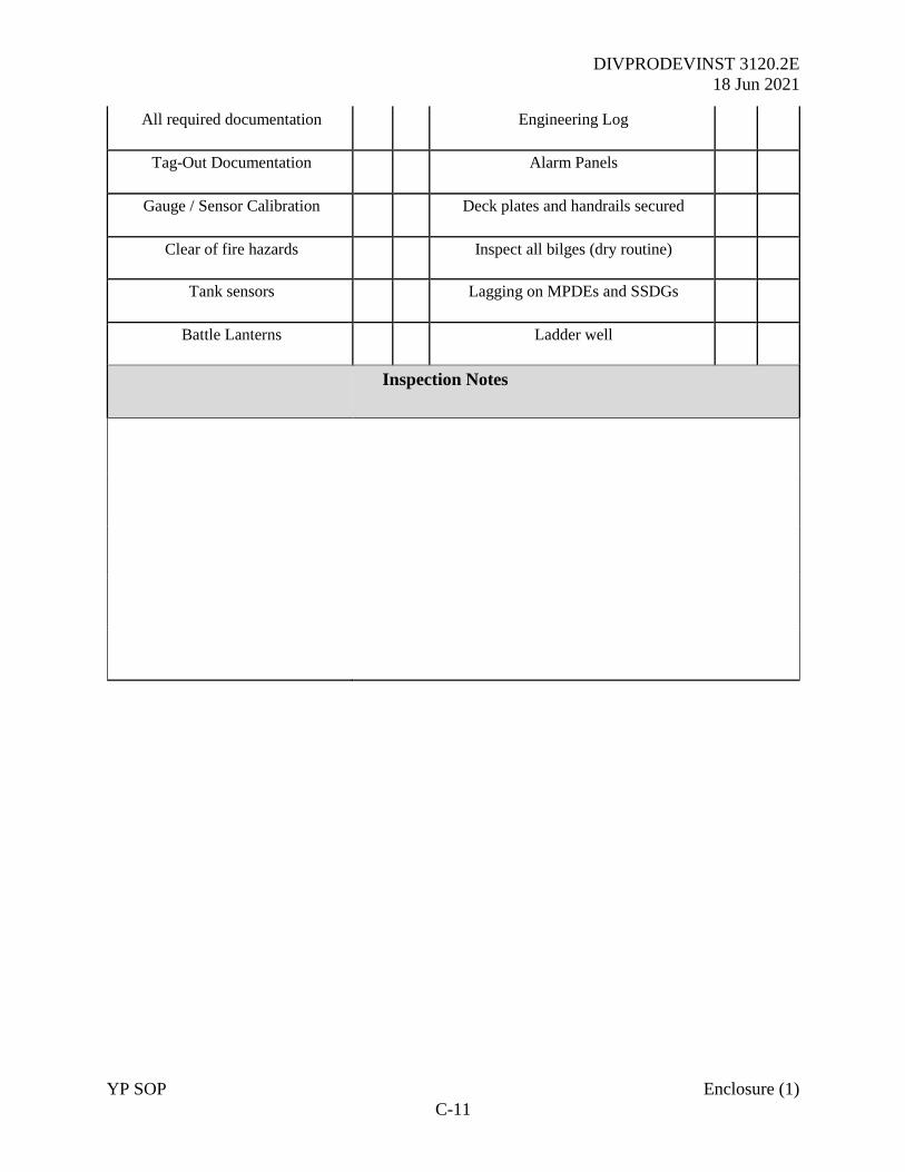
DIVPRODEVINST 3120.2E
18 Jun 2021
YP SOP Enclosure (1)
C-11
All required documentation Engineering Log
Tag-Out Documentation Alarm Panels
Gauge / Sensor Calibration Deck plates and handrails secured
Clear of fire hazards Inspect all bilges (dry routine)
Tank sensors Lagging on MPDEs and SSDGs
Battle Lanterns Ladder well
Inspection Notes

DIVPRODEVINST 3120.2E
18 Jun 2021
YP SOP Enclosure (1)
C-12
Underway Inspection
Navigation Administration
1 Are all Navigation Charts corrected and signed utilizing the
chart preparation checklist (Appendix E)?
2 Was the Navigation Brief completed correctly?
3 Is VMS/ECDIS correctly configured IAW Navigation
Standards?
4 Was the track uploaded into VMS/ECDIS? At the CM chair? At the Nav table?
5 Was a signed watchbill posted for inspection?
Engineering
6 Were MLOCs completed and signed by the Engineer, CM,
and OIC?
7
Was the Main Machinery Space in a good condition, free of
debris, leaks, flammable liquids, and hazards with
equipment in good working order?
8 Were all logs available for inspection and correctly
annotated by the Engineer?
9 Is there any defective equipment not recorded as OOC or
covered by a current TSO?
Damage Control
10
Is all portable firefighting equipment on station and in-date
for the periodic checks?
Verify DC equipment in accordance with DC requirements
Communications
11 Can the crew proficiently operate all external comms
equipment including HF, VHF, SATCOM, and AIS?
Survival Equipment
12 Is the Flare Pack onboard the craft?
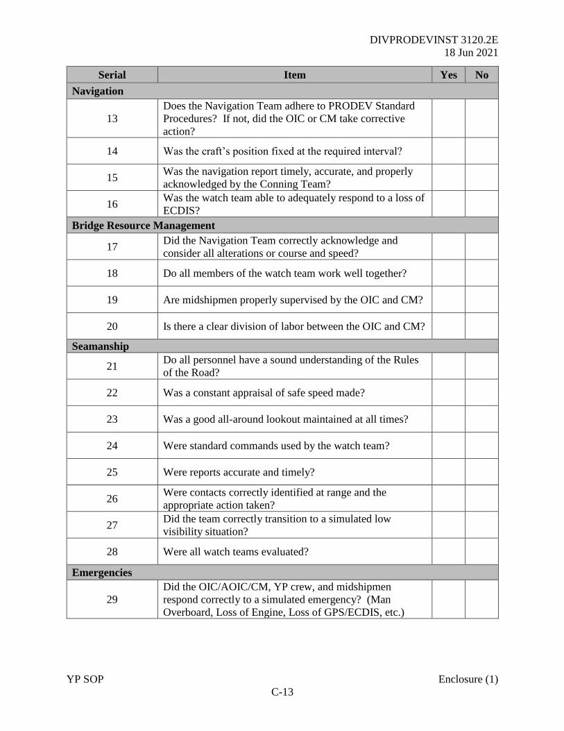
DIVPRODEVINST 3120.2E
18 Jun 2021
YP SOP Enclosure (1)
C-13
Serial Item Yes No
Navigation
13
Does the Navigation Team adhere to PRODEV Standard
Procedures? If not, did the OIC or CM take corrective
action?
14 Was the craft’s position fixed at the required interval?
15 Was the navigation report timely, accurate, and properly
acknowledged by the Conning Team?
16 Was the watch team able to adequately respond to a loss of
ECDIS?
Bridge Resource Management
17 Did the Navigation Team correctly acknowledge and
consider all alterations or course and speed?
18 Do all members of the watch team work well together?
19 Are midshipmen properly supervised by the OIC and CM?
20 Is there a clear division of labor between the OIC and CM?
Seamanship
21 Do all personnel have a sound understanding of the Rules
of the Road?
22 Was a constant appraisal of safe speed made?
23 Was a good all-around lookout maintained at all times?
24 Were standard commands used by the watch team?
25 Were reports accurate and timely?
26 Were contacts correctly identified at range and the
appropriate action taken?
27 Did the team correctly transition to a simulated low
visibility situation?
28 Were all watch teams evaluated?
Emergencies
29
Did the OIC/AOIC/CM, YP crew, and midshipmen
respond correctly to a simulated emergency? (Man
Overboard, Loss of Engine, Loss of GPS/ECDIS, etc.)
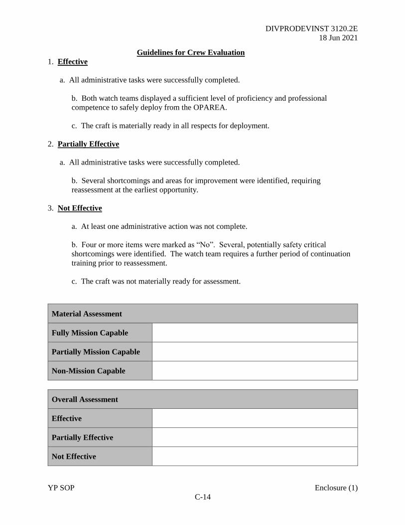
DIVPRODEVINST 3120.2E
18 Jun 2021
YP SOP Enclosure (1)
C-14
Guidelines for Crew Evaluation
1. Effective
a. All administrative tasks were successfully completed.
b. Both watch teams displayed a sufficient level of proficiency and professional
competence to safely deploy from the OPAREA.
c. The craft is materially ready in all respects for deployment.
2. Partially Effective
a. All administrative tasks were successfully completed.
b. Several shortcomings and areas for improvement were identified, requiring
reassessment at the earliest opportunity.
3. Not Effective
a. At least one administrative action was not complete.
b. Four or more items were marked as “No”. Several, potentially safety critical
shortcomings were identified. The watch team requires a further period of continuation
training prior to reassessment.
c. The craft was not materially ready for assessment.
Material Assessment
Fully Mission Capable
Partially Mission Capable
Non-Mission Capable
Overall Assessment
Effective
Partially Effective
Not Effective
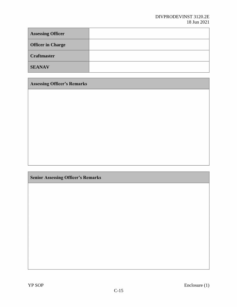
DIVPRODEVINST 3120.2E
18 Jun 2021
YP SOP Enclosure (1)
C-15
Assessing Officer
Officer in Charge
Craftmaster
SEANAV
Assessing Officer’s Remarks
Senior Assessing Officer’s Remarks
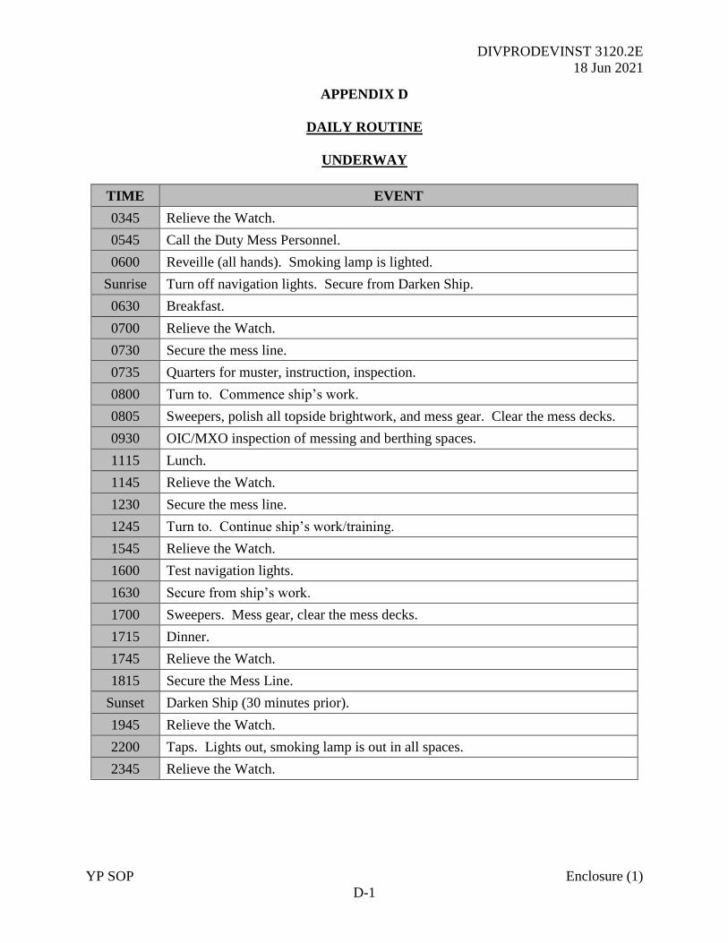
DIVPRODEVINST 3120.2E
18 Jun 2021
YP SOP Enclosure (1)
D-1
APPENDIX D
DAILY ROUTINE
UNDERWAY
TIME EVENT
0345 Relieve the Watch.
0545 Call the Duty Mess Personnel.
0600 Reveille (all hands). Smoking lamp is lighted.
Sunrise Turn off navigation lights. Secure from Darken Ship.
0630 Breakfast.
0700 Relieve the Watch.
0730 Secure the mess line.
0735 Quarters for muster, instruction, inspection.
0800 Turn to. Commence ship’s work.
0805 Sweepers, polish all topside brightwork, and mess gear. Clear the mess decks.
0930 OIC/MXO inspection of messing and berthing spaces.
1115 Lunch.
1145 Relieve the Watch.
1230 Secure the mess line.
1245 Turn to. Continue ship’s work/training.
1545 Relieve the Watch.
1600 Test navigation lights.
1630 Secure from ship’s work.
1700 Sweepers. Mess gear, clear the mess decks.
1715 Dinner.
1745 Relieve the Watch.
1815 Secure the Mess Line.
Sunset Darken Ship (30 minutes prior).
1945 Relieve the Watch.
2200 Taps. Lights out, smoking lamp is out in all spaces.
2345 Relieve the Watch.
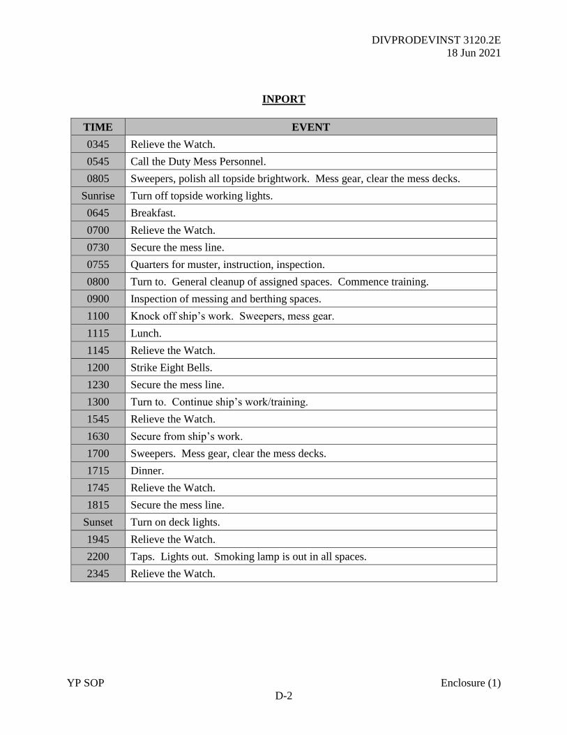
DIVPRODEVINST 3120.2E
18 Jun 2021
YP SOP Enclosure (1)
D-2
INPORT
TIME EVENT
0345 Relieve the Watch.
0545 Call the Duty Mess Personnel.
0805 Sweepers, polish all topside brightwork. Mess gear, clear the mess decks.
Sunrise Turn off topside working lights.
0645 Breakfast.
0700 Relieve the Watch.
0730 Secure the mess line.
0755 Quarters for muster, instruction, inspection.
0800 Turn to. General cleanup of assigned spaces. Commence training.
0900 Inspection of messing and berthing spaces.
1100 Knock off ship’s work. Sweepers, mess gear.
1115 Lunch.
1145 Relieve the Watch.
1200 Strike Eight Bells.
1230 Secure the mess line.
1300 Turn to. Continue ship’s work/training.
1545 Relieve the Watch.
1630 Secure from ship’s work.
1700 Sweepers. Mess gear, clear the mess decks.
1715 Dinner.
1745 Relieve the Watch.
1815 Secure the mess line.
Sunset Turn on deck lights.
1945 Relieve the Watch.
2200 Taps. Lights out. Smoking lamp is out in all spaces.
2345 Relieve the Watch.
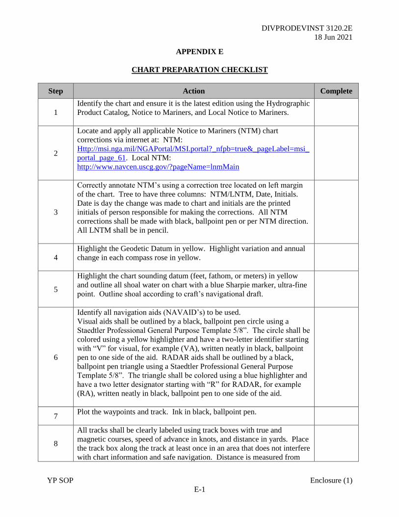
DIVPRODEVINST 3120.2E
18 Jun 2021
YP SOP Enclosure (1)
E-1
APPENDIX E
CHART PREPARATION CHECKLIST
Step Action Complete
1
Identify the chart and ensure it is the latest edition using the Hydrographic
Product Catalog, Notice to Mariners, and Local Notice to Mariners.
2
Locate and apply all applicable Notice to Mariners (NTM) chart
corrections via internet at: NTM:
Http://msi.nga.mil/NGAPortal/MSI.portal?_nfpb=true&_pageLabel=msi_
portal_page_61. Local NTM:
http://www.navcen.uscg.gov/?pageName=lnmMain
3
Correctly annotate NTM’s using a correction tree located on left margin
of the chart. Tree to have three columns: NTM/LNTM, Date, Initials.
Date is day the change was made to chart and initials are the printed
initials of person responsible for making the corrections. All NTM
corrections shall be made with black, ballpoint pen or per NTM direction.
All LNTM shall be in pencil.
4
Highlight the Geodetic Datum in yellow. Highlight variation and annual
change in each compass rose in yellow.
5
Highlight the chart sounding datum (feet, fathom, or meters) in yellow
and outline all shoal water on chart with a blue Sharpie marker, ultra-fine
point. Outline shoal according to craft’s navigational draft.
6
Identify all navigation aids (NAVAID’s) to be used.
Visual aids shall be outlined by a black, ballpoint pen circle using a
Staedtler Professional General Purpose Template 5/8”. The circle shall be
colored using a yellow highlighter and have a two-letter identifier starting
with “V” for visual, for example (VA), written neatly in black, ballpoint
pen to one side of the aid. RADAR aids shall be outlined by a black,
ballpoint pen triangle using a Staedtler Professional General Purpose
Template 5/8”. The triangle shall be colored using a blue highlighter and
have a two letter designator starting with “R” for RADAR, for example
(RA), written neatly in black, ballpoint pen to one side of the aid.
7 Plot the waypoints and track. Ink in black, ballpoint pen.
8
All tracks shall be clearly labeled using track boxes with true and
magnetic courses, speed of advance in knots, and distance in yards. Place
the track box along the track at least once in an area that does not interfere
with chart information and safe navigation. Distance is measured from
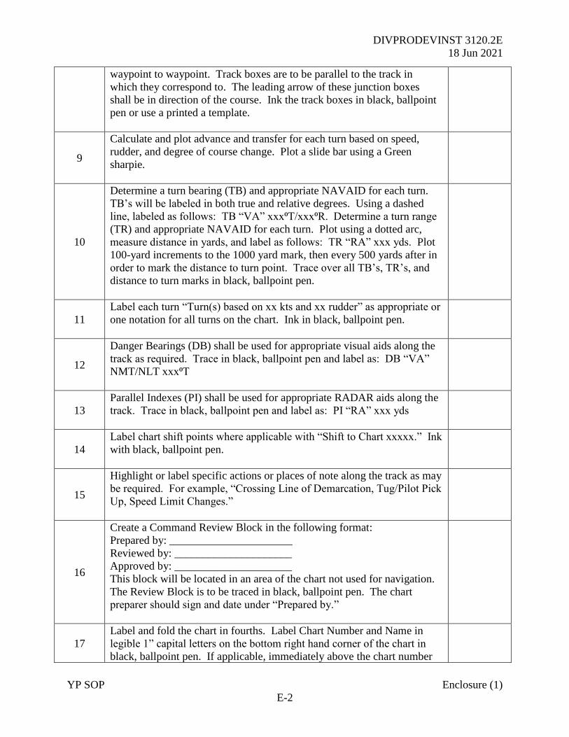
DIVPRODEVINST 3120.2E
18 Jun 2021
YP SOP Enclosure (1)
E-2
waypoint to waypoint. Track boxes are to be parallel to the track in
which they correspond to. The leading arrow of these junction boxes
shall be in direction of the course. Ink the track boxes in black, ballpoint
pen or use a printed a template.
9
Calculate and plot advance and transfer for each turn based on speed,
rudder, and degree of course change. Plot a slide bar using a Green
sharpie.
10
Determine a turn bearing (TB) and appropriate NAVAID for each turn.
TB’s will be labeled in both true and relative degrees. Using a dashed
line, labeled as follows: TB “VA” xxx⁰T/xxx⁰R. Determine a turn range
(TR) and appropriate NAVAID for each turn. Plot using a dotted arc,
measure distance in yards, and label as follows: TR “RA” xxx yds. Plot
100-yard increments to the 1000 yard mark, then every 500 yards after in
order to mark the distance to turn point. Trace over all TB’s, TR’s, and
distance to turn marks in black, ballpoint pen.
11
Label each turn “Turn(s) based on xx kts and xx rudder” as appropriate or
one notation for all turns on the chart. Ink in black, ballpoint pen.
12
Danger Bearings (DB) shall be used for appropriate visual aids along the
track as required. Trace in black, ballpoint pen and label as: DB “VA”
NMT/NLT xxx⁰T
13
Parallel Indexes (PI) shall be used for appropriate RADAR aids along the
track. Trace in black, ballpoint pen and label as: PI “RA” xxx yds
14
Label chart shift points where applicable with “Shift to Chart xxxxx.” Ink
with black, ballpoint pen.
15
Highlight or label specific actions or places of note along the track as may
be required. For example, “Crossing Line of Demarcation, Tug/Pilot Pick
Up, Speed Limit Changes.”
16
Create a Command Review Block in the following format:
Prepared by: ______________________
Reviewed by: _____________________
Approved by: _____________________
This block will be located in an area of the chart not used for navigation.
The Review Block is to be traced in black, ballpoint pen. The chart
preparer should sign and date under “Prepared by.”
17
Label and fold the chart in fourths. Label Chart Number and Name in
legible 1” capital letters on the bottom right hand corner of the chart in
black, ballpoint pen. If applicable, immediately above the chart number
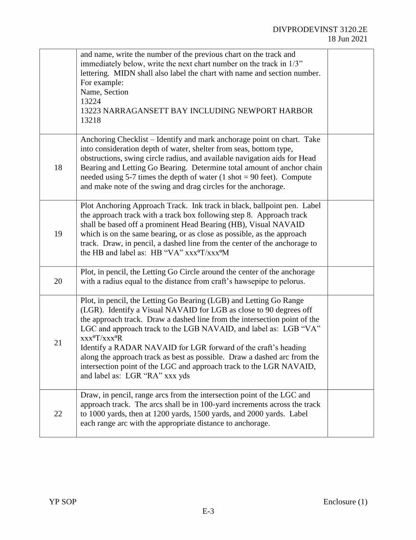
DIVPRODEVINST 3120.2E
18 Jun 2021
YP SOP Enclosure (1)
E-3
and name, write the number of the previous chart on the track and
immediately below, write the next chart number on the track in 1/3”
lettering. MIDN shall also label the chart with name and section number.
For example:
Name, Section
13224
13223 NARRAGANSETT BAY INCLUDING NEWPORT HARBOR
13218
18
Anchoring Checklist – Identify and mark anchorage point on chart. Take
into consideration depth of water, shelter from seas, bottom type,
obstructions, swing circle radius, and available navigation aids for Head
Bearing and Letting Go Bearing. Determine total amount of anchor chain
needed using 5-7 times the depth of water (1 shot = 90 feet). Compute
and make note of the swing and drag circles for the anchorage.
19
Plot Anchoring Approach Track. Ink track in black, ballpoint pen. Label
the approach track with a track box following step 8. Approach track
shall be based off a prominent Head Bearing (HB), Visual NAVAID
which is on the same bearing, or as close as possible, as the approach
track. Draw, in pencil, a dashed line from the center of the anchorage to
the HB and label as: HB “VA” xxx⁰T/xxx⁰M
20
Plot, in pencil, the Letting Go Circle around the center of the anchorage
with a radius equal to the distance from craft’s hawsepipe to pelorus.
21
Plot, in pencil, the Letting Go Bearing (LGB) and Letting Go Range
(LGR). Identify a Visual NAVAID for LGB as close to 90 degrees off
the approach track. Draw a dashed line from the intersection point of the
LGC and approach track to the LGB NAVAID, and label as: LGB “VA”
xxx⁰T/xxx⁰R
Identify a RADAR NAVAID for LGR forward of the craft’s heading
along the approach track as best as possible. Draw a dashed arc from the
intersection point of the LGC and approach track to the LGR NAVAID,
and label as: LGR “RA” xxx yds
22
Draw, in pencil, range arcs from the intersection point of the LGC and
approach track. The arcs shall be in 100-yard increments across the track
to 1000 yards, then at 1200 yards, 1500 yards, and 2000 yards. Label
each range arc with the appropriate distance to anchorage.
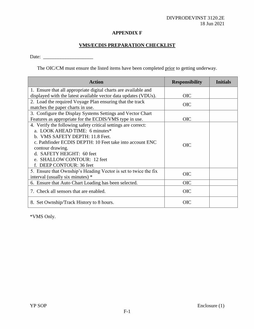
DIVPRODEVINST 3120.2E
18 Jun 2021
YP SOP Enclosure (1)
F-1
APPENDIX F
VMS/ECDIS PREPARATION CHECKLIST
Date: ____________________
The OIC/CM must ensure the listed items have been completed prior to getting underway.
Action Responsibility Initials
1. Ensure that all appropriate digital charts are available and
displayed with the latest available vector data updates (VDUs).
OIC
2. Load the required Voyage Plan ensuring that the track
matches the paper charts in use. OIC
3. Configure the Display Systems Settings and Vector Chart
Features as appropriate for the ECDIS/VMS type in use.
OIC
4. Verify the following safety critical settings are correct:
a. LOOK AHEAD TIME: 6 minutes*
b. VMS SAFETY DEPTH: 11.8 Feet.
c. Pathfinder ECDIS DEPTH: 10 Feet take into account ENC
contour drawing.
d. SAFETY HEIGHT: 60 feet
e. SHALLOW CONTOUR: 12 feet
f. DEEP CONTOUR: 36 feet
OIC
5. Ensure that Ownship’s Heading Vector is set to twice the fix
interval (usually six minutes) * OIC
6. Ensure that Auto Chart Loading has been selected. OIC
7. Check all sensors that are enabled. OIC
8. Set Ownship/Track History to 8 hours. OIC
*VMS Only.
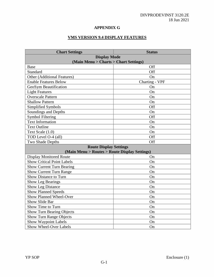
DIVPRODEVINST 3120.2E
18 Jun 2021
YP SOP Enclosure (1)
G-1
APPENDIX G
VMS VERSION 9.4 DISPLAY FEATURES
Chart Settings Status
Display Mode
(Main Menu > Charts > Chart Settings)
Base Off
Standard Off
Other (Additional Features) On
Enable Features Below Charting - VPF
GeoSym Beautification On
Light Features On
Overscale Pattern On
Shallow Pattern On
Simplified Symbols Off
Soundings and Depths On
Symbol Filtering Off
Text Information On
Text Outline On
Text Scale (1.0) On
TOD Level O-4 (all) Off
Two Shade Depths Off
Route Display Settings
(Main Menu > Routes > Route Display Settings)
Display Monitored Route On
Show Critical Point Labels On
Show Current Turn Bearing On
Show Current Turn Range On
Show Distance to Turn On
Show Leg Bearings On
Show Leg Distance On
Show Planned Speeds On
Show Planned Wheel-Over On
Show Slide Bar On
Show Time to Turn On
Show Turn Bearing Objects On
Show Turn Range Objects On
Show Waypoint Labels On
Show Wheel-Over Labels On
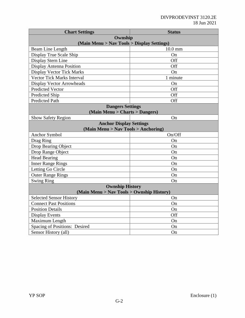
DIVPRODEVINST 3120.2E
18 Jun 2021
YP SOP Enclosure (1)
G-2
Chart Settings Status
Ownship
(Main Menu > Nav Tools > Display Settings)
Beam Line Length 10.0 mm
Display True Scale Ship On
Display Stern Line Off
Display Antenna Position Off
Display Vector Tick Marks On
Vector Tick Marks Interval 1 minute
Display Vector Arrowheads On
Predicted Vector Off
Predicted Ship Off
Predicted Path Off
Dangers Settings
(Main Menu > Charts > Dangers)
Show Safety Region On
Anchor Display Settings
(Main Menu > Nav Tools > Anchoring)
Anchor Symbol On/Off
Drag Ring On
Drop Bearing Object On
Drop Range Object On
Head Bearing On
Inner Range Rings On
Letting Go Circle On
Outer Range Rings On
Swing Ring On
Ownship History
(Main Menu > Nav Tools > Ownship History)
Selected Sensor History On
Connect Past Positions On
Position Details On
Display Events Off
Maximum Length On
Spacing of Positions: Desired On
Sensor History (all) On
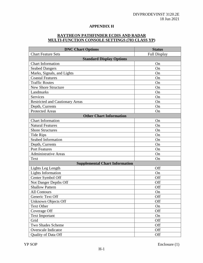
DIVPRODEVINST 3120.2E
18 Jun 2021
YP SOP Enclosure (1)
H-1
APPENDIX H
RAYTHEON PATHFINDER ECDIS AND RADAR
MULTI-FUNCTION CONSOLE SETTINGS (703 CLASS YP)
DNC Chart Options Status
Chart Feature Sets Full Display
Standard Display Options
Chart Information On
Seabed Dangers On
Marks, Signals, and Lights On
Coastal Features On
Traffic Routes On
New Shore Structure On
Landmarks On
Services On
Restricted and Cautionary Areas On
Depth, Currents On
Protected Areas On
Other Chart Information
Chart Information On
Natural Features On
Shore Structures On
Tide Rips On
Seabed Information On
Depth, Currents On
Port Features On
Administrative Areas On
Text On
Supplemental Chart Information
Lights Leg Length Off
Lights Information On
Center Symbol Off Off
Not Danger Depths Off Off
Shallow Pattern Off
All Contours On
Generic Text Off Off
Unknown Objects Off Off
Text Other On
Coverage Off Off
Text Important On
Grid Off
Two Shades Scheme Off
Overscale Indicator Off
Quality of Data Off Off
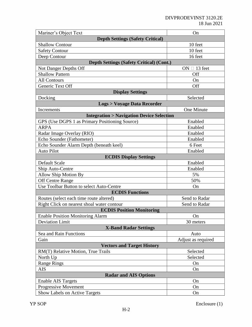
DIVPRODEVINST 3120.2E
18 Jun 2021
YP SOP Enclosure (1)
H-2
Mariner’s Object Text On
Depth Settings (Safety Critical)
Shallow Contour 10 feet
Safety Contour 10 feet
Deep Contour 16 feet
Depth Settings (Safety Critical) (Cont.)
Not Danger Depths Off ON 🡪 13 feet
Shallow Pattern Off
All Contours On
Generic Text Off Off
Display Settings
Docking Selected
Logs > Voyage Data Recorder
Increments One Minute
Integration > Navigation Device Selection
GPS (Use DGPS 1 as Primary Positioning Source) Enabled
ARPA Enabled
Radar Image Overlay (RIO) Enabled
Echo Sounder (Fathometer) Enabled
Echo Sounder Alarm Depth (beneath keel) 6 Feet
Auto Pilot Enabled
ECDIS Display Settings
Default Scale Enabled
Ship Auto-Centre Enabled
Allow Ship Motion By 5%
Off Centre Range 50%
Use Toolbar Button to select Auto-Centre On
ECDIS Functions
Routes (select each time route altered) Send to Radar
Right Click on nearest shoal water contour Send to Radar
ECDIS Position Monitoring
Enable Position Monitoring Alarm On
Deviation Limit 30 meters
X-Band Radar Settings
Sea and Rain Functions Auto
Gain Adjust as required
Vectors and Target History
RM(T) Relative Motion, True Trails Selected
North Up Selected
Range Rings On
AIS On
Radar and AIS Options
Enable AIS Targets On
Progressive Movement On
Show Labels on Active Targets On

DIVPRODEVINST 3120.2E
18 Jun 2021
YP SOP Enclosure (1)
H-3
Sleeping Targets (if not dangerous) On
Draw outline Hull Shape if possible On
Show AIS AToN and Base Stations On
Display only targets within range Limits set at 55 NM
No Lost Targets Outside of 10 NM
Dangerous AIS Target CPA 1.0 NM
Dangerous AIS Target TCPA 5 minutes
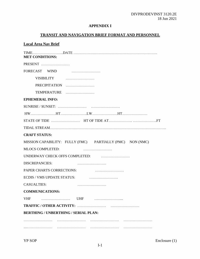
DIVPRODEVINST 3120.2E
18 Jun 2021
YP SOP Enclosure (1)
I-1
APPENDIX I
TRANSIT AND NAVIGATION BRIEF FORMAT AND PERSONNEL
Local Area Nav Brief
TIME……………………..DATE …………………………………………………………….
MET CONDITIONS:
PRESENT ……………………
FORECAST WIND ……………………
VISIBILITY ……………………
PRECIPITATION ……………………
TEMPERATURE ……………………
EPHEMERAL INFO:
SUNRISE / SUNSET: …………………… ……………………
HW…………………HT………………….LW…………………HT…………………
STATE OF TIDE …………………… HT OF TIDE AT……………….. ………………..FT
TIDAL STREAM…………………………………………………………………………………….
CRAFT STATUS:
MISSION CAPABILITY: FULLY (FMC) PARTIALLY (PMC) NON (NMC)
MLOCS COMPLETED: ……………………
UNDERWAY CHECK OFFS COMPLETED: ……………………
DISCREPANCIES: ……………………
PAPER CHARTS CORRECTIONS: ……………………
ECDIS / VMS UPDATE STATUS: ……………………
CASUALTIES: ……………………
COMMUNICATIONS:
VHF …………………… UHF …………………....
TRAFFIC / OTHER ACTIVITY: …………………… ……………………
BERTHING / UNBERTHING / SERIAL PLAN:
…………………… …………………… …………………… ……………………
....………………… …………………… …………………… ……………………
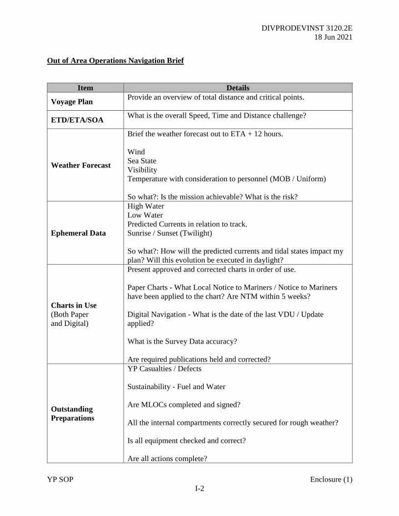
DIVPRODEVINST 3120.2E
18 Jun 2021
YP SOP Enclosure (1)
I-2
Out of Area Operations Navigation Brief
Item Details
Voyage Plan Provide an overview of total distance and critical points.
ETD/ETA/SOA What is the overall Speed, Time and Distance challenge?
Weather Forecast
Brief the weather forecast out to ETA + 12 hours.
Wind
Sea State
Visibility
Temperature with consideration to personnel (MOB / Uniform)
So what?: Is the mission achievable? What is the risk?
Ephemeral Data
High Water
Low Water
Predicted Currents in relation to track.
Sunrise / Sunset (Twilight)
So what?: How will the predicted currents and tidal states impact my
plan? Will this evolution be executed in daylight?
Charts in Use
(Both Paper
and Digital)
Present approved and corrected charts in order of use.
Paper Charts - What Local Notice to Mariners / Notice to Mariners
have been applied to the chart? Are NTM within 5 weeks?
Digital Navigation - What is the date of the last VDU / Update
applied?
What is the Survey Data accuracy?
Are required publications held and corrected?
Outstanding
Preparations
YP Casualties / Defects
Sustainability - Fuel and Water
Are MLOCs completed and signed?
All the internal compartments correctly secured for rough weather?
Is all equipment checked and correct?
Are all actions complete?
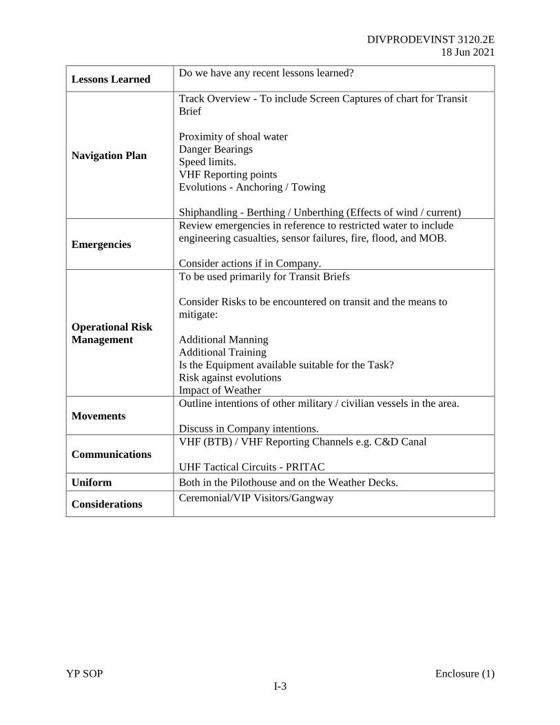
DIVPRODEVINST 3120.2E
18 Jun 2021
YP SOP Enclosure (1)
I-3
Lessons Learned Do we have any recent lessons learned?
Navigation Plan
Track Overview - To include Screen Captures of chart for Transit
Brief
Proximity of shoal water
Danger Bearings
Speed limits.
VHF Reporting points
Evolutions - Anchoring / Towing
Shiphandling - Berthing / Unberthing (Effects of wind / current)
Emergencies
Review emergencies in reference to restricted water to include
engineering casualties, sensor failures, fire, flood, and MOB.
Consider actions if in Company.
Operational Risk
Management
To be used primarily for Transit Briefs
Consider Risks to be encountered on transit and the means to
mitigate:
Additional Manning
Additional Training
Is the Equipment available suitable for the Task?
Risk against evolutions
Impact of Weather
Movements
Outline intentions of other military / civilian vessels in the area.
Discuss in Company intentions.
Communications
VHF (BTB) / VHF Reporting Channels e.g. C&D Canal
UHF Tactical Circuits - PRITAC
Uniform Both in the Pilothouse and on the Weather Decks.
Considerations Ceremonial/VIP Visitors/Gangway
DIVPRODEVINST 3120.2E
18 Jun 2021
YP SOP Enclosure (1)
I-4
Attendance Roster for the Navigation and Transit Briefs
Navigation Brief Attendance Register
(Attendance Required by all Personnel)
From/To
Date/Time/Venue
*PRODEV / SEANAV
*Officer in Tactical Command (If
assigned)
Officer in Charge (OIC)
Assistant OIC
Craftmaster (CM)
Engineer
MIDN Commanding Officer
MIDN Executive Officer
Officer of the Deck
Conning Officer
Assistant Navigator
Plotter
Radar Operator
Helmsman
Lee Helm
Bearing Book Recorder
Port Bearing Taker
Starboard Bearing Taker
Notes:
1. OTC and PRODEV / SEANAV attendance required for Transit Briefs only.
2. Luce Hall Planetarium to be booked through SEANAV Academics Officer in advance for
Transit Briefs.
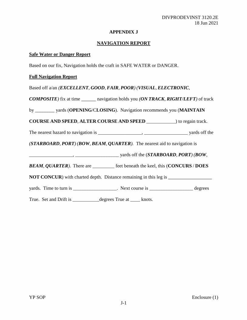
DIVPRODEVINST 3120.2E
18 Jun 2021
YP SOP Enclosure (1)
J-1
APPENDIX J
NAVIGATION REPORT
Safe Water or Danger Report
Based on our fix, Navigation holds the craft in SAFE WATER or DANGER.
Full Navigation Report
Based off a/an (EXCELLENT, GOOD, FAIR, POOR) (VISUAL, ELECTRONIC,
COMPOSITE) fix at time ______ navigation holds you (ON TRACK, RIGHT/LEFT) of track
by ________ yards (OPENING/CLOSING). Navigation recommends you (MAINTAIN
COURSE AND SPEED, ALTER COURSE AND SPEED ____________) to regain track.
The nearest hazard to navigation is __________________, __________________ yards off the
(STARBOARD, PORT) (BOW, BEAM, QUARTER). The nearest aid to navigation is
__________________, __________________ yards off the (STARBOARD, PORT) (BOW,
BEAM, QUARTER). There are _________ feet beneath the keel, this (CONCURS / DOES
NOT CONCUR) with charted depth. Distance remaining in this leg is __________________
yards. Time to turn is __________________. Next course is __________________ degrees
True. Set and Drift is ___________degrees True at ____ knots.
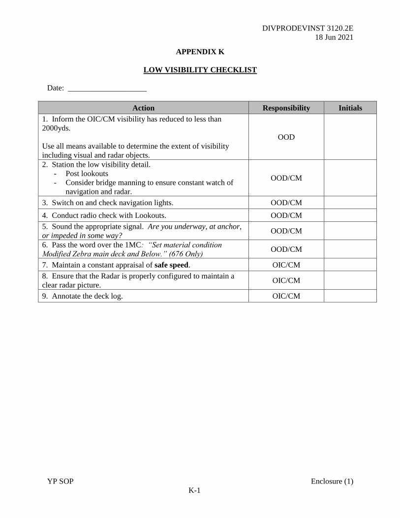
DIVPRODEVINST 3120.2E
18 Jun 2021
YP SOP Enclosure (1)
K-1
APPENDIX K
LOW VISIBILITY CHECKLIST
Date: ____________________
Action Responsibility Initials
1. Inform the OIC/CM visibility has reduced to less than
2000yds.
Use all means available to determine the extent of visibility
including visual and radar objects.
OOD
2. Station the low visibility detail.
- Post lookouts
- Consider bridge manning to ensure constant watch of
navigation and radar.
OOD/CM
3. Switch on and check navigation lights. OOD/CM
4. Conduct radio check with Lookouts. OOD/CM
5. Sound the appropriate signal. Are you underway, at anchor,
or impeded in some way? OOD/CM
6. Pass the word over the 1MC: “Set material condition
Modified Zebra main deck and Below.” (676 Only) OOD/CM
7. Maintain a constant appraisal of safe speed. OIC/CM
8. Ensure that the Radar is properly configured to maintain a
clear radar picture. OIC/CM
9. Annotate the deck log. OIC/CM
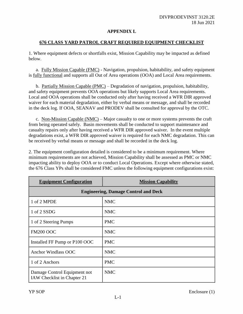
DIVPRODEVINST 3120.2E
18 Jun 2021
YP SOP Enclosure (1)
L-1
APPENDIX L
676 CLASS YARD PATROL CRAFT REQUIRED EQUIPMENT CHECKLIST
1. Where equipment defects or shortfalls exist, Mission Capability may be impacted as defined
below.
a. Fully Mission Capable (FMC) - Navigation, propulsion, habitability, and safety equipment
is fully functional and supports all Out of Area operations (OOA) and Local Area requirements.
b. Partially Mission Capable (PMC) – Degradation of navigation, propulsion, habitability,
and safety equipment prevents OOA operations but likely supports Local Area requirements.
Local and OOA operations shall be conducted only after having received a WFR DIR approved
waiver for each material degradation, either by verbal means or message, and shall be recorded
in the deck log. If OOA, SEANAV and PRODEV shall be consulted for approval by the OTC.
c. Non-Mission Capable (NMC) – Major casualty to one or more systems prevents the craft
from being operated safely. Basin movements shall be conducted to support maintenance and
casualty repairs only after having received a WFR DIR approved waiver. In the event multiple
degradations exist, a WFR DIR approved waiver is required for each NMC degradation. This can
be received by verbal means or message and shall be recorded in the deck log.
2. The equipment configuration detailed is considered to be a minimum requirement. Where
minimum requirements are not achieved, Mission Capability shall be assessed as PMC or NMC
impacting ability to deploy OOA or to conduct Local Operations. Except where otherwise stated,
the 676 Class YPs shall be considered FMC unless the following equipment configurations exist:
Equipment Configuration Mission Capability
Engineering, Damage Control and Deck
1 of 2 MPDE NMC
1 of 2 SSDG NMC
1 of 2 Steering Pumps PMC
FM200 OOC NMC
Installed FF Pump or P100 OOC PMC
Anchor Windlass OOC NMC
1 of 2 Anchors PMC
Damage Control Equipment not
IAW Checklist in Chapter 21
NMC
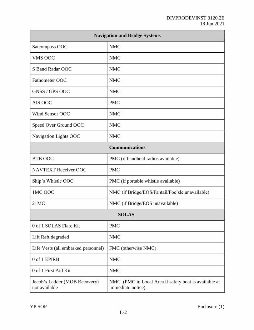
DIVPRODEVINST 3120.2E
18 Jun 2021
YP SOP Enclosure (1)
L-2
Navigation and Bridge Systems
Satcompass OOC NMC
VMS OOC NMC
S Band Radar OOC NMC
Fathometer OOC NMC
GNSS / GPS OOC NMC
AIS OOC PMC
Wind Sensor OOC NMC
Speed Over Ground OOC NMC
Navigation Lights OOC NMC
Communications
BTB OOC PMC (if handheld radios available)
NAVTEXT Receiver OOC PMC
Ship’s Whistle OOC PMC (if portable whistle available)
1MC OOC NMC (if Bridge/EOS/Fantail/Foc’sle unavailable)
21MC NMC (if Bridge/EOS unavailable)
SOLAS
0 of 1 SOLAS Flare Kit PMC
Lift Raft degraded NMC
Life Vests (all embarked personnel) FMC (otherwise NMC)
0 of 1 EPIRB NMC
0 of 1 First Aid Kit NMC
Jacob’s Ladder (MOB Recovery)
not available
NMC. (PMC in Local Area if safety boat is available at
immediate notice).
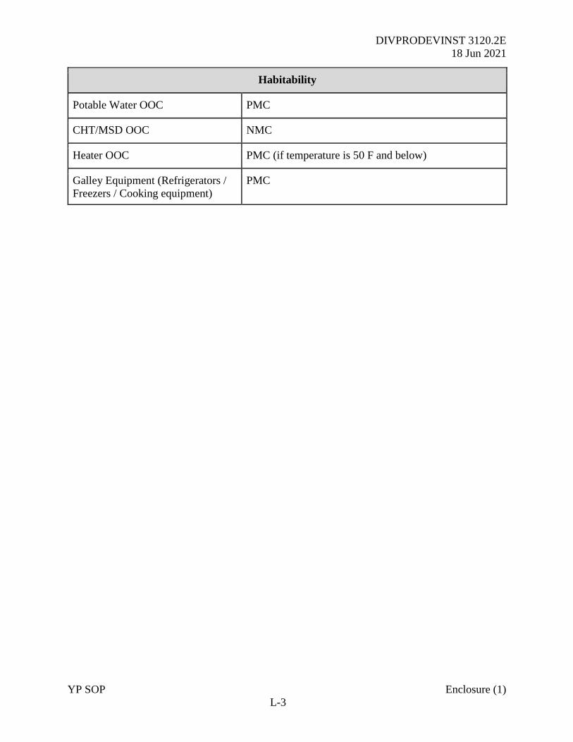
DIVPRODEVINST 3120.2E
18 Jun 2021
YP SOP Enclosure (1)
L-3
Habitability
Potable Water OOC PMC
CHT/MSD OOC NMC
Heater OOC PMC (if temperature is 50 F and below)
Galley Equipment (Refrigerators /
Freezers / Cooking equipment)
PMC
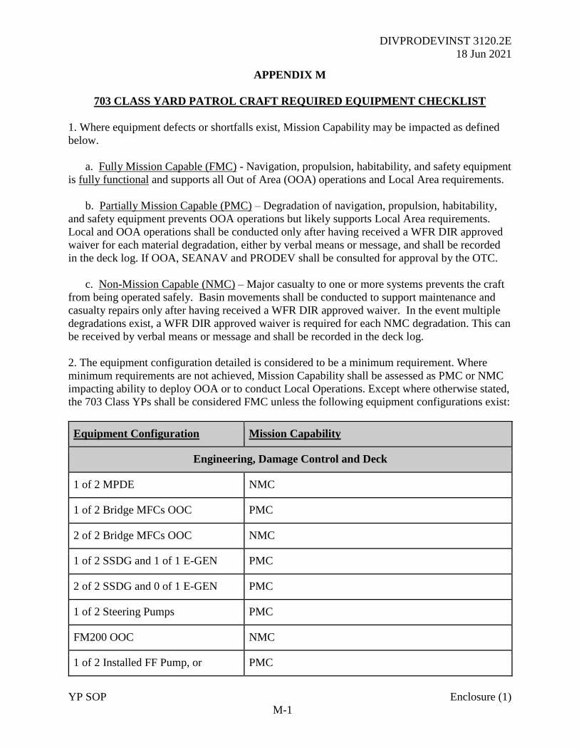
DIVPRODEVINST 3120.2E
18 Jun 2021
YP SOP Enclosure (1)
M-1
APPENDIX M
703 CLASS YARD PATROL CRAFT REQUIRED EQUIPMENT CHECKLIST
1. Where equipment defects or shortfalls exist, Mission Capability may be impacted as defined
below.
a. Fully Mission Capable (FMC) - Navigation, propulsion, habitability, and safety equipment
is fully functional and supports all Out of Area (OOA) operations and Local Area requirements.
b. Partially Mission Capable (PMC) – Degradation of navigation, propulsion, habitability,
and safety equipment prevents OOA operations but likely supports Local Area requirements.
Local and OOA operations shall be conducted only after having received a WFR DIR approved
waiver for each material degradation, either by verbal means or message, and shall be recorded
in the deck log. If OOA, SEANAV and PRODEV shall be consulted for approval by the OTC.
c. Non-Mission Capable (NMC) – Major casualty to one or more systems prevents the craft
from being operated safely. Basin movements shall be conducted to support maintenance and
casualty repairs only after having received a WFR DIR approved waiver. In the event multiple
degradations exist, a WFR DIR approved waiver is required for each NMC degradation. This can
be received by verbal means or message and shall be recorded in the deck log.
2. The equipment configuration detailed is considered to be a minimum requirement. Where
minimum requirements are not achieved, Mission Capability shall be assessed as PMC or NMC
impacting ability to deploy OOA or to conduct Local Operations. Except where otherwise stated,
the 703 Class YPs shall be considered FMC unless the following equipment configurations exist:
Equipment Configuration Mission Capability
Engineering, Damage Control and Deck
1 of 2 MPDE NMC
1 of 2 Bridge MFCs OOC PMC
2 of 2 Bridge MFCs OOC NMC
1 of 2 SSDG and 1 of 1 E-GEN PMC
2 of 2 SSDG and 0 of 1 E-GEN PMC
1 of 2 Steering Pumps PMC
FM200 OOC NMC
1 of 2 Installed FF Pump, or PMC
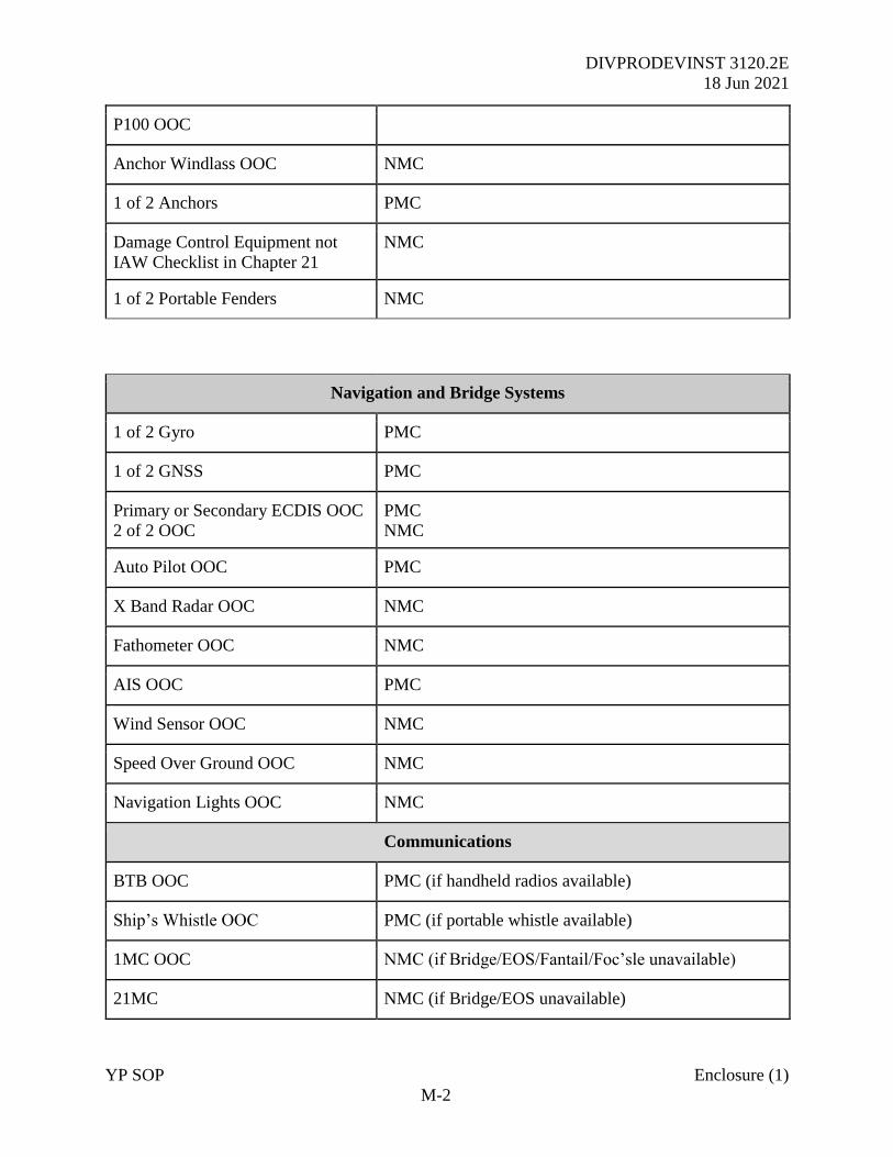
DIVPRODEVINST 3120.2E
18 Jun 2021
YP SOP Enclosure (1)
M-2
P100 OOC
Anchor Windlass OOC NMC
1 of 2 Anchors PMC
Damage Control Equipment not
IAW Checklist in Chapter 21
NMC
1 of 2 Portable Fenders NMC
Navigation and Bridge Systems
1 of 2 Gyro PMC
1 of 2 GNSS PMC
Primary or Secondary ECDIS OOC
2 of 2 OOC
PMC
NMC
Auto Pilot OOC PMC
X Band Radar OOC NMC
Fathometer OOC NMC
AIS OOC PMC
Wind Sensor OOC NMC
Speed Over Ground OOC NMC
Navigation Lights OOC NMC
Communications
BTB OOC PMC (if handheld radios available)
Ship’s Whistle OOC PMC (if portable whistle available)
1MC OOC NMC (if Bridge/EOS/Fantail/Foc’sle unavailable)
21MC NMC (if Bridge/EOS unavailable)
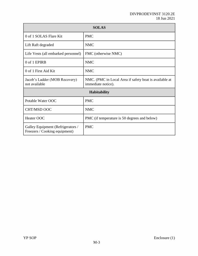
DIVPRODEVINST 3120.2E
18 Jun 2021
YP SOP Enclosure (1)
M-3
SOLAS
0 of 1 SOLAS Flare Kit PMC
Lift Raft degraded NMC
Life Vests (all embarked personnel) FMC (otherwise NMC)
0 of 1 EPIRB NMC
0 of 1 First Aid Kit NMC
Jacob’s Ladder (MOB Recovery)
not available
NMC. (PMC in Local Area if safety boat is available at
immediate notice).
Habitability
Potable Water OOC PMC
CHT/MSD OOC NMC
Heater OOC PMC (if temperature is 50 degrees and below)
Galley Equipment (Refrigerators /
Freezers / Cooking equipment)
PMC
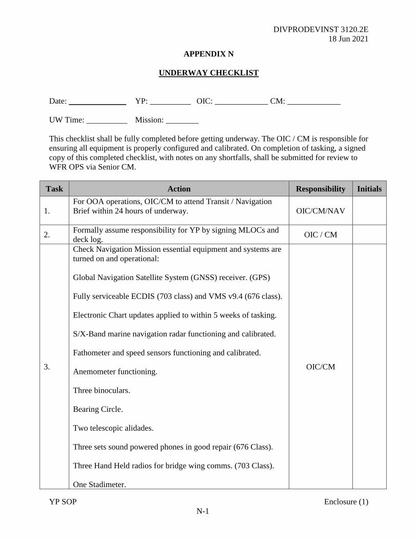
DIVPRODEVINST 3120.2E
18 Jun 2021
YP SOP Enclosure (1)
N-1
APPENDIX N
UNDERWAY CHECKLIST
Date: ______________ YP: __________ OIC: _____________ CM: _____________
UW Time: __________ Mission: ________
This checklist shall be fully completed before getting underway. The OIC / CM is responsible for
ensuring all equipment is properly configured and calibrated. On completion of tasking, a signed
copy of this completed checklist, with notes on any shortfalls, shall be submitted for review to
WFR OPS via Senior CM.
Task Action Responsibility Initials
1.
For OOA operations, OIC/CM to attend Transit / Navigation
Brief within 24 hours of underway.
OIC/CM/NAV
2. Formally assume responsibility for YP by signing MLOCs and
deck log. OIC / CM
3.
Check Navigation Mission essential equipment and systems are
turned on and operational:
Global Navigation Satellite System (GNSS) receiver. (GPS)
Fully serviceable ECDIS (703 class) and VMS v9.4 (676 class).
Electronic Chart updates applied to within 5 weeks of tasking.
S/X-Band marine navigation radar functioning and calibrated.
Fathometer and speed sensors functioning and calibrated.
Anemometer functioning.
Three binoculars.
Bearing Circle.
Two telescopic alidades.
Three sets sound powered phones in good repair (676 Class).
Three Hand Held radios for bridge wing comms. (703 Class).
One Stadimeter.
OIC/CM
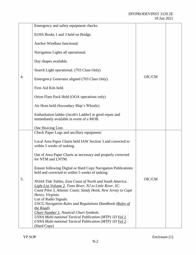
DIVPRODEVINST 3120.2E
18 Jun 2021
YP SOP Enclosure (1)
N-2
4.
Emergency and safety equipment checks:
EOSS Books 1 and 3 held on Bridge.
Anchor Windlass functional.
Navigation Lights all operational.
Day shapes available.
Search Light operational. (703 Class Only)
Emergency Generator aligned (703 Class Only).
First Aid Kits held.
Orion Flare Pack Held (OOA operations only)
Air Horn held (Secondary Ship’s Whistle).
Embarkation ladder (Jacob's Ladder) in good repair and
immediately available in event of a MOB.
One Heaving Line.
OIC/CM
5.
Check Paper Logs and ancillary equipment:
Local Area Paper Charts held IAW Section 3 and corrected to
within 5 weeks of tasking.
Out of Area Paper Charts as necessary and properly corrected
for NTM and LNTM.
Ensure following Digital or Hard Copy Navigation Publications
held and corrected to within 5 weeks of tasking:
NOAA Tide Tables, East Coast of North and South America.
Light List Volume 2, Toms River, NJ to Little River, SC.
Coast Pilot 3, Atlantic Coast; Sandy Hook, New Jersey to Cape
Henry, Virginia.
List of Radio Signals.
USCG Navigation Rules and Regulations Handbook (Rules of
the Road).
Chart Number 1, Nautical Chart Symbols.
USNA Multi-national Tactical Publication (MTP) 1D Vol 1.
USNA Multi-national Tactical Publication (MTP) 1D Vol 2.
(Hard Copy)
OIC/CM
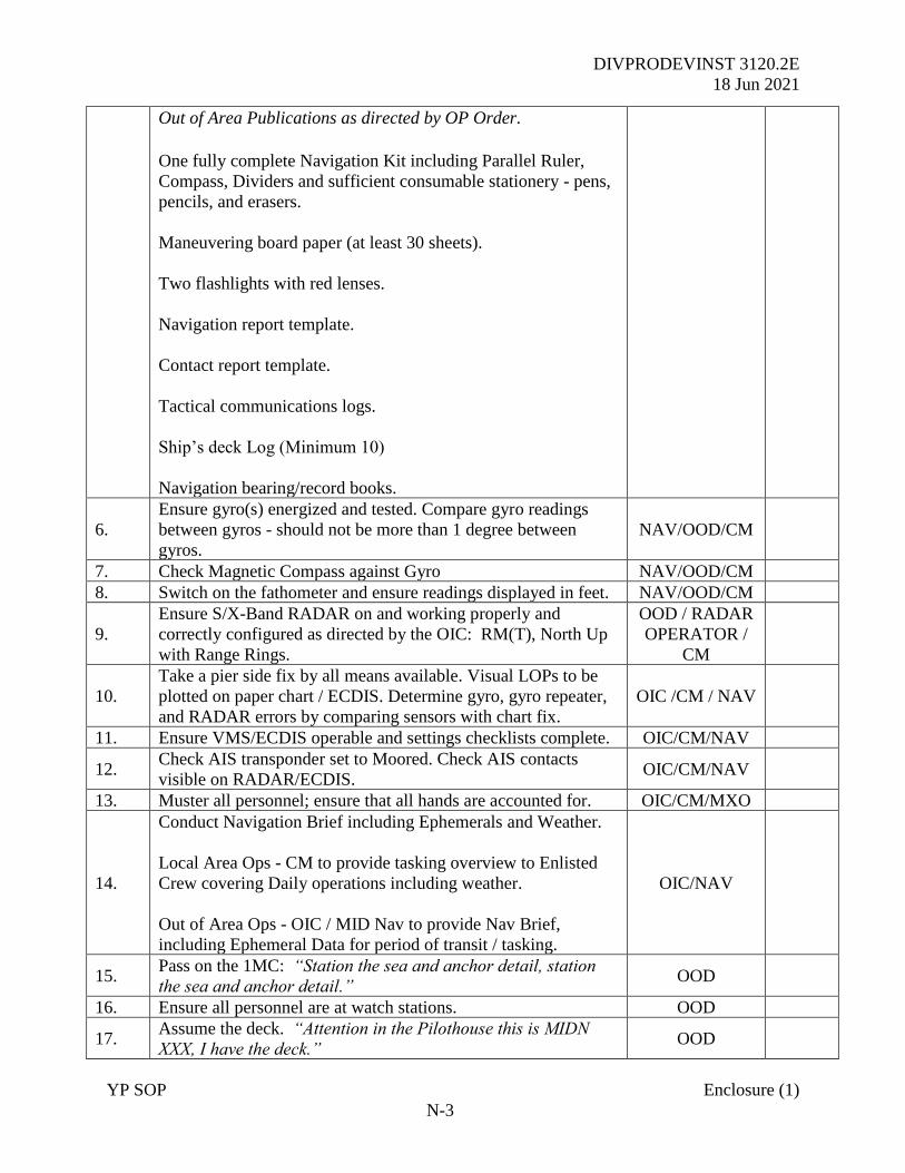
DIVPRODEVINST 3120.2E
18 Jun 2021
YP SOP Enclosure (1)
N-3
Out of Area Publications as directed by OP Order.
One fully complete Navigation Kit including Parallel Ruler,
Compass, Dividers and sufficient consumable stationery - pens,
pencils, and erasers.
Maneuvering board paper (at least 30 sheets).
Two flashlights with red lenses.
Navigation report template.
Contact report template.
Tactical communications logs.
Ship’s deck Log (Minimum 10)
Navigation bearing/record books.
6.
Ensure gyro(s) energized and tested. Compare gyro readings
between gyros - should not be more than 1 degree between
gyros.
NAV/OOD/CM
7. Check Magnetic Compass against Gyro NAV/OOD/CM
8. Switch on the fathometer and ensure readings displayed in feet. NAV/OOD/CM
9.
Ensure S/X-Band RADAR on and working properly and
correctly configured as directed by the OIC: RM(T), North Up
with Range Rings.
OOD / RADAR
OPERATOR /
CM
10.
Take a pier side fix by all means available. Visual LOPs to be
plotted on paper chart / ECDIS. Determine gyro, gyro repeater,
and RADAR errors by comparing sensors with chart fix.
OIC /CM / NAV
11. Ensure VMS/ECDIS operable and settings checklists complete. OIC/CM/NAV
12. Check AIS transponder set to Moored. Check AIS contacts
visible on RADAR/ECDIS. OIC/CM/NAV
13. Muster all personnel; ensure that all hands are accounted for. OIC/CM/MXO
14.
Conduct Navigation Brief including Ephemerals and Weather.
Local Area Ops - CM to provide tasking overview to Enlisted
Crew covering Daily operations including weather.
Out of Area Ops - OIC / MID Nav to provide Nav Brief,
including Ephemeral Data for period of transit / tasking.
OIC/NAV
15. Pass on the 1MC: “Station the sea and anchor detail, station
the sea and anchor detail.” OOD
16. Ensure all personnel are at watch stations. OOD
17. Assume the deck. “Attention in the Pilothouse this is MIDN
XXX, I have the deck.” OOD
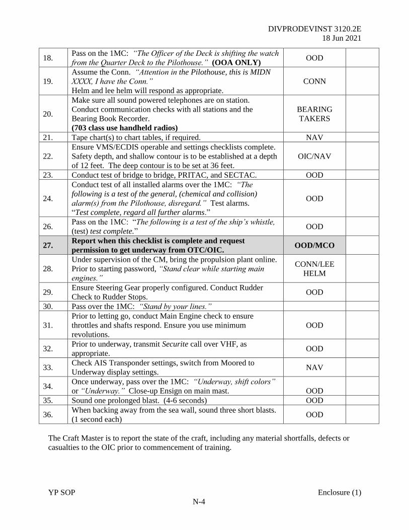
DIVPRODEVINST 3120.2E
18 Jun 2021
YP SOP Enclosure (1)
N-4
18. Pass on the 1MC: “The Officer of the Deck is shifting the watch
from the Quarter Deck to the Pilothouse.” (OOA ONLY) OOD
19.
Assume the Conn. “Attention in the Pilothouse, this is MIDN
XXXX, I have the Conn.”
Helm and lee helm will respond as appropriate.
CONN
20.
Make sure all sound powered telephones are on station.
Conduct communication checks with all stations and the
Bearing Book Recorder.
(703 class use handheld radios)
BEARING
TAKERS
21. Tape chart(s) to chart tables, if required. NAV
22.
Ensure VMS/ECDIS operable and settings checklists complete.
Safety depth, and shallow contour is to be established at a depth
of 12 feet. The deep contour is to be set at 36 feet.
OIC/NAV
23. Conduct test of bridge to bridge, PRITAC, and SECTAC. OOD
24.
Conduct test of all installed alarms over the 1MC: “The
following is a test of the general, (chemical and collision)
alarm(s) from the Pilothouse, disregard.” Test alarms.
“Test complete, regard all further alarms.”
OOD
26. Pass on the 1MC: “The following is a test of the ship’s whistle,
(test) test complete.” OOD
27. Report when this checklist is complete and request
permission to get underway from OTC/OIC. OOD/MCO
28.
Under supervision of the CM, bring the propulsion plant online.
Prior to starting password, “Stand clear while starting main
engines.”
CONN/LEE
HELM
29. Ensure Steering Gear properly configured. Conduct Rudder
Check to Rudder Stops. OOD
30. Pass over the 1MC: “Stand by your lines.”
31.
Prior to letting go, conduct Main Engine check to ensure
throttles and shafts respond. Ensure you use minimum
revolutions.
OOD
32. Prior to underway, transmit Securite call over VHF, as
appropriate. OOD
33. Check AIS Transponder settings, switch from Moored to
Underway display settings. NAV
34. Once underway, pass over the 1MC: “Underway, shift colors”
or “Underway.” Close-up Ensign on main mast.
OOD
35. Sound one prolonged blast. (4-6 seconds) OOD
36. When backing away from the sea wall, sound three short blasts.
(1 second each) OOD
The Craft Master is to report the state of the craft, including any material shortfalls, defects or
casualties to the OIC prior to commencement of training.
DIVPRODEVINST 3120.2E
18 Jun 2021
YP SOP Enclosure (1)
N-5
OIC Feedback
Craft Master Feedback
Senior CM / WFR Ops Feedback
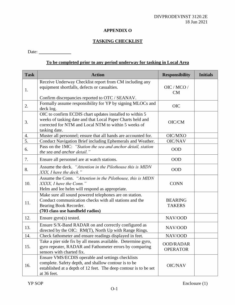
DIVPRODEVINST 3120.2E
18 Jun 2021
YP SOP Enclosure (1)
O-1
APPENDIX O
TASKING CHECKLIST
Date: ______________
To be completed prior to any period underway for tasking in Local Area
Task Action Responsibility Initials
1.
Receive Underway Checklist report from CM including any
equipment shortfalls, defects or casualties.
Confirm discrepancies reported to OTC / SEANAV.
OIC / MCO /
CM
2. Formally assume responsibility for YP by signing MLOCs and
deck log. OIC
3.
OIC to confirm ECDIS chart updates installed to within 5
weeks of tasking date and that Local Paper Charts held and
corrected for NTM and Local NTM to within 5 weeks of
tasking date.
OIC/CM
4. Muster all personnel; ensure that all hands are accounted for. OIC/MXO
5. Conduct Navigation Brief including Ephemerals and Weather. OIC/NAV
6. Pass on the 1MC: “Station the sea and anchor detail, station
the sea and anchor detail.” OOD
7. Ensure all personnel are at watch stations. OOD
8. Assume the deck. “Attention in the Pilothouse this is MIDN
XXX, I have the deck.” OOD
10.
Assume the Conn. “Attention in the Pilothouse, this is MIDN
XXXX, I have the Conn.”
Helm and lee helm will respond as appropriate.
CONN
11.
Make sure all sound powered telephones are on station.
Conduct communication checks with all stations and the
Bearing Book Recorder.
(703 class use handheld radios)
BEARING
TAKERS
12. Ensure gyro(s) tested. NAV/OOD
13. Ensure S/X-Band RADAR on and correctly configured as
directed by the OIC: RM(T), North Up with Range Rings. NAV/OOD
14. Check fathometer and ensure readings displayed in feet. NAV/OOD
15.
Take a pier side fix by all means available. Determine gyro,
gyro repeater, RADAR and Fathometer errors by comparing
sensors with charted fix.
OOD/RADAR
OPERATOR
16.
Ensure VMS/ECDIS operable and settings checklists
complete. Safety depth, and shallow contour is to be
established at a depth of 12 feet. The deep contour is to be set
at 36 feet.
OIC/NAV
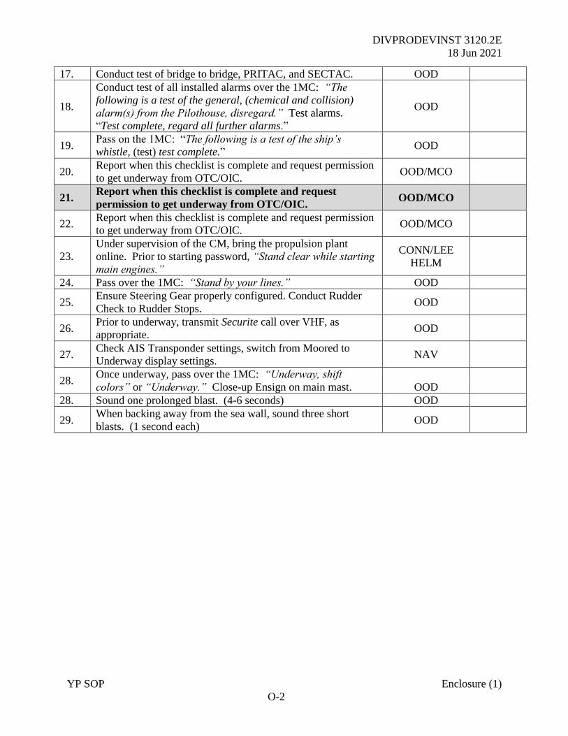
DIVPRODEVINST 3120.2E
18 Jun 2021
YP SOP Enclosure (1)
O-2
17. Conduct test of bridge to bridge, PRITAC, and SECTAC. OOD
18.
Conduct test of all installed alarms over the 1MC: “The
following is a test of the general, (chemical and collision)
alarm(s) from the Pilothouse, disregard.” Test alarms.
“Test complete, regard all further alarms.”
OOD
19. Pass on the 1MC: “The following is a test of the ship’s
whistle, (test) test complete.” OOD
20. Report when this checklist is complete and request permission
to get underway from OTC/OIC. OOD/MCO
21. Report when this checklist is complete and request
permission to get underway from OTC/OIC. OOD/MCO
22. Report when this checklist is complete and request permission
to get underway from OTC/OIC. OOD/MCO
23.
Under supervision of the CM, bring the propulsion plant
online. Prior to starting password, “Stand clear while starting
main engines.”
CONN/LEE
HELM
24. Pass over the 1MC: “Stand by your lines.” OOD
25. Ensure Steering Gear properly configured. Conduct Rudder
Check to Rudder Stops. OOD
26. Prior to underway, transmit Securite call over VHF, as
appropriate. OOD
27. Check AIS Transponder settings, switch from Moored to
Underway display settings. NAV
28. Once underway, pass over the 1MC: “Underway, shift
colors” or “Underway.” Close-up Ensign on main mast.
OOD
28. Sound one prolonged blast. (4-6 seconds) OOD
29. When backing away from the sea wall, sound three short
blasts. (1 second each) OOD
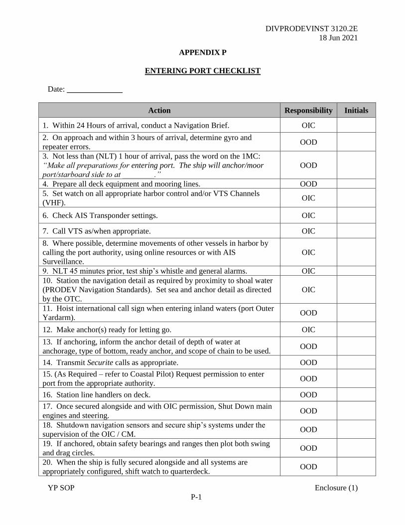
DIVPRODEVINST 3120.2E
18 Jun 2021
YP SOP Enclosure (1)
P-1
APPENDIX P
ENTERING PORT CHECKLIST
Date: ______________
Action Responsibility Initials
1. Within 24 Hours of arrival, conduct a Navigation Brief. OIC
2. On approach and within 3 hours of arrival, determine gyro and
repeater errors. OOD
3. Not less than (NLT) 1 hour of arrival, pass the word on the 1MC:
“Make all preparations for entering port. The ship will anchor/moor
port/starboard side to at ________.”
OOD
4. Prepare all deck equipment and mooring lines. OOD
5. Set watch on all appropriate harbor control and/or VTS Channels
(VHF). OIC
6. Check AIS Transponder settings. OIC
7. Call VTS as/when appropriate. OIC
8. Where possible, determine movements of other vessels in harbor by
calling the port authority, using online resources or with AIS
Surveillance.
OIC
9. NLT 45 minutes prior, test ship’s whistle and general alarms. OIC
10. Station the navigation detail as required by proximity to shoal water
(PRODEV Navigation Standards). Set sea and anchor detail as directed
by the OTC.
OIC
11. Hoist international call sign when entering inland waters (port Outer
Yardarm). OOD
12. Make anchor(s) ready for letting go. OIC
13. If anchoring, inform the anchor detail of depth of water at
anchorage, type of bottom, ready anchor, and scope of chain to be used. OOD
14. Transmit Securite calls as appropriate. OOD
15. (As Required – refer to Coastal Pilot) Request permission to enter
port from the appropriate authority. OOD
16. Station line handlers on deck. OOD
17. Once secured alongside and with OIC permission, Shut Down main
engines and steering. OOD
18. Shutdown navigation sensors and secure ship’s systems under the
supervision of the OIC / CM. OOD
19. If anchored, obtain safety bearings and ranges then plot both swing
and drag circles. OOD
20. When the ship is fully secured alongside and all systems are
appropriately configured, shift watch to quarterdeck. OOD
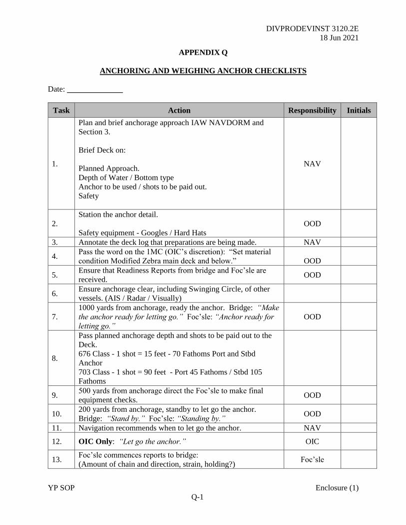
DIVPRODEVINST 3120.2E
18 Jun 2021
YP SOP Enclosure (1)
Q-1
APPENDIX Q
ANCHORING AND WEIGHING ANCHOR CHECKLISTS
Date: ______________
Task Action Responsibility Initials
1.
Plan and brief anchorage approach IAW NAVDORM and
Section 3.
Brief Deck on:
Planned Approach.
Depth of Water / Bottom type
Anchor to be used / shots to be paid out.
Safety
NAV
2.
Station the anchor detail.
Safety equipment - Googles / Hard Hats
OOD
3. Annotate the deck log that preparations are being made. NAV
4. Pass the word on the 1MC (OIC’s discretion): “Set material
condition Modified Zebra main deck and below.”
OOD
5. Ensure that Readiness Reports from bridge and Foc’sle are
received. OOD
6. Ensure anchorage clear, including Swinging Circle, of other
vessels. (AIS / Radar / Visually)
7.
1000 yards from anchorage, ready the anchor. Bridge: “Make
the anchor ready for letting go.” Foc’sle: “Anchor ready for
letting go.”
OOD
8.
Pass planned anchorage depth and shots to be paid out to the
Deck.
676 Class - 1 shot = 15 feet - 70 Fathoms Port and Stbd
Anchor
703 Class - 1 shot = 90 feet - Port 45 Fathoms / Stbd 105
Fathoms
9. 500 yards from anchorage direct the Foc’sle to make final
equipment checks. OOD
10. 200 yards from anchorage, standby to let go the anchor.
Bridge: “Stand by.” Foc’sle: “Standing by.” OOD
11. Navigation recommends when to let go the anchor. NAV
12. OIC Only: “Let go the anchor.” OIC
13. Foc’sle commences reports to bridge:
(Amount of chain and direction, strain, holding?) Foc’sle
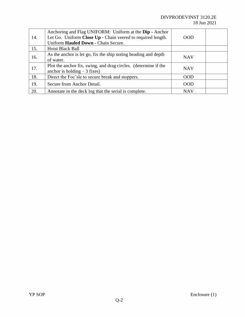
DIVPRODEVINST 3120.2E
18 Jun 2021
YP SOP Enclosure (1)
Q-2
14.
Anchoring and Flag UNIFORM: Uniform at the Dip - Anchor
Let Go. Uniform Close Up - Chain veered to required length.
Uniform Hauled Down - Chain Secure.
OOD
15. Hoist Black Ball
16. As the anchor is let go, fix the ship noting heading and depth
of water. NAV
17. Plot the anchor fix, swing, and drag circles. (determine if the
anchor is holding – 3 fixes) NAV
18. Direct the Foc’sle to secure break and stoppers. OOD
19. Secure from Anchor Detail. OOD
20. Annotate in the deck log that the serial is complete. NAV
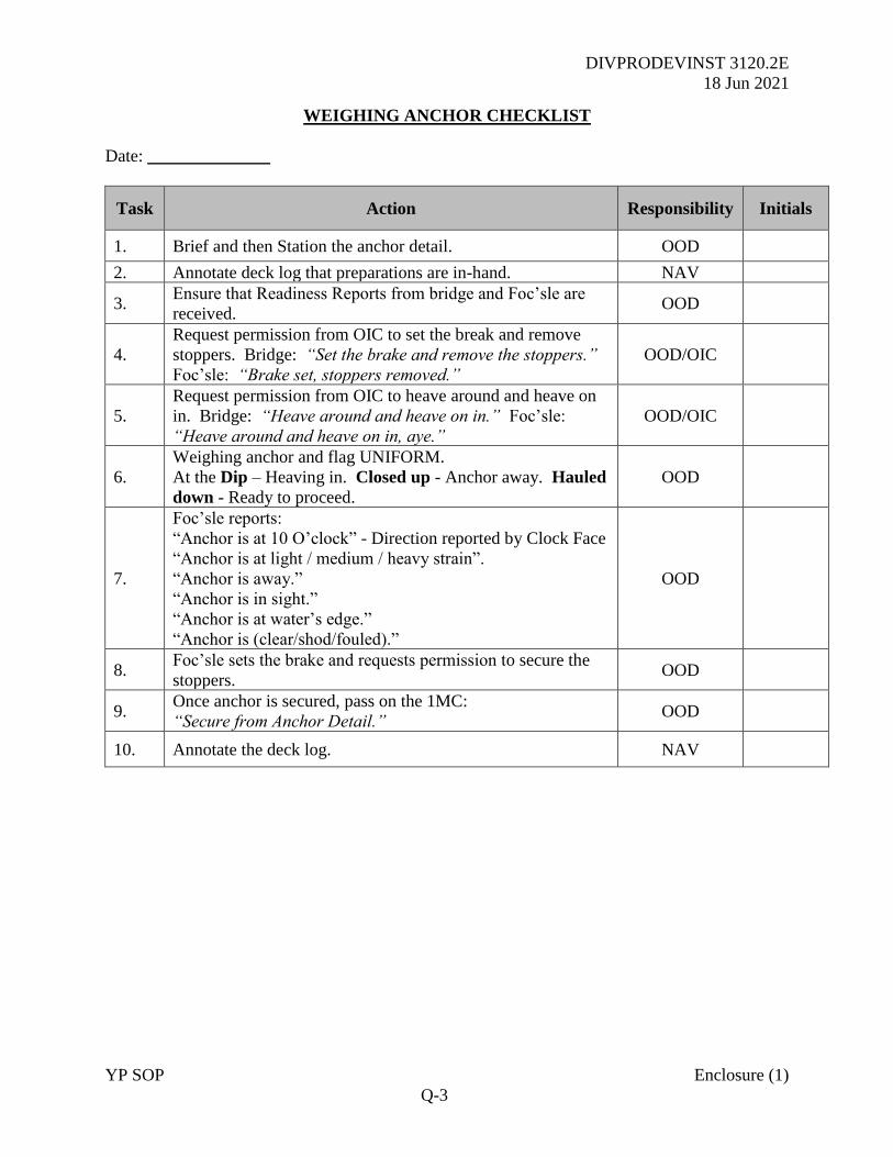
DIVPRODEVINST 3120.2E
18 Jun 2021
YP SOP Enclosure (1)
Q-3
WEIGHING ANCHOR CHECKLIST
Date: ______________
Task Action Responsibility Initials
1. Brief and then Station the anchor detail. OOD
2. Annotate deck log that preparations are in-hand. NAV
3. Ensure that Readiness Reports from bridge and Foc’sle are
received. OOD
4.
Request permission from OIC to set the break and remove
stoppers. Bridge: “Set the brake and remove the stoppers.”
Foc’sle: “Brake set, stoppers removed.”
OOD/OIC
5.
Request permission from OIC to heave around and heave on
in. Bridge: “Heave around and heave on in.” Foc’sle:
“Heave around and heave on in, aye.”
OOD/OIC
6.
Weighing anchor and flag UNIFORM.
At the Dip – Heaving in. Closed up - Anchor away. Hauled
down - Ready to proceed.
OOD
7.
Foc’sle reports:
“Anchor is at 10 O’clock” - Direction reported by Clock Face
“Anchor is at light / medium / heavy strain”.
“Anchor is away.”
“Anchor is in sight.”
“Anchor is at water’s edge.”
“Anchor is (clear/shod/fouled).”
OOD
8. Foc’sle sets the brake and requests permission to secure the
stoppers. OOD
9. Once anchor is secured, pass on the 1MC:
“Secure from Anchor Detail.” OOD
10. Annotate the deck log. NAV
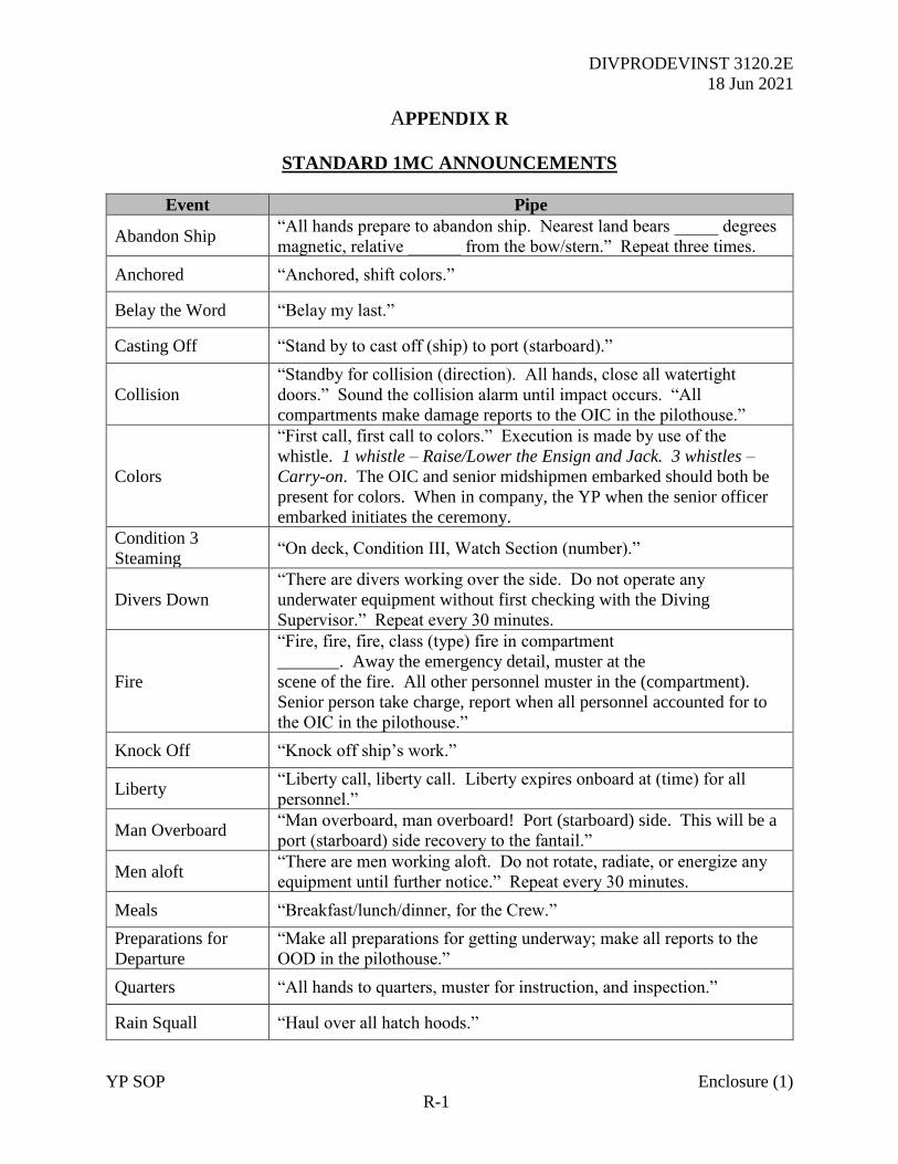
DIVPRODEVINST 3120.2E
18 Jun 2021
YP SOP Enclosure (1)
R-1
APPENDIX R
STANDARD 1MC ANNOUNCEMENTS
Event Pipe
Abandon Ship “All hands prepare to abandon ship. Nearest land bears _____ degrees
magnetic, relative ______ from the bow/stern.” Repeat three times.
Anchored “Anchored, shift colors.”
Belay the Word “Belay my last.”
Casting Off “Stand by to cast off (ship) to port (starboard).”
Collision
“Standby for collision (direction). All hands, close all watertight
doors.” Sound the collision alarm until impact occurs. “All
compartments make damage reports to the OIC in the pilothouse.”
Colors
“First call, first call to colors.” Execution is made by use of the
whistle. 1 whistle – Raise/Lower the Ensign and Jack. 3 whistles –
Carry-on. The OIC and senior midshipmen embarked should both be
present for colors. When in company, the YP when the senior officer
embarked initiates the ceremony.
Condition 3
Steaming “On deck, Condition III, Watch Section (number).”
Divers Down
“There are divers working over the side. Do not operate any
underwater equipment without first checking with the Diving
Supervisor.” Repeat every 30 minutes.
Fire
“Fire, fire, fire, class (type) fire in compartment
_______. Away the emergency detail, muster at the
scene of the fire. All other personnel muster in the (compartment).
Senior person take charge, report when all personnel accounted for to
the OIC in the pilothouse.”
Knock Off “Knock off ship’s work.”
Liberty “Liberty call, liberty call. Liberty expires onboard at (time) for all
personnel.”
Man Overboard “Man overboard, man overboard! Port (starboard) side. This will be a
port (starboard) side recovery to the fantail.”
Men aloft “There are men working aloft. Do not rotate, radiate, or energize any
equipment until further notice.” Repeat every 30 minutes.
Meals “Breakfast/lunch/dinner, for the Crew.”
Preparations for
Departure
“Make all preparations for getting underway; make all reports to the
OOD in the pilothouse.”
Quarters “All hands to quarters, muster for instruction, and inspection.”
Rain Squall “Haul over all hatch hoods.”
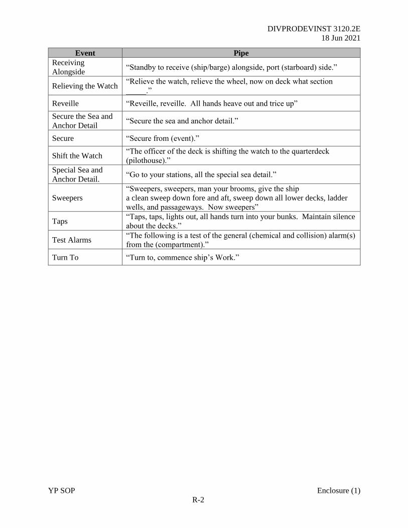
DIVPRODEVINST 3120.2E
18 Jun 2021
YP SOP Enclosure (1)
R-2
Event Pipe
Receiving
Alongside “Standby to receive (ship/barge) alongside, port (starboard) side.”
Relieving the Watch “Relieve the watch, relieve the wheel, now on deck what section
_____.”
Reveille “Reveille, reveille. All hands heave out and trice up”
Secure the Sea and
Anchor Detail “Secure the sea and anchor detail.”
Secure “Secure from (event).”
Shift the Watch “The officer of the deck is shifting the watch to the quarterdeck
(pilothouse).”
Special Sea and
Anchor Detail. “Go to your stations, all the special sea detail.”
Sweepers
“Sweepers, sweepers, man your brooms, give the ship
a clean sweep down fore and aft, sweep down all lower decks, ladder
wells, and passageways. Now sweepers”
Taps “Taps, taps, lights out, all hands turn into your bunks. Maintain silence
about the decks.”
Test Alarms “The following is a test of the general (chemical and collision) alarm(s)
from the (compartment).”
Turn To “Turn to, commence ship’s Work.”
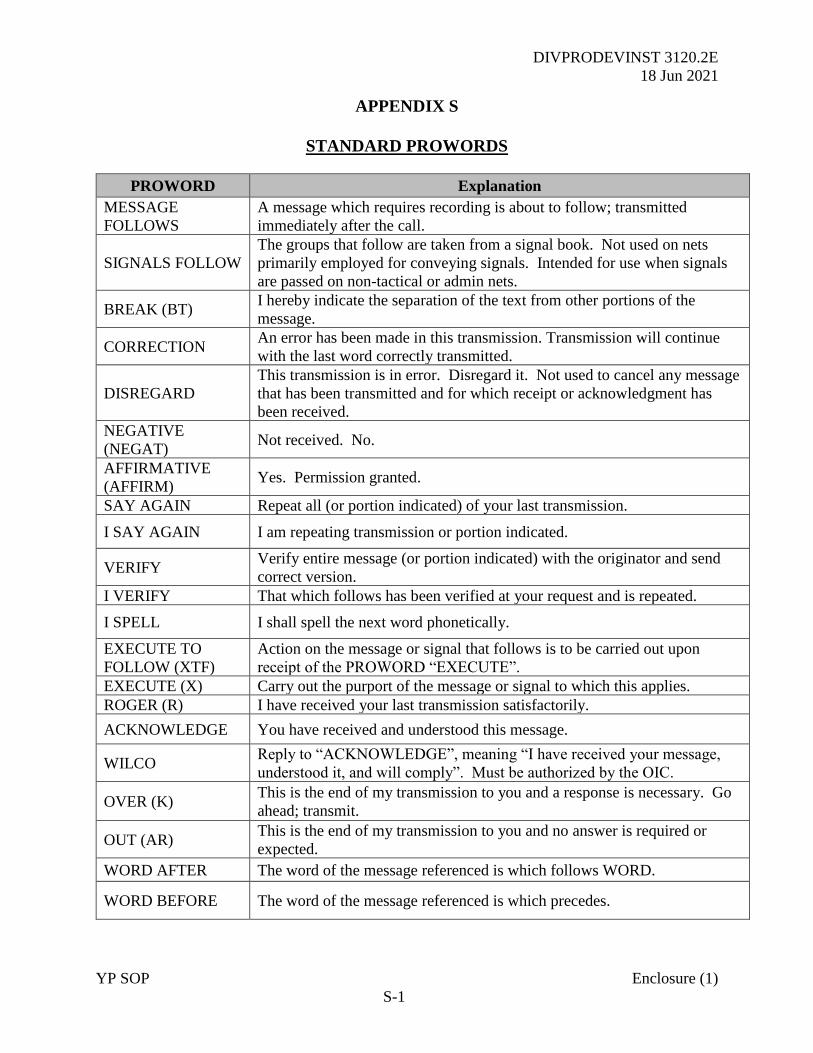
DIVPRODEVINST 3120.2E
18 Jun 2021
YP SOP Enclosure (1)
S-1
APPENDIX S
STANDARD PROWORDS
PROWORD Explanation
MESSAGE
FOLLOWS
A message which requires recording is about to follow; transmitted
immediately after the call.
SIGNALS FOLLOW
The groups that follow are taken from a signal book. Not used on nets
primarily employed for conveying signals. Intended for use when signals
are passed on non-tactical or admin nets.
BREAK (BT) I hereby indicate the separation of the text from other portions of the
message.
CORRECTION An error has been made in this transmission. Transmission will continue
with the last word correctly transmitted.
DISREGARD
This transmission is in error. Disregard it. Not used to cancel any message
that has been transmitted and for which receipt or acknowledgment has
been received.
NEGATIVE
(NEGAT) Not received. No.
AFFIRMATIVE
(AFFIRM) Yes. Permission granted.
SAY AGAIN Repeat all (or portion indicated) of your last transmission.
I SAY AGAIN I am repeating transmission or portion indicated.
VERIFY Verify entire message (or portion indicated) with the originator and send
correct version.
I VERIFY That which follows has been verified at your request and is repeated.
I SPELL I shall spell the next word phonetically.
EXECUTE TO
FOLLOW (XTF)
Action on the message or signal that follows is to be carried out upon
receipt of the PROWORD “EXECUTE”.
EXECUTE (X) Carry out the purport of the message or signal to which this applies.
ROGER (R) I have received your last transmission satisfactorily.
ACKNOWLEDGE You have received and understood this message.
WILCO Reply to “ACKNOWLEDGE”, meaning “I have received your message,
understood it, and will comply”. Must be authorized by the OIC.
OVER (K) This is the end of my transmission to you and a response is necessary. Go
ahead; transmit.
OUT (AR) This is the end of my transmission to you and no answer is required or
expected.
WORD AFTER The word of the message referenced is which follows WORD.
WORD BEFORE The word of the message referenced is which precedes.
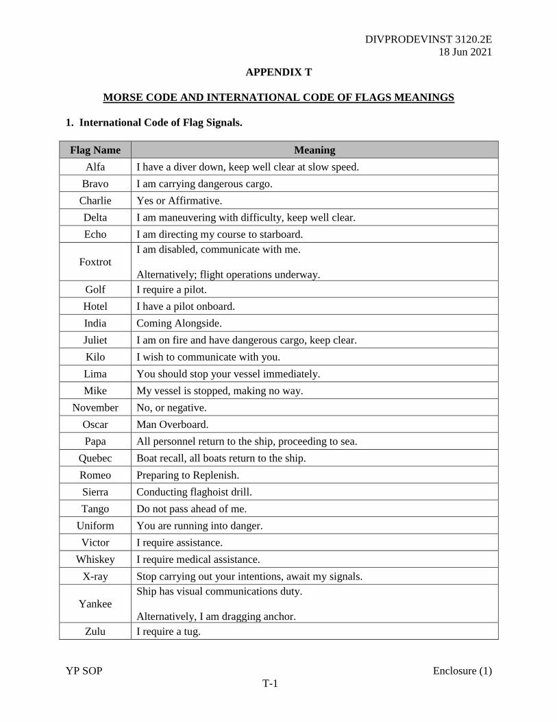
DIVPRODEVINST 3120.2E
18 Jun 2021
YP SOP Enclosure (1)
T-1
APPENDIX T
MORSE CODE AND INTERNATIONAL CODE OF FLAGS MEANINGS
1. International Code of Flag Signals.
Flag Name Meaning
Alfa I have a diver down, keep well clear at slow speed.
Bravo I am carrying dangerous cargo.
Charlie Yes or Affirmative.
Delta I am maneuvering with difficulty, keep well clear.
Echo I am directing my course to starboard.
Foxtrot
I am disabled, communicate with me.
Alternatively; flight operations underway.
Golf I require a pilot.
Hotel I have a pilot onboard.
India Coming Alongside.
Juliet I am on fire and have dangerous cargo, keep clear.
Kilo I wish to communicate with you.
Lima You should stop your vessel immediately.
Mike My vessel is stopped, making no way.
November No, or negative.
Oscar Man Overboard.
Papa All personnel return to the ship, proceeding to sea.
Quebec Boat recall, all boats return to the ship.
Romeo Preparing to Replenish.
Sierra Conducting flaghoist drill.
Tango Do not pass ahead of me.
Uniform You are running into danger.
Victor I require assistance.
Whiskey I require medical assistance.
X-ray Stop carrying out your intentions, await my signals.
Yankee
Ship has visual communications duty.
Alternatively, I am dragging anchor.
Zulu I require a tug.
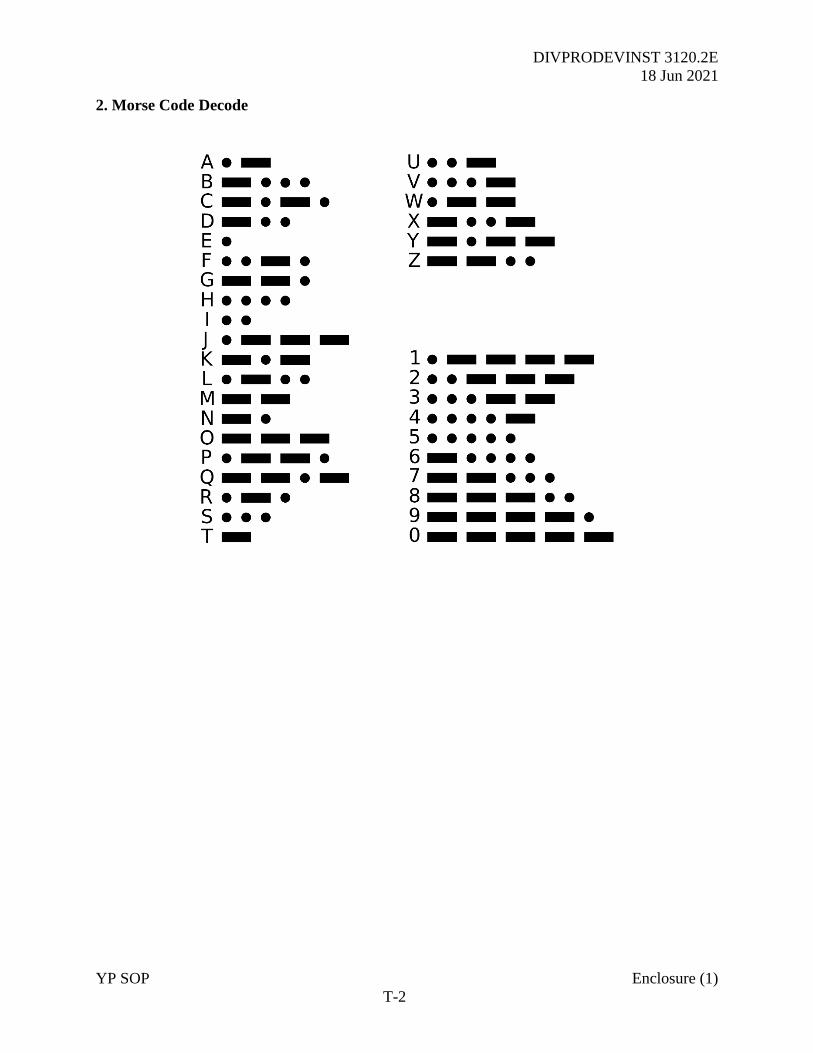
DIVPRODEVINST 3120.2E
18 Jun 2021
YP SOP Enclosure (1)
T-2
2. Morse Code Decode
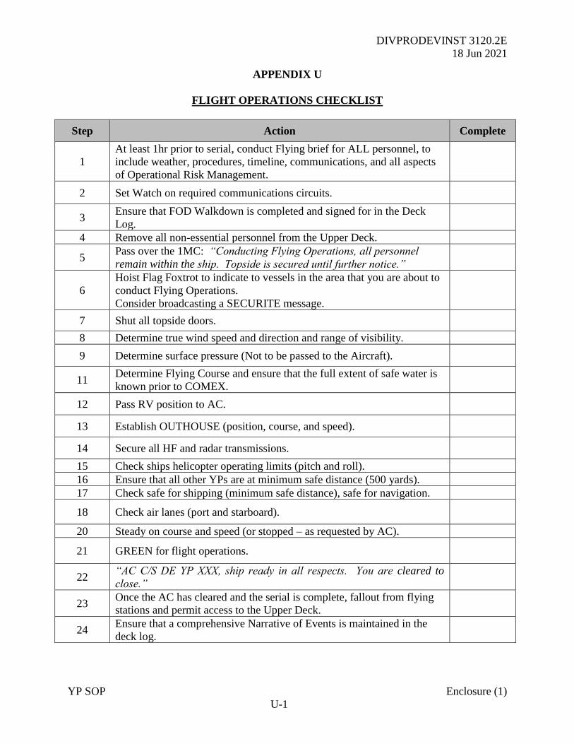
DIVPRODEVINST 3120.2E
18 Jun 2021
YP SOP Enclosure (1)
U-1
APPENDIX U
FLIGHT OPERATIONS CHECKLIST
Step Action Complete
1
At least 1hr prior to serial, conduct Flying brief for ALL personnel, to
include weather, procedures, timeline, communications, and all aspects
of Operational Risk Management.
2 Set Watch on required communications circuits.
3 Ensure that FOD Walkdown is completed and signed for in the Deck
Log.
4 Remove all non-essential personnel from the Upper Deck.
5 Pass over the 1MC: “Conducting Flying Operations, all personnel
remain within the ship. Topside is secured until further notice.”
6
Hoist Flag Foxtrot to indicate to vessels in the area that you are about to
conduct Flying Operations.
Consider broadcasting a SECURITE message.
7 Shut all topside doors.
8 Determine true wind speed and direction and range of visibility.
9 Determine surface pressure (Not to be passed to the Aircraft).
11 Determine Flying Course and ensure that the full extent of safe water is
known prior to COMEX.
12 Pass RV position to AC.
13 Establish OUTHOUSE (position, course, and speed).
14 Secure all HF and radar transmissions.
15 Check ships helicopter operating limits (pitch and roll).
16 Ensure that all other YPs are at minimum safe distance (500 yards).
17 Check safe for shipping (minimum safe distance), safe for navigation.
18 Check air lanes (port and starboard).
20 Steady on course and speed (or stopped – as requested by AC).
21 GREEN for flight operations.
22 “AC C/S DE YP XXX, ship ready in all respects. You are cleared to
close.”
23 Once the AC has cleared and the serial is complete, fallout from flying
stations and permit access to the Upper Deck.
24 Ensure that a comprehensive Narrative of Events is maintained in the
deck log.
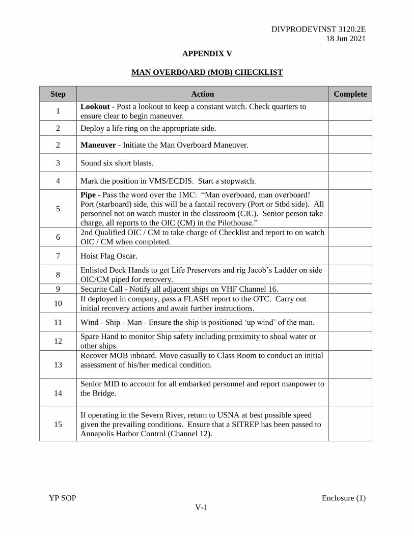
DIVPRODEVINST 3120.2E
18 Jun 2021
YP SOP Enclosure (1)
V-1
APPENDIX V
MAN OVERBOARD (MOB) CHECKLIST
Step Action Complete
1 Lookout - Post a lookout to keep a constant watch. Check quarters to
ensure clear to begin maneuver.
2 Deploy a life ring on the appropriate side.
2 Maneuver - Initiate the Man Overboard Maneuver.
3 Sound six short blasts.
4 Mark the position in VMS/ECDIS. Start a stopwatch.
5
Pipe - Pass the word over the 1MC: “Man overboard, man overboard!
Port (starboard) side, this will be a fantail recovery (Port or Stbd side). All
personnel not on watch muster in the classroom (CIC). Senior person take
charge, all reports to the OIC (CM) in the Pilothouse.”
6 2nd Qualified OIC / CM to take charge of Checklist and report to on watch
OIC / CM when completed.
7 Hoist Flag Oscar.
8 Enlisted Deck Hands to get Life Preservers and rig Jacob’s Ladder on side
OIC/CM piped for recovery.
9 Securite Call - Notify all adjacent ships on VHF Channel 16.
10 If deployed in company, pass a FLASH report to the OTC. Carry out
initial recovery actions and await further instructions.
11 Wind - Ship - Man - Ensure the ship is positioned ‘up wind’ of the man.
12 Spare Hand to monitor Ship safety including proximity to shoal water or
other ships.
13
Recover MOB inboard. Move casually to Class Room to conduct an initial
assessment of his/her medical condition.
14
Senior MID to account for all embarked personnel and report manpower to
the Bridge.
15
If operating in the Severn River, return to USNA at best possible speed
given the prevailing conditions. Ensure that a SITREP has been passed to
Annapolis Harbor Control (Channel 12).

DIVPRODEVINST 3120.2E
18 Jun 2021
YP SOP Enclosure (1)
W-1
APPENDIX W
FIRE FIGHTING CHECKLIST
Step Action Complete
1
On discovering any fire, pass the word over the 1MC:
“Fire, Fire, Fire! Class (A/B/C) fire in (compartment), (location
marking). Set mechanical and electrical isolation in (compartment). All
midshipmen muster in (compartment – clear of incident). Section Leader
take charge and account for all personnel. Pass all reports to the OIC on
the bridge.”
2 If in company, pass a FLASH report to the OTC by any means.
3 Inform the nearest shore authority. (Either Annapolis Harbor Control or
U.S. Coast Guard Sector)
4
OIC takes the Deck and maneuvers the craft towards the nearest port or
jetty. An assessment of the implications of system isolations must be
made immediately. If necessary, stop the YP.
5 CM will direct the firefighting effort and account for all enlisted personnel,
maintaining constant communications with the OIC on the bridge.
6
The YP Engineer is to take all required controlling actions to isolate
the compartment and fight the fire. Any personnel entering a smoke-
filled compartment must be tethered to a lifeline.
7 Report to the bridge once all isolations have been made.
8 All YP crewmembers are to prepare the necessary firefighting equipment
as directed by the Engineer.
9
Once all preparations are complete and a minimum of two crewmembers
are dressed in PPE and ready in all respects – request permission of the
OIC/CM to enter the compartment and fight the fire.
10 Report once the fire has been extinguished or when personnel are beaten
back.
11 As directed – initiate fixed firefighting systems.
12 Post a fire sentry.
13 Determine a smoke clearance plan.
14 Conduct damage assessment of the compartment and essential equipment.
15 Maintain a continuous assessment of stability.
16 So far as possible, re-commission essential equipment.
17 Pass a FIRE REPORT to USNA by any means.
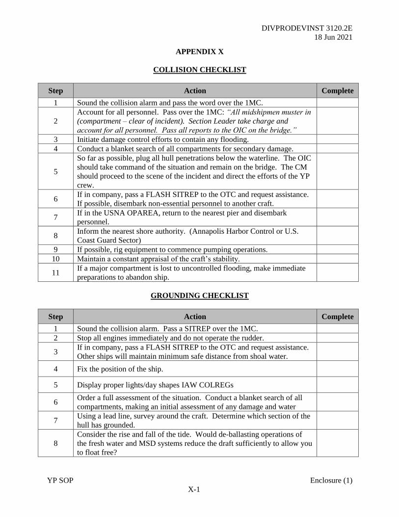
DIVPRODEVINST 3120.2E
18 Jun 2021
YP SOP Enclosure (1)
X-1
APPENDIX X
COLLISION CHECKLIST
Step Action Complete
1 Sound the collision alarm and pass the word over the 1MC.
2
Account for all personnel. Pass over the 1MC: “All midshipmen muster in
(compartment – clear of incident). Section Leader take charge and
account for all personnel. Pass all reports to the OIC on the bridge.”
3 Initiate damage control efforts to contain any flooding.
4 Conduct a blanket search of all compartments for secondary damage.
5
So far as possible, plug all hull penetrations below the waterline. The OIC
should take command of the situation and remain on the bridge. The CM
should proceed to the scene of the incident and direct the efforts of the YP
crew.
6 If in company, pass a FLASH SITREP to the OTC and request assistance.
If possible, disembark non-essential personnel to another craft.
7 If in the USNA OPAREA, return to the nearest pier and disembark
personnel.
8 Inform the nearest shore authority. (Annapolis Harbor Control or U.S.
Coast Guard Sector)
9 If possible, rig equipment to commence pumping operations.
10 Maintain a constant appraisal of the craft’s stability.
11 If a major compartment is lost to uncontrolled flooding, make immediate
preparations to abandon ship.
GROUNDING CHECKLIST
Step Action Complete
1 Sound the collision alarm. Pass a SITREP over the 1MC.
2 Stop all engines immediately and do not operate the rudder.
3 If in company, pass a FLASH SITREP to the OTC and request assistance.
Other ships will maintain minimum safe distance from shoal water.
4 Fix the position of the ship.
5 Display proper lights/day shapes IAW COLREGs
6 Order a full assessment of the situation. Conduct a blanket search of all
compartments, making an initial assessment of any damage and water
7 Using a lead line, survey around the craft. Determine which section of the
hull has grounded.
8
Consider the rise and fall of the tide. Would de-ballasting operations of
the fresh water and MSD systems reduce the draft sufficiently to allow you
to float free?
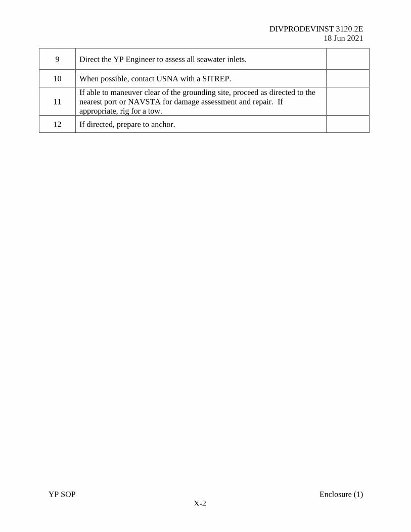
DIVPRODEVINST 3120.2E
18 Jun 2021
YP SOP Enclosure (1)
X-2
9 Direct the YP Engineer to assess all seawater inlets.
10 When possible, contact USNA with a SITREP.
11
If able to maneuver clear of the grounding site, proceed as directed to the
nearest port or NAVSTA for damage assessment and repair. If
appropriate, rig for a tow.
12 If directed, prepare to anchor.
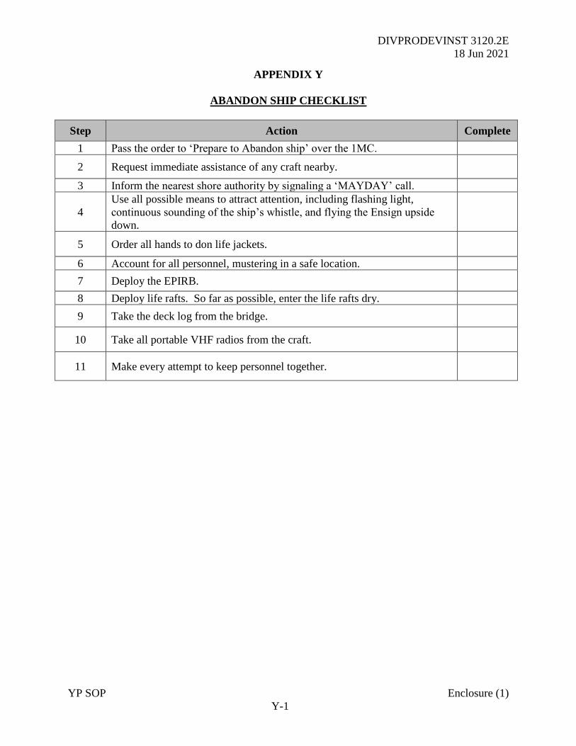
DIVPRODEVINST 3120.2E
18 Jun 2021
YP SOP Enclosure (1)
Y-1
APPENDIX Y
ABANDON SHIP CHECKLIST
Step Action Complete
1 Pass the order to ‘Prepare to Abandon ship’ over the 1MC.
2 Request immediate assistance of any craft nearby.
3 Inform the nearest shore authority by signaling a ‘MAYDAY’ call.
4
Use all possible means to attract attention, including flashing light,
continuous sounding of the ship’s whistle, and flying the Ensign upside
down.
5 Order all hands to don life jackets.
6 Account for all personnel, mustering in a safe location.
7 Deploy the EPIRB.
8 Deploy life rafts. So far as possible, enter the life rafts dry.
9 Take the deck log from the bridge.
10 Take all portable VHF radios from the craft.
11 Make every attempt to keep personnel together.
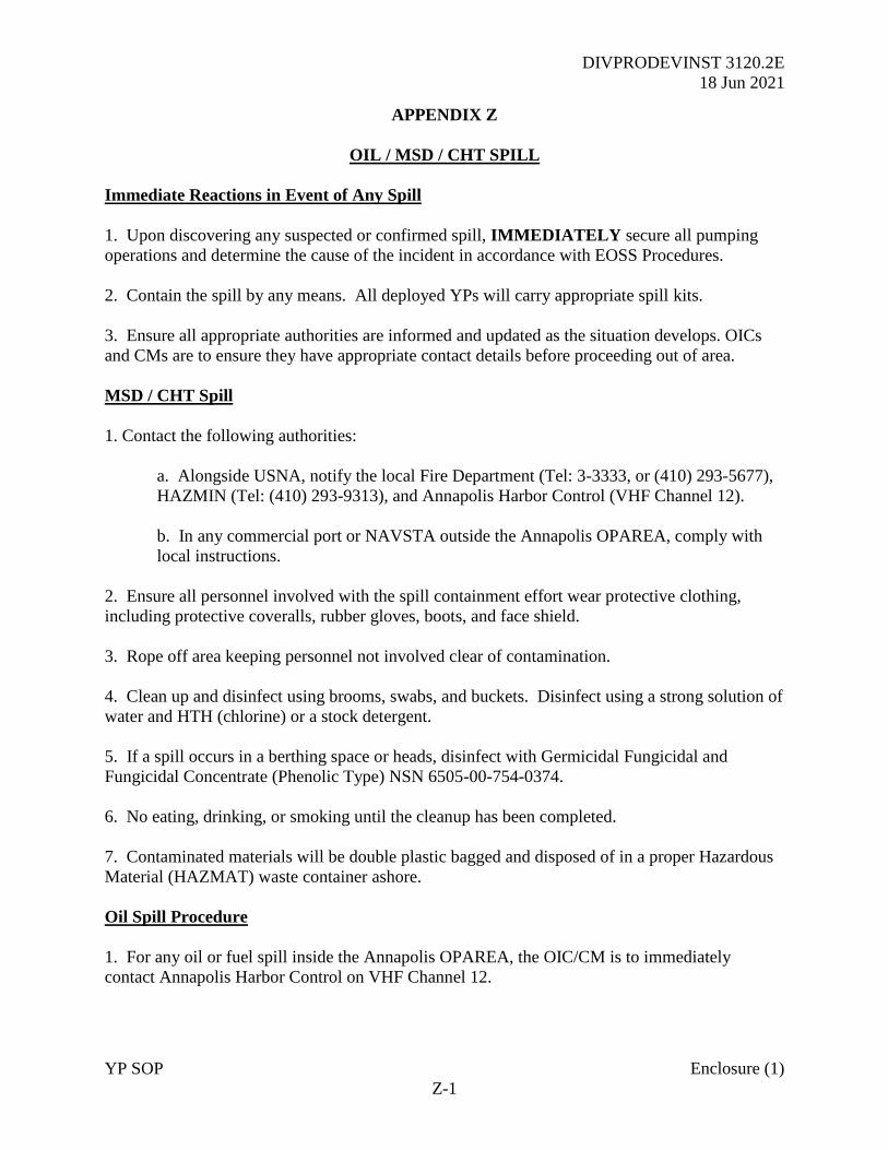
DIVPRODEVINST 3120.2E
18 Jun 2021
YP SOP Enclosure (1)
Z-1
APPENDIX Z
OIL / MSD / CHT SPILL
Immediate Reactions in Event of Any Spill
1. Upon discovering any suspected or confirmed spill, IMMEDIATELY secure all pumping
operations and determine the cause of the incident in accordance with EOSS Procedures.
2. Contain the spill by any means. All deployed YPs will carry appropriate spill kits.
3. Ensure all appropriate authorities are informed and updated as the situation develops. OICs
and CMs are to ensure they have appropriate contact details before proceeding out of area.
MSD / CHT Spill
1. Contact the following authorities:
a. Alongside USNA, notify the local Fire Department (Tel: 3-3333, or (410) 293-5677),
HAZMIN (Tel: (410) 293-9313), and Annapolis Harbor Control (VHF Channel 12).
b. In any commercial port or NAVSTA outside the Annapolis OPAREA, comply with
local instructions.
2. Ensure all personnel involved with the spill containment effort wear protective clothing,
including protective coveralls, rubber gloves, boots, and face shield.
3. Rope off area keeping personnel not involved clear of contamination.
4. Clean up and disinfect using brooms, swabs, and buckets. Disinfect using a strong solution of
water and HTH (chlorine) or a stock detergent.
5. If a spill occurs in a berthing space or heads, disinfect with Germicidal Fungicidal and
Fungicidal Concentrate (Phenolic Type) NSN 6505-00-754-0374.
6. No eating, drinking, or smoking until the cleanup has been completed.
7. Contaminated materials will be double plastic bagged and disposed of in a proper Hazardous
Material (HAZMAT) waste container ashore.
Oil Spill Procedure
1. For any oil or fuel spill inside the Annapolis OPAREA, the OIC/CM is to immediately
contact Annapolis Harbor Control on VHF Channel 12.
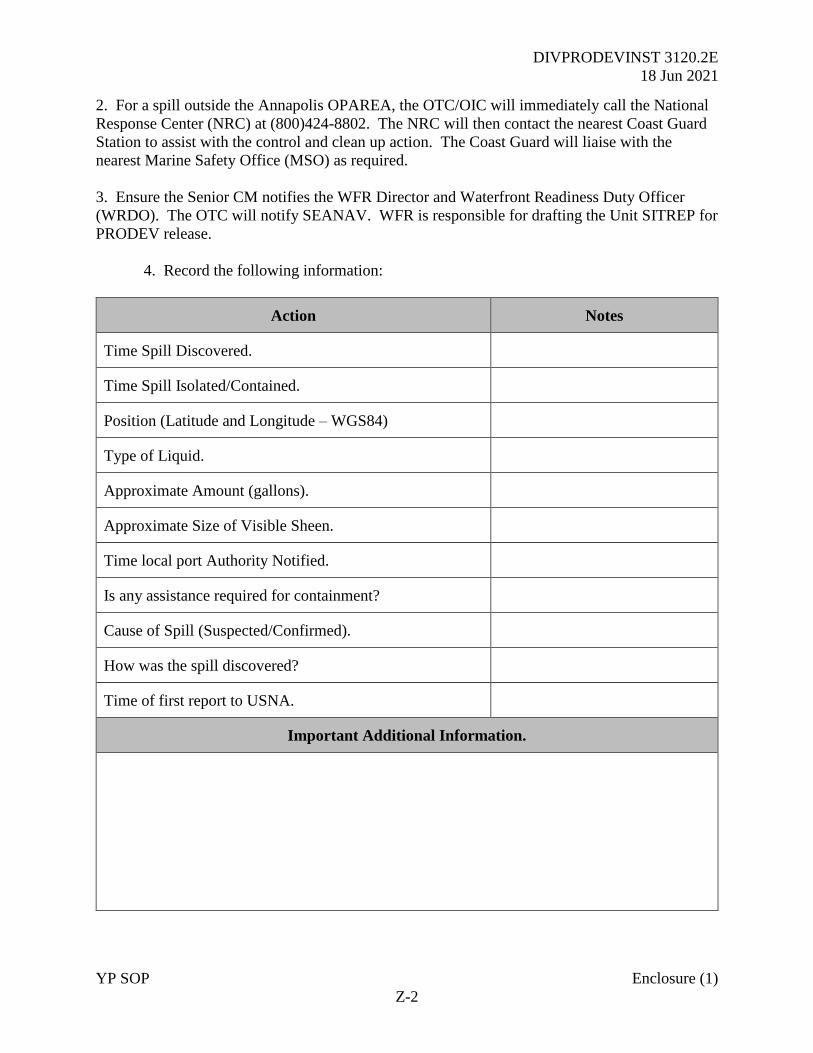
DIVPRODEVINST 3120.2E
18 Jun 2021
YP SOP Enclosure (1)
Z-2
2. For a spill outside the Annapolis OPAREA, the OTC/OIC will immediately call the National
Response Center (NRC) at (800)424-8802. The NRC will then contact the nearest Coast Guard
Station to assist with the control and clean up action. The Coast Guard will liaise with the
nearest Marine Safety Office (MSO) as required.
3. Ensure the Senior CM notifies the WFR Director and Waterfront Readiness Duty Officer
(WRDO). The OTC will notify SEANAV. WFR is responsible for drafting the Unit SITREP for
PRODEV release.
4. Record the following information:
Action Notes
Time Spill Discovered.
Time Spill Isolated/Contained.
Position (Latitude and Longitude – WGS84)
Type of Liquid.
Approximate Amount (gallons).
Approximate Size of Visible Sheen.
Time local port Authority Notified.
Is any assistance required for containment?
Cause of Spill (Suspected/Confirmed).
How was the spill discovered?
Time of first report to USNA.
Important Additional Information.
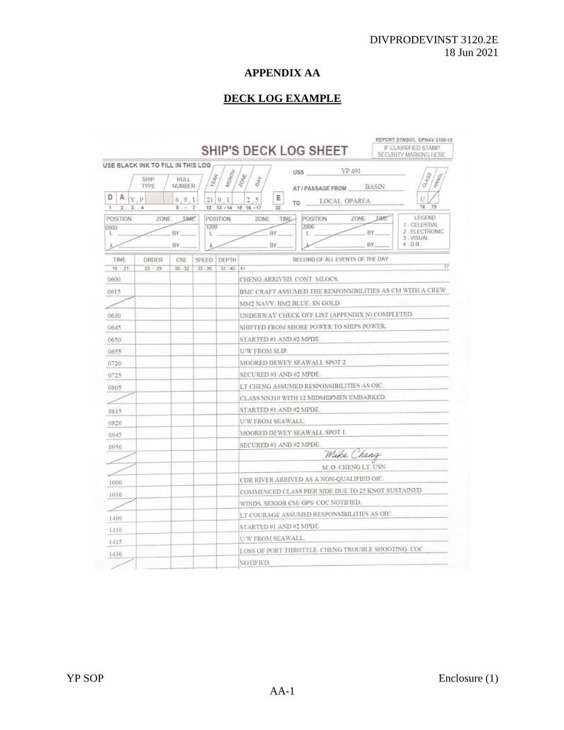
DIVPRODEVINST 3120.2E
18 Jun 2021
YP SOP Enclosure (1)
AA-1
APPENDIX AA
DECK LOG EXAMPLE
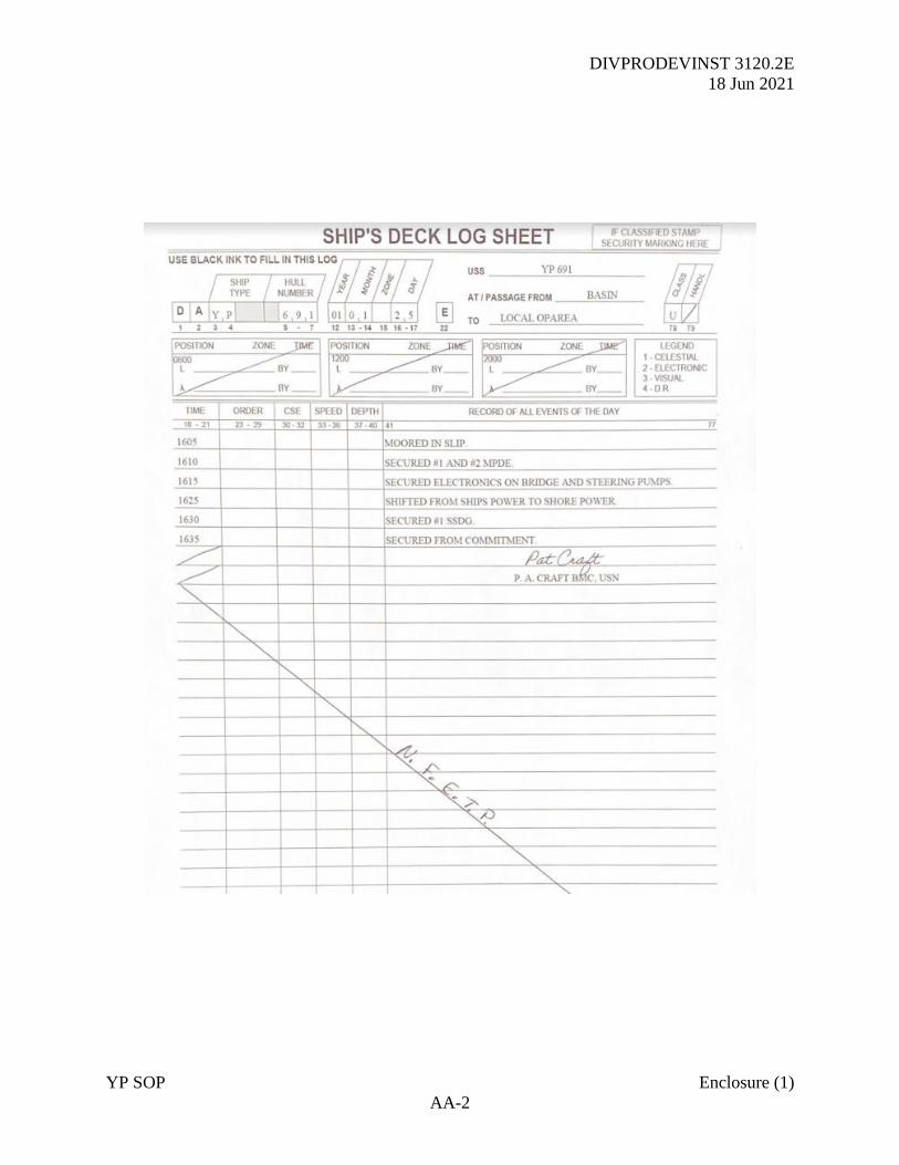
DIVPRODEVINST 3120.2E
18 Jun 2021
YP SOP Enclosure (1)
AA-2
DIVPRODEVINST 3120.2E
18 Jun 2021
YP SOP Enclosure (2)
i
YARD PATROL CRAFT
ENGINEERING AND SHIPHANDLING
GUIDE
Reviewed: Jan 2021

DIVPRODEVINST 3120.2E
18 Jun 2021
YP SOP Enclosure (2)
ii
CONTENTS
CHAPTER 1 - SHIPHANDLING GUIDE
CHAPTER 2 - ENGINEERING GUIDE
CHAPTER 3 - DAMAGE CONTROL SYSTEMS GUIDE
DIVPRODEVINST 3120.2E
18 Jun 2021
YP SOP Enclosure (2)
1-1
CHAPTER 1
SHIPHANDLING
1-1 Introduction. Safe and effective maneuvering of a YP requires an understanding of basic
hydrodynamic principles and a period of experience to master the craft. Often, low speed
evolutions such as pier landings prove to be the most challenging as the prevailing ephemeral
effects of wind and current have a far greater influence on the movement of the YP over ground.
The references offer advice on how to best tackle various naval shiphandling scenarios.
1-2 Shiphandling Forces. When piloting a vessel of any type, a mariner must consider both the
controllable and uncontrollable forces affecting the ship. Controllable forces can be created by
the use of propellers, rudder(s), mooring lines, anchors, or any attached tug or other boat.
Uncontrollable forces are created by the prevailing velocity and direction of both wind and tidal
stream or current. The flow of water around any ship creates a boundary layer and two
significant forces of thrust (F2) and drag (F1) (Figure 1) as well as resulting in pressure zones,
the effect of which increase with the size of vessel (Figure 2).
Figure 1 - Forces Around the Hull
Figure 2 - Pressure and Suction Zones
1-2.1 Propeller Effects
1. Both classes of YP use twin fixed-pitch propellers (FPPs) located at the stern of the craft;
offset either side of the centerline. FPPs turn outward when going ahead maximizing the

DIVPRODEVINST 3120.2E
18 Jun 2021
YP SOP Enclosure (2)
1-2
dynamic efficiency of the lateral turning forces created. Both the blades and boss of a FPP are
made as one solid unit and the blades are set at a fixed angle of attack.
2. As it is not possible to alter the pitch of the blade, the propeller must rotate in the opposite
direction when astern thrust is required. Astern thrust is achieved using a reserving gearbox. To
alter the amount of thrust generated by an FFP, the speed of rotation is either increased or
decreased (Figure 3) which will increase the pressure and suction causing the stern to move in a
given direction, thus generating a ‘Twist’. As both shafts then turn in the same direction, lateral
wash caused by flow of water acting against the stern of the craft may assist the turn (Figure 4).
Figure 3 - Pressure and Suction
Figure 4 - Lateral Wash
3. In situations where only a single shaft is used, such as from a casualty, the Paddlewheel
Effect is created by a single propeller rotating and delivering thrust (Figure 5).
Figure 5 - Paddle Wheel Effect
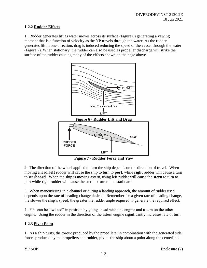
DIVPRODEVINST 3120.2E
18 Jun 2021
YP SOP Enclosure (2)
1-3
1-2.2 Rudder Effects
1. Rudder generates lift as water moves across its surface (Figure 6) generating a yawing
moment that is a function of velocity as the YP travels through the water. As the rudder
generates lift in one direction, drag is induced reducing the speed of the vessel through the water
(Figure 7). When stationary, the rudder can also be used as propeller discharge will strike the
surface of the rudder causing many of the effects shown on the page above.
Figure 6 - Rudder Lift and Drag
Figure 7 - Rudder Force and Yaw
2. The direction of the wheel applied to turn the ship depends on the direction of travel. When
moving ahead, left rudder will cause the ship to turn to port, while right rudder will cause a turn
to starboard. When the ship is moving astern, using left rudder will cause the stern to turn to
port while right rudder will cause the stern to turn to the starboard.
3. When maneuvering in a channel or during a landing approach, the amount of rudder used
depends upon the rate of heading change desired. Remember for a given rate of heading change,
the slower the ship’s speed, the greater the rudder angle required to generate the required effect.
4. YPs can be “twisted” in position by going ahead with one engine and astern on the other
engine. Using the rudder in the direction of the astern engine significantly increases rate of turn.
1-2.3 Pivot Point
1. As a ship turns, the torque produced by the propellers, in combination with the generated side
forces produced by the propellers and rudder, pivots the ship about a point along the centerline.
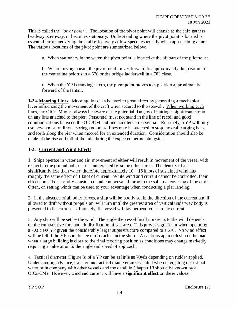
DIVPRODEVINST 3120.2E
18 Jun 2021
YP SOP Enclosure (2)
1-4
This is called the “pivot point”. The location of the pivot point will change as the ship gathers
headway, sternway, or becomes stationary. Understanding where the pivot point is located is
essential for maneuvering the craft effectively at low speed, especially when approaching a pier.
The various locations of the pivot point are summarized below:
a. When stationary in the water, the pivot point is located at the aft part of the pilothouse.
b. When moving ahead, the pivot point moves forward to approximately the position of
the centerline pelorus in a 676 or the bridge ladderwell in a 703 class.
c. When the YP is moving astern, the pivot point moves to a position approximately
forward of the fantail.
1-2.4 Mooring Lines. Mooring lines can be used to great effect by generating a mechanical
lever influencing the movement of the craft when secured to the seawall. When working such
lines, the OIC/CM must always be aware of the potential dangers of putting a significant strain
on any line attached to the pier. Personnel must not stand in the line of recoil and good
communications between the OIC/CM and line handlers are essential. Routinely, a YP will only
use bow and stern lines. Spring and breast lines may be attached to stop the craft surging back
and forth along the pier when moored for an extended duration. Consideration should also be
made of the rise and fall of the tide during the expected period alongside.
1-2.5 Current and Wind Effects
1. Ships operate in water and air; movement of either will result in movement of the vessel with
respect to the ground unless it is counteracted by some other force. The density of air is
significantly less than water, therefore approximately 10 – 15 knots of sustained wind has
roughly the same effect of 1 knot of current. While wind and current cannot be controlled, their
effects must be carefully considered and compensated for with the safe maneuvering of the craft.
Often, on setting winds can be used to your advantage when conducting a pier landing.
2. In the absence of all other forces, a ship will be bodily set in the direction of the current and if
allowed to drift without propulsion, will turn until the greatest area of vertical underway body is
presented to the current. Ultimately, the vessel will lay perpendicular to the current.
3. Any ship will be set by the wind. The angle the vessel finally presents to the wind depends
on the comparative fore and aft distribution of sail area. This proves significant when operating
a 703 class YP given the considerably larger superstructure compared to a 676. No wind effect
will be felt if the YP is in the lee of obstacles on the shore. A cautious approach should be made
when a large building is close to the final mooring position as conditions may change markedly
requiring an alteration to the angle and speed of approach.
4. Tactical diameter (Figure 8) of a YP can be as little as 70yds depending on rudder applied.
Understanding advance, transfer and tactical diameter are essential when navigating near shoal
water or in company with other vessels and the detail in Chapter 13 should be known by all
OICs/CMs. However, wind and current will have a significant effect on these values.

DIVPRODEVINST 3120.2E
18 Jun 2021
YP SOP Enclosure (2)
1-5
Figure 8 - Advance, Transfer and Tactical Diameter
1-3 Shiphandling Evolutions
1-3.1 Getting Underway from a Pier
1. Before getting underway, the Conning Officer should assess the direction and velocity of both
the wind and current and determine how this will affect the YP as lines are taken in. Before
letting go, ensure the outboard side and stern are clear and the craft is free to maneuver.
2. If the YP is being set off the pier, taking in all lines will allow the YP to drift away from the
pier. The bow or stern line could be held as necessary to control the rate of drift. When clear,
back out astern. If desired, you may move ahead but must be careful to ensure the stern is not
endangered by the pier or another moored craft as the pivot point takes the stern to the jetty.
3. If the YP is being set onto the pier or in a condition of slack water with light winds, take in
the stern line and twist the stern away from the pier to approximately 30° from the line of the
jetty. Release the bowline and back away from the pier with a 1/3 bell.
4. The method of departure will always depend on the prevailing conditions. The departure plan
should be clearly briefed to the Team, including line handlers, before getting underway.
1-3.3 Making a Landing
1. Considerations. To achieve a safe and controlled pier landing an accurate appraisal of the
prevailing environmental conditions (wind, current) and proximity of adjacent ships or other
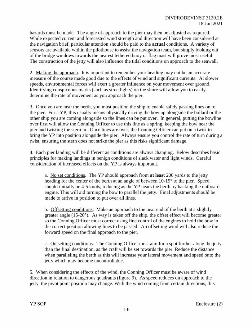
DIVPRODEVINST 3120.2E
18 Jun 2021
YP SOP Enclosure (2)
1-6
hazards must be made. The angle of approach to the pier may then be adjusted as required.
While expected current and forecasted wind strength and direction will have been considered at
the navigation brief, particular attention should be paid to the actual conditions. A variety of
sensors are available within the pilothouse to assist the navigation team, but simply looking out
of the bridge windows towards the nearest tethered buoy or flag mast will prove most useful.
The construction of the jetty will also influence the tidal conditions on approach to the seawall.
2. Making the approach. It is important to remember your heading may not be an accurate
measure of the course made good due to the effects of wind and significant currents. At slower
speeds, environmental forces will exert a greater influence on your movement over ground.
Identifying conspicuous marks (such as streetlights) on the shore will allow you to easily
determine the rate of movement as you approach the pier.
3. Once you are near the berth, you must position the ship to enable safely passing lines on to
the pier. For a YP, this usually means physically driving the bow up alongside the bollard or the
other ship you are coming alongside so the lines can be put over. In general, putting the bowline
over first will allow the Conning Officer to use this line as a spring, keeping the bow near the
pier and twisting the stern in. Once lines are over, the Conning Officer can put on a twist to
bring the YP into position alongside the pier. Always ensure you control the rate of turn during a
twist, ensuring the stern does not strike the pier as this risks significant damage.
4. Each pier landing will be different as conditions are always changing. Below describes basic
principles for making landings in benign conditions of slack water and light winds. Careful
consideration of increased effects on the YP is always important.
a. No set conditions. The YP should approach from at least 200 yards to the jetty
heading for the center of the berth at an angle of between 10-15° to the pier. Speed
should initially be 4-5 knots, reducing as the YP nears the berth by backing the outboard
engine. This will aid turning the bow to parallel the jetty. Final adjustments should be
made to arrive in position to put over all lines.
b. Offsetting conditions. Make an approach to the near end of the berth at a slightly
greater angle (15-20°). As way is taken off the ship, the offset effect will become greater
so the Conning Officer must correct using fine control of the engines to hold the bow in
the correct position allowing lines to be passed. An offsetting wind will also reduce the
forward speed on the final approach to the pier.
c. On setting conditions. The Conning Officer must aim for a spot further along the jetty
than the final destination, as the craft will be set towards the pier. Reduce the distance
when paralleling the berth as this will increase your lateral movement and speed onto the
jetty which may become uncontrollable.
5. When considering the effects of the wind, the Conning Officer must be aware of wind
direction in relation to dangerous quadrants (figure 9). As speed reduces on approach to the
jetty, the pivot point position may change. With the wind coming from certain directions, this
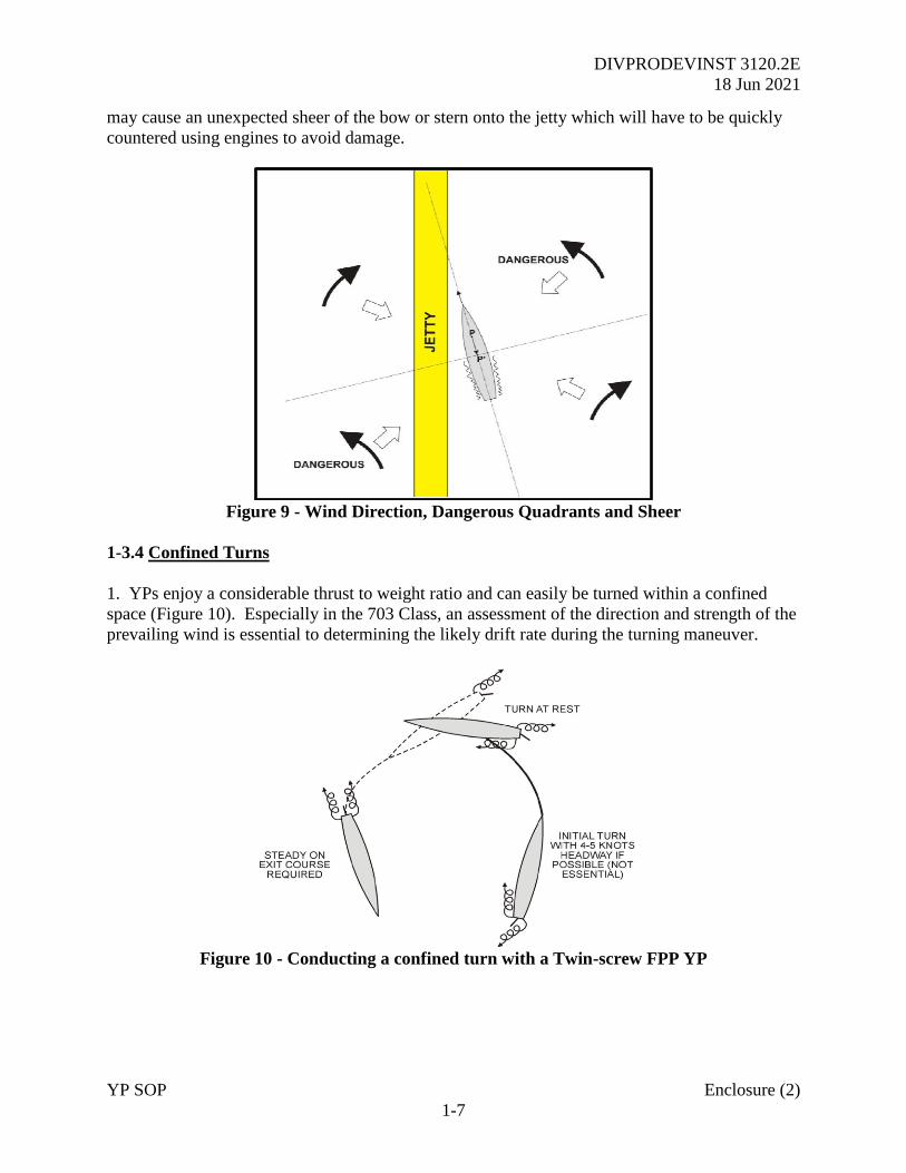
DIVPRODEVINST 3120.2E
18 Jun 2021
YP SOP Enclosure (2)
1-7
may cause an unexpected sheer of the bow or stern onto the jetty which will have to be quickly
countered using engines to avoid damage.
Figure 9 - Wind Direction, Dangerous Quadrants and Sheer
1-3.4 Confined Turns
1. YPs enjoy a considerable thrust to weight ratio and can easily be turned within a confined
space (Figure 10). Especially in the 703 Class, an assessment of the direction and strength of the
prevailing wind is essential to determining the likely drift rate during the turning maneuver.
Figure 10 - Conducting a confined turn with a Twin-screw FPP YP
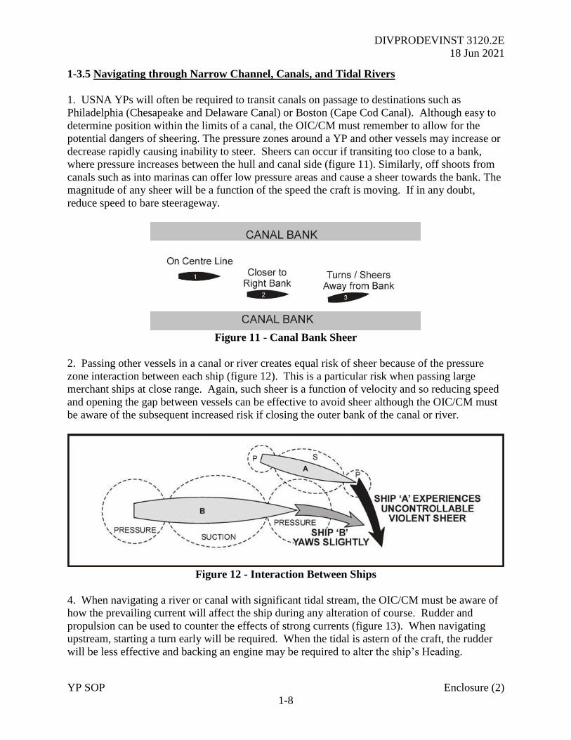
DIVPRODEVINST 3120.2E
18 Jun 2021
YP SOP Enclosure (2)
1-8
1-3.5 Navigating through Narrow Channel, Canals, and Tidal Rivers
1. USNA YPs will often be required to transit canals on passage to destinations such as
Philadelphia (Chesapeake and Delaware Canal) or Boston (Cape Cod Canal). Although easy to
determine position within the limits of a canal, the OIC/CM must remember to allow for the
potential dangers of sheering. The pressure zones around a YP and other vessels may increase or
decrease rapidly causing inability to steer. Sheers can occur if transiting too close to a bank,
where pressure increases between the hull and canal side (figure 11). Similarly, off shoots from
canals such as into marinas can offer low pressure areas and cause a sheer towards the bank. The
magnitude of any sheer will be a function of the speed the craft is moving. If in any doubt,
reduce speed to bare steerageway.
Figure 11 - Canal Bank Sheer
2. Passing other vessels in a canal or river creates equal risk of sheer because of the pressure
zone interaction between each ship (figure 12). This is a particular risk when passing large
merchant ships at close range. Again, such sheer is a function of velocity and so reducing speed
and opening the gap between vessels can be effective to avoid sheer although the OIC/CM must
be aware of the subsequent increased risk if closing the outer bank of the canal or river.
Figure 12 - Interaction Between Ships
4. When navigating a river or canal with significant tidal stream, the OIC/CM must be aware of
how the prevailing current will affect the ship during any alteration of course. Rudder and
propulsion can be used to counter the effects of strong currents (figure 13). When navigating
upstream, starting a turn early will be required. When the tidal is astern of the craft, the rudder
will be less effective and backing an engine may be required to alter the ship’s Heading.
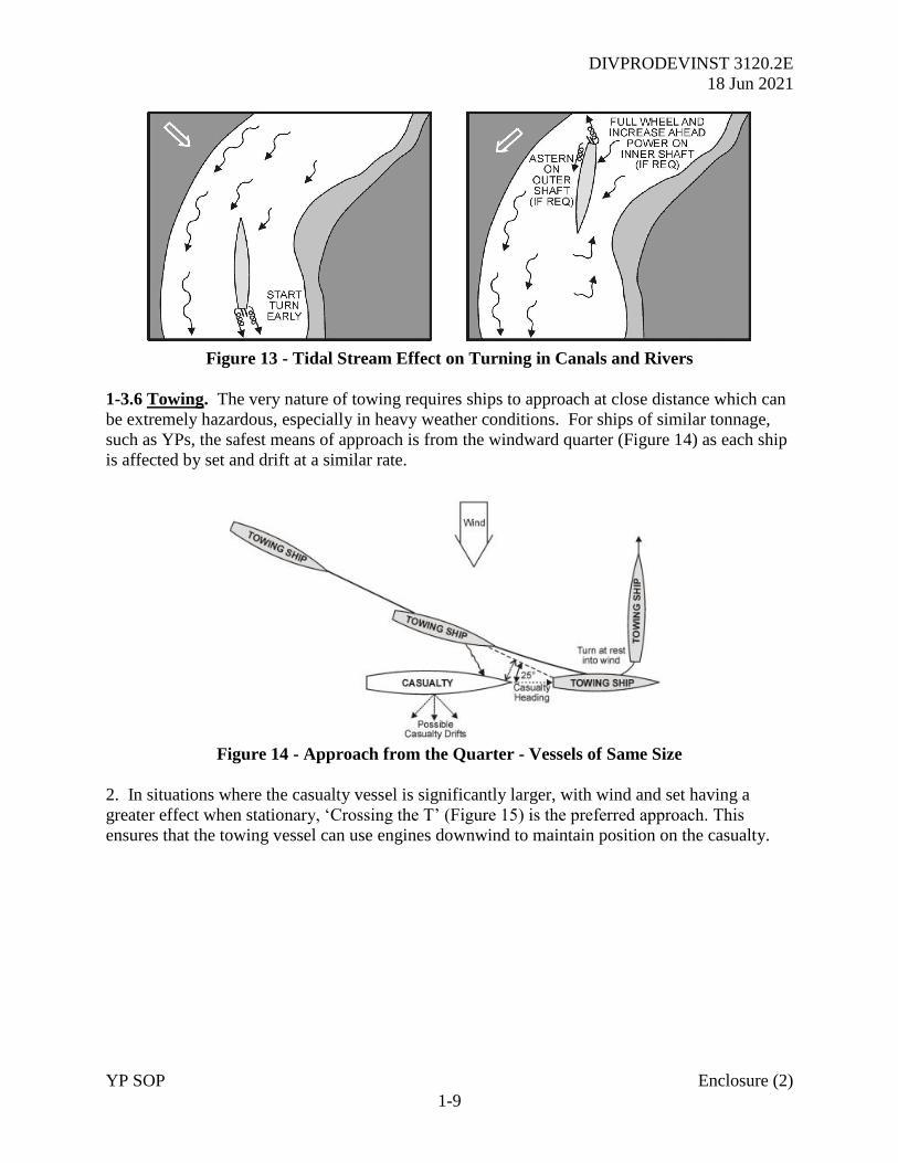
DIVPRODEVINST 3120.2E
18 Jun 2021
YP SOP Enclosure (2)
1-9
Figure 13 - Tidal Stream Effect on Turning in Canals and Rivers
1-3.6 Towing. The very nature of towing requires ships to approach at close distance which can
be extremely hazardous, especially in heavy weather conditions. For ships of similar tonnage,
such as YPs, the safest means of approach is from the windward quarter (Figure 14) as each ship
is affected by set and drift at a similar rate.
Figure 14 - Approach from the Quarter - Vessels of Same Size
2. In situations where the casualty vessel is significantly larger, with wind and set having a
greater effect when stationary, ‘Crossing the T’ (Figure 15) is the preferred approach. This
ensures that the towing vessel can use engines downwind to maintain position on the casualty.
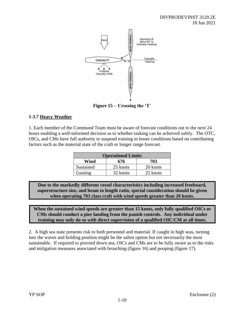
DIVPRODEVINST 3120.2E
18 Jun 2021
YP SOP Enclosure (2)
1-10
Figure 15 - Crossing the ‘T’
1-3.7 Heavy Weather
1. Each member of the Command Team must be aware of forecast conditions out to the next 24
hours enabling a well-informed decision as to whether tasking can be achieved safely. The OTC,
OICs, and CMs have full authority to suspend training in lesser conditions based on contributing
factors such as the material state of the craft or longer range forecast.
Operational Limits
Wind 676 703
Sustained 25 knots 20 knots
Gusting 32 knots 25 knots
Due to the markedly different vessel characteristics including increased freeboard,
superstructure size, and beam to length ratio, special consideration should be given
when operating 703 class craft with wind speeds greater than 20 knots.
When the sustained wind speeds are greater than 15 knots, only fully qualified OICs or
CMs should conduct a pier landing from the panish controls. Any individual under
training may only do so with direct supervision of a qualified OIC/CM at all times.
2. A high sea state presents risk to both personnel and material. If caught in high seas, turning
into the waves and holding position might be the safest option but not necessarily the most
sustainable. If required to proceed down sea, OICs and CMs are to be fully aware as to the risks
and mitigation measures associated with broaching (figure 16) and pooping (figure 17).
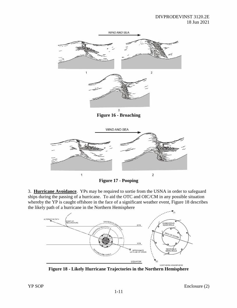
DIVPRODEVINST 3120.2E
18 Jun 2021
YP SOP Enclosure (2)
1-11
Figure 16 - Broaching
Figure 17 - Pooping
3. Hurricane Avoidance. YPs may be required to sortie from the USNA in order to safeguard
ships during the passing of a hurricane. To aid the OTC and OIC/CM in any possible situation
whereby the YP is caught offshore in the face of a significant weather event, Figure 18 describes
the likely path of a hurricane in the Northern Hemisphere
Figure 18 - Likely Hurricane Trajectories in the Northern Hemisphere
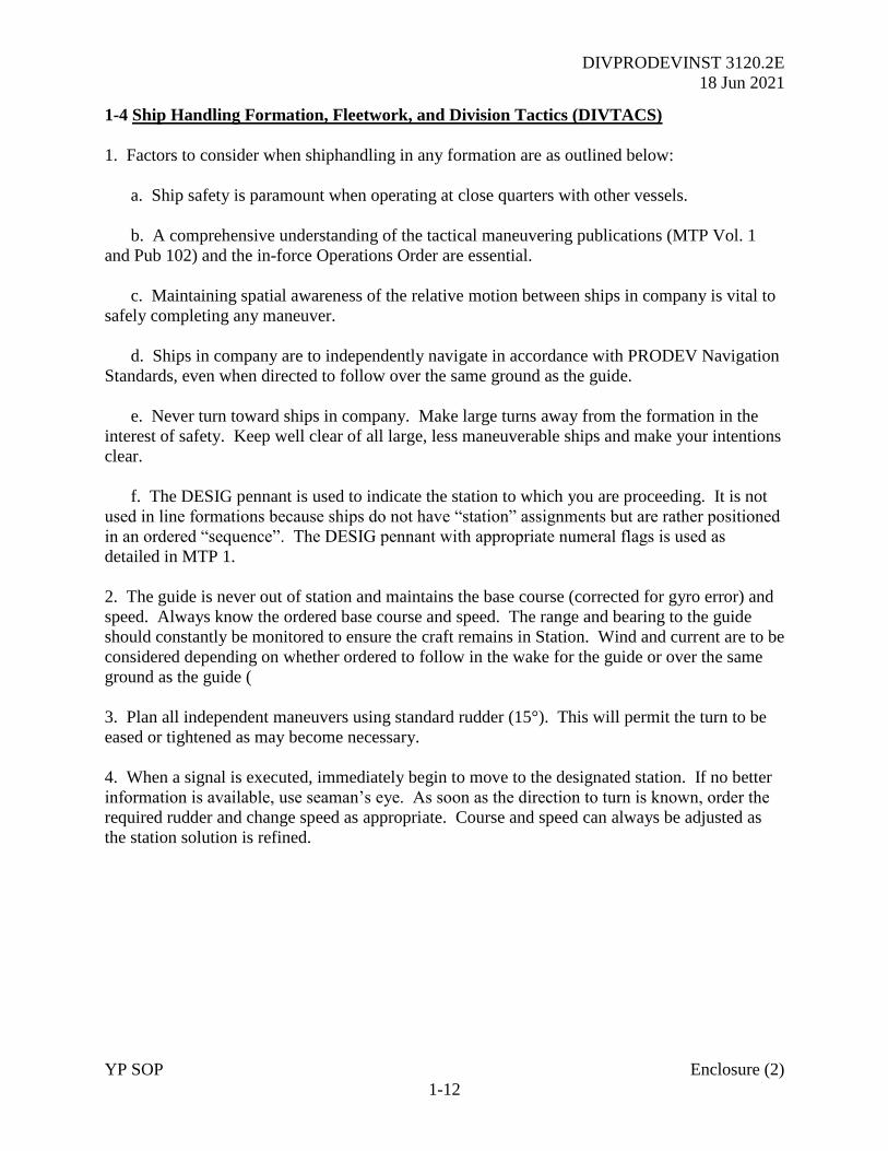
DIVPRODEVINST 3120.2E
18 Jun 2021
YP SOP Enclosure (2)
1-12
1-4 Ship Handling Formation, Fleetwork, and Division Tactics (DIVTACS)
1. Factors to consider when shiphandling in any formation are as outlined below:
a. Ship safety is paramount when operating at close quarters with other vessels.
b. A comprehensive understanding of the tactical maneuvering publications (MTP Vol. 1
and Pub 102) and the in-force Operations Order are essential.
c. Maintaining spatial awareness of the relative motion between ships in company is vital to
safely completing any maneuver.
d. Ships in company are to independently navigate in accordance with PRODEV Navigation
Standards, even when directed to follow over the same ground as the guide.
e. Never turn toward ships in company. Make large turns away from the formation in the
interest of safety. Keep well clear of all large, less maneuverable ships and make your intentions
clear.
f. The DESIG pennant is used to indicate the station to which you are proceeding. It is not
used in line formations because ships do not have “station” assignments but are rather positioned
in an ordered “sequence”. The DESIG pennant with appropriate numeral flags is used as
detailed in MTP 1.
2. The guide is never out of station and maintains the base course (corrected for gyro error) and
speed. Always know the ordered base course and speed. The range and bearing to the guide
should constantly be monitored to ensure the craft remains in Station. Wind and current are to be
considered depending on whether ordered to follow in the wake for the guide or over the same
ground as the guide (
3. Plan all independent maneuvers using standard rudder (15°). This will permit the turn to be
eased or tightened as may become necessary.
4. When a signal is executed, immediately begin to move to the designated station. If no better
information is available, use seaman’s eye. As soon as the direction to turn is known, order the
required rudder and change speed as appropriate. Course and speed can always be adjusted as
the station solution is refined.
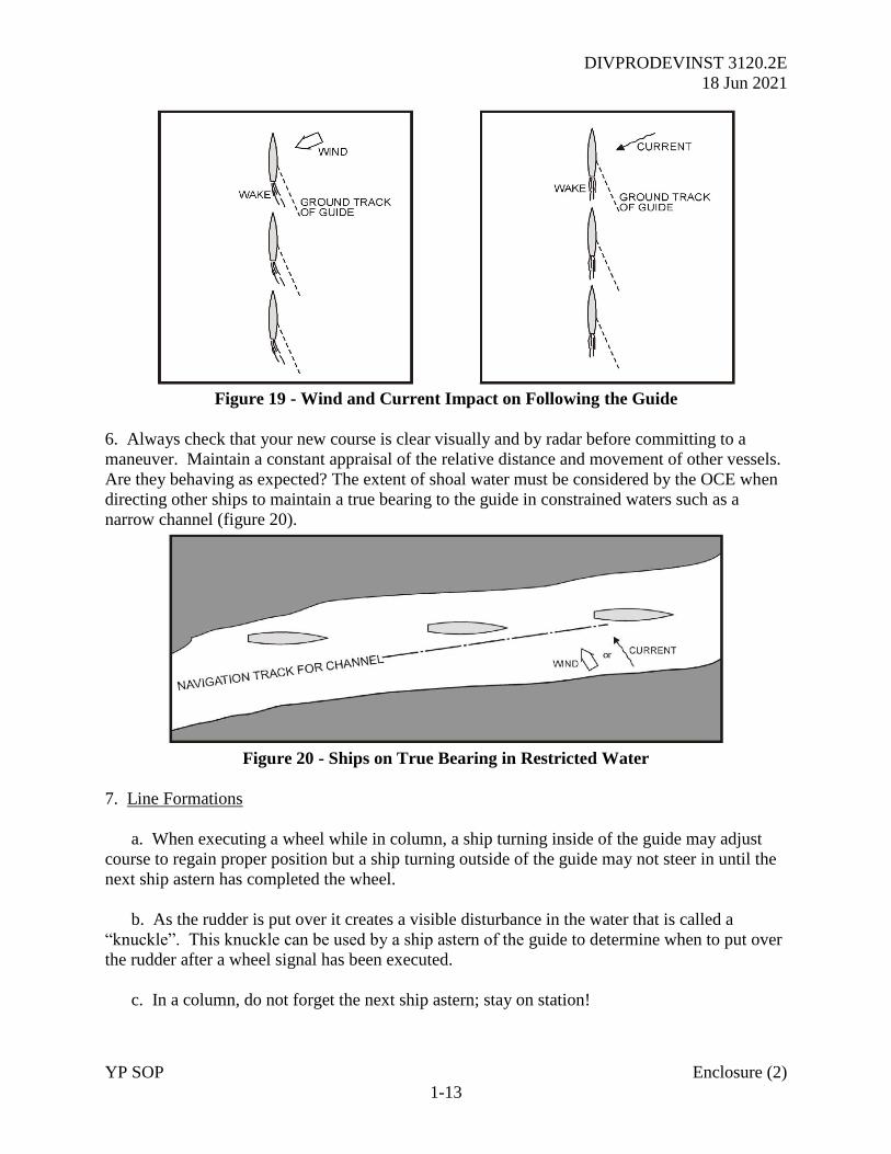
DIVPRODEVINST 3120.2E
18 Jun 2021
YP SOP Enclosure (2)
1-13
Figure 19 - Wind and Current Impact on Following the Guide
6. Always check that your new course is clear visually and by radar before committing to a
maneuver. Maintain a constant appraisal of the relative distance and movement of other vessels.
Are they behaving as expected? The extent of shoal water must be considered by the OCE when
directing other ships to maintain a true bearing to the guide in constrained waters such as a
narrow channel (figure 20).
Figure 20 - Ships on True Bearing in Restricted Water
7. Line Formations
a. When executing a wheel while in column, a ship turning inside of the guide may adjust
course to regain proper position but a ship turning outside of the guide may not steer in until the
next ship astern has completed the wheel.
b. As the rudder is put over it creates a visible disturbance in the water that is called a
“knuckle”. This knuckle can be used by a ship astern of the guide to determine when to put over
the rudder after a wheel signal has been executed.
c. In a column, do not forget the next ship astern; stay on station!
DIVPRODEVINST 3120.2E
18 Jun 2021
YP SOP Enclosure (2)
1-14
d. When falling into an ordered station astern of another ship and you are both turning in the
same direction, ensure your bow is never inside her stern as you turn.
8. Formations and Screens When a signal is received which may affect the ship’s station, the
OIC/CM must determine the following:
a. New station number.
b. Range and bearing to the guide when on station.
c. Direction to turn.
d. The course at stationing speed to get into station.
9. Station Keeping
a. Make every effort to maintain an accurate station while in formation, frequently checking
the bearing and range of the guide. (+/- 3° for bearing, +/- 10% for range)
b. Maintain station by making appropriate changes in course and speed. If the bearing and
range of the guide are frequently checked, only small course and speed changes will be necessary
to keep the ship on station.
c. When in column, remember which number your ship is in the sequence. In the event of an
emergency procedure, even numbered ships turn to port and odd numbered ships turn to
starboard.
d. As a change of base course is executed, an error in station keeping can be easily corrected
by adjusting the timing of your turn and the amount of rudder used.
e. Radar can be a useful tool to aid with the task of maintaining station, ensure it is properly
configured for optimum performance.
DIVPRODEVINST 3120.2E
18 Jun 2021
YP SOP Enclosure (2)
2-1
CHAPTER 2
ENGINEERING GUIDE
2-1 Shipboard Responsibility. The enlisted engineer (second class petty officer or above) is
responsible to the OIC/CM for the complete readiness, maintenance, and operation of all
engineering systems onboard. This includes propulsion, electrical generation, ventilation, and all
other hotel services including MSD/CHT. Out of Area, additional specialist personnel (such as
an ET) will be embarked.
2-2 676 Class Engineering Equipment
2-2.1 Main Engines
1. Main propulsion of the 676 class YP is supplied by Detroit Diesel 12V71 series diesel
engines. Each unit is a 12-cylinder diesel engine coupled to transfer gear by hydraulically
operated clutches. These are nonreversible, injection 2-cycle engines, with associated fuel, lube
oil and water cooling systems and mechanical governor. Each engine produces up to 437 SHP.
A summary of the cooling systems is shown below.
a. Fresh Water (FW) Cooling. The cooling of the main propulsion unit consists of one
closed loop FW system on each engine and a split open loop salt water system that is used to
cool the fresh water within the heat exchangers. The salt water is later mixed with the exhaust
and discharged overboard. The closed FW system has a 32-quart capacity of fresh water (and
antifreeze when required). The coolant is drawn by a centrifugal pump from the bottom of the
engine lube oil cooler. Circulation is first through the transmission/reverse gear oil cooler then
the engine oil cooler and finally through the engine. After passing through the centrifugal pump,
the water is circulated through the cylinder block and head. Upon leaving the cylinder head, the
coolant flows through the water manifold into the thermostat housing; from there the coolant
either flows down through the tubes of the heat exchanger, through the oil coolers (and back
again to the water pump), or the coolant bypasses the heat exchanger, goes through the oil
coolers, and returns to the water pump. Bypassing the heat depends upon the coolant
temperature. Below 160°F, the spring operated thermostat valve is closed and the coolant
completely bypasses the heat exchanger on its way to the oil coolers. At 160°F, the valve begins
to open, allowing coolant to flow through the heat exchanger and opens further as the coolant
temperature increases. At 185°F, the valve is fully open allowing maximum flow through the
heat exchanger. The FW pump can pump at a rate of 109 gallons each minute when the engines
are operating at 2,100 RPM.
b. 175°F is the normal operating temperature and reading above 195°F necessitates an
immediate investigation.
c. Salt Water (SW) Cooling. Salt water enters the system through a seacock located aft of
the engines and passes through a duplex strainer to the SW circulation pump. These are positive
displacement pumps, which pump at a rate of approximately 74 gallons per minute when the
engines are operating at 2100 RPM. Care should be taken to avoid the loss of SW suction (due
DIVPRODEVINST 3120.2E
18 Jun 2021
YP SOP Enclosure (2)
2-2
to ice, floating debris, etc.) because this will cause the neoprene impellers of the pump to
overheat and cause the hard rubber to deform. Salt water flows from these pumps to the fuel/oil
cooler then to the stern tube packing and heat exchanger where it will cool fresh water entering
from the manifold at approximately 160-185°F. Salt water is discharged from the heat
exchanger and then flows overboard through the V-1 valves and to the engine exhaust pipes
where it cools the exhaust.
d. Lube Oil (LO) System. The lubricating oil is circulated by a gear-type pressure pump
from the rear of the crankshaft. The gear train is lubricated by the overflow of oil from the
camshaft pocket spilling into the gear train compartment and by splash from the oil pan. The
blower drive gear bearing is lubricated through an external pipe from the blower rear end plate to
the blower drive support. The valve and injector operating mechanism are lubricated from a
longitudinal oil passage on the camshaft side of each cylinder head, which connects to the main
oil gallery in the cylinder block. The oil passes through a duplex full flow oil filter to remove
solid contaminants.
2-2.2 Generators
1. Ship’s electrical power is provided by two in line 3-71 Detroit Diesel generators producing
450V, 3 phase at 60Hz, 50KW and 80 amps for all onboard systems. The cooling systems
associated with the electrical generators are markedly similar to the main engines.
a. Cooling Systems. The FW pump on the SSDG can pump at a rate of 84 gallons per
minute when operating at 1,800 RPM. The SW pump can pump at a rate of 57 gallons per
minute.
b. Lube Oil (LO) System. Lube oil flow through the SSDG is again almost identical to the
main engine, with two minor differences. Firstly, the lube oil passes through a simplex rather
than a duplex filter. Secondly, the oil pan for the main engine is tilted while the SSDG oil pan is
flat. Otherwise, the lube oil pump is driven by the crankshaft and is attached to the same place
on the crankshaft as the oil pump for the MPDE.
c. Lube Oil Transfer and Storage System. The LO is stored in the lube oil storage tank
located on the port bulkhead in the engine room. This tank has a capacity of 40 gallons and is
filled from piping leading from the main deck fill at frame 40, port side amidships.
d. The purpose of the drain system is to provide rapid lubrication oil change capability for
the MPDEs and the reduction gears. The portable oil evacuation pump’s suction is attached to
the main engine’s quick connecting attachment. The suction hose takes suction on the sump.
The portable evacuation pump then discharges the lube oil to the lube oil waste tank that is
located next to the lube storage tank on the port bulkhead of the engine room. The lube oil waste
tank has a capacity of 32 gallons. The generator has a six-gallon capacity to hold lube oil.
2-2.3 Gyrocompass

DIVPRODEVINST 3120.2E
18 Jun 2021
YP SOP Enclosure (2)
2-3
1. The gyrocompass system indicates the heading of the craft. The system consists of the Sperry
Marine, NAVISTAR satellite compass, gyrocompass unit, and ship’s course indicators (gyro
repeaters). The power supply is 115V for the synchro distribution system. An automatic transfer
switch between the converter and the gyro provides emergency 24V DC power from the ship’s
batteries. The gyrocompass is also connected to the S-Band radar and VMS computer.
2. The master gyrocompass is located on the pilothouse helmsman Station. Five more gyro
repeaters that indicate heading are located throughout the craft.
2-2.4 Circuits/Alarms
1. The following circuits and alarms are found in engineering spaces.
a. Circuit “E” Sound Powered Telephone Call Bell System. This system provides for calls
between stations on the sound powered telephone 1 JV circuit. Power supply for buzzer and bell
is 115V AC fed from the IC panel.
b. Circuit 1EC Lubrication Oil Pressure Alarm System. This system is installed on the two
MPDEs and SSDGs for indicating a loss of pressure in the lubricating oil system. The alarm
panel is located on the front side of the control console. Loss of pressure (less than 10 PSI) will
cause the alarm panel to sound. The power supply is 24V DC.
c. Circuit 1EW Circulating Water High Temperature Alarm System. A thermostat switch is
located in each of the MPDEs and SSDGs circulating systems. An excessive temperature rise
(greater than 195°F) will cause the alarm buzzer to sound. The power supply is 24V DC.
d. Circuit KM Engine Revolution Indicator System. This system provides an indication of
the RPM of the MPDEs. The system consists of a tachometer generator installed on each engine
and a radial indicator located in the pilothouse at the panish controls.
e. Circuit MB, Engine Order Telegraph System (Mechanical). This system is no longer
operable in any craft.
2-2.5 Engine Order Telegraph System. The engines in the 676 class YP are routinely operated
in bridge control and the EOT system is no longer operable.
2-2.6 Panish Controls
1. 676 class YPs are fitted with a set of panish controls for remote operation of the engines from
the bridge. The system consists of two control levers (one for each MPDE). When starting the
main engines, control shall remain in the engine room.
2. When using panish controls, the engine room will remain manned at all times when operating
at sea detail, making landings or operating in proximity to other craft.
2-3 676 Class Engineering Systems
DIVPRODEVINST 3120.2E
18 Jun 2021
YP SOP Enclosure (2)
2-4
2-3.1 Electrical Distribution System
1. AC electrical system is used to energize the ship’s lighting system, communications, and
navigation systems, electric motors, and other equipment.
a. The system includes two 3L71 diesel engines that generate power at 450V, 50KW, 80A,
three-phase at 60 Hz. Routinely, one SSDG will be online with the other serving as a backup.
For shore power, a 75-foot long cable is located forward on the main deck in the center of the
superstructure. This is used to supply 450V from ashore when available.
b. 450V AC. The SSDGs are connected to 450V panel, which is located on the aft bulkhead
of the EOS. The power flows from the Electric Plant panel to the 450V Bus Transfer panel
located on the starboard side of the EOS. From this panel the power flows to the transformers
located on the main deck on the starboard side of the passageway between the officer berthing
and CIC. Power then flows to the 450V non-vital power distribution panel that is located on the
starboard side of the divider between the two MPDEs. From here, the electricity is supplied to
the non-essential systems such as the brominator, the desalinator, and the air conditioning
seawater pump.
c. 115V AC. The three transformers mentioned above convert the 450V, 3 Phase, 60 Hz
power and supply it to the seven power distribution panels located throughout the craft. The
vital IC distribution panel located on the starboard aft bulkhead in the pilothouse provides power
to the essential internal communications, such as the 1MC and 21MC. The isolated receptacle
circuit distribution panel located amidships on the forward bulkhead of the same passageway
provides power to the critical receptacles located in the pilothouse, CIC, and engine room. The
vital distribution panel amidships on the forward bulkhead in the engine room provides power to
the fuel transfer pumps, MSD compressor, battery charger, and other vital ships systems. The
non-vital power distribution panel located on the forward wall of the galley, supplies power to
the less critical ships systems which include the dishwasher, refrigerator, toaster, ice maker, and
trash compactor. The vital light distribution panel, located on the forward bulkhead in forward
passageway, provides power to the lights, such as searchlights. The vital auxiliary power panel
located on the forward wall of the passageway between the officer stateroom and CIC, just
forward of the ladder to midshipmen berthing provides power to the necessary auxiliary systems,
such as the air replenishment system, the berthing exhaust system, the defogger, and the sump
pump.
d. 24V DC. The AC system also provides 24V DC using the rectifier located on the forward
engine room bulkhead. This rectifier is supplied by 115V AC and transforms it to 24V DC. The
DC system is also supplied by the craft’s emergency batteries.
2. DC electrical system is used to provide a 24V supply for starting the MPDEs, SSDGs, and the
emergency power panel. The main components of the DC system are the charging rectifier,
batteries, paralleling circuit, the selector switch, and the DC emergency power distribution panel
in the pilothouse.
DIVPRODEVINST 3120.2E
18 Jun 2021
YP SOP Enclosure (2)
2-5
a. Batteries. The charging rectifiers are located in the engine room. On the forward
bulkhead across from the starboard MPDE. They automatically convert the 115V AC from the
vital distribution panel to 24V DC. This power is fed into 24V battery banks and two 12V
batteries in series used for the generators. The batteries are located in the engine room, directly
in front of the EOS. There are two banks of batteries, each bank consisting of eight cells that
provide a total of 24V in each. The two banks of batteries provide power to start the MPDEs.
b. Batteries are automatically charged by the charging rectifiers. The charging rectifiers are
usually kept on, even when the engines and generator are off. If the batteries were to drop
substantially below 24V DC, the charger would immediately be put into operation and begin to
charge the batteries at the rated output to a predetermined voltage.
c. The paralleling circuit is located on the console in EOS for the MPDEs. When batteries
are operated in parallel, they produce more power. The parallel switch for the SSDG’s is located
on the switchboard.
d. The 24V DC distribution panel is located in the pilothouse across from the ladder leading
to CIC. It provides power to the following systems even if the AC electrical system were to fail.
(1) Navigation Light panel.
(2) Rudder Angle Indicator and Underwater Log.
(3) Sperry Marine NAVISTAR Satellite Gyro Compass.
(4) HF Radio Transceiver.
(5) UHF Radio Transceiver.
(6) FM 200 System.
(7) VHF Radio.
(8) E-Call System (Internal Communications).
(9) Pilothouse Console Dimmer/Lighting.
(10) Windshield Wipers.
(11) HD/HE Circuits (Wind Direction and Speed Indicator System).
(12) Emergency Lighting System.
e. Electrical load reductions should be in-force when operating on only the 24V DC system.
3. There are certain precautions to be taken when working with or around the battery systems.
DIVPRODEVINST 3120.2E
18 Jun 2021
YP SOP Enclosure (2)
2-6
a. Keep all naked lights well clear.
b. Never charge a battery at a higher finishing rate than given on its nameplate.
c. Lower the charging rate as soon as battery water temperature reaches 125°F.
d. Do not make repairs to battery connections when current is flowing.
e. When using tools around a battery, be careful not to short circuit battery terminals.
f. Always pour acid slowly into water and never water into acid. Guard skin and eyes
against splashes of acid using the appropriate protective equipment.
g. Exercise proper care in handling acid.
h. Do not add acid of greater specific gravity then 1.350 to a battery.
i. Do not store sulfuric acid in places exposed to freezing temperatures.
j. Keep electrolyte level above tops of separators.
k. Add only pure distilled water to a battery.
l. Do not, except in an emergency, discharge battery below the given low voltage limit.
m. Never allow the battery to stand in a completely discharged condition for more than 24
hours.
n. Do not operate any battery above 125°F.
o. Do not discard battery in a fire because it may explode.
2-3.2 Fuel Oil System
1. The purpose of the fuel oil system is to provide fuel for the operation of the diesel MPDEs
and SSDGs. It is composed of two onboard storage tanks, associated piping, and the equipment
necessary for filling, venting, sounding, stripping, supply, return, and transfer of fuel.
2. Equipment Location. There are two 3,401-gallon fuel tanks, one port and starboard, located
in the fuel tank compartment 2-30-0-T. The tanks are filled through two fill connections located
at frame 34 on the main deck. The fuel tanks have all the connections necessary for supply,
return, transfer, fill vent, sounding, filtering, and stripping the fuel. There are remote indicating
gauges located at the EOS to monitor the amount of fuel left in each tank. These gauges are
graduated in 100-gallon increments with numerical increments every 500 gallons. There are
combination vent and sounding caps located port and starboard at frame 33 on the main deck.
DIVPRODEVINST 3120.2E
18 Jun 2021
YP SOP Enclosure (2)
2-7
These serve the dual purpose of venting the tanks and providing the capability to sound each of
the tanks.
a. Located between the two fuel tanks is a 25 gallon stripping tank and pump. The rotary
hand pump draws fuel out of the tank and through associated piping and valves to the stripping
tank. A sight glass allows the operator to view the fuel being stripped and to see when all the
water has been removed from the tank. The stripping tank has a drain valve in the bottom
allowing it to be drained into a portable container. Once the stripping tank is full, it overflows
into the starboard fuel oil tank. This allows usable fuel to be returned to the system for
consumption.
b. As the fuel leaves the fuel tanks, it is strained and filtered with a knife-edge strainer
located in each tank between the fuel cutoff valve and the fuel service manifold. This allows
removing any contamination or sediment that found its way into the tanks. These are the
primary strainers.
c. From the fuel oil service manifold on its way to the engines the fuel passes through
fuel/water separators. These will remove any remaining water from the fuel before entering the
engines and/or diesel generators. The fuel/water separators provide servicing clearance to drain
entrapped water into a bucket. They are located on the suction side of each propulsion and
generator engine. Return fuel from the engines is piped to the top of each fuel tank.
d. There is an electrically driven transfer pump located in the engine room along the
centerline on the forward bulkhead. The transfer pump is provided for diesel engine priming,
fuel transfer from tank to tank, and offloading the tanks to the main deck offloading connection
located at frame 38 on the starboard side.
e. An important element in the fuel oil system is the emergency fuel shutoff valve. This is
used to shutoff all supply lines where fuel flows from the tanks to the engines. These shutoff
valves are located at the fuel discharge pipe of each tank and can be remotely operated with T-
bar handles located in the CIC forward bulkhead. Either or both tanks can be selected for shutoff
in case of fire or other engine room emergency.
2-3.3 Hydraulic Steering System
1. The hydraulic steering system is a mechanical hydraulic full follow-up power steering system.
The system provides steering power using a basic manual hydraulic system to control the
rudders. The system consists of nine basic components including the helm, jog lever, emergency
wheel, rudders, pumps, hydraulic fluid, actuator, tie-bar, and follow-up sub-system.
a. Helm. The main helm is a large steering wheel located in the center of the pilothouse.
Rotation of the helm in a clockwise direction causes the rudder to turn towards the right, while
rotation of the helm in the counter-clockwise direction causes the rudder to turn towards the left.
The helm can be used with or without the electric hydraulic pumps.
DIVPRODEVINST 3120.2E
18 Jun 2021
YP SOP Enclosure (2)
2-8
b. Jog lever. The jog lever is a single “stick-shift” device used to control the rudder angle
and steer the craft when both a helmsman and a lee-helmsman are not available. It is clearly
marked and located on the port side of the pilothouse. As opposed to the helm, which employs
rotational motion to control the rudders, the jog lever employs simple lateral motion to affect the
same result. Unlike the helm, which has little or no lag time upon being turned, the jog lever has
an approximate two second delay from being placed in a direction and the rudders actual turning.
The jog lever will override the helm.
c. Emergency wheel. Emergency wheel is a helm used to control the rudders in the event of
a loss of electrical power or casualty of the actuator or pumps. It is located on the forward
bulkhead, port side of the lazarette. This should be used only in the event of a casualty or
emergency as accurate control of the rudders becomes much more difficult.
d. Pumps. Any hydraulic steering system requires the flow of fluid, under high pressure, to
be pumped throughout the system. Two Reughler 3 HP, 1,800-RPM pumps provide the
necessary pressure for the hydraulic system onboard. They are vane pumps located amidships in
the lazarette. Although two pumps are installed, only one is necessary for full steering
capability. Because of this, only one pump should be used at any time. There is an additional,
smaller pump located in the pilothouse console. This pump provides the pressure necessary to
position the telemotor cylinder.
e. A follow-up transmitter is installed on the telemotor cylinder piston rod. This transmitter
provides feedback to monitor position of the rudder. It compares the actual position of the
rudder to the ordered position of the rudder and corrects it as necessary.
2. Casualties. In the event of a casualty resulting in the loss of electrical power to the hydraulic
actuator or the loss of pumping ability by the electric motor driven pumps, the steering control
located at the bridge helm will automatically revert to a manual hydraulic pump. This pump can
provide full steering capabilities, but rudder response will occur much more slowly and much
more effort will be required. In normal wheel steering, four revolutions of the helm provide a
full range of motion for the rudder. This is accomplished in approximately eight seconds. In
manual mode, twelve revolutions of the helm are required for a full range of motion of the
rudder. This is accomplished in approximately 15 seconds. When normal wheel steering is lost,
the jog lever will become inoperable.
a. Should the pilothouse control unit become inoperable due to a damaged hose, damaged
pipe, or other mechanical malfunction, steering control must be executed from the emergency
wheel steering unit in the lazarette. Before this unit becomes operable, valves tagged (1), (2),
(3), and (4) must be closed and valves tagged (5), (6), and (7) must be opened. These valves are
located on the steering actuator and are clearly marked. Failure to properly align these valves
will quickly drain the hydraulic fluid storage tank, causing the entire steering system to become
inoperable.
b. A double relief valve has been installed to act as a shock absorber in the event the rudder
strikes a solid object causing structural damage. This valve allows hydraulic fluid to spill from
DIVPRODEVINST 3120.2E
18 Jun 2021
YP SOP Enclosure (2)
2-9
the high-pressure side of the T-ram to the low-pressure side and thus relieve some of the stress
on the system.
2-3.4 Ventilation System
1. This system operates using both natural and mechanical supply and exhaust. Natural supply
and exhaust is obtained by windows or vents open to the outside. Mechanical supply and
exhaust is obtained by inducting fresh air into the ship dispelling stale air by natural circulation.
2-3.5 Potable Water System
1. Potable water is supplied by a fresh water system that distributes fresh water throughout the
craft. There are numerous outlets located onboard for obtaining fresh water for drinking,
showering, dishwashing, ice making, and deck washing. A majority of the main components of
the potable water system are located in the engine room below the main deck between frames 36
and 50. Other main components are located throughout the vessel in the galley, mess room, and
bilges. The main components are desalinator, potable water storage tanks, recirculating bromine
feeder, water pressure system, and electric water heater tanks.
a. The water pressure system allows water to be distributed throughout the vessel. The
system consists of two tanks, a water pump, an automatic switch, a filter assembly, and a
pressure gauge. The system is located on the port side, aft in the engine room. The pressure tank
contains a seamless bag filled with air. The water pump automatically will pump water into the
tank around the bag. The water is supplied to the pressure tank by the potable water storage
tanks through the water pump. Before the water enters the tank, it first passes through an
activated carbon filter. This process makes the water more pleasant to drink. When the pressure
reaches 40 PSI, the water pump will automatically shut off. The water in the tank can now be
sent throughout the ship to the other various systems. As water is used throughout the vessel, the
pressure will drop. When the pressure drops to about 25 PSI, the water pump will activate and
repressurize the tank.
b. The potable water storage tanks contain the ready supply of fresh water for the various
uses throughout the vessel. The forward potable water storage tank is located in the engine room
bilge (just aft of frame 36) and has a capacity of 1,133 gallons. The aft potable water storage
tank is located in the mess room bilge (between frames 50 and 56) and has a capacity of 399
gallons. The water level for each tank can be monitored by two gauges located in the EOS. The
water level gauges are graduated in 25-gallon increments with numerical readings in 100-gallon
increments. To operate the gauges, pump the plunger underneath each gauge four or five times
to activate the gauge. These gauges must be monitored when filling the potable water storage
tanks. The tanks can be filled from a shore installation (normally) or another vessel. The
potable water storage tanks should be filled before every out of area deployment.
c. The electric water heater is a tank receiving its water from the potable water system and
raises the temperature electrically through a heater element to a desired amount. The hot water is
used for showers, dish washing, etc. There are two water heater tanks onboard. The port tank is
located in the forward port corner of the engine room. It has a capacity of 50 gallons. The
DIVPRODEVINST 3120.2E
18 Jun 2021
YP SOP Enclosure (2)
2-10
starboard tank is located in the forward starboard corner of the engine room, with a capacity of
80 gallons. These tanks are filled automatically by the potable water pressure system. The water
pressure is also maintained by the potable water pressure system. The outputs of each of these
tanks are connected and routed from the engine room to outlets throughout the vessel.
d. The bromine feeder is a dispenser that sends a predetermined amount of bromine to the
potable water storage tanks. It is located in the engine room above the deck over the forward
potable water storage tank. The chemical ensures the water in the potable water storage tanks
remains safe for consumption. For a detailed description of operation and maintenance, refer to
NAVSEA TECHNICAL MANUAL 59533-AK-MMO-010. This system uses cartridges not to
be stored onboard the vessel.
e. The sump tanks contain water that has been used in showers, sinks, and drinking
fountains. There are two 30-gallon tanks onboard. The forward 30-gallon tank is located in the
bilge between frames 24 and 26 and the aft 30-gallon tank is located in the bilge between frames
59 and 61. Each tank is fitted with a removable cover for periodic cleaning and a 35 GPM at 35-
PSI discharge pump for draining overboard. The officer’s washroom drains and the galley sinks
can be drained directly overboard. Tank vents are located 18 inches above the main deck at
frames 23 port and 56 aft. The tanks are designed to automatically discharge overboard when an
80% level has been reached. The tanks can be manually operated by a switch located in the
space roughly above each tank. The positions of the switch are AUTO-MAN-OFF. The switch
should be kept in the AUTO position at all times. Systems are located in the engine room below
the main deck between frames 36 and 50. Other main components are located throughout the
vessel in the galley, mess room, and bilges. The main deckhouse procedure is the same as
connecting a garden hose to an angle valve and turning it on.
f. Deck Wash-down. The outside deck can be washed using the fresh water from the potable
water system. A hose can be connected to a deck wash-down connection located forward or aft
of the craft.
2-3.6 Marine Sanitation Device (MSD)
1. This system collects sanitary waste from reduced volume-flush water closets and holds the
sewage in the 302-gallon holding tank. The tank, located in the bilge between frames 17 and 22,
is provided with a discharge pump and deck connections for pumping the tank sewage to proper
shore sanitation facilities. Seawater drawn from a seacock by the flushing pump provides the
water for flushing operations. The flushing pump is actuated by a switch connected to the water
closet flushing linkage.
a. The pump is automatically controlled by the timing circuit control and is turned on each
time the heads are flushed.
b. The pump transports the waste and slurry to the sewage holding tank. The pump
continues to run for a preset period. A check valve located at the pump outlet prevents any
backflow of wastes after pump shutoff.
DIVPRODEVINST 3120.2E
18 Jun 2021
YP SOP Enclosure (2)
2-11
c. The transfer pump is supplied with a magnetic starter that has an exterior manual override
switch allowing the pump to be operated to clear or check it. This switch is also used to start the
discharge pump for sewage holding tank pump-out.
2-4 Propulsion System Emergency Safeties and Shutdowns
1. The propulsion system consists of two diesel engines. In case of an emergency, these engines
have been equipped with safeties, such as lights and alarms meant to warn personnel of
malfunction. These engines are also equipped with emergency cutoffs that will shut down the
engines. Additionally, there are cutoffs for the port and starboard generators, along with
shutdowns for the port and starboard fuel oil supplies. The Engine Operating Station (EOS) is
equipped with controls for these cutoffs, safety controls, and alarms.
2. Emergency Engine Shutdown. The cutoffs for the port and starboard fuel oil supplies are
controlled by two T-handles in the CIC. When these T-handles are pulled, all fuel flow to the
system is stopped. This cutoff is needed in case of a ruptured fuel line. Although cutting the
fuel supply will not shut down the system immediately, the fuel would stop leaking from the line.
The engine will continue to burn the fuel already supplied to it, and will shut down after this fuel
has been completely used.
a. There are T-handles that cut the air off to the MPDEs and SSDGs located in EOS and the
aft passageway forward of the entrance to the mess deck. These are used when the engine must
be shut down immediately.
b. These T-handles are labeled by space name. Two further T-handles are dedicated to the
operation of the FM 200 system.
3. Alarms. There are safety alarms for both the MPDEs and SSDGs for which a buzzer will
sound and an indicator light will go on in the EOS if there is low oil pressure or high water
temperature. The parameters for these malfunctions are 10-PSI oil pressure for MPDEs, 20-PSI
oil pressure for SSDGs, and 205°F for temperature.
a. The alarms in the EOS are located on the port side of the control console.
b. If one of these alarms sounds, an operator cannot tell whether the malfunction is low oil
pressure or high temperature. The gauges on the engine must be checked to confirm which
malfunction has occurred. There are also lights, but no buzzers located in the pilothouse, for
each of these malfunctions.
c. When any of these alarms are activated, the procedures outlined in Engineering
Operational Casualty Control (EOCC), are to be followed.
2-5 703 Class Engineering Systems
2-5.1 Main Engines
DIVPRODEVINST 3120.2E
18 Jun 2021
YP SOP Enclosure (2)
2-12
1. The propulsion plant consists of two, EPA Tier II, diesel marine propulsion engines. These
are Caterpillar model C18 533 bkW (715 BHP) 2100 RPM, driving one fixed pitch propeller
through an attached ZF W2350 vertical offset reverse reduction gearbox with a 4:1 ratio. The
coupling is directly mounted to the engine. A Caterpillar power display for each engine is
located on the Pilothouse Control Console (PHCC) by the helm. There are also Local Operating
Controls (LOC) located on each engine. The plant is fitted with an integrated control and
monitoring system. The engines are cooled by heat exchangers and ingest combustion air
directly from the atmosphere in the compartment.
a. Cooling Systems
(1) The Freshwater (FW) or “jacket water” system is used to cool each main diesel
engine. The closed-loop jacket water cooling system has a 12-gallon capacity of freshwater and
antifreeze mix. Make-up for the engine cooling systems is from the craft’s FW system. Each
diesel engine jacket water cooling system consists of an engine driven circulating pump,
necessary piping and valves, and jacket water to seawater shell and tube type heat exchanger. A
thermostat will divert jacket water around the cooler when required. When the valve is fully
open all jacket water will pass through the cooler.
(2) A saltwater (SW) cooling system is provided to remove heat from each main engine,
reduction gear, and generator engine’s heat exchanger. SW enters through a 12-inch sea chest
located between frames 20 and 21, passes through a 6-inch simplex strainer to a motor driven
centrifugal seawater pump, through an intercooler, to jacket water cooler then branches to stern
tube cooling, transmission oil cooler and overboard. SW supply to main engine heat exchangers
and reduction gears comes from the main sea chests. Although SW supply to all engines comes
from individual sea chests, the system can also be crossed connected. For example, the port
main engine can be supplied with seawater from the starboard main engine sea chest.
b. Lube Oil (LO) System
(1) A gear driven pump draws suction from a sump, through a strainer. After the pump,
the oil will pass through a duplex filter (with a full flow emergency bypass). The oil then will go
through molded 10-11 passages throughout the engine to lubricate major components, such as
pistons, crankshaft, camshaft, valves, and other various components. The oil will then pass
through a plate type cooler (cooled by jacket water), before returning to the sump.
(2) The LO system is installed onboard to store and supply clean lube oil to the main
engines and generator engines. Both the main engines and generators use the same type of lube
oil.
(3) Clean lube oil can be embarked from a deck connection at main deck (frame 25+, port
side) into a 52-gallon lube oil tank installed in the engine room (frame 24+, port side). A sight
glass is installed on the tank to indicate tank level contents. Lube oil is supplied to the engines
by operating a rotary hand pump and a hose. The hose is stored in the engine room on a reel and
is extended to reach each engine.
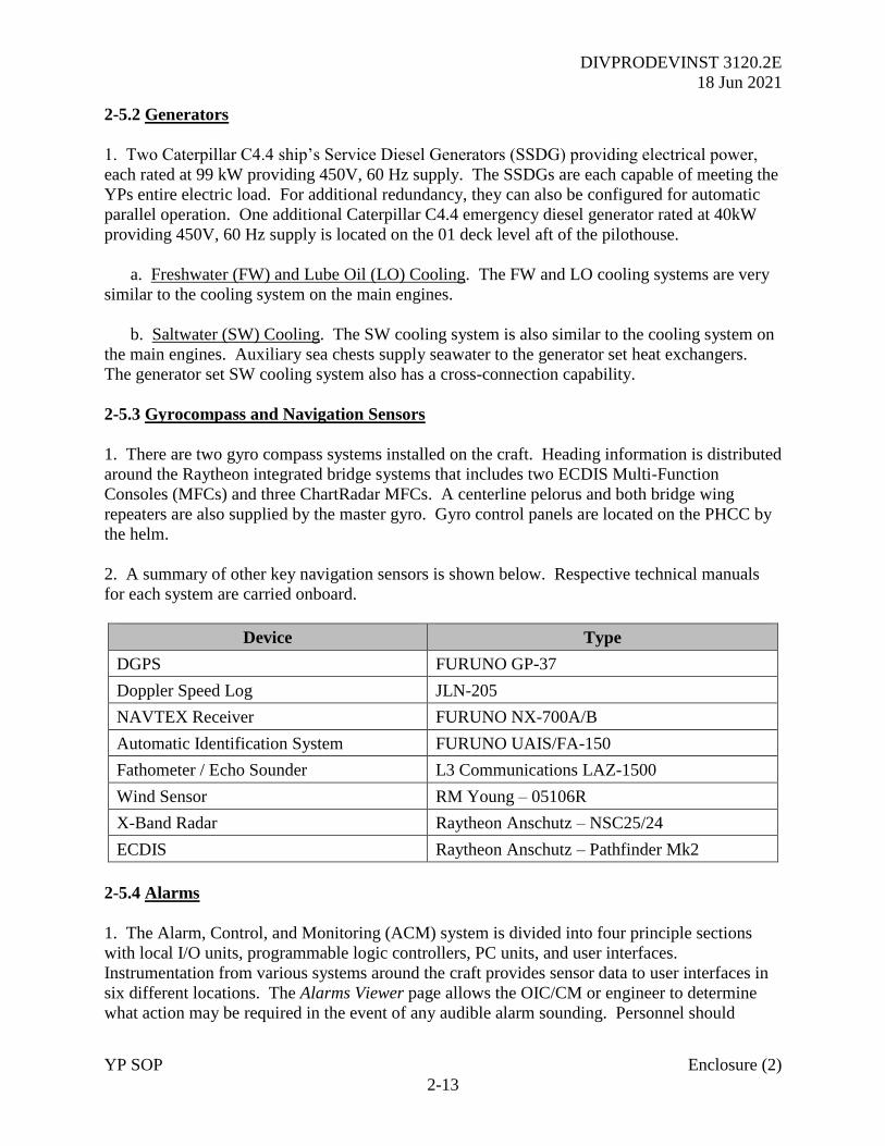
DIVPRODEVINST 3120.2E
18 Jun 2021
YP SOP Enclosure (2)
2-13
2-5.2 Generators
1. Two Caterpillar C4.4 ship’s Service Diesel Generators (SSDG) providing electrical power,
each rated at 99 kW providing 450V, 60 Hz supply. The SSDGs are each capable of meeting the
YPs entire electric load. For additional redundancy, they can also be configured for automatic
parallel operation. One additional Caterpillar C4.4 emergency diesel generator rated at 40kW
providing 450V, 60 Hz supply is located on the 01 deck level aft of the pilothouse.
a. Freshwater (FW) and Lube Oil (LO) Cooling. The FW and LO cooling systems are very
similar to the cooling system on the main engines.
b. Saltwater (SW) Cooling. The SW cooling system is also similar to the cooling system on
the main engines. Auxiliary sea chests supply seawater to the generator set heat exchangers.
The generator set SW cooling system also has a cross-connection capability.
2-5.3 Gyrocompass and Navigation Sensors
1. There are two gyro compass systems installed on the craft. Heading information is distributed
around the Raytheon integrated bridge systems that includes two ECDIS Multi-Function
Consoles (MFCs) and three ChartRadar MFCs. A centerline pelorus and both bridge wing
repeaters are also supplied by the master gyro. Gyro control panels are located on the PHCC by
the helm.
2. A summary of other key navigation sensors is shown below. Respective technical manuals
for each system are carried onboard.
Device Type
DGPS FURUNO GP-37
Doppler Speed Log JLN-205
NAVTEX Receiver FURUNO NX-700A/B
Automatic Identification System FURUNO UAIS/FA-150
Fathometer / Echo Sounder L3 Communications LAZ-1500
Wind Sensor RM Young – 05106R
X-Band Radar Raytheon Anschutz – NSC25/24
ECDIS Raytheon Anschutz – Pathfinder Mk2
2-5.4 Alarms
1. The Alarm, Control, and Monitoring (ACM) system is divided into four principle sections
with local I/O units, programmable logic controllers, PC units, and user interfaces.
Instrumentation from various systems around the craft provides sensor data to user interfaces in
six different locations. The Alarms Viewer page allows the OIC/CM or engineer to determine
what action may be required in the event of any audible alarm sounding. Personnel should
DIVPRODEVINST 3120.2E
18 Jun 2021
YP SOP Enclosure (2)
2-14
always be vigilant to properly investigate each alarm, mindful that several may occur at once and
alarms that are more urgent may be missed by spurious messages.
2-5.5 Engine Order Telegraph System (EOT)
1. The EOT is located on the PHCC and the secondary unit is in the MCC. As the main engines
are routinely operated in bridge control, this system is rarely used outside of pre-planned training
serials or engineering casualty drills.
2-6 YP 703 Class Engineering Systems
2-6.1 Electrical Distribution System
1. The AC electrical system is primarily used to energize ship’s lighting, communications,
navigation system, electric motors, and other equipment.
a. 120V AC Power Distribution Systems. The 120V, 3 phase, 60 Hz power is supplied by a
120V switchboard located in the EOS (via four distribution panels located throughout the craft)
and through the 120V emergency panel connected to the emergency switchboard. This
switchboard receives power from two 450V/120V transformers located in EOS (connected to the
main switchboard).
b. 450V AC Power Distribution System. The main switchboard, located at the forward EOS
bulkhead, distributes 450V AC, 3 phase, 60 Hz power to MCC #1 (P401 port), MCC #2 (P401
starboard) and other 450V services. Both MCC #1 and MCC #2 are also located in EOS.
c. The MCC #1 supplies power to RO plant, AC cooling pump, ER supply fan #1, ER
exhaust fan #1, fuel oil transfer pump #1, MSD backwash pump, steering compartment supply
fan, ER/steering compartment, immersion heaters, oily water pump, electric hot water heater and
anchor windlass.
d. The MCC #2 supplies power to fire pump #2, chilled/hot water circ. pump, ER supply fan
#2, ER exhaust fan #2, sewage collection system, graywater discharge pump, electric hot water
heater, range/oven and sewage collection system. Main switchboard port and starboard
distribution panels are located in MCC and supply 450V power as follows:
(1) Port Panel. Steering pump #2, cathodic protection, HVAC immersion heater
(accommodations), transformer #1.
(2) Starboard Panel. A/C chill water, transformer #2 and EVAC system. Emergency
switchboard 450V distribution section is located in the emergency generator room and supplies
power to fire pump #1, bilge pump and steering gear hydraulic pump #1.
e. The emergency switchboard also supplies power to the emergency 120V power panel,
through a transformer also located in the emergency generator room. The emergency power
panel directly supplies both emergency lighting and electronic systems.
DIVPRODEVINST 3120.2E
18 Jun 2021
YP SOP Enclosure (2)
2-15
2. DC Electrical System
a. 24V DC is provided by three power supplies serving three separate panels (two connected
to 120V switchboard, one connected to 120V emergency panel). All DC panels have an
individual battery backup.
b. The 24V DC communication and navigation aid panel is located in CIC, forward of frame
19 inside the WTD. Two batteries are provided for backup power.
c. The 24V DC engine room panel is located within the engine room, starboard side on
frame 24. It has one set of two batteries for backup power. The panel has a 225A battery
disconnect.
d. The emergency 24V DC panel is located in CIC, forward of frame 19 inside the WTD. It
has one set of two batteries for backup power. The panel has a 225A battery disconnect.
2-6.2 Fuel Oil System
1. Action should be taken by the OIC, CM, and YP Engineer to ensure the fuel level in the
service tanks is maintained above 60% when operating underway.
2. The onboard fuel system is comprised of two systems. They are a fuel oil transfer system and
a fuel oil supply and return system.
a. The purpose of fuel oil transfer system is to transfer fuel between storage tanks, fuel oil
service tanks, and from storage and service tanks to the waste oil tank. The fuel oil transfer
system is also used to embark and disembark fuel. Fuel embarkation/ disembarkation points are
located at main deck (frame 27, port, and starboard). An emergency fuel shutdown is located at
frame 19 starboard side next to the ventilation shutdown. This push button closes six motorized
valves in the engine room, port and starboard main engine fuel supply valves, port and starboard
generator diesel engine fuel supply valve, mid-fuel oil tank cut off valve, and the lube oil transfer
valve. This is the ONLY remote fuel oil shutdown outside of the engine room. This will starve
the main engines and cause them to shut down and stop the craft. However, this is done only in
an emergency, as it will also shut down diesel generators supplying power. The emergency
diesel generator will then supply a reduced electrical load to the craft.
b. The fuel oil supply and return system supplies clean diesel fuel to the main engines and
the generator engines. Main engines and generator engine supply lines are installed with duplex
fuel oil filter separators. The emergency diesel generator has its own fuel oil system.
Emergency generator fuel oil is supplied from its own fuel oil tank, on the 01 level, which is
filled by fuel oil transfer system. Duplex filter separator is fitted in emergency diesel supply
line.
c. Fuel tanks are constructed with adequate vents, fill lines, baffles, and supply/return lines.
The full fuel carrying capacity (98%) of craft is 6,718 gallons. A gate valve is installed before
DIVPRODEVINST 3120.2E
18 Jun 2021
YP SOP Enclosure (2)
2-16
each fuel tank in the fill line from the main deck. Remotely operated valve actuators are
installed in all tank supply lines for emergency shut-off of the fuel supply. Two fuel oil supply
stop valves are located upstream of each engine, one at the tank and the other before the strainer.
There are check valves installed on all return lines.
2-6.3 Hydraulic Steering System
1. Operation
a. Directional control of the craft is accomplished by rudders controlled from the PHCC or
the Craftmaster Control Station (CMCS) in the pilothouse, the MCC in the engine room, or the
manual helm in the steering gear compartment. Three electronic controls, one each on the
CMCS and the PHCC are installed in the pilothouse and linked to the autopilot and the third is
located on the MCC console in the engine room. Hydraulic controls are installed on the
Hydraulic Power Unit (HPU) in the steering gear room. The pilothouse allows for simultaneous
operations of the two rudders. Rudder commands are entered into the system by the operator’s
movement of a lever, wheel, or knob to generate an electrical signal, which is used to energize
the solenoid valves located at the hydraulic power unit. The solenoid valves control the flow of
hydraulic fluid from the pump into and out of hydraulic cylinders or rams, which are attached, at
one end, to the rudder tiller arms and, at the other end, to the vessel’s structure.
b. The selected motor driven pumps on the hydraulic power unit supplies hydraulic oil to the
solenoid operated, directional control valves (4-way valves) and the divert/unloading valves.
Electrical signals from one of the rudder command input devices (e.g. follow-up wheel/amp,
non-follow-up lever, or autopilot) are used to energize the left or right solenoid of the directional
control valves. Hydraulic oil, which would otherwise be returned to the reservoir, is ported to
the hydraulic steering cylinders to position the rudder.
2. Hydraulic Power Unit (HPU)
a. The hydraulic oil system is an integral part of the steering gear system where two HPU’s
(port and starboard hydraulic power units) maintains their own supply of hydraulic oil
(conforming to MIL-L-17672, symbol 2110TH or any hydraulic oil having a viscosity of 150
SUS at 100°F). Each HPU holds about 20 gallons of hydraulic oil. The port and starboard units
both have a hydraulic cylinder on each rudderpost supplied by a separate piping system from
each HPU. This system allows continued use of the hydraulic system in the event of piping
failure of either the main steering gear system or auxiliary steering gear system. For emergency
use, an emergency steering hand pump is installed to steer the craft.
b. The major components of the HPU are the hydraulic vane pump, a 5-HP electric motor,
dual fluid reservoir, four solenoid operated directional control valves, and two relief valves.
c. The dual pump unit and associated components convert electrical rudder orders into a
hydraulic fluid flow that moves and holds the rudders at an ordered angle. Variable
displacement hydraulic vane pumps are provided. Each vane pump is driven by a 3 horsepower,
1,800 revolutions per minute, electric motor. The electrical power source is the ships 440V AC,
DIVPRODEVINST 3120.2E
18 Jun 2021
YP SOP Enclosure (2)
2-17
3 phase, 60Hz distribution system. The directional control valve ports hydraulic fluid from the
pumps to the proper ram or cylinder ports upon receipt of electrical commands. In normal
steering conditions with no electrical commands, the entire fluid flow from the pump is returned
to the reservoir via the 4-way valve. When the directional control valve receives a rudder
command, it will port the fluid from the pump out to the cylinders or the rams. The hydraulic
cylinders are used to directly position the rudder. The body of each hydraulic cylinder is
attached, on one end, to the structure of the vessel. The piston rod extending from the other
opposite end of the hydraulic cylinder is attached to the rudder tiller arm. Hydraulic fluid, under
pressure, flows into one end of the hydraulic cylinder and out of the other end forcing the piston
within the cylinder to move either into or out of the cylinder. The piston is attached to the piston
rod, and thus when the piston is forced to move, the piston rod also moves and causes the rudder
to move also. When fluid is not flowing into or out of the hydraulic cylinder, the piston, and
piston rod the rudder cannot move. The flow of hydraulic fluid into and out of the hydraulic
cylinders is provided by the dual hydraulic power unit under the control of the solenoid valves.
d. The feedback unit is located in a casing. The transmitter shaft is mechanically connected
with the rudderstock or with the positioning element of the steering gear. The actual or desired
position of the rudder blade is picked off by an additional precision potentiometer, which is
connected via a cable to the amplifier. The rudder movement imported to the drive shaft of the
feedback unit by coupling, lever, or sprocket wheel is passed on by the drive spur gear in the
feedback unit to the precision potentiometer for the rudder angle indicator equipment. This
potentiometer receives an approx. 10V DC power supply from the amplifier and produces a
voltage dependent on the rudder angle and is fed to the amplifier.
2-6.4 Ventilation System
1. This system uses of both natural and mechanical supply and exhaust. Natural supply and
exhaust is obtained by windows or vents directly open to the outside. Mechanical supply and
exhaust is obtained by inducting fresh air into the ship and dispel stale air by natural circulation.
a. On both the port and starboard sides, the engine room has two supply fans (4800 CFM
each) and two exhaust fans (3000 CFM each). The controllers are located at the upper level of
the engine room. Both fans are two speeds of operation. Individual fan speed may be selected to
suit ambient conditions. In cold weather, low speed may be selected to maintain the correct
temperature. Both the main engines and generators ingest air from the compartment. Both the
supply and exhaust vents are fitted with automatic closures. In the event of a fire in the engine
room, the ventilation can be secured from three locations outside of the space; pilothouse, fantail
at the FM-200 space, and main deck starboard side at frame 20.
b. The emergency generator compartment has no forced supply or exhaust ventilation. The
ventilation openings are fitted with automatic closures. In the event of a fire in the space, the
closures can be activated from outside of the space and the pilothouse.
c. Steering compartment has one supply fan (500 CFM) and a natural exhaust duct.
DIVPRODEVINST 3120.2E
18 Jun 2021
YP SOP Enclosure (2)
2-18
d. Solid waste stowage compartment has natural supply louver and an exhaust fan (50 CFM)
installed at frame 13 1/2 on the port side.
e. Ventilation for the Heads is provided by three exhaust fans. They are installed at main
deck, (frame 8 portside) and at tank top level (frames 2 and 9 starboard side).
2-6.5 Potable Water System
1. The potable water system produces, stores, and distributes cold and hot fresh water onboard.
The craft has two separate potable water tanks. Potable water can be produced onboard by using
the Reverse Osmosis (RO) unit located in the steering compartment and is rated at 1,056 gallons
per 24 hours. The RO unit forces sea or brackish water at high pressure through a
semipermeable membrane thereby producing potable water. The water is purified through a
proportioning bromine feeder. The bromine feeder is located on the aft bulkhead in the steering
compartment. This system is not often used and careful management of potable water
consumption is required for long periods underway.
2. Potable water can be embarked onboard from a shore connection into two separate tanks,
through the main deck filling connections located at frame 21 on both port and starboard sides.
The forward potable water tank 3-4-0-W, located at frame 4, has a 98% capacity of 857 gallons.
The aft potable water tank, 2-29-0-E located at frame 29, has a 98% capacity of 2,855 gallons.
Potable water is distributed by FW pressure at approximately 50-60 PSI and 15 GPM.
3. The hot water demands are met by two 50-gallon hot water tanks located in the steering
compartment where water is heated and then distributed by a five GPM circulation pump. The
hot water temperature can be adjusted from 120°F to 180°F. Each tank is equipped with a 100-
PSI relief valve.
4. Non-potable water requirements, window wiper/washer, sanitary spaces, engine room, and
eyewash stations are also supplied by the potable water system. A non-return valve is installed
in the non-potable water system to prevent contamination of the potable water.
5. Routine wash-down of the main deck is accomplished with pressurized water supplied by the
potable water system. The deck wash-down connections are located port side aft of frame 5
(main deck) aft of frame 9 (01 deck). A non-return valve, located in the steering compartment
(2-30-0-E), is installed in the system to prevent contamination of the potable water. Wash-down
the deck as follows as detailed below:
a. Connect a wash-down hose to the spigot, on the main deck located aft of frame 5, or on
the 01 deck aft of frame 9, port side.
b. Connect hose and open deck wash-down spigot. Conduct wash-down operation,
minimizing the use of FW if underway. After the deck wash-down is completed, shut deck
spigot off.
2-6.6 Marine Sanitation Device (MSD)
DIVPRODEVINST 3120.2E
18 Jun 2021
YP SOP Enclosure (2)
2-19
1. This system is comprised of independent sewage and graywater systems with their own
piping, equipment, and tanks. Flushing water is supplied from the FW system.
a. All sink and washer drains are connected to the graywater (GW) tank. Graywater is
collected directly and is transferred by GW transfer pumps (117 GPM) into a stainless steel
holding tank (1,817 gallons at 100% capacity). The contents of GW holding tank can then be
transferred ashore through deck connections (port and starboard) by a GW discharge pump.
b. The blackwater (BW) from all onboard heads is transferred into a BW tank (361 gallons at
100% capacity) by two skid-mounted vacuum pumps. A BW transfer pump (3.8 GPM) can be
used to transfer tank contents to shore or the Marine Sanitation Device (MSD). The MSD
sanitizes BW and then discharges it overboard. A backwash pump is installed for cleaning and
flushing the MSD system. A 3/4 inch FW flushing connection, with a non-return valve, is
installed to flush the BW storage tank.
DIVPRODEVINST 3120.2E
18 Jun 2021
YP SOP Enclosure (2)
3-1
CHAPTER 3
DAMAGE CONTROL SYSTEMS GUIDE
3-1 676 Class Damage Control Systems
3-1.1 Fire and Bilge System
1. The firemain is a single in-line loop system consisting of piping extending fore and aft
through the compartments on the second deck, terminating at the forward fire station on the front
of the deckhouse and at the after fire station of the aft side of the deckhouse. Seawater is
supplied to the main by a single fire pump, which takes suction from the sea through a seacock
located under the engine room deck plates forward of starboard MPDE. The fire pump is main
engine-driven by the starboard MPDE. Activating the pump is accomplished by idling the
starboard main engine and disengaging the shaft by using the manual clutch interlock. The fire
pump is then engaged locally at the main engine. The RPM of the main engine is then increased
as necessary to give the required fire main pressure (2,100 RPM for 100 psi). Pressure will drop
to 80 PSI with one fire hose in use and 60 PSI with two hoses in use.
2. The fire pump operates 180 GPM/100 PSI at 2,100 RPMs. Should the bilge pump fail, the
fire pump may be used by cross connecting it to the bilge system. When used as a bilge pump,
the fire pump should not be operated above idle, 700 RPM. To use the fire pump as a bilge
pump, the following steps should be followed:
a. Light off fire pump in normal mode in accordance with EOSS.
b. Open desired suction valve on bilge system manifold.
c. Close main riser valve and bilge pump discharge valve.
d. Open bilge/fire main cross-connect valve (C), close fire pump sea suction valve (B) and
the fire pump discharge recirculation valve (D). These valves must be opened/closed in this
order to prevent the fire pump from losing suction and becoming air locked.
3. The bilge system consists of nine separate lines, each serving a separate compartment. All
lines converge at a manifold located in the engine room control booth. The manifold the bilge is
drawn off and discharged overboard. The bilge system is the only installed dewatering system
onboard on a YP. The bilge manifold is provided with a 1-1/2 hose connection for drawing
water from any location not served by the installed bilge suction system. The bilge pumping
system consists of an electric driven centrifugal pump and a mechanically driven centrifugal
pump that is powered by the port MPDE. Both have the capacity of 35 gallons per minute at 35
PSI and take suction on the bilge manifold. Drawing off the bilge is accomplished by opening
the suction valve located on the manifold that leads to the compartment to be pumped. The only
space not served by bilge suction directly is the Bosun Store Room forward of the main berthing.
To clear water from this space a drain valve must be opened in forward midshipmen berthing
space allowing the space to drain into the bilges below forward berthing where the bilge system
DIVPRODEVINST 3120.2E
18 Jun 2021
YP SOP Enclosure (2)
3-2
can take suction. Caution: Priming this pump is necessary and is accomplished by using the
ship service generator cooling with a backup supply available from the MSD flushing pump.
When operating the bilge pump, always keep the prime valve open.
3-1.2 Fire Fighting Pump (P-100)
1. The P-100 pump is diesel driven and designed for use in firefighting, drawing water from the
sea or other source and pumping it through suitable hoses and nozzles at high pressure. For
dewatering, they are used to draw large volumes of water from flooded compartments by use of a
suction hose with an attached strainer.
2. The P-100 has a capacity of 95-125 gallons per minute for 1-1/2 inch nozzles and is hand
primed to a suction lift of 10 to 20 feet. The pump is equipped with a portable fuel tank, three
inch hard rubber suction hose (10 feet) with a combination foot valve and strainer, 2-1/2 inch
wye-gate assembly with an in-line AFFF eductor and 1-1/2 inch hose (50ft), a 4.5 inch exhaust
hose (10 feet). The pump is located on the aft port side of the main deck. Additionally, there is
one firemain system riser on the STBD side, which allows discharge of the P-100 to be
connected into and provides pressure for the firemain system.
3-1.3 Fire Detection and Extinguishing System (FM-200)
1. System Description. A fixed FM-200 fire extinguishing system is provided in the engine
room and fuel tank compartment. The system floods spaces with a concentration of a compound
of carbon, fluorine, and hydrogen (CF3CHFC3) without affecting available oxygen within
approximately 10 seconds. The FM-200 system is interlocked with blower trips for all engines.
In the event FM-200 is released, it will close the blowers on all engines to shut them down and
protect machinery from further damage. The FM-200 release system is interlocked with supply
fans for the engine room so they will shut down. Supply fans can also be isolated by electrical
switches located in the EOS and main deck. The electrical solenoid release valve has provision
for mechanical release in the event of electrical failure. The electrical control circuit has
provision for automatic release mode of operation, a system off mode, and a system test
capability. Audible alarms are connected to the control panel in the event the discharge of FM-
200 activates an alarm in the EOS, pilothouse, fwd p-way, and engine room.
2. Safety precautions. All FM-200 shipboard machinery space applications use a design
concentration of CF3CHFC3. All FM-200 systems are installed with alarms to warn personnel
to evacuate the space. The following information defines the safety risks associated with the use
of shipboard FM-200 fire extinguishing systems. This guidance is provided for use onboard ship
and should be included as a part of all training documents.
a. Hazards to Personnel. FM-200 may be discharged in a fire situation or may be
inadvertently released where no fire exists. In both cases, potential hazards exist. Where no fire
exists, the following personnel hazards may arise upon FM-200 discharges:
(1) Noise. Discharge of a system is noisy enough to be startling.
DIVPRODEVINST 3120.2E
18 Jun 2021
YP SOP Enclosure (2)
3-3
(2) Turbulence. High velocity discharge from nozzles may be sufficient to move
unsecured paper and light objects.
(3) Cold Temperature. Direct contact with vaporizing liquid being discharged from an
FM-200 system may have a strong chilling effect on objects and can cause frostbite burns to the
skin. The liquid phase vaporizes rapidly when mixed with air and thus limits the hazard at the
immediate vicinity of the nozzle.
b. Additional personnel hazards may arise upon FM-200 discharge as follows:
(1) Extinguishment of fire by FM-200 results in generation of non-toxic by-products.
(2) The main decomposition products are Hydrogen Fluoride, Carbon Monoxide, and
Carbon Dioxide when exposed to temperatures above 1,300°F. When extinguishing discharge is
10 seconds or less, causing rapid extinguishment of flames, the amount of by-products formed is
minimal. Exposure to the agent is generally of less concern than the decomposition product. As
with all compartment fires, personnel outside the space should avoid fire gases and
decomposition products discharges from ventilation exhausts and stacks.
3. System Operation. To initiate a discharge, the valve is opened directly or indirectly by the
control system, which vents the top chamber of the valve allowing the valve piston to be
displaced. FM-200 is activated either remotely (outside the space) or locally (in the space) by a
pull handle or operating lever on the bottle. Both the fuel tank room and the engine room have
the primary bottles installed with the secondary on standby but not attached.
a. FM-200 system contains of two 350lb pressure cylinders (one primary and one backup not
attached to the system) and a valve assembly comprising of cylinder valve, safety cap, level
indicators. The check valve is installed in the main system configuration. Inlet and outlet
connections are two inch female NPT. The check valve is mounted in a vertical orientation with
the outlet at the top. The check valve prevents back flow from the manifold in the event the
system is discharged when cylinders are disconnected, such as when weighting or during general
servicing.
b. Two Nitrogen pilot cylinders each having a capacity of 108 cubic inch (1,770 cm3)
cylinder pressurized to 1,800 PSIG (124 BAR), of steel body painted in black color, each coming
with brass adapters. One cylinder has a control head of pressure/lever operated and the second
cylinder has a control head of cable operated type.
c. The one-step system activation pull box, with glass, is located in the aft passageway and
the fwd passageway. The FM-200 system is installed with a 30-second delay to allow the
evacuation of personnel from the space. The FM-200 system equipment is designed for
operating within an ambient temperature range of 32°F (minimum) and 130°F (maximum). The
cylinder storage temperatures shall not exceed or be less than the manufacturers listed limits.
The system is designed based upon the discharge of the minimum required quantity of FM-200
agent (liquid phase) into the space protected in a nominal 10 seconds. The cylinder pressure is
DIVPRODEVINST 3120.2E
18 Jun 2021
YP SOP Enclosure (2)
3-4
360 PSI at 70°F. The safety relief device on the FM-200 cylinders is set to release pressure at
810 to 900 PSI.
3-2 703 Class Damage Control Systems
3-2.1 Fire and Bilge System
1. The firemain is a single in-line loop system consisting of piping extending fore and aft
through compartments on the second deck, terminating at the forward fire station on the foc’sle
and at the after fire station on the port main deck. Seawater is supplied to the firemain by one of
two pumps that take suction from the sea through the aft or forward sea chest located in the
engine room. Fire pumps are electrically operated and can be started or stopped by push button.
Number 1 fire pump (primary) is located in aft steering and can be started locally or on the
pilothouse Craftmaster Control Console (CMCC). Number 2 fire pump (secondary) is located in
the engine room and may only be started locally. To operate, the cross connect valve in the
engine room must be OPEN. Expected fire main discharge pressure is 87 PSI which will drop to
approximately 76 PSI with 1 fire hose in use and 60 PSI with 2 hoses in use.
2. The fire pumps operate at 66 GPM at 87 PSI. In addition, should the bilge pump fail, Number
1 fire pump may be used as a bilge pump by using the inline emergency firemain eductor. The
emergency eductor can only pump out aft steering, aft, and port sides of the engine room. In
order to use the emergency eductor, the following steps should be followed.
a. START Number 1 fire pump in normal mode in accordance with EOSS.
b. OPEN the eductor discharge valve.
c. CLOSE aft main deck escape scuttle drain valve.
d. OPEN eductor fire main supply valve.
e. OPEN desired space suction valve.
3. The bilge system consists of seven separate lines, each serving a different compartment. All
lines converge at a manifold located in the engine room to be discharged overboard. The bilge
system is one of the installed dewatering systems onboard and consists of an electric driven
centrifugal pump (primary) and the air conditioning (a/c) seawater cooling pump (backup). The
electric bilge pump is rated at 66 gallons per minute and the A/C seawater pump is rated at 145
gallons per minute. Both draw from the same bilge system manifold. This is accomplished by
opening the suction valve located on the manifold that leads to the compartment to be pumped.
All spaces can be pumped using the electric bilge or A/C cooling pump.
3-2.2 Fire Detection and Extinguishing System (FM-200)
1. System description. A fixed FM-200 fire extinguishing system is provided in the engine
room and the emergency generator room operating as in the 676 Class. The electrical solenoid
DIVPRODEVINST 3120.2E
18 Jun 2021
YP SOP Enclosure (2)
3-5
release valve has provision for mechanical release in the event of electrical failure. The
electrical control circuit has provision for automatic release made of operation, a system off
mode, and a system test capability. Audible alarms are connected to the control panel so that the
discharge of FM-200 activates an alarm on the touchscreens located in the engine room, main
control, and in the pilothouse. It will also send a signal to the Integrated Fire Detection System
(IFDS) and sound the siren on the mast.
2. Safety precautions. All FM-200 shipboard machinery space applications use a design
concentration of CF3CHFC3. All FM-200 systems are installed with alarms to warn personnel
to evacuate the affected space.
3. System Operation. To initiate a discharge, the valve is opened directly or indirectly by the
control system, which vents the top chamber of the valve allowing the valve piston to be
displaced. FM-200 is activated one of two ways. Either by remotely (outside the space) or
locally (in the space) by a pull handle or operating lever on the bottle. Both the engine room and
the emergency generator room are protected by a FM-200. Each compartment has an
independent fire suppression system. The engine room has two supply bottles and the
emergency generator room only one bottle and no backup.
a. The FM-200 system contains two 350lb pressure cylinders (one primary and one reserve)
and a valve assembly comprising of cylinder valve, safety cap, and level indicators. The check
valve is installed in both main and the reserve system configurations. Inlet and outlet
connections are 2” female NPT. The check valve is mounted vertically with the outlet at the top.
In this twin cylinder installation, the check valve prevents backflow from the manifold in the
event the system is discharged when one or more cylinders are disconnected, such as when
weighting or during general servicing. Designed with a main and reserve configuration, the
check provided in each cylinder, prevents the actuation of the reserve system from the manifold
pressure.
b. Two Nitrogen pilot cylinders each having a capacity of 108 cubic inch (1,770 cm3)
cylinder pressurized to 1,800 PSI (124 BAR), of steel body painted in black color, each coming
with brass adapters, have been provided in the system. One cylinder is control head of
pressure/lever operated and the second cylinder control head cable operated type.
c. The two-step system activation pull boxes, with glass, are located by the access to the
engine room, the pilothouse, and the FM-200 locker. The FM-200 system is installed with a 30-
second delay to allow the evacuation of personnel from the affected compartment. The FM-200
system equipment is designed for operating within an ambient temperature range of 32°F
(minimum) and 130°F (maximum). The system is designed based upon the discharge of the
minimum required quantity of FM-200 agent (liquid phase) into the compartment protected in a
nominal 10 seconds. The cylinder pressure is 360 PSI at 70°F. The safety relief device on the
FM-200 cylinders is set to release pressure at 810 to 900 PSI.
d. There is an additional FM-200 system protecting the emergency generator compartment,
located in the classroom YP 704 and beyond, and YP 703 in the FM-200 Storage room on the
Fantail. The system is composed of one forty pound bottle with sensors and is manually

DIVPRODEVINST 3120.2E
18 Jun 2021
YP SOP Enclosure (2)
3-6
activated. Activation pull boxes are located directly outside on the compartment on the 01 deck
and in the pilothouse.
DIVPRODEVINST 3120.2E
18 Jun 2021
YP SOP Enclosure (3)
i
YARD PATROL CRAFT
OPERATIONS SCHEDULING AND
SEANAV NAVIGATION MANAGEMENT Reviewed: Jan 2021
DIVPRODEVINST 3120.2E
18 Jun 2021
YP SOP Enclosure (3)
ii
CONTENTS
CHAPTER 1 – YP-OPERATIONS SCHEDULING
APPENDICES
APPENDIX A – SERVICE CRAFT LIABILITY
DIVPRODEVINST 3120.2E
18 Jun 2021
YP SOP Enclosure (3)
1-1
CHAPTER 1
YP OPERATIONS SCHEDULING
1. Purpose. This Enclosure details the procedures for scheduling Waterfront Readiness (WFR)
craft in support of Seamanship and Navigation (SEANAV) and Officer In Charge (OIC) training
requirements. This will enable effective management of personnel and material for tasks
requiring YP support, adhering to the constraints of the Academic calendar.
2. Scope. This applies to all aspects of the planning and coordination between WFR and
SEANAV Operations Officers (OPS), their planning team, and supporting Faculty/Staff.
3. Background. The mission of The United States Naval Academy (USNA) is to educate and
train Midshipmen (MIDN). WFR and SEANAV departments play a supporting role from within
the Division of Professional Development, whose mission is to prepare MIDN to be professional
officers. The relationship between WFR and SEANAV exists to provide YP craft coordination
in support of MIDN class requirements and the Officer-in-Charge (OIC) training program. The
need for a standard planning process between WFR and SEANAV is essential to ensure efficient
and successful utilization of available resources.
a. WFR is charged with operating the Marksmanship Training Unit, Small Craft Repair
Facility, and Yard Patrol (YP) Operations. The Operations Department is comprised of eighteen
YP Craft, and four Utility Boats (UB) and their crews. Its mission is to provide for the operation
of these craft in support of MIDN training.
b. The Department of Seamanship and Navigation educates, trains, and mentors future
officers ready to lead, work, and fight in a maritime environment. By setting the highest
professional standards through academic and practical training, experienced Fleet instructors
develop mariners and leaders anchored in the traditions of the Naval Service.
c. WFR and SEANAV objectives intersect in the areas of seamanship and navigation
curriculum and Faculty/Staff OIC training requirements. This Enclosure codifies the relationship
so interactions are enabled successfully.
4. Responsibility.
Waterfront Readiness Operations Officer (WFR OPS) is responsible for the provision of
sufficient operational YPs and associated qualified personnel to enable programmed tasking.
Where casualties or other issues arise that impact the operational schedule, WFR OPS are to
liaise directly with SEANAV OPS.
b. SEANAV Operations Officer (SEANAV OPS) is responsible for the coordination and
organization of:
● Practical aspects of the SEANAV academic schedule (NS101, NN210, NN310).
● YP Squadron (YPRON) training in liaison with SEANAV YPRON LT.
DIVPRODEVINST 3120.2E
18 Jun 2021
YP SOP Enclosure (3)
1-2
● YP Color Company Competition (YPCCC) in liaison with SEANAV YPCC LT.
● OIC Under Instruction (UI) training in liaison with the SEANAV Training Officer.
● Movement Order planning for Out of Area (OOA) MIDN and Staff Training.
● Annual LANTPAT training for Summer Blocks.
5. Policy.
a. Pre-Semester. Class YP scheduling should be identified at the start of the academic
calendar. The routine requirement will be 1 lab per week per section for classes 101 and 310 in
weeks 6-7 and NN210 weeks 9-10. The SEANAV Ops team are to liaise with Course
Coordinators to confirm individual Section requirements and therefore the number of craft
required in support.
b. Planning. WFR underway schedule is published weekly on Thursday, and is based in part
on inputs provided by SEANAV. SEANAV requests for YP support will be made sufficiently in
advance while adhering to the constraints of the academic calendar. Requests not received by
WFR prior to the Wednesday preceding the week of the event will be considered on a case-by-
case basis.
d. YPRON. Provides a formal training opportunity for MIDN OIC qualifications. Typically
takes place during Periods 7-8 twice a week with a split between underway and alongside
training. Out of Area Movement Orders will also be provided on an opportunity basis, to be
agreed before the start of the academic semester.
e. YP Color Company Competition. This is run each semester usually between weeks 7-11
during periods 7-8.
f. OIC Underway Training. A formal program of OIC and CM training will be published
by SEANAV Training Officer, in liaison with WFR Training Officer. In order to maximize
resources, training will be limited to pre-scheduled windows Thurs-Fri and supported by 1 x 676
and 1 x 703 Class. If capacity during this period is exceeded, or is tailored individual training is
required, additional periods of UW practice may be booked the week in advance in accordance
with the planning schedule, coordinated between SEANAV Ops and SEANAV Training Officer
to maximize opportunities while reducing impact to WFR, especially during high tempo periods.
Scheduling completed 1 week in advance with cut off for bids Wednesdays 1230.
g. Movement Orders (MO). Utilized for both MIDN and Staff Training purposes, MOs
usually last between 48-92 hours. Conducted in 703 class, 676 Class MOs may be required for
evolutions including Out of Area craft maintenance periods. All MOs are to be scheduled with a
PRODEV approved Operational Order. An OTC will be allocated who will have responsibility
for planning, training and preparation. They are to liaise with the nominated MO Navigator and
SEANAV Ops to ensure all preparations and planning are in place.
6. Programming Timeline. The USNA Ops Planning tool is used to schedule all YP operations
and is accessible by all USNA faculty and staff. However, only the SEANAV Ops and WFR Ops
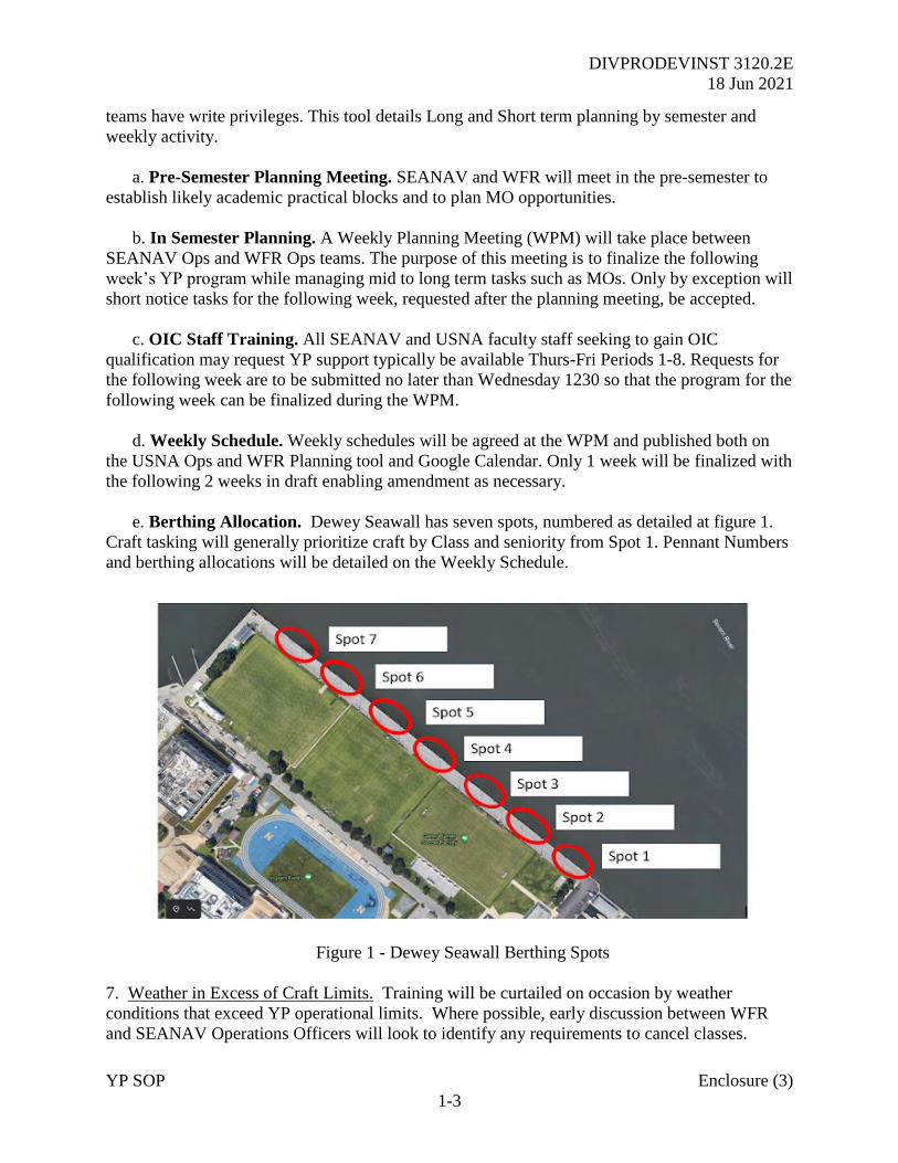
DIVPRODEVINST 3120.2E
18 Jun 2021
YP SOP Enclosure (3)
1-3
teams have write privileges. This tool details Long and Short term planning by semester and
weekly activity.
a. Pre-Semester Planning Meeting. SEANAV and WFR will meet in the pre-semester to
establish likely academic practical blocks and to plan MO opportunities.
b. In Semester Planning. A Weekly Planning Meeting (WPM) will take place between
SEANAV Ops and WFR Ops teams. The purpose of this meeting is to finalize the following
week’s YP program while managing mid to long term tasks such as MOs. Only by exception will
short notice tasks for the following week, requested after the planning meeting, be accepted.
c. OIC Staff Training. All SEANAV and USNA faculty staff seeking to gain OIC
qualification may request YP support typically be available Thurs-Fri Periods 1-8. Requests for
the following week are to be submitted no later than Wednesday 1230 so that the program for the
following week can be finalized during the WPM.
d. Weekly Schedule. Weekly schedules will be agreed at the WPM and published both on
the USNA Ops and WFR Planning tool and Google Calendar. Only 1 week will be finalized with
the following 2 weeks in draft enabling amendment as necessary.
e. Berthing Allocation. Dewey Seawall has seven spots, numbered as detailed at figure 1.
Craft tasking will generally prioritize craft by Class and seniority from Spot 1. Pennant Numbers
and berthing allocations will be detailed on the Weekly Schedule.
Figure 1 - Dewey Seawall Berthing Spots
7. Weather in Excess of Craft Limits. Training will be curtailed on occasion by weather
conditions that exceed YP operational limits. Where possible, early discussion between WFR
and SEANAV Operations Officers will look to identify any requirements to cancel classes.
DIVPRODEVINST 3120.2E
18 Jun 2021
YP SOP Enclosure (3)
1-4
SEANAV is to be made aware of any cancellation and the reason due to the impact on the
Academic schedule.
8. YP Casualty Management. YPs will routinely suffer material casualties prior to tasking.
However, clear communication is essential to minimize impact against planned tasking. In the
event of a casualty, the CM will liaise with the WFR Ops team via Senior CM, detailing the
Estimated Time to Repair (ETR). Where possible, a standby YP may be required to get
underway to support the scheduled task with a probable delay. In this case, WFR Ops will notify
the SEANAV Ops team who in turn will liaise with course coordinators to make them aware of
the impact.
9. YP Material State. The YPs, in particular the 676 Class, have been in service for a long time
and as such maintenance requirements naturally increase. However, because of the way in which
the YPs are operated, there is a danger of a culture in which we normalize deviation. This means
that common defects and casualties are simply accepted as a fact of daily life and normalized,
rather than driving defect reporting and management of rectification.
10. Individually, defects may have minimal impact against capability. Cumulatively however,
they can quickly add up to make a YP Non-Mission Capable. Therefore, it is important that all
OICs and CMs keep their eyes open towards defects and reporting. We must avoid a walk on by
culture where defects are simply accepted, especially where the result is a deviation of procedure
from the approved SOP.
11. WFR Operations will maintain a YP Material State board which details each individual
craft, and any reported material shortfalls. This can be used by OICs in advance of training, to
review their craft status. When conducting Out of Area Material Assessments, this should be
used as a basis for review, before the onboard inspection by OICs and Assessing Officers.
12. Minor defects should be reported to the CM on board. These should be then recorded for
submission to WFR Ops through the Underway Check Off list.
13. Major defects or casualties, especially where there is an assessed impact to capability or
safety, should be reported immediately to both the SEANAV and WFR Operations
organizations. WFR will then be responsible for the maintenance planning to rectify the issue,
and where necessary, any approvals that might be required from either SEANAV or the WFR
Director to proceed underway.
14. Civilian Guests on YPs Underway. Prior to hosting any Civilian guests onboard a YP
underway, approval must be obtained through SEANAV and WFR Ops with final approval by
Directors if required.
15. Before getting underway, civilians must complete a Service Craft Liability form as detailed
at Appendix A to Enclosure 3. This is to be retained by the CM and returned completed to WFR
Ops for all civilian personnel being embarked.
16. Points of Contact.

DIVPRODEVINST 3120.2E
18 Jun 2021
YP SOP Enclosure (3)
1-5
a. The WFR Point-of-Contact is Operations Officer, Waterfront Readiness or Senior Craft
Master.
b. The SEANAV Point-of-Contact is Operations Officer or Assistant Operations Officer,
Seamanship and Navigation.
DIVPRODEVINST 3120.2E
18 Jun 2021
YP SOP Enclosure (3)
2-1
CHAPTER 2
ROLES AND RESPONSIBILITIES OF SEANAV NAVIGATING OFFICER
References: (a) NAVDORM 2019
(b) DIVPRODEVINST 3150.E Yard Patrol Craft Standard Operating Procedures
1. Purpose. The management and administration of navigation planning, including route creation
and approval, is critical to the maintenance of navigational safety of Yard Patrol (YP) craft. A
nominated officer from within the Seamanship and Navigation (SEANAV) Department will
assume the role of Navigating Officer (NAV) to implement and oversee the formalization of
navigation procedures and standards across all YP operations.
2. Responsibility. The SEANAV Navigating Officer (NAV) is responsible to the SEANAV
Chairman for the oversight and management of navigation administration and routines for YPs
operating in the local area and deploying Out of Area (OOA).
3. Tasks. The SEANAV NAV is to implement and then manage the following routines:
a. Collate and maintain a library of SEANAV approved routes for local and deployed
operations.
b. Collate and maintain Gazetteers for the local operating area and key ports on the East
Coast.
c. Collate and maintain approved routes for local area operations, including channel
pilotage in the Severn River and approaches to nominated anchorages for training
purposes.
d. Supervise and work with the SEANAV Chart Room and WFR Operations Department to
ensure a Local Operations Folio of paper charts is available in all YPs, correctly drawn,
maintained, corrected and distributed in accordance with reference (b).
e. Supervise and work with the SEANAV Chart Room and WFR Operations Department to
ensure that the Voyage Management System (VMS) in the 676 Class and Raytheon
Pathfinder in the 703 Class are properly updated in accordance with reference (b).
f. Supervise and work with the SEANAV Chart Room and WFR Operations Department to
ensure that all digital and hard copy navigational publications and supporting equipment
requirements are updated and maintained in accordance with reference (b).
g. Supervise and work with Staff Navigators for Movement Orders (MOs) and Atlantic
Professional Training (LANTPAT) deployments OOA to ensure that new routes are
created in accordance with standards detailed at the references, prior to approval by
SEANAV.
DIVPRODEVINST 3120.2E
18 Jun 2021
YP SOP Enclosure (3)
2-2
h. Supervise and work with Staff Navigators and the SEANAV Chart Room to ensure
electronically approved routes are issued, and transferred correctly onto paper charts that
have been fully updated to the most recent Notice to Mariners (NTM) and Local NTMs.
i. To work with the SEANAV Divisional Officer (DIVO) and Chart Room personnel for
the implementation and sustainment of detailed administrative routines.
4. OOA Operations Route Approval. The following routine is to be implemented for OOA
operations route approval:
a. All navigation planning, including route and navigation aid planning, is to be created and
retained on a correctly updated VMS planning laptop. 3 Planning laptops, dual installed with
both VMS and Raytheon Pathfinder, are to be held and controlled by the SEANAV NAV. These
are to updated either monthly or as electronic chart updates are released.
b. Staff Navigators, including the YP Squadron (YPRON) Officer, are responsible for the
creation of any new routes for OOA operations. For training purposes, this task may be delegated
to Midshipmen, however the Staff Officer remains responsible for the proper oversight and
application of navigation planning procedures and standards. Once created, routes are to be
presented to the SEANAV NAV for checking prior to submission to SEANAV for electronic
plan approval.
c. Staff Officers are to identify the paper chart requirements associated with their routes.
Chart orders are to be then placed with the Chart Room, with a clear timeline provided of when
NTMs and LNTMs are to be applied. The SEANAV NAV is to be kept informed of chart
correction progress as required.
d. Once routes, with supporting gazetteers, are electronically approved by SEANAV, the
Staff NAV is to oversee transfer of Way Point (WP) information to paper charting, ensuring that
appropriate NTMs and LNTMs have been applied. Charts are to be prepared in accordance with
the standards detailed in reference (a) and the appropriate checklist in reference (b).
e. Once paper charts are correctly drawn, they require checking, approval and signature for
final authorization of the navigation plan by SEANAV.
f. Where OOA deployments are to be conducted on a 703 Class YP, route information may
be used to create a Raytheon Pathfinder ECDIS route. File conversion can be achieved with an
appropriate application. However, if unavailable, Way Points will have to be manually
transferred. In either case, WPs must be carefully checked for accuracy by the Staff NAV to
ensure paper and electronic navigation planning properly align.
6. SEANAV Route Catalogue. Wherever possible, approved routes are to be retained for future
operations to maximize SEANAV departmental efficiency. The following routines are to be
implemented and maintained:
DIVPRODEVINST 3120.2E
18 Jun 2021
YP SOP Enclosure (3)
2-3
a. Once a route is electronically approved by SEANAV, a copy of the VMS route file is to
be retained on the SEANAV NAV’s navigation planning laptop.
b. Routes developed on VMS should be converted to the Raytheon Pathfinder route format
and retained to enable future use on 703 Class YPs.
c. Route WP information is to be exported from VMS and retained in the SEANAV
Navigation Catalogue, to ensure future easy access and transfer to paper charting or to allow
reconstruction should a VMS route file be corrupted or lost. All such routes are to be catalogued
and maintained on the SEANAV Public Folder.
d. The paper chart requirement for approved routes is to be detailed and retained in the
SEANAV Navigation Catalogue with the most recent list of NTMs and LNTMs that should be
applied for each chart. This information can be found on the NOAA website at the link below.
e. A copy of approved paper charts should be retained in a Route Folio to enable updating
and copying for future use. Route paper folios are to be retained and overseen by the Chart
Room.
7. SEANAV Gazetteer Catalogue. For every route, there should be a list of supporting
navigation aids detailed in a Gazetteer. The following routines are to be implemented and
maintained:
a. VMS navigation layers are to be retained and submitted to the SEANAV NAV once
approved by SEANAV.
b. As part of navigation planning standards, a consolidated list of navigation aids is to be
created for ports, harbors or coastal areas using the format detailed in the SEANAV Navigation
Catalogue. Navigation aids are to listed by name, latitude and longitude, and where possible,
any other defining information such as light characteristics.
c. Wherever possible, photographs of prominent marks should be taken by Staff Navigators
for submission to the SEANAV NAV to aid future planning, identification and training during
OOA operations.
8. OOA Operation Planning. For the planning of any MOs, Staff Navigators are to initially refer
to the SEANAV NAV for direction and guidance. Where previous route information is available,
the following processes are to be implemented:
a. Where previously approved route information exists, the SEANAV NO will issue
information, including electronic route plans for VMS and Raytheon Pathfinder, WP information
for paper charting, and a supporting Gazetteer.
b. The SEANAV Navigation Catalogue will detail when each route was last utilized,
checked and approved. If approved by SEANAV within 12 months, the route remains approved.
However, the Staff NAV is to load the VMS route onto a properly updated planning laptop, to
DIVPRODEVINST 3120.2E
18 Jun 2021
YP SOP Enclosure (3)
2-4
ensure the plan remains valid and that no changes are required due to any issued NTMs or
LNTMs. If any changes are required, re-approval of the route is required.
c. Where a route has not be used within the last 12 months, the route is to be thoroughly
checked and re-approved electronically by SEANAV.
d. Once approved, the route may be transferred to paper charting. Where a paper route folio
not requiring amend is available, the paper charts should be updated for NTMs and LNTMs
before final check, signatures and copying.
e. In accordance with reference (b), the Staff Navigator is responsible for uploading
approved electronic routes to assigned Pennants and ensuring each craft carries sufficient copies
of paper charting.
f. On completion of the MO or OOA activity, electronic routes are to be removed from
VMS / Pathfinder to avoid confusion for future operations. Similarly, all paper charts, other than
those contained within the Local Area Folio, are to be removed and returned to the SEANAV
Chart Room.
g. An OOA Deployment Navigation Folder is to be prepared for each Pennant and its
content checked and approved by the SEANAV NAV. This folder is to contain as a minimum:
1) A printed copy of the approved Operation Order (OPORD).
2) A printed copy of the Navigation / Transit brief, including the Operational Risk
Matrix (ORM).
3) An authorized copy of the route’s paper chart list.
4) A list of all NTMs and LNTMs for each paper chart within the route folio.
5) A printed copy of all route WPs.
6) A printed copy of all Coastal Pilot chapters relevant to the route.
7) A printed copy of all tidal, current and ephemeral information.
h. The state of navigational planning and administration is to be carefully checked by
nominated Assessing Officers during OOA material and underway assessments.
9. OOA After Action Report (AAR). The AAR, to be submitted by the MO Officer in Tactical
Command, is to include any relevant navigation information to inform the SEANAV NAV of
any changes required to navigational planning. This should include an update on available
navigation aids, with supporting photos, to complement the existing gazetteer.
DIVPRODEVINST 3120.2E
18 Jun 2021
YP SOP Enclosure (3)
2-5
10. Local Operations Navigation Management. The SEANAV NO is to oversee the SEANAV
Chart Room for the provision and support of navigation administration in accordance with
reference (b). This is to include:
a. Provision of a Local Operations Folio, corrected to within 5 weeks for NTM and LNTM,
to be maintained and available in every YP.
b. Local Operations Folios are to include the following charts with the supporting approved
routes:
c. (List the 4 charts)
d. Provision of updated digital and hardcopy navigational publications in accordance with
reference (a).
e. Oversight and support to the Chart Room for ensuring SEANAV Planning Laptops are
updated electronically on a monthly basis.
f. Oversight and support to the Chart Room and WFR Operations for ensuring all YPs
ECDIS / VMS are updated on a monthly basis.
11. Training. The SEANAV NAV is to support SEANAV and WFR Training Officers in the
provision of periodic training to ensure YP Officers in Charge (OICs) and Craft Masters (CMs)
are able to implement and uphold the navigational standards detailed in this instruction, in
addition to the references.
DIVPRODEVINST 3120.2E
18 Jun 2021
YP SOP Enclosure (3)
A-1
APPENDIX A TO ENCLOSURE 3
SERVICE CRAFT LIABILITY
EVENT: ___________________________ DATE OF EVENT: _______________________
In consideration of my request to tour/embark a Yard Patrol craft or other Naval Academy vessel, I, the undersigned, as well as my minor children, intending to be legally bound, hereby waive myself, parents, guardians, heirs, executors, assigns, and administrators any and all rights and claims for damages, demands, and other actions whatsoever, including that which I may have against any of the following entities: United States Naval Academy, Annapolis, Maryland; Department of the Navy; Department of Defense; United States Government; all United States Naval Academy military and civilian personnel; as well as all participating supporters and personnel provided; and these entities’ representatives, successors, and assigns, arising out of my participation in this event, including any and all injuries or illnesses suffered by me as a result of my participation in this event or use of any United States Naval Academy or government facilities, equipment, or vessel in conjunction with my participation. I further verify I have full knowledge of the risks involved in participation in events of this nature where marine craft are used.
I agree to the site of any lawsuit and the law governing any such lawsuit shall be governed under the Federal Tort Claims Act, Military Claims Act, Foreign Claims Act, Suits in Admiralty Act, Public Vessels Act or Admiralty Extension Act, whichever is applicable. The terms of this agreement shall continue and be in effect after this activity has ended. I hereby give permission for transportation to any medical facility or hospital and I authorize any staff member, or medical personnel to render necessary emergency medical care for my family or me. I hereby authorize the release of any medical information, including information concerning my HIV or “AIDS” status, in the possession of Naval Academy personnel to any medical facility, hospital, ambulance, first aid provider, first aid service, doctor, nurse or other such person rendering care on my behalf. I hereby waive any action or claim against the Naval Academy, the Department of the Navy, and the Department of Defense, and its staff or any health care provider, hospital, doctor, nurse or first aid provider for the release of this medical information including my HIV or “AIDS” status.
I authorize and release the Naval Academy, the Department of the Navy, the Department of Defense, the United States Government, and all United States Naval Academy personnel and staff the use of my name or likeness and image in any photograph or video recording for any purpose whatsoever.
I also understand that I am responsible for my conduct while aboard the naval vessel to which I am assigned. I am further aware that no alcoholic beverages of any type are allowed aboard any Navy marine craft, and any misuse of equipment or its facilities will result in revocation of my privileges to participate in this or any future marine event at the United States Naval Academy.
Additionally, I understand if I cannot swim, it is in my best interest to wear a Type III U.S. Coast Guard approved personal flotation device (PFD) at all times while onboard Navy vessels. If Under Age 18: I, the understood parent or lawful guardian of the below-named person, do hereby grant my permission and consent for my child to participate in the above-described event. I have read and agree to be bound by the above-mentioned terms. I understand my child must be

DIVPRODEVINST 3120.2E
18 Jun 2021
YP SOP Enclosure (3)
A-2
at least 8 years of age and must have a Type III U.S. Coast Guard PFD on the day of the events.
NAME: _____________________________________
SIGNATURE (or parent/guardian signature if under age 18):
_______________________________________ DATE: _________________