Embed Size (px)
Citation preview
DIVISION 26 00 00 ELECTRICAL
January 22, 2019 Page 1 of 12
26 05 00 Electrical Common Work 1. Symbols
1.1. All drawings submissions, regardless of the phase of the project, shall have a legend of all symbols used in the drawing.
2. Floor Plans and Riser Diagrams 2.1. Building floor plans shall accurately represent the architectural as-built conditions.
2.2. Electrical systems and equipment shall be illustrated showing major conduit/wireway
locations, equipment, receptacles, lighting, communications systems, security systems, fire alarm, emergency lighting and power on appropriate layers as defined in the General Section of Queen’s Building Design Standards.
2.3. Riser diagrams shall be provided for all major systems and shall conform to Queen’s
standard arrangements, showing equipment by floor levels.
3. Record Drawings and Maintenance Manual This section should be read in conjunction with section 01 70 00 Close-Out Requirements. 3.1. Records drawing shall include, are not limited to:
• Campus digital map will indicate all underground services (if applicable) • 5kV power distribution operating diagrams (if applicable) • Building floor plans illustrating major conduit runs, locations of equipment, proper
equipment identification, circuit numbers • Fire, security, and normal/emergency power system riser diagrams
3.2. Manufacturer’s catalogue data, equipment schedules, panel schedules, panel
summaries, warranties, certificates, verification and test reports, spare parts, short circuit, coordination, and arc flash study, operating and maintenance instructions shall be provided at the end of the project.
4. Identification of Equipment 4.1. Paint in yellow “KEEP CLEAR AT ALL TIMES” for working space around electrical
equipment as required by the latest revision of the Ontario Electrical Safety Code. In locations where this is not practical, high visibility labels shall be affixed to the equipment.
4.2. All equipment including panels, transformers, network switches, disconnect devices, safety switches, control equipment etc., shall be labelled with white lamacoid nameplates using black engraved lettering for normal-powered equipment, and red
DIVISION 26 00 00 ELECTRICAL
January 22, 2019 Page 2 of 12
lamacoid nameplates using white engraved lettering for emergency-powered equipment.
4.3. Nameplates shall be permanently secured in place with screws and/or PPS approved adhesive.
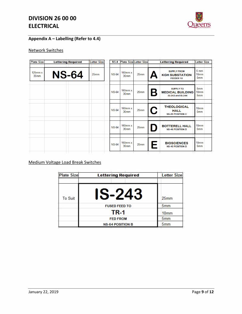
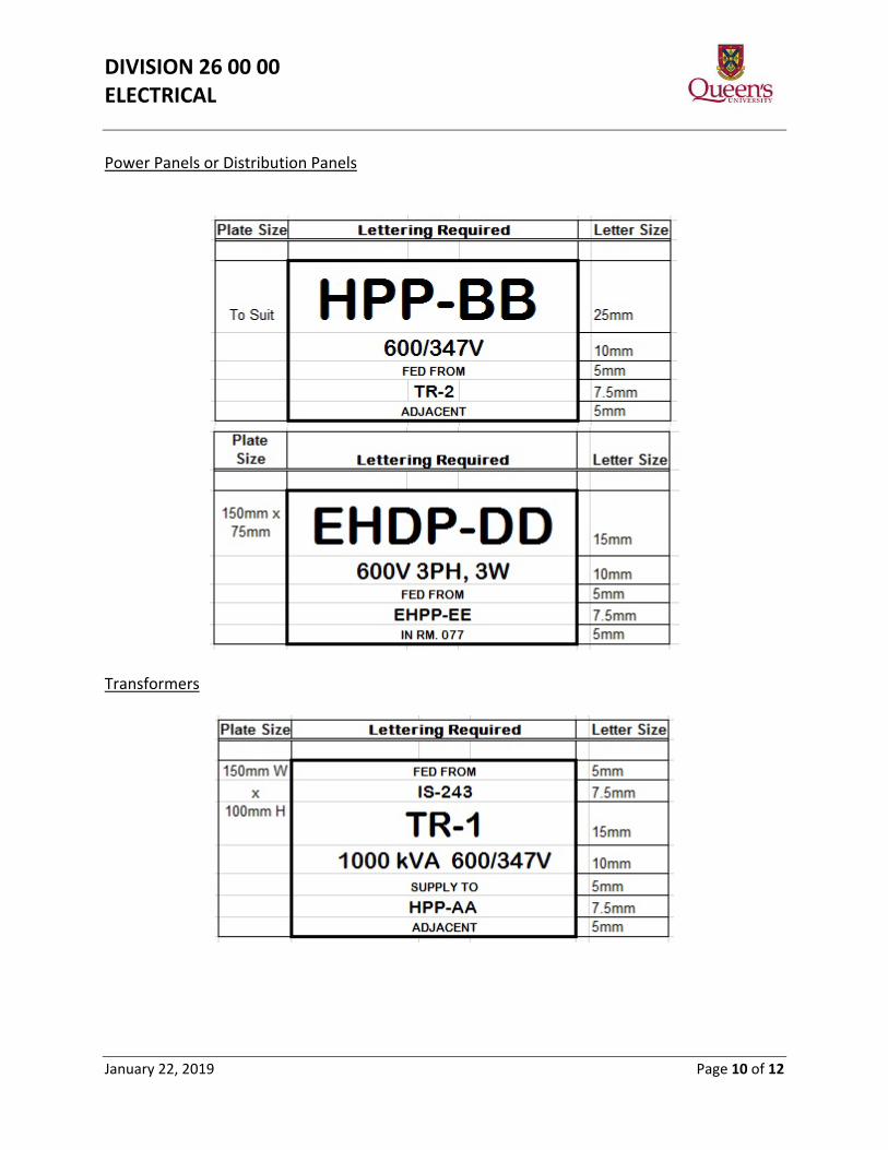
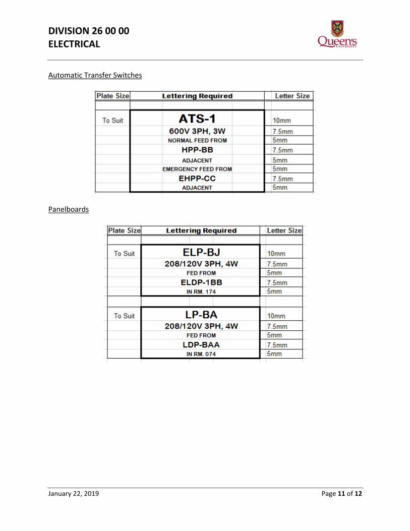
4.4. Nameplates shall include all pertinent information such as equipment designation,
voltage of panel, no. of phases/wires, and where panel is fed from and location of feeder panel. See Appendix A at the end of the section for examples of lamacoid design.
4.5. The following abbreviations and numbering schemes shall be used:
Abbreviation Equipment Description NS (5kV) Medium Voltage Network Switch IS (5kV) Isolation Switch (Fused or Non-Fused) TR Transformer HPP 600V (High Voltage) Power Panel in Vault LPP 208V (Low Voltage) Power Panel in Vault HDP 600V (High Voltage) Distribution Panel LDP 208V (Low Voltage) Distribution Panel HP 600V (High Voltage) Panelboard LP 208V (Low Voltage) Panelboard MCC Motor Control Centre HSP 600V (High Voltage) Splitter (Panel or Trough) LSP 208V (Low Voltage) Splitter (Panel of Trough)
4.6. Prefix “E” shall be added to any of the abbreviations to designate “Non-Life Safety
Emergency” power when fed from a standby generator or central inverter system, i.e. EHP = Emergency High Voltage (600V) Panel; and prefix “EX” shall be added to any of the abbreviations to designate “Life Safety Emergency” power fed from a standby generator i.e. EXLPP = Life Safety Emergency Low Voltage Power Panel.
4.7. Suffixes shall be provided for each abbreviation used as follows: 4.7.1. Main Switchboards, Power Panels, Distribution Panels and Splitters shall be
assigned double letters in sequence i.e., HPP-AA, LDP-BB, LSP-CC.
4.7.2. Branch circuit panel boards shall be assigned alphanumeric suffixes with floor level and single letter in sequence i.e., LP-1A, HP-1B, ELP-1C, LP-2A, EHP-2B.
4.8. Receptacles on emergency power shall be red in colour.
DIVISION 26 00 00 ELECTRICAL
January 22, 2019 Page 3 of 12
4.9. A sticker indicating the source panel and circuit number shall be placed on all receptacles.
5. Electrical Interference 5.1. The use of electronic, low voltage devices in research and teaching is increasing. To
avoid interference, electrical fixtures and equipment should be electrically “quiet” and non-arcing.
5.2. Harmonics generated by equipment shall have no deleterious effect on the distribution system or other building equipment.
6. Equipment Housekeeping Pads 6.1. Install base mounted equipment on chamfered edge housekeeping pad: minimum 4”
high, minimum 2” larger than equipment dimensions all around. 7. Wiring Methods
7.1. Wiring shall be installed in conduit to facilitate changes, i.e. increasing wire gauge, adding circuits, repairing damaged wiring etc. Where practical, conduit shall be oversized to accommodate such change.
7.2. Connection to equipment subject to vibration/movement (such as motors) shall be flexible conduit.
7.3. Lighting circuits shall be wired in conduit except final drops may be made with type
AC90 cable. No runs of type AC90 cable shall exceed 3 meters in length.
7.4. Provide a separate (minimum #12 AWG) green insulated ground wire in all conduits and raceways.
7.5. The use of isolated grounding systems is strongly discouraged.
7.6. Main electrical distribution shall be solidly grounded.
7.7. All branch circuits are to be stranded type.
7.8. Label all wires in junction boxes as well as at terminations.
7.9. Where 347V and 120V lighting is in the same space, they shall be clearly marked as
such, and easily identifiable.
8. Conduit 8.1. Conduit shall be adequately sized with room for fifteen percent more wire in general
areas and fifty percent in lab and research areas.
DIVISION 26 00 00 ELECTRICAL
January 22, 2019 Page 4 of 12
8.2. No more than three ¼ bends (or equivalent) shall be allowed in any conduit run
between pull points.
8.3. Conduit shall be Electrical Metallic Tubing (EMT) electro-plate steel where code permits; Electrical non-metallic Tubing (ENT) embedded in concrete is acceptable in most applications.
8.4. Aluminum conduit may be used provided that the alloy used conforms to Canadian
Standard Association (CSA) standards and provided that it is not embedded in concrete.
9. High Voltage Power Cables and Terminations – 15kV 9.1. The main campus power grid comprises a 4,160V distribution system utilizing 15,000V
(minimum) insulated phase conductors with insulated bonding conductor.
9.2. New services will require evaluation of the network to establish interconnection requirements. New power cables may be 500 MCM AWG single conductor concentric neutral, XLPE-TR insulated or 500 MCM AWG single conductor, tape shield, XLPE-TR insulated. If tape shield is to be used, a separate 4/0 AWG bonding conductor shall be installed. All cables are to be copper conductor and have 133% insulation level.
9.3. 15kV Termination shall be 3M Cold Shrink QT-III or approved equivalent and 15kV
splices shall be 3M Cold Shrink QS-III or approved equivalent. Splices will be kept to a minimum and shall be installed in accessible, preferably dry locations.
10. Wire and Cables (0-1000V) 10.1. All branch wiring shall be copper conductor, #12AWG minimum. Feeder cables shall
XLPE rated at 90◦C. Building wiring may be XLPE or TWH. A separate insulated ground conductor shall be installed in all conduit systems.
10.1.1. The following colour code shall be used: Ground: Green Neutral: White Phase A: Red Phase B: Black Phase C: Blue Low voltage wiring: Brown
11. Wiring Devices 11.1. Preferred manufacturers are Hubbell, Bryant, Arrow Hart, Pass & Seymour and
Leviton. Stainless steel cover plates are preferred.
11.2. Occupancy sensors and vacancy sensors may be proposed.
DIVISION 26 00 00 ELECTRICAL
January 22, 2019 Page 5 of 12
11.3. Manufacturer’s catalogue cuts including specifications are required for wiring devices provided.
12. Short Circuit Rating 12.1. Devices added to existing equipment (ie. panelboard, switchboard, MCC) shall have a
minimum short circuit rating of the existing equipment.
12.2. Devices shall be specification grade “heavy duty”.
13. Connection and Terminations 13.1. Wiring connectors that enable the connection to be inspected, before the insulation
is applied, are preferred such as MARR connectors with socket-type screws or compression type connectors such as the Buchanan connectors.
13.2. All power cable terminations shall be of the compression fitting type such as Thomas
& Betts 54100 series, Burndy Hylugs, or Burndy UNITAP Multiple Tap Connector (clear/insulated).
14. System Short Circuit, Co-ordination, and Arc Flash Studies 14.1. A short circuit, co-ordination, and arc flash study shall be provided for all protective
devices and equipment in the electrical distribution system in co-operation with suppliers of all pertinent equipment. Any short circuit, co-ordination, and arc flash problems shall be resolved or brought to the attention of PPS Engineering for resolution. Arc flash labels will be provided by the company performing the study.
14.2. A copy of the short circuit, co-ordination, and arc flash study shall be included in the
Maintenance Manual.
15. Bus Duct and Other Flexible Systems 15.1. Special permission must be given by PPS for bus duct or other flexible system.
16. Padlocks for Electrical Switchgear 16.1. Switchgear that is energized, that requires a lock, shall be padlocked with the
standard electrical Master Padlock with key number X2286.
16.2. Network switches shall have each Test Position Access normally locked open using the standard Master padlock with key number X2286.
16.3. Switchgear that, in the open position, defines an open point in the distribution
system shall be locked open using the standard Master lock padlock with key number 2233.
DIVISION 26 00 00 ELECTRICAL
January 22, 2019 Page 6 of 12
16.4. Switchgear access doors requiring restricted access shall be locked using the 2233 padlock.
16.5. Padlocks shall be manufactured by Master Lock Company. They shall have a 44mm
wide (1 ¾”) laminated brass body and hardened steel shackle 8mm (5/16 ”) diameter; 19mm (¾”) horizontal clearance; 38mm (1 ½ “) vertical clearance. Padlock shall be complete with protective bumper, precision 4 pin tumbler locking mechanism and number stamped into padlock base.
16.6. Acceptable products: Master Padlock catalogue numbers – 2KALF to key X2286 and
2KALF to key 2233. 17. Electrical Equipment Rooms
17.1. Access to electrical equipment rooms shall be limited to authorized personnel. Entrance doors shall be marked according to latest revision of Ontario Electrical Safety Code.
17.2. Door locks shall be keyed to Medeco J1 for electrical rooms containing >750V and
Medeco JB for electrical rooms containing <750V. In some cases a padlock hasp shall be provided, padlock to be supplied by PPS.
17.3. Provide copper ground bus around entire main electrical room and connect to all
electrical switchgear (if required by Ontario Electrical Safety Code).
17.4. Main electrical equipment rooms shall be sized to provide room and cable entrance space for (up to) a six pole network switch and include room to expand the number of SKV load break switches as well as the secondary distribution panel.
17.5. The layout of electrical equipment rooms shall be reviewed and approved by PPS.
17.6. The main electrical room of a building shall be above grade and easily accessible to replace equipment in future.
17.7. Design Checklist for electrical equipment rooms: 1. Location
• Facilitate major electrical equipment replacement/repair (electrical room at grade and double door access)
• Avoid proximity of water (pipes, sumps) • Minimize noise transmission to adjacent spaces • Level of electrical room floor must be above all sewage/sump pits
2. Ventilation • Isolated • Adequate to control temperature
DIVISION 26 00 00 ELECTRICAL
January 22, 2019 Page 7 of 12
• Supply and exhaust • Minimum noise • Mechanical cooling when required (in addition to supply and exhaust fan system)
3. Access • Key specified by Operations Department
4. Protection • Fire Detection (Photo Electric Smoke Detector preferred) • Fire Suppression may be considered but electrical equipment must be sprinkler-proof
5. Lighting • Lighting to be switched • Emergency - battery operated (only if no standby power or if standby power
equipment in room i.e. ATS, generator, etc.) or on standby power • Adequate lighting on standby power (if possible) so that equipment maintenance can
be performed when no utility power.
6. Emergency • Provide Emergency Receptacle(s) if standby power is available
7. Signage • In accordance with latest revision of Ontario Electrical Safety Code and Queen’s
Signage Policy • Single Line Distribution Diagram to be framed, posted
8. Grounding • In accordance with code requirements
9. Records • Accurate As-Built Drawings
18. Electric Vehicle Chargers 18.1. Install minimum four (4) electric vehicle chargers as part of the construction of a new
building or an entire building renovation if parking nearby. In all cases, make certain electrical service size accommodates a minimum of four (4) electric vehicle chargers.
19. Motors 19.1. All motors shall be of energy efficient design. 19.2. All motors shall have life seal lubricant ball bearings. 19.3. Motors up to but not including 3/4HP may be single phase 120V. However, fractional
horsepower motors that are required to start and stop frequently shall be three phase.
DIVISION 26 00 00 ELECTRICAL
January 22, 2019 Page 8 of 12
19.4. Division 22/23 (Mechanical) often provides motors for pumps, fans, air conditioners etc. The specifications for these motors and controls must be coordinated with Division 26 and meet all requirements of Division 26.
19.5. Motors to be controlled by variable frequency drives shall be inverter-duty rated. (i.e.
Class F insulation (min.)) 19.6. All motorized equipment shall be designated with maintenance identification
supplied by PPS Operations/Engineering.
19.7. Documentation shall include motor nameplate data, catalogue cuts and specification sheets.
DIVISION 26 00 00 ELECTRICAL
January 22, 2019 Page 9 of 12
Appendix A – Labelling (Refer to 4.4) Network Switches
Medium Voltage Load Break Switches
DIVISION 26 00 00 ELECTRICAL
January 22, 2019 Page 10 of 12
Power Panels or Distribution Panels
Transformers
DIVISION 26 00 00 ELECTRICAL
January 22, 2019 Page 11 of 12
Automatic Transfer Switches
Panelboards
DIVISION 26 00 00 ELECTRICAL
January 22, 2019 Page 12 of 12
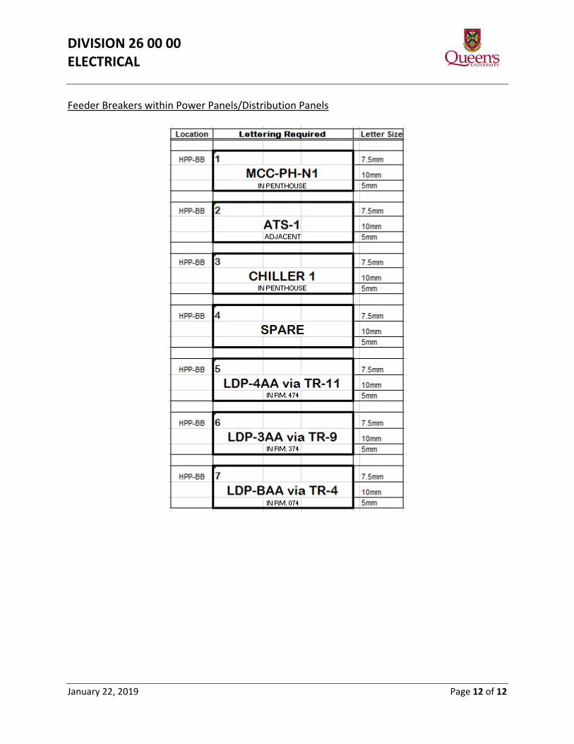
Feeder Breakers within Power Panels/Distribution Panels