Embed Size (px)
Citation preview

WINSTA-RDistal Radius System


WINSTA-R
Page 1
Introduction WINSTA-R System 2 Indication 2
Surgical Technique Palmar Access for Radius Plate 3 Dorsal Access for Radius Plate 3 Positioning of the Radius Plate 4 Fixation of the Plate in the Slide Hole 4 Distal Screwing 5 Insertion of ML Screws 7 Proximal Screwing 8 Access Ulna Plate & Ulna Hook Plate 9 Positioning of the Ulna Plates 9 Product Information Implants 10 Instruments 14
Notes 15
Note:The surgery instructions outlined below reflect the surgical procedure usually chosen by the clinical consultant. However, each surgeon must decide individually which course of action offers the best chance of success in the individual case.
▶ Table of Contents

WINSTA-R
Page 2
▶ Introduction
WINSTA-R System
• High stability with small implant dimensions.• Use of multiaxial screws / buttress pins (ML Screws / ML Buttress Pins) with a deflection of ± 10 ° from the normal
position permits high variability in the fixation of fragments, with minimal screw head protrusion.• The special surface anodisation according to type II reduces the tendency to cold welding between plate and screw. In
addition, the hardness of the titanium surface is significantly increased by this process, and significant reduction in the release of aluminium and vanadium is noted.
• Rounded plate profile for optimal soft tissue protection.• Simple and ergonomically designed instrument set with only one Ø-2.0-mm drill bit provides a high level of safety and
security for the surgeon and the surgical staff.• The locking buttress pins allow quick fixation of the fragments to the plate.
Indication
• Extra-articular fractures of AO-Type 23-A2 and A3• Partial intra-articular fractures of AO-Type 23-B1 and B3• Total intra-articular fractures of AO-Type 23-C1 to C3
WINSTA-R Distal Radius Plates
• The WINSTA-R System consists of several plates with anatomically correct shape for reconstruction of the “palmar tilt”, taking into account the Watershed Line.
• Additional dorsal support of the articular surface and the dorsal edge fragment via the second row of screws.• Locking plates for palmar and dorsal treatment.
WINSTA-R Distal Ulna Plates
• Anatomically preformed plates, side-specific for the right and the left ulna.• Plate versions with and without distal hook.• Plates with distal hooks for better fixation of the ulnar styloid process.
Indication
• Fixation of capital and sub-capital fractures of the distal ulna.

WINSTA-R
Page 3
▶ Surgical Technique
2. Dorsal access for radius plate
• Dorsally, create a longitudinal incision over the distal radius, between the 2nd and 3rd dorsal extensor tendon compartment.
• Perform a longitudinal incision between the 1st and 2nd extensor tendon compartment to expose the extensor retinaculum.
• For easier access to the fracture site, carefully lift the 3rd extensor compartment (extensor pollicis longus), mobilise it proximally and distally and relocate it radially.
• Lift the second dorsal tendon compartment subperiostally radially and the fourth dorsal tendon compartment subperiostally ulnarly, to preserve the integrity of the compartments.
1. Palmar access for radius plate
• On the palmar side, a straight skin incision parallel to the fle-xor carpi radialis tendon is created.
• Take care not to hurt the arteria radialis on the radial and the nervus medianus on the medial side.
• Detach the pronator quadratus on the radial side from the radial shaft.
Note:• In case of multifragmentary involvement of the joint fragment,
the fragments should be left associated to facilitate ligamentotaxis.

WINSTA-R
Page 4
3. Positioning of the radius plate
•While applying tension to the fingers and in palmar flexion of the wrist, reduce the fracture until the joint fragment abuts against the distal end of the plate.
• In the event of a dorsal fragment zone it can be helpful to apply dorsal pressure onto this zone with one finger while filling the distal plate holes; this will ensure the retention of the fragments through the stabilising screw/pins inserted in anatomical position.
• Attention must be paid to correct reduction of the fracture.• Once the fracture has been reduced into an anatomically
correct position, the plate is fixed temporarily with Kirschner wires in the distal and proximal areas.
4. Fixation of the plate in the slide hole
InstrumentsREF 10.20010.020 Drill Bit Ø 2.0 mmREF 11.90012.150 Kirschner Wire Ø 1.2 mmREF 12.20060.017 Double Drill Guide 2.0 / 1.7
• The slot is filled with a cortical screw Ø 2.7 mm.• The screw hole is pre-drilled using the drill bit via the double
drill guide.
InstrumentsREF 03.20100.040 Depth Gauge for Screws, range 40 mm
• Subsequently, the required screw length is determined using the depth gauge.

WINSTA-R
Page 5
InstrumentsREF 03.20040.030 Screwdriver, hex 2.5 mm
• After the required screw length has been determined, the ap-propriate cortical screw can be inserted with the screwdriver.
• The screw is initially tightened only slightly, so that the plate position can be corrected distally and proximally as required.
• Check the plate position once more and correct it, if necessa-ry, with image amplifier monitoring.
• Once the plate position is correct, the screws are finally tigh-tened, and the plate is thus fixed on the radius shaft.
InstrumentsREF 03.20100.040 Depth Gauge for Screws, range 40 mmREF 10.20010.0xx Guide Block
• Alternatively, for determining the required screw length a depth gauge can be used.
• The depth gauge is placed directly on the plate, and after hooking onto the opposite cortex, the value can be read.
• If a guide block is used, the depth gauge can be placed through the guide block onto the plate, and the screw length can be determined.
5. Distal screwing
InstrumentsREF 10.20010.020 Drill Bit Ø 2.0 mmREF 10.20060.047 Drill Sleeve 2.0REF 10.20010.0xx Guide Block
• For locking cortical screws of Ø 3.0 mm, the scaled drill slee-ve is screwed into the screw hole to be filled.
•When the drill bit is used, the required screw length can be read directly on the scale of the drill sleeve.
• To be able to insert the drill sleeve in a guided manner into the predefined screw angles, optionally the guide block can be used.

WINSTA-R
Page 6
InstrumentsREF 03.20040.030 Screwdriver, hex 2.5 mmREF 10.20010.0xx Guide Block
• After determination of the required screw lengths, the locking cortical screws are screwed in using the screwdriver.
• Cortical screws should be placed prior to insertion of locking cortical screws.
• The drill holes for the locking cortical screws should be crea-ted only when the cortical screws are tightened. Otherwise, the plate position relative to the bone may slightly change, causing the drilling axes not to match exactly anymore.
• If a guide block is used, the locking cortical screw can be inserted through the guide block into the screw hole.
InstrumentsREF 10.20060.047 Drill Sleeve 2.0REF 10.20100.050 Depth Gauge for Screws, range 50 mmREF 10.20010.0xx Guide Block
• There is the option of measuring with the depth gauge over the drill sleeve.
• For this purpose, the depth gauge, which is marked by a dot, is placed on the drill sleeve after this has been screwed in.
Use of locking buttress pins
• The fixed-angle support pins allow quick and persistent fixa-tion of the reduction achieved. Due to the tensile forces on the forearm, the flexors clearly dominate, always creating a resultant force that pulls the fragments against the plate and onto the pins.
• It is advisable first to fill one of the two central holes of the distal row.
• Subsequently, the other holes should be filled with pins or screws.
Force component of the flexors
Force component of the extensors
Resulting force

WINSTA-R
Page 7
InstrumentsREF 03.20040.030 Screwdriver, hex 2.5 mm
• The locking buttress pins can likewise be inserted into the drill hole using the screwdriver and locked in the plate at a fixed angle.
6. Insertion of ML Screws
InstrumentsREF 03.20100.040 Depth Gauge for Screws, range 40 mmREF 10.20010.020 Drill bit Ø 2.0 mmREF 10.20050.025 ML Drill Guide 2.0REF 10.20010.0xx Guide Block
• For ML screws Ø 2.7 mm, the ML drill guide is used. The funnel-shaped drill guide is screwed into the corresponding screw hole and allows stepless multiaxial drilling in a cone of 20 °.
• To screw the ML drill guide more quickly into the plate, optio-nally the guide block can be used.
• The screw length is determined using the depth gauge (see item 5).
20°
Note:• The range of 20° must not be exceeded, since otherwise cor-
rect locking between screw and plate cannot be guaranteed.

WINSTA-R
Page 8
InstrumentsREF 03.20040.030 Screwdriver, hex 2.5 mm
• The ML buttress pins can likewise be inserted into the drill hole using the screwdriver and locked in the plate at a fixed angle.
7. Proximal screwing
• Here the procedure for inserting the proximal locking cortical screws corresponds to item 4.
•When all screw holes are filled, a final radiographic control is performed.
InstrumentsREF 03.20040.030 Screwdriver, hex 2.5 mmREF 10.20010.0xx Guide Block
• After determination of the required screw lengths, the ML screws are screwed in using the screwdriver.
• If a guide block is used, the ML screw can be inserted through the guide block into the screw hole.

WINSTA-R
Page 9
8. Access ulna plate & ulna hook plate
• Create a longitudinal incision over the palpable ulna.• Take care not to hurt the dorsal branch of the ulnar nerve.• After the distal ulna has been exposed, dissect subperio-
stally, expose the fragments and reduce them.• Carefully hold back the dorsal branch of the ulnar nerve.• In order to facilitate the insertion and positioning of the ulna
hook plate, notching of the capsular tissue at the level of the radial styloid processus with two parallels incisions is helpful.
9. Positioning of the ulna plates
Distal Ulna Hook Plate:
• Expose and reduce the fracture.• The reduced fracture and the plate can be temporarily fixed
by means of Kirschner wires.• Place the hooks of the ulna hook plate around the tip of the
ulnar styloid process as a reference for positioning. • Then position the plate on the subcutaneous edge of the dis-
tal ulna and fixate in both the head and shaft.• The distal ulna hook plate is fixated as described above with
cortical screws, locking cortical screws or ML screws. • Final radiographic control.
Distal Ulna Plate:
• Expose and reduce the fracture.• The reduced fracture and the plate can be temporarily fixed
by means of Kirschner wires.• First, fill the long hole with a cortical screw Ø 2.7 mm as de-
scribed in item 4.• Then fixate the plate in the head and shaft areas as described
above.• Final radiographic control.
WINSTA-R
Page 10
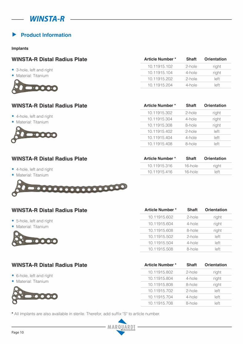
WINSTA-R Distal Radius Plate
• 5-hole, left and right•Material: Titanium
Article Number * Shaft Orientation10.11915.602 2-hole right10.11915.604 4-hole right10.11915.608 8-hole right10.11915.502 2-hole left10.11915.504 4-hole left10.11915.508 8-hole left
▶ Product Information
Implants
Article Number * Shaft Orientation10.11915.302 2-hole right10.11915.304 4-hole right10.11915.308 8-hole right10.11915.402 2-hole left10.11915.404 4-hole left10.11915.408 8-hole left
WINSTA-R Distal Radius Plate
• 4-hole, left and right•Material: Titanium
WINSTA-R Distal Radius Plate
• 3-hole, left and right•Material: Titanium
Article Number * Shaft Orientation10.11915.102 2-hole right10.11915.104 4-hole right10.11915.202 2-hole left10.11915.204 4-hole left
WINSTA-R Distal Radius Plate
• 6-hole, left and right•Material: Titanium
Article Number * Shaft Orientation10.11915.802 2-hole right10.11915.804 4-hole right10.11915.808 8-hole right10.11915.702 2-hole left10.11915.704 4-hole left10.11915.708 8-hole left
Article Number * Shaft Orientation10.11915.316 16-hole right10.11915.416 16-hole left
WINSTA-R Distal Radius Plate
• 4-hole, left and right•Material: Titanium
* All implants are also available in sterile. Therefor, add suffix "S" to article number.

WINSTA-R
Page 11
WINSTA-R Dorsal Radius Plate
• 5-hole, left and right•Material: Ti6Al4V
Article Number * Shaft Orientation10.11916.302 2-hole right10.11916.304 4-hole right10.11916.402 2-hole left10.11916.404 4-hole left
WINSTA-R Distal Radius Plate
• 7-hole, left and right•Material: Titanium
Article Number * Shaft Orientation10.11917.002 2-hole right10.11917.004 4-hole right10.11917.102 2-hole left10.11917.104 4-hole left
WINSTA-R Distal Ulna Hook Plate
• 6 and 8-hole, left and right•Material: Ti6Al4V
Article Number * Shaft Orientation10.11918.006 6-hole right10.11918.008 8-hole right10.11918.106 6-hole left10.11918.108 8-hole left
WINSTA-R Distal Ulna Plate
• 7-hole, left and right•Material: Ti6Al4V
Article Number * Shaft Orientation10.11918.007 7-hole right10.11918.107 7-hole left
* All implants are also available in sterile. Therefor, add suffix "S" to article number.

WINSTA-R
Page 12
Cortical Screw Ø 2.7 mm,self-tapping
• Thread diameter: 2.7 mm• Core diameter: 1.9 mm• Head diameter: 5.0 mm• Hexagon socket: 2.5 mm•Material: Ti6Al4V
Article Number * Length03.03527.010 10 mm03.03527.012 12 mm03.03527.014 14 mm03.03527.016 16 mm03.03527.018 18 mm03.03527.020 20 mm03.03527.022 22 mm03.03527.024 24 mm03.03527.026 26 mm03.03527.028 28 mm03.03527.030 30 mm03.03527.032 32 mm03.03527.034 34 mm03.03527.036 36 mm
ML Screw Ø 2.7 mm,self-tapping
• Thread diameter: 2.7 mm• Core diameter: 1.9 mm• Head diameter: 4.75 mm• Hexagon socket: 2.5 mm•Material: Ti6Al4V
Article Number * Length03.03540.008 8 mm03.03540.010 10 mm03.03540.012 12 mm03.03540.014 14 mm03.03540.016 16 mm03.03540.018 18 mm03.03540.020 20 mm03.03540.022 22 mm03.03540.024 24 mm03.03540.026 26 mm03.03540.028 28 mm03.03540.030 30 mm03.03540.032 32 mm03.03540.034 34 mm03.03540.036 36 mm
ML Buttress Pins Ø 2.0 mm
• Core diameter: 2.0 mm• Head diameter: 4.75 mm• Hexagon socket: 2.5 mm•Material: Ti6Al4V
Article Number * Length10.03560.016 16 mm10.03560.018 18 mm10.03560.020 20 mm10.03560.022 22 mm10.03560.024 24 mm10.03560.026 26 mm10.03560.028 28 mm10.03560.030 30 mm
* All implants are also available in sterile. Therefor, add suffix "S" to article number.

WINSTA-R
Page 13
Locking Buttress Pins Ø 2.0 mm
• Core diameter: 2.0 mm• Head diameter: 4.75 mm• Hexagon socket: 2.5 mm•Material: Ti6Al4V
Article Number * Length10.03520.016 16 mm10.03520.018 18 mm10.03520.020 20 mm10.03520.022 22 mm10.03520.024 24 mm10.03520.026 26 mm10.03520.028 28 mm10.03520.030 30 mm
Locking Cortical Screw Ø 3.0 mm,self-tapping
• Thread diameter: 3.0 mm• Core diameter: 1.9 mm• Head diameter: 4.75 mm• Hexagon socket: 2.5 mm•Material: Ti6Al4V
Article Number * Length10.03530.008 8 mm10.03530.010 10 mm10.03530.012 12 mm10.03530.014 14 mm10.03530.016 16 mm10.03530.018 18 mm10.03530.020 20 mm10.03530.022 22 mm10.03530.024 24 mm10.03530.026 26 mm10.03530.028 28 mm10.03530.030 30 mm10.03530.032 32 mm10.03530.034 34 mm10.03530.036 36 mm
* All implants are also available in sterile. Therefor, add suffix "S" to article number.

WINSTA-R
Page 14
Instruments
10.20010.020 Drill Bit Ø 2.0 mm, 2-flute, AO-Coupling, L 112 / 84 mm
11.90012.150 Kirschner Wire Ø 1.2 mm, trocar tip, L 150 mm, stainless steel
03.20100.040 Depth Gauge for Screws, range up to 40 mm
10.20100.050 Depth Gauge for Screws, range up to 50 mm, for REF 10.20060.047
12.20060.017 Double Drill Guide 2.0 / 1.7
10.20060.047 Drill Guide 2.0, calibrated
03.20040.030 Screwdriver, hex 2.5 mm, ball handle, L 200 / 85 mm
02.20120.015 Screw Forceps, self-holding
03.20040.026 Holding Sleeve for Screws Ø 2.7 - 4.0 mm
10.20050.025 ML Drill Guide 2.0
10.20010.040 Guiding Block for 6/2; 6/4; 6/8 hole WINSTA-R plate, right
10.20010.050 Guiding Block for 6/2; 6/4; 6/8 hole WINSTA-R plate, left
10.20010.045 Guiding Block for 5/2; 5/4; 5/8 hole WINSTA-R plate, right
10.20010.055 Guiding Block for 5/2; 5/4; 5/8 hole WINSTA-R plate, left

WINSTA-R
Page 15
▶ Notes

WINSTA-R
Page 16
▶ Notes


Dieter Marquardt Medizintechnik GmbH
Robert-Bosch-Str. 1 - 78549 SpaichingenTelefon: +49 (0) 7424 / 95810 - Telefax: +49 (0) 7424 / 501441
leas
e da
te: 0
9.02
.201
7; 1
0.99
100.
002;
Rev
.: 00
2/00