Embed Size (px)
Citation preview

AutoPlus Operation Manual
60-200-802 Rev. D, ECO 1751
DATE: 01AUG2005
Hanson Research Corporation
9810 Variel Avenue Chatsworth, CA 91311 USA
(800) 821-8165 (818) 882-7266 FAX (818) 882-9470 www.hansonresearch.com
2005 Hanson Research Corporation.
This product is covered under one or more of the following US Patents: 3,572,648 4,108,602 4,274,286 5,198,109 5,296,139 5,639,953 5,639,974 5,682,001 6,006,777 6,076,410 6,422,098 6,821,419 B2 Des.377,152 Des.424,458 & Other Patents Pending.

(this page intentionally left blank)

Auto Plus Operation Manual 60-200-802-D
Table of Contents i
Table of Contents
What’s New ______________________________________________________ iv
1 Safety Considerations ___________________________________________ 1
1.1 General ___________________________________________________________ 1
1.2 Safety Markings ___________________________________________________ 1
1.3 Canadian Emissions Notice __________________________________________ 2
2 Introduction ____________________________________________________ 3
2.1 Definitions ________________________________________________________ 3
2.2 General ___________________________________________________________ 4
2.3 How the System Works _____________________________________________ 4
2.4 Tubing Volume Calculations _________________________________________ 5
2.5 Firmware Revisions ________________________________________________ 5
3 Specifications __________________________________________________ 7
4 Installation _____________________________________________________ 9
4.1 Location __________________________________________________________ 9
4.2 Unpacking and Inspection __________________________________________ 10
4.3 Identification _____________________________________________________ 11
4.4 Installation and Electrical Connections _______________________________ 12
4.5 Communication Connections _______________________________________ 13
4.6 Liquid Connections _______________________________________________ 14
4.7 Start Up _________________________________________________________ 15
5 Operation and Programming _____________________________________ 16
5.1 Keypad Description _______________________________________________ 16
5.2 Screen Icons _____________________________________________________ 18
5.3 Indicator Lights ___________________________________________________ 18
5.4 Power Up and Main Screen _________________________________________ 18
5.5 Use of Scrolls ____________________________________________________ 19
5.6 Selecting an Input _________________________________________________ 20
5.7 Input of Alphabetical Characters _____________________________________ 20
5.8 Manual Operation _________________________________________________ 22
5.9 System Options __________________________________________________ 23

Auto Plus Operation Manual 60-200-802-D
Table of Contents ii
5.10 System Alarms / Timers __________________________________________ 29
5.11 Clock Options __________________________________________________ 31
5.12 Print Options ___________________________________________________ 31
5.13 Selecting and Viewing Protocol Parameters __________________________ 32
5.14 Creating a New Protocol __________________________________________ 32
5.15 Editing a Protocol _______________________________________________ 34
5.16 Viewing Protocol Parameters ______________________________________ 34
5.17 Working with Scripts _____________________________________________ 35
5.18 Running a Test __________________________________________________ 39
5.19 Starting a Protocol _______________________________________________ 39
5.20 Standby Mode __________________________________________________ 41
6 Running A Test ________________________________________________ 42
6.1 Setting Up _______________________________________________________ 42
6.2 Starting and Running a Test ________________________________________ 43
6.3 During the Test ___________________________________________________ 43
6.4 After the Test _____________________________________________________ 43
7 Section Seven – Troubleshooting _________________________________ 44
7.1 Contacting Hanson Research Corporation for Technical Support _________ 44
7.2 Troubleshooting Table _____________________________________________ 44
8 Section Eight – Maintenance and Calibration _______________________ 47
8.1 Maintenance Schedule _____________________________________________ 47
8.2 General Cleaning _________________________________________________ 47
8.3 Cleaning Method for Tubing, Valves and Syringes ______________________ 47
8.4 Fuse Replacement ________________________________________________ 48
8.5 Syringe Replacement ______________________________________________ 48
8.6 Volume Calibration ________________________________________________ 49
8.7 MultiFill Needle Replacement _______________________________________ 49
8.8 MultiFill Belt Replacement __________________________________________ 49
9 Section Nine – Moving and Storage _______________________________ 51
9.1 Storage __________________________________________________________ 51
9.2 Moving __________________________________________________________ 51

Auto Plus Operation Manual 60-200-802-D
Table of Contents iii
10 Service Parts ________________________________________________ 52
11 Sales and Support ____________________________________________ 53
12 General Warranty _____________________________________________ 54

Auto Plus Operation Manual 60-200-802-D
What‟s New iv
What’s New
Revision D Wetted materials for 91-601-270 Check Valve revised in Section 3 (ECO 1751).
AutoPlus Firmware version 3.12 added to Firmware Revision Log in Section 2 (ECO 1756).

AutoPlus Operation Manual 60-200-802-D
Section 1 Safety Considerations
– 1 –
1 Safety Considerations
1.1 General
1. The installation category (overvoltage category) for this instrument is Level II. The Level II category pertains to equipment that receives its electrical power from a local level, such as an electrical wall outlet.
2. This instrument must be connected to a grounded electrical outlet.
3. Never work on the electrical components in the system while there is power to the unit. Disconnect power before servicing the instrument.
4. Review all safety and environmental precautions pertaining to any chemicals that are to be used in conjunction with this equipment.
1.2 Safety Markings
For your own safety, you must observe the following safety warning markings. The safety warning markings indicate a possible source of danger. At the same time they contain information on how correct action can avert danger. You will always find safety warning markings attached to points of possible danger.
Sign Location Safety Warning
N/A
Attention: This is a highly sensitive instrument. Read the operation
manual before using the AutoPlus System. When you use the system, follow generally accepted procedures for quality control and methods development. Attention: Changes or modifications to the components that comprise
the Hanson AutoPlus System that are not expressly approved by the party responsible for compliance could void the user‟s authority to operate the equipment. Attention: This equipment has been tested and found to comply with
the limits for a Class A digital device, pursuant to Part 15 of the FCC rules. These limits are designed to provide reasonable protection against harmful interference when the equipment is operated in a commercial environment. This equipment generates, uses, and can radiate radio frequency energy, and, if not installed and used in accordance with the operation manual, may cause harmful interference to radio communications. Operation of this equipment in a residential area is likely to cause harmful interference, in which case you must correct the interference at your own expense. Shielded cables must be used with this unit to ensure compliance with the Class A FCC limits. Attention: To meet the regulatory requirements of immunity from
external electrical disturbances that may affect the performance of this instrument, do not use cables longer than 9.8 feet (3 meters) when you make connections to the terminal strips on the rear panels of the components of the AutoPlus System. Also, always connect the shield of the cable to chassis ground at one instrument only.

AutoPlus Operation Manual 60-200-802-D
Section 1 Safety Considerations
– 2 –
Sign Location Safety Warning
N/A Power Supply Rear Panel Left Side (next to screw)
Caution: To avoid chemical or electrical hazards, always observe safe
laboratory practices when operating the AutoPlus System. Caution: Supply voltage and supply frequency must be of the value
specified on the back of the power supply. All electrical outlets must be properly grounded. Caution: Supply voltage and wattage must be of the value specified for
the control unit in the serial number tag located on the back of the control unit. All electrical outlets must be properly grounded. Caution: Turn instrument off and remove power cord before replacing
fuse. Fuse must be replaced with the same current rating and type described next to the fuse holder. Caution: No operator accessible parts inside. Refer servicing to
qualified personnel only. Achtung: Es gibt keine vorn Benutzer zo wanenden Teile.
Oberlassen Sie Reparaturen dem qualifizierten Service-fachmann. Attention: Aucune pièce remplaçable par l‟utilisateur. Toute
réparation doit être effectuée par un technicien qualifié. Precaución: No lo abra. Peligro de alto voltaje. El servicio debe ser
implementado por personal calificado.
Rear Main Board Panel
Caution: Communication ports must not be connected to a telephone
line.
Inside Control
Protective conductor terminal.
Rear Panel
Direct current.
1.3 Canadian Emissions Notice
This digital apparatus does not exceed the Class A limits for radio noise emissions from digital apparatus set forth in the Radio Interference Regulations of the Canadian Department of Communications.
Le présent appareil numérique n‟émet pas de bruits radioélectriques dépassant les limites applicables aux appareils numériques de la classe A prescrites dans les réglements sur le brouillage radioélectrique édictés par le Ministére des Communications du Canada.

AutoPlus Operation Manual 60-200-802-D
Section 2 Introduction
– 3 –
2 Introduction
2.1 Definitions
AutoPlus™ The basic autosampler series (either Maximizer or DissoScan) with stepper motor driven syringes.
Maximizer™ The autosampler with 4 two-way solenoid valves per syringe to direct fluid flow. (see Figure 4-2)
DissoScan™ The autosampler with 1 three-way solenoid valve per syringe to direct fluid flow. (see Figure 4-2)
MultiFill™ The instrument that allows for sample collection. (see Figure 4-3)
Load The drawing of material into the syringe by the syringe plunger.
Dispense The pushing out of material from the syringe by the syringe plunger.
Rack The vial / test tube holder that fits on the MultiFill.
Valve The device that controls flow direction.
Prime The filling of an empty tube with selected material.
Rinse The clearing out of old media from tubing with the target media.
Wash The clearing out of old media from tubing with blank or wash media.
Transfer The moving of liquid from one tube to another.
Dilute The collection of two different materials in the same test tube.
Protocol The parameters that are entered into the instrument that determine the operation and steps that are to be accomplished for a given test.
Generic A bath that is not an SR8-Plus or a ValiData control.
Auto-Probe™ The automatic moving of sample probes.
Fixed Probe A stationary sampling probe.
Occurrence The dictated time at which a function is performed.

AutoPlus Operation Manual 60-200-802-D
Section 2 Introduction
– 4 –
2.2 General
NOTE: It is recommended to read the entire operation manual before installing or operating this equipment.
The AutoPlus is a programmable autosampler that handles a wide variety of dissolution applications and requirements.
On command it withdraws by means of precision stepper motor drive and a syringe, measures, and dispenses an aliquot from a dissolution test station through a UV flow cell and further into a collection rack that contains vials or test tubes. The AutoPlus can repeat this process multiple times.
Most other commercial dissolution sampling systems use peristaltic pump movement of dissolution fluid into a collector or through a UV flow cell. The AutoPlus was developed to avoid the volumetric inconsistency and high maintenance of the peristaltic pump and provide an all inert type environment to minimize drug absorption (see Section 3—Specifications for wetted materials)
1. Basic autosamplers (Model MX6 or DS6) will sample from 6 distinct sources. (Model MX8 or DS8) will sample from 8 distinct sources.
2. If sample collection is needed, using the Hanson MultiFill allows the operator to program sample volume collection into a variety of test tube and vial sizes. Note that all septums and caps must be pre-cut.
3. The Validation Printer allows the user to utilize the full feature of the AutoPlus printing capabilities. Protocol parameters, plus the time, speed and temperature at the start of the test and each time a bath is sampled are also logged when a Validation Printer is added to the system. Note that bath condition printing can only be done when the unit is connected with a Hanson SR8-Plus Dissolution Test Station.
2.3 How the System Works
1. A valve at the top of each syringe opens. The stepper motor turns, driving the syringe plunger down to the desired volume, loading material into the syringe.
2. The first valve closes and another valve opens. The stepper motor reverses direction to drive the syringe plunger up, pushing the contents out of the syringe and on to a new location.
3. The AutoPlus can be connected to a multiple flow cell spectrophotometer for online UV/VIS analysis. It can also be connected to a MultiFill collector for sample archiving.
4. The Maximizer can replace media removed from the dissolution vessel. After the sampling cycle is completed, the unit can automatically replace the media that was taken from the dissolution vessel.
5. When using only one bath, the AutoPlus can cycle all unused sample back to the vessel, eliminating any wasted sample.

AutoPlus Operation Manual 60-200-802-D
Section 2 Introduction
– 5 –
6. When using more than one bath, rinse volume is sent to waste. Baths are sampled one at a time, usually 3 to 5 minutes apart.
7. Samples may be collected into the MultiFill. Samples may also be diluted while in the MultiFill.
2.4 Tubing Volume Calculations
1/32” ID (1/16” OD Teflon® or stainless steel tubing) = 0.0126mL per inch.
0.085” ID (1/8” OD stainless steel tubing) = 0.093mL per inch.
2.5 Firmware Revisions
Hanson Research Corporation is constantly working to improve our products and to help our customers comply with regulatory requirements. The information below is a history of software (firmware) changes for the AutoPlus.
Version 3.12
Enhanced MultiFill communications.
Improved scripting performance.
Version 3.10
User is automatically logged out when power is turned off.
Improved Syringe Default Settings.
Version 3.0
Security— This new feature allows up to 25 names to be added to a list which contains users with Manager or Operator privileges. Managers can change system parameters and protocols. Operators can only view the system parameters and view/run the protocols.
Password Protection— When password protection is enabled from the security menu, the system requires that a valid user log into the system and that the correct password associated with that user be entered before any system function is allowed. Password protection helps the user comply with the 21CFR regulations.
System Setup Traceability— Whenever any of the system setup parameters is changed or a maintenance routine is performed, the action is stamped with the date, time and username.
Protocol Traceability— When protocols are created or edited, they are stamped with the date, time and username.
Inactivity Log Out— When password protection is enabled, the system will automatically log out the current user after a period of inactivity. This period is programmable.
Print Last Test Feature— Everything that is sent to the printer during the test is now stored in memory until the next test. It may be printed if the printer fails (paper, ribbon, mechanical) during the test.
Prestart— The AutoPlus can now be programmed to prestart its sampling routine by a programmed time to accommodate tight timing specifications.
Auto Pill Dropper— AutoPlus now sends automatic pill drop signal to SR8-Plus Dissolution Test Station.

AutoPlus Operation Manual 60-200-802-D
Section 2 Introduction
– 6 –
Configurable Header Titles— Titles printed at the beginning of a report have been expanded to 8 and can be edited by the system manager.
Configurable Protocol Titles— Information Items in protocols can now be edited by the system manager to customize protocols.
International Date Formats— The system allows the manager to select one of four date formats for printing, displaying, and stamping dates.
Screen Icons— New screen icons graphically show password protection status, printing options, availability of revision logs, and multiple screens.
Scripting— Added a new scripting function to allow the user to send closed contact signals and serial commands to an external device.
Protocol Navigation Improved— The number of screens required to view/edit a protocol has been reduced for easier navigation.
Improved Diagnostics— Diagnostics has been improved so that readiness of all peripherals connected to the system is assured.
Improved Help— The help system has been revised so that virtually every screen has a help window associated with it.
Version 1.02
Added functionality of retrieval reservoir.
Version 1.01
Added control of SR8-Plus E-Probe.
Added auto-recovery after a power failure.
Version 1.00
Initial Release.

AutoPlus Operation Manual 60-200-802-D
Section 3 Specifications
– 7 –
3 Specifications
Weight: AutoPlus: ...................................................................................................... 16 kg (36 lb) MultiFill: ........................................................................................................ 22 kg (49 lb)
Size: AutoPlus Width: ......................................................................................................... 25 cm (9.5 in) Depth: ....................................................................................................... 50 cm (19.5 in) Height: .................................................................................................... 37 cm (14.25 in)
Size: MultiFill Width: ......................................................................................................... 25 cm (9.5 in) Depth: .......................................................................................................... 66 cm (26 in) Height: ...................................................................................................... 40 cm (15.5 in)
Electrical: AutoPlus Voltage: ................................................................................ 100 to 240 VAC, Grounded Frequency:......................................................................................................... 50/60 Hz Power Dissipation: ............................................................................................. 30 Watts Phase: .................................................................................................................... single Fused at:............................................................................................. 3 amp (“TT” Type)
Electrical: MultiFill Voltage: ............................................................ 115 VAC or 230 VAC ± 10%, Grounded Frequency:......................................................................................................... 50/60 Hz Power Dissipation: ............................................................................................. 20 Watts Phase: .................................................................................................................... single Fused at:...................................................... 3 amps 115 VAC / 1.6 230 VAC (“F” Type)
Environment:
Ambient Temperature Range: ..............................................................................4-40°C
Maximum Humidity: ............................................................................................... < 85% Altitude:………………………………………………………………………….Up to 2000 m Installation Category II Pollution Degree 2 Indoor use only
Interface Equipment Requirements:
SR8-Plus: ....................................................................................... Version 3.0 or higher ValiData ......................................................................................................... Version 2.2 Sampling Probes: ......................................................... HRC-style sampling probes only Printer: ................................................................................... HRC validation printer only

AutoPlus Operation Manual 60-200-802-D
Section 3 Specifications
– 8 –
Sample Volume Accuracy:
0.5 to 5.0mL: ...................................................................................................... 0.05mL
5.1 to 10.0mL: .................................................................................................... 0.10mL
10.1 to 15.0mL:.................................................................................................. 0.15mL
Materials, Wet: AutoPlus Syringes:......................................................................... Borosilicate Glass and Teflon® Sample Tubing: ................................................................................................... Teflon® Ferrules: ................................................................................................. Tefzel® (ETFE) Valves and Manifold: ................................ PEEK™ and Ethylene Propylene Elastomers
Materials, Wet: MultiFill Injection Needles: ............................................... Polycarbonate and 304 Stainless Steel Transfer Valves: ........................ PEEK™, Teflon® and Ethylene Propylene Elastomers Check Valves:......................................................................... Polypropylene and Viton®
Filtration 10 micron Tip Filter: ....................................................................... at Sample Probe Inlet 5 micron, 25mm luer type ........................................................... at Sample Probe Outlet
Sampling: Minimum1 sample interval: ...................................................................................... 1 min Maximum sample interval: ........................................................................... 99 hr, 59 min Number of programmable sampling points:............................................................ 1 - 40 Number of sampling collections before rack change: ............................................21 / 24 Maximum2 sample volume: ......................................... 90% of Vial / Test Tube Capacity Collection Rack Type: .......................... 8 x 21 Rows 168 Total 16 x 100 mm Test Tubes Collection Rack Type: ...................................... 8 x 24 Rows 192 Total 12 x 32 mm Vials Vial / Test Tube Size: .......................................................... 12 x 32 mm or 16 x 100 mm Septum: ...............................................................................................Pre-cut Type Only
1 Under specified conditions.
2 One sample time point may be collected in multiple rows.

AutoPlus Operation Manual 60-200-802-D
Section 4 Installation
– 9 –
4 Installation
4.1 Location
4.1.1 Environmental Requirements
The AutoPlus should be placed to the right of the first dissolution bath and between the first and second bath. The Hanson MultiFill should be placed under or to one side of the AutoPlus. (See Section 3 for requirements.)
4.1.2 Space Requirements
Figure 4-1: Typical System Layout
The AutoPlus is designed to be placed on a standard laboratory bench that is at least 60 cm (24 in) deep. The system requires clearance above the bench of at least 66 cm (26 in)—see waterbath, spectrophotometer, and computer manufacturers specifications for the exact requirements of their components. The laboratory bench should be level and flat. The laboratory bench must also be capable of supporting the weight (see Section 3—Specifications). When using three baths, the system layout requires an island layout with a width of about 130 cm (50 in). Make sure to have at least this amount of space. (See Section 3 for requirements.)
4.1.3 Electrical Requirements
The AutoPlus requires a single, grounded electrical outlet, within 2.5 m (8 ft) of the location of the system.
The AutoPlus is available in one configuration, 100V through 240V. The voltage is automatically set when voltage is supplied to the external power supply.
The MultiFill is available in two configurations, 115V and 230V. The voltages are set at the factory by changing the fuse box configuration. Check the nameplate on the back panel to ensure the unit is set to the correct voltage.
Mu
lti-F
ill
SR8-Plus "B"A
uto
+SR8-Plus "A"
Spectro
Computer
SR8-Plus "C"Spectro
Computer
Pri
nt
30 60 90 120 150 18030 060120 90180 150
0
30
60
90
120
150
Centimeters
AutoPlus Operation Manual 60-200-802-D
Section 4 Installation
– 10 –
The printer is available in different configurations depending on system set-up and requirements. The printer will be electrically connected to either the SR8-Plus or directly into a power outlet. Check the nameplate on the side panel to ensure the unit is the correct voltage.
NOTE: Power cords may need to be replaced for some countries‟ power outlet configurations. Ensure replacement power cord is approved and properly rated for voltage and amperage.
4.2 Unpacking and Inspection
The AutoPlus is shipped in one or more boxes. The shipping boxes are specifically designed to provide maximum shipping protection and to facilitate unpacking.
1. The AutoPlus, spare parts kits, and accessories are packed in individual custom fit enclosures and then placed into crate size boxes. Carefully unpack your AutoPlus from its shipping cartons.
2. Check the contents of the carton against the shipping list to be sure that you have unpacked the entire shipment.
3. Inspect each unit for damage and, if any is evident, inform the shipping company immediately. It is also wise to save the shipping cartons as evidence in case of damage. Hanson Research Corporation insures all shipments through the shipping company, but is not responsible for shipping damages.
To unpack the system:
1. Move package close to final destination.
2. Cut and remove any straps.
3. Open box, taking care not to damage box.
4. Remove instrument(s) from box.
5. Reassemble empty box and store for possible future use.

AutoPlus Operation Manual 60-200-802-D
Section 4 Installation
– 11 –
4.3 Identification
Throughout this manual, reference is made to various components by name. Figures are provided to assist in the visual identification of these components.
BATH / PRINTER
1
PC
COMM PORTS
SPECTRO
3
COLLECTOR
2 4 AUX I/O
abc
stu
vwx
jkl
mno
def
yz()
pqr
ghi
Figure 4-2: Maximizer / Dissoscan
Multi-Fill Ready
Figure 4-3: MultiFill

AutoPlus Operation Manual 60-200-802-D
Section 4 Installation
– 12 –
4.4 Installation and Electrical Connections
1. After removing the instrument from the box, remove all other shipping materials.
2. Visually inspect the instrument(s) for damage or missing parts. Immediately notify Hanson Research of any discrepancies.
3. Remove any strapping or tape holding the unit for shipping.
4. Clean the unit as necessary to remove any packing debris.
5. Visually inspect all electrical and liquid connections for shipping damage.
6. Review operation manual.
NOTE: The instrument should not be plugged in until installed per the following instructions.
First decide if you are going to place the AutoPlus on top of the MultiFill.
1. MultiFill
MultiFill installation is done by first placing the unit on the bench. With the power switch in the off position, plug the power cord into a grounded wall outlet. Plug the other end of the power cord into the connector on the right side of the unit.
2. Collection Rack
Installing the collection rack is done by first checking the location pin on the front left of the MultiFill base. Make sure it is set to the rack size you are using. Set the collection rack on the center of the MultiFill while aligning the hole under the collection rack with the location pin on the base of the unit.
3. AutoPlus
The AutoPlus installation is done by placing the AutoPlus on top or to the right of the MultiFill. With the power switch in the off position, connect its power supply cord into the small round connector labeled "power input" on the back of the unit and slide the cord into the bracket that hangs down under the round connector; this will ensure that the cord is not pulled out. With the power switch in the off position, plug the power cord into a grounded wall outlet. Plug one end of the power cord into the side of the power supply.
4. Printer
The printer may be placed on top of AutoPlus if the AutoPlus is not going to be placed on top of the MultiFill. Plug the power cord into either a grounded wall outlet or to a Hanson Dissolution Test Station (see the operation manual for the dissolution test station used).

AutoPlus Operation Manual 60-200-802-D
Section 4 Installation
– 13 –
5. Dissolution Test Station(s)
The dissolution test station(s) should be placed to each side of the AutoPlus, with the “A” bath to the left and the “B” bath to the right. (See the operation manual for the dissolution test station used for proper installation instructions.)
4.5 Communication Connections
Spectro
SR8-Plus "B"
Computer
Multi-Fill
#3
SR8-Plus "A"
#1
#1#2
Printeror
#3
Auto-Plus#4
#1
#2
SR8-Plus "C"#2 #1
or
#3 #3
or
Figure 4-4: Communication Connections
Each communications cable (grey cable with same type of plug at each end) is inserted into the corresponding socket by just pushing in. You will hear a click when correctly installed. To remove, depress the tab and pull straight out.
All equipment should be in place at this time.
1. AutoPlus to MultiFill
Connect AutoPlus to MultiFill. The MultiFill will use the lower “D” connector type plug on the left side of the MultiFill along with the communications cable. The connection is done from the back of the AutoPlus #3 to this connector.
2. AutoPlus to Hanson Dissolution Test Station or Printer
Connect the communications cable from #2 on the back of the AutoPlus to #1 on the first Hanson Dissolution Test Station. When not using Hanson Dissolution Test Station(s), connect #2 on the back of the AutoPlus to the bottom of the printer. Note that the first Hanson Dissolution Test Station connected to the AutoPlus is bath “A”, the second is bath “B” and so on.

AutoPlus Operation Manual 60-200-802-D
Section 4 Installation
– 14 –
3. Hanson Dissolution Test Station to Hanson Dissolution Test Station
For each Hanson Dissolution Test Station, connect from #2 to #1 with the last Hanson Dissolution Test Station connecting to the printer. Note that the first Hanson Dissolution Test Station connected from the AutoPlus is bath “A”, the second is bath “B” and so on.
4. AutoPlus to Spectrophotometer / Computer
Connect from AutoPlus #4 to the spectrophotometer and AutoPlus #1 to a computer if using these devices. (See other reference and operation manuals supplied with this system to make final connections to these devices.)
5. Other Dissolution Test Station
Install and connect the dissolution instrument per the manufacturer‟s recommendations. There is no communication with non-Hanson Dissolution Test Stations.
4.6 Liquid Connections
1. Liquid Line Connections
Liquid line connections are done by connecting the six or eight liquid tubes from the AutoPlus, MultiFill, spectrophotometer and sampling probe. These are numbered and color coded for identification (see Figure 4-6). They are connected with nuts, unions and ferrules, as shown in Figure 4-5. Tighten these fittings by hand only—do not use tools.
UNIONNUT FERRULE
Figure 4-5: Liquid Line Connections
Position Fitting Color
1 Black
2 Red
3 White
4 Yellow
5 Green
6 Blue
7 Clear
8 Purple
Table 4-6: Liquid Connection Color Codes

AutoPlus Operation Manual 60-200-802-D
Section 4 Installation
– 15 –
Figure 4-7: Overall Liquid Connections
There are many ways to connect the dissolution system. Follow the options shown in Figure 4-7. Make sure to connect number to number. Route tubing in a way to keep it out of the way and safe from moving parts. Be careful never to set any equipment on top of the tubing. Tubing harnesses are supplied to make liquid connections. If the tubing is not long enough to make it to a destination, add another tubing harness to extend the overall harness length. The shortest length of tubing is always preferred and will reduce the rinse volume requirement.
4.7 Start Up
NOTE: The voltage indicated on the control unit must be the same as the power source. If the incorrect voltage is indicated, do not plug in the instrument; contact Hanson Research immediately.
1. Turn on the power switch located on the front panel of the AutoPlus. The display will
come on and you will hear the stepper motor home itself and then stop.
2. Turn the power off.
3. Verify that the voltage indicated on the back of the MultiFill is the same as the power source.
4. Turn on the power switch, located on the right side panel of the MultiFill. The display should come on and you will hear the stepper motor home itself and leave the needles in the up position. The display will show “MultiFill Ready”.
5. Turn the power off.
NOTE: If any of these steps did not work as described, return to the beginning of the installation section and check all connections, then refer to Section 7—Troubleshooting.
SR8-Plus "C"SR8-Plus "A" SR8-Plus "B"
Media
ReplaceMultiple
StandardsWaste
Auto-PlusSpectroMulti-Fill
"D"In Out In
or
or
or
or
or
"C"
"B"
"A"
or
"Return"

AutoPlus Operation Manual 60-200-802-D
Section 5 Operation and Programming
– 16 –
5 Operation and Programming
5.1 Keypad Description
Figure 5-1: AutoPlus Keypad
Key Key Name Use
Run The first press of this key allows the user to select a stored protocol. The second press of this key starts the selected protocol.
Syringe Control This key gives the user access to syringe functions to perform pre-run priming and post-run cleaning functions.
Source Control This key gives the user access to functions that deal with the sources connected to the AutoPlus for pre-run and post-run setup tasks.
System Options This key is used to access a series of options. These include contrast adjustment for the LCD display, validation and calibration options, password protection, diagnostics, and system configuration.
Edit/View Protocol This key is used to select the parameters for a new protocol. This key is also used to edit/view the parameters of a stored protocol. Password is required to change parameters.
Print Options This key is used to access print options. These include: print status, print protocol, print header, and configure header title.

AutoPlus Operation Manual 60-200-802-D
Section 5 Operation and Programming
– 17 –
Stop This key is used to abort a test in progress. Press twice to abort test. If this key is pressed when there is no test in progress, the system is placed in the standby mode.
Clock This key is used to access the clock and alarm options. These include setting real time and date, display 12HR/24HR clock, sampling alarm, user alarms, calibration alarm, and alarm acknowledgment.
Help This key is used to access the help screens for the system. The AutoPlus has context-sensitive help screens. These include: unit operation tips, calibration tips, and maintenance.
Navigation Keys These keys are used to move up, down, to the right and to the left.
Figure 5-2 Navigation Keys
Esc Key This key is used to backup to the previous screen.
Enter Key This key is used to select an entry.
Clr Key This key is used to erase or delete an entry.

AutoPlus Operation Manual 60-200-802-D
Section 5 Operation and Programming
– 18 –
5.2 Screen Icons
These icons are located on many system screens. Their purposes are:
Clock Press to view the current revision for that setting.
Printer Press to print the current screen information.
Lock Open Indicates that the security system is enabled and that a manager is logged on.
Lock Closed Indicates that the security system is enabled and that an operator is logged on.
Figure 5-3: Screen Icons
5.3 Indicator Lights
Power On This light indicates power is supplied to the system.
Diagnostics An energized light indicates the system detects a fault, which is fatal to its use.
Timer Alert An energized light indicates an alarm has been activated. This light turns off automatically whenever the alarm is acknowledged.
5.4 Power Up and Main Screen
Whenever the system is powered up, a Title screen is displayed for a few seconds and then the Main screen is displayed, as shown in Figure 5-4.
0:00
0:00
Figure 5-4: Main Screen
Notice that there are three tabs on the Main screen: Status, Set Point, and Header. These are the three screens that comprise the Main screen. In Figure 5-4, the Status screen is
displayed. Press [ ] and/or [ ] to display the other screens. The Status screen is normally displayed when the system is operating. In most cases, if one of the Main screens is not displayed, it can be displayed by pressing [Esc] one or more times.

AutoPlus Operation Manual 60-200-802-D
Section 5 Operation and Programming
– 19 –
5.5 Use of Scrolls
The user selects the desired input to operating parameters using a scroll. An example of a scroll is shown in Figure 5-5.
Figure 5-5: Example Scroll
If the desired input for the parameter is displayed in the scroll, press [ ] and/or [ ] to highlight it and press [ENTER]. The scroll shows up to five inputs. Each time an input is selected, it is placed at the top of the scroll.
If the desired input is not displayed, key in the input and press [ENTER]. The input is placed at the top of the scroll and highlighted. If the scroll is full with five inputs, the input at the bottom of the scroll is deleted or moved off the edge of the display and the new input is placed at the top of the scroll. If the input is moved off the edge, simply arrow down to view the input. Press [ENTER] to accept the highlighted input.
Press [CLR] to delete the highlighted input, if necessary.
Some parameters, such as the Sampling Times shown in Figure 5-6, require numeric input. Other parameters, such as the user's name, require alphabetic input. Input of alphabetical characters is described later in this section.
Figure 5-6: Numeric Inputs

AutoPlus Operation Manual 60-200-802-D
Section 5 Operation and Programming
– 20 –
5.6 Selecting an Input
An example of a scroll which requires alphabetical characters is shown in Figure 5-7. To
display this screen, activate the Status screen and then press [ ], [ ] to display the Header screen. Press [0] to display the input screen for "User Name". Highlight the desired operator name and press [ENTER].
NOTE: This example assumes that password protection is disabled.
Figure 5-7: Alphanumeric Scroll
5.7 Input of Alphabetical Characters
An example of a screen which requires an input of alphabetical characters is shown in Figure
5-8. To display this screen, activate the Status screen and then press [ ], [ ] to display the Header screen. Press [1] to display the "Operator Name" input screen. If the desired operator's name is highlighted on the scroll, it can be selected as described above (see 5.6).
Figure 5-8: Header Screen
AutoPlus Operation Manual 60-200-802-D
Section 5 Operation and Programming
– 21 –
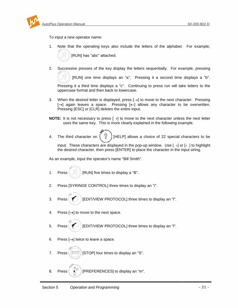
To input a new operator name:
1. Note that the operating keys also include the letters of the alphabet. For example,
[RUN] has "abc" attached.
2. Successive presses of the key display the letters sequentially. For example, pressing
[RUN] one time displays an "a". Pressing it a second time displays a "b".
Pressing it a third time displays a "c". Continuing to press run will take letters to the uppercase format and then back to lowercase.
3. When the desired letter is displayed, press [ ] to move to the next character. Pressing
[ ] again leaves a space. Pressing [ ] allows any character to be overwritten. Pressing [ESC] or [CLR] deletes the entire input.
NOTE: It is not necessary to press [ ] to move to the next character unless the next letter uses the same key. This is more clearly explained in the following example.
4. The third character on [HELP] allows a choice of 22 special characters to be
input. These characters are displayed in the pop-up window. Use [ ] or [ ] to highlight the desired character, then press [ENTER] to place the character in the input string.
As an example, input the operator's name "Bill Smith".
1. Press [RUN] five times to display a "B".
2. Press [SYRINGE CONTROL] three times to display an "i".
3. Press [EDIT/VIEW PROTOCOL] three times to display an "l".
4. Press [ ] to move to the next space.
5. Press [EDIT/VIEW PROTOCOL] three times to display an "l".
6. Press [ ] twice to leave a space.
7. Press [STOP] four times to display an "S".
8. Press [PREFERENCES] to display an "m".

AutoPlus Operation Manual 60-200-802-D
Section 5 Operation and Programming
– 22 –
9. Press [SYRINGE CONTROL] three times to display an "i".
10. Press [STOP] two times to display a "t".
11. Press [SET TEMPERATURE] two times to display an "h".
12. Press [ENTER] to place “Bill Smith” at the top of the scroll.
13. Press [ENTER] to accept the highlighted input.
5.8 Manual Operation
The AutoPlus is designed to perform dissolution testing using a series of dissolution parameters stored in a protocol. Under certain conditions, it is desirable to have manual control of the syringes, MultiFill movement and other sources.
5.8.1 Syringe Control Key
Allows the user to perform pre-run priming and post-run cleaning functions.
Figure 5-9: Syringe Control Screen
Use keys 1-4 to select a syringe control functions.
Use keys 5-8 to input the parameters required by the functions. The type and number of parameters may be different for each function.
Press the [RUN] to start the function.

AutoPlus Operation Manual 60-200-802-D
Section 5 Operation and Programming
– 23 –
5.8.2 Source Control Key
Gives the user control/access to MultiFill functions.
Figure 5-10: Source Control Screen
5.9 System Options
The AutoPlus System has a number of parameters that can be input by the user as part of the installation procedure.
Figure 5-11: System Options Screen
1. Adjust Contrast
This feature gives the user the ability to adjust the contrast on the LCD screen to
accommodate ambient conditions. Press [ ] to make the display darker; press [ ] to make the display brighter.
2. Validation
The Validation screen contains the following functions:
Log Serial Numbers
Allows the user to input system serial numbers. To input or edit serial numbers, press [1] at the Validation screen. The system will keep track of the date and username of the

AutoPlus Operation Manual 60-200-802-D
Section 5 Operation and Programming
– 24 –
last revision if password protection is enabled. The revision and serial numbers may be printed using the print key.
Maintenance Log
The Maintenance Log stores instrument critical life information. To view or edit the Maintenance Log, press [2] at the Validation screen. The system will keep track of the date and username of the last revision if password protection is enabled. The revision and Maintenance Log data may be printed using the print key.
3. Calibration
Volume Offset
Allows the user to increase or decrease the volume pumped by the syringes. This should only be changed after doing volumetric tests.
4. Security
When the security system is enabled, only personnel previously entered into the system by a manager may log on and access operational functions. This feature is highly recommended and, once in place, all personnel are required to log on to operate the unit. There may be up to 25 users programmed into the unit and there are two levels of users:
Manager (open lock) Complete access to all functions, settings and operation of the unit.
Operator (closed lock) Limited access and may not modify any settings or protocols, but can start pre-programmed protocols. The operator may also view and print protocols and system settings.
When changes are made by a manager, a revision log is kept indicating when the change was made and who performed the change. The revision log may be displayed by pressing the clock key when the small clock icon appears at the bottom of the screen.
NOTE: The security system may be disabled, although there will be no protection of important system settings and protocols.
Setting Up and Starting the Security System
1. With the Main screen displayed, press
[PREFERENCES] to display the
System Options screen.
2. Press [4] "Security".
3. Highlight “Manager” and press [ENTER].
4. Follow the directions at the bottom of the screen to enter a password.
5. Highlight “Manager” again and press [ENTER].

AutoPlus Operation Manual 60-200-802-D
Section 5 Operation and Programming
– 25 –
6. Re-enter your password and press [ENTER] and again [ENTER]. You are now at the Manager Menu.
7. Press [1] to enable the password protection. Press [4] to change the password timeout (default is 5 minutes).
8. Press [2] to add a user, press [1] to add a manager, enter your name and press [ENTER], press [ESC] and again [ESC] to get to the Password screen. Highlight your name (or the name you just entered) and follow the instructions to input your password. [ESC] to Main menu.
9. Press [STOP] and again [STOP] to log off. Press [PREFERENCES], and you are now required to log on. Highlight your name (or the name you previously entered) and press [ENTER], enter your password and press [Enter]. You have now logged on.
NOTE: Enable password and set time and date (see more in this section) before changing any system settings or creating protocols. This will ensure that the revision dates for these areas are correct.
Adding, Changing or Removing Users
1. When you are classified as a manager you may add managers or operators, you may change an operator to a manager or a manager to an operator. To log into the Manager Menu from the Main menu, press [Preferences], [5] Security, and then highlight your name and enter your password and press [Enter] [Enter] to view the Manager menu.
2. At the Manager menu select ADD A NEW USER to add a manager or operator.
3. At the Manager menu select MODIFY/DELETE A USER to remove or change someone in the list of users.
5.9.1 Diagnostics
When [5] “Diagnostics” key is pressed, the control will go through and check the system for faults or failures.

AutoPlus Operation Manual 60-200-802-D
Section 5 Operation and Programming
– 26 –
5.9.2 System Configuration
Device Setup
Press the number for each of the devices to display the installation status of each. The system checks for these devices when the Diagnostic tests are performed. A failure is indicated if any if the indicated accessories are not found.
Figure 5-12: Setup Screen
Use keys [1]-[3] to configure the sources. In most cases, the source will be a dissolution bath. The source options are:
None Nothing is connected to this port. This port will be unavailable for dissolution test purposes.
SR8-Plus Used when sampling from a Hanson SR8-Plus. This setting is important because it allows the AutoPlus to detect if the SR8-Plus is online and remotely control several of its functions such as starting a test, printing, locking the keypad, moving the sampling probes, etc.
ValiData Used when sampling from a Hanson SR bath with a ValiData Control. This allows the AutoPlus to remotely start the dissolution test on a ValiData.
Generic Used when a non-Hanson dissolution bath is used or one with no communications capabilities.
MultiStd 3 Used when the port is connected to an additional reference
solution. It is up to the user to program the AutoPlus using scripting to make use of this source.
Media 4 Used when the port is being used as the source of Media
Replace. Port C must be configured to „Media‟ in order for the Media Replace option to be available.
3 This selection is only available on Source B
4 This selection is only available on Source C

AutoPlus Operation Manual 60-200-802-D
Section 5 Operation and Programming
– 27 –
Use key 4 to enable or disable the MultiFill collector. The MultiFill must be enabled in order to perform any functions that involve collecting a sample.
Use the [] keys to toggle between the two Device Setup pages.
Figure 5-13: Setup Screen
Press [5] to configure the printer. The printer options are:
No Printing is disabled.
Yes A validation printer5 is online and connected directly to Com2
of the AutoPlus.
Remote A Hanson SR8 Plus6 with an enabled validation printer is
connected to Com2 of the AutoPlus.
Press [6] to select one of the spectro interfaces available. “None” is the default setting.
Press [7] to select the sample probe type used on the dissolution bath. The options are “Fixed” and “E-Probe”.
With the E-Probe option, you can press [8] if you want the AutoPlus to trigger the Auto Pill Droppers on the SR8-Plus Dissolution Test Station at the start of the test.
System ID
This ID is printed with the status information. It can be used to identify which system is being used, if the laboratory has more than one system. This is also used for identification when the system is operated remotely.
5 Printers connected directly to the AutoPlus must be plugged to the wall AC supply. A printer of the proper voltage must therefore be used.
6 Consult SR8-Plus operation manual for details on daisychaining a single printer to multiple
baths.

AutoPlus Operation Manual 60-200-802-D
Section 5 Operation and Programming
– 28 –
Edit Titles
The Title Configuration screen is displayed, showing the choices that are available. To configure these titles;
Select the type of title that is to be changed, company, header or protocol. The company name includes two lines of information, which are printed at the start of each test. These two lines are suggested to be the company and department names. The Header Titles will appear and be printed at the start of a test. The Protocol Titles are located in protocols and printed at the start of each test.
Select the corresponding number associated with the title(s) that are to be changed. Enter in the new title.
NOTE: Blank title areas are not printed.
Mode
To select the “Advanced or Basic” user mode, press [4] to toggle back and forth. Advanced will allow the user to input scripting into the protocol. The scripting feature of the AutoPlus is discussed later in this section.
RS232 Setup
Port— Select the port to configure.
Baud Rate— Determines the transmission/reception speed of data between the AutoPlus and the external device. The available baud rates are 1200, 2400, 4800,
9600 and 19200.
Data Bits— An integer indicating the number of data bits to be used in transmitting each
single character. The available options are 7 or 8 characters.
Parity— Indicates the type of parity checking that is used during communications. The
available options are ODD, EVEN and NONE .
Command Echo— When this parameter is ON , the AutoPlus returns (or echoes back) the System ID of the unit (truncated to 6 characters) followed by the command number once it is successfully implemented. When the parameter is OFF, no response is sent back to the external device whether command implementation was successful or not.
Factory Default Settings
External Signals
This information is sent out the RS232 when the protocol directs it to do so. Normally used for communicating with a spectrophotometer.

AutoPlus Operation Manual 60-200-802-D
Section 5 Operation and Programming
– 29 –
5.10 System Alarms / Timers
With the Main screen displayed, press [CLOCK] to display the System Alarm/Timers
screen.
5.10.1 Sampling Alarm
This alarm is used to alert the user when a sample is to be taken from the vessels, as determined by the sampling interval set in the protocol. To set the parameters for the sampling alarm:
1. Press [1] to select "Sampling Alarm". The Sampling Alarm screen is displayed.
2. Press [ ] or [ ] to turn the alarm on or off. The alarm is both audible and is indicated by the "Timer Alert" status light on the display.
3. Set the pre-notification time. This sets the amount of time that the user is alerted before the sample needs to be taken. The range is 0-9:59 (Hours:Minutes)
4. Press [ENTER] to display the System Alarm/Timers screen.
5. Press [ESC] to display the Main menu.
5.10.2 User Alarms
The system includes three undesignated alarms that the user can set to be alerted for an important event. Examples of user alarms include change the bath water, add algaecide, change the pH, or change the media. To set the user alarms:
1. Press [2] to select "User Alarms". The User Alarm screen is displayed.
2. Press [1] to display the desired alarm number.
3. Use keys [2]-[5] to input the time, date, a reminder of what the alarm is, and the occurrence of the alarm. Follow each input with [ENTER].
4. Press [ESC] to display the System Alarm/Timers screen.
5. Press [ESC] to display the Main menu.
When the date and time are reached, the user is alerted of the alarm by an audible sound, a pop-up window on the screen, and illumination of the "Timer Alert" status light on the display.

AutoPlus Operation Manual 60-200-802-D
Section 5 Operation and Programming
– 30 –
5.10.3 Calibration Alarm
The calibration alarm is used to alert the user when the calibrators must be run to validate the system. To set the calibration alarm:
1. Press [3] to select "Calibration Alarm". The Calibration Alarm screen is displayed.
2. Input the date and time for the next calibration. Follow each input with [ENTER].
3. Use the arrow keys to select the recurrence.
4. Press [ESC] to display the Main menu.
When the date and time are reached, the user is alerted of the alarm by an audible sound, a pop-up window on the screen, and illumination of the "Timer Alert" status light on the display.
5.10.4 Repeating an Alarm (Recurrence)
After setting alarms as previously described, the user may incorporate a recurrence for that alarm. Follow the instructions on the display to disable (which will only do the alarm once), or Mon-Fri, Mon-Sat, Everyday, or with Everyday showing the user can program the number of days for the recurrence to take place.
5.10.5 Canceling an Alarm
An alarm that has been set, but has not become due, can be canceled by displaying the input screen and pressing [CLR].
5.10.6 Acknowledging an Alarm
When an alarm is triggered, the "Timer Alert" status light is illuminated and a pop-up warning window is displayed momentarily. The window is displayed again every few seconds and the audible beep is sounded until the alarm is acknowledged. To acknowledge the alarm:
1. Press [CLOCK]. The alarm pop-up window is displayed one last time.
2. Press any key to acknowledge the alarm and turn the "Timer Alert" light off.
3. Press [ESC] to return to the Main screen.

AutoPlus Operation Manual 60-200-802-D
Section 5 Operation and Programming
– 31 –
5.11 Clock Options
With the Main screen displayed, press [CLOCK] to display the System Alarm/Timers
screen. Press [4] to display the "Clock Options".
Press [1] to change the time format from 12 to 24 and back.
Press [2] to change the current system time.
Press [3] to change the date format; continue to press to review all date formats available. The system will use the format selected to display and print dates.
Press [4] to change the current system calendar date.
NOTE: Input time must be in 24HR format.
5.12 Print Options
With the Main screen displayed, press [Print Options] to display the Print Options
screen.
Figure 5-14: Print Options
1. Print Status— to print the current status of the AutoPlus.
2. Print Protocol— to select and print a protocol.
3. Print Header— to print the header.
4. Print Last Test— to select “Print Last Test”. The test that was last completed is stored in the system buffer; each time a test is started this buffer is over-written.

AutoPlus Operation Manual 60-200-802-D
Section 5 Operation and Programming
– 32 –
5.13 Selecting and Viewing Protocol Parameters
With the Main screen displayed, press [EDIT/VIEW PROTOCOL] to display the Edit
Protocol screen as shown in Figure 5-15.
Figure 5-15: Selecting a Protocol
5.14 Creating a New Protocol
NOTE: Password access may be required to modify protocol parameters.
Input a protocol number that is not displayed on the scroll to display the Operation Parameters screen. A series of input screens are displayed. Input the desired parameters on each screen and move to the next screen by pressing [Enter].
NOTE: You can move between parameter input screens by pressing [ ] and [ ].
5.14.1 Operation Parameters
1. Operation Mode: Collect Only; Collect & Detect; Detect Only.
2. Rack Type: 12x32 and 16x100. Note that other rack styles are shown but not recommended by Hanson Research Corporation. Currently only evaporation caps/septums are available for the 12x32 and 16x100 test tubes.
5.14.2 Sampling Parameters
1. Sample Rinse Volume: Input volume required to rinse sample lines.
2. Collect Volume: Input volume to be collected.
3. Backflush Filter: When enabled, the system will withdraw 1mL and return it to source before the sampling cycle starts in order to backflush the filter.
4. Autowash at End: When enabled, the system will perform a wash routine at the end of the test. The wash routine is defined in the manual syringe control screen. (See Section 5.8)

AutoPlus Operation Manual 60-200-802-D
Section 5 Operation and Programming
– 33 –
5. Replace Media: “Yes” or “No” to replace media.
5.14.3 Detection
1. Detect Volume: Input volume required for detection.
2. Read Delay: Input time required to analyze all flow cells used.
5.14.4 Test Options
1. Test Length: Input the total time for the test (not including the optional infinity test). Range: 0-999: 59 (Hours:Minutes)
2. Sampling Times: This sets the number of times that the system will run the programmed sampling protocol. Range: 0-40 sampling points.
3. Pre-start Time: Allows the user to set the AutoPlus to start the sampling sequence cycle early (ahead of the scheduled sampling time) to meet sampling tolerance specifications. Default is zero.
4. Print Interval: This allows the status conditions (elapsed time, system I.D., speed, and temperature) to be printed at the designated interval during the test. Range: 0-99:59 (Hours:Minutes)
5.14.5 Sampling times:
This screen is used to specify the time when each of the samplings is to be taken. The input is different on this screen. Notice that the screen displays all sample times with the current sample time highlighted. Input the time for the first reading and press [Enter]. Repeat for each time point.
Range: 00:00 to 99:59 (Hours:Minutes)
5.14.6 Protocol Labels:
Use [1] to [5] to input up to a 20-character label into the protocol titles. These descriptions are used for documentation purposes only and do not affect the functions of the instrument. Protocol titles can be customized using the Edit Titles screen.

AutoPlus Operation Manual 60-200-802-D
Section 5 Operation and Programming
– 34 –
5.15 Editing a Protocol
NOTE: Password access may be required to modify protocol parameters.
1. With the Main screen displayed, press [EDIT/VIEW PROTOCOL] to display the
Edit Protocol screen.
2. Use [ ] and/or [ ] to highlight the desired protocol and press [ENTER].
3. As each of the parameter selection screens is displayed, the selected parameter is highlighted at the top of the scroll. Any of the parameters can be changed using the same procedure used to initially input the parameters.
4. When the desired parameter(s) have been changed, press [ESC] twice to return to the Main screen.
5.16 Viewing Protocol Parameters
1. With the Main screen displayed, press [EDIT/VIEW PROTOCOL to display the
Edit Protocol screen.
2. Use [ ] and/or [ ] to highlight the desired protocol and press [ENTER].
3. The Operation Parameters screen is displayed. Notice that the selected protocol number is displayed in the folder on the lower left-hand corner of the screen.
4. Press [ENTER] to display the selected input for each parameter.
5.16.1 Printing Protocol Parameters
1. With the Main screen displayed, press [PRINT OPTIONS] to display the Print
Options screen.
2. Press [2] to select "Print Protocol". The Select Protocol screen is displayed.
3. Highlight the desired protocol and press [ENTER]. The protocol parameters are printed.
4. When printing is complete, press [ESC] to return to the Main screen.

AutoPlus Operation Manual 60-200-802-D
Section 5 Operation and Programming
– 35 –
5.17 Working with Scripts
5.17.1 Definitions
A script is a list of procedures that the AutoPlus implements during a sampling event. From the parameters selected by the user (Rinse volume, Collect volume, Media Replace, etc.) the system generates a script which it follows every time a sampling event takes place.
Since the script is generated automatically and transparently, most users will not need to concern themselves with it. However, more advanced users will want to manipulate the sampling sequence because of the flexibility obtained.
5.17.2 Enabling Scripting
To enable editing of the script, press
[PREFERENCES], select option [6] “System
Configuration” and set “Mode” to Advanced by using the [4] key. Press [ESC] and again [ESC] to return to the Main screen.
Press [FILE] to create a new protocol. Program the following parameters into the
protocol:
1. Mode: Collect Only
2. Rack Type: 16x100
3. Sample Rinse Vol: 7mL
4. Collect Volume: 5mL
5. Replace Media: Yes
While in the sampling parameters window, press [FILE] to view the script generated
by the parameters listed above.
Figure 5-16: Edit Protocol Script Screen

AutoPlus Operation Manual 60-200-802-D
Section 5 Operation and Programming
– 36 –
The AutoPlus converted the protocol parameters entered into the script shown in Figure 5-16. This simply means that at each sampling event, the AutoPlus will repeat these three steps for each dissolution test station running. It will first rinse the lines with 7.0mL of the sample, then collect 5.0mL of the sample into a 16x100 collection rack, and finally it will replace the media by transferring 12.0mL (5.0 + 7.0mL) from Source C to the sample source.
5.17.3 Available Script Procedures
The power of scripting is not so much that you can view the script, but that you can now edit the script by adding and rearranging it with additional procedures. The available procedures are:
Collect & Detect Collect Volume— volume to be collected.
Detect Volume— volume to be detected. Delay— how long to wait for detection. Rack Type— rack type for collection.
Collect Only Collect Volume— volume to be collected. Rack Type— rack type for collection.
Delay Delay— how long to wait before starting next script item. Occurrence— when procedure is implemented.
Detect Only Delay— how long to wait for detection. Occurrence— when procedure is implemented.
Dilution Rinse Volume— volume used to rinse lines before dilution. Dilute Volume— volume used as diluent. Source— port connected to diluent solution. Occurrence— when procedure is implemented.
Print Data— what information to sent to the printer. Occurrence— when procedure is implemented.
Prompt Message— message used to prompt user with popup window. Delay— how long to wait if user does not acknowledge. Occurrence— when procedure is implemented.
Replace Media Replace Volume— volume taken from media source (Port C) and put back into sample source.
Sample Rinse Rinse Volume— volume used to rinse lines before sampling.
Load Speed7— stepper speed while loading syringes.
Dispense Speed7 —stepper speed while dispensing syringes.
Rinse Ratio— determines handling of rinse volume. Transfer Source— where transfer solution is obtained.
Destination— where transfer solution is sent. Transfer Volume— amount of solution transferred. Occurrence— when procedure is implemented.
Wash Wash Volume— volume used to wash system. Source— where wash solution is obtained. Target— where wash solution is sent. Occurrence— when procedure is implemented.
Signal Type— type to external signal to generate. These include: RS232, E-Probe and closed contact relay. Misc— other parameters that depend on signal type.
7 Available in version 3.0 and higher

AutoPlus Operation Manual 60-200-802-D
Section 5 Operation and Programming
– 37 –
5.17.4 Modifying an Existing Script
1. To modify the current script so that the system prints the bath conditions every time a sample is taken, go to the Edit Protocol Script screen and highlight the second item by using the [] keys.
Figure 5-17: Edit Protocol Script Screen, Item selected
2. Press the [.] key to insert a new procedure before the highlighted item.
3. Press the [] key and highlight the “Print” procedure.
4. Press [ENTER] to select the procedure.
5. The parameters associated with the procedure are displayed.
Figure 5-18: Edit Print Procedure
6. Press the [1] key to toggle between the three data options: a) AutoPlus Status, which prints the current status of the AutoPlus, b) Bath Status, which prints the status of the SR8-Plus, or c) Message, which prints a user defined message to the printer.
7. Press [2] to toggle between the five occurrence options: a) Always, which means it prints the data every time the script runs, b) Group, which means that it prints the data once per group of baths. That means that if three baths are running, only the third one will implement this step. c) OnEvent, means the print script will only be implemented at the selected sampling interval. d) Start, means the print procedure will only run once at the

AutoPlus Operation Manual 60-200-802-D
Section 5 Operation and Programming
– 38 –
start of the test, and e) End, means the print procedure will only run once at the end of the test.
8. Press [ESC] to return to the Edit Protocol Script screen.
Figure 5-19: Edited Script
5.17.5 Uses for Scripting
Using scripting, advanced users can use the Transfer and Detect functions to take multiple readings of the standards and to load multiple standards.
The Transfer function allows the user to move a programmed volume of fluid from a source to a target location at a selected time during or after the test so that a wash cycle can be implemented at any time or a reagent or pH volume can be placed in the bath at a given time point. Several transfer procedures can be placed one after the other for large volume transfer requirements.
Use the Print function to print bath conditions, AutoPlus status, or a user defined message.
If you require collecting more sample than the test tube holds, place two Collect procedures one after the other so that the total collect volume of the two procedures equals the required volume. The AutoPlus will collect the volume specified by the first procedure, move to the next row and collect the amount specified by the second procedure.
Use the Signal8 procedure to send serial commands, closed contact signals from the
system relays, E-Probe control commands, or TTL signals from the auxiliary port when interfacing with a device (i.e. spectrophotometer, PC, pumps) which can act on these signals.
Insert a dilution command after collection so that the system dilutes the collected sample on the collection rack. NOTE: Diluted samples are not mixed and cannot be detected automatically.
Use the prompt command to remind users of a specific task that has to be performed. The user is prompted by a popup window which can be programmed to remain for a certain amount of seconds or wait for user acknowledgement.
8 Available in version 3.0 and higher

AutoPlus Operation Manual 60-200-802-D
Section 5 Operation and Programming
– 39 –
Use the Occurrence parameter to have more control on when the script functions are implemented.
Use scripting to edit the Media Replace procedure by changing volume replaced if the rinse volume is not wasted but returned to the bath.
5.18 Running a Test
The user may run a test by simply starting a protocol stored in memory. The first option is an automated approach that should be used to start frequently used procedures. Starting a protocol has the following advantages:
1. Ensures that the critical test parameters are selected correctly every time and cannot be changed by the operator;
2. Enables the user to monitor USP tolerances during the test;
3. Automatically prints pertinent test data at the beginning of the test;
4. Allows the user to program sampling alarms;
5. The system may be easily programmed to allow for staggered sampling; perform an infinity test and automatically shut down the heater after the test ends.
5.19 Starting a Protocol
The AutoPlus is designed to perform a dissolution test using a set of parameters stored in a protocol. Before starting a test, verify that there is sufficient water in the bath and that the vessels are prepared with the correct dissolution media.
1. Press [RUN]. The Select Protocol screen is displayed.
Figure 5-20: Select Protocol Screen
2. Enter the protocol number or highlight the desired protocol and press [ENTER]. The Select Target screen is displayed. Press the corresponding number to accept the displayed unit or method for testing. Press [ENTER] when done. Press the File key to view and or change the bath offset time and which row the MultiFill is to start at.

AutoPlus Operation Manual 60-200-802-D
Section 5 Operation and Programming
– 40 –
0:00
0:00
The system is now in the Setup mode. The system will check and diagnose that the setup and equipment specified are ready. Note that this process is not completely foolproof. Equipment that cannot communicate and that does not have feedback should be physically checked to ensure they are ready and set up properly.
Figure 5-21: Main Screen
3. Press [ ] to display the Set Point screen, as shown in Figure 5-22.
Figure 5-22: Set Points Screen
The Set Point screen displays the timing interval for Auto Print and the time for the test length, as well as whether the MultiFill and Spectrophotometer are online. The Set Point screen also indicates which of the alarms have been set.
If any parameter is incorrect, press [STOP] twice to abort test.
AutoPlus Operation Manual 60-200-802-D
Section 5 Operation and Programming
– 41 –
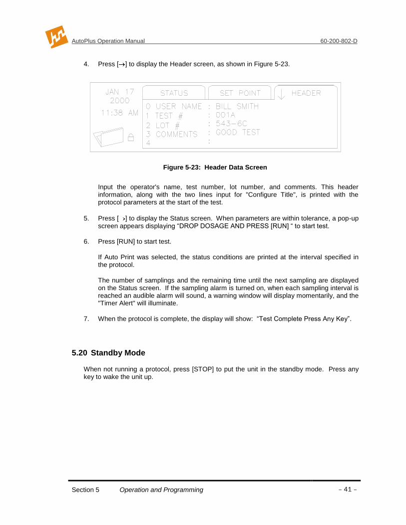
4. Press [ ] to display the Header screen, as shown in Figure 5-23.
Figure 5-23: Header Data Screen
Input the operator's name, test number, lot number, and comments. This header information, along with the two lines input for "Configure Title", is printed with the protocol parameters at the start of the test.
5. Press [ ] to display the Status screen. When parameters are within tolerance, a pop-up screen appears displaying “DROP DOSAGE AND PRESS [RUN] “ to start test.
6. Press [RUN] to start test.
If Auto Print was selected, the status conditions are printed at the interval specified in the protocol.
The number of samplings and the remaining time until the next sampling are displayed on the Status screen. If the sampling alarm is turned on, when each sampling interval is reached an audible alarm will sound, a warning window will display momentarily, and the "Timer Alert" will illuminate.
7. When the protocol is complete, the display will show: “Test Complete Press Any Key”.
5.20 Standby Mode
When not running a protocol, press [STOP] to put the unit in the standby mode. Press any key to wake the unit up.

AutoPlus Operation Manual 60-200-802-D
Section 6 Running A Test
– 42 –
6 Running A Test
6.1 Setting Up
1. AutoPlus
Verify that all liquid and communications connections are connected per the installation requirements, see section 4. Turn power on and select protocol to run, see section 5. Verify media and waste sources are available.
2. MultiFill
Verify that all liquid and communications connections are connected per the installation requirements, see section 4. Turn power on. The display should read “MultiFill Ready”. Install test tubes or vials into rack and place rack on unit.
3. Hanson Bath(s)
Verify that all liquid and communications connections are connected per the installation requirements, see section 4. Verify that the dissolution unit(s) are ready and are within the required specifications. Extra solution may be added to each vessel to accommodate any priming requirement.
4. Other Dissolution Bath(s)
Verify that all liquid connections are connected per the installation requirements, see section 4. Verify that the dissolution unit(s) are ready and within the required specifications. Extra solution may be added to each vessel to accommodate any priming requirement.
5. Sampling Probes and Filters
CAUTION: The AutoPlus valves require 70 micron or better filtration of medium prior to entering valves. Do not operate without filtration.
Verify that all liquid connections are connected per the installation requirements, see section 4. Verify that the probes are adjusted to the correct sampling depth and that the correct number is placed in the correct position. Verify that the specified filter is correctly installed.
6. Printer
Verify that the communications connections are connected per the installation requirements, see section 4. Verify there is adequate paper supply and that the power is on. Both lights should be on and not blinking.
7. Solutions
Verify that there is an adequate amount of media replace and standard and blank material available. Prime all appropriate materials before starting the test, see section 5.

AutoPlus Operation Manual 60-200-802-D
Section 6 Running A Test
– 43 –
6.2 Starting and Running a Test
NOTE: See Section 5 for programming and operational capabilities.
1. Press [START] on the AutoPlus and select a pre-programmed protocol and press [ENTER]. Then select target baths, press the File key to review bath offset and row position, and press [ENTER] to start the test.
The AutoPlus will select and automatically start protocols 1-9 from an SR8-Plus when using protocols 1-9 on the AutoPlus, or run the protocol that has been selected by the operator on the SR8-Plus. To allow the AutoPlus to select the SR8-Plus protocol, do nothing. To select the protocol yourself, just select the protocol you wish to have the AutoPlus start. When the pop-up window on the SR8-Plus comes up saying “DROP DOSE AND PRESS [RUN]”, start the AutoPlus and when it is time, the AutoPlus will start that protocol on the SR8-Plus.
2. Drop dosage into the dissolution vessels in Bath A.
3. Press [START] again on the AutoPlus to set time zero.
4. Drop tablets into the dissolution vessels of subsequent bath(s) when directed by the AutoPlus.
6.3 During the Test
During the test, the AutoPlus will:
1. Count down to the sampling time point and load and dispense the programmed rinse volume to rinse the sampling lines;
2. Draw and dispense the programmed sample volume and send a signal to the spectrophotometer to read the samples and/or collect the programmed sample volume;
3. Replace the volume removed with fresh media, if programmed to do so;
4. Send important information to the validation printer for a hard-copy test report of the process.
6.4 After the Test
After each test ensure a wash cycle is implemented. The wash cycle may be programmed into the protocol to start at the end of the test for unattended system washing.

AutoPlus Operation Manual 60-200-802-D
Section 7 Troubleshooting
– 44 –
7 Section Seven – Troubleshooting
7.1 Contacting Hanson Research Corporation for Technical Support
To expedite your request for Technical Support, please supply the following information:
1. Model and serial numbers of the instrument(s).
1. System configuration. 2. How long the equipment had worked before the problem occurred and how old the
equipment is. 3. Any background information, recent repairs, or parts replaced to date. 4. How the system is being used, what the application is. 5. Detailed information about the problem (what is working and what is not). 6. Detailed troubleshooting steps that have been taken to date.
7.2 Troubleshooting Table
7.2.1 Electrical Troubleshooting
Problem Possible Causes Recommended Action
Power light not displayed on front panel.
Power switch is off. Power is disconnected. Bad fuse. Power supply is defective (no light on power supply).
Turn power switch to the ON position. Check and connect power. Check or replace fuse (see Section 8). Check or replace power supply.
Display will not come on.
AutoPlus is in standby mode. Display back-light is out.
Press any key. Check and replace back-light.
Display not clear. Contrast not set correctly.
Adjust contrast (see Section 5).
Loss of programmed information.
Battery failure. Replace Main Board Smart Block module.

AutoPlus Operation Manual 60-200-802-D
Section 7 Troubleshooting
– 45 –
7.2.2 Mechanical Troubleshooting
Problem Possible Causes Recommended Action
Sample volumes inconsistent.
Not using vial caps. Leaking syringe. Plugged valve.
Use recommended vial caps. Check and replace syringe. Check valve.
Sample volumes incorrect.
Offset volume set incorrectly. Offset volume not set. Plugged valve.
Check and set offset volume. Check and set offset volume. Check valve.
Excessive carryover. Inadequate rinse volume. Used sample filters.
Increase rinse volume. Replace sample filters.
Drug loss. Sample adsorbing to filters or other parts of the liquid flow path.
Evaluate filters; sample may be absorbing to them. See Section 3 for wetted parts.
7.2.3 Printer Troubleshooting
Problem Possible Causes Recommended Action
Light always blinks No paper. Paper incorrectly installed.
Replace paper roll. Check paper to see that it is installed correctly and that the paper indicator button is not stuck. Consult printer operation manual.
Prints a little and then light blinks.
Paper incorrectly installed.
Check paper to see that it is installed correctly and that the paper indicator button is not stuck. Consult printer operation manual.
Will not print. No paper. Paper incorrectly installed. Printer not connected.
Replace paper roll. Check paper to see that it is installed correctly and that the paper indicator button is not stuck. Consult printer operation manual. Connect printer (see Section 4).

AutoPlus Operation Manual 60-200-802-D
Section 7 Troubleshooting
– 46 –
7.2.4 Printer Self Test
Turn power off, hold down both buttons SEL and LF, and turn power back on. When unit begins to print, release buttons. Printer should print: DP614 POWER ON SELECT CR = CR France DRAWER SERIAL INTERFACE 8 BIT NON PARITY 9600 NATIVE

AutoPlus Operation Manual 60-200-802-D
Section 8 Maintenance and Calibration
– 47 –
8 Section Eight – Maintenance and Calibration
8.1 Maintenance Schedule
The AutoPlus should be maintained using the following schedule:
Procedure Frequency
Inspect syringes.
Weekly. (Replace syringe or syringe plungers
at 100,000 cycles or if a leak is detected.)
Replace sample filters. Before each test.
Wash sample lines. After each test.
Clean exterior. As needed.
Clean up spillage. Immediately.
Inspect sample lines and connections. Every 6 months or whenever changed.
Inspect MultiFill operation and needles.
Every 6 months.
Inspect MultiFill belt. Every 6 months.
8.2 General Cleaning
The AutoPlus and MultiFill have been designed to be a low maintenance instrument. In general, the instruments are maintained by wiping clean after each use, as well as running HPLC grade water through the units after each test.
The exterior of the instrument should be periodically wiped down with a damp cloth. Frequency of cleaning depends on instrument usage and operating environment. If there is spillage on the unit, clean it up as soon as possible.
8.3 Cleaning Method for Tubing, Valves and Syringes
Supply HPLC grade water at each sampling input (sampling probes) or at media replace source. Program AutoPlus to pump at least 20mL of solution through (see Section 5). This method should be done after each test.

AutoPlus Operation Manual 60-200-802-D
Section 8 Maintenance and Calibration
– 48 –
8.4 Fuse Replacement
CAUTION: For continued protection against risk of fire, replace fuse(s) with same type and current rating. Disconnect power cord before changing fuse(s).
To check the fuse and replace a defective fuse in the AutoPlus:
1. The fuses are located on the back of the control. The system has one fuse. The amperage is labeled next to the fuse. The fuse holder has a finger grip knob; push in and slightly turn counter-clockwise then pull knob with fuse straight out.
2. Check the fuse with an ohm meter. If you are not sure or if you do not have an ohm meter, replace the fuse.
3. If the fuse is defective, remove the fuse from the holder by pulling it straight out. Replace with a fuse of the same type and rating (see Section 3).
4. Push the fuse back into the control. Secure the fuse holder by pressing in and slightly turning clockwise.
To check the fuse(s) and replace a defective fuse in the MultiFill:
1. The fuses are located on the side of the control where the power cord is connected to the unit. The system has one or two fuses. With a small bladed screwdriver, gently pry the cover/fuse block away from the power entry port housing and remove.
2. Check the fuse with an ohm meter. If you are not sure or if you do not have an ohm meter, replace the fuse.
3. If the fuse is defective, remove the fuse from the holder by pushing it out towards the side. Replace with a fuse of the same type and rating (see Section 3).
4. Slide the cover/fuse block back into the power entry port housing the same way that it came out. Snap the cover/fuse block assembly securely into place.
8.5 Syringe Replacement
Replace syringe plungers when maintenance log indicates 100,000 cycles. After replacing syringe plungers, Volume Calibration should be performed.
1. Remove shoulder screw at bottom of syringe.
2. Grasp barrel with finger and turn to unscrew the syringe end from the manifold.
3. Install the new syringe into the manifold finger tight and replace the shoulder screw.

AutoPlus Operation Manual 60-200-802-D
Section 8 Maintenance and Calibration
– 49 –
8.6 Volume Calibration
Use HPLC grade water at room temperature.
1. Weigh empty sample collection vials with caps and record. Do at least three sets.
2. Program AutoPlus to collect the required sample volume.
3. Weigh full sample collection vials and subtract the empty value from the full. Make any calculations required for water density.
4. To make fine adjustments to the collected volume, use the volume offset function (see Section 5).
8.7 MultiFill Needle Replacement
Visually inspect monthly. Replace as necessary, or every 12 months.
1. Remove collection rack and from the keypad move the dispensing needles out a few rows.
2. Grasp the plastic top of the needle and twist to unscrew. The needle will come away from the connector.
3. Insert new needle and twist until tight. Repeat for each needle.
4. Run a few test cycles to ensure proper operation of the needles and that there are no leaks.
8.8 MultiFill Belt Replacement
CAUTION: Prior to doing any work, turn off the MultiFill and unplug the power source.
1. Remove the collection rack and upper cover to provide access to the drive components.
2. Rotate the drive plate lead screw by hand to position the carriage to the front of the unit.
3. Rotate one needle drive pulley by hand to position the needles in the up position.
4. Remove the 2 flat head screws from under the drive plate assembly. These screws retain the main ACME nut and mounting block (NOTE: A 9-IN long screwdriver works best).
5. Slide the drive plate assembly away from the ACME nut mounting block.
6. Loosen the idler pulley screw using a 5/16 wrench and move the pulley to the fully retracted position.
7. Loosen the 4 screws which secure the drive motor and slide the motor forward to loosen the belt.

AutoPlus Operation Manual 60-200-802-D
Section 8 Maintenance and Calibration
– 50 –
8. Remove the old belt and install new belt (P/N 91-220-017).
9. Reinstall the ACME screw mounting block and secure with 2 flat head screws.
10. Slide the drive motor back to remove belt freeplay and tighten 4 motor screws.
11. Adjust idler pulley position to provide final belt tensioning. A properly adjusted belt may be easily deflected about 1/8-in at midpoint between two pulleys.
12. Rotate the main drive screw manually to verify proper operation.
13. Manually rotate one of the needle drive pulleys and verify proper up/down needle operation.
14. Replace upper cover, install collection rack and reconnect power source.
15. Operate the instrument as necessary to ensure proper operation.

AutoPlus Operation Manual 60-200-802-D
Section 9 Moving and Storage
– 51 –
9 Section Nine – Moving and Storage
9.1 Storage
If the AutoPlus will not be used for a short period of time (3 days or more), the instrument should be cleaned and the power should be turned off. If the AutoPlus will not be used for an extended period of time (30 days or more), the instrument should be cleaned, covered, and unplugged from the power source.
9.2 Moving
The instrument is heavy and great care should be taken when moving it. If the instrument is moved to a new location, revalidation should be considered.
9.2.1 AutoPlus
1. Remove all liquid sources and program the AutoPlus to pump 20mL of air to clear as much liquid from the system as possible.
2. Turn the power off. Disconnect all tubing, communication, and electrical connections from the unit.
9.2.2 MultiFill
1. Turn the power off. Remove rack and secure needle arm.
2. Disconnect all tubing, communication, and electrical connections from the unit.

AutoPlus Operation Manual 60-200-802-D
Section 10 Service Parts
– 52 –
10 Service Parts
Below is a list of service parts needed for proper maintenance of the Hanson AutoPlus.
Cable, RS232 Communication, 9‟ Long .................................................. 47-200-759 Plug, Communication, MultiFill ................................................................. 60-200-300 Power Supply, External, AutoPlus ........................................................... 91-110-019 Power Cord for AutoPlus Power Supply (91-110-019) ........................... 91-211-013 Syringe, 5mL, AutoPlus ............................................................................ 60-200-550 Syringe, 10mL, AutoPlus .......................................................................... 60-200-554 Screw, Shoulder, Syringe, AutoPlus ........................................................ 91-418-055 Valve Assembly (4 valves on top of syringe), Maximizer ........................ 60-200-425 Valve Assembly (singe valve on top of syringe), Dissoscan................... 60-200-475 Board, Main Assembly, AutoPlus ............................................................ 60-200-315 Belt, Drive, MultiFill ................................................................................... 91-220-017 Sensor, Home, MultiFill ............................................................................ 91-220-021 Needle Guide, MultiFill, PEEK™.............................................................. 60-200-514 O-Ring, 1/16” I.D., MultiFill ....................................................................... 91-425-027 Check Valve, MultiFill ............................................................................... 91-601-270 Probe, Stainless 1/8” x 13” Long for 1 tubing channel, AutoPlus ........... 60-200-703 Needle with Plastic Luer, MultiFill ............................................................ 60-200-517 Fuse, 3 Amp, AutoPlus............................................................................. 91-212-065 Fuse, 3 Amp, MultiFill, 115V .................................................................... 91-212-071 Fuse, 1.6 Amp, MultiFill, 230V ................................................................. 91-212-072
For a full list of AutoPlus Accessories and Spare Parts, please consult our current catalog.

AutoPlus Operation Manual 60-200-802-D
Section 11 Sales and Support
– 53 –
11 Sales and Support
The AutoPlus is sold and serviced by a worldwide network of dealers and distributors. If you need additional accessories, replacement parts, or require service information, you may either contact your local agent, or you can contact Hanson Research Corporation at our worldwide headquarters:
Hanson Research Corporation
Corporate Headquarters
9810 Variel Avenue Chatsworth, CA 91311 USA P: 818.882.7266 or 800.821.8165 (toll free) F: 818.882.9470
Web Site
www.hansonresearch.com
Sales Support
For quotes, literature, and sales assistance in the USA and worldwide, please email: [email protected].
Customer Support
To place an order, obtain an order‟s status, or request a return authorization, please email: [email protected].
Technical Support
For assistance with applications and other technical support and service questions, please email: [email protected].
When contacting Hanson Research, please help us eliminate duplication of effort amongst personnel and departments by directing your inquiry to one department or representative.

AutoPlus Operation Manual 60-200-802-D
Section 12 General Warranty
– 54 –
12 General Warranty
Hanson Research Corporation (HRC) products are warranted for one full year including parts and labor. Service contracts and Preventative Maintenance contracts are available for post-warranty support. International dealer warranties may vary. HRC makes no warranty, expressed or implied, for glassware, consumables or products not manufactured by HRC, as evidenced by nameplate on the item or other designation. HRC will give responsible assistance to buyer in obtaining from the respective manufacturer whatever adjustment is reasonable in light of manufacturer‟s own warranty. HRC shall be released from any and all obligations under any warranty, either expressed or implied, if the product covered is repaired or modified by other than its own personnel, or made without written authorization of HRC. There are no other warranties, expressed or implied, and HRC shall not be liable under any circumstances for consequential damages.