Embed Size (px)
Citation preview

DISPLACEMENT SENSORS AND THEIR APPLICATION TO CONTROL OF SYNTHETICALLY POWERED PROSTHESES
AND ORTHOSESa
C. Howard Hoshall, B.S. (E.E.) Engineer Staff, Missile Control Systems
Applied Physics Laboratory The Johns Hopkins University, 8621 Georgia Avenue,
Silver Spring, Maryland 20910
Artificial arms and hands operated by batteries, compressed gas, and other power sources are being used by some amputees in preference to conventional prostheses. Powered orthotic devices are also being developed and are in limited use.
It is immediately obvious that any synthetically powered device must be controlled by some means. It is desirable that complete control be exercised by the user in a manner requiring minimal effort. A number of techniques have been utilized for control of synthetically powered prosthetic and orthotic devices. Rudimentary digits and myoelectric signals from intact muscles have been used for this purpose. Also, volitional skin movements have been used successfully in experimental trials described here to control a battery-powered shoulder-disarticulation prosthesis. Transducers of other types which sense motion of one part of the body relative to other parts of the body have been employed by other investigators to control powered devices.
The first seven experimental Applied Physics I ryJJohns Hopkins Medical Institutes (APL/JHMI) prosthec ms were controlled by myoelectric voltages. Amputations 01 LLICJC ~at ients ranged from wrist to above-elbow disarticulations. Muscle sensors could be fitted over the remaining parts of the bice~ above-elbow amputees and over the finger and wrist ~ALCILJUI
voltage 3s of the .--*-...---
a Reprinted from Applied Physics Laboratory Internal Report MCS-0-303, February 1973, operating under Contract N00017-72-G4401 with the Department of the Navy, funded by and developed for the Veterans Administration.

Hoshall: Displacement Sensors and Their Application
muscles of the below-elbow amputees. Noise levels were low enough and muscle voltage levels were sufficiently high so that suitable control signals could be derived from electrical signals sensed at these sites. Control using these inputs was very natural and a minimum of retraining was necessary. A good example of an arrangement in which almost no adaptation is necessary is one in which biceps muscle voltages are used to control elbow flexion.
A displacement transducer was used on the eighth patient, who was a shoulder-disarticulation amputee, and on two other patients. This mode of control was selected because suitable electrical signals were not available on the users' bodies. These systems have worked well in testing done to date and it appears that these transducers may be of value to other developers of powered prosthetic and orthotic systems.
In this monograph, advantages of "proportional" control are discussed. Devices and techniques which have been utilized in APW JHMI programs are described in detail with the expectation that other investigators might benefit from this experience. Some sugges- tions relating to additional applications of these techniques are also made.
A. BACKGROUND
"Conventional" prostheses and orthoses are operated by "body power." Intact parts of amputees' bodies are harnessed, and control cables attached to the harness operate the mechanisms with which the patients are fitted. Cable "strokes" of 3 or 4 in. and cable forces ranging up to 20 lb. and occasionally more are required to operate terminal devices and elbow articulations.
Many patients are not able to produce, with their own muscles, the forces and excursions required to operate conventional body- powered devices. There are a number of reasons for this. One reason is that, in traumatic amputation, injury may have been so severe as to preclude the wearing of the harness required to hold the prosthesis in place on the body and to operate the control cable(s); severe burns may cause such extensive scarring that the amputee cannot wear harnesses. Another reason is that remaining skeletal and muscle systems may have been damaged so badly that strength and/or range of motion are severely impaired and cannot be restored by therapy.
There is, in addition, a large population of patients who are very severely handicapped by central nervous system damage. In many of these cases, the debility is so severe that there seems to be no

1
of prosthetics ~esearch-Fall 1973
possib~~ity that the patient will ever be able to power conventional braces or artificial limbs.
T~ fill the need of those who are so severely handicapped, synthetically powered systems which relieve the patient of the need to supply the power to operate prosthetic and orthotic devices have been developed. Batteries, compressed gas cylinders, and other sources of power are used; the patient need supply only the control , "signal."
Myoelectric signals from intact muscles proximal to amputations ~ have been utilized in a variety of ways. In some of the systems which utilize these muscle voltages, "on-off' control is employed. In a typical application of this kind, power is applied to operate the device when the amplitude of the electrical signal generated by the muscles exceeds a set threshold. The motor runs at full speed in the direction commanded. No gradation of control of the device is possible other than through control of the duration of application of power. Such systems frequently utilize two channels, each of which has a set of electrodes, signal amplifiers and signal conditioners, and power control circuits. One channel usually controls joint rotation in one direction corresponding, say, to flexure of the elbow. The other channel controls joint rotation in the opposite direction. Placement of one set of electrodes on intact biceps muscles would facilitate control of elbow flexure and another set of electrodes on the triceps muscles would control extension of the elbow.
Many variations of on-off control systems which utilize the myoelectric signal as the primary control input have been developed l
and have been used. Some employ sequential control arrangements to provide greater flexibility of operation. One advantage of such systems is that the electronic control circuits are the simplest possible. A desirable characteristic, which is difficult to achieve with on-off control, is smooth operation of the prosthesis. Smooth control is very important in providing movement which is "natural" in effect. Also, the capability of smooth control makes the device much easier to use. For instance, in controlling elbow operation of a prosthesis, proportional control makes it possible for the wearer to bring the forearm up to position from his side with a minimum of "overshoot" and "hunting" which are very evident in most on-off systems. Experience has shown that similar advantages are realized in proportional control of terminal devices.
Johns Hopkins investigators have chosen to utilize proportional control exclusively in the powered prosthetic and orthotic systems they have developed for the Veterans Administration. Systems with proportional control capabilities have been fitted to 11 amputees and to one patient with near-complete paralysis of the shoulders and

Hoshall: Displacement Sensors and Their Application
arms. A representative above-elbow system configuration is shown in Figure 1. The power and control units are in the foreground. Parts which would normally be fitted and fabricated by the prosthetist are in the background. The top of the power unit assembly has the same dimensions as a conventional internal-locking elbow. The power system is furnished assembled to the prosthetist who laminates the plastic parts of the prosthesis to it just as he would to a conventional elbow unit. The complete power assembly includes a locking hinge, which is locked and unlocked by the mechanical cable shown emerging from the hinge at the back of the unit, the drive motor, sensor, electronics unit, and battery pack. The powered cable can be seen emerging from the slot in the front of the motor unit cover. It passes through the forearm pulley assembly, which provides the correct leverage for elbow operation, and then extends to the terminal device. When power is applied to the motor, the cable is retracted by being wound about a pulley inside the motor drive unit. If the cable is retracted by the motor when the elbow is locked, the terminal device will be opened against the resistance of the elastic
FIGURE 1.-Power and control unit assembly for above-elbow-prosthesis.

Bulletin of Prosthetics Research-Fall 1973
bands. If the elbow is unlocked, the elbow joint will rotate and the forearm will raise while the hook remains closed if more force is required to open the hook than to lift the forearm.
In Figure 1, a myoelectric voltage sensor on a cable is shown above the motor on the right side of the photograph. The two electrodes which contact the skin are visible. The interchangeable, rechargeable battery pack is located in the forearm bracket, and is the dark rectangular object behind the forearm pulley. The electronic control circuits are under the external cover of the motor and are not visible in this photograph.
Gross body motions are used to perform various switching functions in these systems. In all of them, however, input from a single control site is utilized for the proportional control capability. The myoelectric sensor shown in Figure 1 is typical. The sensors are placed over muscles proximal to the amputation and voltages generated when the muscles are contracted are sensed through the small stainless steel electrodes which rest on the skin. Operation of a typical system is illustrated in Figure 2 in which control signal amplitude is shown increasing, then decreasing with time. This corresponds to an opening/closing cycle of the terminal device. As the patient increases muscle tension, a corresponding increase of the control signal, which is derived from the muscle voltage, results. The system is designed so that the drive motor does not operate at all
I
CONTROL SIGNAL
AMPLITUDE OR
DNlCE POSITION
FIGURE 2.-Proportional control system operation.

Hoshall: Displacement Sensors and Their Application
until the control signal crosses a "threshold." This provides the equivalent of a "dead space" which minimizes the effects of spurious noise. As the control signal increases in amplitude above the threshold level, the motor responds in proportion to the magnitude of the input voltage. The control cable is retracted by the motor unit. With decrease of the control signal amplitude, the retracted cable is withdrawn from the motor unit by the elastic band or spring in the terminal device or, in the case of the forearm, by gravity.
"Proportional control" implies a number of things. It is imple- mented differently by different investigators. As the term "propor- tional" is used here, it means that the amount 'the cable which operates the prosthesis is retracted by the motor is related to the magnitude of the control voltage applied to .the motor drive unit. When this system is used to operate a voluntary opening hook, the tines are closed when minimum control signal amplitude is applied. As the amplitude of the control signal is increased, the hook opens. When full amplitude signal is applied, the hook is opened fully. If the motor is used to control elbow operation, minimum input signal amplitude corresponds to the "extended" condition and the full signal amplitude corresponds to the "flexed" condition.
As is to be expected, the system has dynamic as well as static characteristics, i.e., if the amplitude of the control signal is increased rapidly, the motor cannot respond instantaneously; there is some delay and the position of the device will lag behind the control signal. This lag is minimized by proper system design and by the use of a motor of adequate size.
In a system controlled by myoelectric voltages, the amplitude of the electrical signal sensed by the electrodes is, under favorable conditions, roughly proportional to tension in the tendons attached to the muscle bundle in which the voltage is produced. The position of the control cable is not precisely related to the control voltage amplitude; no attempt has been made in the APWJHMI systems to achieve close correspondence between cable position and control signal amplitude. Thus, lack of correspondence between muscle tension and control cable position is compounded. Even gross proportionality is very useful, however. Experience has shown that a system like this offers the user decided advantages even though it is not "proportional" in a strict sense.
Disadvantages such as increased complexity with attendant in- crease of cost, size, failure rate, and power consumption have tended to delay the development of proportional control systems. T h e availability of greatly improved integrated circuits at low cost has made practical proportional control systems possible.

Bulletin of Prosthetics Research-Fall 1973
B. APPLICATIONS OF DISPLACEMENT TRANSDUCERS
Some patients do not have suitable myoelectric signals. In these cases, control signals must be obtained from other sources. One technique which seems promising utilizes displacement transducers which produce voltages proportional to mechanical displacement. The outputs from such transducers can be used for control the same way myoelectric signals are used.
A "displacement transducer," as described here, is a device which responds to mechanical displacement of some part of the body relative to a point of reference. Mechanical displacement can be effected by patients in a number of ways. Some readily utilized examples are provided by conventional prostheses which require for their operation displacements obtained by gross movements of the shoulders and intact portions of the arms. For instance, consider the terminal device of a conventional below-elbow prosthesis which is operated by a mechanical control cable attached to a harness. Tension is applied to the cable when the wearer "hunches" his shoulders and/or thrusts his upper arm forward.
When power from external sources is used and the patient is relieved of the necessity of producing relatively large forces with his own muscles, many new possibilities are presented. Since only very small forces and displacements are required, many patients who are not able to produce the cable motion and forces required to operate conventional devices can control powered devices. This may be true of a patient who is weak, as well as one whose muscles, joints, or bones have been damaged. The need for only small forces and displacements also makes possible employment of capabilities which could not otherwise be utilized effectively. Motion of the skin or of voluntarily controllable rudimentary digits is a good example of this. I t also seems likely that techniques can be developed SO that mechanical displacements produced by intact muscle bundles in stumps can be used effectively to operate displacement transducers.
As of February 1973, skin displacement sensors have been utilized on three volunteer test subjects in the Hopkins program. Statistics on these subjects are given in Table 1. Figure 3 )tograph of one of the amputees who uses skin motion to cor prosthesis. This system is typical of two of the shoulder-disa )n patients who have been fitted. T h e motion transducer mode -01 was selected after a thorough exploration was made of t ed side of the amputee's body. No myoelectric signals suitabl ntrol of the prosthesis were found. The amputee can, however, voluntarily control motion of the skin in the vicinity of the injury. AS a result of attachment of the skin to the pectoralis muscle by scar tissue, more
is -a p h c itrol his lrticulatic
of contl ;he injur e for COI

TABLE 1 .--Clinical Experience with Synthetically Powered Prostheses with Displacement Transducer Control
Case
8
10
12
Age
--- 19
--- 44
--- 19
Sex
M
M
F
Notes
Unilateral amputation secondary to agricultural mach'nery accident. Patient had rejected conventional prosthesis for func- tional use; wore it for appearance only. Powered system with elbow and terminal device capabilities fitted approximately 1 year after amputation. Likes prosthesis-wears it approximately 112 time-wears none remainder of time. Prosthesis subjected to very heavy use in carrying heavy object . Acquired amputation. Patient wore no conventional prosthesis. Powered system with elbow and terminal device capabilities fitted more than 10 years after amputation. Skin attached to pectora'is muscle at amputation site. Displacement transducer attached with "double-sticky" tape. Patient too busy for effec- tive followup; prosthesis fitted in "busy" season. Retrieved pros- thesis after 8 months.
Patient had been fitted with conventional prosthesis operated by band around left thigh. Prosthesis was totally unacceptable. Powered system provides operation of both elbows, both terminal devices, and left wrist. One proportional control input from dis- placement transducer operated by movement of acromial process on left shoulder. Wears prosthesis most of the time--does not wish to be without it.
Months' use elect.
pwr.
18
8
4
Occupation
Farmer, vending machine company employee
Landscape con- tractor and horseman
College student
Amputation level
Shoulder dis- articulation (unilateral)
Shoulder dis- articulation (unilateral)
Shoulder dis- articulation (bilateral, congenital)
Bulletin of Prosthetics Research-Fall 1973
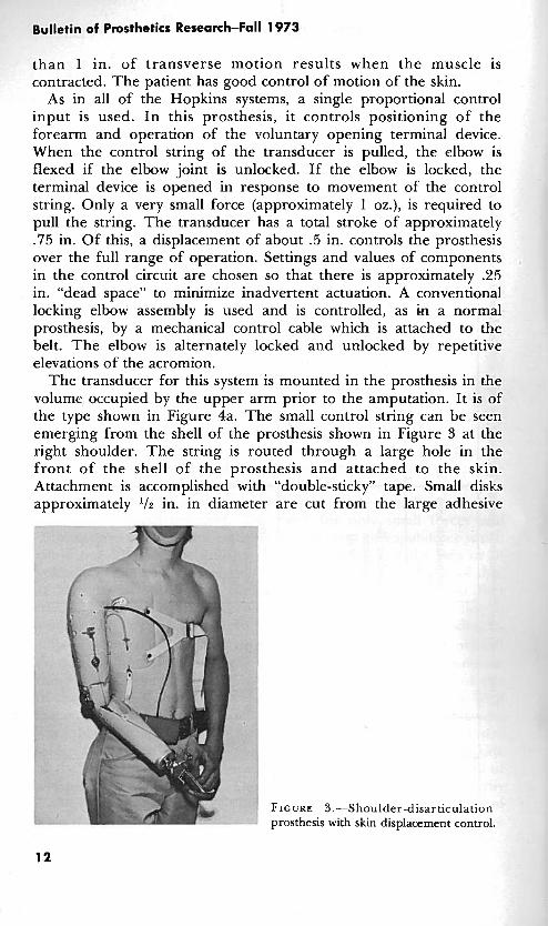
than 1 in. of transverse motion results when the muscle is contracted. The patient has good control of motion of the skin.
As in all of the Hopkins systems, a single proportional control input is used. I n this prosthesis, it controls positioning of the forearm and operation of the voluntary opening terminal device. When the control string of the transducer is pulled, the elbow is flexed if the elbow joint is unlocked. If the elbow is locked, the terminal device is opened in response to movement of the control string. Only a very small force (approximately 1 oz.), is required to pull the string. The transducer has a total stroke of approximately .75 in. Of this, a displacement of about .5 in. controls the prosthesis over the full range of operation. Settings and values of components in the control circuit are chosen so that there is approximately .25 in. "dead space" to minimize inadvertent actuation. A conventional locking elbow assembly is used and is controlled, as in a normal prosthesis, by a mechanical control cable which is attached to the belt. The elbow is alternately locked and unlocked by repetitive elevations of the acromion.
The transducer for this system is mounted in the prosthesis in the volume occupied by the upper arm prior to the amputation. It is of the type shown in Figure 4a. The small control string can be seen emerging from the shell of the prosthesis shown in Figure 3 at the right shoulder. The string is routed through a large hole in the front of the shell of the prosthesis and attached to the skin. Attachment is accomplished with "double-sticky" tape. Small disks approximately ' 1 2 in. in diameter are cut from the large adhesive
FIGURE 3.-Shoulder-disarticulation prosthesis with skin displacement control.

Hoshall: Displacement Sensors and-Their'Application
FIGURE 4.-Magnetodiode transducers (experimental models): a. linear magnetodiode transducer, b. rotary magnetodiode transducer.
"washers" used to attach colostomy and ileostomy containers over surgically prepared openings. Using this double-sided tape, a small clasp like those used on stationery supply envelopes is attached to the skin. A typical "stick-on" button is shown in Figure 4a. With the button stuck to the skin and the prosthesis strapped to the body, the amputee wraps the string one turn around the clasp. The amputee can don the prosthesis without aid very quickly and easily. This technique also provides a convenient means of adjusting the length of the control string.
This arrangement has worked very well. Once attached, the button

Bulletin of Prosthetics Research-Fall 1 973
FIGURE 5.-Bilateral prosthesis for congenital shoulder-disarticulation amputee (covers removed).
is left in place until it becomes loose. The skin is cleansed well with rubbing alcohol before the adhesive disk is attached. If a good attachment is achieved, the button normally stays in place 2 or 3 weeks. The patient can bathe with it in place, and perspiration does not unduly loosen the adhesive. The prosthesis has been worn for approximately 1-'12 years by this amputee without difficulty with the button.
Figure 5 is a photograph of a prosthesis which has been fitted to a bilateral congenital shoulder-disarticulation amputee who is in her late teens. She is now a college student. The device is quite complex, and details will not be given here. One motor provides all of the mechanical power to operate'a system of cables, clutches, brakes, and pulleys to provide elbow flexion of both arms, terminal device operation for both sides, and wrist rotation for the left side. It also has an "eat mode" in which elbow flexure and wrist rotation are automatically coordinated to permit the user to impale food on a fork and lift it to her mouth. One displacement transducer provides the input for proportional control of all functions. The prosthesis also has chin nudge controls and paddle switches with which on-off control functions are accomplished.

Hoshall: Displacement Sensors and Their Application
This prosthesis was fitted with limited expectation of success. It was made, nevertheless, so that experience in the management of difficult cases could be gained. It has performed very well, and the amputee is extremely pleased with it. She wears it most of the time.
This amputee has no myoelectric signals which are suitable for control of the prosthesis. She does, however, have the capability of moving and controlling acromial processes on both shoulders. These processes were not in evidence in her early years. Unlike the acquired shoulder disarticulation described previously, there is no attachment of the skin to underlying bony structures. As the acromial processes are moved the skin also moves, but the amputee does not have precise control of skin position.
For the first fittings, a stick-on button was utilized and the control string was attached to it. This was not satisfactory. An arrangement which has performed much better in this application has evolved. It can be seen in Figure 5. The displacement transducer is mounted on the back of the shell on the left side. It requires 2 oz. of force and has a .75 in. "stroke." T h e control string passes over the left shoulder. An elastic band holds it in position. The amputee controls the transducer by moving the acromial process under the elastic band. After initial adjustments are made, the amputee does not need to readjust the string. This patient is very resourceful and is very proficient in the use of her feet. She dons the prosthesis without aid. This includes securing the Velcro chest straps with her feet.
C. EXPERIMENTAL TRANSDUCER DESIGN
Several experimental displacement transducers have been fabri- cated. The design shown in Figure 4a and described in detail in this report has been used in prostheses made for clinical evaluation. General specifications are listed in Figure 6. One of these units which has been in use on a shoulder-disarticulation prosthesis for approximately 18 months has not required adjustment or repair.
A cross-section view of this transducer design is shown in Figure 7, and details of parts and assembly are shown in Figures 8 and 9. No great effort was made to miniaturize the device-the main objective was to design a transducer which was as simple and as near trouble- free as possible. As shown in Figure 7, the magnets are oriented so as to repel each other. This was done to eliminate the need for a spring. When the control string is pulled and the movable magnet changes position inside the tube, the magnetic field strength in the vicinity of the magnetic sensor changes.
The sensor is a Sony Magnetodiode@ Type MD230A. This is a

Bulletin of Prosthetics Research-Fall 1973
These qualitative specifications are listed to facilitate summarization of experience gained in clinical evaluations.
SIZE AND FORM FACTOR:
1/2" H x 1/2" W x 4" L is satisfactory for shoulder disarticulation applications where size is not critical. In other applications, low profile is usually desirable; a device 3/8" H x 3/4" W x 3/4" L is satisfactory. Smaller transducers should be easy to develop.
WEIGHT:
2 ounces or less
STRING TENSION:
1-3 ounces. The lower limit represents the smallest force that will reliably retract the control string under conditions of maximum re- straint; e.g., by clothing. Experience has shown that up to 1-1/2 oz. can be readily developed by attachment to the skin; more force can be provided in other ways.
STROKE :
Active: 1/2". Transducers with this stroke provide a good compromise between excessive tendency to jitter and insufficient sensi- tivity. Present systems have gain controls by which sensi- tivity can be adjusted.
Dead Space: 1/4" . This is provided electronically in present systems.
OUTPUT :
Voltage: 2 volts. This is achieved with present magnetodiode trans- ducers without amplification. This requirement depends entirely upon circuit design.
Impedance: 1K or less.
FIGURE 6.-Tentative specifications, displacement transducers for control of prosthetic and orthotic devices.
, MAGNET \
t/
BAR MAGNETS ORIENTED SO AS TO REPEL
FIGURE 7.-Magnetodiode transducerscross section (experimental model).

Hoshall: Displacement Sensors and Their Application
MAGNET BORE AND MODE SUIT
PWMER STAINLESS STEEL
SECTION A-A
NYLON MATERIAL
MAGNETS STK. # 40410 EDWND SCIENTIFIC W. eqanr AND WINO m MMENSIONS.
PLUG TO BE HARD W9H FIT DRILL INTO HOUSING 06261) THRU.
\ p~NSEP%EUINo
ARMATURE E T
PLUG NYLON
FIGURE 8.--Magnetodiode transducer-parts detail (experimental unit).
r n H LEADS WRES
SIGNAL OUTPUT
1 AND TERMINAL
COVER HOUSING WITH SHRINKABLE TUBING OR EWIVA~ENT Y
BACK VIEW
, ;I -
NOTE: UNIT MUST BE MOUNTED WITHIN f 45O OF VERTICAL FOR NORMAL OPERATION.
NYLON FISHNO UNE (IS)* E S T )
MAGNETOD
BRACKET
5052 ALUMINUM
II FRONT VIEW
FIGURE 9.-Magnetodiode transducer-assembly and installation details (experimental model).
Bulletin of Prosthetics Research-Fall 1973
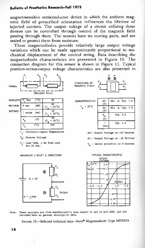
magnetosensitive semiconductor device in which the ambient mag- netic field of prescribed orientation influences the lifetime of injected carriers. The output voltage of a circuit utilizing these devices can be controlled through control of the magnetic field passing through them. The sensors have no moving parts, and are sealed to protect them from moisture.
These magnetodiodes provide relatively large output voltage variations which can be made approximately proportional to me- chanical displacement of the control string. Data describing the magnetodiode characteristics are presented in Figure 10. T h e connection diagram for this sensor is shown in Figure 11. Typical position-versus-output voltage characteristics are also presented in
H H &--$-&-$, DIRECTIONS OF 0 @
SYMBOL I I MAGNETIC FIELD I L-- ---, ,--J
(Matched Pair)
CHARACTERISTICS
Ta = 2S°C
I surge (ma) (Ta = 2SoC)
(Ta = 25'C)
TL (OC) 200 1 I I
T.: Intrinsic-region Temperature Av+: Output Voltage at +lK Oersted
AV+ Min . 8 , Typ. 1.0
AV- Min .8, Typ. 1.0
(V) I Typ. 1.0 (ma)
V . Reverse Voltage R ' Av-: Output Voltage at -lK Oersted
T . Lead Temp. 5 mm from case L' for 10 sec.
MEASURING CIRCUIT 4 CONDITIONS
V : Center potential at 0 Oersted
TYPICAL CHARACTERISTIC
Note: These excerpts are from manufacturer's data sheets in use in mid-1969, and are included here as general descriptive data.
FIGURE 10.Selected technical d a t a S o n y a Magnetodiode Type MD230A

Hoshall: Displacement Sensors and Their Application
TO INPUT OF CONTROL CIRCUIT
TO SIGNAL GROUND
L -'y-..ym-;5v ' BATTERY PACK
LEAD ORIENTATION 8 APPROXIMATE DIMENSIONS, SONY MAGNETODIODE
MD 23OA
SCHEMATIC
t0 .7V
OUTPUT VOLTAGE 0 - (TYPICAL)
- 1.4V
t CONTROL ROD POSITION ROD
t ROD
EXTENDED IN
Ic------ APPROX. .75"-
OUTPUT VOLTAGE CHARACTER lSTl C FIGURE 11.Schematic and output voltage characteristics-magnetodiode displacement transducer.
Figure 11. In the Hopkins systems, the voltage output from the motion transducer is applied to the junction in the control circuit where the output from the amplitude detectorlbuffer amplifier is normally applied in a system in which m~oelectric control is utilized.
A rotary version of this displacement transducer is shown in Figure 4b. This working model was fabricated to demonstrate one way in which size and weight of the linear motion unit might be

TABLE 2.-Mechnical-to-Electrical Transducer Elements jm Control of Prosthetic and Orthotic Devices
Transducer element
Potentiometer Rotary
L iea r
Photoelectric device
LVDT (Linear variable d i m - ential transformer)
Hall effect devices
-essure/force sensors
Principles of operation and application
Control string motion converted to rotary motion by gears or pulley
Operated directly by control string
Optical coupling between light source and photodetector modu- lated by control string position variation
Liiear motion required-Oper- ated directly by control string
Output dependent upon magnetic field strength and orientation
Semiconductor elements respond to forces applied to external surface
Notes, advantages/diadvantages
Good candidate for this applica- tion. High quality units relatively large and expensive-less expensive units probably satisfactory
Commercial units relatively large and expensive
Good candidate for this application
Commercial units relatively large and expensive
Good amplifiers required for stability and gain. Magnetodiode system more attractive at present time
Commercial units presently avail- able are relatively expensive
Ancillary equipment
Simple amplifier for low impedance loads
Simple amplifier for low impedance loads
Light source, photo- detector, amplifier
Oscillator, signal detector, amplifier
Magnet, amplifiers
Simple amplifier
Life expectancy
50 x 107 revolutions (typical)
<I06 operations (typical)
No inherent limita- tions in snsor ele- ment life
No inherent limita- tions in sensor ele- ment life
No inherent limita- tions in sensor ele- ment life
No inherent limita- tions in sensor ele- ment live

c Y
E V) A
3 Y 2 U
3 CI .* 1
i?
j'l 3 1s a > 9 .!I : 2.d Y m o U u g g J 0 l . v Z n a s
9 - a E <
c. O 8 8 u .G 2 : z, 2 = a 8
2
a D .- 0 Y lx E
Y .- .a
1 u 8 a
B $ 1
l z U
Hoshall: Displacement Sensors and Their Application
Bulletin of Prosthetics Research-Fall 1 973
reduced. A magnetodiode is used .as the sensitive element in this transducer also. This device operates satisfactorily but, in its present form, it is not rugged enough for long-term amputee evaluation. Additional design refinement is required to make it suitable for production and amputee evaluation.
There are several other transducer elements which have been considered, but which have not yet been used in this program. A tabulation of their salient characteristics and comments relating to the suitability of each for this application-especially as they compare to the present magnetodiode transducer-is made in Table 2.
D. ADDITIONAL APPLICATIONS OF DISPLACEMENT SENSORS
During the initial stages of development of these displacement transducers, a search was made for ways in which they could be used. Many ideas which would "work," at least for limited periods of .time, were considered. However, almost all of these, in one way or another, violated basic requirements as they are now understood. Any such device must require a minimum of initial adjustment and readjustment. It must be reasonably comfortable, easily donned, and relatively insensitive to changes of position of the prosthesis relative to the body. Any attachment or implantation technique must be suitable for prolonged use. It must not cause soreness or be likely to induce infection or other pathological conditions. Whatever motion is sensed should be controllable. Furthermore, the involved muscle cannot simultaneously be committed to another function. For example, if an amputee uses the muscles in his stump to stabilize his prosthesis socket by voluntarily contracting these muscles in order to increase the transverse diameter of his stump, he cannot simultane- ously use these muscles for control signals. One requirement that must always be met is that the system must be easily controlled and must present a minimum of possibilities for confusion.
Suggestions for possible applications of displacement sensors are listed in Table 3. Some of these suggestions have already been implemented in the Hopkins program as described in this report. Others, particularly those which relate to quadriplegia, have been implemented in various forms by others; sophisticated manipulator- type devices have been used for some time. The suggestion for the use of this type of transducer with quadriplegic patients is included in Table 3 with the hope that those experienced in the management of such cases may find additional ways to utilize simple motor drive units and transducers like the ones described here.
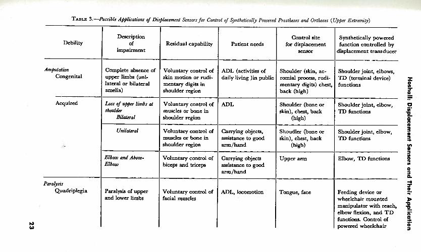
TABLE 3. -~oss ib lc '~~l ica t ions of Disglacmcnt Sensors for Control of Synthetically Powered Prostheses and Orthoscs (Upper Extrcmify)
Patient needs
ADL (activities of daily living )in public
ADL
Carrying objects, assistance to good arm/hand
Carrying objects assistance to good arm/hand
ADL, locomotion
Residual capability
Voluntary control of skin motion or rudi- mentary digits in shoulder region
Voluntary control of muscles or bone in shoulder region
Voluntary control of muscles or bone in shoulder region
Voluntary control of biceps and triceps
Voluntary control of facial muscles
Debility
Amputation Congenital
- Acquired
Paralysis Quadriplegia
Description of
impairment
Complete absence of upper limbs (uni- lateral or bilateral amelia)
Loss of upper limbs at slrouldcr
Bilateral
Unilateral
Elbow and Abovc- Elbow
Paralysis of upper and lower limbs
Control site for displacement
sensor
Shoulder (skin, ac- romial procou, rudi- mentary digits) chest, back (high)
Shoulder (bone or skin), chest, back
(high)
Shoudler (bone or skin), chest, back
(high)
Upper arm
Tongue, face
Synthetically powered function controlled by
displacement transducer
Shoulder joint, elbows, TD (terminal device) functions
Shoulder joint, elbow, TD functions
Shoulder joint, elbow, TD functions
Elbow, TD functions
Feeding device or wheelchair mounted manipulator with reach, elbow flexion, and T D functions. Control of powered wheelchair
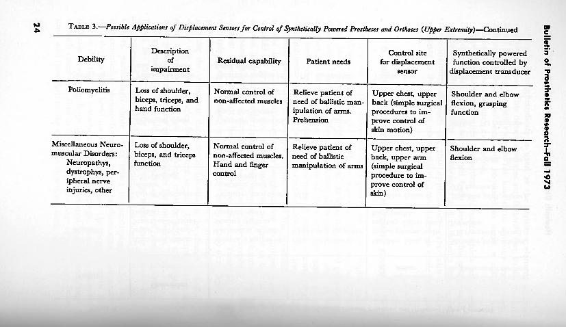
2 TABLE 3.-Possible Applications of Displacement Sensors for Control of Synthetical[y Powered Prostheses and Orthoses ( U w
Debility Description
of impairment
Poliomyelitis I Loss of shoulder, I Normal control of Relieve patient of Upper chest, upper biceps, triceps, and non-affected muscles I need of ballistic man- 1 back (simple surgical
Residual capability
hand function
Patient needs
Miscellaneous Neuro- ( Loss of shoulder, I Normal control of I Relieve patient of 1 Upper chest, upper
Control site for displacement
sensor
ipulation of arms. Prehension
procedures to im- prove control of skim motion)
muscular Disorders: Neuropathys, dystrophys, per- ipheral nerve injuries, other
5!. Synthetically powered 3 '
function controlled by % displacement transducer ir
3 r Shoulder and elbow flexion, grasping ;
n function F s
biceps, and triceps function
non-affected muscles. Hand and finger control
6
Shoulder and elbow 5 I n
flexion 9 - need of ballistic manipulation of arms
back, upper arm (simple surgical procedure to im- prove control of

Hoshall: Displacement Sensors and Their Application
An adaptation of these displacement transducers, which has not yet been evaluated, appears to have potential in a number of applications. This involves use of a flexible control cable. A conceptual representation of such a cable and a proposed application are shown in Figure 12. Instead of the control string being routed directly from the prosthesis to the body or passing through a piece of tubing which acts only as a guide, it passes through a flexible tube. The tubing is anchored to the case of the transducer and acts as the outer sheath of a Bowden cable. The end of a flexible cable like this can be moved about relative to the transducer case without moving the position-sensitive elements inside. Motion of the control string relative to the sheath is required to produce a variation in the voltage output of the transducer. Lightweight flexible tubing can be used because only small compression forces result from application
DISPLACEMENT TRANSDUCER
(REPRESENTATIVE)
STUMP SOCKET
ELASTIC BAND STRING GUIDED UT NOT ATTACHED
DETAIL
F~GURE 12.-Transducer application: a. displacement transducer with flexible control cable, b. application of displacement transducer with flexible control cable in above- elbow prosthesis.

Bulletin of Prosthetics Research-Fall 1973
of the very low tension required to operate the control string. r prototype of a transducer like this has been made but a sensor wit1 a flexible control cable has not yet been used in the Hopkin program; no results of clinical evaluations can be cited.
The arrangement shown in Figure 12b should be useful with shor above-elbow amputations where it is difficult to use myoelectri sensors. The biceps and triceps bulges which result when thes, muscles are contracted are utilized. As the muscles bulge the elasti band is stretched and the control string is withdrawn from th sheath. It should 'be very easy for the amputee to don such prosthesis. He need only put his stump into the socket. N I attachments to the skin need to be made. In other application where muscle bulges cannot be utilized so readily, two small pad attached to the skin with double-sided adhesive tape or by some other means could be used to anchor the outer sheath and control string to separate points on the skin.
Techniques like this could possibly be used to advantage in applications such as the following:
Above-elbow amputees
In many cases where the arm has been amputated at the elbow or above, the biceps muscles become attached to the skin which may move as much as an inch when the muscles are contracted. This motion could be utilized by routing a flexible control cable into .the socket and attaching the sheath and control string to the skin at two places. It may be possible also to devise some sort of simple harness or sock which could be anchored inside the stump socket and into which the amputee could readily insert his stump. The end of the flexible cable would be permanently attached to this inner harness.
Paralysis patients
Because transducers with flexible control cables do not have to be kept in a fixed position relative to the patient's body, they may find use by patients who are confined to wheelchairs and who may have controllable "flickers" of motion of parts of the body or of the skin. Transducers could be mounted on the chair and the flexible cables run to suitable control sites on the patient's body. It would not be necessary for the patient to wear harnesses o r fixtures, and impediment of any motion of which he might be capable would be minimal.
Other ways of effectively utilizing low force capability, small excursion displacements are being sought. As one possibility, "simple surgical procedures" are listed in Table 3. This suggestion is made with full knowledge that almost always there is on the part of both

Hoshall: Displacement Sensors and Their Application
physician and amputee a reluctance to seriously consider even the simplest "unnecessary" surgery. This is especially understandable in the case of amputees who have already undergone extensive surgery-in some cases under traumatic conditions. The possibility of simple surgery should be given consideration nevertheless. It could take a number of forms. In cases where the patient has inadequate ability to control the position of the skin, surgical attachment of the skin to an underlying muscle could be made at selected places so that the patient would then have fine control of skin motion.
The stick-on button described in this report has served a very useful purpose in that it has provided an expedient way of evaluating the potential of prostheses of this type. Results have been very encouraging. Alternative methods are also being considered. One idea which is compatible with the use of a displacement transducer operated by a control string is the surgical creation of skin-lined holes like miniature cineplasty tunnels. Small hooks or rings similar to those for pierced ears could be fashioned from body- compatible materials and inserted in the skin-lined holes. The control strings could then be attached to the rings or hooks. To the writer's knowledge, there are no proven techniques which can be applied in this application. Two of the problems which are known to exist with such alterations of the body surface are the tendency of the skin tunnel to close and the problem of hygiene.
E. CONCLUSION
Clinical tests and evaluations of synthetically powered prosthetic and orthotic "hardware" are yielding encouraging results. At this stage of development of these systems, there appears to be an urgent need for improvement in techniques of communication between the patient and the aids he uses. A few possibilities for ways in which this might be accomplished have been discussed in this report.
The writer wishes to thank G. Schmeisser, Jr., M.D., for his counsel regarding medical aspects of this report.
GENERAL REFERENCES
1. Seamone, W. and C.H. Hoshall: A Single Site Myoelectric Control System for Prostheses. Paper presented at the Third International Symposium on External Control of Human Extremities, Dubrovnik, Yugoslavia, August 1969.
2. Seamone, W.: Development and Evaluation of ~xternally Powered Upper-Limb Prosthesis, Summary o f Research Project Activities, July 1, 1969-December 3 1, 1969. Bull. Prosthetics Res., BPR 1&13:57-63, Spring 1970.

Bulletin of Prosthetics Research-Fall 1973
3. Seamone, W. and G. Schmeisser, Jr.: Development and Evaluation of Externally Powered Upper-Limb Prosthesis, Summary of Research Project Activities, July 1970-July 1971. Bull. Prosthetics Res., BPR 10-16:169-176, Fall 1971.
4. Seamone, W. and G. Schmeisser, ~r::. Development and Evaluation of Externally Powered Upper-Limb Prosthesis, Summary of Research Project Activities, July 1971-December 1971. Bull. Prosthetics Res., BPR 10-17:33-37, Spring 1972.
5. Seamone, W., G. Schmeisser, Jr., and C.H. Hoshall: A Powered Cable Drive for Prosthetic-Orthotic Systems. Paper presented at the Fourth International Sympos- ium on External Control of Human Extremities, Dubrovnik, Yugoslavia, ~ u & s t 1972.
6. Schmeisser, G., Jr., and W. Seamone: An Upper Limb Prosthesis-Orthosis Power and Control System with Multi-Level Potential. Paper presented at American Society for Surgery of the Hand meeting, Las Vegas, Nevada, February 1, 1973.