Embed Size (px)
Citation preview
Discussion of Noise and VibrationAnalysis and Control
www.boydcorp.com
One Company, Many Solutions
White Paper
Boyd Corporation
One Company, Many Solutions
www.boydcorp.com
With decades of experience and a wholly-owned global footprint, Boyd provides best-cost, engineered, specialty material-based energy management and sealing solutions through comprehensive technical materials and design expertise, world-class manufacturing quality and service reliability, and unparalleled supply chain management.
Discussion of Noise and Vibration Analysis and Control- An Introduction
Paul Macioce is a Mechanical Engineer with over 25 years of experience working in the area of noise and vibration control, both as a consulting engineer assisting customers to find solutions to their challenging NVH issues, as well as in support of product development of noise and vibration countermeasures. His particular area of expertise is in the design of material-based damping treatments utilizing visco-elastic materials.
Introduction
Anyone who has worked in the automotive industry is likely to be familiar with the acronym NVH which stands for Noise, Vibration & Harshness—a term referring to the general objective of designing cars that run quieter and smoother resulting in a higher quality, more reliable product. Concern with NVH issues goes well beyond the automotive industry to almost every type of part, device or structure, and has become a general concern of most product designers today.
This article is a general discussion on the topic of noise and vibration control and analysis techniques from the perspective of someone who has worked as a consultant in this field of study for many years. At Boyd, we strive to bring this consultative, problem solving approach to how we support our customers’ issues utilizing a systematic and analytical thought process to understand the governing dynamics of a problem in order to best recommend the most appropriate countermeasures.
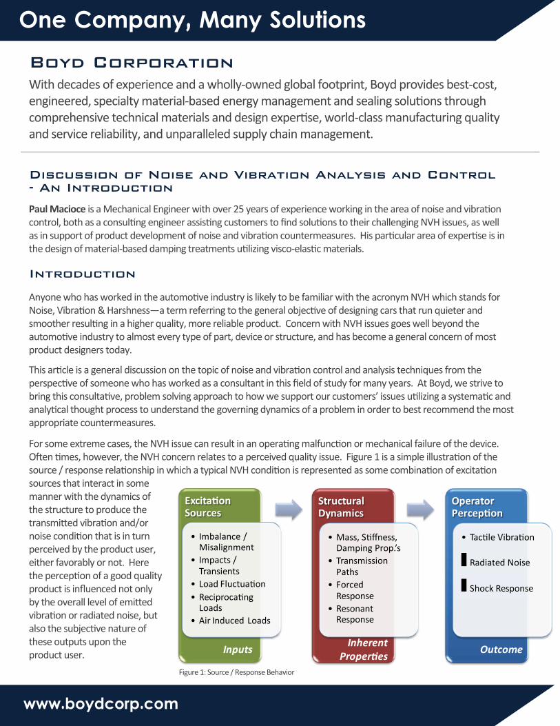
For some extreme cases, the NVH issue can result in an operating malfunction or mechanical failure of the device. Often times, however, the NVH concern relates to a perceived quality issue. Figure 1 is a simple illustration of the source / response relationship in which a typical NVH condition is represented as some combination of excitation sources that interact in some manner with the dynamics of the structure to produce the transmitted vibration and/or noise condition that is in turn perceived by the product user, either favorably or not. Here the perception of a good quality product is influenced not only by the overall level of emitted vibration or radiated noise, but also the subjective nature of these outputs upon the product user.
ExcitationSources
• Imbalance / Misalignment
• Impacts / Transients
• Load Fluctuation• Reciprocating
Loads• Air Induced Loads
Structural Dynamics
• Mass, Stiffness, Damping Prop.’s
• Transmission Paths
• ForcedResponse
• ResonantResponse
OperatorPerception
• Tactile Vibration
• Radiated Noise
• Shock Response
InputsInherent
PropertiesOutcome
Figure 1: Source / Response Behavior
Am
plit
ude
Frequency
1X 2X 3X4X
5X
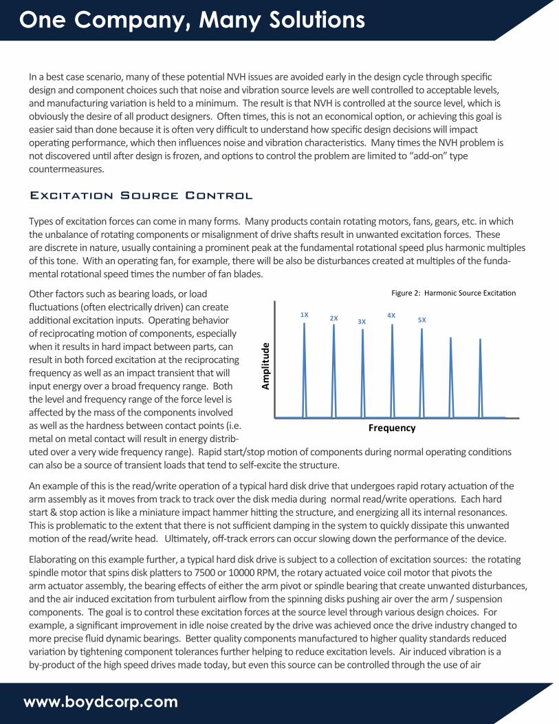
Figure 2: Harmonic Source Excitation
One Company, Many Solutions
www.boydcorp.com
Excitation Source Control
In a best case scenario, many of these potential NVH issues are avoided early in the design cycle through specific design and component choices such that noise and vibration source levels are well controlled to acceptable levels, and manufacturing variation is held to a minimum. The result is that NVH is controlled at the source level, which is obviously the desire of all product designers. Often times, this is not an economical option, or achieving this goal is easier said than done because it is often very difficult to understand how specific design decisions will impact operating performance, which then influences noise and vibration characteristics. Many times the NVH problem is not discovered until after design is frozen, and options to control the problem are limited to “add-on” type countermeasures.
Types of excitation forces can come in many forms. Many products contain rotating motors, fans, gears, etc. in which the unbalance of rotating components or misalignment of drive shafts result in unwanted excitation forces. These are discrete in nature, usually containing a prominent peak at the fundamental rotational speed plus harmonic multiples of this tone. With an operating fan, for example, there will be also be disturbances created at multiples of the funda-mental rotational speed times the number of fan blades.
Other factors such as bearing loads, or load fluctuations (often electrically driven) can create additional excitation inputs. Operating behavior of reciprocating motion of components, especially when it results in hard impact between parts, can result in both forced excitation at the reciprocating frequency as well as an impact transient that will input energy over a broad frequency range. Both the level and frequency range of the force level is affected by the mass of the components involved as well as the hardness between contact points (i.e. metal on metal contact will result in energy distrib-uted over a very wide frequency range). Rapid start/stop motion of components during normal operating conditions can also be a source of transient loads that tend to self-excite the structure.
An example of this is the read/write operation of a typical hard disk drive that undergoes rapid rotary actuation of the arm assembly as it moves from track to track over the disk media during normal read/write operations. Each hard start & stop action is like a miniature impact hammer hitting the structure, and energizing all its internal resonances. This is problematic to the extent that there is not sufficient damping in the system to quickly dissipate this unwanted motion of the read/write head. Ultimately, off-track errors can occur slowing down the performance of the device.
Elaborating on this example further, a typical hard disk drive is subject to a collection of excitation sources: the rotating spindle motor that spins disk platters to 7500 or 10000 RPM, the rotary actuated voice coil motor that pivots the arm actuator assembly, the bearing effects of either the arm pivot or spindle bearing that create unwanted disturbances, and the air induced excitation from turbulent airflow from the spinning disks pushing air over the arm / suspension components. The goal is to control these excitation forces at the source level through various design choices. For example, a significant improvement in idle noise created by the drive was achieved once the drive industry changed to more precise fluid dynamic bearings. Better quality components manufactured to higher quality standards reduced variation by tightening component tolerances further helping to reduce excitation levels. Air induced vibration is a by-product of the high speed drives made today, but even this source can be controlled through the use of air

One Company, Many Solutions
www.boydcorp.com
Structural Response
straightening devices that help to minimize turbulent air flow, thus reducing this source of broadband excitation to the disk platters and actuator.
In general, strategies for minimizing excitation source levels involve such things as use of light weight components to reduce force levels, minimizing unbalance and misalignment between components, and more precise manufacturing methods that remove unwanted variation. The reduction of reciprocating loads can be achieved by reducing the mass of moving components or the use of inertial counter balances. For geared components, selection of high contact ratios (>2.0), proper lubrication, selection of gear materials, tooth profile and surface finish, and shaft alignment are all factors influencing good gear design and operation. Other methods involve the modification of the actual operating profile whereby sacrifices in speed or power are made for the benefit of better NVH characteristics (i.e. “quiet mode” of a cooling fan that runs at a slower speed often actively controlled to control cooling demand, or an automotive air conditioner that takes longer to cool because of less powerful components, or a hard drive that decelerates slowly to a stop minimizing excitation levels at the expense of longer seek times).
As important to understanding the nature of noise and vibration sources, it is also necessary to develop a thorough knowledge of how the dynamics of the structure interact with these input forcing functions, and which factors are most important to the stated NVH condition. In particular, by what transmission path does the noise and/or vibration follow from the source to the receiver? What is the nature of the frequency content of excitation sources and how does this relate to the structural dynamics of the device? Is the nature of the NVH issue predominately influenced by interaction with resonances of the structure, or does input excitation exist “off resonance” in either the stiffness controlled (low frequency) range, or mass-controlled (high frequency) range? See the figure below for a generalized illustration of typical structural dynamic behavior.
Resonances are present in every structure and are classified as structural instabilities that tend to amply input energy. The level of amplification is a function of the inherent level of damping present in the structure. In a typical frequency response spectrum, as illustrated in Figure 1 for a theoretical structure, resonances are illustrated as sharp peaks occurring at specific frequencies. The level of damping is reflected in the “sharpness” of the peaks; the more rounded in nature, the higher the level of damping present. Location of these peaks in frequency is related to mass and stiffness properties of the structure.
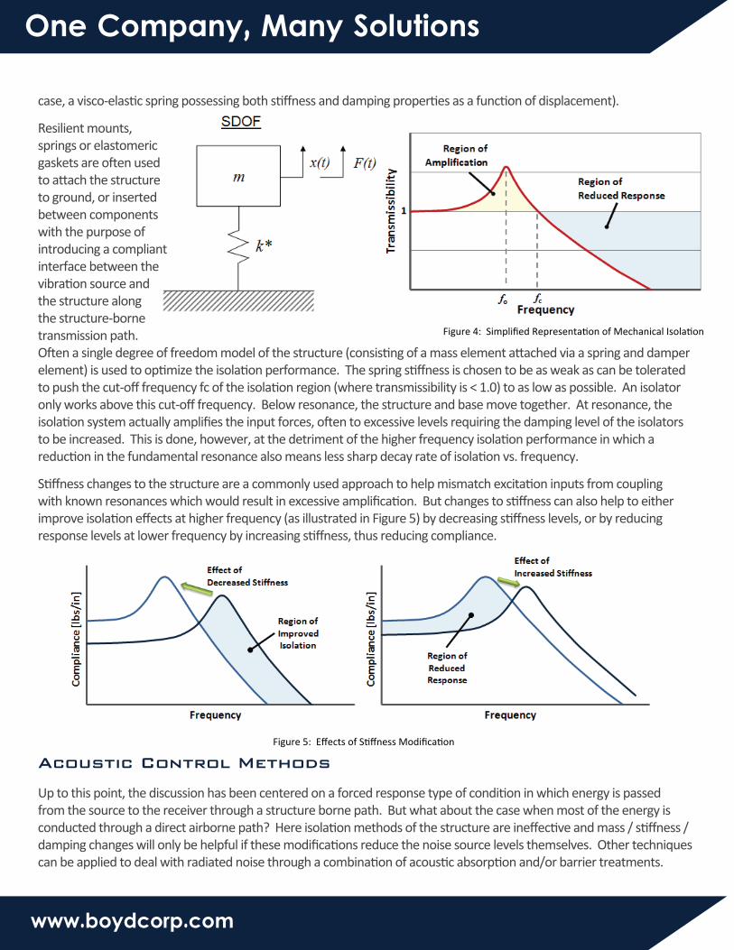
A forced response condition exists when excitation occurs well below these resonances, in the structure’s stiffness controlled region, where response to excitation forces are controlled by the stiffness of the structure. We can also have a forced response condition when excitation inputs are well above resonances in what’s called the mass controlled region of the response. Here inherent compliance between components act to isolate the transmission of vibration, and tend to reduce response levels. The ratio of response motion to input excitation is called transmissibility. See Figure 4 below for a simplified representation of the structure as well as an example of how isolation works to reduce excitation levels at higher frequencies. Here the structure is represented as a lumped mass attached to ground via a spring element (in this
FREQUENCY
MassControlledRegionA
MPL
ITU
DE
DampingControlledRegion
Forced Response
Resonant Response
StiffnessControlled
Region
Figure 3: Typical Structural Response
One Company, Many Solutions
www.boydcorp.com
Acoustic Control Methods
case, a visco-elastic spring possessing both stiffness and damping properties as a function of displacement).
Resilient mounts, springs or elastomeric gaskets are often used to attach the structure to ground, or inserted between components with the purpose of introducing a compliant interface between the vibration source and the structure along the structure-borne transmission path. Often a single degree of freedom model of the structure (consisting of a mass element attached via a spring and damper element) is used to optimize the isolation performance. The spring stiffness is chosen to be as weak as can be tolerated to push the cut-off frequency fc of the isolation region (where transmissibility is < 1.0) to as low as possible. An isolator only works above this cut-off frequency. Below resonance, the structure and base move together. At resonance, the isolation system actually amplifies the input forces, often to excessive levels requiring the damping level of the isolators to be increased. This is done, however, at the detriment of the higher frequency isolation performance in which a reduction in the fundamental resonance also means less sharp decay rate of isolation vs. frequency.
Stiffness changes to the structure are a commonly used approach to help mismatch excitation inputs from coupling with known resonances which would result in excessive amplification. But changes to stiffness can also help to either improve isolation effects at higher frequency (as illustrated in Figure 5) by decreasing stiffness levels, or by reducing response levels at lower frequency by increasing stiffness, thus reducing compliance.
Figure 4: Simplified Representation of Mechanical Isolation
Figure 5: Effects of Stiffness Modification
Up to this point, the discussion has been centered on a forced response type of condition in which energy is passed from the source to the receiver through a structure borne path. But what about the case when most of the energy is conducted through a direct airborne path? Here isolation methods of the structure are ineffective and mass / stiffness / damping changes will only be helpful if these modifications reduce the noise source levels themselves. Other techniques can be applied to deal with radiated noise through a combination of acoustic absorption and/or barrier treatments.
One Company, Many Solutions
www.boydcorp.com
Damping Control Methods
Absorbers are add-on treatments made from porous elastic materials with the ability to absorb a portion of radiated noise and weaken the reflected sound wave. These materials can be fibrous (i.e. fiberglass or polyester) matting materials or flexible cellular foam materials of various type (polyurethane, polyimide, polypropylene, etc.). Absorbers can be cut to various thicknesses (the thicker the better to absorb down to lower frequencies with longer wavelengths) to line the inside walls of an enclosure encapsulating a noise source, or creating a ducted air path through the structure (preferably not in a straight direction, but through a tortuous path).
Absorbers are also combined with limp mass or septum layers to create barrier treatments in which noise is not allowed to pass through the structure, but reflected back into the enclosure. Absorption treatments can also be configured to have a lightweight, perforated skin or embossing pattern to improve lower frequency absorption performance (at the expense of high frequency absorption).
Other more advanced types of airborne based devices such as mufflers, resonators and air straighteners can be incorpor-ated into a structure to help minimize the radiated noise levels of an operating device. Resonators act like narrow band reject filters providing improvement to a specified frequency range as defined by the geometry of the resonating cavity and connecting orifice. Air straighteners help to minimize the turbulent nature of air through an opening or duct by passing the airflow through a honeycomb structure of parallel tubes of specified length and diameter.
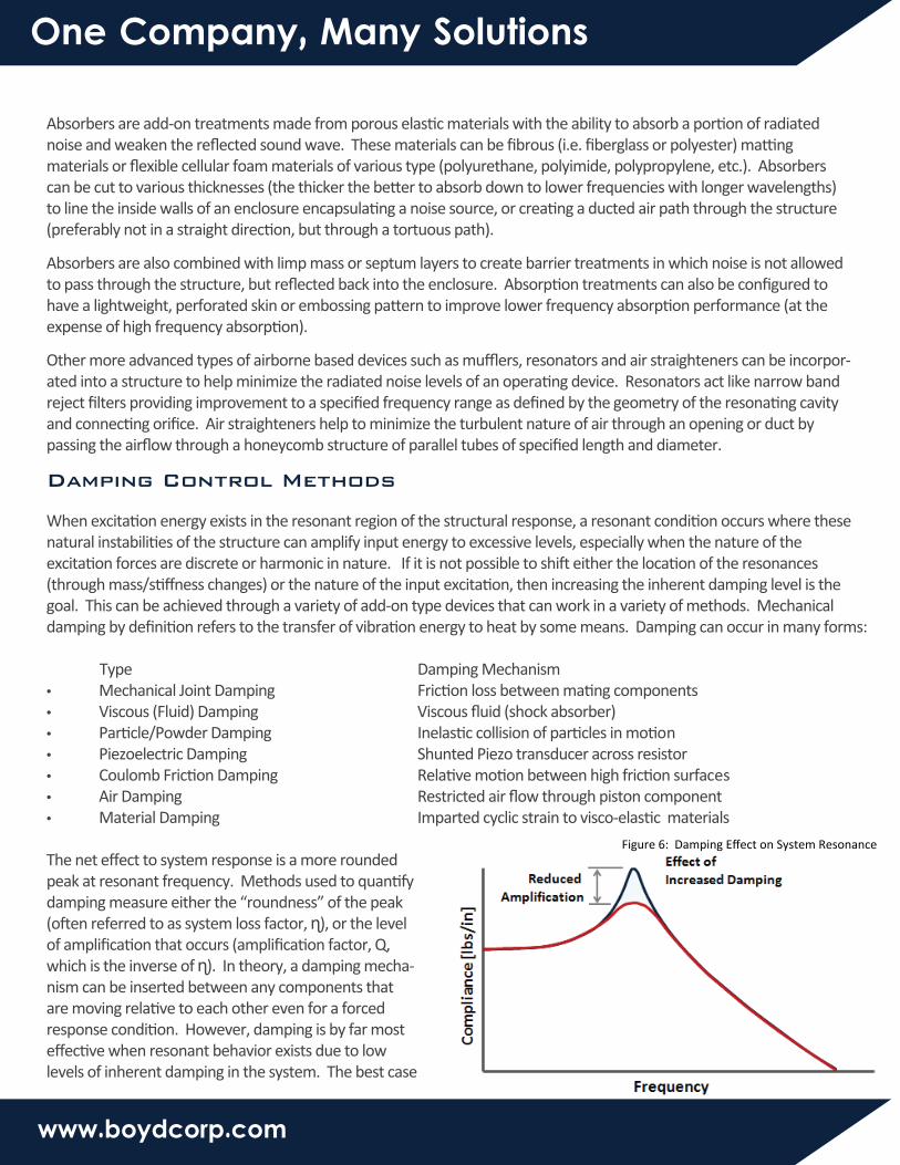
Figure 6: Damping Effect on System Resonance
When excitation energy exists in the resonant region of the structural response, a resonant condition occurs where these natural instabilities of the structure can amplify input energy to excessive levels, especially when the nature of the excitation forces are discrete or harmonic in nature. If it is not possible to shift either the location of the resonances (through mass/stiffness changes) or the nature of the input excitation, then increasing the inherent damping level is the goal. This can be achieved through a variety of add-on type devices that can work in a variety of methods. Mechanical damping by definition refers to the transfer of vibration energy to heat by some means. Damping can occur in many forms: Type Damping Mechanism• Mechanical Joint Damping Friction loss between mating components• Viscous (Fluid) Damping Viscous fluid (shock absorber)• Particle/Powder Damping Inelastic collision of particles in motion• Piezoelectric Damping Shunted Piezo transducer across resistor• Coulomb Friction Damping Relative motion between high friction surfaces• Air Damping Restricted air flow through piston component• Material Damping Imparted cyclic strain to visco-elastic materials
The net effect to system response is a more rounded peak at resonant frequency. Methods used to quantify damping measure either the “roundness” of the peak (often referred to as system loss factor, ɳ), or the level of amplification that occurs (amplification factor, Q, which is the inverse of ɳ). In theory, a damping mecha-nism can be inserted between any components that are moving relative to each other even for a forced response condition. However, damping is by far most effective when resonant behavior exists due to low levels of inherent damping in the system. The best case
Damping Link
m2c
x2(t)
m1
x1(t)
Undeformed
Deformed
Constrained Layer Damper
Undeformed
Deformed
Unconstrained Layer Damper
ViscoelasticElement
One Company, Many Solutions
www.boydcorp.com
Conclusion
scenario for the add-on damping device is to eliminate the amplification of input source levels.
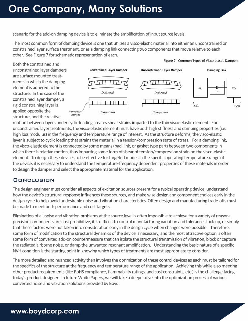
The most common form of damping device is one that utilizes a visco-elastic material into either an unconstrained or constrained layer surface treatment, or as a damping link connecting two components that move relative to each other. See Figure 7 for schematic representation of each.
Both the constrained and unconstrained layer dampers are surface mounted treat-ments in which the damping element is adhered to the structure. In the case of the constrained layer damper, a rigid constraining layer is applied opposite the structure, and the relative motion between layers under cyclic loading creates shear strains imparted to the thin visco-elastic element. For unconstrained layer treatments, the visco-elastic element must have both high stiffness and damping properties (i.e. high loss modulus) in the frequency and temperature range of interest. As the structure deforms, the visco-elastic layer is subject to cyclic loading that strains the material in a tension/compression state of stress. For a damping link, the visco-elastic element is connected by some means (pad, link, or gasket type part) between two components in which there is relative motion, thus imparting some form of shear of tension/compression strain on the visco-elastic element. To design these devices to be effective for targeted modes in the specific operating temperature range of the device, it is necessary to understand the temperature-frequency dependent properties of these materials in order to design the damper and select the appropriate material for the application.
Figure 7: Common Types of Visco-elastic Dampers
The design engineer must consider all aspects of excitation sources present for a typical operating device, understand how the device’s structural response influences these sources, and make wise design and component choices early in the design cycle to help avoid undesirable noise and vibration characteristics. Often design and manufacturing trade-offs must be made to meet both performance and cost targets.
Elimination of all noise and vibration problems at the source level is often impossible to achieve for a variety of reasons: precision components are cost prohibitive, it is difficult to control manufacturing variation and tolerance stack-up, or simply that these factors were not taken into consideration early in the design cycle when changes were possible. Therefore, some form of modification to the structural dynamics of the device is necessary, and the most attractive option is often some form of converted add-on countermeasure that can isolate the structural transmission of vibration, block or capture the radiated airborne noise, or damp the unwanted resonant amplification. Understanding the basic nature of a specific NVH condition is the starting point in knowing which types of treatments are most appropriate to consider.
The more detailed and nuanced activity then involves the optimization of these control devices as each must be tailored for the specifics of the structure at the frequency and temperature range of the application. Achieving this while also meeting other product requirements (like RoHS compliance, flammability ratings, and cost constraints, etc.) is the challenge facing today’s product designer. In future White Papers, we will take a deeper dive into the optimization process of various converted noise and vibration solutions provided by Boyd.