Embed Size (px)
Citation preview
Schempp-Hirth Flugzeugbau GmbH Krebenstraße 25 – Postfach 14 43
D-7312 Kirchheim unter Teck
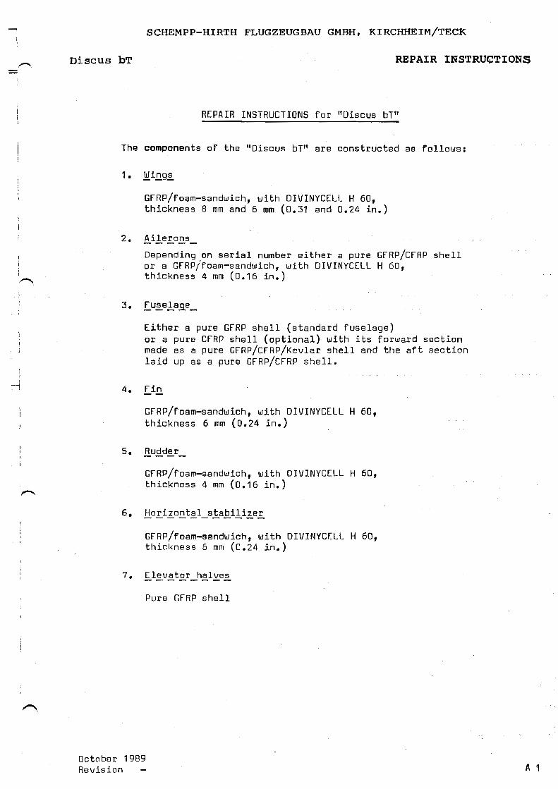
Maintenance Manual for the powered sailplane model
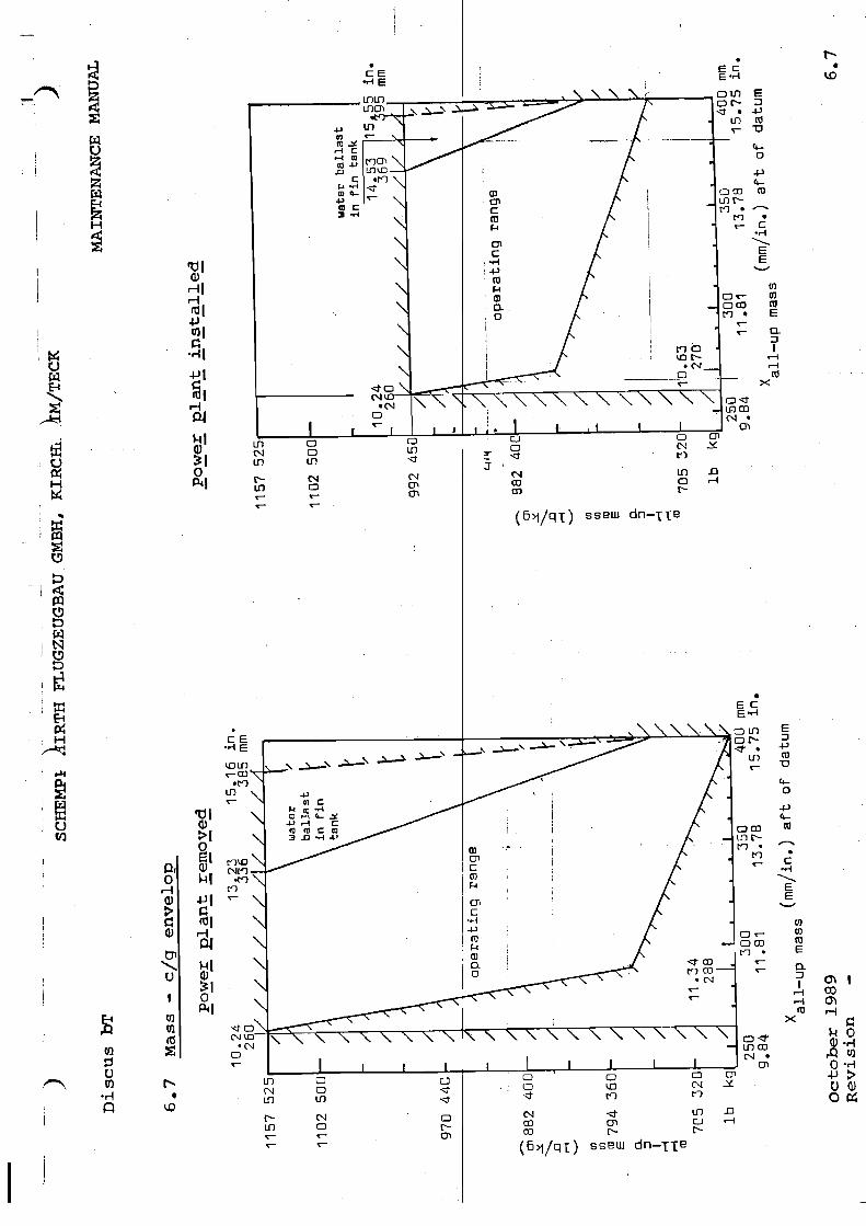
Discus bT Edition: October 1989
Revision: 8, January 2011
This manual relates to the powered sailplane “Discus bT”
Registr.-No. :
Serial-No. :
Manufacturer : Schempp-Hirth Flugzeugbau GmbH
Owner :
The translation of this manual has been done by best knowledge and judgment, In any case of doubt the original text in German language is authoritative.
SCHEMPP-HIRTH FLUGZEUGBAU GMBH, KIRCHHEIM/TECK
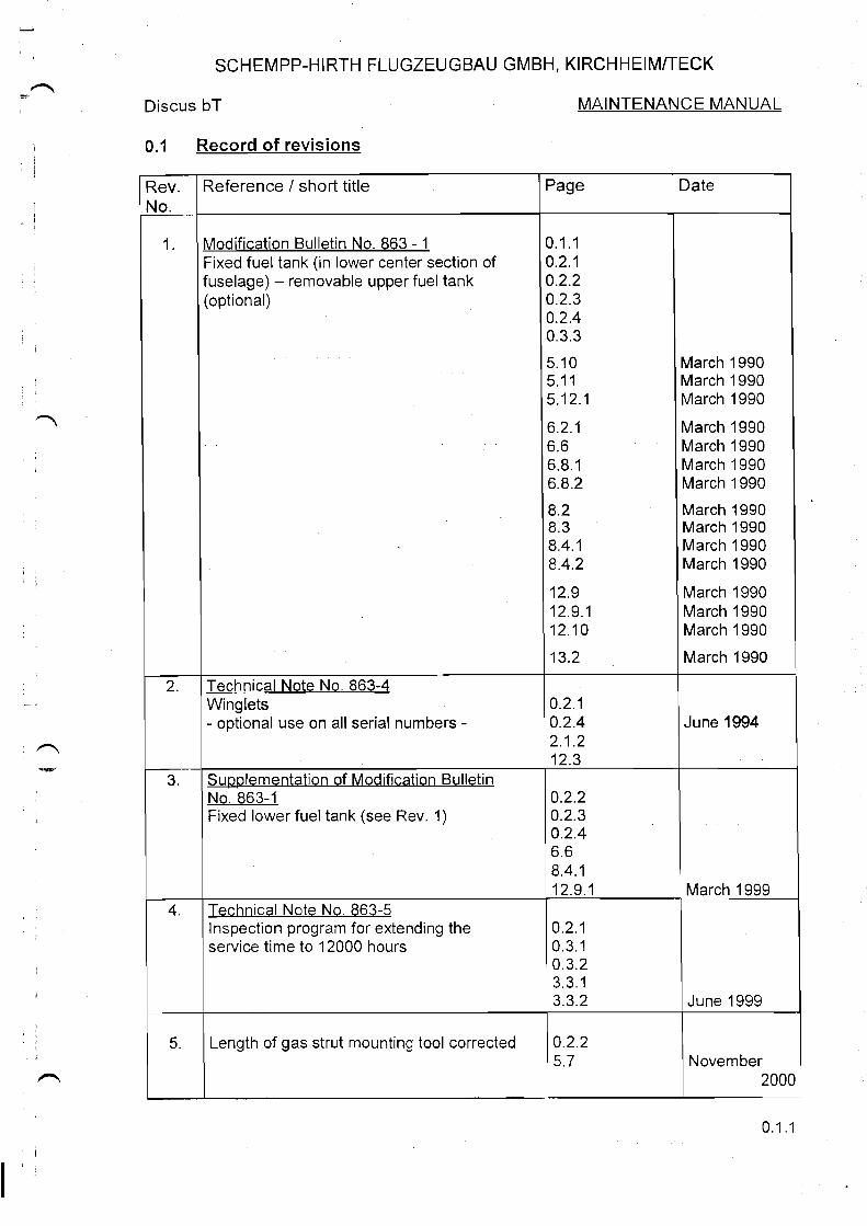
Discus bT MAINTENANCE MANUAL issue October 1989 0.1 Record of revisions Rev. No.
Reference / short title Page Date
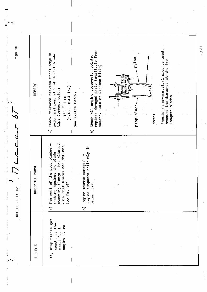
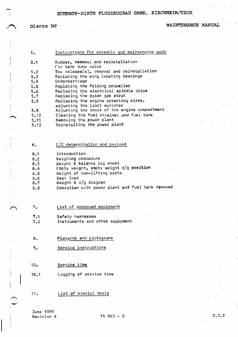
6.
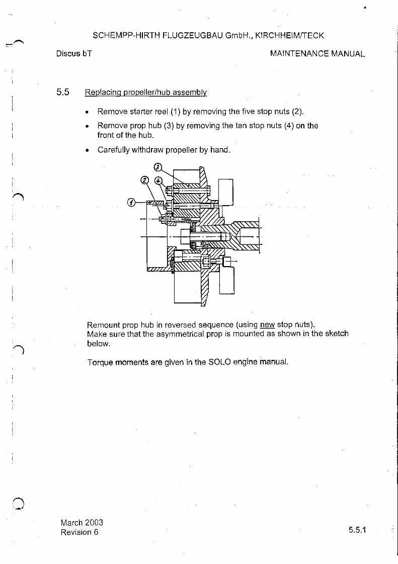
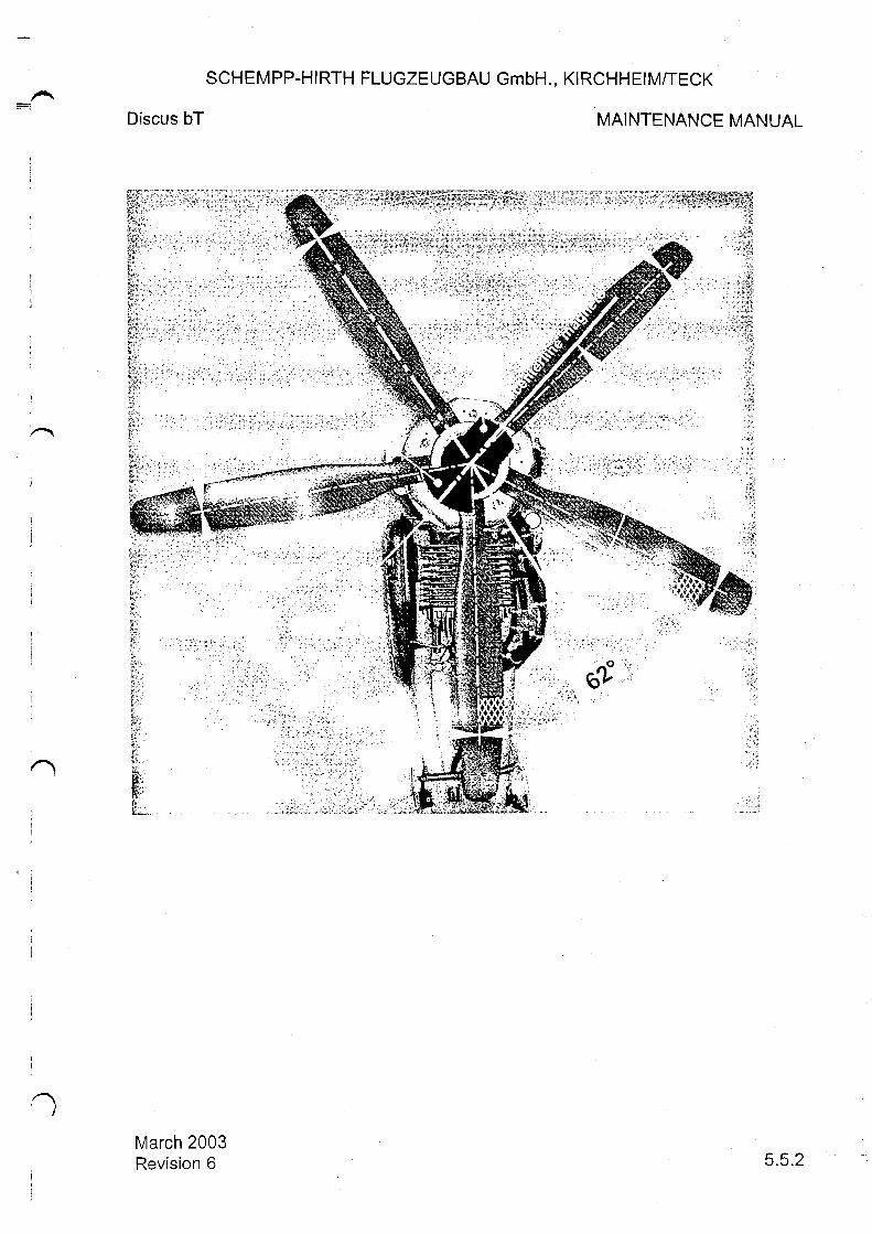
Replacing propeller/hub assembly
0.2.1 0.2.2 5.5.1 5.5.2
March 2003
7.
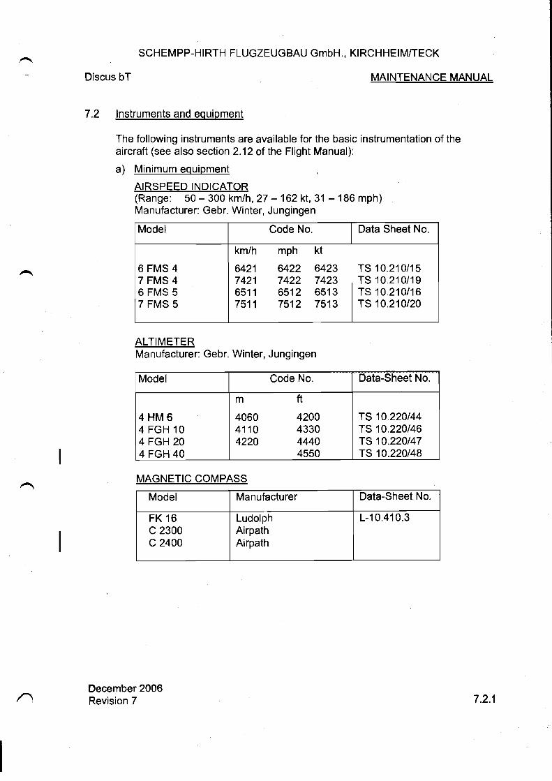
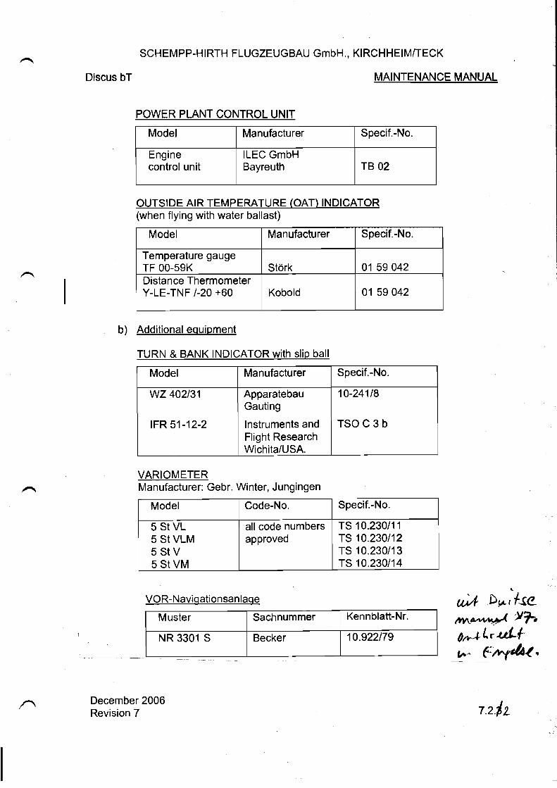
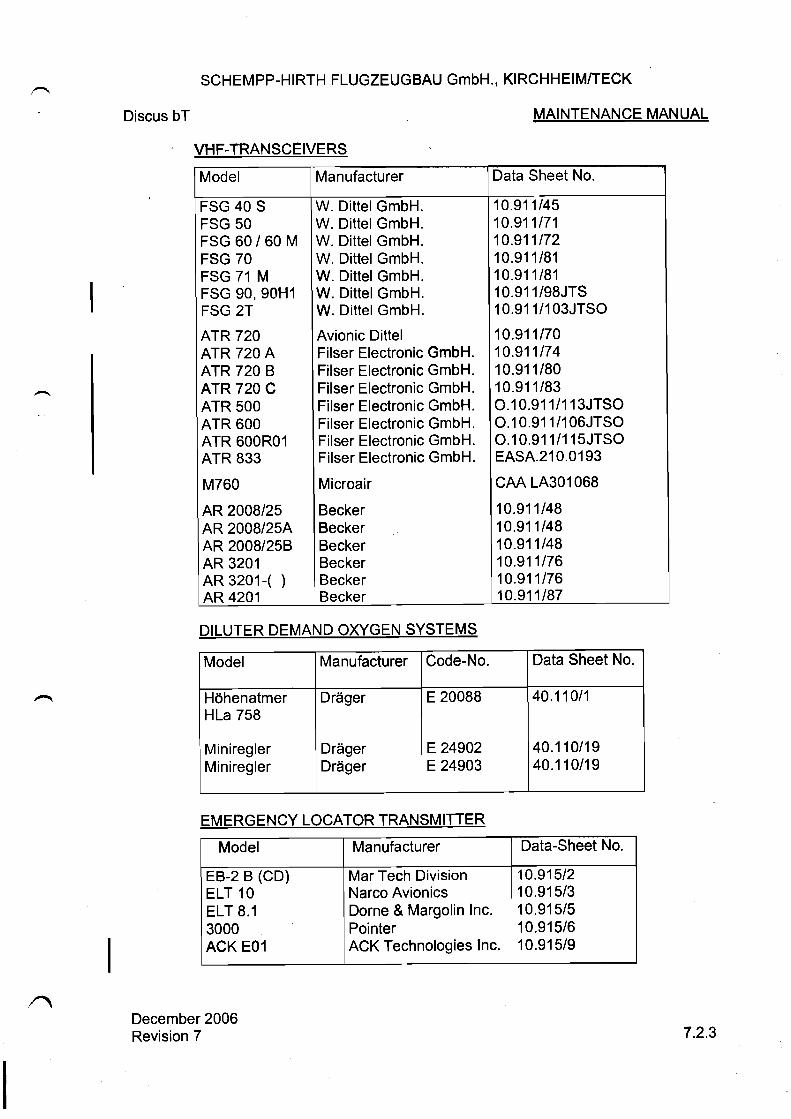
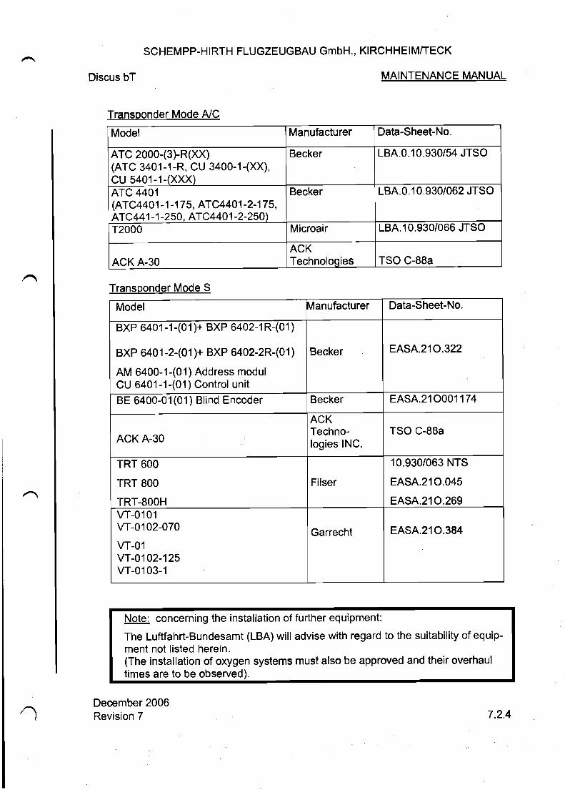
Supplement of equipment and instruments
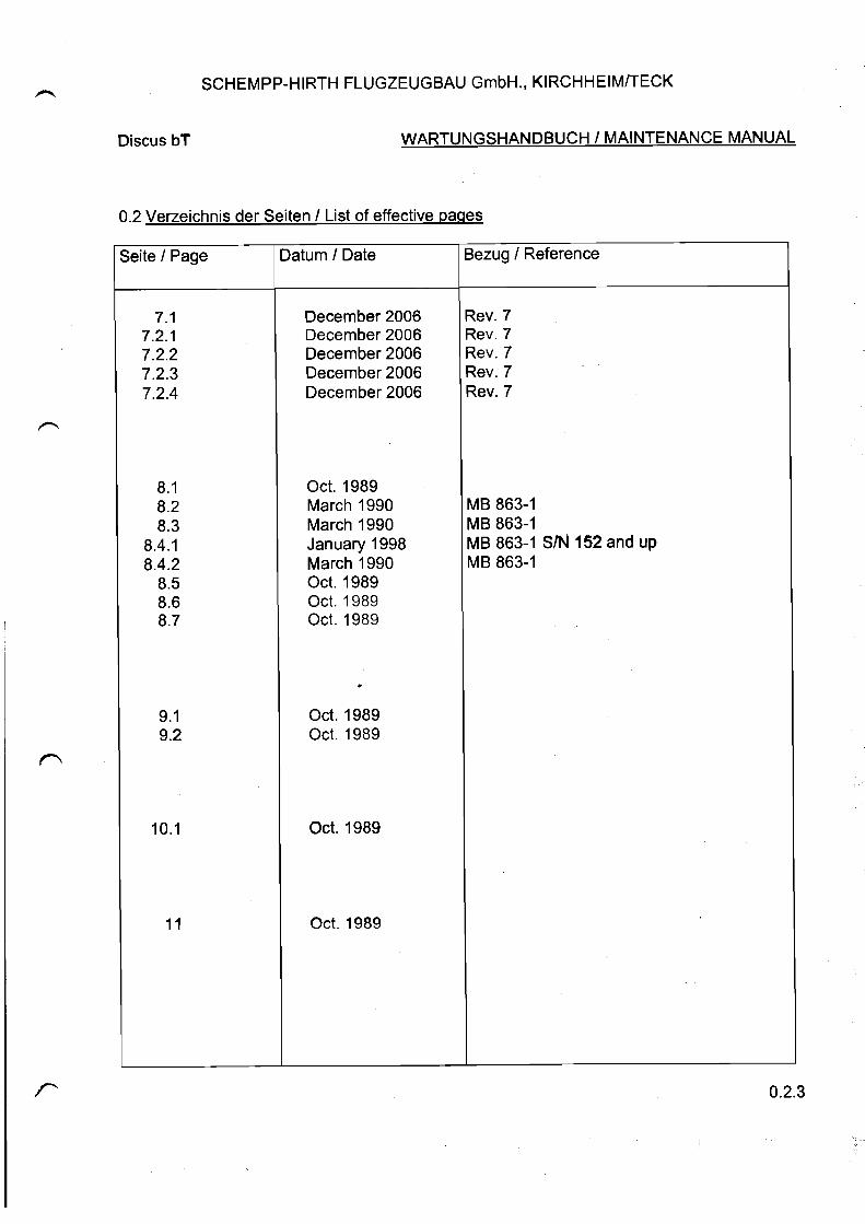
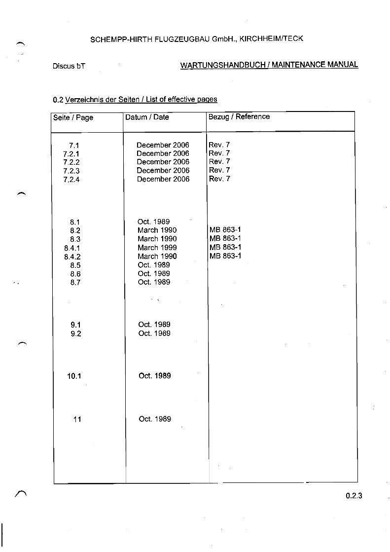
0.2.3 7.1 7.2.1 7.2.2 7.2.3 7.2.4
December 2006
8.
Technical Note 863-21 Engine pylon
0.2.2 0.2.4 5.11 5.12.1 5.12.2 12.9 13.1 Troubleshooting page 5
January 2011
Note: Cross out revisions which are not included. The list of effective pages must be amended by hand if necessary.
0.1.2


SCHEMPP-HIRTH FLUGZEUGBAU GmbH., KIRCHHEIM/TECK
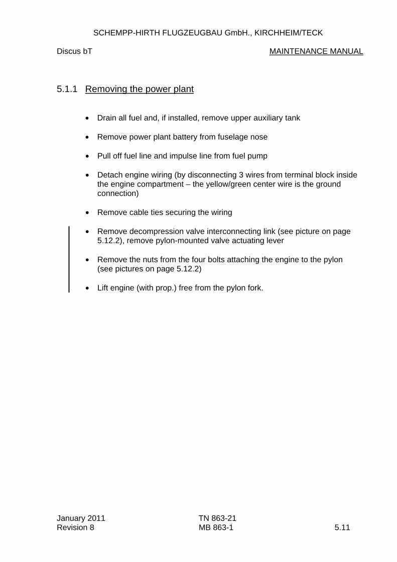
Discus bT MAINTENANCE MANUAL 5.1.1 Removing the power plant
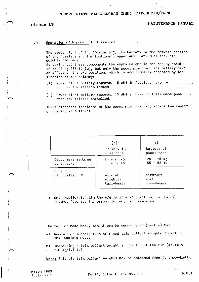
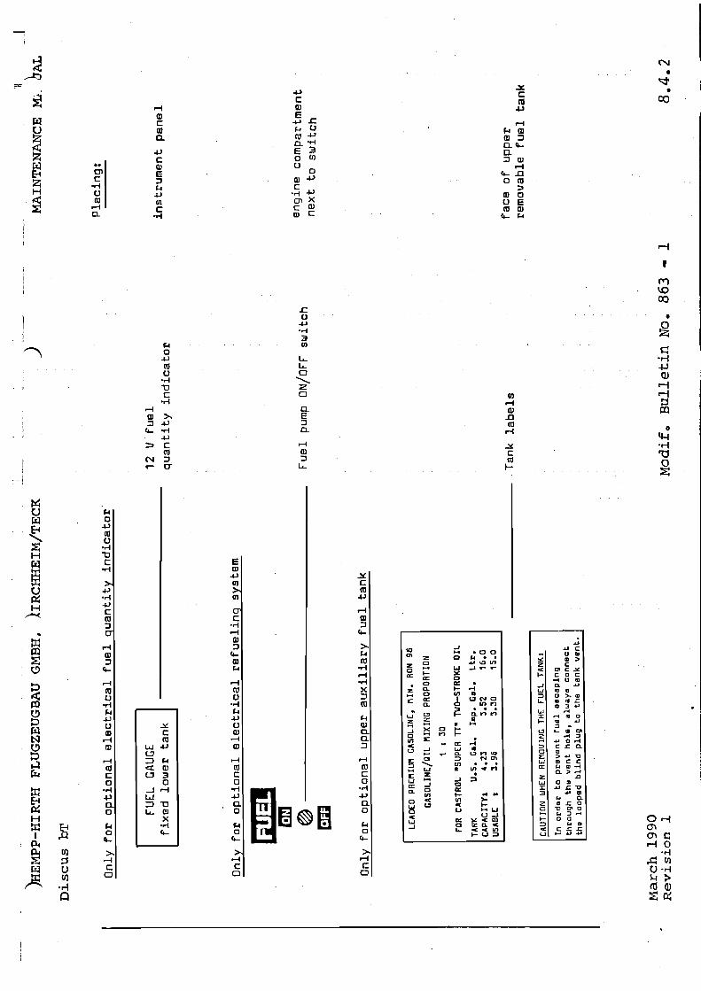
Drain all fuel and, if installed, remove upper auxiliary tank
Remove power plant battery from fuselage nose
Pull off fuel line and impulse line from fuel pump
Detach engine wiring (by disconnecting 3 wires from terminal block inside
the engine compartment – the yellow/green center wire is the ground connection)
Remove cable ties securing the wiring
Remove decompression valve interconnecting link (see picture on page
5.12.2), remove pylon-mounted valve actuating lever
Remove the nuts from the four bolts attaching the engine to the pylon (see pictures on page 5.12.2)
Lift engine (with prop.) free from the pylon fork.
January 2011 TN 863-21 Revision 8 MB 863-1 5.11
SCHEMPP-HIRTH FLUGZEUGBAU GmbH., KIRCHHEIM/TECK
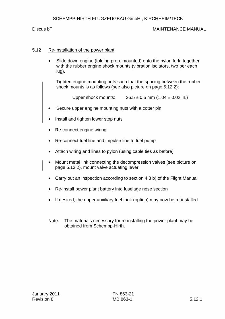
Discus bT MAINTENANCE MANUAL 5.12 Re-installation of the power plant
Slide down engine (folding prop. mounted) onto the pylon fork, together with the rubber engine shock mounts (vibration isolators, two per each lug).
Tighten engine mounting nuts such that the spacing between the rubber shock mounts is as follows (see also picture on page 5.12.2): Upper shock mounts: 26.5 ± 0.5 mm (1.04 ± 0.02 in.)
Secure upper engine mounting nuts with a cotter pin
Install and tighten lower stop nuts
Re-connect engine wiring Re-connect fuel line and impulse line to fuel pump
Attach wiring and lines to pylon (using cable ties as before)
Mount metal link connecting the decompression valves (see picture on
page 5.12.2), mount valve actuating lever
Carry out an inspection according to section 4.3 b) of the Flight Manual Re-install power plant battery into fuselage nose section
If desired, the upper auxiliary fuel tank (option) may now be re-installed
Note: The materials necessary for re-installing the power plant may be obtained from Schempp-Hirth.
January 2011 TN 863-21 Revision 8 MB 863-1 5.12.1

SCHEMPP-HIRTH FLUGZEUGBAU GmbH., KIRCHHEIM/TECK
Discus bT MAINTENANCE MANUAL Pictures for power plant removal and re-installation
January 2011 TN 863-21 Revision 8 5.12.2
M03
RT
841
January2011
Techn.
Note
No.
863-21
Maintenance
Manual
Diagram
9 12.9
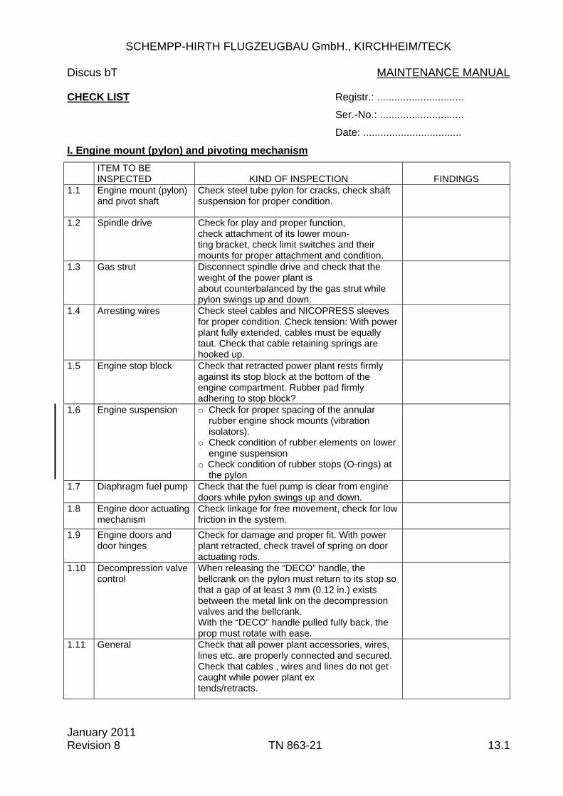
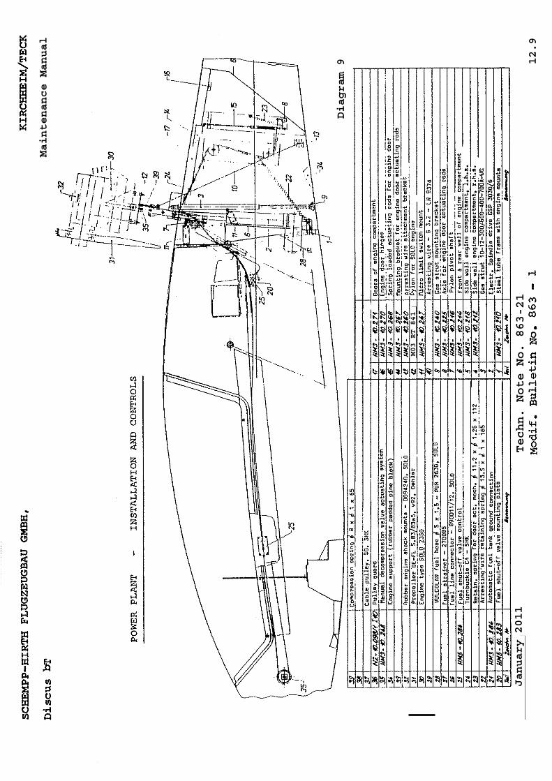
SCHEMPP-HIRTH FLUGZEUGBAU GmbH., KIRCHHEIM/TECK Discus bT MAINTENANCE MANUAL CHECK LIST Registr.: ..............................
Ser.-No.: .............................
Date: ..................................
I. Engine mount (pylon) and pivoting mechanism ITEM TO BE
INSPECTED
KIND OF INSPECTION
FINDINGS 1.1 Engine mount (pylon)
and pivot shaft Check steel tube pylon for cracks, check shaft suspension for proper condition.
1.2 Spindle drive Check for play and proper function, check attachment of its lower moun- ting bracket, check limit switches and their mounts for proper attachment and condition.
1.3 Gas strut Disconnect spindle drive and check that the weight of the power plant is about counterbalanced by the gas strut while pylon swings up and down.
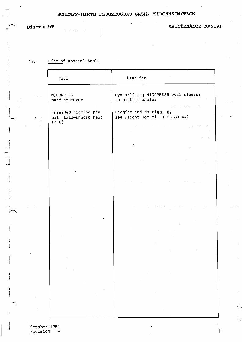
1.4 Arresting wires Check steel cables and NICOPRESS sleeves for proper condition. Check tension: With power plant fully extended, cables must be equally taut. Check that cable retaining springs are hooked up.
1.5 Engine stop block Check that retracted power plant rests firmly against its stop block at the bottom of the engine compartment. Rubber pad firmly adhering to stop block?
1.6 Engine suspension o Check for proper spacing of the annular rubber engine shock mounts (vibration isolators).
o Check condition of rubber elements on lower engine suspension
o Check condition of rubber stops (O-rings) at the pylon
1.7 Diaphragm fuel pump Check that the fuel pump is clear from engine doors while pylon swings up and down.
1.8 Engine door actuating mechanism
Check linkage for free movement, check for low friction in the system.
1.9 Engine doors and door hinges
Check for damage and proper fit. With power plant retracted, check travel of spring on door actuating rods.
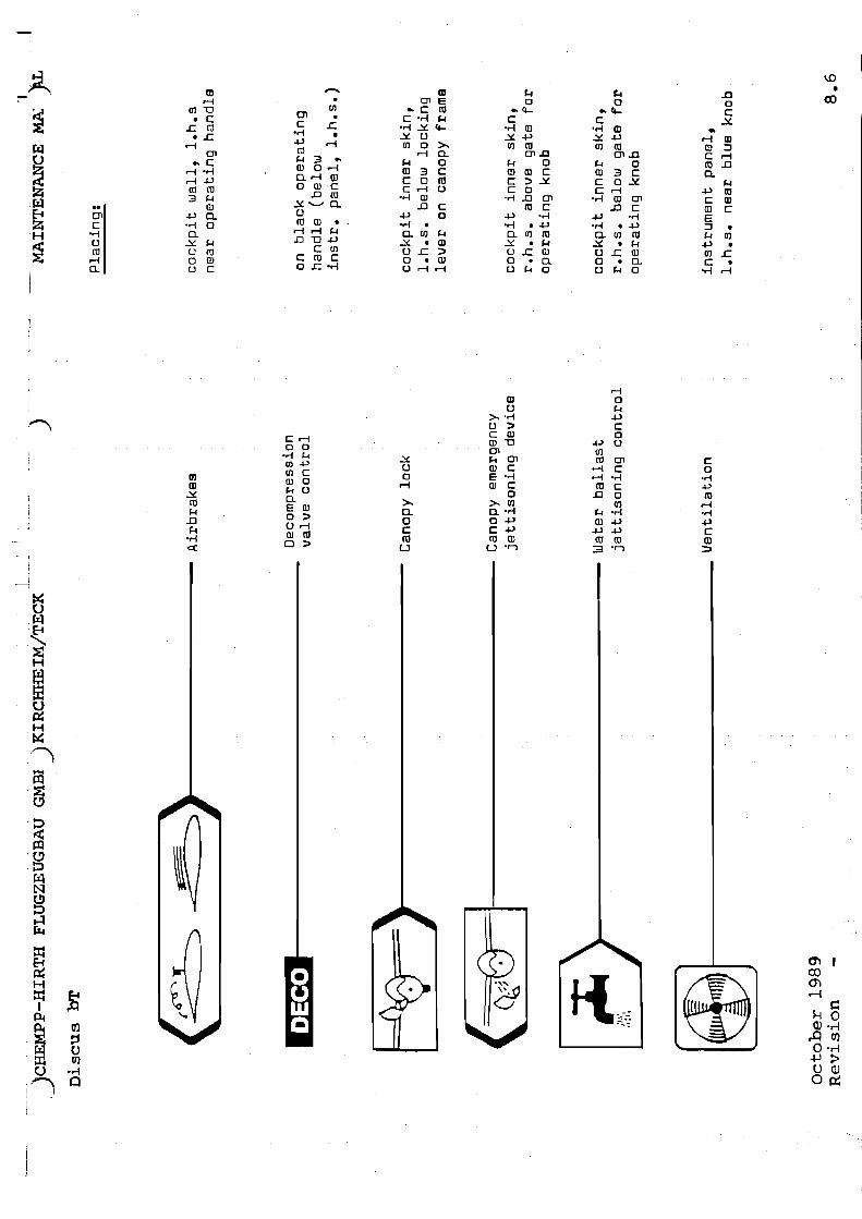
1.10 Decompression valve control
When releasing the “DECO” handle, the bellcrank on the pylon must return to its stop so that a gap of at least 3 mm (0.12 in.) exists between the metal link on the decompression valves and the bellcrank. With the “DECO” handle pulled fully back, the prop must rotate with ease.
1.11 General Check that all power plant accessories, wires, lines etc. are properly connected and secured. Check that cables , wires and lines do not get caught while power plant ex tends/retracts.
January 2011 Revision 8 TN 863-21 13.1
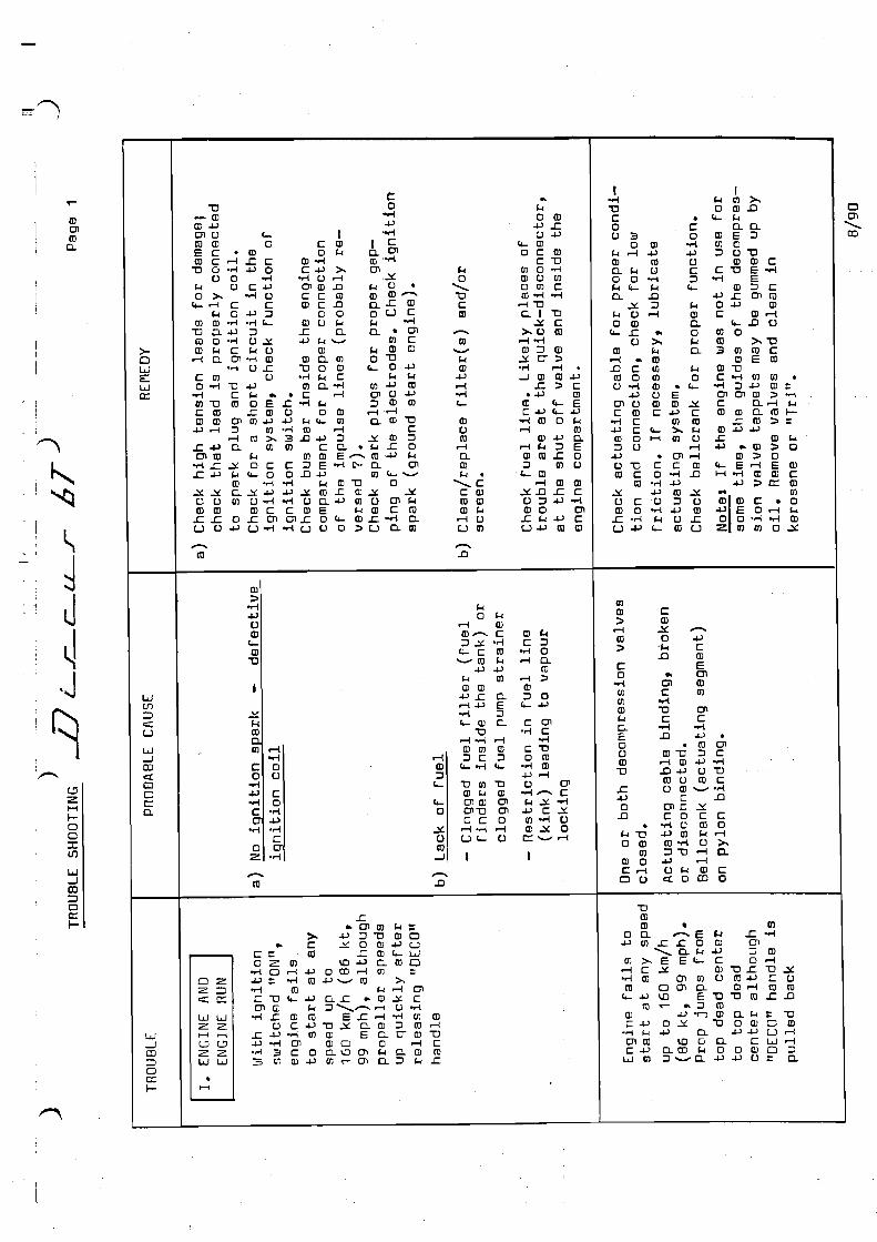
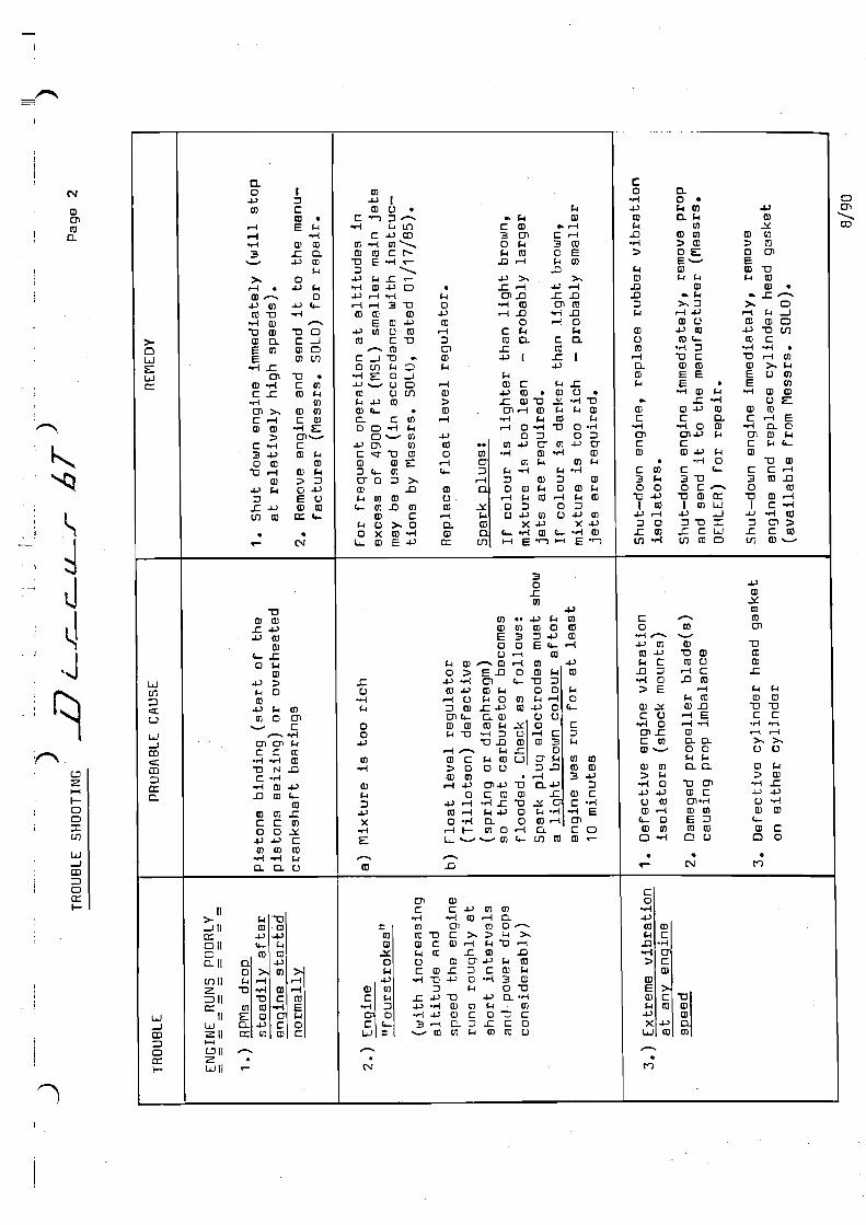
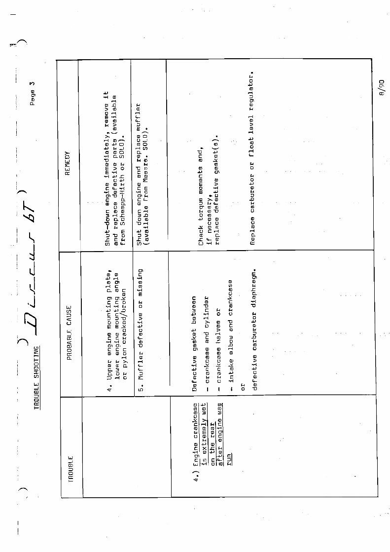
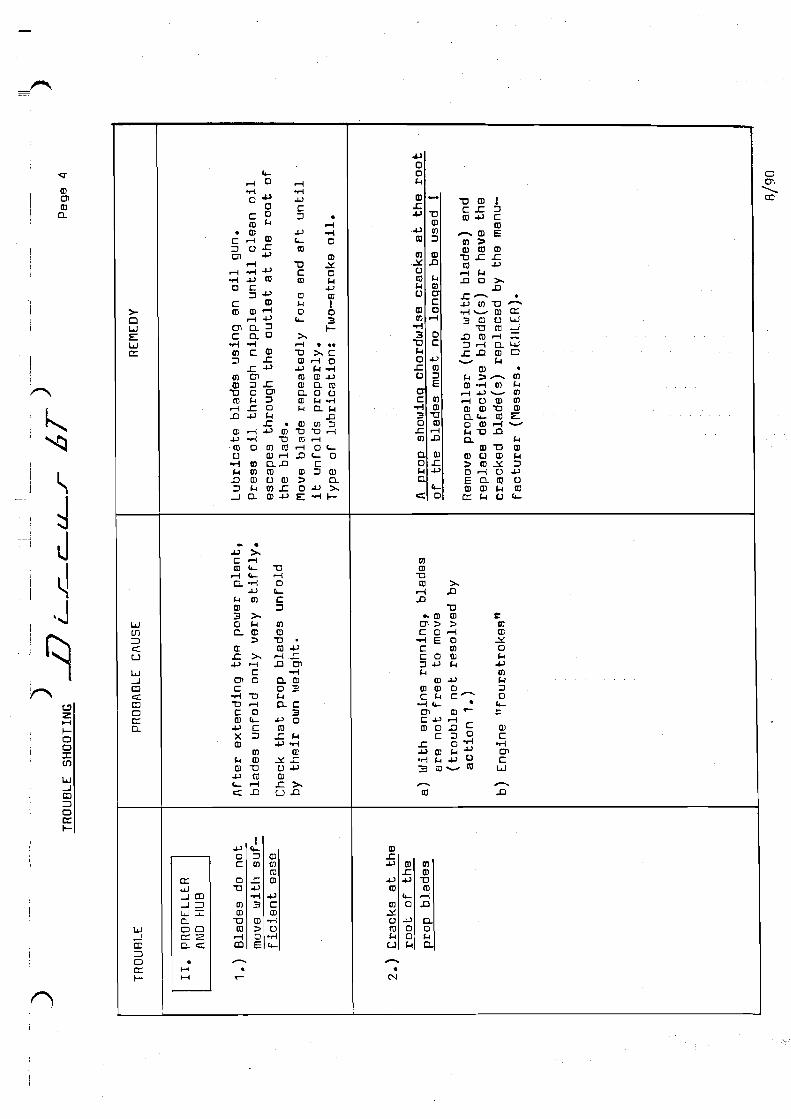
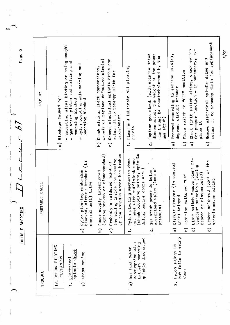
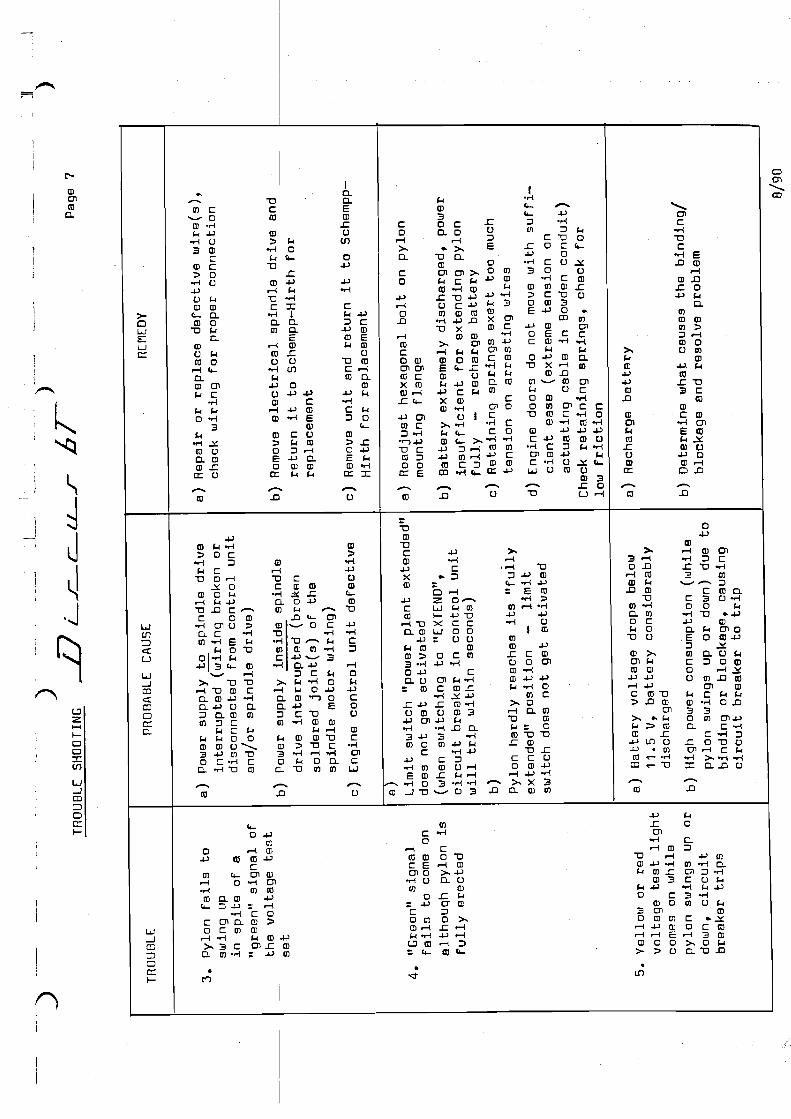
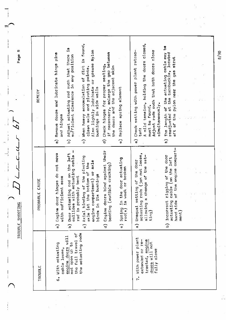
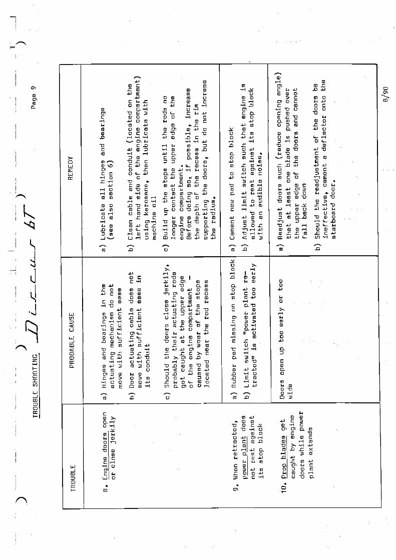
TRO
UB
LE S
HO
OTI
NG
D
iscu
s bT
P
age
5 Ja
nuar
y 20
11
TN 8
63-2
1
TRO
UB
LE
PR
OB
AB
LE C
AU
SE
RE
ME
DY
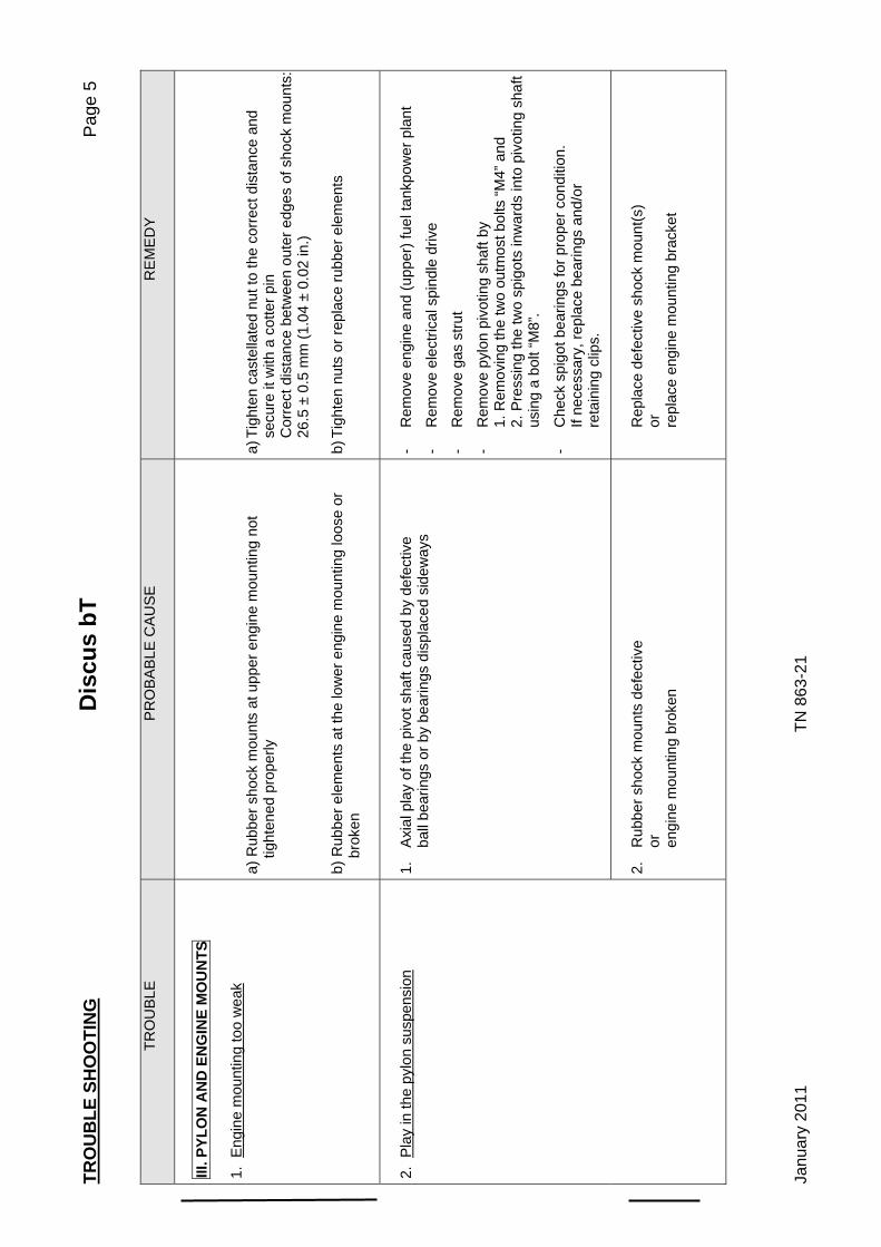
III. P
YLO
N A
ND
EN
GIN
E M
OU
NTS
1.
Eng
ine
mou
ntin
g to
o w
eak
a) R
ubbe
r sho
ck m
ount
s at
upp
er e
ngin
e m
ount
ing
not
tight
ened
pro
perly
b)
Rub
ber e
lem
ents
at t
he lo
wer
eng
ine
mou
ntin
g lo
ose
or
brok
en
a) T
ight
en c
aste
llate
d nu
t to
the
corr
ect d
ista
nce
and
secu
re it
with
a c
otte
r pin
C
orre
ct d
ista
nce
betw
een
oute
r edg
es o
f sho
ck m
ount
s:
26.5
± 0
.5 m
m (1
.04
± 0.
02 in
.) b)
Tig
hten
nut
s or
repl
ace
rubb
er e
lem
ents
2. P
lay
in th
e py
lon
susp
ensi
on
1.
Axi
al p
lay
of th
e pi
vot s
haft
caus
ed b
y de
fect
ive
ba
ll be
arin
gs o
r by
bear
ings
dis
plac
ed s
idew
ays
- R
emov
e en
gine
and
(upp
er) f
uel t
ankp
ower
pla
nt
- R
emov
e el
ectri
cal s
pind
le d
rive
- R
emov
e ga
s st
rut
- R
emov
e py
lon
pivo
ting
shaf
t by
1. R
emov
ing
the
two
outm
ost b
olts
“M4”
and
2. P
ress
ing
the
two
spig
ots
inw
ards
into
piv
otin
g sh
aft
us
ing
a bo
lt “M
8”.
- C
heck
spi
got b
earin
gs fo
r pro
per c
ondi
tion.
If ne
cess
ary,
repl
ace
bear
ings
and
/or
re
tain
ing
clip
s.
2.
Rub
ber s
hock
mou
nts
defe
ctiv
e
or
engi
ne m
ount
ing
brok
en
R
epla
ce d
efec
tive
shoc
k m
ount
(s)
or
repl
ace
engi
ne m
ount
ing
brac
ket