Embed Size (px)
Citation preview
Directivity patterns and pulse profiles of ultrasound emitted by laser action on interfacebetween transparent and opaque solids: Analytical theorySergey M. Nikitin, Vincent Tournat, Nikolay Chigarev, Alain Bulou, Bernard Castagnede, Andreas Zerr, and
Vitalyi Gusev
Citation: Journal of Applied Physics 115, 044902 (2014); doi: 10.1063/1.4861882 View online: http://dx.doi.org/10.1063/1.4861882 View Table of Contents: http://scitation.aip.org/content/aip/journal/jap/115/4?ver=pdfcov Published by the AIP Publishing Articles you may be interested in Finite element calculations of the time dependent thermal fluxes in the laser-heated diamond anvil cell J. Appl. Phys. 111, 112617 (2012); 10.1063/1.4726231 Generation of inhomogeneous plane shear acoustic modes by laser-induced thermoelastic gratings at theinterface of transparent and opaque solids J. Appl. Phys. 110, 123526 (2011); 10.1063/1.3662921 Effect of laser beam incidence angle on the thermoelastic generation in semi-transparent materials J. Acoust. Soc. Am. 130, 3691 (2011); 10.1121/1.3658384 Two dimensional hydrodynamic simulation of high pressures induced by high power nanosecond laser-matterinteractions under water J. Appl. Phys. 101, 103514 (2007); 10.1063/1.2734538 Nanosecond time-resolved multiprobe imaging of laser damage in transparent solids Appl. Phys. Lett. 81, 3149 (2002); 10.1063/1.1511536
[This article is copyrighted as indicated in the article. Reuse of AIP content is subject to the terms at: http://scitation.aip.org/termsconditions. Downloaded to ] IP:
149.150.51.237 On: Mon, 15 Sep 2014 22:50:52
Directivity patterns and pulse profiles of ultrasound emitted by laser actionon interface between transparent and opaque solids: Analytical theory
Sergey M. Nikitin,1,2,3,a) Vincent Tournat,1 Nikolay Chigarev,1 Alain Bulou,2
Bernard Castagnede,1 Andreas Zerr,3 and Vitalyi Gusev1,a)
1LAUM, UMR-CNRS 6613, Universit�e du Maine, 72085 Le Mans, France2IMMM, UMR-CNRS 6283, Universit�e du Maine, 72085 Le Mans, France3LSPM, UPR-CNRS 3407, Universit�e Paris Nord, 93430 Villetaneuse, France
(Received 29 October 2013; accepted 27 December 2013; published online 22 January 2014)
The analytical theory for the directivity patterns of ultrasounds emitted from laser-irradiated
interface between two isotropic solids is developed. It is valid for arbitrary combinations of
transparent and opaque materials. The directivity patterns are derived both in two-dimensional and
in three-dimensional geometries, by accounting for the specific features of the sound generation by
the photo-induced mechanical stresses distributed in the volume, essential in the laser ultrasonics.
In particular, the theory accounts for the contribution to the emitted propagating acoustic fields
from the converted by the interface evanescent photo-generated compression-dilatation waves. The
precise analytical solutions for the profiles of longitudinal and shear acoustic pulses emitted in
different directions are proposed. The developed theory can be applied for dimensional scaling,
optimization, and interpretation of the high-pressure laser ultrasonics experiments in diamond anvil
cell. VC 2014 AIP Publishing LLC. [http://dx.doi.org/10.1063/1.4861882]
I. INTRODUCTION
In the recent years, the application of all-optical non-
contact laser ultrasonics (LU) techniques for the evaluation
of compressed material properties, through high pressure
experiments in a diamond anvil cell (DAC) on samples with
characteristic dimensions between 10 and 100 lm, attracted
an increasing number of researchers.1–6 While picosecond
laser ultrasonics, based on the application of a femtosecond
laser, uses generation and detection of acoustic waves propa-
gating quasi-collinear to the DAC axis,1 the point-source-
point-receiver technique,2,3 and line-source-point-receiver
technique,4,5 based on the application of sharply focused
radiation of sub-nanosecond laser, are monitoring the longi-
tudinal and shear acoustic waves propagating at rather large
angles to this axis. Thus, for the latter two LU-DAC techni-
ques, the knowledge of the directivity patterns of acoustical
waves, emitted from laser-irradiated interface between trans-
parent materials (e.g. diamond or pressure medium such as
KBr or argon) and light-absorbing materials (e.g. metals),
could be useful for scaling and interpretation of the experi-
ments on sound waves propagation in metals and transparent
media compressed in a DAC.
Earlier, both theoretical and experimental studies of
the directivity patterns of laser ultrasound in solids mostly
concentrated on the case when laser irradiates a mechani-
cally free surface of a solid halfspace.6–18 Directivity pat-
terns were evaluated both for the compression/dilatation
and for the shear acoustic waves. The influence on the di-
rectivity patterns of the thermal conductivity of the solid,12
and the laser focusing and laser penetration depth in the
solid13,14 were investigated. The profiles of the emitted
acoustic pulses were the subject of the analysis both in the
case of longitudinal and of shear acoustic waves.10,11,15,16
These research activities had been initiated and were
continuously supported by the applications of laser ultra-
sound for the non-destructive testing of the materials and
structures,7 and the investigations of the directivity pat-
terns of laser ultrasound emitted from a mechanically free
surface are continuing for some specific applications until
now.17,18
The investigations of the directivity patterns of laser
ultrasound emitted from an interface between an optically
transparent and an optically opaque solids have been fueled
by the applications of laser ultrasound in high pressure
research, which started just a few years ago.1–5 Recently, the
directivity patterns of longitudinal and shear acoustic waves
emitted by focusing laser radiation at the interface of dia-
mond with aluminum have been simulated for the first time
numerically.19 Here, we present the analytical descriptions
for the directivity patterns of laser ultrasound, which are
valid for arbitrary combinations of transparent and opaque
materials. The directivity patterns are derived as particular
cases of the known general solution for the acoustic fields
generated by laser radiation in layered media,20,21 by
accounting for the specific features of the sound generation
by thermo-elastic stresses distributed in the volume, which
are essential for laser ultrasonics. We also present the analyt-
ical solutions for the profiles of the longitudinal and shear
acoustic pulses emitted in different directions. The derived
mathematical formulas provide straight opportunity to pre-
dict the acoustic field, which is formed in the diamond anvil
cell after photo-generation and several reflections of bulk
acoustic waves at the interfaces relevant for the experiments
in DAC.
a)Authors to whom correspondence should be addressed. Electronic
addresses: [email protected] and vitali.goussev@univ-
lemans.fr
0021-8979/2014/115(4)/044902/15/$30.00 VC 2014 AIP Publishing LLC115, 044902-1
JOURNAL OF APPLIED PHYSICS 115, 044902 (2014)
[This article is copyrighted as indicated in the article. Reuse of AIP content is subject to the terms at: http://scitation.aip.org/termsconditions. Downloaded to ] IP:
149.150.51.237 On: Mon, 15 Sep 2014 22:50:52
II. GENERAL THEORETICAL DESCRIPTION OF THELASER ULTRASOUND DIRECTIVITY PATTERN
In order to derive an analytical presentation of the direc-
tivity patterns of the acoustic waves when the laser radiation
is incident from the transparent media “(2)” onto its plane
interface with the light-absorbing media “(1)” (Fig. 1), we use
the general solution obtained for the optoacoustic transforma-
tion at these type of interfaces in Ref. 21. We present mathe-
matical formalism for the case of two-dimensional (2D)
geometry, which is experimentally realized by focusing laser
radiation into a stripe with the length significantly exceeding
its width. The generalization of mathematical approach for the
case of three-dimensional (3D) geometry, which is experi-
mentally realized by focusing laser radiation into a circular
spot, is presented in Appendix A. For definiteness, we analyze
the directivity patterns of acoustic waves in medium “(1),”
because the solutions for the medium “(2)” can be obtained
by symmetry principles. If the origin of the coordinate system
is chosen at the interface of media “(1)” and “(2)” and z-axis
is perpendicular to the interface and directed toward media
“(1),” the solutions for the Fourier spectra of scalar / and vec-
tor w acoustic potentials (Eqs. (13) and (15) from Ref. 21),
which satisfy the conditions of continuity of the mechanical
displacements and stresses at the interface and the conditions
of radiation in the far field,22–24 are
~~/1ðx; kx; zÞ ¼�i
2a1
~~~rin1 ðx; kx;a1Þ þ R11
ll
~~~rin1 ðx; kx;�a1Þ
�
þa1
a2
T21ll
~~~rin2 ðx; kx;a2Þ
�e�ia1z � ~~/1ðx; kxÞe�ia1z;
(1)
~~w1ðx; kx; zÞ ¼�i
2a1
R11lt
~~~rin1ðx; kx;�a1Þ
�
þa1
a2
T21lt
~~~rin2ðx; kx;a2Þ
�e�ib1z � ~~w1ðx; kxÞe�ib1z:
(2)
The Fourier transforms for the derivation and manipulation
of the solutions in Eqs. (1) and (2) are defined by
~~~Fðx; kx; kzÞ ¼ð1�1
ð1�1
ð1�1
Fðt; x; zÞe�iðxt�kxx�kzzÞdtdxdz;
Fðt; x; zÞ ¼ 1
ð2pÞ3ð1�1
ð1�1
ð1�1
~~~Fðx; kx; kzÞeiðxt�kxx�kzzÞdxdkxdkz:
(3)
In Eqs. (1) and (2), x is the cyclic frequency of the laser-
induced normalized stress fields rin1;2 and of the acoustic fields,
kx is the projection of the acoustic wave vectors on the x-axis,
which is in the plane of the interface. We remind here that
photo-induced thermo-elastic stress tensor rikl is isotropic in iso-
tropic and cubic solids, i.e., rikl � ridkl. Note that
x-components of the wave vectors are equal for longitudinal and
shear waves and also in both media22,24 (see Fig. 1), while the
z-components are different. i.e., kzl1;2 � a1;2 ¼ffiffiffiffiffiffiffiffiffiffiffiffiffiffiffiffiffiffik2
l1;2 � k2x
qand
kzt1;2 � b1;2 ¼ffiffiffiffiffiffiffiffiffiffiffiffiffiffiffiffiffiffik2
t1;2 � k2x
q, where sgnðRea1;2Þ ¼ sgnðReb1;2Þ
¼ sgnðxÞ for real a1;2 and b1;2 and sgnðIma1;2Þ ¼ sgnðImb1;2Þ¼ �1 for imaginary a1;2 and b1;2. Here, x=tl1;2 � kl1;2 and
x=tt1;2 � kt1;2 are the wave numbers of the compression/dila-
tion and shear acoustic waves in medium “1” and medium “2,”
with tl1;2 and tt1;2 denoting the velocities of the longitudinal
and shear waves, respectively. Although the physical nature of
laser-induced stresses in Eqs. (1) and (2) is not specified yet,
below we analyze the case of thermoelastic stresses caused by
laser heating of the media. They are normalized on the longitu-
dinal moduli of the corresponding media, rin1;2 ¼ ri
1;2=
ðq1;2t2l1;2Þ, where q1;2 are the densities. Although solutions (1)
and (2), borrowed from Ref. 21, are written for the two-
dimensional problem and are well-suited only for the line-
source-point-receiver LU-DAC technique,4,5 the extension of
the general solution to the three-dimensional case is straightfor-
ward (Appendix A).
The solutions in Eqs. (1) and (2) have a clear transparent
physical sense. They account for the fact that the stresses are
induced by laser radiation, in general, in both contacting
media. They also account for the fact that thermo-elastic
stress in isotropic media can generate only compression/dila-
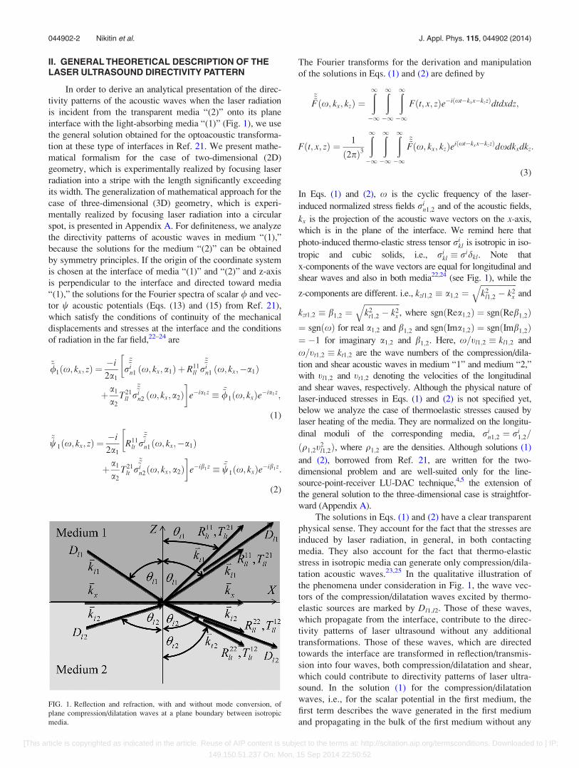
tation acoustic waves.23,25 In the qualitative illustration of
the phenomena under consideration in Fig. 1, the wave vec-
tors of the compression/dilatation waves excited by thermo-
elastic sources are marked by Dl1,l2. Those of these waves,
which propagate from the interface, contribute to the direc-
tivity patterns of laser ultrasound without any additional
transformations. Those of these waves, which are directed
towards the interface are transformed in reflection/transmis-
sion into four waves, both compression/dilatation and shear,
which could contribute to directivity patterns of laser ultra-
sound. In the solution (1) for the compression/dilatation
waves, i.e., for the scalar potential in the first medium, the
first term describes the wave generated in the first medium
and propagating in the bulk of the first medium without any
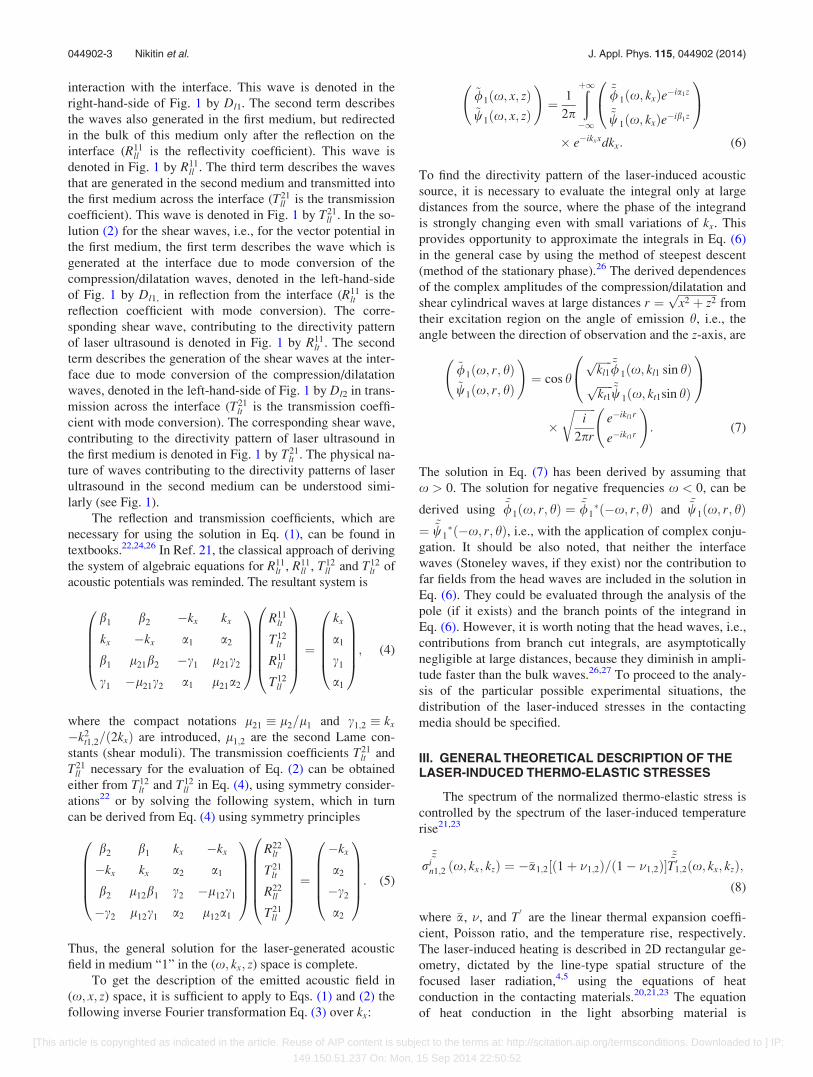
FIG. 1. Reflection and refraction, with and without mode conversion, of
plane compression/dilatation waves at a plane boundary between isotropic
media.
044902-2 Nikitin et al. J. Appl. Phys. 115, 044902 (2014)
[This article is copyrighted as indicated in the article. Reuse of AIP content is subject to the terms at: http://scitation.aip.org/termsconditions. Downloaded to ] IP:
149.150.51.237 On: Mon, 15 Sep 2014 22:50:52
interaction with the interface. This wave is denoted in the
right-hand-side of Fig. 1 by Dl1. The second term describes
the waves also generated in the first medium, but redirected
in the bulk of this medium only after the reflection on the
interface (R11ll is the reflectivity coefficient). This wave is
denoted in Fig. 1 by R11ll . The third term describes the waves
that are generated in the second medium and transmitted into
the first medium across the interface (T21ll is the transmission
coefficient). This wave is denoted in Fig. 1 by T21ll . In the so-
lution (2) for the shear waves, i.e., for the vector potential in
the first medium, the first term describes the wave which is
generated at the interface due to mode conversion of the
compression/dilatation waves, denoted in the left-hand-side
of Fig. 1 by Dl1, in reflection from the interface (R11lt is the
reflection coefficient with mode conversion). The corre-
sponding shear wave, contributing to the directivity pattern
of laser ultrasound is denoted in Fig. 1 by R11lt . The second
term describes the generation of the shear waves at the inter-
face due to mode conversion of the compression/dilatation
waves, denoted in the left-hand-side of Fig. 1 by Dl2 in trans-
mission across the interface (T21lt is the transmission coeffi-
cient with mode conversion). The corresponding shear wave,
contributing to the directivity pattern of laser ultrasound in
the first medium is denoted in Fig. 1 by T21lt . The physical na-
ture of waves contributing to the directivity patterns of laser
ultrasound in the second medium can be understood simi-
larly (see Fig. 1).
The reflection and transmission coefficients, which are
necessary for using the solution in Eq. (1), can be found in
textbooks.22,24,26 In Ref. 21, the classical approach of deriving
the system of algebraic equations for R11lt , R11
ll , T12ll and T12
lt of
acoustic potentials was reminded. The resultant system is
b1 b2 �kx kx
kx �kx a1 a2
b1 l21b2 �c1 l21c2
c1 �l21c2 a1 l21a2
0BBBB@
1CCCCA
R11lt
T12lt
R11ll
T12ll
0BBBBB@
1CCCCCA ¼
kx
a1
c1
a1
0BBBB@
1CCCCA; (4)
where the compact notations l21 � l2=l1 and c1;2 � kx
�k2t1;2=ð2kxÞ are introduced, l1;2 are the second Lame con-
stants (shear moduli). The transmission coefficients T21lt and
T21ll necessary for the evaluation of Eq. (2) can be obtained
either from T12lt and T12
ll in Eq. (4), using symmetry consider-
ations22 or by solving the following system, which in turn
can be derived from Eq. (4) using symmetry principles
b2 b1 kx �kx
�kx kx a2 a1
b2 l12b1 c2 �l12c1
�c2 l12c1 a2 l12a1
0BBBB@
1CCCCA
R22lt
T21lt
R22ll
T21ll
0BBBBB@
1CCCCCA ¼
�kx
a2
�c2
a2
0BBBB@
1CCCCA: (5)
Thus, the general solution for the laser-generated acoustic
field in medium “1” in the (x; kx; z) space is complete.
To get the description of the emitted acoustic field in
(x; x; z) space, it is sufficient to apply to Eqs. (1) and (2) the
following inverse Fourier transformation Eq. (3) over kx:
~/1ðx; x; zÞ~w1ðx; x; zÞ
!¼ 1
2p
ðþ1�1
~~/1ðx; kxÞe�ia1z
~~w1ðx; kxÞe�ib1z
0@
1A
� e�ikxxdkx: (6)
To find the directivity pattern of the laser-induced acoustic
source, it is necessary to evaluate the integral only at large
distances from the source, where the phase of the integrand
is strongly changing even with small variations of kx. This
provides opportunity to approximate the integrals in Eq. (6)
in the general case by using the method of steepest descent
(method of the stationary phase).26 The derived dependences
of the complex amplitudes of the compression/dilatation and
shear cylindrical waves at large distances r ¼ffiffiffiffiffiffiffiffiffiffiffiffiffiffix2 þ z2p
from
their excitation region on the angle of emission h, i.e., the
angle between the direction of observation and the z-axis, are
~/1ðx; r; hÞ~w1ðx; r; hÞ
!¼ cos h
ffiffiffiffiffiffikl1
p ~~/1ðx; kl1 sin hÞffiffiffiffiffiffikt1
p ~~w1ðx; kt1sin hÞ
0@
1A
�ffiffiffiffiffiffiffiffi
i
2pr
re�ikl1r
e�ikt1r
!: (7)
The solution in Eq. (7) has been derived by assuming that
x > 0. The solution for negative frequencies x < 0, can be
derived using~~/1ðx; r; hÞ ¼
~~/1�ð�x; r; hÞ and
~~w1ðx; r; hÞ¼ ~~w1
�ð�x; r; hÞ, i.e., with the application of complex conju-
gation. It should be also noted, that neither the interface
waves (Stoneley waves, if they exist) nor the contribution to
far fields from the head waves are included in the solution in
Eq. (6). They could be evaluated through the analysis of the
pole (if it exists) and the branch points of the integrand in
Eq. (6). However, it is worth noting that the head waves, i.e.,
contributions from branch cut integrals, are asymptotically
negligible at large distances, because they diminish in ampli-
tude faster than the bulk waves.26,27 To proceed to the analy-
sis of the particular possible experimental situations, the
distribution of the laser-induced stresses in the contacting
media should be specified.
III. GENERAL THEORETICAL DESCRIPTION OF THELASER-INDUCED THERMO-ELASTIC STRESSES
The spectrum of the normalized thermo-elastic stress is
controlled by the spectrum of the laser-induced temperature
rise21,23
~~~rin1;2 ðx; kx; kzÞ ¼ ��a1;2½ð1þ �1;2Þ=ð1� �1;2Þ�
~~~T 01;2ðx; kx; kzÞ;(8)
where �a, �, and T0
are the linear thermal expansion coeffi-
cient, Poisson ratio, and the temperature rise, respectively.
The laser-induced heating is described in 2D rectangular ge-
ometry, dictated by the line-type spatial structure of the
focused laser radiation,4,5 using the equations of heat
conduction in the contacting materials.20,21,23 The equation
of heat conduction in the light absorbing material is
044902-3 Nikitin et al. J. Appl. Phys. 115, 044902 (2014)
[This article is copyrighted as indicated in the article. Reuse of AIP content is subject to the terms at: http://scitation.aip.org/termsconditions. Downloaded to ] IP:
149.150.51.237 On: Mon, 15 Sep 2014 22:50:52
inhomogeneous. The laser-induced heat release Q1ðt; x; zÞ in
the light-absorbing material, i.e., the increase in the material
thermal energy density per unit time in a unit volume, can be
presented in the form Q1 ¼ f ðtÞUðxÞWðzÞ,23,24 where the
function f ðtÞ describes the laser pulse intensity envelope in
time, the function UðxÞ describes the lateral distribution of
the absorbed laser energy release controlled by laser inten-
sity distribution at the irradiated surface, i.e., by focusing,
and the function WðzÞ describes the distribution of the
absorbed laser energy release in depth controlled by the opti-
cal penetration depth and some other physical parameters of
the light absorbing medium.23,25 The solution of the thermal
conductivity equations, satisfying the conditions of continu-
ity of the temperature and of the heat flux at the interface
between the opaque and the transparent media, can be
derived by the same method of integral transforms, which
has been applied in Ref. 21 to derive the solutions in Eqs. (1)
and (2) of the inhomogeneous wave equations. It is sufficient
to find the solution in the reciprocal Fourier spaces, where it
can be factorized in the following form:
~~~T 01;2ðx; kx; kzÞ � H1;2ðx; kx; kzÞ~f ðxÞ~UðkxÞ: (9)
The general expression of the function Hðx; kx; kzÞ is
H1ðx; kx; kzÞ ¼1
v1ðk2z � d2
1Þ~WðkzÞ þ
v1kz � v2d2
v1d1 þ v2d2
~Wð�d1Þ� �
;
H2ðx; kx; kzÞ ¼ð�1Þ
ðv1d1 þ v2d2Þðkz þ d2Þ~Wð�d1Þ:
(10)
Here, d1;2 �ffiffiffiffiffiffiffiffiffiffiffiffiffiffiffiffiffiffiffiffiffiffiffiffiffiffiffiffiffi�ix=D1;2 � k2
x
pcan be associated with the
projection of the thermal wave vectorffiffiffiffiffiffiffiffiffiffiffiffiffiffiffiffiffiffiffi�ix=D1;2
pon the
z-axis, D1;2 are the thermal diffusivities and v1;2 are the ther-
mal conductivities of the media in contact. It is worth men-
tioning here that if future experiments in DAC indicate the
importance of thermal boundary resistance at the interface
between the diamond and the sample, then the solution of
the heat conduction problem with modified interface condi-
tions for temperature field and heat flux could be still
obtained by the same mathematical formalism of integral
transforms.
The description of the laser-induced stresses presented
in Eqs. (8)–(10) finalizes the general solution for the ultra-
sound emission by thermoelastic sources. The specific
problems of interest for the practical analysis differ only by
the characteristics of the laser induced heat release
Q1 ¼ f ðtÞUðxÞWðzÞ. The common models for the laser pulse
intensity envelope, distribution of laser intensity across
the focus, and distribution of laser intensity in depth of
light absorbing medium are f ðtÞ ¼ exp½�ð2t=sLÞ2�; UðxÞ¼ exp½�ð2x=dÞ2�; WðzÞ ¼ ðI=lÞexpð�z=lÞ, respectively,
where sL is the laser pulse duration at 1/e level, d is the diam-
eter of the focus at 1/e level, I is the absorbed part of the laser
intensity incident on the interface, and l is the characteristic
heating depth, which in metals can depend not only on the
penetration depth of laser radiation but also on the penetration
depth of the non-equilibrium overheated electrons.28–30 In the
Fourier domain, the description of the heat release is
~f ðxÞ ¼ ðffiffiffipp
sL=2Þexp½�ðsLx=4Þ2�;~UðkxÞ ¼ ð
ffiffiffipp
d=2Þexp½�ðdkx=4Þ2�;~WðkzÞ ¼ ðI=lÞðl�1 � ikzÞ�1: (11)
In some particular experimental situations, depending on
laser focusing, duration of the laser pulses, penetration depth
of the laser radiation and physical properties of the contact-
ing solids, the general theoretical formulas for the tempera-
ture rise, and thermo-elastic stresses can be significantly
simplified.
IV. DIRECTIVITY PATTERNS OF LASER ULTRASOUND
The boundary between laser ultrasonics and laser hyper-
sonics (picosecond laser ultrasonics) is commonly and quali-
tatively considered to pass near 1 GHz frequency. For
example, in accordance with Eq. (11) the spectrum of acous-
tic waves emitted in the LU-DAC type experiments with
sub-nanosecond laser, with sL � 0:5 ns, is limited in
frequencies by f � 1:3 GHz. So these experiments can be
considered as laser ultrasonics experiments. At ultrasonic
frequencies in metals and other good thermal conductors
(in diamond, for example), the depth of the zone heated ei-
ther by penetrating laser radiation or by the transport of the
overheated electrons is thin both thermally and acoustically.
In other words, the initially heated depth is much shorter
than both thermal and acoustic wavelengths, and the heating
can be well approximated by interface-localized heating.
From the mathematics point of view for laser ultrasound, the
relation ~WðkzÞ ffi ~Wð�d1Þ ffi I, holds, and consequently the
description in Eq. (10) simplifies to
H1;2ðx; kx; kzÞ ¼ð61ÞI
ðv1d1 þ v2d2Þðkz 7 d1;2Þ: (12)
Additionally at ultrasonic frequencies, the acoustic wave-
lengths are longer than the thermal wavelengths. In this case,
neglecting the acoustic wave numbers in comparison with
the thermal wave numbers, the solution in Eq. (12) is
reduced to
H1;2ðx; kx; kzÞ ¼ �ffiffiffiffiffiffiffiffiD1;2
pI
ð�ixÞð ffiffiffiffiffie1p þ ffiffiffiffiffi
e2p Þ : (13)
Here, e1,2 denote the thermal effusivities of the contacting
media. The description of the laser-induced stresses at ultra-
sonic frequencies, which is derived above in Eqs. (8), (9), and
(13), provides opportunity to present the directivity patterns of
the laser ultrasound, i.e., Eq. (7), in the following form:
~/1ðx;r;hÞ¼P1I 1þR11ll ðhÞþP2=1
coshffiffiffiffiffiffiffiffiffiffiffiffiffiffiffiffiffiffiffiffiffiffiffiffiffiffiffiffiffiffiffiffiðtl1=tl2Þ2�sin2h
q T21ll ðhÞ
8<:
9=;
�~Uðkl1sinhÞ~f ðxÞ
x
ffiffiffiffiffiffiffiffiffiffiffiffiffii
2pkl1r
re�ikl1r; (14)
044902-4 Nikitin et al. J. Appl. Phys. 115, 044902 (2014)
[This article is copyrighted as indicated in the article. Reuse of AIP content is subject to the terms at: http://scitation.aip.org/termsconditions. Downloaded to ] IP:
149.150.51.237 On: Mon, 15 Sep 2014 22:50:52
~w1ðx; r; hÞ ¼ P1Icos hffiffiffiffiffiffiffiffiffiffiffiffiffiffiffiffiffiffiffiffiffiffiffiffiffiffiffiffiffiffiffiffiffiffiffi
ðtt1=tl1Þ2 � sin2 hq R11
lt ðhÞ8<:
þP2=1
cos hffiffiffiffiffiffiffiffiffiffiffiffiffiffiffiffiffiffiffiffiffiffiffiffiffiffiffiffiffiffiffiffiffiffiffiðtt1=tl2Þ2 � sin2 h
q T21lt ðhÞ
9>=>;
�~Uðkt1 sin hÞ~f ðxÞ
x
ffiffiffiffiffiffiffiffiffiffiffiffiffii
2pkt1r
re�ikt1r: (15)
Here, the compact notation P1 is introduced for the following
combination of physical parameters P1 � �a1ð1þ�1ÞffiffiffiffiD1
p
2ð1��1Þðffiffiffie1p þ ffiffiffie2
p Þ.
The parameter P2=1 � �a2ð1þ�2Þð1��1ÞffiffiffiffiD2
p
�a1ð1þ�1Þð1��2ÞffiffiffiffiD1
p characterizes the rela-
tive efficiency of laser light transformation into ultrasound in
the contacting media in the case of interface absorption of
laser radiation.
From the physics point of view, the mathematical com-
binations in the figure brackets in Eqs. (14) and (15) describe
the directivity of the emission of compression/dilatation and
shear acoustic waves, respectively, by laser radiation delta-
localized in 2D geometry, i.e., when laser radiation is
focused on y-axis. Formally, this limiting situation is realized
due to ~UðkxÞ ¼ const / d, when the dependence on angles
rests only in the terms inside the figure brackets. These terms
are the most important parts of the directivity patterns, which
are expected to be sensitive to the relative parameters of the
materials in contact. So we need to evaluate
N/ðhÞ � 1þ R11ll ðhÞ þ P2=1
cos hffiffiffiffiffiffiffiffiffiffiffiffiffiffiffiffiffiffiffiffiffiffiffiffiffiffiffiffiffiffiffiffiffiffiffiðtl1=tl2Þ2 � sin2 h
q T21ll ðhÞ;
(16)
NwðhÞ �cos hffiffiffiffiffiffiffiffiffiffiffiffiffiffiffiffiffiffiffiffiffiffiffiffiffiffiffiffiffiffiffiffiffiffiffi
ðtt1=tl1Þ2 � sin2 hq R11
lt ðhÞ
þ P2=1
coshffiffiffiffiffiffiffiffiffiffiffiffiffiffiffiffiffiffiffiffiffiffiffiffiffiffiffiffiffiffiffiffiffiffiffiðtt1=tl2Þ2 � sin2 h
q T21lt ðhÞ: (17)
The role of the other factors in Eqs. (12) and (13),
which are angle-dependent, i.e., of ~Uðkl;t1 sin hÞ / ðffiffiffipp
d=2Þexp½�ðdx sin h=4tl;t1Þ2� � ð
ffiffiffipp
d=2Þexp½�ðpd sin h=2kl;t1Þ2�is physically clear. These factors, which depend on laser fo-
cusing, indicate that the higher is the ratio between the laser
beam diameter d and the acoustic wavelength kl;t1—the
smaller is the emission angle. Or, saying differently, these
factors control the transition from a structured directivity
pattern in the case of tight focusing of laser radiation
(d kl;t1) to the plane compression/dilatation wave emis-
sion in the case of defocused laser irradiation (d � kl;t1). At
the same time these factors, being frequency dependent, also
influence the profiles of the emitted ultrasound pulses.
As demonstrated in Appendix A, the solutions (16) and
(17) describe not only the directivity of a delta-localized at
the interface line source in the 2D geometry by also the di-
rectivity of a delta-localized at the interface point source in
the 3D geometry. The similar situation of the absence of
difference in the directivity patterns of delta-localized sour-
ces in 2D and 3D geometries was earlier noticed for the case
of laser action on the mechanically free surface of a solid.15
That is why we start the analysis of the directivity patterns in
Sec. V from the evaluation of the structure of the directivity
patterns of delta-localized sources in Eqs. (16) and (17). The
analysis of the role of the frequency-dependent factors in
Eqs. (14) and (15) will be presented later in Sec. VI. In the
case of the laser action on mechanically free surface of a
solid it was noticed15 that the profiles of the emitted ultra-
sound pulses could be different in 2D and in 3D geometries,
although we are not aware of any, even theoretical, confirma-
tion of this expectation. In Sec. V, we confirm this difference
analytically and we also demonstrate that frequency-
dependent factors in Eqs. (14) and (15) provide in 2D and
3D geometries different modulations of the point-source di-
rectivity patterns. It is worth noting here that our general
theory, presented above, describes as limiting cases the
mechanically free and the infinitely rigid (immobile) interfa-
ces (see Appendix B).
V. DIRECTIVITY PATTERNS OF THEDELTA-LOCALIZED SOURCES
In this section, in view of the perspectives to apply the
developed theory to the laser ultrasonics experiments in
diamond anvil cell (LUDAC technique2–5), we present the
theoretical results for laser ultrasound emitted by a thermo-
elastic source delta-localized on the interface of diamond,
i.e., carbon in the cubic diamond phase denoted as Cd, and
iron (Fe). Important feature of this interface is that both bulk
acoustic velocities in the first of the contacting media (in Fe)
are slower than both acoustic velocities in the second of the
contacting media (in Cd), tt1 < tl1 < tt2 < tl2. This situa-
tion, expected to be typical for practically all the materials in
the diamond anvil cell, is qualitatively illustrated in Fig. 1.
As it has been mentioned above, the translation invariance of
the system along the x-axis requires the conservation in inter-
action of the acoustic waves of the x–components of their
wave vectors (see Fig. 1). Because of this, particular ordering
of the acoustic velocities, i.e., tt1 < tl1 < tt2 < tl2, results in
particular ordering of the propagation angles of the interact-
ing waves ht1 < hl1 < ht2 < hl2 and, most significantly, in
particular ordering and the number of critical angles, which
could play role in the reflection/transmission of the compres-
sion/dilatation acoustic waves by the interface. We define
here as critical angles those angles of observation, at which
one of the acoustic waves interacting at the interface, propa-
gates along the interface.24 For the angles defined as in Fig.
1, this definition means that at angles larger than the critical
one, the x-component of the wave vector for these waves
becomes larger than the total wave vector, while the
z-component becomes imaginary valued. Thus, this wave
becomes evanescent and stops to transfer acoustic energy
away from the surface. The analysis which follows, demon-
strates that critical angles are the characteristic angles in
structuring of the directivity patterns of laser ultrasound,
although they are not the only angles that could be of
importance.
044902-5 Nikitin et al. J. Appl. Phys. 115, 044902 (2014)
[This article is copyrighted as indicated in the article. Reuse of AIP content is subject to the terms at: http://scitation.aip.org/termsconditions. Downloaded to ] IP:
149.150.51.237 On: Mon, 15 Sep 2014 22:50:52
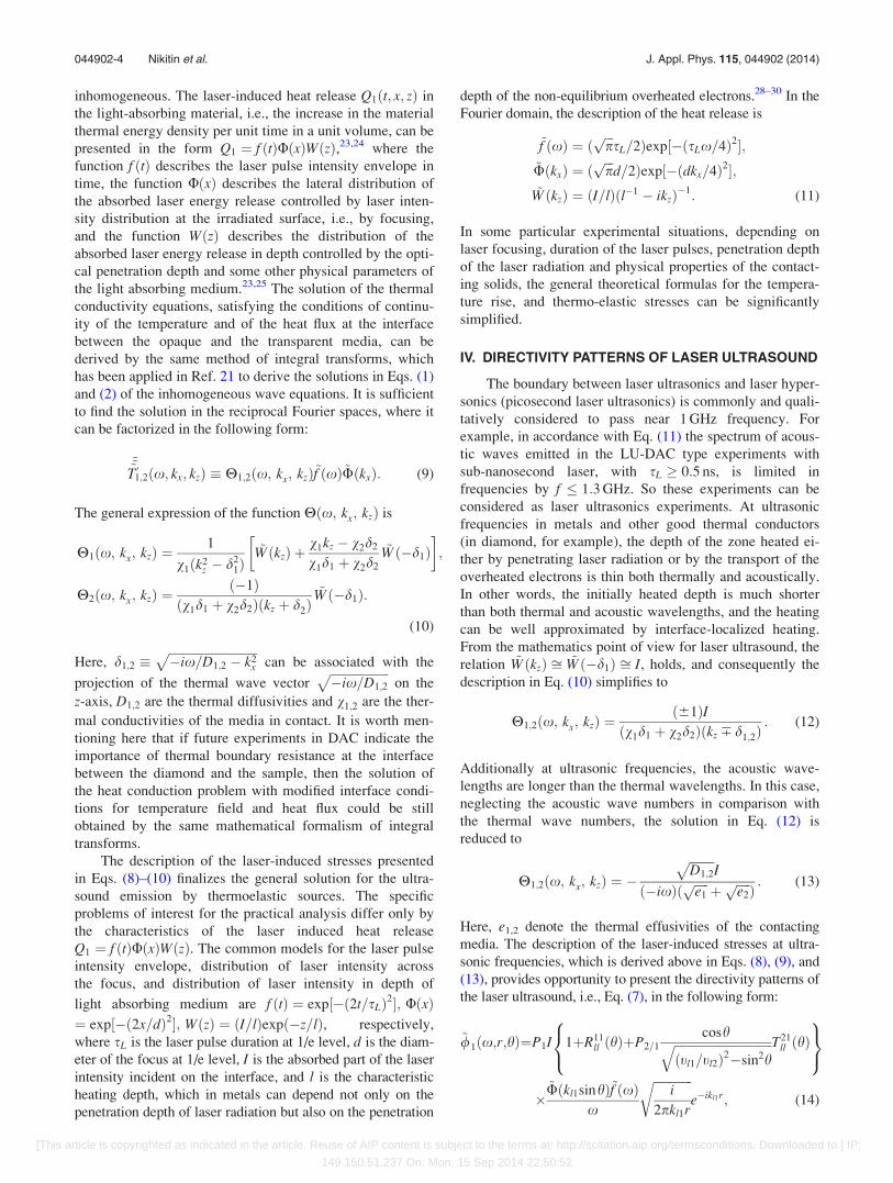
In Fig. 2, we present the results for longitudinal waves
emitted in iron (medium (1)) from its laser-irradiated inter-
face with diamond. The materials parameters used in the
evaluation are listed in Table I. The estimated critical angles
are listed in Table II. We present in Fig. 2 and in some of the
following figures the dependencies on the angle of observa-
tion both of the amplitudes and of the phases of the emitted
potentials. The knowledge of phase directivity patterns is im-
portant for the understanding of some features of the ampli-
tude directivity patterns and is necessary for the evaluation
of the emitted acoustic pulse profiles (Sec. VI).
The results presented in the middle column in Fig. 2
demonstrate the contribution to the total longitudinal laser
ultrasound signal in Fe (Eq. (16)) which is due to the
compression/dilatation waves initially generated in Fe. At
angles smaller than all the critical ones, all five acoustic
waves coupled by the interface, i.e., the incident on the inter-
face longitudinal wave and four acoustic waves created by
the interface, are all propagating, and the latter four transport
the acoustic energy from the interface to the bulk of contact-
ing media. The first characteristic feature in the directivity
patterns of both amplitudes and phases appears at critical
angle hl1=l2 ¼ arcsinðtl1=tl2Þ � 19:1 . At angles larger than
hl1=l2, the longitudinal acoustic waves in diamond are evan-
escent and they stop to transport acoustic energy away from
the interface. The second characteristic feature in the direc-
tivity patterns of both amplitudes and phases appears at
critical angle hl1=t2 ¼ arcsinðtl1=tt2Þ � 27:0 . At angles
larger than hl1=t2, the shear acoustic waves in diamond are
evanescent and they stop to transport acoustic energy away
from the interface. Thus, at angles larger than hl1=t2, the inci-
dent from Fe on the interface acoustic energy does not
induce the emission of the acoustic energy flux into diamond
(medium (2)). From the physics point of view, it would be
reasonable to expect that, under these conditions, the emis-
sion of acoustic waves in Fe would increase with angle
increasing above hl1=t2. At the same time, the emission of the
longitudinal waves in Fe should stop at angles above
hl1=l1 ¼ arcsinðtl1=tl1Þ ¼ 90:0 , when they become evanes-
cent. So the position of the second maximum in the ampli-
tude directivity pattern, which in the middle column of
Fig. 2 is between hl1=t2 and 90.0 , looks reasonable. It is
worth noting that the directivities presented in the middle
column of Fig. 2 are very different from the expected
FIG. 2. Amplitude and phase directivity
patterns of longitudinal ultrasound
emitted in iron by delta-localized sour-
ces, created by laser-irradiation of plane
interface between iron and diamond.
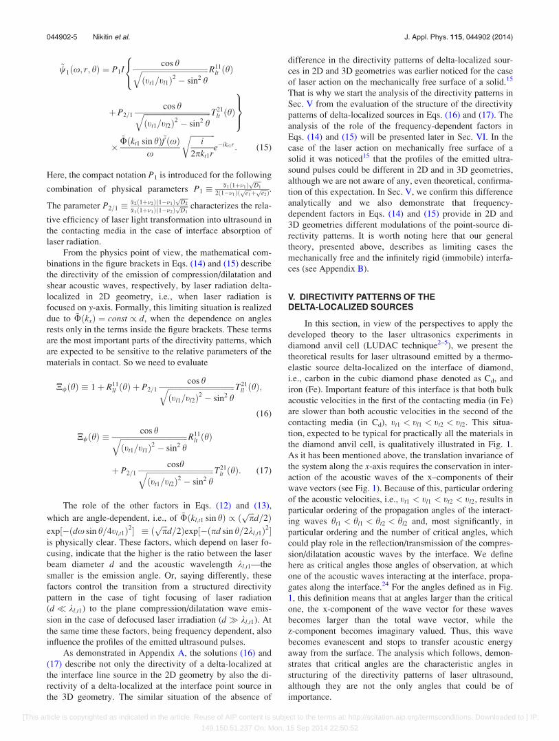
TABLE I. Values of physical parameters of diamond, iron and aluminum,
applied in the manuscript for the estimates and the evaluation of the directiv-
ity patterns.
Physical properties Diamond Iron Aluminum
Longitudinal velocity
of sound (m s�1)
18 000 5900 6420
Transverse velocity
of sound (m s�1)
13 000 3200 3040
Density (kg m�3) 3500 7900 2700
Linear thermal expansion
coefficient (K�1)
1.1� 10�6 11.3� 10�6 23.1� 10�6
Poisson’s ratio 0.20 0.30 0.34
Thermal diffusivities (m2 s�1) 7.80� 10�4 0.23� 10�4 0.84� 10�4
P2/1 � 0.46 0.07
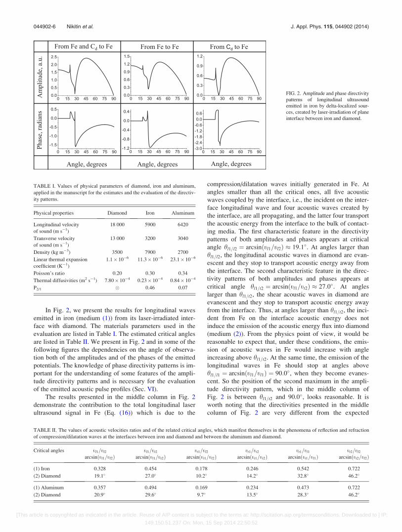
TABLE II. The values of acoustic velocities ratios and of the related critical angles, which manifest themselves in the phenomena of reflection and refraction
of compression/dilatation waves at the interfaces between iron and diamond and between the aluminum and diamond.
Critical angles tl1=tl2 tl1=tt2 tt1=tl2 tt1=tt2 tt1=tl1 tt2=tl2
arcsinðtl1=tl2Þ arcsinðtl1=tt2Þ arcsinðtt1=tl2Þ arcsinðtt1=tt2Þ arcsinðtt1=tl1Þ arcsinðtt2=tl2Þ
(1) Iron 0.328 0.454 0.178 0.246 0.542 0.722
(2) Diamond 19.1 27.0 10.2 14.2 32.8 46.2
(1) Aluminum 0.357 0.494 0.169 0.234 0.473 0.722
(2) Diamond 20.9 29.6 9.7 13.5 28.3 46.2
044902-6 Nikitin et al. J. Appl. Phys. 115, 044902 (2014)
[This article is copyrighted as indicated in the article. Reuse of AIP content is subject to the terms at: http://scitation.aip.org/termsconditions. Downloaded to ] IP:
149.150.51.237 On: Mon, 15 Sep 2014 22:50:52
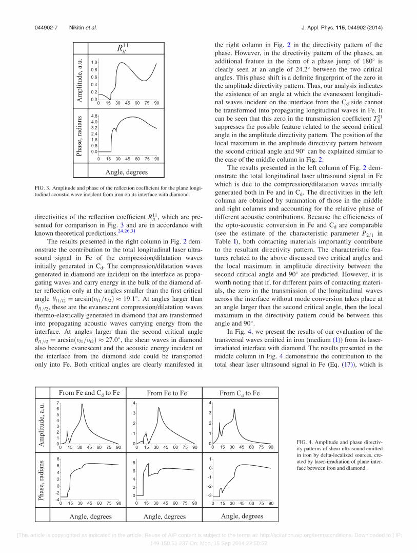
directivities of the reflection coefficient R11ll , which are pre-
sented for comparison in Fig. 3 and are in accordance with
known theoretical predictions.24,26,31
The results presented in the right column in Fig. 2 dem-
onstrate the contribution to the total longitudinal laser ultra-
sound signal in Fe of the compression/dilatation waves
initially generated in Cd. The compression/dilatation waves
generated in diamond are incident on the interface as propa-
gating waves and carry energy in the bulk of the diamond af-
ter reflection only at the angles smaller than the first critical
angle hl1=l2 ¼ arcsinðtl1=tl2Þ � 19:1 . At angles larger than
hl1=l2, these are the evanescent compression/dilatation waves
thermo-elastically generated in diamond that are transformed
into propagating acoustic waves carrying energy from the
interface. At angles larger than the second critical angle
hl1=t2 ¼ arcsinðtl1=tt2Þ � 27:0 , the shear waves in diamond
also become evanescent and the acoustic energy incident on
the interface from the diamond side could be transported
only into Fe. Both critical angles are clearly manifested in
the right column in Fig. 2 in the directivity pattern of the
phase. However, in the directivity pattern of the phases, an
additional feature in the form of a phase jump of 180 is
clearly seen at an angle of 24.2 between the two critical
angles. This phase shift is a definite fingerprint of the zero in
the amplitude directivity pattern. Thus, our analysis indicates
the existence of an angle at which the evanescent longitudi-
nal waves incident on the interface from the Cd side cannot
be transformed into propagating longitudinal waves in Fe. It
can be seen that this zero in the transmission coefficient T21ll
suppresses the possible feature related to the second critical
angle in the amplitude directivity pattern. The position of the
local maximum in the amplitude directivity pattern between
the second critical angle and 90 can be explained similar to
the case of the middle column in Fig. 2.
The results presented in the left column of Fig. 2 dem-
onstrate the total longitudinal laser ultrasound signal in Fe
which is due to the compression/dilatation waves initially
generated both in Fe and in Cd. The directivities in the left
column are obtained by summation of those in the middle
and right columns and accounting for the relative phase of
different acoustic contributions. Because the efficiencies of
the opto-acoustic conversion in Fe and Cd are comparable
(see the estimate of the characteristic parameter P2=1 in
Table I), both contacting materials importantly contribute
to the resultant directivity pattern. The characteristic fea-
tures related to the above discussed two critical angles and
the local maximum in amplitude directivity between the
second critical angle and 90 are predicted. However, it is
worth noting that if, for different pairs of contacting materi-
als, the zero in the transmission of the longitudinal waves
across the interface without mode conversion takes place at
an angle larger than the second critical angle, then the local
maximum in the directivity pattern could be between this
angle and 90 .In Fig. 4, we present the results of our evaluation of the
transversal waves emitted in iron (medium (1)) from its laser-
irradiated interface with diamond. The results presented in the
middle column in Fig. 4 demonstrate the contribution to the
total shear laser ultrasound signal in Fe (Eq. (17)), which is
FIG. 3. Amplitude and phase of the reflection coefficient for the plane longi-
tudinal acoustic wave incident from iron on its interface with diamond.
FIG. 4. Amplitude and phase directiv-
ity patterns of shear ultrasound emitted
in iron by delta-localized sources, cre-
ated by laser-irradiation of plane inter-
face between iron and diamond.
044902-7 Nikitin et al. J. Appl. Phys. 115, 044902 (2014)
[This article is copyrighted as indicated in the article. Reuse of AIP content is subject to the terms at: http://scitation.aip.org/termsconditions. Downloaded to ] IP:
149.150.51.237 On: Mon, 15 Sep 2014 22:50:52
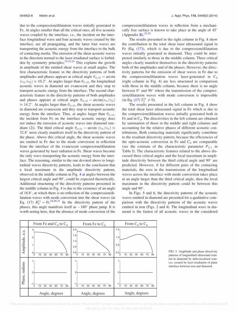
due to the compression/dilatation waves initially generated in
Fe. At angles smaller than all the critical ones, all five acoustic
waves coupled by the interface, i.e., the incident on the inter-
face longitudinal wave and four acoustic waves created by the
interface, are all propagating, and the latter four waves are
transporting the acoustic energy from the interface to the bulk
of contacting media. The emission of the shear acoustic waves
in the direction normal to the laser-irradiated surface is forbid-
den by symmetry principles.25,32,33 This explains the growth
in amplitude of the emitted shear waves at small angles. The
first characteristic feature in the directivity patterns of both
amplitudes and phases appears at critical angle ht1=l2 ¼ arcsin
ðtt1=tl2Þ � 10:2 . At angles larger than ht1=l2, the longitudinal
acoustic waves in diamond are evanescent and they stop to
transport acoustic energy from the interface. The second char-
acteristic feature in the directivity patterns of both amplitudes
and phases appears at critical angle ht1=t2 ¼ arcsinðtt1=tt2Þ� 14:2 . At angles larger than ht1=t2, the shear acoustic waves
in diamond are evanescent and they stop to transport acoustic
energy from the interface. Thus, at angles larger than ht1=t2,
the incident from Fe on the interface acoustic energy does
not induce the emission of acoustic waves into diamond (me-
dium (2)). The third critical angle ht1=l1 ¼ arcsin ðtt1=tl1Þ �32:8 most clearly manifests itself in the directivity pattern of
the phase. Above this critical angle, the shear acoustic waves
are emitted in Fe due to the mode conversion in reflection
from the interface of the evanescent compression/dilatation
waves generated by laser radiation in Fe. Shear waves become
the only wave transporting the acoustic energy from the inter-
face. The reasoning, similar to the one devoted above to longi-
tudinal waves directivity patterns, leads to the conclusion that
a local maximum in the amplitude directivity pattern,
observed in the middle column in Fig. 4 at angles between the
largest critical angle and 90 , could be expected theoretically.
Additional structuring of the directivity patterns presented in
the middle column in Fig. 4 is due to the existence of an angle
of 18.8 , at which there is no reflection of the compression/di-
latation waves with mode conversion into the shear waves (in
Eq. (17) R11lt ¼ 0).24,26,31 In the directivity pattern of the
phases, this angle manifests itself as �180 phase jump. It is
worth noting here, that the absence of mode conversion of the
compression/dilatation waves in reflection from a mechani-
cally free surface is known to take place at the angle of 45
(Appendix B).22,25
The results presented in the right column in Fig. 4 show
the contribution to the total shear laser ultrasound signal in
Fe (Eq. (17)), which is due to the compression/dilatation
waves initially generated in diamond. They could be inter-
preted similarly to those in the middle column. Three critical
angles clearly manifest themselves in the directivity patterns
both of the amplitudes and of the phases. However, the direc-
tivity patterns for the emission of shear waves in Fe due to
the compression/dilatation waves laser-generated in Cd
(right column in Fig. 4) are less structured in comparison
with those in the middle column, because there is no angle
between 0 and 90 where the transmission of the compres-
sion/dilatation waves with mode conversion is impossible
(in Eq. (17) T21lt 6¼ 0).
The results presented in the left column in Fig. 4 show
the total shear laser ultrasound signal in Fe which is due to
the compression/dilatation waves initially generated both in
Fe and in Cd. The directivities in the left column are obtained
by summation of those in the middle and right columns and
accounting for the relative phases of different acoustic con-
tributions. Both contacting materials significantly contribute
to the resultant directivity pattern, because the efficiencies of
the opto-acoustic conversion in Fe and Cd are comparable
(see the estimate of the characteristic parameter P2=1 in
Table I). The characteristic features related to the above dis-
cussed three critical angles and the local maximum in ampli-
tude directivity between the third critical angle and 90 are
predicted. However, if for different pairs of the contacting
materials, the zero in the transmission of the longitudinal
waves across the interface with mode conversion takes place
at an angle larger than the third critical angle, then the local
maximum in the directivity pattern could be between this
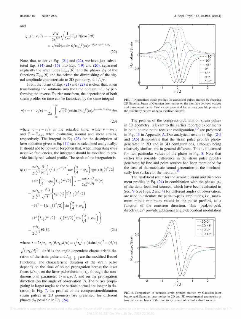
angle and 90 .In Figs. 5 and 6, the directivity patterns of the acoustic
waves emitted in diamond are presented for a qualitative com-
parison with the directivity patterns of the acoustic waves
emitted in iron (Figs. 2 and 4). The longitudinal wave in dia-
mond is the fastest of all acoustic waves in the considered
FIG. 5. Amplitude and phase directivity
patterns of longitudinal ultrasound emit-
ted in diamond by delta-localized sour-
ces, created by laser-irradiation of plane
interface between iron and diamond.
044902-8 Nikitin et al. J. Appl. Phys. 115, 044902 (2014)
[This article is copyrighted as indicated in the article. Reuse of AIP content is subject to the terms at: http://scitation.aip.org/termsconditions. Downloaded to ] IP:
149.150.51.237 On: Mon, 15 Sep 2014 22:50:52
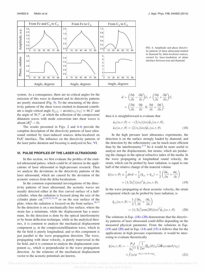
system. As a consequence, there are no critical angles for the
emission of this wave in diamond and its directivity patterns
are poorly structured (Fig. 5). To the structuring of the direc-
tivity patterns of the shear waves emitted in diamond contrib-
ute a single critical angle ht2=l2 ¼ arcsinðtt2=tl2Þ � 46:2 and
the angle of 36.7 , at which the reflection of the compression/
dilatation waves with mode conversion into shear waves is
absent (R22lt ¼ 0).
The results presented in Figs. 2 and 4–6 provide the
complete description of the directivity patterns of laser ultra-
sound emitted by laser-induced sources delta-localized on
Fe/C interface. The influence on the directivity patterns of
the laser pulse duration and focusing is analyzed in Sec. VI.
VI. PULSE PROFILES OF THE LASER ULTRASOUND
In this section, we first evaluate the profiles of the emit-
ted ultrasound pulses, which could be of interest in the appli-
cations of laser ultrasound to high-pressure research. Then
we analyze the deviations in the directivity patterns of the
laser ultrasound, which are caused by the deviation of the
acoustic sources from the delta-localization.
In the common experimental investigations of the direc-
tivity patterns of laser ultrasound, the acoustic waves are
usually detected either at the free curved surface of a half-
cylinder, when the radiation is focused along the axis of the
cylinder plane cut,8,10,12,15,18 or on the rear surface of the
plate, when the radiation is focused on the front surface.16,17
So the detection is on a mechanically free surface, where the
strain has a minimum, while the displacement has a maxi-
mum. So the detection is done by the optical interferometry
or by beam deflection technique, while in the analytical theo-
ries, it is common to analyze the mechanical displacement
component uL in the compression/dilatation wave, which in
the far field is purely longitudinal, and so this component is
just parallel to the wave propagation direction. The wave,
propagating with shear velocity, is purely transversal in the
far field, and it is common to analyze the displacement com-
ponent uT , which is perpendicular to the wave propagation
direction. As the relations of the mechanical displacement
vector to the acoustic potentials are known,
~u ¼ @/@x� @w@z
� �~ex þ
@/@zþ @w@x
� �~ez
¼ @/@x� @w@z; 0;
@/@zþ @w@x
� �;
then it is straightforward to evaluate that
~uLðx; r; hÞ ¼ �ð2=tlÞðixÞ~/1ðx; r; hÞ;~uTðx; r; hÞ ¼ ð2=ttÞðixÞ~w1ðx; r; hÞ: (18)
In the high pressure laser ultrasonics experiments, the
detection is on the surface strongly loaded by diamond, and
the detection by the reflectometry can be much more efficient
than by the interferometry.2–5 So it would be more useful to
analyze not the displacements, but strains, which are produc-
ing the changes in the optical refractive index of the media. In
the wave propagating at longitudinal sound velocity, the
strain, which can be probed by laser radiation, is equal to one
half of the relative change of the material volume
~gðx; r; hÞ � 1
2div~u ¼ 1
2ð~gxx þ ~gzzÞ ¼
1
2
@~ux
@xþ @~uz
@z
� �
¼ ð1=2t2l ÞðixÞ
2 ~u1ðx; r; hÞ: (19)
In the wave propagating at shear acoustic velocity, the strain
component which can be probed by laser radiation, is
~gxzðx; r; hÞ ¼1
2
@~ux
@zþ @~uz
@x
� �
¼ ð1=2t2t Þcosð2hÞðixÞ2 ~w1ðx; r; hÞ: (20)
The solutions in Eqs. (18)–(20) demonstrate that the directiv-
ity patterns of laser ultrasound could differ depending on the
measured physical parameter. From the solutions in Eqs.
(19) and (20) and in Eqs. (14) and (15) it follows that for the
applications in high pressure experiments, it would be inter-
esting to evaluate theoretically
~gðx; r; hÞ ¼ � P1I
2t3=2l
ffiffiffiffiffiffiffiffi1
2pr
rjN/ðhÞj
ffiffiffiffixp
~Uðx sin h=tl1Þ
� ~f ðxÞe�ikl1rþip=4þiuN ; (21)
FIG. 6. Amplitude and phase directiv-
ity patterns of shear ultrasound emitted
in diamond by delta-localized sources,
created by laser-irradiation of plane
interface between iron and diamond.
044902-9 Nikitin et al. J. Appl. Phys. 115, 044902 (2014)
[This article is copyrighted as indicated in the article. Reuse of AIP content is subject to the terms at: http://scitation.aip.org/termsconditions. Downloaded to ] IP:
149.150.51.237 On: Mon, 15 Sep 2014 22:50:52
and
~gxzðx; r; hÞ ¼ �P1I
2t3=2t
ffiffiffiffiffiffiffiffi1
2pr
rjNwðhÞjcosð2hÞ
�ffiffiffiffixp
~Uðx sin h=tt1Þ~f ðxÞe�ikl1rþip=4þiuN :
(22)
Note, that, to derive Eqs. (21) and (22), we have just substi-
tuted Eqs. (14) and (15) into Eqs. (19) and (20), separated
explicitly the amplitudes jNu;wðhÞj and the phases /N of the
functions Nu;wðhÞ and factorized the diminishing of the sig-
nal amplitude characteristic to 2D geometry, / 1=ffiffirp
.
From the forms of Eqs. (21) and (22) it is clear that, when
transforming the solutions into the time domain, i.e., by per-
forming the inverse Fourier transform, the dependence of both
strain profiles on time can be factorized by the same integral
gðs¼ t� r=tÞ ¼ 1
2p
ðþ1�1
ffiffiffiffixp
~Uðx sinh=tÞ~f ðxÞeixsþip=4þiuNdx;
(23)
where s ¼ t� r=t is the retarded time, while t ¼ tl1;t1
and N ¼ N/;w, when evaluating normal and shear strains,
respectively. The integral in Eq. (23) for the description of
laser radiation given in Eq. (11) can be calculated analytically.
It should not be however forgotten that, when integrating over
negative frequencies, the integrand should be modified to pro-
vide finally real valued profile. The result of the integration is
gðsÞ ¼ pdsL
2s3=2a
@
@�s
ffiffiffiffiffij�sj
pe��s2=2 cos
p4þ uN
� �sgnðsÞI1
4�s2=2� ��
þsinp4þ uN
� �I�1
4�s2=2� ��
� pdsL
2s3=2a
@
@�sWð�sÞ
¼ pdsL
2s3=2a
e��s2=2ffiffiffiffiffij�sj
p(
sgnðsÞ �s2I�54
�s2=2� �h
�ð�s2 � 1ÞI�14
�s2=2� �i
sinp4þ uN
� �
þ�s2 I�34
�s2=2� �
� I14
�s2=2� �� �
cosp4þ uN
� �)
� pdsL
2s3=2a
Hð�sÞ; (24)
where �s�2s=sa, saðh;sL;d=tÞ¼ffiffiffiffiffiffiffiffiffiffiffiffiffiffiffiffiffiffiffiffiffiffiffiffiffiffiffiffiffiffiffiffiffisL
2þðdsinh=tÞ2q
�ðd=tÞffiffiffiffiffiffiffiffiffiffiffiffiffiffiffiffiffiffiffiffiffiffiffiffiffiffiffiffiffiffiffiffiðtsL=dÞ2þsin2h
qis the angle-dependent characteristic du-
ration of the strain pulse and I614;�3
4;�5
4are the modified Bessel
functions. The characteristic duration of the strain pulse
depends on the time of sound propagation across the laser
focus ðd=tÞ, on the laser pulse duration sL, through the non-
dimensional parameter �sL� sLt=d, and on the propagation
direction (on the angle of observation h). The pulses propa-
gating at larger angles to the surface normal are longer in du-
ration. In Fig. 7, the profiles of the compression/dilatation
strain pulses in 2D geometry are presented for different
phases /N possible in Eq. (24).
The profiles of the compression/dilatation strain pulses
in 3D geometry, relevant to the earlier reported experiments
in point-source-point-receiver configuration,2,3 are presented
in Fig. 13 in Appendix A. Our analytical results in Eqs. (24)
and (A5) demonstrate that the strain pulse profiles photo-
generated in 2D and in 3D configurations, although being
relatively similar, are in general different. This is illustrated
for two particular values of the phase in Fig. 8. Note that
earlier this possible difference in the strain pulse profiles
generated by line and point sources had been mentioned for
the case of thermoelastic sound generation at the mechani-
cally free surface of the medium.15
The analytical result for the acoustic strain and displace-
ment profiles in Eq. (24) in combination with the phases uNof the delta-localized sources, which have been evaluated in
Sec. V (see Figs. 2 and 4) for different angles of observation,
are used to calculate the peak-to-peak amplitudes, i.e., maxi-
mum minus minimum values in the pulse profiles, as a
function of the emission direction. This “peak-to-peak
directivities” provide additional angle-dependent modulation
FIG. 7. Normalized strain profiles for acoustical pulses emitted by focusing
2D Gaussian beam of Gaussian laser pulses on the interface between opaque
and transparent media. Profiles are presented for various possible phases of
the directivity pattern of delta-localized sources.
FIG. 8. Comparison of acoustic strain profiles emitted by Gaussian laser
beams and Gaussian laser pulses in 2D and 3D experimental geometries at
two particular phases of the directivity pattern of delta-localized sources.
044902-10 Nikitin et al. J. Appl. Phys. 115, 044902 (2014)
[This article is copyrighted as indicated in the article. Reuse of AIP content is subject to the terms at: http://scitation.aip.org/termsconditions. Downloaded to ] IP:
149.150.51.237 On: Mon, 15 Sep 2014 22:50:52
of the directivities patterns evaluated for the delta-localized
sources in Sec. V (see Figs. 2 and 4). It should be also taken
into account that in comparison with the solutions for the
particle displacements in Eq. (18) and the solution for the
compression/dilatation strain in Eqs. (19) and (21), the solu-
tion for the shear strain in Eqs. (20) and (22) contains an
extra angle-dependent factor cosð2hÞ. The evaluated angle-
dependent functions, providing modulation of the directivity
patterns of laser ultrasound, emitted by delta-localized sour-
ces and described by the amplitudes of the solutions in Eqs.
(16) and (17), are presented for the 2D case in Fig. 9. They
are evaluated for the following values of the parameters,
sL ¼ 0:5 ns, d ¼ 5 lm, and tl ¼ 5900 m/s, tt ¼ 3200 m/s,
�sL;l � sLtl=d ¼ 0:59, �sL;t � sLtt=d ¼ 0:32, which are char-
acteristic to the earlier reported LU-DAC experiments in
line-source-point-receiver configuration with Fe.4,5 The
modulation functions for the 3D case are presented in Fig.
14 of Appendix A. It can be concluded that a part of the zero
in modulation function of the shear strain, which is a formal
effect related to the definition of the shear strain in Eq. (20),
the modulation functions in Fig. 9 are smooth and do not pro-
vide additional qualitative structuring of the directivity pat-
terns. However this conclusion, based on the analysis of
Fig. 9, is valid only because the characteristic non-
dimensional parameter, i.e., �sL;l ¼ 0:59, is rather close to 1.
The dependence of the modulation functions on angle could
be much more important if the characteristic non-dimensional
parameter �sL � tsL=d is significantly smaller than 1, while,
when �sL � 1, the dependence of the strain pulse amplitude
on the angle is negligible.
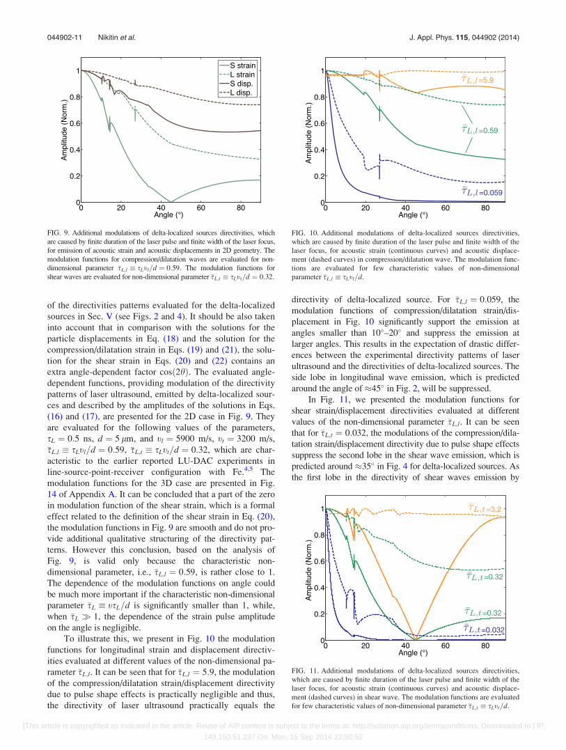
To illustrate this, we present in Fig. 10 the modulation
functions for longitudinal strain and displacement directiv-
ities evaluated at different values of the non-dimensional pa-
rameter �sL;l. It can be seen that for �sL;l ¼ 5:9, the modulation
of the compression/dilatation strain/displacement directivity
due to pulse shape effects is practically negligible and thus,
the directivity of laser ultrasound practically equals the
directivity of delta-localized source. For �sL;l ¼ 0:059, the
modulation functions of compression/dilatation strain/dis-
placement in Fig. 10 significantly support the emission at
angles smaller than 10 –20 and suppress the emission at
larger angles. This results in the expectation of drastic differ-
ences between the experimental directivity patterns of laser
ultrasound and the directivities of delta-localized sources. The
side lobe in longitudinal wave emission, which is predicted
around the angle of �45 in Fig. 2, will be suppressed.
In Fig. 11, we presented the modulation functions for
shear strain/displacement directivities evaluated at different
values of the non-dimensional parameter �sL;l. It can be seen
that for �sL;t ¼ 0:032, the modulations of the compression/dila-
tation strain/displacement directivity due to pulse shape effects
suppress the second lobe in the shear wave emission, which is
predicted around �35 in Fig. 4 for delta-localized sources. As
the first lobe in the directivity of shear waves emission by
FIG. 9. Additional modulations of delta-localized sources directivities, which
are caused by finite duration of the laser pulse and finite width of the laser focus,
for emission of acoustic strain and acoustic displacements in 2D geometry. The
modulation functions for compression/dilatation waves are evaluated for non-
dimensional parameter �sL;l � sLtl=d ¼ 0:59. The modulation functions for
shear waves are evaluated for non-dimensional parameter �sL;t � sLtt=d ¼ 0:32.
FIG. 10. Additional modulations of delta-localized sources directivities,
which are caused by finite duration of the laser pulse and finite width of the
laser focus, for acoustic strain (continuous curves) and acoustic displace-
ment (dashed curves) in compression/dilatation wave. The modulation func-
tions are evaluated for few characteristic values of non-dimensional
parameter �sL;l � sLtl=d.
FIG. 11. Additional modulations of delta-localized sources directivities,
which are caused by finite duration of the laser pulse and finite width of the
laser focus, for acoustic strain (continuous curves) and acoustic displace-
ment (dashed curves) in shear wave. The modulation functions are evaluated
for few characteristic values of non-dimensional parameter �sL;t � sLtt=d.
044902-11 Nikitin et al. J. Appl. Phys. 115, 044902 (2014)
[This article is copyrighted as indicated in the article. Reuse of AIP content is subject to the terms at: http://scitation.aip.org/termsconditions. Downloaded to ] IP:
149.150.51.237 On: Mon, 15 Sep 2014 22:50:52

delta-localized sources is also expected at non-zero angle from
symmetry considerations (see Sec. V) and is around �10
angle in Fig. 4, then the pulse shape related modulation func-
tion significantly suppresses this first shear lobe as well.
From the physics point of view, these theoretical predic-
tions correspond to the transition, with diminishing parameter
�sL, from delta-localized sources to plane sources, accompa-
nied by preferential photo-generation of plane compression/
dilatation waves propagating normally to the laser-irradiated
surface, and to suppression of shear waves photo-generation.
The above developed theory provides opportunity to evaluate
the directivity patterns of LU for any intermediate situations
between the emission of strongly divergent acoustic fields and
the emission of the acoustic beams, which are quasi-collinear
with the normal to the interface.
VII. DISCUSSION
The interpretations of the multiple lobes in the ampli-
tude directivity patterns had been proposed in Sec. V on the
basis of the evaluation of the critical angles and the possible
angles for the absence in reflection/transmission of the acous-
tic waves across the interface. These interpretations indicate
that the theoretically predicted in Figs. 2 and 4 directivities of
the delta-localized thermo-elastic stresses can be understood
qualitatively from the physics point of view. In addition,
we demonstrate in Appendix B that the developed theory
perfectly reproduces the well-known results12,14,15 for the di-
rectivity patterns of the laser ultrasound emitted from the
laser-irradiated mechanically free surface of the media.
In the absence of the available experimental measure-
ments for comparison, we have compared the predictions of
our analytical theory with the recently published results of
the numerical evaluation of the directivities patterns in dia-
mond anvil cell by the finite element method.19 Because in
Ref. 19 the interface between the aluminum (Al) and the dia-
mond is considered, we have applied our theory to this com-
bination of the materials. The directivity patterns for the
delta-localized sources, presented in Fig. 12, are evaluated
for the similar material parameters as in Ref. 19. They
should be compared with the directivity patterns presented in
Figs. 5(c) and 5(d) in Ref. 19. By comparing the results in
Fig. 12 with those in Figs. 2 and 4, it can be concluded that
the main theoretical predictions for the interface Al/Cd and
the interface Fe/Cd are qualitatively similar, as it could have
been expected from the absence of important difference
between Al and Fe in values of acoustic velocities, Poisson
ratios and critical angles on the interface with diamond (see
Tables I and II), and consist in the description of structuring
of the directivity patterns. The analytical theory predicts sev-
eral lobes in the directivity patterns both for the longitudinal
and shear waves. These analytical predictions are not sup-
ported by the results of the numerical evaluations presented
in Figs. 5(c) and 5(d) of Ref. 19, where both directivity pat-
terns are poorly structured. In particular, numerical investi-
gation19 does not predict the dominant lobe in the directivity
pattern of the longitudinal waves around �45 , which is ana-
lytically predicted in Fig. 12. It should be mentioned here
that we have evaluated the pulse-shape effects, predicted in
Sec. VI using the same parameters of the laser radiation as
in Ref. 19, i.e., sL ¼ 0:5 ns, d ¼ 5 lm. We have found
that the additional angle-dependent modulation, i.e., due to
pulse-shape effects, cannot cut the side lobe predicted in
Fig. 12 for longitudinal waves around �45 . Thus, our ana-
lytical results are in contradiction with the numerical theory
in Ref. 19. However, we are not considering the predictions
obtained in Ref. 19 as a strong argument against our analyti-
cal theory, because some of the other numerical evaluations
in Ref. 19 are also in contradiction and not only with the
results of the analytical theory but also with the available
experimental results. In fact, the numerically evaluated direc-
tivity patterns for the emission of the shear acoustic waves
from the laser-irradiated mechanically free surface, presented
in Fig. 5(b) of Ref. 19, do not contain the second side lobe at
large angles exceeding 60 (see Fig. 15 of Appendix B),
which is not only well-established by analytical theories12,14,15
but has been recently observed experimentally.18
Finally, one more, although indirect, argument in favor of
validity of the theory, developed by us in this manuscript, is the
known theoretical prediction34 for the modification of the direc-
tivity pattern of the laser ultrasound emitted in liquid in case,
when the surface of the liquid is loaded by a solid plate.
Additional structuring of the directivity pattern, relative to the
pattern of laser ultrasound emitted from a mechanically free sur-
face of laser-irradiated liquid, had been predicted.34 Several
lobes in the directivity pattern are theoretically expected.34
VIII. CONCLUSIONS
We presented the analytical descriptions for the directiv-
ity patterns of ultrasound (LU), emitted from the laser-
irradiated interface between two isotropic solids. The
solutions are valid for arbitrary combinations of transparent
and opaque materials. The directivity patterns are derived by
accounting for the specific features of the sound generation
by the thermo-elastic stresses distributed in the volume,
which are essential for laser ultrasonics. We also presented
FIG. 12. Amplitude directivity patterns of longitudinal and shear ultrasound
emitted in aluminum by delta-localized sources, created by laser-irradiation
of plane interface between aluminum and diamond.
044902-12 Nikitin et al. J. Appl. Phys. 115, 044902 (2014)
[This article is copyrighted as indicated in the article. Reuse of AIP content is subject to the terms at: http://scitation.aip.org/termsconditions. Downloaded to ] IP:
149.150.51.237 On: Mon, 15 Sep 2014 22:50:52
the analytical solutions for the profiles of longitudinal and
shear acoustic pulses emitted in different directions. The
derived mathematical formulas provide straight opportunity
to predict the acoustic field, which is formed in the DAC af-
ter photo-generation and several reflections of bulk acoustic
waves at the interfaces. The developed theory can be
applied in the future for the dimensional scaling the LU-
DAC experiments, optimization of these experiments (in
terms of a choice of the optimal directions/positions for
acoustic waves detection) and the interpretation of the ex-
perimental results.
ACKNOWLEDGMENTS
This research was conducted in the frame of the project
“LUDACISM” supported by the program ANR BLANC
2011.
APPENDIX A: DIRECTIVITY PATTERNS IN THE 3D CASE
The solution for the directivity pattern in the point-
source configuration can be derived by an approach which
is similar to the one shown in the main text for the 2D case.
The spatial Fourier transform along the x-axis in 2D is
replaced in the case of 3D and cylindrical symmetry by the
Hankel (Fourier-Bessel) transform along the transverse ra-
dial coordinate r? in the (x,y) plane. The only modification
in the solutions for the acoustic potentials and the tempera-
ture field in the reciprocal spaces is the replacement of kx
by k?, which is the projection of the wave-vectors on the
(x,y) plane. Equation (5) is replaced by the inverse Hankel
transform over k?, which can be calculated by the method
of steepest descent.26,27 This results in the following form
of Eq. (6) in the 3D case
~/1ðx; r; hÞ~w1ðx; r; hÞ
0@
1A ¼ cosh
kl1~~/1ðx; kl1 sin hÞ
kt1~~w1ðx; kt1 sin hÞ
0B@
1CA
� i
r
e�ikl1r
e�ikt1r
0@
1A: (A1)
So just the multiplier,ffiffiffiffiffiffiffiffiffiikl;t1
q=ð2prÞ, characteristic to
2D geometry, is replaced in 3D cylindrical geometry by
ikl;t1=r. This provides correct diminishing of the acoustic
wave amplitude with distance from the source, / 1=r,
and modifies the profiles of the emitted acoustic pulses.
The description of the normal strain in Eq. (21) is modified
into
~gðx;r;hÞ¼�P1I
2t2l
1
rjN/ðhÞjx~Uðxsinh=tl1Þ~f ðxÞe�ikl1rþip=2þiuN ;
(A2)
and the description of the shear strain in Eq. (22) is modified
into
~gr?zðx; r; hÞ ¼1
2
@~ur?
@zþ @~uz
@r?
� �
¼ �P1I
2t2t
1
rjNwðhÞjcosð2hÞx~Uðx sin h=tt1Þ~f ðxÞ
� e�ikl1rþip=2þiuN : (A3)
The dependence of both strain profiles on time can be factor-
ized by the same integral
gðs ¼ t� r=tÞ ¼ 1
2p
ðþ1�1
x~Uðx sin h=tÞ~f ðxÞeixsþip=2þiuNdx:
(A4)
The integral in Eq. (A4), in case, where the description of
laser radiation is given in Eq. (11), can be calculated analyti-
cally. It should not be forgotten, however, that, when inte-
grating over negative frequencies, the integrand should be
modified to provide finally real valued profile. The result of
the integration is
gðsÞ¼ffiffiffipp
dsL
s2a
@
@�se��s2
cosuNþ ierf i�sð ÞsinuN
�n o
�ffiffiffipp
dsL
s2a
@
@�sWð�sÞ
¼ffiffiffipp
dsL
s2a
� 2ffiffiffipp sinuN�2�se��s2
cosuN�erfið�sÞsinuN½ �
�ffiffiffipp
dsL
s2a
Hð�sÞ; (A5)
where all the notations are the same as in the 2D case analyzed
in Sec. VI and erf is the error function (probability integral).
The evaluated (with the use of Eq. (A5)) profiles of the com-
pression/dilatation strain pulses in 3D geometry, relevant to
the earlier reported experiments in point-source-point-receiver
configuration,2,3 are presented in Fig. 13. The angle-dependent
functions, providing modulation of the directivity patterns of
laser ultrasound, emitted by delta-localized sources and
described by the amplitudes of the solutions in Eqs. (16) and
(17), are presented for the 3D case in Fig. 14. They are eval-
uated for the same parameters of material and laser pulses as
in the 2D case in Sec. VI.
APPENDIX B: DIRECTIVITY PATTERNS OF LASERULTRASOUND EMITTED FROM MECHANICALLY FREEAND RIGID INTERFACES
The directivity patterns of laser ultrasound emitted due
to laser-irradiation of the mechanically free surface of iron,
which are computed as an asymptotic case of the general for-
mulas in Eqs. (16) and (17), are presented in Fig. 15.
On the one hand, the comparison of Fig. 15 with the
well-documented results existing in the literature for
the mechanically free surface,12,14,15 confirms the validity of
our analytical theory in this limiting case. On the other hand,
the results presented in the right column in Fig. 15 clearly
044902-13 Nikitin et al. J. Appl. Phys. 115, 044902 (2014)
[This article is copyrighted as indicated in the article. Reuse of AIP content is subject to the terms at: http://scitation.aip.org/termsconditions. Downloaded to ] IP:
149.150.51.237 On: Mon, 15 Sep 2014 22:50:52
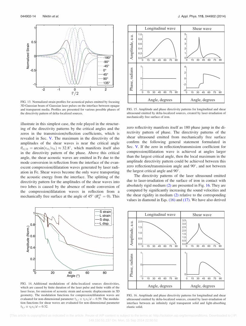
illustrate in this simplest case, the role played in the structur-
ing of the directivity patterns by the critical angles and the
zeros in the transmission/reflection coefficients, which is
revealed in Sec. V. The maximum in the directivity of the
amplitudes of the shear waves is near the critical angle
ht1=l1 ¼ arcsinðtt1=tl1Þ � 32:8 , which manifests itself also
in the directivity pattern of the phase. Above this critical
angle, the shear acoustic waves are emitted in Fe due to the
mode conversion in reflection from the interface of the evan-
escent compression/dilatation waves generated by laser radi-
ation in Fe. Shear waves become the only wave transporting
the acoustic energy from the interface. The splitting of the
directivity pattern for the amplitudes of the shear waves into
two lobes is caused by the absence of mode conversion of
the compression/dilatation waves in reflection from a
mechanically free surface at the angle of 45 (R11lt ¼ 0). This
zero reflectivity manifests itself as 180 phase jump in the di-
rectivity pattern of phase. The directivity patterns of the
shear ultrasound emitted from mechanically free surface
confirm the following general statement formulated in
Sec. V. If the zero in reflection/transmission coefficient for
compression/dilatation wave is achieved at angles larger
than the largest critical angle, then the local maximum in the
amplitude directivity pattern could be achieved between this
zero reflection/transmission angle and 90 , and not between
the largest critical angle and 90 .The directivity patterns of the laser ultrasound emitted
due to laser-irradiation of the surface of iron in contact with
absolutely rigid medium (2) are presented in Fig. 16. They are
computed by significantly increasing the sound velocities and
the shear rigidity in medium (2) relative to the corresponding
values in diamond in Eqs. (16) and (17). We have also derived
FIG. 14. Additional modulations of delta-localized sources directivities,
which are caused by finite duration of the laser pulse and finite width of the
laser focus, for emission of acoustic strain and acoustic displacements in 3D
geometry. The modulation functions for compression/dilatation waves are
evaluated for non-dimensional parameter �sL;l � sLtl=d ¼ 0:59. The modula-
tion functions for shear waves are evaluated for non-dimensional parameter
�sL;t � sLtt=d ¼ 0:32.
FIG. 15. Amplitude and phase directivity patterns for longitudinal and shear
ultrasound emitted by delta-localized sources, created by laser-irradiation of
mechanically free surface of iron.
FIG. 13. Normalized strain profiles for acoustical pulses emitted by focusing
3D Gaussian beam of Gaussian laser pulses on the interface between opaque
and transparent media. Profiles are presented for various possible phases of
the directivity pattern of delta-localized sources.
FIG. 16. Amplitude and phase directivity patterns for longitudinal and shear
ultrasound emitted by delta-localized sources, created by laser-irradiation of
interface between an infinitely rigid transparent solid and light-absorbing
elastic solid.
044902-14 Nikitin et al. J. Appl. Phys. 115, 044902 (2014)
[This article is copyrighted as indicated in the article. Reuse of AIP content is subject to the terms at: http://scitation.aip.org/termsconditions. Downloaded to ] IP:
149.150.51.237 On: Mon, 15 Sep 2014 22:50:52
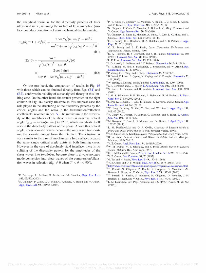
the analytical formulas for the directivity patterns of laser
ultrasound in Fe, assuming the surface of Fe is immobile (sur-
face boundary conditions of zero mechanical displacements),
N/ðhÞ � 1þ R11ll ðhÞ ¼
2 cos hffiffiffiffiffiffiffiffiffiffiffiffiffiffiffiffiffiffiffiffiffiffiffiffiffiffiffiffiffiffiffiffiffiffiffiðtl1=tt1Þ2 � sin2 h
qsin2 hþ cos h
ffiffiffiffiffiffiffiffiffiffiffiffiffiffiffiffiffiffiffiffiffiffiffiffiffiffiffiffiffiffiffiffiffiffiffiðtl1=tt1Þ2 � sin2 h
q ;
(B1)
NwðhÞ �cos hffiffiffiffiffiffiffiffiffiffiffiffiffiffiffiffiffiffiffiffiffiffiffiffiffiffiffiffiffiffiffiffiffiffiffi
ðtt1=tl1Þ2 � sin2 hq R11
lt ðhÞ
¼ 2 cos h sin h
sin2 hþ cos hffiffiffiffiffiffiffiffiffiffiffiffiffiffiffiffiffiffiffiffiffiffiffiffiffiffiffiffiffiffiffiffiffiffiffiðtt1=tl1Þ2 � sin2 h
q : (B2)
On the one hand, the comparison of results in Fig. 16
with those which can be obtained directly from Eqs. (B1) and
(B2), confirms the validity of our analytical theory in this lim-
iting case. On the other hand, the results presented in the right
column in Fig. B2 clearly illustrate in this simplest case the
role played in the structuring of the directivity patterns by the
critical angles and the zeros in the transmission/reflection
coefficients, revealed in Sec. V. The maximum in the directiv-
ity of the amplitudes of the shear waves is near the critical
angle ht1=l1 ¼ arcsinðtt1=tl1Þ � 32:8 , which manifests itself
also in the directivity pattern of the phase. Above this critical
angle, shear acoustic waves become the only wave transport-
ing the acoustic energy from the interface. The situation is
very similar to the case of mechanically free surface, because
the same single critical angle exists in both limiting cases.
However in the case of absolutely rigid interface, there is no
splitting of the directivity pattern for the amplitudes of the
shear waves into two lobes, because there is always nonzero
mode conversion into shear waves of the compression/dilata-
tion waves in reflection (R11lt 6¼ 0 when 0 < ht1 < 90 ).
1F. Decremps, L. Belliard, B. Perrin, and M. Gauthier, Phys. Rev. Lett.
100, 035502 (2008).2N. Chigarev, P. Zinin, L.-C. Ming, G. Amulele, A. Bulou, and V. Gusev,
Appl. Phys. Lett. 93, 181905 (2008).
3P. V. Zinin, N. Chigarev, D. Mounier, A. Bulou, L. C. Ming, T. Acosta,
and V. Gusev, J. Phys.: Conf. Ser. 215, 012053 (2010).4N. Chigarev, P. Zinin, D. Mounier, A. Bulou, L. C. Ming, T. Acosta, and
V. Gusev, High Pressure Res. 30, 78 (2010).5N. Chigarev, P. Zinin, D. Mounier, A. Bulou, A. Zerr, L. C. Ming, and V.
Gusev, J. Phys.: Conf. Ser. 278, 012017 (2011).6C. B. Scruby, R. J. Dewhurst, D. A. Hutchins, and S. B. Palmer, J. Appl.
Phys. 51, 6210 (1980).7C. B. Scruby and L. E. Drain, Laser Ultrasonics Techniques andApplications (Hilger, Bristol, 1990).
8D. A. Hutchins, R. J. Dewhurst, and S. B. Palmer, Ultrasonics 19, 103
(1981); J. Acoust. Soc. Am. 70, 1362 (1981).9L. F. Rose, J. Acoust. Soc. Am. 75, 723 (1984).
10J. D. Aussel, A. Le Brun, and J. C. Baboux, Ultrasonics 26, 245 (1988).11S. Y. Zhang, M. Paul, S. Fassbender, U. Schleichert, and W. Arnold, Res.
Nondestr. Eval. 2, 143 (1990).12P. Zhang, C. F. Ying, and J. Shen, Ultrasonics 35, 233 (1997).13B. Yuhai, P. Liwei, F. Qiping, Y. Yuping, and Y. Chongfu, Ultrasonics 33,
429 (1995).14W. Japing, S. Dufang, and H. Yulong, J. Appl. Phys. 83, 1207 (1998).15J. R. Bernstein and J. B. Spicer, J. Acoust. Soc. Am. 107, 1352 (2000).16S. Raetz, T. Dehoux, and B. Audoin, J. Acoust. Soc. Am. 130, 3691
(2011).17J. M. S. Sakamoto, B. R. Tittman, A. Baba, and G. M. Pacheco, J. Phys.:
Conf. Ser. 278, 012032 (2011).18C. Pei, K. Demachi, H. Zhu, T. Fukuchi, K. Koyama, and M. Uesaka, Opt.
Laser Technol. 44, 860 (2012).19W. Feng, D. Yang, X. Zhu, Y. Guo, and W. Liao, J. Appl. Phys. 111,
013107 (2012).20V. Gusev, C. Desmet, W. Lauriks, C. Glorieux, and J. Thoen, J. Acoust.
Soc. Am. 100, 1514 (1996).21M. Kouyate, T. Pezeril, D. Mounier, and V. Gusev, J. Appl. Phys. 110,
123526 (2011).22L. M. Brekhovskikh and O. A. Godin, Acoustics of Layered Media I:
Plane and Quasi-Plane Waves (Berlin, Springer-Verlag, 1990).23V. E. Gusev and A. Karabutov, Laser Optoacoustics (AIP, New York, 1993).24B. A. Auld, Acoustic Fields and Waves in Solids, 2nd ed. (Krieger,
Malabar, 1990), Vol. 2.25V. E. Gusev, Appl. Phys. Lett. 94, 164105 (2009).26W. M. Ewing, W. S. Jardetzky, and F. Press, Elastic Waves in Layered
Media (McGraw-Hill, New York, 1957).27G. F. Miller and H. Purcey, Proc. R. Soc. London, Ser. A 223, 521 (1954).28V. E. Gusev, Opt. Commun. 94, 76 (1992).29G. Tas and H. Maris, Phys. Rev. B 49, 15046 (1994).30V. E. Gusev and O. B. Wright, Phys. Rev. B 57, 2878–2888 (1998).31http://www.crewes.org/ResearchLinks/ExplorerPrograms/ZE/ZEcrewes.html.32T. Pezeril, N. Chigarev, P. Ruello, S. Gougeon, D. Mounier, J.-M.
Breteau, P. Picart, and V. Gusev, Phys. Rev. B 73, 132301 (2006).33T. Pezeril, P. Ruello, S. Gougeon, N. Chigarev, D. Mounier, J.-M.
Breteau, P. Picart, and V. Gusev, Phys. Rev. B 75, 174307 (2007).34L. M. Lyamshev, Sov. Phys. Acoustics 25, 322 (1979) [Akust. Zh. 25, 566
(1979)].
044902-15 Nikitin et al. J. Appl. Phys. 115, 044902 (2014)
[This article is copyrighted as indicated in the article. Reuse of AIP content is subject to the terms at: http://scitation.aip.org/termsconditions. Downloaded to ] IP:
149.150.51.237 On: Mon, 15 Sep 2014 22:50:52