Embed Size (px)
Citation preview
Directionally Selective Fractional WaveletTransform Using a 2-D Non-Separable
Unbalanced Lifting Structure
Furkan Keskin and A. Enis Cetin
Department of Electrical and Electronics Engineering,Bilkent University, Bilkent, 06800, Ankara, [email protected],[email protected]
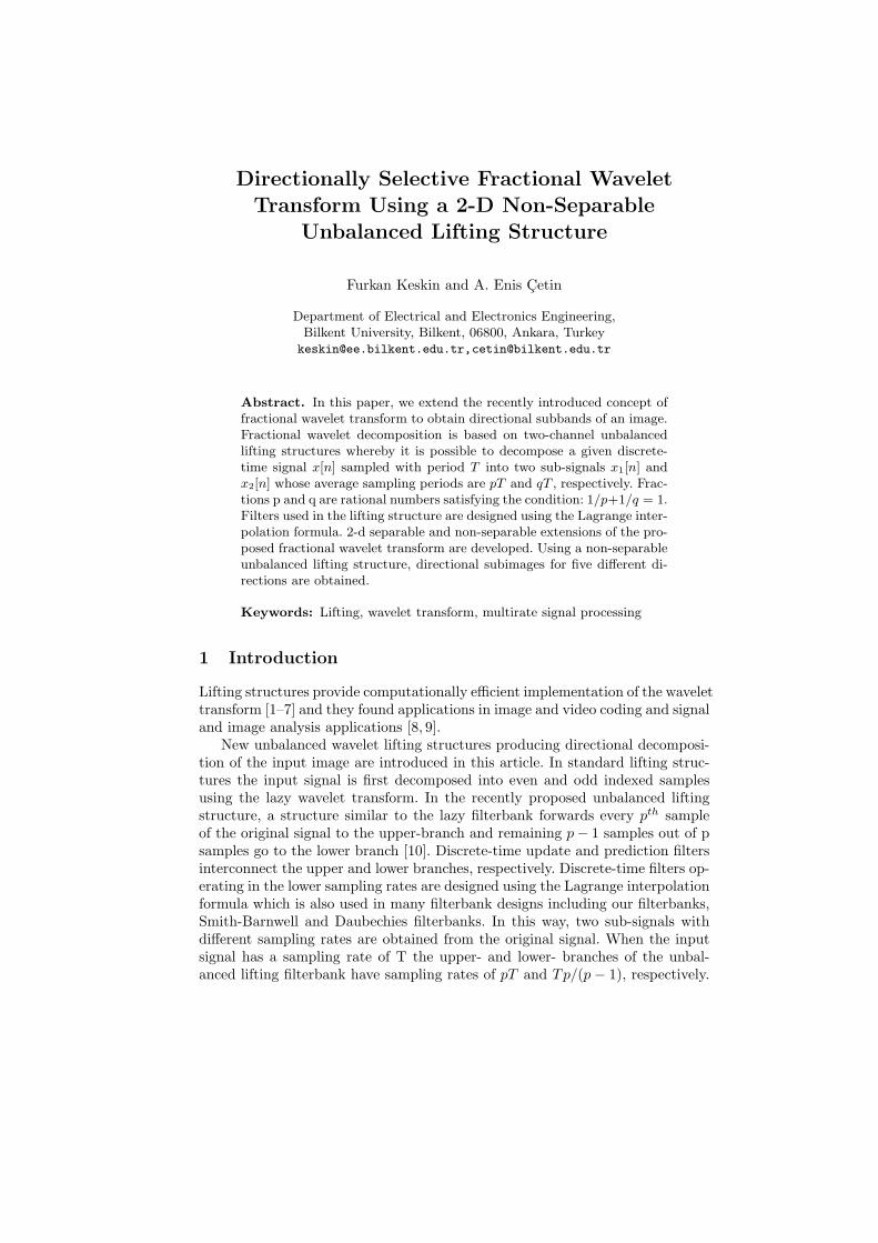
Abstract. In this paper, we extend the recently introduced concept offractional wavelet transform to obtain directional subbands of an image.Fractional wavelet decomposition is based on two-channel unbalancedlifting structures whereby it is possible to decompose a given discrete-time signal x[n] sampled with period T into two sub-signals x1[n] andx2[n] whose average sampling periods are pT and qT , respectively. Frac-tions p and q are rational numbers satisfying the condition: 1/p+1/q = 1.Filters used in the lifting structure are designed using the Lagrange inter-polation formula. 2-d separable and non-separable extensions of the pro-posed fractional wavelet transform are developed. Using a non-separableunbalanced lifting structure, directional subimages for five different di-rections are obtained.
Keywords: Lifting, wavelet transform, multirate signal processing
1 Introduction
Lifting structures provide computationally efficient implementation of the wavelettransform [1–7] and they found applications in image and video coding and signaland image analysis applications [8, 9].
New unbalanced wavelet lifting structures producing directional decomposi-tion of the input image are introduced in this article. In standard lifting struc-tures the input signal is first decomposed into even and odd indexed samplesusing the lazy wavelet transform. In the recently proposed unbalanced liftingstructure, a structure similar to the lazy filterbank forwards every pth sampleof the original signal to the upper-branch and remaining p− 1 samples out of psamples go to the lower branch [10]. Discrete-time update and prediction filtersinterconnect the upper and lower branches, respectively. Discrete-time filters op-erating in the lower sampling rates are designed using the Lagrange interpolationformula which is also used in many filterbank designs including our filterbanks,Smith-Barnwell and Daubechies filterbanks. In this way, two sub-signals withdifferent sampling rates are obtained from the original signal. When the inputsignal has a sampling rate of T the upper- and lower- branches of the unbal-anced lifting filterbank have sampling rates of pT and Tp/(p− 1), respectively.
2 F. Keskin, A. E. Cetin
In standard balanced lifting the sampling periods of upper and lower branchesare the same: 2T .
The unbalanced lifting decomposition can be easily generalized to other sam-pling strategies in which the upper-branch has a sampling rate of pT and thelower-branch has a sampling rate of qT with the property that
1
p+
1
q= 1 (1)
Perfect reconstruction can be easily achieved by changing the signs of the filtersin the reconstruction part of the ordinary balanced lifting structures.
In Section 2, an example filterbank design with p = 3 : 1 and q = 3 : 2 ispresented. In Section 3, 2-D separable filterbank design examples are presented.Non-separable 2-D extension of the unbalanced lifting structure resulting in di-rectional subbands is developed in Section 4.
2 Unbalanced Lazy Filterbank and Lifting Structures
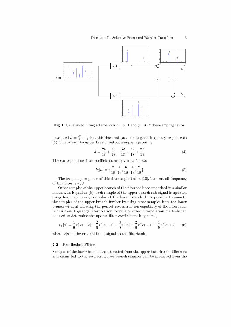
An unbalanced lazy filterbank for p = 3 : 1 and q = 3 : 2 is shown in Figure 2.In the upper-branch a regular downsampling block by a factor of three is used.In the lower-branch the downsampling block for q = 3 : 2 is used. In Figure 2,the signal x[n] is fed to the lazy filterbank and outputs of downsampling blocksare shown. Every 3rd sample of the original signal goes to the upper-branch andremaining samples appear in the lower branch.
We describe the update and the prediction filter design for the unbalancedlifting structure in the following subsection.
2.1 Update Filter
In Figure 1 an unbalanced lifting structure is shown with downsampling ratios3 : 1 and 3 : 2 in the upper and lower branches, respectively. Similar to the regularbalanced lifting filterbank case, the upper branch sample d can be estimatedusing the neighboring lower branch samples b, c, e, and f and an estimate of thesample d is given as follows:
d′ =b+ 2c+ 2e+ f
6, (2)
which is the output of the update filter linking the lower branch to the upperbranch. Since samples c and e are closer to the sample d compared to f and bmore weight is given to the samples c and e. The sample d and the output ofthe filter is linearly combined and the updated sample is obtained as follows
d =2d′
3+
d
3(3)
Since the downsampling is by a factor of three in the upper-branch original signalmust be filtered with a low-pass filter with a cut-off frequency of π/3. We could
Directionally Selective Fractional Wavelet Transform 3
-2 -1 0 1 2 3 4 5 6 70
1
2
3
4
5
6
7
8
a
b
c
d
e
f
x[n]
3:1
3:2
U
+xL
+
P
- xH
-1 0 1 20
2
4
6
8
a
d
^
^. .. . ..
. ... ..
-1 0 1 2 3 40
1
2
3
4
5
6
7
8
a
d
. ... ..
-1 0 1 2 3 4 5 6 70
1
2
3
4
5
6
7
8
b
c
e
f
. ... ..
Fig. 1. Unbalanced lifting scheme with p = 3 : 1 and q = 3 : 2 downsampling ratios.
have used d = d′
2 + d2 but this does not produce as good frequency response as
(3). Therefore, the upper branch output sample is given by
d =2b
18+
4c
18+
6d
18+
4e
18+
2f
18(4)
The corresponding filter coefficients are given as follows
hl[n] = { 2
18,4
18,6
18,4
18,2
18} (5)
The frequency response of this filter is plotted in [10]. The cut-off frequencyof this filter is π/3.
Other samples of the upper branch of the filterbank are smoothed in a similarmanner. In Equation (5), each sample of the upper branch sub-signal is updatedusing four neighboring samples of the lower branch. It is possible to smooththe samples of the upper branch further by using more samples from the lowerbranch without effecting the perfect reconstruction capability of the filterbank.In this case, Lagrange interpolation formula or other interpolation methods canbe used to determine the update filter coefficients. In general,
xL[n] =1
9x[3n− 2] +
2
9x[3n− 1] +
3
9x[3n] +
2
9x[3n+ 1] +
1
9x[3n+ 2] (6)
where x[n] is the original input signal to the filterbank.
2.2 Prediction Filter
Samples of the lower branch are estimated from the upper branch and differenceis transmitted to the receiver. Lower branch samples can be predicted from the
4 F. Keskin, A. E. Cetin
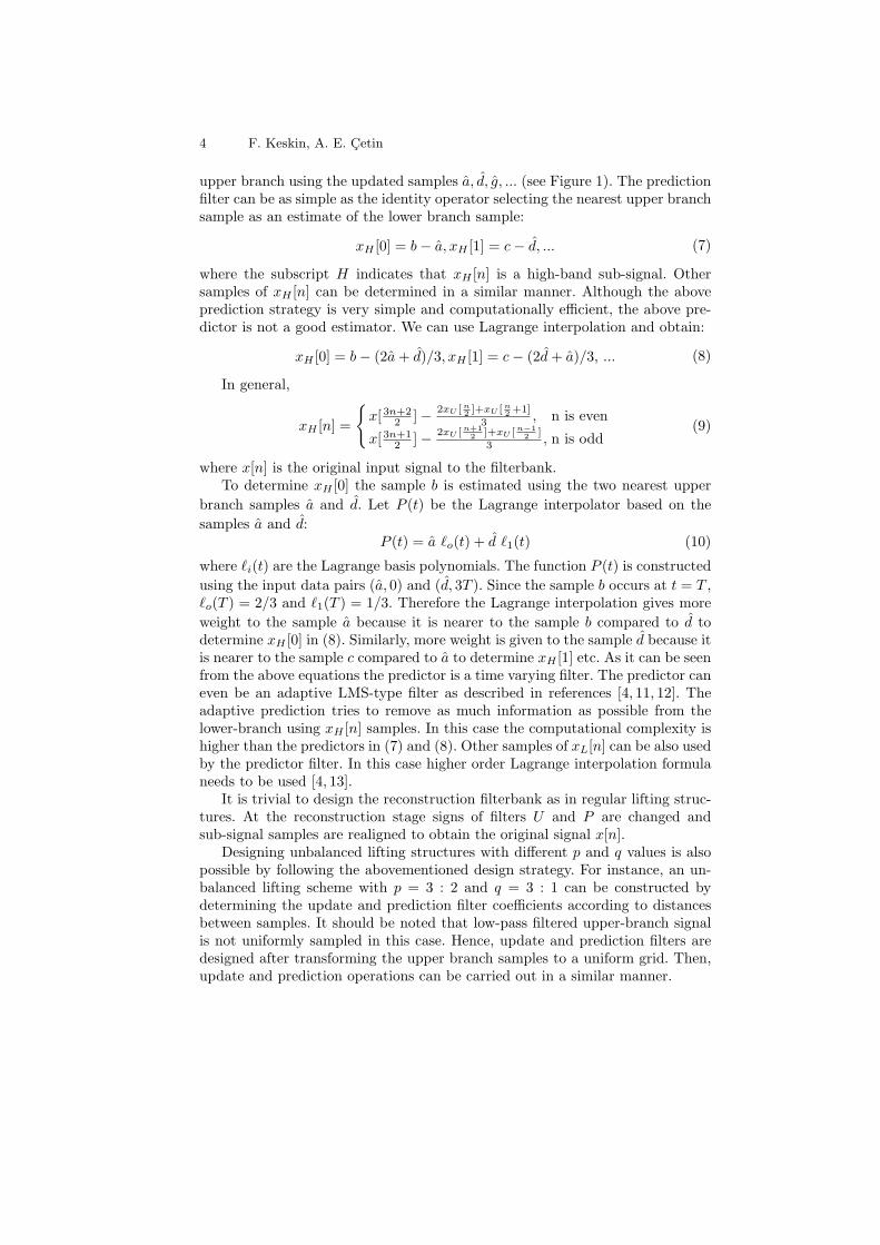
upper branch using the updated samples a, d, g, ... (see Figure 1). The predictionfilter can be as simple as the identity operator selecting the nearest upper branchsample as an estimate of the lower branch sample:
xH [0] = b− a, xH [1] = c− d, ... (7)
where the subscript H indicates that xH [n] is a high-band sub-signal. Othersamples of xH [n] can be determined in a similar manner. Although the aboveprediction strategy is very simple and computationally efficient, the above pre-dictor is not a good estimator. We can use Lagrange interpolation and obtain:
xH [0] = b− (2a+ d)/3, xH [1] = c− (2d+ a)/3, ... (8)
In general,
xH [n] =
{x[ 3n+2
2 ]− 2xU [n2 ]+xU [n2 +1]
3 , n is even
x[ 3n+12 ]− 2xU [n+1
2 ]+xU [n−12 ]
3 , n is odd(9)
where x[n] is the original input signal to the filterbank.To determine xH [0] the sample b is estimated using the two nearest upper
branch samples a and d. Let P (t) be the Lagrange interpolator based on the
samples a and d:P (t) = a ℓo(t) + d ℓ1(t) (10)
where ℓi(t) are the Lagrange basis polynomials. The function P (t) is constructed
using the input data pairs (a, 0) and (d, 3T ). Since the sample b occurs at t = T ,ℓo(T ) = 2/3 and ℓ1(T ) = 1/3. Therefore the Lagrange interpolation gives more
weight to the sample a because it is nearer to the sample b compared to d todetermine xH [0] in (8). Similarly, more weight is given to the sample d because itis nearer to the sample c compared to a to determine xH [1] etc. As it can be seenfrom the above equations the predictor is a time varying filter. The predictor caneven be an adaptive LMS-type filter as described in references [4, 11, 12]. Theadaptive prediction tries to remove as much information as possible from thelower-branch using xH [n] samples. In this case the computational complexity ishigher than the predictors in (7) and (8). Other samples of xL[n] can be also usedby the predictor filter. In this case higher order Lagrange interpolation formulaneeds to be used [4, 13].
It is trivial to design the reconstruction filterbank as in regular lifting struc-tures. At the reconstruction stage signs of filters U and P are changed andsub-signal samples are realigned to obtain the original signal x[n].
Designing unbalanced lifting structures with different p and q values is alsopossible by following the abovementioned design strategy. For instance, an un-balanced lifting scheme with p = 3 : 2 and q = 3 : 1 can be constructed bydetermining the update and prediction filter coefficients according to distancesbetween samples. It should be noted that low-pass filtered upper-branch signalis not uniformly sampled in this case. Hence, update and prediction filters aredesigned after transforming the upper branch samples to a uniform grid. Then,update and prediction operations can be carried out in a similar manner.
Directionally Selective Fractional Wavelet Transform 5
3 Extension for Two-Dimensional Signals
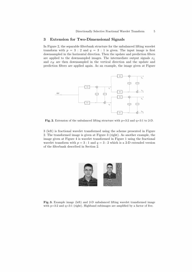
In Figure 2, the separable filterbank structure for the unbalanced lifting wavelettransform with p = 3 : 2 and q = 3 : 1 is given. The input image is firstdownsampled in the horizontal direction. Then the update and prediction filtersare applied to the downsampled images. The intermediate output signals xL
and xH are then downsampled in the vertical direction and the update andprediction filters are applied again. As an example, the image given at Figure
x[n]
3:2
3:1
U
+
+
P
-
3:2
3:1
U
+xLL
+
P
- xLH
3:2
3:1
U
+xHL
+
P
- xHH
xL
xH
Fig. 2. Extension of the unbalanced lifting structure with p=3:2 and q=3:1 to 2-D.
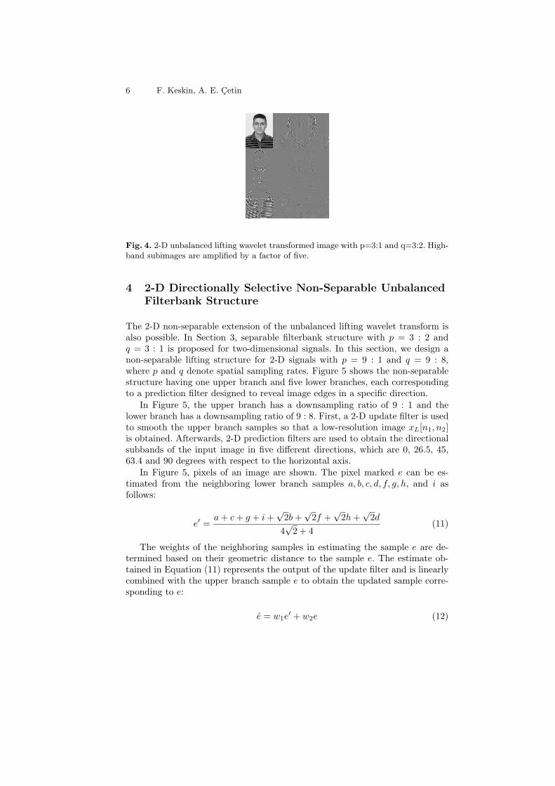
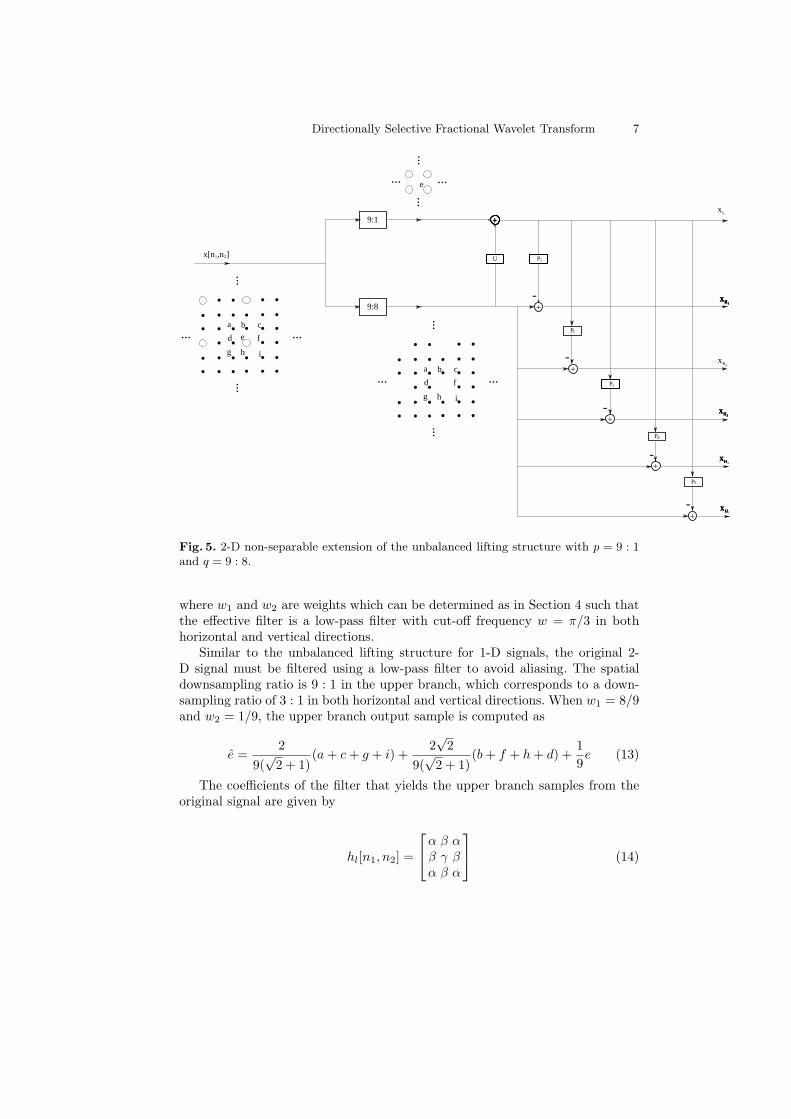
3 (left) is fractional wavelet transformed using the scheme presented in Figure2. The transformed image is given at Figure 3 (right). As another example, theimage given at Figure 4 is wavelet transformed in Figure 1 using the fractionalwavelet transform with p = 3 : 1 and q = 3 : 2 which is a 2-D extended versionof the filterbank described in Section 2.
Fig. 3. Example image (left) and 2-D unbalanced lifting wavelet transformed imagewith p=3:2 and q=3:1 (right). Highband subimages are amplified by a factor of five.
6 F. Keskin, A. E. Cetin
Fig. 4. 2-D unbalanced lifting wavelet transformed image with p=3:1 and q=3:2. High-band subimages are amplified by a factor of five.
4 2-D Directionally Selective Non-Separable UnbalancedFilterbank Structure
The 2-D non-separable extension of the unbalanced lifting wavelet transform isalso possible. In Section 3, separable filterbank structure with p = 3 : 2 andq = 3 : 1 is proposed for two-dimensional signals. In this section, we design anon-separable lifting structure for 2-D signals with p = 9 : 1 and q = 9 : 8,where p and q denote spatial sampling rates. Figure 5 shows the non-separablestructure having one upper branch and five lower branches, each correspondingto a prediction filter designed to reveal image edges in a specific direction.
In Figure 5, the upper branch has a downsampling ratio of 9 : 1 and thelower branch has a downsampling ratio of 9 : 8. First, a 2-D update filter is usedto smooth the upper branch samples so that a low-resolution image xL[n1, n2]is obtained. Afterwards, 2-D prediction filters are used to obtain the directionalsubbands of the input image in five different directions, which are 0, 26.5, 45,63.4 and 90 degrees with respect to the horizontal axis.
In Figure 5, pixels of an image are shown. The pixel marked e can be es-timated from the neighboring lower branch samples a, b, c, d, f, g, h, and i asfollows:
e′ =a+ c+ g + i+
√2b+
√2f +
√2h+
√2d
4√2 + 4
(11)
The weights of the neighboring samples in estimating the sample e are de-termined based on their geometric distance to the sample e. The estimate ob-tained in Equation (11) represents the output of the update filter and is linearlycombined with the upper branch sample e to obtain the updated sample corre-sponding to e:
e = w1e′ + w2e (12)
Directionally Selective Fractional Wavelet Transform 7
9:1
9:8
+xL
+
+++
+
-
U
+
+
+
-
-
-
- xH1
x[n1,n2] P1
P2
P3
P4
P5
xH2
xH1xH1xH1xH1
xH3xH3xH3xH3
xH4xHxHxH
xH5xHxHxH
. ... . .. .. ... . .. .
. ... . .. .. ... . .. .
a b c
d e f
g h i
......
......
. ... . .. .. ... . .. .
. ... . .. .. ... . .. .
a b c
d f
g h i
......
......
e ......
......
Fig. 5. 2-D non-separable extension of the unbalanced lifting structure with p = 9 : 1and q = 9 : 8.
where w1 and w2 are weights which can be determined as in Section 4 such thatthe effective filter is a low-pass filter with cut-off frequency w = π/3 in bothhorizontal and vertical directions.
Similar to the unbalanced lifting structure for 1-D signals, the original 2-D signal must be filtered using a low-pass filter to avoid aliasing. The spatialdownsampling ratio is 9 : 1 in the upper branch, which corresponds to a down-sampling ratio of 3 : 1 in both horizontal and vertical directions. When w1 = 8/9and w2 = 1/9, the upper branch output sample is computed as
e =2
9(√2 + 1)
(a+ c+ g + i) +2√2
9(√2 + 1)
(b+ f + h+ d) +1
9e (13)
The coefficients of the filter that yields the upper branch samples from theoriginal signal are given by
hl[n1, n2] =
α β αβ γ βα β α
(14)
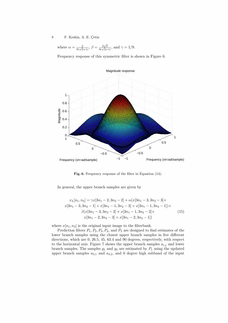
8 F. Keskin, A. E. Cetin
where α = 29(
√2+1)
, β = 2√2
9(√2+1)
, and γ = 1/9.
Frequency response of this symmetric filter is shown in Figure 6.
−1
−0.5
0
0.5
1
−1
−0.5
0
0.5
10
0.2
0.4
0.6
0.8
1
Frequency (xπ rad/sample)
Magnitude response
Frequency (xπ rad/sample)
Mag
nitu
de
Fig. 6. Frequency response of the filter in Equation (14).
In general, the upper branch samples are given by
xL[n1, n2] = γx[3n1 − 2, 3n2 − 2] + α(x[3n1 − 3, 3n2 − 3]+
x[3n1 − 3, 3n2 − 1] + x[3n1 − 1, 3n2 − 3] + x[3n1 − 1, 3n2 − 1])+
β(x[3n1 − 3, 3n2 − 2] + x[3n1 − 1, 3n2 − 2]+ (15)
x[3n1 − 2, 3n2 − 3] + x[3n1 − 2, 3n2 − 1])
where x[n1, n2] is the original input image to the filterbank.Prediction filters P1, P2, P3, P4, and P5 are designed to find estimates of the
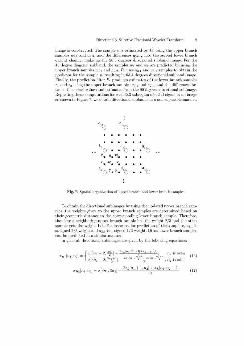
lower branch samples using the closest upper branch samples in five differentdirections, which are 0, 26.5, 45, 63.4 and 90 degrees, respectively, with respectto the horizontal axis. Figure 7 shows the upper branch samples ai,j and lowerbranch samples. The samples y1 and y2 are estimated by P1 using the updatedupper branch samples a3,1 and a3,2, and 0 degree high subband of the input
Directionally Selective Fractional Wavelet Transform 9
image is constructed. The sample v is estimated by P2 using the upper branchsamples a3,1 and a2,3, and the differences going into the second lower branchoutput channel make up the 26.5 degrees directional subband image. For the45 degree diagonal subband, the samples w1 and w2 are predicted by using theupper branch samples a3,1 and a2,2. P4 uses a3,1 and a1,2 samples to obtain thepredictor for the sample u, resulting in 63.4 degrees directional subband image.Finally, the prediction filter P5 produces estimates of the lower branch samplesz1 and z2 using the upper branch samples a3,1 and a2,1, and the differences be-tween the actual values and estimates form the 90 degrees directional subimage.Repeating these computations for each 3x3 subregion of a 2-D signal or an imageas shown in Figure 7, we obtain directional subbands in a non-separable manner.
....
.. .. ....
.. ..
....
.. .. ....
.. .....
...
... ...
a1,1
a2,1
a3,1
a1,2
a2,2
a3,2
a3,3
a2,3
1 y2
z1
z2
w1
w2
y
v
u
Fig. 7. Spatial organization of upper branch and lower branch samples.
To obtain the directional subimages by using the updated upper branch sam-ples, the weights given to the upper branch samples are determined based ontheir geometric distance to the corresponding lower branch sample. Therefore,the closest neighboring upper branch sample has the weight 2/3 and the othersample gets the weight 1/3. For instance, for prediction of the sample v, a3,1 isassigned 2/3 weight and a2,3 is assigned 1/3 weight. Other lower branch samplescan be predicted in a similar manner.
In general, directional subimages are given by the following equations:
xH1 [n1, n2] =
{x[3n1 − 2, 3n2
2 ]− 2xL[n1,n22 +1]+xL[n1,
n22 ]
3 , n2 is even
x[3n1 − 2, 3n2+12 ]− 2xL[n1,
n2+12 ]+xL[n1,
n2+32 ]
3 , n2 is odd(16)
xH2 [n1, n2] = x[3n1, 3n2]−2xL[n1 + 1, n2] + xL[n1, n2 + 2]
3(17)
10 F. Keskin, A. E. Cetin
xH3 [n1, n2] =
{x[3n1,
3n2+12 ]− 2xL[n1+1,
n2+12 ]+xL[n1,
n2+32 ]
3 , n2 is odd
x[3n1 − 1, 3n2
2 ]− 2xL[n1,n22 +1]+xL[n1+1,
n22 ]
3 , n2 is even(18)
xH4 [n1, n2] = x[3n1 − 1, 3n2 − 1]− 2xL[n1 + 1, n2] + xL[n1 − 1, n2 + 1]
3(19)
xH5 [n1, n2] =
{x[ 3n1
2 , 3n2 − 2]− 2xL[n12 +1,n2]+xL[
n12 ,n2]
3 , n1 is even
x[ 3n1+12 , 3n2 − 2]− 2xL[
n1+12 ,n2]+xL[
n1+32 ,n2]
3 , n1 is odd(20)
It is also possible to use the four closest neighboring upper branch samplesin the desired direction instead of the two closest samples to estimate the lowerbranch sample. Then, the weights of the updated upper branch samples areassigned accordingly. More robust estimates of the lower branch samples canbe achieved by adopting this prediction strategy. Other possibility is to use theadaptive filters in [6] and [7] for predicting the lower branch samples.
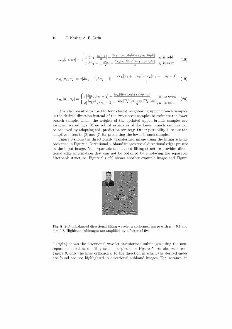
Figure 8 shows the directionally transformed image using the lifting schemepresented in Figure 5. Directional subband images reveal directional edges presentin the input image. Non-separable unbalanced lifting structure provides direc-tional edge information that can not be obtained by employing the separablefilterbank structure. Figure 9 (left) shows another example image and Figure
Fig. 8. 2-D unbalanced directional lifting wavelet transformed image with p = 9:1 andq = 9:8. Highband subimages are amplified by a factor of five.
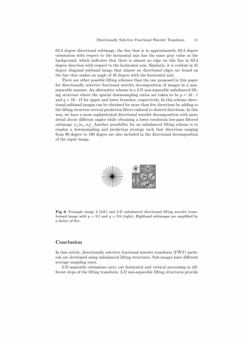
9 (right) shows the directional wavelet transformed subimages using the non-separable unbalanced lifting scheme depicted in Figure 5. As observed fromFigure 9, only the lines orthogonal to the direction in which the desired egdesare found are not highlighted in directional subband images. For instance, in
Directionally Selective Fractional Wavelet Transform 11
63.4 degree directional subimage, the line that is in approximately 63.4 degreeorientation with respect to the horizontal axis has the same gray value as thebackground, which indicates that there is almost no edge on this line in 63.4degree direction with respect to the horizontal axis. Similarly, it is evident in 45degree diagonal subband image that almost no directional edges are found onthe line that makes an angle of 45 degree with the horizontal axis.
There are other possible lifting schemes than the one proposed in this paperfor directionally selective fractional wavelet decomposition of images in a non-separable manner. An alternative scheme is a 2-D non-separable unbalanced lift-ing structure where the spatial downsampling ratios are taken to be p = 16 : 1and q = 16 : 15 for upper and lower branches, respectively. In this scheme direc-tional subband images can be obtained for more than five directions by adding tothe lifting structure several prediction filters tailored to desired directions. In thisway, we have a more sophisticated directional wavelet decomposition with moredetail about different angles while obtaining a lower resolution low-pass filteredsubimage xL[n1, n2]. Another possibility for an unbalanced lifting scheme is toemploy a downsampling and prediction strategy such that directions rangingfrom 90 degree to 180 degree are also included in the directional decompositionof the input image.
Fig. 9. Example image 2 (left) and 2-D unbalanced directional lifting wavelet trans-formed image with p = 9:1 and q = 9:8 (right). Highband subimages are amplified bya factor of five.
Conclusion
In this article, directionally selective fractional wavelet transform (FWT) meth-ods are developed using unbalanced lifting structures. Sub-images have differentaverage sampling rates.
2-D separable extensions carry out horizontal and vertical processing in dif-ferent steps of the lifting transform. 2-D non-separable lifting structures provide
12 F. Keskin, A. E. Cetin
unbalanced directional decomposition of the input image, leading to many differ-ent directional subbands. Image transformation examples are presented for bothseparable and non-separable cases. The FWT method can be easily extended tohigher dimensions.
References
1. Mallat, S.: A Wavelet Tour of Signal Processing, Second Edition (Wavelet Analysis& Its Applications). Academic Press (1999)
2. Sweldens, W.: The lifting scheme: A custom-design construction of biorthogonalwavelets. Applied and Computational Harmonic Analysis 3 (1996) 186 – 200
3. Daubechies, I., Sweldens, W.: Factoring wavelet transforms into lifting steps. Jour-nal of Fourier Analysis and Applications 4 (1998) 247–269
4. Kim, C.W., Ansari, R., Cetin, A.E.: A class of linear-phase regular biorthogo-nal wavelets. In: Acoustics, Speech, and Signal Processing, IEEE InternationalConference on. Volume 4. (1992) 673 –676
5. Hampson, F.J., Pesquet, J.C.: A nonlinear subband decomposition with perfectreconstruction. In: Acoustics, Speech, and Signal Processing, IEEE InternationalConference on. Volume 3. (1996) 1523 –1526
6. Gerek, O.N., Cetin, A.E.: Adaptive polyphase subband decomposition structuresfor image compression. IEEE Transactions on Image Processing 9 (2000) 1649–1660
7. Gerek, O.N., Cetin, A.E.: A 2-d orientation-adaptive prediction filter in liftingstructures for image coding. IEEE Transactions on Image Processing 15 (2006)106 –111
8. Le Pennec, E., Mallat, S.: Image compression with geometrical wavelets. In: ImageProcessing, International Conference on. Volume 1. (2000) 661 –664
9. Claypoole, R.L., Davis, G.M., Sweldens, W., Baraniuk, R.G.: Nonlinear wavelettransforms for image coding via lifting. IEEE Transactions on Image Processing12 (2003) 1449 – 1459
10. Habiboglu, Y.H., K.K., Cetin, A.E.: Fractional wavelet transform using an unbal-anced lifting structure. In: Independent Component Analyses, Wavelets, NeuralNetworks, Biosystems, and Nanoengineering IX, Proc. SPIE 8058. (2011)
11. Pesquet-Popescu, B., Bottreau, V.: Three-dimensional lifting schemes for motioncompensated video compression. In: Acoustics, Speech, and Signal Processing,IEEE International Conference on. Volume 3. (2001) 1793 –1796
12. Piella, G., Pesquet-Popescu, B., Heijmans, H.: Adaptive update lifting with adecision rule based on derivative filters. IEEE Signal Processing Letters 9 (2002)329 – 332
13. Heller, P.: Lagrange m-th band filters and the construction of smooth m-bandwavelets. In: Time-Frequency and Time-Scale Analysis, 1994. Proceedings of theIEEE-SP International Symposium on. (1994) 108 –111