Embed Size (px)
Citation preview
Direct Design Method Based on Ideal Forming Theory for Hydroforming and Flanging Processes
Kwansoo Chung 1 and Jeong Whan Yoon 2,3
1 School of Materials Science & Eng., Seoul National Univ., Kwanak-Ku, Seoul, 151-742, KOREA 2 Materials Science Division, Alcoa Technical Center, 100 Technical Drive, Alcoa Center, PA 15069-0001, USA
3 Dept. of Mechanical Eng., Univ. of Aveiro, Aveiro 3810, Portugal
Abstract. Conventional practices to predict preform shapes in hydroformimg and flanging processes are based on FEM analysis and/or experiment, which require many trials. In an effort to effectively improve the design procedure by overcoming the indirect nature of the conventional design tools, a direct design method based on the ideal forming theory has been previously developed as a newly added design tool in the design procedure. Here, the direct design method based on the ideal forming theory was applied to the preform design for hydroforming and flanging operations. In order to account for anisotropy, the anisotropic strain rate potential which simultaneously accounts for the anisotropy of yield stress as well as the anisotropy of plastic strain ratio was used as a part of the constitutive equation.
INTRODUCTION
In order to improve conventional trial-and-error based practices for optimizing forming processes, a direct design method, called the ideal forming theory, has been previously developed [1 - 4]. In this theory, materials are prescribed to deform following the proportional true strain path (or the minimum plastic work path for isotropic materials having smooth yield surfaces) and then the initial blank shape is obtained from a one-step backward calculation in which the final sheet product shape is specified. The theory can be used to determine an ideal initial blank shape or preform shape needed to achieve a specified final shape while resulting in optimum strain distributions. Because of its assumed deformation path, the result of the theory does not completely comply with real forming so that it is used to guide the iterative design procedure based on analytic methods.
The direct design method usually has been applied
for flat blanks in stamping processes for blank design [5] or rapid evaluation of strain distributions [6], while the method also has been applied for non-flat blanks recently [7]. In this work, the method was applied to design a preform for hydorforming of hollow structures utilizing the method developed for non-flat blanks. Also, the one-step forward method based on
the direct design method was developed for flanging operation applications. Application examples of industrial parts for hydroforming and flanging processes are presented in this work to show the efficiency and robustness of the proposed direct design method.
IDEAL FORMING DESIGN THEORY FOR NON-FLAT BLANK
When materials are discretized with meshes and the surface traction is approximated by point forces, the plastic work is a function of the initial position vectors X and the final position vectors x:
1,2,3 1,2( , )e i iW W x X= = = ε . (1)
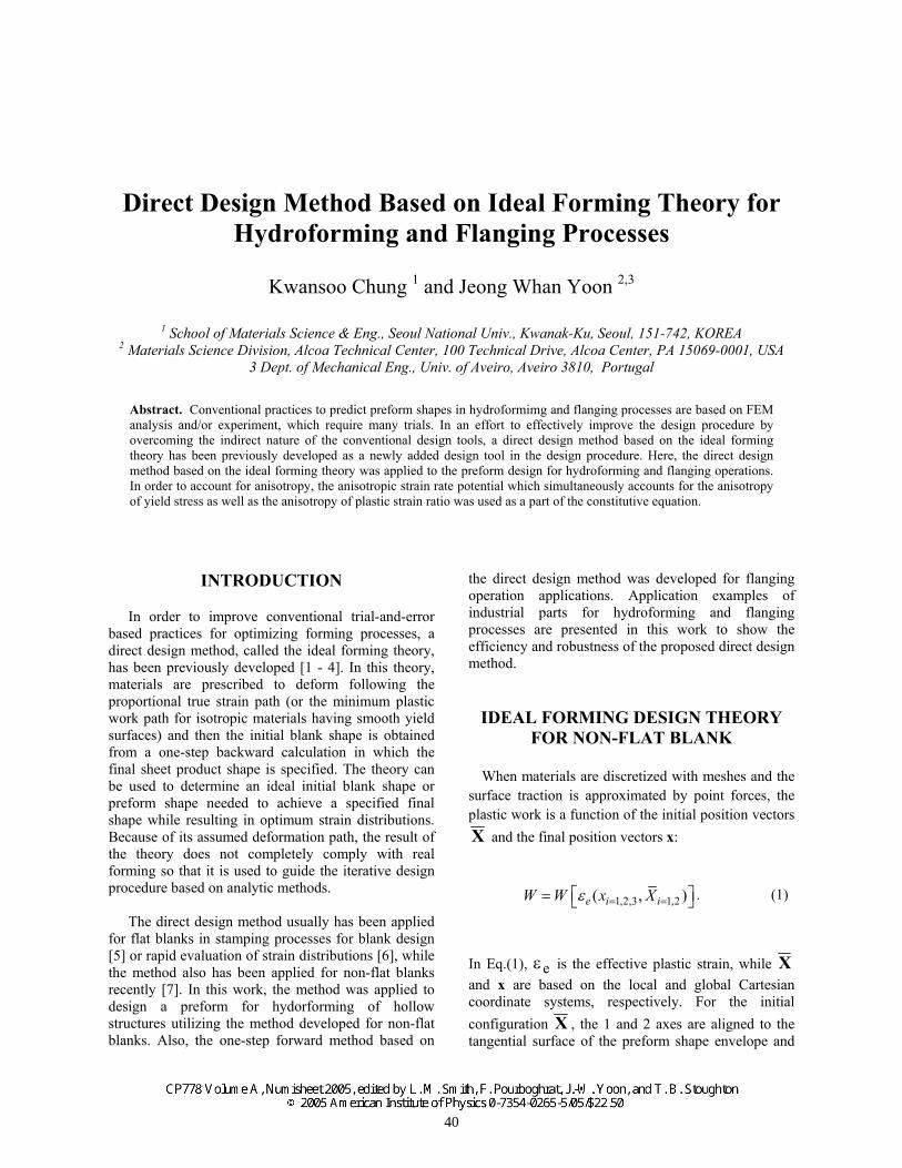
In Eq.(1), εe is the effective plastic strain, while X and x are based on the local and global Cartesian coordinate systems, respectively. For the initial configuration X , the 1 and 2 axes are aligned to the tangential surface of the preform shape envelope and
40
the 3-axis is normal to the surface as shown in Fig.1.
In Eq.(1), the value of the effective strain εe is dependent on the deformation paths of material elements and so is the plastic work. In the ideal forming theory, the minimum plastic work path is imposed for each material. The minimum plastic work path for materials having smooth yield surfaces is equivalent to the proportional true strain path, whose principal directions are restricted to be aligned with specific material directions for anisotropic materials. However, in this design theory, the principal directions are allowed to be arbitrary. When the proportional true strain path is imposed, the effective strain in Eq.(1), obtained from the effective strain-rate by substituting the rate of deformation tensor with the true strain tensor, becomes a function of x and X . Note that the effective strain is obtained from the flow theory by applying the deformation theory based on the minimum plastic work path [8]. When the final sheet product shape is prescribed, the final configuration is specified so that the plastic work in Eq. (1) is a function of X only. Also, the initial position is constrained to stay on the initial blank envelope prescribed in advance in the design stage, therefore, the third component of X always vanishes and W is a function of the first two components of X .
The preform shape is obtained by optimizing the plastic work on the prescribed non-flat envelope surface; i.e.,
ee e o n
dW ( ) dV d
∂ε= σ ε = µ ⋅
∂∫ f s FX X
(2)
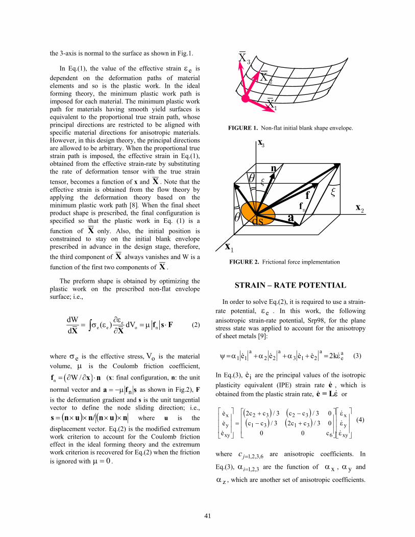
where σe is the effective stress, Vo is the material volume, µ is the Coulomb friction coefficient,
( )n W /= ∂ ∂ ⋅f x n (x: final configuration, n: the unit
normal vector and a f s= −µ n as shown in Fig.2), F is the deformation gradient and s is the unit tangential vector to define the node sliding direction; i.e.,
( ) ( ) nunn/uns ××××= where u is the displacement vector. Eq.(2) is the modified extremum work criterion to account for the Coulomb friction effect in the ideal forming theory and the extremum work criterion is recovered for Eq.(2) when the friction is ignored with 0µ = .
FIGURE 1. Non-flat initial blank shape envelope.
FIGURE 2. Frictional force implementation
STRAIN – RATE POTENTIAL
In order to solve Eq.(2), it is required to use a strain-rate potential, εe . In this work, the following anisotropic strain-rate potential, Srp98, for the plane stress state was applied to account for the anisotropy of sheet metals [9]:
ψ α α α ε= + + + =1 1 2 2 3 1 2 2e e e e ka a a
ea (3)
In Eq.(3), ei are the principal values of the isotropic plasticity equivalent (IPE) strain rate e , which is obtained from the plastic strain rate, e = Lε or
( ) ( )( ) ( )
/ // /
eee
c c c cc c c c
c
x
y
xy
x
y
xy
=
+ −− +
2 3 3 03 2 3 0
0 0
2 3 2 3
1 3 1 3
6
εεε
(4)
where 1,2,3,6jc = are anisotropic coefficients. In
Eq.(3), 1,2,3i=α are the function of αx , αy and
αz , which are another set of anisotropic coefficients.
2X
3X
1X
3x
n
a 2a
ds
ξ
θ
fnf
ξθ
1x
2x
41
For isotropic materials, all the anisitropic coefficients become identical, typically with the value of 1.0. The exponent a in Eq.(3) is used to match the shapes of strain-rate potentials with those calculated from polycrystal models. For FCC and BCC polycrystals, the exponents are 4/3 and 3/2, respectively. The value k in Eq.(3) is a constant to accommodate the difference between the reference strain-rate state being used to define the effective strain rate with that being used for the stress-strain hardening curve.
PREFORM DESIGN FOR HYDROFOMING PROCESSESS
In the preform optimization for hydroforming processes, the preform shape is assumed straight with a uniform cross section as an extruded part. Therefore, if the constraint that all initial positions stay on the initial surface envelope is imposed, Eq.(2) can be replaced with the following equation utilizing the penalty constraint method, especially when the friction condition is ignored:
nnode-nseci i+nsect 23 3
i=11,2,3
1W( ) C X X 0X 2∂ + ∂
∑t
X ( - ) =
(5)
where i=1~nsect3X 0= and “nsect” is the total number
of nodes in the cross section and “nnode” is the total number of nodes. Eq.(5) is a nonlinear equation for initial preform optimization with three degrees of freedom per a node. The Newton-Raphson method was used to solve Eq.(5).
FIGURE 3. Schematic view of the local coordinate system defined for a node set in the initial configuration
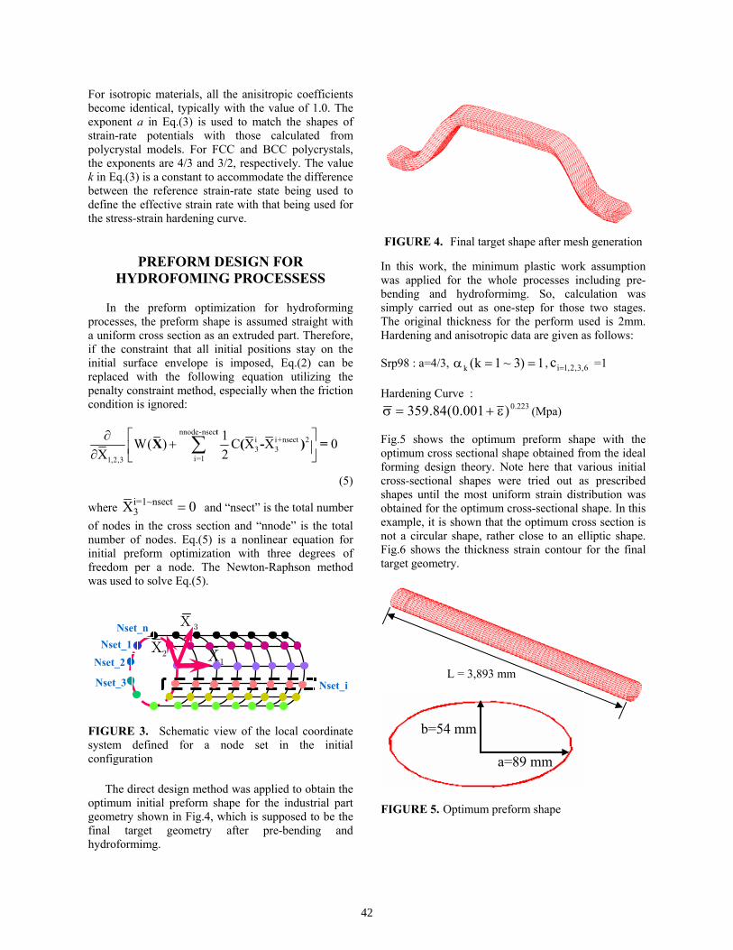
The direct design method was applied to obtain the optimum initial preform shape for the industrial part geometry shown in Fig.4, which is supposed to be the final target geometry after pre-bending and hydroformimg.
FIGURE 4. Final target shape after mesh generation
In this work, the minimum plastic work assumption was applied for the whole processes including pre-bending and hydroformimg. So, calculation was simply carried out as one-step for those two stages. The original thickness for the perform used is 2mm. Hardening and anisotropic data are given as follows:
Srp98 : a=4/3, 1)3~1k(k ==α , 6,3,2,1ic = =1
Hardening Curve : 223.0)001.0(84.359 ε+=σ (Mpa)
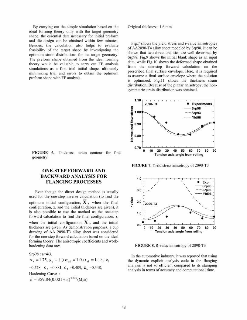
Fig.5 shows the optimum preform shape with the optimum cross sectional shape obtained from the ideal forming design theory. Note here that various initial cross-sectional shapes were tried out as prescribed shapes until the most uniform strain distribution was obtained for the optimum cross-sectional shape. In this example, it is shown that the optimum cross section is not a circular shape, rather close to an elliptic shape. Fig.6 shows the thickness strain contour for the final target geometry.
FIGURE 5. Optimum preform shape
1X2X
Nset_i
Nset_1
Nset_2
Nset_3
Nset_n
L = 3,893 mm
3X
b=54 mm
a=89 mm
42
By carrying out the simple simulation based on theideal forming theory only with the target geometryshape, the essential data necessary for initial preformand die design can be obtained within few minutes.Besides, the calculation also helps to evaluatefeasibility of the target shape by investigating theoptimum strain distributions for the target geometry.The preform shape obtained from the ideal formingtheory would be valuable to carry out FE analysissimulations as a first trial initial shape, ultimatelyminimizing trial and errors to obtain the optimumpreform shape with FE analysis.
Original thickness: 1.6mm
Fig.7 shows the yield stress and r-value anisotropiesof AA2090-T4 alloy sheet modeled by Srp98. It can beshown that two directionalities are well described bySrp98. Fig,9 shows the initial blank shape as an inputdata, while Fig. 10 shows the deformed shape obtainedfrom the one-step forward calculation on theprescribed final surface envelope. Here, it is requiredto assume a final surface envelope where the solutionis optimized. Fig. 11 shows the thickness straindistribution. Because of the planar anisotropy, the non-symmetric strain distribution was obtained.
1.102090-T3
FIGURE 6. Thickness strain contour for finalgeometry
ONE-STEP FORWARD ANDBACKWARD ANALYSIS FOR
FLANGING PROCESSES
Even though the direct design method is usuallyused for the one-step inverse calculation (to find theoptimum initial configuration, X , when the finalconfiguration, x, and the initial thickness are given), itis also possible to use the method as the one-stepforward calculation to find the final configuration, x,when the initial configuration, X , and the initialthickness are given. As demonstration purposes, a cupdrawing of AA 2090-T3 alloy sheet was consideredfor the one-step forward calculation based on the idealforming theory. The anisotropic coefficients and work-hardening data are:
Srp98 : a-4/3,ocx =1.75,ay =3.0 az0 -1.0 azl -1.15, c^-0.528, C2 -0.881, C3 -0.409, C6 -0.348,Hardening Curve :a - 359.84(0.001 + s)°223 (Mpa)
> Experiments-Srp98- Srp93-Yld96
0.700 10 20 30 40 50 60 70 80 90
Tension axis angle from rolling
FIGURE 7. Yield stress anisotropy of 2090-T3
4.0
3.0
« 2.0
1.0
0.00 10 20 30 40 50 60 70 80 90
Tension axis angle from rolling
FIGURE 8. R-value anisotropy of 2090-T3
In the automotive industry, it was reported that usingthe dynamic explicit analysis code in the flanginganalysis is not so efficient compared to its stampinganalysis in terms of accuracy and computational time.
43

FIGURE 9. Initial blank shape as an input
FIGURE 10. The deformed shape on the prescribed initial surface envelope obtained from the one-step
forward calculation
FIGURE 11. Thickness strain distribution on the deformed shape
Therefore, using the one-step forward and backward calculations based on the ideal forming
theory might be an efficient approach to resolve the drawbacks of dynamic explicit codes for flanging analysis. Here, the one-step forward and backward calculations were performed to design the optimum trimming line before flanging. Fig.12 shows the final target geometry after flanging. Usually, in the automotive industry, the initial trial blank shape is obtained based on CAD predictions, neglecting material deformation. Fig.13 shows the blank shape obtained from CAD for the final target geometry shown in Fig.12.
Rather than performing expensive dynamic explicit calculation, the one-step forward calculation was employed in order to check the validity of the blank shape designed using CAD calculation. Fig. 14 shows the one-step forward solution on the prescribed flanging surface envelope and Fig. 15 shows the significant difference between the target geometry and the one-step forward solution obtained utilizing the blank obtained from CAD, indirectly confirming that the blank shape obtained from CAD would not be so useful as expected to form the target geometry.
FIGURE 12. Final target shape after flanging
FIGURE 13. Initial blank shape obtained from CAD
44
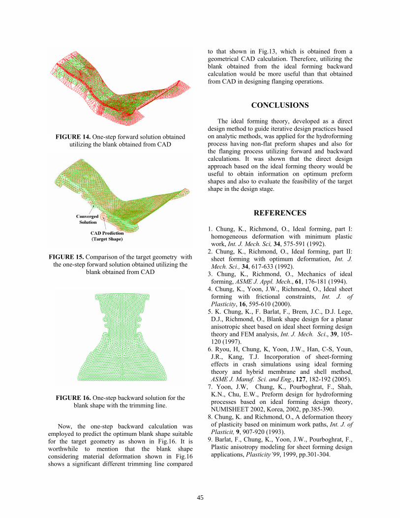
FIGURE 14. One-step forward solution obtained
utilizing the blank obtained from CAD
FIGURE 15. Comparison of the target geometry with the one-step forward solution obtained utilizing the
blank obtained from CAD
FIGURE 16. One-step backward solution for the blank shape with the trimming line.
Now, the one-step backward calculation was employed to predict the optimum blank shape suitable for the target geometry as shown in Fig.16. It is worthwhile to mention that the blank shape considering material deformation shown in Fig.16 shows a significant different trimming line compared
to that shown in Fig.13, which is obtained from a geometrical CAD calculation. Therefore, utilizing the blank obtained from the ideal forming backward calculation would be more useful than that obtained from CAD in designing flanging operations.
CONCLUSIONS
The ideal forming theory, developed as a direct design method to guide iterative design practices based on analytic methods, was applied for the hydroforming process having non-flat preform shapes and also for the flanging process utilizing forward and backward calculations. It was shown that the direct design approach based on the ideal forming theory would be useful to obtain information on optimum preform shapes and also to evaluate the feasibility of the target shape in the design stage.
REFERENCES
1. Chung, K., Richmond, O., Ideal forming, part I: homogeneous deformation with minimum plastic work, Int. J. Mech. Sci, 34, 575-591 (1992).
2. Chung, K., Richmond, O., Ideal forming, part II: sheet forming with optimum deformation, Int. J. Mech. Sci., 34, 617-633 (1992).
3. Chung, K., Richmond, O., Mechanics of ideal forming, ASME J. Appl. Mech., 61, 176-181 (1994).
4. Chung, K., Yoon, J.W., Richmond, O., Ideal sheet forming with frictional constraints, Int. J. of Plasticity, 16, 595-610 (2000).
5. K. Chung, K., F. Barlat, F., Brem, J.C., D.J. Lege, D.J., Richmond, O., Blank shape design for a planar anisotropic sheet based on ideal sheet forming design theory and FEM analysis, Int. J. Mech. Sci., 39, 105-120 (1997).
6. Ryou, H, Chung, K, Yoon, J.W., Han, C-S, Youn, J.R., Kang, T.J. Incorporation of sheet-forming effects in crash simulations using ideal forming theory and hybrid membrane and shell method, ASME J. Manuf. Sci. and Eng., 127, 182-192 (2005).
7. Yoon, J.W, Chung, K., Pourboghrat, F., Shah, K.N., Chu, E.W., Preform design for hydroforming processes based on ideal forming design theory, NUMISHEET 2002, Korea, 2002, pp.385-390.
8. Chung, K. and Richmond, O., A deformation theory of plasticity based on minimum work paths, Int. J. of Plasticit, 9, 907-920 (1993).
9. Barlat, F., Chung, K., Yoon, J.W., Pourboghrat, F., Plastic anisotropy modeling for sheet forming design applications, Plasticity’99, 1999, pp.301-304.
45


![Chemical Secret Stage4[Ekitap,eBook]](https://img.dokumen.tips/doc/110x75/5695d2b91a28ab9b029b7a97/chemical-secret-stage4ekitapebook.jpg)
