Embed Size (px)
Citation preview
7/25/2019 DIN en 15011-2011 - Cranes - Bridge and Gantry Cranes
http://slidepdf.com/reader/full/din-en-15011-2011-cranes-bridge-and-gantry-cranes 1/95
May 2011
Translation by DIN-Sprachendienst.
English price group 30No part of this translation may be reproduced without prior permission of DIN Deutsches Institut für Normung e. V., Berlin. Beuth Verlag GmbH, 10772 Berlin, Germany,has the exclusive right of sale for German Standards (DIN-Normen).
ICS 53.020.20
!$p_o"1776076
www.din.de
DDIN EN 15011
Cranes –
Bridge and gantry cranes
English translation of DIN EN 15011:2011-05
Krane –Brücken- und Portalkrane
Englische Übersetzung von DIN EN 15011:2011-05 Appareils de levage à charge suspendue –Ponts roulants et portiquesTraduction anglaise de DIN EN 15011:2011-05
©
www.beuth.de
Document comprises pages
In case of doubt, the German-language original shall be considered authoritative.
95
04.11

7/25/2019 DIN en 15011-2011 - Cranes - Bridge and Gantry Cranes
http://slidepdf.com/reader/full/din-en-15011-2011-cranes-bridge-and-gantry-cranes 2/95
DIN EN 15011:2011-05
A comma is used as the decimal marker.
Start of application
The start of application of this standard is 1 May 2011.
National foreword
This standard includes safety requirements.
This standard has been prepared by Technical Committee CEN/TC 147 “Cranes — Safety”, (Secretariat: BSI,
United Kingdom).
The responsible German body involved in its preparation was the Normenausschuss Maschinenbau
(Mechanical Engineering Standards Committee), Steering Group CEN/TC 147 – ISO/TC 96 – Krane.
It should be noted that the term “crane” as in this standard includes all machines for cyclic lifting, or cyclic
lifting and handling, of loads suspended on hooks or other load lifting attachments. This means that this
standard applies to all other equipment, such as winches, which meets this definition.
This standard contains specifications meeting the essential requirements set out in Annex I of the “Machinery
Directive”, Directive 2006/42/EC, and which apply to machines that are either first placed on the market or
commissioned within the EEA. This standard serves to facilitate proof of compliance with the essential
requirements of the directive.
Once this standard is cited in the Official Journal of the European Union, it is deemed a “harmonized”
standard and thus, a manufacturer applying this standard may assume compliance with the requirements of
the Machinery Directive (“presumption of conformity”).
The European Standards referred to in Clause 2 and in the Bibliography of this document have been
published as the corresponding DIN EN or DIN EN ISO Standards with the same number. The International
Standards and publications referred to in this document have been published as the corresponding DIN ISO
Standards with the same number, except for those below, which correspond as follows:
ISO 6336-1:2006 DIN 3990-1:1987-12 (similar)
ISO 7752-5 DIN 15025:1978-01 (similar)
National Annex NA(informative)
Bibliography
DIN 3990-1:1987-12, Calculation of load capacity of cylindrical gears — Introduction and general influence
factors
DIN 15025:1978-01, Cranes — Direction of actuation and arrangement of controls in crane cabins
2

7/25/2019 DIN en 15011-2011 - Cranes - Bridge and Gantry Cranes
http://slidepdf.com/reader/full/din-en-15011-2011-cranes-bridge-and-gantry-cranes 3/95
EUROPEAN STANDARD
NORME EUROPÉENNE
EUROPÄISCHE NORM
EN 15011
January 2011
ICS 53.020.20
English Version
Cranes —Bridge and gantry cranes
Appareils de levage à charge suspendue —Ponts roulants et portiques
Krane —Brücken- und Portalkrane
This European Standard was approved by CEN on 18 December 2010.
CEN members are bound to comply with the CEN/CENELEC Internal Regulations which stipulate the conditions for giving this EuropeanStandard the status of a national standard without any alteration. Up-to-date lists and bibliographical references concerning such nationalstandards may be obtained on application to the CEN-CENELEC Management Centre or to any CEN member.
This European Standard exists in three official versions (English, French, German). A version in any other language made by translationunder the responsibility of a CEN member into its own language and notified to the CEN-CENELEC Management Centre has the samestatus as the official versions.
CEN members are the national standards bodies of Austria, Belgium, Bulgaria, Croatia, Cyprus, Czech Republic, Denmark, Estonia,Finland, France, Germany, Greece, Hungary, Iceland, Ireland, Italy, Latvia, Lithuania, Luxembourg, Malta, Netherlands, Norway, Poland,Portugal, Romania, Slovakia, Slovenia, Spain, Sweden, Switzerland and United Kingdom.
EUROPEAN COMMITTEE FOR STANDARDIZATION
COM IT É E UROPÉ E N DE NORM AL ISAT ION
EUROPÄISCHES KOMITEE FÜR NORMUNG
Management Centre: Avenue Marnix 17, B-1000 Brussels
© 2011 CEN All rights of exploitation in any form and by any means reservedworldwide for CEN national Members.
Ref. No. EN 15011:2011: E

7/25/2019 DIN en 15011-2011 - Cranes - Bridge and Gantry Cranes
http://slidepdf.com/reader/full/din-en-15011-2011-cranes-bridge-and-gantry-cranes 4/95
EN 15011:2011 (E)
2
Contents
Page Foreword ..............................................................................................................................................................3
Introduction .........................................................................................................................................................4
1 Scope ......................................................................................................................................................5
2 Normative references ............................................................................................................................5
3 Terms and definitions ...........................................................................................................................7
4
List of significant hazards ....................................................................................................................8
5 Safety requirements and/or protective measures ........................................................................... 14
5.1
General ................................................................................................................................................. 14
5.2
Requirements for strength and stability .......................................................................................... 14
5.3 Electrotechnical equipment ............................................................................................................... 28
5.4
Non-electrotechnical equipment ....................................................................................................... 30
5.5 Limiting and indicating devices ........................................................................................................ 36
5.6 Man-machine interface ....................................................................................................................... 39
5.7 Equipment for warning ....................................................................................................................... 42
6 Verification of safety requirements and/or protective measures .................................................. 43
6.1
General ................................................................................................................................................. 43
6.2
Types of verification ........................................................................................................................... 44
6.3 Fitness for purpose testing ............................................................................................................... 46
7 Information for use ............................................................................................................................. 48
7.1 General ................................................................................................................................................. 48
7.2
Operator’s manual .............................................................................................................................. 49
7.3
User’s manual ..................................................................................................................................... 49
7.4 Marking of rated capacities ............................................................................................................... 51
Annex A (informative) Guidance for specifying the operating duty according to EN 13001-1 ................ 53
Annex B (informative) Guidance for specifying the classes P of average number of accelerationsaccording to EN 13001-1 .................................................................................................................... 62
Annex C (informative) Calculation of dynamic coefficient φφφφh(t) ................................................................... 63
Annex D (normative) Loads caused by skewing .......................................................................................... 66
Annex E (informative) Calculation of stall load factor for indirect acting lifting force limiter .................. 73
Annex F (informative) Local stresses in wheel supporting flanges ............................................................ 75
Annex G (normative) Noise test code ............................................................................................................ 80
Annex H (informative) Actions on crane supporting structures induced by cranes ................................ 89
Annex I (informative) Selection of a suitable set of crane standards for a given application .................. 91
Annex ZA (informative) Relationship between this European standard and the EssentialRequirements of EU Directive 2006/42/EC ....................................................................................... 92
Bibliography ..................................................................................................................................................... 93
DIN EN 15011:2011-05

7/25/2019 DIN en 15011-2011 - Cranes - Bridge and Gantry Cranes
http://slidepdf.com/reader/full/din-en-15011-2011-cranes-bridge-and-gantry-cranes 5/95
EN 15011:2011 (E)
3
Foreword
This document (EN 15011:2011) has been prepared by Technical Committee CEN/TC 147 “Cranes - Safety”,the secretariat of which is held by BSI.
This European Standard shall be given the status of a national standard, either by publication of an identicaltext or by endorsement, at the latest by July 2011, and conflicting national standards shall be withdrawn at thelatest by July 2011.
Attention is drawn to the possibility that some of the elements of this document may be the subject of patentrights. CEN [and/or CENELEC] shall not be held responsible for identifying any or all such patent rights.
This document has been prepared under a mandate given to CEN by the European Commission and the
European Free Trade Association, and supports essential requirements of EU Directive(s).
For relationship with EU Directive(s), see informative Annex ZA, which is an integral part of this document.
According to the CEN/CENELEC Internal Regulations, the national standards organizations of the followingcountries are bound to implement this European Standard: Austria, Belgium, Bulgaria, Croatia, Cyprus, CzechRepublic, Denmark, Estonia, Finland, France, Germany, Greece, Hungary, Iceland, Ireland, Italy, Latvia,Lithuania, Luxembourg, Malta, Netherlands, Norway, Poland, Portugal, Romania, Slovakia, Slovenia, Spain,Sweden, Switzerland and the United Kingdom.
DIN EN 15011:2011-05

7/25/2019 DIN en 15011-2011 - Cranes - Bridge and Gantry Cranes
http://slidepdf.com/reader/full/din-en-15011-2011-cranes-bridge-and-gantry-cranes 6/95
EN 15011:2011 (E)
4
Introduction
This European Standard has been prepared to be a harmonised standard to provide one means for bridgeand gantry cranes to conform with the essential health and safety requirements of the Machinery Directive, asmentioned in Annex ZA.
As many of the hazards related to bridge and gantry cranes relate to their operating environment and use, it isassumed in the preparation of this European Standard that all the relevant information relating to the use andoperating environment of the crane has been exchanged between the manufacturer and user (asrecommended in ISO 9374, Parts 1 and 5), covering such issues as, for example:
clearances;
requirements concerning protection against hazardous environments;
processed materials, such as potentially flammable or explosive material (e.g. coal, powder typematerials).
This standard is a type C standard as stated in EN ISO 12100-1.
The machinery concerned and the extent to which hazards, hazardous situations and hazardous events arecovered, are indicated in the scope of this European Standard.
When provisions of this type C standard are different from those which are stated in type A or B standards, theprovisions of this type C standard take precedence over the provisions of the other standards, for machinesthat have been designed and built according to the provisions of this type C standard.
DIN EN 15011:2011-05

7/25/2019 DIN en 15011-2011 - Cranes - Bridge and Gantry Cranes
http://slidepdf.com/reader/full/din-en-15011-2011-cranes-bridge-and-gantry-cranes 7/95
EN 15011:2011 (E)
5
1 Scope
This European Standard applies to bridge and gantry cranes mounted in a fixed position or free to travel bywheels on rails, runways or roadway surfaces. This European Standard is not applicable to non-fixed load
lifting attachments, erection and dismantling operations, runways and supporting structures nor does it coveradditional loads due to the mounting of cranes on a floating or tilting base.
This European Standard specifies requirements for all significant hazards, hazardous situations and eventsrelevant to bridge and gantry cranes when used as intended and under conditions foreseen by themanufacturer (see Clause 4).
This European Standard does not include requirements for the lifting of persons.
The specific hazards due to potentially explosive atmospheres, ionising radiation and operation inelectromagnetic fields beyond the range of EN 61000-6-2 are not covered by this European Standard.
This European Standard is applicable to bridge and gantry cranes manufactured after the date of its
publication as an EN.
2 Normative references
The following referenced documents are indispensable for the application of this document. For datedreferences, only the edition cited applies. For undated references, the latest edition of the referenceddocument (including any amendments) applies.
EN 81-43, Safety rules for the construction and installation of lifts — Special lifts for the transport of personsand goods — Part 43: Lifts for cranes
EN 349, Safety of machinery — Minimum gaps to avoid crushing of parts of the human body
EN 795, Protection against falls from a height — Anchor devices — Requirements and testing
EN 894-1, Safety of machinery — Ergonomics requirements for the design of displays and control actuators— Part 1: General principles for human interactions with displays and control actuators
EN 894-2, Safety of machinery — Ergonomics requirements for the design of displays and control actuators— Part 2: Displays
EN 953, Safety of machinery — Guards — General requirements for the design and construction of fixed andmovable guards
EN 1993-6:2007, Eurocode 3 — Design of steel structures — Part 6: Crane supporting structures
EN 12077-2:1998+A1:2008, Cranes safety — Requirements for health and safety — Part 2: Limiting andindicating devices
EN 12385-4, Steel wire ropes — Safety — Part 4: Stranded ropes for general lifting applications
EN 12644-1, Cranes — Information for use and testing — Part 1: Instructions
EN 12644-2, Cranes — Information for use and testing — Part 2: Marking
EN 13001-1, Cranes — General design — Part 1: General principles and requirements
EN 13001-2:2004+A3:2009, Crane safety — General design — Part 2: Load effects
prEN 13001-3-1, Cranes — General Design — Part 3-1: Limit States and proof competence of steel structures
DIN EN 15011:2011-05

7/25/2019 DIN en 15011-2011 - Cranes - Bridge and Gantry Cranes
http://slidepdf.com/reader/full/din-en-15011-2011-cranes-bridge-and-gantry-cranes 8/95
EN 15011:2011 (E)
6
CEN/TS 13001-3-2, Cranes — General design — Part 3-2: Limit states and proof of competence of wire ropesin reeving systems
EN 13135-1, Cranes — Equipment — Part 1: Electrotechnical equipment
EN 13135-2:2004+A1:2010, Cranes — Equipment — Part 2: Non-electrotechnical equipment
EN 13155, Cranes — Safety — Non-fixed load lifting attachments
EN 13157, Cranes — Safety — Hand powered cranes
EN 13557:2004, Cranes — Controls and control stations
EN 13586:2004+A1:2008, Cranes — Access
EN 14492-2, Cranes — Power driven winches and hoists — Part 2: Power driven hoists
EN 60204-11, Safety of machinery — Electrical equipment of machines — Part 11: Requirements for HV
equipment for voltages above 1000 V a.c. or 1500 V d.c. and not exceeding 36 kV (IEC 60204-11:2000)
EN 60204-32:2008, Safety of machinery — Electrical equipment of machines — Part 32: Requirements forhoisting machines (IEC 60204-32:2008)
HD 60364-4-41, Low-voltage electrical installations — Part 4-41: Protection for safety — Protection againstelectric shock (IEC 60364-4-41:2005, mod.)
EN 60825-1, Safety of laser products — Part 1: Equipment classification and requirements(IEC 60825-1:2007)
EN 60947-5-5, Low-voltage switchgear and controlgear — Part 5-5: Control circuit devices and switchingelements — Electrical emergency stop device with mechanical latching function (IEC 60947-5-5:1997)
EN ISO 3744:2010, Acoustics — Determination of sound power levels and sound energy levels of noisesources using sound pressure — Engineering methods for an essentially free field over a reflecting plane(ISO 3744:2010)
EN ISO 4871, Acoustics — Declaration and verification of noise emission values of machinery and equipment(ISO 4871:1996)
EN ISO 11201, Acoustics — Noise emitted by machinery and equipment — Determination of emission sound pressure levels at a work station and at other specified positions in an essentially free field over a reflecting plane with negligible environmental corrections (ISO 11201:2010)
EN ISO 11202:2010, Acoustics — Noise emitted by machinery and equipment — Determination of emissionsound pressure levels at a work station and at other specified positions applying approximate environmentalcorrections (ISO 11202:2010)
EN ISO 11203:2009, Acoustics — Noise emitted by machinery and equipment — Determination of emissionsound pressure levels at a work station and at other specified positions from the sound power level(ISO 11203:1995)
EN ISO 11204:2010, Acoustics — Noise emitted by machinery and equipment — Determination of emissionsound pressure levels at a work station and at other specified positions applying accurate environmentalcorrections (ISO 11204:2010)
EN ISO 11688-1, Acoustics — Recommended practice for the design of low-noise machinery and equipment
— Part 1: Planning (ISO/TR 11688-1:1995)
EN ISO 12100-1:2003, Safety of machinery — Basic concepts, general principles for design — Part 1: Basicterminology, methodology (ISO 12100-1:2003)
DIN EN 15011:2011-05

7/25/2019 DIN en 15011-2011 - Cranes - Bridge and Gantry Cranes
http://slidepdf.com/reader/full/din-en-15011-2011-cranes-bridge-and-gantry-cranes 9/95
EN 15011:2011 (E)
7
EN ISO 12100-2:2003, Safety of machinery — Basic concepts, general principles for design — Part 2:Technical principles (ISO 12100-2:2003)
EN ISO 13732-1, Ergonomics of the thermal environment — Methods for the assessment of humanresponses to contact with surfaces — Part 1: Hot surfaces (ISO 13732-1:2006)
EN ISO 13849-1:2008, Safety of machinery — Safety-related parts of control systems — Part 1: General principles for design (ISO 13849-1:2006)
EN ISO 13857, Safety of machinery — Safety distances to prevent hazard zones being reached by upper andlower limbs (ISO 13857:2008)
ISO 2631-1, Mechanical vibration and shock — Evaluation of human exposure to whole-body vibration —Part 1: General requirements
ISO 3864 (all parts), Graphical symbols — Safety colours and safety signs
ISO 6336-1, Calculation of load capacity of spur and helical gears — Part 1: Basic principles, introduction and
general influence factors
ISO 7752-5, Lifting appliances — Controls — Layout and characteristics — Part 5: Overhead travelling cranesand portal bridge cranes
ISO 12488-1, Cranes — Tolerances for wheels and travel and traversing tracks — Part 1: General
3 Terms and definitions
For the purposes of this document, the terms and definitions given in EN ISO 12100-1:2003,EN ISO 3744:2010, EN ISO 11202:2010, EN ISO 11203:2009, EN ISO 11204:2010 and the following apply.
3.1bridge cranecrane, fixed or able to move along track(s) having at least one primarily horizontal girder and equipped with atleast one hoisting mechanism
NOTE Building structures, where hoists are mounted, are not regarded as bridge cranes.
3.2gantry cranecrane, fixed or able to move along track(s)/roadway surfaces having at least one primarily horizontal girdersupported by at least one leg and equipped with at least one hoisting mechanism
NOTE Building structures, where hoists are mounted, are not regarded as gantry cranes.
3.3rated capacitymRC
maximum net load (the sum of the payload and non-fixed load-lifting attachment) that the crane is designed tolift for a given crane configuration and load location during normal operation
3.4hoist loadmH
sum of the masses of the load equal to the rated capacity, the fixed lifting attachment and the hoist medium
3.5hoist mediumpart of the hoisting mechanism, either rope, belt or chain, by which the fixed load lifting attachment issuspended
DIN EN 15011:2011-05
7/25/2019 DIN en 15011-2011 - Cranes - Bridge and Gantry Cranes
http://slidepdf.com/reader/full/din-en-15011-2011-cranes-bridge-and-gantry-cranes 10/95
EN 15011:2011 (E)
8
3.6underhung cranebridge crane suspended from the lower flange of the crane track
3.7
direct acting rated capacity limiterlimiter acting directly in the chain of drive elements and limiting the transmitted force
NOTE Those limiters can be, for example, friction torque limiters, pressure limiting valves. Directing acting ratedcapacity limiters generally have no response delay.
3.8indirect acting capacity limiterlimiter determining the transmitted force by measured signals and switching off the energy supply for theoperation and, if required, triggering application of the brake torque
4 List of significant hazards
Table 1 of this clause contains all the significant hazards, hazardous situations and events, as far as they aredealt with in this European Standard, identified by risk assessment as significant for this type of machineryand which require action to eliminate or reduce the risk.
DIN EN 15011:2011-05

7/25/2019 DIN en 15011-2011 - Cranes - Bridge and Gantry Cranes
http://slidepdf.com/reader/full/din-en-15011-2011-cranes-bridge-and-gantry-cranes 11/95
EN 15011:2011 (E)
9
Table 1 — List of significant hazards and associated requirements
No. Hazard (as listed in EN 1050:1996) Relevant clause(s)in this European
Standard
1 Mechanical hazards1.1 Generated by machine parts or work pieces, e.g.
by:
1.1.2 relative location 5.6.2
1.1.3 mass and stability 5.2
1.1.4 mass and velocity 5.2, 5.3.6, 5.4.4,5.6.1
1.1.5 inadequacy of mechanical strength 5.2
1.2 Accumulation of energy inside the machinery,e.g. by:
1.2.2 fluids under pressure 5.4.1
1.3 Elementary forms of mechanical hazards
1.3.1 Crushing 5.1, 5.6.2, 7.21.3.2 Shearing 5.6.2.4
1.3.3 Cutting or severing
1.3.5 Drawing-in or trapping hazard- moving transmission parts
5.6.2.5, 5.6.2.6
1.3.6 Impact 5.5.3.1, 7.2
1.3.9 High pressure fluid injection or ejection hazard 7.3.3
2 Electrical hazards due to: 5.3
2.1 Contact of persons with live parts (direct contact) 5.3.2, 5.3.3
2.2 Contact of persons with parts which havebecome live under faulty conditions (indirect
contact)
5.1
2.3 Approach to live parts under high voltage 5.3
2.4 Electrostatic phenomena 5.3.1
2.5 Thermal radiation or other phenomena such asthe projection of molten particles and chemicaleffects from short-circuits, overloads, etc.
5.1
DIN EN 15011:2011-05

7/25/2019 DIN en 15011-2011 - Cranes - Bridge and Gantry Cranes
http://slidepdf.com/reader/full/din-en-15011-2011-cranes-bridge-and-gantry-cranes 12/95
EN 15011:2011 (E)
10
Table 1 — List of significant hazards and associated requirements (continued)
No. Hazard (as listed in EN 1050:1996) Relevant clause(s)in this European
Standard
3 Thermal hazards, resulting in:3.1 burns and scalds, by possible
contact of persons with objects ormaterials with an extreme temperature,by flames, by radiation, etc.
5.4.8.1, 7.3.3
3.2 Hot or cold working environment 5.6.1
4 Hazards generated by noise, resulting in:
4.1 Hearing losses 5.6.4
4.2 Interference with speech communication,
signals
5.6.4, 7.3.1
5 Hazards generated by vibration
5.2 Whole body vibration, particularly whencombined with poor postures
5.2.2.6, 5.6.1
6 Radiation
6.0 External radiation See Introduction
6.5 Lasers 5.4.8.2
7 Processed materials and substances,used materials, fuels
7.1 Hazards from contact with harmful fluids,gases, mists, fumes and dusts
5.4.8.4See Introduction
7.2 Fire or explosion hazard 5.4.8.3See Introduction
8 Neglected ergonomic principles inmachine design, e.g. hazards from:
8.1 Unhealthy postures or excessive efforts 5.6.1
8.2 Inadequate consideration of hand-arm orfoot-leg anatomy
5.6.1
8.3 Neglected use of personal protection
equipment
7.3.3
8.4 Inadequate local lighting 5.6.3
8.6 Human errors, human behaviour 5.5.2
8.7 Inadequate design, location oridentification of manual controls
5.3.5, 5.6.1
8.8 Inadequate design or location of visualdisplay units
5.7
DIN EN 15011:2011-05
7/25/2019 DIN en 15011-2011 - Cranes - Bridge and Gantry Cranes
http://slidepdf.com/reader/full/din-en-15011-2011-cranes-bridge-and-gantry-cranes 13/95
EN 15011:2011 (E)
11
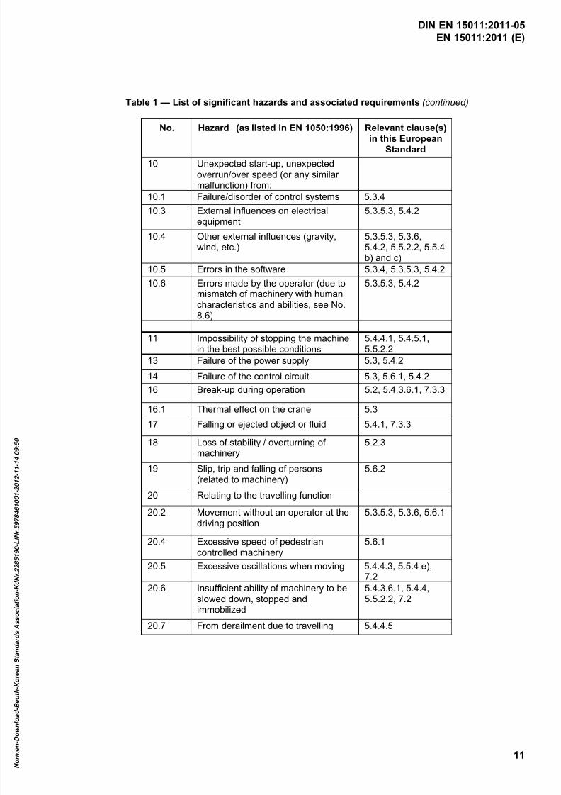
Table 1 — List of significant hazards and associated requirements (continued)
No. Hazard (as listed in EN 1050:1996) Relevant clause(s)
in this EuropeanStandard
10 Unexpected start-up, unexpectedoverrun/over speed (or any similarmalfunction) from:
10.1 Failure/disorder of control systems 5.3.4
10.3 External influences on electricalequipment
5.3.5.3, 5.4.2
10.4 Other external influences (gravity,wind, etc.)
5.3.5.3, 5.3.6,5.4.2, 5.5.2.2, 5.5.4b) and c)
10.5 Errors in the software 5.3.4, 5.3.5.3, 5.4.2
10.6 Errors made by the operator (due tomismatch of machinery with humancharacteristics and abilities, see No.8.6)
5.3.5.3, 5.4.2
11 Impossibility of stopping the machinein the best possible conditions
5.4.4.1, 5.4.5.1,5.5.2.2
13 Failure of the power supply 5.3, 5.4.2
14 Failure of the control circuit 5.3, 5.6.1, 5.4.2
16 Break-up during operation 5.2, 5.4.3.6.1, 7.3.3
16.1 Thermal effect on the crane 5.3
17 Falling or ejected object or fluid 5.4.1, 7.3.3
18 Loss of stability / overturning ofmachinery
5.2.3
19 Slip, trip and falling of persons(related to machinery)
5.6.2
20 Relating to the travelling function
20.2 Movement without an operator at thedriving position
5.3.5.3, 5.3.6, 5.6.1
20.4 Excessive speed of pedestrian
controlled machinery
5.6.1
20.5 Excessive oscillations when moving 5.4.4.3, 5.5.4 e),7.2
20.6 Insufficient ability of machinery to beslowed down, stopped andimmobilized
5.4.3.6.1, 5.4.4,5.5.2.2, 7.2
20.7 From derailment due to travelling 5.4.4.5
DIN EN 15011:2011-05
7/25/2019 DIN en 15011-2011 - Cranes - Bridge and Gantry Cranes
http://slidepdf.com/reader/full/din-en-15011-2011-cranes-bridge-and-gantry-cranes 14/95
EN 15011:2011 (E)
12
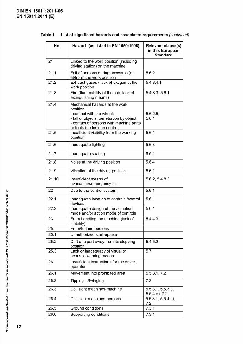
Table 1 — List of significant hazards and associated requirements (continued)
No. Hazard (as listed in EN 1050:1996) Relevant clause(s)in this European
Standard
21 Linked to the work position (includingdriving station) on the machine
21.1 Fall of persons during access to (orat/from) the work position
5.6.2
21.2 Exhaust gases / lack of oxygen at thework position
5.4.8.4.1
21.3 Fire (flammability of the cab, lack ofextinguishing means)
5.4.8.3, 5.6.1
21.4 Mechanical hazards at the workposition- contact with the wheels
- fall of objects, penetration by object- contact of persons with machine partsor tools (pedestrian control)
5.6.2.5,
5.6.1
21.5 Insufficient visibility from the workingposition
5.6.1
21.6 Inadequate lighting 5.6.3
21.7 Inadequate seating 5.6.1
21.8 Noise at the driving position 5.6.4
21.9 Vibration at the driving position 5.6.1
21.10 Insufficient means ofevacuation/emergency exit 5.6.2, 5.4.8.3
22 Due to the control system 5.6.1
22.1 Inadequate location of controls /controldevices
5.6.1
22.2 Inadequate design of the actuationmode and/or action mode of controls
5.6.1
23 From handling the machine (lack ofstability)
5.4.4.3
25 From/to third persons
25.1 Unauthorized start-up/use
25.2 Drift of a part away from its stoppingposition
5.4.5.2
25.3 Lack or inadequacy of visual oracoustic warning means
5.7
26 Insufficient instructions for the driver /operator
26.1 Movement into prohibited area 5.5.3.1, 7.2
26.2 Tipping - Swinging 7.2
26.3 Collision: machines-machine 5.5.3.1, 5.5.3.3,5.5.4 e), 7.2
26.4 Collision: machines-persons 5.5.3.1, 5.5.4 e),7.2
26.5 Ground conditions 7.3.1
26.6 Supporting conditions 7.3.1
DIN EN 15011:2011-05

7/25/2019 DIN en 15011-2011 - Cranes - Bridge and Gantry Cranes
http://slidepdf.com/reader/full/din-en-15011-2011-cranes-bridge-and-gantry-cranes 15/95
EN 15011:2011 (E)
13
Table 1 — List of significant hazards and associated requirements (continued)
No. Hazard (as listed in EN 1050:1996) Relevant clause(s)
in this EuropeanStandard
27 Mechanical hazards and events
27.1 from load falls, collision, machine tippingcaused by:
27.1.1 lack of stability 5.2.3, 5.4.8.5
27.1.2 Uncontrolled loading - overloading –overturning moment exceeded
5.2.1.5, 5.2.1.6,5.4.3.1 to 5.4.3.4,5.4.8.5, 5.5.1,5.5.2.1, 5.5.4 a)
27.1.3 Uncontrolled amplitude of movements 5.5.3.3, 7.2
27.1.4 Unexpected/unintended movement ofloads
5.3.4, 5.4.1, 5.4.2,5.4.3.1, 5.6, 7.2
27.1.5 Inadequate holding devices / accessories 5.4.1, 7.2
27.1.6 Collision of more than one machine 5.5.3.1, 5.5.3.3
27.1.7 Two-block of hook to hoist 5.4.3.1, 5.5.3.2
27.2 From access of persons to load support 7.2
27.3 From derailment 5.4.4.5, 5.4.4.6
27.4 From insufficient mechanical strength ofpartsLoss of mechanical strength, or
inadequate mechanical strength
5.2, 5.4.3, 5.4.5.3,5.4.6, 5.4.7, 7.3.3
27.5 From inadequate design of pulleys, drums 5.2, 5.4.1, 5.4.3.1
27.6 From inadequate selection/ integration intothe machine of chains, ropes, liftingaccessories
5.2, 5.4.1, 5.4.3.1,5.4.3.6.2, 7.2
27.7 From lowering of the load byfriction brake
5.4.1
27.8 From abnormal conditions of assembly /testing / use / maintenance
5.4.3.6.3, 5.5.4 d)
27.9 Load-person interference (impact by load) 5.6.1, 5.7, 7.2, 7.3.1
28 Electrical hazard
28.1 from lightning 7.3.3
29 Hazards generated by neglectingergonomic principles
29.1 insufficient visibility from the drivingposition
5.6.1, 5.6.3
DIN EN 15011:2011-05

7/25/2019 DIN en 15011-2011 - Cranes - Bridge and Gantry Cranes
http://slidepdf.com/reader/full/din-en-15011-2011-cranes-bridge-and-gantry-cranes 16/95
EN 15011:2011 (E)
14
5 Safety requirements and/or protective measures
5.1 General
Bridge and gantry cranes shall comply with the safety requirements and/or protective measures of Clause 5.In addition, these cranes shall be designed according to the principles of EN ISO 12100-2 for relevant but notsignificant hazards, which are not dealt with by this European Standard.
Bridge and gantry cranes shall be in accordance with the following standards as amended by this EuropeanStandard:
EN 13001-1, Cranes — General design — Part 1: General principles and requirements;
EN 13001-2, Cranes — General design — Part 2: Load effects;
prEN 13001-3-1, Cranes — General Design — Part 3-1: Limit States and proof competence of steel
structures;
CEN/TS 13001-3-2, Cranes — General design — Part 3-2: Limit states and proof of competence of wireropes in reeving systems;
EN 13135-1, Cranes — Equipment — Part 1: Electrotechnical equipment ;
EN 13135-2, Cranes — Equipment — Part 2: Non-electrotechnical equipment ;
EN 13155, Cranes — Safety — Non-fixed load lifting attachments;
EN 13157, Cranes — Safety — Hand powered cranes;
EN 13557, Cranes — Controls and control stations;
EN 12077-2, Cranes safety — Requirements for health and safety — Part 2: Limiting and indicatingdevices;
EN 13586, Cranes — Access;
EN 12644-1, Cranes — Information for use and testing — Part 1: Instructions;
EN 12644-2, Cranes — Information for use and testing — Part 2: Marking ;
EN 60204-32, Safety of machinery — Electrical equipment of machines — Part 32: Requirements for
hoisting machines (IEC 60204-32:2008).
The requirements of this European Standard are not applicable to power driven hoist units, designed inaccordance with EN 14492-2, and incorporated in a bridge and gantry cranes. These hoist units shall beselected accordance to the principles depicted within A.4.
5.2 Requirements for strength and stability
5.2.1 Load actions
5.2.1.1 Selection of service conditions
The service conditions that are selected and used as the basis of design, in accordance with EN 13001-1 andEN 13001-2, shall be specified in the technical file of the crane.
DIN EN 15011:2011-05
7/25/2019 DIN en 15011-2011 - Cranes - Bridge and Gantry Cranes
http://slidepdf.com/reader/full/din-en-15011-2011-cranes-bridge-and-gantry-cranes 17/95
EN 15011:2011 (E)
15
For cranes located outdoors, the recurrence period according to EN 13001-2 for out of service wind shall be notless than:
25 years for cranes located in coastal areas;
10 years for cranes located inland;
5 years for indoor cranes which may occasionally work and/or be parked outdoors.
NOTE Guidance for specifying the operation duty is given in Annex A. For information needed for the derivation ofclassification parameters see also ISO 9374-5.
5.2.1.2 Selection of loads and load combinations
The basic load combinations for the load calculation shall be selected in accordance withEN 13001-2:2004+A3:2009, Table 10.
Where cranes work in atmospheres contaminated by process debris, such material accumulations deposited
upon the upper surfaces of the crane shall be taken into account in the dead load computation.
5.2.1.3 Determination of dynamic factors
5.2.1.3.1 Hoisting and gravity effects acting on the mass of the crane
The masses of the crane shall be multiplied with factor φ1 = 1 + δ when calculating the stresses in loadcombinations in accordance with EN 13001-2.
For cranes belonging to the mass distribution class MDC1, δ = 0,1 and φ1 = 1,10.
For cranes belonging to the mass distribution class MDC2, which have both favourable and unfavourable
effects, the dynamic factor shall be taken as φ1 = 1,10 for unfavourable effects and φ1 = 0,90 for favourableeffects.
5.2.1.3.2 Determination of factor φφφφ2
5.2.1.3.2.1 General principles
The hoist load shall be multiplied by factor φ2 that represents the additional dynamic force applied on thecrane, when the weight of a grounded load is transferred on the hoisting medium (ropes or chains).
When assuming the most extreme conditions, the hoisting medium is slack whilst the hoist mechanismreaches its maximum hoisting speed. In this condition the dynamic additional force is directly proportional to
the hoisting speed, with a coefficient that depends upon the stiffness properties and mass distribution of thecrane ( β 2 in EN 13001-2). A calculation model for the determination of the dynamic rope force history at the
hoisting event, and resulting theoretical factor φ2t, is presented in Annex C.
In physical crane operation there are other factors that influence the actual dynamic effect, such as controlsystems, dampening and flexibility of other than main components (e.g. hoist slings, other lifting devices, load
itself, crane foundation). These dependencies and determination of factor φ2 are represented by hoistingclasses in EN 13001-2.
When hoisting class is used it shall be selected according to 5.2.1.3.2.3.
The hoisting speed used for the determination of the dynamic coefficient shall reflect the actual use and
possible exceptional events of the crane in a realistic way. Two events shall be considered as follows:
crane in normal use where hoisting commences at a mechanism controlled speed from a slack ropecondition – cases A and B as per EN 13001-2;
DIN EN 15011:2011-05
7/25/2019 DIN en 15011-2011 - Cranes - Bridge and Gantry Cranes
http://slidepdf.com/reader/full/din-en-15011-2011-cranes-bridge-and-gantry-cranes 18/95
EN 15011:2011 (E)
16
exceptional case where hoisting commences at mechanism maximum speed from slack rope condition –case C as per EN 13001-2.
Guidance on selection of hoisting speeds is given in 5.2.1.3.2.4.
5.2.1.3.2.2 Calculation of the theoretical factor φφφφ2t
The theoretical dynamic factor φ2t is used for the determination of the hoisting class as defined in EN 13001-2.
It shall be estimated in one of the following ways:
— make a complete dynamic simulation taking into account the elastic, inertial and dampeningproperties. The maximum force in the hoisting medium during time of the first 3 s represents the hoist
load multiplied by factor φ2t;
— where applicable, the rope force history φh(t) may be calculated in accordance with Annex C.
φ2t = max{φh(t); t < 3 s}. (A similar simulation can be used for a crane with a chain hoist.);
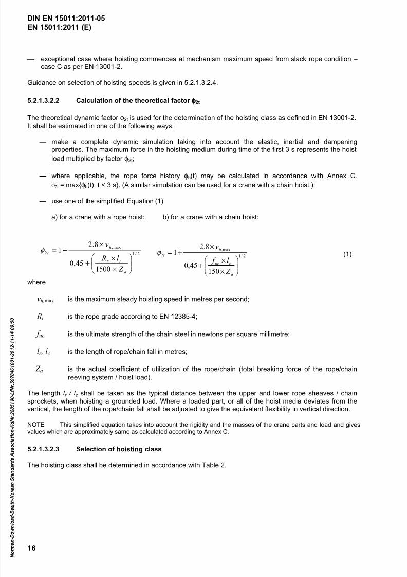
— use one of the simplified Equation (1).
a) for a crane with a rope hoist: b) for a crane with a chain hoist:
where
vh,max is the maximum steady hoisting speed in metres per second;
Rr is the rope grade according to EN 12385-4;
f uc is the ultimate strength of the chain steel in newtons per square millimetre;
l r , l c is the length of rope/chain fall in metres;
Z a is the actual coefficient of utilization of the rope/chain (total breaking force of the rope/chain
reeving system / hoist load).
The length l r / l c shall be taken as the typical distance between the upper and lower rope sheaves / chain
sprockets, when hoisting a grounded load. Where a loaded part, or all of the hoist media deviates from thevertical, the length of the rope/chain fall shall be adjusted to give the equivalent flexibility in vertical direction.
NOTE This simplified equation takes into account the rigidity and the masses of the crane parts and load and givesvalues which are approximately same as calculated according to Annex C.
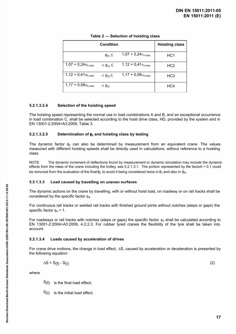
5.2.1.3.2.3 Selection of hoisting class
The hoisting class shall be determined in accordance with Table 2.
2/1
max,
2
15045,0
8.21
×
×+
×+=
a
cuc
h
t
Z
l f
vφ 2/1
max,
2
150045,0
8.21
×
×+
×+=
a
r r
h
t
Z
l R
vφ
(1)
DIN EN 15011:2011-05
7/25/2019 DIN en 15011-2011 - Cranes - Bridge and Gantry Cranes
http://slidepdf.com/reader/full/din-en-15011-2011-cranes-bridge-and-gantry-cranes 19/95
EN 15011:2011 (E)
17
Table 2 — Selection of hoisting class
Condition Hoisting class
φ2t ≤ 1,07 + 0,24vh,max HC1
1,07 + 0,24v h,max < φ2t ≤ 1,12 + 0,41vh,max HC2
1,12 + 0,41v h,max < φ2t ≤ 1,17 + 0,58vh,max HC3
1,17 + 0,58v h,max < φ2t HC4
5.2.1.3.2.4 Selection of the hoisting speed
The hoisting speed representing the normal use in load combinations A and B, and an exceptional occurrencein load combination C, shall be selected according to the hoist drive class, HD, provided by the system and inEN 13001-2:2004+A3:2009, Table 3.
5.2.1.3.2.5 Determination of φφφφ2 and hoisting class by testing
The dynamic factor φ2 can also be determined by measurement from an equivalent crane. The valuesmeasured with different hoisting speeds shall be directly used in calculations, without reference to a hoistingclass.
NOTE The dynamic increment of deflections found by measurement or dynamic simulation may include the dynamic
effects from the mass of the crane including the trolley, see 5.2.1.3.1. The portion represented by the factor δ = 0,1 could
be removed from the evaluation of the final φ2 to avoid it being considered twice in φ1 and also in φ2.
5.2.1.3.3 Load caused by travelling on uneven surfaces
The dynamic actions on the crane by travelling, with or without hoist load, on roadway or on rail tracks shall be
considered by the specific factor φ4.
For continuous rail tracks or welded rail tracks with finished ground joints without notches (steps or gaps) the
specific factor φ4 = 1.
For roadways or rail tracks with notches (steps or gaps) the specific factor φ4 shall be calculated according toEN 13001-2:2004+A3:2009, 4.2.2.3. For rubber tyred cranes the flexibility of the tyre shall be taken intoaccount.
5.2.1.3.4 Loads caused by acceleration of drives
For crane drive motions, the change in load effect, ∆S, caused by acceleration or deceleration is presented bythe following equation:
∆S = S(f) - S(i) (2)
where
S(f) is the final load effect;
S(i) is the initial load effect.
DIN EN 15011:2011-05
7/25/2019 DIN en 15011-2011 - Cranes - Bridge and Gantry Cranes
http://slidepdf.com/reader/full/din-en-15011-2011-cranes-bridge-and-gantry-cranes 20/95
EN 15011:2011 (E)
18
NOTE 1 The change in load effects, ∆S, is caused by the change of drive force, ∆F, given by the equation:
∆F = F(f) - F(i)
where
F(f) is the final drive force; and
F(i) is the initial drive force.
Loads induced in a crane by acceleration or deceleration caused by drive forces may be calculated using rigidbody kinetic models. The load effect S shall be applied to the components exposed to the drive forces andwhere applicable to the crane and the hoist load as well. As a rigid body analysis does not directly reflect
elastic effects, the load effect S shall be calculated by using an amplification factor φ5 defined inEN 13001-2:2004+A3:2009, 4.2.2.4 as follows:
S = S(i) + φp ⋅ φ5 ⋅ a ⋅ m (3)
where
S(i) is the initial load effect caused by F(i);
φ5 is the amplification factor;
φp is the factor for effect of sequential positioning movements;
a is the acceleration or deceleration value;
m is the mass for which a applies.
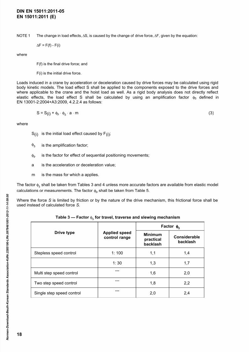
The factor φ5 shall be taken from Tables 3 and 4 unless more accurate factors are available from elastic modelcalculations or measurements. The factor φp shall be taken from Table 5.
Where the force S is limited by friction or by the nature of the drive mechanism, this frictional force shall beused instead of calculated force S.
Table 3 — Factor φ5 for travel, traverse and slewing mechanism
Drive type Applied speedcontrol range
Factor φφφφ5
Minimumpractical
backlash
Considerablebacklash
Stepless speed control 1: 100 1,1 1,4
1: 30 1,3 1,7
Multi step speed control---
1,6 2,0
Two step speed control---
1,8 2,2
Single step speed control---
2,0 2,4
DIN EN 15011:2011-05
7/25/2019 DIN en 15011-2011 - Cranes - Bridge and Gantry Cranes
http://slidepdf.com/reader/full/din-en-15011-2011-cranes-bridge-and-gantry-cranes 21/95
EN 15011:2011 (E)
19
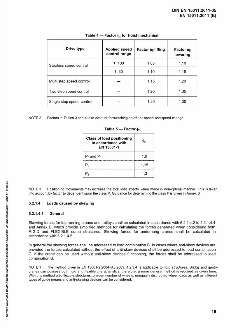
Table 4 — Factor φ5 for hoist mechanism
Drive type Applied speedcontrol range
Factor φφφφ5 lifting Factor φφφφ5
lowering
Stepless speed control1: 100 1,05 1,10
1: 30 1,10 1,15
Multi step speed control --- 1,15 1,20
Two step speed control --- 1,20 1,35
Single step speed control --- 1,20 1,30
NOTE 2 Factors in Tables 3 and 4 take account for switching on/off the speed and speed change.
Table 5 — Factor φφφφP
Class of load positioningin accordance with
EN 13001-1
φP
P0 and P1 1,0
P2 1,15
P3 1,3
NOTE 3 Positioning movements may increase the total load effects, when made in non-optimal manner. This is taken
into account by factor φP dependent upon the class P. Guidance for determining the class P is given in Annex B.
5.2.1.4 Loads caused by skewing
5.2.1.4.1 General
Skewing forces for top running cranes and trolleys shall be calculated in accordance with 5.2.1.4.2 to 5.2.1.4.4and Annex D, which provide simplified methods for calculating the forces generated when considering bothRIGID and FLEXIBLE crane structures. Skewing forces for underhung cranes shall be calculated inaccordance with 5.2.1.4.5.
In general the skewing forces shall be addressed to load combination B. In cases where anti-skew devices areprovided the forces calculated without the effect of anti-skew devices shall be addressed to load combinationC. If the crane can be used without anti-skew devices functioning, the forces shall be addressed to loadcombination B.
NOTE 1 The method given in EN 13001-2:2004+A3:2009, 4.2.3.4 is applicable to rigid structures. Bridge and gantrycranes can possess both rigid and flexible characteristics; therefore, a more general method is required as given here.With this method also flexible structures, uneven number of wheels, unequally distributed wheel loads as well as differenttypes of guide means and anti-skewing devices can be considered.
DIN EN 15011:2011-05

7/25/2019 DIN en 15011-2011 - Cranes - Bridge and Gantry Cranes
http://slidepdf.com/reader/full/din-en-15011-2011-cranes-bridge-and-gantry-cranes 22/95
EN 15011:2011 (E)
20
NOTE 2 Forces arising from skewing are generated when the resultant direction of rolling movement of the travelling
crane no longer coincides with the direction of the runway rail, and when the front positive guiding means come into
contact with the rail. This is caused by tolerances and inaccuracies, which arise in the manufacture of the crane (bores of
track wheels) and that of the runway's rail (bends, kinks). The values and distribution of these forces depend chiefly upon
the clearances between the runway rail and the wheel flanges or guide rollers and the latter's location, also on the number,
arrangement, bearing arrangement and rotational speed synchronisation of the track wheels and structural flexibility.
NOTE 3 The use of anti-skew devices with travel motions reduces the guiding forces between the rail and guidingmeans. It also reduces the lateral slip forces of the wheels, but some lateral slip remains due to wheel alignmenttolerances and lateral deformations of structures, which effect should be considered.
5.2.1.4.2 Skew angle
The skew angle shall be calculated as follows:
W bW b W b
S g
bh
S g
bh
Figure 1 — Parameters of skew angle
The total skew angle to be considered in design is
t w g
α α α α ++=
where
α is the skew angle to be considered in design;
α g is the skew component sg / wb;
α w is the component due to wear - rail and wheel flange/guide roller;
α t is the component due to alignment tolerances of rail/wheel.
The values for skew angles shall be determined according to Table 6.
DIN EN 15011:2011-05
7/25/2019 DIN en 15011-2011 - Cranes - Bridge and Gantry Cranes
http://slidepdf.com/reader/full/din-en-15011-2011-cranes-bridge-and-gantry-cranes 23/95
EN 15011:2011 (E)
21
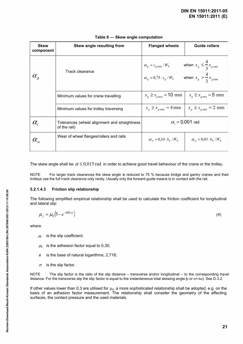
Table 6 — Skew angle computation
Skewcomponent
Skew angle resulting from Flanged wheels Guide rollers
g α
Track clearance
b g g W s /min=α when min3
4 g g s s ≤
b g g W s /75,0 ⋅=α when min3
4 g g s s >
Minimum values for crane travelling mm10=≥ min g g s s mm5=≥ min g g s s
Minimum values for trolley traversing mm4min =≥ g g s s mm2min =≥ g g s s
t α Tolerances (wheel alignment and straightnessof the rail)
0010 ,t =α rad
wα
Wear of wheel flanges/rollers and railsbhw W b /10,0 ⋅=α bhw W b /03,0 ⋅=α
The skew angle shall be rad015,0≤α in order to achieve good travel behaviour of the crane or the trolley.
NOTE For larger track clearances the skew angle is reduced to 75 % because bridge and gantry cranes and their
trolleys use the full track clearance only rarely. Usually only the forward guide means is in contact with the rail.
5.2.1.4.3 Friction slip relationship
The following simplified empirical relationship shall be used to calculate the friction coefficient for longitudinaland lateral slip:
( )σ µ µ 250
0 1 −−= e f (4)
where
µ f is the slip coefficient;
µ 0 is the adhesion factor equal to 0,30;
e is the base of natural logarithms, 2,718;
σ is the slip factor.
NOTE The slip factor is the ratio of the slip distance – transverse and/or longitudinal – to the corresponding travel
distance. For the transverse slip the slip factor is equal to the instantaneous total skewing angle (α or α+∆α). See D.3.2.
If other values lower than 0,3 are utilised for µ0, a more sophisticated relationship shall be adopted, e.g. on thebasis of an adhesion factor measurement. The relationship shall consider the geometry of the affectingsurfaces, the contact pressure and the used materials.
DIN EN 15011:2011-05

7/25/2019 DIN en 15011-2011 - Cranes - Bridge and Gantry Cranes
http://slidepdf.com/reader/full/din-en-15011-2011-cranes-bridge-and-gantry-cranes 24/95
EN 15011:2011 (E)
22
5.2.1.4.4 Selection of calculation methods
Either of two simplified calculation methods shall be used: either a RIGID or FLEXIBLE method. The RIGIDmethod assumes the structures of the crane and the runway to be rigid. The FLEXIBLE method assumes thestructure to be flexible. In cases of doubt the FLEXIBLE method should be utilised.
Calculation models to be adopted relative to the crane/trolley structural configuration are listed within Table 7.
DIN EN 15011:2011-05
7/25/2019 DIN en 15011-2011 - Cranes - Bridge and Gantry Cranes
http://slidepdf.com/reader/full/din-en-15011-2011-cranes-bridge-and-gantry-cranes 25/95
EN 15011:2011 (E)
23
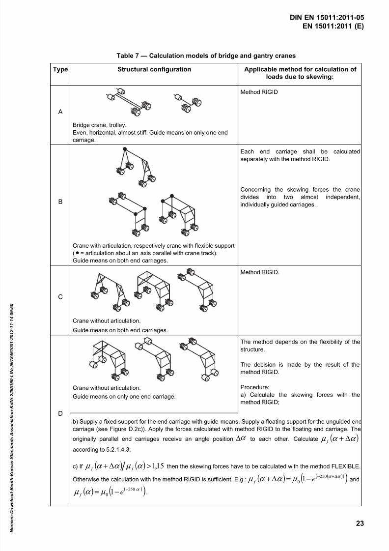
Table 7 — Calculation models of bridge and gantry cranes
Type Structural configuration Applicable method for calculation ofloads due to skewing:
A
Bridge crane, trolley.
Even, horizontal, almost stiff. Guide means on only one end
carriage.
Method RIGID
B
Crane with articulation, respectively crane with flexible support
( • = articulation about an axis parallel with crane track).
Guide means on both end carriages.
Each end carriage shall be calculated
separately with the method RIGID.
Concerning the skewing forces the cranedivides into two almost independent,
individually guided carriages.
C
Crane without articulation.
Guide means on both end carriages.
Method RIGID.
D
Crane without articulation.
Guide means on only one end carriage.
The method depends on the flexibility of the
structure.
The decision is made by the result of the
method RIGID.
Procedure:
a) Calculate the skewing forces with the
method RIGID;
b) Supply a fixed support for the end carriage with guide means. Supply a floating support for the unguided end
carriage (see Figure D.2c)). Apply the forces calculated with method RIGID to the floating end carriage. The
originally parallel end carriages receive an angle position ∆ to each other. Calculate ( )α α µ ∆+ f
according to 5.2.1.4.3;
c) If ( ) ( ) 15,1>∆+ α µ α α µ f f then the skewing forces have to be calculated with the method FLEXIBLE.
Otherwise the calculation with the method RIGID is sufficient. E.g.: ( ) ( )( )
( )α α
µ α α µ
∆+−
−=∆+
250
0 1 e f and
( ) ( )( )α µ α µ 250
0 1 −−= e f .
DIN EN 15011:2011-05

7/25/2019 DIN en 15011-2011 - Cranes - Bridge and Gantry Cranes
http://slidepdf.com/reader/full/din-en-15011-2011-cranes-bridge-and-gantry-cranes 26/95
EN 15011:2011 (E)
24
5.2.1.4.5 Skewing forces for underhung cranes
The skewing forces of the underhung cranes, having rigid structure and running on the bottom flanges ofrigidly fixed runway beams, shall be calculated with the same principles as the top running cranes. See D.2.
However, the guiding force Y F may be divided on two wheel flanges of a leading bogie. The minor lateral
forces of the trailing bogies may be ignored. Figure 2 represents an example of the structures and onepossible set of the most critical skewing force combinations.
For configurations where either a runway beam (or both of them) or the bogies on one of the runways, can
float laterally, the lateral forces Y 1 and Y 2 are balanced by separate guiding forces Y F on both leading bogies.
In these cases the guiding forces ½Y F shall be taken conventionally as 20 % of the maximum static vertical
force Z of the wheel. Y 1 and Y 2 , frictional forces are then 10 % of the vertical wheel force of each wheel. Theguiding forces, YF, and frictional forces, Y, balance each other separately on both runways, forming internalforce systems within the bogies (element b) in Figure 2), and also local internal force systems within thebottom runway flanges. These forces balanced locally do not impose external forces on the crane structure.
Key1 bottom flange and cut web of runway beam No. 12 bottom flange and cut web of runway beam No. 23 crane girder; end carriage beams under the runways not shown4 hoist trolley with load5 4-wheel bogies at each corner of the crane Y 1 transverse frictional skewing forces applied between the wheels and the top surface of the bottom flange
of the runway 1
Y 2 transverse frictional skewing forces applied between the wheels and the top surface of the bottom flange
of the runway 2
Y F guiding force applied to the wheel flanges of the guiding bogie
F y minimum transverse forces to be also considered in bogie design as shown in element b)Z maximum dynamic wheel force in vertical direction
Figure 2 — Skewing forces of underhung crane
DIN EN 15011:2011-05

7/25/2019 DIN en 15011-2011 - Cranes - Bridge and Gantry Cranes
http://slidepdf.com/reader/full/din-en-15011-2011-cranes-bridge-and-gantry-cranes 27/95
EN 15011:2011 (E)
25
Besides the skewing, the lateral forces on the bogies of the underhung cranes are created also byacceleration of the crane loaded asymmetrically and by acceleration of the hoist trolley and load. These forcesshall be considered according to 5.2.1.3.4.
5.2.1.5 Overload condition
5.2.1.5.1 Cranes with direct acting lifting force limiter
The maximum force, F max.L, which is applied to the crane when the direct acting lifting force limiter operates,shall be calculated as follows:
g m F H DAL L ⋅⋅= φ max (5)
where
F max.L is the maximum force in newtons;
φ DAL is the force-limit factor for direct acting lifting force limiters [-];
mH is the mass of the hoist load in kilograms;
g is the gravity constant 9,81 m/s2.
For hydraulic systems, the factor φ DAL shall be less than or equal to 1,4, with friction torque limiters orpneumatic systems this factor shall be less than, or equal to 1,6.
The force F max.L shall be assigned to the load combination C1 of EN 13001-2:2004+A3:2009, Table 10, and asa load to line 13 in the stability combination C3 of Table 11 in the same standard.
5.2.1.5.2 Cranes with indirect acting lifting force limiter
The maximum force, F max.L , which is applied to the crane, resulting from the operation of the indirect actinglifting force limiter in an overload, stall load and if relevant, in a snag load case, shall be calculated as follows:
g m F H IAL L ⋅⋅= φ max (6)
where
F max.L is the maximum force in newtons;
φ IAL is the load factor for maximum force [-];
mH is the mass of the hoist load in kilograms;
g is the gravity constant 9,81 m/s2.
The F max.L represents the final load in the hoist system after the triggering has operated and the hoist motion is
brought to rest. It shall be calculated with due consideration to stiffness of the hoist mechanism and structuresas a whole, properties of stall load protection system, properties of the hoist drive system and functioning ofthe indirect acting limiter, see 5.5.1.2. Guidance of a calculation method is given Annex E.
The force F max.L shall be assigned to the load combination C1 of EN 13001-2:2004+A3:2009, Table 10, and as
a load to line 13 in the stability combination C3 of Table 11 in the same standard.
5.2.1.6 Test loads
The overload test loads to be taken into account in calculation shall be in accordance with 6.3.2.
DIN EN 15011:2011-05
7/25/2019 DIN en 15011-2011 - Cranes - Bridge and Gantry Cranes
http://slidepdf.com/reader/full/din-en-15011-2011-cranes-bridge-and-gantry-cranes 28/95
EN 15011:2011 (E)
26
5.2.1.7 Design basis for multi point lifting in cases where the lifting forces are not equalized
For cranes, which are equipped with two or more lifting points for lifting a single load, e.g. container liftingframe, the loading on an individual lifting point will depend upon the position of the load centre of gravity withrespect to the lifting points. Location of centres of gravities with relevant loads shall be specified in the
technical file and in the operating instructions.
In force calculations both the case of a mid-air load suspension and that of a load being grounded, possibly inan inclined position or on an inclined plane, shall be considered. The forces from the latter case (inclinedgrounding) shall be addressed to one of the load combinations A, B or C based upon its frequency ofoccurrence.
The proof of static strength for the lifting points shall be based upon the maximum force resulting from thehoist load and maximum load eccentricity. The maximum force possible in each lifting point shall beconsidered as a regular load in all relevant load combinations A, B and C according to EN 13001-2. Dueconsideration shall be given to the effect of horizontal load actions on the forces in the lifting points.
The proof of fatigue strength shall take into account the whole range of centre of gravity locations, the
frequency of occurrence of these locations and distribution of load values. The resulting fatigue loading shallbe expressed by a series of loads on the lifting points and their respective frequencies of occurrence.Horizontal load actions and inclined grounding shall be considered in case they appear in load combination A.
5.2.1.8 Conditions of use of permissible stress method and limit state method
Selection of allowable stress method or limit state method shall be made in accordance with EN 13001-1 andEN 13001-2.
5.2.2 Limit states and proof of competence
5.2.2.1 Limit states and proof of competence of structural members
The limit states and proof of competence of structural members and connections shall be determined inaccordance with prEN 13001-3-1.
5.2.2.2 Limit states of mechanical components
Proof of competence of ropes in rope drives shall be in accordance with CEN/TS 13001-3-2.
NOTE A European Standard for the selection of rail wheels is under preparation. While the appropriate standard isnot available, the rail wheels and rails may be selected in accordance with ISO 16881-1. Other methods that are based onexperimental knowledge on the wear of the used materials and which give comparable life of the wheels can be used.
For other components the load effects and required life (number of cycles) shall be derived from the service
and load conditions specified in 5.2.1 and they shall not exceed the limit states specified by the componentmanufacturer.
5.2.2.3 Local stresses from wheel loads
The stresses of a supporting structure transmitted from local wheel loads shall be calculated and allocated to
the load combinations A, B and C (EN 13001-2:2004+A3:2009, Table 10) taking into account the relevant φi factors.
Travel wheels generally transmit vertical and tangential wheel loads. The effects of these wheel loads on allfurther load transmitting elements of the supporting structure shall be proven for local stresses.
Distribution of wheel loads of a crane or a trolley shall not be considered equalized unless equalizing isensured by appropriate arrangements (e.g. pinned bogies, balancers, flexibility of structures).
DIN EN 15011:2011-05
7/25/2019 DIN en 15011-2011 - Cranes - Bridge and Gantry Cranes
http://slidepdf.com/reader/full/din-en-15011-2011-cranes-bridge-and-gantry-cranes 29/95
EN 15011:2011 (E)
27
Stresses resulting from vertical wheel loads in the web under the rail shall be calculated in accordance withEN 1993-6:2007, 5.7.1 and 5.7.2.
NOTE 1 When passing over to cantilevers the local stresses will be double when l eff is only half length.
NOTE 2 Annex F presents one permissible method to determine the stresses in the case of cranes with the trolleytravelling on the lower flange of the girder.
The local stress due to the wheel load shall be combined with the global normal and shear stresses for thedetermination of the equivalent stress intensity in accordance with the principles given in EN 13001-2.
For fatigue assessment, the total number of rail wheel overruns at the mostly loaded position shall beestimated.
When selecting the fatigue strength specific resistant factor γ mf for fatigue (see prEN 13001-3-1), the weld jointof flange/web may be regarded as a fail-safe component.
5.2.2.4 Proof of strength of lifting points
Lifting points (holes and lugs) used for erection and maintenance purposes shall be calculated by either:
using theory of plasticity with a minimum factor of 4 and welds to structures with a minimum factor of 5against ultimate strength of steel. To justify the use of this theory, the percentage elongation after fractureof the materials shall be at least 15 %; or
using the theory of elasticity.
5.2.2.5 Elastic deformation
The elastic deformations of the crane structure shall not have a detrimental influence on the function of the
crane.
NOTE Information and guide values for the specification of crane girders are given in ISO 22986.
5.2.2.6 Vibration frequencies of crane girders
Recommended natural frequencies of structural vibrations are given in ISO 22986. Where frequencies arelower, consideration shall be given to the effect of additional fatigue on the structure and to load control.Consideration shall also be given to minimize the amplitude and duration of vibrations e.g. by using steplesscontrols.
NOTE See also 5.6.1 concerning cabins.
5.2.3 Stability
5.2.3.1 General requirements
A crane is considered to be stable, when the overturning moment calculated with specified loads and factorsis smaller than the stabilising moment about any tipping axis.
The partial safety factors for the proof of stability of the crane shall be taken from EN 13001-2.
5.2.3.2 Gantry crane configurations
A basic crane configuration assumes a fixed legged crane standing on four or more corners.
For other crane configurations an additional risk coefficient γ n shall be applied for all non-favourable loads ofEN 13001-2:2004+A3:2009, Table 11 based upon the leg configuration of a crane as follows:
DIN EN 15011:2011-05
7/25/2019 DIN en 15011-2011 - Cranes - Bridge and Gantry Cranes
http://slidepdf.com/reader/full/din-en-15011-2011-cranes-bridge-and-gantry-cranes 30/95
EN 15011:2011 (E)
28
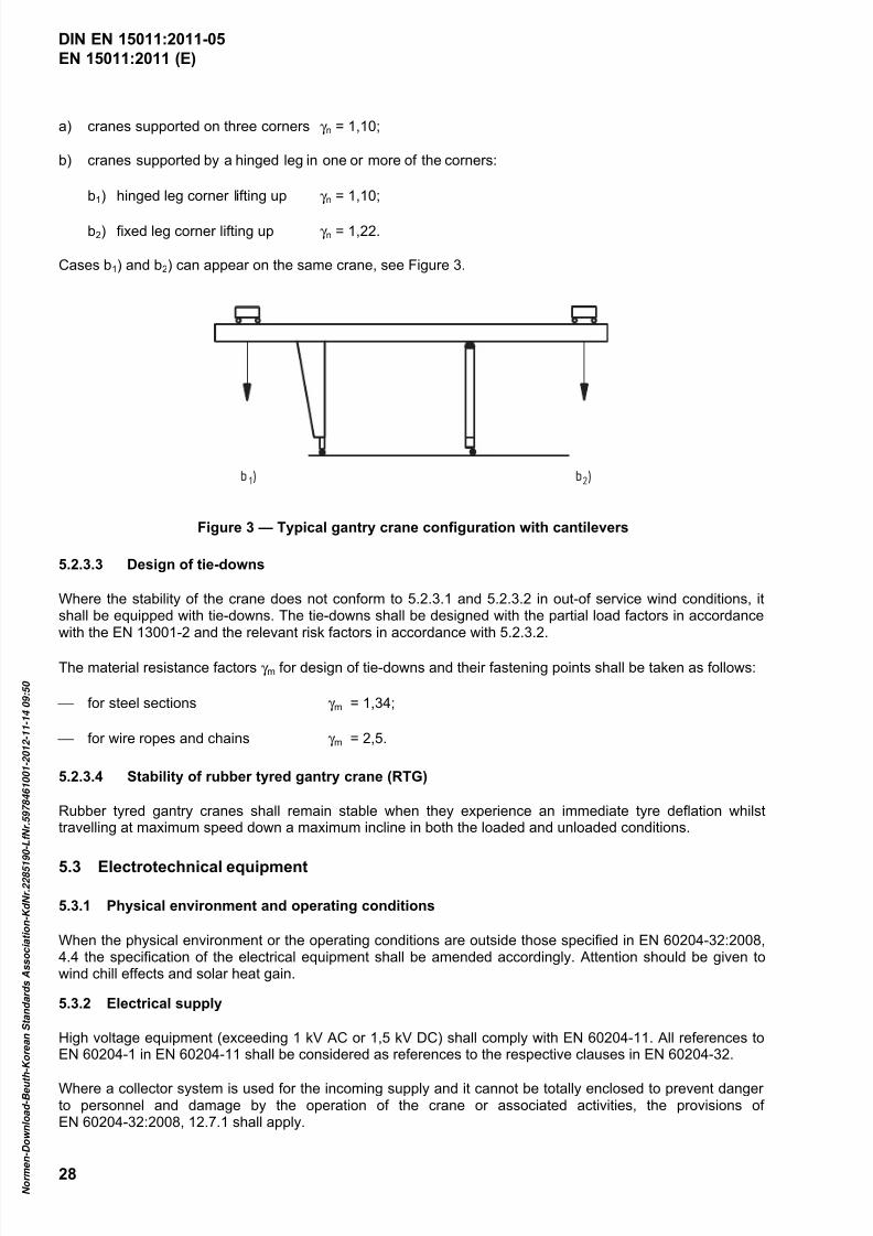
a) cranes supported on three corners γ n = 1,10;
b) cranes supported by a hinged leg in one or more of the corners:
b1) hinged leg corner lifting up γ n = 1,10;
b2) fixed leg corner lifting up γ n = 1,22.
Cases b1) and b2) can appear on the same crane, see Figure 3.
b )1 b )2
Figure 3 — Typical gantry crane configuration with cantilevers
5.2.3.3 Design of tie-downs
Where the stability of the crane does not conform to 5.2.3.1 and 5.2.3.2 in out-of service wind conditions, itshall be equipped with tie-downs. The tie-downs shall be designed with the partial load factors in accordancewith the EN 13001-2 and the relevant risk factors in accordance with 5.2.3.2.
The material resistance factors γ m for design of tie-downs and their fastening points shall be taken as follows:
for steel sections γ m = 1,34;
for wire ropes and chains γ m = 2,5.
5.2.3.4 Stability of rubber tyred gantry crane (RTG)
Rubber tyred gantry cranes shall remain stable when they experience an immediate tyre deflation whilsttravelling at maximum speed down a maximum incline in both the loaded and unloaded conditions.
5.3 Electrotechnical equipment
5.3.1 Physical environment and operating conditions
When the physical environment or the operating conditions are outside those specified in EN 60204-32:2008,4.4 the specification of the electrical equipment shall be amended accordingly. Attention should be given towind chill effects and solar heat gain.
5.3.2 Electrical supply
High voltage equipment (exceeding 1 kV AC or 1,5 kV DC) shall comply with EN 60204-11. All references toEN 60204-1 in EN 60204-11 shall be considered as references to the respective clauses in EN 60204-32.
Where a collector system is used for the incoming supply and it cannot be totally enclosed to prevent dangerto personnel and damage by the operation of the crane or associated activities, the provisions ofEN 60204-32:2008, 12.7.1 shall apply.
DIN EN 15011:2011-05

7/25/2019 DIN en 15011-2011 - Cranes - Bridge and Gantry Cranes
http://slidepdf.com/reader/full/din-en-15011-2011-cranes-bridge-and-gantry-cranes 31/95
7/25/2019 DIN en 15011-2011 - Cranes - Bridge and Gantry Cranes
http://slidepdf.com/reader/full/din-en-15011-2011-cranes-bridge-and-gantry-cranes 32/95
EN 15011:2011 (E)
30
Hold to Run: White;
Reset: Blue;
Emergency Stop: Red (with yellow background);
The stop actuator of a cableless control station: Red;
Other functions: Yellow or grey.
The function to be activated shall be indicated on or near to the button.
5.3.5.3 Devices for emergency stop
The provisions specified in EN 60204-32 shall apply.
Devices shall also be provided in the following locations to stop the appropriate motions:
on the crane structure at ground level on both sides or at each corner of a cabin controlled gantry crane;
in the machinery room;
any other location based on risk assessment.
Emergency stop devices located at control stations shall be of the palm or mushroom-headed push-button self-latching type complying with the provisions of EN 60947-5-5. The type of emergency stop devices for otherlocations shall be selected so as to achieve easy identification and access to them, and to avoid unintentionalactuation.
Where the cableless control station is the only place of control on an overhead bridge crane, an emergency
stop actuator in addition to the stop button on the cableless control is not required, provided all the followingconditions apply:
it is ensured that a lost cableless control station cannot send any run command;
there are no operator access ways on the crane;
the crane runway has no access facilities.
5.3.6 Power driven motions
All power driven motions shall be power driven at all times.
NOTE Exempt is an emergency situation, when mechanical brakes may be manually released by skilled personnel, ifthe necessary provisions are available to stop the motion to prevent a hazardous situation occurring.
5.4 Non-electrotechnical equipment
5.4.1 General
The mechanical, hydraulic and pneumatic equipment shall meet the requirements of EN 13135-2 as amendedby this European Standard.
DIN EN 15011:2011-05
7/25/2019 DIN en 15011-2011 - Cranes - Bridge and Gantry Cranes
http://slidepdf.com/reader/full/din-en-15011-2011-cranes-bridge-and-gantry-cranes 33/95
EN 15011:2011 (E)
31
5.4.2 Braking systems
5.4.2.1 General
All power driven motions shall be under the control of a braking system at all times. The braking systems shall
be such that movements can be decelerated, the motions can be held and unintentional movements avoided.The systems shall be capable of bringing a fully loaded crane to rest from the highest speed it can attain.
5.4.2.2 Mechanical service brakes in power driven motions
Only power released brakes shall be used and they shall maintain their ability to stop the motion, at all times.
Brakes shall be protected from the ingress of substances within the environment, which are likely to have adetrimental effect on the performance of the brake.
NOTE Where electrical braking systems are used, the associated mechanical brake is only subjected to limited use.Special attention therefore may be needed to maintain the required mechanical braking torque, see 7.3.3.
Mechanical service brakes shall engage automatically in the following cases:
the control device returns to its neutral position;
the power supply to the brake is interrupted;
the emergency stop device is activated.
5.4.2.3 Brakes for hoisting movements
The brakes shall be designed to exert a restraining torque of at least 60 % greater than the maximum torquetransmitted to the brake from the maximum hoist load. In addition the hoist brake shall comply with
EN 13135-2:2004+A1:2010, 5.3.3.2.
Back-up braking, as defined in EN 13135-2, shall be initiated immediately, when a failure has been detected inthe service braking system or in the kinematic chain. In normal operating conditions and in the case ofemergency stops, it shall be applied with a delay that allows the service braking system to stop the hoistmotion, unless the repeated back-up braking function has been taken into account in the design. When back-up braking has been initiated by a system failure, the reset shall only be possible by skilled personnel.
5.4.3 Hoisting equipment
5.4.3.1 Selection of serial hoist units
Where a hoist unit in accordance with EN 14492-2 is used as a component in the crane, its selection shall bebased on the same classification parameters as those of the crane. A.4 gives guidance on selection.
5.4.3.2 Variable rated capacity
Where a crane is specified with variable rated capacity dependent upon trolley/crane position or craneconfiguration, the rated capacity limiters and indicators shall act accordingly.
Where a crane intended for transporting hot molten masses is operated also in another mode of operationwith a higher rated capacity, separate consideration shall be given to each mode of operation. A lockablemode selector switch shall be provided to switch the rated capacity limiter to the respective operation mode.
DIN EN 15011:2011-05

7/25/2019 DIN en 15011-2011 - Cranes - Bridge and Gantry Cranes
http://slidepdf.com/reader/full/din-en-15011-2011-cranes-bridge-and-gantry-cranes 34/95
EN 15011:2011 (E)
32
5.4.3.3 Variable number of hoist units on the crane bridge
Where the hoist units are able to move from one bridge to another, thus creating a case where the total liftingcapacity of the hoist units can exceed the rated capacity of the bridge the control system shall ensure that thecrane bridge, irrespective of the number of hoist units and the suspended loads, is not overloaded.
5.4.3.4 More than one hoist unit permanently on the crane bridge
Where the total lifting capacity of the hoist units exceeds the rated capacity of the bridge, the control systemshall ensure that the crane, irrespective of the loads suspended on the hoist units, is not overloaded.
5.4.3.5 Hooks for handling of hot molten metal
Hooks for hot molten handling shall be designed either redundant or be of laminated construction or as aforged hook designed for a load that is at least 50 % greater than rated capacity.
NOTE For hooks that directly support the ladle and are subject to possible hot metal spillage, the laminatedconstruction type should be preferred.
5.4.3.6 Boom hoisting
5.4.3.6.1 The boom hoist mechanism shall be provided with a back-up brake (see EN 13135-2). The back-up brake shall act directly on the drum or it may act on the primary shaft of the gear when the components in
the kinematic chain between the back-up brake and the ropes are designed with risk coefficient γ n = 1,60.
5.4.3.6.2 The boom hoist mechanism shall be provided with two independent rope-reeving systems. Afailure of one rope shall be addressed into the load combination C7 of EN 13001-2:2004+A3:2009, and theremaining rope shall meet the requirements of CEN/TS 13001-3-2 taking into account the dynamic effects.
5.4.3.6.3 If a boom rope becomes slack, the boom hoist shall be brought to a standstill (see also
EN 13135-2:2004+A1:2010, 5.4.1.5). When in the operating position, the boom shall not hang in the ropes ofthe boom hoist. The trolley shall not fall out of the track, at the transit point between the bridge and the boom,whatever the position of the boom. The travelling trolley shall only be able to pass over to the boom when theboom is in its operating position(s).
5.4.4 Travelling and traversing
5.4.4.1 Friction drive capability
The drive and braking systems shall be designed so that they are capable of controlling and stoppingmovements with maximum specified slope, operational wind speed and load.
When evaluating acceleration/deceleration characteristics, the frictional coefficient between the steel rail andwheel shall not be taken greater than 0,14, in the case of rubber tyres on prepared ground surfaces notgreater than 0,2.
5.4.4.2 Hand driven trolleys and cranes
Hand powered hoists, trolleys and where appropriate, hand powered cranes shall conform to EN 13157 asamended by this subclause.
If the traversing and travelling movements of the trolley and/or the crane are hand driven the operating forcerequired by operator, when transporting the rated load, shall not exceed:
250 N on a hand chain;
250 N on a one handed crank in the vertical plane;
400 N on a two handed crank in the vertical plane;
DIN EN 15011:2011-05
7/25/2019 DIN en 15011-2011 - Cranes - Bridge and Gantry Cranes
http://slidepdf.com/reader/full/din-en-15011-2011-cranes-bridge-and-gantry-cranes 35/95
EN 15011:2011 (E)
33
150 N on a one handed crank in the horizontal plane.
If the traversing and travelling movements are achieved by pushing the load, the horizontal force requiredshall not exceed 200 N, when transporting the rated load.
Hand operated gantry cranes which can inadvertently be moved shall be equipped with a braking or arrestingdevice to prevent unintentional crane movement.
5.4.4.3 Drive characteristics of the rubber tyred gantry crane (RTG)
The ratio of the wheel base and the height of the centre of gravity and the stiffness of structures of the rubbertyred gantry cranes shall be selected so that the operational accelerations and decelerations do not causeintolerable oscillations for the operator. The limit values shall be as specified in ISO 2631-1.
5.4.4.4 Anchoring in out-of-service wind conditions
If the minimum foreseeable friction or the braking torque of the driven wheels cannot prevent the crane ortrolley from drifting away in the specified out-of-service wind conditions in accordance with EN 13001-2, thecrane or trolley shall be equipped with the following:
rail clamps that can operate at any position of the track; or
anchor pins or other means of same function that can hold the crane in certain anchoring positions.
5.4.4.5 Derailment protection
If the sudden release of a load can cause the trolley or crane to rise more than 70 % of the flange height orguiding roller height then a means of retaining the crane or trolley shall be provided.
The maximum stored energy in the bridge structure shall be used to evaluate the lift of the whole mass of the
crane.
In the event of an occurrence which gives rise to a derailment, the trolley or crane shall not fall. This isachieved as follows:
lateral guides or buffers;
vertical guides.
5.4.4.6 Guide roller design
The guide rollers of the elevated travel or traverse drives shall be designed with load factor γ n = 1,5 in relation
to the load bearing capacity of the bearings (static and dynamic) or guarded so that falling of the roller isprevented in case of the bearing failure.
5.4.4.7 End stops
The ends of travelling and traversing tracks shall be equipped with mechanical end stops.
5.4.5 Slewing equipment
5.4.5.1 Friction drive capability
The drive and braking systems shall be designed so that they are capable of controlling and stopping
movements with maximum specified slope and slopes resulting from elastic deformation, operational windspeed and load.
DIN EN 15011:2011-05

7/25/2019 DIN en 15011-2011 - Cranes - Bridge and Gantry Cranes
http://slidepdf.com/reader/full/din-en-15011-2011-cranes-bridge-and-gantry-cranes 36/95
EN 15011:2011 (E)
34
When evaluating acceleration/deceleration characteristics, the frictional coefficient between the steel rail andwheel shall not be taken greater than 0,14.
5.4.5.2 Parking in out-of-service condition
The slewing mechanism shall be prevented from moving in the maximum out-of-service wind conditions. Thisshall be accomplished either by a self-arresting drive mechanism, by brakes or by a mechanical locking device.However, the performance shall not rely upon the combination of any of them.
The parking system shall meet the requirements of EN 13001-2:2004+A3:2009 (Table 10, γ p = 1,16 for storm
wind and γ m = 1,1 for the holding capacity of the parking system).
5.4.5.3 Slew bearing
The structure mounting support for the slew bearing shall be of adequate strength and stiffness, level and flat, andpresent a smooth surface for the bearing. The bearing and its fixing bolts shall be able to withstand the maximumloading associated with load combinations A, B and C of EN 13001-2.
For the proof of competence of the slew bearing lifetime, the following shall be taken into account:
a) loading conditions for the calculation shall include:
1) each load/radius combination of the system, with the relevant number of work cycles;
2) unloaded, return part of the work cycles;
3) slewing sectors specific for the work cycles;
4) load combinations A of EN 13001-2 with the partial safety factors and dynamic coefficients set to 1;
b) result of the lifetime calculation shall be expressed as a total slewing distance within the lifetime of thebearing, and this shall be not less than the total slewing distance specified for the slewing motionaccording to EN 13001-1.
5.4.6 Tolerances
5.4.6.1 Tolerances for rail mounted cranes
The rail mounted cranes shall be manufactured within the tolerances of ISO 12488-1. The tolerance classshall be selected on the basis of the designed total travel distance according to that standard.
5.4.6.2 The tolerances for alignment of travelling wheels of RTG
The misalignment of each wheel from the travel line shall not exceed 0,2°.
0 , 2
º
0 , 2
º
Figure 4 — Alignment tolerances of tyres
5.4.7 Gear drives
The equipment shall be in accordance with EN 13135-2 as amended by this standard.
DIN EN 15011:2011-05

7/25/2019 DIN en 15011-2011 - Cranes - Bridge and Gantry Cranes
http://slidepdf.com/reader/full/din-en-15011-2011-cranes-bridge-and-gantry-cranes 37/95
EN 15011:2011 (E)
35
Gear drives shall be dimensioned according to the mechanisms classification/loading requirements selectedby referencing EN 13001-1 and EN 13001-2 for the motion under consideration.
The sizing of gearing to meet the strength and durability requirements shall be calculated according toISO 6336-1.
5.4.8 Protection against special hazards
5.4.8.1 Hot surfaces
On access ways and working areas where unintentional touching (0,5 s contact time) of potentially hotsurfaces in accordance with EN ISO 13732-1 is likely, these surfaces shall be guarded or marked.
5.4.8.2 Laser beams
The laser equipment, where fitted, shall conform to EN 60825-1.
5.4.8.3 Fire hazard
Fire extinguishers shall be provided in locations where fire hazards exist including operator's cabin, machineryand electrical rooms. Exits from these rooms shall conform to the access requirements of EN 60204-32:2008,11.5.2 and 11.5.3.
5.4.8.4 Processed materials and substances, used materials, fuels
5.4.8.4.1 Exhaust gases
Exhaust gases from combustion engines shall be discharged sufficiently far from the fresh air inlet of theoperator's cabin and at a sufficient height above the ground level to avoid exposing personnel to harmful
gases.
5.4.8.4.2 Fuelling
The filling opening for the fuel tank shall not be located in the operator's cabin. The filling position shall beeasily accessible, preferably from ground level.
5.4.8.5 Tandem operation of cranes/trolleys from a single control station
When two or more cranes/trolleys are used for handling a single load from a single control or control station,the control systems of the individual cranes shall be interconnected to ensure that during tandem operation:
the hoisting speeds are the same within the tolerances required for the particular application;
the travelling speeds are the same within the tolerances required for the particular application;
an interruption of the operation caused by a motion limiter or a rated capacity limiter on one crane/trolleyshall have a corresponding affect on the other.
At travelling speeds exceeding 60 m/min and hoisting speeds exceeding 20 m/min, the motion control shallprovide self-correcting synchronization and any interruption in the operation on one crane/trolley shall have acorresponding affect on the other.
Where the cranes can be used separately and in tandem, the controls shall be clearly marked accordingly.
DIN EN 15011:2011-05

7/25/2019 DIN en 15011-2011 - Cranes - Bridge and Gantry Cranes
http://slidepdf.com/reader/full/din-en-15011-2011-cranes-bridge-and-gantry-cranes 38/95
EN 15011:2011 (E)
36
5.5 Limiting and indicating devices
5.5.1 Rated capacity limiters
5.5.1.1 General
Cranes with a rated capacity of 1 000 kg or above, or an overturning moment of 40 000 Nm or above due tothe rated load shall be fitted with a rated capacity limiter complying with EN 12077-2 as amended by 5.5.1.2and 5.5.1.3 of this standard.
5.5.1.2 Indirect acting limiter
Settings of rated capacity limiters shall be such that when lifting a load exceeding the hoist load multiplied by atriggering-factor, the limiter shall be triggered. In general, the triggering-factor shall be ≤ 1,1.
For cranes equipped with hoists in accordance with EN 14492-2 a load exceeding the rated capacity of thehoist multiplied by the triggering-factor shall trigger the limiter. The triggering-factor shall be less or equal to
1,25. A lifted load equal or greater than triggering factor times the hoist load, shall not be lifted from theground higher than the maximum rated hoisting speed multiplied by 1 s.
In cases where in normal operation the factor φ2 is above the triggering factor, a delayed triggering system may be
needed. If this is provided, it shall operate as described herein. In order to allow for higher values of φ2, thefunctioning of the rated capacity limiter may be delayed by a pre-set time value, after this time delay the limitershall operate normally. In addition an instantaneous trigger shall be provided, this shall be set to trigger
immediately in cases where the force in the hoist system rises 5 % above the level of φ2. The final, resulting forcein the hoisting system shall be calculated according to 5.2.1.5.2. Operation of this two-stage triggering system isshown schematically in Figure 5. If the hoist media force encroaches into the hatched area, triggering takes placeand hoisting will be stopped.
The force due to existence of φ2 shall be considered as a regular load in accordance with 5.2.1.3.2.
DIN EN 15011:2011-05
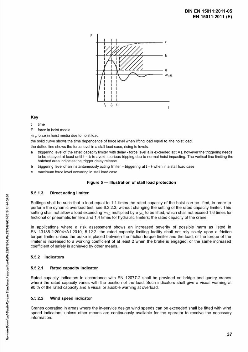
7/25/2019 DIN en 15011-2011 - Cranes - Bridge and Gantry Cranes
http://slidepdf.com/reader/full/din-en-15011-2011-cranes-bridge-and-gantry-cranes 39/95
EN 15011:2011 (E)
37
F
tt 1
t 2
t 3
a
b
c
m gH
Key
t time
F force in hoist media
mHg force in hoist media due to hoist load
the solid curve shows the time dependence of force level when lifting load equal to the hoist load.
the dotted line shows the force level in a stall load case, rising to level c.
a triggering level of the rated capacity limiter with delay - force level a is exceeded at t = t1, however the triggering needs
to be delayed at least until t = t3 to avoid spurious tripping due to normal hoist impacting. The vertical line limiting thehatched area indicates the trigger delay release.
b triggering level of an instantaneously acting limiter – triggering at t = t2 when in a stall load case
c maximum force level occurring in stall load case
Figure 5 — Illustration of stall load protection
5.5.1.3 Direct acting limiter
Settings shall be such that a load equal to 1,1 times the rated capacity of the hoist can be lifted, in order toperform the dynamic overload test, see 6.3.2.3, without changing the setting of the rated capacity limiter. This
setting shall not allow a load exceeding mRC multiplied by φ DAL to be lifted, which shall not exceed 1,6 times for
frictional or pneumatic limiters and 1,4 times for hydraulic limiters, the rated capacity of the crane.
In applications where a risk assessment shows an increased severity of possible harm as listed inEN 13135-2:2004+A1:2010, 5.12.2, the rated capacity limiting facility shall not rely solely upon a frictiontorque limiter unless the brake is placed between the friction torque limiter and the load, or the torque of thelimiter is increased to a working coefficient of at least 2 when the brake is engaged, or the same increased
coefficient of safety is achieved by other means.
5.5.2 Indicators
5.5.2.1 Rated capacity indicator
Rated capacity indicators in accordance with EN 12077-2 shall be provided on bridge and gantry craneswhere the rated capacity varies with the position of the load. Such indicators shall give a visual warning at90 % of the rated capacity and a visual or audible warning at overload.
5.5.2.2 Wind speed indicator
Cranes operating in areas where the in-service design wind speeds can be exceeded shall be fitted with windspeed indicators, unless other means are continuously available for the operator to receive the necessaryinformation.
DIN EN 15011:2011-05
7/25/2019 DIN en 15011-2011 - Cranes - Bridge and Gantry Cranes
http://slidepdf.com/reader/full/din-en-15011-2011-cranes-bridge-and-gantry-cranes 40/95
EN 15011:2011 (E)
38
Where a wind speed indicator is fitted it shall activate an audible warning at the wind speed at which shutdown shall be initiated.
NOTE Wind speed vst at which shut down should be initiated can be calculated as follows:
t vv p st ⋅−= 30022
where
v p is the permissible in-service wind speed, in metres per second;
t is the time needed to shut down the crane from any operating position, in minutes.
5.5.3 Motion limiters
5.5.3.1 General
Cranes shall be equipped with limiters at the end of each motion in accordance withEN 12077-2:1998+A1:2008, 5.6.1. Where electrical limiters are used, they shall actuate a category 0 orcategory 1 stop according to EN 60204-32, but allow movement in the opposite direction to a safe condition.
NOTE 1 Guidance regarding type and location of limiters are given in ISO 10245-5.
The horizontal motions of rail mounted cranes shall be provided with additional limiters, where there is need tolimit operation of the crane, trolley or load in certain areas.
NOTE 2 In some applications it is maybe desirable to fit slow-down limiters in addition to limiters at the end of motions.
5.5.3.2 Use of back-up limiter for hoist motion
A second (back-up) upper limiter of hoist motion independently activated from the first, complying withEN 12077-2 shall be used in high-risk applications as described in EN 13135-2. A second upper limiter shallalso be used on cranes where:
the failure of the first limiter results in the dropping of the load, that directly or indirectly causes anunacceptable high risk to persons and property: or
the intended use of the crane is such that the upper limit is approached frequently.
NOTE The second upper limiter should also be used to protect valuable properties, for example: power housecranes, shipyard cranes, harbour cranes, etc.
Following the operation of the second limiter, a restart shall only be possible by a reset action, e.g. by using akey-lockable hold-to-run control on the control stand or a manual reset button on the hoist. An indication of afailure of the first limiter, as required in EN 12077-2:1998+A1:2008, 5.6.1.4, shall be provided showing that areset action is necessary, after the second limiter has been triggered.
Indication and reset action are not necessary, if the second limiter is a friction torque limiter designed toaccommodate the movement energy.
5.5.3.3 Collision of cranes or trolleys
Buffers between the cranes or trolleys are sufficient systems for risk reduction, if they are able to absorb thekinetic energy resulting from the moving masses in such a way as to prevent the following:
a) the strength of the components of the crane installation being exceeded;
b) the falling or tilting of the cranes or trolleys;
DIN EN 15011:2011-05

7/25/2019 DIN en 15011-2011 - Cranes - Bridge and Gantry Cranes
http://slidepdf.com/reader/full/din-en-15011-2011-cranes-bridge-and-gantry-cranes 41/95
EN 15011:2011 (E)
39
c) the dropping of the load;
d) the load swaying in a hazardous manner.
In other cases, anti-collision systems shall be provided.
Where an anti-collision system is evaluated as being required, all relevant crane or trolley motions shall beequipped with the system. The anti-collision system shall have some or all of the following features dependingupon the assessment of the risks involved:
the ability to reduce the speed of approach of the crane(s) or trolley(s) moving towards a collision;
the ability to bring the moving crane(s) or trolley(s) to a stop before a collision occurs.
The forces resulting from kinetic energy of the collision shall also be taken into account with anti-collisionsystem unless the system meets the requirements of 5.3.4.1.
The driver shall not be exposed to a deceleration exceeding 4 m/s2.
NOTE Warning of approaching collisions can be required in some cases.
Where buffer end stops for the crane or the trolley are fixed by a bolt tightening friction device to provide thepossibility of adjustment of the travel range, there shall also be a positive locking device behind the end stopas a back-up means or the friction grip joint of the end stop construction shall be designed with a specific
resistance factor γ ss = 1,8, see prEN 13001-3-1.
5.5.4 Performance limiters
Performance limiters (see EN 12077-2:1998+A1:2008, 5.6.2.1) shall be provided where necessary, forexample:
a) limiting the lifting capacity locally where there are limitations due to load bearing capacity of the cranesupporting structures;
b) limiting of hoisting or travelling speed and/or acceleration/deceleration dependent upon the lifted load;
NOTE Limiting of deceleration can introduce additional hazards, and it can be necessary to limit the maximum
speed.
c) limiting of (travelling) speed and/or acceleration/deceleration dependent upon wind conditions;
d) limiting of lifting capacity dependent upon the type of load, for example increasing safety factors fordangerous lifts.
The operation of the performance limiters shall not cause additional hazards.
5.6 Man-machine interface
5.6.1 Controls and control stations
Controls and control stations shall comply with EN 13557 amended as follows:
The arrangement of the controls for cranes with cabins shall comply with ISO 7752-5. The logic of the controlarrangement shall be the same at each control station associated with the operation of the crane. Thearrangement of the controls for the cranes without cabins shall, where possible, also follow this logic.
The movement of a crane motion shall only be able to be initiated from the neutral position of the control.
DIN EN 15011:2011-05
7/25/2019 DIN en 15011-2011 - Cranes - Bridge and Gantry Cranes
http://slidepdf.com/reader/full/din-en-15011-2011-cranes-bridge-and-gantry-cranes 42/95
EN 15011:2011 (E)
40
NOTE More information on ergonomic design principles of controls and control stations is given in EN 614-1. Cabinsshould be constructed as specified in ISO 8566-5.
Windows shall be fitted with wipers and washers and designed so that the outside surface can be readilycleaned. The whole window unit shall be designed and installed so that it cannot fall outwards.
The cabin shall be located so that collision with the transported load is prevented. If this is not possible bylocation, the cabin shall be guarded with railings.
To avoid uncomfortable vibrations for the operator in a cabin, the natural frequency of the structure carryingthe cabin should not be less than 2 Hz. Where this requirement cannot be reasonably met, amplitude andduration of vibration should be minimized e.g. by using stepless controls. Informative guide values of lowestfrequencies are given in ISO 22986.
For gantry cranes the frequency of horizontal vibrations should be not less than 0,50 Hz.
5.6.2 Guarding and access
5.6.2.1 The crane shall have permanent access to all control stations, in accordance with EN 13586.
Where access is provided by means of a permanent personnel lift, it shall comply with EN 81-43.
If there is one exit only from a cabin controlled bridge or gantry crane, a risk assessment shall be made on theneed for a special evacuation means from the cabin.
NOTE For requirements not covered by EN standards noted above, guidance is given in ISO 11660-5 and EN 1993-6and in addition the following clearances are generally recommended, as examples:
clearance above the crane with access ways to the interrupted roof: 500 mm;
clearance between two cranes mounted above each other with access ways in either of the cranes: 500 mm;
clearance under the crane to the permanent obstacles: 500 mm;
clearance between the end carriage and the building taking into account the maximum skew position and allowable
wear and there is no permanent access: 50 mm.
5.6.2.2 If maintenance or inspection requires access to enclosures, the openings shall conform toEN 13586:2004+A1:2008, Table 6.
5.6.2.3 Some maintenance and inspection work may require the use of a safety harnesses. Where suchequipment is required attachment points in conformity with EN 795 shall be provided.
5.6.2.4 To avoid crushing and shearing hazards the minimum distance between moving parts within thecrane shall be in accordance with EN 349 unless equivalent safety is provided by other means, for example aperson detector and motion limiter system.
Where there is a danger of a shearing or falling hazard occurring on the access way, the transfer points shallbe provided with gates. These gates shall be fitted with an interlocking device that disables the relevantmotion.
5.6.2.5 For cranes travelling on rails on the floor or ground level, the end carriages or the foremost bogiesin both directions shall be equipped with rail sweepers and flexible contact protection.
NOTE These devices protect persons from getting to a hazardous contact with the crane. They need not affect thetravel drive system.
Where the crane travel rails are at a lower level than 2,5 m above ground they shall be guarded, for exampleby rail sweepers. The clearance between the rail and the sweeper shall be less than 5 mm at levels 0,5 m to2,5 m and less than 20 mm at levels 0 m to 0,5 m.
DIN EN 15011:2011-05

7/25/2019 DIN en 15011-2011 - Cranes - Bridge and Gantry Cranes
http://slidepdf.com/reader/full/din-en-15011-2011-cranes-bridge-and-gantry-cranes 43/95
EN 15011:2011 (E)
41
5.6.2.6 Open gears, chain drives and similar power transmissions in personnel working and traffic zonesshall be guarded in accordance with EN 953. Exceptionally, guarding of the large slewing gears may not berequired, if the drawing in point of the pinion/gear is located sufficiently remote from the access ways, inaccordance with EN ISO 13857.
5.6.3 Lighting
The manufacturer shall clarify needs for crane-mounted lights depending on the availability of other lights onsite. Attention shall be paid on lighting:
— on the working area;
— on access walkways, stairs and ladders;
— in machinery room and electric room.
When a crane will be used in a working place where general illumination level is less than 20 lux, it shall beequipped with lighting that provides local illumination of at least 50 lux on the working area.
NOTE These are minimum limits, which should be specified higher when required by the accuracy of the work.
Lighting levels on the crane shall be a minimum value of:
— cabins, min. 200 lux;
— machinery room, min. 100 lux;
electric room, 100 lux.
A socket for extra local light shall be provided in each room including the cabin, in an electrical cubicle, andother points requiring maintenance, if the fixed lighting and/or the ambient illumination is not adequate.
Cranes with a ride-on operator shall be equipped with battery powered emergency exit lighting, unless there isemergency illumination on site.
5.6.4 Reduction of noise by design
5.6.4.1 General
Normally noise is not a significant hazard in bridge and gantry cranes. Noise can be a significant hazard incases where the operator’s position is situated close to one or more of the mechanisms or componentsmentioned in 5.6.4.2, when their power level or operational speed is high.
When noise is a significant hazard there is need for low noise design. In this case the methodology for lownoise design in EN ISO 11688-1 shall be considered.
NOTE EN ISO 11688-2 gives useful information on noise generation mechanisms in machinery.
5.6.4.2 Main sources of noise
On bridge and gantry cranes the main sources of noise are the following:
hoisting mechanism (motor, gear, brakes);
trolley traversing mechanism (motor, gear, brakes, especially rail/wheel contact);
crane travel mechanism (motor, gear, brakes, especially rail/wheel contact);
crane festoon (small festoon trolley wheels may be noisy);
DIN EN 15011:2011-05
7/25/2019 DIN en 15011-2011 - Cranes - Bridge and Gantry Cranes
http://slidepdf.com/reader/full/din-en-15011-2011-cranes-bridge-and-gantry-cranes 44/95
EN 15011:2011 (E)
42
trolley festoon;
electrical cubicles;
external devices, e.g. motor fans;
hydraulic pumps, either on the trolley or in the load lifting attachment (especially the grabs);
combustion engines and power generators.
5.6.4.3 Measures to reduce noise at the source
Typical measures to reduce noise are:
selection of low noise components;
use of elastic mountings that prevent the transmission of structure born noise from the components to the
structures.
Other measures of identical or better efficacy can be used.
5.6.4.4 The protective measures
Typical measures are:
the use of noise reducing housing around noisy components;
the use of improved noise isolation in the cabin, if any.
5.6.4.5 Determination of noise emission values
Noise emission values shall be determined as specified in the noise test code given in Annex G.
NOTE Effects of the supporting structure and the surrounding building (if applicable) are outside of the scope of thisEuropean Standard.
5.6.4.6 Information on residual noise
The information on residual noise shall be given to the user, see Clause 7.
5.7 Equipment for warning
5.7.1 General
Warning labels and markings shall be provided to inform the crane operator, service personnel, inspectors,slingers and other persons on or near the crane about the hazards related to the crane and its operations, andon the action they would need to take to minimize the risks.
NOTE 1 EN ISO 12100-2 gives the principles of presenting hazard information using labels.
NOTE 2 EN 12644-2 gives requirements and information on the marking of cranes.
NOTE 3 Visual warning means are safety colours, pictorial signs, text warnings and warning lights.
DIN EN 15011:2011-05

7/25/2019 DIN en 15011-2011 - Cranes - Bridge and Gantry Cranes
http://slidepdf.com/reader/full/din-en-15011-2011-cranes-bridge-and-gantry-cranes 45/95
EN 15011:2011 (E)
43
5.7.2 Warning markings
Warning markings shall be of contrasting colours, which will cause the markings to stand out in the operatingenvironment, in accordance with ISO 3864 (all parts). Warning markings shall have a reasonable life for theanticipated operating environment.
5.7.3 Warning lights
Travelling mechanisms or leading chassis of rail-mounted cranes travelling on the floor or at ground level shallbe equipped in both directions with warning lights, which are activated during the travelling movement of thecrane. Hand powered cranes are exempt from this requirement.
The flashing warning lights shall be installed in such a manner as to attract the attention of persons in thehazard zones. The colour of the flashing warning lights shall be yellow or amber with a flashing rate in therange 60/min to 120/min.
5.7.4 Cableless control warning light
Bridge and gantry cranes equipped with cableless controls shall be equipped with a red warning light, which isactivated as long as the cableless control is switched on.
5.7.5 Acoustic warning means
Bridge and gantry cranes shall have an acoustic warning device to be actuated by the operator. Floor-controlled cranes where the control system arrangement requires the operator to stay in the vicinity of the loadare exempt from this requirement (pendant control).
NOTE An automatically activated acoustic warning should be considered, where:
a moving crane or load can create a crushing or shearing hazard to persons; and
the crane operator has poor or no vision of the hazard zone; and
free space and escape routes in the hazard zone are limited.
5.7.6 Location of the visual display unit
Location of the visual display units, when fitted, shall be in accordance with EN 894-1 and EN 894-2 tominimize the operator's head movements but still avoiding unnecessary hindrance of the field of vision overthe working area.
6 Verification of safety requirements and/or protective measures
6.1 General
Conformity to the safety requirements and/or protective measures specified in Clause 5 shall be verified bythe methods given in Tables 8 and 9. Where applicable, individual components may be separately verified ortested in accordance with their relevant standards.
DIN EN 15011:2011-05

7/25/2019 DIN en 15011-2011 - Cranes - Bridge and Gantry Cranes
http://slidepdf.com/reader/full/din-en-15011-2011-cranes-bridge-and-gantry-cranes 46/95
EN 15011:2011 (E)
44
6.2 Types of verification
Table 8 — Verification methods for requirements
Method of verification Letter symbol
Visual inspection V
Measurement M
Testing T
Calculation C
Engineering assessment EA
DIN EN 15011:2011-05

7/25/2019 DIN en 15011-2011 - Cranes - Bridge and Gantry Cranes
http://slidepdf.com/reader/full/din-en-15011-2011-cranes-bridge-and-gantry-cranes 47/95
EN 15011:2011 (E)
45
Table 9 — Methods to be used to verify conformity with the safety requirementsand/or protective measures
Clausenumber
Title of the clause Method of verification
5.1 General Methods specified in referredstandards
5.2 Requirements for strength and stability This clause describes themethods of verification of thestrength and stability of thecrane by calculation
5.2.1.1 Selection of service conditions V, C
5.2.1.2 Selection of loads and load combinations V
5.2.1.3.1 Hoisting and gravity effects acting on the mass ofthe crane
C
5.2.1.3.2 Determination of factor φ2 C, T
5.2.1.3.3 Load caused by travelling on uneven surfaces C
5.2.1.3.4 Loads caused by acceleration of drives C, M5.2.1.4 Loads caused by skewing C
5.2.1.5 Overload condition C
5.2.1.6 Test loads V, Testing according to 6.3
5.2.1.7 Design basis for multi point lifting in cases where thelifting forces are not equalized
C, EA
5.2.1.8 Conditions of use of permissible stress method andlimit state method
EA
5.2.2.1 Limit states and proof of competence of structuralmembers
C
5.2.2.2 Limit states of mechanical components C
5.2.2.3 Local stresses from wheel loads C
5.2.2.4 Proof of strength of lifting points C
5.2.2.5 Elastic deformation C, T5.2.2.6 Vibration frequencies of crane girders C, T
5.2.3.1 General requirements C
5.2.3.2 Gantry crane configurations C
5.2.3.3 Design of tie-downs C
5.2.3.4 Stability of rubber tyred gantry crane (RTG) C
5.3.1 Physical environment and operating conditions V, EA
5.3.2 Electrical supply V, C, M
5.3.3 Protection against electric shock by direct contact V
5.3.4.1 General V, EA
5.3.4.2 Suspension (by-pass) of safeguarding for setting,testing and maintenance purposes
V
5.3.4.3 Combined start and stop controls EA5.3.5.1 Operator interface and mounted control devices,
GeneralV, T
5.3.5.2 Push-buttons V
5.3.5.3 Devices for emergency stop V, T
5.3.6 Power driven motions V, EA
5.4.1 Non-electrotechnical equipment, General Methods specified in referredstandards
5.4.2.1 Braking systems, General T
5.4.2.2 Mechanical service brakes in power driven motions T, EA
5.4.2.3 Brakes for hoisting movements T, V
5.4.3.1 Use of serial hoist units V
5.4.3.2 Variable rated capacity T
5.4.3.3 Variable number of hoist units on the bridge crane C, T5.4.3.4 More than one hoist unit permanently on the bridge C, T
5.4.3.5 Hooks for handling of hot molten metal C, V
DIN EN 15011:2011-05

7/25/2019 DIN en 15011-2011 - Cranes - Bridge and Gantry Cranes
http://slidepdf.com/reader/full/din-en-15011-2011-cranes-bridge-and-gantry-cranes 48/95
EN 15011:2011 (E)
46
Table 9 — Methods to be used to verify conformity with the safety requirementsand/or protective measures (continued)
Clausenumber
Title of the clause Method of verification
5.4.3.6 Boom hoisting T, V5.4.4.1 Friction drive capability C, T
5.4.4.2 Hand driven trolleys and cranes T, V
5.4.4.3 Drive characteristics of the rubber tyred gantrycrane (RTG)
C, T
5.4.4.4 Anchoring in out-of service wind conditions C. V
5.4.4.5 Derailment protection C, V
5.4.4.6 Guide roller design V
5.4.4.7 End stops V
5.4.5.1 Friction drive capability C, T
5.4.5.2 Parking in out-of-service condition C, T
5.4.5.3 Slew bearing C, M
5.4.6.1 The tolerances for rail mounted cranes and tracks M5.4.6.2 The tolerances for alignment of travelling wheels of
RTGM
5.4.7 Gear drives C
5.4.8.1 Hot surfaces V
5.4.8.2 Laser beams T
5.4.8.3 Fire hazard V
5.4.8.4 Processed materials and substances, usedmaterials, fuels
V, EA
5.4.8.5 Tandem operation of cranes/trolleys V, T
5.5.1.1 Rated capacity limiters, General C, T
5.5.1.2 Indirect acting limiter C, T
5.5.1.3 Direct acting limiter C, T
5.5.2.1 Rated capacity indicator T
5.5.2.2 Wind speed indicator V, EA, T
5.5.3.1 Motion limiters, General T
5.5.3.2 Use of back-up limiter for hoist motion EA, T
5.5.3.3 Collision of cranes or trolleys T, EA
5.5.4 Performance limiters T, EA
5.6.1 Control and control stations V, T
5.6.2 Guarding and access V, T, M
5.6.3 Lighting V, EA, M
5.6.4.1 Noise, General M, EA
5.6.4.2 Main sources of noise T
5.6.4.5 Determination of noise emission values C, M
5.6.4.6 Information on residual noise V5.7.1 Equipment for warning, General V, EA
5.7.2 Warning markings V
5.7.3 Warning lights V, T
5.7.4 Cableless control warning light V, T
5.7.5 Acoustic warning means T
5.7.6 Location of the visual display unit V
6.3 Fitness for purpose testing
6.3.1 General
The crane shall be tested before being taken into service to ensure that it is able to fulfil its specified functionssafely. The test results shall be recorded.
DIN EN 15011:2011-05
7/25/2019 DIN en 15011-2011 - Cranes - Bridge and Gantry Cranes
http://slidepdf.com/reader/full/din-en-15011-2011-cranes-bridge-and-gantry-cranes 49/95
EN 15011:2011 (E)
47
The tests shall include:
a) functional tests according to 6.3.2.1; and
b) load tests according to
1) 6.3.2.2 and 6.3.2.3; or
2) 6.3.2.4.
At the conclusion of testing, all limiters that may have been either disengaged or adjusted to facilitate suchtesting shall be reactivated and returned to their prescribed operational settings.
6.3.2 Tests
6.3.2.1 Functional test
All motions of the crane shall be operated throughout their range of movements, without load, up to theirmaximum operating speeds. Motion limiters and buffer positions shall initially be approached and contactmade at slow speed prior to contact being made at maximum operational speed. Where buffer stops are usedwithout other motion limiters, they shall only be contacted once at 100 % speed.
During these tests the crane shall be monitored to check that it operates smoothly, the braking systemsoperate effectively and motion limiter and indicator settings are accurate.
All functions of the crane equipment shall be tested, particularly those related to safety, including back-upbrake sequencing, for correct operation.
When installed, a second (back up) upper limiter for hoist range shall be tested by disconnecting the firstlimiter and then the motion driven through at both low and high speed.
6.3.2.2 Static test
Cranes fitted with power-driven hoists shall be tested with a load, positioned 100 mm to 200 mm above theground and being the greater of:
all suspended loadings including that of 125 % of the rated capacity; or
the hoist load multiplied by factor φ2 that has been used in design calculations in load combination A.
Cranes, that are equipped only with direct acting limiters, shall be tested in accordance with the above loadvalues, or with a load corresponding to the direct acting limiter setting minus 5 % of the rated capacity,whichever is the greater.
Cranes fitted with hand powered hoists shall be tested according to EN 13157.
The test shall be carried out in the critical trolley positions, such as the middle span, extreme positions oftraverse including any cantilever outreaches, so as to qualify overload and stability requirements. Wheremovements are performed during the test, they shall be made separately; a new movement shall not beinitiated until vibrations caused by the preceding movement have dampened out.
Where cranes are equipped with more than one hoist mechanism that can be used separately, they shall betested individually prior to the crane test unless previously tested by the manufacturer. The crane shall betested with the most unfavourable loading combinations of the hoist mechanisms in the specified use.
The test load shall be applied for a period necessary to make the observations and measurements to evaluate
the crane competence.
Tests are considered successful if no fractures, permanent deformations or damages affecting the function orsafety of the crane are visible and if no connections have loosened or show signs of damage.
DIN EN 15011:2011-05

7/25/2019 DIN en 15011-2011 - Cranes - Bridge and Gantry Cranes
http://slidepdf.com/reader/full/din-en-15011-2011-cranes-bridge-and-gantry-cranes 50/95
EN 15011:2011 (E)
48
NOTE Minor permanent deformations such as settling are acceptable providing they do not affect the functioning ofthe crane.
6.3.2.3 Dynamic test
Dynamic tests shall be performed with a test load that is at least 110 % of the rated capacity.The tests shall include repeated starting and stopping of each motion, including all combined movements asprovided by the intended use over the whole sequence and range of the movements.
During these tests the crane shall be continuously monitored to check for:
smooth operation of the crane;
effective operation of the braking systems;
effectiveness and accuracy of limiting and indicating devices;
that the hoist motor electrical current is proportional to the name plate or manufacturer's publishedvalues.
The protection performance of the rated capacity limiter shall be tested by lifting a load having a massbetween 110 % to 125 % of the rated capacity as follows:
start lifting without prestressing the hoisting medium;
use maximum speed that the control system allows in this situation;
run the hoist mechanism up to the triggering point of the rated capacity limiter.
The dynamic tests are considered successful if the components in question have fulfilled their function, the
subsequent examination does not reveal any damage to the drive or supporting structure and if no connectionhas loosened or been damaged.
NOTE The combined effect of the loaded crane/trolley when in collision with buffers should be proved by calculation,see EN 13001-2.
6.3.2.4 Alternative test method for cranes fitted with power driven hoists
When the design of the crane allows, the tests in 6.3.2.2 and 6.3.2.3 may be replaced with a dynamic test,using the maximum normal speeds for each drive movement with a load obtained by dividing the test load
specified in 6.3.2.2 by the dynamic coefficient φ6 of test conditions, (φ6 = 0,5(1 + φ2), see EN 13001-2).
The test is considered successful if the requirements of 6.3.2.2 and 6.3.2.3 are fulfilled.
Where instability is a hazard for the crane a static test shall be undertaken, see 6.3.2.2.
7 Information for use
7.1 General
The crane shall be provided with instructions in accordance with EN ISO 12100-2:2003, Clause 6, andEN 12644-1 as amended by in this standard.
The design life of the crane based upon the selected service conditions, see 5.2.1.1, shall be indicated by themanufacturer in years in relation to load and usage.
DIN EN 15011:2011-05

7/25/2019 DIN en 15011-2011 - Cranes - Bridge and Gantry Cranes
http://slidepdf.com/reader/full/din-en-15011-2011-cranes-bridge-and-gantry-cranes 51/95
EN 15011:2011 (E)
49
NOTE The design life of the crane is defined for the purpose of calculation and should not be considered as aguarantee of life. However, it can be used as guidance for long term maintenance and refurbishment purposes, seeISO 12482-1. Monitoring the use can be achieved by the use of cycle counter devices, see EN 13135-2 for specialapplications.
7.2 Operator’s manual
Where there is more than one hoist mechanism on the crane or where there are any limitations for the ratedcapacity on certain areas of the girder or boom, a description of the permissible loads of each hoist and thepermissible combinations of loads on the hoists shall be given. Descriptions of the operation of the load limiterand indicator systems shall also be included.
Information regarding the operation of performance limiters shall be provided in the instruction manual.
Instructions shall be given on safe slinging to avoid accidental releasing from the hook and the load falling.The manual shall warn about remaining hazards related to a falling load or a part of the load in case of afailure in compiling and attaching the load.
The manual shall give information on correct operation of the crane by the operator to avoid impact, by themoving load, with persons or property.
The manual shall describe the necessary daily checks to ensure that, e.g. the motion limiters, indicators andwarning devices are performing satisfactorily.
The instructions shall inform the correct ways of using multiple motion commands in order to suppress loadsway.
The manual shall describe the procedure for shutting down the crane and leaving it in an out-of-servicecondition.
The manual shall indicate the manner in which the operator shall receive instruction/information regarding
current wind speeds and the action to be taken to shut down the crane.
Where the load lifting attachment or the typical loads have such a shape that allows a person to enter andstay on during lifting, the crane operator shall be instructed to refuse the lifting the persons.
For hand operated gantry cranes intended for free travelling (not rail guided) information shall be given on therestrictions of travelling when the crane is loaded.
Where there is a risk of a lifting attachment being locked to the load during loss of power and the load is stillconnected to a downward moving support (e.g. container ship), instructions shall be provided on a manualmeans for releasing the hoist medium force (e.g. brakes) during loss of power. Similar situations could berelieved by the same procedures.
7.3 User’s manual
7.3.1 General
The user’s manual shall inform on safe use of cranes and training for the slingers and the crane operator.
NOTE 1 Information is available in ISO 9926-1, ISO 12480-1 and ISO 15513.
Where crane generated or ambient noise can disturb communication between the operator and the slingers orother personnel the user's manual shall draw attention to the arrangement of other means of communication,e.g. use of hand signals, radio.
Instructions as to the type and gradient of the surface on which RTG's can operate shall be provided.Instructions for maintenance of working conditions, e.g. removal of snow and ice and improving traction byusing salt or sand, shall also be provided.
DIN EN 15011:2011-05
7/25/2019 DIN en 15011-2011 - Cranes - Bridge and Gantry Cranes
http://slidepdf.com/reader/full/din-en-15011-2011-cranes-bridge-and-gantry-cranes 52/95
EN 15011:2011 (E)
50
The manual shall state that any modified clearances around the crane shall conform to 5.6.2.
The forces transmitted by the crane to the supporting structures shall be provided.
NOTE 2 Information on the forces to be taken into account is given in Annex H.
Emission sound pressure levels at the operator positions, generated by the crane, determined in accordancewith Annex G shall be indicated.
Where the A-weighted emission sound pressure level at operator positions exceeds 80 dB(A), the A-weightedsound power level emitted by the crane shall also be indicated.
As it may be impractical to reach acceptable environmental conditions for the measuring of the sound powerlevel in accordance with EN ISO 3744:2010, Annex A or the crane is very large, it is acceptable to determineand declare the sound pressure levels in specified locations around the crane as described in Annex G.
7.3.2 Instructions for installation
Where the manufacturer will not carry out the assembly or erection of the crane, instructions on erection,assembly and fitness for purpose testing (see 6.3.2) shall be given.
7.3.3 Instructions for maintenance
Instructions for maintenance shall comply with EN 12644-1, EN 60204-32 and EN 13135-2 as amended in thissubclause.
Instructions shall be given on:
inspection methods and intervals;
criteria for the replacement of components;
replacement of worn out or damaged parts;
tests to be carried out after replacement of components;
test to be carried out periodically.
NOTE 1 Periodic test can be subject to national regulations.
Abrasion and wearing limits shall be given for components subject to wear, for example:
sheaves;
ropes (for information, see ISO 4309), pins and rope terminals;
rope drums;
hooks;
brake linings, discs, drums;
couplings;
current collectors used in slip-ring systems and in conductor bars;
wheels (steel or rubber tyres);
chains and sprockets;
DIN EN 15011:2011-05

7/25/2019 DIN en 15011-2011 - Cranes - Bridge and Gantry Cranes
http://slidepdf.com/reader/full/din-en-15011-2011-cranes-bridge-and-gantry-cranes 53/95
EN 15011:2011 (E)
51
trolley and travel rails (for information, see ISO 12488-1);
guide rollers.
Instructions shall also be given for maintaining the braking capacity of mechanical brakes which are subject to
minimal wear due to the performance of their operational systems.
Instructions shall be provided to verify (or enable checking) the operation and setting of the safety systems, forexample the rated capacity limiter.
NOTE 2 This can require marking of the original setting values on the equipment or in the documentation.
Information shall be given on required personal protective equipment, such as harnesses against protectionfor falling from heights, and on their attachment points.
Potentially hot components shall be identified, and their guarding and/or marking shall be described.
Where necessary, instructions on the disposal of materials that are replaced during maintenance and final
dismantling shall be given.
The instructions for checking the condition of an outdoor crane after a lightning strike shall include thefollowing:
Where a lightning strike has occurred or considered to have occurred, the following checks shall be carriedout before the crane is returned to service:
the wire rope shall be visually checked;
rail wheels and wheel bearings shall be checked for abnormal noise;
functional checks of the crane proving limiters, indicating devices etc shall be carried out.
Instructions for rubber tyred cranes shall include instructions on inspection and maintenance of tyres, wheelsand rims, including at least the inflation of tyres and the dismounting of multi-piece rims.
7.4 Marking of rated capacities
The rated capacity of the crane is the maximum load permitted to be lifted with hoist mechanismssimultaneously under the fixed load lifting attachments. The rated capacity shall be clearly marked on themain girder of the crane, examples: "50 t" or "RC 50 t".
The rated capacity of each hoist mechanism shall be marked at least on their fixed load lifting attachment.
If there are any limitations related to the simultaneous use of the hoist mechanisms, they shall be markedeither on the control consoles or on the girders. For examples, see Table 10.
If the rated capacity of the crane is limited to lower values on certain areas of the girder or the boom, suchareas and their rated capacity shall be marked clearly on the structure.
The different rated capacities of the different modes of operation (see 5.4.3.2) shall be clearly marked on thecrane.
DIN EN 15011:2011-05

7/25/2019 DIN en 15011-2011 - Cranes - Bridge and Gantry Cranes
http://slidepdf.com/reader/full/din-en-15011-2011-cranes-bridge-and-gantry-cranes 54/95
EN 15011:2011 (E)
52
Table 10 — Examples of marking of permissible combinations of hoist mechanisms
No. Description of limitations Marking of permissible combinations
1. Any hoist may be used together with the others H1+H2+H3
2. Hoist 1 may be used together with hoist 2 or with hoist 3simultaneously; hoist 2 and 3 shall not be used together
H1+H2 / H1+H3
3. Hoist 1 and hoist 2 may be used together or hoist 3separately; hoist 3 shall not be used together withhoist 1 or 2
H1+H2 / H3
4. Any hoist shall be used just alone; no combinationspermissible
H1 / H2 / H3
NOTE In each example the rated capacity limiter system prevents the rated capacity of the crane and eachindividual hoist being exceeded.
DIN EN 15011:2011-05
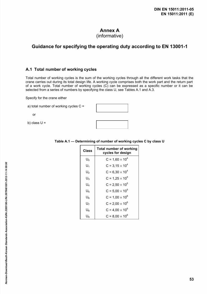
7/25/2019 DIN en 15011-2011 - Cranes - Bridge and Gantry Cranes
http://slidepdf.com/reader/full/din-en-15011-2011-cranes-bridge-and-gantry-cranes 55/95
EN 15011:2011 (E)
53
Annex A(informative)
Guidance for specifying the operating duty according to EN 13001-1
A.1 Total number of working cycles
Total number of working cycles is the sum of the working cycles through all the different work tasks that thecrane carries out during its total design life. A working cycle comprises both the work part and the return partof a work cycle. Total number of working cycles (C) can be expressed as a specific number or it can beselected from a series of numbers by specifying the class U, see Tables A.1 and A.3.
Specify for the crane either
a) total number of working cycles C =
or
b) class U =
Table A.1 — Determining of number of working cycles C by class U
ClassTotal number of working
cycles for designU0 C = 1,60 × 10
4
U1 C = 3,15 × 10⁴
U2 C = 6,30 × 10⁴
U3 C = 1,25 × 10⁵
U4 C = 2,50 × 10⁵
U5 C = 5,00 × 10⁵
U6 C = 1,00 × 10⁶
U7 C = 2,00
× 10
6
U8 C = 4,00 × 10⁶
U9 C = 8,00 × 10⁶
DIN EN 15011:2011-05
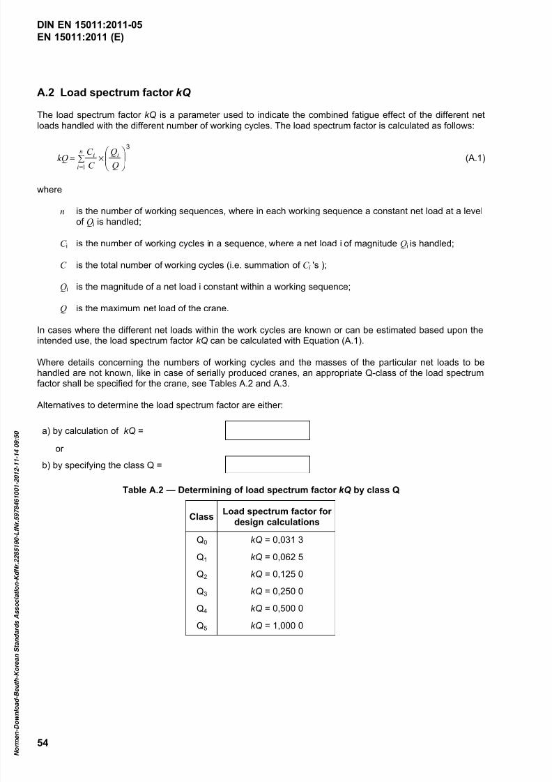
7/25/2019 DIN en 15011-2011 - Cranes - Bridge and Gantry Cranes
http://slidepdf.com/reader/full/din-en-15011-2011-cranes-bridge-and-gantry-cranes 56/95
EN 15011:2011 (E)
54
A.2 Load spectrum factor kQ
The load spectrum factor kQ is a parameter used to indicate the combined fatigue effect of the different net
loads handled with the different number of working cycles. The load spectrum factor is calculated as follows:
3
1
×∑=
= Q
Q
C
C kQ i
n
i
i (A.1)
where
n is the number of working sequences, where in each working sequence a constant net load at a levelof Qi is handled;
C i is the number of working cycles in a sequence, where a net load i of magnitude Qi is handled;
C is the total number of working cycles (i.e. summation of C i 's );
Qi is the magnitude of a net load i constant within a working sequence;
Q is the maximum net load of the crane.
In cases where the different net loads within the work cycles are known or can be estimated based upon theintended use, the load spectrum factor kQ can be calculated with Equation (A.1).
Where details concerning the numbers of working cycles and the masses of the particular net loads to behandled are not known, like in case of serially produced cranes, an appropriate Q-class of the load spectrumfactor shall be specified for the crane, see Tables A.2 and A.3.
Alternatives to determine the load spectrum factor are either:
a) by calculation of kQ =
or
b) by specifying the class Q =
Table A.2 — Determining of load spectrum factor kQ by class Q
ClassLoad spectrum factor for
design calculations
Q0 kQ = 0,031 3
Q1 kQ = 0,062 5
Q2 kQ = 0,125 0
Q3 kQ = 0,250 0
Q4 kQ = 0,500 0
Q5 kQ = 1,000 0
DIN EN 15011:2011-05

7/25/2019 DIN en 15011-2011 - Cranes - Bridge and Gantry Cranes
http://slidepdf.com/reader/full/din-en-15011-2011-cranes-bridge-and-gantry-cranes 57/95
EN 15011:2011 (E)
55
Table A.3 — Guidance for selection of classes U and Q, bridge and gantry cranes
No. Type of operation U-class Q-class
1 Hand powered cranes U0 – U2 Q1 – Q4
2 Assembly and maintenance cranes, intermittent operation U1 – U3 Q0 – Q2
3 Workshop cranes in general, hook service U2 – U5 Q0 – Q2
4 Factory and warehouse cranes, intermittent operation U2 – U5 Q1 – Q3
5 Warehouse cranes, continuous operation U5 – U8 Q1 – Q3
6 Paper mill cranes in process operation U3 – U5 Q3 – Q5
7 Shipbuilding cranes, hook service U2 – U5 Q1 – Q3
8 Cranes in steel production processes U4 – U6 Q3 – Q5
9 Terminal cranes, rubber tyred or rail mounted U5 – U7 Q2 – Q3
10 Ship to shore container cranes U6 – U8 Q2 – Q3
11 Unloading cranes, grabbing or magnet service U6 – U9 Q3 – Q5
12 Scrap-yard cranes, grabbing or magnet service U6 – U8 Q3 – Q5
13 Waste handling cranes in grabbing service U5 – U8 Q3 – Q5
Where the planned throughput of the crane is known, the selected classification U can be verified bycomparing the throughput calculated using the classification parameters with the planned throughput asfollows
T
C mm av ×= (A.2)
where
m is the throughput per year;
C is the number of work cycles during design life;
mav is the average lifted mass;
T is the design life in years.
NOTE The throughput of the crane can differ from that of the plant throughput, e.g. the possible multiple handling ofthe same load.
A.3 Average motion displacements
Duty of each crane motion is specified through average motion displacements over the work cycles of thecrane. For bridge and gantry cranes the motions are typically hoisting, trolley traversing and crane travelling.
An example is illustrated in Figure A.1.
Where crane operating displacements, loads and load locations are known, they should be used in design
calculations. In the absence of such information the average displacement method detailed below should beused.
DIN EN 15011:2011-05
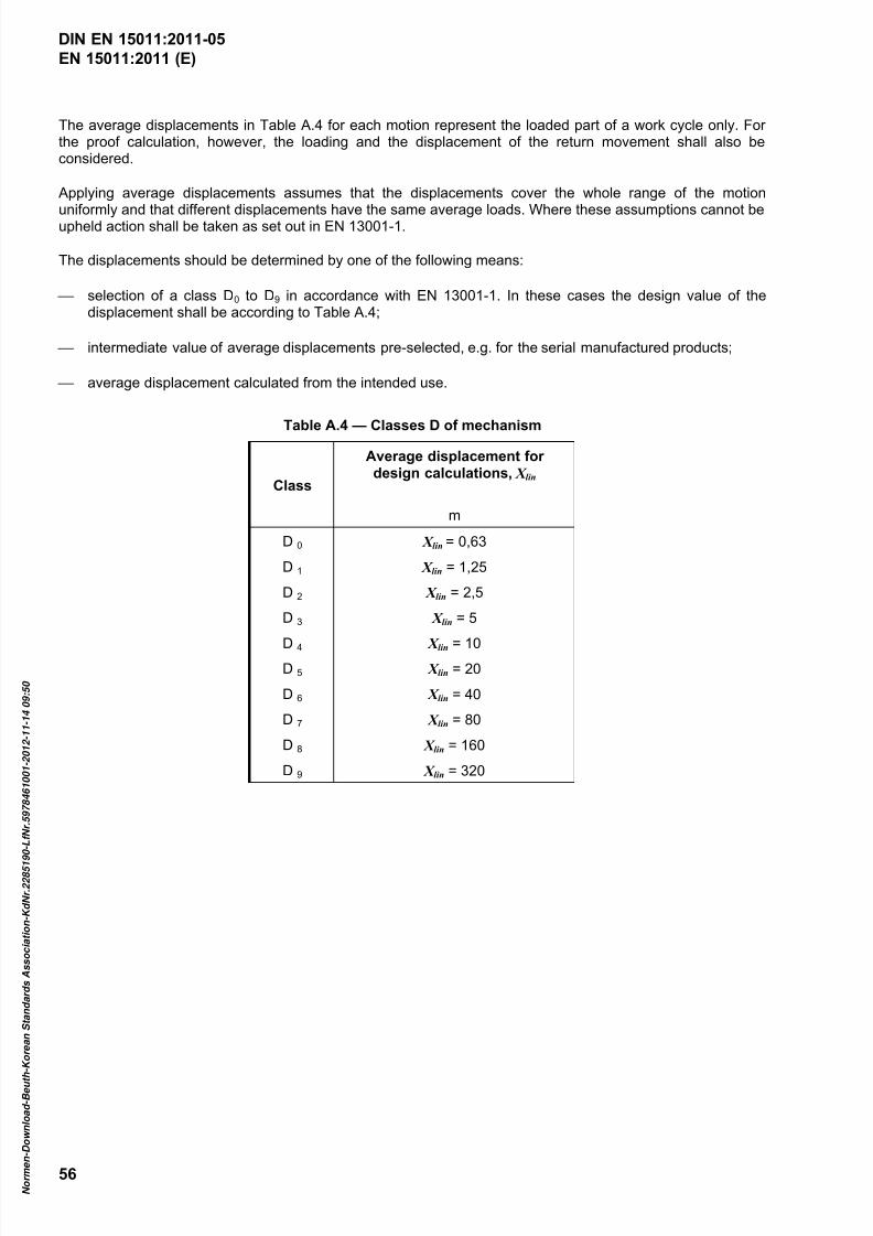
7/25/2019 DIN en 15011-2011 - Cranes - Bridge and Gantry Cranes
http://slidepdf.com/reader/full/din-en-15011-2011-cranes-bridge-and-gantry-cranes 58/95
EN 15011:2011 (E)
56
The average displacements in Table A.4 for each motion represent the loaded part of a work cycle only. Forthe proof calculation, however, the loading and the displacement of the return movement shall also beconsidered.
Applying average displacements assumes that the displacements cover the whole range of the motion
uniformly and that different displacements have the same average loads. Where these assumptions cannot beupheld action shall be taken as set out in EN 13001-1.
The displacements should be determined by one of the following means:
selection of a class D0 to D9 in accordance with EN 13001-1. In these cases the design value of thedisplacement shall be according to Table A.4;
intermediate value of average displacements pre-selected, e.g. for the serial manufactured products;
average displacement calculated from the intended use.
Table A.4 — Classes D of mechanism
Class
Average displacement fordesign calculations, X lin
m
D 0 X lin = 0,63
D 1 X lin = 1,25
D 2 X lin = 2,5
D 3 X lin = 5
D 4 X lin = 10D 5 X lin = 20
D 6 X lin = 40
D 7 X lin = 80
D 8 X lin = 160
D 9 X lin = 320
DIN EN 15011:2011-05
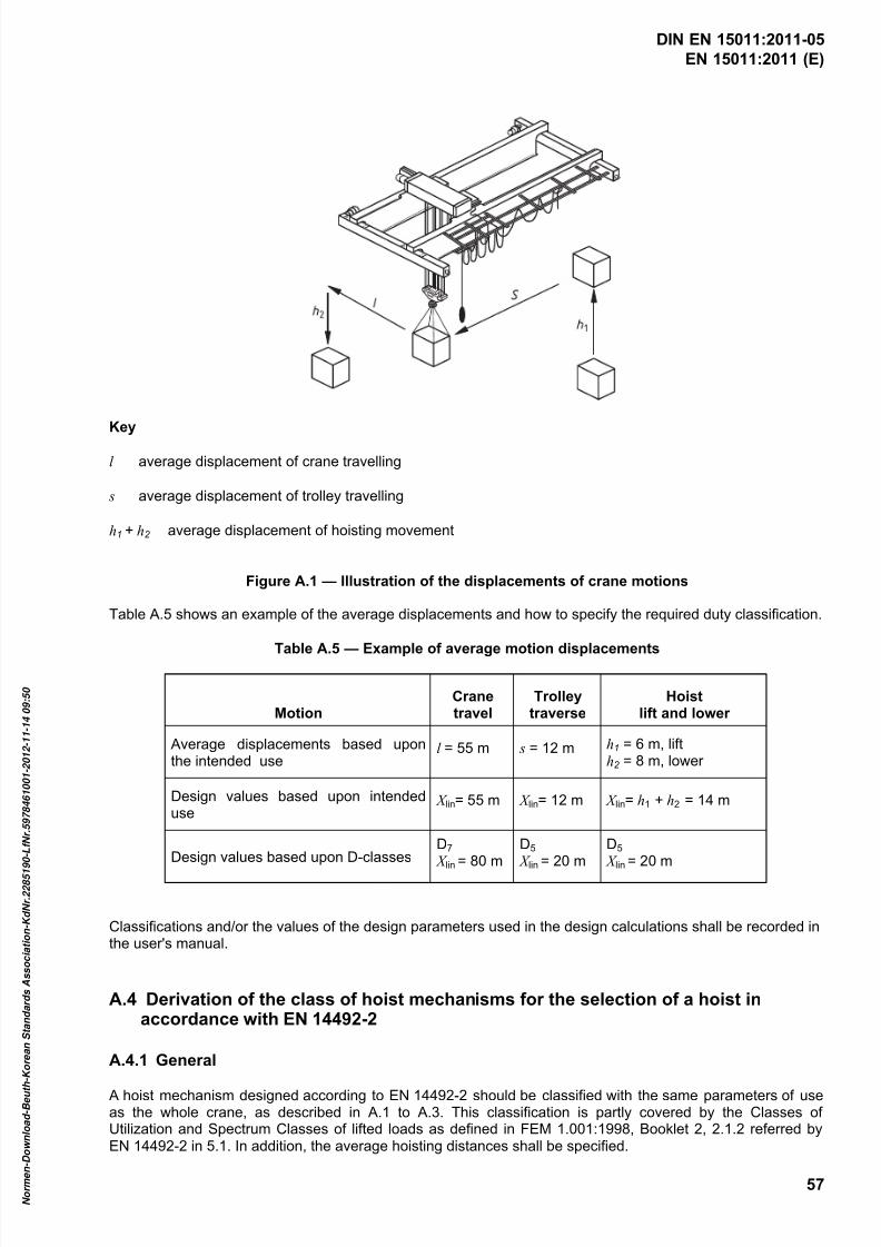
7/25/2019 DIN en 15011-2011 - Cranes - Bridge and Gantry Cranes
http://slidepdf.com/reader/full/din-en-15011-2011-cranes-bridge-and-gantry-cranes 59/95
EN 15011:2011 (E)
57
Key
l average displacement of crane travelling
s average displacement of trolley travelling
h1 + h2 average displacement of hoisting movement
Figure A.1 — Illustration of the displacements of crane motions
Table A.5 shows an example of the average displacements and how to specify the required duty classification.
Table A.5 — Example of average motion displacements
MotionCranetravel
Trolleytraverse
Hoistlift and lower
Average displacements based uponthe intended use
l = 55 m s = 12 m h1 = 6 m, lifth2 = 8 m, lower
Design values based upon intendeduse
X lin= 55 m X lin= 12 m X lin= h1 + h2 = 14 m
Design values based upon D-classesD7 X lin = 80 m
D5 X lin = 20 m
D5
X lin = 20 m
Classifications and/or the values of the design parameters used in the design calculations shall be recorded inthe user's manual.
A.4 Derivation of the class of hoist mechanisms for the selection of a hoist inaccordance with EN 14492-2
A.4.1 General
A hoist mechanism designed according to EN 14492-2 should be classified with the same parameters of useas the whole crane, as described in A.1 to A.3. This classification is partly covered by the Classes ofUtilization and Spectrum Classes of lifted loads as defined in FEM 1.001:1998, Booklet 2, 2.1.2 referred byEN 14492-2 in 5.1. In addition, the average hoisting distances shall be specified.
DIN EN 15011:2011-05
7/25/2019 DIN en 15011-2011 - Cranes - Bridge and Gantry Cranes
http://slidepdf.com/reader/full/din-en-15011-2011-cranes-bridge-and-gantry-cranes 60/95
EN 15011:2011 (E)
58
The appropriate class of mechanism according to FEM 1.001:1998, Booklet 2 (ISO 4301-1:1986) shall bederived using the parameters of the crane (see A.1. to A.3). A.4.2 to A.4.3 give guidance for the selection ofthe class of the mechanism according to the crane specification.
Where the selected hoist classification does not comply with the design life of the crane, the two differing
design lives, expressed in years, should be stated in the user's manual.
A.4.2 Conversion of the load spectrum factor
The load spectrum factor and class defined in A.2 are based on the relative net loads and relative number oflifts. The load spectrum factor and class of the mechanism according to FEM 1.001 are based upon therelative hoist loads and run times of the hoist mechanism. Therefore, the load spectrum defined for the craneuse shall be converted to the load spectrum of the mechanism. Figure A.2 illustrates the conversion.
The net load comprises the payload (the actual mass moved by the crane) and a non-fixed load-liftingattachment, if such is used. The mass of the non-fixed load-lifting attachment is a part of the rated capacity ofthe hoist and decreases the capacity remaining for the payload.
When the load spectrum factor according to A.2 is determined, the return motion without the payload is notconsidered. When the load spectrum factor for the determination of the class of the hoist mechanism iscalculated, the mass of the non-fixed load-lifting attachment and the return motion also shall be considered.
DIN EN 15011:2011-05
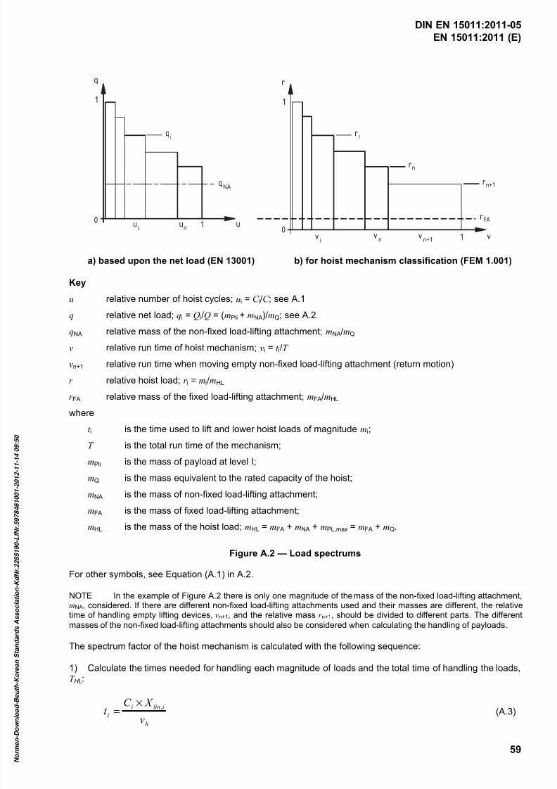
7/25/2019 DIN en 15011-2011 - Cranes - Bridge and Gantry Cranes
http://slidepdf.com/reader/full/din-en-15011-2011-cranes-bridge-and-gantry-cranes 61/95
EN 15011:2011 (E)
59
q
1
qi
0 ui
un 1
qNA
u
r
1
0
ri
rn
rn+1
rFA
vi
vn 1 vv
n+1
a) based upon the net load (EN 13001) b) for hoist mechanism classification (FEM 1.001)
Key
u relative number of hoist cycles; ui = C i/C ; see A.1
q relative net load; qi = Qi/Q = (mPli + mNA)/mQ; see A.2
qNA relative mass of the non-fixed load-lifting attachment; mNA/mQ
v relative run time of hoist mechanism; vi = t i/T
vn+1 relative run time when moving empty non-fixed load-lifting attachment (return motion)
r relative hoist load; r i = mi/mHL
r FA relative mass of the fixed load-lifting attachment; mFA/mHL
where
t i is the time used to lift and lower hoist loads of magnitude mi;
T is the total run time of the mechanism;
mPli is the mass of payload at level I;
mQ is the mass equivalent to the rated capacity of the hoist;
mNA is the mass of non-fixed load-lifting attachment;
mFA is the mass of fixed load-lifting attachment;
mHL is the mass of the hoist load; mHL = mFA + mNA + mPL,max = mFA + mQ.
Figure A.2 — Load spectrums
For other symbols, see Equation (A.1) in A.2.
NOTE In the example of Figure A.2 there is only one magnitude of the mass of the non-fixed load-lifting attachment,mNA, considered. If there are different non-fixed load-lifting attachments used and their masses are different, the relativetime of handling empty lifting devices, vn+1, and the relative mass r n+1, should be divided to different parts. The different
masses of the non-fixed load-lifting attachments should also be considered when calculating the handling of payloads.
The spectrum factor of the hoist mechanism is calculated with the following sequence:
1) Calculate the times needed for handling each magnitude of loads and the total time of handling the loads,T HL:
h
ilini
iv
X C t
,×= (A.3)
DIN EN 15011:2011-05
7/25/2019 DIN en 15011-2011 - Cranes - Bridge and Gantry Cranes
http://slidepdf.com/reader/full/din-en-15011-2011-cranes-bridge-and-gantry-cranes 62/95
EN 15011:2011 (E)
60
∑=
=n
i
i HL t T 1
(A.4)
where
vh is the rated hoisting speed;
X lin is the (h1+h2)i ; see A.3.
2) Estimate the time needed for return motions of the work cycles with empty lifting devices. If the hookpaths are same without loads as with the loads (h1 + h2 in A.3), the time needed for all return motions, T r , isequal to T HL. T r may also be smaller or larger than T HL, if the return path is shorter or longer. Total run time ofthe mechanism is then T = T HL + T r .
If some motion times t i and T r can be reduced by using higher speeds for small loads, these reductions of
times shall not be considered in the classification of the hoists and in the determination of classificationparameters of the crane use, as the final goal is to count the actual stress cycles. The stress cycles in hoist
ropes and other hoist mechanism components depend on the hoisting distances, and not directly on time usedfor motions.
3) Calculate the relative parameters appearing in Figure A.2b) as follows:
;T
t v i
i = T
T v r
n =+1 (A.5)
; HL
PLi NA FAi
m
mmmr
++=
HL
NA FAn
m
mmr
+=+1 (A.6)
4) Calculate the load spectrum factor of the hoist mechanism.
∑+
=
×=1
1
3n
i
iim r vk (A.7)
Examples of relations of k Q and k m are given in A.4.4.
A.4.3 Determination of the class of mechanism of the actual use
Referring to the definitions of ISO 4301-1 determine:
a) the class of utilization (T0 to T9) on the basis of T ;
b) the load spectrum class (L1 to L4) on the basis of k m;
c) the class of mechanism (M1 to M8) on the basis of T- and L-classes.
Select a hoist considering the determined class of the intended use.
A.4.4 Examples of relations of load spectrum factors
Assuming the following:
mFA is 3 % of mQ;
mNA = 0;
DIN EN 15011:2011-05

7/25/2019 DIN en 15011-2011 - Cranes - Bridge and Gantry Cranes
http://slidepdf.com/reader/full/din-en-15011-2011-cranes-bridge-and-gantry-cranes 63/95
EN 15011:2011 (E)
61
T HL = T r ; so vn+1 = 0,50;
q1 = 1 and u1 = 0,05;
relative load distribution is approximately linear (sloping down);
hoisting distances are equal at all load levels,
the load spectrum factor of the hoist mechanism and the net load spectrum factor have the followingrelationships, for example:
kQ = 0,062 4 0,118 0,240 0,330 0,485 0,634 0,997
k m = 0,032 6 0,062 5 0,125 0,171 0,248 0,322 0,499
DIN EN 15011:2011-05
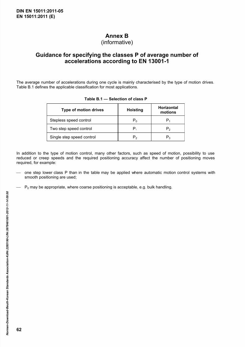
7/25/2019 DIN en 15011-2011 - Cranes - Bridge and Gantry Cranes
http://slidepdf.com/reader/full/din-en-15011-2011-cranes-bridge-and-gantry-cranes 64/95
EN 15011:2011 (E)
62
Annex B(informative)
Guidance for specifying the classes P of average number of
accelerations according to EN 13001-1
The average number of accelerations during one cycle is mainly characterised by the type of motion drives.Table B.1 defines the applicable classification for most applications.
Table B.1 — Selection of class P
Type of motion drives HoistingHorizontalmotions
Stepless speed control P0 P1
Two step speed control P1 P2
Single step speed control P2 P3
In addition to the type of motion control, many other factors, such as speed of motion, possibility to usereduced or creep speeds and the required positioning accuracy affect the number of positioning movesrequired, for example:
one step lower class P than in the table may be applied where automatic motion control systems withsmooth positioning are used;
P0 may be appropriate, where coarse positioning is acceptable, e.g. bulk handling.
DIN EN 15011:2011-05
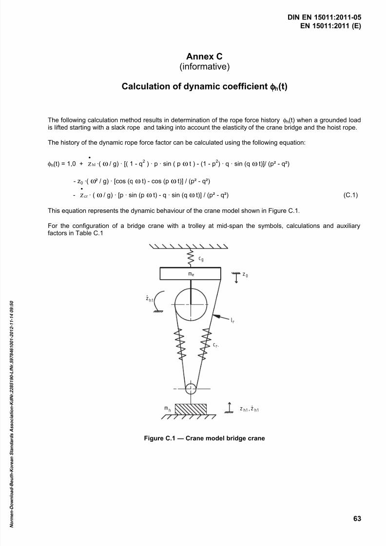
7/25/2019 DIN en 15011-2011 - Cranes - Bridge and Gantry Cranes
http://slidepdf.com/reader/full/din-en-15011-2011-cranes-bridge-and-gantry-cranes 65/95
EN 15011:2011 (E)
63
Annex C(informative)
Calculation of dynamic coefficient φφφφh(t)
The following calculation method results in determination of the rope force history φh(t) when a grounded loadis lifted starting with a slack rope and taking into account the elasticity of the crane bridge and the hoist rope.
The history of the dynamic rope force factor can be calculated using the following equation:
φh(t) = 1,0 + hlz•
·( ω / g) · [( 1 - q2 ) · p · sin ( p ω t ) - (1 - p
2) · q · sin (q ω t)]/ (p² - q²)
- z0 ·( ω ² / g) · [cos (q ω t) - cos (p ω t)] / (p² - q²)
- cr z• · ( ω / g) · [p · sin (p ω t) - q · sin (q ω t)] / (p² - q²) (C.1)
This equation represents the dynamic behaviour of the crane model shown in Figure C.1.
For the configuration of a bridge crane with a trolley at mid-span the symbols, calculations and auxiliaryfactors in Table C.1
cg
me z 0
zh1
cr
lr
,
mh z ,h1 z h1.
.
Figure C.1 — Crane model bridge crane
DIN EN 15011:2011-05
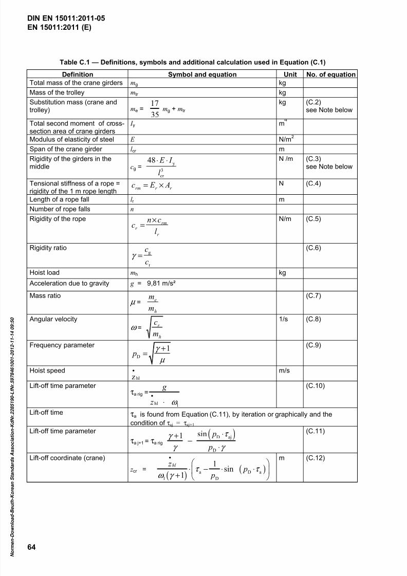
7/25/2019 DIN en 15011-2011 - Cranes - Bridge and Gantry Cranes
http://slidepdf.com/reader/full/din-en-15011-2011-cranes-bridge-and-gantry-cranes 66/95
EN 15011:2011 (E)
64
Table C.1 — Definitions, symbols and additional calculation used in Equation (C.1)
Definition Symbol and equation Unit No. of equation
Total mass of the crane girders mg kg Mass of the trolley mtr kg Substitution mass (crane andtrolley) me =
35
17 mg + mtr
kg (C.2)see Note below
Total second moment of cross-section area of crane girders
I y m
Modulus of elasticity of steel E N/m2
Span of the crane girder l cr m Rigidity of the girders in themiddle cg =
y
3
cr
48 E I
l
⋅ ⋅
N /m (C.3)see Note below
Tensional stiffness of a rope =rigidity of the 1 m rope length
r r rm A E c ×= N (C.4)
Length of a rope fall l r m Number of rope falls n
Rigidity of the rope
r
rmr
l
cnc
×=
N/m (C.5)
Rigidity ratiog
r
c
cγ =
(C.6)
Hoist load mh kg
Acceleration due to gravity g = 9,81 m/s²
Mass ratio
µ =h
em
m
(C.7)
Angular velocity ω =
h
r
m
c
1/s (C.8)
Frequency parameter
D
1 p
γ
µ
+=
(C.9)
Hoist speedhlz
•
m/s
Lift-off time parameter τa rig =
hl l
g
z ω
•
⋅
(C.10)
Lift-off time τa is found from Equation (C.11), by iteration or graphically and the
condition of τaj = τaj+1 Lift-off time parameter
τa j+1 = τa rig ( )D aj
D
sin1 p
p
τ γ
γ γ
⋅+−
⋅
(C.11)
Lift-off coordinate (crane)
z cr =( )
( )a D a
l D
1sin
1
hl z p
pτ τ
ω γ
•
⋅ − ⋅ ⋅
+
m (C.12)
DIN EN 15011:2011-05
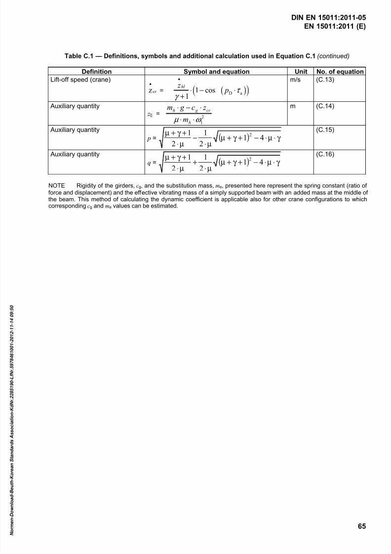
7/25/2019 DIN en 15011-2011 - Cranes - Bridge and Gantry Cranes
http://slidepdf.com/reader/full/din-en-15011-2011-cranes-bridge-and-gantry-cranes 67/95
EN 15011:2011 (E)
65
Table C.1 — Definitions, symbols and additional calculation used in Equation C.1 (continued)
Definition Symbol and equation Unit No. of equation
Lift-off speed (crane)
cr z•
= ( )( )D a1 cos
1
hl z p τ
γ
•
⋅ − ⋅
+
m/s (C.13)
Auxiliary quantity z 0 =
2
1ω µ ⋅⋅
⋅−⋅
h
cr g h
m
z c g m
m (C.14)
Auxiliary quantity p = ( ) γ ⋅µ⋅−+γ +µ
µ⋅−
µ⋅
+γ +µ41
2
1
2
1 2
(C.15)
Auxiliary quantity q = ( ) γ ⋅µ⋅−+γ +µ
µ⋅+
µ⋅
+γ +µ41
2
1
2
1 2
(C.16)
NOTE Rigidity of the girders, cg, and the substitution mass, me, presented here represent the spring constant (ratio of
force and displacement) and the effective vibrating mass of a simply supported beam with an added mass at the middle ofthe beam. This method of calculating the dynamic coefficient is applicable also for other crane configurations to whichcorresponding cg and me values can be estimated.
DIN EN 15011:2011-05

7/25/2019 DIN en 15011-2011 - Cranes - Bridge and Gantry Cranes
http://slidepdf.com/reader/full/din-en-15011-2011-cranes-bridge-and-gantry-cranes 68/95
EN 15011:2011 (E)
66
Annex D(normative)
Loads caused by skewing
D.1 Assumptions for simplified calculating methods
The calculating methods given in this annex are simplified methods based upon the following:
NOTE The statements given for a crane and its tracks are applicable also for a trolley and its tracks.
The front guide means (roller or wheel flange) of the crane contacts the rail in the skew angle α while thecrane is travelling.
a) Method RIGID:
Crane and track are represented completely rigidly. A linear form of the friction slip relationship regarding
to α is allowed. The linear form is not allowed if µ 0 < 0,3 is used.
b) Method FLEXIBLE:
The frame is represented flexibly. The carriages may be represented rigidly. A linear form of the frictionslip relationship is not allowed. The change of the wheel loads due to warping of the frame may beneglected.
For both methods the following apply:
The position of the trolley is located in such a way that the maximum skewing forces are computed. This isusually a location on the opposite side of span in relation to the side with uncoupled drives. In cases of amechanically coupled drives the trolley is set in a manner to provide equal loading on the drive wheels, usuallymid crane span. Electrically coupled drives are considered to be uncoupled.
These methods assume no accelerations, even horizontal crane track, all angles are small and that thegeometrical tolerances are ignored.
D.2 Calculation of skewing forces by method RIGID
D.2.1 Calculation model
Procedure: (see Figure D.1) Select a travel direction. Assign a number j = 1, 2, …, n to each wheel. Calculatethe sums S , S d and S dd with Equation (D.1). Calculate the intermediate value b with the Equation (D.2a)). Theforces Y j in the centre of wheel contact and the force Y F at the guide means are derived from Equation (D.3).
a) ∑= j Z S b) j jd d Z S ∑= c)2
j jdd d Z S ∑= (D.1)
a)2l W S
S b
dd
d
+= b) )1( 250
0
σ µ µ −−= e f (D.2)
a) )bd ( Z Y j j f j −= 1 µ b) ∑=−= jd f F Y )bS S ( Y µ (D.3)
where
DIN EN 15011:2011-05
7/25/2019 DIN en 15011-2011 - Cranes - Bridge and Gantry Cranes
http://slidepdf.com/reader/full/din-en-15011-2011-cranes-bridge-and-gantry-cranes 69/95
EN 15011:2011 (E)
67
f µ is the friction slip coefficient regarding the skewing angle , with α σ = in radians according
to 5.2.1.4.3;
j Z is the vertical wheel force of wheel j , ( j = 1, 2, …, n with n = number of wheels). See
explanation below;
jd is the distance in the travel direction from the front guide means to the wheel j (d j will be
negative for wheels which run ahead of the front guide means);
W is set to W = 0, if shaft coupling is not present. Otherwise consider D.2.3;
l is the span of crane. Only required if 0≠W .
Z j is the actual vertical wheel force for wheels where the bearing arrangement transfers horizontal forces. Z j is
set to zero for wheels where the bearing arrangement does not transfer horizontal forces.
Result values:
jY is the lateral force at the contact point of wheel j ;
F Y is the lateral force at the guide means.
For a crane with four wheels, flange guide, without shaft coupling ( 0=W ) and wheel numbers j according
to Figure D.1a) Equations (D.1) to (D.3) can be reduced to:
a) 11 Z Y f µ = b) 032 == Y Y c) 44 Z Y f µ = d) 41 Y Y Y F += (D.4)
D.2.2 Shaft coupling
If wheels of the crane are connected between the carriages by shafts, the skewing forces increase. Thelargest skewing forces are computed, if the wheel loads for both wheels of a shaft have the same value.
Procedure: (see Figure D.1e)) Calculate the resulting wheel force W i of each shaft i , by Equation (D.5a)). Addup the W i to W , by Equation (D.5b)). The value W is required for Equation (D.2a)). The force X i of eachindividual shaft is obtained from Equation (D.5c)).
a)
ii
iii
Z Z
Z Z W
21
21
+= b) ∑= iW W c) i f i lbW X µ = (D.5)
where
i Z 1 is the wheel load of the first wheel of shaft i ; ( 01 >i Z ); ( m ,i K1= with m = number of
shafts);
i Z 2 is the wheel load of the second wheel of shaft i ; 02 >i Z ;
l is the span of crane.
If shaft coupling exists, the position of the trolley should be set in a manner to have equal wheel loads (usually
middle of the crane span).
DIN EN 15011:2011-05

7/25/2019 DIN en 15011-2011 - Cranes - Bridge and Gantry Cranes
http://slidepdf.com/reader/full/din-en-15011-2011-cranes-bridge-and-gantry-cranes 70/95
EN 15011:2011 (E)
68
D.2.3 Examples
a)b)
e)
c)
z x
j 3
d = 1m2,3
j 4
Y F
j 2
3
5
j 1
Y FP
d)
Key
1 rigid structure 2 direction of rail 3 trolley 4 shaft coupling 5 articulation
Figure D.1 — Cranes and 3-wheel trolley
Vectors j 1 to j 4 represent both wheel force components Y j and Z j ; j = 1 to 4.
a) Figure D.1a): Bridge crane with flange guiding.
With Equations (D.1) to (D.3) and 5.2.1.4.3: 25,0= f µ ; N10=S ; Nm5=d S ;2 Nm5=dd S ;
-1m1=b ; N25,1= F Y ; { } N10025,04,3,2,1 =Y .
Or directly with Equation (D.4): { } N10025,04,3,2,1 =Y ; N25,1= F Y
b) Figure D.1b): Bridge crane with guide rollers and with and without shaft coupling.
Without shaft coupling: 25,0= f µ ; N4=S ; Nm3=d S ;2 Nm5,2=dd S ;
-1m2,1=b ;
N1,0= F Y ; { } N1,005,005,01,04,3,2,1 −−=Y .
DIN EN 15011:2011-05
7/25/2019 DIN en 15011-2011 - Cranes - Bridge and Gantry Cranes
http://slidepdf.com/reader/full/din-en-15011-2011-cranes-bridge-and-gantry-cranes 71/95
EN 15011:2011 (E)
69
With one shaft coupling 1W (Figure D.1e)): N5,01 =W ; N5,0=W ;-1m057,0=b ; N96,0= F Y ;
{ } N24,024,024,024,04,3,2,1 =Y ; N071,01 = X .
With two shaft couplings 1W and 2W : { } N5,05,02,1 =W ; N1=W ;-1m029,0=b ; N980 ,Y F = ;
{ } N25,024,024,025,04,3,2,1 =Y ; { } N036,0036,02,1 = X .
c) Figure D.1c): Trolley with three wheels. 158,0= f µ ; kN118=S ; kNm59=d S ;
2kNm25,44=dd S ;-1m33,1=b ; kN3,6= F Y ; { }kN1,35,17,43,2,1 −=Y .
d) Figure D.1d): Gantry crane with hinged leg. 25,0= f µ . Carriage of hinged leg: { } N05,02,1 =Y ;
N5,0= FP Y . Carriage of fixed leg: { } N25,004,3 =Y ; N25,0= F Y .
D.2.4 Notes
Where W = 0 structures with more than two rails can be calculated with the method above.
Derivation of equations for Method RIGID:
Equations (D.1) to (D.3) can be derived from D.3.2, Equations (D.6) to (D.11). All j s are set to 0= j s . The
friction slip relationship is linear form regarding the skew angle α : α σ µ α σ α µ σ µ f f f == )()( .
Equation (D.7) changes to α σ µ j j f j Z Y = . If Equation (D.6) is inserted into this expression a part of it can
be resumed to ( ) b x −=&& α α . Shaft coupling causes longitudinal slip xl dxd l x &&α α σ == . The forces
α σ µ σ µ W W X x f x f W
== )( resulting from longitudinal slip cause, with the span l , the moment
W W X l M = . If W X is replaced by the expression given before, also here a part can be resumed
to ( ) b x −=&& α α . Equation (D.10) is extended with the influence of the shaft coupling: ∑+= j jW d Y M 0 .
Therein only b is unknown and after transformation b can be calculated as shown in Equation (D.2).
For further information, see Bibliography.
D.3 Calculation of skewing forces by method FLEXIBLE
D.3.1 General
The following calculation method represents the frame as flexible. The carriage is represented as rigid. Thisapproach is of significance for gantry cranes with single side guidance means.
D.3.2 Calculation model
Figure D.2a) shows the model characteristics with a four-wheel crane with guide rollers as example. Theportal is flexible. Both carriages are assumed as rigid. The skewing angle α is assigned to the guided
carriage. The leading guide roller is in contact with the rail. Figure D.2b) shows the forces. The eccentrically
acting force F Y affects with the moment the non-guided carriage. According to the flexibility of the frame,
the non-guided carriage’s skewing angle is increased by α ∆ . All angles are small.
DIN EN 15011:2011-05
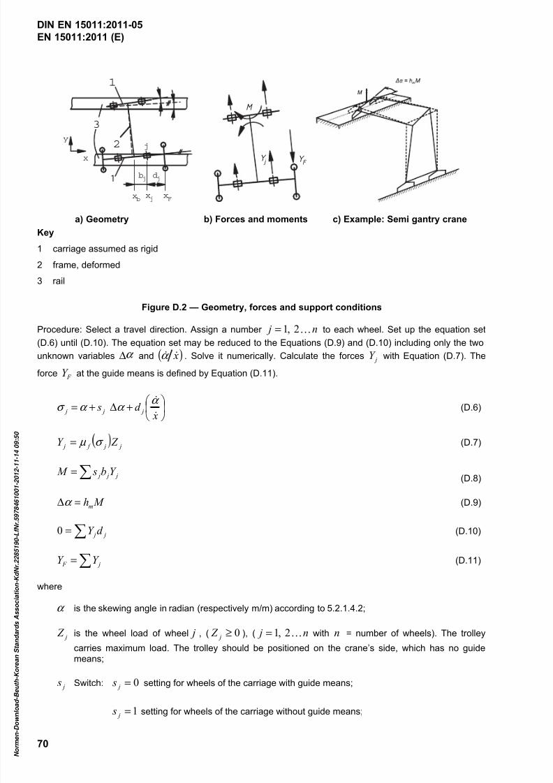
7/25/2019 DIN en 15011-2011 - Cranes - Bridge and Gantry Cranes
http://slidepdf.com/reader/full/din-en-15011-2011-cranes-bridge-and-gantry-cranes 72/95
EN 15011:2011 (E)
70
3
2
1
xb
x
y
xj
xF
dj
bj
j
j Y
M
F Y
a) Geometry b) Forces and moments c) Example: Semi gantry crane
Key
1 carriage assumed as rigid
2 frame, deformed
3 rail
Figure D.2 — Geometry, forces and support conditions
Procedure: Select a travel direction. Assign a number n j K2,1= to each wheel. Set up the equation set
(D.6) until (D.10). The equation set may be reduced to the Equations (D.9) and (D.10) including only the two
unknown variables ∆ and ( ) x&&α . Solve it numerically. Calculate the forces jY with Equation (D.7). The
force F Y at the guide means is defined by Equation (D.11).
+∆+= xd s j j j&
&α
α α σ (D.6)
j j f j Z Y σ µ = (D.7)
∑= j j j Y b s M (D.8)
M hm=∆α (D.9)
j jd Y ∑=0 (D.10)
∑= j F Y Y (D.11)
where
α is the skewing angle in radian (respectively m/m) according to 5.2.1.4.2;
j Z is the wheel load of wheel j , ( 0≥ j Z ), ( n j K2,1= with n = number of wheels). The trolley
carries maximum load. The trolley should be positioned on the crane’s side, which has no guidemeans;
j s Switch: 0= j s setting for wheels of the carriage with guide means;
1= j s setting for wheels of the carriage without guide means;
DIN EN 15011:2011-05

7/25/2019 DIN en 15011-2011 - Cranes - Bridge and Gantry Cranes
http://slidepdf.com/reader/full/din-en-15011-2011-cranes-bridge-and-gantry-cranes 73/95
EN 15011:2011 (E)
71
M is the moment turning the floating end carriage by forces Y j applied to the wheels of that carriage;
M h is the flexibility of the portal in angle per moment (e.g. rad/Nm). See Figure D.2c): Fixed support at
the carriage with guide means. Floating support and an external moment acting at the unguidedcarriage. (Find out the change of angle with a statics program, or manually in simple cases.);
jd j F x x −= Distance in travel direction from the front guide means to wheel j ( jd will be negative for
wheels which run ahead of the front guide means);
jb b j x x −= Distance in travel direction from wheel j to the neutral line b x . (This line is neutral
concerning the bending around the plumb line, see the figure in Example D.3.3. b x marks the
coordinate where a single force F y applied to the floating carriage will not result in any change of
∆ .) ( jb will be negative for wheels which run behind the neutral line).
The friction slip relationship is according to 5.2.1.4.3:
( ) j j f
je σ µ σ µ σ
sgn1)(250
0 ⋅
−=
−
(D.12)
where
µf ( σ j ) is the slip coefficient;
µ0 is the adhesion factor equal to 0,30;
e is the base of natural logarithms, 2,718;
σ is the slip factor;
sgn is the signum function = ( ) = x sgn { 1− for 0< x ; 0 for 0= x ; 1 for 0> x }.
Calculation values:
jσ is the lateral slip of the wheel j ;
)( j f σ µ is the friction coefficient of wheel j by lateral slip jσ according to 5.2.1.4.3;
α ∆ is the additional skewing angle due to flexible deformation;
M is the moment between the portal and the unguided carriage;
x&&α is the portal turning speed per travel speed ( 0> x& ). A separate value for x& is not required;
jY is the lateral force of wheel j ;
F Y is the force at guide means.
DIN EN 15011:2011-05
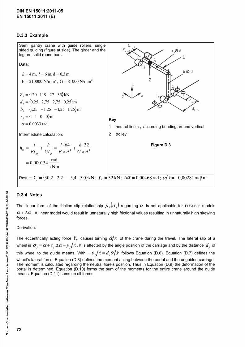
7/25/2019 DIN en 15011-2011 - Cranes - Bridge and Gantry Cranes
http://slidepdf.com/reader/full/din-en-15011-2011-cranes-bridge-and-gantry-cranes 74/95
EN 15011:2011 (E)
72
D.3.3 Example
Semi gantry crane with guide rollers, singlesided guiding (figure at side). The girder and theleg are solid round bars.
Data:
{ }
{ }
{ }
{ }
rad0033,0
m0011
m25,125,125,125,1
m25,075,275,225,0
kN3527119120
N/mm81000G , N/mm210000E
m3,0dm,6 m,4
22
=
=
−−=
=
=
==
===
α
j
j
j
j
s
b
d
Z
l h
Intermediate calculation:
kNm
rad000134,0
326444
=
⋅+
⋅=+=
d G
h
d E
l
GI
h
EI
l h
pax
mπ π
1
2
b2,3
b1,4
d1,4
d2,3
z
y x
j4
j3
j2
j1
dh,
dl,
Key1 neutral line b x according bending around vertical
2 trolley
Figure D.3
Result: { }kN0,54,52,22,30 −= jY ; kN32= F Y ; rad00468,0=∆ ; mrad0,00281−= x&&α
D.3.4 Notes
The linear form of the friction slip relationship j f σ µ regarding α is not applicable for FLEXIBLE models
∆+ . A linear model would result in unnaturally high frictional values resulting in unnaturally high skewing
forces.
Derivation:
The eccentrically acting force F Y causes turning x&&α of the crane during the travel. The lateral slip of a
wheel is x y s j j j &&−∆+= α α σ . It is affected by the angle position of the carriage and by the distance jd of
this wheel to the guide means. With xd x y j j &&&& α =− follows Equation (D.6). Equation (D.7) defines the
wheel’s lateral force. Equation (D.8) defines the moment acting between the portal and the unguided carriage.The moment is calculated regarding the neutral fibre’s position. Thus in Equation (D.9) the deformation of theportal is determined. Equation (D.10) forms the sum of the moments for the entire crane around the guidemeans. Equation (D.11) sums up all forces.
DIN EN 15011:2011-05
7/25/2019 DIN en 15011-2011 - Cranes - Bridge and Gantry Cranes
http://slidepdf.com/reader/full/din-en-15011-2011-cranes-bridge-and-gantry-cranes 75/95
EN 15011:2011 (E)
73
Annex E(informative)
Calculation of stall load factor for indirect acting lifting force limiter
Indirect acting lifting force limiters measure the load using a sensor and override the controls to preventexcessive loading by bringing the motion to rest. Evaluation of the measured values and filtering ofinterference signals require time and act as a triggering delay. An additional time delay takes place before thebraking torque is applied.
The stall load factor φ IAL for indirect acting lifting force limiters can be calculated as follows:
( ) g mt
t t vC H st
br IALh H IAL ⋅
++⋅⋅+⋅= /)2
(05.1 2φ φ (E.1)
where
φ 2 is the φ 2 -factor for load combination A1; see 5.2.1.3.2;
vh is the maximum hoisting speed at which the indirect acting force limiter may be
triggered, in metres per second;
mH is the mass of the hoist load, in kilograms;
t IAL is the response-time of the indirect acting lifting force limiter, in seconds;
t br is the reaction time of the braking, in seconds;
t st is the time to stop the mechanism in stall condition by effects of the braking andincreasing rope force, in seconds;
C H is elasticity factor of crane structure and rope system at the load suspension point, innewtons per metre.
The term 1,05 φ 2 represents the triggering point of immediate stop of the indirect acting limiter, see 5.5.1.2.
The assumed, simplified triggering and stopping process is illustrated in Figure E.1.
DIN EN 15011:2011-05

7/25/2019 DIN en 15011-2011 - Cranes - Bridge and Gantry Cranes
http://slidepdf.com/reader/full/din-en-15011-2011-cranes-bridge-and-gantry-cranes 76/95
EN 15011:2011 (E)
74
t
D
A B C
t stt br
t IAL
V
Key
A triggering happens C braking is applied
B braking receives the stopping instruction D the hoist mechanism has stopped
Figure E.1 — Hoist mechanism speed (v) by time (t) at immediate stop with indirect acting lifting forcelimiter
DIN EN 15011:2011-05

7/25/2019 DIN en 15011-2011 - Cranes - Bridge and Gantry Cranes
http://slidepdf.com/reader/full/din-en-15011-2011-cranes-bridge-and-gantry-cranes 77/95
EN 15011:2011 (E)
75
Annex F(informative)
Local stresses in wheel supporting flanges
F.1 General
When trolleys travel on the girder flanges of a girder, irrespective of the girder support arrangement, flangebending stresses occur as secondary stresses in the area of the point of application of the wheel load F .
Formulae and coefficients are given for two types of main girders:
a) in F.2: main girder as I-beam;
b) in F.3: main girder as box girder.
When determining the stresses in accordance with EN 13001-2:2004+A3:2009, Table 10 and in the proof offatigue strength, the local stresses shall be combined with the global stresses. In the load combinations A, Band C (see EN 13001-2:2004+A3:2009, Table 10) and in the proof of fatigue strength (load combinations A),the local stresses in the plates and shall be multiplied by 0,75 before combining with the global stresses.
If the wheel loads F are not symmetrical, the local stresses are calculated with the maximum wheel load andthe relevant distance i. In addition to these flange bending stresses and the main stresses, torsion stressesfrom the resulting non-symmetrical load application point shall be calculated in the girder cross section.
NOTE The local stresses can be reduced by factor 0,75 because of the extra plastic bending capacity of the flange
plate or extra plastic tension capacity of the web.
In fatigue analysis the effect of local stress can be reduced, because the fatigue strength in bending of a plate is typically
30 % to 60 % higher than in tension, for the same joint or detail.
F.2 Local stresses in wheel supporting flanges (main girder as I-beam)
These stresses act in the two directions x and y as σFx and σFy (see Figures F.1a) and b)).
The stresses are calculated with the help of the following equations:
( ) 2
f
xFxtFc λ =σ (F.1)
( )2
f
yFyt
Fc λ =σ (F.2)
These local stresses shall be multiplied by 0,75 and combined with the global stresses both in static andfatigue analysis.
DIN EN 15011:2011-05
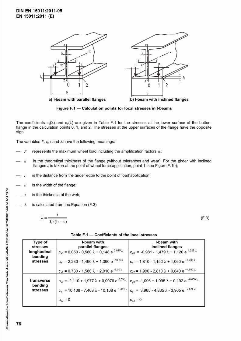
7/25/2019 DIN en 15011-2011 - Cranes - Bridge and Gantry Cranes
http://slidepdf.com/reader/full/din-en-15011-2011-cranes-bridge-and-gantry-cranes 78/95
EN 15011:2011 (E)
76
0 1 2
x
z
s
y yx FF ii
ztf
b
0 1 2
x
z
s
y yx FF ii
tf
b
z
a) I-beam with parallel flanges b) I-beam with inclined flanges
Figure F.1 — Calculation points for local stresses in I-beams
The coefficients cx(λ ) and cy(λ ) are given in Table F.1 for the stresses at the lower surface of the bottomflange in the calculation points 0, 1, and 2. The stresses at the upper surfaces of the flange have the oppositesign.
The variables F , t f , i and λ have the following meanings:
F represents the maximum wheel load including the amplification factors φi;
t f is the theoretical thickness of the flange (without tolerances and wear). For the girder with inclinedflanges t f is taken at the point of wheel force application, point 1, see Figure F.1b);
i is the distance from the girder edge to the point of load application;
b is the width of the flange;
s is the thickness of the web;
λ is calculated from the Equation (F.3).
s)0,5(b
iλ
−= (F.3)
Table F.1 — Coefficients of the local stresses
Type ofstresses
I-beam withparallel flanges
I-beam withinclined flanges
longitudinal cx0 = 0,050 - 0,580 λ + 0,148 e3,015 λ cx0 = -0,981 - 1,479 λ + 1,120 e
1,322 λ bendingstresses cx1 = 2,230 - 1,490 λ + 1,390 e
-18,33 λ cx1 = 1,810 - 1,150 λ + 1,060 e –7,700 λ
cx2 = 0,730 - 1,580 λ + 2,910 e-6,00 λ cx2 = 1,990 - 2,810 λ + 0,840 e
–4,690 λ
transverse cy0 = -2,110 + 1,977 λ + 0,0076 e6,53 λ cy0 = -1,096 + 1,095 λ + 0,192 e
–6,000 λ bendingstresses cy1 = 10,108 - 7,408 λ - 10,108 e
-1,364 λ cy1 = 3,965 - 4,835 λ - 3,965 e –2,675 λ
cy2 = 0 cy2 = 0
DIN EN 15011:2011-05
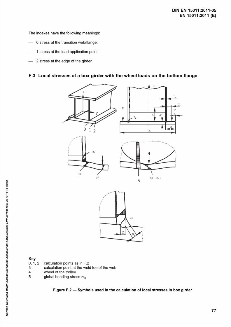
7/25/2019 DIN en 15011-2011 - Cranes - Bridge and Gantry Cranes
http://slidepdf.com/reader/full/din-en-15011-2011-cranes-bridge-and-gantry-cranes 79/95
EN 15011:2011 (E)
77
The indexes have the following meanings:
0 stress at the transition web/flange;
1 stress at the load application point;
2 stress at the edge of the girder.
F.3 Local stresses of a box girder with the wheel loads on the bottom flange
0 1 2
x
y
z
3
FF
i
b
a
z
tw
d
t f h
z3
y0
y1 x1, x2,
4
5
z3
paw
Key0, 1, 2 calculation points as in F.23 calculation point at the weld toe of the web4 wheel of the trolley
5 global bending stress σxg
Figure F.2 — Symbols used in the calculation of local stresses in box girder
DIN EN 15011:2011-05
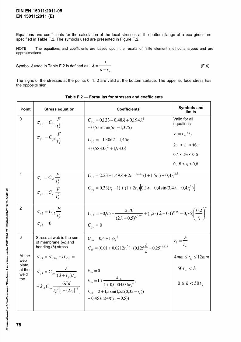
7/25/2019 DIN en 15011-2011 - Cranes - Bridge and Gantry Cranes
http://slidepdf.com/reader/full/din-en-15011-2011-cranes-bridge-and-gantry-cranes 80/95
EN 15011:2011 (E)
78
Equations and coefficients for the calculation of the local stresses at the bottom flange of a box girder arespecified in Table F.2. The symbols used are presented in Figure F.2.
NOTE The equations and coefficients are based upon the results of finite element method analyses and areapproximations.
Symbol λ used in Table F.2 is defined as
wt a
i
−=λ (F.4)
The signs of the stresses at the points 0, 1, 2 are valid at the bottom surface. The upper surface stress hasthe opposite sign.
Table F.2 — Formulas for stresses and coefficients
Point Stress equation Coefficients Symbols andlimits
0
200
200
f
y y
f
x x
t
F C
t F C
=
=
σ
σ
)375,15arctan(5,0
194,048,0123,0 20
−−++=
t
x
r
C λ λ
λ 933,15833,0
45,13067,1
2
0
++
−−=
t
t y
r
r C
Valid for allequations
f wt t t r /=
2a < b < 16a
0,1 < i / a < 0,5
0,15 < r t < 0,8
1
211
211
f
y y
f x x
t
F C
t
F
C
=
=
σ
σ
5,233,18
1 4,0)5,11(249.123.2 t t x r r eC +++−= − λ λ
[ ])4,04,3sin(4,03,0)21()1(33,0 2
1 t t t y r r r C ++++−= λ λ
2
02
222
=
=
y
f
x xt
F C
σ
σ
4
25,0
2
2,0)76,0)1,0(2,1(
)5,02(
70,295,0
333,0
−−⋅+
++−=
t r x
r C
t
λ λ
02 = yC
3
At thewebplate,at theweldtoe
Stress at web is the sumof membrane (m) andbending (b) stress
=+= b z m z z 333 σ σ σ
( )[ ]33
3
21
6
)(
−+
+
+=
t w
zb zh
w f
zm z
r t
Fd C k
t t d
F C σ
))5,0(4sin(45,0
))35,0(5,1sin(5,12
,0004536,01
1
0
)25,0125,0()0212,001,0(
8,14,0
0
3
0
125,03
2
−+
−+=
++=
=
−⋅+=
+=
t
t z
h
z
zh
zh
t zb
t zm
r
r k
r
k k
k
a
br C
r C
π
π
w
ht hr =
mmt mm w 124 ≤≤
w
w
t h
ht
500
50
<≤
<
DIN EN 15011:2011-05

7/25/2019 DIN en 15011-2011 - Cranes - Bridge and Gantry Cranes
http://slidepdf.com/reader/full/din-en-15011-2011-cranes-bridge-and-gantry-cranes 81/95

7/25/2019 DIN en 15011-2011 - Cranes - Bridge and Gantry Cranes
http://slidepdf.com/reader/full/din-en-15011-2011-cranes-bridge-and-gantry-cranes 82/95
EN 15011:2011 (E)
80
Annex G(normative)
Noise test code
G.1 General
This noise test code specifies all the information necessary to carry out efficiently and under standardizedconditions the determination, declaration and verification of the noise emission characteristics of bridge andgantry cranes.
Noise emission characteristics include emission sound pressure levels at operator's positions. Thedetermination of these quantities is necessary for:
manufacturers to declare the noise emitted;
comparing the noise emitted by machines in the family concerned;
purposes of noise control at the source at the design stage.
The use of this noise test code ensures reproducibility of the determination of the noise emissioncharacteristics within specified limits determined by the grade of accuracy of the basic noise measurementmethod used. Noise determination methods allowed by this standard are:
a calculation method (G.3) to determine the overall noise emitted by the noisiest components of thecrane.
This method shall be used systematically and the value resulting from the calculation shall be given in theinstructions for use (see 7.3.1) unless the measured values are available.
Noise caused by rail-wheel contact in travelling and noise emitted by the runway structures as well asnoise from crane power supply festoon system or conductor bars are excluded, because they may not befully in crane manufacturer's control.
This method underestimates the actual noise emission value of the crane when installed at the user'splace;
a measurement method (G.4) of the sound pressure level at the operator's position once the crane is
installed at the user's place.
This sound pressure level is not an emission sound pressure level because it includes the crane, thestructure to which the crane is fixed and the acoustic characteristics of the room or surroundings.
This method has priority over the calculated values, when the sound pressure value added by theuncertainty exceeds 70 dB(A) at a working place.
The measurement determines two values, one for hoisting and traversing and another for the travelling ofa crane. Both values shall be given in the instructions for use (see 7.3.1). For the sound pressure level atthe operator's position, both values have to be considered. The actual value may be higher than thebiggest of them, when there is a situation where hoisting, traversing and travelling occur at the sametime.
For the cranes that have an A-weighted emission sound pressure level at the operator’s position higher than80 dB the sound power level shall be indicated. Determination of the required values is presented in G.4.1.2.
DIN EN 15011:2011-05

7/25/2019 DIN en 15011-2011 - Cranes - Bridge and Gantry Cranes
http://slidepdf.com/reader/full/din-en-15011-2011-cranes-bridge-and-gantry-cranes 83/95
EN 15011:2011 (E)
81
The C-weighted peak emission sound pressure levels in the bridge and gantry cranes are typically so low thatthey need not to be measured and reported.
G.2 Description of machinery family
This annex is applicable to individual bridge or gantry crane in the scope of this European Standard as fullyassembled in the intended working condition including the fixed load lifting attachment.
G.3 Determination of a conventional emission sound pressure level by calculation
G.3.1 Principle of the method
The conventional emission sound pressure level at the operator's position is calculated as the summation ofthe contributions at this position of the main noise sources present on the crane. These contributions arederived from the sound power levels of these main noise sources as provided by their manufacturers.
G.3.2 Calculation
The contribution of a given noise source with A-weighted sound power level LWA is given by the followingequation:
−=
0
lg10S
S L L WA pA (G.1)
where
L pA is the resulting A-weighted sound pressure level at the operator's position;
LWA is the A-weighted sound power level of the source, in decibels; reference: 1 pW;
S = 2πr 2, where r is the distance between the considered place and the sound source;
S 0 = 1 m2.
The values of the sound power level of the components to be used in the calculation shall correspond to therated loads and speeds of the crane.
The noise sources to be taken into account in the calculation are:
hoist mechanism;
trolley traverse mechanism;
crane travelling mechanisms;
fixed load lifting attachment, when power operated.
The values shall include the noise of the electrical control cubicles and power source.
The typical locations of these noise sources are shown in Figure G.1. The operator is assumed to be in avertical plane containing the sources. For the power operated load lifting attachment the nearest normal
operating distance shall be considered.
The values of the A-weighted sound power levels and the distances r used for the calculations shall be
reported.
DIN EN 15011:2011-05

7/25/2019 DIN en 15011-2011 - Cranes - Bridge and Gantry Cranes
http://slidepdf.com/reader/full/din-en-15011-2011-cranes-bridge-and-gantry-cranes 84/95
EN 15011:2011 (E)
82
Figure G.1 — Noise sources of a bridge crane
The conventional A-weighted emission sound pressure level at a certain position under the influence ofdifferent sound sources shall be calculated by adding the sound pressure levels from the different sources inaccordance with the following equation:
= ∑
=
N
i
L
total pA pAi L
1
1,0
)( 10lg10 (G.2)
where
L pA(total) is the conventional A-weighted emission sound pressure level, i.e. the total A-weighted soundpressure level at the considered position resulting from N sources;
L pAi is the A-weighted sound pressure level resulting from sound source i ;
N is the total number of sound sources.
The uncertainty of the calculation is that with which the sound power levels of the components have beendetermined.
This calculation method does not take into account the effect of structure-borne noise and sound reflection bythe ground and therefore the calculated noise levels are usually lower than levels that would be measured.
NOTE The equation below illustrates the method for the addition of two A-weighted sound pressure levels,70 dB(A) and 72 dB(A) respectively:
)(1,721010lg10721,0701,0
)( AdB L total pa =+= ×× (G.3)
DIN EN 15011:2011-05
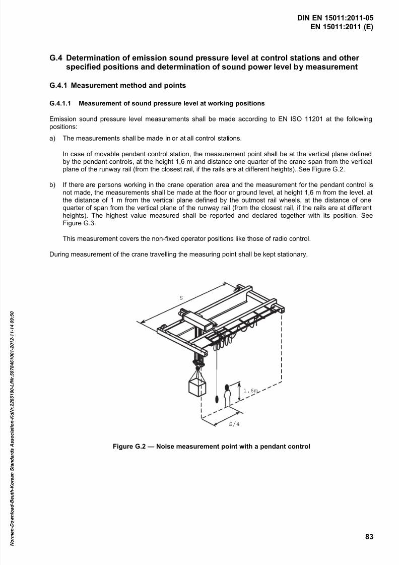
7/25/2019 DIN en 15011-2011 - Cranes - Bridge and Gantry Cranes
http://slidepdf.com/reader/full/din-en-15011-2011-cranes-bridge-and-gantry-cranes 85/95
EN 15011:2011 (E)
83
G.4 Determination of emission sound pressure level at control stations and otherspecified positions and determination of sound power level by measurement
G.4.1 Measurement method and points
G.4.1.1 Measurement of sound pressure level at working positions
Emission sound pressure level measurements shall be made according to EN ISO 11201 at the followingpositions:
a) The measurements shall be made in or at all control stations.
In case of movable pendant control station, the measurement point shall be at the vertical plane definedby the pendant controls, at the height 1,6 m and distance one quarter of the crane span from the verticalplane of the runway rail (from the closest rail, if the rails are at different heights). See Figure G.2.
b) If there are persons working in the crane operation area and the measurement for the pendant control isnot made, the measurements shall be made at the floor or ground level, at height 1,6 m from the level, atthe distance of 1 m from the vertical plane defined by the outmost rail wheels, at the distance of onequarter of span from the vertical plane of the runway rail (from the closest rail, if the rails are at differentheights). The highest value measured shall be reported and declared together with its position. SeeFigure G.3.
This measurement covers the non-fixed operator positions like those of radio control.
During measurement of the crane travelling the measuring point shall be kept stationary.
S
1,6m
S/4
Figure G.2 — Noise measurement point with a pendant control
DIN EN 15011:2011-05
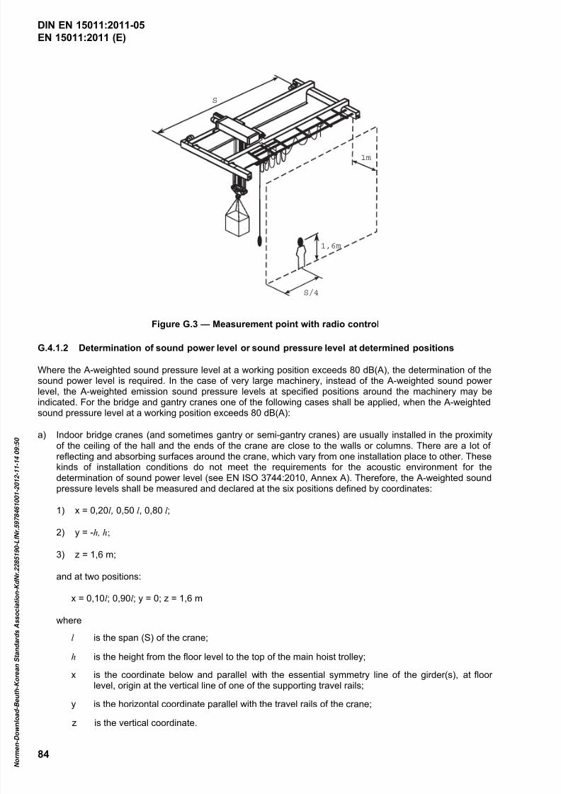
7/25/2019 DIN en 15011-2011 - Cranes - Bridge and Gantry Cranes
http://slidepdf.com/reader/full/din-en-15011-2011-cranes-bridge-and-gantry-cranes 86/95
EN 15011:2011 (E)
84
S
1,6m
1m
S/4
Figure G.3 — Measurement point with radio control
G.4.1.2 Determination of sound power level or sound pressure level at determined positions
Where the A-weighted sound pressure level at a working position exceeds 80 dB(A), the determination of thesound power level is required. In the case of very large machinery, instead of the A-weighted sound powerlevel, the A-weighted emission sound pressure levels at specified positions around the machinery may beindicated. For the bridge and gantry cranes one of the following cases shall be applied, when the A-weighted
sound pressure level at a working position exceeds 80 dB(A):
a) Indoor bridge cranes (and sometimes gantry or semi-gantry cranes) are usually installed in the proximityof the ceiling of the hall and the ends of the crane are close to the walls or columns. There are a lot ofreflecting and absorbing surfaces around the crane, which vary from one installation place to other. Thesekinds of installation conditions do not meet the requirements for the acoustic environment for thedetermination of sound power level (see EN ISO 3744:2010, Annex A). Therefore, the A-weighted soundpressure levels shall be measured and declared at the six positions defined by coordinates:
1) x = 0,20l , 0,50 l , 0,80 l ;
2) y = -h, h;
3) z = 1,6 m;
and at two positions:
x = 0,10l ; 0,90l ; y = 0; z = 1,6 m
where
l is the span (S) of the crane;
h is the height from the floor level to the top of the main hoist trolley;
x is the coordinate below and parallel with the essential symmetry line of the girder(s), at floorlevel, origin at the vertical line of one of the supporting travel rails;
y is the horizontal coordinate parallel with the travel rails of the crane;
DIN EN 15011:2011-05
z is the vertical coordinate.

7/25/2019 DIN en 15011-2011 - Cranes - Bridge and Gantry Cranes
http://slidepdf.com/reader/full/din-en-15011-2011-cranes-bridge-and-gantry-cranes 87/95
EN 15011:2011 (E)
85
The working cycle during the measurement shall be as described in G.4.3.2, a).
b) Large outdoor bridge and gantry cranes have dimensions outside the radius of 16 m. In most cases the
installation conditions do not meet requirements for the determination of sound power level. Thedetermination of the sound power level shall be replaced by the measurement and declaration of soundpressure levels in the positions determined essentially in the same way as for indoor cranes. In thisdetermination the cantilevers can be ignored, as the sound power radiated by the hoist trolley on acantilever is essentially same as on the span area. Exceptionally, in cases where a separate, fixedmachinery house is installed outside the span, e.g. on a cantilever, the length l shall be extended so thatit includes the machinery house totally. The length of traversing motion shall be extended accordingly.
The working cycle during the measurement shall be as described in G.4.3.2, a).
c) Where an outdoor gantry crane is sufficiently small and acoustic environment is sufficient, the soundpower level shall be determined in accordance with EN ISO 3744. The reference box and measuringsurface parameters shall be determined on the following principles:
1) length l 1 is the span of the crane; where fixed machineries are located outside the span, l 1 shall be
extended to include them;
2) width l 2 is the maximum distance between the outer surfaces of the vertical legs in yz-plane;
3) height l 3 is the vertical distance from the travel rail level to the top of the main hoist trolley or the
machinery house, whichever is higher.
The key microphone positions shall be on a hemisphere with radius 16 m or on a parallelepipedmeasurement surface with distance d equal to 4 m or 8 m from the reference box, depending on theacoustic environment requirements.
d) Where the A-weighted sound power levels for the hoisting and traversing motion of the hoist trolley (underloaded condition) and for the fixed load lifting attachment can be measured in a qualified acousticenvironment, those values can be declared instead of the power level of the whole crane. Duringmeasurement of the traversing, the trolley shall be running along the steel girder(s), as this represents theactual use.
NOTE 1 The travelling motion can be omitted, as it is usually so silent that an additional acoustic warning signal isneeded, or it depends on the construction of the overhead runways that is out of control of the crane manufacturer.
NOTE 2 Case d) above is typically applicable for serially manufactured hoists. The custom-built hoist trolleys are typically
individual and are not operable with load in a qualified acoustic environment before installation at the end user’s site.
G.4.2 Installation and mounting conditions
The crane shall be installed on its runway in the condition it is intended to be used excluding the sound alarmsignals which shall be disconnected during the noise measurements.
The mechanisms of the non-fixed load lifting attachments causing noise may be switched off during the noisemeasurement cycle.
NOTE Noise caused by the non-fixed load lifting attachments is the matter of the manufacturer of the equipment.
G.4.3 Operating conditions
G.4.3.1 General
In all cases, the testing position of the crane for the measurements should be so selected that the reflectionsand other environmental disturbances are minimized.
DIN EN 15011:2011-05
7/25/2019 DIN en 15011-2011 - Cranes - Bridge and Gantry Cranes
http://slidepdf.com/reader/full/din-en-15011-2011-cranes-bridge-and-gantry-cranes 88/95
EN 15011:2011 (E)
86
The load handled during the work cycles should be preferably the rated load, but in the case of difficulty to usethe rated load, a load representing the typical loads and having a mass that is at least 50 % of the rated loadmass may be used.
Measurements in enclosed cabins shall be taken with the doors and windows closed and the air-conditioning
and/or ventilating system(s) operating at midrange speed if more than two operating speeds are available. Ifonly two operating speeds are available, then the highest speed shall be used. If the air-conditioning and/orventilating systems have a recirculation and outside air position, it shall be set for outside air.
G.4.3.2 Hoisting and traversing
a) Work cycle of a crane without cantilevers
The work cycle during measurement shall be as follows:
1) Hoist the load with maximum speed at the point one quarter of span (beside the measuring point).Duration shall correspond to one half of the total lifting height.
2) Start traversing during the hoisting (about at the mid height of hoist path) and go on to the point 3/4of the span.
3) Start lowering before stopping the traversing motion and go on to the ground level.
4) Return the load to the start position in the reverse manner.
5) Where slewing of the trolley or slewing of a lifting attachment is included, it shall be operated duringtraversing.
Where there are limitations in making movements simultaneously, the cycle description shall be modifiedaccordingly.
b) Work cycle of a crane with cantilevers
The cycle shall be identical to that of a), however the hoisting shall commence at the middle point of thecantilever.
Test cycles and measurements in a) and b) shall be repeated at least three times.
The test result 1 pA L is the arithmetic mean of the measured maximum values.
G.4.3.3 Travelling
Noise measurement during crane travelling shall be made separately holding the load at the mid span of thecrane.
The measuring period shall start when the reference box reaches the stationary microphone, and it shall endwhen the other side of the reference box has passed the microphone.
NOTE The reference box is a hypothetical surface which is the smallest rectangular parallelepiped that just enclosesthe noise sources (the whole crane structure) and terminates on the reflecting plane (floor).
Test cycles and measurements shall be repeated at least three times.
The test result 2 pA L is the arithmetic mean of the measured maximum values.
DIN EN 15011:2011-05
7/25/2019 DIN en 15011-2011 - Cranes - Bridge and Gantry Cranes
http://slidepdf.com/reader/full/din-en-15011-2011-cranes-bridge-and-gantry-cranes 89/95
EN 15011:2011 (E)
87
G.5 Uncertainties
No technical data on noise emission are presently available to estimate the standard deviation ofreproducibility for the family of machinery covered by this noise test code. Therefore, the values of thestandard deviation of reproducibility stated in the basic noise emission standards may be regarded as interim
upper boundaries and used for the determination of the uncertainty K when preparing the noise declaration.Investigations requiring a joint effort of manufacturers are necessary to determine a possibly lower value ofthe standard deviation of reproducibility, which will result in a lower value of the uncertainty K . Results of such
investigations will be reflected in a future version of this standard.
G.6 Information to be recorded
Measurements shall be recorded according to EN ISO 11202:2010, Clause 12.
For the calculation method the information to be recorded is specified in EN ISO 11203:2009, Clause 7.
G.7 Information to be reported
The reports shall include the A-weighted emission sound pressure levels and the positions where they weremeasured or calculated.
Where required, the A-weighted sound power level of the crane, or sound power levels of the mechanismsduring work cycles, shall be reported. The method of determining the power levels shall be indicated.
Where the sound pressure levels in specified positions are reported (G.4.1.2, a) and b)) instead of therequired sound power level, this fact shall be reported. The acoustic environment condition shall also bereported (for guidance on description of environment, see EN ISO 3744:2010, Table A.1).
The noise values measured during crane travelling shall be reported separately from the values representingthe specified work cycle, because such values may be more strongly affected by the noise generated in therunways and the building.
In the calculation method the assumptions made for the calculation, the precise positions of sound sourcesand operator(s), the values used as sound power input data and the results of the calculations shall bereported.
G.8 Declaration and verification of noise emission values
The declaration and verification of noise emission values shall be made in accordance with EN ISO 4871.
These values shall be preferably the measured values obtained in accordance with G.4 or the calculatedvalues (G.3). Example is given in Table G.1.
The noise declaration shall be a dual number declaration as defined in EN ISO 4871, i.e. the noise emissionlevel and the uncertainty being indicated separately. It shall give the value of the A-weighted emission soundpressure level at the control stations and other specified working positions, where this exceeds 70 dB; wherethis level does not exceed 70 dB, this fact shall be indicated.
The noise declaration shall mention explicitly that noise emission values have been obtained in accordancewith this noise test code and indicate the basic standard that has been used, i.e. EN ISO 11201. The noisedeclaration shall clearly indicate any deviation(s) from this noise test code and/or from the basic standardused.
DIN EN 15011:2011-05
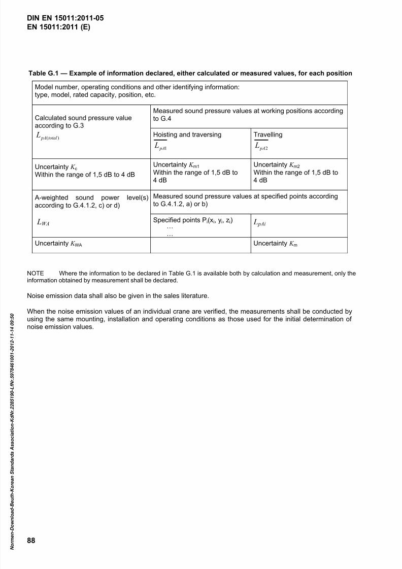
7/25/2019 DIN en 15011-2011 - Cranes - Bridge and Gantry Cranes
http://slidepdf.com/reader/full/din-en-15011-2011-cranes-bridge-and-gantry-cranes 90/95
EN 15011:2011 (E)
88
Table G.1 — Example of information declared, either calculated or measured values, for each position
Model number, operating conditions and other identifying information:type, model, rated capacity, position, etc.
Calculated sound pressure valueaccording to G.3
)(total pA L
Measured sound pressure values at working positions accordingto G.4
Hoisting and traversing
1 pA L
Travelling
2 pA L
Uncertainty K c Within the range of 1,5 dB to 4 dB
Uncertainty K m1
Within the range of 1,5 dB to4 dB
Uncertainty K m2
Within the range of 1,5 dB to4 dB
A-weighted sound power level(s)according to G.4.1.2, c) or d)
LWA
Measured sound pressure values at specified points accordingto G.4.1.2, a) or b)
Specified points Pi(xi, yi, zi)……
L pAi
Uncertainty K WA Uncertainty K m
NOTE Where the information to be declared in Table G.1 is available both by calculation and measurement, only theinformation obtained by measurement shall be declared.
Noise emission data shall also be given in the sales literature.
When the noise emission values of an individual crane are verified, the measurements shall be conducted byusing the same mounting, installation and operating conditions as those used for the initial determination ofnoise emission values.
DIN EN 15011:2011-05
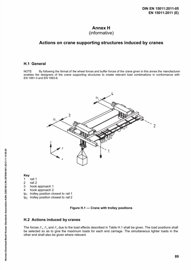
7/25/2019 DIN en 15011-2011 - Cranes - Bridge and Gantry Cranes
http://slidepdf.com/reader/full/din-en-15011-2011-cranes-bridge-and-gantry-cranes 91/95
EN 15011:2011 (E)
89
Annex H(informative)
Actions on crane supporting structures induced by cranes
H.1 General
NOTE By following the format of the wheel forces and buffer forces of the crane given in this annex the manufacturerenables the designers of the crane supporting structures to create relevant load combinations in conformance withEN 1991-3 and EN 1993-6.
z
y
x
tp1
3
tp2
4
1
2
Key1 rail 12 rail 23 hook approach 1
4 hook approach 2tp1 trolley position closest to rail 1tp2 trolley position closest to rail 2
Figure H.1 — Crane with trolley positions
H.2 Actions induced by cranes
The forces F x, F y and F z due to the load effects described in Table H.1 shall be given. The load positions shall
be selected so as to give the maximum loads for each end carriage. The simultaneous lighter loads in the
other end shall also be given where relevant.
DIN EN 15011:2011-05
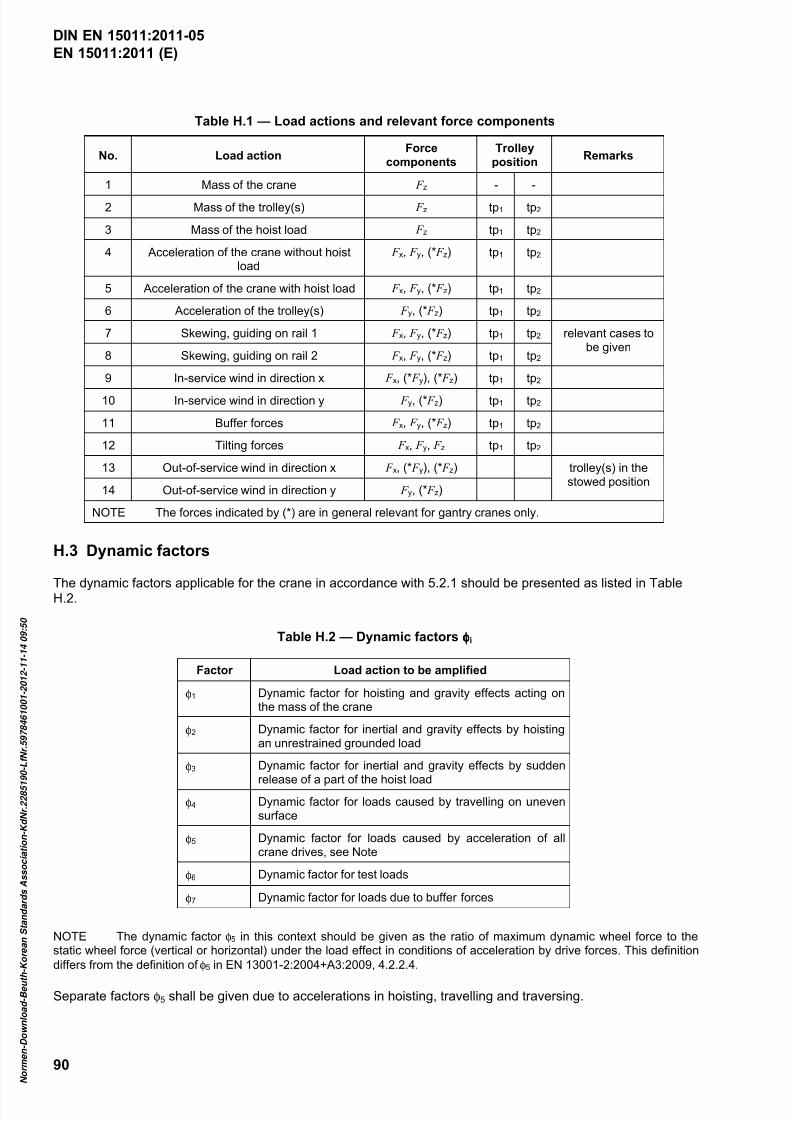
7/25/2019 DIN en 15011-2011 - Cranes - Bridge and Gantry Cranes
http://slidepdf.com/reader/full/din-en-15011-2011-cranes-bridge-and-gantry-cranes 92/95
EN 15011:2011 (E)
90
Table H.1 — Load actions and relevant force components
No. Load actionForce
components
Trolley
positionRemarks
1 Mass of the crane F z - -
2 Mass of the trolley(s) F z tp1 tp2
3 Mass of the hoist load F z tp1 tp2
4 Acceleration of the crane without hoistload
F x, F y, (* F z) tp1 tp2
5 Acceleration of the crane with hoist load F x, F y, (* F z) tp1 tp2
6 Acceleration of the trolley(s) F y, (* F z) tp1 tp2
7 Skewing, guiding on rail 1 F x, F y, (* F z) tp1 tp2 relevant cases tobe given
8 Skewing, guiding on rail 2 F x, F y, (* F z) tp1 tp2
9 In-service wind in direction x F x, (* F y), (* F z) tp1 tp2
10 In-service wind in direction y F y, (* F z) tp1 tp2
11 Buffer forces F x, F y, (* F z) tp1 tp2
12 Tilting forces F x, F y, F z tp1 tp2
13 Out-of-service wind in direction x F x, (* F y), (* F z) trolley(s) in thestowed position
14 Out-of-service wind in direction y F y, (* F z)
NOTE The forces indicated by (*) are in general relevant for gantry cranes only.
H.3 Dynamic factors
The dynamic factors applicable for the crane in accordance with 5.2.1 should be presented as listed in TableH.2.
Table H.2 — Dynamic factors φφφφi
Factor Load action to be amplified
φ1 Dynamic factor for hoisting and gravity effects acting onthe mass of the crane
φ2 Dynamic factor for inertial and gravity effects by hoistingan unrestrained grounded load
φ3 Dynamic factor for inertial and gravity effects by sudden
release of a part of the hoist loadφ4 Dynamic factor for loads caused by travelling on uneven
surface
φ5 Dynamic factor for loads caused by acceleration of allcrane drives, see Note
φ6 Dynamic factor for test loads
φ7 Dynamic factor for loads due to buffer forces
NOTE The dynamic factor φ5 in this context should be given as the ratio of maximum dynamic wheel force to thestatic wheel force (vertical or horizontal) under the load effect in conditions of acceleration by drive forces. This definition
differs from the definition of φ5 in EN 13001-2:2004+A3:2009, 4.2.2.4.
Separate factors φ5 shall be given due to accelerations in hoisting, travelling and traversing.
DIN EN 15011:2011-05

7/25/2019 DIN en 15011-2011 - Cranes - Bridge and Gantry Cranes
http://slidepdf.com/reader/full/din-en-15011-2011-cranes-bridge-and-gantry-cranes 93/95
EN 15011:2011 (E)
91
Annex I(informative)
Selection of a suitable set of crane standards for a given application
Is there a product standard in the following list that suits the application?
EN 13000 Cranes — Mobile cranes
EN 14439 Cranes — Safety — Tower cranes
EN 14985 Cranes — Slewing jib cranes
EN 15011 Cranes — Bridge and gantry cranes
EN 13852-1 Cranes — Offshore cranes — Part 1: General-purpose offshore cranes
EN 13852-2 Cranes — Offshore cranes — Part 2: Floating cranes
EN 14492-1 Cranes — Power driven winches and hoists — Part 1: Power driven winches
EN 14492-2 Cranes — Power driven winches and hoists — Part 2: Power driven hoists
EN 12999 Cranes — Loader cranes
EN 13155 Cranes — Safety — Non-fixed load lifting attachments
EN 13157 Cranes — Hand powered cranes
EN 14238 Cranes — Manually controlled load manipulating devices
YES NO
Use it directly, plus the
standards that are referred to
Use the following:
EN 13001-1 Cranes — General design — Part 1: General principles and requirements
EN 13001-2 Cranes safety — General design — Part 2: Load effects
prEN 13001-3-1 Cranes — General Design — Part 3.1: Limit States and proof competence of steelstructures
CEN/TS 13001-3-2 Cranes — General design — Part 3-2: Limit states and proof of competence of wire ropesin reeving systems
prCEN/TS 13001-3-3 Cranes — General design — Part 3-3: Limit states and proof of competence of wheel/rail
contacts
EN 13135-1 Cranes — Equipment — Part 1: Electrotechnical equipment
EN 13135-2 Cranes — Equipment — Part 2: Non-electrotechnical equipment
EN 13557 Cranes — Controls and control stations
EN 12077-2 Cranes safety — Requirements for health and safety — Part 2: Limiting and indicatingdevices
EN 13586 Cranes — Access
EN 14502-1 Cranes — Equipment for the lifting of persons — Part 1: Suspended baskets
EN 14502-2 Cranes — Equipment for the lifting of persons — Part 2: Elevating control stations
EN 12644-1 Cranes — Information for use and testing — Part 1: Instructions
EN 12644-2 Cranes — Information for use and testing — Part 2: Marking
DIN EN 15011:2011-05
7/25/2019 DIN en 15011-2011 - Cranes - Bridge and Gantry Cranes
http://slidepdf.com/reader/full/din-en-15011-2011-cranes-bridge-and-gantry-cranes 94/95
EN 15011:2011 (E)
92
Annex ZA(informative)
Relationship between this European standard and the Essential
Requirements of EU Directive 2006/42/EC
This European Standard has been prepared under a mandate given to CEN by the European Commission and the European Free Trade Association to provide a means of conforming to Essential Requirements of theNew Approach Directive 2006/42/EC on machinery.
Once this standard is cited in the Official Journal of the European Union under that Directive and has beenimplemented as a national standard in at least one Member State, compliance with the normative clauses ofthis standard confers, within the limits of the scope of this standard, a presumption of conformity with therelevant Essential Requirements of that Directive and associated EFTA regulations.
WARNING — Other requirements and other EU Directives may be applicable to the product(s) falling within the scope of this standard.
DIN EN 15011:2011-05

7/25/2019 DIN en 15011-2011 - Cranes - Bridge and Gantry Cranes
http://slidepdf.com/reader/full/din-en-15011-2011-cranes-bridge-and-gantry-cranes 95/95
EN 15011:2011 (E)
Bibliography
[1] EN 614-1, Safety of machinery — Ergonomic design principles — Part 1: Terminology and general principles
[2] EN 1050:1996, Safety of machinery — Principles for risk assessment
[3] EN 1991-3:2006, Eurocode 1 — Actions on structures — Part 3: Actions induced by cranes andmachinery
[4] prCEN/TS 13001-3-3 1), Cranes — General design — Part 3-3: Limit states and proof of competenceof wheel/rail contacts
[5] EN ISO 11688-2, Acoustics — Recommended practice for the design of low-noise machinery andequipment — Part 2: Introduction to the physics of low-noise design (ISO/TR 11688-2:1998)
[6] ISO 4301-1:1986, Cranes and lifting appliances — Classification — Part 1: General
[7] ISO 4309, Cranes — Wire ropes — Care and maintenance, inspection and discard
[8] ISO 8566-5, Cranes — Cabins — Part 5: Overhead travelling and portal bridge cranes
[9] ISO 9374-1, Cranes — Information to be provided — Part 1: General
[10] ISO 9374-5, Cranes — Information to be provided — Part 5: Overhead travelling cranes and portalbridge cranes
[11] ISO 9926-1, Cranes — Training of drivers — Part 1: General
[12] ISO 10245-5, Cranes — Limiting and indicating devices — Part 5: Overhead travelling and portal
bridge cranes
[13] ISO 11660-5, Cranes — Access, guards and restraints — Part 5: Bridge and gantry cranes
[14] ISO 12480-1, Cranes — Safe use — Part 1: General
[15] ISO 12482-1, Cranes — Condition monitoring — Part 1: General
[16] ISO 15513, Cranes — Competency requirements for crane drivers (operators), slingers, signallers andassessors
[17] ISO 16881-1, Cranes — Design calculation for rail wheels and associated trolley track supporting
t t P t 1 G l
DIN EN 15011:2011-05