Embed Size (px)
Citation preview
Digitally Controlled Solar Micro Inverter Designusing C2000 Piccolo Microcontroller
User's Guide
Literature Number: TIDU405BOctober 2014–Revised June 2017
2 TIDU405B–October 2014–Revised June 2017Submit Documentation Feedback
Copyright © 2014–2017, Texas Instruments Incorporated
Digitally Controlled Solar Micro Inverter using C2000™ PiccoloMicrocontroller
User's GuideTIDU405B–October 2014–Revised June 2017
Digitally Controlled Solar Micro Inverter using C2000™Piccolo Microcontroller
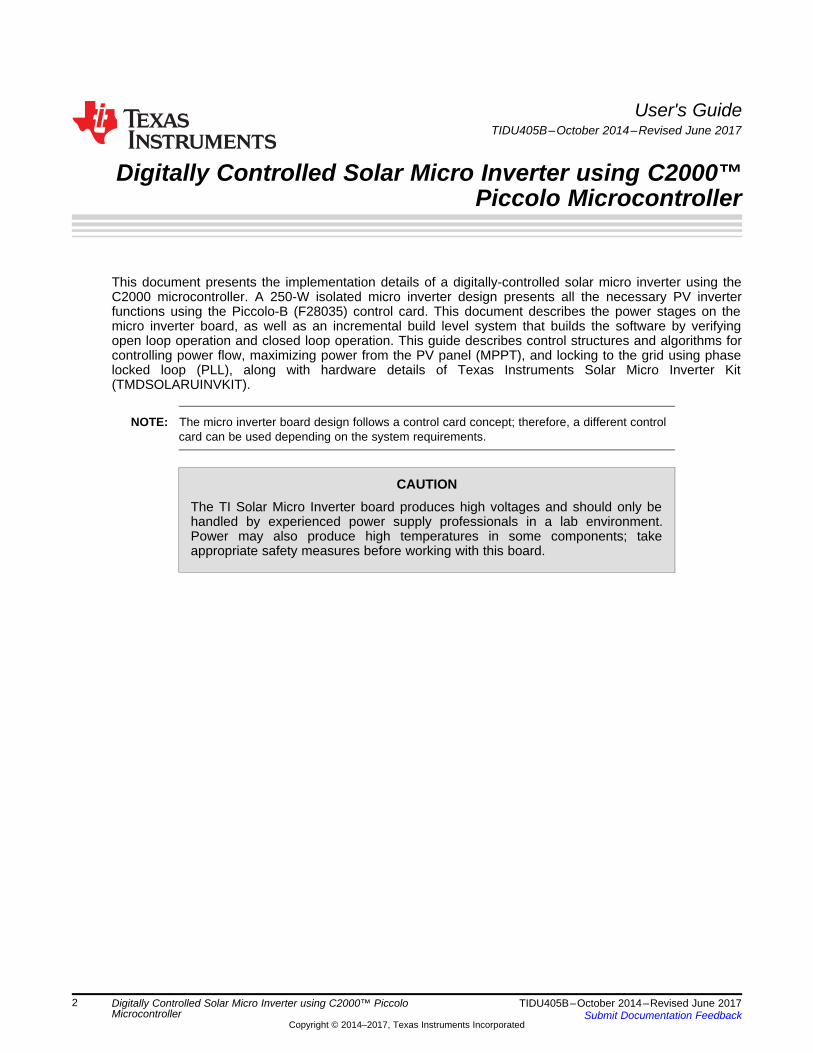
This document presents the implementation details of a digitally-controlled solar micro inverter using theC2000 microcontroller. A 250-W isolated micro inverter design presents all the necessary PV inverterfunctions using the Piccolo-B (F28035) control card. This document describes the power stages on themicro inverter board, as well as an incremental build level system that builds the software by verifyingopen loop operation and closed loop operation. This guide describes control structures and algorithms forcontrolling power flow, maximizing power from the PV panel (MPPT), and locking to the grid using phaselocked loop (PLL), along with hardware details of Texas Instruments Solar Micro Inverter Kit(TMDSOLARUINVKIT).
NOTE: The micro inverter board design follows a control card concept; therefore, a different controlcard can be used depending on the system requirements.
CAUTIONThe TI Solar Micro Inverter board produces high voltages and should only behandled by experienced power supply professionals in a lab environment.Power may also produce high temperatures in some components; takeappropriate safety measures before working with this board.
Active Clamp Fly-back DC-DC DC-AC InverterPV Panel
Output AC Out
Isolated MPPT Solar Micro Inverter
HV DC Bus
PiccoloDigital Controller
IsolationBoundary
Photovoltaic Panel
GridDC-DC BoostWith MPPT
Single Phase Inverter
Solar Micro Inverter
www.ti.com Introduction
3TIDU405B–October 2014–Revised June 2017Submit Documentation Feedback
Copyright © 2014–2017, Texas Instruments Incorporated
Digitally Controlled Solar Micro Inverter using C2000™ PiccoloMicrocontroller
1 IntroductionEnergy from renewable sources, such as solar and wind, is gaining interest as the world’s power demandincreases and non-renewable resources are depleted. A large component of this demand is fromindustries and houses connected to the electrical grid. Because of this, attempts are made to raise thepercentage of energy sourced from renewable sources into the grid. Photovoltaic (PV) energy sourcesincrease the renewable content because of their ubiquitous nature and extended life time due to anabsence of moving parts.
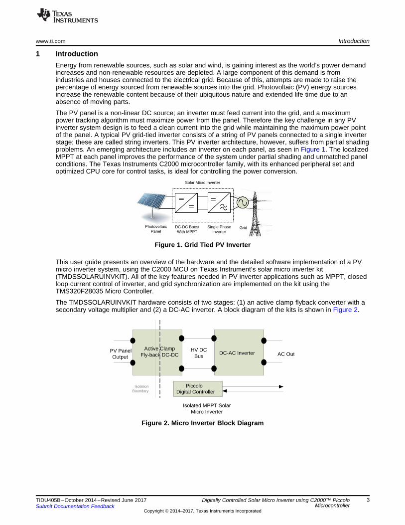
The PV panel is a non-linear DC source; an inverter must feed current into the grid, and a maximumpower tracking algorithm must maximize power from the panel. Therefore the key challenge in any PVinverter system design is to feed a clean current into the grid while maintaining the maximum power pointof the panel. A typical PV grid-tied inverter consists of a string of PV panels connected to a single inverterstage; these are called string inverters. This PV inverter architecture, however, suffers from partial shadingproblems. An emerging architecture includes an inverter on each panel, as seen in Figure 1. The localizedMPPT at each panel improves the performance of the system under partial shading and unmatched panelconditions. The Texas Instruments C2000 microcontroller family, with its enhanced peripheral set andoptimized CPU core for control tasks, is ideal for controlling the power conversion.
Figure 1. Grid Tied PV Inverter
This user guide presents an overview of the hardware and the detailed software implementation of a PVmicro inverter system, using the C2000 MCU on Texas Instrument’s solar micro inverter kit(TMDSSOLARUINVKIT). All of the key features needed in PV inverter applications such as MPPT, closedloop current control of inverter, and grid synchronization are implemented on the kit using theTMS320F28035 Micro Controller.
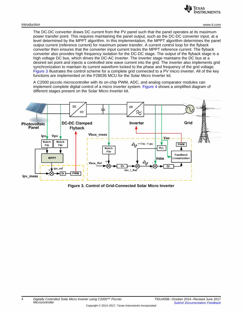
The TMDSSOLARUINVKIT hardware consists of two stages: (1) an active clamp flyback converter with asecondary voltage multiplier and (2) a DC-AC inverter. A block diagram of the kits is shown in Figure 2.
Figure 2. Micro Inverter Block Diagram
Introduction www.ti.com
4 TIDU405B–October 2014–Revised June 2017Submit Documentation Feedback
Copyright © 2014–2017, Texas Instruments Incorporated
Digitally Controlled Solar Micro Inverter using C2000™ PiccoloMicrocontroller
The DC-DC converter draws DC current from the PV panel such that the panel operates at its maximumpower transfer point. This requires maintaining the panel output, such as the DC-DC converter input, at alevel determined by the MPPT algorithm. In this implementation, the MPPT algorithm determines the paneloutput current (reference current) for maximum power transfer. A current control loop for the flybackconverter then ensures that the converter input current tracks the MPPT reference current. The flybackconverter also provides high frequency isolation for the DC-DC stage. The output of the flyback stage is ahigh voltage DC bus, which drives the DC-AC inverter. The inverter stage maintains the DC bus at adesired set point and injects a controlled sine wave current into the grid. The inverter also implements gridsynchronization to maintain its current waveform locked to the phase and frequency of the grid voltage.Figure 3 illustrates the control scheme for a complete grid connected to a PV micro inverter. All of the keyfunctions are implemented on the F28035 MCU for the Solar Micro Inverter kit.
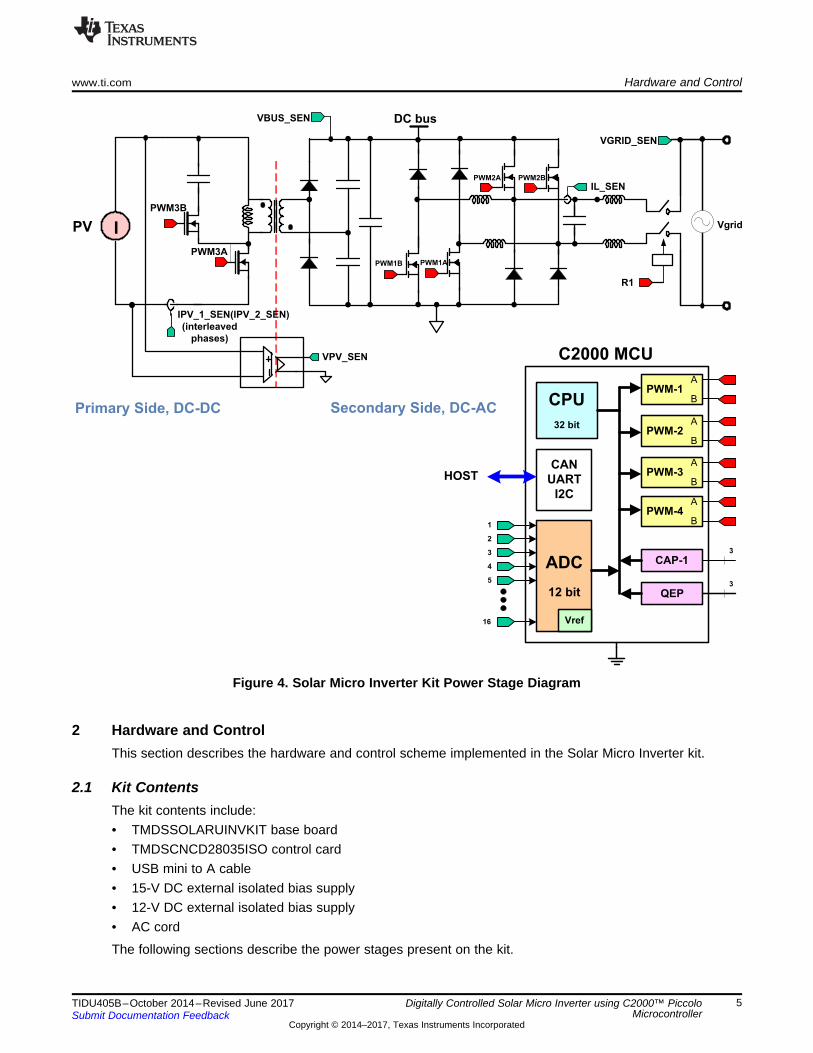
A C2000 piccolo microcontroller with its on-chip PWM, ADC, and analog comparator modules canimplement complete digital control of a micro inverter system. Figure 4 shows a simplified diagram ofdifferent stages present on the Solar Micro Inverter kit.
Figure 3. Control of Grid-Connected Solar Micro Inverter
PWM-1
C2000 MCU
CAN
UART
I2C
CPU
32 bit
A
B
PWM-2A
B
PWM-3A
B
PWM-4A
B
CAP-1ADC
12 bit
Vref
1
2
3
4
5
16
QEP3
HOST
3
PV
DC bus
PWM1B
VBUS_SEN
VGRID_SEN
PWM3A
PWM3B
I
IPV_1_SEN(IPV_2_SEN)
(interleaved
phases)
IL_SEN
VPV_SEN
PWM1A
PWM2A PWM2B
Vgrid
R1
Primary Side, DC-DC Secondary Side, DC-AC
www.ti.com Hardware and Control
5TIDU405B–October 2014–Revised June 2017Submit Documentation Feedback
Copyright © 2014–2017, Texas Instruments Incorporated
Digitally Controlled Solar Micro Inverter using C2000™ PiccoloMicrocontroller
Figure 4. Solar Micro Inverter Kit Power Stage Diagram
2 Hardware and ControlThis section describes the hardware and control scheme implemented in the Solar Micro Inverter kit.
2.1 Kit ContentsThe kit contents include:• TMDSSOLARUINVKIT base board• TMDSCNCD28035ISO control card• USB mini to A cable• 15-V DC external isolated bias supply• 12-V DC external isolated bias supply• AC cord
The following sections describe the power stages present on the kit.
C2000 MCUPiccolo Controller
Sig
nal I
/F
Con
ditio
ning
Driv
ers
IpvVpv
Vbus
PWM3APWM3B
PWM1APWM1B
PWM2APWM2B
ILVLN
ipv
PV PanelOutput
Vpv
ipv Vbus
Qac
Cin
Lp
Lm
T1
PWM3A
PWM3B
Ls
HV DC Bus
Cout
D2 C2
D1 C1
ip
im is
Cac
Q1
Np Ns RL
Hardware and Control www.ti.com
6 TIDU405B–October 2014–Revised June 2017Submit Documentation Feedback
Copyright © 2014–2017, Texas Instruments Incorporated
Digitally Controlled Solar Micro Inverter using C2000™ PiccoloMicrocontroller
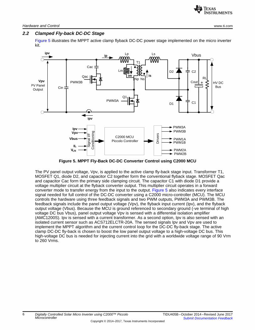
2.2 Clamped Fly-back DC-DC StageFigure 5 illustrates the MPPT active clamp flyback DC-DC power stage implemented on the micro inverterkit.
Figure 5. MPPT Fly-Back DC-DC Converter Control using C2000 MCU
The PV panel output voltage, Vpv, is applied to the active clamp fly-back stage input. Transformer T1,MOSFET Q1, diode D2, and capacitor C2 together form the conventional flyback stage. MOSFET Qacand capacitor Cac form the primary side clamping circuit. The capacitor C1 with diode D1 provide avoltage multiplier circuit at the flyback converter output. This multiplier circuit operates in a forwardconverter mode to transfer energy from the input to the output. Figure 5 also indicates every interfacesignal needed for full control of the DC-DC converter using a C2000 micro-controller (MCU). The MCUcontrols the hardware using three feedback signals and two PWM outputs, PWM3A and PWM3B. Thefeedback signals include the panel output voltage (Vpv), the flyback input current (Ipv), and the flybackoutput voltage (Vbus). Because the MCU is ground referenced to secondary ground (-ve terminal of highvoltage DC bus Vbus), panel output voltage Vpv is sensed with a differential isolation amplifier(AMC1200S). Ipv is sensed with a current transformer. As a second option, Ipv is also sensed with anisolated current sensor such as ACS712ELCTR-20A. The sensed signals Ipv and Vpv are used toimplement the MPPT algorithm and the current control loop for the DC-DC fly-back stage. The activeclamp DC-DC fly-back is chosen to boost the low panel output voltage to a high-voltage DC bus. Thishigh-voltage DC bus is needed for injecting current into the grid with a worldwide voltage range of 90 Vrmto 260 Vrms.
VLNDC BusVoltage
Vbus
Q9
Q4
PWM1A
L3
L4
C5
D3
D9
D4
D8
C4 Vg
PWM1B
Q8
Q3
Q4
Q8
Q9
VLN
Vgs
PWM
Q3
PWM2APWM2B
IL
L
N
L1
L2
RL1
www.ti.com Hardware and Control
7TIDU405B–October 2014–Revised June 2017Submit Documentation Feedback
Copyright © 2014–2017, Texas Instruments Incorporated
Digitally Controlled Solar Micro Inverter using C2000™ PiccoloMicrocontroller
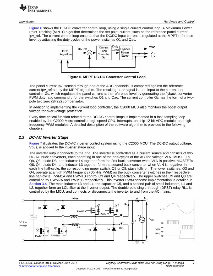
Figure 6 shows the DC-DC converter control loop, using a single current control loop. A Maximum PowerPoint Tracking (MPPT) algorithm determines the set point current, such as the reference panel currentIpv_ref. The current control loop ensures that the DC/DC input current is regulated at the MPPT referencelevel by adjusting the duty cycles of the power switches Q1 and Qac.
Figure 6. MPPT DC-DC Converter Control Loop
The panel current Ipv, sensed through one of the ADC channels, is compared against the referencecurrent Ipv_ref set by the MPPT algorithm. The resulting error signal is then input to the current loopcontroller Gc, which regulates the panel current at the reference level by generating the flyback converterPWM duty ratio command d for the switches Q1 and Qac. The current controller Gc has the form of a two-pole two zero (2P2Z) compensator.
In addition to implementing the current loop controller, the C2000 MCU also monitors the boost outputvoltage for over-voltage protection.
Every time critical function related to the DC-DC control loops is implemented in a fast sampling loopenabled by the C2000 Micro-controller high speed CPU, interrupts, on chip 12-bit ADC module, and highfrequency PWM modules. A detailed description of the software algorithm is provided in the followingchapters.
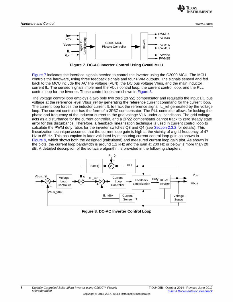
2.3 DC-AC Inverter StageFigure 7 illustrates the DC-AC inverter control system using the C2000 MCU. The DC-DC output voltage,Vbus, is applied to the inverter stage input.
The inverter output connects to the grid. The inverter is controlled as a current source and consists of twoDC-AC buck converters, each operating in one of the half-cycles of the AC line voltage VLN. MOSFETsQ9, Q3, diode D3, and inductor L4 together form the first buck converter when VLN is positive. MOSFETsQ8, Q4, diode D4, and inductor L3 together form the second buck converter when VLN is negative. Ineach line half-cycle, the corresponding upper switch, Q9 or Q8, stays fully on. The lower switches, Q3 andQ4, operate at a high PWM frequency (50-kHz PWM) as the buck converter switches in their respectiveline half-cycle. PWM1A and PWM1B control Q3 and Q4 respectively. The upper switches Q9 and Q8 arecontrolled by PWM2A and PWM2B respectively. This inverter PWM scheme implementation is detailed inSection 3.4. The main inductor L3 and L4, the capacitor C5, and a second pair of small inductors, L1 andL2, together form an LCL filter at the inverter output. The double pole single through (DPST) relay RL1 iscontrolled by the MCU, and connects or disconnects the inverter to and from the AC mains.
DC-AC Inverter
IL_fdbk
Vbus
Current Loop
Controller
PLL
Voltage Loop
Controller
Vbus_refIL _ref Duty
Ph_0
Sine ()
Current Sense
Voltage Sense
Vbus_fdbk
VLN
FeedbackLinearization
C2000 MCUPiccolo Controller
Sig
nal I
/F
Con
ditio
ning
Driv
ers
IpvVpv
Vbus
PWM3APWM3B
PWM1APWM1B
PWM2APWM2B
ILVLN
Hardware and Control www.ti.com
8 TIDU405B–October 2014–Revised June 2017Submit Documentation Feedback
Copyright © 2014–2017, Texas Instruments Incorporated
Digitally Controlled Solar Micro Inverter using C2000™ PiccoloMicrocontroller
Figure 7. DC-AC Inverter Control Using C2000 MCU
Figure 7 indicates the interface signals needed to control the inverter using the C2000 MCU. The MCUcontrols the hardware, using three feedback signals and four PWM outputs. The signals sensed and fedback to the MCU include the AC line voltage (VLN), the DC bus voltage Vbus, and the main inductorcurrent IL. The sensed signals implement the Vbus control loop, the current control loop, and the PLLcontrol loop for the Inverter. These control loops are shown in Figure 8.
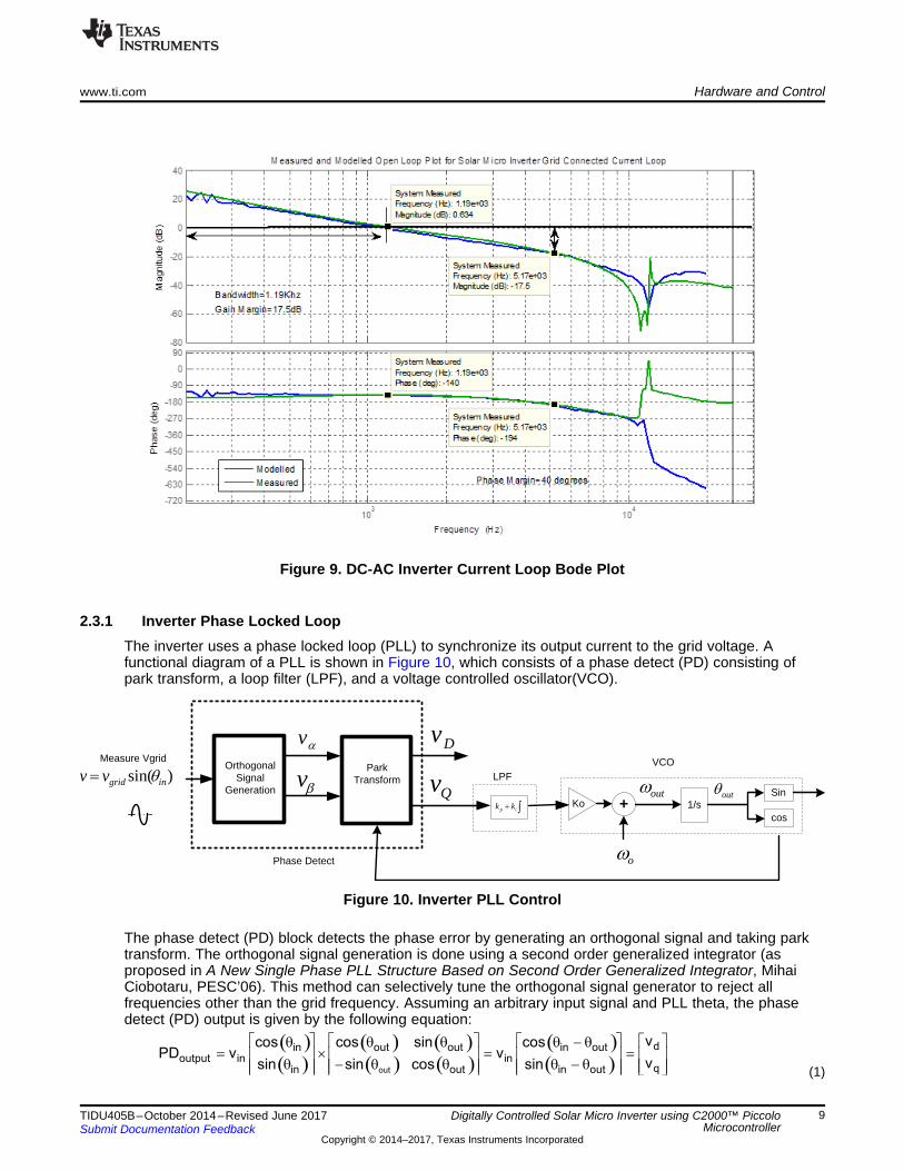
The voltage control loop employs a two pole two zero (2P2Z) compensator and regulates the input DC busvoltage at the reference level Vbus_ref by generating the reference current command for the current loop.The current loop forces the inductor current IL to track the reference signal IL_ref generated by the voltageloop. The current controller has the form of a 3P3Z compensator. The PLL controller allows for locking thephase and frequency of the inductor current to the grid voltage VLN under all conditions. The grid voltageacts as a disturbance for the current controller, and a 2P2Z compensator cannot track to zero steady stateerror for this disturbance. Therefore, a feedback linearization technique is used in current control loop tocalculate the PWM duty ratios for the inverter switches Q3 and Q4 (see Section 2.3.2 for details). Thislinearization technique assumes that the current loop gain is high at the vicinity of a grid frequency of 47Hz to 65 Hz. This assumption is later validated by measuring current control loop gain as shown inFigure 9, which shows both the designed (calculated) and measured current loop gain plot. As shown inthe plots, the current loop bandwidth is around 1.2 kHz and the gain at 200 Hz or below is more than 20dB. A detailed description of the software algorithm is provided in the following chapters.
Figure 8. DC-AC Inverter Control Loop
( )( )
( ) ( )( ) ( )
( )( )out
din out out in outoutput in in
qin out in out
vcos cos sin cosPD v v
vsin sin cos sin
é ù é ù é ù é ùq q q q - q= ´ = =ê ú ê ú ê ú ê ú
q - q q q - q ê úê ú ê ú ê ú ë ûë û ë û ë û
Measure Vgrid
oZ
)sin( ingridvv T
³� ip kk
Dv
LPF
Ko +outZ
1/soutT
cos
Sin
VCOOrthogonal Signal
Generation EvPark
Transform
Dv
Qv
Phase Detect
www.ti.com Hardware and Control
9TIDU405B–October 2014–Revised June 2017Submit Documentation Feedback
Copyright © 2014–2017, Texas Instruments Incorporated
Digitally Controlled Solar Micro Inverter using C2000™ PiccoloMicrocontroller
Figure 9. DC-AC Inverter Current Loop Bode Plot
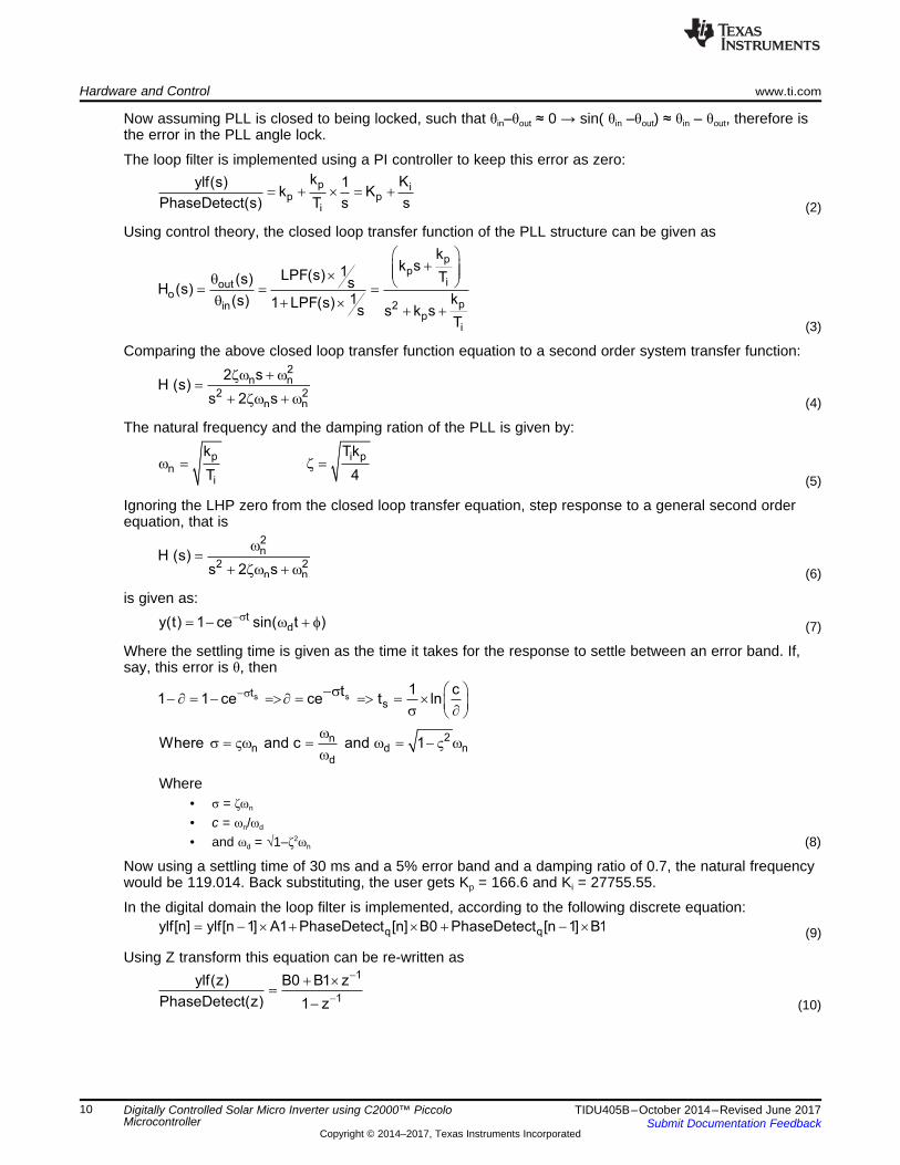
2.3.1 Inverter Phase Locked LoopThe inverter uses a phase locked loop (PLL) to synchronize its output current to the grid voltage. Afunctional diagram of a PLL is shown in Figure 10, which consists of a phase detect (PD) consisting ofpark transform, a loop filter (LPF), and a voltage controlled oscillator(VCO).
Figure 10. Inverter PLL Control
The phase detect (PD) block detects the phase error by generating an orthogonal signal and taking parktransform. The orthogonal signal generation is done using a second order generalized integrator (asproposed in A New Single Phase PLL Structure Based on Second Order Generalized Integrator, MihaiCiobotaru, PESC’06). This method can selectively tune the orthogonal signal generator to reject allfrequencies other than the grid frequency. Assuming an arbitrary input signal and PLL theta, the phasedetect (PD) output is given by the following equation:
(1)
1
1
ylf(z) B0 B1 z
PhaseDetect(z) 1 z
-
-
+ ´=
-
q qylf[n] ylf[n 1] A1 PhaseDetect [n] B0 PhaseDetect [n 1] B1= - ´ + ´ + - ´
s st
s
2nn d n
d
1 ct1 1 ce ce t ln
Where and c and 1
-s æ ö-s- ¶ = - =>¶ = => = ´ ç ÷s ¶è øw
s = Vw = w = - V ww
tdy(t) 1 ce sin( t )-s= - w + f
2n
2 2n n
H (s)s 2 s
w=
+ zw + w
p i pn
i
k Tk
T 4w = z =
2n n
2 2n n
2 sH (s)
s 2 s
zw + w=
+ zw + w
pp
iouto
p2inp
i
kk s1LPF(s) T(s) sH (s)
1 k(s) 1 LPF(s)s s k s
T
æ ö+ç ÷ç ÷´q è ø= = =
q + ´+ +
p ip p
i
k Kylf(s) 1k K
PhaseDetect(s) T s s= + ´ = +
Hardware and Control www.ti.com
10 TIDU405B–October 2014–Revised June 2017Submit Documentation Feedback
Copyright © 2014–2017, Texas Instruments Incorporated
Digitally Controlled Solar Micro Inverter using C2000™ PiccoloMicrocontroller
Now assuming PLL is closed to being locked, such that θin–θout ≈ 0 → sin( θin –θout) ≈ θin – θout, therefore isthe error in the PLL angle lock.
The loop filter is implemented using a PI controller to keep this error as zero:
(2)
Using control theory, the closed loop transfer function of the PLL structure can be given as
(3)
Comparing the above closed loop transfer function equation to a second order system transfer function:
(4)
The natural frequency and the damping ration of the PLL is given by:
(5)
Ignoring the LHP zero from the closed loop transfer equation, step response to a general second orderequation, that is
(6)
is given as:
(7)
Where the settling time is given as the time it takes for the response to settle between an error band. If,say, this error is θ, then
Where• σ = ζωn
• c = ωn/ωd
• and ωd = √1–ζ2ωn (8)
Now using a settling time of 30 ms and a 5% error band and a damping ratio of 0.7, the natural frequencywould be 119.014. Back substituting, the user gets Kp = 166.6 and Ki = 27755.55.
In the digital domain the loop filter is implemented, according to the following discrete equation:
(9)
Using Z transform this equation can be re-written as
(10)
LineV
busV-d
+Zgrid(s)
Ui LIGp(s)
Li Ri Lg Rg
Cf
Rf
Vc
ivgv
ci
giLi
Zi Zg
Zc
( )( )
bus c gL
g c c g i
V Z Zi
d Z Z Z Z Z
+=
´ + + ´
%
%
p i p i2 K K T 2 K K TB0 and B1
2 2
´ + ´ ´ - ´æ ö æ ö= =ç ÷ ç ÷ç ÷ ç ÷
è ø è ø
p i p i 1
1
2 K K T 2 K K Tz
2 2ylf(z)
PhaseDetect(z) 1 z
-
-
´ + ´ ´ - ´æ ö æ ö-ç ÷ ç ÷ç ÷ ç ÷
è ø è ø=-
2 z 1s
T z 1
-æ ö= ç ÷+è ø
www.ti.com Hardware and Control
11TIDU405B–October 2014–Revised June 2017Submit Documentation Feedback
Copyright © 2014–2017, Texas Instruments Incorporated
Digitally Controlled Solar Micro Inverter using C2000™ PiccoloMicrocontroller
Now using Bi-linear transformation on the LPF transfer function, replace where T= SamplingTime:
(11)
Equation 10 and Equation 11 can be compared to map the proportional and integral gain of the PIcontroller from the analog domain into the digital domain.
(12)
For example, on the micro inverter kit the ISR rate is 50 Khz, and therefore B0 = 166.877556 and B1 =-166.322444 are used for the loop filter.
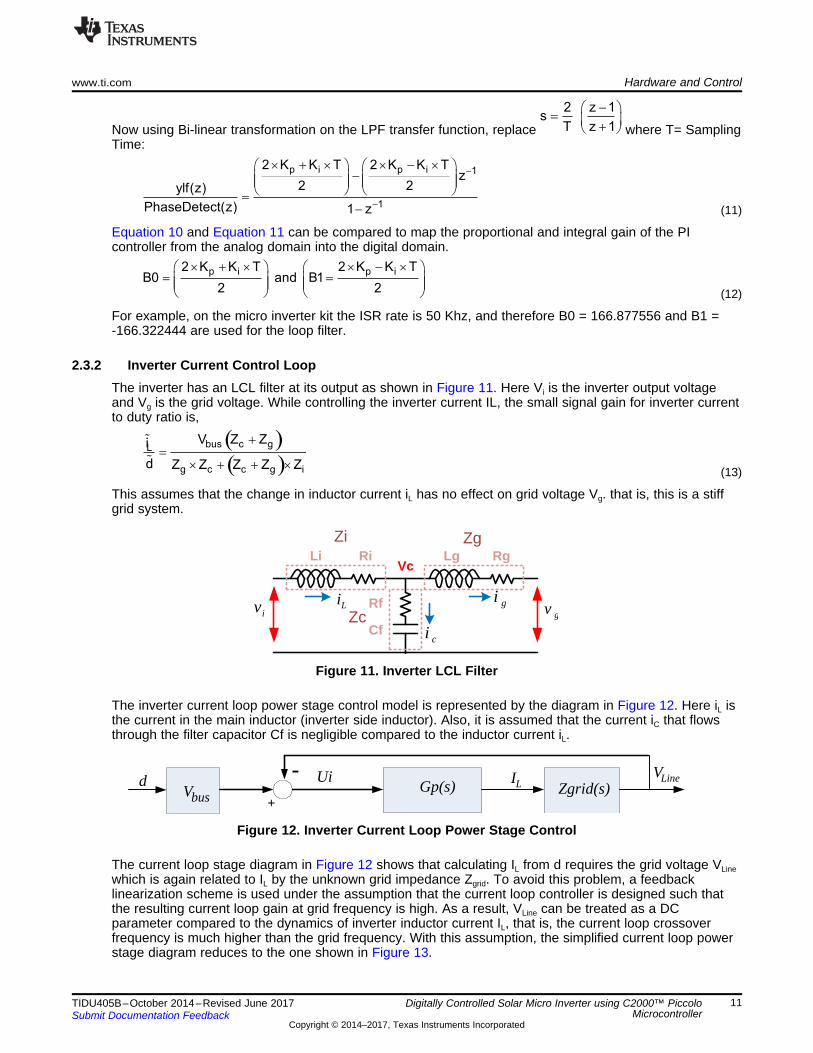
2.3.2 Inverter Current Control LoopThe inverter has an LCL filter at its output as shown in Figure 11. Here Vi is the inverter output voltageand Vg is the grid voltage. While controlling the inverter current IL, the small signal gain for inverter currentto duty ratio is,
(13)
This assumes that the change in inductor current iL has no effect on grid voltage Vg. that is, this is a stiffgrid system.
Figure 11. Inverter LCL Filter
The inverter current loop power stage control model is represented by the diagram in Figure 12. Here iL isthe current in the main inductor (inverter side inductor). Also, it is assumed that the current iC that flowsthrough the filter capacitor Cf is negligible compared to the inductor current iL.
Figure 12. Inverter Current Loop Power Stage Control
The current loop stage diagram in Figure 12 shows that calculating IL from d requires the grid voltage VLinewhich is again related to IL by the unknown grid impedance Zgrid. To avoid this problem, a feedbacklinearization scheme is used under the assumption that the current loop controller is designed such thatthe resulting current loop gain at grid frequency is high. As a result, VLine can be treated as a DCparameter compared to the dynamics of inverter inductor current IL, that is, the current loop crossoverfrequency is much higher than the grid frequency. With this assumption, the simplified current loop powerstage diagram reduces to the one shown in Figure 13.

1 2 3
c 1 2 3
0.2866 0.3173z 0.338z 0.2616zG (z)
1 1.584z 0.6978z 0.1137z
- - -
- - -
- + -=
- + -
loop c s pG (s) G (s) K G=
lIbusV
+)(sGc
- bus
1
V
+d -
sK
Iref UiUi
LineV
Zgrid(s) LineV)(sGP
LineV
+
1+
d -Uibus
Vbus
V
UiZgrid(s)
LineVLI
Gp(s)
Hardware and Control www.ti.com
12 TIDU405B–October 2014–Revised June 2017Submit Documentation Feedback
Copyright © 2014–2017, Texas Instruments Incorporated
Digitally Controlled Solar Micro Inverter using C2000™ PiccoloMicrocontroller
Figure 13. Simplified Current Loop Power Stage Control
The simplified diagram in Figure 13 shows that the current loop power stage input is Ui, which controls theinductor current IL. This is valid when the input Ui is controlled by a current loop controller, such that theloop gain at grid frequency is high. The diagram also shows how the PWM duty ratio d is calculated fromUi using the measured values of Vbus and VLine. This can be done in firmware. Adding the current controllerGc, to the power stage diagram in Figure 13, the complete current control loop diagram becomes as theone shown in Figure 14.
Figure 14. Inverter Current Control Loop
Where, Ks is the current feedback gain. Therefore, the loop gain transfer function of the control loop is:
(14)
Using Matlab the current controller is designed as the following 3P3Z controller:
(15)
The loop gain Bode plot for the current loop is shown previously in Figure 9. The plot shows that the cutofffrequency of the current loop is around 1.19 kHz, and the system is stable with good phase margin (PM)and gain margin (GM).
2.4 Solar Micro Inverter Electrical SpecificationsThe following lists the key highlights of the micro inverter:• Panel voltage: 28 V (min) to 45 V (max)• DC bus voltage: 400 V (max)• Output power: 280 W @ 220Vac, 140 W @ 110Vac• DC-DC and DC-AC combined efficiency around 92% at 50% rated load, THD around 5%
NOTE: For 220-V/50-Hz grid operation, the EVM was only tested with an emulated grid, that is, anexternal AC source (at least 600-VA rating) with a load resistor (200.0-Ohm, 600-W rating) atthe output. Therefore, EVM supplied power to the load and not back to the AC supply.
3 Software ImplementationThis section describes the details of software implementation of control of PV micro inverter.
Peripheral ConfigurationInverter- PWM1,2Flyback ± PWM3
ADC
Cinit_0
Initialize Solar Lib Blocks± MPPT, SizeAnalyzer, CNTL ...
Initialize Control Variables for flyback and inverter
Enable InterruptsInverter ± ADCINT1Boost ± EPWM_INT
BackGround LoopInv_ISR
OneKhzISR
Save contexts and clear interrupt flags - EINT
C ± ISR(Inverter Control)
State MachineExecute state machine checks
Power MeasurementExecute Power Measurement and grid frequency check calculation
Run MPPT
Restore ContextReturn
(ii)OneKhzISR(1Khz) Save contexts and clear int flags
ASM ± ISR(Boost Control)
Inverter ControlADC Result read Inv curr & voltage
Run PLLCheck for ZCD
Execute CNTL_PI_IQ ± Voltage LoopExecute CNTL_3P3Z_IQ ± Current Loop
Update PWM Drivers for inverter
Flyback ControlADC Result read Ipv curr & voltage
Execute CNTL_2P2Z_IQ ± Current LoopUpdate PWM Drivers for flyback
Restore ContextReturn
(iii)inv_ISR(50 Khz)
(i) Main Loop
FiltersRun Notch filters and averaging filters on
panel current, voltage and DC bus measurements
www.ti.com Software Implementation
13TIDU405B–October 2014–Revised June 2017Submit Documentation Feedback
Copyright © 2014–2017, Texas Instruments Incorporated
Digitally Controlled Solar Micro Inverter using C2000™ PiccoloMicrocontroller
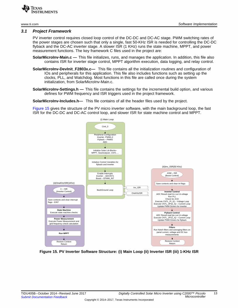
3.1 Project FrameworkPV inverter control requires closed loop control of the DC-DC and DC-AC stage. PWM switching rates ofthe power stages are chosen such that only a single, fast 50-KHz ISR is needed for controlling the DC-DCflyback and the DC-AC inverter stage. A slower ISR (1 KHz) runs the state machine, MPPT, and powermeasurement functions. The key framework C files used in the project are:
SolarMicroInv-Main.c — This file initializes, runs, and manages the application. In addition, this file alsocontains ISR for inverter stage control, MPPT algorithm execution, data logging, and relay control.
SolarMicroInv-DevInit_F2803x.c— This file contains all the initialization routines and configuration ofIOs and peripherals for this application. This file also includes functions such as setting up theclocks, PLL, and Watchdog. Most functions in this file are called once during the systeminitialization, from SolarMicroInv-Main.c.
SolarMicroInv-Settings.h — This file contains the settings for the incremental build option, and variousdefines for PWM frequency and ISR triggers used in the project framework.
SolarMicroInv-Includes.h— This file contains of all the header files used by the project.
Figure 15 gives the structure of the PV micro inverter software, with the main background loop, the fastISR for the DC-DC and DC-AC control loop, and slower ISR for state machine control and MPPT.
Figure 15. PV Inverter Software Structure: (i) Main Loop (ii) Inverter ISR (iii) 1-KHz ISR
Software Implementation www.ti.com
14 TIDU405B–October 2014–Revised June 2017Submit Documentation Feedback
Copyright © 2014–2017, Texas Instruments Incorporated
Digitally Controlled Solar Micro Inverter using C2000™ PiccoloMicrocontroller
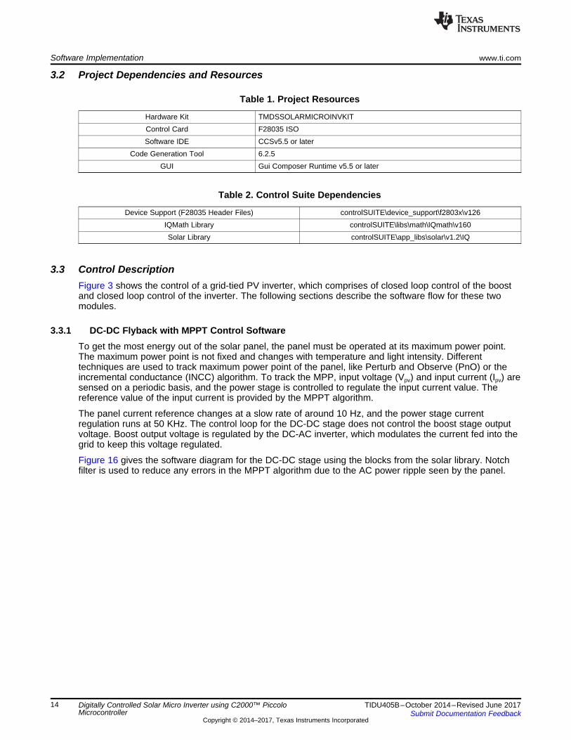
3.2 Project Dependencies and Resources
Table 1. Project Resources
Hardware Kit TMDSSOLARMICROINVKITControl Card F28035 ISOSoftware IDE CCSv5.5 or later
Code Generation Tool 6.2.5GUI Gui Composer Runtime v5.5 or later
Table 2. Control Suite Dependencies
Device Support (F28035 Header Files) controlSUITE\device_support\f2803x\v126IQMath Library controlSUITE\libs\math\IQmath\v160Solar Library controlSUITE\app_libs\solar\v1.2\IQ
3.3 Control DescriptionFigure 3 shows the control of a grid-tied PV inverter, which comprises of closed loop control of the boostand closed loop control of the inverter. The following sections describe the software flow for these twomodules.
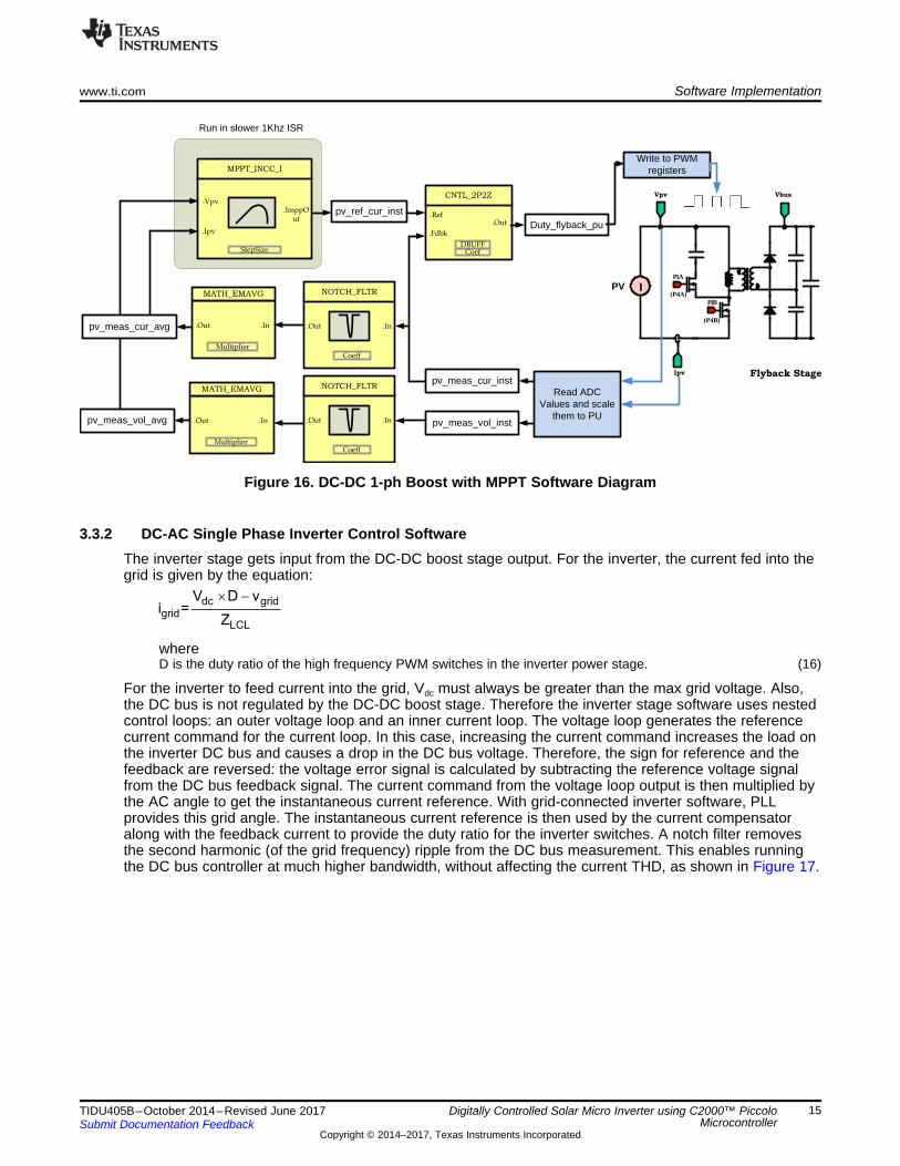
3.3.1 DC-DC Flyback with MPPT Control SoftwareTo get the most energy out of the solar panel, the panel must be operated at its maximum power point.The maximum power point is not fixed and changes with temperature and light intensity. Differenttechniques are used to track maximum power point of the panel, like Perturb and Observe (PnO) or theincremental conductance (INCC) algorithm. To track the MPP, input voltage (Vpv) and input current (Ipv) aresensed on a periodic basis, and the power stage is controlled to regulate the input current value. Thereference value of the input current is provided by the MPPT algorithm.
The panel current reference changes at a slow rate of around 10 Hz, and the power stage currentregulation runs at 50 KHz. The control loop for the DC-DC stage does not control the boost stage outputvoltage. Boost output voltage is regulated by the DC-AC inverter, which modulates the current fed into thegrid to keep this voltage regulated.
Figure 16 gives the software diagram for the DC-DC stage using the blocks from the solar library. Notchfilter is used to reduce any errors in the MPPT algorithm due to the AC power ripple seen by the panel.
dc gridgrid
LCL
V D vi =
Z
´ -
Vpv
Flyback StageIpv
PV
P1B
P1A
I(P4A)
(P4B)
Vbus
.In
NOTCH_FLTR
.Out
Coeff
.In
NOTCH_FLTR
.Out
Coeff
Read ADC Values and scale
them to PU
pv_meas_cur_inst
.Vpv
MPPT_INCC_I
StepSize
.ImppOut
.Ipv.Out
.Ref
.Fdbk
CNTL_2P2Z
DBUFFCoef
pv_meas_vol_inst
MATH_EMAVG
.In.Out
Multiplier
MATH_EMAVG
.In.Out
Multiplier
pv_ref_cur_instDuty_flyback_pu
Write to PWM registers
pv_meas_cur_avg
pv_meas_vol_avg
Run in slower 1Khz ISR
www.ti.com Software Implementation
15TIDU405B–October 2014–Revised June 2017Submit Documentation Feedback
Copyright © 2014–2017, Texas Instruments Incorporated
Digitally Controlled Solar Micro Inverter using C2000™ PiccoloMicrocontroller
Figure 16. DC-DC 1-ph Boost with MPPT Software Diagram
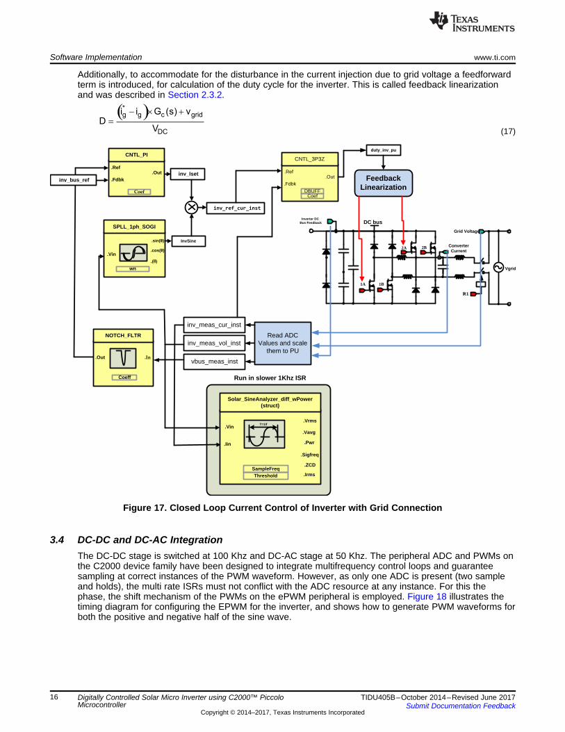
3.3.2 DC-AC Single Phase Inverter Control SoftwareThe inverter stage gets input from the DC-DC boost stage output. For the inverter, the current fed into thegrid is given by the equation:
whereD is the duty ratio of the high frequency PWM switches in the inverter power stage. (16)
For the inverter to feed current into the grid, Vdc must always be greater than the max grid voltage. Also,the DC bus is not regulated by the DC-DC boost stage. Therefore the inverter stage software uses nestedcontrol loops: an outer voltage loop and an inner current loop. The voltage loop generates the referencecurrent command for the current loop. In this case, increasing the current command increases the load onthe inverter DC bus and causes a drop in the DC bus voltage. Therefore, the sign for reference and thefeedback are reversed: the voltage error signal is calculated by subtracting the reference voltage signalfrom the DC bus feedback signal. The current command from the voltage loop output is then multiplied bythe AC angle to get the instantaneous current reference. With grid-connected inverter software, PLLprovides this grid angle. The instantaneous current reference is then used by the current compensatoralong with the feedback current to provide the duty ratio for the inverter switches. A notch filter removesthe second harmonic (of the grid frequency) ripple from the DC bus measurement. This enables runningthe DC bus controller at much higher bandwidth, without affecting the current THD, as shown in Figure 17.
Feedback Linearization
Inverter DC Bus Feedback DC bus
1A
Grid Voltage
Converter Current
1B
2A 2B
Vgrid
R1
.Out.Ref
.Fdbk
CNTL_PI
Coef
inv_bus_ref inv_Iset
Read ADC Values and scale
them to PU
inv_meas_cur_inst
inv_meas_vol_inst
vbus_meas_inst.In
NOTCH_FLTR
.Out
Coeff
.cos(�).Vin
SPLL_1ph_SOGI
wn
.(É)
.sin(�) InvSine
duty_inv_pu
.Out.Ref
.Fdbk
CNTL_3P3Z
DBUFFCoef
inv_ref_cur_inst
.Vrms.Vin
Solar_SineAnalyzer_diff_wPower(struct)
SampleFreqThreshold
.Vavg
.Sigfreq
.ZCD
T=1/f
.Iin .Pwr
.Irms
Run in slower 1Khz ISR
( )*g g c grid
DC
i i G (s) vD
V
- ´ +=
Software Implementation www.ti.com
16 TIDU405B–October 2014–Revised June 2017Submit Documentation Feedback
Copyright © 2014–2017, Texas Instruments Incorporated
Digitally Controlled Solar Micro Inverter using C2000™ PiccoloMicrocontroller
Additionally, to accommodate for the disturbance in the current injection due to grid voltage a feedforwardterm is introduced, for calculation of the duty cycle for the inverter. This is called feedback linearizationand was described in Section 2.3.2.
(17)
Figure 17. Closed Loop Current Control of Inverter with Grid Connection
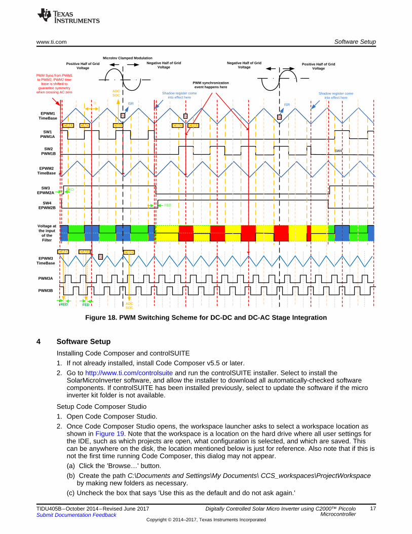
3.4 DC-DC and DC-AC IntegrationThe DC-DC stage is switched at 100 Khz and DC-AC stage at 50 Khz. The peripheral ADC and PWMs onthe C2000 device family have been designed to integrate multifrequency control loops and guaranteesampling at correct instances of the PWM waveform. However, as only one ADC is present (two sampleand holds), the multi rate ISRs must not conflict with the ADC resource at any instance. For this thephase, the shift mechanism of the PWMs on the ePWM peripheral is employed. Figure 18 illustrates thetiming diagram for configuring the EPWM for the inverter, and shows how to generate PWM waveforms forboth the positive and negative half of the sine wave.
xx
Positive Half of Grid Voltage
Negative Half of Grid Voltage
EPWM1TimeBase
SW3EPWM2A
SW4EPWM2B
SW1PWM1A
MicroInv Clamped Modulation
PWM synchronization event happens here
Z
SW4
CAU
EPWM2TimeBase
Voltage at the input
of the Filter
D
CAD
FED
RED
ISR
Shadow register come into effect here
SW2PWM1B
Positive Half of Grid Voltage
Negative Half of Grid Voltage
CBD CBU
Shadow register come into effect here
ISR
Z
PWM Sync from PWM1 to PWM2, PWM2 time
base is shifted to guarantee symmetry
when crossing AC zero
Z
EPWM3TimeBase
PWM3A
PWM3B
RED FED
CAD CAUZ
CBD
ADC SOC
CBD
ADC SOC
www.ti.com Software Setup
17TIDU405B–October 2014–Revised June 2017Submit Documentation Feedback
Copyright © 2014–2017, Texas Instruments Incorporated
Digitally Controlled Solar Micro Inverter using C2000™ PiccoloMicrocontroller
Figure 18. PWM Switching Scheme for DC-DC and DC-AC Stage Integration
4 Software SetupInstalling Code Composer and controlSUITE1. If not already installed, install Code Composer v5.5 or later.2. Go to http://www.ti.com/controlsuite and run the controlSUITE installer. Select to install the
SolarMicroInverter software, and allow the installer to download all automatically-checked softwarecomponents. If controlSUITE has been installed previously, select to update the software if the microinverter kit folder is not available.
Setup Code Composer Studio1. Open Code Composer Studio.2. Once Code Composer Studio opens, the workspace launcher asks to select a workspace location as
shown in Figure 19. Note that the workspace is a location on the hard drive where all user settings forthe IDE, such as which projects are open, what configuration is selected, and which are saved. Thiscan be anywhere on the disk, the location mentioned below is just for reference. Also note that if this isnot the first time running Code Composer, this dialog may not appear.(a) Click the 'Browse…' button.(b) Create the path C:\Documents and Settings\My Documents\ CCS_workspaces\ProjectWorkspace
by making new folders as necessary.(c) Uncheck the box that says 'Use this as the default and do not ask again.'
Software Setup www.ti.com
18 TIDU405B–October 2014–Revised June 2017Submit Documentation Feedback
Copyright © 2014–2017, Texas Instruments Incorporated
Digitally Controlled Solar Micro Inverter using C2000™ PiccoloMicrocontroller
(d) Click OK.
Figure 19. Opening a New Workspace
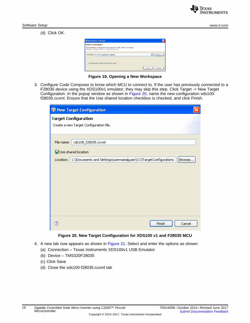
3. Configure Code Composer to know which MCU to connect to. If the user has previously connected to aF28035 device using the XDS100v1 emulator, they may skip this step. Click Target -> New TargetConfiguration. In the popup window as shown in Figure 20, name the new configuration xds100-f28035.ccxml. Ensure that the Use shared location checkbox is checked, and click Finish.
Figure 20. New Target Configuration for XDS100 v1 and F28035 MCU
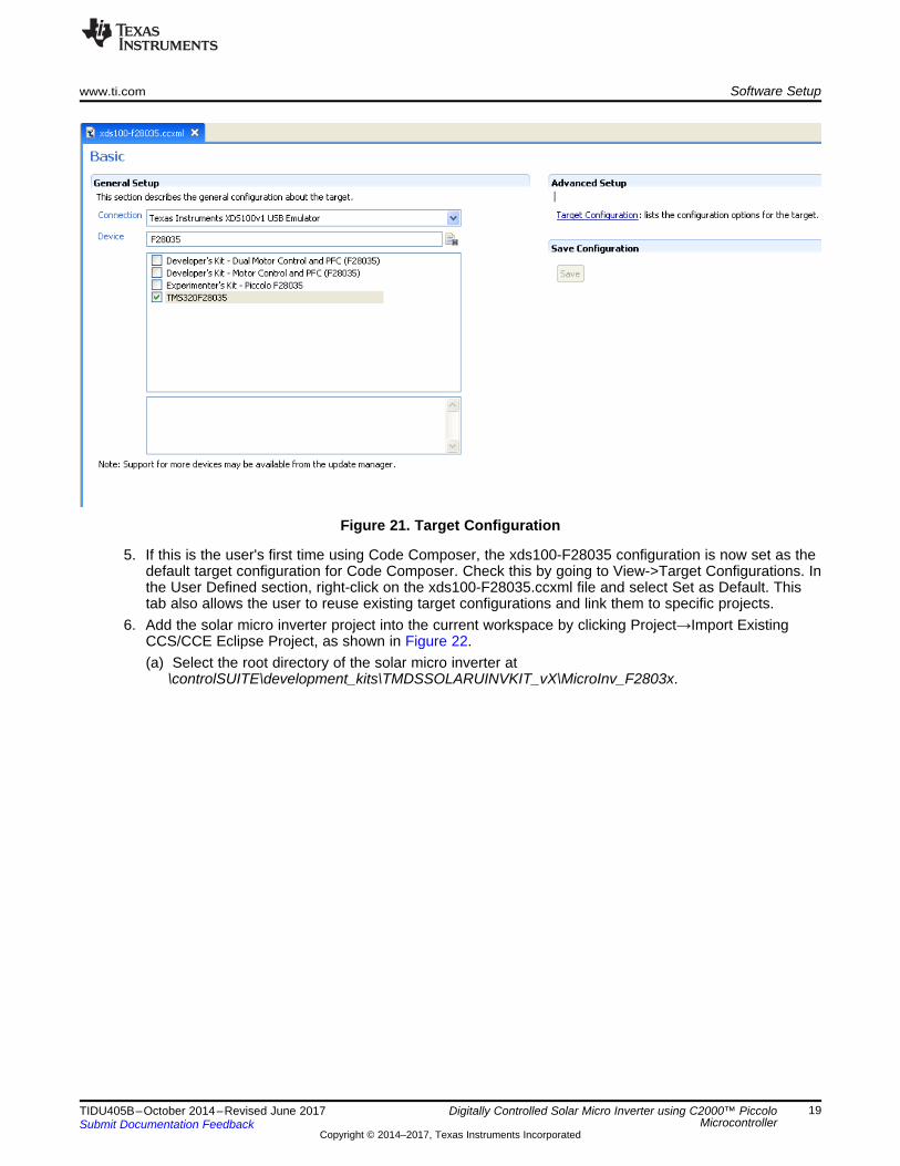
4. A new tab now appears as shown in Figure 21. Select and enter the options as shown:(a) Connection – Texas Instruments XDS100v1 USB Emulator(b) Device – TMS320F28035(c) Click Save(d) Close the xds100-f28035.ccxml tab
www.ti.com Software Setup
19TIDU405B–October 2014–Revised June 2017Submit Documentation Feedback
Copyright © 2014–2017, Texas Instruments Incorporated
Digitally Controlled Solar Micro Inverter using C2000™ PiccoloMicrocontroller
Figure 21. Target Configuration
5. If this is the user's first time using Code Composer, the xds100-F28035 configuration is now set as thedefault target configuration for Code Composer. Check this by going to View->Target Configurations. Inthe User Defined section, right-click on the xds100-F28035.ccxml file and select Set as Default. Thistab also allows the user to reuse existing target configurations and link them to specific projects.
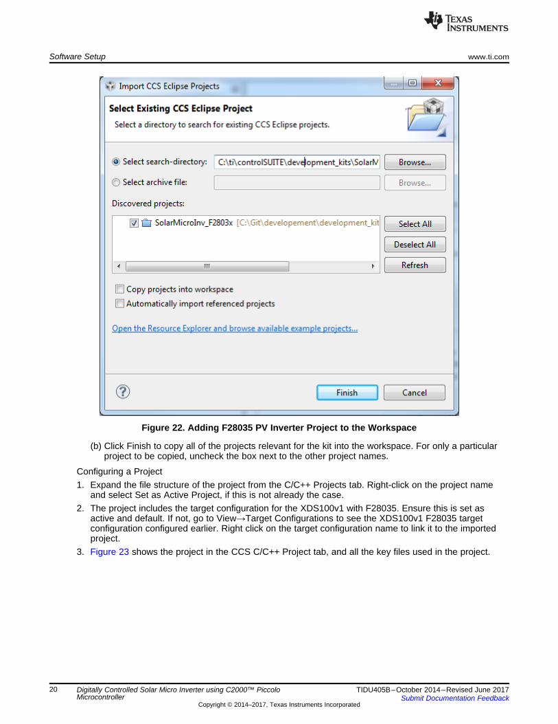
6. Add the solar micro inverter project into the current workspace by clicking Project→Import ExistingCCS/CCE Eclipse Project, as shown in Figure 22.(a) Select the root directory of the solar micro inverter at
\controlSUITE\development_kits\TMDSSOLARUINVKIT_vX\MicroInv_F2803x.
Software Setup www.ti.com
20 TIDU405B–October 2014–Revised June 2017Submit Documentation Feedback
Copyright © 2014–2017, Texas Instruments Incorporated
Digitally Controlled Solar Micro Inverter using C2000™ PiccoloMicrocontroller
Figure 22. Adding F28035 PV Inverter Project to the Workspace
(b) Click Finish to copy all of the projects relevant for the kit into the workspace. For only a particularproject to be copied, uncheck the box next to the other project names.
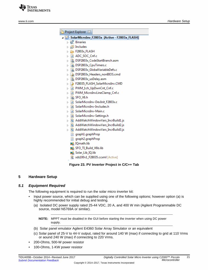
Configuring a Project1. Expand the file structure of the project from the C/C++ Projects tab. Right-click on the project name
and select Set as Active Project, if this is not already the case.2. The project includes the target configuration for the XDS100v1 with F28035. Ensure this is set as
active and default. If not, go to View→Target Configurations to see the XDS100v1 F28035 targetconfiguration configured earlier. Right click on the target configuration name to link it to the importedproject.
3. Figure 23 shows the project in the CCS C/C++ Project tab, and all the key files used in the project.
www.ti.com Hardware Setup
21TIDU405B–October 2014–Revised June 2017Submit Documentation Feedback
Copyright © 2014–2017, Texas Instruments Incorporated
Digitally Controlled Solar Micro Inverter using C2000™ PiccoloMicrocontroller
Figure 23. PV Inverter Project in C/C++ Tab
5 Hardware Setup
5.1 Equipment RequiredThe following equipment is required to run the solar micro inverter kit:• Input power source, which can be supplied using one of the following options; however option (a) is
highly recommended for initial debug and testing.(a) Isolated DC power supply rated 25-44 VDC, 20 A, and 400 W min (Agilent Programmable DC
source, model N5769A or similar).
NOTE: MPPT must be disabled in the GUI before starting the inverter when using DC powersupply.
(b) Solar panel emulator Agilent E4360 Solar Array Simulator or an equivalent(c) Solar panel of 25-V to 44-V output, rated for around 140 W (max) if connecting to grid at 110 Vrms
or aound 240 W (max) if connecting to 220 Vrms.• 200-Ohms, 500-W power resistor• 100-Ohms, 1-KW power resistor
Hardware Setup www.ti.com
22 TIDU405B–October 2014–Revised June 2017Submit Documentation Feedback
Copyright © 2014–2017, Texas Instruments Incorporated
Digitally Controlled Solar Micro Inverter using C2000™ PiccoloMicrocontroller
• 1000-Ohms 500-W power resistor
The following equipment should be connected to the micro inverter board to observe different voltagesand currents:• Volt-meters of up to 500-V input range• Oscilloscope of around 200-MHz bandwidth.• High volt differential probe, Tektronix P5205 or similar.• Current probe, Tektronix TCP202 or similar• Current meter for output AC current, up to 5-A (RMS) range• Current meter for input DC current, up to 12-A (DC) range
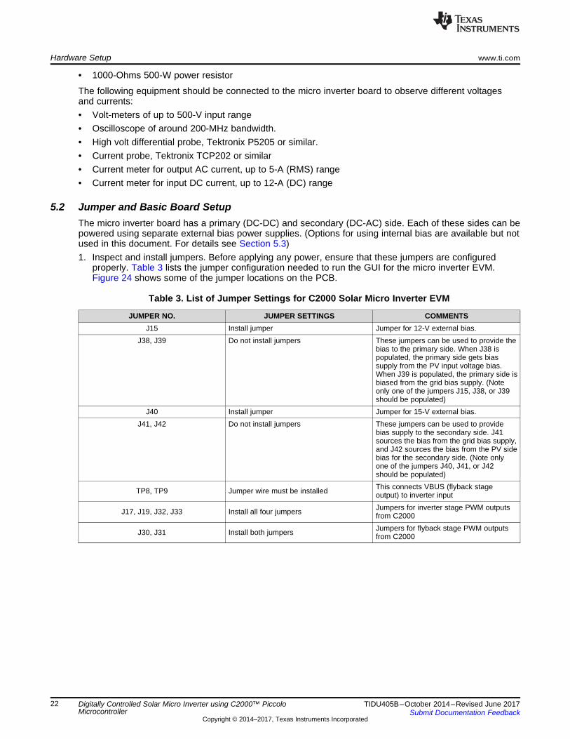
5.2 Jumper and Basic Board SetupThe micro inverter board has a primary (DC-DC) and secondary (DC-AC) side. Each of these sides can bepowered using separate external bias power supplies. (Options for using internal bias are available but notused in this document. For details see Section 5.3)1. Inspect and install jumpers. Before applying any power, ensure that these jumpers are configured
properly. Table 3 lists the jumper configuration needed to run the GUI for the micro inverter EVM.Figure 24 shows some of the jumper locations on the PCB.
Table 3. List of Jumper Settings for C2000 Solar Micro Inverter EVM
JUMPER NO. JUMPER SETTINGS COMMENTSJ15 Install jumper Jumper for 12-V external bias.
J38, J39 Do not install jumpers These jumpers can be used to provide thebias to the primary side. When J38 ispopulated, the primary side gets biassupply from the PV input voltage bias.When J39 is populated, the primary side isbiased from the grid bias supply. (Noteonly one of the jumpers J15, J38, or J39should be populated)
J40 Install jumper Jumper for 15-V external bias.J41, J42 Do not install jumpers These jumpers can be used to provide
bias supply to the secondary side. J41sources the bias from the grid bias supply,and J42 sources the bias from the PV sidebias for the secondary side. (Note onlyone of the jumpers J40, J41, or J42should be populated)
TP8, TP9 Jumper wire must be installed This connects VBUS (flyback stageoutput) to inverter input
J17, J19, J32, J33 Install all four jumpers Jumpers for inverter stage PWM outputsfrom C2000
J30, J31 Install both jumpers Jumpers for flyback stage PWM outputsfrom C2000
Solar uINVFlyback Stage
DC-DC
Solar uINVINV Stage
DC-AC
TP8,TP9
TP10
TP15
TP16
TP12
TP13
TMDSSOLARUINVKIT
12V External Bias Supply (Line and Neutral Connection Only)
15V External Bias Supply(Line and Neutral Connection Only)
www.ti.com Hardware Setup
23TIDU405B–October 2014–Revised June 2017Submit Documentation Feedback
Copyright © 2014–2017, Texas Instruments Incorporated
Digitally Controlled Solar Micro Inverter using C2000™ PiccoloMicrocontroller
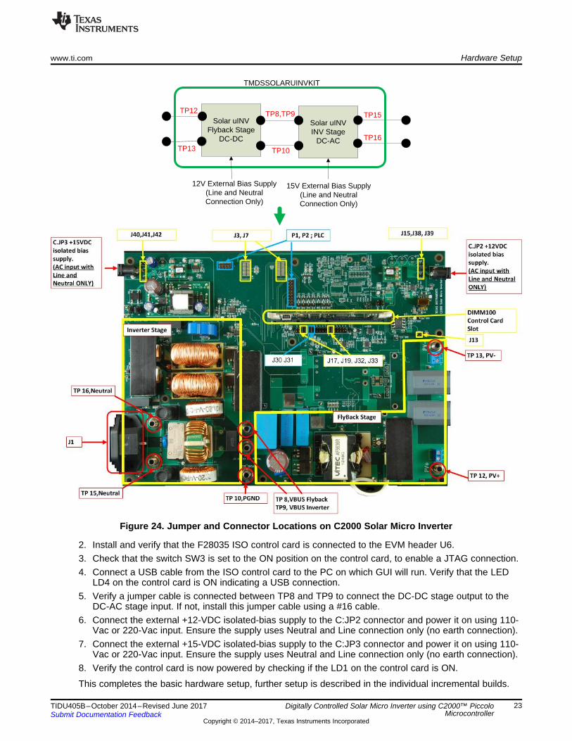
Figure 24. Jumper and Connector Locations on C2000 Solar Micro Inverter
2. Install and verify that the F28035 ISO control card is connected to the EVM header U6.3. Check that the switch SW3 is set to the ON position on the control card, to enable a JTAG connection.4. Connect a USB cable from the ISO control card to the PC on which GUI will run. Verify that the LED
LD4 on the control card is ON indicating a USB connection.5. Verify a jumper cable is connected between TP8 and TP9 to connect the DC-DC stage output to the
DC-AC stage input. If not, install this jumper cable using a #16 cable.6. Connect the external +12-VDC isolated-bias supply to the C:JP2 connector and power it on using 110-
Vac or 220-Vac input. Ensure the supply uses Neutral and Line connection only (no earth connection).7. Connect the external +15-VDC isolated-bias supply to the C:JP3 connector and power it on using 110-
Vac or 220-Vac input. Ensure the supply uses Neutral and Line connection only (no earth connection).8. Verify the control card is now powered by checking if the LD1 on the control card is ON.
This completes the basic hardware setup, further setup is described in the individual incremental builds.
Hardware Setup www.ti.com
24 TIDU405B–October 2014–Revised June 2017Submit Documentation Feedback
Copyright © 2014–2017, Texas Instruments Incorporated
Digitally Controlled Solar Micro Inverter using C2000™ PiccoloMicrocontroller
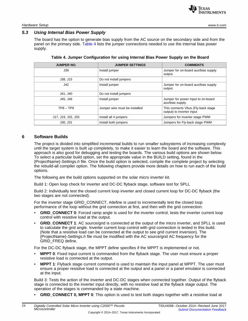
5.3 Using Internal Bias Power SupplyThe board has the option to generate bias supply from the AC source on the secondary side and from thepanel on the primary side. Table 4 lists the jumper connections needed to use the internal bias powersupply.
Table 4. Jumper Configuration for using Internal Bias Power Supply on the Board
JUMPER NO. JUMPER SETTINGS COMMENTSJ39 Install jumper Jumper for on-board aux/bias supply
output.J38, J15 Do not install jumpers
J42 Install jumper Jumper for on-board aux/bias supplyoutput.
J41, J40 Do not install jumpersJ45, J46 Install jumper Jumper for power input to on-board
aux/bias supply.TP8 – TP9 Jumper wire must be installed This connects Vbus (Fly-back stage
output) to inverter inputJ17, J19, J32, J33 Install all 4 jumpers Jumpers for inverter stage PWM
J30, J31 Install both jumpers Jumpers for Fly-back stage PWM
6 Software BuildsThe project is divided into simplified incremental builds to run smaller subsystems of increasing complexityuntil the target system is built up completely, to make it easier to learn the board and the software. Thisapproach is also good for debugging and testing the boards. The various build options are shown below.To select a particular build option, set the appropriate value in the BUILD setting, found in the{ProjectName}-Settings.h file. Once the build option is selected, compile the complete project by selectingthe rebuild-all compiler option. The following chapters provide more details on how to run each of the buildoptions.
The following are the build options supported on the solar micro inverter kit.
Build 1: Open loop check for inverter and DC-DC flyback stage, software test for SPLL
Build 2: Individually test the closed current loop inverter and closed current loop for DC-DC flyback (thetwo stages are not connected).
For the inverter stage GRID_CONNECT, #define is used to incrementally test the closed loopperformance of the loop without the grid connection at first, and then with the grid connection:• GRID_CONNECT 0: Forced ramp angle is used for the inverter control, tests the inverter current loop
control with resistive load at the output.• GRID_CONNECT 1: AC source/grid is connected at the output of the micro inverter, and SPLL is used
to calculate the grid angle. Inverter current loop control with grid connection is tested in this build.(Note that a resistive load can be connected at the output to see grid current inversion). The{ProjectName}-Settings.h file must be modified with the AC source/grid AC frequency for theGRID_FREQ define.
For the DC-DC flyback stage, the MPPT define specifies if the MPPT is implemented or not.• MPPT 0: Fixed input current is commanded from the flyback stage. The user must ensure a proper
resistive load is connected at the output.• MPPT 1: Flyback stage current command is used to maintain the input panel at MPPT. The user must
ensure a proper resistive load is connected at the output and a panel or a panel emulator is connectedat the input.
Build 3: Tests the action of the inverter and DC-DC stages when connected together. Output of the flybackstage is connected to the inverter input directly, with no resistive load at the flyback stage output. Theoperation of the stages is commanded by a state machine.• GRID_CONNECT 0, MPPT 0: This option is used to test both stages together with a resistive load at
Solar uINVFlyback Stage
DC Power Supply (Upto
50V DC)
Load(1K Ohms)
Volt Meter
TP12
TP13
TP8,TP9
TP10
www.ti.com Software Builds
25TIDU405B–October 2014–Revised June 2017Submit Documentation Feedback
Copyright © 2014–2017, Texas Instruments Incorporated
Digitally Controlled Solar Micro Inverter using C2000™ PiccoloMicrocontroller
the output of the inverter. This tests the board with a DC source at the input instead of a PV panelemulator.
• GRID_CONNECT 0, MPPT 1: This option tests the combined action of both stages and the statemachine when a resistive load is at the output and input is from a PV / PV emulator source.
• GRID_CONNECT 1, MPPT 0: This option tests both stages together with a grid connection at theoutput and a DC source at the input,instead of a PV panel emulator; therefore MPPT is disabled.
• GRID_CONNECT 1, MPPT 1: This option tests the combined action of both stages and the statemachine when the grid is connected at the inverter output. DC input is from a PV / PV emulator source,therefore MPPT is enabled. This is the full PV inverter system build.
All software files related to this C28x controlled Solar Explorer system, such as the main source files, ISRassembly files, and the project file for C framework, are located in the directory:…\controlSUITE\development_kits\TMDSSOLARUINVKIT_v100 \MicroInv_F2803x.
6.1 BUILD = 1
6.1.1 ObjectiveThe objectives of this build are:• Evaluate the PWM and ADC software driver modules• Verify the MOSFET gate driver, voltage, and current sensing circuit• Become familiar with the operation of Code Composer Studio (CCS)• Test the SPLL moduleUnder this build, the system runs in open loop for the inverter power stage and DCDC boost stage. Thesteps required for building and running a project are explained in the following sections.
6.1.2 OverviewThe software in Build1 is configured to quickly evaluate the PWM driver module and ADC drivers for theinverter and the flyback stage, by viewing the related waveforms on a scope, a multi meter, or on anexpressions window in CCS. The user can also observe the effect of changing the inverter modulationindex and flyback duty on the power stage through observing variables in the watch window.
6.1.3 Flyback Open Loop Check
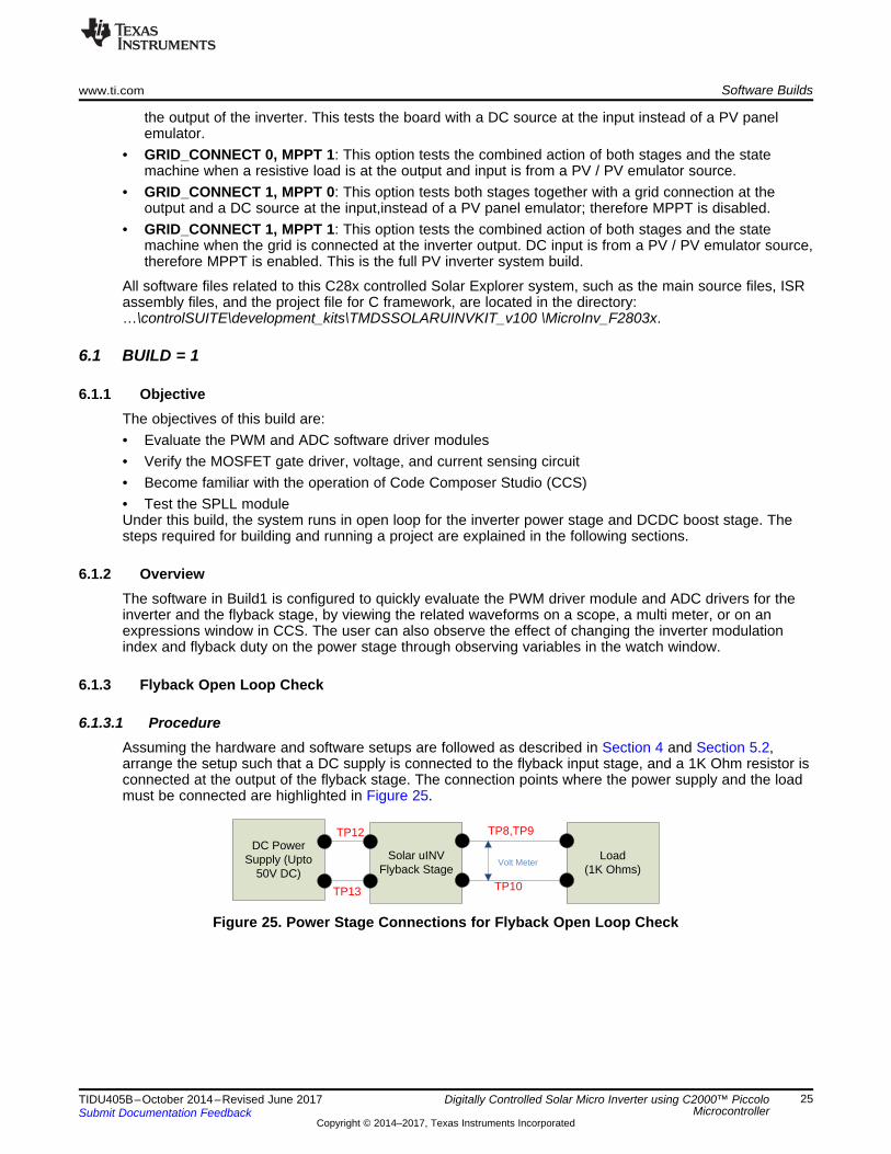
6.1.3.1 ProcedureAssuming the hardware and software setups are followed as described in Section 4 and Section 5.2,arrange the setup such that a DC supply is connected to the flyback input stage, and a 1K Ohm resistor isconnected at the output of the flyback stage. The connection points where the power supply and the loadmust be connected are highlighted in Figure 25.
Figure 25. Power Stage Connections for Flyback Open Loop Check
Vpv
Flyback StageIpv
DC Supply
P1B
P1A
I(P4A)
(P4B)
Vbus
.In
NOTCH_FLTR
.Out
Coeff
.In
NOTCH_FLTR
.Out
Coeff
Read ADC Values and scale
them to PU
pv_meas_cur_inst
pv_meas_vol_inst
MATH_EMAVG
.In.Out
Multiplier
MATH_EMAVG
.In.Out
Multiplier
Duty_flyback_pu Write to PWM registers
pv_meas_cur_avg
pv_meas_vol_avg
Load
Software Builds www.ti.com
26 TIDU405B–October 2014–Revised June 2017Submit Documentation Feedback
Copyright © 2014–2017, Texas Instruments Incorporated
Digitally Controlled Solar Micro Inverter using C2000™ PiccoloMicrocontroller
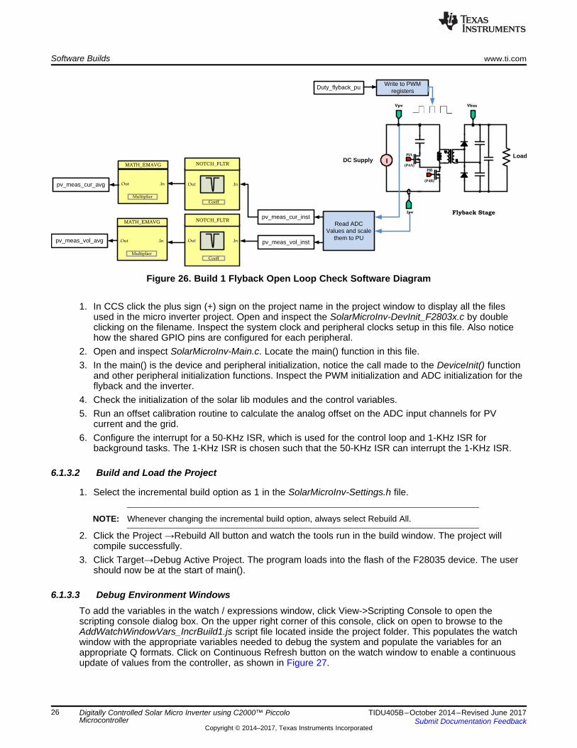
Figure 26. Build 1 Flyback Open Loop Check Software Diagram
1. In CCS click the plus sign (+) sign on the project name in the project window to display all the filesused in the micro inverter project. Open and inspect the SolarMicroInv-DevInit_F2803x.c by doubleclicking on the filename. Inspect the system clock and peripheral clocks setup in this file. Also noticehow the shared GPIO pins are configured for each peripheral.
2. Open and inspect SolarMicroInv-Main.c. Locate the main() function in this file.3. In the main() is the device and peripheral initialization, notice the call made to the DeviceInit() function
and other peripheral initialization functions. Inspect the PWM initialization and ADC initialization for theflyback and the inverter.
4. Check the initialization of the solar lib modules and the control variables.5. Run an offset calibration routine to calculate the analog offset on the ADC input channels for PV
current and the grid.6. Configure the interrupt for a 50-KHz ISR, which is used for the control loop and 1-KHz ISR for
background tasks. The 1-KHz ISR is chosen such that the 50-KHz ISR can interrupt the 1-KHz ISR.
6.1.3.2 Build and Load the Project
1. Select the incremental build option as 1 in the SolarMicroInv-Settings.h file.
NOTE: Whenever changing the incremental build option, always select Rebuild All.
2. Click the Project →Rebuild All button and watch the tools run in the build window. The project willcompile successfully.
3. Click Target→Debug Active Project. The program loads into the flash of the F28035 device. The usershould now be at the start of main().
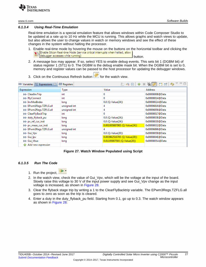
6.1.3.3 Debug Environment WindowsTo add the variables in the watch / expressions window, click View->Scripting Console to open thescripting console dialog box. On the upper right corner of this console, click on open to browse to theAddWatchWindowVars_IncrBuild1.js script file located inside the project folder. This populates the watchwindow with the appropriate variables needed to debug the system and populate the variables for anappropriate Q formats. Click on Continuous Refresh button on the watch window to enable a continuousupdate of values from the controller, as shown in Figure 27.
www.ti.com Software Builds
27TIDU405B–October 2014–Revised June 2017Submit Documentation Feedback
Copyright © 2014–2017, Texas Instruments Incorporated
Digitally Controlled Solar Micro Inverter using C2000™ PiccoloMicrocontroller
6.1.3.4 Using Real-Time EmulationReal-time emulation is a special emulation feature that allows windows within Code Composer Studio tobe updated at a rate up to 10 Hz while the MCU is running. This allows graphs and watch views to update,but also allows the user to change values in watch or memory windows and see the effect of thesechanges in the system without halting the processor.1. Enable real-time mode by hovering the mouse on the buttons on the horizontal toolbar and clicking the
button.2. A message box may appear. If so, select YES to enable debug events. This sets bit 1 (DGBM bit) of
status register 1 (ST1) to 0. The DGBM is the debug enable mask bit. When the DGBM bit is set to 0,memory and register values can be passed to the host processor for updating the debugger windows.
3. Click on the Continuous Refresh button for the watch view.
Figure 27. Watch Window Populated using Script
6.1.3.5 Run The Code
1. Run the project,2. In the watch view, check the value of Gui_Vpv, which will be the voltage at the input of the board.
Slowly raise this voltage to 30 V of the input power supply and see Gui_Vpv change as the inputvoltage is increased, as shown in Figure 28.
3. Clear the flyback stage trip by writing a 1 to the ClearFlyBacktrip variable. The EPwm3Regs.TZFLG.allgoes to zero as soon as the trip is cleared.
4. Enter a duty in the duty_flyback_pu field. Starting from 0.1, go up to 0.3. The watch window appearsas shown in Figure 28:
Solar uINVINV Stage
DC Power Supply HV (Upto 400V
DC)
LoadDifferential Voltage Probe
inviCurrent Probe
TP8,TP9
TP10
TP15
TP16
Software Builds www.ti.com
28 TIDU405B–October 2014–Revised June 2017Submit Documentation Feedback
Copyright © 2014–2017, Texas Instruments Incorporated
Digitally Controlled Solar Micro Inverter using C2000™ PiccoloMicrocontroller
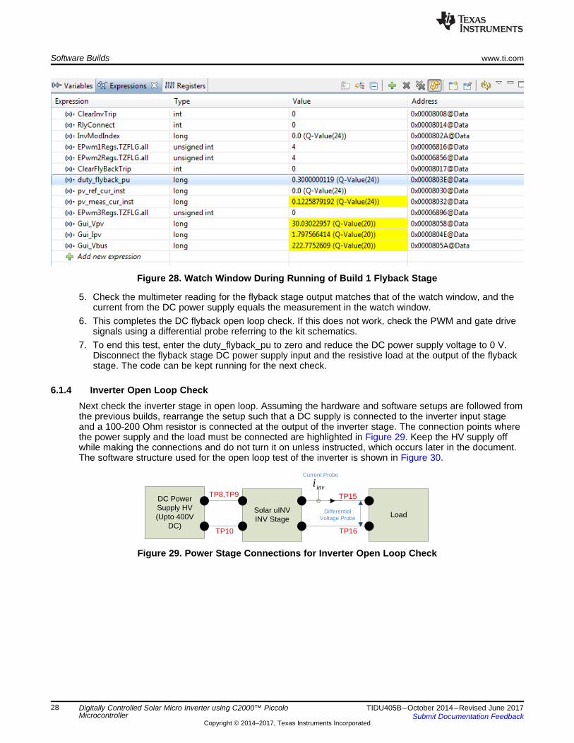
Figure 28. Watch Window During Running of Build 1 Flyback Stage
5. Check the multimeter reading for the flyback stage output matches that of the watch window, and thecurrent from the DC power supply equals the measurement in the watch window.
6. This completes the DC flyback open loop check. If this does not work, check the PWM and gate drivesignals using a differential probe referring to the kit schematics.
7. To end this test, enter the duty_flyback_pu to zero and reduce the DC power supply voltage to 0 V.Disconnect the flyback stage DC power supply input and the resistive load at the output of the flybackstage. The code can be kept running for the next check.
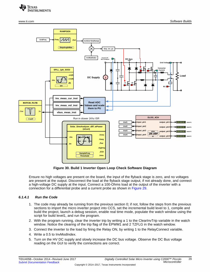
6.1.4 Inverter Open Loop CheckNext check the inverter stage in open loop. Assuming the hardware and software setups are followed fromthe previous builds, rearrange the setup such that a DC supply is connected to the inverter input stageand a 100-200 Ohm resistor is connected at the output of the inverter stage. The connection points wherethe power supply and the load must be connected are highlighted in Figure 29. Keep the HV supply offwhile making the connections and do not turn it on unless instructed, which occurs later in the document.The software structure used for the open loop test of the inverter is shown in Figure 30.
Figure 29. Power Stage Connections for Inverter Open Loop Check
Inverter DC Bus Feedback DC bus
1A
Grid Voltage
Converter Current
1B
2A 2B
R1
InvSine=Sin(Ramp)
Read ADC Values and scale
them to PU
inv_meas_cur_inst
inv_meas_vol_inst
vbus_meas_inst
.cos(�).Vin
SPLL_1ph_SOGI
wn
.(�)
.sin(�)
InvModIndex
duty_inv_pu
DLOG_4CH
input_ptr1 output_ptr1
sizetrig_valuepre_scal
ar
DBUFF1
output_ptr2 DBUFF2
output_ptr3 DBUFF3
output_ptr4 DBUFF4
input_ptr2
input_ptr3
input_ptr4
.Freq
RAMPGEN
StepAngleMax
.OutGridFreq
dval1
dval2
dval3
dval4
.In
NOTCH_FLTR
.Out
Coeff
.Vrms.Vin
Solar_SineAnalyzer_diff_wPower(struct)
SampleFreqThreshold
.Vavg
.Sigfreq
.ZCD
T=1/f
.Iin .Pwr
.Irms
Run in slower 1Khz ISR
LoadDC Supply I
www.ti.com Software Builds
29TIDU405B–October 2014–Revised June 2017Submit Documentation Feedback
Copyright © 2014–2017, Texas Instruments Incorporated
Digitally Controlled Solar Micro Inverter using C2000™ PiccoloMicrocontroller
Figure 30. Build 1 Inverter Open Loop Check Software Diagram
Ensure no high voltages are present on the board, the input of the flyback stage is zero, and no voltagesare present at the output. Disconnect the load at the flyback stage output, if not already done, and connecta high-voltage DC supply at the input. Connect a 100-Ohms load at the output of the inverter with aconnection for a differential probe and a current probe as shown in Figure 29.
6.1.4.1 Run the Code
1. The code may already be running from the previous section 0; if not, follow the steps from the previoussections to import the micro inverter project into CCS, set the incremental build level to 1, compile andbuild the project, launch a debug session, enable real time mode, populate the watch window using thescript for build level1, and run the program.
2. With the program running, clear the inverter trip by writing a 1 to the ClearInvTrip variable in the watchwindow. Notice the clearing of the trip flag of the EPWM1 and 2 TZFLG in the watch window.
3. Connect the inverter to the load by firing the Relay ON, by writing 1 to the RelayConnect variable.4. Write a 0.5 to InvModIndex.5. Turn on the HV DC supply and slowly increase the DC bus voltage. Observe the DC Bus voltage
reading on the GUI to verify the connections are correct.
Software Builds www.ti.com
30 TIDU405B–October 2014–Revised June 2017Submit Documentation Feedback
Copyright © 2014–2017, Texas Instruments Incorporated
Digitally Controlled Solar Micro Inverter using C2000™ PiccoloMicrocontroller
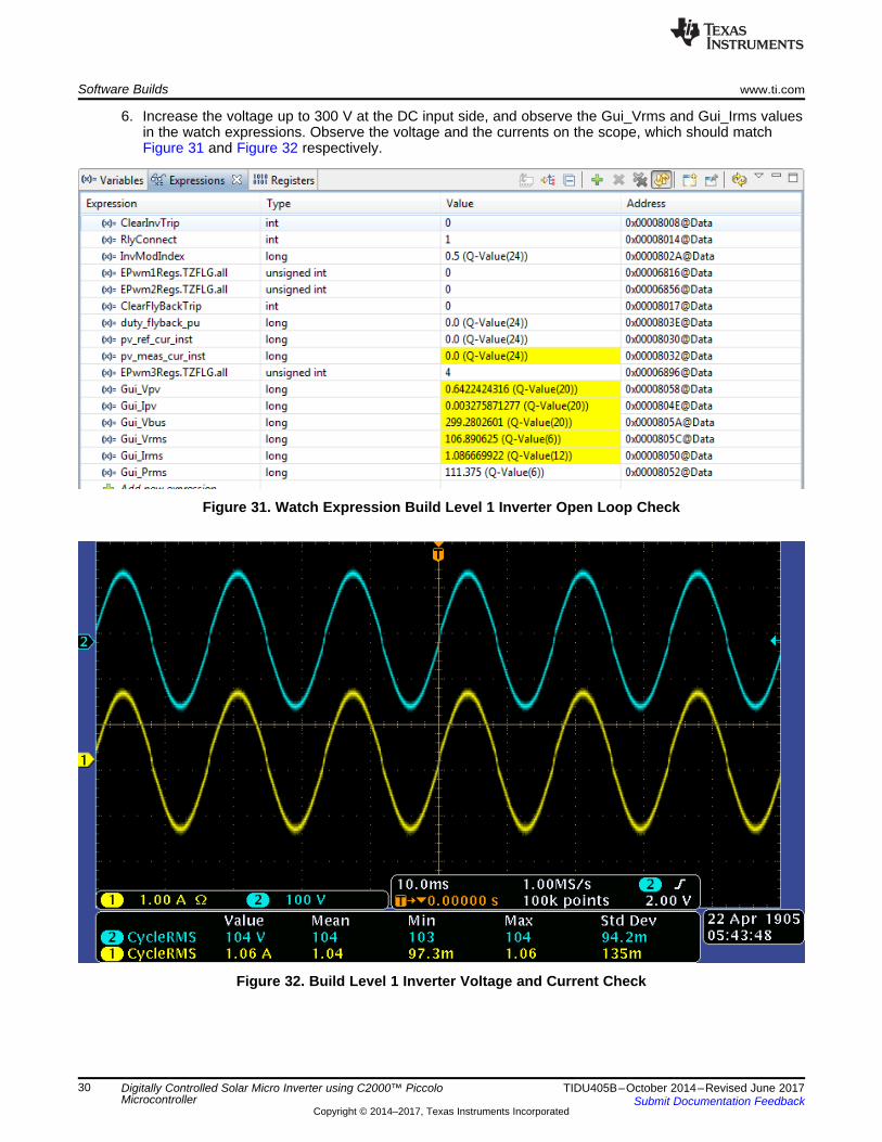
6. Increase the voltage up to 300 V at the DC input side, and observe the Gui_Vrms and Gui_Irms valuesin the watch expressions. Observe the voltage and the currents on the scope, which should matchFigure 31 and Figure 32 respectively.
Figure 31. Watch Expression Build Level 1 Inverter Open Loop Check
Figure 32. Build Level 1 Inverter Voltage and Current Check
www.ti.com Software Builds
31TIDU405B–October 2014–Revised June 2017Submit Documentation Feedback
Copyright © 2014–2017, Texas Instruments Incorporated
Digitally Controlled Solar Micro Inverter using C2000™ PiccoloMicrocontroller
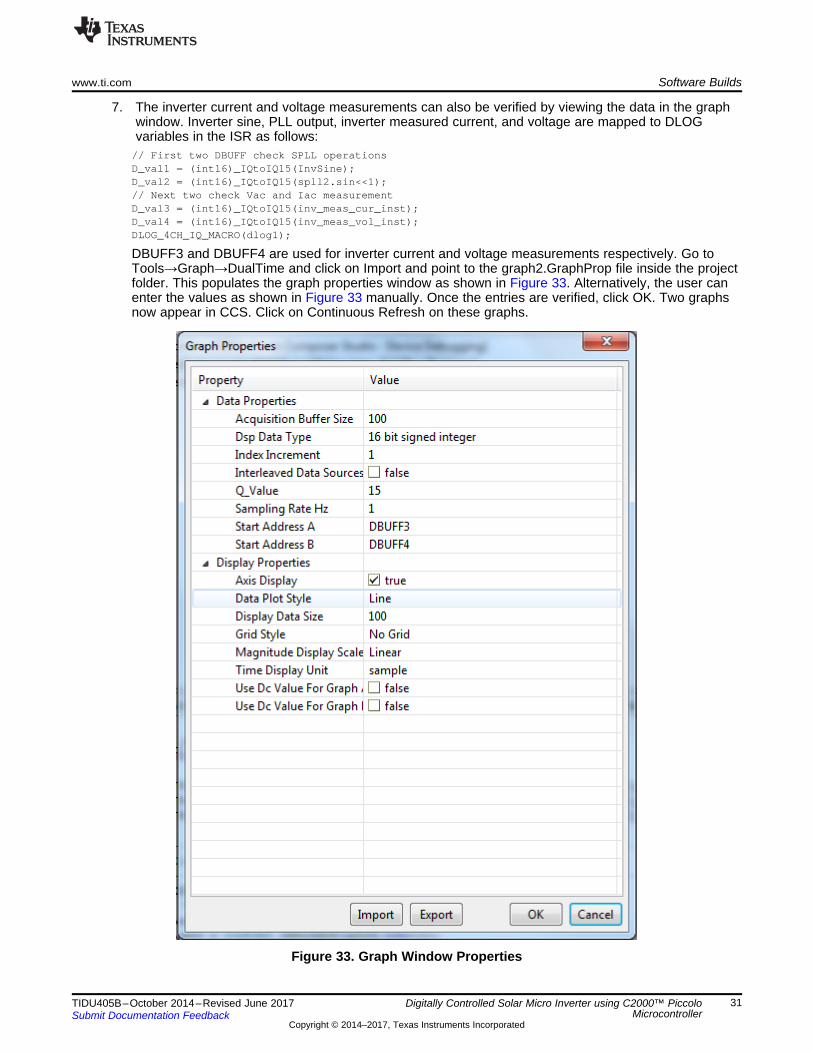
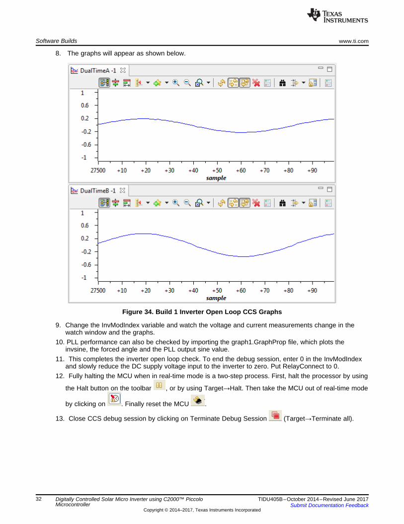
7. The inverter current and voltage measurements can also be verified by viewing the data in the graphwindow. Inverter sine, PLL output, inverter measured current, and voltage are mapped to DLOGvariables in the ISR as follows:
// First two DBUFF check SPLL operationsD_val1 = (int16)_IQtoIQ15(InvSine);D_val2 = (int16)_IQtoIQ15(spll2.sin<<1);// Next two check Vac and Iac measurementD_val3 = (int16)_IQtoIQ15(inv_meas_cur_inst);D_val4 = (int16)_IQtoIQ15(inv_meas_vol_inst);DLOG_4CH_IQ_MACRO(dlog1);
DBUFF3 and DBUFF4 are used for inverter current and voltage measurements respectively. Go toTools→Graph→DualTime and click on Import and point to the graph2.GraphProp file inside the projectfolder. This populates the graph properties window as shown in Figure 33. Alternatively, the user canenter the values as shown in Figure 33 manually. Once the entries are verified, click OK. Two graphsnow appear in CCS. Click on Continuous Refresh on these graphs.
Figure 33. Graph Window Properties
Software Builds www.ti.com
32 TIDU405B–October 2014–Revised June 2017Submit Documentation Feedback
Copyright © 2014–2017, Texas Instruments Incorporated
Digitally Controlled Solar Micro Inverter using C2000™ PiccoloMicrocontroller
8. The graphs will appear as shown below.
Figure 34. Build 1 Inverter Open Loop CCS Graphs
9. Change the InvModIndex variable and watch the voltage and current measurements change in thewatch window and the graphs.
10. PLL performance can also be checked by importing the graph1.GraphProp file, which plots theinvsine, the forced angle and the PLL output sine value.
11. This completes the inverter open loop check. To end the debug session, enter 0 in the InvModIndexand slowly reduce the DC supply voltage input to the inverter to zero. Put RelayConnect to 0.
12. Fully halting the MCU when in real-time mode is a two-step process. First, halt the processor by using
the Halt button on the toolbar , or by using Target→Halt. Then take the MCU out of real-time mode
by clicking on . Finally reset the MCU .
13. Close CCS debug session by clicking on Terminate Debug Session (Target→Terminate all).
Vpv
Flyback StageIpv
DC Supply
P1B
P1A
I(P4A)
(P4B)
Vbus
.In
NOTCH_FLTR
.Out
Coeff
.In
NOTCH_FLTR
.Out
Coeff
Read ADC Values and scale
them to PU
pv_meas_cur_inst
.Out.Ref
.Fdbk
CNTL_2P2Z
DBUFFCoef
pv_meas_vol_inst
MATH_EMAVG
.In.Out
Multiplier
MATH_EMAVG
.In.Out
Multiplier
pv_ref_cur_instDuty_flyback_pu
Write to PWM registers
pv_meas_cur_avg
pv_meas_vol_avg
Load
Solar uINVFlyback Stage
DC Power Supply (Upto
50V DC)
Load(Appropriate
Value ~500Ohms)
Volt Meter
TP12
TP13
TP8,TP9
TP10
pviCurrent Probe
www.ti.com Software Builds
33TIDU405B–October 2014–Revised June 2017Submit Documentation Feedback
Copyright © 2014–2017, Texas Instruments Incorporated
Digitally Controlled Solar Micro Inverter using C2000™ PiccoloMicrocontroller
6.2 Build = 2
6.2.1 ObjectiveThe objective of this build is to run a closed current loop individually for the flyback and inverter stage.MPPT is tested for the flyback stage, and grid-connected current control is tested for the inverter stageindividually.
6.2.2 OverviewThe software in Build2 is configured to quickly evaluate the closed current loop performance of the flybackand the inverter stage. The steps required for building and running a project are explained in the followingsections.
6.2.3 Flyback Closed Current Loop without MPPT
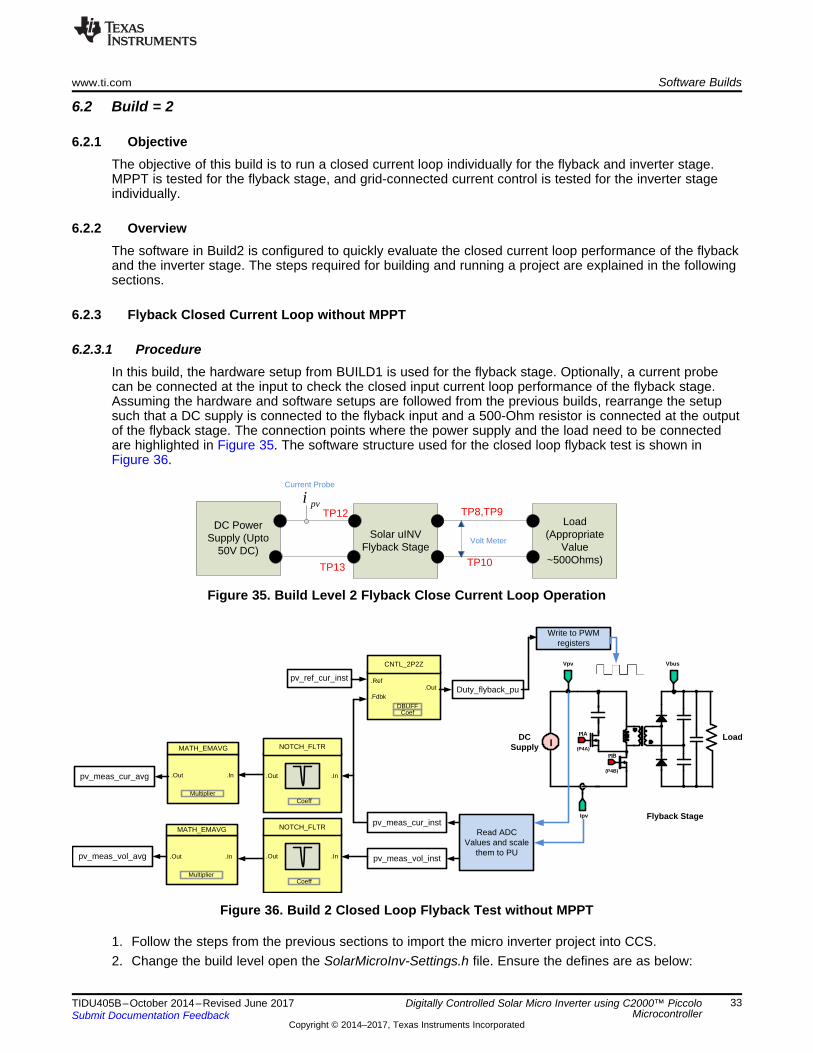
6.2.3.1 ProcedureIn this build, the hardware setup from BUILD1 is used for the flyback stage. Optionally, a current probecan be connected at the input to check the closed input current loop performance of the flyback stage.Assuming the hardware and software setups are followed from the previous builds, rearrange the setupsuch that a DC supply is connected to the flyback input and a 500-Ohm resistor is connected at the outputof the flyback stage. The connection points where the power supply and the load need to be connectedare highlighted in Figure 35. The software structure used for the closed loop flyback test is shown inFigure 36.
Figure 35. Build Level 2 Flyback Close Current Loop Operation
Figure 36. Build 2 Closed Loop Flyback Test without MPPT
1. Follow the steps from the previous sections to import the micro inverter project into CCS.2. Change the build level open the SolarMicroInv-Settings.h file. Ensure the defines are as below:
Software Builds www.ti.com
34 TIDU405B–October 2014–Revised June 2017Submit Documentation Feedback
Copyright © 2014–2017, Texas Instruments Incorporated
Digitally Controlled Solar Micro Inverter using C2000™ PiccoloMicrocontroller
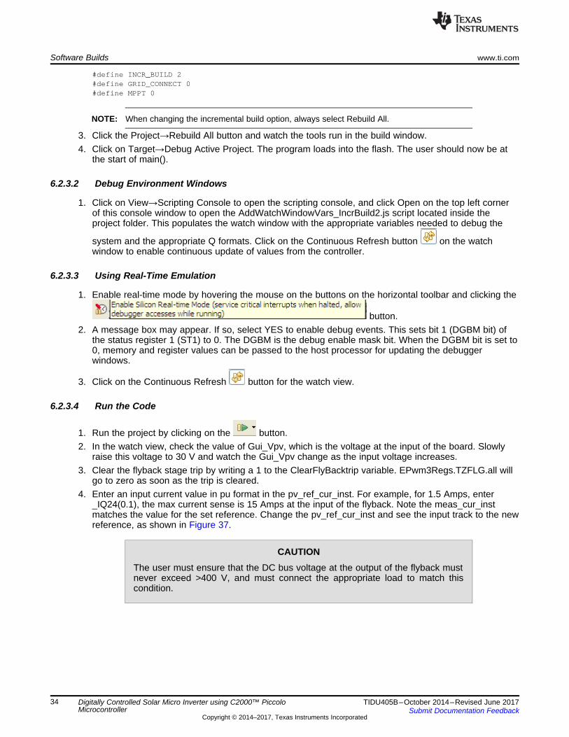
#define INCR_BUILD 2#define GRID_CONNECT 0#define MPPT 0
NOTE: When changing the incremental build option, always select Rebuild All.
3. Click the Project→Rebuild All button and watch the tools run in the build window.4. Click on Target→Debug Active Project. The program loads into the flash. The user should now be at
the start of main().
6.2.3.2 Debug Environment Windows
1. Click on View→Scripting Console to open the scripting console, and click Open on the top left cornerof this console window to open the AddWatchWindowVars_IncrBuild2.js script located inside theproject folder. This populates the watch window with the appropriate variables needed to debug the
system and the appropriate Q formats. Click on the Continuous Refresh button on the watchwindow to enable continuous update of values from the controller.
6.2.3.3 Using Real-Time Emulation
1. Enable real-time mode by hovering the mouse on the buttons on the horizontal toolbar and clicking the
button.2. A message box may appear. If so, select YES to enable debug events. This sets bit 1 (DGBM bit) of
the status register 1 (ST1) to 0. The DGBM is the debug enable mask bit. When the DGBM bit is set to0, memory and register values can be passed to the host processor for updating the debuggerwindows.
3. Click on the Continuous Refresh button for the watch view.
6.2.3.4 Run the Code
1. Run the project by clicking on the button.2. In the watch view, check the value of Gui_Vpv, which is the voltage at the input of the board. Slowly
raise this voltage to 30 V and watch the Gui_Vpv change as the input voltage increases.3. Clear the flyback stage trip by writing a 1 to the ClearFlyBacktrip variable. EPwm3Regs.TZFLG.all will
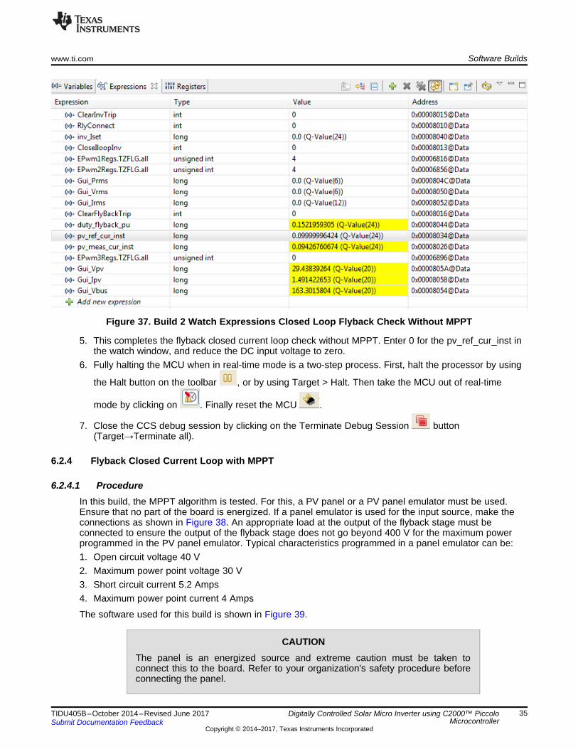
go to zero as soon as the trip is cleared.4. Enter an input current value in pu format in the pv_ref_cur_inst. For example, for 1.5 Amps, enter
_IQ24(0.1), the max current sense is 15 Amps at the input of the flyback. Note the meas_cur_instmatches the value for the set reference. Change the pv_ref_cur_inst and see the input track to the newreference, as shown in Figure 37.
CAUTIONThe user must ensure that the DC bus voltage at the output of the flyback mustnever exceed >400 V, and must connect the appropriate load to match thiscondition.
www.ti.com Software Builds
35TIDU405B–October 2014–Revised June 2017Submit Documentation Feedback
Copyright © 2014–2017, Texas Instruments Incorporated
Digitally Controlled Solar Micro Inverter using C2000™ PiccoloMicrocontroller
Figure 37. Build 2 Watch Expressions Closed Loop Flyback Check Without MPPT
5. This completes the flyback closed current loop check without MPPT. Enter 0 for the pv_ref_cur_inst inthe watch window, and reduce the DC input voltage to zero.
6. Fully halting the MCU when in real-time mode is a two-step process. First, halt the processor by using
the Halt button on the toolbar , or by using Target > Halt. Then take the MCU out of real-time
mode by clicking on . Finally reset the MCU .
7. Close the CCS debug session by clicking on the Terminate Debug Session button(Target→Terminate all).
6.2.4 Flyback Closed Current Loop with MPPT
6.2.4.1 ProcedureIn this build, the MPPT algorithm is tested. For this, a PV panel or a PV panel emulator must be used.Ensure that no part of the board is energized. If a panel emulator is used for the input source, make theconnections as shown in Figure 38. An appropriate load at the output of the flyback stage must beconnected to ensure the output of the flyback stage does not go beyond 400 V for the maximum powerprogrammed in the PV panel emulator. Typical characteristics programmed in a panel emulator can be:1. Open circuit voltage 40 V2. Maximum power point voltage 30 V3. Short circuit current 5.2 Amps4. Maximum power point current 4 Amps
The software used for this build is shown in Figure 39.
CAUTIONThe panel is an energized source and extreme caution must be taken toconnect this to the board. Refer to your organization's safety procedure beforeconnecting the panel.
Vpv
Flyback StageIpv
PV
P1B
P1A
I(P4A)
(P4B)
Vbus
.In
NOTCH_FLTR
.Out
Coeff
.In
NOTCH_FLTR
.Out
Coeff
Read ADC Values and scale
them to PU
pv_meas_cur_inst
pv_meas_vol_inst
MATH_EMAVG
.In.Out
Multiplier
MATH_EMAVG
.In.Out
Multiplier
Write to PWM registers
pv_meas_vol_avg
.Vpv
MPPT_INCC_I
StepSize
.ImppOut
.Ipv.Out
.Ref
.Fdbk
CNTL_2P2Z
DBUFFCoef
pv_ref_cur_instDuty_flyback_pu
Run in slower 1Khz ISR
pv_meas_cur_avg
Load
Solar uINVFlyback Stage
PV Panel Emulator /PV Panel
(Upto 250W)
Load(Appropriate Load for the
Panel Rating)
Volt Meter
TP12
TP13
TP8,TP9
TP10
Software Builds www.ti.com
36 TIDU405B–October 2014–Revised June 2017Submit Documentation Feedback
Copyright © 2014–2017, Texas Instruments Incorporated
Digitally Controlled Solar Micro Inverter using C2000™ PiccoloMicrocontroller
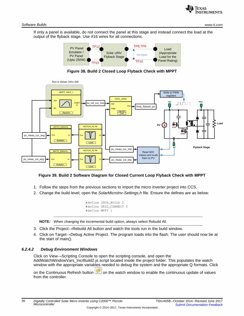
If only a panel is available, do not connect the panel at this stage and instead connect the load at theoutput of the flyback stage. Use #16 wires for all connections.
Figure 38. Build 2 Closed Loop Flyback Check with MPPT
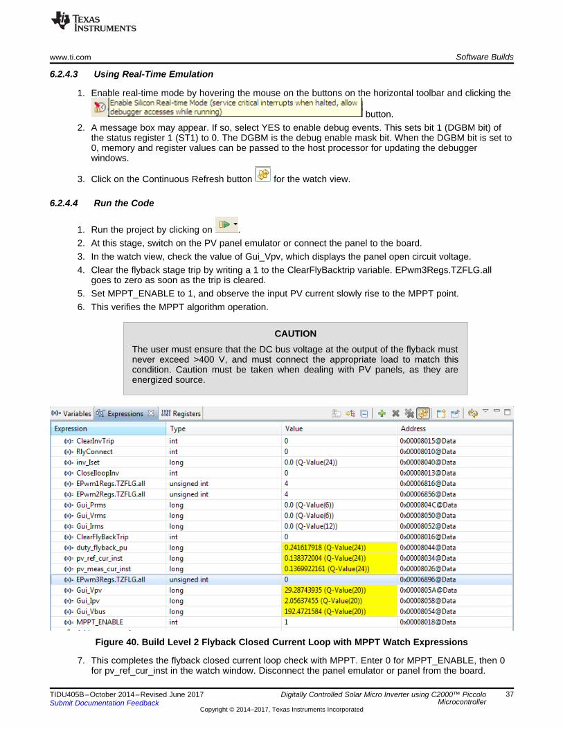
Figure 39. Build 2 Software Diagram for Closed Current Loop Flyback Check with MPPT
1. Follow the steps from the previous sections to import the micro inverter project into CCS.2. Change the build level; open the SolarMicroInv-Settings.h file. Ensure the defines are as below:
#define INCR_BUILD 2#define GRID_CONNECT 0#define MPPT 1
NOTE: When changing the incremental build option, always select Rebuild All.
3. Click the Project→Rebuild All button and watch the tools run in the build window.4. Click on Target→Debug Active Project. The program loads into the flash. The user should now be at
the start of main().
6.2.4.2 Debug Environment WindowsClick on View→Scripting Console to open the scripting console, and open theAddWatchWindowVars_IncrBuild2.js script located inside the project folder. This populates the watchwindow with the appropriate variables needed to debug the system and the appropriate Q formats. Click
on the Continuous Refresh button on the watch window to enable the continuous update of valuesfrom the controller.
www.ti.com Software Builds
37TIDU405B–October 2014–Revised June 2017Submit Documentation Feedback
Copyright © 2014–2017, Texas Instruments Incorporated
Digitally Controlled Solar Micro Inverter using C2000™ PiccoloMicrocontroller
6.2.4.3 Using Real-Time Emulation
1. Enable real-time mode by hovering the mouse on the buttons on the horizontal toolbar and clicking the
button.2. A message box may appear. If so, select YES to enable debug events. This sets bit 1 (DGBM bit) of
the status register 1 (ST1) to 0. The DGBM is the debug enable mask bit. When the DGBM bit is set to0, memory and register values can be passed to the host processor for updating the debuggerwindows.
3. Click on the Continuous Refresh button for the watch view.
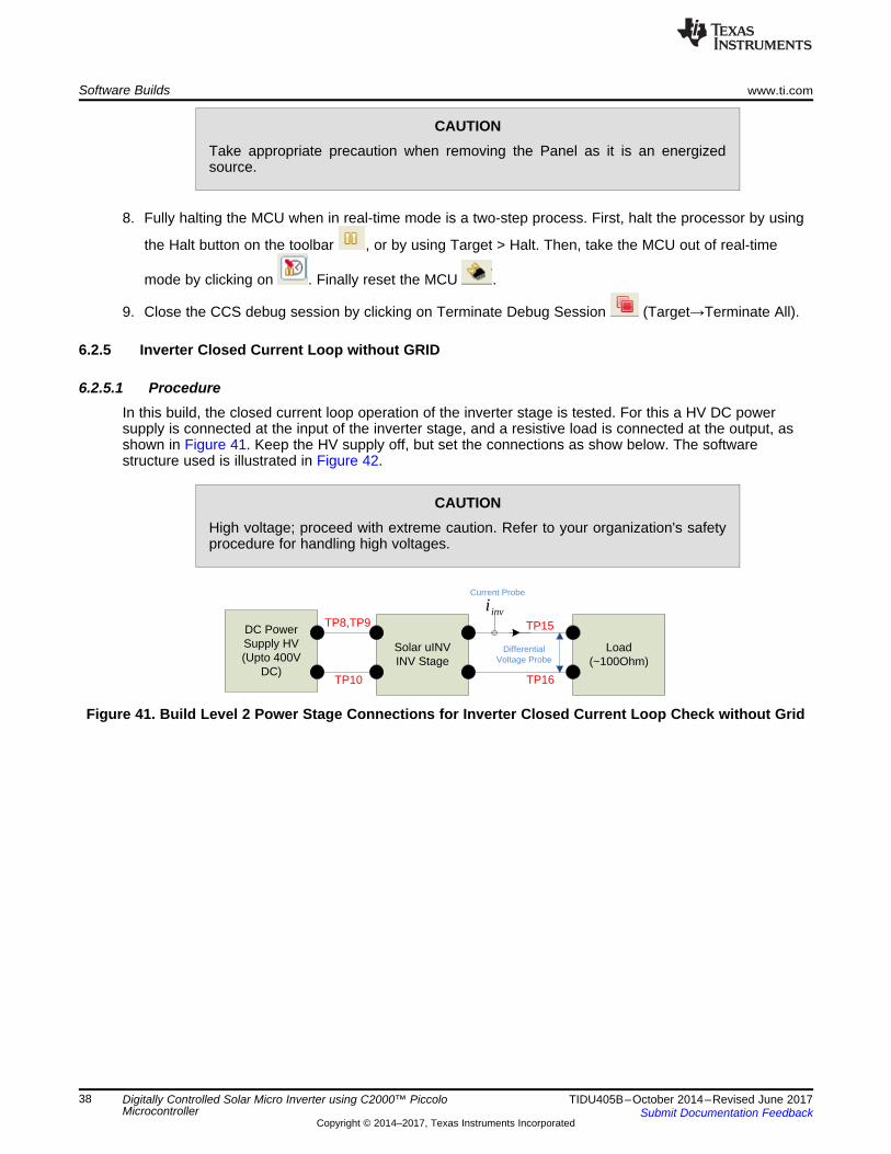
6.2.4.4 Run the Code
1. Run the project by clicking on .2. At this stage, switch on the PV panel emulator or connect the panel to the board.3. In the watch view, check the value of Gui_Vpv, which displays the panel open circuit voltage.4. Clear the flyback stage trip by writing a 1 to the ClearFlyBacktrip variable. EPwm3Regs.TZFLG.all
goes to zero as soon as the trip is cleared.5. Set MPPT_ENABLE to 1, and observe the input PV current slowly rise to the MPPT point.6. This verifies the MPPT algorithm operation.
CAUTIONThe user must ensure that the DC bus voltage at the output of the flyback mustnever exceed >400 V, and must connect the appropriate load to match thiscondition. Caution must be taken when dealing with PV panels, as they areenergized source.
Figure 40. Build Level 2 Flyback Closed Current Loop with MPPT Watch Expressions
7. This completes the flyback closed current loop check with MPPT. Enter 0 for MPPT_ENABLE, then 0for pv_ref_cur_inst in the watch window. Disconnect the panel emulator or panel from the board.
Solar uINVINV Stage
DC Power Supply HV (Upto 400V
DC)
Load(~100Ohm)
Differential Voltage Probe
inviCurrent Probe
TP8,TP9
TP10
TP15
TP16
Software Builds www.ti.com
38 TIDU405B–October 2014–Revised June 2017Submit Documentation Feedback
Copyright © 2014–2017, Texas Instruments Incorporated
Digitally Controlled Solar Micro Inverter using C2000™ PiccoloMicrocontroller
CAUTIONTake appropriate precaution when removing the Panel as it is an energizedsource.
8. Fully halting the MCU when in real-time mode is a two-step process. First, halt the processor by using
the Halt button on the toolbar , or by using Target > Halt. Then, take the MCU out of real-time
mode by clicking on . Finally reset the MCU .
9. Close the CCS debug session by clicking on Terminate Debug Session (Target→Terminate All).
6.2.5 Inverter Closed Current Loop without GRID
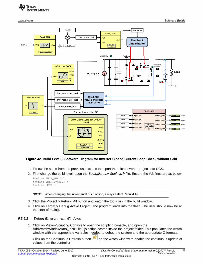
6.2.5.1 ProcedureIn this build, the closed current loop operation of the inverter stage is tested. For this a HV DC powersupply is connected at the input of the inverter stage, and a resistive load is connected at the output, asshown in Figure 41. Keep the HV supply off, but set the connections as show below. The softwarestructure used is illustrated in Figure 42.
CAUTIONHigh voltage; proceed with extreme caution. Refer to your organization's safetyprocedure for handling high voltages.
Figure 41. Build Level 2 Power Stage Connections for Inverter Closed Current Loop Check without Grid
Inverter DC Bus Feedback DC bus
1A
Grid Voltage
Converter Current
1B
2A 2B
R1
Inv_Iset
Read ADC Values and scale
them to PU
inv_meas_cur_inst
inv_meas_vol_inst
vbus_meas_inst
.cos(�).Vin
SPLL_1ph_SOGI
wn
.(�)
.sin(�)
InvSine=Sin(Ramp)
DLOG_4CH
input_ptr1 output_ptr1
sizetrig_valuepre_scal
ar
DBUFF1
output_ptr2 DBUFF2
output_ptr3 DBUFF3
output_ptr4 DBUFF4
input_ptr2
input_ptr3
input_ptr4
.Freq
RAMPGEN
StepAngleMax
.OutGridFreq
dval1
dval2
dval3
dval4
.In
NOTCH_FLTR
.Out
Coeff
.Vrms.Vin
Solar_SineAnalyzer_diff_wPower(struct)
SampleFreqThreshold
.Vavg
.Sigfreq
.ZCD
T=1/f
.Iin .Pwr
.Irms
Run in slower 1Khz ISR
LoadDC Supply I
Feedback Linearization
duty_inv_pu
.Out.Ref
.Fdbk
CNTL_3P3Z
DBUFFCoef
inv_ref_cur_inst
www.ti.com Software Builds
39TIDU405B–October 2014–Revised June 2017Submit Documentation Feedback
Copyright © 2014–2017, Texas Instruments Incorporated
Digitally Controlled Solar Micro Inverter using C2000™ PiccoloMicrocontroller
Figure 42. Build Level 2 Software Diagram for Inverter Closed Current Loop Check without Grid
1. Follow the steps from the previous sections to import the micro inverter project into CCS.2. First change the build level; open the SolarMicroInv-Settings.h file. Ensure the #defines are as below:
#define INCR_BUILD 2#define GRID_CONNECT 0#define MPPT 0
NOTE: When changing the incremental build option, always select Rebuild All.
3. Click the Project > Rebuild All button and watch the tools run in the build window.4. Click on Target > Debug Active Project. The program loads into the flash. The user should now be at
the start of main().
6.2.5.2 Debug Environment Windows
1. Click on View→Scripting Console to open the scripting console, and open theAddWatchWindowVars_IncrBuild2.js script located inside the project folder. This populates the watchwindow with the appropriate variables needed to debug the system and the appropriate Q formats.
Click on the Continuous Refresh button on the watch window to enable the continuous update ofvalues from the controller.
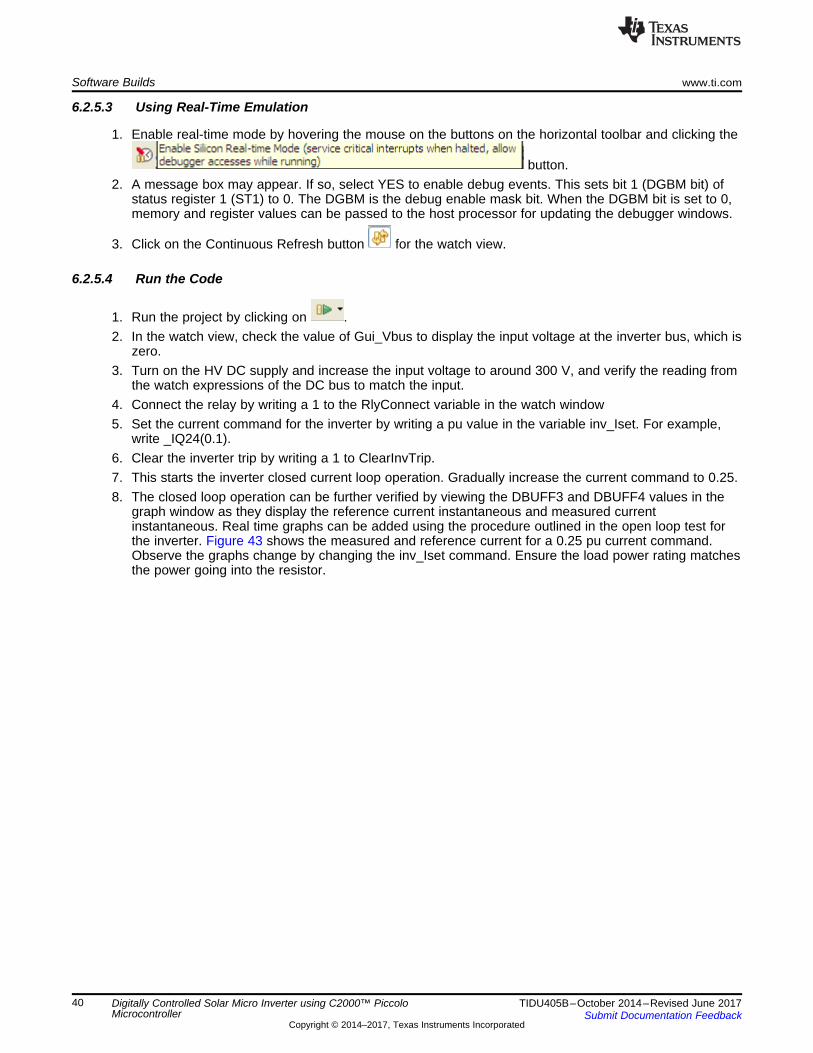
Software Builds www.ti.com
40 TIDU405B–October 2014–Revised June 2017Submit Documentation Feedback
Copyright © 2014–2017, Texas Instruments Incorporated
Digitally Controlled Solar Micro Inverter using C2000™ PiccoloMicrocontroller
6.2.5.3 Using Real-Time Emulation
1. Enable real-time mode by hovering the mouse on the buttons on the horizontal toolbar and clicking the
button.2. A message box may appear. If so, select YES to enable debug events. This sets bit 1 (DGBM bit) of
status register 1 (ST1) to 0. The DGBM is the debug enable mask bit. When the DGBM bit is set to 0,memory and register values can be passed to the host processor for updating the debugger windows.
3. Click on the Continuous Refresh button for the watch view.
6.2.5.4 Run the Code
1. Run the project by clicking on .2. In the watch view, check the value of Gui_Vbus to display the input voltage at the inverter bus, which is
zero.3. Turn on the HV DC supply and increase the input voltage to around 300 V, and verify the reading from
the watch expressions of the DC bus to match the input.4. Connect the relay by writing a 1 to the RlyConnect variable in the watch window5. Set the current command for the inverter by writing a pu value in the variable inv_Iset. For example,
write _IQ24(0.1).6. Clear the inverter trip by writing a 1 to ClearInvTrip.7. This starts the inverter closed current loop operation. Gradually increase the current command to 0.25.8. The closed loop operation can be further verified by viewing the DBUFF3 and DBUFF4 values in the
graph window as they display the reference current instantaneous and measured currentinstantaneous. Real time graphs can be added using the procedure outlined in the open loop test forthe inverter. Figure 43 shows the measured and reference current for a 0.25 pu current command.Observe the graphs change by changing the inv_Iset command. Ensure the load power rating matchesthe power going into the resistor.
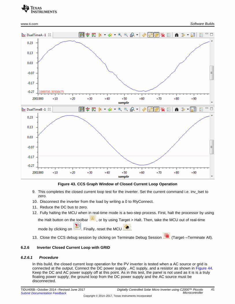
www.ti.com Software Builds
41TIDU405B–October 2014–Revised June 2017Submit Documentation Feedback
Copyright © 2014–2017, Texas Instruments Incorporated
Digitally Controlled Solar Micro Inverter using C2000™ PiccoloMicrocontroller
Figure 43. CCS Graph Window of Closed Current Loop Operation
9. This completes the closed current loop test for the inverter. Set the current command i.e. inv_Iset tozero.
10. Disconnect the inverter from the load by writing a 0 to RlyConnect.11. Reduce the DC bus to zero.12. Fully halting the MCU when in real-time mode is a two-step process. First, halt the processor by using
the Halt button on the toolbar , or by using Target > Halt. Then, take the MCU out of real-time
mode by clicking on . Finally, reset the MCU .
13. Close the CCS debug session by clicking on Terminate Debug Session (Target→Terminate All).
6.2.6 Inverter Closed Current Loop with GRID
6.2.6.1 ProcedureIn this build, the closed current loop operation for the PV inverter is tested when a AC source or grid isconnected at the output. Connect the DC power supply , AC supply, and a resistor as shown in Figure 44.Keep the DC and AC power supply off at this point. As in this test, the panel is not used as it is is a trulyfloating power supply; the ground loop from the DC power supply and the AC source must bedisconnected.
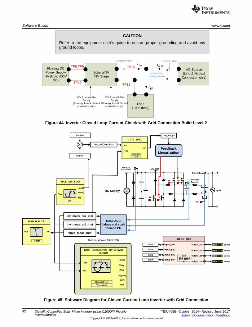
Inverter DC Bus Feedback DC bus
1A
Grid Voltage
Converter Current
1B
2A 2B
R1
Inv_Iset
Read ADC Values and scale
them to PU
inv_meas_cur_inst
inv_meas_vol_inst
vbus_meas_inst
.cos(�).Vin
SPLL_1ph_SOGI
wn
.(�)
.sin(�)
InvSine
DLOG_4CH
input_ptr1 output_ptr1
sizetrig_valuepre_scal
ar
DBUFF1
output_ptr2 DBUFF2
output_ptr3 DBUFF3
output_ptr4 DBUFF4
input_ptr2
input_ptr3
input_ptr4
dval1
dval2
dval3
dval4
.In
NOTCH_FLTR
.Out
Coeff
.Vrms.Vin
Solar_SineAnalyzer_diff_wPower(struct)
SampleFreqThreshold
.Vavg
.Sigfreq
.ZCD
T=1/f
.Iin .Pwr
.Irms
Run in slower 1Khz ISR
DC Supply I
Feedback Linearization
duty_inv_pu
.Out.Ref
.Fdbk
CNTL_3P3Z
DBUFFCoef
inv_ref_cur_inst
Vgrid
AC Source(Line & Neutral
Connection only)
Solar uINVINV Stage
Load(100 Ohms)
Rli
invigridi
Current ProbeCurrent Probe
Floating DC Power Supply HV (Upto 400V
DC)
TP8,TP9
TP10
TP15
TP16
Differential Voltage Probe
12V External Bias Supply
(Floating, Line & Neutral connection only)
15V External Bias Supply
(Floating, Line & Neutral connection only)
Software Builds www.ti.com
42 TIDU405B–October 2014–Revised June 2017Submit Documentation Feedback
Copyright © 2014–2017, Texas Instruments Incorporated
Digitally Controlled Solar Micro Inverter using C2000™ PiccoloMicrocontroller
CAUTIONRefer to the equipment user’s guide to ensure proper grounding and avoid anyground loops.
Figure 44. Inverter Closed Loop Current Check with Grid Connection Build Level 2
Figure 45. Software Diagram for Closed Current Loop Inverter with Grid Connection
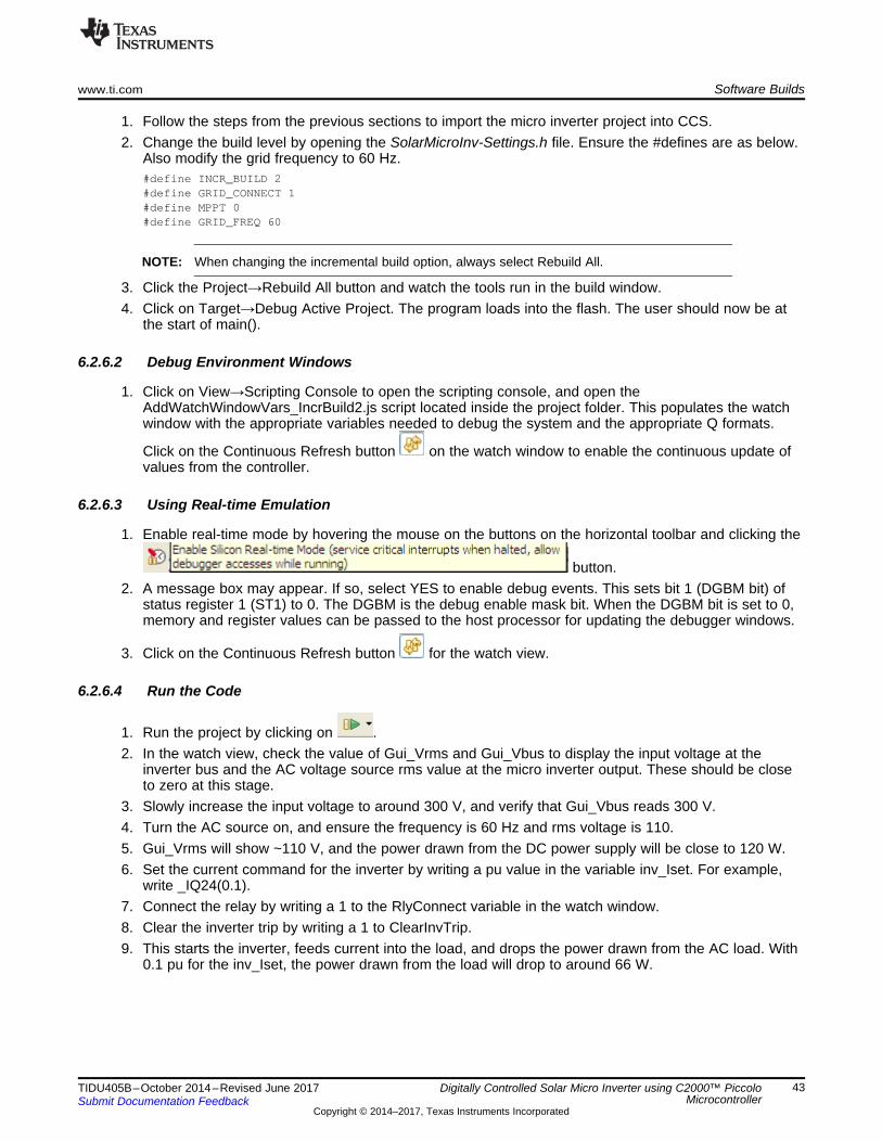
www.ti.com Software Builds
43TIDU405B–October 2014–Revised June 2017Submit Documentation Feedback
Copyright © 2014–2017, Texas Instruments Incorporated
Digitally Controlled Solar Micro Inverter using C2000™ PiccoloMicrocontroller
1. Follow the steps from the previous sections to import the micro inverter project into CCS.2. Change the build level by opening the SolarMicroInv-Settings.h file. Ensure the #defines are as below.
Also modify the grid frequency to 60 Hz.#define INCR_BUILD 2#define GRID_CONNECT 1#define MPPT 0#define GRID_FREQ 60
NOTE: When changing the incremental build option, always select Rebuild All.
3. Click the Project→Rebuild All button and watch the tools run in the build window.4. Click on Target→Debug Active Project. The program loads into the flash. The user should now be at
the start of main().
6.2.6.2 Debug Environment Windows
1. Click on View→Scripting Console to open the scripting console, and open theAddWatchWindowVars_IncrBuild2.js script located inside the project folder. This populates the watchwindow with the appropriate variables needed to debug the system and the appropriate Q formats.
Click on the Continuous Refresh button on the watch window to enable the continuous update ofvalues from the controller.
6.2.6.3 Using Real-time Emulation
1. Enable real-time mode by hovering the mouse on the buttons on the horizontal toolbar and clicking the
button.2. A message box may appear. If so, select YES to enable debug events. This sets bit 1 (DGBM bit) of
status register 1 (ST1) to 0. The DGBM is the debug enable mask bit. When the DGBM bit is set to 0,memory and register values can be passed to the host processor for updating the debugger windows.
3. Click on the Continuous Refresh button for the watch view.
6.2.6.4 Run the Code
1. Run the project by clicking on .2. In the watch view, check the value of Gui_Vrms and Gui_Vbus to display the input voltage at the
inverter bus and the AC voltage source rms value at the micro inverter output. These should be closeto zero at this stage.
3. Slowly increase the input voltage to around 300 V, and verify that Gui_Vbus reads 300 V.4. Turn the AC source on, and ensure the frequency is 60 Hz and rms voltage is 110.5. Gui_Vrms will show ~110 V, and the power drawn from the DC power supply will be close to 120 W.6. Set the current command for the inverter by writing a pu value in the variable inv_Iset. For example,
write _IQ24(0.1).7. Connect the relay by writing a 1 to the RlyConnect variable in the watch window.8. Clear the inverter trip by writing a 1 to ClearInvTrip.9. This starts the inverter, feeds current into the load, and drops the power drawn from the AC load. With
0.1 pu for the inv_Iset, the power drawn from the load will drop to around 66 W.
Software Builds www.ti.com
44 TIDU405B–October 2014–Revised June 2017Submit Documentation Feedback
Copyright © 2014–2017, Texas Instruments Incorporated
Digitally Controlled Solar Micro Inverter using C2000™ PiccoloMicrocontroller
CAUTIONThe AC source cannot take reverse power flow, therefore do not increase theinv_Iset such that the micro inverter board feeds power into the AC source, asthis can damage the AC power supply. The maximum value for the setupdescribed above is around 0.2 pu.
10. The closed loop operation can further be verified by viewing the DBUFF3 and DBUFF4 in the graphwindow. DBUFF3 and DBUFF4 display the reference current instantaneous and measured currentinstantaneous. Real time graphs can be added using the procedure outlined in Section 6.1.2.
11. The inv_Iset, maximum 0.2 pu for the setup described above, can be changed and the performanceof the grid-connected closed current loop inverter verified.
12. This completes the closed current loop with grid test for the inverter. To stop the operation, putRlyConnect to 0.
13. Set the current command, such as inv_Iset, to zero.14. Reduce the AC voltage to zero.15. Reduce the DC bus to zero.16. Fully halting the MCU when in real-time mode is a two-step process. First, halt the processor by using
the Halt button on the toolbar, or by using Target > Halt. Then, take the MCU out of real-time
mode by clicking on . Finally reset the MCU by clicking on .
17. Close the CCS debug session by clicking on Terminate Debug Session (Target→Terminate All).
6.3 Build = 3
6.3.1 ObjectiveThe objective of this build is to run the full PV inverter system with closed current loop and DC bus voltagecontrol. To connect the PV inverter to grid, a precise state machine must be followed to start the flybackstage, connect the relay, and start the inverter. The software must detect the grid frequency and adjust theDC bus voltage regulation parameters. Figure 46 illustrates the state machine used for the PV invertersystem. Two build options are provided; one with MPPT and one without. This enables the user to tunethe DC bus voltage controller without MPPT, and enables the use of a DC power supply at the inputinstead of a PV panel.
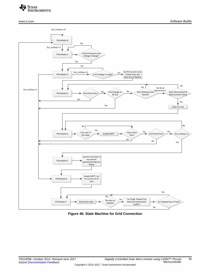
Gui_InvStart==0
Gui_InvStart==1
Is Grid Frequency and
Voltage in Range?
PVInvState=0
PVInvState=1
No
PVInvState=2
Yes
Gui_InvStop==1
Is PV Voltage in range?Gui_InvStop==0
No
PVInvState=3
Yes
Grid Check Pass?Yes
No
Set PV Current to be
a fixed value and
clear trip on flyback
OverVoltage on
DC Bus
Yes
No Vbus>RelayConnect
BusVolt
No
Vbus>VbusInvStart &
Relay Connect Check
Clear Inv Trip
Yes & set
RlyConnect=1
Yes
No
PVInvState=41 sec over in
this stateEnable MPPT
No
YesVbus Check
Pass?
No
Grid Check Pass?Yes
No
Gui_InvStop==1
No
PVInvState=5
Yes
Yes
Log the Fault State if
any and set
appropriate flags for
debug
PVInvState=6
Disable MPPT, Set
PV current ref to
zero
PVInvState=7No duty on
Flyback?Disconnect relay
No
Inv Trip& Flyback Trip
Reset all compensator
buffers
Inv Stopped due to Fault?
Yes
Yes
No
www.ti.com Software Builds
45TIDU405B–October 2014–Revised June 2017Submit Documentation Feedback
Copyright © 2014–2017, Texas Instruments Incorporated
Digitally Controlled Solar Micro Inverter using C2000™ PiccoloMicrocontroller
Figure 46. State Machine for Grid Connection
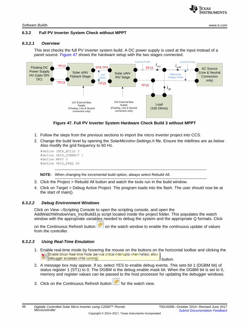
Solar uINVFlyback Stage
AC Source(Line & Neutral
Connection only)
Solar uINVINV Stage
Load(100 Ohms)
Rli
invigridi
Current ProbeCurrent Probe
TP8,TP9
TP10
TP15
TP16
Differential Voltage Probe
Floating DC Power Supply HV (Upto 50V
DC)
TP12
TP13
Volt Meter
12V External Bias Supply
(Floating, Line & Neutral connection only)
15V External Bias Supply
(Floating, Line & Neutral connection only)
Software Builds www.ti.com
46 TIDU405B–October 2014–Revised June 2017Submit Documentation Feedback
Copyright © 2014–2017, Texas Instruments Incorporated
Digitally Controlled Solar Micro Inverter using C2000™ PiccoloMicrocontroller
6.3.2 Full PV Inverter System Check without MPPT
6.3.2.1 OverviewThis test checks the full PV inverter system build. A DC power supply is used at the input instead of apanel source. Figure 47 shows the hardware setup with the two stages connected.
Figure 47. Full PV Inverter System Hardware Check Build 3 without MPPT
1. Follow the steps from the previous sections to import the micro inverter project into CCS.2. Change the build level by opening the SolarMicroInv-Settings.h file. Ensure the #defines are as below .
Also modify the grid frequency to 60 Hz.#define INCR_BUILD 3#define GRID_CONNECT 1#define MPPT 0#define GRID_FREQ 60
NOTE: When changing the incremental build option, always select Rebuild All.
3. Click the Project > Rebuild All button and watch the tools run in the build window.4. Click on Target > Debug Active Project. The program loads into the flash. The user should now be at
the start of main().
6.3.2.2 Debug Environment WindowsClick on View→Scripting Console to open the scripting console, and open theAddWatchWindowVars_IncrBuild3.js script located inside the project folder. This populates the watchwindow with the appropriate variables needed to debug the system and the appropriate Q formats. Click
on the Continuous Refresh button on the watch window to enable the continuous update of valuesfrom the controller.
6.3.2.3 Using Real-Time Emulation
1. Enable real-time mode by hovering the mouse on the buttons on the horizontal toolbar and clicking the
button.2. A message box may appear. If so, select YES to enable debug events. This sets bit 1 (DGBM bit) of
status register 1 (ST1) to 0. The DGBM is the debug enable mask bit. When the DGBM bit is set to 0,memory and register values can be passed to the host processor for updating the debugger windows.
3. Click on the Continuous Refresh button for the watch view.
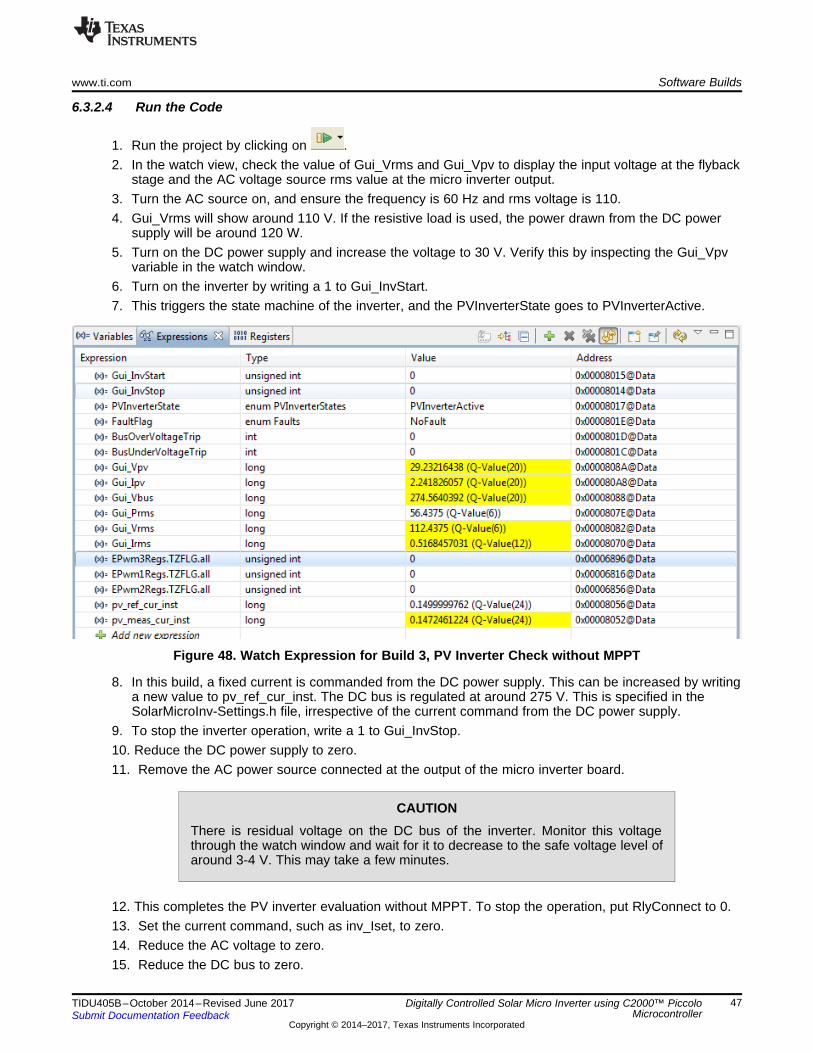
www.ti.com Software Builds
47TIDU405B–October 2014–Revised June 2017Submit Documentation Feedback
Copyright © 2014–2017, Texas Instruments Incorporated
Digitally Controlled Solar Micro Inverter using C2000™ PiccoloMicrocontroller
6.3.2.4 Run the Code
1. Run the project by clicking on .2. In the watch view, check the value of Gui_Vrms and Gui_Vpv to display the input voltage at the flyback
stage and the AC voltage source rms value at the micro inverter output.3. Turn the AC source on, and ensure the frequency is 60 Hz and rms voltage is 110.4. Gui_Vrms will show around 110 V. If the resistive load is used, the power drawn from the DC power
supply will be around 120 W.5. Turn on the DC power supply and increase the voltage to 30 V. Verify this by inspecting the Gui_Vpv
variable in the watch window.6. Turn on the inverter by writing a 1 to Gui_InvStart.7. This triggers the state machine of the inverter, and the PVInverterState goes to PVInverterActive.
Figure 48. Watch Expression for Build 3, PV Inverter Check without MPPT
8. In this build, a fixed current is commanded from the DC power supply. This can be increased by writinga new value to pv_ref_cur_inst. The DC bus is regulated at around 275 V. This is specified in theSolarMicroInv-Settings.h file, irrespective of the current command from the DC power supply.
9. To stop the inverter operation, write a 1 to Gui_InvStop.10. Reduce the DC power supply to zero.11. Remove the AC power source connected at the output of the micro inverter board.
CAUTIONThere is residual voltage on the DC bus of the inverter. Monitor this voltagethrough the watch window and wait for it to decrease to the safe voltage level ofaround 3-4 V. This may take a few minutes.
12. This completes the PV inverter evaluation without MPPT. To stop the operation, put RlyConnect to 0.13. Set the current command, such as inv_Iset, to zero.14. Reduce the AC voltage to zero.15. Reduce the DC bus to zero.
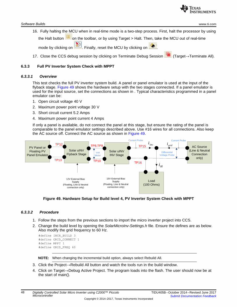
Solar uINVFlyback Stage
AC Source(Line & Neutral
Connection only)
Solar uINVINV Stage
Load(100 Ohms)
Rli
invigridi
Current ProbeCurrent Probe
TP8,TP9
TP10
TP15
TP16
Differential Voltage Probe
PV Panel or Floating PV
Panel Emulator
TP12
TP13
Volt Meter
12V External Bias Supply
(Floating, Line & Neutral connection only)
15V External Bias Supply
(Floating, Line & Neutral connection only)
Software Builds www.ti.com
48 TIDU405B–October 2014–Revised June 2017Submit Documentation Feedback
Copyright © 2014–2017, Texas Instruments Incorporated
Digitally Controlled Solar Micro Inverter using C2000™ PiccoloMicrocontroller
16. Fully halting the MCU when in real-time mode is a two-step process. First, halt the processor by using
the Halt button on the toolbar, or by using Target > Halt. Then, take the MCU out of real-time
mode by clicking on . Finally, reset the MCU by clicking on .
17. Close the CCS debug session by clicking on Terminate Debug Session (Target→Terminate All).
6.3.3 Full PV Inverter System Check with MPPT
6.3.3.1 OverviewThis test checks the full PV inverter system build. A panel or panel emulator is used at the input of theflyback stage. Figure 49 shows the hardware setup with the two stages connected. If a panel emulator isused for the input source, set the connections as shown in . Typical characteristics programmed in a panelemulator can be:1. Open circuit voltage 40 V2. Maximum power point voltage 30 V3. Short circuit current 5.2 Amps4. Maximum power point current 4 Amps
If only a panel is available, do not connect the panel at this stage, but ensure the rating of the panel iscomparable to the panel emulator settings described above. Use #16 wires for all connections. Also keepthe AC source off. Connect the AC source as shown in Figure 49.
Figure 49. Hardware Setup for Build level 4, PV Inverter System Check with MPPT
6.3.3.2 Procedure
1. Follow the steps from the previous sections to import the micro inverter project into CCS.2. Change the build level by opening the SolarMicroInv-Settings.h file. Ensure the defines are as below.
Also modify the grid frequency to 60 Hz.#define INCR_BUILD 3#define GRID_CONNECT 1#define MPPT 1#define GRID_FREQ 60
NOTE: When changing the incremental build option, always select Rebuild All.
3. Click the Project→Rebuild All button and watch the tools run in the build window.4. Click on Target→Debug Active Project. The program loads into the flash. The user should now be at
the start of main().
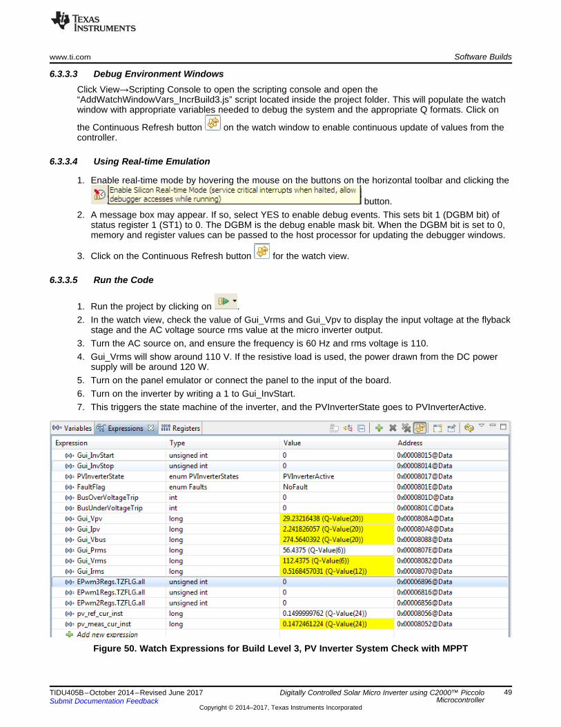
www.ti.com Software Builds
49TIDU405B–October 2014–Revised June 2017Submit Documentation Feedback
Copyright © 2014–2017, Texas Instruments Incorporated
Digitally Controlled Solar Micro Inverter using C2000™ PiccoloMicrocontroller
6.3.3.3 Debug Environment WindowsClick View→Scripting Console to open the scripting console and open the“AddWatchWindowVars_IncrBuild3.js” script located inside the project folder. This will populate the watchwindow with appropriate variables needed to debug the system and the appropriate Q formats. Click on
the Continuous Refresh button on the watch window to enable continuous update of values from thecontroller.
6.3.3.4 Using Real-time Emulation
1. Enable real-time mode by hovering the mouse on the buttons on the horizontal toolbar and clicking the
button.2. A message box may appear. If so, select YES to enable debug events. This sets bit 1 (DGBM bit) of
status register 1 (ST1) to 0. The DGBM is the debug enable mask bit. When the DGBM bit is set to 0,memory and register values can be passed to the host processor for updating the debugger windows.
3. Click on the Continuous Refresh button for the watch view.
6.3.3.5 Run the Code
1. Run the project by clicking on .2. In the watch view, check the value of Gui_Vrms and Gui_Vpv to display the input voltage at the flyback
stage and the AC voltage source rms value at the micro inverter output.3. Turn the AC source on, and ensure the frequency is 60 Hz and rms voltage is 110.4. Gui_Vrms will show around 110 V. If the resistive load is used, the power drawn from the DC power
supply will be around 120 W.5. Turn on the panel emulator or connect the panel to the input of the board.6. Turn on the inverter by writing a 1 to Gui_InvStart.7. This triggers the state machine of the inverter, and the PVInverterState goes to PVInverterActive.
Figure 50. Watch Expressions for Build Level 3, PV Inverter System Check with MPPT
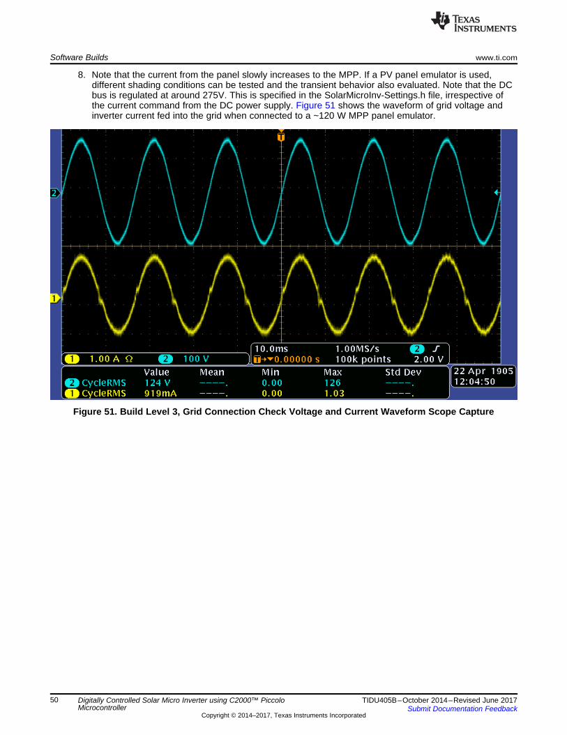
Software Builds www.ti.com
50 TIDU405B–October 2014–Revised June 2017Submit Documentation Feedback
Copyright © 2014–2017, Texas Instruments Incorporated
Digitally Controlled Solar Micro Inverter using C2000™ PiccoloMicrocontroller
8. Note that the current from the panel slowly increases to the MPP. If a PV panel emulator is used,different shading conditions can be tested and the transient behavior also evaluated. Note that the DCbus is regulated at around 275V. This is specified in the SolarMicroInv-Settings.h file, irrespective ofthe current command from the DC power supply. Figure 51 shows the waveform of grid voltage andinverter current fed into the grid when connected to a ~120 W MPP panel emulator.
Figure 51. Build Level 3, Grid Connection Check Voltage and Current Waveform Scope Capture
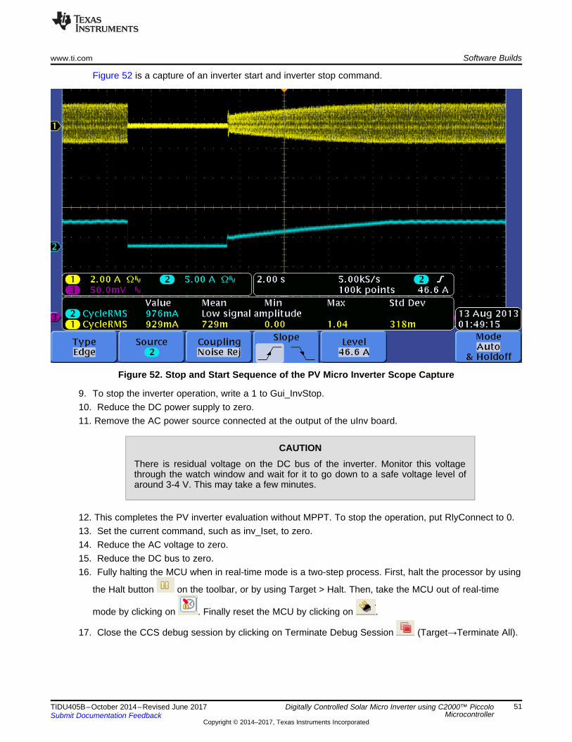
www.ti.com Software Builds
51TIDU405B–October 2014–Revised June 2017Submit Documentation Feedback
Copyright © 2014–2017, Texas Instruments Incorporated
Digitally Controlled Solar Micro Inverter using C2000™ PiccoloMicrocontroller
Figure 52 is a capture of an inverter start and inverter stop command.
Figure 52. Stop and Start Sequence of the PV Micro Inverter Scope Capture
9. To stop the inverter operation, write a 1 to Gui_InvStop.10. Reduce the DC power supply to zero.11. Remove the AC power source connected at the output of the uInv board.
CAUTIONThere is residual voltage on the DC bus of the inverter. Monitor this voltagethrough the watch window and wait for it to go down to a safe voltage level ofaround 3-4 V. This may take a few minutes.
12. This completes the PV inverter evaluation without MPPT. To stop the operation, put RlyConnect to 0.13. Set the current command, such as inv_Iset, to zero.14. Reduce the AC voltage to zero.15. Reduce the DC bus to zero.16. Fully halting the MCU when in real-time mode is a two-step process. First, halt the processor by using
the Halt button on the toolbar, or by using Target > Halt. Then, take the MCU out of real-time
mode by clicking on . Finally reset the MCU by clicking on .
17. Close the CCS debug session by clicking on Terminate Debug Session (Target→Terminate All).
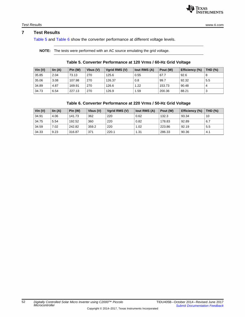
Test Results www.ti.com
52 TIDU405B–October 2014–Revised June 2017Submit Documentation Feedback
Copyright © 2014–2017, Texas Instruments Incorporated
Digitally Controlled Solar Micro Inverter using C2000™ PiccoloMicrocontroller
7 Test ResultsTable 5 and Table 6 show the converter performance at different voltage levels.
NOTE: The tests were performed with an AC source emulating the grid voltage.
Table 5. Converter Performance at 120 Vrms / 60-Hz Grid Voltage
Vin (V) Iin (A) Pin (W) Vbus (V) Vgrid RMS (V) Iout RMS (A) Pout (W) Efficiency (%) THD (%)35.85 2.04 73.13 270 125.6 0.55 67.7 92.6 835.06 3.08 107.98 270 126.37 0.8 99.7 92.32 5.534.89 4.87 169.91 270 126.6 1.22 153.73 90.48 434.73 6.54 227.13 270 126.9 1.59 200.36 88.21 3
Table 6. Converter Performance at 220 Vrms / 50-Hz Grid Voltage
Vin (V) Iin (A) Pin (W) Vbus (V) Vgrid RMS (V) Iout RMS (A) Pout (W) Efficiency (%) THD (%)34.91 4.06 141.73 362 220 0.62 132.3 93.34 1034.75 5.54 192.52 360 220 0.82 178.83 92.89 6.734.59 7.02 242.82 359.2 220 1.02 223.86 92.19 5.534.33 9.23 316.87 371 220.1 1.31 286.33 90.36 4.1
www.ti.com References
53TIDU405B–October 2014–Revised June 2017Submit Documentation Feedback
Copyright © 2014–2017, Texas Instruments Incorporated
Digitally Controlled Solar Micro Inverter using C2000™ PiccoloMicrocontroller
8 ReferencesFor more information, refer to the following guides:1. Solar Micro Inverter-GUI-QSG – A quick-start guide for a quick demo of the Solar Micro Inverter EVM
using a GUIinterface. ..\controlSUITE\development_kits\TMDSSOLARUINVKIT_version\~Docs\QSG_Solar_Micro_Inve rter_GUI_Rev1.0.pdf
2. Solar Micro Inverter_Rel-1.0-HWdevPkg – A folder containing various files related to the Piccolo-Bcontroller card schematics and the Micro Inverterschematic. ..\controlSUITE\development_kits\TMDSSOLARUINVKIT_version\Solar_Micro-Inverter_HWDevPkg
3. F28xxx User’s Guides – http://www.ti.com/f28xuserguides4. Software Phased-Locked Loop Design Using C2000™ Microcontrollers for Single Phase Grid
Connected Inverter (SPRABT3), July 2013.
About the Authors www.ti.com
54 TIDU405B–October 2014–Revised June 2017Submit Documentation Feedback
Copyright © 2014–2017, Texas Instruments Incorporated
Digitally Controlled Solar Micro Inverter using C2000™ PiccoloMicrocontroller
9 About the AuthorsMANISH BHARDWAJ is a Systems Application Engineer at Texas Instruments, responsible fordeveloping system solutions for C2000 microcontrollers. Before joining TI in 2009, Manish received hisMasters of Science in Electrical and Computer Engineering from Georgia Institute of Technology, Atlantaand Bachelor of Engineering from Netaji Subhash Institute of Technology, University of Delhi, India. Hecan be reached at [email protected].
SHAMIM CHOUDHURY has been with Texas Instruments Inc. since December 1997, where he currentlyleads the C2000 Digital Power Application team. As a member of the C2000 System Applications team formany years, his areas of interest have been on digital control of power converters, switching powersupplies, Power Factor Correction, UPS and Solar Inverters. Prior to joining TI, he spent two years atAlcatel, and three years at International Game Technology, as a Design Engineer working on switch modepower supplies. He received his M.S. degree in Electrical Engineering from Texas A&M University inCollege Station, TX, in December 1991. He can be reached at [email protected].
www.ti.com Revision History
55TIDU405B–October 2014–Revised June 2017Submit Documentation Feedback
Copyright © 2014–2017, Texas Instruments Incorporated
Revision History
Revision HistoryNOTE: Page numbers for previous revisions may differ from page numbers in the current version.
Changes from March 1, 2016 to June 30, 2017 (from A Revision (February 2016) to B Revision) ............................. Page
• Added Test Resutls section. ........................................................................................................... 52
IMPORTANT NOTICE FOR TI DESIGN INFORMATION AND RESOURCES
Texas Instruments Incorporated (‘TI”) technical, application or other design advice, services or information, including, but not limited to,reference designs and materials relating to evaluation modules, (collectively, “TI Resources”) are intended to assist designers who aredeveloping applications that incorporate TI products; by downloading, accessing or using any particular TI Resource in any way, you(individually or, if you are acting on behalf of a company, your company) agree to use it solely for this purpose and subject to the terms ofthis Notice.TI’s provision of TI Resources does not expand or otherwise alter TI’s applicable published warranties or warranty disclaimers for TIproducts, and no additional obligations or liabilities arise from TI providing such TI Resources. TI reserves the right to make corrections,enhancements, improvements and other changes to its TI Resources.You understand and agree that you remain responsible for using your independent analysis, evaluation and judgment in designing yourapplications and that you have full and exclusive responsibility to assure the safety of your applications and compliance of your applications(and of all TI products used in or for your applications) with all applicable regulations, laws and other applicable requirements. Yourepresent that, with respect to your applications, you have all the necessary expertise to create and implement safeguards that (1)anticipate dangerous consequences of failures, (2) monitor failures and their consequences, and (3) lessen the likelihood of failures thatmight cause harm and take appropriate actions. You agree that prior to using or distributing any applications that include TI products, youwill thoroughly test such applications and the functionality of such TI products as used in such applications. TI has not conducted anytesting other than that specifically described in the published documentation for a particular TI Resource.You are authorized to use, copy and modify any individual TI Resource only in connection with the development of applications that includethe TI product(s) identified in such TI Resource. NO OTHER LICENSE, EXPRESS OR IMPLIED, BY ESTOPPEL OR OTHERWISE TOANY OTHER TI INTELLECTUAL PROPERTY RIGHT, AND NO LICENSE TO ANY TECHNOLOGY OR INTELLECTUAL PROPERTYRIGHT OF TI OR ANY THIRD PARTY IS GRANTED HEREIN, including but not limited to any patent right, copyright, mask work right, orother intellectual property right relating to any combination, machine, or process in which TI products or services are used. Informationregarding or referencing third-party products or services does not constitute a license to use such products or services, or a warranty orendorsement thereof. Use of TI Resources may require a license from a third party under the patents or other intellectual property of thethird party, or a license from TI under the patents or other intellectual property of TI.TI RESOURCES ARE PROVIDED “AS IS” AND WITH ALL FAULTS. TI DISCLAIMS ALL OTHER WARRANTIES ORREPRESENTATIONS, EXPRESS OR IMPLIED, REGARDING TI RESOURCES OR USE THEREOF, INCLUDING BUT NOT LIMITED TOACCURACY OR COMPLETENESS, TITLE, ANY EPIDEMIC FAILURE WARRANTY AND ANY IMPLIED WARRANTIES OFMERCHANTABILITY, FITNESS FOR A PARTICULAR PURPOSE, AND NON-INFRINGEMENT OF ANY THIRD PARTY INTELLECTUALPROPERTY RIGHTS.TI SHALL NOT BE LIABLE FOR AND SHALL NOT DEFEND OR INDEMNIFY YOU AGAINST ANY CLAIM, INCLUDING BUT NOTLIMITED TO ANY INFRINGEMENT CLAIM THAT RELATES TO OR IS BASED ON ANY COMBINATION OF PRODUCTS EVEN IFDESCRIBED IN TI RESOURCES OR OTHERWISE. IN NO EVENT SHALL TI BE LIABLE FOR ANY ACTUAL, DIRECT, SPECIAL,COLLATERAL, INDIRECT, PUNITIVE, INCIDENTAL, CONSEQUENTIAL OR EXEMPLARY DAMAGES IN CONNECTION WITH ORARISING OUT OF TI RESOURCES OR USE THEREOF, AND REGARDLESS OF WHETHER TI HAS BEEN ADVISED OF THEPOSSIBILITY OF SUCH DAMAGES.You agree to fully indemnify TI and its representatives against any damages, costs, losses, and/or liabilities arising out of your non-compliance with the terms and provisions of this Notice.This Notice applies to TI Resources. Additional terms apply to the use and purchase of certain types of materials, TI products and services.These include; without limitation, TI’s standard terms for semiconductor products http://www.ti.com/sc/docs/stdterms.htm), evaluationmodules, and samples (http://www.ti.com/sc/docs/sampterms.htm).
Mailing Address: Texas Instruments, Post Office Box 655303, Dallas, Texas 75265Copyright © 2017, Texas Instruments Incorporated