Embed Size (px)
Citation preview
Digital Temperature Controller E5CN
Compact and Intelligent TemperatureController
Auto-tuning and self-tuning available.Can auto-tune even during execution ofself-tuning
Heating or heating/cooling control isavailable
Event input allows multiple SP selectionand run/stop function
Water-resistant construction: NEMA4(equivalent to IP66)
Various temperature inputs:thermocouple, platinum resistancethermometer, non-contact temperaturesensor, and analog inputs
Conforms to UL, CSA, IEC, and CE
Ordering Information E5CN STANDARD MODELS
Description Part number
Size Power supplyvoltage
No. ofalarmpoints
Output Thermocouple model Platinum resistancethermometer model
1/16 DIN48(W) 48(H)
100 to 240 VAC --- Relay E5CN-RMTC-500 AC100-240 E5CN-RMP-500 AC100-24048(W) x 48(H) x78(D) mm
Voltage output(for driving SSR)
E5CN-QMTC-500 AC100-240 E5CN-QMP-500 AC100-240
2 Relay E5CN-R2MTC-500 AC100-240 E5CN-R2MP-500 AC100-240
Voltage output(for driving SSR)
E5CN-Q2MTC-500 AC100-240 E5CN-Q2MP-500 AC100-240
24 VAC/VDC --- Relay E5CN-RMTC-500 AC/DC24 E5CN-RMP-500 AC/DC24
Voltage output(for driving SSR)
E5CN-QMTC-500 AC/DC24 E5CN-QMP-500 AC/DC24
2 Relay E5CN-R2MTC-500 AC/DC24 E5CN-R2MP-500 AC/DC24
Voltage output(for driving SSR)
E5CN-Q2MTC-500 AC/DC24 E5CN-Q2MP-500 AC/DC24
Note: 1. The suffix “500” is added to the part number of each Controller provided with a E53-COV10 Terminal Cover.2. The heating and cooling function is available for models with two alarm points.
E5CNE5CN
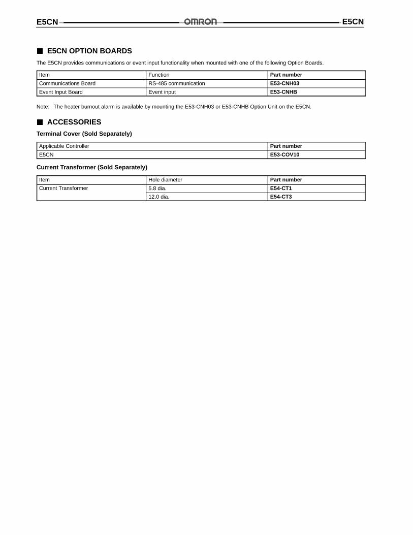
E5CN OPTION BOARDS
The E5CN provides communications or event input functionality when mounted with one of the following Option Boards.
Item Function Part number
Communications Board RS-485 communication E53-CNH03
Event Input Board Event input E53-CNHB
Note: The heater burnout alarm is available by mounting the E53-CNH03 or E53-CNHB Option Unit on the E5CN.
ACCESSORIES
Terminal Cover (Sold Separately)
Applicable Controller Part number
E5CN E53-COV10
Current Transformer (Sold Separately)
Item Hole diameter Part number
Current Transformer 5.8 dia. E54-CT1
12.0 dia. E54-CT3
E5CN E5CN
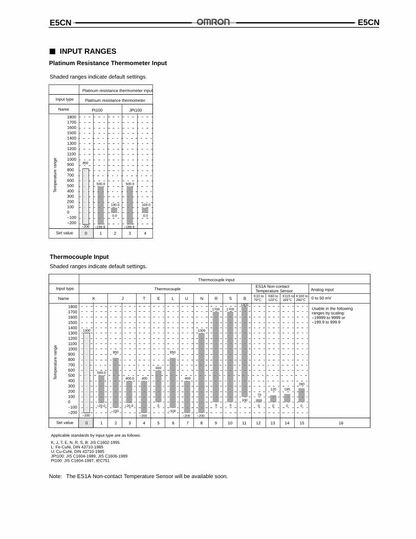
INPUT RANGES
Platinum Resistance Thermometer InputTe
mpe
ratu
rera
nge
1800170016001500140013001200110010009008007006005004003002001000--100--200
Pt100 JPt100
Input type
Platinum resistance thermometer input
Platinum resistance thermometer
Name
850
Set value 1 2 3 4
--200
500.0
--199.9
100.0
0.0
500.0
--199.9
100.0
0.0
0
Shaded ranges indicate default settings.
Thermocouple
Thermocouple input
ES1A Non-contactTemperature Sensor Analog input
Usable in the followingranges by scaling:--19999 to 9999 or--199.9 to 999.9
0 to 50 mV
Tem
pera
ture
rang
e
1800170016001500140013001200110010009008007006005004003002001000--100--200
Input type
Name K J T E L U N R S BK10 to70°C
K60 to120°C
K115 to165°C
K160 to260°C
Set value 1 2 3 4 5 6 7 8 9 10 11 12 13 14 15 16
--200
500.0
--20.0
1300
850
--100
400.0
--20.0
400
--200
600
0
850
--100
400
--200
1300
--200
1700
0
1700
0
1800
100
70
0
120
0
165
0
260
0
0
Thermocouple Input
Shaded ranges indicate default settings.
Applicable standards by input type are as follows:
K, J, T, E, N, R, S, B: JIS C1602-1995L: Fe-CuNi, DIN 43710-1985U: Cu-CuNi, DIN 43710-1985JPt100: JIS C1604-1989, JIS C1606-1989Pt100: JIS C1604-1997, IEC751
Note: The ES1A Non-contact Temperature Sensor will be available soon.
E5CNE5CN
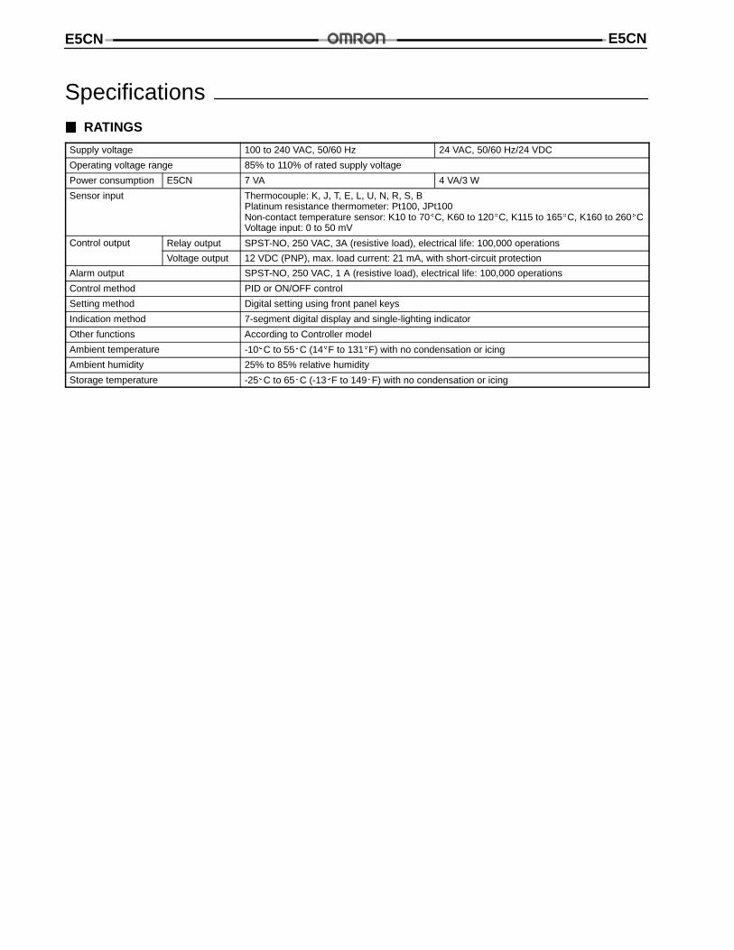
Specifications RATINGS
Supply voltage 100 to 240 VAC, 50/60 Hz 24 VAC, 50/60 Hz/24 VDC
Operating voltage range 85% to 110% of rated supply voltage
Power consumption E5CN 7 VA 4 VA/3 W
Sensor input Thermocouple: K, J, T, E, L, U, N, R, S, BPlatinum resistance thermometer: Pt100, JPt100Non-contact temperature sensor: K10 to 70C, K60 to 120C, K115 to 165C, K160 to 260CVoltage input: 0 to 50 mV
Control output Relay output SPST-NO, 250 VAC, 3A (resistive load), electrical life: 100,000 operations
Voltage output 12 VDC (PNP), max. load current: 21 mA, with short-circuit protection
Alarm output SPST-NO, 250 VAC, 1 A (resistive load), electrical life: 100,000 operations
Control method PID or ON/OFF control
Setting method Digital setting using front panel keys
Indication method 7-segment digital display and single-lighting indicator
Other functions According to Controller model
Ambient temperature -10C to 55C (14F to 131F) with no condensation or icing
Ambient humidity 25% to 85% relative humidity
Storage temperature -25C to 65C (-13F to 149F) with no condensation or icing
E5CN E5CN
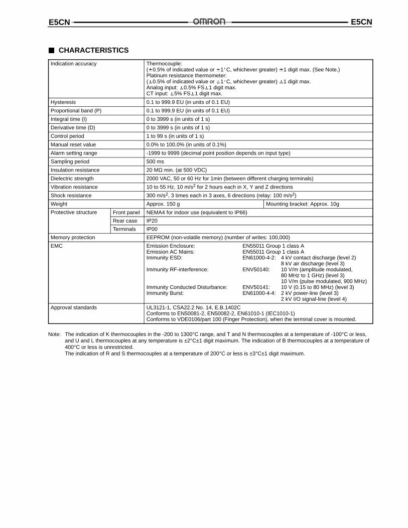
CHARACTERISTICS
Indication accuracy Thermocouple:(0.5% of indicated value or 1C, whichever greater) 1 digit max. (See Note.)Platinum resistance thermometer:(0.5% of indicated value or 1C, whichever greater) 1 digit max.Analog input: 0.5% FS1 digit max.CT input: 5% FS1 digit max.
Hysteresis 0.1 to 999.9 EU (in units of 0.1 EU)
Proportional band (P) 0.1 to 999.9 EU (in units of 0.1 EU)
Integral time (I) 0 to 3999 s (in units of 1 s)
Derivative time (D) 0 to 3999 s (in units of 1 s)
Control period 1 to 99 s (in units of 1 s)
Manual reset value 0.0% to 100.0% (in units of 0.1%)
Alarm setting range -1999 to 9999 (decimal point position depends on input type)
Sampling period 500 ms
Insulation resistance 20 MΩ min. (at 500 VDC)
Dielectric strength 2000 VAC, 50 or 60 Hz for 1min (between different charging terminals)
Vibration resistance 10 to 55 Hz, 10 m/s2 for 2 hours each in X, Y and Z directions
Shock resistance 300 m/s2, 3 times each in 3 axes, 6 directions (relay: 100 m/s2)
Weight Approx. 150 g Mounting bracket: Approx. 10g
Protective structure Front panel NEMA4 for indoor use (equivalent to IP66)
Rear case IP20
Terminals IP00
Memory protection EEPROM (non-volatile memory) (number of writes: 100,000)
EMC Emission Enclosure: EN55011 Group 1 class AEmission AC Mains: EN55011 Group 1 class AImmunity ESD: EN61000-4-2: 4 kV contact discharge (level 2)
8 kV air discharge (level 3)Immunity RF-interference: ENV50140: 10 V/m (amplitude modulated,
80 MHz to 1 GHz) (level 3)10 V/m (pulse modulated, 900 MHz)
Immunity Conducted Disturbance: ENV50141: 10 V (0.15 to 80 MHz) (level 3)Immunity Burst: EN61000-4-4: 2 kV power-line (level 3)
2 kV I/O signal-line (level 4)
Approval standards UL3121-1, CSA22.2 No. 14, E.B.1402CConforms to EN50081-2, EN50082-2, EN61010-1 (IEC1010-1)Conforms to VDE0106/part 100 (Finger Protection), when the terminal cover is mounted.
Note: The indication of K thermocouples in the -200 to 1300°C range, and T and N thermocouples at a temperature of -100°C or less,and U and L thermocouples at any temperature is ±2°C±1 digit maximum. The indication of B thermocouples at a temperature of400°C or less is unrestricted.The indication of R and S thermocouples at a temperature of 200°C or less is ±3°C±1 digit maximum.
E5CNE5CN
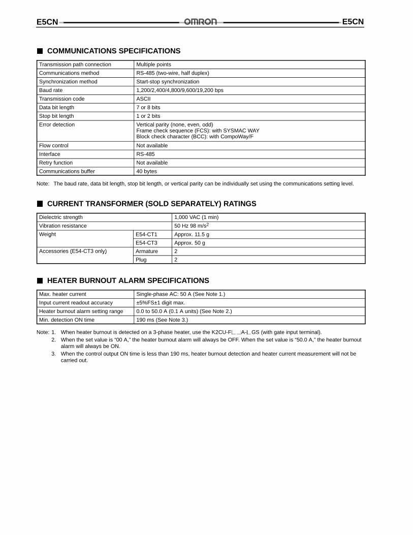
COMMUNICATIONS SPECIFICATIONS
Transmission path connection Multiple points
Communications method RS-485 (two-wire, half duplex)
Synchronization method Start-stop synchronization
Baud rate 1,200/2,400/4,800/9,600/19,200 bps
Transmission code ASCII
Data bit length 7 or 8 bits
Stop bit length 1 or 2 bits
Error detection Vertical parity (none, even, odd)Frame check sequence (FCS): with SYSMAC WAYBlock check character (BCC): with CompoWay/F
Flow control Not available
Interface RS-485
Retry function Not available
Communications buffer 40 bytes
Note: The baud rate, data bit length, stop bit length, or vertical parity can be individually set using the communications setting level.
CURRENT TRANSFORMER (SOLD SEPARATELY) RATINGS
Dielectric strength 1,000 VAC (1 min)
Vibration resistance 50 Hz 98 m/s2
Weight E54-CT1 Approx. 11.5 gg
E54-CT3 Approx. 50 g
Accessories (E54-CT3 only) Armature 2( y)
Plug 2
HEATER BURNOUT ALARM SPECIFICATIONS
Max. heater current Single-phase AC: 50 A (See Note 1.)
Input current readout accuracy ±5%FS±1 digit max.
Heater burnout alarm setting range 0.0 to 50.0 A (0.1 A units) (See Note 2.)
Min. detection ON time 190 ms (See Note 3.)
Note: 1. When heater burnout is detected on a 3-phase heater, use the K2CU-FA-GS (with gate input terminal).2. When the set value is “00 A,” the heater burnout alarm will always be OFF. When the set value is “50.0 A,” the heater burnout
alarm will always be ON.3. When the control output ON time is less than 190 ms, heater burnout detection and heater current measurement will not be
carried out.
E5CN E5CN
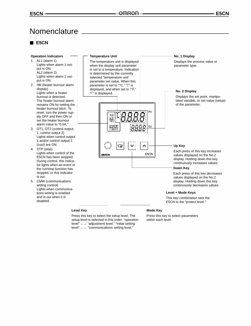
Nomenclature E5CN
Temperature Unit
The temperature unit is displayedwhen the display unit parameteris set to a temperature. Indicationis determined by the currentlyselected “temperature unit”parameter set value. When thisparameter is set to “°C,” “” isdisplayed, and when set to “°F,”“” is displayed.
Operation Indicators1. AL1 (alarm 1)
Lights when alarm 1 out-put is ON.AL2 (alarm 2)Lights when alarm 2 out-put is ON.
2. HB (heater burnout alarmdisplay)Lights when a heaterburnout is detected.The heater burnout alarmremains ON by setting theheater burnout latch. Toreset, turn the power sup-ply OFF and then ON orset the heater burnoutalarm value to “0.0A.”
3. OT1, OT2 (control output1, control output 2)Lights when control output1 and/or control output 2(cool) are ON.
4. STP (stop)Lights when control of theE5CN has been stopped.During control, this indica-tor lights when an event orthe run/stop function hasstopped, or this indicatoris out.
5. CMW (communicationswriting control)Lights when communica-tions writing is enabledand is out when it isdisabled.
No. 1 Display
Displays the process value orparameter type.
No. 2 Display
Displays the set point, manipu-lated variable, or set value (setup)of the parameter.
Up Key
Each press of this key increasesvalues displayed on the No.2display. Holding down this keycontinuously increases values.
Down Key
Each press of this key decreasesvalues displayed on the No.2display. Holding down this keycontinuously decreases values.
Mode Key
Press this key to select parameterswithin each level.
Level Key
Press this key to select the setup level. Thesetup level is selected in this order: “operationlevel” ←→ “adjustment level,” “initial settinglevel” ←→ “communications setting level.”
Level + Mode Keys
This key combination sets theE5CN to the “protect level.”
E5CNE5CN
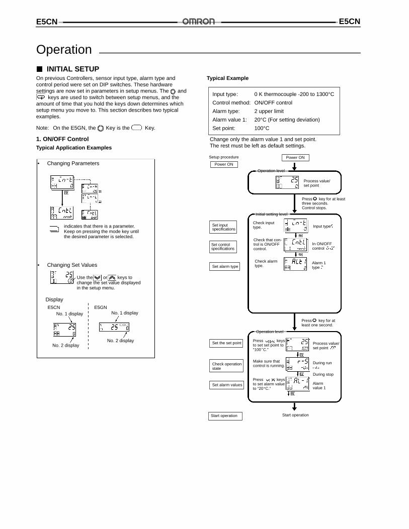
Operation INITIAL SETUPOn previous Controllers, sensor input type, alarm type andcontrol period were set on DIP switches. These hardwaresettings are now set in parameters in setup menus. The and
keys are used to switch between setup menus, and theamount of time that you hold the keys down determines whichsetup menu you move to. This section describes two typicalexamples.
Note: On the E5GN, the Key is the Key.
1. ON/OFF ControlTypical Application Examples
• Changing Parameters
indicates that there is a parameter.Keep on pressing the mode key untilthe desired parameter is selected.
• Changing Set Values
Use the or keys tochange the set value displayedin the setup menu.
DisplayE5CN E5GN
No. 1 display
No. 2 display
No. 1 display
No. 2 display
Typical Example
Input type: 0 K thermocouple -200 to 1300°CControl method: ON/OFF control
Alarm type: 2 upper limit
Alarm value 1: 20°C (For setting deviation)
Set point: 100°C
Change only the alarm value 1 and set point.The rest must be left as default settings.
Setup procedure
Power ON
Set inputspecifications
Set controlspecifications
Set alarm type
Set alarm values
Start operation
Power ON
Process value/set point
Input type
In ON/OFFcontrol
Alarm 1type
Check inputtype.
Check that con-trol is ON/OFFcontrol.
Check alarmtype.
Press key for at leastthree seconds.Control stops.
Process value/set point
Make sure thatcontrol is running.
Press key for atleast one second.
During run
During stop
Alarmvalue 1
Press keysto set set point to“100C.”
Press keysto set alarm valueto “20C.”
Start operation
Set the set point
Check operationstate
Operation level
Initial setting level
Operation level
E5CN E5CN
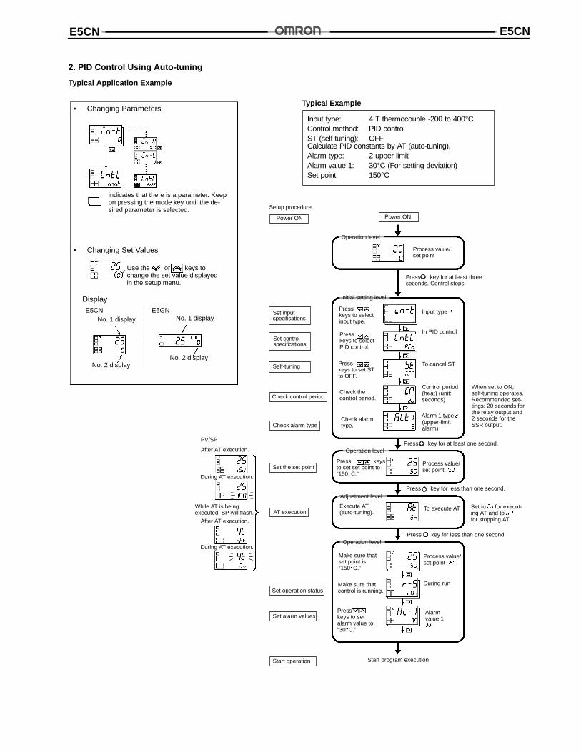
2. PID Control Using Auto-tuning
Typical Application Example
• Changing Parameters
indicates that there is a parameter. Keepon pressing the mode key until the de-sired parameter is selected.
• Changing Set Values
Use the or keys tochange the set value displayedin the setup menu.
DisplayE5CN E5GN
No. 1 display
No. 2 display
No. 1 display
No. 2 display
Input type: 4 T thermocouple -200 to 400°CControl method: PID controlST (self-tuning): OFFCalculate PID constants by AT (auto-tuning).Alarm type: 2 upper limitAlarm value 1: 30°C (For setting deviation)Set point: 150°C
Setup procedure
Power ON
Set inputspecifications
Set controlspecifications
Self-tuning
Set alarm values
Start operation
Power ON
In PID control
To cancel ST
Check thecontrol period.
Check alarmtype.
Press key for at least one second.
Press keysto set set point to“150C.”
Execute AT(auto-tuning).
Presskeys to selectinput type.
Presskeys to selectPID control.
Presskeys to set STto OFF.
Control period(heat) (unit:seconds)
Process value/set point
Press key for less than one second.
To execute AT
Press key for less than one second.
Make sure thatset point is“150C.”
Make sure thatcontrol is running.
Presskeys to setalarm value to“30C.”
Process value/set point
During run
Alarmvalue 1
Start program execution
Check control period
Check alarm type
Set the set point
Set operation status
(upper-limitalarm)
Typical Example
When set to ON,self-tuning operates.Recommended set-tings: 20 seconds forthe relay output and2 seconds for theSSR output.
Set to for execut-ing AT and to
for stopping AT.AT execution
Process value/set point
Input type
Press key for at least threeseconds. Control stops.
Alarm 1 type
After AT execution.
During AT execution.
While AT is beingexecuted, SP will flash.
PV/SP
After AT execution.
During AT execution.
Operation level
Initial setting level
Operation level
Adjustment level
Operation level
E5CNE5CN
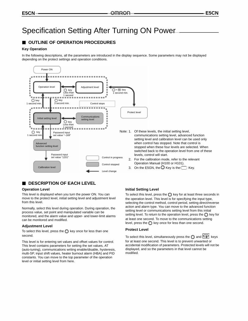
Specification Setting After Turning ON Power OUTLINE OF OPERATION PROCEDURESKey Operation
In the following descriptions, all the parameters are introduced in the display sequence. Some parameters may not be displayeddepending on the protect settings and operation conditions.
Note: 1. Of these levels, the initial setting level,communications setting level, advanced functionsetting level and calibration level can be used onlywhen control has stopped. Note that control isstopped when these four levels are selected. Whenswitched back to the operation level from one of theselevels, control will start.
2. For the calibration mode, refer to the relevantOperation Manual (H100 or H101).
3. On the E5GN, the Key is the Key.
Power ON
Operation level Adjustment level+ key
1 second min.
key1 second min.
key3 second min.
Less than1 second
key
Control stops
Protect level
Communicationssetting levelInitial setting level
key1 second min.
Less than1 second
key
Advancedfunction setting level
Calibration level
Password inputset value “1201”
Password inputset value “--169”
Control in progress
Control stopped
Level change
DESCRIPTION OF EACH LEVELOperation LevelThis level is displayed when you turn the power ON. You canmove to the protect level, initial setting level and adjustment levelfrom this level.
Normally, select this level during operation. During operation, theprocess value, set point and manipulated variable can bemonitored, and the alarm value and upper- and lower-limit alarmscan be monitored and modified.
Adjustment LevelTo select this level, press the key once for less than onesecond.
This level is for entering set values and offset values for control.This level contains parameters for setting the set values, AT(auto-tuning), communications writing enable/disable, hysteresis,multi-SP, input shift values, heater burnout alarm (HBA) and PIDconstants. You can move to the top parameter of the operationlevel or initial setting level from here.
Initial Setting LevelTo select this level, press the key for at least three seconds inthe operation level. This level is for specifying the input type,selecting the control method, control period, setting direct/reverseaction and alarm type. You can move to the advanced functionsetting level or communications setting level from this initialsetting level. To return to the operation level, press the key forat least one second. To move to the communications settinglevel, press the key once for less than one second.
Protect Level
To select this level, simultaneously press the and keysfor at least one second. This level is to prevent unwanted oraccidental modification of parameters. Protected levels will not bedisplayed, and so the parameters in that level cannot bemodified.
E5CN E5CN
Communications Setting LevelTo select this level, press the key once for less than onesecond in the initial setting level. When the communicationsfunction is used, set the communications conditions in this level.Communicating with a personal computer (host computer) allowsset points to be read and written, and manipulated variables to bemonitored.
Advanced Function Setting LevelTo select this level, you must enter the password (“-169”) in theinitial setting level.
You can move only to the calibration level from this level.
This level is for setting the automatic return of display mode, MVlimiter, event input assignment, standby sequence, alarmhysteresis, ST (self-tune) and to move to the user calibrationlevel.
Calibration LevelTo select this level, you must enter the password (“1201”) in theadvanced function setting level. This level is for offsettingdeviation in the input circuit.
You cannot move to other levels by operating the keys on thefront panel from the calibration level. To cancel this level, turn thepower OFF then back ON again.
E5CNE5CN
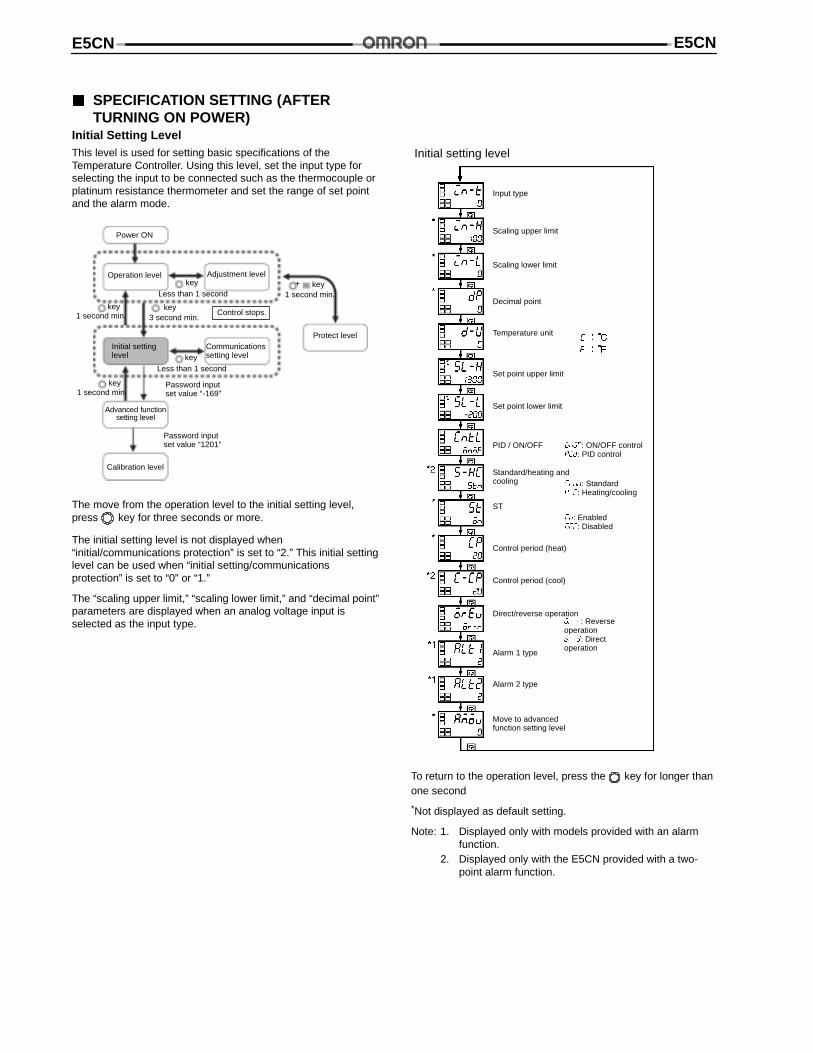
SPECIFICATION SETTING (AFTERTURNING ON POWER)
Initial Setting LevelThis level is used for setting basic specifications of theTemperature Controller. Using this level, set the input type forselecting the input to be connected such as the thermocouple orplatinum resistance thermometer and set the range of set pointand the alarm mode.
Power ON
Operation level Adjustment levelkey
Less than 1 second
key3 second min.
key1 second min.
Communicationssetting levelkey
Less than 1 second
Control stops.
Initial settinglevel
key1 second min.
Password inputset value “-169”
Password inputset value “1201”
Advanced functionsetting level
Calibration level
Protect level
key1 second min.
+
The move from the operation level to the initial setting level,press key for three seconds or more.
The initial setting level is not displayed when“initial/communications protection” is set to “2.” This initial settinglevel can be used when “initial setting/communicationsprotection” is set to “0” or “1.”
The “scaling upper limit,” “scaling lower limit,” and “decimal point”parameters are displayed when an analog voltage input isselected as the input type.
Initial setting level
Input type
Scaling upper limit
Scaling lower limit
Decimal point
Set point upper limit
Set point lower limit
PID / ON/OFF
Standard/heating andcooling
ST
Control period (heat)
Control period (cool)
Direct/reverse operation
Alarm 1 type
Alarm 2 type
Move to advancedfunction setting level
Temperature unit
: ON/OFF control : PID control
: Standard: Heating/cooling
: Enabled: Disabled
: Reverseoperation: Directoperation
To return to the operation level, press the key for longer thanone second
*Not displayed as default setting.
Note: 1. Displayed only with models provided with an alarmfunction.
2. Displayed only with the E5CN provided with a two-point alarm function.
E5CN E5CN
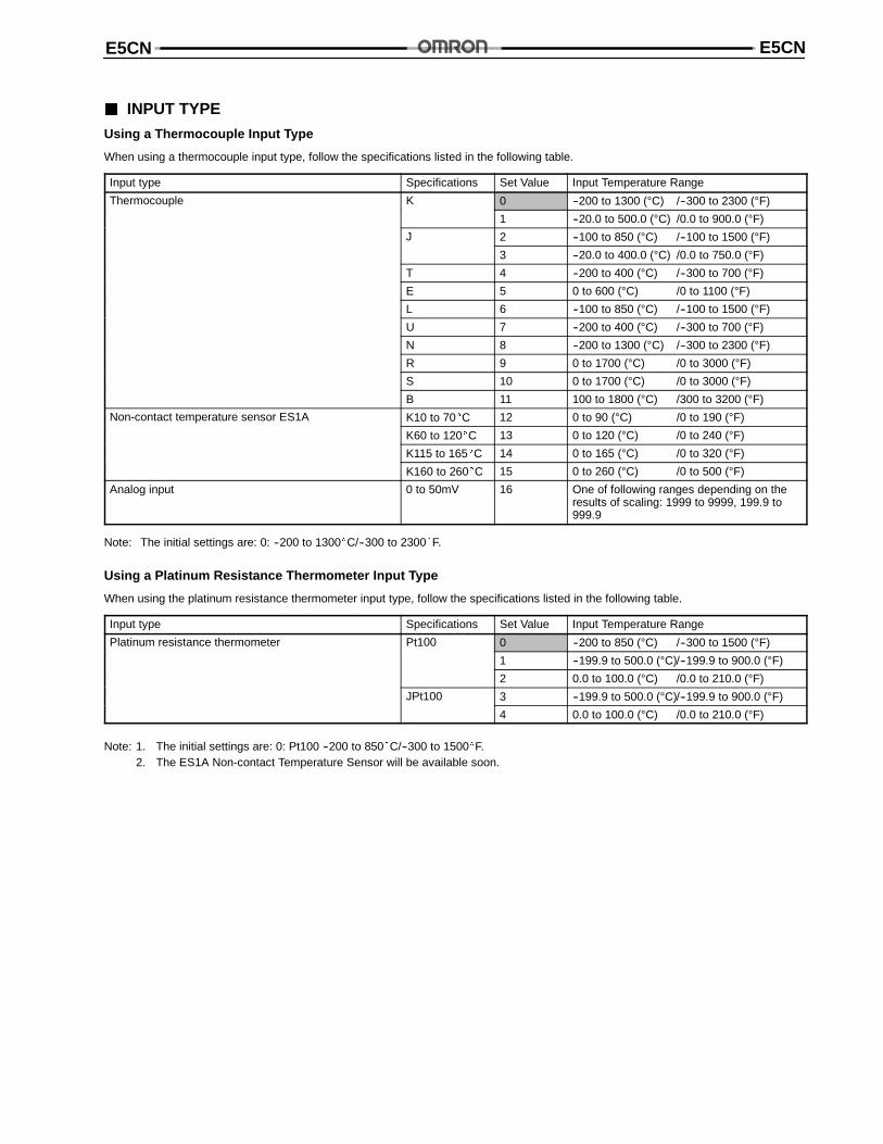
INPUT TYPE
Using a Thermocouple Input Type
When using a thermocouple input type, follow the specifications listed in the following table.
Input type Specifications Set Value Input Temperature Range
Thermocouple K 0 --200 to 1300 (°C) /--300 to 2300 (°F)
1 --20.0 to 500.0 (°C) /0.0 to 900.0 (°F)
J 2 --100 to 850 (°C) /--100 to 1500 (°F)
3 --20.0 to 400.0 (°C) /0.0 to 750.0 (°F)
T 4 --200 to 400 (°C) /--300 to 700 (°F)
E 5 0 to 600 (°C) /0 to 1100 (°F)
L 6 --100 to 850 (°C) /--100 to 1500 (°F)
U 7 --200 to 400 (°C) /--300 to 700 (°F)
N 8 --200 to 1300 (°C) /--300 to 2300 (°F)
R 9 0 to 1700 (°C) /0 to 3000 (°F)
S 10 0 to 1700 (°C) /0 to 3000 (°F)
B 11 100 to 1800 (°C) /300 to 3200 (°F)
Non-contact temperature sensor ES1A K10 to 70C 12 0 to 90 (°C) /0 to 190 (°F)
K60 to 120C 13 0 to 120 (°C) /0 to 240 (°F)
K115 to 165C 14 0 to 165 (°C) /0 to 320 (°F)
K160 to 260C 15 0 to 260 (°C) /0 to 500 (°F)
Analog input 0 to 50mV 16 One of following ranges depending on theresults of scaling: 1999 to 9999, 199.9 to999.9
Note: The initial settings are: 0: --200 to 1300C/--300 to 2300F.
Using a Platinum Resistance Thermometer Input Type
When using the platinum resistance thermometer input type, follow the specifications listed in the following table.
Input type Specifications Set Value Input Temperature Range
Platinum resistance thermometer Pt100 0 --200 to 850 (°C) /--300 to 1500 (°F)
1 --199.9 to 500.0 (°C)/--199.9 to 900.0 (°F)
2 0.0 to 100.0 (°C) /0.0 to 210.0 (°F)
JPt100 3 --199.9 to 500.0 (°C)/--199.9 to 900.0 (°F)
4 0.0 to 100.0 (°C) /0.0 to 210.0 (°F)
Note: 1. The initial settings are: 0: Pt100 --200 to 850C/--300 to 1500F.2. The ES1A Non-contact Temperature Sensor will be available soon.
E5CNE5CN
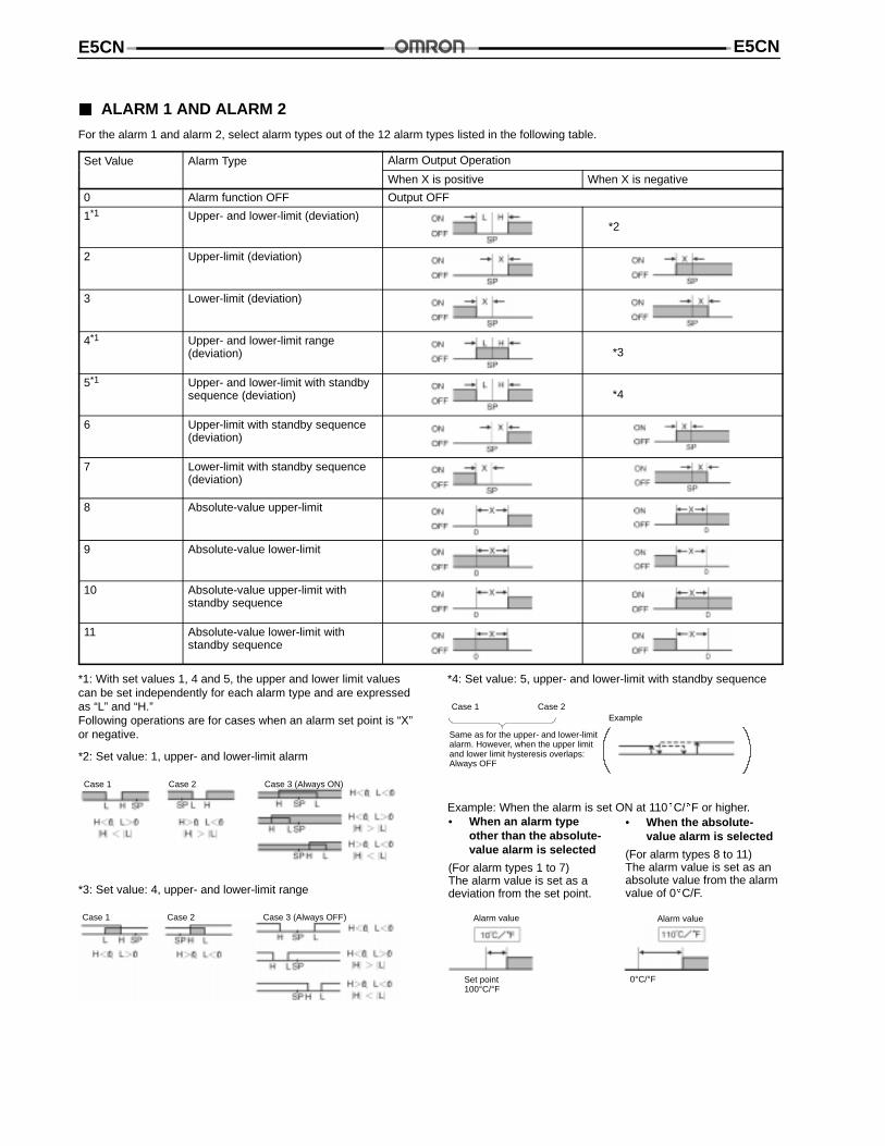
ALARM 1 AND ALARM 2
For the alarm 1 and alarm 2, select alarm types out of the 12 alarm types listed in the following table.
Set Value Alarm Type Alarm Output Operationy
When X is positive When X is negative
0 Alarm function OFF Output OFF
1*1 Upper- and lower-limit (deviation)*2
2 Upper-limit (deviation)
3 Lower-limit (deviation)
4*1 Upper- and lower-limit range(deviation) *3
5*1 Upper- and lower-limit with standbysequence (deviation) *4
6 Upper-limit with standby sequence(deviation)
7 Lower-limit with standby sequence(deviation)
8 Absolute-value upper-limit
9 Absolute-value lower-limit
10 Absolute-value upper-limit withstandby sequence
11 Absolute-value lower-limit withstandby sequence
*1: With set values 1, 4 and 5, the upper and lower limit valuescan be set independently for each alarm type and are expressedas “L” and “H.”Following operations are for cases when an alarm set point is “X”or negative.
*2: Set value: 1, upper- and lower-limit alarm
Case 1 Case 2 Case 3 (Always ON)
*3: Set value: 4, upper- and lower-limit range
Case 1 Case 2 Case 3 (Always OFF)
*4: Set value: 5, upper- and lower-limit with standby sequence
Case 1 Case 2
Same as for the upper- and lower-limitalarm. However, when the upper limitand lower limit hysteresis overlaps:Always OFF
Example
Example: When the alarm is set ON at 110C/F or higher.• When an alarm type
other than the absolute-value alarm is selected
(For alarm types 1 to 7)The alarm value is set as adeviation from the set point.
• When the absolute-value alarm is selected
(For alarm types 8 to 11)The alarm value is set as anabsolute value from the alarmvalue of 0C/F.
Alarm value
Set point100°C/°F
Alarm value
0°C/°F
E5CN E5CN
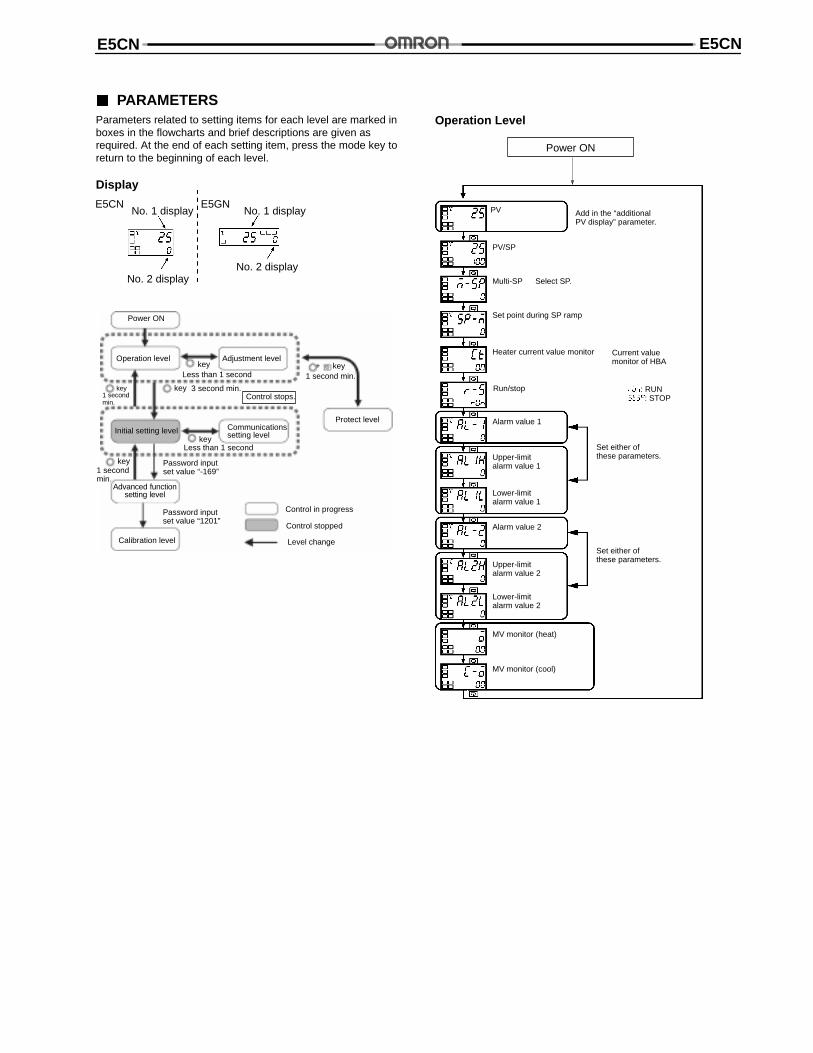
PARAMETERSParameters related to setting items for each level are marked inboxes in the flowcharts and brief descriptions are given asrequired. At the end of each setting item, press the mode key toreturn to the beginning of each level.
Display
E5CN E5GNNo. 1 display
No. 2 display
No. 1 display
No. 2 display
Password inputset value “1201”
Advanced functionsetting level
Calibration level
Password inputset value “-169”
Control stops.
Initial setting level
Less than 1 secondkey
Communicationssetting level
Power ON
Operation level
1 second min.+ key
Protect level
Control in progress
Control stopped
Adjustment level
1 secondmin.
key
1 secondmin.
key
3 second min.key
Level change
Less than 1 secondkey
Operation Level
PV
PV/SP
Add in the “additionalPV display” parameter.
Multi-SP
Set point during SP ramp
Heater current value monitor
Run/stop
Alarm value 1
Upper-limitalarm value 1
Lower-limitalarm value 1
Set either ofthese parameters.
Alarm value 2
Upper-limitalarm value 2
Lower-limitalarm value 2
Set either ofthese parameters.
MV monitor (heat)
MV monitor (cool)
Current valuemonitor of HBA
Select SP.
: RUN: STOP
Power ON
E5CNE5CN
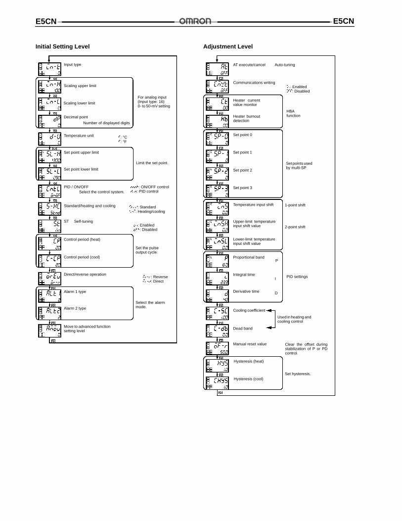
Initial Setting Level
Input type
Scaling upper limit
Decimal point
Temperature unit
Set point upper limit
PID / ON/OFF
Standard/heating and cooling
ST
Control period (heat)
Alarm 1 type
Move to advanced functionsetting level
Set the pulseoutput cycle.
Direct/reverse operation
Alarm 2 type
Limit the set point.
Select the control system.
Self-tuning
Select the alarmmode.
Control period (cool)
For analog input(Input type: 16)0- to 50-mV setting
Number of displayed digits
: °C: °F
: ON/OFF control : PID control
: Standard: Heating/cooling
: Enabled: Disabled
: Reverse: Direct
Set point lower limit
Scaling lower limit
Adjustment Level
Hysteresis (heat)
AT execute/cancel
Communications writing
Heater currentvalue monitor
HBAfunction
Set point 0
Set point 1
Set points usedby multi-SP
Temperature input shift 1-point shift
2-point shift
Proportional band
PID settings
Cooling coefficient
Dead band
Used in heating andcooling control
Manual reset value
Auto-tuning
Heater burnoutdetection
Set point 2
Set point 3
Lower-limit temperatureinput shift value
Upper-limit temperatureinput shift value
Derivative time
Integral time
Clear the offset duringstabilization of P or PDcontrol.
Set hysteresis.
P
I
D
Hysteresis (cool)
: Enabled: Disabled
E5CN E5CN
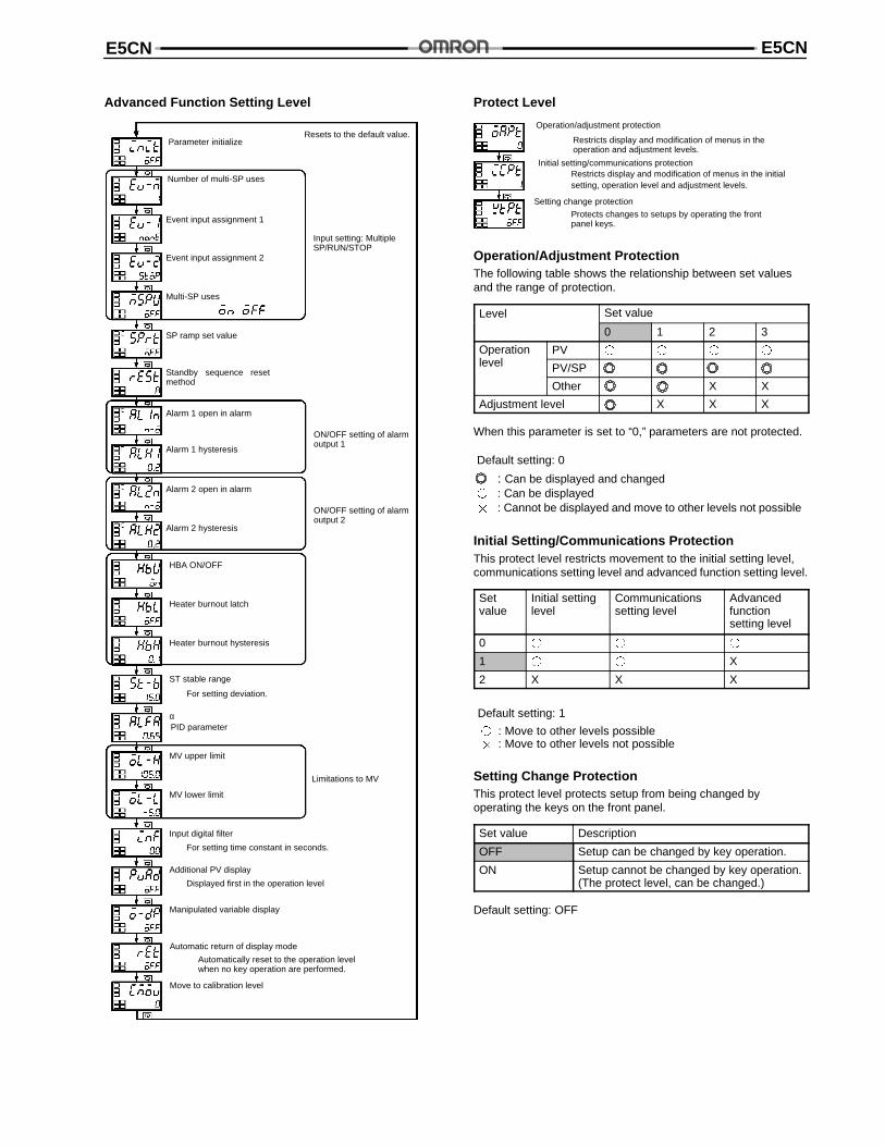
Advanced Function Setting Level
Parameter initialize
Alarm 2 hysteresis
Alarm 2 open in alarm
Alarm 1 hysteresis
Alarm 1 open in alarm
Standby sequence resetmethod
Multi-SP uses
Event input assignment 2
Event input assignment 1
Number of multi-SP uses
HBA ON/OFF
Move to calibration level
Automatic return of display mode
Manipulated variable display
Additional PV display
Input digital filter
MV upper limit
α
ST stable range
Heater burnout hysteresis
Heater burnout latch
MV lower limit
SP ramp set value
Input setting: MultipleSP/RUN/STOP
Resets to the default value.
ON/OFF setting of alarmoutput 1
ON/OFF setting of alarmoutput 2
PID parameter
Limitations to MV
Displayed first in the operation level
Automatically reset to the operation levelwhen no key operation are performed.
For setting time constant in seconds.
For setting deviation.
Protect Level
Operation/adjustment protection
Restricts display and modification of menus in theoperation and adjustment levels.
Initial setting/communications protectionRestricts display and modification of menus in the initialsetting, operation level and adjustment levels.
Setting change protection
Protects changes to setups by operating the frontpanel keys.
Operation/Adjustment ProtectionThe following table shows the relationship between set valuesand the range of protection.
Level Set value
0 1 2 3
Operationl l
PV
level PV/SP
Other X X
Adjustment level X X X
When this parameter is set to “0,” parameters are not protected.
Default setting: 0
: Can be displayed and changed : Can be displayed : Cannot be displayed and move to other levels not possible
Initial Setting/Communications ProtectionThis protect level restricts movement to the initial setting level,communications setting level and advanced function setting level.
Setvalue
Initial settinglevel
Communicationssetting level
Advancedfunctionsetting level
0
1 X
2 X X X
Default setting: 1
: Move to other levels possible : Move to other levels not possible
Setting Change ProtectionThis protect level protects setup from being changed byoperating the keys on the front panel.
Set value Description
OFF Setup can be changed by key operation.
ON Setup cannot be changed by key operation.(The protect level, can be changed.)
Default setting: OFF
E5CNE5CN
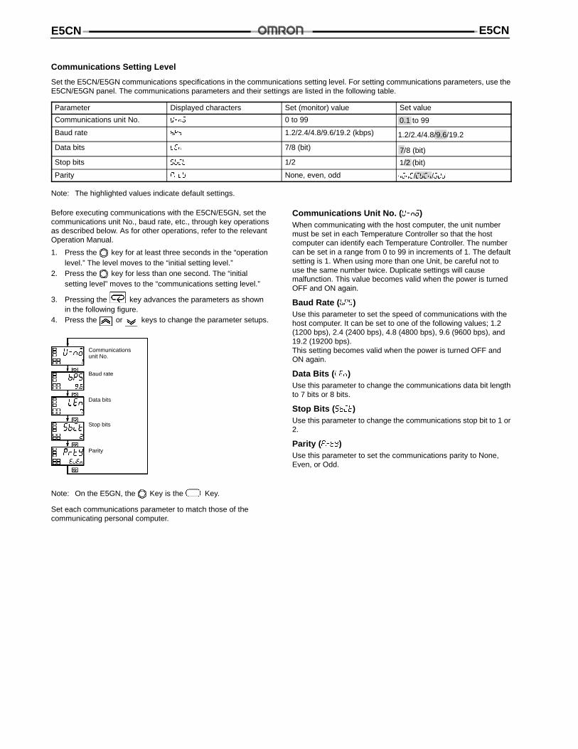
Communications Setting Level
Set the E5CN/E5GN communications specifications in the communications setting level. For setting communications parameters, use theE5CN/E5GN panel. The communications parameters and their settings are listed in the following table.
Parameter Displayed characters Set (monitor) value Set value
Communications unit No. 0 to 99 0.1 to 99
Baud rate 1.2/2.4/4.8/9.6/19.2 (kbps) 1.2/2.4/4.8/9.6/19.2
Data bits 7/8 (bit) 7/8 (bit)
Stop bits 1/2 1/2 (bit)
Parity None, even, odd //
Note: The highlighted values indicate default settings.
Before executing communications with the E5CN/E5GN, set thecommunications unit No., baud rate, etc., through key operationsas described below. As for other operations, refer to the relevantOperation Manual.
1. Press the key for at least three seconds in the “operationlevel.” The level moves to the “initial setting level.”
2. Press the key for less than one second. The “initialsetting level” moves to the “communications setting level.”
3. Pressing the key advances the parameters as shownin the following figure.
4. Press the or keys to change the parameter setups.
Communicationsunit No.
Baud rate
Data bits
Stop bits
Parity
Note: On the E5GN, the Key is the Key.
Set each communications parameter to match those of thecommunicating personal computer.
Communications Unit No. ( )When communicating with the host computer, the unit numbermust be set in each Temperature Controller so that the hostcomputer can identify each Temperature Controller. The numbercan be set in a range from 0 to 99 in increments of 1. The defaultsetting is 1. When using more than one Unit, be careful not touse the same number twice. Duplicate settings will causemalfunction. This value becomes valid when the power is turnedOFF and ON again.
Baud Rate ( )Use this parameter to set the speed of communications with thehost computer. It can be set to one of the following values; 1.2(1200 bps), 2.4 (2400 bps), 4.8 (4800 bps), 9.6 (9600 bps), and19.2 (19200 bps).This setting becomes valid when the power is turned OFF andON again.
Data Bits ( )Use this parameter to change the communications data bit lengthto 7 bits or 8 bits.
Stop Bits ( )Use this parameter to change the communications stop bit to 1 or2.
Parity ( )Use this parameter to set the communications parity to None,Even, or Odd.
E5CN E5CN
TROUBLESHOOTING
When an error occurs, an error code will be displayed on the No. 1 display. Check the contents of an error and take appropriatecountermeasures.
No. 1 display Type of error Countermeasures
Input error Check the wiring of inputs for miswiring, disconnections, short-circuits, and the inputtype.
Memory error First, turn the power OFF then back ON again. If the display remains the same, theUnit must be repaired. If the display is restored, then a probable cause can be externalnoise affecting the control system. Check for external noise.
Display range over Though not error, this is displayed when the process value exceeds the display rangewhen the control range is larger than the display range.
• When less than “-1999”
• When larger than “9999”
HB error First, turn the power OFF then back ON again. If the display remains the same, thecontroller must be repaired. If the display is restored, then a probable cause can beelectrical noise affecting the control system. Check for electrical noise.
Note: Error will be displayed only when the display is set for the PV or PV/SP.
Fuzzy Self-tuningThe fuzzy self-tuning (ST) is a function that automatically calculates an optimum PID constant depending on items to be controlled.
FEATURE
The Temperature Controller determines when to execute this fuzzy self-tuning.
FUNCTIONS
SRT: Performs PID tuning according to the step response method when the SP is changed.
LCT: Performs PID tuning according to the limit cycle method when the SP is changed.
Requirements for SRT Functionality
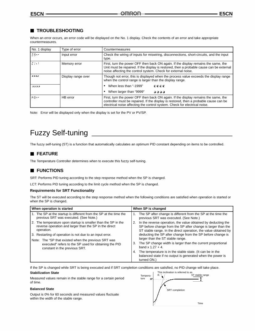
The ST will be executed according to the step response method when the following conditions are satisfied when operation is started orwhen the SP is changed.
When operation is started When SP is changed
1. The SP at the startup is different from the SP at the time theprevious SRT was executed. (See Note.)
2. The temperature upon startup is smaller than the SP in thereverse operation and larger than the SP in the directoperation.
3. Restarting of operation is not due to an input error.
Note: The “SP that existed when the previous SRT wasexecuted” refers to the SP used for obtaining the PIDconstant in the previous SRT.
1. The SP after change is different from the SP at the time theprevious SRT was executed. (See Note.)
2. In the reverse operation, the value obtained by deducting theSP before change from the SP after change is larger than theST stable range. In the direct operation, the value obtained bydeducting the SP after change from the SP before change islarger than the ST stable range.
3. The SP change width is larger than the current proportionalband x 1.27 + 4.
4. The temperature is in the stable state. (It can be in thebalanced state if no output is generated when the power isturned ON.)
If the SP is changed while SRT is being executed and if SRT completion conditions are satisfied, no PID change will take place.
Stabilization State
Measured values remain in the stable range for a certain periodof time.
Balanced State
Output is 0% for 60 seconds and measured values fluctuatewithin the width of the stable range.
Tempera-ture
SRT completion
Time
ST stable rangeThis inclination is referred to asR.
E5CNE5CN
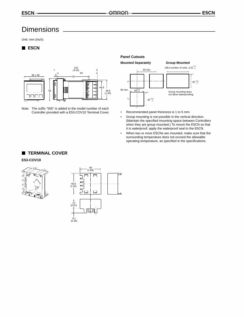
DimensionsUnit: mm (inch)
E5CN
• Recommended panel thickness is 1 to 5 mm.
• Group mounting is not possible in the vertical direction.(Maintain the specified mounting space between Controllerswhen they are group mounted.) To mount the E5CN so thatit is waterproof, apply the waterproof seal to the E5CN.
• When two or more E5CNs are mounted, make sure that thesurrounding temperature does not exceed the allowableoperating temperature, as specified in the specifications.
(48number of units -2.5)60 min.
60 min.
+1.00
45
45
45 +0.60
+0.60
+0.60
Panel Cutouts
Group mounting doesnot allow waterproofing.
Mounted Separately Group Mounted
Note: The suffix “500” is added to the model number of eachController provided with a E53-COV10 Terminal Cover.
48 x 48
102(4.02)
93
789
5844.8
48.8(1.92)
TERMINAL COVER
E53-COV10
48.8(1.92)
22(0.87)
48(1.89)
9.1(0.36)
E5CN E5CN
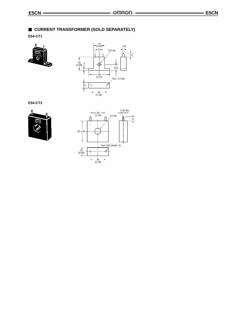
CURRENT TRANSFORMER (SOLD SEPARATELY)
E54-CT1
5.8 dia.
Two, 3.5 dia.
21(0.83)
30(1.18)
10
40(1.57)
25(0.98)
3
15
10.5
7.5
2.8
E54-CT3
12 dia.
Two, M3 (depth: 4)
40 x 40
2.36 dia.
30(1.18)
15(0.59)
30(1.18)
9
E5CNE5CN
Installation
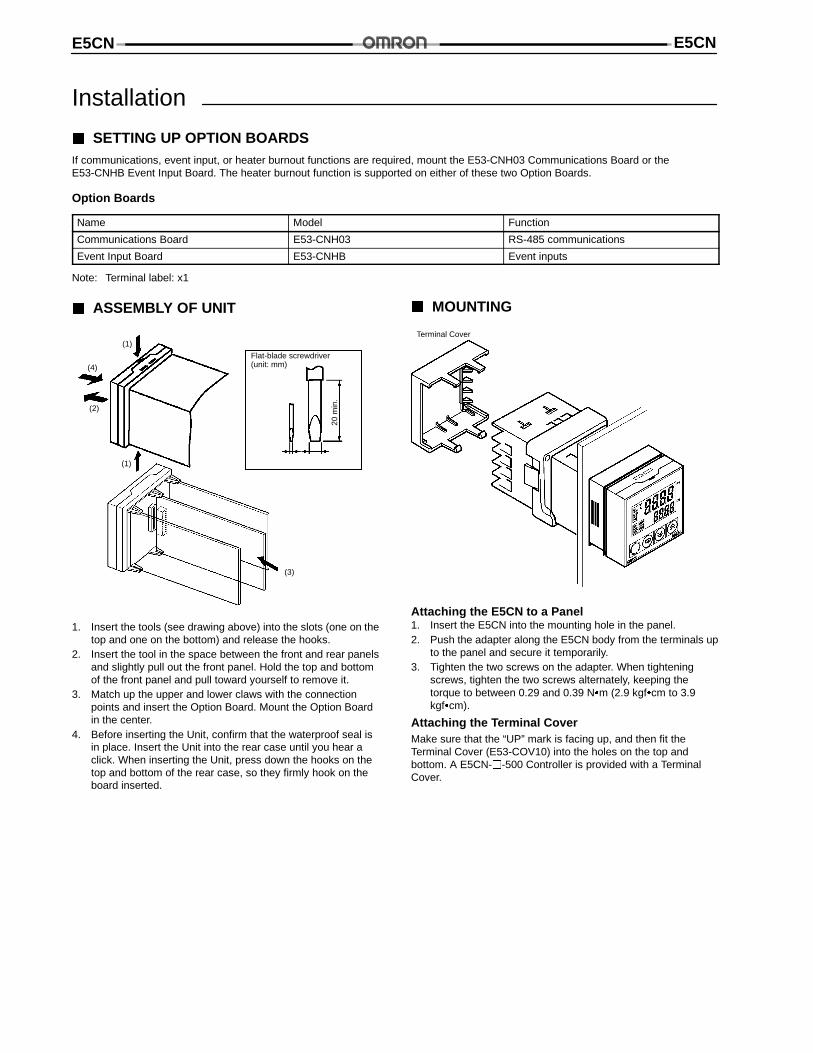
SETTING UP OPTION BOARDSIf communications, event input, or heater burnout functions are required, mount the E53-CNH03 Communications Board or theE53-CNHB Event Input Board. The heater burnout function is supported on either of these two Option Boards.
Option Boards
Name Model Function
Communications Board E53-CNH03 RS-485 communications
Event Input Board E53-CNHB Event inputs
Note: Terminal label: x1
ASSEMBLY OF UNIT
Flat-blade screwdriver(unit: mm)
20m
in.
(1)
(1)
(2)
(4)
(3)
1. Insert the tools (see drawing above) into the slots (one on thetop and one on the bottom) and release the hooks.
2. Insert the tool in the space between the front and rear panelsand slightly pull out the front panel. Hold the top and bottomof the front panel and pull toward yourself to remove it.
3. Match up the upper and lower claws with the connectionpoints and insert the Option Board. Mount the Option Boardin the center.
4. Before inserting the Unit, confirm that the waterproof seal isin place. Insert the Unit into the rear case until you hear aclick. When inserting the Unit, press down the hooks on thetop and bottom of the rear case, so they firmly hook on theboard inserted.
MOUNTING
Terminal Cover
Attaching the E5CN to a Panel1. Insert the E5CN into the mounting hole in the panel.2. Push the adapter along the E5CN body from the terminals up
to the panel and secure it temporarily.3. Tighten the two screws on the adapter. When tightening
screws, tighten the two screws alternately, keeping thetorque to between 0.29 and 0.39 Nm (2.9 kgfcm to 3.9kgfcm).
Attaching the Terminal CoverMake sure that the “UP” mark is facing up, and then fit theTerminal Cover (E53-COV10) into the holes on the top andbottom. A E5CN--500 Controller is provided with a TerminalCover.
E5CN E5CN
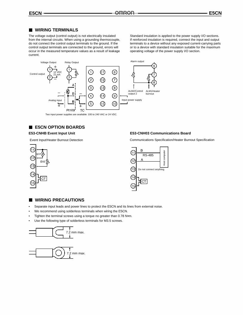
WIRING TERMINALSThe voltage output (control output) is not electrically insulatedfrom the internal circuits. When using a grounding thermocouple,do not connect the control output terminals to the ground. If thecontrol output terminals are connected to the ground, errors willoccur in the measured temperature values as a result of leakagecurrent.
Standard insulation is applied to the power supply I/O sections.If reinforced insulation is required, connect the input and outputterminals to a device without any exposed current-carrying partsor to a device with standard insulation suitable for the maximumoperating voltage of the power supply I/O section.
Control output
Analog input Input power supply
Alarm output
ALM1/Heaterburnout
ALM2/Controloutput 2
Two input power supplies are available: 100 to 240 VAC or 24 VDC.
Voltage Output Relay Output
12 VDC21 mA
E5CN OPTION BOARDSE53-CNHB Event Input Unit
Event Input/Heater Burnout Detection
E53-CNH03 Communications Board
Communications Specification/Heater Burnout Specification
Do not connect anything.
Hos
tcom
pute
r
RS-485
WIRING PRECAUTIONS• Separate input leads and power lines to protect the E5CN and its lines from external noise.
• We recommend using solderless terminals when wiring the E5CN.
• Tighten the terminal screws using a torque no greater than 0.78 Nm.
• Use the following type of solderless terminals for M3.5 screws.
7.2 mm max.
7.2 mm max.
E5CNE5CN
Precautions
OPERATING ENVIRONMENT• Use the Temperature Controller within the rated operating
temperature, storage temperature, and operating humidityspecified for each model.
• Use the Temperature Controller according to the perfor-mance specifications such as vibration, shock, and degree ofprotection specified for each model.
• Do not use the Temperature Controller in places where it issubject to dust or corrosive gases.
• Install the Temperature Controller away from the devices thatgenerate high-frequency noise.
SERVICE LIFE
The service life of relays used for the control output or alarmoutput varies depending on mostly switching conditions. Be sureto confirm their performance under actual operating conditionsand do not use them beyond the allowable number of switchings.If they are used in a deteriorated condition, insulation betweencircuits may be damaged and, as a result, the TemperatureController itself may be damaged or burned.
The service life of electronic devices such as TemperatureControllers is determined not only by the number of switchings ofrelays, but also by the service life of internal electroniccomponents. The component service life is affected by theambient temperature: the higher the temperature becomes, theshorter the service life becomes; the lower the temperaturebecomes, the longer the service life becomes. For this reason,the service life can be extended by lowering the internaltemperature of the Temperature Controller.
When two or more Temperature Controllers are mountedhorizontally close to each other or vertically next to each other,the internal temperature will increase, due to heat radiated by theTemperature Controllers, and the service life will decrease. Inthese situations, forced cooling by fans or other means of airventilation will be required to cool down the TemperatureControllers. When providing forced cooling, however, be carefulnot to cool down the terminals solely, to avoid measurementerrors.
ORDERING PRECAUTIONS
Units separately sold, such as Control Output Units and CurrentTransformers, are specified for each Temperature Controller. Besure to order appropriate units according to the application.
INSTALLATION
MountingMount the Temperature Controller horizontally level.
ConnectionWhen extending or connecting the thermocouple lead wire, besure to use compensating wires that match the thermocoupletypes.
When extending or connecting the lead wire of the platinumresistance thermometer, be sure to use wires that have lowresistance.
When wiring the platinum resistance thermometer to theTemperature Controller, keep the wire route as short as possible.Separate this wiring away from the power supply wiring and loadwiring to avoid inductive or other forms of noise.
Do not use empty terminals.
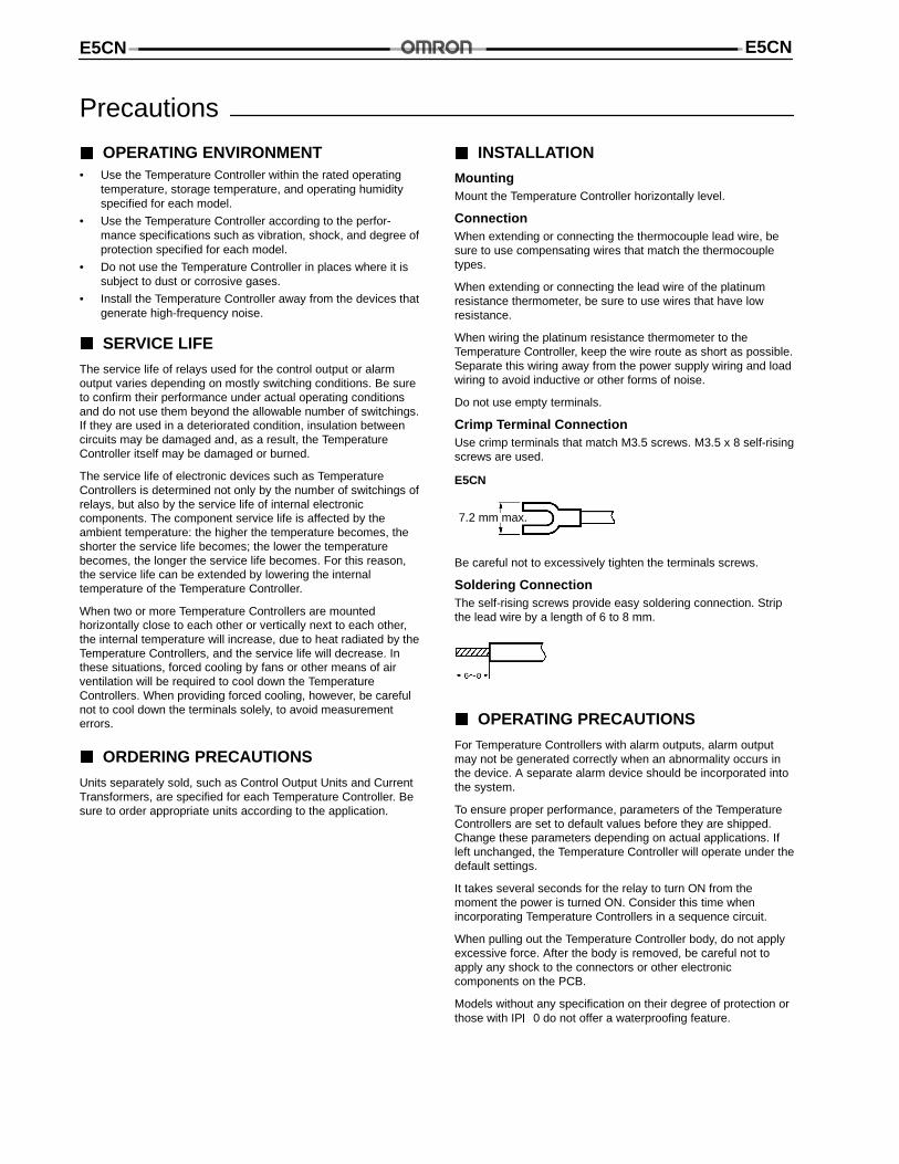
Crimp Terminal ConnectionUse crimp terminals that match M3.5 screws. M3.5 x 8 self-risingscrews are used.
E5CN
7.2 mm max.
Be careful not to excessively tighten the terminals screws.
Soldering ConnectionThe self-rising screws provide easy soldering connection. Stripthe lead wire by a length of 6 to 8 mm.
OPERATING PRECAUTIONS
For Temperature Controllers with alarm outputs, alarm outputmay not be generated correctly when an abnormality occurs inthe device. A separate alarm device should be incorporated intothe system.
To ensure proper performance, parameters of the TemperatureControllers are set to default values before they are shipped.Change these parameters depending on actual applications. Ifleft unchanged, the Temperature Controller will operate under thedefault settings.
It takes several seconds for the relay to turn ON from themoment the power is turned ON. Consider this time whenincorporating Temperature Controllers in a sequence circuit.
When pulling out the Temperature Controller body, do not applyexcessive force. After the body is removed, be careful not toapply any shock to the connectors or other electroniccomponents on the PCB.
Models without any specification on their degree of protection orthose with IP0 do not offer a waterproofing feature.

E5CN E5CN
Cat. No. GCTC12 1/99 Specifications subject to change without notice. Printed in U.S.A.
Omron Europe B.V. EMA-ISD, tel:+31 23 5681390, fax:+31 23 5681397, http://www.eu.omron.com/ema