Embed Size (px)
Citation preview

Digital Multimeters -
Fundamentals
ni.com/training
Chinmay Anand Misra
Certified LabVIEW Developer
Staff Applications Engineer

Agenda
• Introduction
• Understanding DMM specifications (accuracy, resolution,
sensitivity)
• Setting up signal connections to the hardware
ni.com/training
• Setting up signal connections to the hardware
• Using LabVIEW to program DMM applications
• Using the functions on the NI-DMM function palette

DMM Instrumentation
ni.com/training
Handheld DMMs• 3½ - 5½ digits
• Portable, general purpose
• Most Common
Benchtop DMMs• 5½ - 8½ digits
• Stationary, dedicated
• Sometimes programmed
with GPIB, LAN, USB, Serial
NI DMMs• 5½ - 7½ digits
•Stationary or Portable
• PCI, PXI, USB,
• Used with LabVIEW or
text-based languages for
Automated Test

DMM Instrumentation• Digital Multimeters (DMMs) are specialized in taking
flexible, high resolution measurements
• Low to medium acquisition speeds
• High resolution
• Measures current or resistance in addition to voltage
ni.com/training
• Measures current or resistance in addition to voltage
• Different form factors: PXI, PCIe, PCI, USB

DMMs vs. Multifunction DAQ
• Multiple Measurement Types
• Higher resolution
• Higher voltage and current ranges
• Higher level of signal conditioning and isolation
ni.com/training
• Higher level of signal conditioning and isolation
• DMMs do not specify a reading rate
• Reading rate is dependent on configuration

B. DMMs vs. Multifunction DAQ (cont) - Hidden
ni.com/training

Common Measurements
Primarily used for high resolution, slow sampling rate
applications
DC Measurements AC Measurement
Voltage RMS Voltage
ni.com/training
Voltage
Current
Resistance
Diode Measurement
RMS Voltage
RMS Current
Capacitance
Inductance

Benefits of NI DMMs
Software Support in NI LabVIEW and SignalExpress
The NI 407x series of DMMs offer unique capabilities
− Isolated Digitizer Mode at up to 1.8 MS/s
− Industry Leading Accuracy
− 2-year Calibration Cycle
ni.com/training
− 2-year Calibration Cycle
• USB-4065 & PCMCIA-4050 for portable measurements

Accuracy
Accuracy represents the uncertainty of a given measurement
Device Uncertainty is usually specified by the manufacturer in
three ways:
• (% Reading) + Offset
ni.com/training
• (% Reading) + Offset
• (% Reading) + (% Range)
• ±(ppm of reading + ppm of range)
• 1 ppm = 0.0001%
where ppm is parts per million
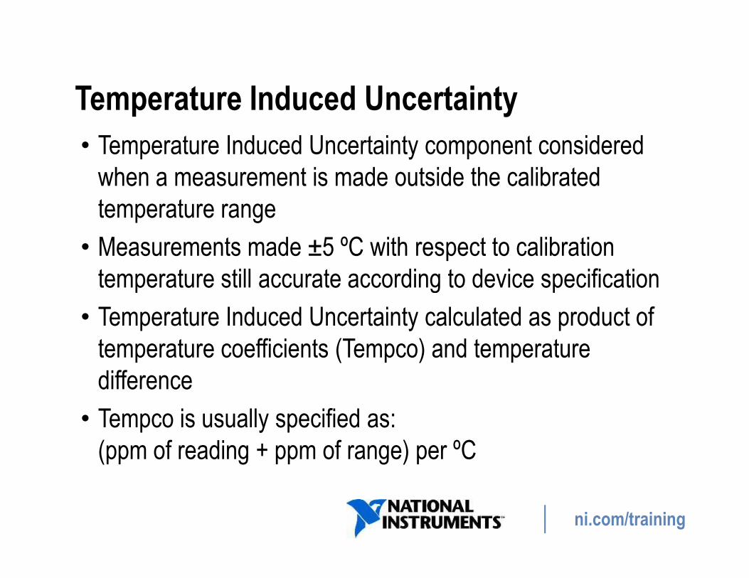
Temperature Induced Uncertainty
• Temperature Induced Uncertainty component considered
when a measurement is made outside the calibrated
temperature range
• Measurements made ±5 ºC with respect to calibration
temperature still accurate according to device specification
ni.com/training
temperature still accurate according to device specification
• Temperature Induced Uncertainty calculated as product of
temperature coefficients (Tempco) and temperature
difference
• Tempco is usually specified as:
(ppm of reading + ppm of range) per ºC

Calculating Accuracy: Example 1
Consider a measurement:
• Made with NI 4070 calibrated at 23 ºC
• 6½ digit measurement of 5 VDC signal
ni.com/training
• 6½ digit measurement of 5 VDC signal
• Selected 10 V range
• Within 2-year period of last calibration
What is the accuracy?

Calculating Accuracy: Example 1 Answer
ni.com/training
Accuracy = ±(ppm of reading + ppm of range)
= ± (25 ppm x 5 V + 6 ppm x 10 V)
= ±185 µV

Calculating Accuracy: Example 2
Consider taking a measurement in 38 ºC temperature.
ni.com/training
Temperature Induced Uncertainty must be considered.
Accuracy = ± (25ppm of 5V + 6 ppm of 10V)
+ [(1ppm x 5V + 1ppm x 10V) × (38-(23+5))] = ±335µV

Resolution
Resolution is the smallest change in an input signal that
produces a change in the output.
Resolution is specified by the manufacturer in three units:
ni.com/training
• Bits
• Absolute Units of Resolution (AUR)
• Digits of Resolution

Bits of Resolution
In an ideal situation, only quantization noise is present, so
resolution can be represented as bits of resolution.
Bits of resolution refers to the number of bits on the analog-
to-digital converter (ADC).
ni.com/training
to-digital converter (ADC).

Absolute Units of Resolution
Absolute unit of resolution represents the minimum change in
voltage a device can measure.
For a given voltage measurement range, the [noise-free]
ni.com/training
For a given voltage measurement range, the [noise-free]
absolute unit of resolution is:
Total span for the Given Range (in volts)
____________________________________
Number of ADC quantization Levels (counts)

Digits of Resolution
Traditionally, 6½ digits referred to the number of digits displayed on the
readout of boxed instruments.
Now, Digits of Resolution is a calculation.
6½ Digit DMM
ni.com/training
Full Digits (0-9): 6
Half Digit (0 or 1) : 1
09.99998 V DC
V
Ω
A Hz
L C
6½ Digit DMM

Noise and Digits of Resolution
• Real-world systems, noise must be considered.
• Higher level of noise produces lower effective resolution.
• Effective Number of Digits (ENOD) includes this noise.
• For example, a DMM ideally with 6 digits could be reduced
ni.com/training
• For example, a DMM ideally with 6 digits could be reduced
to 5 digits.

Relationship between Measures of
Resolution
7
FlexDMM
Traditional
DMMPXI-4472
(DSA)
12-bit DAQ
NI 4071
DMM
ni.com/training

Sensitivity
• Smallest change that can be meaningfully detected with the
instrument .
• For example, assume the sensitivity of a digital multimeter is
ni.com/training
• For example, assume the sensitivity of a digital multimeter is
100 nV. With this sensitivity, the digital multimeter can detect
a 100 nV change in the input voltage.

DMM Connections
DMMs are used when accurate and high-resolution
measurements are required
Common DMM Measurements:
• Voltage
ni.com/training
• Voltage
• Current
• Resistance

DMM Connection: Voltage Measurement
• NI DMMs can make DC and AC voltage
measurements
• Connect the voltage to be measured to the top
two HI and LO input connectors
• Measurement concerns:
ni.com/training
• Measurement concerns:
– Offset voltage
– Noise rejection
For more information on:
DC Voltage Measurements
AC Voltage RMS Measurements

DMM Connection: Current Measurement
For all ranges, current flows through
onboard precision shunt resistor.
Measurement concerns:
• Generated currents
ni.com/training
• Generated currents
• Leakage current
• Burden voltage
For more information on
DC and AC Current Measurements

• Use a current shunt module for making measurements
outside specified range.
• Current Shunt Modules:
− NI CSM-10 A (0.01 Ω sense resistor)
DMM Connection: Current Measurement
ni.com/training
− NI CSM-10 A (0.01 Ω sense resistor)
− NI CSM-200 mA (1.0 Ω sense resistor)
• When using external shunt set the voltmeter to DC V and
perform conversion to current in SW.

DMM Connection: Resistance Measurement
NI DMMs are capable of making 2-wire and 4-wire resistance measurements
Measurement Concerns:
• Lead resistance
ni.com/training
• Lead resistance
• Thermal EMF
• Parallel resistance
For more information on
Resistance Measurements

NI-DMM Soft Front Panel
Make measurements without any programming
Installed with NI-DMM driver
ni.com/training

NI-DMM Programming Flow
Programmed with NI-DMM driver
Support in the following
Application Development Environments:
− LabVIEW
ni.com/training
− LabVIEW
− LabWindows/CVI
− Microsoft Visual Basic
− Microsoft Visual C++

NI-DMM Programming Flow
ni.com/training

NI-DMM Programming Flow: Initialize
niDMM Initialize –Opens a session to the DMM
niDMM Initialize With Options –Opens a session to a
ni.com/training
niDMM Initialize With Options –Opens a session to a
Simulated DMM

NI-DMM Programming Flow: Configure
High Level VIs
ni.com/training
DMM mode:
• Function
• Range
• Resolution
DMM mode:
• Multi-point
acquisitions
Digitizer mode:
• Function
• Range
• Sampling Rate

NI-DMM Programming Flow: Configure
Measurement option functions:
• AutoZero
• ADC Calibration
High Level VIs
ni.com/training
Low
Level
VIs
• ADC Calibration
• PowerLine, and so on
• Input Trigger: source and slope
• Measurement Complete: destination and slope.
For example, niDMM Get Measurement Period

NI-DMM Programming Flow: Acquisition
Low Level VIs
High Level VIs
ni.com/training
Low Level VIs
Read = Initiate + Fetch

DMM Acquisition - Read vs. Fetch
niDMM Read–Combines niDMM
Initiate and niDMM Fetch into one call
niDMM Initiate–Returns control to
program, thus freeing up
processor for other tasks while
ni.com/training
niDMM Fetch–
Transfers acquired
data from RAM to
your application
DMM is acquiring data
C. DMM Acquisition - Read vs. Fetch (cont.) - Hidden
ni.com/training

NI-DMM Programming Flow: Utility Palette
• Self Test
• Reset
• Formatting functions
ni.com/training
Utility palette contains tools to reset the
device, test the device, and other
functions.

NI-DMM Programming Flow: Close
ni.com/training

Programming with NI-DMM
Single Point Measurement
After configuration, the DMM enters the
idle state.
Once it is initiated, the DMM waits for a
trigger.
ni.com/training
Use niDMM Configure Trigger to specify
trigger source and delay. The default
trigger source is Immediate.

Programming with NI-DMM: Multipoint Measurement
Multipoint Measurements
2 triggers
Use niDMM Configure MultiPoint to
configure:
• Sample Trigger source (default is
Immediate)
ni.com/training
• Sample Trigger counts (default is 1)
• Trigger counts

Programming with NI-DMM
Finite Measurements
ni.com/training
In this example, sample count determines the number of
samples acquired.

Continuous Measurements
Programming with NI-DMM
ni.com/training

Programming with NI-DMM : Sampling Rate
How do I set the Sampling Rate in DMM mode?
• Reading rate is not set directly. It is determined by:
− Resolution (higher resolution = slower rate)
− Function (for example, AC measurements take longer than DC
measurements)
− Range (settling time)
ni.com/training
− Range (settling time)
− Enabled measurement enhancement functions
• This results in large number of different configurations
• Therefore, you need to benchmark the measurement period.

Agenda for Next Webcast
• Understanding NI DMM Measurement Cycle
• Using NI DMM in digitizer mode
• Using NI DMM with switches for high channel count
measurements
ni.com/training
measurements
• NI DMM Express VI

Thank You
ni.com/training
Thank You