Embed Size (px)
Citation preview

DIGITAL MULTI FUNCTION
e-STUDIO160/200/250
File No. SME02000900Version 00

© 2002 TOSHIBA TEC CORPORATION
All rights reserved
December 2002 TOSHIBA TEC e-STUDIO160/200/250 GENERAL PRECAUTIONS
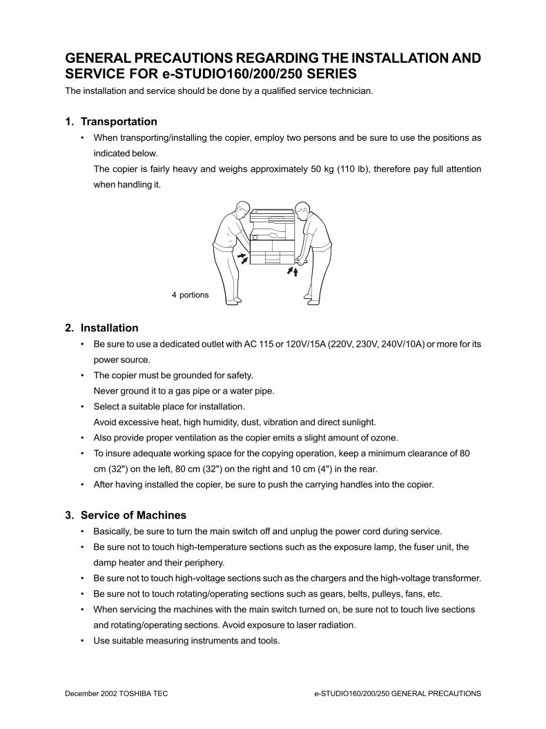
GENERAL PRECAUTIONS REGARDING THE INSTALLATION ANDSERVICE FOR e-STUDIO160/200/250 SERIESThe installation and service should be done by a qualified service technician.
1. Transportation
• When transporting/installing the copier, employ two persons and be sure to use the positions as
indicated below.
The copier is fairly heavy and weighs approximately 50 kg (110 lb), therefore pay full attention
when handling it.
2. Installation
• Be sure to use a dedicated outlet with AC 115 or 120V/15A (220V, 230V, 240V/10A) or more for its
power source.
• The copier must be grounded for safety.
Never ground it to a gas pipe or a water pipe.
• Select a suitable place for installation.
Avoid excessive heat, high humidity, dust, vibration and direct sunlight.
• Also provide proper ventilation as the copier emits a slight amount of ozone.
• To insure adequate working space for the copying operation, keep a minimum clearance of 80
cm (32") on the left, 80 cm (32") on the right and 10 cm (4") in the rear.
• After having installed the copier, be sure to push the carrying handles into the copier.
3. Service of Machines
• Basically, be sure to turn the main switch off and unplug the power cord during service.
• Be sure not to touch high-temperature sections such as the exposure lamp, the fuser unit, the
damp heater and their periphery.
• Be sure not to touch high-voltage sections such as the chargers and the high-voltage transformer.
• Be sure not to touch rotating/operating sections such as gears, belts, pulleys, fans, etc.
• When servicing the machines with the main switch turned on, be sure not to touch live sections
and rotating/operating sections. Avoid exposure to laser radiation.
• Use suitable measuring instruments and tools.
4 portions
e-STUDIO160/200/250 GENERAL PRECAUTIONS December 2002 TOSHIBA TEC
• Avoid exposure to laser radiation during servicing.
– Avoid direct exposure to beam.
– Do not insert tools, parts, etc. that are reflective into the path of the laser beam.
– Remove all watches, rings, bracelets, etc. that are reflective.
4. Main Service Parts for Safety
• The breaker, door switch, fuse, thermostat, thermistor, etc. are particularly important for safety.
Be sure to handle/install them properly.
5. Cautionary Labels
• During servicing, be sure to check the rating plate and the cautionary labels such as “Unplug the
power cord during service”, “Hot area”, “Laser warning label” etc. to see if there is any dirt on their
surface and whether they are properly stuck to the copier.
6. Disposition of Consumable Parts/Packing Materials
• Regarding the recovery and disposal of the copier, supplies, consumable parts and packingm a -
terials, it is recommended to follow the relevant local regulations or rules.
7. When parts are disassembled, reassembly is basically the reverse of disas-
sembly unless otherwise noted in this manual or other related documents. Be
careful not to reassemble small parts such as screws, washers, pins, E-rings,
toothed washers in the wrong places.
8. Basically, the machine should not be operated with any parts removed or dis-
assembled.
9. Precautions Against Static Electricity
• The PC board must be stored in an anti-electrostatic bag and handled carefully using a wristband,
because the ICs on it may become damaged due to static electricity.
Caution: Before using the wrist band, pull out the power cord plug of the copier and make
sure that there is no uninsulated charged objects in the vicinity.
Caution: Dispose of used batteries and RAM-ICs including lithium batteries according to the
manufacturer's instructions.
Attention: Se débarrasser de batteries et RAM-ICs usés y compris les batteries en lithium
selon les instructions du fabricant.
Vorsicht: Entsorgung des gebrauchten Batterien und RAM-ICs (inklusive der Lithium-Batterie)
nach Angaben des Herstellers.

1. SPECIFICATIONS • ACCESSORIES •OPTIONS • SUPPLIES ........................... 1-1
1.1 Specifications ............................................................................................ 1-1
1.2 Accessories .............................................................................................. 1-5
1.3 Options ..................................................................................................... 1-6
1.4 Replacement Units/Supplies ..................................................................... 1-6
1.5 System List ............................................................................................... 1-7
December 2002 TOSHIBA TEC 1 - 1 e-STUDIO160/200/250 SPECIFICATIONS
1. SPECIFICATIONS • ACCESSORIES • OPTIONS • SUPPLIES1.1 Specifications
• Copy process ................ Indirect electrophotographic process (dry)
• Type ............................... Desktop type (console type when the paper feed pedestal and Large
capacity feeder are installed)
• Original table ................. Fixed table (the left rear corner used for standard original placement)
• Acceptable originals ...... Type: sheet, book, and 3-dimensional object.
However, the automatic document feeder (option) only accepts sheets of
paper (Multi-sheet: 50 - 105 g/m2, or 13 - 29 lb/Single-sheet: 105 - 127
g/m2, or 29 - 34 lb.), excluding carbon paper, pasted sheets and stapled
sheets.
Max size: A3/LD
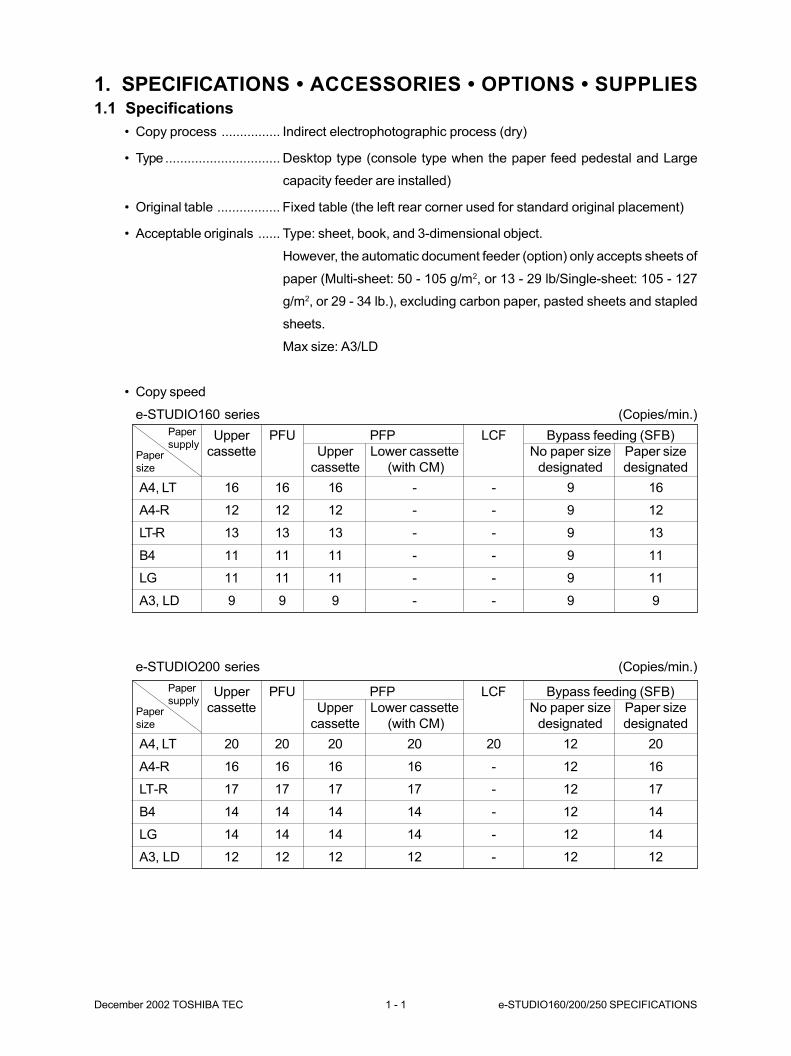
• Copy speed
e-STUDIO160 series (Copies/min.)
Upper PFU PFP LCF Bypass feeding (SFB)
cassette Upper Lower cassette No paper size Paper size
cassette (with CM) designated designated
A4, LT 20 20 20 20 20 12 20
A4-R 16 16 16 16 - 12 16
LT-R 17 17 17 17 - 12 17
B4 14 14 14 14 - 12 14
LG 14 14 14 14 - 12 14
A3, LD 12 12 12 12 - 12 12
Paper
size
Paper
supply
e-STUDIO200 series (Copies/min.)
Upper PFU PFP LCF Bypass feeding (SFB)
cassette Upper Lower cassette No paper size Paper size
cassette (with CM) designated designated
A4, LT 16 16 16 - - 9 16
A4-R 12 12 12 - - 9 12
LT-R 13 13 13 - - 9 13
B4 11 11 11 - - 9 11
LG 11 11 11 - - 9 11
A3, LD 9 9 9 - - 9 9
Paper
size
Paper
supply
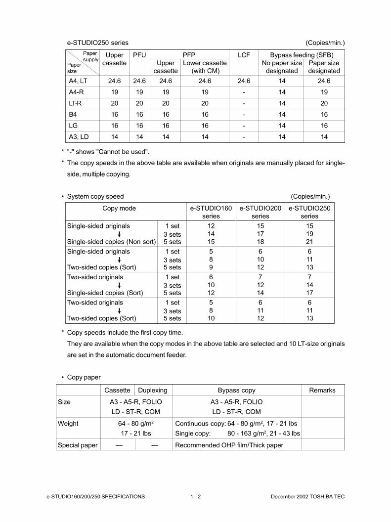
e-STUDIO160/200/250 SPECIFICATIONS 1 - 2 December 2002 TOSHIBA TEC
Cassette Duplexing Bypass copy Remarks
Size A3 - A5-R, FOLIO A3 - A5-R, FOLIO
LD - ST-R, COM LD - ST-R, COM
Weight 64 - 80 g/m2 Continuous copy: 64 - 80 g/m2, 17 - 21 lbs
17 - 21 lbs Single copy: 80 - 163 g/m2, 21 - 43 lbs
Special paper — — Recommended OHP film/Thick paper
* "-" shows "Cannot be used".
* The copy speeds in the above table are available when originals are manually placed for single-
side, multiple copying.
• System copy speed (Copies/min.)
* Copy speeds include the first copy time.
They are available when the copy modes in the above table are selected and 10 LT-size originals
are set in the automatic document feeder.
• Copy paper
Copy mode
Single-sided originals 1 set
3 setsSingle-sided copies (Non sort) 5 sets
Single-sided originals 1 set
3 setsTwo-sided copies (Sort) 5 sets
Two-sided originals 1 set
3 setsSingle-sided copies (Sort) 5 sets
Two-sided originals 1 set
3 setsTwo-sided copies (Sort) 5 sets
e-STUDIO250 series (Copies/min.)
Upper PFU PFP LCF Bypass feeding (SFB)
cassette Upper Lower cassette No paper size Paper size
cassette (with CM) designated designated
A4, LT 24.6 24.6 24.6 24.6 24.6 14 24.6
A4-R 19 19 19 19 - 14 19
LT-R 20 20 20 20 - 14 20
B4 16 16 16 16 - 14 16
LG 16 16 16 16 - 14 16
A3, LD 14 14 14 14 - 14 14
Paper
size
Paper
supply
e-STUDIO160
series
12
14
15
5
8
9
6
10
12
5
8
10
e-STUDIO200
series
15
17
18
6
10
12
7
12
14
6
11
12
e-STUDIO250
series
15
19
21
6
11
13
7
14
17
6
11
13

December 2002 TOSHIBA TEC 1 - 3 e-STUDIO160/200/250 SPECIFICATIONS
• First copy time ...................... e-STUDIO160 series: Less than 7.9 seconds (A4/LT, the Upper
cassette, 100%, original placed manually)
e-STUDIO200 series: Less than 7.0 seconds (A4/LT, the Upper
cassette, 100%, original placed manually)
e-STUDIO250 series: Less than 7.0 seconds (A4/LT, the Upper
cassette, 100%, original placed manually)
• Warming-up time .................. e-STUDIO160 series: Less than 60 seconds
e-STUDIO200 series: Less than 75 seconds
e-STUDIO250 series: Less than 75 seconds
• Multiple copying ................... Up to 999 copies; entry by numeric keys
• Reproduction ratio ................ Actual ratio: 100%
Zooming: 50 - 200% in increments of 1%
25 - 400% in increments of 1%
(for e-STUDIO200/250 series; with original cover)
• Resolution/Gradation ........... Read: 600 dpi x 600 dpi
Copy: 600 dpi x 600 dpi
Printer: 1200 dpi x 600 dpi
Fax: 16 dot/mm x 15.4 dot/mm (406 dpi x 392 dpi)
• Paper feeding ....................... Automatic feeding: Copier’s cassette 1 piece standard
e-STUDIO160 series: Expandable up to 3 pieces by installing
optional cassettes.
e-STUDIO200/250 series: Expandable up to 4 pieces by installing
optional cassettes.
PFU-optional (Stack height 60.5 mm, Equivalent to 550 sheets; 64 to
80 g/m2 (17 to 21 lb.))
PFP-optional (Stack height 60.5 mm, Equivalent to 550 sheets; 64 to
80 g/m2 (17 to 21 lb.))
LCF-optional (Stack height 165 mm, Equivalent to 1250 x 2 sheets;
64 to 80 g/m2 (17 to 21 lb.))
Bypass feeding (Stack height 16 mm, Equivalent to 100 sheets; 64 to
80 g/m2 (17 to 21 lb.))
• Capacity of originals of
automatic document feeder .. A4, A4-R, B5, B5-R, A5-R, LT, LT-R, ST-R: 50 sheets (with ADF)
B4, Folio, LG, Comp, A3, LD: 50 sheets (with ADF)
A4, A4-R, B5, B5-R, A5-R, LT, LT-R, ST-R: 100 sheets (with RADF)
B4, Folio, LG, Comp, A3, LD: 100 sheets (with RADF)
• Toner supplying .................... Automatic toner sensor detection
• Density control ...................... Automatic density mode and manual density mode selectable in 7
steps
e-STUDIO160/200/250 SPECIFICATIONS 1 - 4 December 2002 TOSHIBA TEC
e-STUDIO160 series e-STUDIO200/250 series
Standard 530 x 554 x 600 mm 530 x 554 x 600 mm
Standard + Original cover 530 x 554 x 643 mm 530 x 554 x 643 mm
Standard + ADF 530 x 554 x 731 mm 530 x 554 x 731 mm
Standard + RADF 545 x 599 x 772 mm 545 x 599 x 772 mm
Standard + ADU + RADF 607 x 599 x 772 mm 607 x 599 x 772 mm
Standard + Original cover + PFU 530 x 554 x 757 mm 530 x 554 x 757 mm
Standard + Original cover + PFU + PFP 530 x 554 x 1039 mm 530 x 554 x 1039 mm
Standard + Original cover + JSP 604 x 554 x 643 mm 604 x 554 x 643 mm
Standard + Original cover + SFB 801 x 554 x 643 mm 801 x 554 x 643 mm
Standard + Original cover + OCT 604 x 554 x 643 mm 604 x 554 x 643 mm
Standard + Original cover + Stapler 787 x 554 x 676 mm 787 x 554 x 676 mm
Standard + Original cover + Finisher ----- 957 x 554 x 643 mm
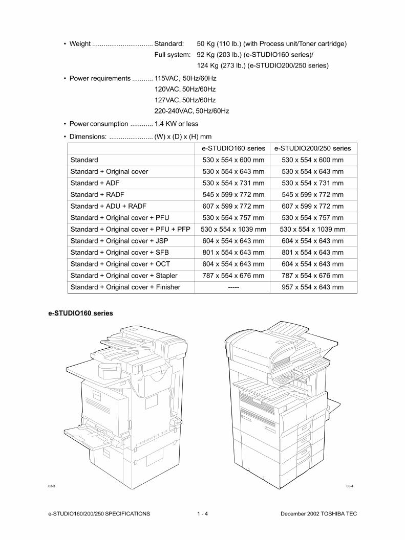
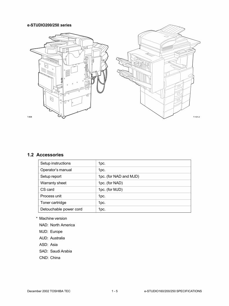
• Weight ................................ Standard: 50 Kg (110 lb.) (with Process unit/Toner cartridge)
Full system: 92 Kg (203 lb.) (e-STUDIO160 series)/
124 Kg (273 lb.) (e-STUDIO200/250 series)
• Power requirements ........... 115VAC, 50Hz/60Hz
120VAC, 50Hz/60Hz
127VAC, 50Hz/60Hz
220-240VAC, 50Hz/60Hz
• Power consumption ............ 1.4 KW or less
• Dimensions: ....................... (W) x (D) x (H) mm
03-3 03-4
e-STUDIO160 series
December 2002 TOSHIBA TEC 1 - 5 e-STUDIO160/200/250 SPECIFICATIONS
1.2 Accessories
* Machine version
NAD: North America
MJD: Europe
AUD: Australia
ASD: Asia
SAD: Saudi Arabia
CND: China
Setup instructions 1pc.
Operator’s manual 1pc.
Setup report 1pc. (for NAD and MJD)
Warranty sheet 1pc. (for NAD)
CS card 1pc. (for MJD)
Process unit 1pc.
Toner cartridge 1pc.
Detouchable power cord 1pc.
T-808
e-STUDIO200/250 series
T-101-2

e-STUDIO160/200/250 SPECIFICATIONS 1 - 6 December 2002 TOSHIBA TEC
Fuser unit FUSER-1600-120, FUSER-1600-240 (for e-STUDIO160 series)
FUSER-2500-120, FUSER-2500-240 (for e-STUDIO200/250 series)
Transfer charger unit MAIN-CH-1600
1.4 Replacement Units/Supplies
(1) Replacement units
(2) Process unit
Process unit PU-1610S, PU-1610ES, PU-1610DS, PU-1610DSN, PU-1610CS
1.3 Options
Original cover KA-1600PC, KA-1600PC-N
Paper feed pedestal-1 (PFP) KD-1009, KD-1009-N
Automatic duplexing unit-1(ADU) MD-0101, MD-0101-N
Automatic document feeder (ADF) MR-2012, MR-2012-N
Reverse automatic document feeder-1 (RADF) MR-3011
Paper feed unit (PFU) MY-1015, MY-1015-N
Cassette module (CM) MY-1017, MY-1017-N
(for e-STUDIO200/250 series)
Large capacity feeder (LCF) KD-1010, KD-1010-N
(for e-STUDIO200/250 series)
Paper feed controller (PFC) GH-1030, GH-1030-N
Job separator (JSP) MJ-5001, MJ-5001-N
Offset tray MJ-5002, MJ-5002-N
Stack feed bypass (SFB) MY-1016, MY-1016-N
Printer kit (Printer control) GA-1031
Memory kit GC-1050, GC-1050-N
Fax board kit GD-1061-EU, GD-1061-NA, GD-1061-AU,
GD-1061-SA, GD-1061C
Internet fax kit GD-1070
NIC kit (Network interface card) GF-1110
Staple with surface KK-1600
Finisher MJ-1011
(for e-STUDIO200/250 series)
Toner cartridge T-1600, T-1600E, T-1600D, T-1600C (for e-STUDIO160 series)
T-2500, T-2500E, T-2500D, T-2500C (for e-STUDIO200/250 series)
(3) Supplies
December 2002 TOSHIBA TEC 1 - 7 e-STUDIO160/200/250 SPECIFICATIONS
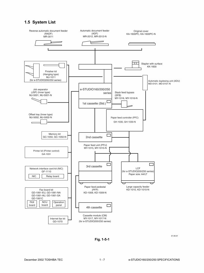
Reverse automatic document feeder(RADF)
MR-3011
Automatic document feeder(ADF)
MR-2012, MR-2012-N
Original coverKA-1600PC, KA-1600PC-N
Finisher kit(Hanging type)
MJ-1011(for e-STUDIO200/250 series)
Stack feed bypass(SFB)MY-1016, MY-1016-N
Automatic duplexing unit (ADU)MD-0101, MD-0101-N
Paper feed controller (PFC)
GH-1030, GH-1030-N
Paper feed unit (PFU)MY-1015, MY-1015-N
Paper feed pedestal(PFP)
KD-1009, KD-1009-N
Large capacity feederKD-1010, KD-1010-N
Cassette module (CM)MY-1017, MY-1017-N
(for e-STUDIO200/250 series)Internet fax kit
GD-1070
Fax board kitGD-1061-EU, GD-1061-NAGD-1061-AU, GD-1061-SAGD-1061C
FAXboard
NCUboard
Operationpanel
Network interface card kit (NIC)GF-1110
NIC Relay board
Printer kit (Printer control)GA-1031
Memory kitGC-1050, GC-1050-N
Offset tray (Inner type)MJ-5002, MJ-5002-N
Job separator(JSP) (Inner type)
MJ-5001, MJ-5001-N
Stapler with surfaceKK-1600
LCF(for e-STUDIO200/250 series)
Paper size: A4/LT
e-STUDIO160/200/250 series
1st cassette (Std.)
2nd cassette
4th cassette
3rd cassette
1.5 System List
Fig. 1-5-1
01-05-01
2. OUTLINE OF THE MACHINE .................. 2-1
2.1 Sectional View .......................................................................................... 2-1
2.2 Location of Electrical Parts ....................................................................... 2-5
2.3 Symbols and Functions of Various Devices .............................................. 2-13
2.4 Copy Paper Path ...................................................................................... 2-18
2.4.1 Normal.......................................................................................... 2-18
2.4.2 When the PFU, PFP, ADU, SFB and OCT are mounted .............. 2-18
2.4.3 When the PFU, PFP, CM, ADU, SFB and JSP are mounted ....... 2-19
2.4.4 When the PFU, LCF, ADU, SFB and Finisher are mounted ......... 2-19
2.5 System Block Diagrams ............................................................................ 2-20
2.6 Removal and Reinstallation of Covers and PC Boards............................. 2-21
2.6.1 Removal and reinstallation of covers ........................................... 2-21
2.6.2 Removal of PC boards ................................................................. 2-29
December 2002 TOSHIBA TEC 2 - 1 e-STUDIO160/200/250 OUTLINE OF THE MACHINE
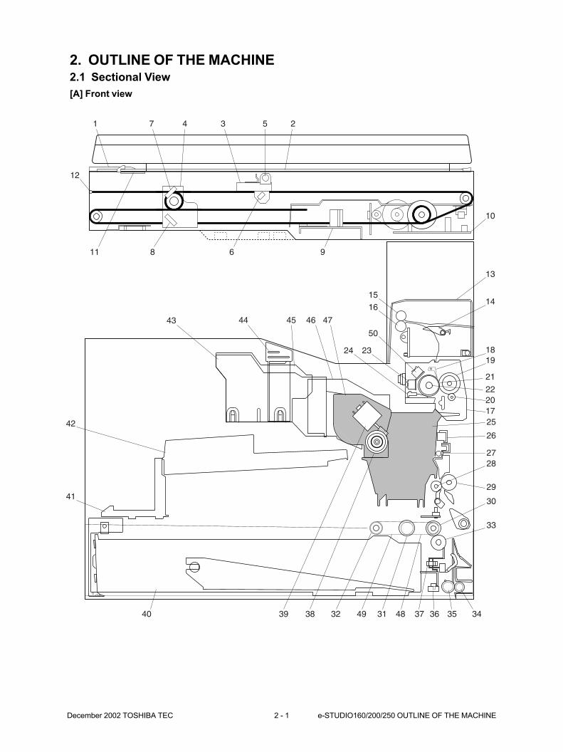
2. OUTLINE OF THE MACHINE2.1 Sectional View
[A] Front view
1
11 8 6 9
43 44 45 46 47
343536373149 483239 3840
7 3 5 2
10
13
14
1819
22
21
201725
26
2728
29
30
33
4
12
1516
24 23
50
41
42

e-STUDIO160/200/250 OUTLINE OF THE MACHINE 2 - 2 December 2002 TOSHIBA TEC
1 ADF glass
2 Original glass
3 Carriage 1
4 Carriage 2
5 Exposure lamp
6 Reflecting mirror 1
7 Reflecting mirror 2
8 Reflecting mirror 3
9 CCD unit
10 Scanner control PWA
11 Shading sheet
12 Wire F
13 Exit cover
14 Scraper
15 Exit pinch roller
16 Exit roller
17 Fuser unit
18 Separation claw
19 Pressure roller
20 Cleaning roller
21 Heat roller
22 Heater lamp
23 Heater thermostat 1
24 Heater thermistor 1/2
25 Process unit
26 Transfer charger
27 Transfer guide roller
28 Pinch roller
29 Registration roller
30 Feed roller
31 Pickup roller
32 Timing pulley
33 Separation roller
34 2nd pinch roller
35 2nd feed roller
36 Cassette slider
37 Cassette catch
38 Toner supply gear
39 Toner supply motor
40 Paper cassette (STD)
41 LSU stay
42 Laser scanner unit
43 Duct lower
44 Ozone filter cover/Ozone filter 1
45 Duct upper
46 Duct front
47 Toner cartridge
48 Timing belt 194
49 Timing belt 124
50 Heater thermostat 2

December 2002 TOSHIBA TEC 2 - 3 e-STUDIO160/200/250 OUTLINE OF THE MACHINE
[B] Rear view
11
12
24
2926
27
51
3036
4142
43
44
47 46
45
48
49
50
4039
35
34
323352
31
141516
25
38
37
13
1817 19 2021 22
7
6
23
28
8
9
10
1 2 3 4 5
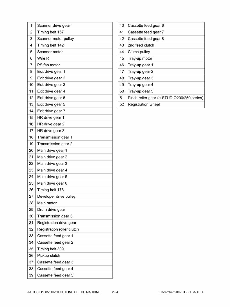
e-STUDIO160/200/250 OUTLINE OF THE MACHINE 2 - 4 December 2002 TOSHIBA TEC
40 Cassette feed gear 6
41 Cassette feed gear 7
42 Cassette feed gear 8
43 2nd feed clutch
44 Clutch pulley
45 Tray-up motor
46 Tray-up gear 1
47 Tray-up gear 2
48 Tray-up gear 3
49 Tray-up gear 4
50 Tray-up gear 5
51 Pinch roller gear (e-STUDIO200/250 series)
52 Registration wheel
1 Scanner drive gear
2 Timing belt 157
3 Scanner motor pulley
4 Timing belt 142
5 Scanner motor
6 Wire R
7 PS fan motor
8 Exit drive gear 1
9 Exit drive gear 2
10 Exit drive gear 3
11 Exit drive gear 4
12 Exit drive gear 6
13 Exit drive gear 5
14 Exit drive gear 7
15 HR drive gear 1
16 HR drive gear 2
17 HR drive gear 3
18 Transmission gear 1
19 Transmission gear 2
20 Main drive gear 1
21 Main drive gear 2
22 Main drive gear 3
23 Main drive gear 4
24 Main drive gear 5
25 Main drive gear 6
26 Timing belt 176
27 Developer drive pulley
28 Main motor
29 Drum drive gear
30 Transmission gear 3
31 Registration drive gear
32 Registration roller clutch
33 Cassette feed gear 1
34 Cassette feed gear 2
35 Timing belt 309
36 Pickup clutch
37 Cassette feed gear 3
38 Cassette feed gear 4
39 Cassette feed gear 5
December 2002 TOSHIBA TEC 2 - 5 e-STUDIO160/200/250 OUTLINE OF THE MACHINE
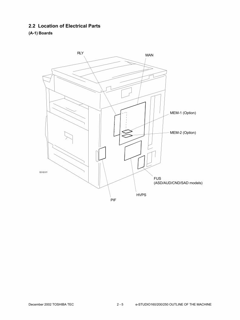
2.2 Location of Electrical Parts
(A-1) Boards
RLYMAN
MEM-1 (Option)
MEM-2 (Option)
FUS
(ASD/AUD/CND/SAD models)
HVPS
PIF
02-02-01
e-STUDIO160/200/250 OUTLINE OF THE MACHINE 2 - 6 December 2002 TOSHIBA TEC
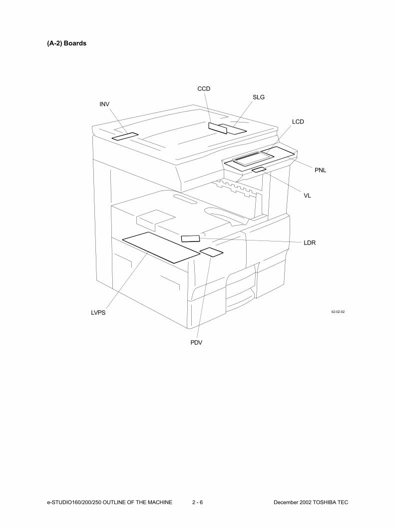
(A-2) Boards
INV
CCD
SLG
LCD
PNL
VL
LDR
PDV
LVPS 02-02-02
December 2002 TOSHIBA TEC 2 - 7 e-STUDIO160/200/250 OUTLINE OF THE MACHINE
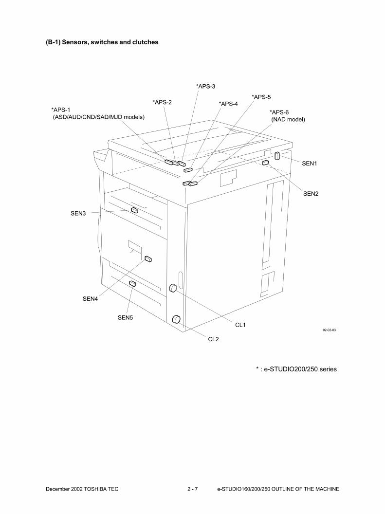
(B-1) Sensors, switches and clutches
*APS-1
(ASD/AUD/CND/SAD/MJD models)
*APS-2
*APS-3
*APS-4*APS-5
*APS-6
(NAD model)
SEN1
SEN2
CL1
CL2
SEN5
SEN4
SEN3
* : e-STUDIO200/250 series
02-02-03
e-STUDIO160/200/250 OUTLINE OF THE MACHINE 2 - 8 December 2002 TOSHIBA TEC
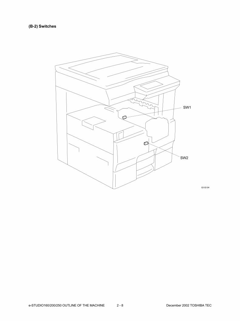
(B-2) Switches
SW2
SW1
02-02-04

December 2002 TOSHIBA TEC 2 - 9 e-STUDIO160/200/250 OUTLINE OF THE MACHINE
(B-3) Sensors, switches and clutches
SEN6
SEN7
CL3
SW3
02-02-05
e-STUDIO160/200/250 OUTLINE OF THE MACHINE 2 - 10 December 2002 TOSHIBA TEC
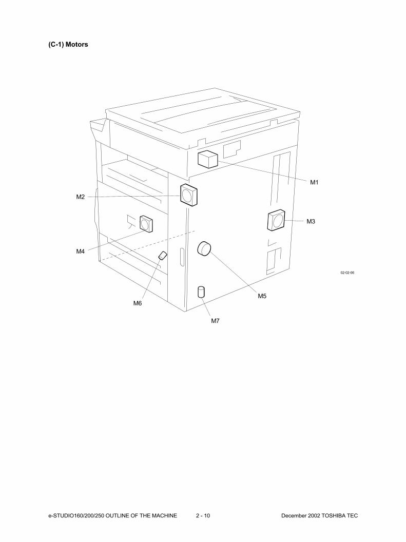
(C-1) Motors
M1
M3
M5
M7
M6
M4
M2
02-02-06

December 2002 TOSHIBA TEC 2 - 11 e-STUDIO160/200/250 OUTLINE OF THE MACHINE
(D-1) Thermostat, thermistors and heaters
THM1
HL2
(ASD/AUD/CND/MJD models)
THM2
THM3
HL3
(ASD/AUD/CND/MJD models)
HL1
(NAD/SAD models)
02-02-10
THM6
e-STUDIO160/200/250 OUTLINE OF THE MACHINE 2 - 12 December 2002 TOSHIBA TEC
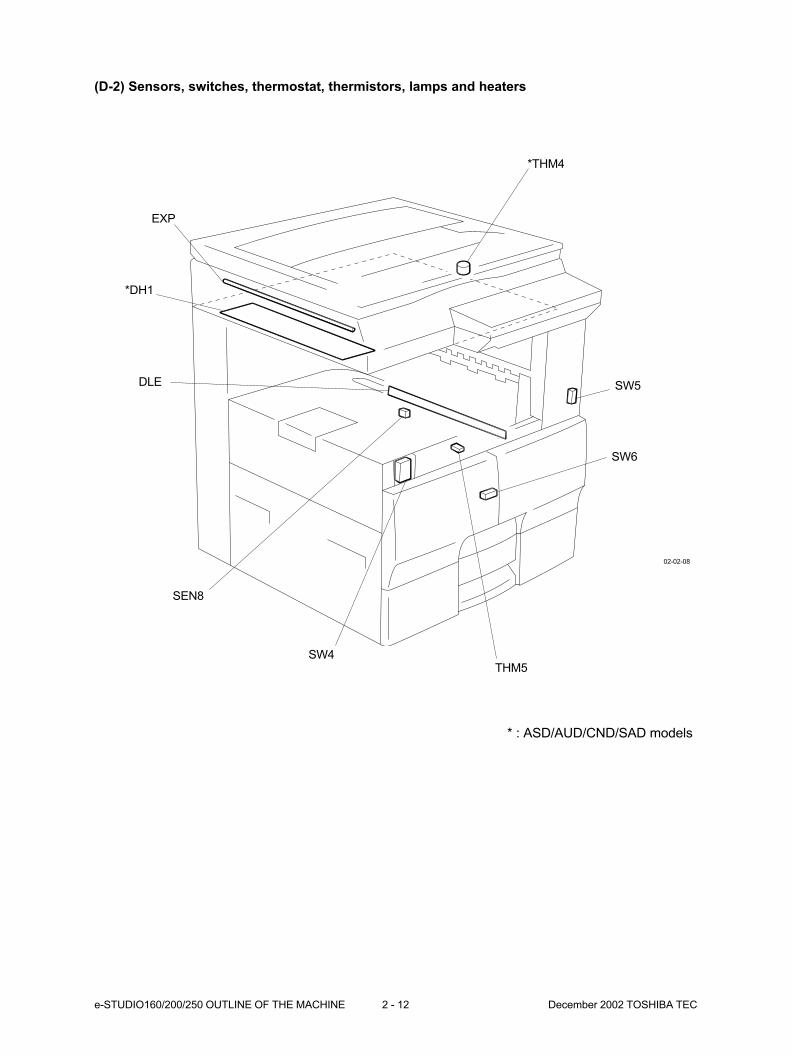
(D-2) Sensors, switches, thermostat, thermistors, lamps and heaters
*THM4
EXP
THM5
DLE
SEN8
SW4
SW5
SW6
02-02-08
* : ASD/AUD/CND/SAD models
*DH1
December 2002 TOSHIBA TEC 2 - 13 e-STUDIO160/200/250 OUTLINE OF THE MACHINE
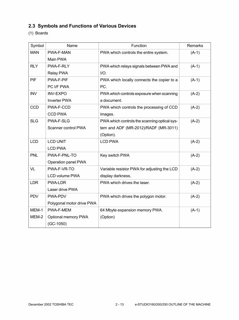
2.3 Symbols and Functions of Various Devices
(1) Boards
Remarks
(A-1)
(A-1)
(A-1)
(A-2)
(A-2)
(A-2)
(A-2)
(A-2)
(A-2)
(A-2)
(A-2)
(A-1)
Function
PWA which controls the entire system.
PWA which relays signals between PWA and
I/O.
PWA which locally connects the copier to a
PC.
PWA which controls exposure when scanning
a document.
PWA which controls the processing of CCD
images.
PWA which controls the scanning optical sys-
tem and ADF (MR-2012)/RADF (MR-3011)
(Option).
LCD PWA
Key switch PWA
Variable resistor PWA for adjusting the LCD
display darkness.
PWA which drives the laser.
PWA which drives the polygon motor.
64 Mbyte expansion memory PWA.
(Option)
Symbol
MAN
RLY
PIF
INV
CCD
SLG
LCD
PNL
VL
LDR
PDV
MEM-1
MEM-2
Name
PWA-F-MAN
Main PWA
PWA-F-RLY
Relay PWA
PWA-F-PIF
PC I/F PWA
INV-EXPO
Inverter PWA
PWA-F-CCD
CCD PWA
PWA-F-SLG
Scanner control PWA
LCD UNIT
LCD PWA
PWA-F-PNL-TO
Operation panel PWA
PWA-F-VR-TO
LCD volume PWA
PWA-LDR
Laser drive PWA
PWA-PDV
Polygonal motor drive PWA
PWA-F-MEM
Optional memory PWA
(GC-1050)
e-STUDIO160/200/250 OUTLINE OF THE MACHINE 2 - 14 December 2002 TOSHIBA TEC
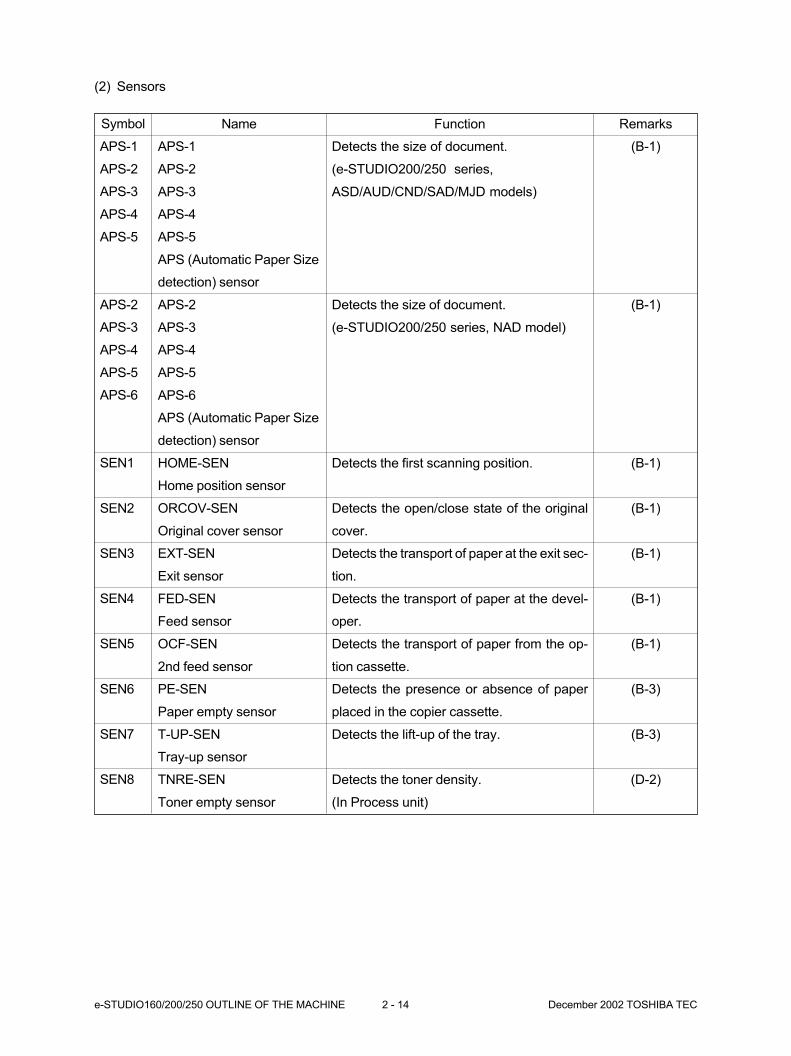
(2) Sensors
Remarks
(B-1)
(B-1)
(B-1)
(B-1)
(B-1)
(B-1)
(B-1)
(B-3)
(B-3)
(D-2)
Function
Detects the size of document.
(e-STUDIO200/250 series,
ASD/AUD/CND/SAD/MJD models)
Detects the size of document.
(e-STUDIO200/250 series, NAD model)
Detects the first scanning position.
Detects the open/close state of the original
cover.
Detects the transport of paper at the exit sec-
tion.
Detects the transport of paper at the devel-
oper.
Detects the transport of paper from the op-
tion cassette.
Detects the presence or absence of paper
placed in the copier cassette.
Detects the lift-up of the tray.
Detects the toner density.
(In Process unit)
Symbol
APS-1
APS-2
APS-3
APS-4
APS-5
APS-2
APS-3
APS-4
APS-5
APS-6
SEN1
SEN2
SEN3
SEN4
SEN5
SEN6
SEN7
SEN8
Name
APS-1
APS-2
APS-3
APS-4
APS-5
APS (Automatic Paper Size
detection) sensor
APS-2
APS-3
APS-4
APS-5
APS-6
APS (Automatic Paper Size
detection) sensor
HOME-SEN
Home position sensor
ORCOV-SEN
Original cover sensor
EXT-SEN
Exit sensor
FED-SEN
Feed sensor
OCF-SEN
2nd feed sensor
PE-SEN
Paper empty sensor
T-UP-SEN
Tray-up sensor
TNRE-SEN
Toner empty sensor
December 2002 TOSHIBA TEC 2 - 15 e-STUDIO160/200/250 OUTLINE OF THE MACHINE
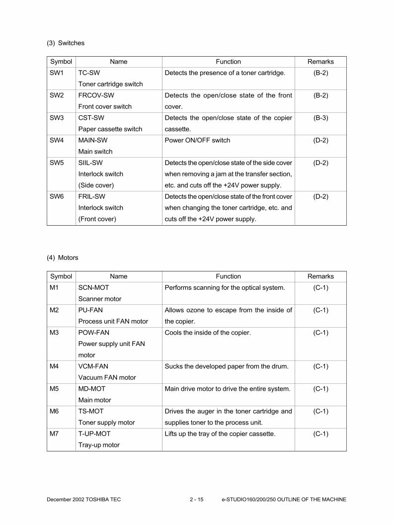
(3) Switches
Remarks
(B-2)
(B-2)
(B-3)
(D-2)
(D-2)
(D-2)
Function
Detects the presence of a toner cartridge.
Detects the open/close state of the front
cover.
Detects the open/close state of the copier
cassette.
Power ON/OFF switch
Detects the open/close state of the side cover
when removing a jam at the transfer section,
etc. and cuts off the +24V power supply.
Detects the open/close state of the front cover
when changing the toner cartridge, etc. and
cuts off the +24V power supply.
Symbol
SW1
SW2
SW3
SW4
SW5
SW6
Name
TC-SW
Toner cartridge switch
FRCOV-SW
Front cover switch
CST-SW
Paper cassette switch
MAIN-SW
Main switch
SIIL-SW
Interlock switch
(Side cover)
FRIL-SW
Interlock switch
(Front cover)
(4) Motors
Remarks
(C-1)
(C-1)
(C-1)
(C-1)
(C-1)
(C-1)
(C-1)
Function
Performs scanning for the optical system.
Allows ozone to escape from the inside of
the copier.
Cools the inside of the copier.
Sucks the developed paper from the drum.
Main drive motor to drive the entire system.
Drives the auger in the toner cartridge and
supplies toner to the process unit.
Lifts up the tray of the copier cassette.
Symbol
M1
M2
M3
M4
M5
M6
M7
Name
SCN-MOT
Scanner motor
PU-FAN
Process unit FAN motor
POW-FAN
Power supply unit FAN
motor
VCM-FAN
Vacuum FAN motor
MD-MOT
Main motor
TS-MOT
Toner supply motor
T-UP-MOT
Tray-up motor
e-STUDIO160/200/250 OUTLINE OF THE MACHINE 2 - 16 December 2002 TOSHIBA TEC
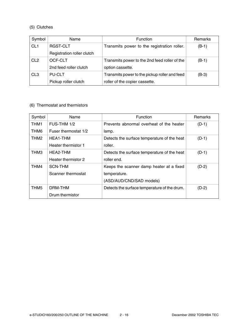
(5) Clutches
Remarks
(B-1)
(B-1)
(B-3)
Function
Transmits power to the registration roller.
Transmits power to the 2nd feed roller of the
option cassette.
Transmits power to the pickup roller and feed
roller of the copier cassette.
Symbol
CL1
CL2
CL3
Name
RGST-CLT
Registration roller clutch
OCF-CLT
2nd feed roller clutch
PU-CLT
Pickup roller clutch
(6) Thermostat and thermistors
Remarks
(D-1)
(D-1)
(D-1)
(D-2)
(D-2)
Function
Prevents abnormal overheat of the heater
lamp.
Detects the surface temperature of the heat
roller.
Detects the surface temperature of the heat
roller end.
Keeps the scanner damp heater at a fixed
temperature.
(ASD/AUD/CND/SAD models)
Detects the surface temperature of the drum.
Symbol
THM1
THM6
THM2
THM3
THM4
THM5
Name
FUS-THM 1/2
Fuser thermostat 1/2
HEA1-THM
Heater thermistor 1
HEA2-THM
Heater thermistor 2
SCN-THM
Scanner thermostat
DRM-THM
Drum thermistor

December 2002 TOSHIBA TEC 2 - 17 e-STUDIO160/200/250 OUTLINE OF THE MACHINE
(7) Heaters and lamps
(8) Transformers
Remarks
(A-1)
Function
PWA which generates high voltage power.
Symbol
HVPS
Name
PS-HVPS
High voltage power supply
unit
(9) Others
Remarks
(D-2)
(D-1)
(D-1)
(D-1)
(D-2)
(D-2)
Function
A light source lamp for document scanning.
Fixes toner to the paper.
(NAD/SAD models)
Fixes toner to the paper.
(ASD/AUD/CND/MJD models)
Dehumidifies the inside of the scanner.
(SAD model)
Dehumidifies the inside of the scanner.
(ASD/AUD/CND models)
Removes residual charge on the drum
surface. (In Process unit)
Symbol
EXP
HL1
HL2
HL3
DH1
DLE
Name
EXPO-LAMP
Exposure lamp
U900-HL
Heater lamp U900
E400-HL
Heater lamp E400
E500-HL
Heater lamp E500
SCN-DH-115
Scanner dump heater
SCN-DH-230
Scanner dump heater
PWA-F-DLE
Discharge LED PWA
Remarks
(A-2)
(A-2)
(A-1)
Function
PWA which generates DC power.
(NAD/SAD models)
PWA which generates DC power.
(ASD/AUD/CND/MJD models)
PWA which relays AC power to each damp
heater.
(ASD/AUD/CND/SAD models)
Symbol
LVPS
FUS
Name
PS-LVPS-US
Switching power supply unit
PS-LVPS-EU
Switching power supply unit
PWA-F-FUS
Fuser relay PWA
e-STUDIO160/200/250 OUTLINE OF THE MACHINE 2 - 18 December 2002 TOSHIBA TEC
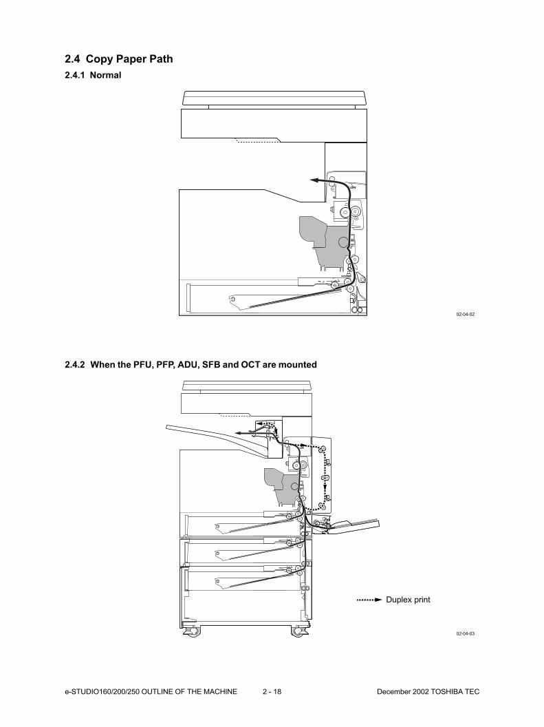
2.4 Copy Paper Path
2.4.1 Normal
2.4.2 When the PFU, PFP, ADU, SFB and OCT are mounted
02-04-02
02-04-03
Duplex print

December 2002 TOSHIBA TEC 2 - 19 e-STUDIO160/200/250 OUTLINE OF THE MACHINE
2.4.3 When the PFU, PFP, CM, ADU, SFB and JSP are mounted
2.4.4 When the PFU, LCF, ADU, SFB and Finisher are mounted
02-04-04
02-04-05
Duplex print
Duplex print
e-STUDIO160/200/250 OUTLINE OF THE MACHINE 2 - 20 December 2002 TOSHIBA TEC
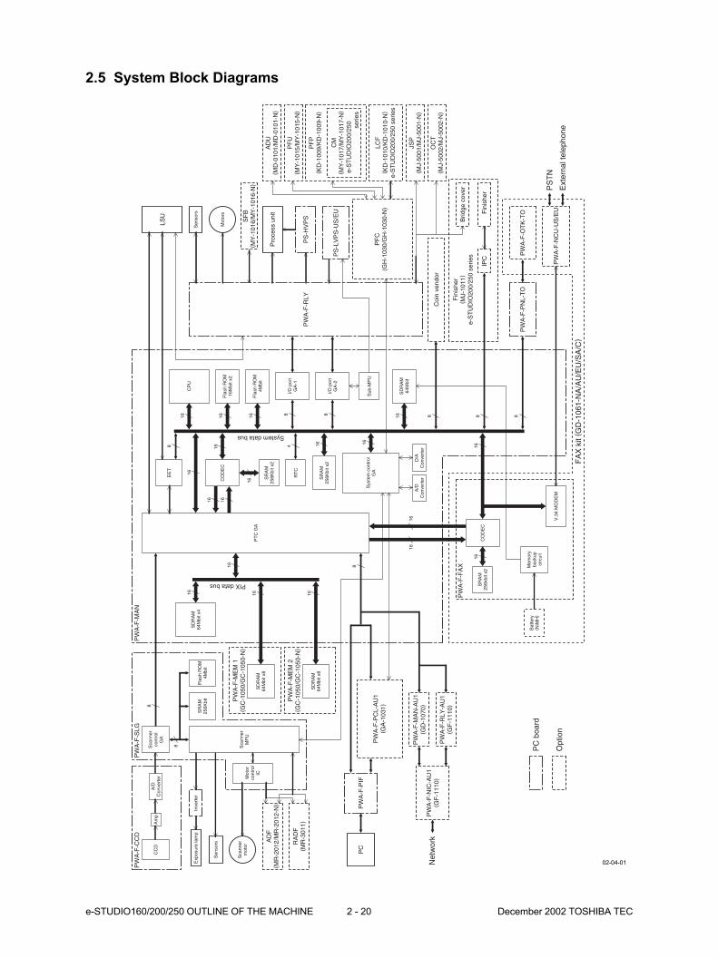
2.5 System Block Diagrams
PC
boa
rd
SF
B( M
Y-1
016/
MY
-101
6-N
)
PW
A-F
-PC
L-A
U1
( GA
-103
1)
PW
A-F
-NIC
-AU
1( G
F-1
110)
Net
wor
k
PW
A-F
-MA
N-A
U1
( GD
-107
0)
PW
A-F
-RLY
-AU
1( G
F-1
110)
PW
A-F
-FA
X
CC
DA
/DC
onve
rter
A/D
Con
vert
erD
/AC
onve
rter
Sca
nner
cont
rol
GA
PT
C G
A
Sys
tem
con
trol
G
A
I/O p
ort
GA
-1
I/O p
ort
GA
-2
Sub
-MP
U
Fla
sh R
OM
4Mbi
t
CO
DE
C
SD
RA
M64
Mbi
t x4
SR
AM
256K
bit
Sca
nner
MP
U
Am
p
Exp
osur
e la
mp
Inve
rter
Sen
sors
Mot
orco
ntro
lIC
AD
F( M
R-2
012/
MR
-201
2-N
)
RA
DF
( MR
-301
1)
8
8
16
16EE
TLS
U8
8 8 88
4
16
Sca
nner
mot
or
Sen
sors
Mot
ors
16
Fla
sh R
OM
16M
bit x
2
CP
U16 16
SR
AM
256K
bit x
2
16
Fla
sh R
OM
4Mbi
t
16
SD
RA
M64
Mbi
t
RT
C
16
16
SD
RA
M64
Mbi
t x8
SD
RA
M64
Mbi
t x8
PW
A-F
-ME
M 1
( GC
-105
0/G
C-1
050-
N)
System data bus
PIX data bus
16
16 1616
16 16
PW
A-F
-ME
M 2
( GC
-105
0/G
C-1
050-
N)
PW
A-F
-SLG
PW
A-F
-MA
NP
WA
-F-C
CD
SR
AM
256K
bit x
2
CO
DE
C
Mem
ory
back
up
circ
uit
V.3
4 M
OD
EM
1616
SR
AM
256k
bit x
2
16
PW
A-F
-PN
L-T
OP
WA
-F-O
TK
-TO
PW
A-F
-NC
U-U
S/E
U
PW
A-F
-RLY
PS
-LV
PS
-US
/EU
PS
-HV
PS
Pro
cess
uni
t Fin
ishe
r
AD
U( M
D-0
101/
MD
-010
1-N
)
PF
U( M
Y-1
015/
MY
-101
5-N
)
JSP
( MJ-
5001
/MJ-
5001
-N)
OC
T( M
J-50
02/M
J-50
02-N
)
Fin
ishe
r( M
J-10
11)
e-S
TU
DIO
200/
250
serie
s
PF
P( K
D-1
009/
KD
-100
9-N
)
LCF
( KD
-101
0/K
D-1
010-
N)
e-S
TU
DIO
200/
250
serie
s
CM
( MY
-101
7/M
Y-1
017-
N)
e-S
TU
DIO
200/
250
ser
ies
Brid
ge c
over
IPC
8
Coi
n ve
ndor
PW
A-F
-PIF
PS
TN
Ext
erna
l tel
epho
neO
ptio
n
PC
8
Bat
tery
( N
iMH
)
FA
X k
it ( G
D-1
061-
NA
/AU
/EU
/SA
/C)
PF
C(G
H-1
030/
GH
-103
0-N
)
02-04-01
December 2002 TOSHIBA TEC 2 - 21 e-STUDIO160/200/250 OUTLINE OF THE MACHINE
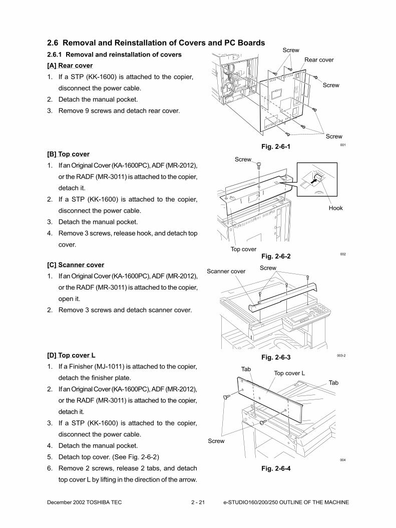
2.6 Removal and Reinstallation of Covers and PC Boards
2.6.1 Removal and reinstallation of covers
Fig. 2-6-1[B] Top cover
1. If an Original Cover (KA-1600PC), ADF (MR-2012),
or the RADF (MR-3011) is attached to the copier,
detach it.
2. If a STP (KK-1600) is attached to the copier,
disconnect the power cable.
3. Detach the manual pocket.
4. Remove 3 screws, release hook, and detach top
cover.
Fig. 2-6-2
Rear cover
Screw
Screw
Hook
Top cover
001
Screw
002
[C] Scanner cover
1. If an Original Cover (KA-1600PC), ADF (MR-2012),
or the RADF (MR-3011) is attached to the copier,
open it.
2. Remove 3 screws and detach scanner cover.
[A] Rear cover
1. If a STP (KK-1600) is attached to the copier,
disconnect the power cable.
2. Detach the manual pocket.
3. Remove 9 screws and detach rear cover.
Screw
Fig. 2-6-3
ScrewScanner cover
003-2[D] Top cover L
1. If a Finisher (MJ-1011) is attached to the copier,
detach the finisher plate.
2. If an Original Cover (KA-1600PC), ADF (MR-2012),
or the RADF (MR-3011) is attached to the copier,
detach it.
3. If a STP (KK-1600) is attached to the copier,
disconnect the power cable.
4. Detach the manual pocket.
5. Detach top cover. (See Fig. 2-6-2)
6. Remove 2 screws, release 2 tabs, and detach
top cover L by lifting in the direction of the arrow.
Fig. 2-6-4
Screw
Tab
TabTop cover L
004
e-STUDIO160/200/250 OUTLINE OF THE MACHINE 2 - 22 December 2002 TOSHIBA TEC
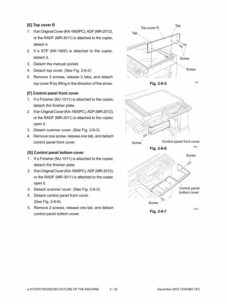
[E] Top cover R
1. If an Original Cover (KA-1600PC), ADF (MR-2012),
or the RADF (MR-3011) is attached to the copier,
detach it.
2. If a STP (KK-1600) is attached to the copier,
detach it.
3. Detach the manual pocket.
4. Detach top cover. (See Fig. 2-6-2)
5. Remove 3 screws, release 2 tabs, and detach
top cover R by lifting in the direction of the arrow. Fig. 2-6-5
Tab
Top cover RTab
Screw
Screw
005
[F] Control panel front cover
1. If a Finisher (MJ-1011) is attached to the copier,
detach the finisher plate.
2. If an Original Cover (KA-1600PC), ADF (MR-2012),
or the RADF (MR-3011) is attached to the copier,
open it.
3. Detach scanner cover. (See Fig. 2-6-3)
4. Remove one screw, release one tab, and detach
control panel front cover. Screw Control panel front cover
006-1
[G] Control panel bottom cover
1. If a Finisher (MJ-1011) is attached to the copier,
detach the finisher plate.
2. If an Original Cover (KA-1600PC), ADF (MR-2012),
or the RADF (MR-3011) is attached to the copier,
open it.
3. Detach scanner cover. (See Fig. 2-6-3)
4. Detach control panel front cover.
(See Fig. 2-6-6)
5. Remove 2 screws, release one tab, and detach
control panel bottom cover.
Screw
Control panel
bottom cover
Screw
006-2
Fig. 2-6-6
Fig. 2-6-7
December 2002 TOSHIBA TEC 2 - 23 e-STUDIO160/200/250 OUTLINE OF THE MACHINE
Control panel
Screw
Control panel harness
Ground wire
Screw
007
Screw
Clamp
Core
dropping.
Fig. 2-6-8
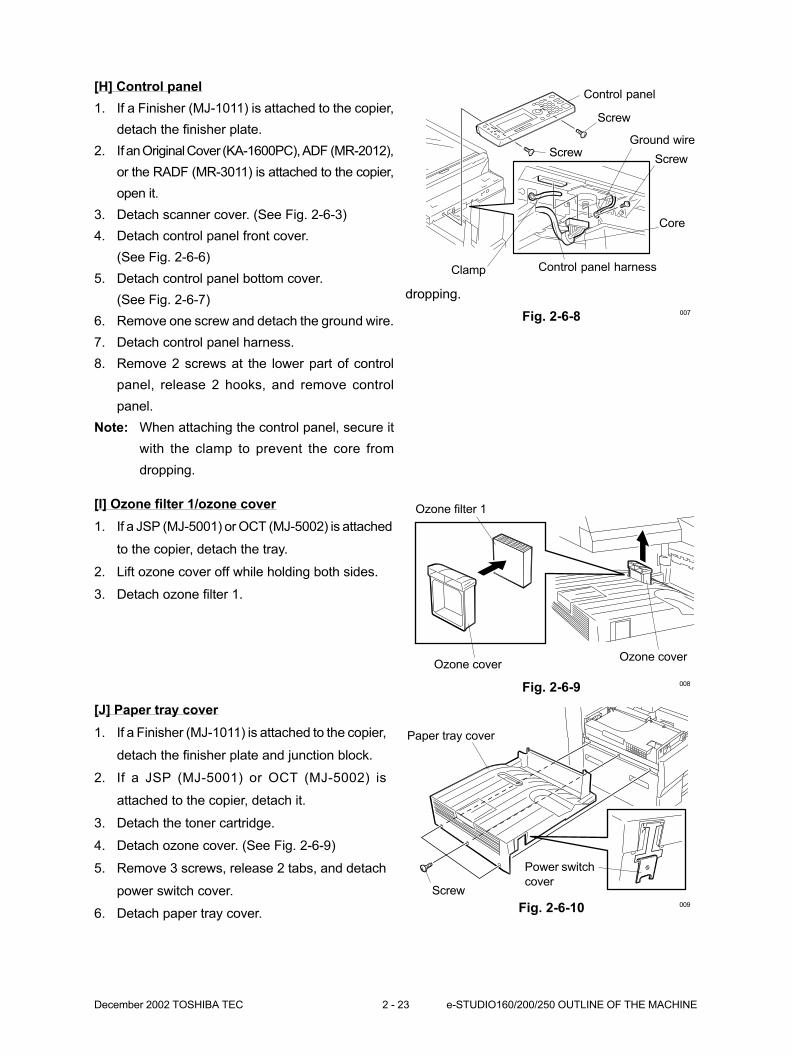
[J] Paper tray cover
1. If a Finisher (MJ-1011) is attached to the copier,
detach the finisher plate and junction block.
2. If a JSP (MJ-5001) or OCT (MJ-5002) is
attached to the copier, detach it.
3. Detach the toner cartridge.
4. Detach ozone cover. (See Fig. 2-6-9)
5. Remove 3 screws, release 2 tabs, and detach
power switch cover.
6. Detach paper tray cover.
[I] Ozone filter 1/ozone cover
1. If a JSP (MJ-5001) or OCT (MJ-5002) is attached
to the copier, detach the tray.
2. Lift ozone cover off while holding both sides.
3. Detach ozone filter 1.
Fig. 2-6-9
Fig. 2-6-10
Ozone cover
Ozone filter 1
Ozone cover
Paper tray cover
Screw
Power switch
cover
008
009
[H] Control panel
1. If a Finisher (MJ-1011) is attached to the copier,
detach the finisher plate.
2. If an Original Cover (KA-1600PC), ADF (MR-2012),
or the RADF (MR-3011) is attached to the copier,
open it.
3. Detach scanner cover. (See Fig. 2-6-3)
4. Detach control panel front cover.
(See Fig. 2-6-6)
5. Detach control panel bottom cover.
(See Fig. 2-6-7)
6. Remove one screw and detach the ground wire.
7. Detach control panel harness.
8. Remove 2 screws at the lower part of control
panel, release 2 hooks, and remove control
panel.
Note: When attaching the control panel, secure it
with the clamp to prevent the core from
dropping.
e-STUDIO160/200/250 OUTLINE OF THE MACHINE 2 - 24 December 2002 TOSHIBA TEC
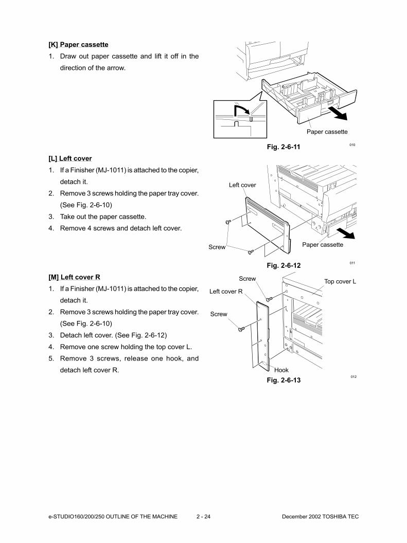
[K] Paper cassette
1. Draw out paper cassette and lift it off in the
direction of the arrow.
Fig. 2-6-11
[M] Left cover R
1. If a Finisher (MJ-1011) is attached to the copier,
detach it.
2. Remove 3 screws holding the paper tray cover.
(See Fig. 2-6-10)
3. Detach left cover. (See Fig. 2-6-12)
4. Remove one screw holding the top cover L.
5. Remove 3 screws, release one hook, and
detach left cover R.
Fig. 2-6-13
[L] Left cover
1. If a Finisher (MJ-1011) is attached to the copier,
detach it.
2. Remove 3 screws holding the paper tray cover.
(See Fig. 2-6-10)
3. Take out the paper cassette.
4. Remove 4 screws and detach left cover.
Fig. 2-6-12
Paper cassette
Left cover
Screw
Left cover R
Screw
010
011
012
Paper cassette
Screw Top cover L
Hook

December 2002 TOSHIBA TEC 2 - 25 e-STUDIO160/200/250 OUTLINE OF THE MACHINE
Fig.2-6-14
Screw
Screw
Upper right cover R
Lower right cover RSide cover
013-3
[N] Upper right cover R/Lower right cover R
In case that an ADU and SFB are not attached
or a SFB is attached.
1. Open side cover.
2. Remove 2 screws and detach upper right cover
R.
3. If a SFB (MY-1016) is attached to the copier,
detach it.
4. Remove 2 screws and detach lower right cover
R.
In case that an ADU is attached or an ADU
and SFB are attached.
1. Open an ADU (MD-0101) and release the wire.
2. Open side cover.
3. Remove 2 screws and detach upper right cover
R.
4. Detach an ADU (MD-0101) from the copier.
5. If a SFB (MY-1016) is attached to the copier,
detach it.
6. Remove 2 screws and detach lower right cover
R.
Fig. 2-6-15
4. Remove 2 screws securing stopper and guide
pin, then detach paper guide B, spring and side
cover assembly.
Fig. 2-6-16
Side cover
Clamp
Connector
Guide pin
Paper guide B Guide pin
Screw
Stopper
Side cover assembly
ScrewStopper
014
015
Spring
[O] Side cover assembly
1. Open ADU (MD-0101) if it is attached.
2. Detach upper right cover R. (See Fig.2-6-14)
3. Detach one connector and release the clamp.
e-STUDIO160/200/250 OUTLINE OF THE MACHINE 2 - 26 December 2002 TOSHIBA TEC
Fig. 2-6-18
Fig. 2-6-19
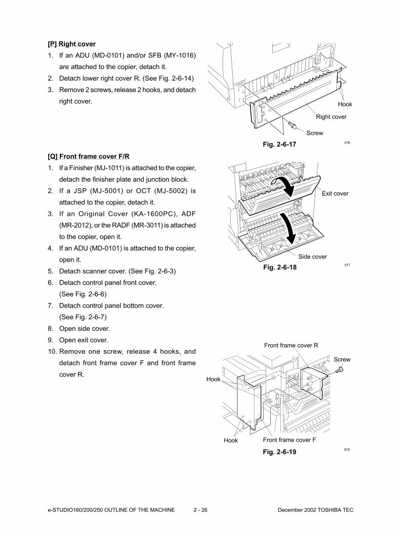
[P] Right cover
1. If an ADU (MD-0101) and/or SFB (MY-1016)
are attached to the copier, detach it.
2. Detach lower right cover R. (See Fig. 2-6-14)
3. Remove 2 screws, release 2 hooks, and detach
right cover.
Fig. 2-6-17
Hook
Right cover
Screw
Exit cover
Side cover
Front frame cover R
Hook
Hook Front frame cover F
016
017
018
Screw
[Q] Front frame cover F/R
1. If a Finisher (MJ-1011) is attached to the copier,
detach the finisher plate and junction block.
2. If a JSP (MJ-5001) or OCT (MJ-5002) is
attached to the copier, detach it.
3. If an Original Cover (KA-1600PC), ADF
(MR-2012), or the RADF (MR-3011) is attached
to the copier, open it.
4. If an ADU (MD-0101) is attached to the copier,
open it.
5. Detach scanner cover. (See Fig. 2-6-3)
6. Detach control panel front cover.
(See Fig. 2-6-6)
7. Detach control panel bottom cover.
(See Fig. 2-6-7)
8. Open side cover.
9. Open exit cover.
10. Remove one screw, release 4 hooks, and
detach front frame cover F and front frame
cover R.
December 2002 TOSHIBA TEC 2 - 27 e-STUDIO160/200/250 OUTLINE OF THE MACHINE
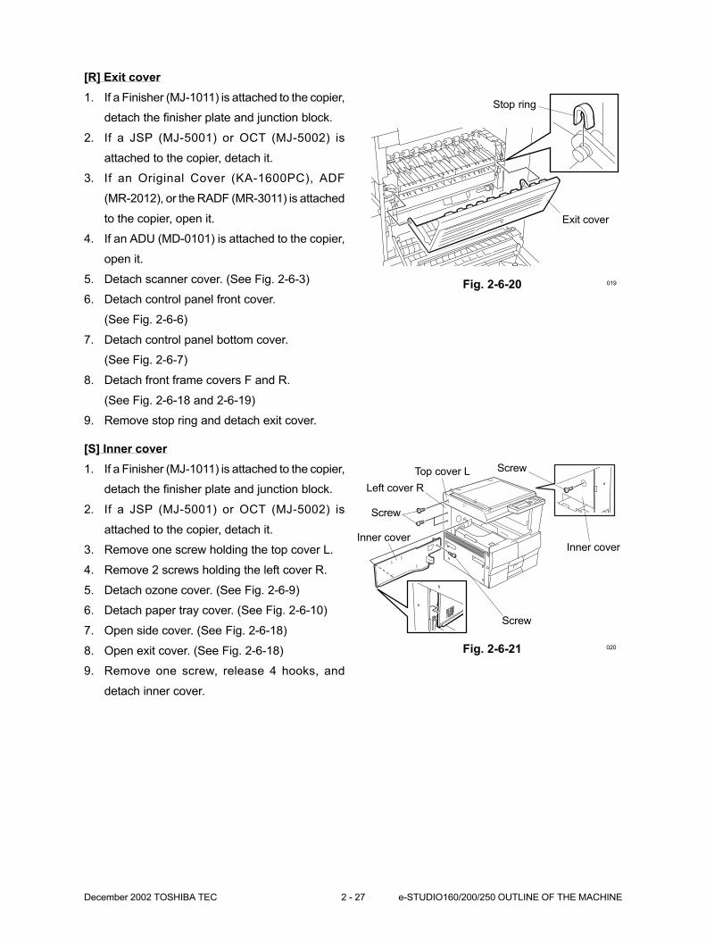
Fig. 2-6-20
Stop ring
Exit cover
019
[R] Exit cover
1. If a Finisher (MJ-1011) is attached to the copier,
detach the finisher plate and junction block.
2. If a JSP (MJ-5001) or OCT (MJ-5002) is
attached to the copier, detach it.
3. If an Original Cover (KA-1600PC), ADF
(MR-2012), or the RADF (MR-3011) is attached
to the copier, open it.
4. If an ADU (MD-0101) is attached to the copier,
open it.
5. Detach scanner cover. (See Fig. 2-6-3)
6. Detach control panel front cover.
(See Fig. 2-6-6)
7. Detach control panel bottom cover.
(See Fig. 2-6-7)
8. Detach front frame covers F and R.
(See Fig. 2-6-18 and 2-6-19)
9. Remove stop ring and detach exit cover.
[S] Inner cover
1. If a Finisher (MJ-1011) is attached to the copier,
detach the finisher plate and junction block.
2. If a JSP (MJ-5001) or OCT (MJ-5002) is
attached to the copier, detach it.
3. Remove one screw holding the top cover L.
4. Remove 2 screws holding the left cover R.
5. Detach ozone cover. (See Fig. 2-6-9)
6. Detach paper tray cover. (See Fig. 2-6-10)
7. Open side cover. (See Fig. 2-6-18)
8. Open exit cover. (See Fig. 2-6-18)
9. Remove one screw, release 4 hooks, and
detach inner cover.
Fig. 2-6-21
Screw
Inner cover
Screw
Inner cover
020
Top cover L
Left cover R
Screw
e-STUDIO160/200/250 OUTLINE OF THE MACHINE 2 - 28 December 2002 TOSHIBA TEC
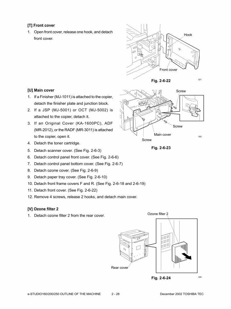
Screw
Screw
Main cover
Screw022
[U] Main cover
1. If a Finisher (MJ-1011) is attached to the copier,
detach the finisher plate and junction block.
2. If a JSP (MJ-5001) or OCT (MJ-5002) is
attached to the copier, detach it.
3. If an Original Cover (KA-1600PC), ADF
(MR-2012), or the RADF (MR-3011) is attached
to the copier, open it.
4. Detach the toner cartridge.
5. Detach scanner cover. (See Fig. 2-6-3)
6. Detach control panel front cover. (See Fig. 2-6-6)
7. Detach control panel bottom cover. (See Fig. 2-6-7)
8. Detach ozone cover. (See Fig. 2-6-9)
9. Detach paper tray cover. (See Fig. 2-6-10)
10. Detach front frame covers F and R. (See Fig. 2-6-18 and 2-6-19)
11. Detach front cover. (See Fig. 2-6-22)
12. Remove 4 screws, release 2 hooks, and detach main cover.
[T] Front cover
1. Open front cover, release one hook, and detach
front cover.
Fig. 2-6-22
Hook
Front cover
021
Fig. 2-6-23
[V] Ozone filter 2
1. Detach ozone filter 2 from the rear cover. Ozone filter 2
Rear cover
029Fig. 2-6-24
December 2002 TOSHIBA TEC 2 - 29 e-STUDIO160/200/250 OUTLINE OF THE MACHINE
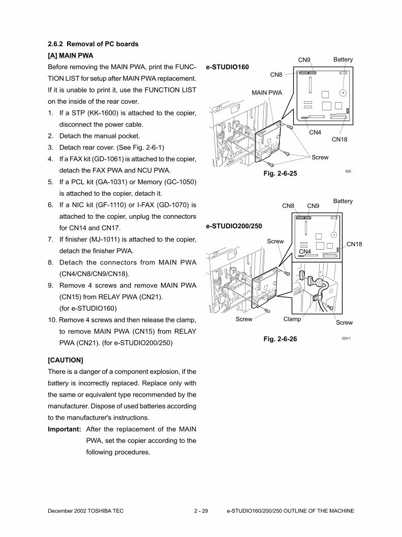
Fig. 2-6-25
CN8
CN9
CN18CN4
Screw
MAIN PWA
023
Battery
e-STUDIO160
e-STUDIO200/250
Fig. 2-6-26 023-1
Screw Clamp
Screw
CN4
CN8 CN9Battery
CN18
Screw
2.6.2 Removal of PC boards
[A] MAIN PWA
Before removing the MAIN PWA, print the FUNC-
TION LIST for setup after MAIN PWA replacement.
If it is unable to print it, use the FUNCTION LIST
on the inside of the rear cover.
1. If a STP (KK-1600) is attached to the copier,
disconnect the power cable.
2. Detach the manual pocket.
3. Detach rear cover. (See Fig. 2-6-1)
4. If a FAX kit (GD-1061) is attached to the copier,
detach the FAX PWA and NCU PWA.
5. If a PCL kit (GA-1031) or Memory (GC-1050)
is attached to the copier, detach it.
6. If a NIC kit (GF-1110) or I-FAX (GD-1070) is
attached to the copier, unplug the connectors
for CN14 and CN17.
7. If finisher (MJ-1011) is attached to the copier,
detach the finisher PWA.
8. Detach the connectors from MAIN PWA
(CN4/CN8/CN9/CN18).
9. Remove 4 screws and remove MAIN PWA
(CN15) from RELAY PWA (CN21).
(for e-STUDIO160)
10. Remove 4 screws and then release the clamp,
to remove MAIN PWA (CN15) from RELAY
PWA (CN21). (for e-STUDIO200/250)
[CAUTION]
There is a danger of a component explosion, if the
battery is incorrectly replaced. Replace only with
the same or equivalent type recommended by the
manufacturer. Dispose of used batteries according
to the manufacturer's instructions.
Important: After the replacement of the MAIN
PWA, set the copier according to the
following procedures.
e-STUDIO160/200/250 OUTLINE OF THE MACHINE 2 - 30 December 2002 TOSHIBA TEC
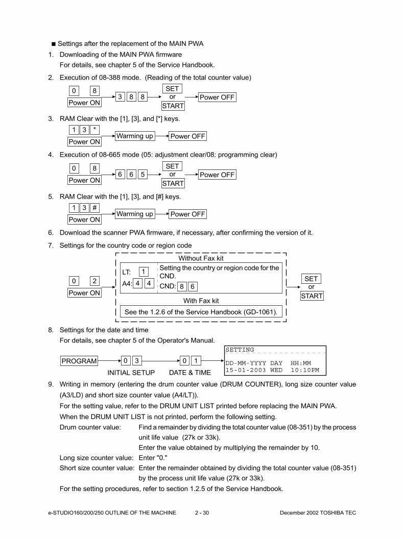
8. Settings for the date and time
For details, see chapter 5 of the Operator's Manual.
PROGRAM 0 3 10
INITIAL SETUP DATE & TIME
SETTING
DD-MM-YYYY DAY HH:MM15-01-2003 WED 10:10PM
Settings after the replacement of the MAIN PWA
1. Downloading of the MAIN PWA firmware
For details, see chapter 5 of the Service Handbook.
2. Execution of 08-388 mode. (Reading of the total counter value)
3. RAM Clear with the [1], [3], and [*] keys.
4. Execution of 08-665 mode (05: adjustment clear/08: programming clear)
5. RAM Clear with the [1], [3], and [#] keys.
Power ON
0 8 SET
Power OFFor
START
3 88
Power ON
1 *Power OFF
3Warming up
Power ON
1 #Power OFF
3Warming up
Power ON
0 8 SET
Power OFFor
START
6 56
6. Download the scanner PWA firmware, if necessary, after confirming the version of it.
7. Settings for the country code or region code
9. Writing in memory (entering the drum counter value (DRUM COUNTER), long size counter value
(A3/LD) and short size counter value (A4/LT)).
For the setting value, refer to the DRUM UNIT LIST printed before replacing the MAIN PWA.
When the DRUM UNIT LIST is not printed, perform the following setting.
Drum counter value: Find a remainder by dividing the total counter value (08-351) by the process
unit life value (27k or 33k).
Enter the value obtained by multiplying the remainder by 10.
Long size counter value: Enter "0."
Short size counter value: Enter the remainder obtained by dividing the total counter value (08-351)
by the process unit life value (27k or 33k).
For the setting procedures, refer to section 1.2.5 of the Service Handbook.
Power ON
0 2 SETor
START
1
44
Setting the country or region code for the
CND.
CND:
With Fax kit
See the 1.2.6 of the Service Handbook (GD-1061).
Without Fax kit
LT:
A4: 8 6

December 2002 TOSHIBA TEC 2 - 31 e-STUDIO160/200/250 OUTLINE OF THE MACHINE
10. Entering the adjustment value for the printing position.
Enter the setting value for the following 21 items.
For the setting values, refer to the FUNCTION LIST printed before replacing the MAIN PWA, or the
FUNCTION LIST on the inside of the rear cover of the copier.
When the FUNCTION LIST is not printed in 08-404/401/251/252, perform the following setting.
08-404: Enter the remainder obtained by dividing the total counter value (08-351) by the process
unit life value (27k or 33k).
08-401: Find a remainder by dividing the total counter value (08-351) by the process life unit value
(27k or 33k).
Enter the value obtained by multiplying the remainder by 4.7 (for e-STUDIO160/200 series)
or 4.5 (for e-STUDIO250 series).
08-251: When it was set before the MAIN PWA was replaced, perform the setting again.
08-252: Enter the remainder obtained by dividing the total counter value (08-351) by the PM life
value (81k or 99k).
When 08-251 is “0,” however, it is not necessary to enter the 08-252 value.
For the setting procedures, refer to sections 1.2.1 and 1.2.2 of the Service Handbook.
1: 05-205 (Developer bias DC adjustment)
2: 05-210 (Grid voltage initial value adjustment)
3: 05-220 Transfer H
4: 05-221 Transfer C
5: 05-233 Separation H
6: 05-234 Separation C
7: 05-235 Separation L
8: 05-400 (Printer primary scanning reproduction ratio)
9: 05-410 (Laser start position)
10: 05-421 (Printer secondary scanning reproduction ratio)
11: 05-440 (Leading edge)
12: 05-430 (Top margin)
13: 05-431 (Left margin)
14: 05-432 (Right margin)
15: 05-433 (Bottom margin)
16: 08-404 (Developer material counter)
17: 08-401 (Drum life counter)
18: 08-251 (PM counter setting value)
19: 08-252 (PM counter present value)
20: 08-446 Transfer ON position
21: 08-447 Transfer OFF position
11. Sensor test in the [1] [3] test mode.
1: Confirm whether the attached options are reflected on the bit information correctly.
2: Refer to 1.2.4 of the Service Handbook.
12. SRAM test/DRAM test/Clock IC test/CODEC test mode.
For details, see chapter 8 of the Operator’s Manual.

e-STUDIO160/200/250 OUTLINE OF THE MACHINE 2 - 32 December 2002 TOSHIBA TEC
[B] RELAY PWA
1. If a STP (KK-1600) is attached to the copier,
disconnect the power cable.
2. Detach the manual pocket.
3. Detach rear cover. (See Fig. 2-6-1)
4. If a FAX kit (GD-1061) is attached to the copier,
detach the FAX PWA and NCU PWA.
5. If a PCL kit (GA-1031) or Memory (GC-1050)
is attached to the copier, detach it.
6. If a NIC kit (GF-1110) or I-FAX (GD-1070) is
attached to the copier, unplug the connectors
for CN14 and CN17.
7. If finisher (MJ-1011) is attached to the copier,
detach the finisher PWA.
8. Remove MAIN PWA.
(See Fig. 2-6-25 and 2-6-26)
9. Detach all the connectors from RELAY PWA.
10. Remove 4 screws and remove RELAY PWA.
Fig. 2-6-27
RELAY PWA
ScrewRELAY PWA
024
[C] PC I/F PWA
1. If a STP (KK-1600) is attached to the copier,
disconnect the power cable.
2. Detach the manual pocket.
3. Detach rear cover. (See Fig. 2-6-1)
4. Remove one screw, detach PC I/F PWA cover,
and detach the connector.
5. Remove 2 screws and remove PC I/F PWA.
Fig. 2-6-28
PC I/F PWA PC I/F PWA
CN2
Screw
PC I/F PWA cover
Screw
025

December 2002 TOSHIBA TEC 2 - 33 e-STUDIO160/200/250 OUTLINE OF THE MACHINE
High voltage
power supply
Screw
Screw
High voltage
power supply026-2
[D] High voltage power supply
1. If a STP (KK-1600) is attached to the copier,
disconnect the power cable.
2. Detach the manual pocket.
3. Detach rear cover. (See Fig. 2-6-1)
4. If a PCL kit (GA-1031) is attached to the copier,
detach it.
5. If a NIC kit (GF-1110) or I-FAX (GD-1070) is
attached to the copier, unplug the connectors
for CN14 and CN17.
6. Remove 2 screws, release 2 clamps, and
detach HVPS cover.
Clamp
ClampHVPS cover
Screw
026-1
Fig. 2-6-29
7. Detach all the connectors, remove 4 screws,
then remove high voltage power supply.
Fig. 2-6-30
Screw
LVPS cover
LVPS
Screw
Screw
LVPS
Clamp
027-1
027-2
Screw
[E] LVPS
1. If a Finisher (MJ-1011) is attached to the copier,
detach the finisher plate and junction block.
2. If a JSP (MJ-5001) or OCT (MJ-5002) is
attached to the copier, detach it.
3. Detach the toner cartridge.
4. Detach ozone cover. (See Fig. 2-6-9)
5. Detach paper tray cover. (See Fig. 2-6-10)
6. Loosen 5 screws.
7. Remove one screw and detach LVPS cover. Fig. 2-6-31
8. Detach all the connectors and release one
clamps.
9. Remove 3 screws and remove LVPS.
Fig. 2-6-32
e-STUDIO160/200/250 OUTLINE OF THE MACHINE 2 - 34 December 2002 TOSHIBA TEC
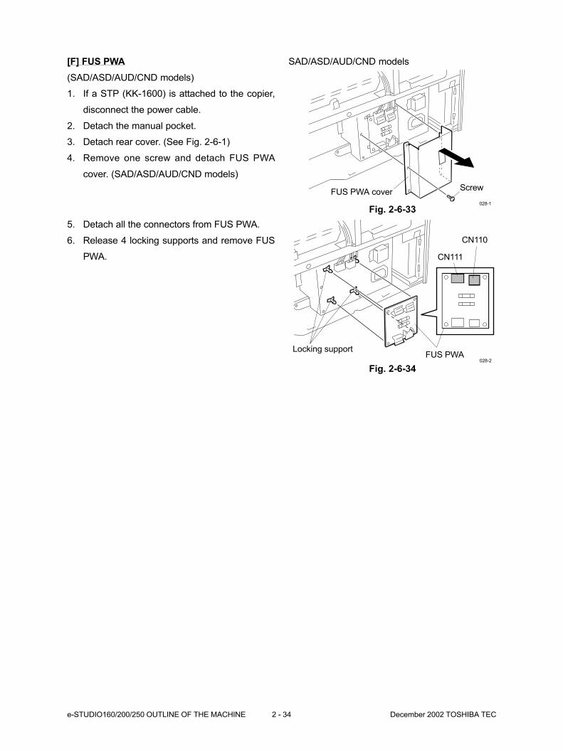
ScrewFUS PWA cover
CN111
CN110
Locking supportFUS PWA
028-1
028-2
Fig. 2-6-33
5. Detach all the connectors from FUS PWA.
6. Release 4 locking supports and remove FUS
PWA.
Fig. 2-6-34
[F] FUS PWA
(SAD/ASD/AUD/CND models)
1. If a STP (KK-1600) is attached to the copier,
disconnect the power cable.
2. Detach the manual pocket.
3. Detach rear cover. (See Fig. 2-6-1)
4. Remove one screw and detach FUS PWA
cover. (SAD/ASD/AUD/CND models)
SAD/ASD/AUD/CND models
3. COPYING PROCESS ............................... 3-1
3.1 Copying Process ....................................................................................... 3-1
3.2 Details of Copying Process ....................................................................... 3-2
3.3 List of Copying Process Conditions .......................................................... 3-9
3.4 Disassembly and Replacement ................................................................ 3-10
December 2002 TOSHIBA TEC 3 - 1 e-STUDIO160/200/250 COPYING PROCESS
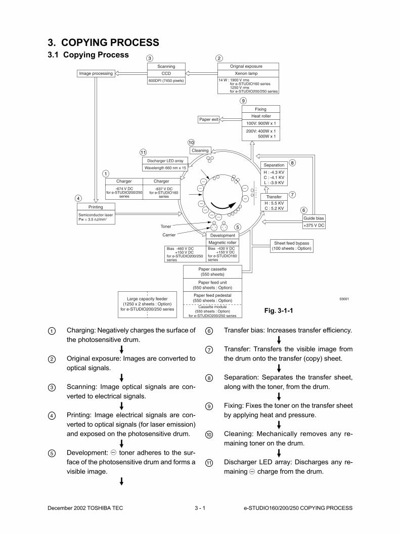
3. COPYING PROCESS3.1 Copying Process
Charging: Negatively charges the surface of
the photosensitive drum.
Original exposure: Images are converted to
optical signals.
Scanning: Image optical signals are con-
verted to electrical signals.
Printing: Image electrical signals are con-
verted to optical signals (for laser emission)
and exposed on the photosensitive drum.
Development: toner adheres to the sur-
face of the photosensitive drum and forms a
visible image.
Transfer bias: Increases transfer efficiency.
Transfer: Transfers the visible image from
the drum onto the transfer (copy) sheet.
Separation: Separates the transfer sheet,
along with the toner, from the drum.
Fixing: Fixes the toner on the transfer sheet
by applying heat and pressure.
Cleaning: Mechanically removes any re-
maining toner on the drum.
Discharger LED array: Discharges any re-
maining charge from the drum.
03001
Fig. 3-1-1
1
23
4
5
6
7
8
9
10
11
Scanning
Image processing CCD
600DPI (7450 pixels)
Orignal exposure
Xenon lamp
14 W : 1900 V rms for e-STUDIO160 series 1250 V rms for e-STUDIO200/250 series
Fixing
Heat roller
100V: 900W x 1
200V: 400W x 1500W x 1
Paper exit
Cleaning
Discharger LED array
Wavelength 660 nm x 15
-637 V DCfor e-STUDIO160
series
Printing
Semiconductor laserPw = 3.5 nJ/mm2
Toner
Carrier Development
Magnetic rollerBias -430 V DC +150 V DCfor e-STUDIO160series
Paper cassette(550 sheets)
Paper feed unit(550 sheets : Option)
Paper feed pedestal(550 sheets : Option)
Sheet feed bypass(100 sheets : Option)
Guide bias
+375 V DC
Transfer
H : 5.5 KVC : 5.2 KV
Separation
H : -4.3 KVC : -4.1 KVL : -3.9 KV
Cassette module(550 sheets : Option)
for e-STUDIO200/250 series
Large capacity feeder(1250 x 2 sheets : Option)
for e-STUDIO200/250 series
Bias -460 V DC +150 V DCfor e-STUDIO200/250series
-674 V DCfor e-STUDIO200/250
series
Charger Charger
e-STUDIO160/200/250 COPYING PROCESS 3 - 2 December 2002 TOSHIBA TEC
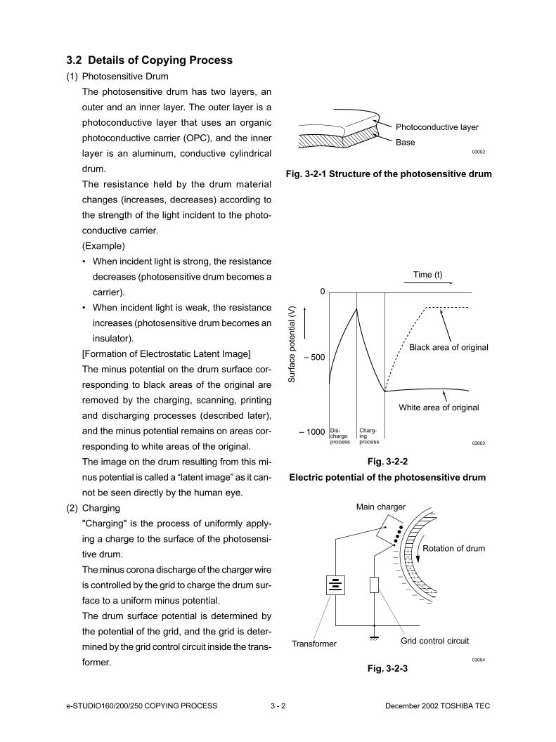
3.2 Details of Copying Process
(1) Photosensitive Drum
The photosensitive drum has two layers, an
outer and an inner layer. The outer layer is a
photoconductive layer that uses an organic
photoconductive carrier (OPC), and the inner
layer is an aluminum, conductive cylindrical
drum.
The resistance held by the drum material
changes (increases, decreases) according to
the strength of the light incident to the photo-
conductive carrier.
(Example)
• When incident light is strong, the resistance
decreases (photosensitive drum becomes a
carrier).
• When incident light is weak, the resistance
increases (photosensitive drum becomes an
insulator).
[Formation of Electrostatic Latent Image]
The minus potential on the drum surface cor-
responding to black areas of the original are
removed by the charging, scanning, printing
and discharging processes (described later),
and the minus potential remains on areas cor-
responding to white areas of the original.
The image on the drum resulting from this mi-
nus potential is called a “latent image” as it can-
not be seen directly by the human eye.
(2) Charging
"Charging" is the process of uniformly apply-
ing a charge to the surface of the photosensi-
tive drum.
The minus corona discharge of the charger wire
is controlled by the grid to charge the drum sur-
face to a uniform minus potential.
The drum surface potential is determined by
the potential of the grid, and the grid is deter-
mined by the grid control circuit inside the trans-
former.
Fig. 3-2-2
Electric potential of the photosensitive drum
Base
Photoconductive layer
Fig. 3-2-1 Structure of the photosensitive drum
03002
03003
0
– 500
– 1000
Time (t)
Black area of original
White area of original
Dis-chargeprocess
Charg-ingprocess
Surf
ace p
ote
ntial (V
)
03004
Transformer
Main charger
Rotation of drum
Grid control circuit
Fig. 3-2-3
December 2002 TOSHIBA TEC 3 - 3 e-STUDIO160/200/250 COPYING PROCESS
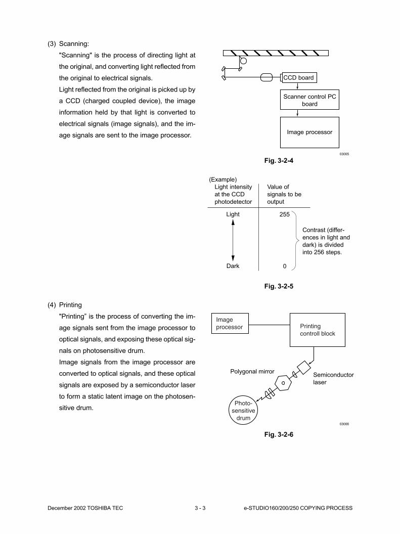
(3) Scanning:
"Scanning" is the process of directing light at
the original, and converting light reflected from
the original to electrical signals.
Light reflected from the original is picked up by
a CCD (charged coupled device), the image
information held by that light is converted to
electrical signals (image signals), and the im-
age signals are sent to the image processor.
(4) Printing
"Printing” is the process of converting the im-
age signals sent from the image processor to
optical signals, and exposing these optical sig-
nals on photosensitive drum.
Image signals from the image processor are
converted to optical signals, and these optical
signals are exposed by a semiconductor laser
to form a static latent image on the photosen-
sitive drum.
03005
CCD board
Scanner control PC
board
Image processor
(Example)
Light intensity
at the CCD
photodetector
Light
Dark
Value of
signals to be
output
255
0
Contrast (differ-
ences in light and
dark) is divided
into 256 steps.
Imageprocessor Printing
controll block
Photo-sensitive
drum03006
Polygonal mirrorSemiconductor
laser
Fig. 3-2-4
Fig. 3-2-5
Fig. 3-2-6
e-STUDIO160/200/250 COPYING PROCESS 3 - 4 December 2002 TOSHIBA TEC
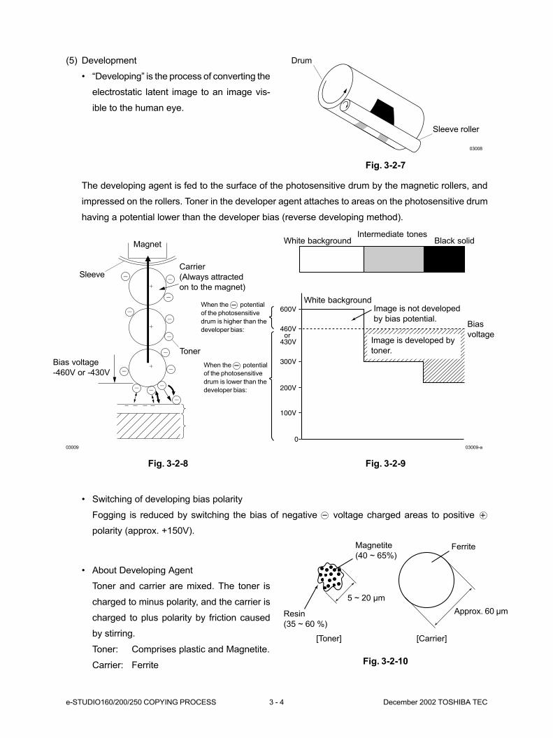
(5) Development
• “Developing” is the process of converting the
electrostatic latent image to an image vis-
ible to the human eye.
The developing agent is fed to the surface of the photosensitive drum by the magnetic rollers, and
impressed on the rollers. Toner in the developer agent attaches to areas on the photosensitive drum
having a potential lower than the developer bias (reverse developing method).
• Switching of developing bias polarity
Fogging is reduced by switching the bias of negative voltage charged areas to positive
polarity (approx. +150V).
• About Developing Agent
Toner and carrier are mixed. The toner is
charged to minus polarity, and the carrier is
charged to plus polarity by friction caused
by stirring.
Toner: Comprises plastic and Magnetite.
Carrier: Ferrite
0
100V
200V
300V
460Vor
430V
600V
Intermediate tonesBlack solidWhite background
White backgroundImage is not developed
by bias potential.Bias
voltage
When the potential
of the photosensitive
drum is higher than the
developer bias:
When the potential
of the photosensitive
drum is lower than the
developer bias:
03009-a
Magnetite
(40 ~ 65%)
Resin
(35 ~ 60 %)
[Toner] [Carrier]
Ferrite
5 ~ 20 µm
Approx. 60 µm
Image is developed by
toner.
Drum
Sleeve roller
03008
03009
Magnet
Toner
Carrier
(Always attracted
on to the magnet)
Bias voltage
-460V or -430V
Sleeve
Fig. 3-2-7
Fig. 3-2-9Fig. 3-2-8
Fig. 3-2-10
December 2002 TOSHIBA TEC 3 - 5 e-STUDIO160/200/250 COPYING PROCESS
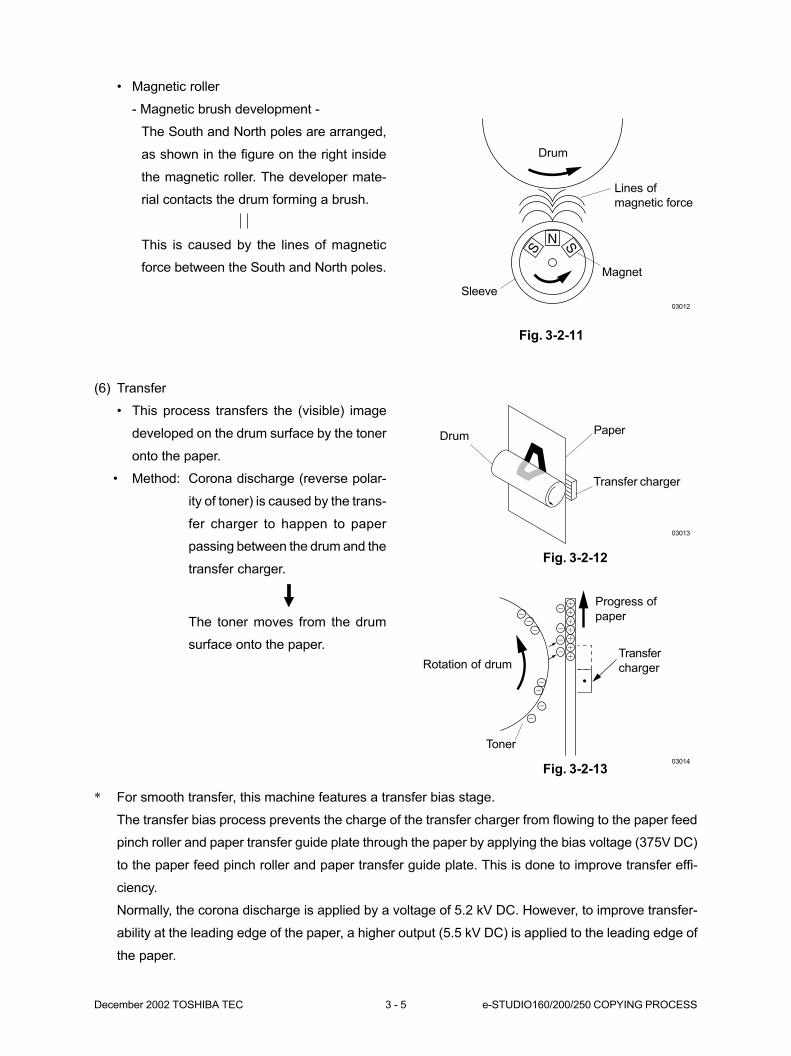
• Magnetic roller
- Magnetic brush development -
The South and North poles are arranged,
as shown in the figure on the right inside
the magnetic roller. The developer mate-
rial contacts the drum forming a brush.
This is caused by the lines of magnetic
force between the South and North poles.
N
S S
03012
Drum
Sleeve
Magnet
Lines of
magnetic force
Fig. 3-2-11
(6) Transfer
• This process transfers the (visible) image
developed on the drum surface by the toner
onto the paper.
• Method: Corona discharge (reverse polar-
ity of toner) is caused by the trans-
fer charger to happen to paper
passing between the drum and the
transfer charger.
The toner moves from the drum
surface onto the paper.
PaperDrum
Transfer charger
03013
03014
Toner
Progress of
paper
Rotation of drumTransfer
charger
Fig. 3-2-12
Fig. 3-2-13
* For smooth transfer, this machine features a transfer bias stage.
The transfer bias process prevents the charge of the transfer charger from flowing to the paper feed
pinch roller and paper transfer guide plate through the paper by applying the bias voltage (375V DC)
to the paper feed pinch roller and paper transfer guide plate. This is done to improve transfer effi-
ciency.
Normally, the corona discharge is applied by a voltage of 5.2 kV DC. However, to improve transfer-
ability at the leading edge of the paper, a higher output (5.5 kV DC) is applied to the leading edge of
the paper.
e-STUDIO160/200/250 COPYING PROCESS 3 - 6 December 2002 TOSHIBA TEC
* Output is controlled as follows to obtain satis-
factory separability and transferability.
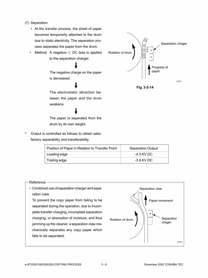
(7) Separation
• At the transfer process, the sheet of paper
becomes temporarily attached to the drum
due to static electricity. The separation pro-
cess separates the paper from the drum.
• Method: A negative DC bias is applied
to the separation charger.
The negative charge on the paper
is decreased.
The electrostatic attraction be-
tween the paper and the drum
weakens.
The paper is separated from the
drum by its own weight.
Position of Paper in Relation to Transfer Point Separation Output
Leading edge -4.3 KV DC
Trailing edge -3.9 KV DC
Reference
• Combined use of separation charger and sepa-
ration claw.
To prevent the copy paper from failing to be
separated during the operation, due to incom-
plete transfer charging, incomplete separation
charging, or absorption of moisture, and thus
jamming up the cleaner, a separation claw me-
chanically separates any copy paper which
fails to be separated.
Rotation of drum
Progress of
paper
03015
Separation chager
03016
Separation
chagerRotation of drum
Separation claw
Paper movement
Fig. 3-2-14
December 2002 TOSHIBA TEC 3 - 7 e-STUDIO160/200/250 COPYING PROCESS
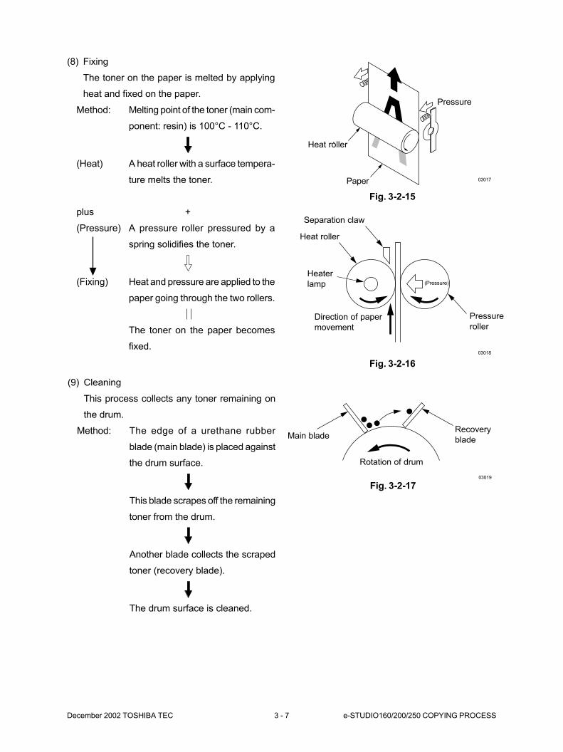
(8) Fixing
The toner on the paper is melted by applying
heat and fixed on the paper.
Method: Melting point of the toner (main com-
ponent: resin) is 100°C - 110°C.
(Heat) A heat roller with a surface tempera-
ture melts the toner.
plus +
(Pressure) A pressure roller pressured by a
spring solidifies the toner.
(Fixing) Heat and pressure are applied to the
paper going through the two rollers.
The toner on the paper becomes
fixed.
03017
03018
Separation claw
Paper
Heat roller
Pressure
Heat roller
Direction of paper
movement
Heater
lamp (Pressure)
Pressure
roller
Fig. 3-2-15
Fig. 3-2-16
(9) Cleaning
This process collects any toner remaining on
the drum.
Method: The edge of a urethane rubber
blade (main blade) is placed against
the drum surface.
This blade scrapes off the remaining
toner from the drum.
Another blade collects the scraped
toner (recovery blade).
The drum surface is cleaned.
03019
Rotation of drum
Main bladeRecovery
blade
Fig. 3-2-17
e-STUDIO160/200/250 COPYING PROCESS 3 - 8 December 2002 TOSHIBA TEC
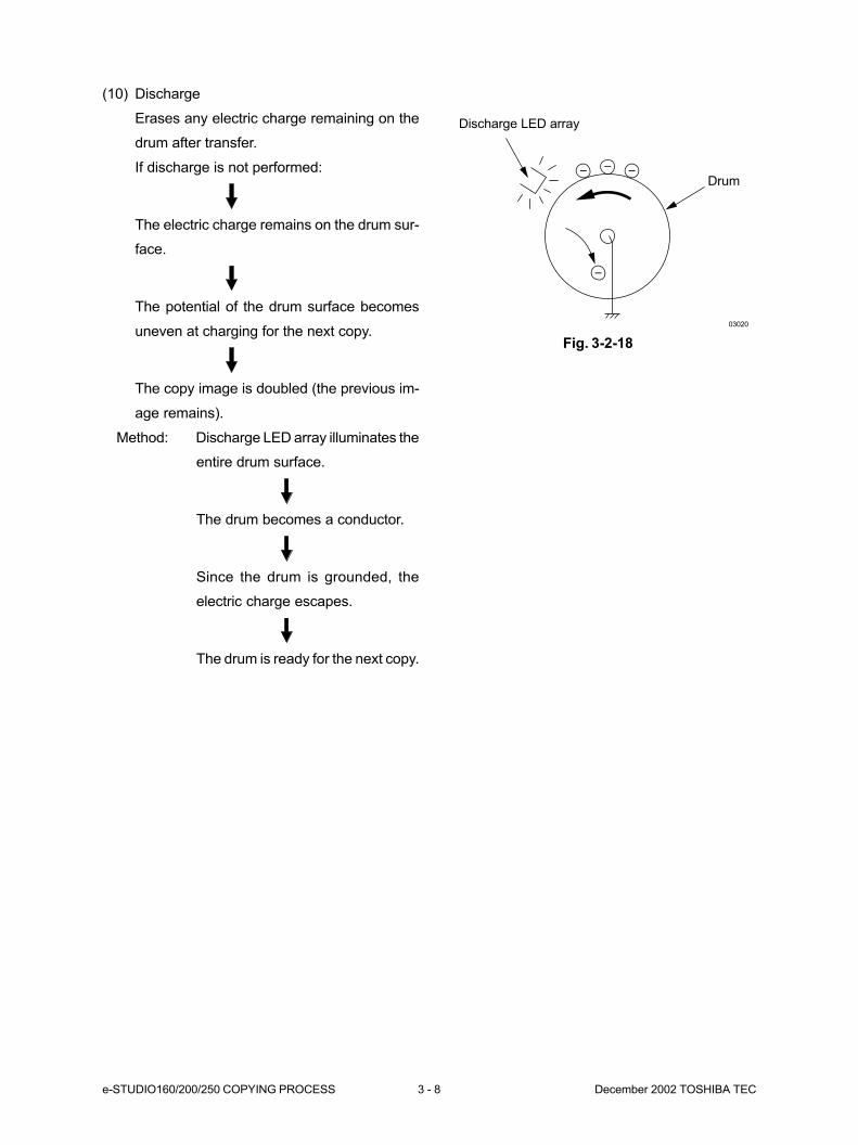
(10) Discharge
Erases any electric charge remaining on the
drum after transfer.
If discharge is not performed:
The electric charge remains on the drum sur-
face.
The potential of the drum surface becomes
uneven at charging for the next copy.
The copy image is doubled (the previous im-
age remains).
Method: Discharge LED array illuminates the
entire drum surface.
The drum becomes a conductor.
Since the drum is grounded, the
electric charge escapes.
The drum is ready for the next copy.
03020
Discharge LED array
Drum
Fig. 3-2-18
December 2002 TOSHIBA TEC 3 - 9 e-STUDIO160/200/250 COPYING PROCESS
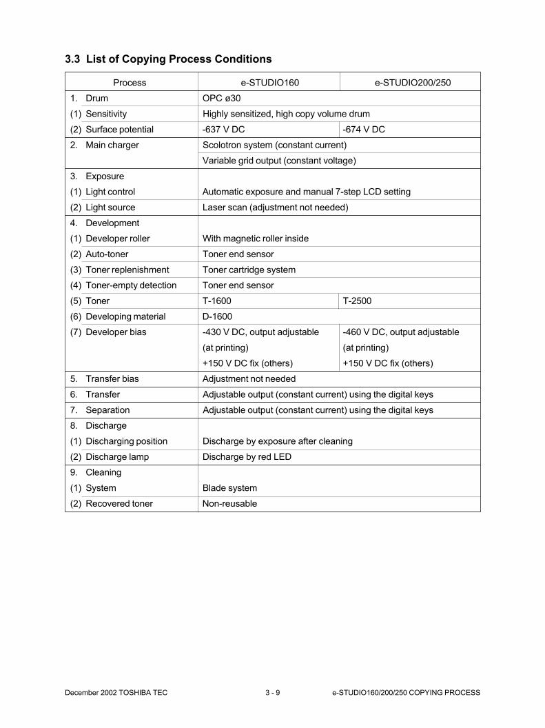
3.3 List of Copying Process Conditions
Process e-STUDIO160 e-STUDIO200/250
1. Drum OPC ø30
(1) Sensitivity Highly sensitized, high copy volume drum
(2) Surface potential -637 V DC -674 V DC
2. Main charger Scolotron system (constant current)
Variable grid output (constant voltage)
3. Exposure
(1) Light control Automatic exposure and manual 7-step LCD setting
(2) Light source Laser scan (adjustment not needed)
4. Development
(1) Developer roller With magnetic roller inside
(2) Auto-toner Toner end sensor
(3) Toner replenishment Toner cartridge system
(4) Toner-empty detection Toner end sensor
(5) Toner T-1600 T-2500
(6) Developing material D-1600
(7) Developer bias -430 V DC, output adjustable -460 V DC, output adjustable
(at printing) (at printing)
+150 V DC fix (others) +150 V DC fix (others)
5. Transfer bias Adjustment not needed
6. Transfer Adjustable output (constant current) using the digital keys
7. Separation Adjustable output (constant current) using the digital keys
8. Discharge
(1) Discharging position Discharge by exposure after cleaning
(2) Discharge lamp Discharge by red LED
9. Cleaning
(1) System Blade system
(2) Recovered toner Non-reusable

e-STUDIO160/200/250 COPYING PROCESS 3 - 10 December 2002 TOSHIBA TEC
Fig. 3-4-13-4-33
[B] Main charger wire/ Main charger grid
1. Remove the toner cartridge and the process
unit.
2. Remove 4 screws and detach the drum assem-
bly.
Fig. 3-4-2
3. Remove 2 screws and detach the DLE PWA
assembly.
Fig. 3-4-3
3-4-34
3-4-03
Spring
Separation claw
Drum assembly
Screw
Screw
Screw
Screw
DLE PWA assembly
[A] Separation claw
1. Remove the toner cartridge and the process
unit.
2. Detach the separation claw.
Note: Be careful not to be injured by the edges of
the separation claw and star wheel.
3.4 Disassembly and Replacement
When disassembling the process unit, pay special attention not to damage the drum and magnetic roller.
Also, be careful not to be injured by the edges of the parts.
December 2002 TOSHIBA TEC 3 - 11 e-STUDIO160/200/250 COPYING PROCESS
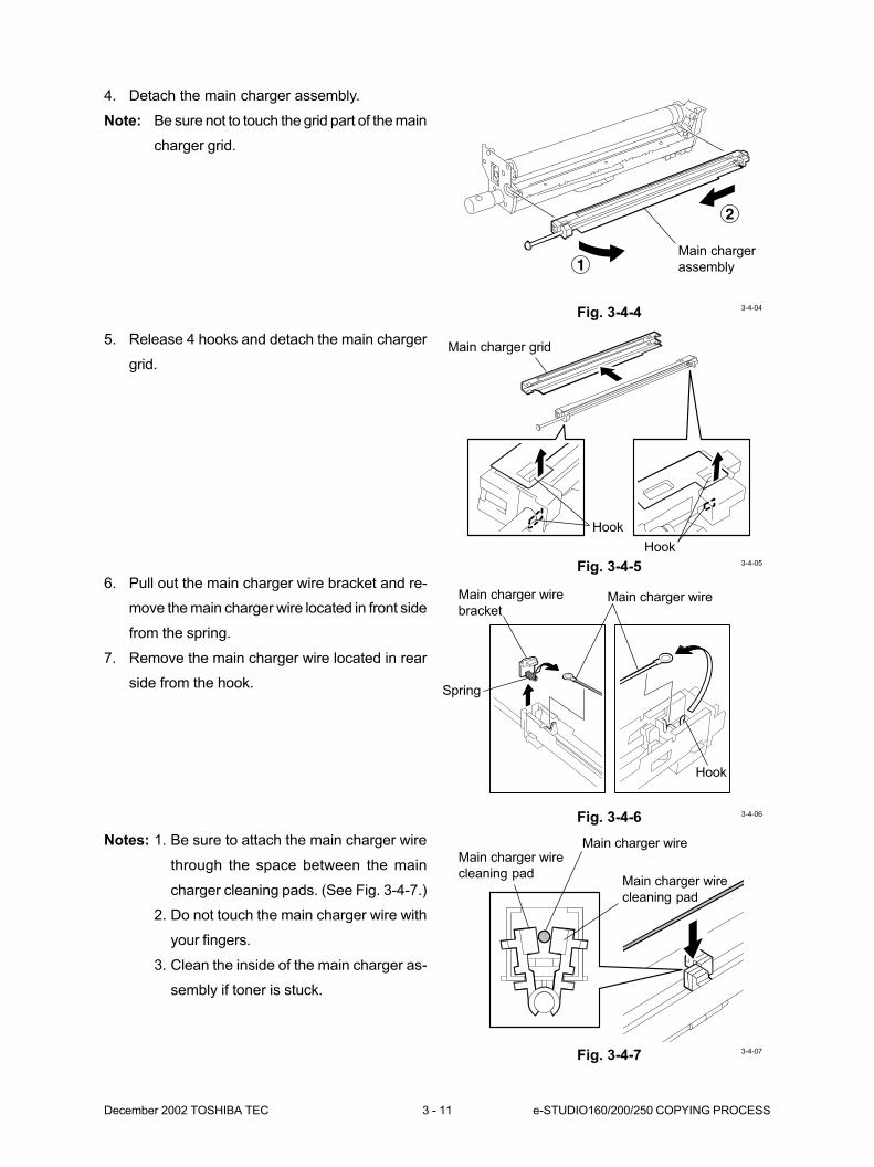
4. Detach the main charger assembly.
Note: Be sure not to touch the grid part of the main
charger grid.
Fig. 3-4-4
1
2
3-4-04
5. Release 4 hooks and detach the main charger
grid.
Main charger
assembly
Fig. 3-4-56. Pull out the main charger wire bracket and re-
move the main charger wire located in front side
from the spring.
7. Remove the main charger wire located in rear
side from the hook.
Fig. 3-4-6
Fig. 3-4-7
Main charger grid
Hook
Hook3-4-05
Main charger wireMain charger wire
bracket
Spring
Hook
3-4-06
Main charger wire
cleaning pad
Main charger wire
cleaning pad
Main charger wire
3-4-07
Notes: 1. Be sure to attach the main charger wire
through the space between the main
charger cleaning pads. (See Fig. 3-4-7.)
2. Do not touch the main charger wire with
your fingers.
3. Clean the inside of the main charger as-
sembly if toner is stuck.
e-STUDIO160/200/250 COPYING PROCESS 3 - 12 December 2002 TOSHIBA TEC
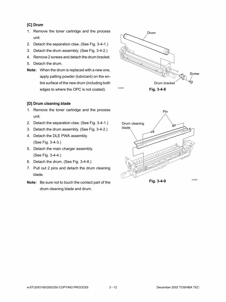
[C] Drum
1. Remove the toner cartridge and the process
unit.
2. Detach the separation claw. (See Fig. 3-4-1.)
3. Detach the drum assembly. (See Fig. 3-4-2.)
4. Remove 2 screws and detach the drum bracket.
5. Detach the drum.
Note: When the drum is replaced with a new one,
apply patting powder (lubricant) on the en-
tire surface of the new drum (including both
edges to where the OPC is not coated). Fig. 3-4-8
[D] Drum cleaning blade
1. Remove the toner cartridge and the process
unit.
2. Detach the separation claw. (See Fig. 3-4-1.)
3. Detach the drum assembly. (See Fig. 3-4-2.)
4. Detach the DLE PWA assembly.
(See Fig. 3-4-3.)
5. Detach the main charger assembly.
(See Fig. 3-4-4.)
6. Detach the drum. (See Fig. 3-4-8.)
7. Pull out 2 pins and detach the drum cleaning
blade.
Fig. 3-4-9Note: Be sure not to touch the contact part of the
drum cleaning blade and drum.
Drum
Screw
Drum bracket
3-8-08
Pin
Drum cleaning
blade
3-8-09
December 2002 TOSHIBA TEC 3 - 13 e-STUDIO160/200/250 COPYING PROCESS
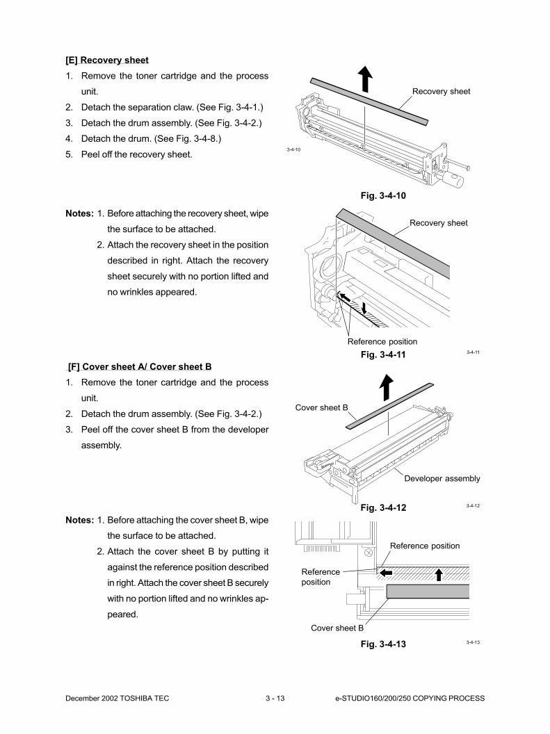
[E] Recovery sheet
1. Remove the toner cartridge and the process
unit.
2. Detach the separation claw. (See Fig. 3-4-1.)
3. Detach the drum assembly. (See Fig. 3-4-2.)
4. Detach the drum. (See Fig. 3-4-8.)
5. Peel off the recovery sheet.
Fig. 3-4-10
Fig. 3-4-11
[F] Cover sheet A/ Cover sheet B
1. Remove the toner cartridge and the process
unit.
2. Detach the drum assembly. (See Fig. 3-4-2.)
3. Peel off the cover sheet B from the developer
assembly.
Fig. 3-4-12
Notes: 1. Before attaching the cover sheet B, wipe
the surface to be attached.
2. Attach the cover sheet B by putting it
against the reference position described
in right. Attach the cover sheet B securely
with no portion lifted and no wrinkles ap-
peared.
Fig. 3-4-13
Recovery sheet
3-4-10
Recovery sheet
Reference position3-4-11
Developer assembly
Cover sheet B
3-4-12
3-4-13
Reference position
Cover sheet B
Reference
position
Notes: 1. Before attaching the recovery sheet, wipe
the surface to be attached.
2. Attach the recovery sheet in the position
described in right. Attach the recovery
sheet securely with no portion lifted and
no wrinkles appeared.
e-STUDIO160/200/250 COPYING PROCESS 3 - 14 December 2002 TOSHIBA TEC
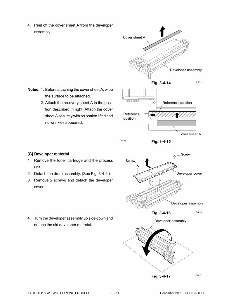
4. Peel off the cover sheet A from the developer
assembly.
Fig. 3-4-14
Fig. 3-4-15
[G] Developer material
1. Remove the toner cartridge and the process
unit.
2. Detach the drum assembly. (See Fig. 3-4-2.)
3. Remove 2 screws and detach the developer
cover.
Fig. 3-4-16
4. Turn the developer assembly up side down and
detach the old developer material.
Fig. 3-4-17
Cover sheet A
Developer assembly
3-4-14
3-4-15
Reference position
Cover sheet A
Reference
position
Screw
Screw
Developer cover
Developer assembly
3-4-16
Developer assembly
3-4-17
Notes: 1. Before attaching the cover sheet A, wipe
the surface to be attached.
2. Attach the recovery sheet A in the posi-
tion described in right. Attach the cover
sheet A securely with no portion lifted and
no wrinkles appeared.
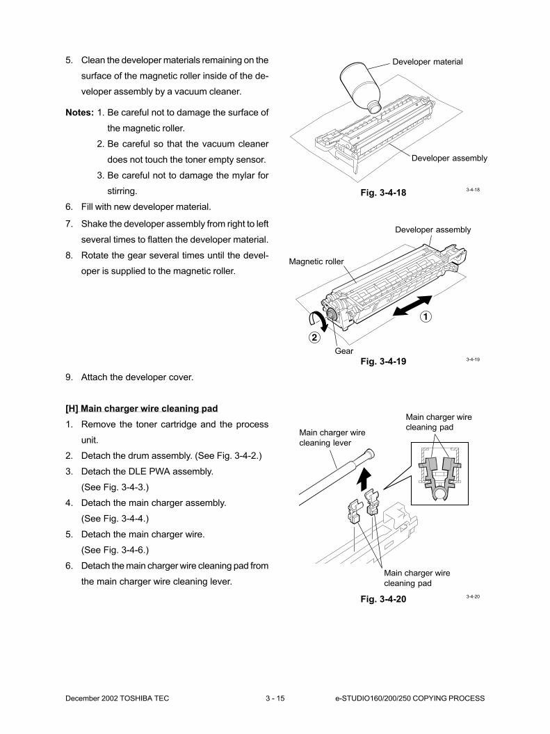
December 2002 TOSHIBA TEC 3 - 15 e-STUDIO160/200/250 COPYING PROCESS
Fig. 3-4-18
5. Clean the developer materials remaining on the
surface of the magnetic roller inside of the de-
veloper assembly by a vacuum cleaner.
Notes: 1. Be careful not to damage the surface of
the magnetic roller.
2. Be careful so that the vacuum cleaner
does not touch the toner empty sensor.
3. Be careful not to damage the mylar for
stirring.
6. Fill with new developer material.
7. Shake the developer assembly from right to left
several times to flatten the developer material.
8. Rotate the gear several times until the devel-
oper is supplied to the magnetic roller.
Fig. 3-4-19
9. Attach the developer cover.
[H] Main charger wire cleaning pad
1. Remove the toner cartridge and the process
unit.
2. Detach the drum assembly. (See Fig. 3-4-2.)
3. Detach the DLE PWA assembly.
(See Fig. 3-4-3.)
4. Detach the main charger assembly.
(See Fig. 3-4-4.)
5. Detach the main charger wire.
(See Fig. 3-4-6.)
6. Detach the main charger wire cleaning pad from
the main charger wire cleaning lever.
Fig. 3-4-20
Developer material
Developer assembly
3-4-18
1
2
Developer assembly
Magnetic roller
Gear3-4-19
Main charger wire
cleaning lever
Main charger wire
cleaning pad
Main charger wire
cleaning pad
3-4-20
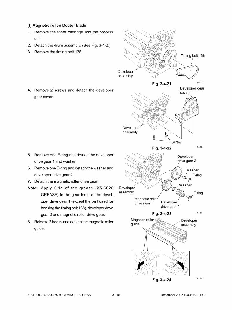
e-STUDIO160/200/250 COPYING PROCESS 3 - 16 December 2002 TOSHIBA TEC
[I] Magnetic roller/ Doctor blade
1. Remove the toner cartridge and the process
unit.
2. Detach the drum assembly. (See Fig. 3-4-2.)
3. Remove the timing belt 138.
Fig. 3-4-21
4. Remove 2 screws and detach the developer
gear cover.
Fig. 3-4-22
5. Remove one E-ring and detach the developer
drive gear 1 and washer.
6. Remove one E-ring and detach the washer and
developer drive gear 2.
7. Detach the magnetic roller drive gear.
Note: Apply 0.1g of the grease (X5-6020
GREASE) to the gear teeth of the devel-
oper drive gear 1 (except the part used for
hooking the timing belt 138), developer drive
gear 2 and magnetic roller drive gear. Fig. 3-4-23
Developer
assembly
Timing belt 138
3-4-21
Developer
assembly
Screw
Developer gear
cover
3-4-22
Developer
drive gear 2
Washer
E-ring
E-ring
Developer
drive gear 1
Washer
Magnetic roller
drive gear
Developer
assembly
3-4-23
8. Release 2 hooks and detach the magnetic roller
guide.
Fig. 3-4-24 3-4-24
Developer
assembly
Magnetic roller
guide
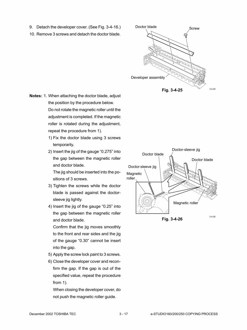
December 2002 TOSHIBA TEC 3 - 17 e-STUDIO160/200/250 COPYING PROCESS
9. Detach the developer cover. (See Fig. 3-4-16.)
10. Remove 3 screws and detach the doctor blade.
Fig. 3-4-25
Fig. 3-4-26
ScrewDoctor blade
Developer assembly
3-4-25
Doctor-sleeve jig
Doctor blade
Doctor blade
Magnetic roller
Doctor-sleeve jig
Magnetic
roller
3-4-26
Notes: 1. When attaching the doctor blade, adjust
the position by the procedure below.
Do not rotate the magnetic roller until the
adjustment is completed. If the magnetic
roller is rotated during the adjustment,
repeat the procedure from 1).
1) Fix the doctor blade using 3 screws
temporarily.
2) Insert the jig of the gauge “0.275” into
the gap between the magnetic roller
and doctor blade.
The jig should be inserted into the po-
sitions of 3 screws.
3) Tighten the screws while the doctor
blade is passed against the doctor-
sleeve jig lightly.
4) Insert the jig of the gauge “0.25” into
the gap between the magnetic roller
and doctor blade.
Confirm that the jig moves smoothly
to the front and rear sides and the jig
of the gauge “0.30” cannot be insert
into the gap.
5) Apply the screw lock paint to 3 screws.
6) Close the developer cover and recon-
firm the gap. If the gap is out of the
specified value, repeat the procedure
from 1).
When closing the developer cover, do
not push the magnetic roller guide.
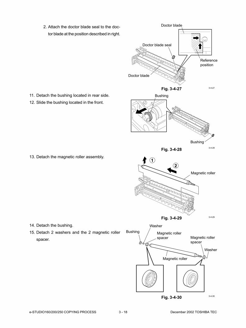
e-STUDIO160/200/250 COPYING PROCESS 3 - 18 December 2002 TOSHIBA TEC
Fig. 3-4-27
11. Detach the bushing located in rear side.
12. Slide the bushing located in the front.
Fig. 3-4-28
13. Detach the magnetic roller assembly.
Fig. 3-4-29
14. Detach the bushing.
15. Detach 2 washers and the 2 magnetic roller
spacer.
Fig. 3-4-30
Reference
position
Doctor blade
Doctor blade seal
Doctor blade
3-4-27
Bushing
Bushing
3-4-28
12
3-4-29
Magnetic roller
Bushing
Washer
Magnetic roller
spacer
Magnetic roller
Washer
Magnetic roller
spacer
3-4-30
2. Attach the doctor blade seal to the doc-
tor blade at the position described in right.
4. COPIER OPERATION .............................. 4-1
4.1 Operation Outline ...................................................................................... 4-1
4.2 Description of Operation ........................................................................... 4-1
4.2.1 Warming up .................................................................................. 4-1
4.2.2 Standby ........................................................................................ 4-2
4.2.3 Automatic feed copying using the START key ............................. 4-3
4.2.4 Bypass-feed copying .................................................................... 4-4
4.2.5 Interrupt copying .......................................................................... 4-4
4.3 Fault Detection .......................................................................................... 4-5
4.3.1 Classification of faults .................................................................. 4-5
4.3.2 Explanation of faults ..................................................................... 4-6
4.4 Flow Charts ............................................................................................... 4-9
4.4.1 At power ON time ......................................................................... 4-9
4.4.2 Copying at platen (Simplex → Simplex) ....................................... 4-11
4.4.3 Copying using cassette 1 ............................................................. 4-12
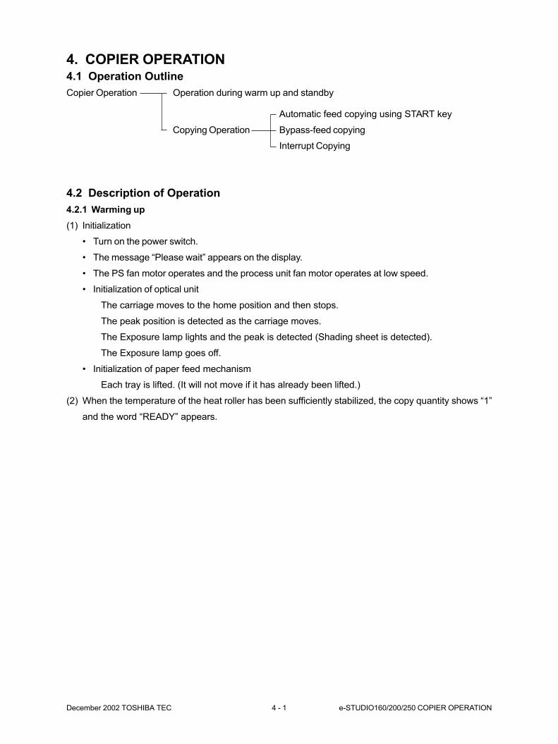
December 2002 TOSHIBA TEC 4 - 1 e-STUDIO160/200/250 COPIER OPERATION
4. COPIER OPERATION4.1 Operation Outline
Copier Operation Operation during warm up and standby
Automatic feed copying using START key
Copying Operation Bypass-feed copying
Interrupt Copying
4.2 Description of Operation
4.2.1 Warming up
(1) Initialization
• Turn on the power switch.
• The message “Please wait” appears on the display.
• The PS fan motor operates and the process unit fan motor operates at low speed.
• Initialization of optical unit
The carriage moves to the home position and then stops.
The peak position is detected as the carriage moves.
The Exposure lamp lights and the peak is detected (Shading sheet is detected).
The Exposure lamp goes off.
• Initialization of paper feed mechanism
Each tray is lifted. (It will not move if it has already been lifted.)
(2) When the temperature of the heat roller has been sufficiently stabilized, the copy quantity shows “1”
and the word “READY” appears.
e-STUDIO160/200/250 COPIER OPERATION 4 - 2 December 2002 TOSHIBA TEC
4.2.2 Standby
There are the following four kinds of power save functions:
1) Low Power Lowers the heater to a fixed temperature.
2) Sleep Turns the heater OFF.
3) Super Power Save Turns the main CPU OFF.
4) Weekly Timer Controls the Sleep mode for each day of the week.
1) Low Power
The Low Power mode function lowers the heater temperature to a fixed temperature after the set time has
elapsed, to save power consumption. The standard mode switches to the Low Power mode if no operation
has been performed for a fixed time. The standard switching time is 15 minutes. The time taken before
such switching can be changed (1 min. to 240 min.). The Low Power mode is deactivated when you press
the START key or an effective key under READY on the display or open and close the platen, while in the
Low Power mode. When the Low Power mode is deactivated, the program performs the following two
operations.
• Returns the display for the Low Power mode to the normal display.
• Returns the fusing temperature to the fusing temperature for standby.
2) Sleep
The Sleep mode function turns the heater power OFF after the set time has elapsed, to save power
consumption. The Low Power mode switches to the Sleep mode if no operation has been performed for a
fixed time. If the Low Power function is invalid, program so that such switching takes place from the
standard mode to the Sleep mode. The standard switching time is 15 minutes. The time taken before such
switching can be programmable (3 min. to 240 min.). The Sleep mode is deactivated when you press the
START key or an effective key under READY on the display or open and close the platen, while in the
Sleep mode. The Sleep mode will not switch to the Low Power mode.
3) Super Power Save
The Super Power Save mode function turns the CPU OFF to save power consumption. This mode is
switched to when you press the SUPER ENERGY SAVER key or when the Sleep mode timer stops.
When the Super Power Save mode is activated, the power of the main CPU turns OFF so that each device
is not controlled and the panel is not displayed on, either. The LED of the SUPER ENERGY SAVER key
only is lit. The standard mode is restored from the Super Power Save mode when you press the SUPER
ENERGY SAVER key again, open and close the platen, or open and close the document feeder (ADF or
RADF) or loading a document into the document feeder (ADF or RADF) if installed. At this time, the power
of the main CPU is turned on so that the operation begins with the same processing as when the power is
turned ON.
December 2002 TOSHIBA TEC 4 - 3 e-STUDIO160/200/250 COPIER OPERATION
4) Weekly Timer
The Weekly Timer function controls the Sleep mode for each day of the week. You can program this
function on the panel and determine the ON/OFF time (in minutes) for each day of the week from Sunday
through Saturday (one week). The Weekly Timer function itself can also be turned ON or OFF. Even if the
time is set, the Weekly Timer function does not work unless the function is ON.
4.2.3 Automatic feed copying using the START key
1) Press the START key.
2) The polygon motor and main motor start operation. At the same time, development bias positive
output begins and the discharge LED turns ON. The exhaust fan begins to turn at high speed. Paper
separation bias output turns ON (Low).
3) After the main motor reaches a constant speed, charge output begins.
4) A specified time after the charge output has begun, the development bias output is switched to nega-
tive. At the same time, paper separation bias output is turned OFF.
5) After the polygon motor has reached a constant speed, the laser is forced to turn OFF for synchroniz-
ing the UFE.
6) Paper pickup begins.
7) A required time after the feed sensor has turned ON, registration roller drive begins.
8) Laser exposure begins. At the same time, paper separation bias output is turned ON (High).
9) Transfer output turns ON (High). When a specified time has elapsed, the transfer output is switched to
Mid.
10) Transfer guide bias output turns ON. At the same time, the paper separation bias output is switched to
Low. When a specified time has elapsed, the paper separation bias is switched to Mid.
11) In a specified time after the feed sensor has turned OFF, the paper separation bias output is switched
to Low.
12) In a specified time after the feed sensor has turned OFF, the registration roller drive is stopped.
13) In a specified time after the paper separation bias output has been switched to Low, the transfer output
is switched to OFF.
14) The paper separation bias output is switched to High in a specitied period of time after the transfer
output is turned OFF.
15) When a specified time has elapsed, the transfer guide bias is turned OFF.
16) In a specified time after the exit sensor has turned OFF, the charge is turned OFF and the paper
separation bias output switched to OFF at the same time.
17) The polygon motor and main motor turn OFF.
18) The development bias output is reversed and paper separation bias output is turned ON (Low). At the
same time, the laser enable output is turned OFF.
19) The development bias output is turned OFF after a specified time, and the paper separation bias
output and the discharge LED output are turned OFF at the same time.
e-STUDIO160/200/250 COPIER OPERATION 4 - 4 December 2002 TOSHIBA TEC
4.2.4 Bypass-feed copying
Select Bypass Tray with the Paper Supply key on the display.
(1) Place paper in the bypass tray and adjust the document guides F and R to the paper width. The feed
sensor turns ON and the word “Ready for bypass feeding” appears.
(2) Press the START key. The message changes from “Ready for bypass feeding” to “COPYING.” The
polygon motor operates. The main motor operates, the process unit fan motor rotates at high speed,
and the discharge lamp lights. The drum, developer, heat roller, and exit roller move.
4.2.5 Interrupt copying
(1) Press the INTERRUPT key. The INTERRUPT key is illuminated and the message “Job interrupted”
appears. The present copy operation is stopped temporarily. The copy mode automatically becomes
the interrupt copy mode.
(2) Interrupt copying takes place.
(3) After the interrupt copying ends, the work “READY” appears. When INTERRUPT key is pressed
again, the illumination of the INTERRUPT key turns off and the copier is restored to its state prior to
the interruption. The message “Ready to resume job” appears.
(4) Press the START key and the operation prior to the interruption is resumed.
December 2002 TOSHIBA TEC 4 - 5 e-STUDIO160/200/250 COPIER OPERATION
4.3 Fault Detection
Errors are roughly classified into the following three kinds:
4.3.1 Classification of faults
A) Warning error An abnormal condition which can occur even during normal op-
eration, such as a paper empty state. After stoppage, the opera-
tion can be resumed. It can occur even during non-operation.
Display • Add paper
• Toner is low
• Drum life warning
B) Jam error An error where the copier can be restored when the operator re-
moves the cause of the abnormal condition from the machine.
Display • Toner empty
• Check process
• Misfeed in copier
• Misfeed in doc. feeder
• Misfeed in duplexer
• Misfeed in finisher
• Misfeed in bypass
C) Error subject to service call An error which has detected that the machine cannot be operated.
In this case, turn the power OFF.
Display • Call for service
e-STUDIO160/200/250 COPIER OPERATION 4 - 6 December 2002 TOSHIBA TEC
4.3.2 Explanation of faults
A)-1 Add paper
This error occurs when the sensor in the cassette tray detects the absence of paper.
Cause of occurrence : No paper is loaded into the cassette or the cassette is not correctly in-
stalled in the copier.
(This error message is also displayed when the cassette tray is not lifted
due to a fault of the lift-up motor, etc.)
Reset procedure : The error state can be reset by supplying paper or installing the cassette
again.
A)-2 Toner is low
This error occurs when the toner sensor detects the insufficiency of toner.
Reset procedure : Supply toner.
B)-1 Misfeed in copier
This error message is displayed when a paper jam has occurred in the transport path. There are the
following six kinds of jams including those for the installation of options.
FEED JAM
When paper is fed from the cassette of the copier, the sensors feed sensor and exit sensor turn
ON and OFF, in order. At this time, if the feed sensor or exit sensor does not turn ON for a fixed
time, a FEED JAM will be assumed.
• If the time taken from the moment when the registration clutch turns ON to the moment when
the exit sensor turns ON exceeds 3.02 seconds, the message “Misfeed in copier” will be dis-
played.
• If the time taken from the moment when the registration clutch turns ON to the moment when
the feed sensor turns OFF exceeds 5.38 seconds, the message “Misfeed in copier” will be
displayed.
Reset procedure : Open the side cover and remove the paper to turn the sensor OFF, then
close the side cover.

December 2002 TOSHIBA TEC 4 - 7 e-STUDIO160/200/250 COPIER OPERATION
EXIT JAM
When paper is fed from the cassette of the copier, the sensors feed sensor and exit sensor turn
ON and OFF, in order. At this time, if the exit sensor does not turn OFF for a fixed time after the
feed sensor of the copier has turned OFF, an EXIT JAM will be assumed.
• If the time taken from the moment when the feed sensor turns OFF to the moment when the
exit sensor turns OFF exceeds 3.12 seconds, the message “Misfeed in copier” will be dis-
played.
Reset procedure : Open the side cover and remove the paper to turn the sensor OFF, then
close the side cover.
The following are jams which can occur when options are installed.
SFB
When paper is loaded into the SFB, the SFB feed sensor detects the presence of paper. The SFB
clutch motor turns ON to pick up the paper. At this time, if the feed sensor of the copier does not
detect the presence of paper even after a fixed time has elapsed, SFB miss feed will be assumed
and the message “Misfeed in bypass” will be displayed.
Reset procedure : Remove the jammed paper and remove all the paper remaining in the tray
of the SFB to turn OFF the SFB feed sensor.
ADU
When performing duplex copying, the one-side-printed paper passes through the ADU. At this
time, if the sensors (2 pcs.) in the ADU do not turn ON for a fixed time, ADU miss feed will be
assumed and the message “Misfeed in duplexer” will be displayed.
Reset procedure : Open the ADU and remove the jammed paper to turn OFF the ADU sen-
sors, then close the cover.
PFU
With the PFU installed, if paper feed from the PFU is selected, the exit sensor detects the pres-
ence or absence of paper. Press the START button to turn ON the PFU clutch motor to pick up the
paper. At this time, if the exit sensor of the copier does not turn ON for a fixed time, PFU miss feed
will be assumed and the message “Misfeed in copier” will be displayed.
Reset procedure : Open the PFU cover or copier side cover and remove the jammed paper.
e-STUDIO160/200/250 COPIER OPERATION 4 - 8 December 2002 TOSHIBA TEC
PFP
With the PFP installed, if paper feed from the PFP is selected, the PFP paper feed sensor Upper
(Lower) sensor detects the presence or absence of paper. The one in parentheses applies when
the cassette module is installed. Press the START button to turn ON the PFP clutch motor to pick
up the paper. At this time, if the PFP paper feed sensor Upper (Lower) sensor does not turn ON
for a fixed time, PFP miss feed will be assumed and the message “Misfeed in copier” will be
displayed.
Reset procedure : Open the PFP cover or copier side cover and remove the jammed paper.
B)-2 Clear misfed document
With the optional ADF or RADF installed, this message is displayed when a document jam has occurred.
Reset procedure : Open the ADF cover or RADF cover and remove the jammed document.
B)-3 Toner empty
When a fixed number of sheets are printed after a Toner Low state has been detected, a Toner Empty
state will be assumed to stop the printing. If a Toner Empty state occurs, printing cannot be performed
until toner is supplied.
Reset procedure : Supply toner.
B)-4 Check process
This message is displayed when some trouble has occurred in the process unit. It is also displayed
when the life of the process unit has been reached.
Reset procedure : Remove and install the process unit or replace it.
C) Call for service
If this message is displayed, none of the operations can be performed. When you press the CLEAR/
STOP key and 8 key at the same time while the message is displayed, the error code will appear on the
display. The explanation of the error code is written in the “SERVICE HANDBOOK.”

December 2002 TOSHIBA TEC 4 - 9 e-STUDIO160/200/250 COPIER OPERATION
4.4 Flow Charts
4.4.1 At power ON time
Main switch ON
NO
Cover open?
NO
Paperpresent oversensor? *1
Power supply unitfan motor ON
Process unit fanmotor at low speed
Heater ON
"C95"
YES
Cover open
NO
Power supplyunit fan motor
NG
YES
Service call
"E03"
YES
Paper jam
NO
Processunit fan motor
NG?
"C96"
YES
Service call
NO
End of drum?YES
End of drum
Polygon motor ON
A
Feed sensor
Exit sensor
Option cassette feed sensor(with PFU/PFP installed)
PFP paper feed sensor (Upper)(with PFP installed)
ADU paper jam sensor (Upper/Lower)(with ADU installed)
*1 hinds of sensors
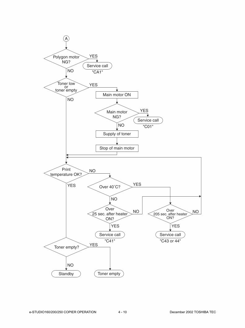
e-STUDIO160/200/250 COPIER OPERATION 4 - 10 December 2002 TOSHIBA TEC
A
NO
Polygon motorNG?
"CA1"
YES
Service call
Main motor ON
"C01"NO
Main motorNG?
YES
Service call
Supply of toner
Stop of main motor
NO
Toner lowor
toner emptyYES
"C41"
NO
Over 40˚C?
YES
Over25 sec. after heater
ON?
YES
NONO
Service call
"C43 or 44"
YES
Over205 sec. after heater
ON?
Service call
YES
Printtemperature OK?
NO
Toner empty?
NO
Standby Toner empty
YES
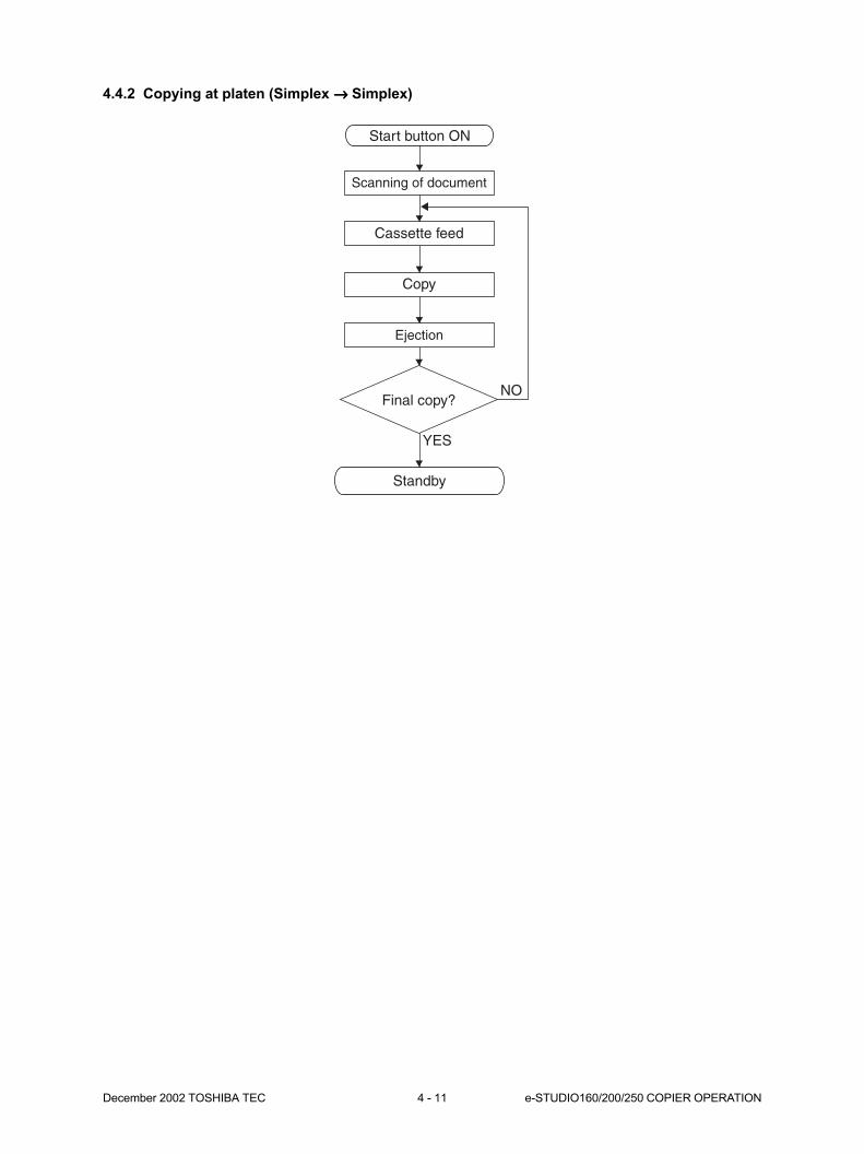
December 2002 TOSHIBA TEC 4 - 11 e-STUDIO160/200/250 COPIER OPERATION
4.4.2 Copying at platen (Simplex →→→→→ Simplex)
Standby
Start button ON
Scanning of document
Cassette feed
Copy
Ejection
NOFinal copy?
YES

e-STUDIO160/200/250 COPIER OPERATION 4 - 12 December 2002 TOSHIBA TEC
Start button ON
Transfer system control
YES
Process system control Optical system control
End of opticalsystem control
Main motor ONPolygon motor ONProcess unit fan motor high speed rotationDevelopment bias ONSeparation bias ONCharge bias ONDischarge lamp ON
Main motorOK?
Pickup clutch ON
Retraction of carriage
Black shading
Exposure lamp ON
Stop of carriage
Advance of carriage
White shading
Scanning of document
Stop of carriage
Exposure lamp OFF
Retraction of carriage
Stop of carriage
End of processsystem control
Polygon motor OFF
Laser ON
Transfer bias ON
Transfer guide bias ON
Laser OFF
Transfer bias OFF
Transfer guide bias OFF
NG
Paper jam
"E01"
NO
Service call
"C01"YES
Polygon motorOK?
NO
Service call
"CA1"
YES
Remainingcopy count 0?
OK
Exit sensorcheck 1
NG
Paper jam
"E02"OK
Exit sensorcheck 2
NO
NO
Service call
"CA2"YES
HSYNCOK
YES
Remainingcopy count 0?
Pickup clutch OFF
Ragistration rollerclutch ON
Ragistration rollerclutch OFF
NO
Charge bias OFFMain motor OFFDevelopment bias OFFSeparation bias OFFDischarge lamp OFFProcess unit fan motor low speed rotation
Standby
4.4.3 Copying using cassette 1
5. DISPLAY UNIT.......................................... 5-1
5.1 Detailed Drawing of the Control Panel and the Display Panel .................. 5-1
5.2 Items Shown on the Display Panel ........................................................... 5-2
5.2.1 Display during normal copying ..................................................... 5-2
5.2.2 Display in the event of faulty conditions ....................................... 5-4
5.3 Relation between Copier Conditions and Operator’s Actions ................... 5-12
5.4 Description of Operation ........................................................................... 5-13
5.4.1 Dot matrix LCD circuit .................................................................. 5-13
5.4.2 LED display circuit ........................................................................ 5-17
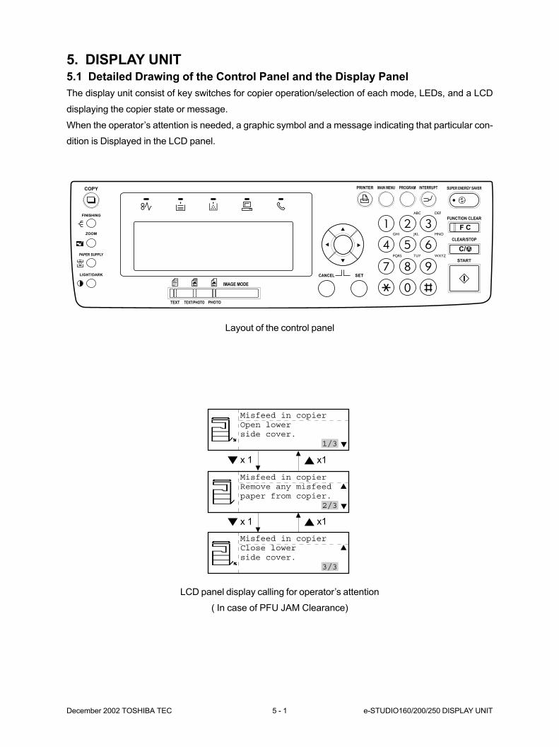
December 2002 TOSHIBA TEC 5 - 1 e-STUDIO160/200/250 DISPLAY UNIT
5. DISPLAY UNIT5.1 Detailed Drawing of the Control Panel and the Display Panel
The display unit consist of key switches for copier operation/selection of each mode, LEDs, and a LCD
displaying the copier state or message.
When the operator’s attention is needed, a graphic symbol and a message indicating that particular con-
dition is Displayed in the LCD panel.
Layout of the control panel
LCD panel display calling for operator’s attention
( In case of PFU JAM Clearance)
Misfeed in copierOpen lowerside cover.
1/3
Misfeed in copierRemove any misfeedpaper from copier.
2/3
Misfeed in copierClose lowerside cover.
3/3
x 1 x1
x 1 x1
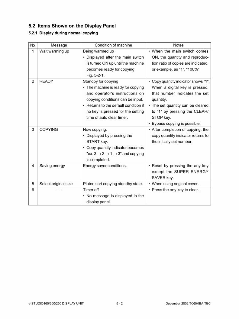
e-STUDIO160/200/250 DISPLAY UNIT 5 - 2 December 2002 TOSHIBA TEC
5.2 Items Shown on the Display Panel
5.2.1 Display during normal copying
No.
1
2
3
4
5
6
Message
Wait warming up
READY
COPYING
Saving energy
Select original size
-----
Condition of machine
Being warmed up
• Displayed after the main switch
is turned ON up until the machine
becomes ready for copying.
Fig. 5-2-1.
Standby for copying
• The machine is ready for copying
and operator's instructions on
copying conditions can be input.
• Returns to the default condition if
no key is pressed for the setting
time of auto clear timer.
Now copying.
• Displayed by pressing the
START key.
• Copy quantity indicator becomes
"ex. 3 → 2 → 1 → 3" and copying
is completed.
Energy saver conditions.
Platen sort copying standby state.
Timer off
• No message is displayed in the
display panel.
Notes
• When the main switch comes
ON, the quantity and reproduc-
tion ratio of copies are indicated,
or example, as "1", "100%".
• Copy quantity indicator shows "1".
When a digital key is pressed,
that number indicates the set
quantity.
• The set quantity can be cleared
to "1" by pressing the CLEAR/
STOP key.
• Bypass copying is possible.
• After completion of copying, the
copy quantity indicator returns to
the initially set number.
• Reset by pressing the any key
except the SUPER ENERGY
SAVER key.
• When using original cover.
• Press the any key to clear.
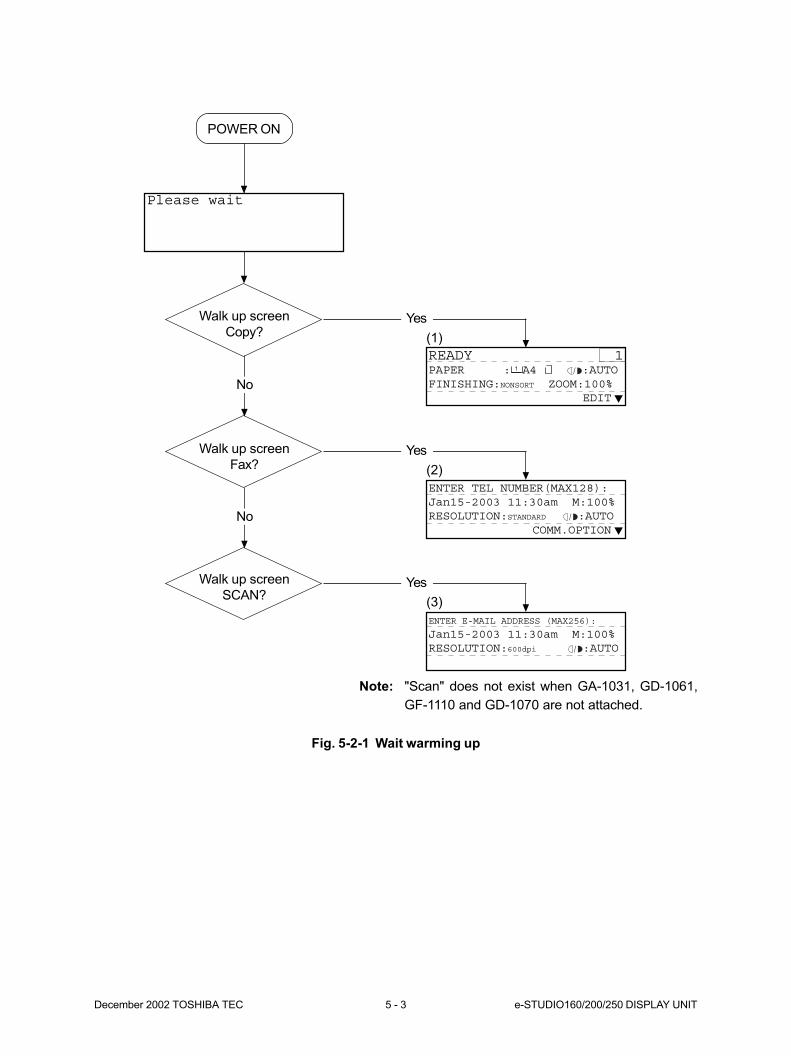
December 2002 TOSHIBA TEC 5 - 3 e-STUDIO160/200/250 DISPLAY UNIT
Fig. 5-2-1 Wait warming up
POWER ON
Walk up screen
Copy?
Please wait
No
Walk up screen
Fax?
No
Walk up screen
SCAN?
Yes
READY 1PAPER : A4 :AUTOFINISHING:NONSORT ZOOM:100%
EDIT
(1)
Yes
ENTER TEL NUMBER(MAX128):Jan15-2003 11:30am M:100%RESOLUTION:STANDARD :AUTO
COMM.OPTION
(2)
Yes
ENTER E-MAIL ADDRESS (MAX256):
Jan15-2003 11:30am M:100%RESOLUTION:600dpi :AUTO
(3)
Note: "Scan" does not exist when GA-1031, GD-1061,
GF-1110 and GD-1070 are not attached.
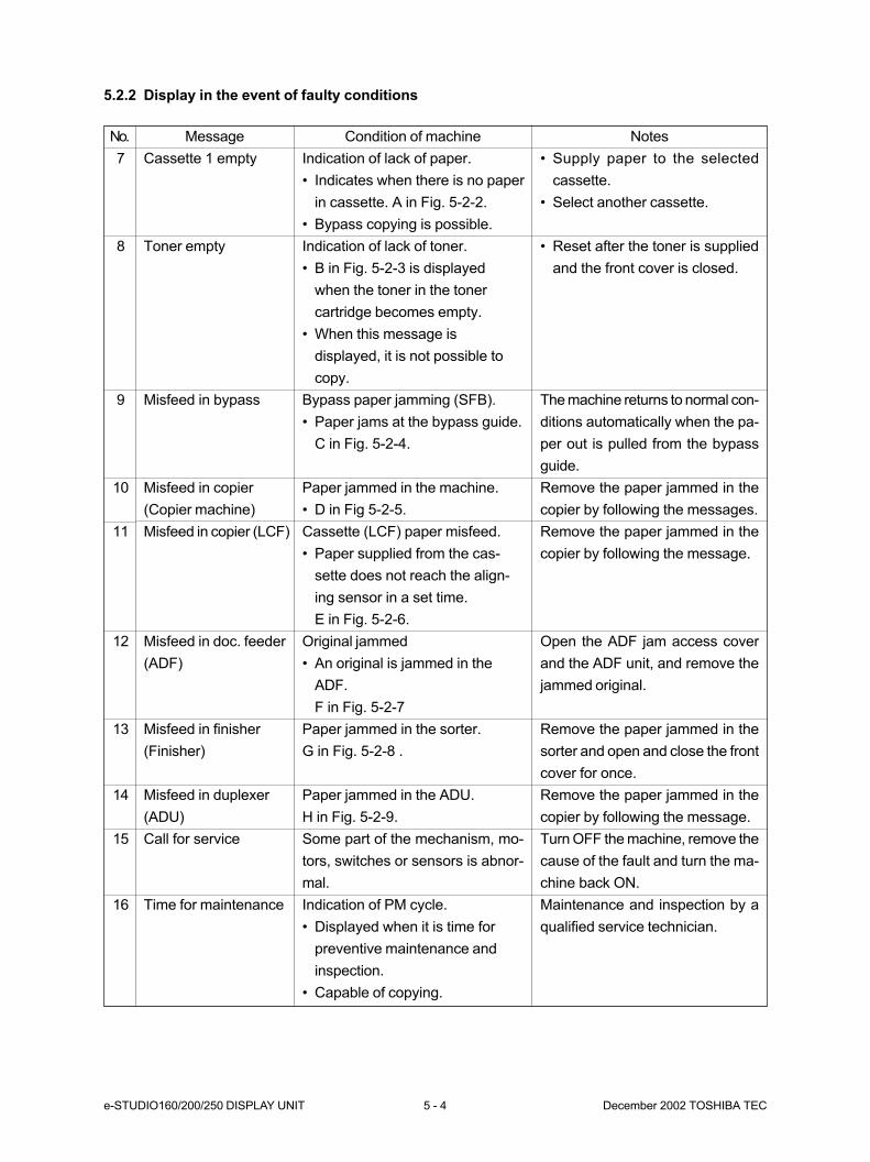
e-STUDIO160/200/250 DISPLAY UNIT 5 - 4 December 2002 TOSHIBA TEC
5.2.2 Display in the event of faulty conditions
No.
7
8
9
10
11
12
13
14
15
16
Message
Cassette 1 empty
Toner empty
Misfeed in bypass
Misfeed in copier
(Copier machine)
Misfeed in copier (LCF)
Misfeed in doc. feeder
(ADF)
Misfeed in finisher
(Finisher)
Misfeed in duplexer
(ADU)
Call for service
Time for maintenance
Condition of machine
Indication of lack of paper.
• Indicates when there is no paper
in cassette. A in Fig. 5-2-2.
• Bypass copying is possible.
Indication of lack of toner.
• B in Fig. 5-2-3 is displayed
when the toner in the toner
cartridge becomes empty.
• When this message is
displayed, it is not possible to
copy.
Bypass paper jamming (SFB).
• Paper jams at the bypass guide.
C in Fig. 5-2-4.
Paper jammed in the machine.
• D in Fig 5-2-5.
Cassette (LCF) paper misfeed.
• Paper supplied from the cas-
sette does not reach the align-
ing sensor in a set time.
E in Fig. 5-2-6.
Original jammed
• An original is jammed in the
ADF.
F in Fig. 5-2-7
Paper jammed in the sorter.
G in Fig. 5-2-8 .
Paper jammed in the ADU.
H in Fig. 5-2-9.
Some part of the mechanism, mo-
tors, switches or sensors is abnor-
mal.
Indication of PM cycle.
• Displayed when it is time for
preventive maintenance and
inspection.
• Capable of copying.
Notes
• Supply paper to the selected
cassette.
• Select another cassette.
• Reset after the toner is supplied
and the front cover is closed.
The machine returns to normal con-
ditions automatically when the pa-
per out is pulled from the bypass
guide.
Remove the paper jammed in the
copier by following the messages.
Remove the paper jammed in the
copier by following the message.
Open the ADF jam access cover
and the ADF unit, and remove the
jammed original.
Remove the paper jammed in the
sorter and open and close the front
cover for once.
Remove the paper jammed in the
copier by following the message.
Turn OFF the machine, remove the
cause of the fault and turn the ma-
chine back ON.
Maintenance and inspection by a
qualified service technician.
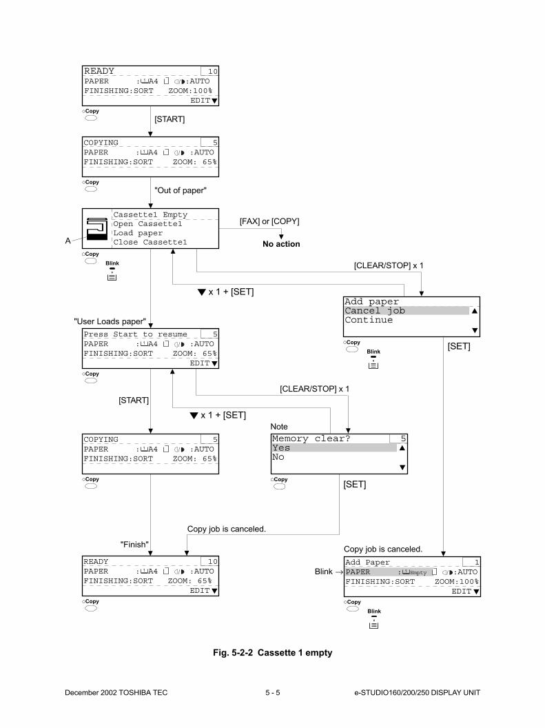
December 2002 TOSHIBA TEC 5 - 5 e-STUDIO160/200/250 DISPLAY UNIT
Copy
Copy
Fig. 5-2-2 Cassette 1 empty
COPYING 5PAPER : A4 :AUTOFINISHING:SORT ZOOM: 65%
[START]
READY 10PAPER : A4 :AUTOFINISHING:SORT ZOOM:100%
EDIT
"Out of paper"
A
Cassette1 EmptyOpen Cassette1Load paperClose Cassette1
Blink
Copy
Copy
[FAX] or [COPY]
No action
Add paperCancel jobContinue"User Loads paper"
COPYING 5PAPER : A4 :AUTOFINISHING:SORT ZOOM: 65%
[START]
Press Start to resume 5PAPER : A4 :AUTOFINISHING:SORT ZOOM: 65%
EDIT
READY 10PAPER : A4 :AUTOFINISHING:SORT ZOOM: 65%
EDIT
"Finish"
Copy
Copy
Copy
Memory clear? 5YesNo
Copy
[CLEAR/STOP] x 1
x 1 + [SET]
[CLEAR/STOP] x 1
x 1 + [SET]
Copy job is canceled.
[SET]
[SET]
Copy job is canceled.
Blink
Note
Copy
Blink
Add Paper 1PAPER : Empty :AUTOFINISHING:SORT ZOOM:100%
EDIT
Blink →
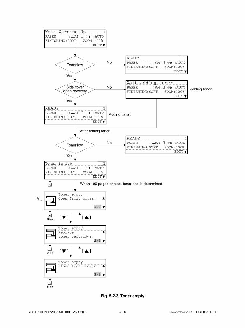
e-STUDIO160/200/250 DISPLAY UNIT 5 - 6 December 2002 TOSHIBA TEC
Fig. 5-2-3 Toner empty
Wait Warming Up 1PAPER : A4 :AUTOFINISHING:SORT ZOOM:100%
EDIT
Toner low
Side coveropen recovery
Yes
Yes
READY 1PAPER : A4 :AUTOFINISHING:SORT ZOOM:100%
EDIT
Toner low
Yes
READY 1PAPER : A4 :AUTOFINISHING:SORT ZOOM:100%
EDIT
No
Wait adding toner 1PAPER : A4 :AUTOFINISHING:SORT ZOOM:100%
EDIT
NoAdding toner.
Adding toner.
After adding toner.
READY 1PAPER : A4 :AUTOFINISHING:SORT ZOOM:100%
EDIT
No
B
Toner emptyOpen front cover.
1/3
Toner emptyReplacetoner cartridge.
2/3
Toner emptyClose front cover.
3/3
[ ] [ ]
Toner is low 1PAPER : A4 :AUTOFINISHING:SORT ZOOM:100%
EDIT
When 100 pages printed, toner end is determined
Blink
[ ] [ ]Blink
Blink

December 2002 TOSHIBA TEC 5 - 7 e-STUDIO160/200/250 DISPLAY UNIT
Fig. 5-2-4 Misfeed in bypass (SFB)
Fig. 5-2-5 Misfeed in copier
C
Misfeed in bypassRemove any misfeedpaper. Then setthem again. 1/1
Misfeed in copierOpen side coverof the copier.
1/4
Misfeed in copierRelease light bluefuser latches.
2/4
Misfeed in copierRemove any misfeedpaper from copier.
3/4
x1 x1
D
Misfeed in copierClose side coverof the copier.
4/4
x1 x1
x1 x1

e-STUDIO160/200/250 DISPLAY UNIT 5 - 8 December 2002 TOSHIBA TEC
Fig. 5-2-6 Misfeed in copier (LCF)
E
x1 x1
x1 x1
x1 x1
x1 x1
x1 x1
x1 x1
x1 x1
x1 x1
Misfeed in copierOpen side coverof the copier.
1/9
Misfeed in copierRemove any misfeedpaper from copier.
2/9
Misfeed in copierClose side coverof the copier.
3/9
Misfeed in copierOpen lowerside cover.
4/9
Misfeed in copierRemove any misfeedpaper from copier.
5/9
Misfeed in copierClose lowerside cover.
6/9
Misfeed in copierOpen side coverof Large-Capacity-Feeder. 7/9
Misfeed in copierRemove any misfeedpaper from copier.
8/9
Misfeed in copierClose side coverof Large-Capacity-Feeder. 9/9
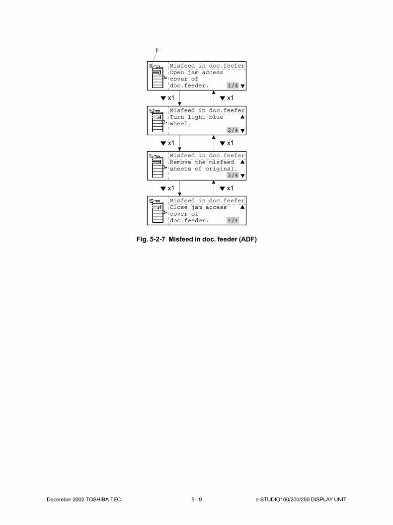
December 2002 TOSHIBA TEC 5 - 9 e-STUDIO160/200/250 DISPLAY UNIT
Fig. 5-2-7 Misfeed in doc. feeder (ADF)
F
x1 x1
x1 x1
x1 x1
Misfeed in doc.feeferOpen jam accesscover ofdoc.feeder. 1/4
Misfeed in doc.feeferTurn light bluewheel.
2/4
Misfeed in doc.feeferRemove the misfeedsheets of original.
3/4
Misfeed in doc.feeferClose jam accesscover ofdoc.feeder. 4/4

e-STUDIO160/200/250 DISPLAY UNIT 5 - 10 December 2002 TOSHIBA TEC
Misfeed in finisherExamine stapler.
2/6
Fig. 5-2-8 Misfeed in finisher (Finisher)
G
x1 x1
x1 x1
x1 x1
x1 x1
x1 x1
Misfeed in finisherMove finisher awayfrom copier.
1/6
Misfeed in finisherRemove any misfeedpaper fromfinisher. 2/6
Misfeed in finisherJoin finisherto copier.
3/6
Misfeed in finisherOpen bridge cover.
4/6
Misfeed in finisherRemove any misfeedpaper frombridge. 5/6
Misfeed in finisherClose bridge cover.
6/6
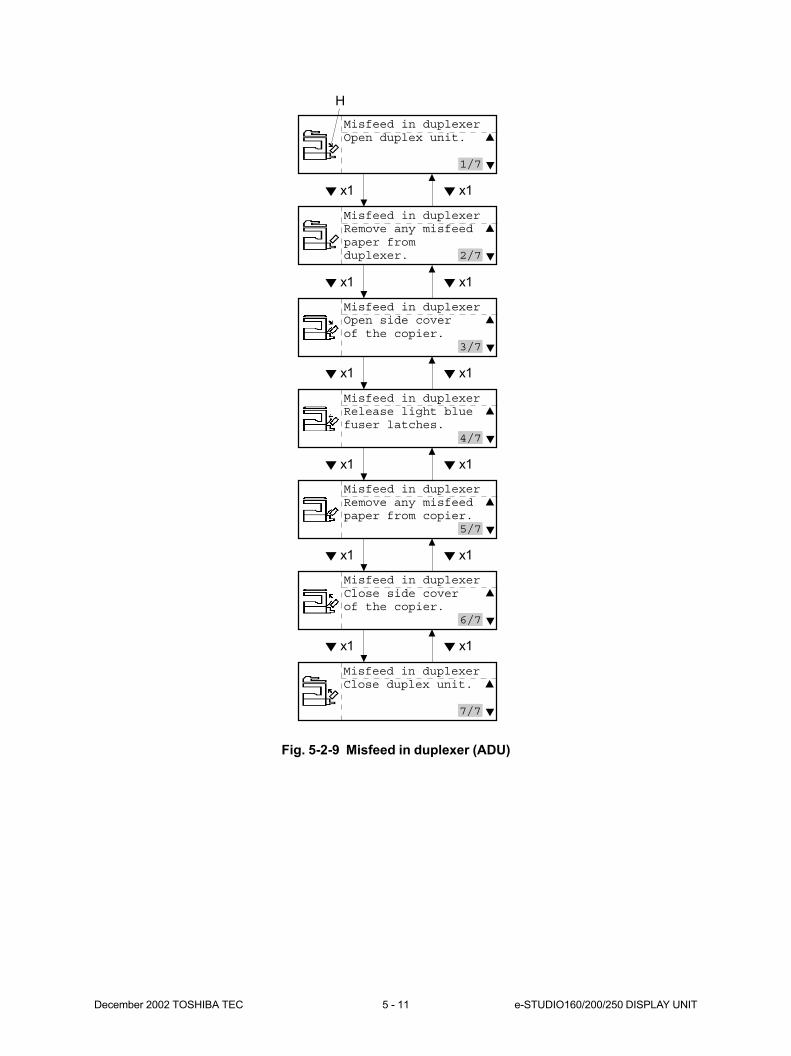
December 2002 TOSHIBA TEC 5 - 11 e-STUDIO160/200/250 DISPLAY UNIT
Fig. 5-2-9 Misfeed in duplexer (ADU)
H
x1 x1
x1 x1
x1 x1
x1 x1
x1 x1
x1 x1
Misfeed in duplexerOpen duplex unit.
1/7
Misfeed in duplexerRemove any misfeedpaper fromduplexer. 2/7
Misfeed in duplexerOpen side coverof the copier.
3/7
Misfeed in duplexerRelease light bluefuser latches.
4/7
Misfeed in duplexerRemove any misfeedpaper from copier.
5/7
Misfeed in duplexerClose side coverof the copier.
6/7
Misfeed in duplexerClose duplex unit.
7/7
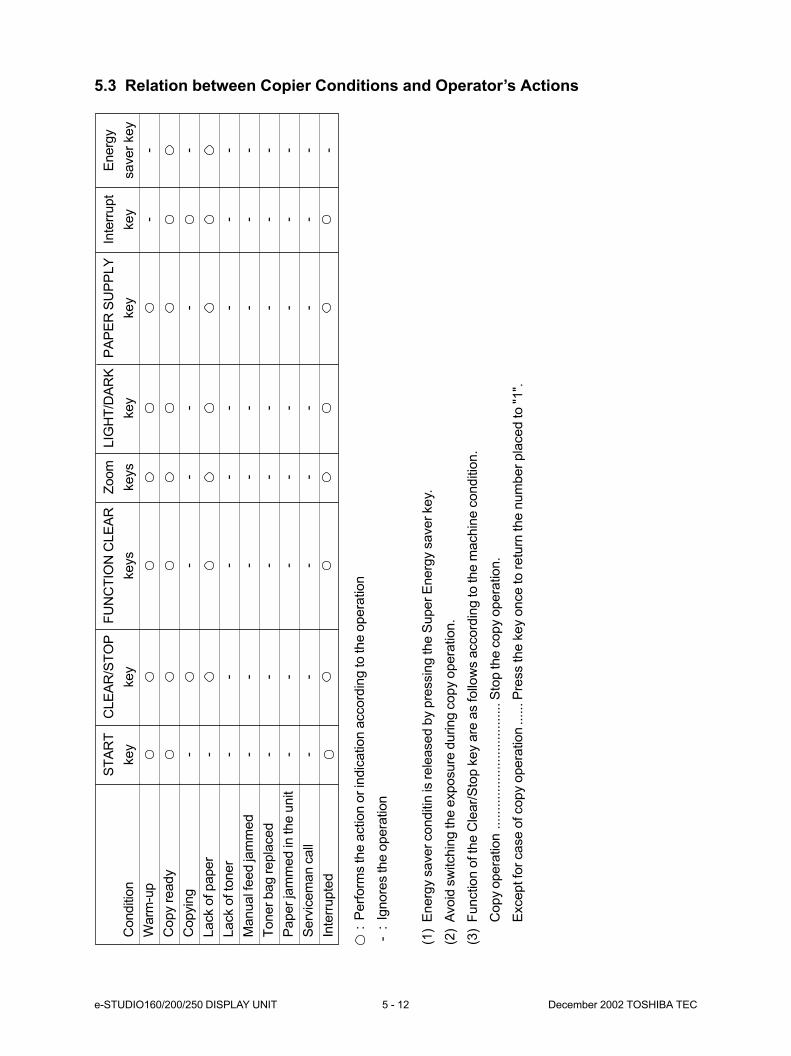
e-STUDIO160/200/250 DISPLAY UNIT 5 - 12 December 2002 TOSHIBA TEC
5.3 Relation between Copier Conditions and Operator’s Actions
Conditio
n
Warm
-up
Copy r
eady
Copyin
g
Lack o
f paper
Lack o
f to
ner
Manual f
eed ja
mm
ed
Toner
bag r
epla
ced
Paper
jam
med in
the u
nit
Serv
icem
an c
all
Inte
rrupte
d
ST
AR
T
key - - - - - - -
CLE
AR
/ST
OP
key - - - - -
FU
NC
TIO
N C
LE
AR
keys
- - - - - -
Zoom
keys
- - - - - -
LIG
HT
/DA
RK
key - - - - - -
PA
PE
R S
UP
PLY
key - - - - - -
Inte
rrupt
key - - - - - -
Energ
y
saver
key
- - - - - - - -
:P
erf
orm
s the a
ction o
r in
dic
ation a
ccord
ing to the o
pera
tion
-:
Ignore
s the o
pera
tion
(1)
Energ
y s
aver
conditin
is r
ele
ased b
y p
ressin
g the S
uper
Energ
y s
aver
key.
(2)
Avoid
sw
itchin
g the e
xposure
during c
opy o
pera
tion.
(3)
Function o
f th
e C
lear/
Sto
p k
ey a
re a
s follo
ws a
ccord
ing to the m
achin
e c
onditio
n.
Copy o
pera
tion
..................................
Sto
p the c
opy o
pera
tion.
Except fo
r case o
f copy o
pera
tion
......
Pre
ss the k
ey o
nce to r
etu
rn the n
um
ber
pla
ced to "
1".
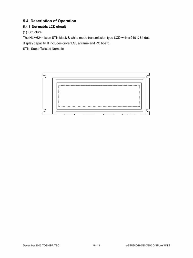
December 2002 TOSHIBA TEC 5 - 13 e-STUDIO160/200/250 DISPLAY UNIT
5.4 Description of Operation
5.4.1 Dot matrix LCD circuit
(1) Structure
The HLM6244 is an STN black & white mode transmission type LCD with a 240 X 64 dots
display capacity. It includes driver LSI, a frame and PC board.
STN: Super Twisted Nematic

e-STUDIO160/200/250 DISPLAY UNIT 5 - 14 December 2002 TOSHIBA TEC
(2) Block diagram
FLM
VSSVDD
VO
VEE
LP
SCP
D
Ydriver
LCD240 x 64 dots
Coml
Com64 Segl
X driver 1
AC signalgenerating circuit
X driver 2 X driver 3
Seg240
BIAS
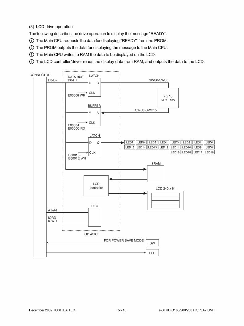
December 2002 TOSHIBA TEC 5 - 15 e-STUDIO160/200/250 DISPLAY UNIT
LATCH
D
CLK7 x 16
KEY SW
E00008 WR
Q
BUFFER
Y
LED7
LED15
LED6
LED14
LED5
LED13
LED4
LED12
LED3
LED11
LED2
LED10
LED1
LED9
LED0
LED8
LED19 LED18 LED17 LED16
CLKE0000AE0000C RD
DATA BUSD0-D7D0-D7
A1-A4
IORDIOWR
FOR POWER SAVE MODE
SWS0-SWS6
SWC0-SWC15A
LATCH
DEC
SW
LED
CONNECTOR
OP ASIC
SRAM
LCD 240 x 64LCD
controller
D
CLKE00010-E0001E WR
Q
(3) LCD drive operation
The following describes the drive operation to display the message “READY”.
The Main CPU requests the data for displaying “READY” from the PROM.
The PROM outputs the data for displaying the message to the Main CPU.
The Main CPU writes to RAM the data to be displayed on the LCD.
The LCD controller/driver reads the display data from RAM, and outputs the data to the LCD.
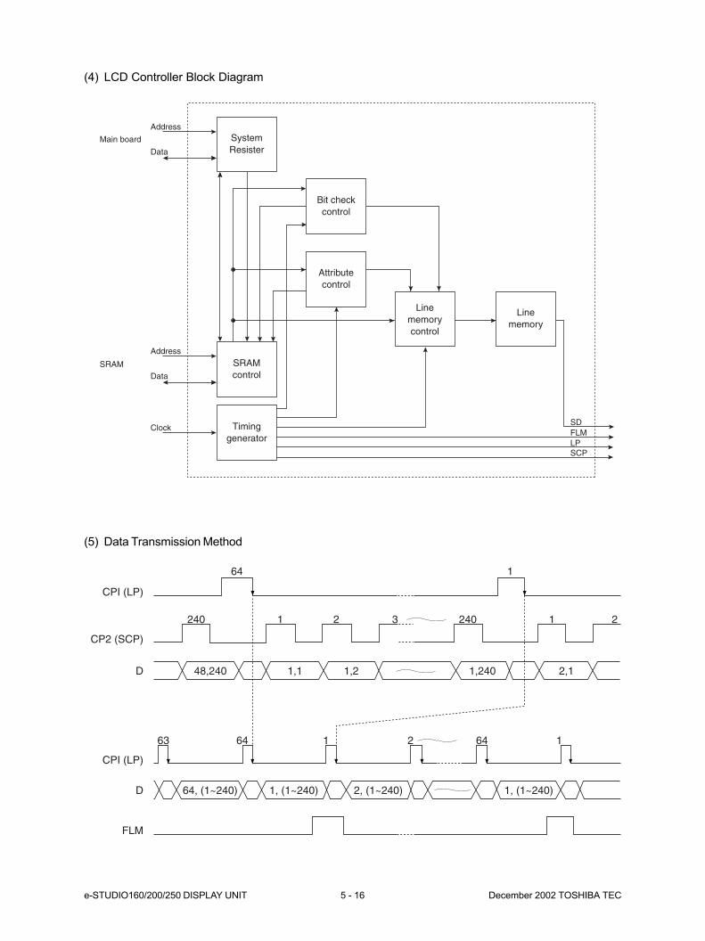
e-STUDIO160/200/250 DISPLAY UNIT 5 - 16 December 2002 TOSHIBA TEC
(4) LCD Controller Block Diagram
(5) Data Transmission Method
SystemResister
Address
Main board
SRAM
Data
Address
FLMSD
LPSCP
Clock
Data
SRAMcontrol
Timinggenerator
Bit checkcontrol
Attributecontrol
Linememorycontrol
Linememory
CPI (LP)
64 1
FLM
240
48,240 1,1 1,2 1,240 2,1
1 2 3 240 1 2
CP2 (SCP)
CPI (LP)
D
64, (1~240) 1, (1~240) 2, (1~240) 1, (1~240)D
63 64 641 2 1
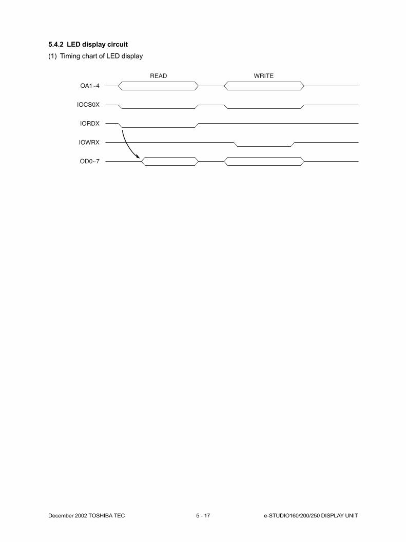
December 2002 TOSHIBA TEC 5 - 17 e-STUDIO160/200/250 DISPLAY UNIT
5.4.2 LED display circuit
(1) Timing chart of LED display
OA1~4
IOCS0X
READ WRITE
IORDX
IOWRX
OD0~7
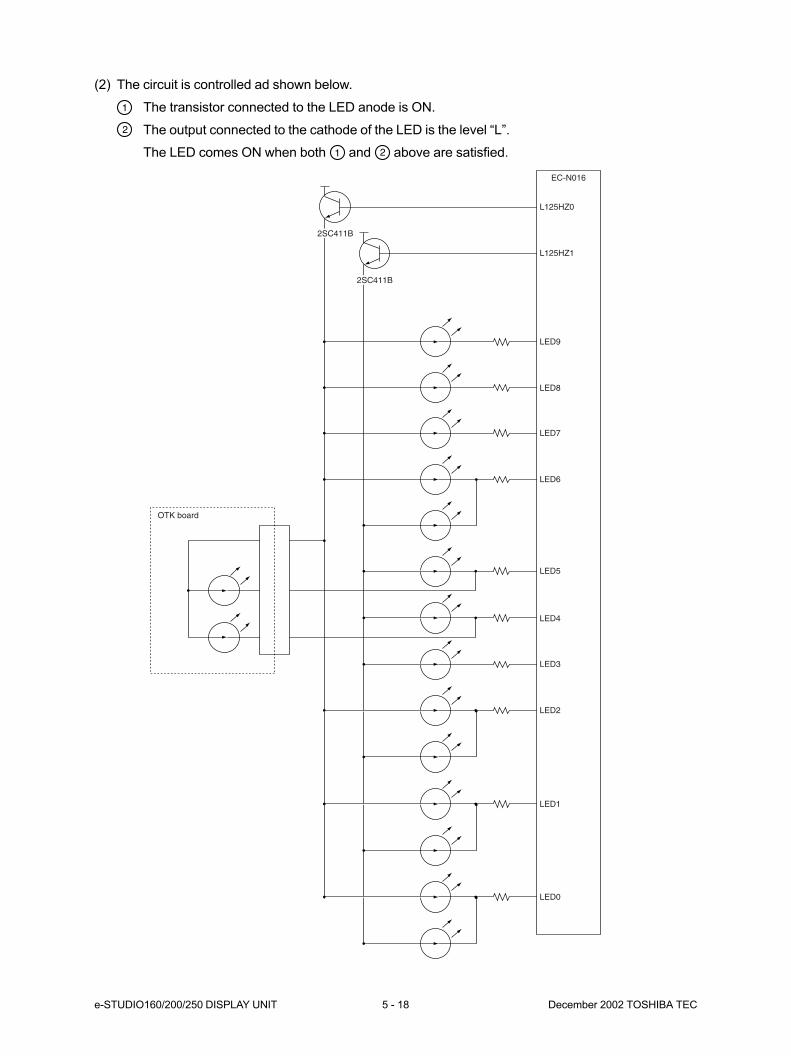
e-STUDIO160/200/250 DISPLAY UNIT 5 - 18 December 2002 TOSHIBA TEC
(2) The circuit is controlled ad shown below.
The transistor connected to the LED anode is ON.
The output connected to the cathode of the LED is the level “L”.
The LED comes ON when both and above are satisfied.
2SC411B
OTK board
2SC411B
L125HZ0
EC-N016
L125HZ1
LED9
LED8
LED7
LED6
LED5
LED4
LED3
LED2
LED1
LED0
6. IMAGE PROCESSING ............................. 6-1
6.1 Introduction ............................................................................................... 6-1
6.2 Image Processing Circuit .......................................................................... 6-2
6.3 SLG Board ................................................................................................ 6-3
6.3.1 Features ....................................................................................... 6-3
6.3.2 Functions of the image processing circuit .................................... 6-3
6.4 Scanner .................................................................................................... 6-7
6.5 Printer ....................................................................................................... 6-8
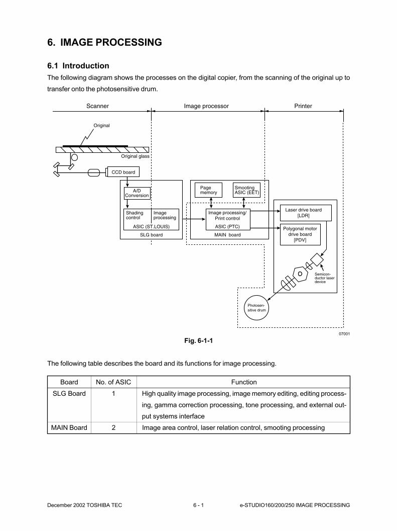
December 2002 TOSHIBA TEC 6 - 1 e-STUDIO160/200/250 IMAGE PROCESSING
6. IMAGE PROCESSING
6.1 Introduction
The following diagram shows the processes on the digital copier, from the scanning of the original up to
transfer onto the photosensitive drum.
Fig. 6-1-1
The following table describes the board and its functions for image processing.
Original
Image processor PrinterScanner
Original glass
Shadingcontrol
A/DConversion
Imageprocessing
MAIN board
Laser drive board[LDR]
Polygonal motordrive board
[PDV]
Semicon-ductor laserdevice
Photosen-sitive drum
CCD board
ASIC (ST.LOUIS)
SLG board
Pagememory
SmootingASIC (EET)
Image processing/Print control
ASIC (PTC)
07001
Board No. of ASIC Function
SLG Board 1 High quality image processing, image memory editing, editing process-
ing, gamma correction processing, tone processing, and external out-
put systems interface
MAIN Board 2 Image area control, laser relation control, smooting processing
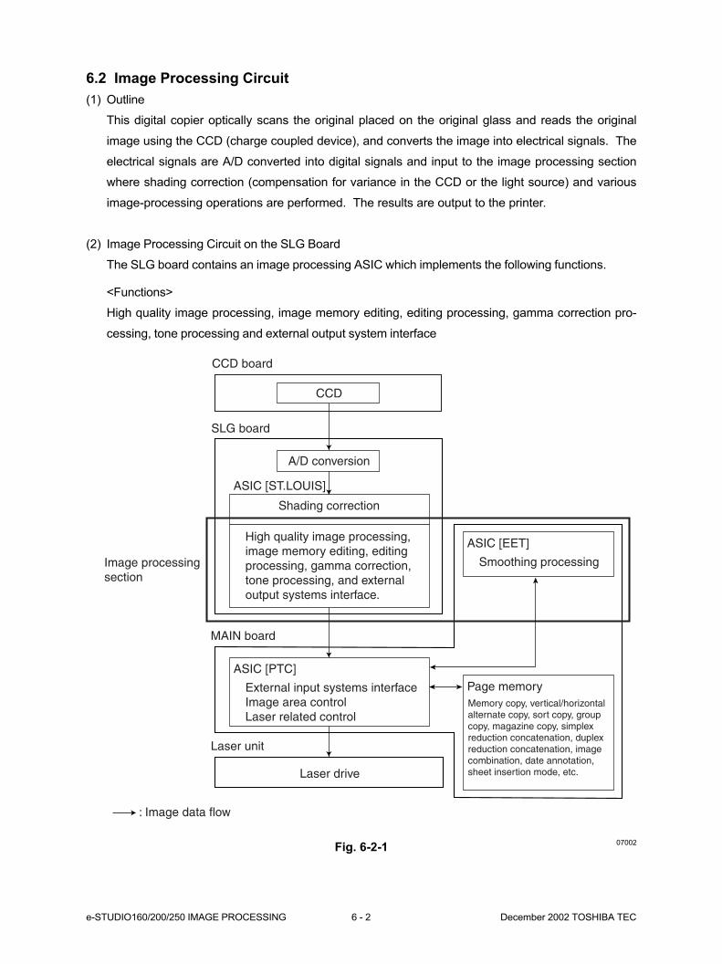
e-STUDIO160/200/250 IMAGE PROCESSING 6 - 2 December 2002 TOSHIBA TEC
Fig. 6-2-107002
CCD board
CCD
A/D conversion
SLG board
Image processingsection
Shading correction
High quality image processing,image memory editing, editingprocessing, gamma correction,tone processing, and externaloutput systems interface.
MAIN board
Laser unit
Laser drive
: Image data flow
External input systems interfaceImage area controlLaser related control
ASIC [ST.LOUIS]
ASIC [PTC]
Smoothing processing
ASIC [EET]
Page memoryMemory copy, vertical/horizontal alternate copy, sort copy, group copy, magazine copy, simplex reduction concatenation, duplex reduction concatenation, image combination, date annotation, sheet insertion mode, etc.
6.2 Image Processing Circuit
(1) Outline
This digital copier optically scans the original placed on the original glass and reads the original
image using the CCD (charge coupled device), and converts the image into electrical signals. The
electrical signals are A/D converted into digital signals and input to the image processing section
where shading correction (compensation for variance in the CCD or the light source) and various
image-processing operations are performed. The results are output to the printer.
(2) Image Processing Circuit on the SLG Board
The SLG board contains an image processing ASIC which implements the following functions.
<Functions>
High quality image processing, image memory editing, editing processing, gamma correction pro-
cessing, tone processing and external output system interface
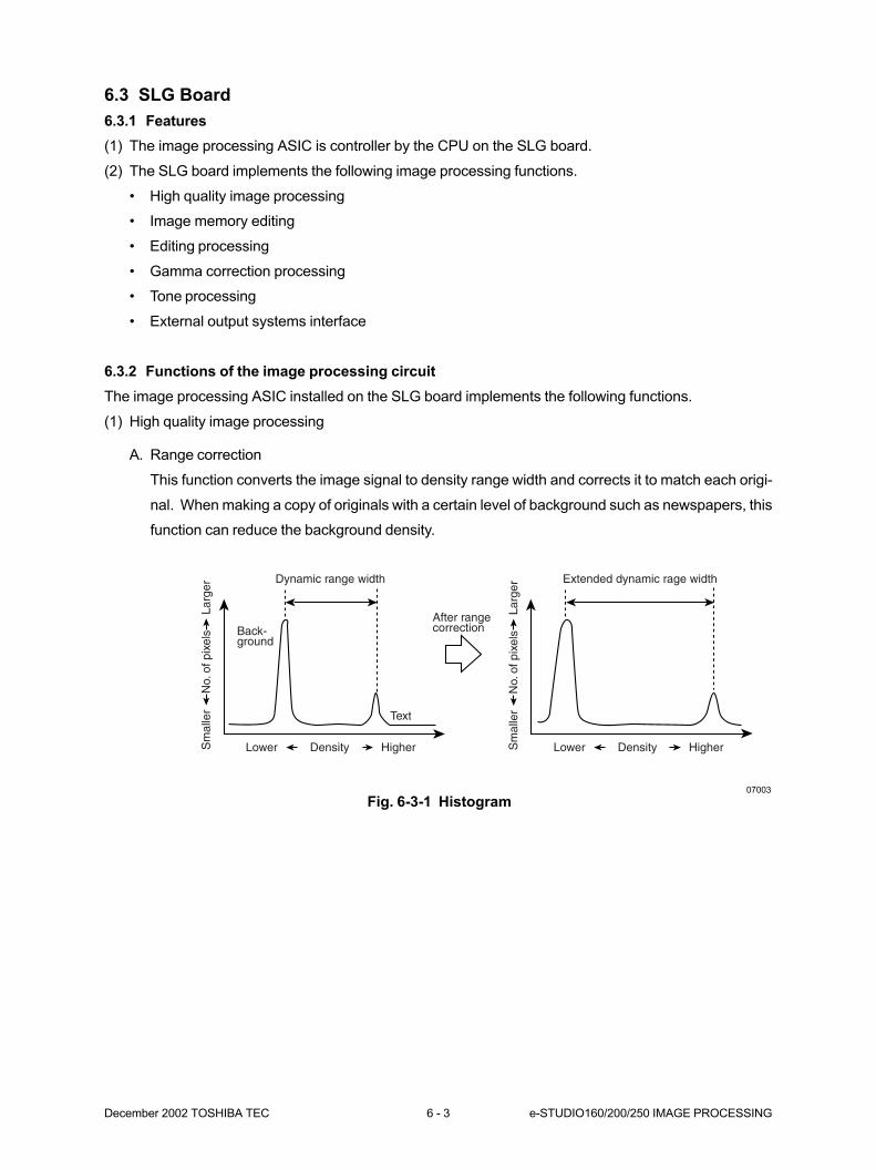
December 2002 TOSHIBA TEC 6 - 3 e-STUDIO160/200/250 IMAGE PROCESSING
6.3 SLG Board
6.3.1 Features
(1) The image processing ASIC is controller by the CPU on the SLG board.
(2) The SLG board implements the following image processing functions.
• High quality image processing
• Image memory editing
• Editing processing
• Gamma correction processing
• Tone processing
• External output systems interface
6.3.2 Functions of the image processing circuit
The image processing ASIC installed on the SLG board implements the following functions.
(1) High quality image processing
A. Range correction
This function converts the image signal to density range width and corrects it to match each origi-
nal. When making a copy of originals with a certain level of background such as newspapers, this
function can reduce the background density.
Fig. 6-3-1 Histogram
Dynamic range width Extended dynamic rage width
Back-ground
After rangecorrection
Text
Sm
alle
rN
o. o
f pix
els
Larg
er
Lower Density Higher Lower Density HigherSm
alle
rN
o. o
f pix
els
Larg
er
07003
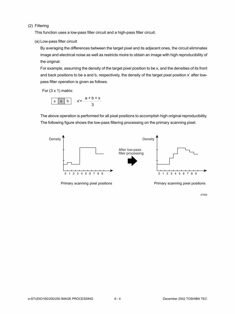
e-STUDIO160/200/250 IMAGE PROCESSING 6 - 4 December 2002 TOSHIBA TEC
(2) Filtering
This function uses a low-pass filter circuit and a high-pass filter circuit.
(a) Low-pass filter circuit
By averaging the differences between the target pixel and its adjacent ones, the circuit eliminates
image and electrical noise as well as restricts moire to obtain an image with high reproducibility of
the original.
For example, assuming the density of the target pixel position to be x, and the densities of its front
and back positions to be a and b, respectively, the density of the target pixel position x’ after low-
pass filter operation is given as follows.
For (3 x 1) matrix:
The above operation is performed for all pixel positions to accomplish high original reproducibility.
The following figure shows the low-pass filtering processing on the primary scanning pixel.
07005
0 1 2 3 4 5 6 7 8 9 0 1 2 3 4 5 6 7 8 9
Density Density
After low-passfilter processing
Primary scanning pixel positions Primary scanning pixel positions
a + b + x
3a x b x’=
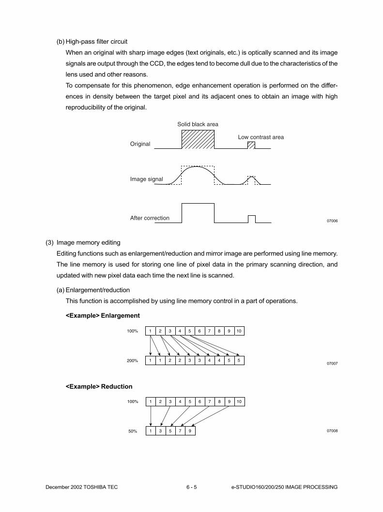
December 2002 TOSHIBA TEC 6 - 5 e-STUDIO160/200/250 IMAGE PROCESSING
(b) High-pass filter circuit
When an original with sharp image edges (text originals, etc.) is optically scanned and its image
signals are output through the CCD, the edges tend to become dull due to the characteristics of the
lens used and other reasons.
To compensate for this phenomenon, edge enhancement operation is performed on the differ-
ences in density between the target pixel and its adjacent ones to obtain an image with high
reproducibility of the original.
(3) Image memory editing
Editing functions such as enlargement/reduction and mirror image are performed using line memory.
The line memory is used for storing one line of pixel data in the primary scanning direction, and
updated with new pixel data each time the next line is scanned.
(a) Enlargement/reduction
This function is accomplished by using line memory control in a part of operations.
<Example> Enlargement
Solid black area
Original
Image signal
After correction
Low contrast area
<Example> Reduction
1100%
200%
2 3 4 5 6 7 8 9 10
1 1 2 2 3 3 4 4 5 5
1100%
50%
2 3 4 5 6 7 8 9 10
1 3 5 7 9
07006
07007
07008
e-STUDIO160/200/250 IMAGE PROCESSING 6 - 6 December 2002 TOSHIBA TEC
(b) Mirror image
This function reverses the right side and the left side in the primary scanning direction of the
original and outputs this reversed image.
(4) Editing processing
This function reverses image data from negative to positive or vice versa on the entire area.
(5) Gamma correction
This function corrects input/output characteristics of the scanner/printer to obtain image signals hav-
ing input/output characteristics suitable for the copy mode.
(6) Tone processing
This function processes tone to faithfully reproduce halftone images such as photographs.
(7) External output systems interface
This function controls output interface of the MAIN board.

December 2002 TOSHIBA TEC 6 - 7 e-STUDIO160/200/250 IMAGE PROCESSING
6.4 Scanner
Light reflected from the original surface is picked up by the CCD (Charge Coupled Device) where photo-
voltaic conversion is carried out. By photo-voltaic conversion, optical image data are converted to electri-
cal signals. These analog electrical signals are then converted to digital signals by A/D conversion, and
the required image processing is carried out on these digital signals.
(1) Photo-voltaic conversion
Optical signals from the original are converted to electrical signals by the CCD device. For details, see
Chapter 7, 6-1.
(2) Signal amplification
After conversion by the CCD, the electrical signals are amplified.
(3) A/D conversion
Analog signals are converted to digital signals.
(4) Shading correction
The signals picked up by the CCD device are compensated. For details, see Chapter 7, 6-2.
To next stageCCDSignal
amplification
A/D
conversion
Shading
compensation

e-STUDIO160/200/250 IMAGE PROCESSING 6 - 8 December 2002 TOSHIBA TEC
6.5 Printer
Image signals processed on the Main board are processed on the print-control ASIC and the laser drive
board on the same Main board. Then, they are laser-controlled for the write operation.
(1) Setting of effective image area................ • The top, bottom, left and right margins are set.
(2) Synchronization Clock Generation .......... • HSYNC and the reference clock signal at printer block
block of horizontal synchronizing synchronized with the signal.
signal (HSYNC)
(3) Laser drive block .................................... • ON/OFF control of the semiconductor laser and APC (Auto
Power Control) control.
7. SCANNER ................................................ 7-1
7.1 Functions .................................................................................................. 7-1
7.2 Configuration ............................................................................................ 7-2
7.3 Scanner Motor Operation.......................................................................... 7-5
7.4 Scanner Motor Drive Circuit ...................................................................... 7-6
7.5 Exposure Lamp Control ............................................................................ 7-9
7.5.1 Exposure lamp ............................................................................. 7-9
7.5.2 Exposure Lamp Control Circuit .................................................... 7-10
7.6 General Description of CCD control .......................................................... 7-12
7.6.1 Photo-voltaic conversion .............................................................. 7-12
7.6.2 Shading compensation ................................................................. 7-13
7.7 Automatic Original-Size Detection Circuit (e-STUDIO200/250 series)...... 7-14
7.7.1 Principle of original-size detection ................................................ 7-14
7.7.2 Original size detection .................................................................. 7-14
7.8 Damp Heater Control Circuit (ASD/AUD/CND/SAD models) .................... 7-17
7.9 Disassembly and Replacement ................................................................ 7-18

December 2002 TOSHIBA TEC 7 - 1 e-STUDIO160/200/250 SCANNER
7. SCANNER7.1 Functions
In this copier's scanner, light is directed at the surface of the original, and the light reflected from the
original projects to the CCD (Charge Coupled Device) by means of mirrors, lens and a slit. Photo-voltaic
conversion by this CCD converts optical image data to electrical signals. These resultant analog signals
undergo A/D conversion to be converted to digital signals. These digital signals undergo various com-
pensation processes to create the required image. These digital signals are computed and processed,
and then sent to the printer.
Carriage 1 rail
Carriage 2 railCarriage 2 Lens
CCD PWA
Scanner control PWA
Scanner drive gear
Scanner motor pulley
Carriage 1
Exposure lamp (Xenon)Reflector
Original glass
08-01-01
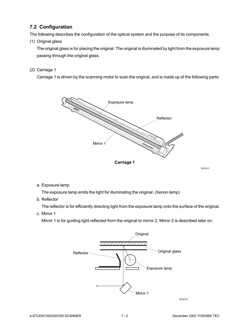
e-STUDIO160/200/250 SCANNER 7 - 2 December 2002 TOSHIBA TEC
7.2 Configuration
The following describes the configuration of the optical system and the purpose of its components.
(1) Original glass
The original glass is for placing the original. The original is illuminated by light from the exposure lamp
passing through the original glass.
(2) Carriage 1
Carriage 1 is driven by the scanning motor to scan the original, and is made up of the following parts:
a. Exposure lamp
The exposure lamp emits the light for illuminating the original. (Xenon lamp)
b. Reflector
The reflector is for efficiently directing light from the exposure lamp onto the surface of the original.
c. Mirror 1
Mirror 1 is for guiding light reflected from the original to mirror 2. Mirror 2 is described later on.
Original
Original glass
Exposure lamp
Mirror 1
Reflector
08-02-02
Carriage 1
08-02-01
Exposure lamp
Mirror 1
Reflector
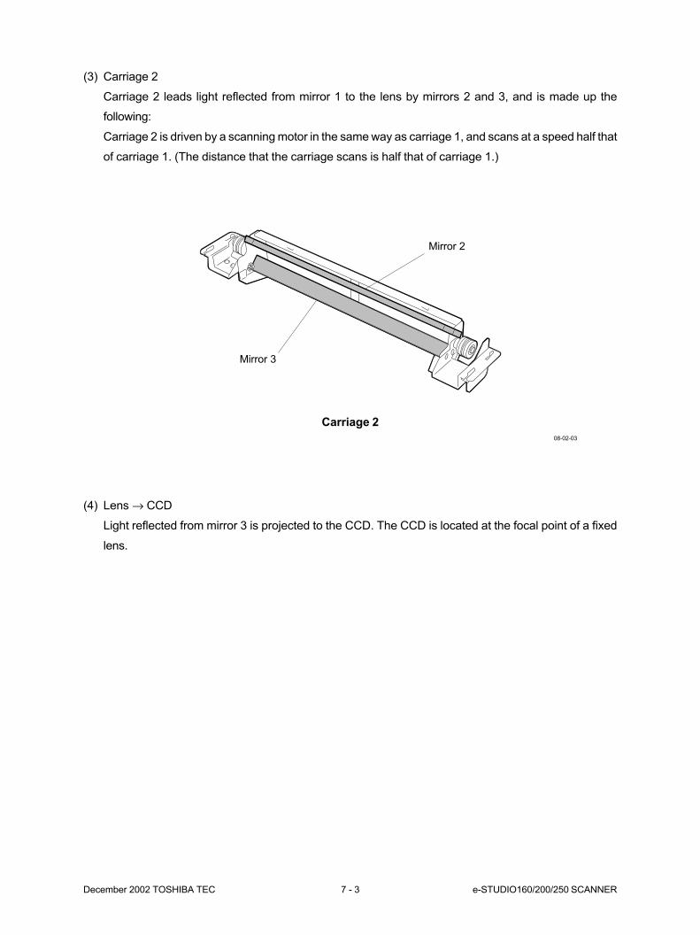
December 2002 TOSHIBA TEC 7 - 3 e-STUDIO160/200/250 SCANNER
(3) Carriage 2
Carriage 2 leads light reflected from mirror 1 to the lens by mirrors 2 and 3, and is made up the
following:
Carriage 2 is driven by a scanning motor in the same way as carriage 1, and scans at a speed half that
of carriage 1. (The distance that the carriage scans is half that of carriage 1.)
(4) Lens → CCD
Light reflected from mirror 3 is projected to the CCD. The CCD is located at the focal point of a fixed
lens.
Carriage 2
08-02-03
Mirror 2
Mirror 3
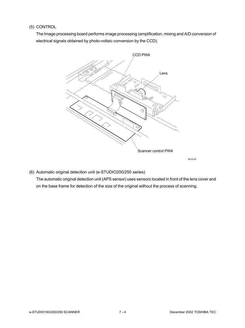
e-STUDIO160/200/250 SCANNER 7 - 4 December 2002 TOSHIBA TEC
(5) CONTROL
The Image processing board performs image processing (amplification, mixing and A/D conversion of
electrical signals obtained by photo-voltaic conversion by the CCD).
(6) Automatic original detection unit (e-STUDIO200/250 series)
The automatic original detection unit (APS sensor) uses sensors located in front of the lens cover and
on the base frame for detection of the size of the original without the process of scanning.
Lens
Scanner control PWA
CCD PWA
08-02-04
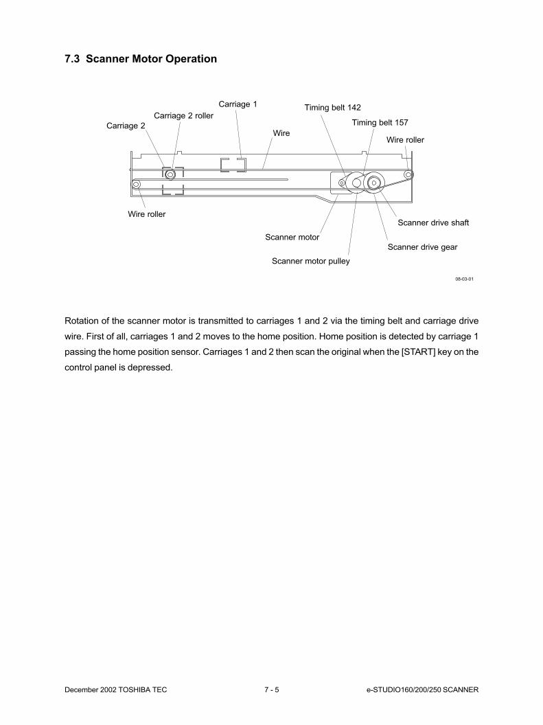
December 2002 TOSHIBA TEC 7 - 5 e-STUDIO160/200/250 SCANNER
7.3 Scanner Motor Operation
Rotation of the scanner motor is transmitted to carriages 1 and 2 via the timing belt and carriage drive
wire. First of all, carriages 1 and 2 moves to the home position. Home position is detected by carriage 1
passing the home position sensor. Carriages 1 and 2 then scan the original when the [START] key on the
control panel is depressed.
Timing belt 157
Wire roller
Scanner motor
Scanner motor pulley
Scanner drive gear
Scanner drive shaftWire roller
Carriage 2
Carriage 2 roller
Carriage 1
Wire
Timing belt 142
08-03-01
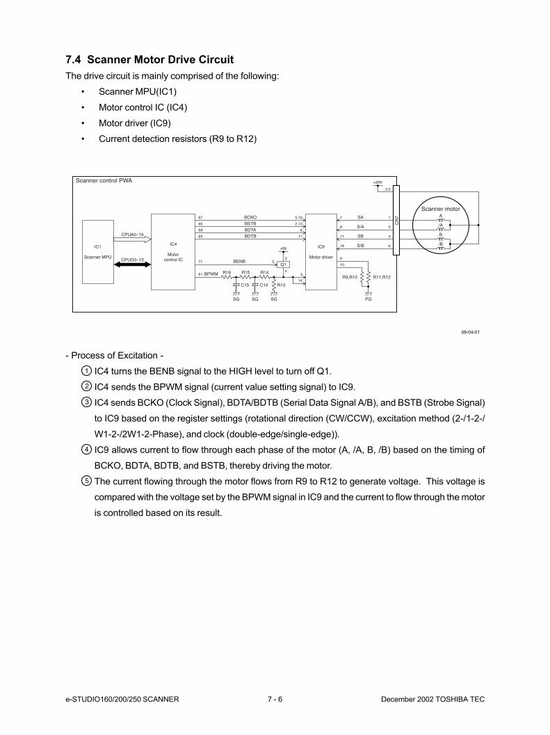
e-STUDIO160/200/250 SCANNER 7 - 6 December 2002 TOSHIBA TEC
7.4 Scanner Motor Drive Circuit
The drive circuit is mainly comprised of the following:
• Scanner MPU(IC1)
• Motor control IC (IC4)
• Motor driver (IC9)
• Current detection resistors (R9 to R12)
IC1
Scanner MPU
IC4
Motorcontrol IC
IC9
Motor driver
Scanner motorA
/A
B
/B
+24V
CN
7
BPWM R16 R15 R14
SG PGSGSG
R13C14C15
CPUA0~19
Scanner control PWA
CPUD0~15
61
BENB71
BDTB69
BDTA68
BSTB60
BCKO67
17
6
2,13
5,16 SA1 1
2,5
S/A8 3
SB11 4
S/B18
R11,R12
9
R9,R10
10
6+5V
2
4
3Q1
3
14
08-04-01
- Process of Excitation -
IC4 turns the BENB signal to the HIGH level to turn off Q1.
IC4 sends the BPWM signal (current value setting signal) to IC9.
IC4 sends BCKO (Clock Signal), BDTA/BDTB (Serial Data Signal A/B), and BSTB (Strobe Signal)
to IC9 based on the register settings (rotational direction (CW/CCW), excitation method (2-/1-2-/
W1-2-/2W1-2-Phase), and clock (double-edge/single-edge)).
IC9 allows current to flow through each phase of the motor (A, /A, B, /B) based on the timing of
BCKO, BDTA, BDTB, and BSTB, thereby driving the motor.
The current flowing through the motor flows from R9 to R12 to generate voltage. This voltage is
compared with the voltage set by the BPWM signal in IC9 and the current to flow through the motor
is controlled based on its result.
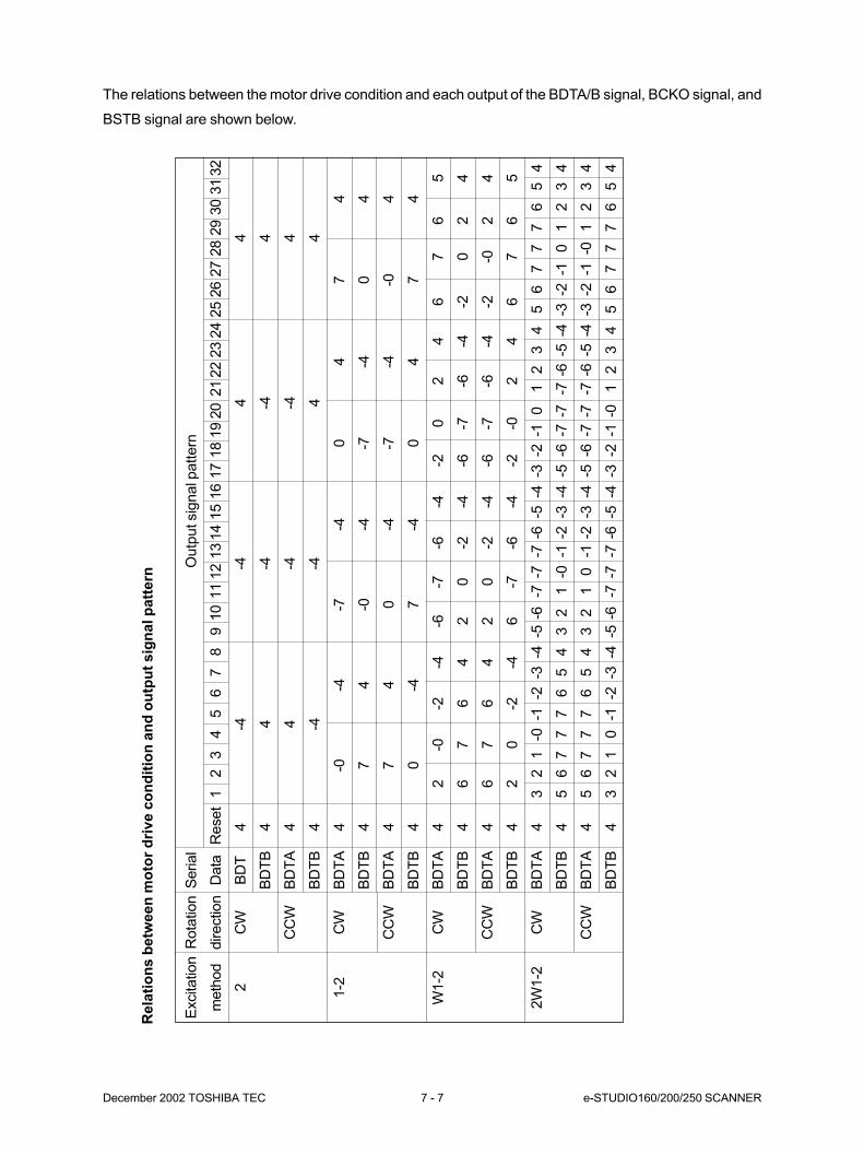
December 2002 TOSHIBA TEC 7 - 7 e-STUDIO160/200/250 SCANNER
The relations between the motor drive condition and each output of the BDTA/B signal, BCKO signal, and
BSTB signal are shown below.
Rela
tio
ns b
etw
een
mo
tor
dri
ve c
on
dit
ion
an
d o
utp
ut
sig
nal p
att
ern
Outp
ut sig
nal p
attern
Reset
12
34
56
78
910
11
12
13
14
15
16
17
18
19
20
21
22
23
24
25
26
27
28
29
30
31
32
4-4
-44
4
44
-4-4
4
44
-4-4
4
4-4
-44
4
4-0
-4-7
-40
47
4
47
4-0
-4-7
-40
4
47
40
-4-7
-4-0
4
40
-47
-40
47
4
42
-0-2
-4-6
-7-6
-4-2
02
46
76
5
46
76
42
0-2
-4-6
-7-6
-4-2
02
4
46
76
42
0-2
-4-6
-7-6
-4-2
-02
4
42
0-2
-46
-7-6
-4-2
-02
46
76
5
43
21
-0-1
-2-3
-4-5
-6-7
-7-7
-6-5
-4-3
-2-1
01
23
45
67
77
65
4
45
67
77
65
43
21
-0-1
-2-3
-4-5
-6-7
-7-7
-6-5
-4-3
-2-1
01
23
4
45
67
77
65
43
21
0-1
-2-3
-4-5
-6-7
-7-7
-6-5
-4-3
-2-1
-01
23
4
43
21
0-1
-2-3
-4-5
-6-7
-7-7
-6-5
-4-3
-2-1
-01
23
45
67
77
65
4
Excitation
meth
od
2 1-2
W1-2
2W
1-2
Rota
tion
direction
CW
CC
W
CW
CC
W
CW
CC
W
CW
CC
W
Serial
Data
BD
T
BD
TB
BD
TA
BD
TB
BD
TA
BD
TB
BD
TA
BD
TB
BD
TA
BD
TB
BD
TA
BD
TB
BD
TA
BD
TB
BD
TA
BD
TB
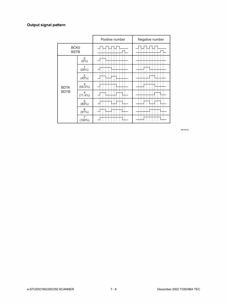
e-STUDIO160/200/250 SCANNER 7 - 8 December 2002 TOSHIBA TEC
BCK0BSTB
Positive number Negative number
BDTABDTB
0(0%)
1(20%)
2(40%)
3(55.5%)
4(71.4%)
5(83%)
6(91%)
7(100%)
08-04-02
Output signal pattern
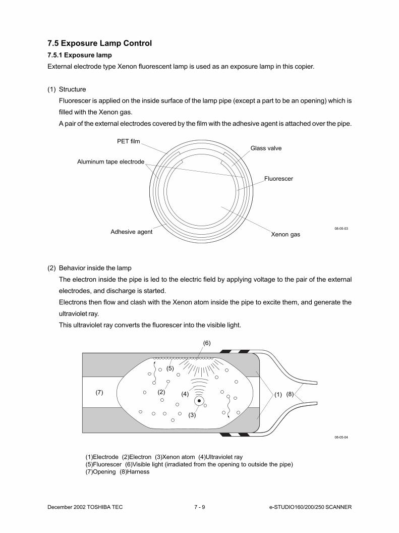
December 2002 TOSHIBA TEC 7 - 9 e-STUDIO160/200/250 SCANNER
7.5 Exposure Lamp Control
7.5.1 Exposure lamp
External electrode type Xenon fluorescent lamp is used as an exposure lamp in this copier.
(1) Structure
Fluorescer is applied on the inside surface of the lamp pipe (except a part to be an opening) which is
filled with the Xenon gas.
A pair of the external electrodes covered by the film with the adhesive agent is attached over the pipe.
(2) Behavior inside the lamp
The electron inside the pipe is led to the electric field by applying voltage to the pair of the external
electrodes, and discharge is started.
Electrons then flow and clash with the Xenon atom inside the pipe to excite them, and generate the
ultraviolet ray.
This ultraviolet ray converts the fluorescer into the visible light.
(1)Electrode (2)Electron (3)Xenon atom (4)Ultraviolet ray
(5)Fluorescer (6)Visible light (irradiated from the opening to outside the pipe)
(7)Opening (8)Harness
PET film
Xenon gas
Fluorescer
Glass valve
Adhesive agent
Aluminum tape electrode
08-05-03
08-05-04
(1) (8)
(6)
(3)
(4)(2)
(5)
(7)

e-STUDIO160/200/250 SCANNER 7 - 10 December 2002 TOSHIBA TEC
7.5.2 Exposure Lamp Control Circuit
This circuit is made up of the motor control IC (IC4), and the transformer, capacitor and other peripheral
elements on the Inverter PWA and controls the lighting of the exposure lamp.
The circuit configurations are different on the e-STUDIO160 series and e-STUDIO200/250 series.
e-STUDIO160 series
The motor control IC (IC4) turns the LAMP signal to the HIGH level.
The transistor (Q3) turns on and the LAMP signal turns to the GND level.
The transistor (Q3) on the Inverter PWA turns on to apply +24V to the Inverter PWA.
The transistors (Q1, Q2) are biased by the starting resistors (R1, R2). At this time, either of Q1
and Q2 turns on due to the transistor characteristics.
The following explains a case where Q1 has turned on.
If Q2 has turned on, Q1 and Q2 should be substituted for each other.
Bias voltage of Q1 is produced in the Nb winding of the transformer (T1) to allow Q1 to completely
turn on. At this time, Q2 turns off because it is reverse biased.
When current flows through T1, the primary circuit resonates due to the Np winding and capacitor
(C1). This causes the bias voltage of the Nb winding to be reversed.
Q1 turns off due to the reverse bias voltage and Q2 turns on.
As Q1 and Q2 turn on and off alternately in this way, high-frequency voltage is produced in the
primary circuit of T1. This voltage is boosted by the Np winding and Ns winding and supplied to
the exposure lamp for lighting.
08-05-01
IC1
Scanner MPU
Exposure lamp
IC4
Motorcontrol IC
CN
2
PG PG
CPUA0~19
Scanner control PWA Inverter PWA
CPUD0~15
LAMP58
+24V
ICP1
Q3
Q3
Q1
R1
C1
Np
T1
Nb
NsR2
Q2
2
1 1
4
3
2
1
3
CN
1
CN
2
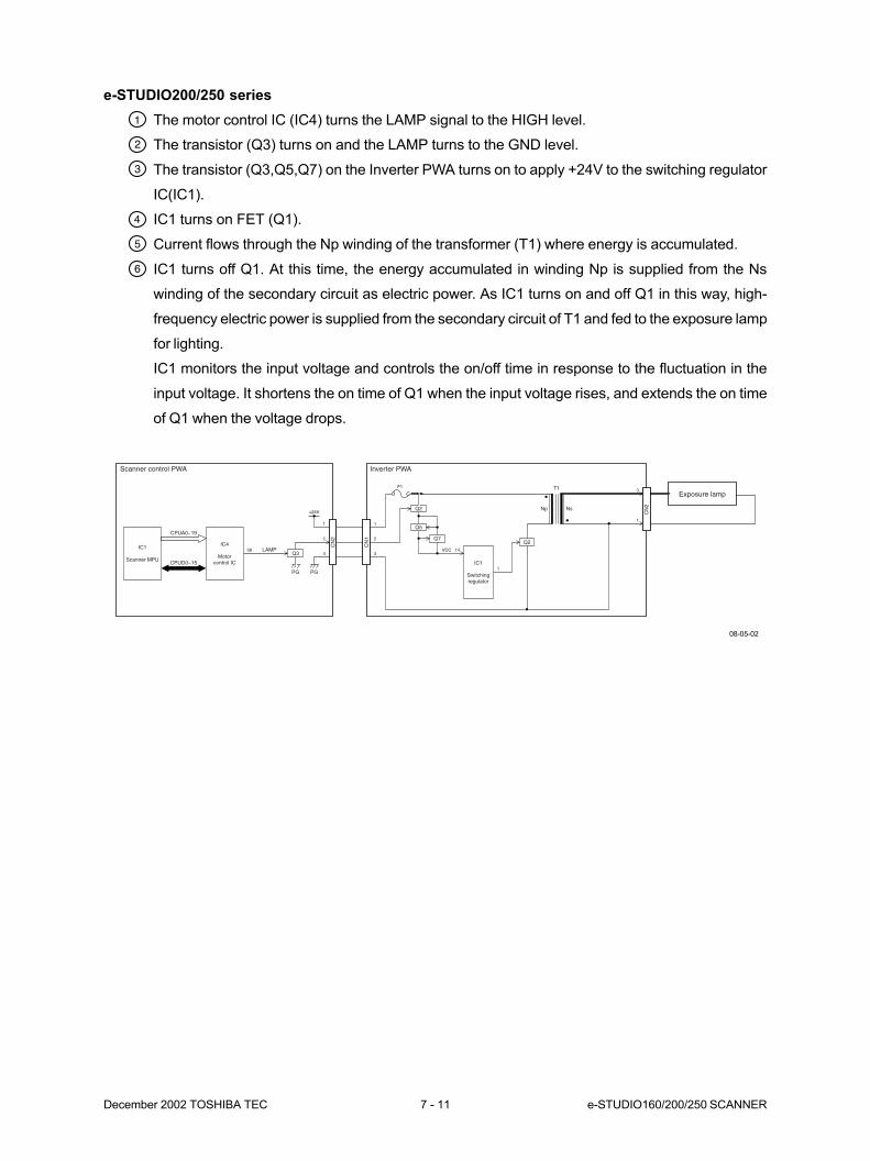
December 2002 TOSHIBA TEC 7 - 11 e-STUDIO160/200/250 SCANNER
e-STUDIO200/250 series
The motor control IC (IC4) turns the LAMP signal to the HIGH level.
The transistor (Q3) turns on and the LAMP turns to the GND level.
The transistor (Q3,Q5,Q7) on the Inverter PWA turns on to apply +24V to the switching regulator
IC(IC1).
IC1 turns on FET (Q1).
Current flows through the Np winding of the transformer (T1) where energy is accumulated.
IC1 turns off Q1. At this time, the energy accumulated in winding Np is supplied from the Ns
winding of the secondary circuit as electric power. As IC1 turns on and off Q1 in this way, high-
frequency electric power is supplied from the secondary circuit of T1 and fed to the exposure lamp
for lighting.
IC1 monitors the input voltage and controls the on/off time in response to the fluctuation in the
input voltage. It shortens the on time of Q1 when the input voltage rises, and extends the on time
of Q1 when the voltage drops.
IC1
Scanner MPU
Exposure lamp
IC4
Motorcontrol IC IC1
Switchingregulator
CN
2
PG PG
CPUA0~19
Scanner control PWA Inverter PWA
CPUD0~15
LAMP58
+24V
F1
VCCQ3
Q2
Q5
2
1
3
1
3
2
1
314
1
Q2
CN
1
CN
2
Np Ns
T1
Q7
08-05-02
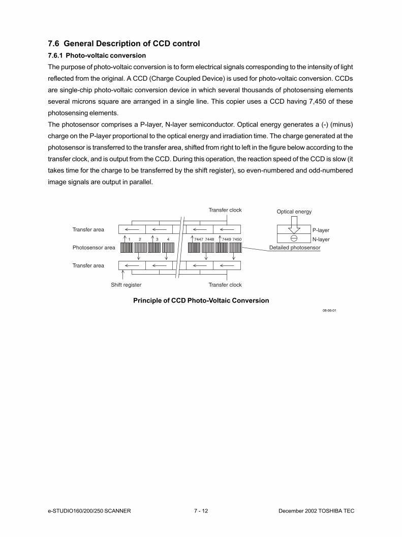
e-STUDIO160/200/250 SCANNER 7 - 12 December 2002 TOSHIBA TEC
7.6 General Description of CCD control
7.6.1 Photo-voltaic conversion
The purpose of photo-voltaic conversion is to form electrical signals corresponding to the intensity of light
reflected from the original. A CCD (Charge Coupled Device) is used for photo-voltaic conversion. CCDs
are single-chip photo-voltaic conversion device in which several thousands of photosensing elements
several microns square are arranged in a single line. This copier uses a CCD having 7,450 of these
photosensing elements.
The photosensor comprises a P-layer, N-layer semiconductor. Optical energy generates a (-) (minus)
charge on the P-layer proportional to the optical energy and irradiation time. The charge generated at the
photosensor is transferred to the transfer area, shifted from right to left in the figure below according to the
transfer clock, and is output from the CCD. During this operation, the reaction speed of the CCD is slow (it
takes time for the charge to be transferred by the shift register), so even-numbered and odd-numbered
image signals are output in parallel.
1 2 3 4 7447 7448 7449 7450
Transfer area
Transfer area
Photosensor area
Transfer clock Optical energy
Detailed photosensor
P-layer
N-layer
Transfer clockShift register
08-06-01
Principle of CCD Photo-Voltaic Conversion
December 2002 TOSHIBA TEC 7 - 13 e-STUDIO160/200/250 SCANNER
7.6.2 Shading compensation
The following problems effect the voltage values obtained by photo-voltaic conversion by the CCD:
As a light distribution of light source is varied.
The reflected light is collected by a lens (the light path is shortest at the CCD center and longest
at the ends), there is a difference in the intensities of light reaching the CCD.
The photo-voltaic capacities of each of the 7,450 CCD elements are uneven.
Consequently, these problems must be compensated. This is called “shading compensation.” Shad-
ing compensation involves normalizing optical energy according to the following equation based
on already known scanned black data and white data, and compensating for uneven illuminance
of the image data and device unevenness.
I = k x
where,
k: Coefficient
S: Image data before compensation
K: Black data (in black memory)
W: White data (in white memory)
(S - K)
(W - K)
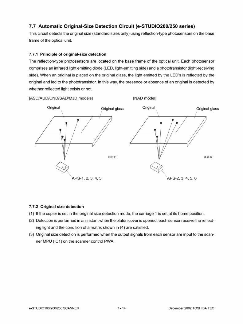
e-STUDIO160/200/250 SCANNER 7 - 14 December 2002 TOSHIBA TEC
7.7 Automatic Original-Size Detection Circuit (e-STUDIO200/250 series)
This circuit detects the original size (standard sizes only) using reflection-type photosensors on the base
frame of the optical unit.
7.7.1 Principle of original-size detection
The reflection-type photosensors are located on the base frame of the optical unit. Each photosensor
comprises an infrared light emitting diode (LED, light-emitting side) and a phototransistor (light-receiving
side). When an original is placed on the original glass, the light emitted by the LED’s is reflected by the
original and led to the phototransistor. In this way, the presence or absence of an original is detected by
whether reflected light exists or not.
[ASD/AUD/CND/SAD/MJD models] [NAD model]
Original Original glass
APS-1, 2, 3, 4, 5
Original Original glass
APS-2, 3, 4, 5, 6
08-07-01 08-07-02
7.7.2 Original size detection
(1) If the copier is set in the original size detection mode, the carriage 1 is set at its home position.
(2) Detection is performed in an instant when the platen cover is opened, each sensor receive the reflect-
ing light and the condition of a matrix shown in (4) are satisfied.
(3) Original size detection is performed when the output signals from each sensor are input to the scan-
ner MPU (IC1) on the scanner control PWA.

December 2002 TOSHIBA TEC 7 - 15 e-STUDIO160/200/250 SCANNER
[ASD/AUD/CND/SAD/MJD models]
[NAD model]
APS-5
APS-4
APS-3
APS-2
APS-1
A3A4
B4
A4-R
B5
B5-R
A5-R
LT-R
LT
LG
APS-6
APS-5
APS-4
APS-3
APS-2
ST-R
LD
08-07-03
08-07-04
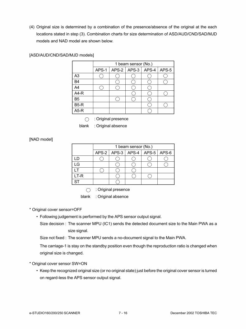
e-STUDIO160/200/250 SCANNER 7 - 16 December 2002 TOSHIBA TEC
(4) Original size is determined by a combination of the presence/absence of the original at the each
locations stated in step (3). Combination charts for size determination of ASD/AUD/CND/SAD/MJD
models and NAD model are shown below.
[ASD/AUD/CND/SAD/MJD models]
[NAD model]
* Original cover sensor=OFF
• Following judgement is performed by the APS sensor output signal.
Size decision : The scanner MPU (IC1) sends the detected document size to the Main PWA as a
size signal.
Size not fixed : The scanner MPU sends a no-document signal to the Main PWA.
The carriage-1 is stay on the standby position even though the reproduction ratio is changed when
original size is changed.
* Original cover sensor SW=ON
• Keep the recognized original size (or no original state) just before the original cover sensor is turned
on regard-less the APS sensor output signal.
APS-2 APS-3 APS-4 APS-5 APS-6
LD
LG
LT
LT-R
ST
1 beam sensor (No.)
1 beam sensor (No.)
: Original presence
blank : Original absence
APS-1 APS-2 APS-3 APS-4 APS-5
A3
B4
A4
A4-R
B5
B5-R
A5-R
: Original presence
blank : Original absence
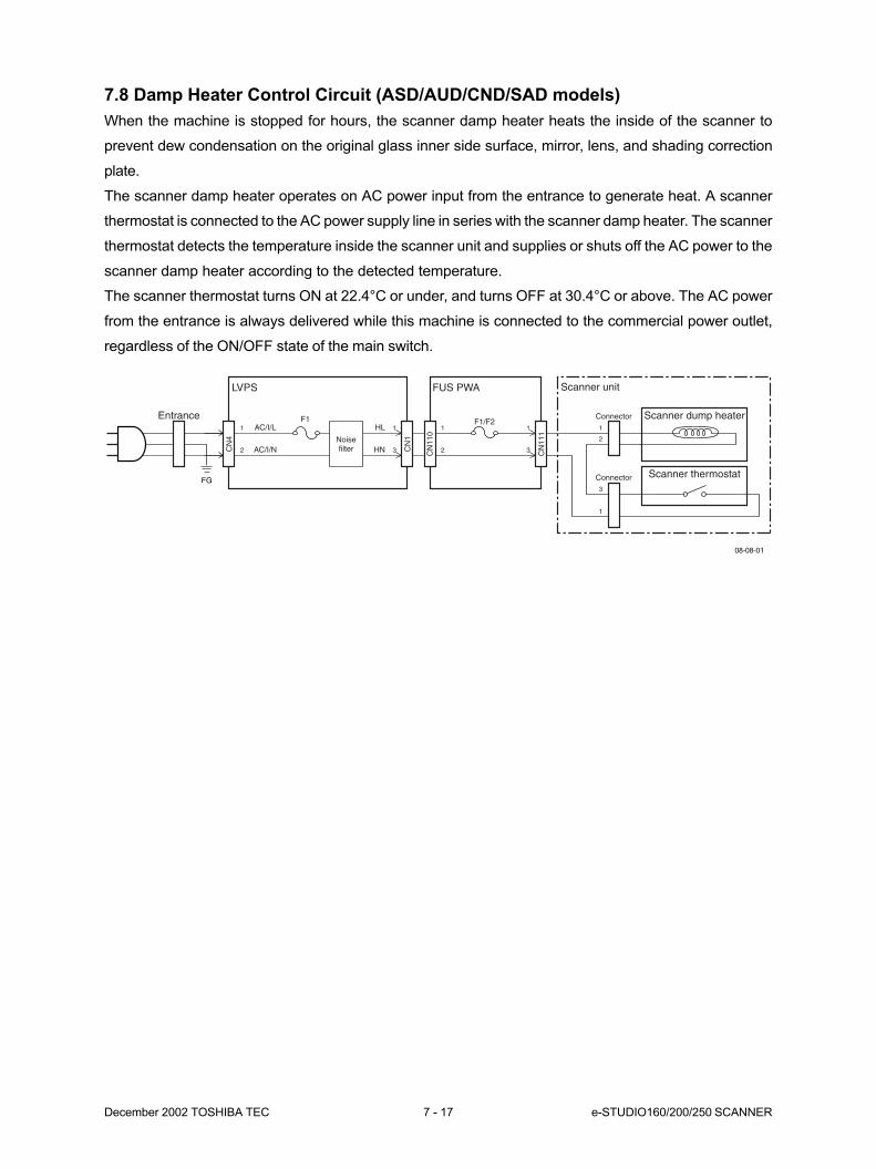
December 2002 TOSHIBA TEC 7 - 17 e-STUDIO160/200/250 SCANNER
7.8 Damp Heater Control Circuit (ASD/AUD/CND/SAD models)
When the machine is stopped for hours, the scanner damp heater heats the inside of the scanner to
prevent dew condensation on the original glass inner side surface, mirror, lens, and shading correction
plate.
The scanner damp heater operates on AC power input from the entrance to generate heat. A scanner
thermostat is connected to the AC power supply line in series with the scanner damp heater. The scanner
thermostat detects the temperature inside the scanner unit and supplies or shuts off the AC power to the
scanner damp heater according to the detected temperature.
The scanner thermostat turns ON at 22.4°C or under, and turns OFF at 30.4°C or above. The AC power
from the entrance is always delivered while this machine is connected to the commercial power outlet,
regardless of the ON/OFF state of the main switch.
08-08-01
FUS PWALVPS
1
2
Scanner thermostat3
1
Scanner unit
HL
HN
FG
Noisefilter
F1EntranceAC/I/L1
AC/I/N2
1
3 CN
111
CN
110
1
3 CN
1
CN
4
Connector
F1/F2Scanner dump heater
1
2
Connector
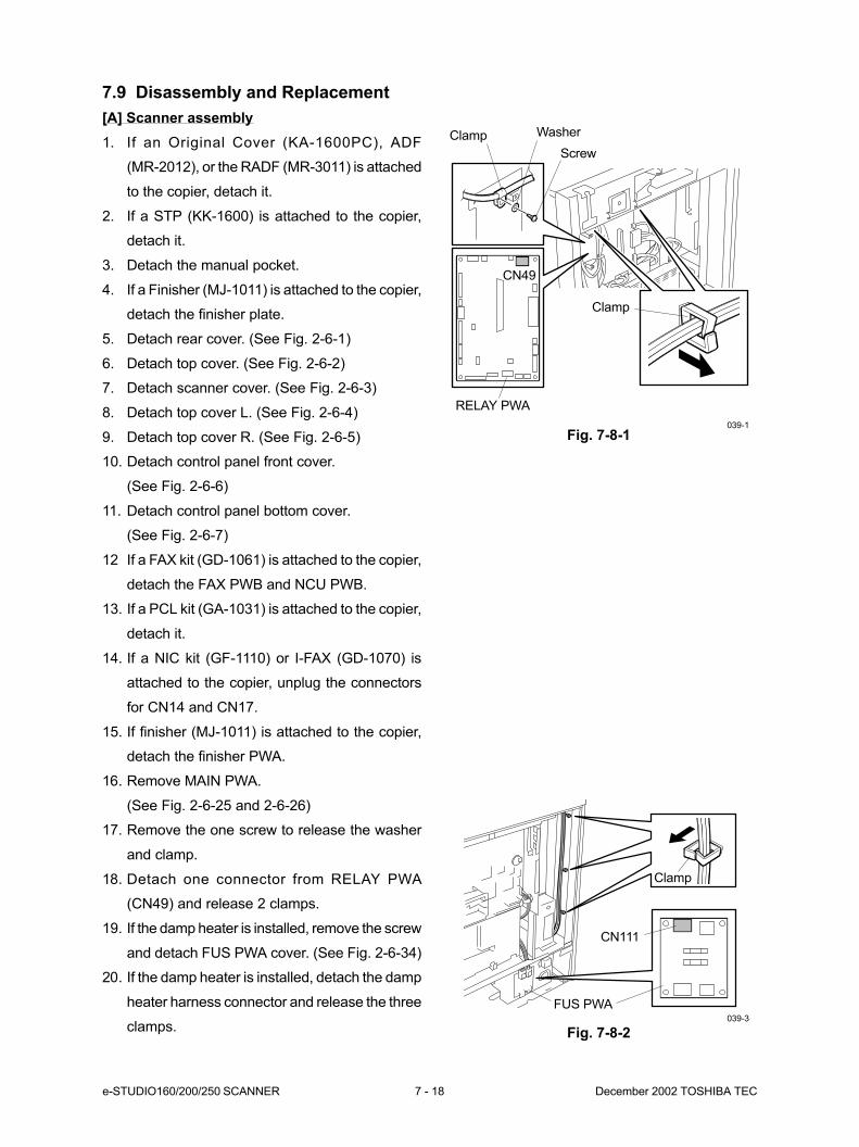
e-STUDIO160/200/250 SCANNER 7 - 18 December 2002 TOSHIBA TEC
Fig. 7-8-1
CN49
RELAY PWA
Clamp
Clamp
CN111
FUS PWA
039-1
039-3
Fig. 7-8-2
Screw
Clamp Washer
7.9 Disassembly and Replacement
[A] Scanner assembly
1. If an Original Cover (KA-1600PC), ADF
(MR-2012), or the RADF (MR-3011) is attached
to the copier, detach it.
2. If a STP (KK-1600) is attached to the copier,
detach it.
3. Detach the manual pocket.
4. If a Finisher (MJ-1011) is attached to the copier,
detach the finisher plate.
5. Detach rear cover. (See Fig. 2-6-1)
6. Detach top cover. (See Fig. 2-6-2)
7. Detach scanner cover. (See Fig. 2-6-3)
8. Detach top cover L. (See Fig. 2-6-4)
9. Detach top cover R. (See Fig. 2-6-5)
10. Detach control panel front cover.
(See Fig. 2-6-6)
11. Detach control panel bottom cover.
(See Fig. 2-6-7)
12 If a FAX kit (GD-1061) is attached to the copier,
detach the FAX PWB and NCU PWB.
13. If a PCL kit (GA-1031) is attached to the copier,
detach it.
14. If a NIC kit (GF-1110) or I-FAX (GD-1070) is
attached to the copier, unplug the connectors
for CN14 and CN17.
15. If finisher (MJ-1011) is attached to the copier,
detach the finisher PWA.
16. Remove MAIN PWA.
(See Fig. 2-6-25 and 2-6-26)
17. Remove the one screw to release the washer
and clamp.
18. Detach one connector from RELAY PWA
(CN49) and release 2 clamps.
19. If the damp heater is installed, remove the screw
and detach FUS PWA cover. (See Fig. 2-6-34)
20. If the damp heater is installed, detach the damp
heater harness connector and release the three
clamps.

December 2002 TOSHIBA TEC 7 - 19 e-STUDIO160/200/250 SCANNER
23. Remove 2 screws.
Fig. 7-8-4
24. Remove 8 screws and remove scanner stay
R.
Fig. 7-8-5
Scanner stay L
Screw
Screw
Screw
Screw
Scanner stay R
Screw
040
041
21. Remove 2 screws to detach the NIC cover.
22. Lift the NIC base plate and release the damp
heater harness.
Fig. 7-8-3039-4
Screw
NIC coverNIC base plate
Damp heater
harness

e-STUDIO160/200/250 SCANNER 7 - 20 December 2002 TOSHIBA TEC
4. Remove the double-sided tape and remove the
ADF glass.
Note: For installing the ADF glass and original
glass and adjusting the tilt, refer to the Ser-
vice Handbook. (See Chapter 1.8)
Fig. 7-8-8
ADF glass
Original glass
043-2
[B] Original glass
1. If an Original Cover (KA-1600PC), ADF
(MR-2012), or the RADF (MR-3011) is attached
to the copier, open it.
2. Remove 2 screws and remove original glass
stay.
3. Remove 4 screws and remove original glass.
Fig. 7-8-7
Screw
Screw
Original glass stay
Original glass
043-1
25. Release the clamp and take out scanner as-
sembly.
Important: 1. After the replacement of the scan-
ner assembly, download firmware
for the scanner PWA. For details,
see chapter 5 of the Service Hand-
book.
2. Download the MAIN PWA firmware,
if necessary, after confirming the
version of it.
3. When the error message “F14” ap-
pears after replacing the scanner
assembly, refer to the Service
Handbook and perform (08-389).
Note: When mounting scanner assembly, be
careful not to damage the actuator.
Scanner assembly
Clamp
Fig. 7-8-6
042

December 2002 TOSHIBA TEC 7 - 21 e-STUDIO160/200/250 SCANNER
[C] Scanner motor
1. If an Original Cover (KA-1600PC), ADF
(MR-2012), or the RADF (MR-3011) is attached
to the copier, detach it.
2. If a STP (KK-1600) is attached to the copier,
detach it.
3. Detach the manual pocket.
4. If a Finisher (MJ-1011) is attached to the copier,
detach the finisher plate.
5. Remove scanner assembly.
(See Fig. 7-8-1 to 7-8-6)
6. Remove original glass. (See Fig. 7-8-7)
7. Detach one connector and detach the motor
harness.
8. Remove one screw and remove the ADF con-
nector plate.
9. Release the clamp and detach the harness.
Fig. 7-8-9 044-1
Motor harness
Clamp
Screw
ADF
connector plate
Harness
Fig. 7-8-12
ScrewScanner motor
Timing
belt 142
046-1
10. Remove 4 screws and remove scanner motor
assembly while releasing timing belt 157.
Fig. 7-8-11
Timing belt 157
Scanner motor
assembly
Screw045-1
e-STUDIO160 series
Fig. 7-8-10 044-2
Motor harness
Clamp
Screw
ADF
connector plate
Harness
e-STUDIO200/250 series
Screw
11. Remove 2 screws and remove Scanner motor
while releasing scanner timing belt 142.
Notes: 1. For adjusting the timing belt when
mounting the scanner motor, refer to the
Service Handbook. (See Chapter 1.8)
2. Do not mix the screws removed.

e-STUDIO160/200/250 SCANNER 7 - 22 December 2002 TOSHIBA TEC
Fig. 7-8-13
CN1
CN2049-6
Screw
INV PWA
assembly
5. Remove 2 screws, release 2 locking supports,
and remove INV PWA.
Fig. 7-8-15
Fig. 7-8-14
Fig. 7-8-16
ScrewScrew
Blind plate
050-6
[D] INV PWA
(e-STUDIO160 series)
1. If an Original Cover (KA-1600PC), ADF
(MR-2012), or the RADF (MR-3011) is attached
to the copier, detach it.
2. Detach top cover. (See Fig. 2-6-2)
3. Detach 2 connector from INV PWA (CN1/CN2).
4. Remove one screw and remove clamp.
5. Release one locking support and remove INV
PWA assembly.
(e-STUDIO200/250 series)
1. If an Original Cover (KA-1600PC), ADF
(MR-2012), or the RADF (MR-3011) is attached
to the copier, detach it.
2. Detach top cover. (See Fig. 2-6-2)
3. Detach 2 connector from INV PWA (CN1/CN2).
4. Remove 2 screws and remove INV PWA as-
sembly.
049-7
INV PWA
Screw
Locking
support
Screw
049-3
Screw
INV PWA
assembly
Connector
Connector
[E] Scanner PWA
1. If an Original Cover (KA-1600PC), ADF
(MR-2012), or the RADF (MR-3011) is attached
to the copier, open it.
2. Remove original glass. (See Fig. 7-8-7)
3. Remove 8 screws and remove blind plate.
(e-STUDIO160 series)
4. Remove 6 screws and remove blind plate.
(e-STUDIO200/250 series)
Clamp
Connector Locking support
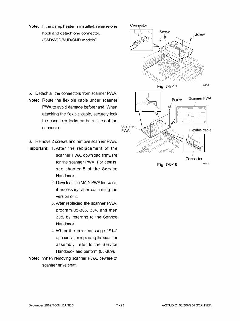
December 2002 TOSHIBA TEC 7 - 23 e-STUDIO160/200/250 SCANNER
Fig. 7-8-18
Scanner
PWA Flexible cable
Connector
051-1
Scanner PWAScrew
5. Detach all the connectors from scanner PWA.
Note: Route the flexible cable under scanner
PWA to avoid damage beforehand. When
attaching the flexible cable, securely lock
the connector locks on both sides of the
connector.
6. Remove 2 screws and remove scanner PWA.
Important: 1. After the replacement of the
scanner PWA, download firmware
for the scanner PWA. For details,
see chapter 5 of the Service
Handbook.
2. Download the MAIN PWA firmware,
if necessary, after confirming the
version of it.
3. After replacing the scanner PWA,
program 05-306, 304, and then
305, by referring to the Service
Handbook.
4. When the error message “F14”
appears after replacing the scanner
assembly, refer to the Service
Handbook and perform (08-389).
Note: When removing scanner PWA, beware of
scanner drive shaft.
Note: If the damp heater is installed, release one
hook and detach one connector.
(SAD/ASD/AUD/CND models)
ScrewScrew
Connector
Fig. 7-8-17 050-7

e-STUDIO160/200/250 SCANNER 7 - 24 December 2002 TOSHIBA TEC
Fig. 7-8-21
ScrewConnector
Ground wire
053-1
Screw INV PWA
Connector
Ground wire
053-2
Fig. 7-8-20
Fig. 7-8-19
Screw
ScrewScrew
Screw
Scanner frame cover
052
e-STUDIO160
9. Remove INV PWA assembly.
(See Fig. 7-8-14) (for e-STUDIO200/250)
10. Detach the connector from INV PWA (CN2),
remove one screw, and detach the ground wire.
e-STUDIO200/250
[F] Exposure lamp
1. If an Original Cover (KA-1600PC), ADF
(MR-2012), or the RADF (MR-3011) is attached
to the copier, detach it.
2. If a STP (KK-1600) is attached to the copier,
detach it.
3. Detach the manual pocket.
4. If a Finisher (MJ-1011) is attached to the copier,
detach the finisher plate.
5. Detach top cover. (See Fig. 2-6-2)
6. Detach scanner cover. (See Fig. 2-6-3)
7. Detach top cover L. (See Fig. 2-6-4)
8. Detach top cover R. (See Fig. 2-6-5)
9. Remove the 12 screws and detach scanner
frame cover.
Note: When attaching scanner frame cover, cor-
rectly fit the tab of scanner frame and
tighten the screws while keeping down
scanner frame cover. Tighten the screws
in the order of numbers. The unnumbered
screws may be tightened not in order.
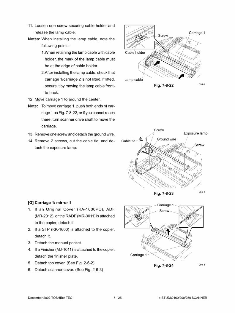
December 2002 TOSHIBA TEC 7 - 25 e-STUDIO160/200/250 SCANNER
Fig. 7-8-22
Screw
Cable holder
Lamp cable
Carriage 1
13. Remove one screw and detach the ground wire.
14. Remove 2 screws, cut the cable tie, and de-
tach the exposure lamp.
Fig. 7-8-23
Screw
Exposure lampScrew
Cable tieGround wire
055-1
054-1
11. Loosen one screw securing cable holder and
release the lamp cable.
Notes: When installing the lamp cable, note the
following points:
1.When retaining the lamp cable with cable
holder, the mark of the lamp cable must
be at the edge of cable holder.
2.After installing the lamp cable, check that
carriage 1/carriage 2 is not lifted. If lifted,
secure it by moving the lamp cable front-
to-back.
12. Move carriage 1 to around the center.
Note: To move carriage 1, push both ends of car-
riage 1 as Fig. 7-8-22, or if you cannot reach
there, turn scanner drive shaft to move the
carriage.
Fig. 7-8-24
Screw
Carriage 1
Carriage 1
056-3
[G] Carriage 1/ mirror 1
1. If an Original Cover (KA-1600PC), ADF
(MR-2012), or the RADF (MR-3011) is attached
to the copier, detach it.
2. If a STP (KK-1600) is attached to the copier,
detach it.
3. Detach the manual pocket.
4. If a Finisher (MJ-1011) is attached to the copier,
detach the finisher plate.
5. Detach top cover. (See Fig. 2-6-2)
6. Detach scanner cover. (See Fig. 2-6-3)
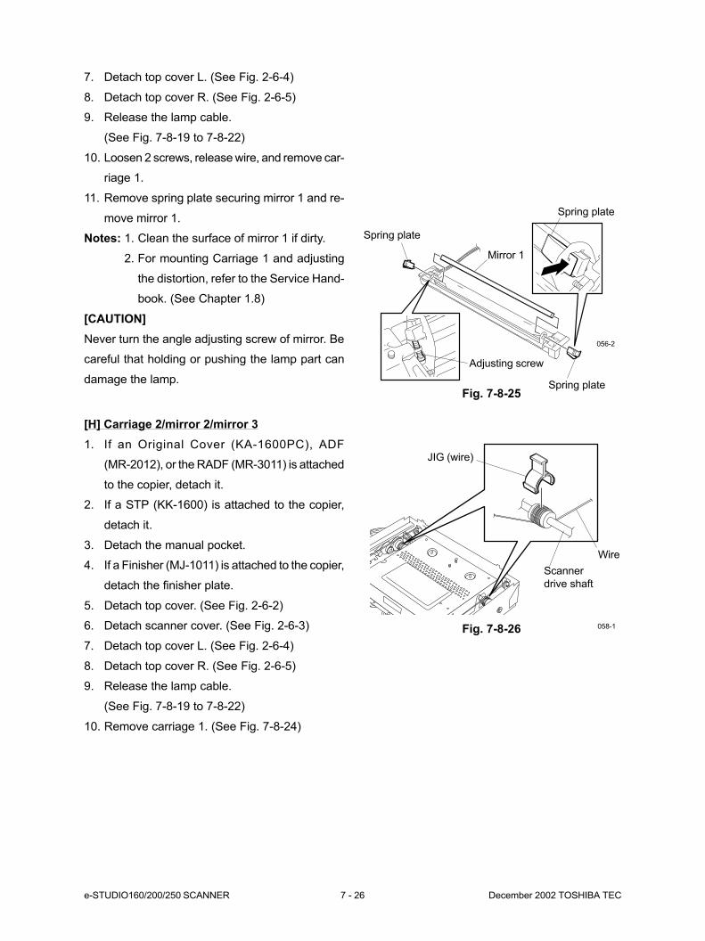
e-STUDIO160/200/250 SCANNER 7 - 26 December 2002 TOSHIBA TEC
Fig. 7-8-26
JIG (wire)
Wire
Scanner
drive shaft
058-1
Fig. 7-8-25
Spring plate
Spring plate
Mirror 1
Spring plate
Adjusting screw
056-2
7. Detach top cover L. (See Fig. 2-6-4)
8. Detach top cover R. (See Fig. 2-6-5)
9. Release the lamp cable.
(See Fig. 7-8-19 to 7-8-22)
10. Loosen 2 screws, release wire, and remove car-
riage 1.
11. Remove spring plate securing mirror 1 and re-
move mirror 1.
Notes: 1. Clean the surface of mirror 1 if dirty.
2. For mounting Carriage 1 and adjusting
the distortion, refer to the Service Hand-
book. (See Chapter 1.8)
[CAUTION]
Never turn the angle adjusting screw of mirror. Be
careful that holding or pushing the lamp part can
damage the lamp.
[H] Carriage 2/mirror 2/mirror 3
1. If an Original Cover (KA-1600PC), ADF
(MR-2012), or the RADF (MR-3011) is attached
to the copier, detach it.
2. If a STP (KK-1600) is attached to the copier,
detach it.
3. Detach the manual pocket.
4. If a Finisher (MJ-1011) is attached to the copier,
detach the finisher plate.
5. Detach top cover. (See Fig. 2-6-2)
6. Detach scanner cover. (See Fig. 2-6-3)
7. Detach top cover L. (See Fig. 2-6-4)
8. Detach top cover R. (See Fig. 2-6-5)
9. Release the lamp cable.
(See Fig. 7-8-19 to 7-8-22)
10. Remove carriage 1. (See Fig. 7-8-24)
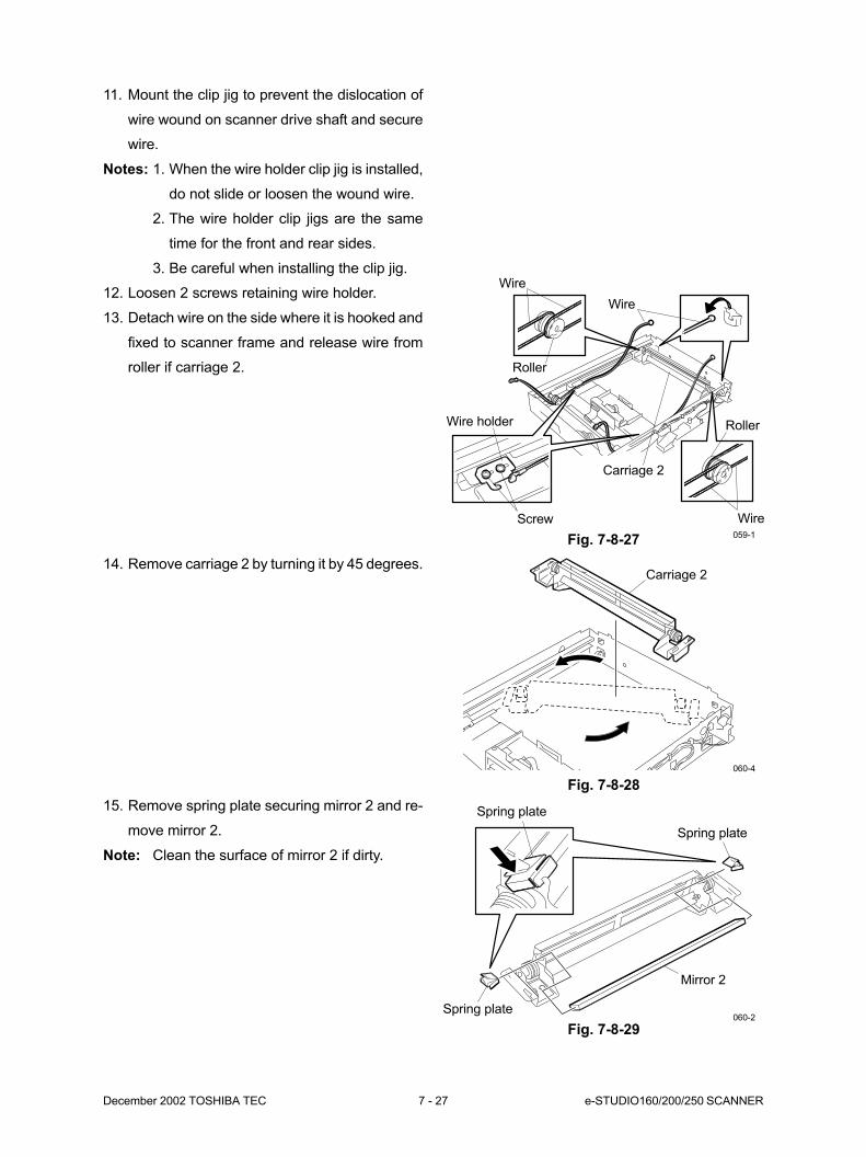
December 2002 TOSHIBA TEC 7 - 27 e-STUDIO160/200/250 SCANNER
Fig. 7-8-27 059-1
Wire
Wire
Roller
Wire holder
Screw
Carriage 2
Roller
Wire
11. Mount the clip jig to prevent the dislocation of
wire wound on scanner drive shaft and secure
wire.
Notes: 1. When the wire holder clip jig is installed,
do not slide or loosen the wound wire.
2. The wire holder clip jigs are the same
time for the front and rear sides.
3. Be careful when installing the clip jig.
12. Loosen 2 screws retaining wire holder.
13. Detach wire on the side where it is hooked and
fixed to scanner frame and release wire from
roller if carriage 2.
14. Remove carriage 2 by turning it by 45 degrees.
Fig. 7-8-28
15. Remove spring plate securing mirror 2 and re-
move mirror 2.
Note: Clean the surface of mirror 2 if dirty.
Fig. 7-8-29
Carriage 2
060-4
Mirror 2
Spring plate
Spring plate
Spring plate060-2
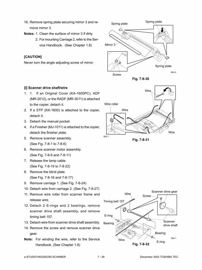
e-STUDIO160/200/250 SCANNER 7 - 28 December 2002 TOSHIBA TEC
Fig. 7-8-31
Fig. 7-8-32
Wire
Wire roller
Wire
Wire
Wire
Timing belt 157
Scanner drive gear
Scanner
drive shaft
Bearing
E-ring
Bearing
E-ring
Wire064-1
Screw
063-1
16. Remove spring plate securing mirror 3 and re-
move mirror 3.
Notes: 1. Clean the surface of mirror 3 if dirty.
2. For mounting Carriage 2, refer to the Ser-
vice Handbook. (See Chapter 1.8)
[CAUTION]
Never turn the angle adjusting screw of mirror.
Fig. 7-8-30
Spring plate
Spring plate
Mirror 3
Screw
Spring plate
060-3
[I] Scanner drive shaft/wire
1. 1. If an Original Cover (KA-1600PC), ADF
(MR-2012), or the RADF (MR-3011) is attached
to the copier, detach it.
2. If a STP (KK-1600) is attached to the copier,
detach it.
3. Detach the manual pocket.
4. If a Finisher (MJ-1011) is attached to the copier,
detach the finisher plate.
5. Remove scanner assembly.
(See Fig. 7-8-1 to 7-8-6)
6. Remove scanner motor assembly.
(See Fig. 7-8-9 and 7-8-11)
7. Release the lamp cable.
(See Fig. 7-8-19 to 7-8-22)
8. Remove the blind plate.
(See Fig. 7-8-16 and 7-8-17)
9. Remove carriage 1. (See Fig. 7-8-24)
10. Detach wire from carriage 2. (See Fig. 7-8-27)
11. Remove wire roller from scanner frame and
release wire.
12. Detach 2 E-rings and 2 bearings, remove
scanner drive shaft assembly, and remove
timing belt 157.
13. Detach wire from scanner drive shaft assembly.
14. Remove the screw and remove scanner drive
gear.
Note: For winding the wire, refer to the Service
Handbook. (See Chapter 1.8)
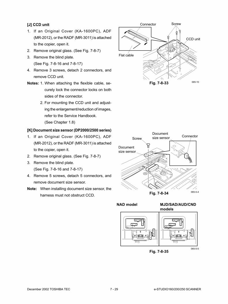
December 2002 TOSHIBA TEC 7 - 29 e-STUDIO160/200/250 SCANNER
Fig. 7-8-33
CCD unit
Flat cable
Connector Screw
065-10
[J] CCD unit
1. If an Original Cover (KA-1600PC), ADF
(MR-2012), or the RADF (MR-3011) is attached
to the copier, open it.
2. Remove original glass. (See Fig. 7-8-7)
3. Remove the blind plate.
(See Fig. 7-8-16 and 7-8-17)
4. Remove 3 screws, detach 2 connectors, and
remove CCD unit.
Notes: 1. When attaching the flexible cable, se-
curely lock the connector locks on both
sides of the connector.
2. For mounting the CCD unit and adjust-
ing the enlargement/reduction of images,
refer to the Service Handbook.
(See Chapter 1.8)
[K] Document size sensor (DP2000/2500 series)
1. If an Original Cover (KA-1600PC), ADF
(MR-2012), or the RADF (MR-3011) is attached
to the copier, open it.
2. Remove original glass. (See Fig. 7-8-7)
3. Remove the blind plate.
(See Fig. 7-8-16 and 7-8-17)
4. Remove 5 screws, detach 5 connectors, and
remove document size sensor.
Note: When installing document size sensor, the
harness must not obstruct CCD.Fig. 7-8-34
Fig. 7-8-35065-5-5
Document
size sensor
065-5-4
Screw
Document
size sensorConnector
NAD model MJD/SAD/AUD/CND
models

e-STUDIO160/200/250 SCANNER 7 - 30 December 2002 TOSHIBA TEC
Fig. 7-8-36
Fig. 7-8-37
Connector
065-11
Scanner thermostat
Screw
065-12
[L] Scanner thermostat
(SAD/ASD/AUD/CND models)
1. If an Original Cover (KA-1600PC), ADF
(MR-2012), or the RADF (MR-3011) is attached
to the copier, open it.
2. Remove original glass. (See Fig. 7-8-7)
3. Remove the blind plate.
(See Fig. 7-8-16 and 7-8-17)
4. Detach 2 connectors.
5. Remove 2 screws and remove the scanner
thermostat.
Screw
Hook
Damp heater plate
065-9
[M] Damp heater
(SAD/ASD/AUD/CND models)
1. If an Original Cover (KA-1600PC), ADF
(MR-2012), or the RADF (MR-3011) is attached
to the copier, open it.
2. Remove original glass. (See Fig. 7-8-7)
3. Move carriage 1 to around the center.
(See Fig. 7-8-22)
4. Peel off the sheet. (e-STUDIO160 series)
5. Remove the screw, release the hook, and de-
tach the damp heater plate.
(e-STUDIO200/250 series)
Fig. 7-8-38
Sheet
065-13
e-STUDIO160 series
e-STUDIO200/250 series
Fig. 7-8-39
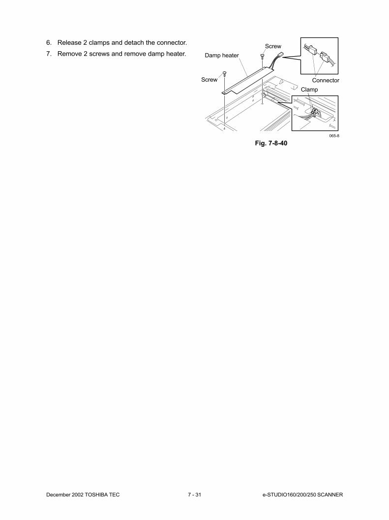
December 2002 TOSHIBA TEC 7 - 31 e-STUDIO160/200/250 SCANNER
Screw
Screw
Damp heater
Connector
Clamp
065-8
Fig. 7-8-40
6. Release 2 clamps and detach the connector.
7. Remove 2 screws and remove damp heater.
8. PRINTING ................................................. 8-1
8.1 General Description .................................................................................. 8-1
8.2 Structure ................................................................................................... 8-2
8.3 Laser Diode .............................................................................................. 8-5
8.4 Disassembly and Replacement ................................................................ 8-6
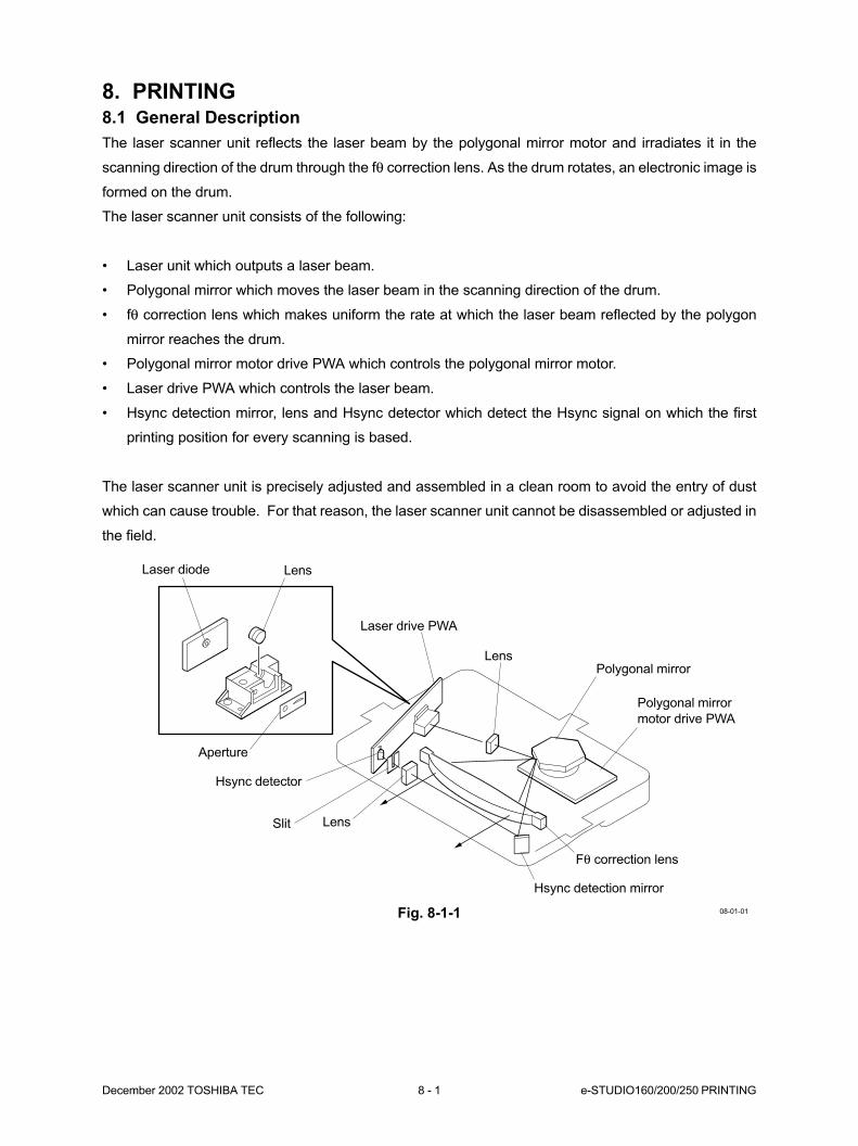
December 2002 TOSHIBA TEC 8 - 1 e-STUDIO160/200/250 PRINTING
8. PRINTING8.1 General Description
The laser scanner unit reflects the laser beam by the polygonal mirror motor and irradiates it in the
scanning direction of the drum through the fθ correction lens. As the drum rotates, an electronic image is
formed on the drum.
The laser scanner unit consists of the following:
• Laser unit which outputs a laser beam.
• Polygonal mirror which moves the laser beam in the scanning direction of the drum.
• fθ correction lens which makes uniform the rate at which the laser beam reflected by the polygon
mirror reaches the drum.
• Polygonal mirror motor drive PWA which controls the polygonal mirror motor.
• Laser drive PWA which controls the laser beam.
• Hsync detection mirror, lens and Hsync detector which detect the Hsync signal on which the first
printing position for every scanning is based.
The laser scanner unit is precisely adjusted and assembled in a clean room to avoid the entry of dust
which can cause trouble. For that reason, the laser scanner unit cannot be disassembled or adjusted in
the field.
Fig. 8-1-1 08-01-01
Lens
Aperture
Laser drive PWA
Lens
Polygonal mirror
motor drive PWA
Fθ correction lens
Hsync detection mirror
Lens
Hsync detector
Laser diode
Polygonal mirror
Slit
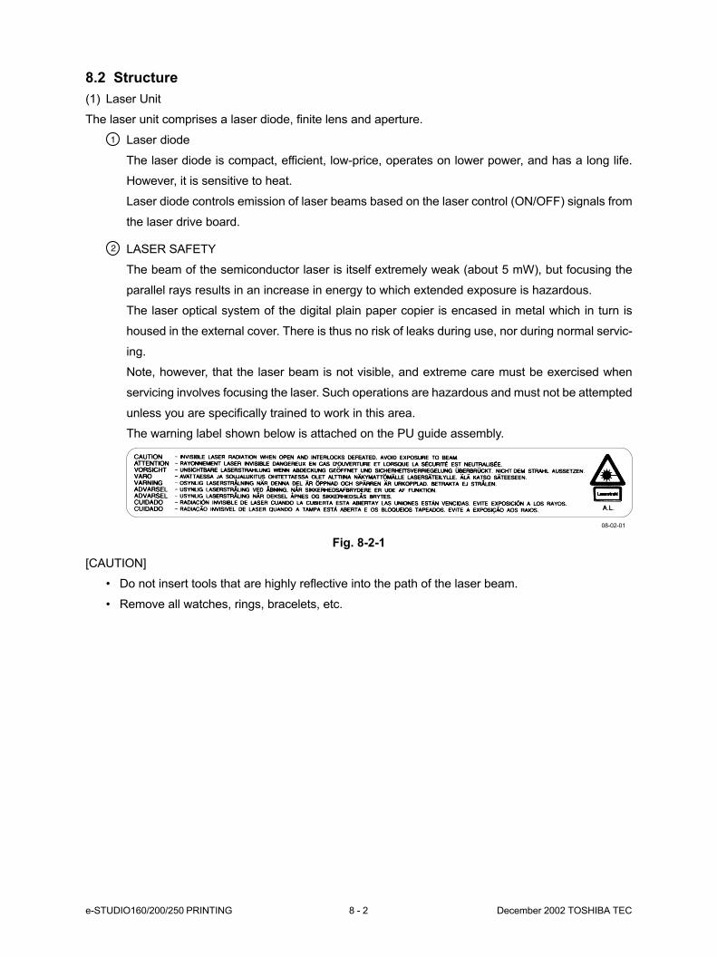
e-STUDIO160/200/250 PRINTING 8 - 2 December 2002 TOSHIBA TEC
8.2 Structure
(1) Laser Unit
The laser unit comprises a laser diode, finite lens and aperture.
Laser diode
The laser diode is compact, efficient, low-price, operates on lower power, and has a long life.
However, it is sensitive to heat.
Laser diode controls emission of laser beams based on the laser control (ON/OFF) signals from
the laser drive board.
LASER SAFETY
The beam of the semiconductor laser is itself extremely weak (about 5 mW), but focusing the
parallel rays results in an increase in energy to which extended exposure is hazardous.
The laser optical system of the digital plain paper copier is encased in metal which in turn is
housed in the external cover. There is thus no risk of leaks during use, nor during normal servic-
ing.
Note, however, that the laser beam is not visible, and extreme care must be exercised when
servicing involves focusing the laser. Such operations are hazardous and must not be attempted
unless you are specifically trained to work in this area.
The warning label shown below is attached on the PU guide assembly.
Fig. 8-2-1
[CAUTION]
• Do not insert tools that are highly reflective into the path of the laser beam.
• Remove all watches, rings, bracelets, etc.
08-02-01

December 2002 TOSHIBA TEC 8 - 3 e-STUDIO160/200/250 PRINTING
(2) Polygonal-Mirror Motor Unit
The polygonal-mirror motor unit comprises a po-
lygonal mirror and a polygonal-mirror motor.
Polygonal-mirror motor
The polygonal-mirror motor rotates the po-
lygonal mirror at high speed.
The DC motor controls the rotation speed
of the mirror as follows:
e-STUDIO160 series
600 dpi : 20,527.56 rpm
400 dpi : 13,382.60 rpm
e-STUDIO200/250 series
600 dpi : 27,874.016 rpm
400 dpi : 18,582.677 rpm
Polygonal mirror
The laser beams emitted from the laser di-
ode are reflected by this mirror. As the po-
lygonal mirror is rotated by the polygonal-
mirror motor, the direction of the reflected
laser light moves in sync with the rotation.
The direction of movement is the primary
scanning direction of the image with each
single scan ending in one plane of the po-
lygonal mirror.
As the polygonal mirror has six planes, six
scans are completed in one rotation of the
polygonal mirror.
Fig. 8-2-2
One scan is completed by completion of steps A to C .
One scan is carried out on one plane of the polygonal
mirror. Six scans can be carried out with one rotation of
the polygonal mirror.
Laser light
Drum
Drum
Drum
Laser light
Laser light
B
C
A
09-02-05
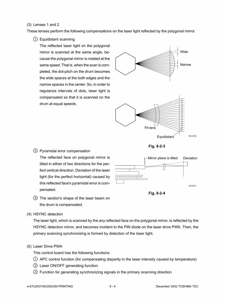
e-STUDIO160/200/250 PRINTING 8 - 4 December 2002 TOSHIBA TEC
(3) Lenses 1 and 2
These lenses perform the following compensations on the laser light reflected by the polygonal mirror.
Equidistant scanning
The reflected laser light on the polygonal
mirror is scanned at the same angle, be-
cause the polygonal mirror is rotated at the
same speed. That is, when the scan is com-
pleted, the dot-pitch on the drum becomes
the wide spaces at the both edges and the
narrow spaces in the center. So, in order to
regularize intervals of dots, laser light is
compensated so that it is scanned on the
drum at equal speeds.
Fig. 8-2-3
Pyramidal error compensation
The reflected face on polygonal mirror is
tilted in either of two directions for the per-
fect vertical direction. Deviation of the laser
light (for the perfect horizontal) caused by
this reflected face's pyramidal error is com-
pensated.
The section's shape of the laser beam on
the drum is compensated.
Fig. 8-2-4
Equidistant
Wide
Narrow
Fθ lens
09-02-06
09-02-07
Mirror plane is tilted Deviation
(4) HSYNC detection
The laser light, which is scanned by the any reflected face on the polygonal mirror, is reflected by the
HSYNC detection mirror, and becomes incident to the PIN diode on the laser drive PWA. Then, the
primary scanning synchronizing is formed by detection of the laser light.
(5) Laser Drive PWA
This control board has the following functions:
APC control function (for compensating disparity in the laser intensity caused by temperature)
Laser ON/OFF generating function
Function for generating synchronizing signals in the primary scanning direction
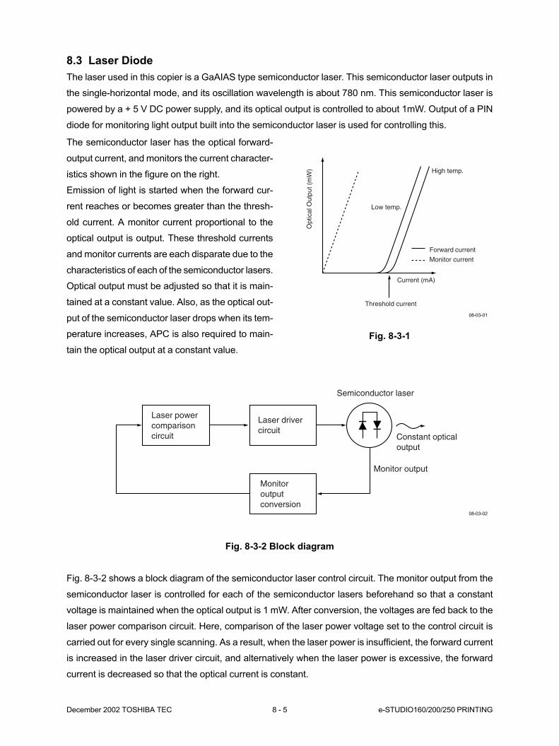
December 2002 TOSHIBA TEC 8 - 5 e-STUDIO160/200/250 PRINTING
8.3 Laser Diode
The laser used in this copier is a GaAIAS type semiconductor laser. This semiconductor laser outputs in
the single-horizontal mode, and its oscillation wavelength is about 780 nm. This semiconductor laser is
powered by a + 5 V DC power supply, and its optical output is controlled to about 1mW. Output of a PIN
diode for monitoring light output built into the semiconductor laser is used for controlling this.
The semiconductor laser has the optical forward-
output current, and monitors the current character-
istics shown in the figure on the right.
Emission of light is started when the forward cur-
rent reaches or becomes greater than the thresh-
old current. A monitor current proportional to the
optical output is output. These threshold currents
and monitor currents are each disparate due to the
characteristics of each of the semiconductor lasers.
Optical output must be adjusted so that it is main-
tained at a constant value. Also, as the optical out-
put of the semiconductor laser drops when its tem-
perature increases, APC is also required to main-
tain the optical output at a constant value.
Fig. 8-3-1
Fig. 8-3-2 Block diagram
Fig. 8-3-2 shows a block diagram of the semiconductor laser control circuit. The monitor output from the
semiconductor laser is controlled for each of the semiconductor lasers beforehand so that a constant
voltage is maintained when the optical output is 1 mW. After conversion, the voltages are fed back to the
laser power comparison circuit. Here, comparison of the laser power voltage set to the control circuit is
carried out for every single scanning. As a result, when the laser power is insufficient, the forward current
is increased in the laser driver circuit, and alternatively when the laser power is excessive, the forward
current is decreased so that the optical current is constant.
Threshold currentO
ptic
al O
utpu
t (m
W)
Low temp.
High temp.
Forward current
Monitor current
Current (mA)
Monitor output
Monitoroutputconversion
Laser powercomparisoncircuit
Laser drivercircuit
Semiconductor laser
Constant opticaloutput
08-03-01
08-03-02
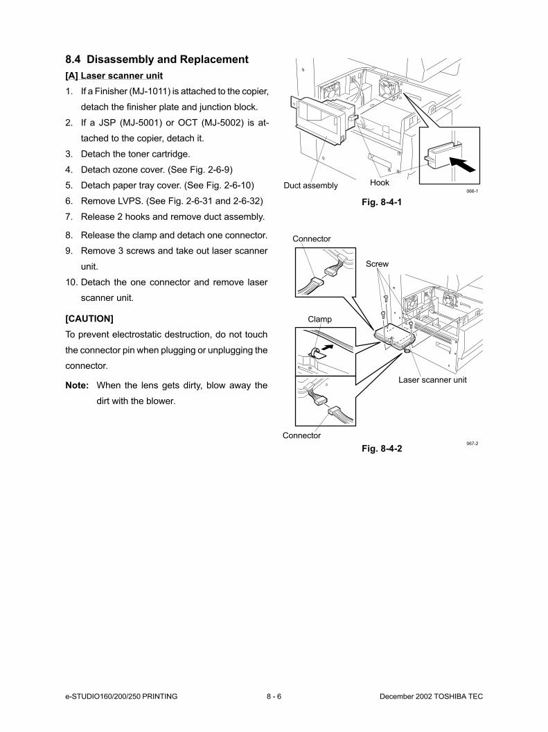
e-STUDIO160/200/250 PRINTING 8 - 6 December 2002 TOSHIBA TEC
8.4 Disassembly and Replacement
[A] Laser scanner unit
1. If a Finisher (MJ-1011) is attached to the copier,
detach the finisher plate and junction block.
2. If a JSP (MJ-5001) or OCT (MJ-5002) is at-
tached to the copier, detach it.
3. Detach the toner cartridge.
4. Detach ozone cover. (See Fig. 2-6-9)
5. Detach paper tray cover. (See Fig. 2-6-10)
6. Remove LVPS. (See Fig. 2-6-31 and 2-6-32)
7. Release 2 hooks and remove duct assembly.
Duct assembly Hook
Screw
Connector
Clamp
066-1
Laser scanner unit
Fig. 8-4-1
8. Release the clamp and detach one connector.
9. Remove 3 screws and take out laser scanner
unit.
10. Detach the one connector and remove laser
scanner unit.
[CAUTION]
To prevent electrostatic destruction, do not touch
the connector pin when plugging or unplugging the
connector.
Note: When the lens gets dirty, blow away the
dirt with the blower.
Fig. 8-4-2067-2
Connector

9. PAPER FEEDING SYSTEM ..................... 9-1
9.1 General Description .................................................................................. 9-1
9.2 Construction .............................................................................................. 9-1
9.3 Drive Description....................................................................................... 9-3
9.3.1 Pickup feed roller, feed roller and registration roller ..................... 9-3
9.3.2 Tray lift shaft ................................................................................. 9-3
9.4 Description of Operation ........................................................................... 9-4
9.4.1 Tray section .................................................................................. 9-4
9.4.2 Paper feeding section .................................................................. 9-4
9.4.3 Paper separation .......................................................................... 9-5
9.4.4 Cassette feeding operation .......................................................... 9-6
9.5 Function of Each Part ............................................................................... 9-7
9.6 Tray-up Motor Drive Circuit ....................................................................... 9-9
9.7 Disassembly and Replacement ................................................................ 9-10

December 2002 TOSHIBA TEC 9 - 1 e-STUDIO160/200/250 PAPER FEEDING SYSTEM
9. PAPER FEEDING SYSTEM9.1 General Description
The paper feeding section feeds the paper from the paper cassette to the transfer section.
Driving of each of the paper feed and transport rollers is controlled by turning ON and OFF the clutches.
Each sensor detects the transport state of the paper.
9.2 Construction
The paper feeding system section consists of the following parts:
• Paper tray
• Tray-up assembly
• Pickup feed roller
• Pickup roller
• Paper empty sensor
• Pickup sensor
• Separation roller
• Feed sensor
• Registration roller
• Pinch roller
09-02-01
Pinch roller
Paper tray Paper empty sensor
Tray-up assembly
Pickup sensor
Separation
roller
Pickup feed
roller
Feed sensor
Registration
roller
Pickup roller
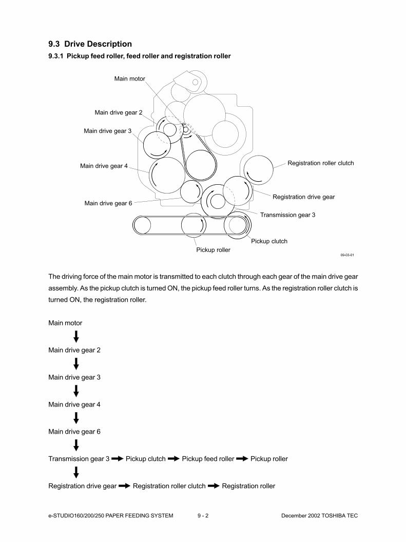
e-STUDIO160/200/250 PAPER FEEDING SYSTEM 9 - 2 December 2002 TOSHIBA TEC
9.3 Drive Description
9.3.1 Pickup feed roller, feed roller and registration roller
The driving force of the main motor is transmitted to each clutch through each gear of the main drive gear
assembly. As the pickup clutch is turned ON, the pickup feed roller turns. As the registration roller clutch is
turned ON, the registration roller.
Main motor
Main drive gear 2
Main drive gear 3
Main drive gear 4
Main drive gear 6
Transmission gear 3 Pickup clutch Pickup feed roller Pickup roller
Registration drive gear Registration roller clutch Registration roller
09-03-01
Main drive gear 6
Registration roller clutch
Registration drive gear
Transmission gear 3
Pickup clutch
Pickup roller
Main motor
Main drive gear 2
Main drive gear 3
Main drive gear 4
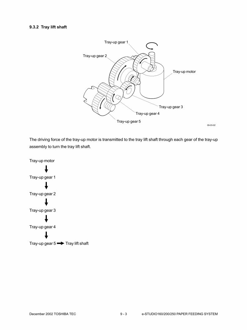
December 2002 TOSHIBA TEC 9 - 3 e-STUDIO160/200/250 PAPER FEEDING SYSTEM
9.3.2 Tray lift shaft
The driving force of the tray-up motor is transmitted to the tray lift shaft through each gear of the tray-up
assembly to turn the tray lift shaft.
Tray-up motor
Tray-up gear 1
Tray-up gear 2
Tray-up gear 3
Tray-up gear 4
Tray-up gear 5 Tray lift shaft
09-03-02
Tray-up gear 1
Tray-up motor
Tray-up gear 3
Tray-up gear 4
Tray-up gear 5
Tray-up gear 2
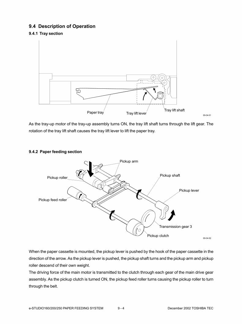
e-STUDIO160/200/250 PAPER FEEDING SYSTEM 9 - 4 December 2002 TOSHIBA TEC
9.4 Description of Operation
9.4.1 Tray section
As the tray-up motor of the tray-up assembly turns ON, the tray lift shaft turns through the lift gear. The
rotation of the tray lift shaft causes the tray lift lever to lift the paper tray.
9.4.2 Paper feeding section
09-04-01
When the paper cassette is mounted, the pickup lever is pushed by the hook of the paper cassette in the
direction of the arrow. As the pickup lever is pushed, the pickup shaft turns and the pickup arm and pickup
roller descend of their own weight.
The driving force of the main motor is transmitted to the clutch through each gear of the main drive gear
assembly. As the pickup clutch is turned ON, the pickup feed roller turns causing the pickup roller to turn
through the belt.
09-04-02
Tray lift leverTray lift shaft
Paper tray
Pickup clutch
Transmission gear 3
Pickup lever
Pickup shaft
Pickup arm
Pickup feed roller
Pickup roller
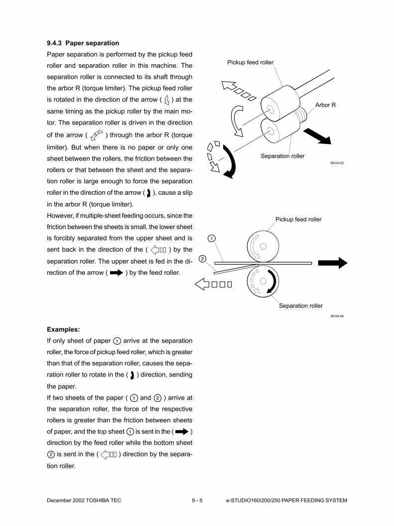
December 2002 TOSHIBA TEC 9 - 5 e-STUDIO160/200/250 PAPER FEEDING SYSTEM
9.4.3 Paper separation
Paper separation is performed by the pickup feed
roller and separation roller in this machine. The
separation roller is connected to its shaft through
the arbor R (torque limiter). The pickup feed roller
is rotated in the direction of the arrow ( ) at the
same timing as the pickup roller by the main mo-
tor. The separation roller is driven in the direction
of the arrow ( ) through the arbor R (torque
limiter). But when there is no paper or only one
sheet between the rollers, the friction between the
rollers or that between the sheet and the separa-
tion roller is large enough to force the separation
roller in the direction of the arrow ( ), cause a slip
in the arbor R (torque limiter).
However, if multiple-sheet feeding occurs, since the
friction between the sheets is small, the lower sheet
is forcibly separated from the upper sheet and is
sent back in the direction of the ( ) by the
separation roller. The upper sheet is fed in the di-
rection of the arrow ( ) by the feed roller.
09-04-04
09-04-03
Examples:
If only sheet of paper arrive at the separation
roller, the force of pickup feed roller, which is greater
than that of the separation roller, causes the sepa-
ration roller to rotate in the ( ) direction, sending
the paper.
If two sheets of the paper ( and ) arrive at
the separation roller, the force of the respective
rollers is greater than the friction between sheets
of paper, and the top sheet is sent in the ( )
direction by the feed roller while the bottom sheet
is sent in the ( ) direction by the separa-
tion roller.
Pickup feed roller
Separation roller
Arbor R
Pickup feed roller
Separation roller

e-STUDIO160/200/250 PAPER FEEDING SYSTEM 9 - 6 December 2002 TOSHIBA TEC
9.4.4 Cassette feeding operation
[A] From power-on to the ready state
(1) When the power is turned ON, the tray-up motor of the tray-up assembly turns ON to lift the paper tray
of the paper cassette.
(2) When the paper tray pushes up the pickup roller to turn ON (L → H) the pickup sensor, the tray-up
motor turns OFF. At this time, the presence or absence of paper is detected by the paper empty
sensor.
(3) Even if the power is turned ON while the paper cassette is not mounted, the tray-up motor will not turn
ON.
[B] Ready state
(1) When the paper tray of the paper cassette ascends and the presence or absence of paper is de-
tected, the standby mode will be activated.
(2) When the paper cassette is removed while in the standby mode, the tray lift shaft is dislocated from
the tray-up assembly, thereby causing the tray to descend. When the paper cassette is mounted
again, the tray ascends causing the presence or absence of paper to be detected.
[C] Paper feeding
(1) When the pickup clutch is turned ON, the power of the main motor is transmitted to the pickup feed
roller through each gear for rotation.
(2) The rotation of the pickup feed roller is transmitted to the pickup roller through the belt.
(3) The paper is transported from the paper cassette by means of the pickup roller and pickup feed roller.
(4) A fixed time after the feed sensor detects the top of paper, the registration roller clutch is turned ON.
(5) When the registration roller clutch is turned ON, the power of the main motor is transmitted to the
registration roller through each gear for rotation.
(6) The paper is transported by means of the registration roller and pinch roller. Even if the paper has
been transported askew, the paper is pressed to the registration roller during the time from the mo-
ment when the feed sensor turns ON to the moment when the registration roller clutch is turned ON
to make the paper sag, thereby correcting it to be horizontal.
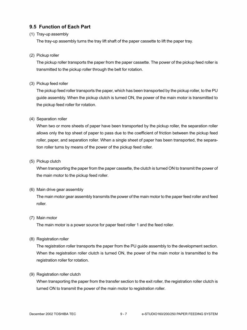
December 2002 TOSHIBA TEC 9 - 7 e-STUDIO160/200/250 PAPER FEEDING SYSTEM
9.5 Function of Each Part
(1) Tray-up assembly
The tray-up assembly turns the tray lift shaft of the paper cassette to lift the paper tray.
(2) Pickup roller
The pickup roller transports the paper from the paper cassette. The power of the pickup feed roller is
transmitted to the pickup roller through the belt for rotation.
(3) Pickup feed roller
The pickup feed roller transports the paper, which has been transported by the pickup roller, to the PU
guide assembly. When the pickup clutch is turned ON, the power of the main motor is transmitted to
the pickup feed roller for rotation.
(4) Separation roller
When two or more sheets of paper have been transported by the pickup roller, the separation roller
allows only the top sheet of paper to pass due to the coefficient of friction between the pickup feed
roller, paper, and separation roller. When a single sheet of paper has been transported, the separa-
tion roller turns by means of the power of the pickup feed roller.
(5) Pickup clutch
When transporting the paper from the paper cassette, the clutch is turned ON to transmit the power of
the main motor to the pickup feed roller.
(6) Main drive gear assembly
The main motor gear assembly transmits the power of the main motor to the paper feed roller and feed
roller.
(7) Main motor
The main motor is a power source for paper feed roller 1 and the feed roller.
(8) Registration roller
The registration roller transports the paper from the PU guide assembly to the development section.
When the registration roller clutch is turned ON, the power of the main motor is transmitted to the
registration roller for rotation.
(9) Registration roller clutch
When transporting the paper from the transfer section to the exit roller, the registration roller clutch is
turned ON to transmit the power of the main motor to registration roller.
e-STUDIO160/200/250 PAPER FEEDING SYSTEM 9 - 8 December 2002 TOSHIBA TEC
(10) Pinch roller
The pinch roller helps registration roller transport the paper. Pressed to registration roller by the
spring, the pinch roller turns with the power of registration roller.
(11) Paper empty sensor
The paper empty sensor detects the presence or absence of paper in the paper cassette.
(12) Pickup sensor
The pickup sensor detects that the tray of the paper cassette has been lifted to the specified posi-
tion. The tray is lifted until the pickup roller is pushed by the tray to turn OFF the pickup sensor.
(13) Feed sensor
The feed sensor detects the transport of the paper by the PU guide assembly. Registration clutch
turns ON a fixed time after the feed sensor detects the top of paper.

December 2002 TOSHIBA TEC 9 - 9 e-STUDIO160/200/250 PAPER FEEDING SYSTEM
9.6 Tray-up Motor Drive Circuit
Tray-up motor : Driven by IC4 (PWA-F-RLY : TA8428K)
The block diagram of TA8428K is shown below.
IN1 and IN2 are input terminals for the signals from the I/O port GA-1. In the control section, the motor is
controlled (ON and OFF) based on the signals from the I/O port GA-1. For the control, refer to the table
below.
1 2 3 4 5 6 7
IN1 IN2 M(+) GND M(–) N.C. VCC
Control logic
Overheatprotection
circuit
Overcurrentprotection
circuit
IN1 IN2 M (+) M (-)
H H L L BRAKE
L H L H CCW (upward)
H L H L CW (downward)
L L OFF (high impedance) STOP
Input OutputDescription
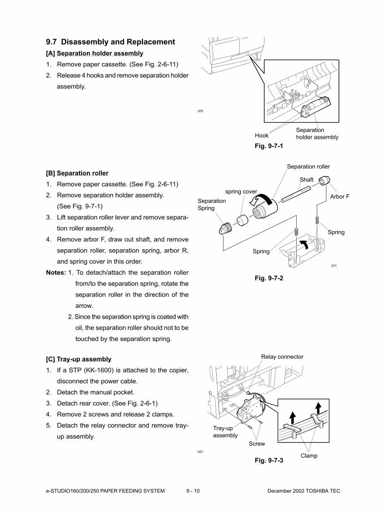
e-STUDIO160/200/250 PAPER FEEDING SYSTEM 9 - 10 December 2002 TOSHIBA TEC
[C] Tray-up assembly
1. If a STP (KK-1600) is attached to the copier,
disconnect the power cable.
2. Detach the manual pocket.
3. Detach rear cover. (See Fig. 2-6-1)
4. Remove 2 screws and release 2 clamps.
5. Detach the relay connector and remove tray-
up assembly.
Fig. 9-7-3
Separation roller
Shaft
Arbor Fspring cover
Spring
Spring
Separation
Spring
071
Relay connector
Clamp
Screw
Tray-up
assembly
037
9.7 Disassembly and Replacement
[A] Separation holder assembly
1. Remove paper cassette. (See Fig. 2-6-11)
2. Release 4 hooks and remove separation holder
assembly.
[B] Separation roller
1. Remove paper cassette. (See Fig. 2-6-11)
2. Remove separation holder assembly.
(See Fig. 9-7-1)
3. Lift separation roller lever and remove separa-
tion roller assembly.
4. Remove arbor F, draw out shaft, and remove
separation roller, separation spring, arbor R,
and spring cover in this order.
Notes: 1. To detach/attach the separation roller
from/to the separation spring, rotate the
separation roller in the direction of the
arrow.
2. Since the separation spring is coated with
oil, the separation roller should not to be
touched by the separation spring.
Fig. 9-7-2
HookSeparation
holder assembly
070
Fig. 9-7-1
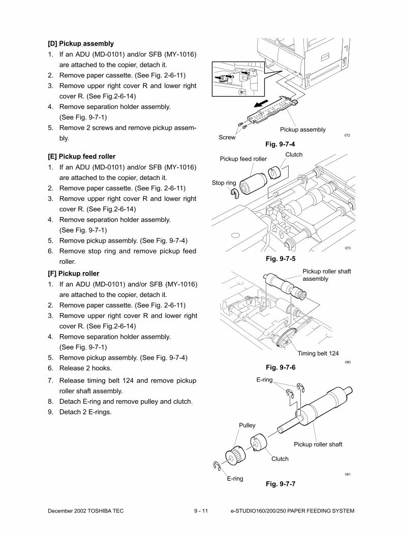
December 2002 TOSHIBA TEC 9 - 11 e-STUDIO160/200/250 PAPER FEEDING SYSTEM
[E] Pickup feed roller
1. If an ADU (MD-0101) and/or SFB (MY-1016)
are attached to the copier, detach it.
2. Remove paper cassette. (See Fig. 2-6-11)
3. Remove upper right cover R and lower right
cover R. (See Fig.2-6-14)
4. Remove separation holder assembly.
(See Fig. 9-7-1)
5. Remove pickup assembly. (See Fig. 9-7-4)
6. Remove stop ring and remove pickup feed
roller.
Clutch
Stop ring
Pickup feed roller
073
Fig. 9-7-4Screw
Pickup assembly072
Fig. 9-7-5
[F] Pickup roller
1. If an ADU (MD-0101) and/or SFB (MY-1016)
are attached to the copier, detach it.
2. Remove paper cassette. (See Fig. 2-6-11)
3. Remove upper right cover R and lower right
cover R. (See Fig.2-6-14)
4. Remove separation holder assembly.
(See Fig. 9-7-1)
5. Remove pickup assembly. (See Fig. 9-7-4)
6. Release 2 hooks. Fig. 9-7-6
Pickup roller shaft
assembly
Timing belt 124
080
Pulley
Pickup roller shaft
Clutch
E-ring081
7. Release timing belt 124 and remove pickup
roller shaft assembly.
8. Detach E-ring and remove pulley and clutch.
9. Detach 2 E-rings.
E-ring
[D] Pickup assembly
1. If an ADU (MD-0101) and/or SFB (MY-1016)
are attached to the copier, detach it.
2. Remove paper cassette. (See Fig. 2-6-11)
3. Remove upper right cover R and lower right
cover R. (See Fig.2-6-14)
4. Remove separation holder assembly.
(See Fig. 9-7-1)
5. Remove 2 screws and remove pickup assem-
bly.
Fig. 9-7-7

10. DRIVE SYSTEM ....................................... 10-1
10.1 Construction of Drive System ................................................................... 10-1
10.2 Description of Operations ......................................................................... 10-2
10.2.1 Part A ........................................................................................... 10-2
10.2.2 Part B ........................................................................................... 10-3
10.2.3 Part C ........................................................................................... 10-4
10.3 Disassembly and Replacement ................................................................ 10-6
10.4 Main Motor ................................................................................................ 10-11
10.4.1 Main motor drive .......................................................................... 10-11
10.4.2 Control signals ............................................................................. 10-12
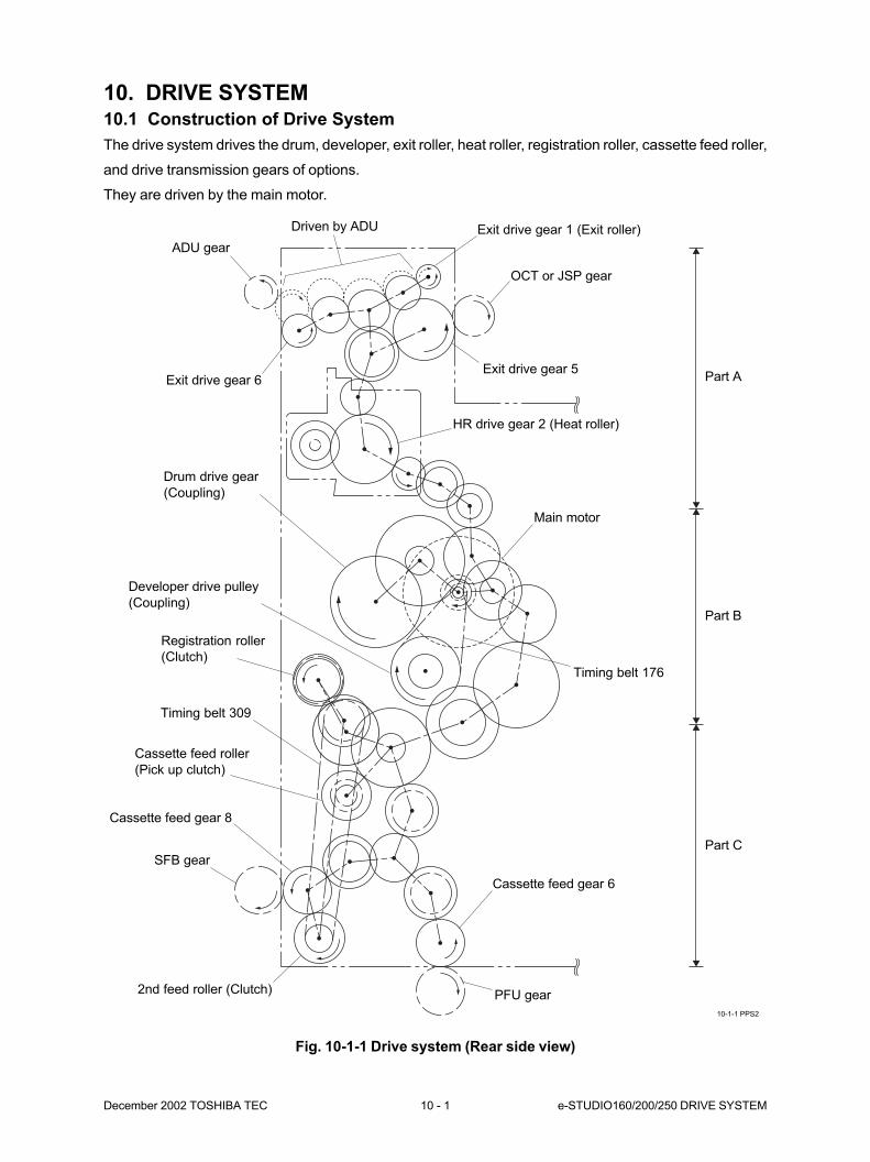
December 2002 TOSHIBA TEC 10 - 1 e-STUDIO160/200/250 DRIVE SYSTEM
10. DRIVE SYSTEM10.1 Construction of Drive System
The drive system drives the drum, developer, exit roller, heat roller, registration roller, cassette feed roller,
and drive transmission gears of options.
They are driven by the main motor.
Fig. 10-1-1 Drive system (Rear side view)
10-1-1 PPS2
Exit drive gear 1 (Exit roller)Driven by ADU
ADU gear
Exit drive gear 6
Drum drive gear
(Coupling)
Developer drive pulley
(Coupling)
Registration roller
(Clutch)
Timing belt 309
Cassette feed roller
(Pick up clutch)
Cassette feed gear 8
SFB gear
2nd feed roller (Clutch) PFU gear
Cassette feed gear 6
Timing belt 176
Main motor
HR drive gear 2 (Heat roller)
Exit drive gear 5
OCT or JSP gear
Part A
Part B
Part C
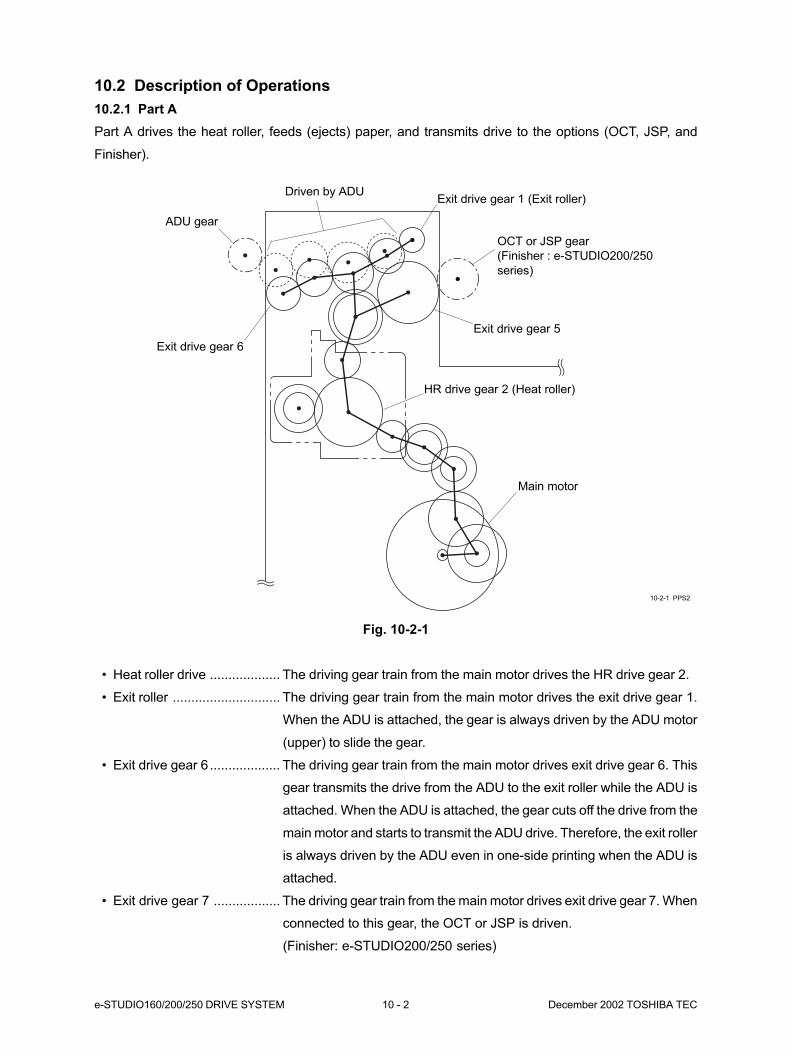
e-STUDIO160/200/250 DRIVE SYSTEM 10 - 2 December 2002 TOSHIBA TEC
10.2 Description of Operations
10.2.1 Part A
Part A drives the heat roller, feeds (ejects) paper, and transmits drive to the options (OCT, JSP, and
Finisher).
Fig. 10-2-1
• Heat roller drive ................... The driving gear train from the main motor drives the HR drive gear 2.
• Exit roller ............................. The driving gear train from the main motor drives the exit drive gear 1.
When the ADU is attached, the gear is always driven by the ADU motor
(upper) to slide the gear.
• Exit drive gear 6................... The driving gear train from the main motor drives exit drive gear 6. This
gear transmits the drive from the ADU to the exit roller while the ADU is
attached. When the ADU is attached, the gear cuts off the drive from the
main motor and starts to transmit the ADU drive. Therefore, the exit roller
is always driven by the ADU even in one-side printing when the ADU is
attached.
• Exit drive gear 7 .................. The driving gear train from the main motor drives exit drive gear 7. When
connected to this gear, the OCT or JSP is driven.
(Finisher: e-STUDIO200/250 series)
10-2-1 PPS2
ADU gear
Exit drive gear 1 (Exit roller)
OCT or JSP gear
(Finisher : e-STUDIO200/250
series)
Exit drive gear 5
HR drive gear 2 (Heat roller)
Main motor
Exit drive gear 6
Driven by ADU
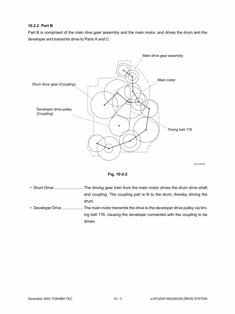
December 2002 TOSHIBA TEC 10 - 3 e-STUDIO160/200/250 DRIVE SYSTEM
10.2.2 Part B
Part B is comprised of the main dive gear assembly and the main motor, and drives the drum and the
developer and transmits drive to Parts A and C.
Fig. 10-2-2
• Drum Drive .......................... The driving gear train from the main motor drives the drum drive shaft
and coupling. The coupling part is fit to the drum, thereby driving the
drum.
• Developer Drive ................... The main motor transmits the drive to the developer drive pulley via tim-
ing belt 176, causing the developer connected with the coupling to be
driven.
10-2-2 PPS2
Main drive gear assembly
Timing belt 176
Developer drive pulley
(Coupling)
Drum drive gear (Coupling)
Main motor
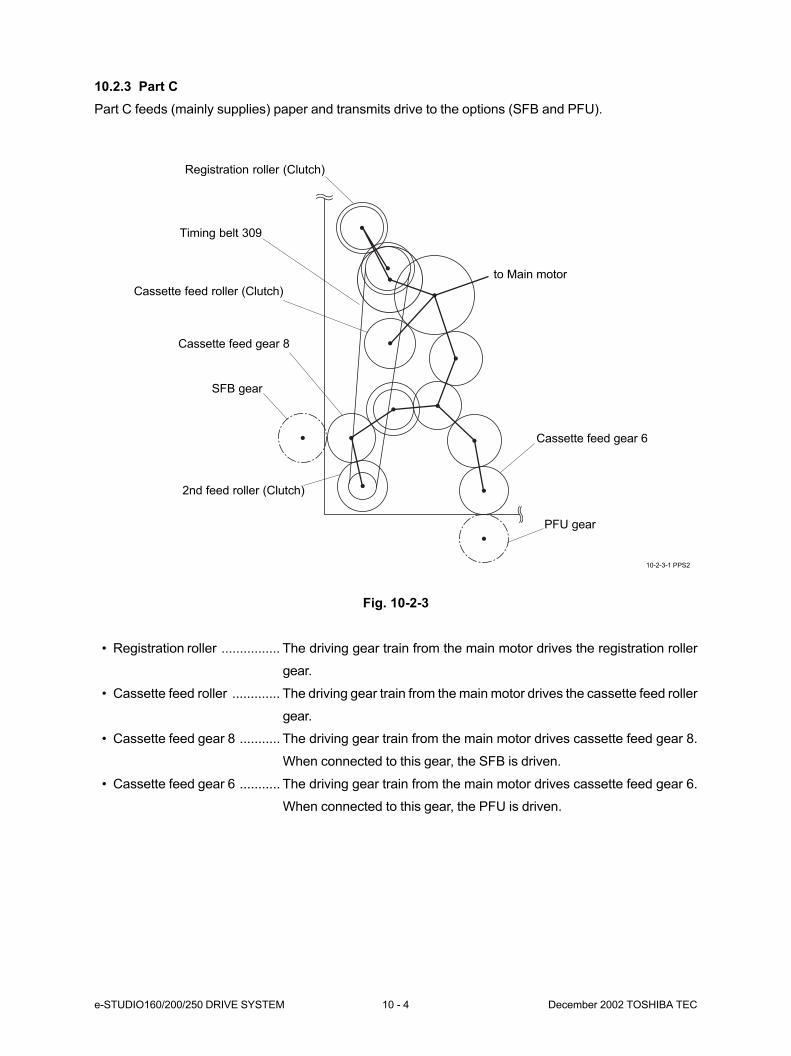
e-STUDIO160/200/250 DRIVE SYSTEM 10 - 4 December 2002 TOSHIBA TEC
10.2.3 Part C
Part C feeds (mainly supplies) paper and transmits drive to the options (SFB and PFU).
Fig. 10-2-3
• Registration roller ................ The driving gear train from the main motor drives the registration roller
gear.
• Cassette feed roller ............. The driving gear train from the main motor drives the cassette feed roller
gear.
• Cassette feed gear 8 ........... The driving gear train from the main motor drives cassette feed gear 8.
When connected to this gear, the SFB is driven.
• Cassette feed gear 6 ........... The driving gear train from the main motor drives cassette feed gear 6.
When connected to this gear, the PFU is driven.
10-2-3-1 PPS2
Registration roller (Clutch)
to Main motor
Cassette feed gear 6
PFU gear
2nd feed roller (Clutch)
SFB gear
Cassette feed roller (Clutch)
Timing belt 309
Cassette feed gear 8
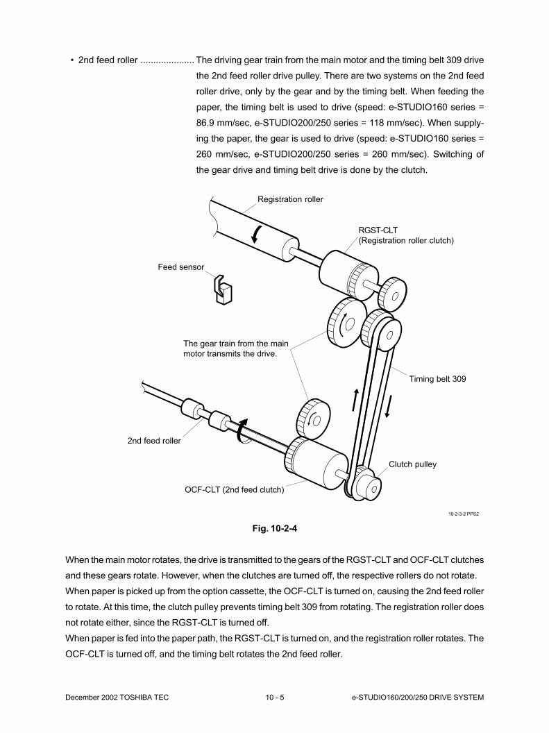
December 2002 TOSHIBA TEC 10 - 5 e-STUDIO160/200/250 DRIVE SYSTEM
• 2nd feed roller ..................... The driving gear train from the main motor and the timing belt 309 drive
the 2nd feed roller drive pulley. There are two systems on the 2nd feed
roller drive, only by the gear and by the timing belt. When feeding the
paper, the timing belt is used to drive (speed: e-STUDIO160 series =
86.9 mm/sec, e-STUDIO200/250 series = 118 mm/sec). When supply-
ing the paper, the gear is used to drive (speed: e-STUDIO160 series =
260 mm/sec, e-STUDIO200/250 series = 260 mm/sec). Switching of
the gear drive and timing belt drive is done by the clutch.
Fig. 10-2-4
When the main motor rotates, the drive is transmitted to the gears of the RGST-CLT and OCF-CLT clutches
and these gears rotate. However, when the clutches are turned off, the respective rollers do not rotate.
When paper is picked up from the option cassette, the OCF-CLT is turned on, causing the 2nd feed roller
to rotate. At this time, the clutch pulley prevents timing belt 309 from rotating. The registration roller does
not rotate either, since the RGST-CLT is turned off.
When paper is fed into the paper path, the RGST-CLT is turned on, and the registration roller rotates. The
OCF-CLT is turned off, and the timing belt rotates the 2nd feed roller.
10-2-3-2 PPS2
Registration roller
RGST-CLT
(Registration roller clutch)
Timing belt 309
Clutch pulley
OCF-CLT (2nd feed clutch)
2nd feed roller
The gear train from the main
motor transmits the drive.
Feed sensor

e-STUDIO160/200/250 DRIVE SYSTEM 10 - 6 December 2002 TOSHIBA TEC
10.3 Disassembly and Replacement
[A] Main drive gear assembly
1. If a STP (KK-1600) is attached to the copier,
disconnect the power cable.
2. Detach the manual pocket.
3. If a Finisher (MJ-1011) is attached to the copier,
detach the finisher plate and junction block.
4. If a JSP (MJ-5001) or OCT (MJ-5002) is at-
tached to the copier, detach it.
5. Detach the toner cartridge and the process unit.
6. Detach rear cover. (See Fig. 2-6-1)
7. Detach ozone cover. (See Fig. 2-6-9)
8. Detach paper tray cover. (See Fig. 2-6-10)
9. Remove PC I/F PWA. (See Fig. 2-6-28)
10. Remove high voltage power supply.
(See Fig. 2-6-29 and 2-6-30)
11. Release the spring.
12. Remove 2 screws, release the timing belt 309,
and remove cassette feed gear 2 assembly.
029
030-2
030-1
Fig. 10-3-1
15. Remove 2 screws.
13. If an ADU (MD-0101) is attached to the copier,
open it.
14. Open side cover.
Fig. 10-3-2
Fig. 10-3-3
Spring
Timing belt 309
Screw
Cassette feed
gear 2 assembly
Side cover
Screw
Drum drive shaft
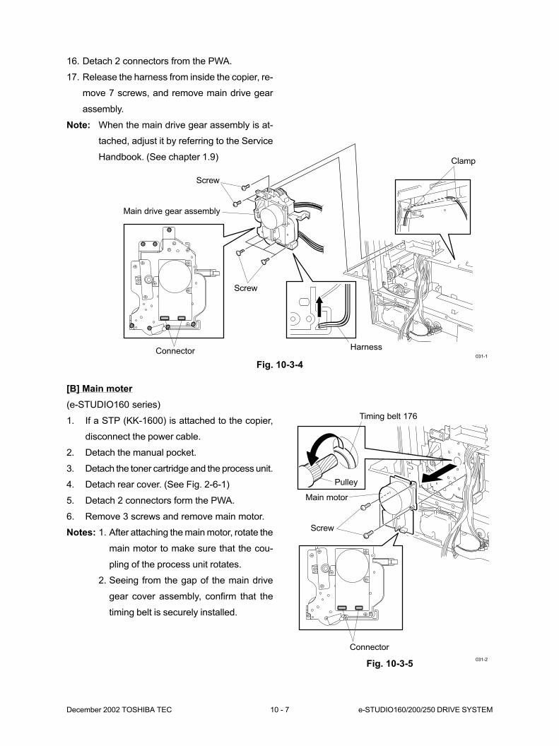
December 2002 TOSHIBA TEC 10 - 7 e-STUDIO160/200/250 DRIVE SYSTEM
031-1
Fig. 10-3-4
Screw
Clamp
Main drive gear assembly
HarnessConnector
Screw
031-2
Fig. 10-3-5
16. Detach 2 connectors from the PWA.
17. Release the harness from inside the copier, re-
move 7 screws, and remove main drive gear
assembly.
Note: When the main drive gear assembly is at-
tached, adjust it by referring to the Service
Handbook. (See chapter 1.9)
Screw
Pulley
Timing belt 176
Main motor
Connector
[B] Main moter
(e-STUDIO160 series)
1. If a STP (KK-1600) is attached to the copier,
disconnect the power cable.
2. Detach the manual pocket.
3. Detach the toner cartridge and the process unit.
4. Detach rear cover. (See Fig. 2-6-1)
5. Detach 2 connectors form the PWA.
6. Remove 3 screws and remove main motor.
Notes: 1. After attaching the main motor, rotate the
main motor to make sure that the cou-
pling of the process unit rotates.
2. Seeing from the gap of the main drive
gear cover assembly, confirm that the
timing belt is securely installed.
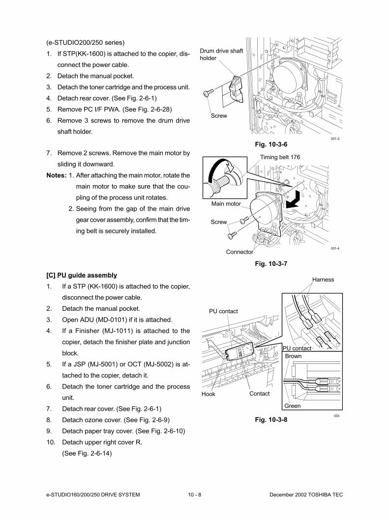
e-STUDIO160/200/250 DRIVE SYSTEM 10 - 8 December 2002 TOSHIBA TEC
033
Fig. 10-3-8
Hook
PU contact
Contact
Harness
PU contact
Brown
Green
[C] PU guide assembly
1. If a STP (KK-1600) is attached to the copier,
disconnect the power cable.
2. Detach the manual pocket.
3. Open ADU (MD-0101) if it is attached.
4. If a Finisher (MJ-1011) is attached to the
copier, detach the finisher plate and junction
block.
5. If a JSP (MJ-5001) or OCT (MJ-5002) is at-
tached to the copier, detach it.
6. Detach the toner cartridge and the process
unit.
7. Detach rear cover. (See Fig. 2-6-1)
8. Detach ozone cover. (See Fig. 2-6-9)
9. Detach paper tray cover. (See Fig. 2-6-10)
10. Detach upper right cover R.
(See Fig. 2-6-14)
(e-STUDIO200/250 series)
1. If STP(KK-1600) is attached to the copier, dis-
connect the power cable.
2. Detach the manual pocket.
3. Detach the toner cartridge and the process unit.
4. Detach rear cover. (See Fig. 2-6-1)
5. Remove PC I/F PWA. (See Fig. 2-6-28)
6. Remove 3 screws to remove the drum drive
shaft holder.
Fig. 10-3-6
7. Remove 2 screws. Remove the main motor by
sliding it downward.
Notes: 1. After attaching the main motor, rotate the
main motor to make sure that the cou-
pling of the process unit rotates.
2. Seeing from the gap of the main drive
gear cover assembly, confirm that the tim-
ing belt is securely installed.
Fig. 10-3-7
031-3
031-4
Screw
Drum drive shaft
holder
Screw
Timing belt 176
Connector
Main motor
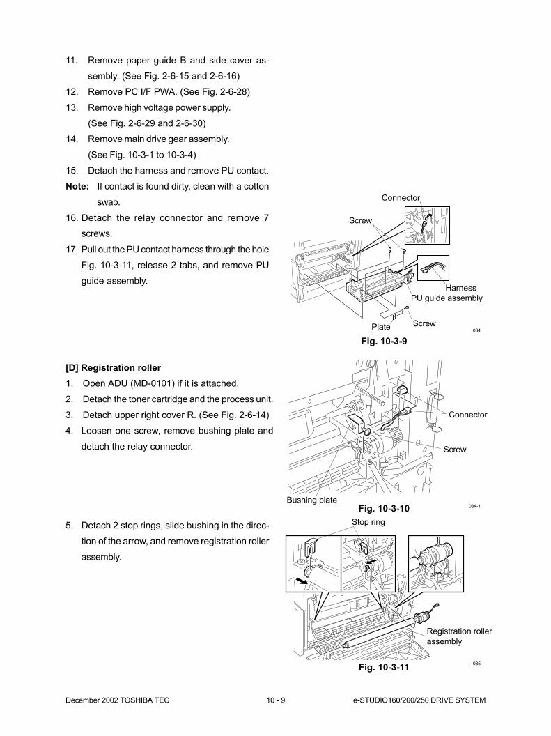
December 2002 TOSHIBA TEC 10 - 9 e-STUDIO160/200/250 DRIVE SYSTEM
034
Fig. 10-3-9
Connector
Screw
PU guide assembly
Harness
Screw
Plate
11. Remove paper guide B and side cover as-
sembly. (See Fig. 2-6-15 and 2-6-16)
12. Remove PC I/F PWA. (See Fig. 2-6-28)
13. Remove high voltage power supply.
(See Fig. 2-6-29 and 2-6-30)
14. Remove main drive gear assembly.
(See Fig. 10-3-1 to 10-3-4)
15. Detach the harness and remove PU contact.
Note: If contact is found dirty, clean with a cotton
swab.
16. Detach the relay connector and remove 7
screws.
17. Pull out the PU contact harness through the hole
Fig. 10-3-11, release 2 tabs, and remove PU
guide assembly.
034-1Fig. 10-3-10
Connector
Bushing plate
Screw
[D] Registration roller
1. Open ADU (MD-0101) if it is attached.
2. Detach the toner cartridge and the process unit.
3. Detach upper right cover R. (See Fig. 2-6-14)
4. Loosen one screw, remove bushing plate and
detach the relay connector.
5. Detach 2 stop rings, slide bushing in the direc-
tion of the arrow, and remove registration roller
assembly.
Fig. 10-3-11035
Registration roller
assembly
Stop ring
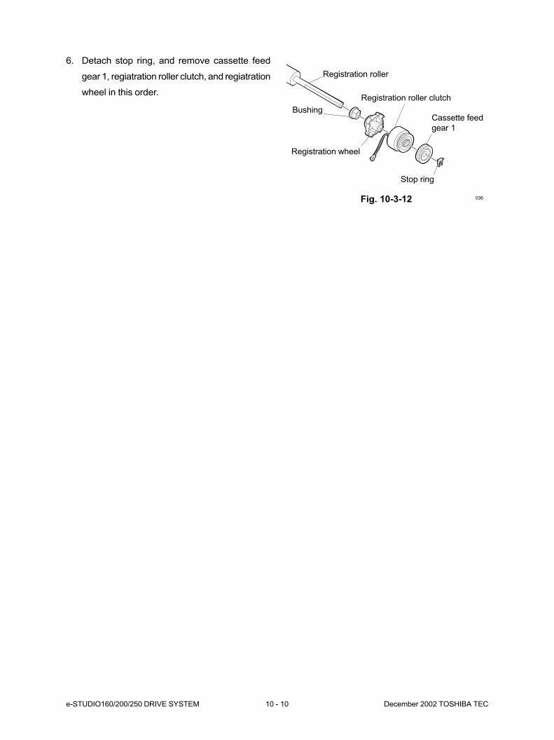
e-STUDIO160/200/250 DRIVE SYSTEM 10 - 10 December 2002 TOSHIBA TEC
036
6. Detach stop ring, and remove cassette feed
gear 1, regiatration roller clutch, and regiatration
wheel in this order.
Registration roller
Registration roller clutch
BushingCassette feed
gear 1
Registration wheel
Stop ring
Fig. 10-3-12
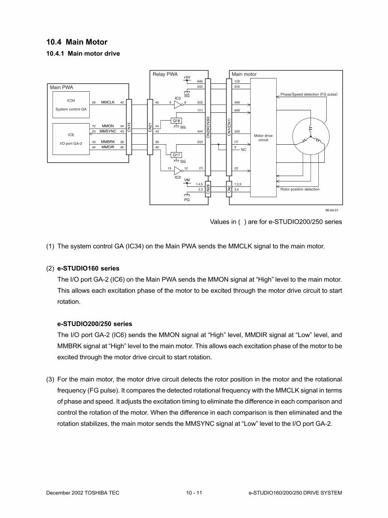
December 2002 TOSHIBA TEC 10 - 11 e-STUDIO160/200/250 DRIVE SYSTEM
10.4 Main Motor
10.4.1 Main motor drive
(1) The system control GA (IC34) on the Main PWA sends the MMCLK signal to the main motor.
(2) e-STUDIO160 series
The I/O port GA-2 (IC6) on the Main PWA sends the MMON signal at “High” level to the main motor.
This allows each excitation phase of the motor to be excited through the motor drive circuit to start
rotation.
e-STUDIO200/250 series
The I/O port GA-2 (IC6) sends the MMON signal at “High” level, MMDIR signal at “Low” level, and
MMBRK signal at “High” level to the main motor. This allows each excitation phase of the motor to be
excited through the motor drive circuit to start rotation.
(3) For the main motor, the motor drive circuit detects the rotor position in the motor and the rotational
frequency (FG pulse). It compares the detected rotational frequency with the MMCLK signal in terms
of phase and speed. It adjusts the excitation timing to eliminate the difference in each comparison and
control the rotation of the motor. When the difference in each comparison is then eliminated and the
rotation stabilizes, the main motor sends the MMSYNC signal at “Low” level to the I/O port GA-2.
IC34
System control GA
Motor drivecircuit
NC
IC6
I/O port GA-2
Main PWA
Relay PWA Main motor
Q18
IC3
IC3
MMON
MMCLK
MMSYNC
MMBRKMMDIR
Q17
+5V
SG
SG
SG
2(2)
4(4)
1(1)
3(3)
5(5)
6(6)
(7)
(7)
5
3(5)
6(8)
4(6)
2(4)
1(3)
(2)
1,4,5
2,3
1,2,5
3,4
VM
PG
CN
1(C
N1)
CN
2
CN
29( C
N30
)C
N28
CN
21
CN
15
Phase/Speed detection (FG pulse)
Rotor position detection
40
39
43
44
42
44
43
23
72
29
40
39
43
44
42 5
13
6
12
06-04-01
Values in ( ) are for e-STUDIO200/250 series
e-STUDIO160/200/250 DRIVE SYSTEM 10 - 12 December 2002 TOSHIBA TEC
(4) e-STUDIO160 series
To stop the rotation, the I/O port GA-2 turns the MMON signal to “Low” level, thereby stopping the
main motor.
e-STUDIO200/250 series
To stop the rotation, the I/O port GA-2 turns the MMBRK signal to “High” level, thereby braking the
rotation of the main motor. Then, the I/O port GA-2 turns the MMON signal to “Low” level to stop the
main motor.
10.4.2 Control signals
(1) MMCLK signal
Reference clock signal for rotational speed.
(2) MMDIR signal (e-STUDIO200/250 series)
Rotational direction setting signal.
“Low” level: Rotates counterclockwise as viewed from the output shaft.
“High” level: Rotates clockwise as viewed from the output shaft.
(3) MMBRK signal (e-STUDIO200/250 series)
Rotational brake signal.
“Low” level: Brake ON
“High” level: Brake OFF
(4) MMON signal
ON/OFF control signal for main motor.
“Low” level: OFF
“High” level: ON
(5) MMSYNC signal
Detection signal for rotational state.
“Low” level: Rotation at constant speed
“High” level: Rotation at non-constant speed
11. DRUM-RELATED SECTION .................... 11-1
11.1 General Description .................................................................................. 11-1
11.2 Construction .............................................................................................. 11-1
11.3 Drive Description....................................................................................... 11-2
11.4 Function of Each Part ............................................................................... 11-3
11.5 High Voltage Output Control Circuit .......................................................... 11-4
11.5.1 Outline .......................................................................................... 11-4
11.5.2 Control method............................................................................. 11-4
11.6 Disassembly and Replacement ................................................................ 11-7
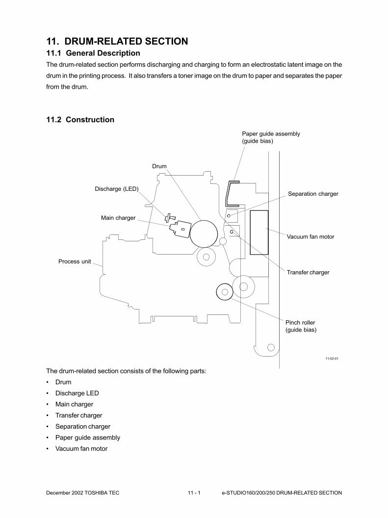
December 2002 TOSHIBA TEC 11 - 1 e-STUDIO160/200/250 DRUM-RELATED SECTION
11. DRUM-RELATED SECTION11.1 General Description
The drum-related section performs discharging and charging to form an electrostatic latent image on the
drum in the printing process. It also transfers a toner image on the drum to paper and separates the paper
from the drum.
11.2 Construction
11-02-01
Main charger
Separation charger
Transfer charger
Drum
Discharge (LED)
Process unit
Paper guide assembly
(guide bias)
Vacuum fan motor
Pinch roller
(guide bias)
The drum-related section consists of the following parts:
• Drum
• Discharge LED
• Main charger
• Transfer charger
• Separation charger
• Paper guide assembly
• Vacuum fan motor
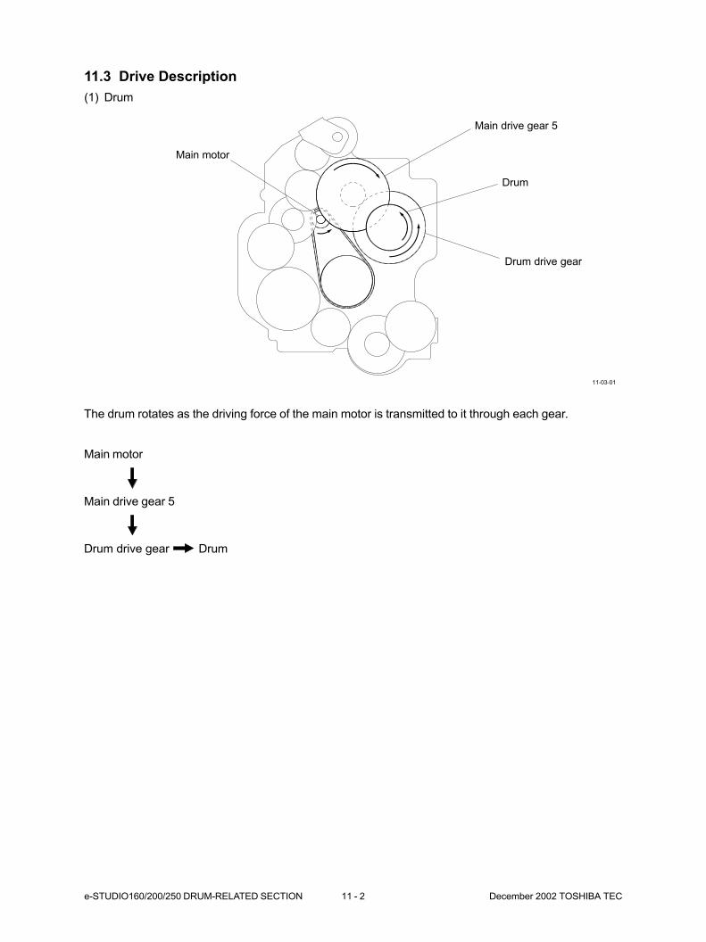
e-STUDIO160/200/250 DRUM-RELATED SECTION 11 - 2 December 2002 TOSHIBA TEC
11.3 Drive Description
(1) Drum
11-03-01
Main motor
Drum drive gear
Drum
Main drive gear 5
The drum rotates as the driving force of the main motor is transmitted to it through each gear.
Main motor
Main drive gear 5
Drum drive gear Drum
December 2002 TOSHIBA TEC 11 - 3 e-STUDIO160/200/250 DRUM-RELATED SECTION
11.4 Function of Each Part
(1) Drum
The drum comprises a drum-shaped, Aluminum base coated with an organic photosensitive element
(photoconductor) film. The principle of “Photoconductivity” indicates that insulating properties of the
material are evidenced in the dark. Likewise, its conductive properties are evidenced in the presence
of light.
(2) Main charger
Applies a negative electrostatic charge to the drum (through a high-voltage transformer). When high
voltage is applied to this charger wire, the air around the wire is ionized (electrostatically charged).
The ionized air is attracted to the drum’s surface. This phenomenon is referred to as “corona dis-
charged.” In the dark, the surface of the drum is negatively (minus) charged using the principle of
corona discharge.
(3) Discharge LED
Lower the electrical resistance of the photosensitive surface that was left over after the exposure and
transfer processes. The discharge LED has two effects, a cleaning effect and “pre-exposure” effect.
The cleaning effect neutralizes and eliminates the residual charge on the surface of the photosensitive
element while the pre-exposure effect maintains a fixed photosensitive surface potential before the
charging process is again initiated.
(4) Transfer charger
Transfer the toner on the drum to the copy paper. When high voltage is applied to this charger wire, the
air around the wire is ionized (electrostatically charged). The ionized air is attracted to the backside of
the copy paper. This phenomenon is referred to as “corona discharged.” The backside of the copy
paper is positively (plus) charged using the principle of corona discharge.
(5) Paper guide assembly
Positive (plus) bias voltage is applied to the guide to prevent that the of translatability is lowered under
the condition such as high humidity.
(6) Separation charger
Separates the copy paper with toner from the drum. When high voltage is applied to this charger wire,
the air around the wire is ionized (electrostatically charged). The ionized air is attracted to the back-
side of the copy paper. This phenomenon is referred to as “corona discharged.” The backside of the
copy paper is negatively (minus) charged using the principle of corona discharge. The electrostatic
attraction between the paper and the drum weakens.
(7) Vacuum fan motor
Works to help separation of copy paper from the drum surface by sucking the air form the back side of
the paper.
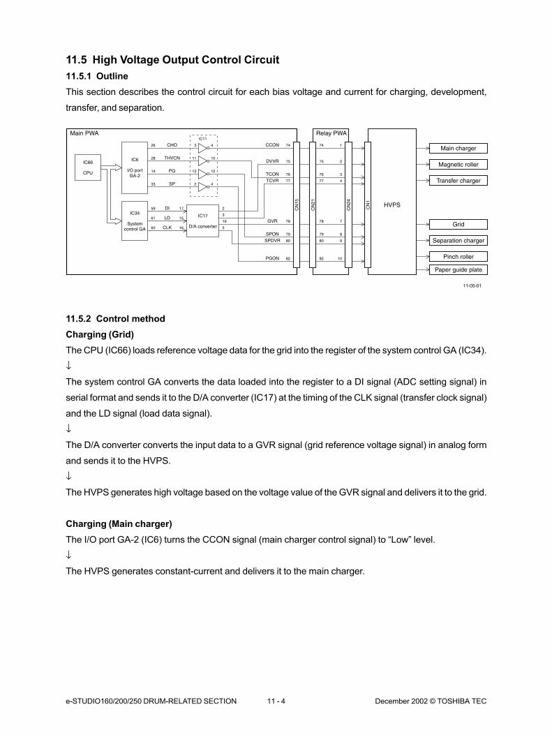
e-STUDIO160/200/250 DRUM-RELATED SECTION 11 - 4 December 2002 © TOSHIBA TEC
11.5 High Voltage Output Control Circuit
11.5.1 Outline
This section describes the control circuit for each bias voltage and current for charging, development,
transfer, and separation.
11.5.2 Control method
Charging (Grid)
The CPU (IC66) loads reference voltage data for the grid into the register of the system control GA (IC34).
↓
The system control GA converts the data loaded into the register to a DI signal (ADC setting signal) in
serial format and sends it to the D/A converter (IC17) at the timing of the CLK signal (transfer clock signal)
and the LD signal (load data signal).
↓
The D/A converter converts the input data to a GVR signal (grid reference voltage signal) in analog form
and sends it to the HVPS.
↓
The HVPS generates high voltage based on the voltage value of the GVR signal and delivers it to the grid.
Charging (Main charger)
The I/O port GA-2 (IC6) turns the CCON signal (main charger control signal) to “Low” level.
↓
The HVPS generates constant-current and delivers it to the main charger.
IC6
I/O portGA-2
IC34
Systemcontrol GA
IC66
CPU
Main PWA
CCON 1
4
74 74CHO 3 426
IC11
TCON 376 76
THVCN 11 1028
SPON 879 79
PG 13 1214
PGON 1082 82
SP 2 433
DVVR 275 75
DI 1759
TCVR 77 77
LD 1561GVR 778 78
CLK 1660
SPDVR 980 80
2
3
19
5
IC17
D/A converter
Relay PWA
CN
24
CN
21 HVPS
Main charger
CN
1
CN
15
Magnetic roller
Transfer charger
Grid
Separation charger
Paper guide plate
Pinch roller
11-05-01

December 2002 © TOSHIBA TEC 11 - 5 e-STUDIO160/200/250 DRUM-RELATED SECTION
Development (Magnetic roller)
The CPU (IC66) loads reference voltage data for development bias into the register of the system control
GA (IC34).
↓
The system control GA converts the data loaded into the register to a DI signal (ADC setting signal) in
serial format and sends it to the D/A converter (IC17) at the timing of the CLK signal (transfer clock signal)
and the LD signal (load data signal).
↓
The D/A converter converts the input data to a DVVR signal (development bias reference voltage signal)
in analog form and sends it to the HVPS.
↓
The HVPS generates high voltage based on the voltage value of the DVVR signal and delivers it to the
magnetic roller.
There are the following two cases where high voltage is delivered to the magnetic roller: the delivery of
positive voltage (during initial operation) and the delivery of negative voltage (during printing operation).
Only during the delivery of positive voltage, the development bias voltage is delivered or cut off synchro-
nizing with the timing of the SPON signal (separation charger control signal). When the SPON signal is at
“Low” level, the positive voltage is delivered.
Transfer (Transfer charger)
The CPU (IC66) loads reference voltage data for transfer bias into the register of the system control GA
(IC34).
↓
The system control GA converts the data loaded into the register to a DI signal (ADC setting signal) in
serial format and sends it to the D/A converter (IC17) at the timing of the CLK signal (transfer clock signal)
and the LD signal (load data signal).
↓
The D/A converter converts the input data to a TCVR signal (transfer bias reference voltage signal) in
analog form and sends it to the HVPS.
↓
The I/O port GA-2 (IC6) turns the TCON signal (transfer charger control signal) to “Low” level.
↓
The HVPS generates current based on the voltage value of the TCVR and delivers it to the transfer
charger.

e-STUDIO160/200/250 DRUM-RELATED SECTION 11 - 6 December 2002 © TOSHIBA TEC
Separation (Separation charger)
The CPU (IC66) loads reference voltage data for separation bias into the register of the system control GA
(IC34).
↓
The system control GA converts the data loaded into the register to a DI signal (ADC setting signal) in
serial format and sends it to the D/A converter (IC17) at the timing of the CLK signal (transfer clock signal)
and LD signal (load data signal).
↓
The D/A converter converts the input data to a SPDVR signal (separation bias reference voltage signal) in
analog form and sends it to the HVPS.
↓
The I/O port GA-2 (IC6) turns the SPON signal (separation charger control signal) to “Low” level.
↓
The HVPS generates current based on the voltage value of the SPDVR signal and delivers it to the
separation charger.
Guide bias (Paper guide plate / Pinch roller)
The I/O port GA-2 (IC6) turns the SPON signal (separation charger control signal) to “Low” level.
↓
The I/O port GA-2 turns the PGON signal (paper guide plate/pinch roller control signal) to “Low” level.
↓
The HVPS generates constant-voltage and delivers it to the paper guide plate/pinch roller.
High voltage to the paper guide plate/pinch roller is delivered or cut off synchronizing with the timing of the
SPON signal (separation charger control signal). When the SPON signal is at “Low” level, the voltage is
delivered.
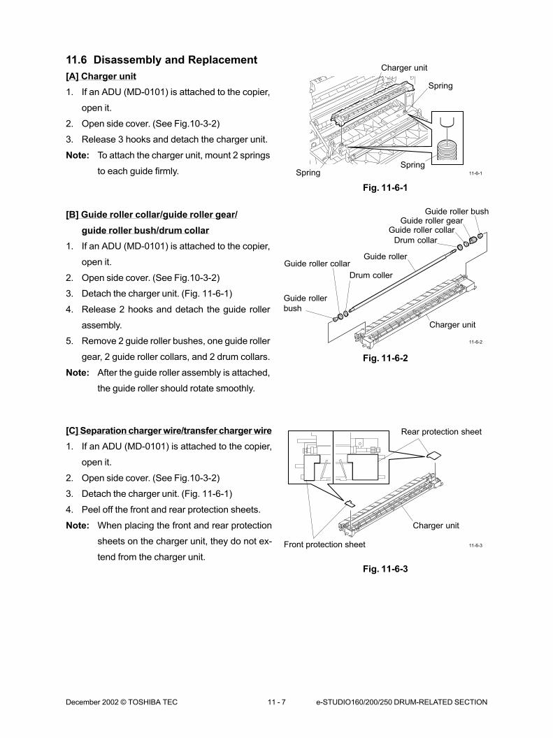
December 2002 © TOSHIBA TEC 11 - 7 e-STUDIO160/200/250 DRUM-RELATED SECTION
11.6 Disassembly and Replacement
[A] Charger unit
1. If an ADU (MD-0101) is attached to the copier,
open it.
2. Open side cover. (See Fig.10-3-2)
3. Release 3 hooks and detach the charger unit.
Note: To attach the charger unit, mount 2 springs
to each guide firmly.
Fig. 11-6-1
[B] Guide roller collar/guide roller gear/
guide roller bush/drum collar
1. If an ADU (MD-0101) is attached to the copier,
open it.
2. Open side cover. (See Fig.10-3-2)
3. Detach the charger unit. (Fig. 11-6-1)
4. Release 2 hooks and detach the guide roller
assembly.
5. Remove 2 guide roller bushes, one guide roller
gear, 2 guide roller collars, and 2 drum collars.
Note: After the guide roller assembly is attached,
the guide roller should rotate smoothly.
Fig. 11-6-2
[C] Separation charger wire/transfer charger wire
1. If an ADU (MD-0101) is attached to the copier,
open it.
2. Open side cover. (See Fig.10-3-2)
3. Detach the charger unit. (Fig. 11-6-1)
4. Peel off the front and rear protection sheets.
Note: When placing the front and rear protection
sheets on the charger unit, they do not ex-
tend from the charger unit.
Fig. 11-6-3
11-6-1
11-6-2
11-6-3
Charger unit
SpringSpring
Spring
Charger unit
Guide roller
bush
Guide roller collar
Drum coller
Guide roller
Drum collar
Guide roller collarGuide roller gear
Guide roller bush
Rear protection sheet
Front protection sheet
Charger unit
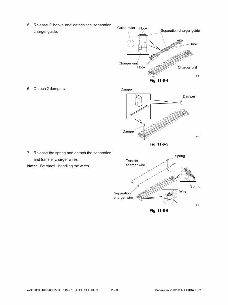
e-STUDIO160/200/250 DRUM-RELATED SECTION 11 - 8 December 2002 © TOSHIBA TEC
5. Release 9 hooks and detach the separation
charger guide.
Fig. 11-6-4
6. Detach 2 dampers.
Fig. 11-6-5
7. Release the spring and detach the separation
and transfer charger wires.
Note: Be careful handling the wires.
11-6-4
11-6-5
11-6-6
Charger unit
Transfer
charger wire
Wire
Spring
Spring
Separation
charger wire
Damper
Damper
Damper
Guide rollerSeparation charger guide
Charger unitHook
Hook
Hook
Fig. 11-6-6
12. DEVELOPER SECTION ........................... 12-1
12.1 General Description .................................................................................. 12-1
12.2 Construction .............................................................................................. 12-1
12.3 Drive Description....................................................................................... 12-2
12.4 Function of Each Part ............................................................................... 12-5
12.5 Toner Control Circuit ................................................................................. 12-6
12.5.1 Outline .......................................................................................... 12-6
12.5.2 Toner empty detection circuit........................................................ 12-6
12.5.3 Toner supply motor ....................................................................... 12-7
12.6 Disassembly and Replacement ................................................................ 12-8
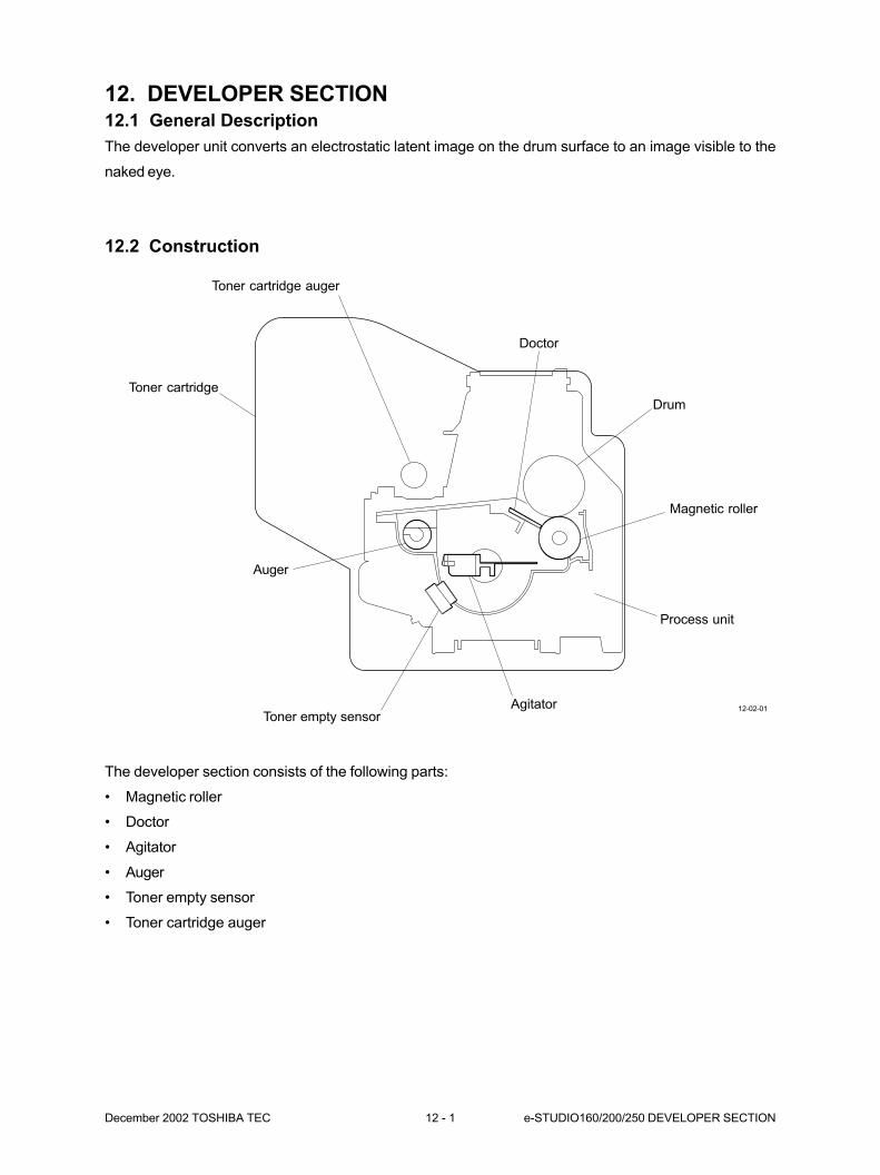
December 2002 TOSHIBA TEC 12 - 1 e-STUDIO160/200/250 DEVELOPER SECTION
12. DEVELOPER SECTION12.1 General Description
The developer unit converts an electrostatic latent image on the drum surface to an image visible to the
naked eye.
12.2 Construction
The developer section consists of the following parts:
• Magnetic roller
• Doctor
• Agitator
• Auger
• Toner empty sensor
• Toner cartridge auger
12-02-01
Toner empty sensor
Doctor
Drum
Magnetic roller
Agitator
Toner cartridge auger
Auger
Toner cartridge
Process unit
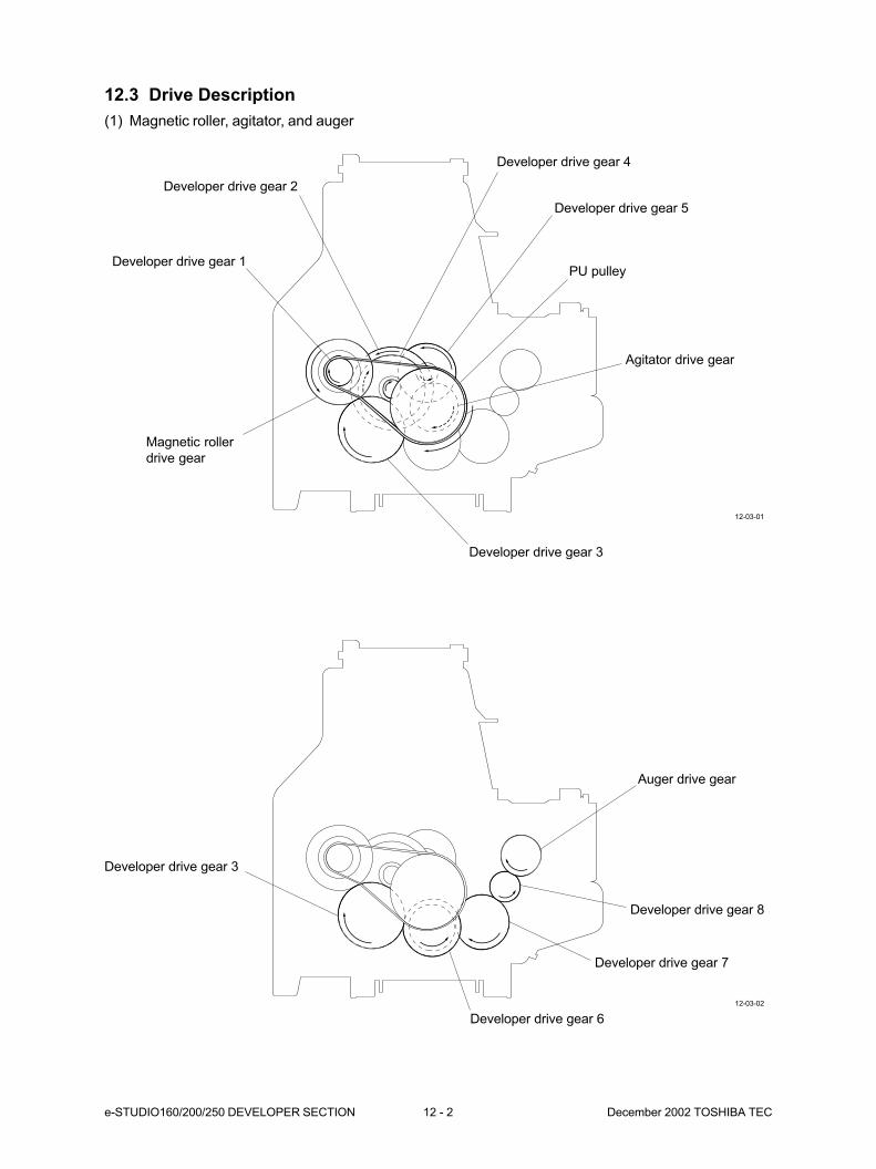
e-STUDIO160/200/250 DEVELOPER SECTION 12 - 2 December 2002 TOSHIBA TEC
12.3 Drive Description
(1) Magnetic roller, agitator, and auger
12-03-01
12-03-02
Magnetic roller
drive gear
Developer drive gear 4
Developer drive gear 5
PU pulley
Agitator drive gear
Developer drive gear 3
Developer drive gear 2
Developer drive gear 1
Developer drive gear 6
Developer drive gear 7
Developer drive gear 8
Developer drive gear 3
Auger drive gear
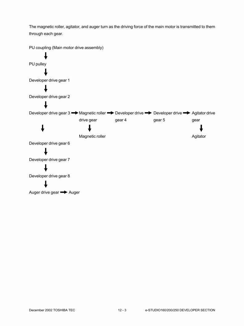
December 2002 TOSHIBA TEC 12 - 3 e-STUDIO160/200/250 DEVELOPER SECTION
The magnetic roller, agitator, and auger turn as the driving force of the main motor is transmitted to them
through each gear.
PU coupling (Main motor drive assembly)
PU pulley
Developer drive gear 1
Developer drive gear 2
Developer drive gear 3 Magnetic roller Developer drive Developer drive Agitator drive
drive gear gear 4 gear 5 gear
Magnetic roller Agitator
Developer drive gear 6
Developer drive gear 7
Developer drive gear 8
Auger drive gear Auger
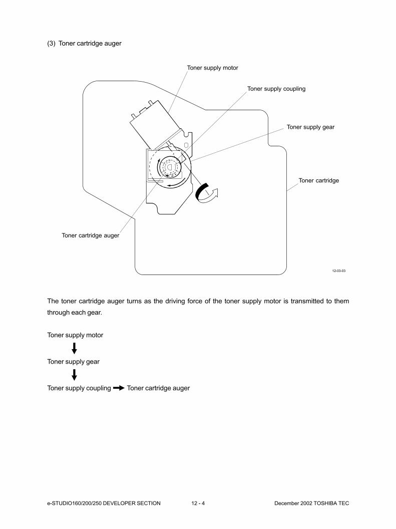
e-STUDIO160/200/250 DEVELOPER SECTION 12 - 4 December 2002 TOSHIBA TEC
(3) Toner cartridge auger
The toner cartridge auger turns as the driving force of the toner supply motor is transmitted to them
through each gear.
Toner supply motor
Toner supply gear
Toner supply coupling Toner cartridge auger
12-03-03
Toner cartridge auger
Toner supply gear
Toner supply coupling
Toner supply motor
Toner cartridge
December 2002 TOSHIBA TEC 12 - 5 e-STUDIO160/200/250 DEVELOPER SECTION
12.4 Function of Each Part
(1) Magnetic roller
Magnetic roller is made of aluminum, with magnets positioned inside it. By using the magnetic force,
the developer material is attracted (because the carrier is made of iron powder), forming magnetic
lines of force shaped like a brush. Further, magnets are secured, and only the sleeves around mag-
netic roller rotate. Through this rotation, the magnetic brush of the magnetic roller sweeps the surface
of the photosensitive drum, enabling development.
(2) Doctor
The doctor makes the thickness of the toner layer on the magnetic roller surface as specified to allow
toner to pass between the magnetic roller and the drum.
(3) Agitator
The agitator supplies toner in the developer unit to the magnetic roller.
(4) Auger
The auger delivers the toner supplied from the toner kit to the developer unit.
(5) Toner empty sensor
The toner empty sensor detects the presence or absence of toner in the developer unit.
(6) Toner cartridge auger
The toner cartridge auger supplies toner in the toner cartridge to the developer unit. If the absence of
toner in the developer unit is detected by the toner sensor, the toner cartridge motor operates for a
fixed time. This allows the toner cartridge auger to turn and toner to be added to the developer unit
from the toner cartridge.
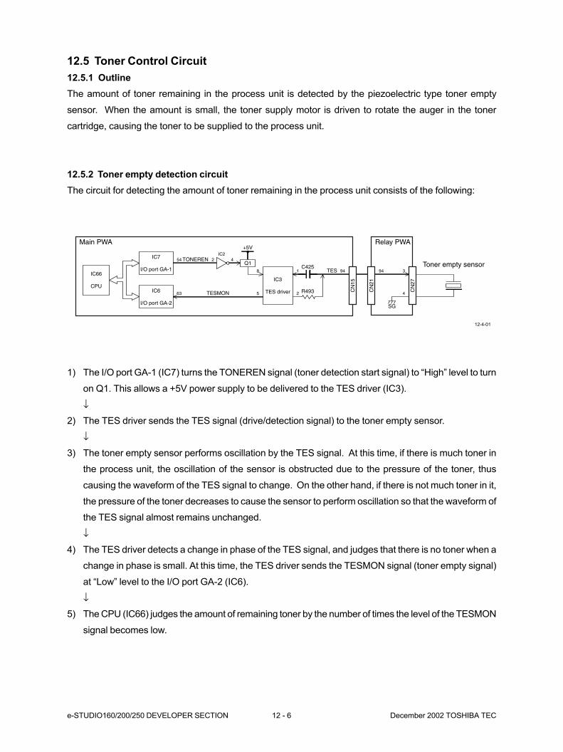
e-STUDIO160/200/250 DEVELOPER SECTION 12 - 6 December 2002 TOSHIBA TEC
12.5 Toner Control Circuit
12.5.1 Outline
The amount of toner remaining in the process unit is detected by the piezoelectric type toner empty
sensor. When the amount is small, the toner supply motor is driven to rotate the auger in the toner
cartridge, causing the toner to be supplied to the process unit.
12.5.2 Toner empty detection circuit
The circuit for detecting the amount of toner remaining in the process unit consists of the following:
1) The I/O port GA-1 (IC7) turns the TONEREN signal (toner detection start signal) to “High” level to turn
on Q1. This allows a +5V power supply to be delivered to the TES driver (IC3).
↓
2) The TES driver sends the TES signal (drive/detection signal) to the toner empty sensor.
↓
3) The toner empty sensor performs oscillation by the TES signal. At this time, if there is much toner in
the process unit, the oscillation of the sensor is obstructed due to the pressure of the toner, thus
causing the waveform of the TES signal to change. On the other hand, if there is not much toner in it,
the pressure of the toner decreases to cause the sensor to perform oscillation so that the waveform of
the TES signal almost remains unchanged.
↓
4) The TES driver detects a change in phase of the TES signal, and judges that there is no toner when a
change in phase is small. At this time, the TES driver sends the TESMON signal (toner empty signal)
at “Low” level to the I/O port GA-2 (IC6).
↓
5) The CPU (IC66) judges the amount of remaining toner by the number of times the level of the TESMON
signal becomes low.
12-4-01
IC3
TES driver
Main PWA Relay PWA
Toner empty sensorTES
C425
R493
SG
3
4
948 1
2
CN
27
CN
21
CN
15
94
TESMON
TONEREN
563
Q1
+5V
2 454IC2
IC7
I/O port GA-1
IC6
I/O port GA-2
IC66
CPU
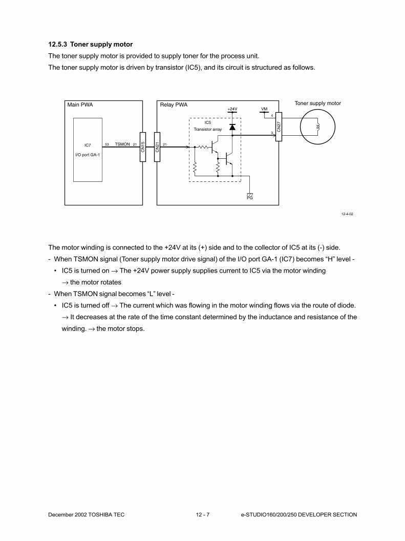
December 2002 TOSHIBA TEC 12 - 7 e-STUDIO160/200/250 DEVELOPER SECTION
12.5.3 Toner supply motor
The toner supply motor is provided to supply toner for the process unit.
The toner supply motor is driven by transistor (IC5), and its circuit is structured as follows.
The motor winding is connected to the +24V at its (+) side and to the collector of IC5 at its (-) side.
- When TSMON signal (Toner supply motor drive signal) of the I/O port GA-1 (IC7) becomes “H” level -
• IC5 is turned on → The +24V power supply supplies current to IC5 via the motor winding
→ the motor rotates
- When TSMON signal becomes “L” level -
• IC5 is turned off → The current which was flowing in the motor winding flows via the route of diode.
→ It decreases at the rate of the time constant determined by the inductance and resistance of the
winding. → the motor stops.
IC7
I/O port GA-1
IC5
Transistor array
Main PWA Relay PWA Toner supply motor
TSMON
3
4
2153
CN
27
CN
21
CN
15 21
VM+24V
PG
12-4-02
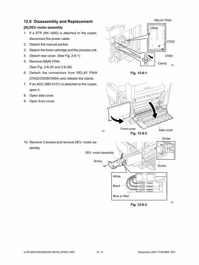
e-STUDIO160/200/250 DEVELOPER UNIT 12 - 8 December 2002 TOSHIBA TEC
084
083
082
RELAY PWA
Front cover
CN39
CN32
CN54
Clamp
Side cover
Screw
Screw
Screw
DEV. motor assembly
Fig. 12-6-1
7. If an ADU (MD-0101) is attached to the copier,
open it.
8. Open side cover.
9. Open front cover.
Fig. 12-6-2
10. Remove 3 screws and remove DEV. motor as-
sembly.
Fig. 12-6-3
White
Black
Blue or Red
12.6 Disassembly and Replacement
[A] DEV. motor assembly
1. If a STP (KK-1600) is attached to the copier,
disconnect the power cable.
2. Detach the manual pocket.
3. Detach the toner cartridge and the process unit.
4. Detach rear cover. (See Fig. 2-6-1)
5. Remove MAIN PWA.
(See Fig. 2-6-25 and 2-6-26)
6. Detach the connectors from RELAY PWA
(CN32/CN39/CN54) and release the clamp.
13. CLEANER SECTION................................ 13-1
13.1 General Description .................................................................................. 13-1
13.2 Construction .............................................................................................. 13-1
13.3 Drive Description....................................................................................... 13-2
13.4 Function of Each Part ............................................................................... 13-3

December 2002 © TOSHIBA TEC 13 - 1 e-STUDIO160/200/250 CLEANER SECTION
13. CLEANER SECTION
13.1 General Description
The cleaner unit removes the residual toner from the drum surface and carries it to the toner bag of the
toner cartridge.
13.2 Construction
The cleaner section consists of the following parts:
• Main blade
• Recovery blade
• Cleaner paddle
• Toner recovery auger
13-02-01
Toner recovery auger
Recovery blade
Drum
Main blade
Cleaner paddleToner cartridge
Process unit
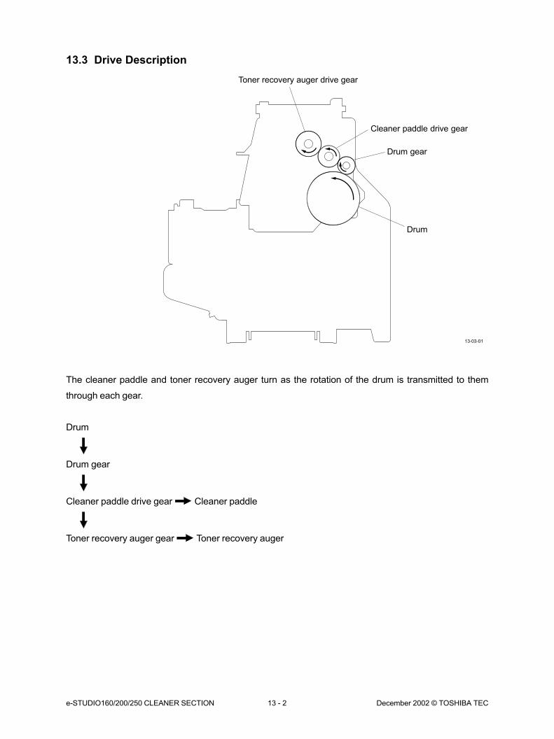
e-STUDIO160/200/250 CLEANER SECTION 13 - 2 December 2002 © TOSHIBA TEC
13.3 Drive Description
The cleaner paddle and toner recovery auger turn as the rotation of the drum is transmitted to them
through each gear.
Drum
Drum gear
Cleaner paddle drive gear Cleaner paddle
Toner recovery auger gear Toner recovery auger
13-03-01
Toner recovery auger drive gear
Drum
Cleaner paddle drive gear
Drum gear
December 2002 © TOSHIBA TEC 13 - 3 e-STUDIO160/200/250 CLEANER SECTION
13.4 Function of Each Part
(1) Main blade
Scrapes off residual toner on the drum surface. The blade is pushed against the drum at a constant
pressure by weight.
(2) Recovery blade
Catches the toner after it is scraped off by the main blade.
(3) Cleaner paddle
The cleaner paddle conveys the residual toner collected on the recovery blade to the toner recovery
auger.
(4) Toner recovery auger
Carries scrapped residual toner to the toner bag.
(5) Toner bag
Stores the scraped residual toner carried by the toner recovery auger.
14. FUSER UNIT/EXIT UNIT .......................... 14-1
14.1 General Description .................................................................................. 14-1
14.2 Construction .............................................................................................. 14-1
14.3 Drive Description....................................................................................... 14-2
14.4 Description of Operations ......................................................................... 14-3
14.4.1 Fuser unit ..................................................................................... 14-3
14.4.2 Exit unit ........................................................................................ 14-3
14.5 Functions of Each Part.............................................................................. 14-4
14.5.1 Fuser unit ..................................................................................... 14-4
14.5.2 Paper exit unit .............................................................................. 14-4
14.6 Heater Control Circuit ............................................................................... 14-6
14.6.1 Temperature detection section ..................................................... 14-6
14.6.2 Temperature detection by the thermistor ...................................... 14-9
14.7 Disassembly and Replacement ................................................................ 14-10
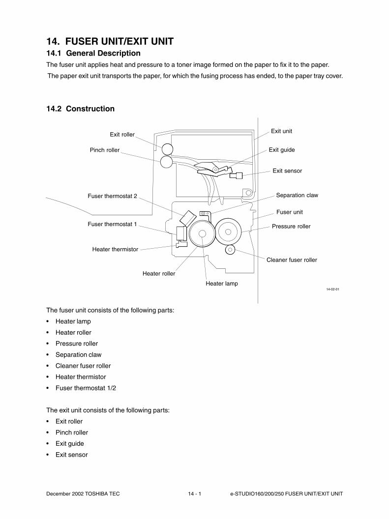
December 2002 TOSHIBA TEC 14 - 1 e-STUDIO160/200/250 FUSER UNIT/EXIT UNIT
14. FUSER UNIT/EXIT UNIT14.1 General DescriptionThe fuser unit applies heat and pressure to a toner image formed on the paper to fix it to the paper.
The paper exit unit transports the paper, for which the fusing process has ended, to the paper tray cover.
14.2 Construction
The fuser unit consists of the following parts:
• Heater lamp
• Heater roller
• Pressure roller
• Separation claw
• Cleaner fuser roller
• Heater thermistor
• Fuser thermostat 1/2
The exit unit consists of the following parts:
• Exit roller
• Pinch roller
• Exit guide
• Exit sensor
14-02-01
Heater roller
Exit unit
Exit guide
Exit sensor
Fuser unit
Pressure roller
Cleaner fuser roller
Heater lamp
Exit roller
Pinch roller
Fuser thermostat 1
Heater thermistor
Separation clawFuser thermostat 2
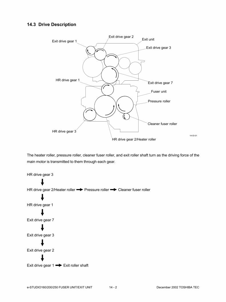
e-STUDIO160/200/250 FUSER UNIT/EXIT UNIT 14 - 2 December 2002 TOSHIBA TEC
14.3 Drive Description
The heater roller, pressure roller, cleaner fuser roller, and exit roller shaft turn as the driving force of the
main motor is transmitted to them through each gear.
HR drive gear 3
HR drive gear 2/Heater roller Pressure roller Cleaner fuser roller
HR drive gear 1
Exit drive gear 7
Exit drive gear 3
Exit drive gear 2
Exit drive gear 1 Exit roller shaft
14-03-01
HR drive gear 3
Exit drive gear 2Exit unit
Exit drive gear 3
Exit drive gear 7
Fuser unit
Pressure roller
Cleaner fuser roller
HR drive gear 2/Heater roller
Exit drive gear 1
HR drive gear 1

December 2002 TOSHIBA TEC 14 - 3 e-STUDIO160/200/250 FUSER UNIT/EXIT UNIT
14.4 Description of Operations
14.4.1 Fuser unit
The power of the main motor is transmitted to the gear of the fuser through the main drive gear assembly
to turn the heater roller. Since the pressure roller is pressed against the heater roller by the spring, it turns
by the power of the heater roller. Consequently, the paper is transported by the heater roller and pressure
roller.
When the paper is transported by the fuser unit, electric power is supplied to the heater lamp inside the
heater roller so that the toner image on the paper is melted and fixed by the heat of the heater roller
surface and the pressure of the pressure roller, respectively.
The temperature of the heater roller is controlled by turning on or off the heater lamp according to the
value detected by the thermistor. If the heat roller temperature exceeds the specified temperature due to
an abnormal condition, the supply of the electric power to the heater lamp is stopped by the thermostat.
The paper, on which fixing has taken place, is stripped from the heat roller by the separation claw and
transported to the exit unit.
14.4.2 Exit unit
Power from the main motor is transmitted to the gears of the exit unit through the gears of the fuser unit to
turn the exit roller. The pinch roller is pressed against the exit roller by the spring so that it is turned by the
power of the exit roller. Consequently, the paper is transported by the exit roller and pinch roller.
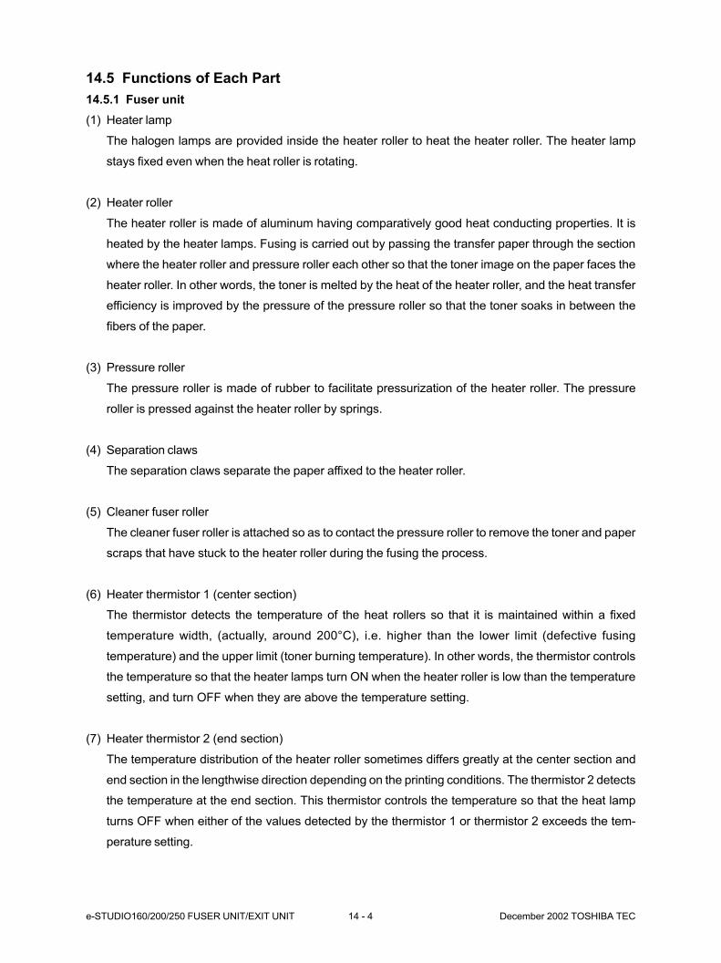
e-STUDIO160/200/250 FUSER UNIT/EXIT UNIT 14 - 4 December 2002 TOSHIBA TEC
14.5 Functions of Each Part
14.5.1 Fuser unit
(1) Heater lamp
The halogen lamps are provided inside the heater roller to heat the heater roller. The heater lamp
stays fixed even when the heat roller is rotating.
(2) Heater roller
The heater roller is made of aluminum having comparatively good heat conducting properties. It is
heated by the heater lamps. Fusing is carried out by passing the transfer paper through the section
where the heater roller and pressure roller each other so that the toner image on the paper faces the
heater roller. In other words, the toner is melted by the heat of the heater roller, and the heat transfer
efficiency is improved by the pressure of the pressure roller so that the toner soaks in between the
fibers of the paper.
(3) Pressure roller
The pressure roller is made of rubber to facilitate pressurization of the heater roller. The pressure
roller is pressed against the heater roller by springs.
(4) Separation claws
The separation claws separate the paper affixed to the heater roller.
(5) Cleaner fuser roller
The cleaner fuser roller is attached so as to contact the pressure roller to remove the toner and paper
scraps that have stuck to the heater roller during the fusing the process.
(6) Heater thermistor 1 (center section)
The thermistor detects the temperature of the heat rollers so that it is maintained within a fixed
temperature width, (actually, around 200°C), i.e. higher than the lower limit (defective fusing
temperature) and the upper limit (toner burning temperature). In other words, the thermistor controls
the temperature so that the heater lamps turn ON when the heater roller is low than the temperature
setting, and turn OFF when they are above the temperature setting.
(7) Heater thermistor 2 (end section)
The temperature distribution of the heater roller sometimes differs greatly at the center section and
end section in the lengthwise direction depending on the printing conditions. The thermistor 2 detects
the temperature at the end section. This thermistor controls the temperature so that the heat lamp
turns OFF when either of the values detected by the thermistor 1 or thermistor 2 exceeds the tem-
perature setting.

December 2002 TOSHIBA TEC 14 - 5 e-STUDIO160/200/250 FUSER UNIT/EXIT UNIT
(8) Fuser thermostat 1
The thermostat cuts the power to the heater lamps if the heater roller become abnormally hot as a
result of thermistor malfunction, for example. The thermostat on this copier is for preventing abnormal
operation. When the thermostat detects an abnormality, the thermostat must be replaced together
with the other damaged parts in the fuser.
(9) Fuser thermostat 2
Fuser thermostat 2 cuts the power to the heater lamps if fuser thermostat 1 malfunctions. When
fuser thermostat 2 detects an abnormality, it must be replaced together with any other damaged
parts.
14.5.2 Paper exit unit
(1) Exit roller
The exit roller turns as the power of the main motor or ADU motor (Upper) is transmitted to it through
the gear of the fuser, thereby transporting the paper.
(2) Pinch roller
The pinch roller helps the exit roller transport the paper. The pinch roller is pressed against the exit
roller by the spring so that it is turned by the power of the exit roller.
(3) Exit sensor
The exit sensor detects the transport of paper at the paper exit unit. A paper jam is detected accord-
ing to the on/off timing of the exit sensor.
(4) Exit guide
The exit guide is used as a guide for transporting the paper to the option ADU.
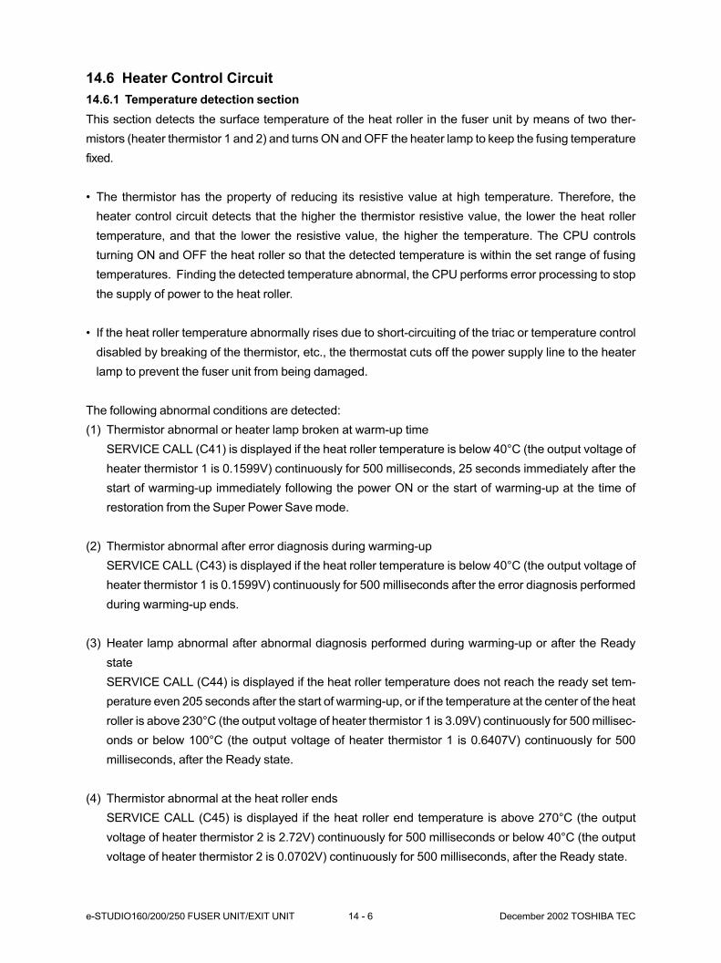
e-STUDIO160/200/250 FUSER UNIT/EXIT UNIT 14 - 6 December 2002 TOSHIBA TEC
14.6 Heater Control Circuit
14.6.1 Temperature detection section
This section detects the surface temperature of the heat roller in the fuser unit by means of two ther-
mistors (heater thermistor 1 and 2) and turns ON and OFF the heater lamp to keep the fusing temperature
fixed.
• The thermistor has the property of reducing its resistive value at high temperature. Therefore, the
heater control circuit detects that the higher the thermistor resistive value, the lower the heat roller
temperature, and that the lower the resistive value, the higher the temperature. The CPU controls
turning ON and OFF the heat roller so that the detected temperature is within the set range of fusing
temperatures. Finding the detected temperature abnormal, the CPU performs error processing to stop
the supply of power to the heat roller.
• If the heat roller temperature abnormally rises due to short-circuiting of the triac or temperature control
disabled by breaking of the thermistor, etc., the thermostat cuts off the power supply line to the heater
lamp to prevent the fuser unit from being damaged.
The following abnormal conditions are detected:
(1) Thermistor abnormal or heater lamp broken at warm-up time
SERVICE CALL (C41) is displayed if the heat roller temperature is below 40°C (the output voltage of
heater thermistor 1 is 0.1599V) continuously for 500 milliseconds, 25 seconds immediately after the
start of warming-up immediately following the power ON or the start of warming-up at the time of
restoration from the Super Power Save mode.
(2) Thermistor abnormal after error diagnosis during warming-up
SERVICE CALL (C43) is displayed if the heat roller temperature is below 40°C (the output voltage of
heater thermistor 1 is 0.1599V) continuously for 500 milliseconds after the error diagnosis performed
during warming-up ends.
(3) Heater lamp abnormal after abnormal diagnosis performed during warming-up or after the Ready
state
SERVICE CALL (C44) is displayed if the heat roller temperature does not reach the ready set tem-
perature even 205 seconds after the start of warming-up, or if the temperature at the center of the heat
roller is above 230°C (the output voltage of heater thermistor 1 is 3.09V) continuously for 500 millisec-
onds or below 100°C (the output voltage of heater thermistor 1 is 0.6407V) continuously for 500
milliseconds, after the Ready state.
(4) Thermistor abnormal at the heat roller ends
SERVICE CALL (C45) is displayed if the heat roller end temperature is above 270°C (the output
voltage of heater thermistor 2 is 2.72V) continuously for 500 milliseconds or below 40°C (the output
voltage of heater thermistor 2 is 0.0702V) continuously for 500 milliseconds, after the Ready state.

December 2002 TOSHIBA TEC 14 - 7 e-STUDIO160/200/250 FUSER UNIT/EXIT UNIT
(5) Thermistor/Heater status counter control
• To enhance the fuser unit safety, CPU works to provide the following protection:
After tow consecutive C41 errors, if a third C41 error has occurred, turning the power OFF and then
ON does not work to turn ON the heater lamp, instead immediately displaying a C41 error.
However, with the thermistor/heater status counter “1” or below, if the copier becomes ready nor-
mally, the counter is cleared to “0”.
• After service calls C41 to C45 occurred and the thermistor and heater lamp have been repaired or
replaced, if turning the power ON does not turn the heater lamp ON and an error occurs again, use
code 400 in the 08 mode to check the thermistor/heater status counter, and clear it to “0” if neces-
sary.
Heat roller surface temperature (e-STUDIO160 series): 190°C (Thermistor resistance: 5.90KΩ)
Heat roller surface temperature (e-STUDIO200/250 series): 200°C (Thermistor resistance: 5.01KΩ)

e-STUDIO160/200/250 FUSER UNIT/EXIT UNIT 14 - 8 December 2002 TOSHIBA TEC
Reference
1. The thermistor/ heater status counter never has values other than 0, 1, 2, 3, 4, 5, 6, 7, 8 and 9
written on it.
• When the power is turned ON, if the heater lamp does not turn ON and service call C41 is dis-
played immediately, check the thermistor/heater status counter. If it is “2” or over, be sure to check
the thermistor and heater lamp. Then, after repairing or replacing, it is necessary to reset the
counter to “0”(code 400 in 08 mode) and then turn the power ON.
• If the thermistor/heater status counter should show “10” or over (e.g., 11), there is a possibility that
SRAM or the data in it may have been ruined. Check the bias, high-voltage transformers and
charge wires to see if any of them is defective, and repair if necessary. Then, you have to check all
the data inside SRAM.
2. Relationship between the thermistor output voltage and heat roller temperature:
Approx. 2.33V when the temperature is 190°C, approx. 2.53V when the temperature is 200°C and
approx. 0.1599V when the temperature is 40°C.
3. Relationship between the heat roller surface temperature and the heater thermistor 1 resistance.
Fig. 14-6-1
4. Temperature control at heat roller ends
During multi copying, the temperature on the ends of the heat roller (non-paper passage areas)
generally tends to become higher than that on the paper passage areas. This temperature is de-
tected by the heater thermistor 2; i.e. when it detects a temperature of 245°C or over, the heater
lamp is set to automatically turn itself OFF, regardless of the temperature on the paper passage
areas.
16_001
Values in ( ) are for e-STUDIO200/250 series.
Temperature Thermistor resistance Fuser lamp state
190 (200) °C or below 5.9KΩ (5.01KΩ) or over ON
190 (200) °C 5.9KΩ (5.01KΩ) The previous state kept intact
190 (200) °C or over 5.9KΩ (5.01KΩ) or below OFF
Values in ( ) are for e-STUDIO200/250 series.

December 2002 TOSHIBA TEC 14 - 9 e-STUDIO160/200/250 FUSER UNIT/EXIT UNIT
14.6.2 Temperature detection by the thermistor
* The detection circuits for heater thermistors 1 and 2 are equal to each other. Here, heater thermistor 1
is described.
Fig. 14-6-2
• The input voltage is obtained by dividing the +5V among R342, Heater thermistor 1 and R337.
• The surface temperature of the heat roller varies.
• The resistance of the heater thermistor 1 changes.
• The input voltage changes.
• The input voltage is converted to digital data by the A/D converter and output to the register of the
system control GA. The CPU reads this value and detects a change in the data to judge if the heat roller
temperature is normal or abnormal.
14-06-02
+5V
R342Heater
thermistor 1
R337
SG
TH ADCDO
+5V
IC23
A/Dconverter
IC34
Systemcontrol
GA
IC66
CPU
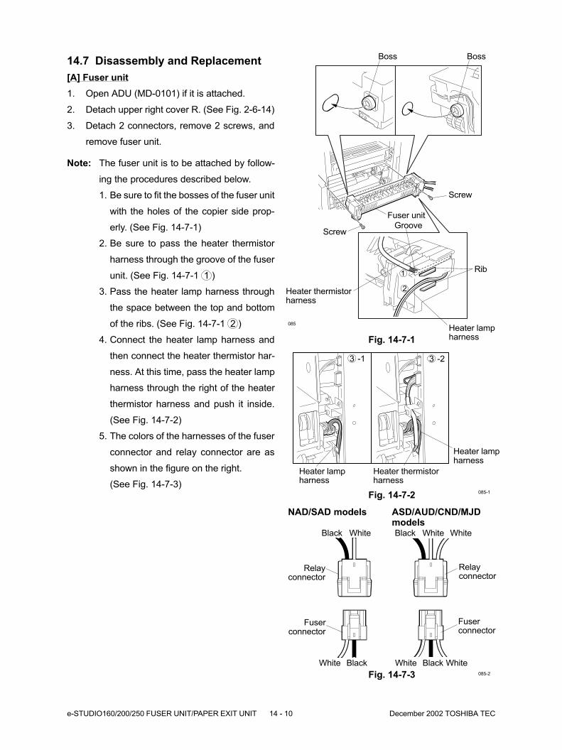
e-STUDIO160/200/250 FUSER UNIT/PAPER EXIT UNIT 14 - 10 December 2002 TOSHIBA TEC
085
Fig. 14-7-1
Boss
Fig. 14-7-2
Screw
Fuser unit
Screw
Heater lampharness
Heater thermistorharness
Heater lampharness
085-1
3 -1 3 -2
14.7 Disassembly and Replacement
[A] Fuser unit
1. Open ADU (MD-0101) if it is attached.
2. Detach upper right cover R. (See Fig. 2-6-14)
3. Detach 2 connectors, remove 2 screws, and
remove fuser unit.
Note: The fuser unit is to be attached by follow-
ing the procedures described below.
1. Be sure to fit the bosses of the fuser unit
with the holes of the copier side prop-
erly. (See Fig. 14-7-1)
2. Be sure to pass the heater thermistor
harness through the groove of the fuser
unit. (See Fig. 14-7-1 1 )
3. Pass the heater lamp harness through
the space between the top and bottom
of the ribs. (See Fig. 14-7-1 2 )
4. Connect the heater lamp harness and
then connect the heater thermistor har-
ness. At this time, pass the heater lamp
harness through the right of the heater
thermistor harness and push it inside.
(See Fig. 14-7-2)
5. The colors of the harnesses of the fuser
connector and relay connector are as
shown in the figure on the right.
(See Fig. 14-7-3)
Fig. 14-7-3 085-2
ASD/AUD/CND/MJDmodels
NAD/SAD models
Black White White
Relayconnector
Fuserconnector
White Black White
Black White
Relayconnector
Fuserconnector
White Black
Heater thermistorharness
1
2
Rib
Heater lampharness
Boss
Groove
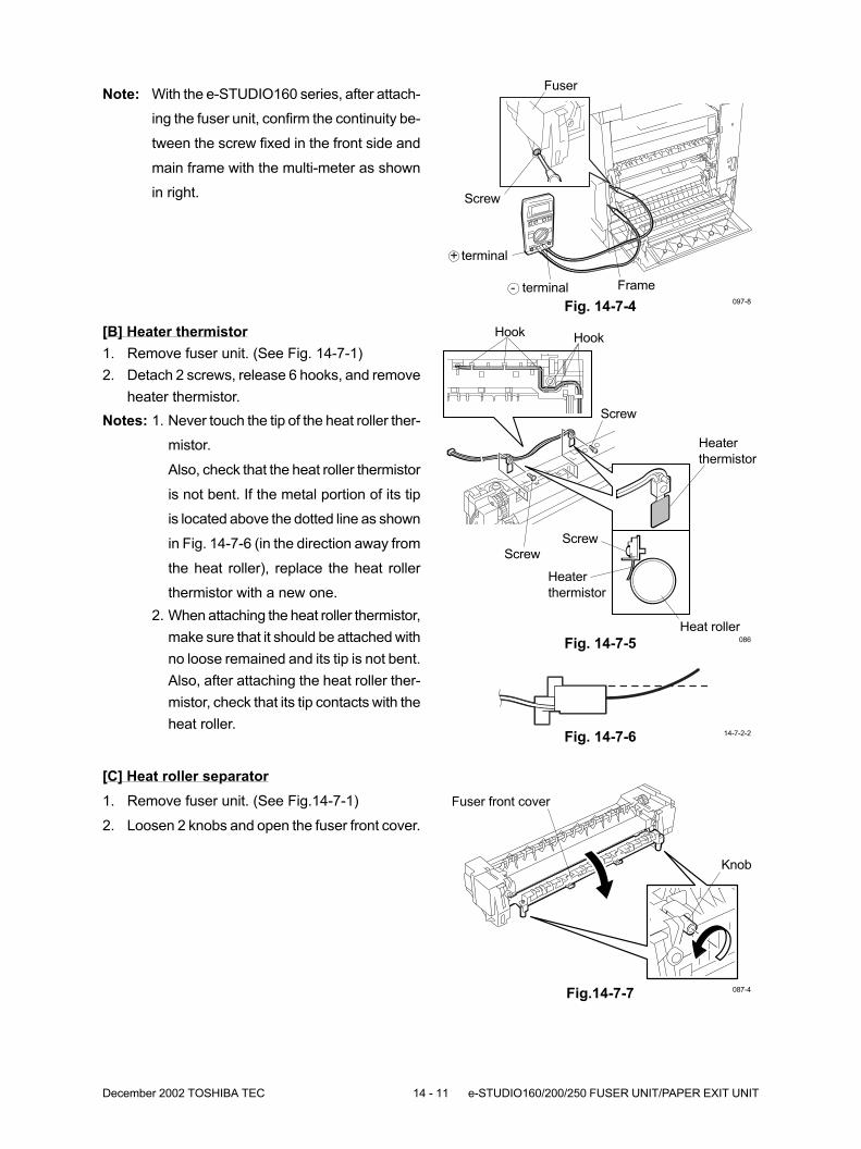
December 2002 TOSHIBA TEC 14 - 11 e-STUDIO160/200/250 FUSER UNIT/PAPER EXIT UNIT
Note: With the e-STUDIO160 series, after attach-
ing the fuser unit, confirm the continuity be-
tween the screw fixed in the front side and
main frame with the multi-meter as shown
in right. Screw
Fuser
Frame- terminal097-8
+ terminal
Fig. 14-7-4
Fig. 14-7-5
Screw
Screw
Hook
Heater
thermistor
086
Hook[B] Heater thermistor
1. Remove fuser unit. (See Fig. 14-7-1)
2. Detach 2 screws, release 6 hooks, and remove
heater thermistor.
Notes: 1. Never touch the tip of the heat roller ther-
mistor.
Also, check that the heat roller thermistor
is not bent. If the metal portion of its tip
is located above the dotted line as shown
in Fig. 14-7-6 (in the direction away from
the heat roller), replace the heat roller
thermistor with a new one.
2. When attaching the heat roller thermistor,
make sure that it should be attached with
no loose remained and its tip is not bent.
Also, after attaching the heat roller ther-
mistor, check that its tip contacts with the
heat roller.
Heater
thermistor
Heat roller
Screw
Fig. 14-7-6 14-7-2-2
[C] Heat roller separator
1. Remove fuser unit. (See Fig.14-7-1)
2. Loosen 2 knobs and open the fuser front cover.
Fig.14-7-7
Fuser front cover
Knob
087-4
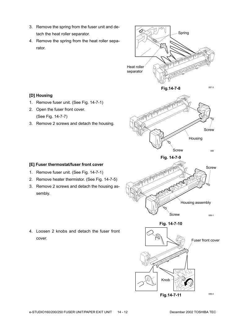
e-STUDIO160/200/250 FUSER UNIT/PAPER EXIT UNIT 14 - 12 December 2002 TOSHIBA TEC
3. Remove the spring from the fuser unit and de-
tach the heat roller separator.
4. Remove the spring from the heat roller sepa-
rator.
Fig.14-7-8 087-5
Spring
Heat roller
separator
Fig. 14-7-9
Screw
Screw
Housing
088
[D] Housing
1. Remove fuser unit. (See Fig. 14-7-1)
2. Open the fuser front cover.
(See Fig. 14-7-7)
3. Remove 2 screws and detach the housing.
Fig. 14-7-10
Screw
Housing assembly
089-1
Screw
1. Remove fuser unit. (See Fig. 14-7-1)
2. Remove heater thermistor. (See Fig. 14-7-5)
3. Remove 2 screws and detach the housing as-
sembly.
4. Loosen 2 knobs and detach the fuser front
cover.
Fig.14-7-11 089-4
Fuser front cover
Knob
[E] Fuser thermostat/fuser front cover
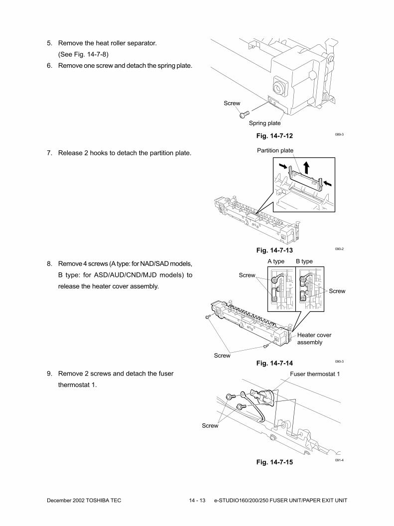
December 2002 TOSHIBA TEC 14 - 13 e-STUDIO160/200/250 FUSER UNIT/PAPER EXIT UNIT
8. Remove 4 screws (A type: for NAD/SAD models,
B type: for ASD/AUD/CND/MJD models) to
release the heater cover assembly.
Fig. 14-7-14
9. Remove 2 screws and detach the fuser
thermostat 1.
Fig. 14-7-15
Screw
Heater cover
assembly
Screw
Screw
Fuser thermostat 1
090-3
091-4
A type B type
5. Remove the heat roller separator.
(See Fig. 14-7-8)
6. Remove one screw and detach the spring plate.
Fig. 14-7-12 089-3
Screw
7. Release 2 hooks to detach the partition plate.
Fig. 14-7-13 090-2
Partition plate
Screw
Spring plate
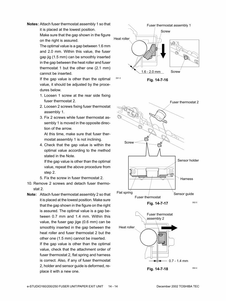
e-STUDIO160/200/250 FUSER UNIT/PAPER EXIT UNIT 14 - 14 December 2002 TOSHIBA TEC
Fig. 14-7-16091-3
Screw
Heat roller
Notes: Attach fuser thermostat assembly 1 so that
it is placed at the lowest position.
Make sure that the gap shown in the figure
on the right is assured.
The optimal value is a gap between 1.6 mm
and 2.0 mm. Within this value, the fuser
gap jig (1.5 mm) can be smoothly inserted
in the gap between the heat roller and fuser
thermostat 1 but the other one (2.1 mm)
cannot be inserted.
If the gap value is other than the optimal
value, it should be adjusted by the proce-
dures below.
1. Loosen 1 screw at the rear side fixing
fuser thermostat 2.
2. Loosen 2 screws fixing fuser thermostat
assembly 1.
3. Fix 2 screws while fuser thermostat as-
sembly 1 is moved in the opposite direc-
tion of the arrow.
At this time, make sure that fuser ther-
mostat assembly 1 is not inclining.
4. Check that the gap value is within the
optimal value according to the method
stated in the Note.
If the gap value is other than the optimal
value, repeat the above procedure from
step 2.
5. Fix the screw in fuser thermostat 2.
10. Remove 2 screws and detach fuser thermo-
stat 2.
Note: Attach fuser thermostat assembly 2 so that
it is placed at the lowest position. Make sure
that the gap shown in the figure on the right
is assured. The optimal value is a gap be-
tween 0.7 mm and 1.4 mm. Within this
value, the fuser gap jige (0.6 mm) can be
smoothly inserted in the gap between the
heat roller and fuser thermostat 2 but the
other one (1.5 mm) cannot be inserted.
If the gap value is other than the optimal
value, check that the attachment order of
fuser thermostat 2, flat spring and harness
is correct. Also, if any of fuser thermostat
2, holder and sensor guide is deformed, re-
place it with a new one.
Fig. 14-7-17 092-5
Screw
Fuser thermostat assembly 1
Fuser thermostat 2
Screw
1.6 - 2.0 mm
0.7 - 1.4 mm
Sensor holder
Harness
Sensor guideFlat spring
Fig. 14-7-18 092-4
Heat roller
Fuser thermostat
assembly 2
Fuser thermostat
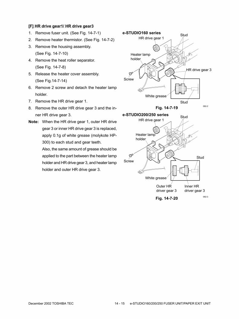
December 2002 TOSHIBA TEC 14 - 15 e-STUDIO160/200/250 FUSER UNIT/PAPER EXIT UNIT
Fig. 14-7-19092-2
HR drive gear 1
HR drive gear 3
Screw
Heater lamp
holder
Stud
Stud
White grease
[F] HR drive gear1/ HR drive gear3
1. Remove fuser unit. (See Fig. 14-7-1)
2. Remove heater thermistor. (See Fig. 14-7-2)
3. Remove the housing assembly.
(See Fig. 14-7-10)
4. Remove the heat roller separator.
(See Fig. 14-7-8)
5. Release the heater cover assembly.
(See Fig.14-7-14)
6. Remove 2 screw and detach the heater lamp
holder.
7. Remove the HR drive gear 1.
8. Remove the outer HR drive gear 3 and the in-
ner HR drive gear 3.
Note: When the HR drive gear 1, outer HR drive
gear 3 or inner HR drive gear 3 is replaced,
apply 0.1g of white grease (molykote HP-
300) to each stud and gear teeth.
Also, the same amount of grease should be
applied to the part between the heater lamp
holder and HR drive gear 3, and heater lamp
holder and outer HR drive gear 3.
e-STUDIO160 series
Fig. 14-7-20092-3
HR drive gear 1
Screw
Heater lamp
holder
Stud
Stud
White grease
e-STUDIO200/250 series
Outer HR
driver gear 3
Inner HR
driver gear 3
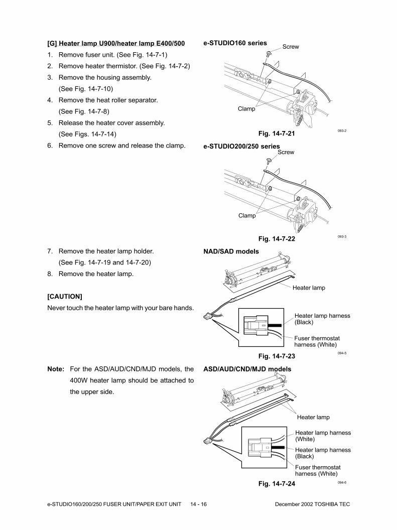
e-STUDIO160/200/250 FUSER UNIT/PAPER EXIT UNIT 14 - 16 December 2002 TOSHIBA TEC
ASD/AUD/CND/MJD models
Heater lamp
Fig. 14-7-24
Note: For the ASD/AUD/CND/MJD models, the
400W heater lamp should be attached to
the upper side.
NAD/SAD models
Heater lamp
Fig. 14-7-23
Fuser thermostatharness (White)
Heater lamp harness(Black)
Fuser thermostatharness (White)
Heater lamp harness(Black)
Heater lamp harness(White)
Fig. 14-7-22093-3
e-STUDIO200/250 seriesScrew
Clamp
Fig. 14-7-21
Screw
093-2
e-STUDIO160 series[G] Heater lamp U900/heater lamp E400/500
1. Remove fuser unit. (See Fig. 14-7-1)
2. Remove heater thermistor. (See Fig. 14-7-2)
3. Remove the housing assembly.
(See Fig. 14-7-10)
4. Remove the heat roller separator.
(See Fig. 14-7-8)
5. Release the heater cover assembly.
(See Figs. 14-7-14)
6. Remove one screw and release the clamp.
094-6
Clamp
094-5
7. Remove the heater lamp holder.
(See Fig. 14-7-19 and 14-7-20)
8. Remove the heater lamp.
[CAUTION]
Never touch the heater lamp with your bare hands.
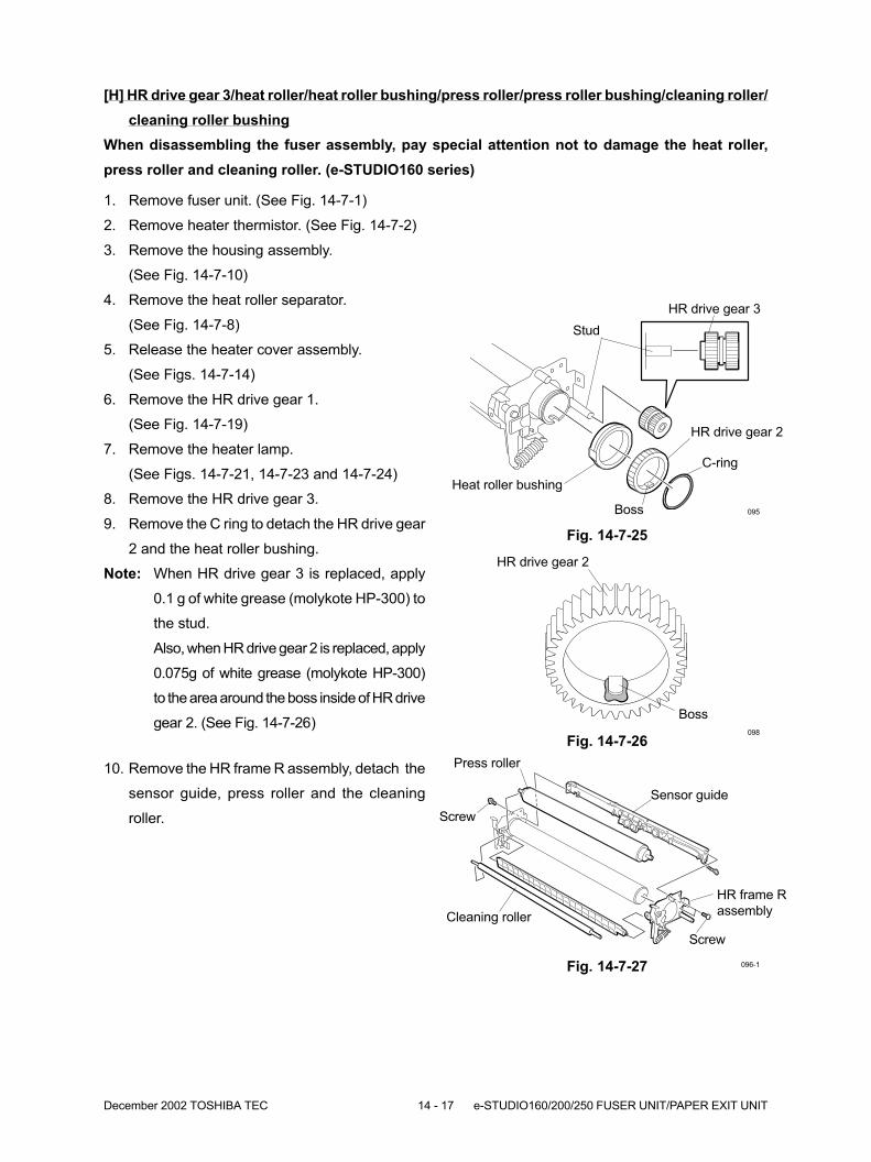
December 2002 TOSHIBA TEC 14 - 17 e-STUDIO160/200/250 FUSER UNIT/PAPER EXIT UNIT
Fig. 14-7-25
HR drive gear 3
HR drive gear 2
Heat roller bushing
C-ring
095
Stud
1. Remove fuser unit. (See Fig. 14-7-1)
2. Remove heater thermistor. (See Fig. 14-7-2)
3. Remove the housing assembly.
(See Fig. 14-7-10)
4. Remove the heat roller separator.
(See Fig. 14-7-8)
5. Release the heater cover assembly.
(See Figs. 14-7-14)
6. Remove the HR drive gear 1.
(See Fig. 14-7-19)
7. Remove the heater lamp.
(See Figs. 14-7-21, 14-7-23 and 14-7-24)
8. Remove the HR drive gear 3.
9. Remove the C ring to detach the HR drive gear
2 and the heat roller bushing.
Note: When HR drive gear 3 is replaced, apply
0.1 g of white grease (molykote HP-300) to
the stud.
Also, when HR drive gear 2 is replaced, apply
0.075g of white grease (molykote HP-300)
to the area around the boss inside of HR drive
gear 2. (See Fig. 14-7-26)
Boss
Fig. 14-7-26098
Boss
HR drive gear 2
Fig. 14-7-27
HR frame R
assemblyCleaning roller
Press roller
096-1
[H] HR drive gear 3/heat roller/heat roller bushing/press roller/press roller bushing/cleaning roller/
cleaning roller bushing
When disassembling the fuser assembly, pay special attention not to damage the heat roller,
press roller and cleaning roller. (e-STUDIO160 series)
Sensor guide
10. Remove the HR frame R assembly, detach the
sensor guide, press roller and the cleaning
roller. Screw
Screw
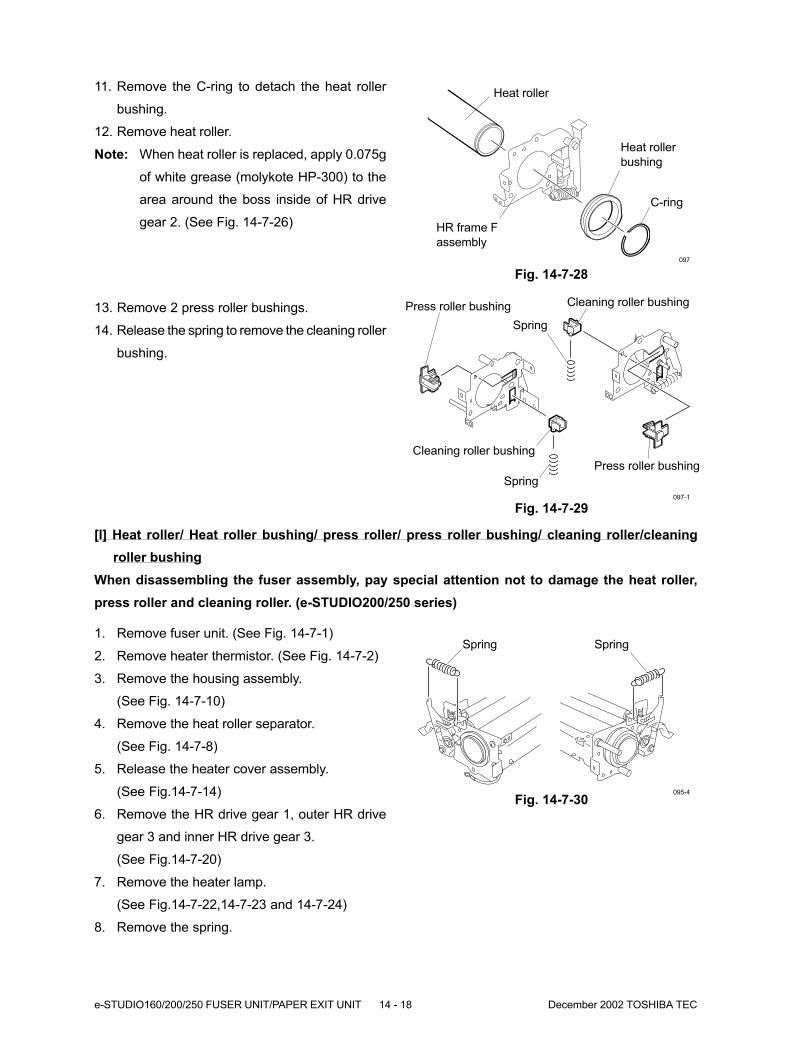
e-STUDIO160/200/250 FUSER UNIT/PAPER EXIT UNIT 14 - 18 December 2002 TOSHIBA TEC
Fig. 14-7-30095-4
Spring
[I] Heat roller/ Heat roller bushing/ press roller/ press roller bushing/ cleaning roller/cleaning
roller bushing
When disassembling the fuser assembly, pay special attention not to damage the heat roller,
press roller and cleaning roller. (e-STUDIO200/250 series)
Fig. 14-7-28
Heat roller
HR frame F
assembly
Heat roller
bushing
C-ring
097
13. Remove 2 press roller bushings.
14. Release the spring to remove the cleaning roller
bushing.
Fig. 14-7-29097-1
Press roller bushing
Press roller bushing
Spring
Cleaning roller bushing
Cleaning roller bushing
Spring
11. Remove the C-ring to detach the heat roller
bushing.
12. Remove heat roller.
Note: When heat roller is replaced, apply 0.075g
of white grease (molykote HP-300) to the
area around the boss inside of HR drive
gear 2. (See Fig. 14-7-26)
1. Remove fuser unit. (See Fig. 14-7-1)
2. Remove heater thermistor. (See Fig. 14-7-2)
3. Remove the housing assembly.
(See Fig. 14-7-10)
4. Remove the heat roller separator.
(See Fig. 14-7-8)
5. Release the heater cover assembly.
(See Fig.14-7-14)
6. Remove the HR drive gear 1, outer HR drive
gear 3 and inner HR drive gear 3.
(See Fig.14-7-20)
7. Remove the heater lamp.
(See Fig.14-7-22,14-7-23 and 14-7-24)
8. Remove the spring.
Spring

December 2002 TOSHIBA TEC 14 - 19 e-STUDIO160/200/250 FUSER UNIT/PAPER EXIT UNIT
Fig. 14-7-31 095-2
C-ring
HR drive gear 2
Heat roller bushing
9. Remove the C-ring to detach the HR drive gear
2 and the heat roller bushing.
10. Remove 2 screws, detach the arm holder, and
then remove the guide plate.
Note: When HR drive gear 2 is replaced, apply
0.075g of white grease (molykote HP-300)
to the area around the boss inside of HR
drive gear 2. (See Fig. 14-7-25)
Boss
Fig. 14-7-32 095-3
Guide plate
Arm holder
Arm holderScrew
11. Remove the C-ring to detach the heat roller
bushing.
Fig. 14-7-33
Fig. 14-7-34
097-2
097-8
Heat roller bushing
C-ring
Heat roller12. Remove heat roller.
Note: When heat roller is replaced, apply 0.075g
of white grease (molykote HP-300) to the
area around the boss inside of HR drive
gear 2. (See Fig. 14-7-25)

e-STUDIO160/200/250 FUSER UNIT/PAPER EXIT UNIT 14 - 20 December 2002 TOSHIBA TEC
16. Release the spring and detach the cleaning
roller bushing.
Fig. 14-7-37
Fig. 14-7-38
097-6
097-7
Cleaning roller
bushingSpring
Cleaning roller
bushingSpring
Fig. 14-7-35
15. Release the cleaning roller bushing and remove
the cleaning roller.
Fig. 14-7-36
097-9
097-10
E-ring
Bearing
Press roller
Bearing E-ring
Cleaning roller
13. Remove 2 screws to detach 2 washers secur-
ing the bearing.
14. Remove the press roller by removing 2 E-rings
and 2 bearings.
WasherScrew
Washer
Screw

December 2002 TOSHIBA TEC 14 - 21 e-STUDIO160/200/250 FUSER UNIT/PAPER EXIT UNIT
Harness
Clamp
Connector
Screw
Exit unit
Screw038
[J] Exit unit
1. If a Finisher (MJ-1011) is attached to the copier,
detach the finisher plate and junction block.
2. If a JSP (MJ-5001) or OCT (MJ-5002) is at-
tached to the copier, detach it.
3. If an Original Cover (KA-1600PC), ADF
(MR-2012), or the RADF (MR-3011) is attached
to the copier, open it.
4. Detach scanner cover. (See Fig. 2-6-3)
5. Detach control panel front cover.
(See Fig. 2-6-6)
6. Detach control panel bottom cover.
(See Fig. 2-6-7)
7. Detach ozone cover. (See Fig. 2-6-9)
8. Detach paper tray cover. (See Fig. 2-6-10)
9. Detach upper right cover R. (See Fig. 2-6-14)
10. Detach front frame cover F/R.
(See Fig. 2-6-18 and 2-6-19)
11. Detach exit cover. (See Fig. 2-6-20)
12. Remove one screw holding the top cover L.
(See Fig. 2-6-21)
13. Remove 2 screw holding the left cover R.
(See Fig. 2-6-21)
14. Detach inner cover. (See Fig. 2-6-21)
15. Detach the relay connector.
16. Remove 4 screws, release the clamp, and re-
move exit unit.
Note: If exit roller is found dirty, wipe off.
Fig. 14-7-39
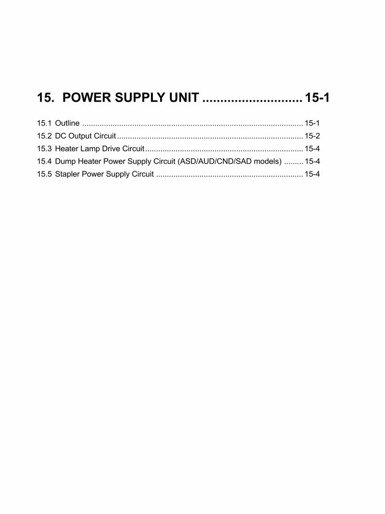
15. POWER SUPPLY UNIT ............................ 15-1
15.1 Outline ...................................................................................................... 15-1
15.2 DC Output Circuit ...................................................................................... 15-2
15.3 Heater Lamp Drive Circuit ......................................................................... 15-4
15.4 Dump Heater Power Supply Circuit (ASD/AUD/CND/SAD models) ......... 15-4
15.5 Stapler Power Supply Circuit .................................................................... 15-4

December 2002 TOSHIBA TEC 15 - 1 e-STUDIO160/200/250 POWER SUPPLY UNIT
15. POWER SUPPLY UNIT15.1 OutlineThe power supply unit provides AC and DC power for each part of this machine. The unit is made up of the
following circuits.
Fig. 15-1-115-01-02
+-
~
~
Interlock switch(Front cover)
Main switch
Interlock switch(Side cover)
FG
Noisefilter
Heater lampcontrol circuit 1
Heater lamp 1
Scannerdump heater
Fuser thermostat 1
Fuser thermostat 2
Fuser
Heater lamp 2Heater lamp
control circuit 2
Noisefilter
CN4
CN
2C
N1
24VFU2
+24V
24VFU1
DP2000/2500 series
12V
F4
F2F1
DC output circuit
Heater lamp drive circuit
20A/125V (NAD/SAD models)10A/250V (ASD/AUD/CND/MJD models)
10A/125V (NAD/SAD models)5A/250V (ASD/AUD/CND/MJD models)
4A/125V(NAD/SAD models)4A/250V(ASD/AUD/CND/MJD models)
4A/125V(NAD/SAD models)4A/250V(ASD/AUD/CND/MJD models)
Entrance
ASD/AUD/CND/SAD models
F3
PWS
-12V
5VPS
5V
HT1ON
HT2ON 11
3.3V
SG
AG
HL1
AC/I/L1
AC/I/N2
AC/O/L4
AC/O/N3
HL1
HN3
SW
/O/N
SW
/O/L
SW
/I/L
SW
/I/N
312 4
HN12
HN1
ASD/AUD/CND/MJD models
2
PG
24VSW
C/O-OU
C/O-IN 1
2 CN
5
Switchingregurator
circuit
Stapler(Option)
FUS PWA
Power supply unit
Relay PWA
CN
3
Switchingreguretor
circuit
CN
6
CN
23
7
17
20
5
12
6
4
9
3
1
2
10,13,14,15
16
8,18,19
e-STUDIO160/200/250 POWER SUPPLY UNIT 15 - 2 December 2002 TOSHIBA TEC
15.2 DC Output Circuit
This circuit converts the AC voltage input from the inlet to each DC voltage (+24V, +12V, -12V, +5V, +3.3V)
and delivers it to each part of the machine. Turning on the main switch causes the supply of all DC
voltages to begin.
Each DC voltage is supplied or cut off when the Power Save mode is activated or the following covers are
opened or closed as shown in the table below.
: Output - : Cut off
Output Protection
An overcurrent and an overvoltage protective circuit are configured for each DC voltage output. If the
output is shorted for some reason or an abnormal condition occurs in a circuit, these circuits prevent
overcurrent and overvoltage from flowing through the entire circuitry of this machine.
DC Voltage Voltage In Power Save mode Front Cover Side Cover
Value (V) (PWS signal = Low) = Open = Open
24VSW +24 - - -
24VFU2 +24 -
24VFU1 +24 -
24V +24 -
12V +12 -
-12V -12 -
5VPS +5
5V +5 -
3.3V +3.3 -

December 2002 TOSHIBA TEC 15 - 3 e-STUDIO160/200/250 POWER SUPPLY UNIT
Power supply sequence
Fig. 15-2-1
24V,24VFU1,24VFU2
200ms max. 200ms max.
+3.135V
+11.4V,-11.4V
+4.75V
+22.8V
+22.8V
+4.75V
OFF
AC input
5V
3.3V
12V,-12V
5VPS
24VSW
ON
ON:H ON:H
OFF:L
0ms min. 0ms min.
500ms max. 20ms min.
PWS signal
Close
Open
Front cover
Open
Close
Close
CloseSide cover
15-02-01
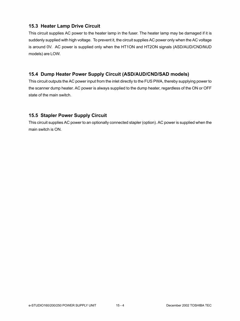
e-STUDIO160/200/250 POWER SUPPLY UNIT 15 - 4 December 2002 TOSHIBA TEC
15.3 Heater Lamp Drive Circuit
This circuit supplies AC power to the heater lamp in the fuser. The heater lamp may be damaged if it is
suddenly supplied with high voltage. To prevent it, the circuit supplies AC power only when the AC voltage
is around 0V. AC power is supplied only when the HT1ON and HT2ON signals (ASD/AUD/CND/MJD
models) are LOW.
15.4 Dump Heater Power Supply Circuit (ASD/AUD/CND/SAD models)
This circuit outputs the AC power input from the inlet directly to the FUS PWA, thereby supplying power to
the scanner dump heater. AC power is always supplied to the dump heater, regardless of the ON or OFF
state of the main switch.
15.5 Stapler Power Supply Circuit
This circuit supplies AC power to an optionally connected stapler (option). AC power is supplied when the
main switch is ON.
16. BOARD ASSEMBLY ................................ 16-1
16.1 PWA-F-MAN ............................................................................................. 16-1
16.2 PWA-F-RLY .............................................................................................. 16-2
16.3 PWA-F-PIF................................................................................................ 16-3
16.4 PWA-F-PNL .............................................................................................. 16-4
16.5 PWA-F-VR ................................................................................................ 16-4
16.6 PWA-F-SLG .............................................................................................. 16-5
16.7 PWA-F-FUS (ASD/AUD/CND/SAD models) ............................................. 16-6
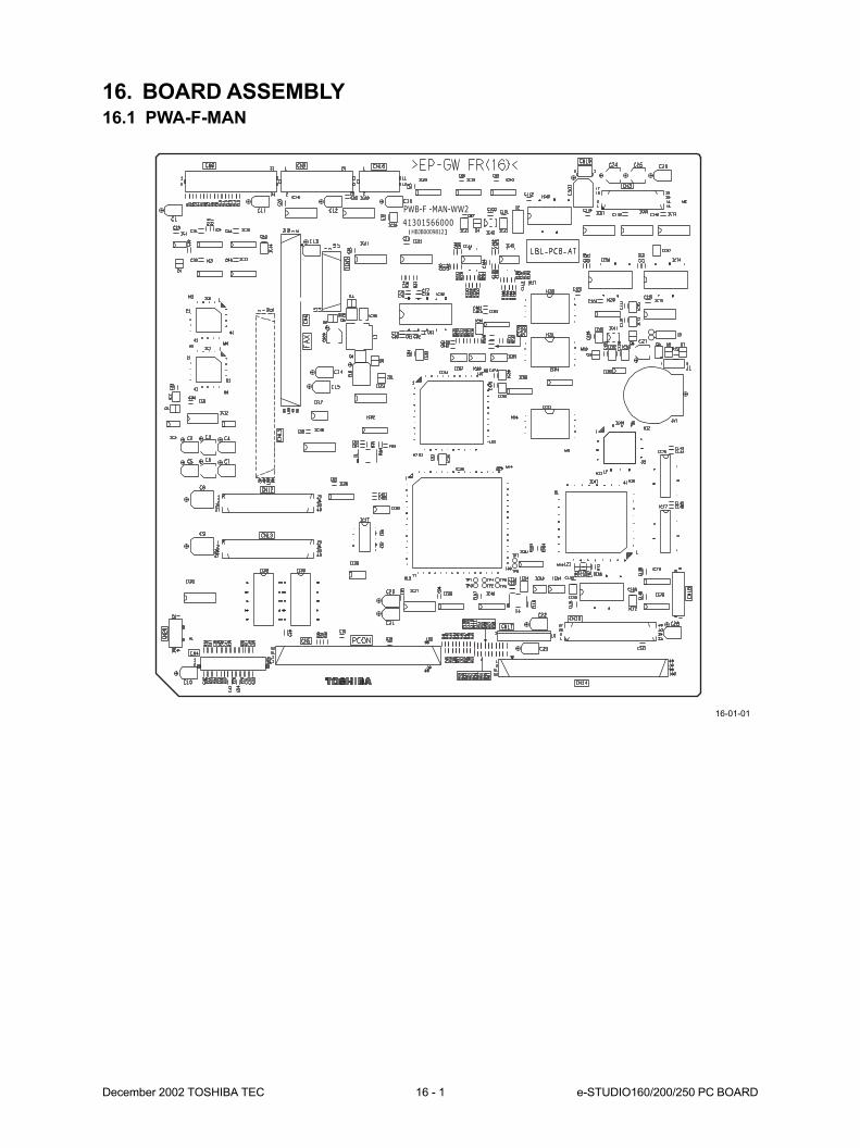
December 2002 TOSHIBA TEC 16 - 1 e-STUDIO160/200/250 PC BOARD
16. BOARD ASSEMBLY16.1 PWA-F-MAN
16-01-01
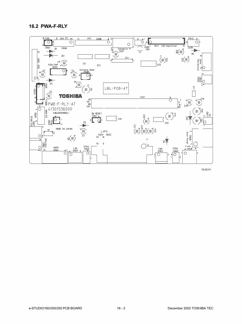
e-STUDIO160/200/250 PCB BOARD 16 - 2 December 2002 TOSHIBA TEC
16.2 PWA-F-RLY
16-02-01
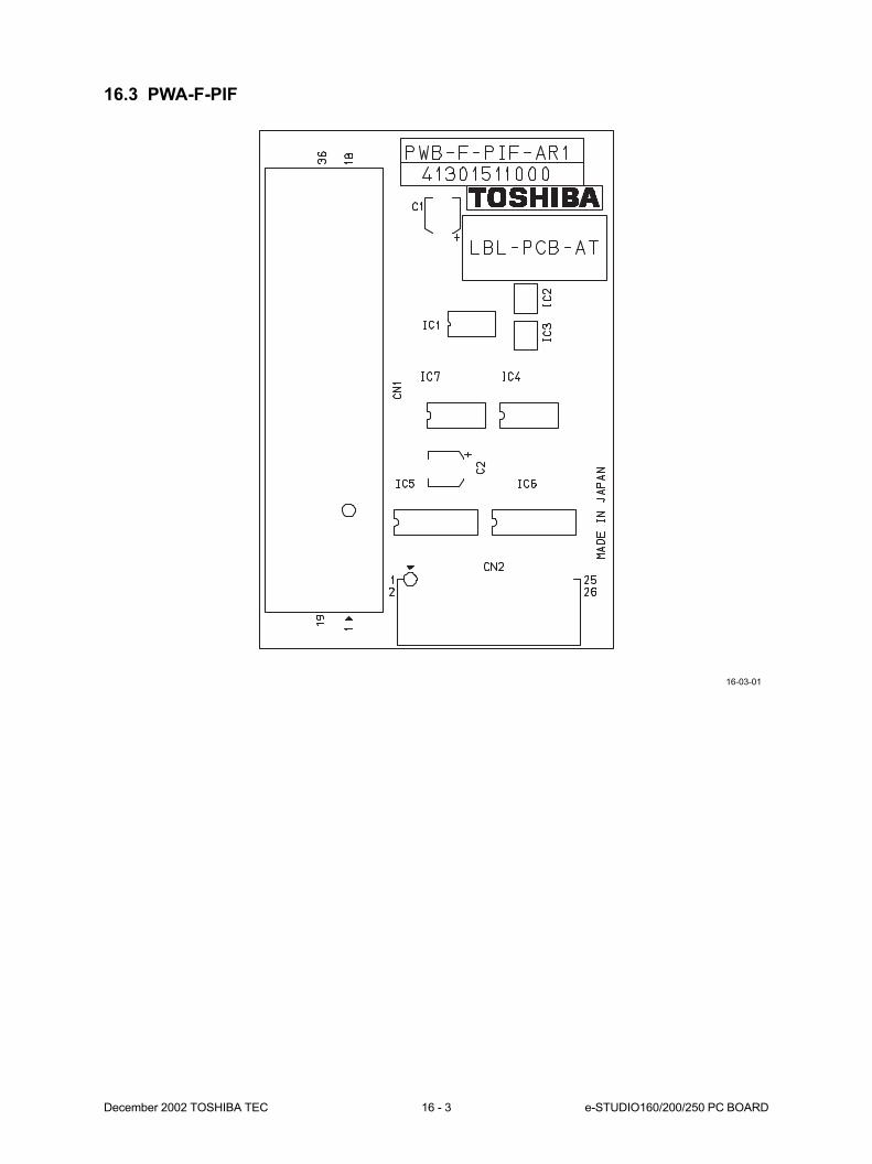
December 2002 TOSHIBA TEC 16 - 3 e-STUDIO160/200/250 PC BOARD
16.3 PWA-F-PIF
16-03-01
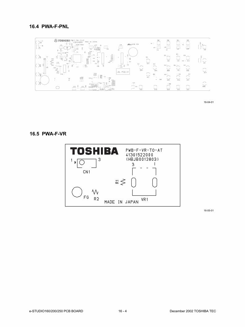
e-STUDIO160/200/250 PCB BOARD 16 - 4 December 2002 TOSHIBA TEC
16.4 PWA-F-PNL
16.5 PWA-F-VR
16-04-01
16-05-01
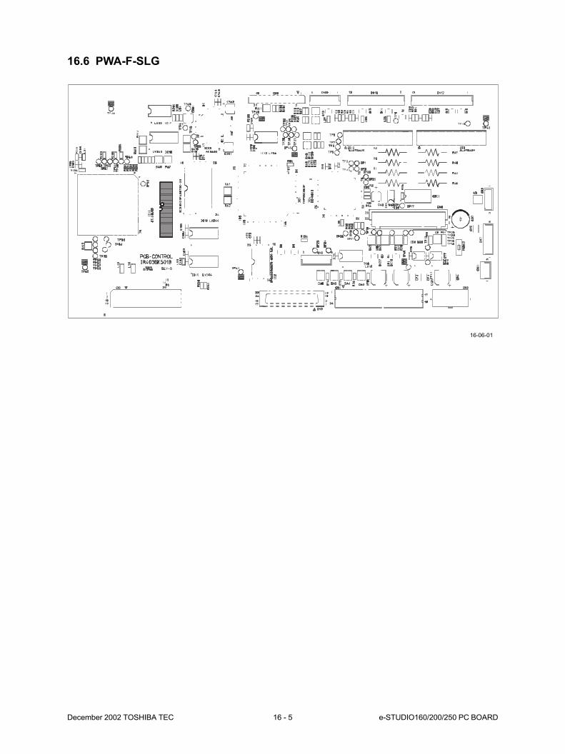
December 2002 TOSHIBA TEC 16 - 5 e-STUDIO160/200/250 PC BOARD
16.6 PWA-F-SLG
16-06-01
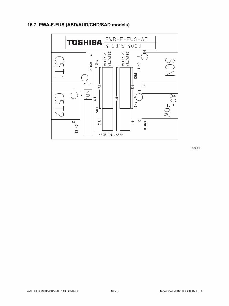
e-STUDIO160/200/250 PCB BOARD 16 - 6 December 2002 TOSHIBA TEC
16.7 PWA-F-FUS (ASD/AUD/CND/SAD models)
16-07-01

17. WIRE HARNESSCONNECTION DIAGRAMS ..................... 17-1
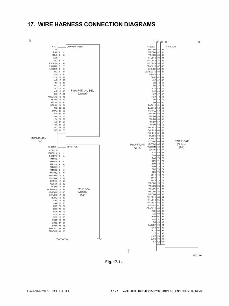
December 2002 TOSHIBA TEC 17 - 1 e-STUDIO160/200/250 WIRE HARNESS CONNECTION DIAGRAMS
17. WIRE HARNESS CONNECTION DIAGRAMS
PWA-F-MAN(1/14)
IDREQ1XINTPM1X 1
2
PM1ID0RESETX 3
4
PMI1D4PM1ID2 5
6
PM1ID8PM1ID6 7
8
PM1ID12PM1ID10 9
10
DONE1PM1ID14 11
12
IORDXIOCS4X 13
14
MDRRQ1MDM1RES 15
16
BUCSBATVCC 17
18
SA4SA2 19
20
CN6(1/2)
PWA-F-FAX(Option)
(1/2)
PM1OD6PM1OD4 31
32
PM1OD10PM1OD8 33
34
PM1OD14PM1OD12 35
36
ODREQ1OBACK1X 37
38
BUENA2WRESETX 39
40
+5VCH01 41
42
SGSG 43
44
3.3V3.3V 45
46
+12V-12V 47
48
AGAG 49
50
IDACK1XIBACK1X 51
52
PM1ID1PM1PLL 53
54
PM1ID5PM1ID3 55
56
PM1ID9PM1ID7 57
58
PM1ID13PM1ID11 59
60
IOCS9XPM1ID15 61
62
INTMD1IOWRX 63
64
FAXX33MMDTRQ1 65
66
SA1BUCHG 67
68
SA5SA3 69
70
SD3SD1 71
72
SD7SD5 73
74
SD11SD9 75
76
SD15SD13 77
78
PM1OD3PM1OD1 79
80
PM1OD7PM1OD5 81
82
PM1OD11PM1OD9 83
84
PM1OD15PM1OD13 85
86
ODACK1XLSYNC1 87
88
TX1RX1 89
90
+5VCH02 91
92
FAXDETSG 93
94
3.3V3.3VB 95
96
+12V-12V 97
98
BV5VPS 99
100
CN6(2/2)
313233343536373839404142434445464748495051525354555657585960616263646566676869707172737475767778798081828384858687888990919293949596979899100
CN101(2/2)
PWA-F-FAX(Option)
(2/2)PWA-F-MAN
(2/14)
RX1TX1 1
2
LD1CML1 3
4
ATT3DB1NC 5
6
RLADJ21RLADJ11 7
8
SGNC 9
10
AG-12V 11
12
NC+12V 13
14
AGNC 15
16
ANSDET0CI1 17
18
REVB1REVA1 19
20
NCHOOK1 21
22
SG5VPS 23
24
-12V+5V 25
26
+12VAG 27
28
NCNC 29
30
CN3
PWA-F-NCU-US/EU(Option)
SD2SD0 21
22
SD6SD4 23
24
SD10SD8 25
26
SD14SD12 27
28
PM1OD2PM1OD0
CN101(1/2)
2930
123456789101112131415161718192021222324252627282930
CN9(US)/CN4(EU)
23456789101112131415161718192021222324252627282930
1
Fig. 17-1-1
17-01-01

e-STUDIO160/200/250 WIRE HARNESS CONNECTION DIAGRAMS 17 - 2 December 2002 TOSHIBA TEC
PWA-F-MAN(3/14)
PCFWENAPOEX 1
2
2WNININATFD 3
4
PEERRNACK 5
6
PCIFD6NFAULT 7
8
PCIFD2PCIFD4 9
10
CRDYXPCIFD0 11
12
ERRORPEADYX 13
14
COMREQPCLVSP 15
16
DPOA13DPOA15 17
18
DPOA9DPOA11 19
20
DPOA5DPOA7 21
22
DPOA1DPOA3 23
24
DPOD13DPOD15 25
26
DPOD9DPOD11 27
28
DPOD5DPOD7 29
30
PCDIRPOEX 1
2
PCIFD0PCFWENA 3
4
PCIFD2PCIFD1 5
6
PCIFD4PCIFD3 7
8
PCIFD6PCIFD5 9
10
PCDETPCIFD7 11
12
NATFDNSTROB 13
14
2WNINININIT 15
16
NACKNSELIN 17
18
PEERRBUSY 19
20
NFAULTSELECT 21
22
5VPS5VPS 23
24
SGSG 25
26
CN4 CN2
CN5(1/2)
PWA-F-PCL(Option)
(1/2)
PWA-F-PIF PC
123456789
1011121314151617181920212223242526
DATA1nStrobe
DATA3DATA2
DATA5DATA4
DATA7DATA6
nACKDATA8
PErrorBusy
nAutoFdSelect
SGNC
LogicFG
SGSG
SGSG
SGSG
SGSG
CN1
123456789
1011121314151617181920212223242526
SGSG
SGSG
nFaultnInit
NCNC
nSelectInNC
27282930313233343536
DPOD1DPOD3 31
32
NCDPORESX 33
34
RBDINXWAIT 35
36
+5VG/PSEL 37
38
5VPS+5V 39
40
SG5VPS 41
42
SGPCDET 43
44
SGSG 45
46
SGSG 47
48
SGSG 49
50
SELECT 56
PCIFD5PCIFD7 57
58
PCIFD1PCIFD3 59
60
TXDPCLPOWER 61
62
PCLVDRXDPCL 63
64
DPOA16DOTCLK 65
66
DPOA12DPOA14 67
68
DPOA8DPOA10 69
70
DPOA4DPOA6 71
72
DPOA0DPOA2 73
74
DPOD12DPOD14 75
76
DPOD8DPOD10 77
78
DPOD4DPOD6 79
80
DPOD0DPOD2 81
82
DPORWXCSP1X 83
84
PCLSETINTPRX 85
86
+5VG/PCHK 87
88
5VPS+5V 89
90
SG5VPS 91
92
SGSG 93
94
SGSG 95
96
SGSG 97
98
SGSG 99
100
CN5(2/2)
PWA-F-PCL(Option)
(2/2)
NSTROBPCDIR 51
52
NSELINNINIT 53
54BUSY 55
PWA-F-MAN(4/14)
Fig. 17-1-2
17-01-02
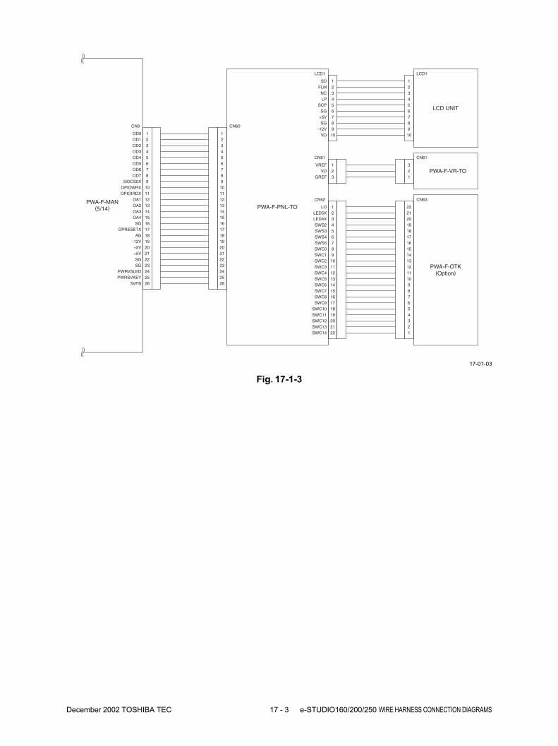
December 2002 TOSHIBA TEC 17 - 3 e-STUDIO160/200/250 WIRE HARNESS CONNECTION DIAGRAMS
PWA-F-MAN(5/14) PWA-F-PNL-TO
LCD UNIT
OD1OD0 1
2
OD3OD2 3
4
OD5OD4 5
6
OD7OD6 7
8
OPIOWRX5IOCS0X 9
10
OA1OPIOIRDX 11
12
OA3OA2 13
14
SGOA4 15
16
AGOPRESETX 17
18
+5V-12V 19
20
SG+5V 21
22
PWRVSLEDSG 23
24
5VPSPWRSVKEY 25
26
CN9 CN60
1234567891011121314151617181920212223242526
FLMSD
LPNC
SGSCP
SG+5V
VO-12V
LCD1 LCD1
12345678910
12345678910
PWA-F-VR-TOVOVREF
GREF
CN61
123
CN61
321
PWA-F-OTK(Option)
LED5XLO
SWS2LED4X
SWS4SWS3
SWC0SWS5
SWC2SWC1
SWC4SWC3
SWC6SWC5
SWC8SWC7
SWC10SWC9
SWC12SWC11
SWC14SWC13
CN62
12345678910111213141516171819202122
CN63
2120191817161514131211109
22
87654321
Fig. 17-1-3
17-01-03

e-STUDIO160/200/250 WIRE HARNESS CONNECTION DIAGRAMS 17 - 4 December 2002 TOSHIBA TEC
PIXA2PIXA0 1
2
PIXA6PIXA4 3
4
PIXA10PIXA8 5
6
CS2XBPIXA12 7
8
PSDRASXRPBA1 9
10
SDCLK1PSDDQMUR 11
12
PIXD2PIXD0 13
14
PIXD6PIXD4 15
16
PIXD10PIXD8 17
18
PIXD14PIXD12 19
20
3.3VSDRM1ID 21
22
SG3.3V 23
24
PIXA1SG 25
26
PIXA5PIXA3 27
28
PIXA9PIXA7 29
30
CS1XBPIXA11 31
32
PSDWERPBA0 33
34
PSDDQMLRPSDCASXR 35
36
PIXD1PSDCKER 37
38
PIXD5PIXD3 39
40
PIXD9PIXD7 41
42
PIXD13PIXD11 43
44
3.3VPIXD15 45
46
SG3.3V 47
48
MEM1DETSG 49
50
CN12
PWA-F-MAN(6/14)
PWA-F-MEM1
(Option)
PIXA2PIXA0 1
2
PIXA6PIXA4 3
4
PIXA10PIXA8 5
6
CS4XBPIXA12 7
8
PSDRASXRPBA1 9
10
SDCLK2PSDDQMUR 11
12
PIXD2PIXD0 13
14
PIXD6PIXD4 15
16
PIXD10PIXD8 17
18
PIXD14PIXD12 19
20
3.3VSDRM2ID 21
22
SG3.3V 23
24
PIXA1SG 25
26
PIXA5PIXA3 27
28
PIXA9PIXA7 29
30
CS3XBPIXA11 31
32
PSDWERPBA0 33
34
PSDDQMLRPSDCASXR 35
36
PIXD1PSDCKER 37
38
PIXD5PIXD3 39
40
PIXD9PIXD7 41
42
PIXD13PIXD11 43
44
3.3VPIXD15 45
46
SG3.3V 47
48
MEM2DETSG 49
50
CN13
PWA-F-MAN(7/14)
PWA-F-MEM2
(Option)
123456789
1011121314151617181920212223242526272829303132333435363738394041424344454647484950
CN106
123456789
1011121314151617181920212223242526272829303132333435363738394041424344454647484950
CN106
Fig. 17-1-4
17-01-04

December 2002 TOSHIBA TEC 17 - 5 e-STUDIO160/200/250 WIRE HARNESS CONNECTION DIAGRAMS
CN14(1/2)
PWA-F-MAN-AU1 / PWA-F-RLY-AU1
(Option)(1/2)
PWA-F-MAN(8/14)
SG 1
5VPSSG 2
3
5VPS5VPS 4
5
+5V+5V 6
7
SG+5V 8
9SG 10
PCIFD1PCIFD3 21
22
PEERRNFAULT 23
24
AU1INITNACK 25
26
PCDIRNATFD 27
28
DPOD13DPOD15 29
30
DPOD9DPOD11 31
32
DPOD5DPOD7 33
34
DPOD1DPOD3 35
36
DPOA14DPOA16 37
38
DPOA10DPOA12 39
40
DPOA6DPOA8 41
42
DPOA2DPOA4 43
44
CSP1XDPOA0 45
46
INTPRXDPORWX 47
48
SGSG 49
50
SGSG 51
52
IOCS3X5IOWRX 53
54
D12D14 55
56
D8D10 57
58
D4D6 59
60
D0D2 61
62
A6A8 63
64
A2A4 65
66
PSVENAAU1SET 67
68
PCIFD4PCIFD6 69
70
PCIFD0PCIFD2 71
72
BUSYSELECT 73
74
NINITNSELIN 75
76
OPOEXNSTROB 77
78
DPOD12DPOD14 79
80
DPOD8DPOD10 81
82
DPOD4DPOD6 83
84
DPOD0DPOD2 85
86
DPOA13DPOA15 87
88
DPOA9DPOA11 89
90
DPOA5DPOA7 91
92
DPOA1DPOA3 93
94
OEPXDPORESX 95
96
RBDINXWAIT 97
98
SGSG 99
100
CN14(2/2)
CN17
PWA-F-MAN-AU1 /PWA-F-RLY-AU1
(Option)(2/2)
PWA-F-MAN(9/14)
SGSG 1
2
5IORDXSG 3
4
D13D15 5
6
D9D11 7
8
D5D7 9
10
D1D3 11
12
A7A9 13
14
A3A5 15
16
AU1INTA1 17
18
PCIFD5PCIFD7 19
202122232425262728293031323334353637383940414243444546474849505152535455565758596061626364656667686970
123456789
1011121314151617181920
12345678910
7172737475767778798081828384858687888990919293949596979899100
Fig. 17-1-5
17-01-05
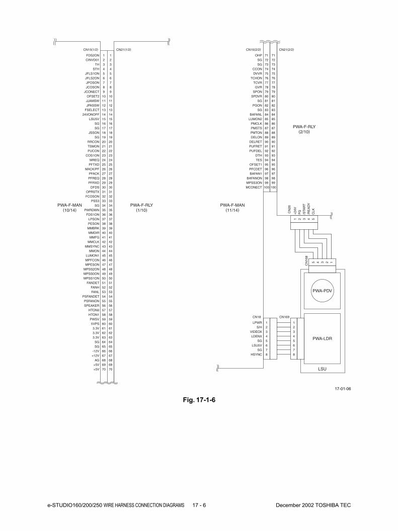
e-STUDIO160/200/250 WIRE HARNESS CONNECTION DIAGRAMS 17 - 6 December 2002 TOSHIBA TEC
CN15(1/2)
PWA-F-RLY(1/10)
PWA-F-MAN(10/14)
PUCONTSMON 21
22
MREQCOS1ON 23
24
MACK/PFPFTXD 25
26
PFREQPFACK 27
28
DFDSPFRXD 29
30
FCOSONOPRSTX 31
32
SGPSS3 33
34
FDS1ONPWRDWN 35
36
PESONLPSON 37
38
MMDIRMMBRK 39
40
MMCLKMMFG 41
42
MMONMMSYNC 43
44
MPFCONLUMON1 45
46
MPSS2ONMPESON 47
48
MPSS1ONMPSS0ON 49
50
3132333435363738394041424344454647484950
CN15(2/2) CN21(2/2)
PWA-F-RLY(2/10)
PWA-F-MAN(11/14)
CINVD01FDS2ON 1
2
STHTH 3
4
JFLS2ONJFLS1ON 5
6
JCOSONJPOSON 7
8
OFSET2JCONECT 9
10
JPASSWJJAMSW 11
12
24VONOFFFSELECT 13
14
SGLSU5V 15
16
JSSONSG 17
18
RRCONSG
CN21(1/2)
19
12345678910111213141516171819
2021222324252627282930
20
FANHFANDET 51
52
PSFANDETFANL 53
54
SPEAKERPSFANON 55
5152535455
56
HTON1HTON0 57
58
5VPSPWSV 59
60
5657585960
S/HLPWR 1
2
LDENXVIDEOX 3
4
LSU5VSG 5
6
HSYNCSG 7
8
CN18 CN169
PWA-LDR
LSU
PWA-PDV
PG
+24
V
/RE
AD
Y/S
TAR
T
CLK
1 2 3 4 5
CN
26
CN
168
SGOHP 71
72
CCONSG 73
74
TCHONDVVR 75
76
GVRTCVR 77
78
SPDVRSPON 79
80
PGONSG 81
82
BAFANLSG 83
84
PMCLKLUMON2 85
86
PMTONPMSTS 87
88
DELRETDELON 89
90
PUFDELPUFRET 91
92
TESDTH 93
94
PFCDETOFSET1 95
96
BAFANONBAFAN1 97
98
MCONECTMPSS3ON 99
100
7172737475767778798081828384858687888990919293949596979899
100
3.3V3.3V 61
62
SG3.3V 63
64
-12VSG 65
66
AG+12V 67
68+5V 69+5V 70
61626364656667686970
5 4 3 2 1
12345678
Fig. 17-1-6
17-01-06

December 2002 TOSHIBA TEC 17 - 7 e-STUDIO160/200/250 WIRE HARNESS CONNECTION DIAGRAMS
CN8
PWA-F-SLG(1/2)
PWA-F-MAN(12/14)
PWA-F-RLY(3/10)
24VF1 1
PG24VF1 2
3PG 4
1234
CN49 CN5
+5V 1
HPSENSG 2
3
321
321
+5V 4SG 5
PLSEN 6
CN8
SC/REQHT/ACK 21
22
APDS1NC 23
24
5VPSCOVER1 25
26
3.3V+5V 27
28
SG3.3V 29
30
SGSG 31
32
AG+12V 33
34
SIDTA1SIDTA0 1
2
SIDTA3SIDTA2 3
4
SIDTA5SIDTA4 5
6
SIDTA7SIDTA6 7
8
SHDENSCDCLK 9
10
RXDSVDEN 11
12
HT/REQTXD 13
14
DTRSC/ACK 15
16
SCNRSTDEN 17
18
SGPHSYC
CN4
1920
2122232425262728293031323334
1234567891011121314151617181920
HOME-SEN
PWA-F-CCD
ORCOV-SEN
SA 1
S/A+24V 2
3SB 4
+24V 5S/B 6
CN7123456789
1011
SCN-MOT
CN9
+12V+12V 1
2
OS1SGND 3
4
OS2SGND 5
6
CCDCPSGND 7
8
CCDRSSGND 9
10
CK1ASGND 11
12
CK2BSGND 13
14
CK2ASGND 15
16
CCDSHSGND 17
18
+5V+5V 19
20
10987654321
20191817161514131211
CN1
1124122313221421152016191718
1342333324315306297288279261025
1124122313221421152016191718
1342333324315306297288279261025
Fig. 17-1-7 17-01-21
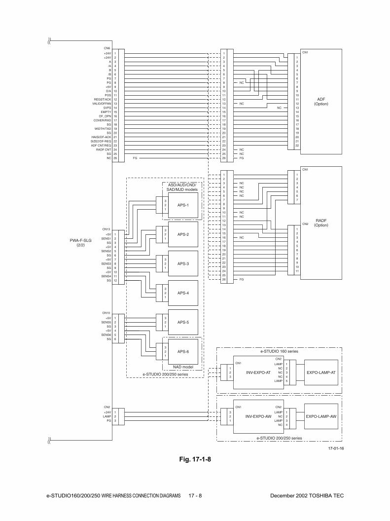
e-STUDIO160/200/250 WIRE HARNESS CONNECTION DIAGRAMS 17 - 8 December 2002 TOSHIBA TEC
PWA-F-SLG(2/2)
+5V 1
SGSENS5 2
3
321
321
+5V 4SENS6 5
SG 6
CN10
CN6
SIZE2/DF-REQHAISI/DF-ACK 21
22
RADF CNTADF CNT/REQ 23
24
NC FGSG 25
26
+24V+24V 1
2
/AA 3
4
/BB 5
6
PGPG 7
8
D/A+5V 9
10
REGST/ACKPOS 11
12
5VPSVALID/DFFAN 13
14
DF_OPNEMPTY 15
16
SGCOVER/RXD 17
18
SGWIDTH/TXD 19
20
ADF(Option)
2122
123456789
101112131415161718192021
2223242526
123456789
1011121314151617181920
NCNCNCNC
NCNC
NC
FG
CN1
RADF(Option)
212223242526
123456789
1011121314151617181920
1011
1234567
123456789
CN1
CN2
INV-EXPO-AT
INV-EXPO-AW
EXPO-LAMP-AT
EXPO-LAMP-AW
CN2
LAMP+24V 1
2PG 3
123
12345
NCLAMP
NCNC
LAMP
321
1234
LAMPNC
LAMPNC
+5V 7
SGSENS3 8
9
321
321
+5V 10SENS4 11
SG 12
+5V 1
SGSENS1 2
3+5V 4
SENS2 5SG 6
CN13
APS-3
APS-4
APS-5
APS-6
321
APS-2
321
APS-1
ASD/AUD/CND/SAD/MJD models
NAD model
e-STUDIO 200/250 series
e-STUDIO 160 series
e-STUDIO 200/250 series
CN1CN2
CN1 CN2
FG
NCNC
NC
NCNC
Fig. 17-1-8
17-01-16

December 2002 TOSHIBA TEC 17 - 9 e-STUDIO160/200/250 WIRE HARNESS CONNECTION DIAGRAMS
PS-LVPS-US/EU-AT/AW
MAIN-SWCN4 CN120
SW /I/LSW /I/N 1
2
SW /O/LSW /O/N 3
4
SIIL-SW FRIL-SWCN5
C/O-OUC/O-IN 1
2
HL
CN3 CN122
CN175
1
NCHN1 2
3
U900-HL
FUS-THM
HEA1-THM
HEA2-THM
E400-HL
ASD/AUD/CND/MJD models
NAD/SAD models
CHK
CN44
1+5V
ATH123
+5V 4
THCHKATH2 5
6
E500-HL
Fuser
PWA-F-FUS
CN2Entrance
AC /I/NAC /I/L 1
2
AC /O/LAC /O/N 3
4
282727
FG
1234
STP(Option)
CN1
HN
HL 1
3NC 2
12
123
SCN-DH-100/115/23012
SCN-THM1234
123
12
CN23
3.3VHT1ON 1
2
5VPS+5V 3
4
-12V+12V 5
6
PG+24V 7
8
PGVM 9
10
PWSHT2ON 11
12
SGSG 13
14
AGSG 15
16
PG24VF1 17
18
CN6
123456789
101112131415161718
24VF2PG 19
201920
ASD/AUD/CND/SAD models
PWA-F-RLY(4/10)
CN113
Not used
Not used
CN112CN110
CN111
LNC
N
LNC
N
NL
L
N
21
1324
321
HL
CN3 CN122
1
HN2HN1 2
3
FUS-THM321
321
654
456
123
3.3VHT1ON
5VPS5V
-12V12V
PG24V
PG24VSW
PWSHT2ON
SGSG
AGSG
PG24VFU2
24VFU1PG
Fig. 17-1-9
17-01-17
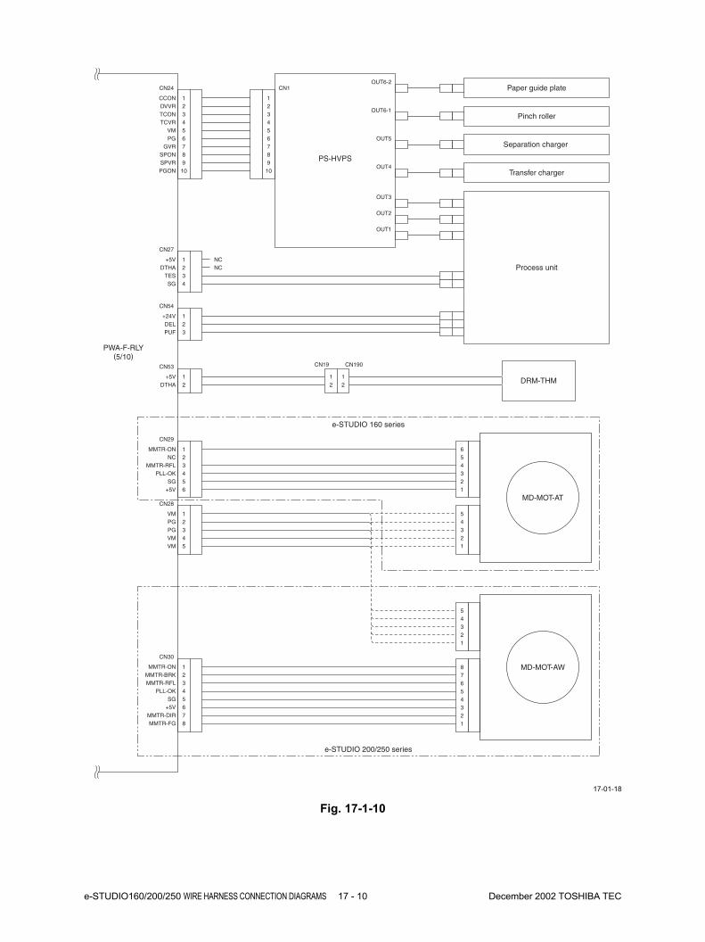
e-STUDIO160/200/250 WIRE HARNESS CONNECTION DIAGRAMS 17 - 10 December 2002 TOSHIBA TEC
Separation charger
PS-HVPS
Process unit
PWA-F-RLY(5/10)
CN24
DVVRCCON 1
2
TCVRTCON 3
4
PGVM 5
6
SPONGVR 7
8SPVR 9
10PGON
CN27
DTHA+5V 1
2
SGTES 3
4
+24V
CN54
1DEL 2
3PUF
34
Transfer charger
Paper guide plate
Pinch roller
MMTR-ON
CN30
1MMTR-BRKMMTR-RFL
23
PLL-OK 4
+5VSG 5
6
MMTR-FGMMTR-DIR 7
8
1
1
1
1
OUT2
OUT3
OUT4
OUT5
OUT6-1
OUT6-2
1
1
1
1
1
1
1
1
1
1
1
OUT11
1
1
1
MD-MOT-AT
e-STUDIO 160 series
e-STUDIO 200/250 series
MMTR-ON
CN29
1NC
MMTR-RFL23
PLL-OK 4
+5VSG 5
6
MD-MOT-AW
VM
CN28
1PGPG
23
VM 4VM 5
CN1
123456789
10
54321
654321
87654321
54321
NCNC
CN53 CN19 CN190
DTHA+5V 1
2DRM-THM
12
12
Fig. 17-1-10
17-01-18
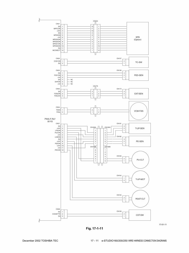
December 2002 TOSHIBA TEC 17 - 11 e-STUDIO160/200/250 WIRE HARNESS CONNECTION DIAGRAMS
SFB(Option)
PWA-F-RLY(6/10)
CN31
CN304
MPFCONSG 1
2
SG+24V 3
4
+5VMPESON 5
6
MPSS2ONMPSS3ON 7
8MPSS1ON 9
10MPSS0ONSG 11
12
121110987654321MCONECT
CN32 CN157
SGCOS1ON
TC-SW
SG
CN33
1FDS1ON 2
3+5VFED-SEN
CN156
SG 4DHPON 5
6+5V
CN45
CN179
CN173
FDS2ONSG 1
23
EXT-SENFDSLED
CN34
FANLFANH 1
2VCM-FAN
123456789
101112
21
12
321
123
321
321
21
12
NCNCNC
CN37
+24VSG 1
2
PUCONLPSON 3
4
LUMON+5V 5
6
+24VSG 7
8PESON 9
10+24V+5V 11
12PRCON
CN183
CN180B
CN180A
CN180B
CN180A
PU-CLT
T-UP-SEN
CN181
CST-SW
PE-SEN
CN182
CN164
T-UP-MOT
CN155
CN159
RGST-CLT
CN38
CASSETTENC 1
2SG 3
7654321
123
321
321
4567
21
12
21
12
12
3456
56
4321
Fig. 17-1-11
17-01-11
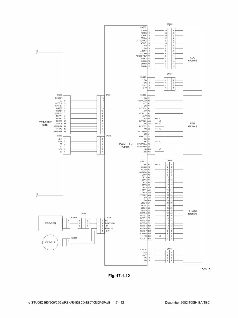
e-STUDIO160/200/250 WIRE HARNESS CONNECTION DIAGRAMS 17 - 12 December 2002 TOSHIBA TEC
PWA-F-PFC(Option)
CN36
SGPFCDET 1
2
PFCRST24VCHK 3
4
RGTSTRSTPR 5
6
PSTP/1EXIT/SW 7
8PFRXD 9
10PFREQ
123456789
10PFACK 11
12MACK/PFPFTXD 13
14MREQ/PF
1112
CN35
+24V+24V 1
2
PGPG 3
4
SG+5V 5
6
123456
CN201
CN202
1
1413121110987654321
654321
CN203
FDM-BFDM-D 1
2
FDM-AFDM-C 3
4
ADUFLCRT-DOWNA 5
6
SG+5V 7
8ADCNT 9
10ADUFU
123456789
10ADUCOVSW 11
12EXM-AEXM-C 13
15EXM-D14EXM-B
1112
CN323
123456789
10111213
1514
1514131211109876543
12
CN204
SGSG 1
2
+24V+24V 3
4
1234
CN324
4321
1234
CN207
+24V+24V 1
2
PGPG 3
4
1234
CN501
1234
1234
ADU(Option)
CN208
PFUPEMPSG A1
A2
SG+5V A3
A4
+5VPFUTUP A5
A6
+24VPFUPCLT A7
A8+5V A9
A10SIZPFU1
123456789
10SG A11
B1PFUCNTNC B2
B4SGB3SIZUPFU0
1112
B5PFUCOVSG B6
B7NCPFUTRM-A B8
B10NCB11SG
B9PFUTRM-B
CN205
PFUFD-SWSG1
2
PFUFDCLT+5V3
4
1234
321
123
+24V5
CN206
CLK-CNC A1
A2
SCSW-CCLK-B A3
A4
DRV6DRV7 A5
A6
DRV4DRV5 A7
A8DRV3 A9
A10DRV2
123456789
10DRV1 A11
B1SIZE-0SIZE-1 B2
B4SIZE-3B3SIZE-2
A12DRV0PFPRST A13
A15SGA14+5V
B12RETS-7SCSW-B B13
B15LCFCNTB14NC
1112
B5RETS-0RETS-1 B6
B7RETS-2RETS-3 B8
B10RETS-5B11RETS-6
B9RETS-4OCF-SEN
CN154
CN165
321
CN163
OCF-CLT21
PFU(Option)
PFP/LCF(Option)
CN500
13579
1113151719212325
2927
3028262422201816
1214
108642
13579
1113151719212325
2927
3028262422201816
1214
108642
PWA-F-RLY(7/10)
NCNCNC
NC
NC
NC
NC
NC
Fig. 17-1-12
17-01-12

December 2002 TOSHIBA TEC 17 - 13 e-STUDIO160/200/250 WIRE HARNESS CONNECTION DIAGRAMS
PWA-F-RLY(8/10) Speaker
CN170
CN172
CN47
SP-SP+ 1
2
FRCOV-SW
CN52
FCOSONSG 1
2
CN50
FANLFANH
FANLFANH
1234
POW-FAN
PU-FAN
12
12
21
JSP / OCT/ Bridge cover
(Option)
CN41
OFFSET1OFFSET2 1
2
+24VPG 3
4
JFLS2ONJSSON 5
6
JCOSONJOB/JAM 7
8JOB/SW 9
10F/SELECT
12345678910
JCONECT 1112SG
FLS1ON 13
15JPOSON14+5V
1112
CN39
TSMONNC
VM 123
CN322
TS-MOT
123456789
10111213
1514
1514131211109876543
12
Fig. 17-1-13
17-01-13
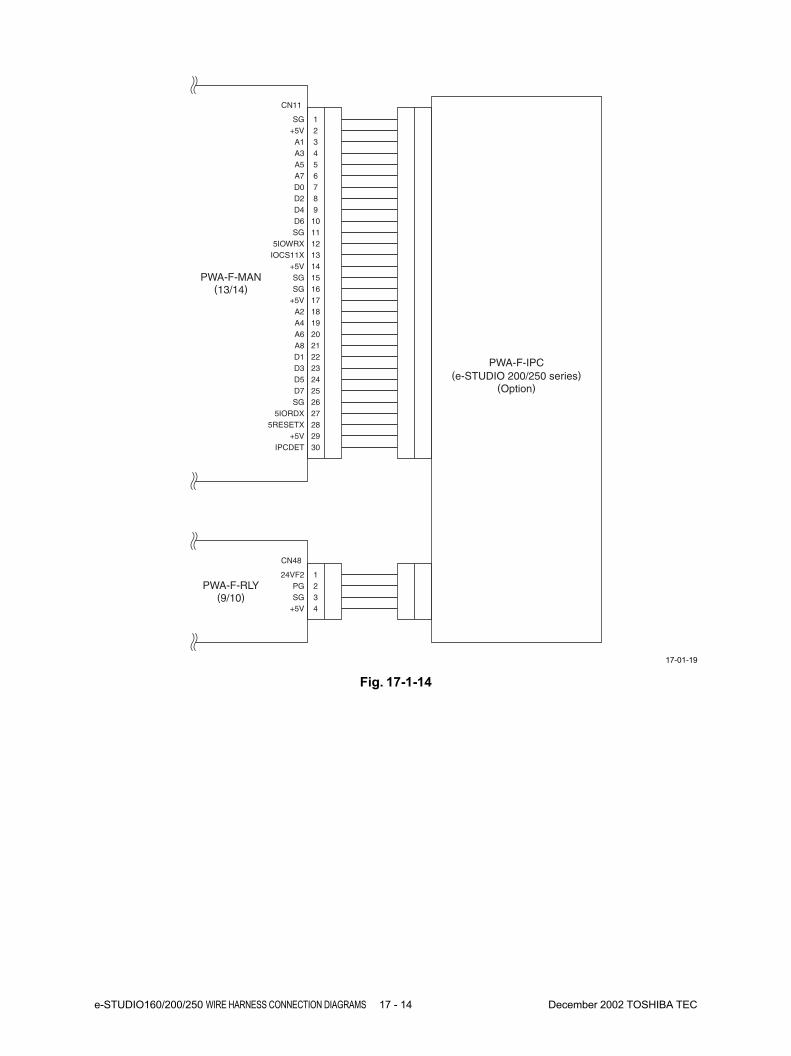
e-STUDIO160/200/250 WIRE HARNESS CONNECTION DIAGRAMS 17 - 14 December 2002 TOSHIBA TEC
CN11
PWA-F-IPC(e-STUDIO 200/250 series)
(Option)
PWA-F-MAN(13/14)
PWA-F-RLY(9/10)
24VF2 1
SGPG 2
3+5V 4
CN48
+5VSG 1
2
A3A1 3
4
A7A5 5
6
D2D0 7
8
D6D4 9
10
5IOWRXSG 11
12
+5VIOCS11X 13
14
SGSG 15
16
A2+5V 17
18
A6A4 19
20
D1A8 21
22
D5D3 23
24
SGD7 25
26
5RESETX5IORDX 27
28
IPCDET+5V 29
30
Fig. 17-1-14
17-01-19
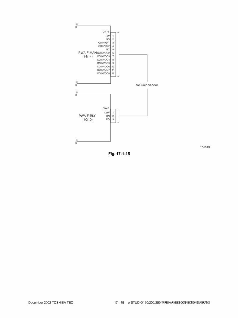
December 2002 TOSHIBA TEC 17 - 15 e-STUDIO160/200/250 WIRE HARNESS CONNECTION DIAGRAMS
CN16
for Coin vendor
PWA-F-MAN(14/14)
PWA-F-RLY(10/10)
+24V 1
PGON 2
3
CN42
SG+5V 1
2
COINVDI2COINVDI1 3
4
COINVDO2NC 5
6
COINVDO4COINVDO3 7
8
COINVDO6COINVDO5 9
10
COINVDO8COINVDO7 11
12
Fig. 17-1-15
17-01-20
18. PAGE MEMORY BOARD ......................... 18-1
18.1 Introduction ............................................................................................... 18-1
18.2 Structure ................................................................................................... 18-2
18.2.1 Interfaces ..................................................................................... 18-2
18.2.2 Schematic .................................................................................... 18-3
18.3 Description of Function ............................................................................. 18-5
18.3.1 Basic functions ............................................................................. 18-5
18.3.2 Editing .......................................................................................... 18-10
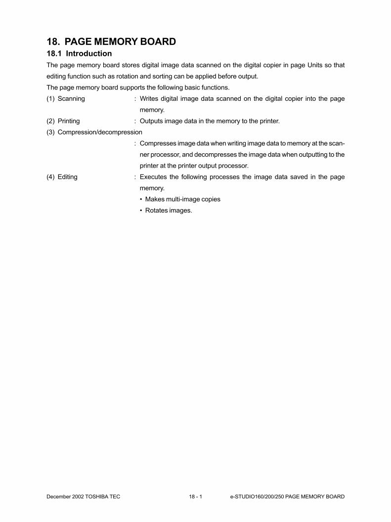
December 2002 TOSHIBA TEC 18 - 1 e-STUDIO160/200/250 PAGE MEMORY BOARD
18. PAGE MEMORY BOARD18.1 Introduction
The page memory board stores digital image data scanned on the digital copier in page Units so that
editing function such as rotation and sorting can be applied before output.
The page memory board supports the following basic functions.
(1) Scanning : Writes digital image data scanned on the digital copier into the page
memory.
(2) Printing : Outputs image data in the memory to the printer.
(3) Compression/decompression
: Compresses image data when writing image data to memory at the scan-
ner processor, and decompresses the image data when outputting to the
printer at the printer output processor.
(4) Editing : Executes the following processes the image data saved in the page
memory.
• Makes multi-image copies
• Rotates images.
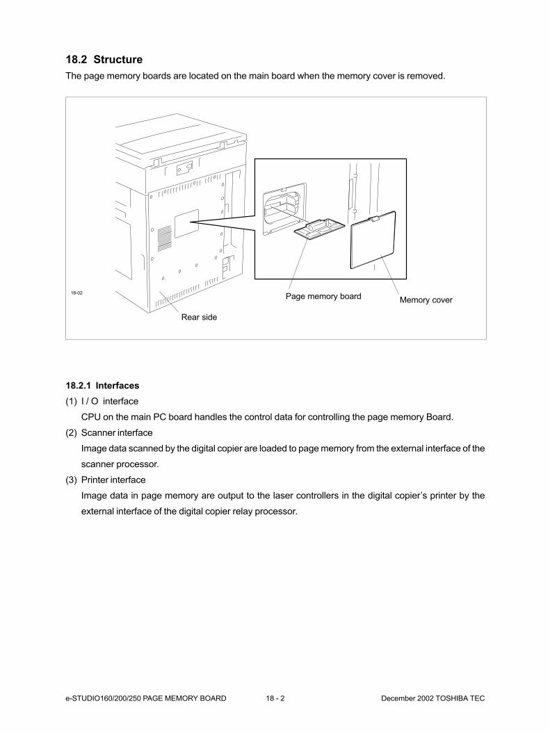
e-STUDIO160/200/250 PAGE MEMORY BOARD 18 - 2 December 2002 TOSHIBA TEC
18.2 Structure
The page memory boards are located on the main board when the memory cover is removed.
18.2.1 Interfaces
(1) I / O interface
CPU on the main PC board handles the control data for controlling the page memory Board.
(2) Scanner interface
Image data scanned by the digital copier are loaded to page memory from the external interface of the
scanner processor.
(3) Printer interface
Image data in page memory are output to the laser controllers in the digital copier’s printer by the
external interface of the digital copier relay processor.
18-02
Memory coverPage memory board
Rear side

December 2002 TOSHIBA TEC 18 - 3 e-STUDIO160/200/250 PAGE MEMORY BOARD
Model HM5264405F-A60 or equivalent product
Access time 100 nS
Memory configuration 4194304 x 4 bits x 4 banks
Address Row address A0-A1
Column address A0-A9
Bank select address A12-A13
Refreshment cy 4096 cycle/64mS
18.2.2 Schematic
The figure below shows a schematic diagram of the page memory board.
Page Memory Board Schematic
(1) Page memory
32 MB of memory (DRAM) are mounted on the main board as standard.
The Option page memory board specification (DRAM)
The page memory board is provided with two slots for mounting the main PC Board.
Adding on this memory board increases the memory to 128 MB.
Control ASIC
I/O control
Address control
Data control
Rotation/merger control
Compression/decompression
I/O
Scanner
Printer
Page memory controller Page memory
Memory
SD-RAM
Standard 32MB
Extension slot (2)
Expanded memory board
Max 128MB
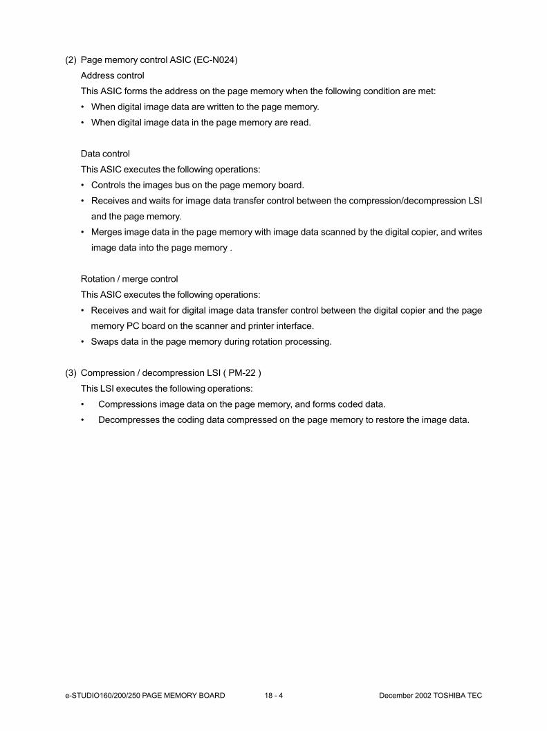
e-STUDIO160/200/250 PAGE MEMORY BOARD 18 - 4 December 2002 TOSHIBA TEC
(2) Page memory control ASIC (EC-N024)
Address control
This ASIC forms the address on the page memory when the following condition are met:
• When digital image data are written to the page memory.
• When digital image data in the page memory are read.
Data control
This ASIC executes the following operations:
• Controls the images bus on the page memory board.
• Receives and waits for image data transfer control between the compression/decompression LSI
and the page memory.
• Merges image data in the page memory with image data scanned by the digital copier, and writes
image data into the page memory .
Rotation / merge control
This ASIC executes the following operations:
• Receives and wait for digital image data transfer control between the digital copier and the page
memory PC board on the scanner and printer interface.
• Swaps data in the page memory during rotation processing.
(3) Compression / decompression LSI ( PM-22 )
This LSI executes the following operations:
• Compressions image data on the page memory, and forms coded data.
• Decompresses the coding data compressed on the page memory to restore the image data.

December 2002 TOSHIBA TEC 18 - 5 e-STUDIO160/200/250 PAGE MEMORY BOARD
18.3 Description of Function
18.3.1 Basic functions
(1) Alternation
This operation is achieved by the page memory board compression/decompression and rotation func-
tions. The orientation of multiple copies is switched for each copy or by each page at a time.
Alternation assumes that a cassette of the same paper size having a different orientation is installed
in the digital copier.
(2) Sort copying
This operation is achieved by the compression/ decompression function on the page memory while
being compressed. Image data stored in the memory are then decompressed at each page, and
printed. Assuming that printing of N number of copies has been set, decompression and printing at
each page are repeated for N number of times.
Example :
The following describes an example of execution process where alternation and sorting have been
specified when marking multi-copies.
Execution process (Basic function)
PM: Page Memory
Input
PM
Output
Memorymodule
Memorymodule
Scanner
Printer
PM
Input process
Output process
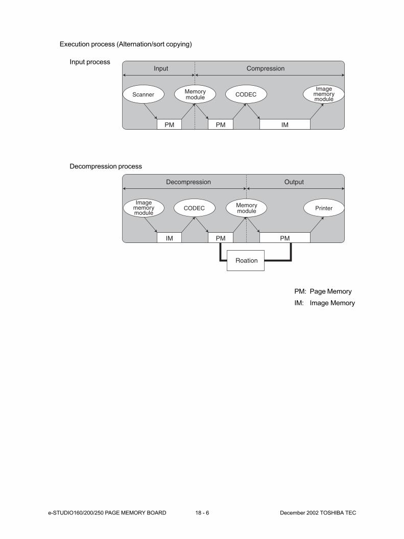
e-STUDIO160/200/250 PAGE MEMORY BOARD 18 - 6 December 2002 TOSHIBA TEC
IM PM PM
Decompression Output
PM PM IM
Input Compression
Roation
Imagememorymodule
Imagememorymodule
CODEC
CODEC Printer
Scanner Memorymodule
Memorymodule
Execution process (Alternation/sort copying)
Input process
Decompression process
PM: Page Memory
IM: Image Memory
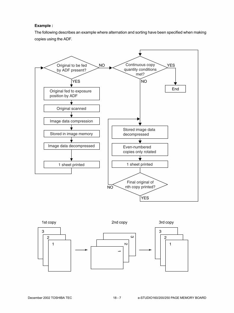
December 2002 TOSHIBA TEC 18 - 7 e-STUDIO160/200/250 PAGE MEMORY BOARD
Example :
The following describes an example where alternation and sorting have been specified when making
copies using the ADF.
NO YES
End
NO
YES
YES
NO
1
2
3
1
2
3
1
2
3
Original to be fedby ADF present?
Continuous copyquantity conditions
met?
Final original ofnth copy printed?
Original fed to exposure position by ADF
Original scanned
Image data compression
Stored image data decompressed
Even-numbered copies only rotated
1 sheet printed
Stored in image memory
Image data decompressed
1 sheet printed
1st copy 2nd copy 3rd copy

e-STUDIO160/200/250 PAGE MEMORY BOARD 18 - 8 December 2002 TOSHIBA TEC
(3) Magazine sorting
Sorts original in such a way a weekly magazine or newspaper can be made.
The following describes an example of execution process using the magazine sorting function.
Execution process (Magazine sorting)
Imagememorymodule
Imagememorymodule
Imagememorymodule
IM PM PM
2in 14in 1bind
Imagememorymodule
IM
Decompression Compression
PM PM IM
Input Compression
IM PM PM
Decompression Output
Rotation
CODEC
CODECScanner
CODEC Printer
CODECMemorymodule
Memorymodule
Memorymodule
Input process
Compression process
Decompression process
PM: Page Memory
IM: Image Memory
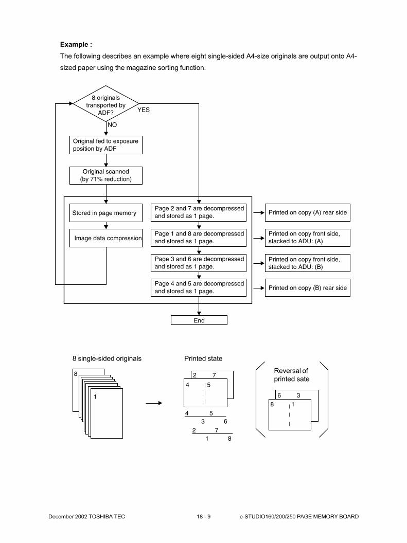
December 2002 TOSHIBA TEC 18 - 9 e-STUDIO160/200/250 PAGE MEMORY BOARD
8
1
4 5
4 53 6
2 71 8
2 7
38 1
6
YES
NO
8 originalstransported by
ADF?
Original fed to exposureposition by ADF
Original scanned(by 71% reduction)
Stored in page memory
Image data compression
Page 2 and 7 are decompressedand stored as 1 page.
Page 1 and 8 are decompressedand stored as 1 page.
Page 3 and 6 are decompressedand stored as 1 page.
Page 4 and 5 are decompressedand stored as 1 page.
Printed on copy (A) rear side
Printed on copy front side,stacked to ADU: (A)
Printed on copy front side,stacked to ADU: (B)
Printed on copy (B) rear side
End
Example :
The following describes an example where eight single-sided A4-size originals are output onto A4-
sized paper using the magazine sorting function.
8 single-sided originals Printed state
Reversal of
printed sate
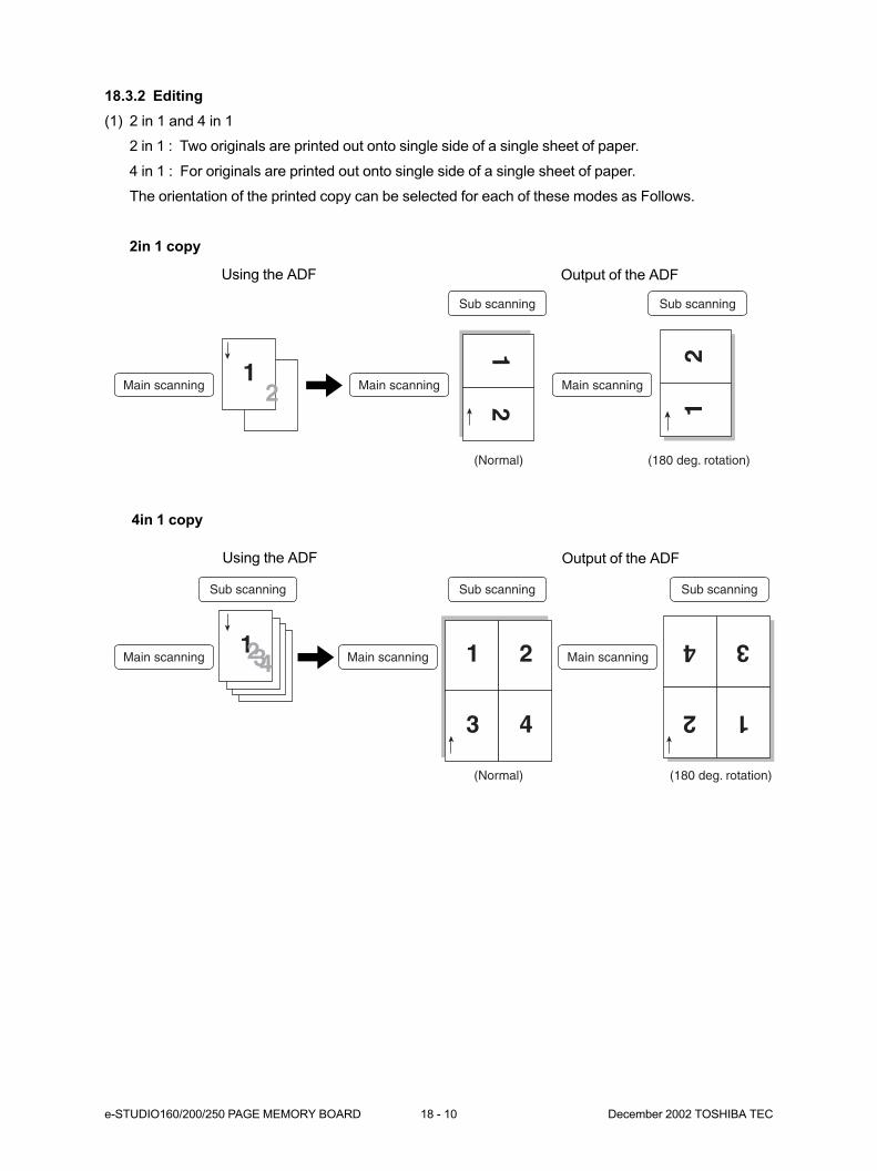
e-STUDIO160/200/250 PAGE MEMORY BOARD 18 - 10 December 2002 TOSHIBA TEC
18.3.2 Editing
(1) 2 in 1 and 4 in 1
2 in 1 : Two originals are printed out onto single side of a single sheet of paper.
4 in 1 : For originals are printed out onto single side of a single sheet of paper.
The orientation of the printed copy can be selected for each of these modes as Follows.
2in 1 copy
4in 1 copy
11
22 Main scanningMain scanning
Sub scanning
(Normal)
12
Main scanning
Sub scanning
(180 deg. rotation)
1 2
3 4
Main scanningMain scanning
Sub scanning
(Normal)
Sub scanning
12
34
Sub scanning
(180 deg. rotation)
Main scanning1
432
Using the ADF Output of the ADF
Using the ADF Output of the ADF

1-1, KANDA NISHIKI-CHO, CHIYODA-KU, TOKYO, 101-8842 JAPAN


![X SDC-888 - Citizen Systems · 123'456'789'012. 12.3456789012 0. 5.Price Mark-Up & Down Calculation 200+(P x 20%)=P P= 1 - 20% 200 = 250 250–200 = 50 200 [÷] 20 [MU] [MU] 250](https://img.dokumen.tips/doc/110x75/5fd9df3907c10b0ee2107e83/x-sdc-888-citizen-systems-123456789012-123456789012-0-5price-mark-up-.jpg)