Embed Size (px)
Citation preview
ECE 51112/16/2011
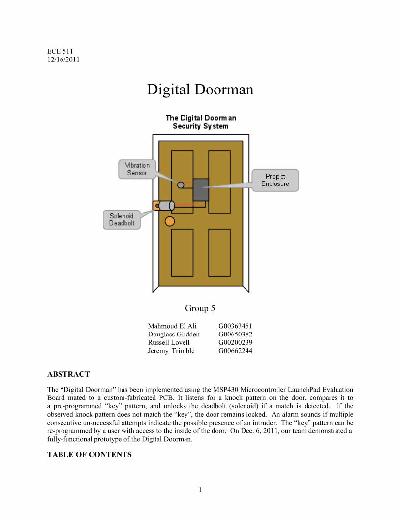
Digital Doorman
Group 5
Mahmoud El Ali G00363451Douglass Glidden G00650382Russell Lovell G00200239Jeremy Trimble G00662244
ABSTRACT
The “Digital Doorman” has been implemented using the MSP430 Microcontroller LaunchPad Evaluation Board mated to a custom-fabricated PCB. It listens for a knock pattern on the door, compares it to a pre-programmed “key” pattern, and unlocks the deadbolt (solenoid) if a match is detected. If the observed knock pattern does not match the “key”, the door remains locked. An alarm sounds if multiple consecutive unsuccessful attempts indicate the possible presence of an intruder. The “key” pattern can be re-programmed by a user with access to the inside of the door. On Dec. 6, 2011, our team demonstrated a fully-functional prototype of the Digital Doorman.
TABLE OF CONTENTS
1
ABSTRACTTABLE OF CONTENTSMOTIVATION / REQUIREMENTSSYSTEM DESCRIPTION
MODULE LISTFIRMWARE DESCRIPTION
KNOCK PATTERN RECOGNITIONKNOCK PATTERN LEARNINGDELAY FUNCTIONSSOFTWARE UARTBUZZER SOFTWARE
PROJECT MANAGEMENT AND REVISION CONTROLRESULTS AND LESSONS LEARNEDAPPENDIX
SYSTEM PART LISTTEAM TASKS
MAHMOUD EL ALIDOUGLASS GLIDDENRUSSELL LOVELLJEREMY TRIMBLE
SCHEMATICPCB LAYOUT
2
MOTIVATION / REQUIREMENTSThe "Digital Doorman” shall:
● Unlock a door when a designated knock rhythm is given.● Not incorrectly unlock the door due to observed noise that is not the pre-programmed knock
pattern.● Not be externally visible when the door is closed.● Provide visual feedback to the user to indicate the lock state and mode (LEDs).● Provide the ability to “learn” a new knock pattern entered by the user.
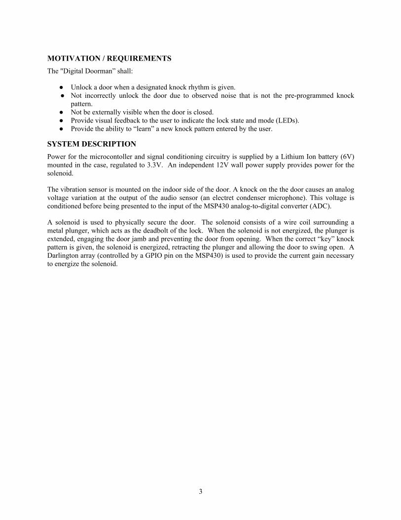
SYSTEM DESCRIPTIONPower for the microcontoller and signal conditioning circuitry is supplied by a Lithium Ion battery (6V) mounted in the case, regulated to 3.3V. An independent 12V wall power supply provides power for the solenoid.
The vibration sensor is mounted on the indoor side of the door. A knock on the the door causes an analog voltage variation at the output of the audio sensor (an electret condenser microphone). This voltage is conditioned before being presented to the input of the MSP430 analog-to-digital converter (ADC).
A solenoid is used to physically secure the door. The solenoid consists of a wire coil surrounding a metal plunger, which acts as the deadbolt of the lock. When the solenoid is not energized, the plunger is extended, engaging the door jamb and preventing the door from opening. When the correct “key” knock pattern is given, the solenoid is energized, retracting the plunger and allowing the door to swing open. A Darlington array (controlled by a GPIO pin on the MSP430) is used to provide the current gain necessary to energize the solenoid.
3
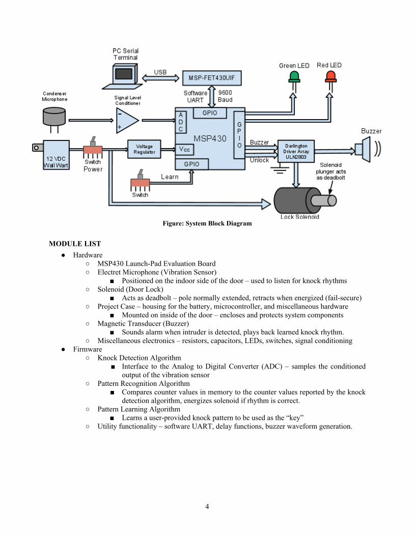
Figure: System Block Diagram
MODULE LIST● Hardware
○ MSP430 Launch-Pad Evaluation Board○ Electret Microphone (Vibration Sensor)
■ Positioned on the indoor side of the door – used to listen for knock rhythms○ Solenoid (Door Lock)
■ Acts as deadbolt – pole normally extended, retracts when energized (fail-secure)○ Project Case – housing for the battery, microcontroller, and miscellaneous hardware
■ Mounted on inside of the door – encloses and protects system components○ Magnetic Transducer (Buzzer)
■ Sounds alarm when intruder is detected, plays back learned knock rhythm.○ Miscellaneous electronics – resistors, capacitors, LEDs, switches, signal conditioning
● Firmware○ Knock Detection Algorithm
■ Interface to the Analog to Digital Converter (ADC) – samples the conditioned output of the vibration sensor
○ Pattern Recognition Algorithm■ Compares counter values in memory to the counter values reported by the knock
detection algorithm, energizes solenoid if rhythm is correct.○ Pattern Learning Algorithm
■ Learns a user-provided knock pattern to be used as the “key”○ Utility functionality – software UART, delay functions, buzzer waveform generation.
4
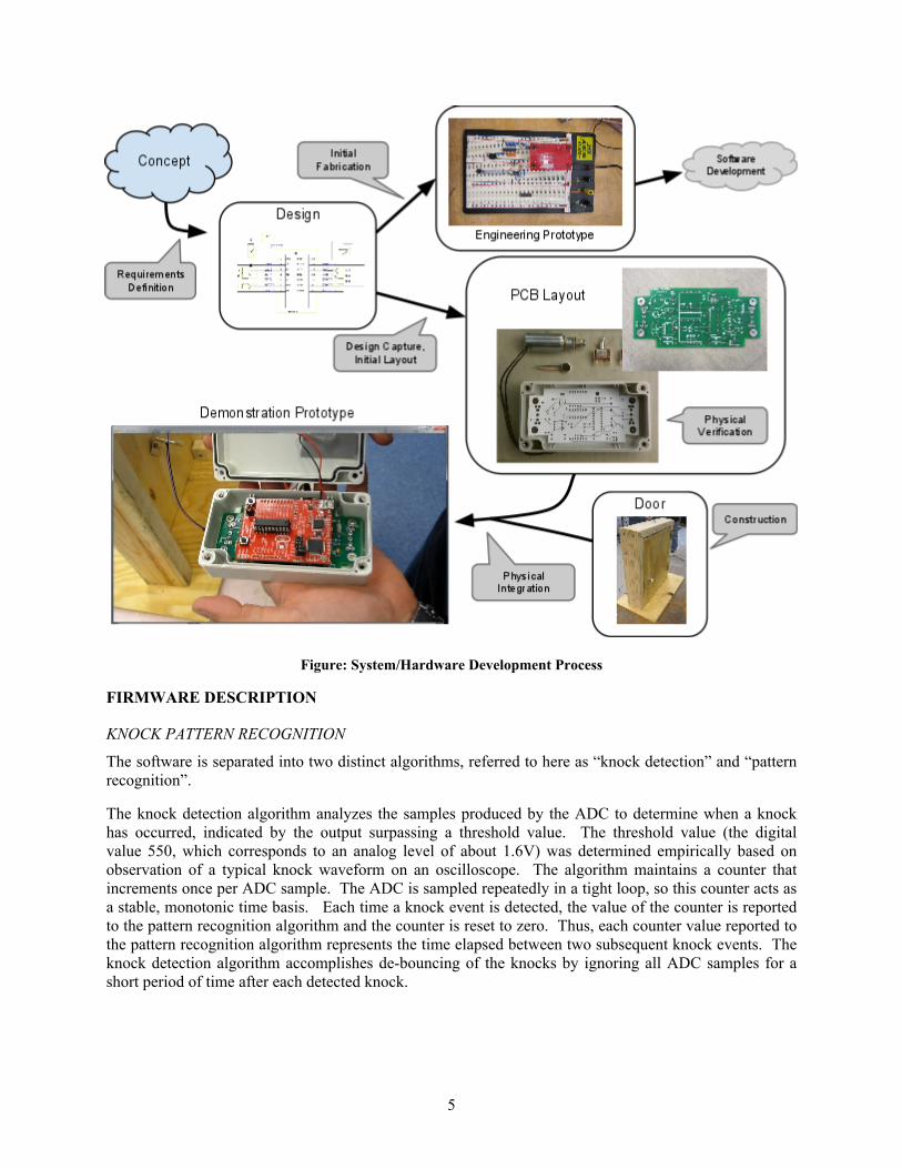
Figure: System/Hardware Development Process
FIRMWARE DESCRIPTION
KNOCK PATTERN RECOGNITION
The software is separated into two distinct algorithms, referred to here as “knock detection” and “pattern recognition”.
The knock detection algorithm analyzes the samples produced by the ADC to determine when a knock has occurred, indicated by the output surpassing a threshold value. The threshold value (the digital value 550, which corresponds to an analog level of about 1.6V) was determined empirically based on observation of a typical knock waveform on an oscilloscope. The algorithm maintains a counter that increments once per ADC sample. The ADC is sampled repeatedly in a tight loop, so this counter acts as a stable, monotonic time basis. Each time a knock event is detected, the value of the counter is reported to the pattern recognition algorithm and the counter is reset to zero. Thus, each counter value reported to the pattern recognition algorithm represents the time elapsed between two subsequent knock events. The knock detection algorithm accomplishes de-bouncing of the knocks by ignoring all ADC samples for a short period of time after each detected knock.
5
Figure: Detection and Recognition Algorithm Flow Diagram
The pattern recognition algorithm analyzes the stream of counter values reported by the knock detection algorithm and determines whether the observed knock pattern sufficiently matches the “key” pattern. If the observed pattern matches the “key” pattern, the door will be unlocked.
Since the pattern of a sequence of knocks is characterized by the duration of the time intervals between subsequent knock events, the “key” knock pattern is stored as an array of integers listing the duration (in ADC sample periods) between subsequent knock events in the “key” knock pattern. Put another way, the “key” knock pattern stored in memory is the first difference of the knock pattern as measured on some absolute timescale. The pattern recognition algorithm then simply compares the observed intervals between knock events to the “key” values stored in this array.
During initial testing, we found it quite difficult to get the software to accept the knock pattern and unlock. While drumming out the “correct” rhythm was not difficult, the algorithm required that this be done at a very precise speed (or “tempo” for the musically inclined), often requiring a metronome to calibrate the user’s pace.
To improve the usability of the system, we implemented a “tempo independence” enhancement. The interval between the first two detected knocks is used to calculate a fixed-point scaling factor that is applied to the key to allow for variance in the tempo of the knock pattern. An 8-bit scaling factor is used with 4 bits to the left of the “virtual decimal point,” allowing 256 different fractional scaling factors (from 16 times faster down to 1/16th the speed of the “key” knock pattern given in memory). For each subsequent detected knock event, if the duration since the previous knock event matches the scaled value in the “key” array (within a small tolerance), the knock is accepted and the pattern recognition algorithm proceeds to the next value in the “key” array. If a knock event does not occur within the expected
6
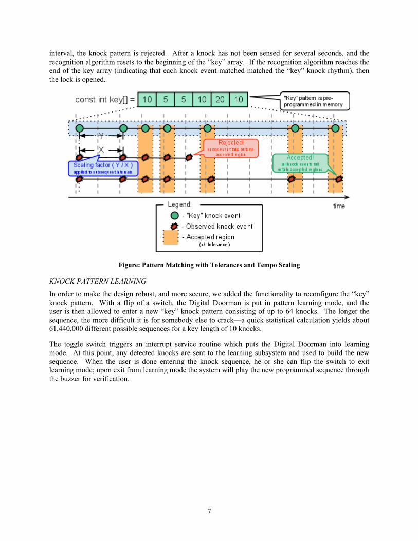
interval, the knock pattern is rejected. After a knock has not been sensed for several seconds, and the recognition algorithm resets to the beginning of the “key” array. If the recognition algorithm reaches the end of the key array (indicating that each knock event matched matched the “key” knock rhythm), then the lock is opened.
Figure: Pattern Matching with Tolerances and Tempo Scaling
KNOCK PATTERN LEARNING
In order to make the design robust, and more secure, we added the functionality to reconfigure the “key” knock pattern. With a flip of a switch, the Digital Doorman is put in pattern learning mode, and the user is then allowed to enter a new “key” knock pattern consisting of up to 64 knocks. The longer the sequence, the more difficult it is for somebody else to crack—a quick statistical calculation yields about 61,440,000 different possible sequences for a key length of 10 knocks.
The toggle switch triggers an interrupt service routine which puts the Digital Doorman into learning mode. At this point, any detected knocks are sent to the learning subsystem and used to build the new sequence. When the user is done entering the knock sequence, he or she can flip the switch to exit learning mode; upon exit from learning mode the system will play the new programmed sequence through the buzzer for verification.
7
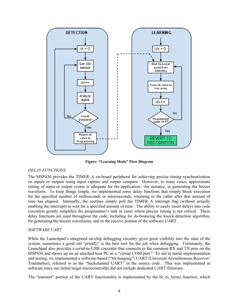
Figure: “Learning Mode” Flow Diagram
DELAY FUNCTIONSThe MSP430 provides the TIMER_A on-board peripheral for achieving precise timing synchronization on inputs or outputs using input capture and output compare. However, in many cases, approximate timing of input or output events is adequate for the application—for instance, in generating the buzzer waveform. To keep things simple, we implemented some delay functions that simply block execution for the specified number of milliseconds or microseconds, returning to the caller after that amount of time has elapsed. Internally, the routines simply poll the TIMER_A interrupt flag (without actually enabling the interrupt) to wait for a specified amount of time. The ability to easily insert delays into code execution greatly simplifies the programmer’s task in cases where precise timing is not critical. These delay functions are used throughout the code, including for de-bouncing the knock detection algorithm, for generating the buzzer waveforms, and in the receive portion of the software UART.
SOFTWARE UART
While the Launchpad’s integrated on-chip debugging circuitry gives great visibility into the state of the system, sometimes a good old “printf()” is the best tool for the job when debugging. Fortunately, the Launchpad also provides a serial-to-USB converter that connects to the common RX and TX pins on the MSP430 and shows up on an attached host PC as a “virtual COM port.” To aid in initial implementation and testing, we implemented a software-based (“bit-banging”) UART (Universal Asynchronous Receiver/Transmitter), referred to as the “backchannel UART” in the source code. This was implemented in software since our initial target microcontroller did not include dedicated UART firmware.
The “transmit” portion of the UART functionality is implemented by the bc_tx_byte() function, which
8
utilizes the MSP430’s TIMER_A output compare capability to “clock out” each bit of a single byte at 9600 baud, 8 data bits, 1 start bit, 1 stop bit, and no parity. Building on the bc_tx_byte() primitive, we implemented a simple version of the common “printf()” C routine, which we call bc_printf(). bc_printf() accepts a format string with an arbitrary number of parameters (using the C variadic functions paradigm), and supports the “%d”, “%u”, and “%x” formatting strings for printing 8 and 16-bit signed or unsigned integers in decimal or hexadecimal format, and the “%c” format string for substituting single characters into the output.
A “receive” functionality was also implemented, which triggers an interrupt on the falling edge of a start bit on the RX pin. Once inside the ISR, the delay_microseconds() function is used to sample the state of the RX pin at the center of each bit period, minimizing the likelihood of inter-symbol interference. Once the 8 bits and associated framing bits have been read in, the received byte is stored into a 16-byte ring buffer, allowing the received data to be retrieved asynchronously through a call to the bc_rx_byte() function. Although the receive functionality was tested and working, we ultimately never used it for anything.
BUZZER SOFTWARE
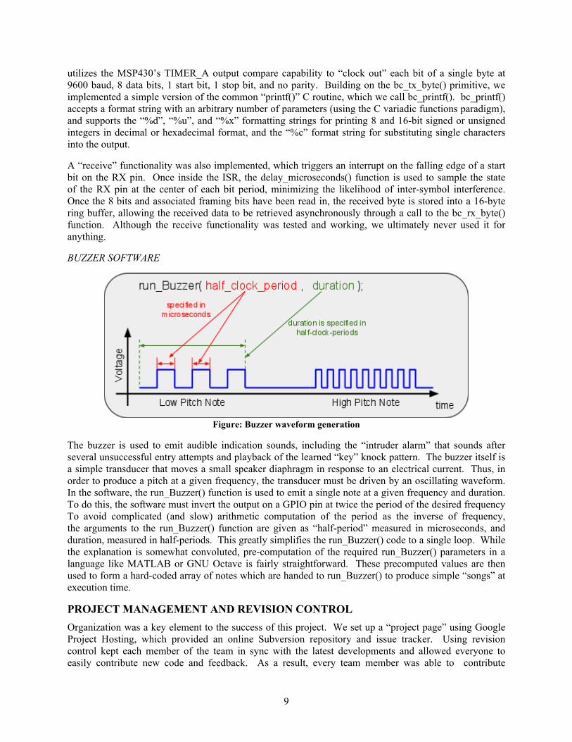
Figure: Buzzer waveform generation
The buzzer is used to emit audible indication sounds, including the “intruder alarm” that sounds after several unsuccessful entry attempts and playback of the learned “key” knock pattern. The buzzer itself is a simple transducer that moves a small speaker diaphragm in response to an electrical current. Thus, in order to produce a pitch at a given frequency, the transducer must be driven by an oscillating waveform. In the software, the run_Buzzer() function is used to emit a single note at a given frequency and duration. To do this, the software must invert the output on a GPIO pin at twice the period of the desired frequency To avoid complicated (and slow) arithmetic computation of the period as the inverse of frequency, the arguments to the run_Buzzer() function are given as “half-period” measured in microseconds, and duration, measured in half-periods. This greatly simplifies the run_Buzzer() code to a single loop. While the explanation is somewhat convoluted, pre-computation of the required run_Buzzer() parameters in a language like MATLAB or GNU Octave is fairly straightforward. These precomputed values are then used to form a hard-coded array of notes which are handed to run_Buzzer() to produce simple “songs” at execution time.
PROJECT MANAGEMENT AND REVISION CONTROLOrganization was a key element to the success of this project. We set up a “project page” using Google Project Hosting, which provided an online Subversion repository and issue tracker. Using revision control kept each member of the team in sync with the latest developments and allowed everyone to easily contribute new code and feedback. As a result, every team member was able to contribute
9

significantly to the software development process—this project was a true “team effort.” Recording tasks and accomplishments in the issue tracker helped us get a sense of our progress toward the “big picture” goals of the project. Our issue tracker and source code repository are available to the public at: https://code.google.com/p/ece511-fall2011-group5/. As of our final release on December 6, 2011, our codebase had grown to over 1,000 lines of code with 83 separate commits, and 14 different tracked and resolved issues.
RESULTS AND LESSONS LEARNED
On Tuesday, December 6, 2011, a semester’s worth of development culminated in the successful demonstration of the Digital Doorman to our ECE511 classmates. After a short presentation that described the overall system and our progress, we successfully demonstrated the operation of the digital doorman, including accepted and rejected knock patterns, the intruder alarm, and the “learning” mode. All requirements were tested and met.
Our team overcame technical hurdles during development. About a month and a half into development we were no longer able to fit our compiled code within the 2 kB of Flash memory available on the MSP430G2231. We evaluated options and chose to upgrade to the MSP430G2533, a 20-pin variant of the MSP430 Value Line with 16 kB of memory. Integration of this new hardware with our existing software was largely seamless, though a few minor software changes were required.
One of the biggest challenges was finding the time to work on the project—each member of the team worked full-time or was taking several classes this semester. Establishing a revision control system early in the project to track and coordinate our development made it easy for team members to contribute when spare time opportunities arose.
10
APPENDIX
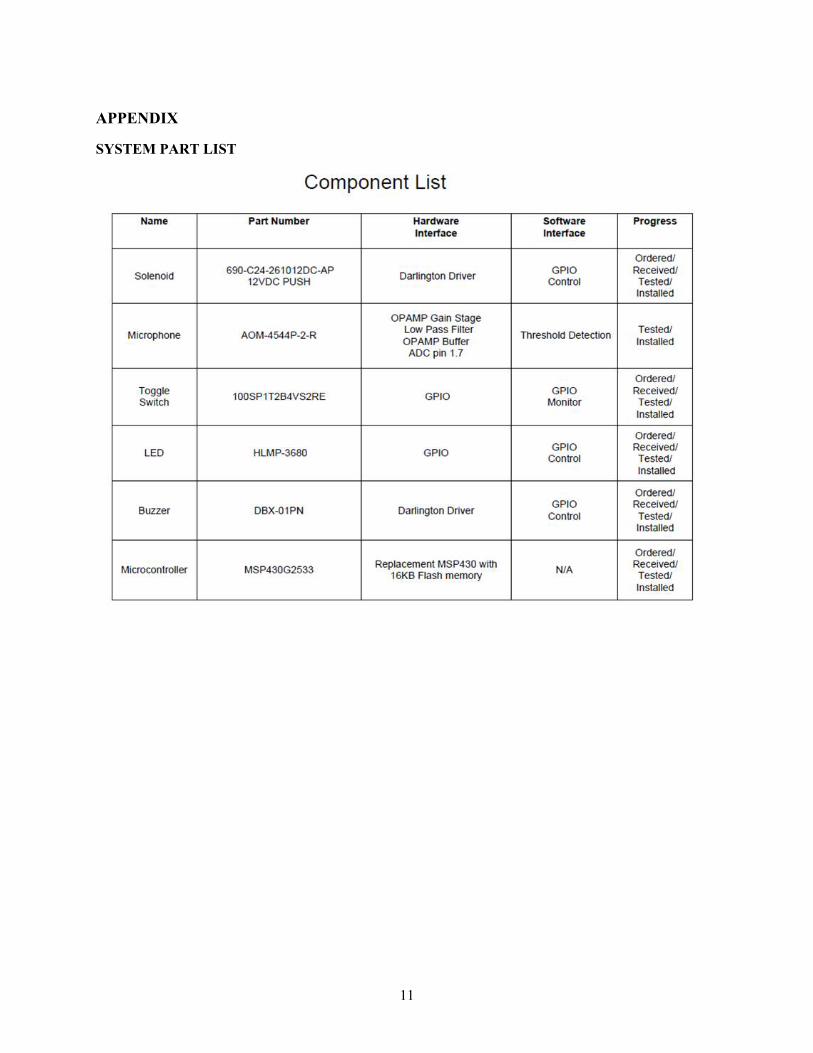
SYSTEM PART LIST
11
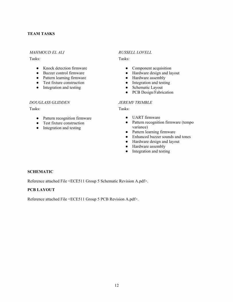
TEAM TASKS
MAHMOUD EL ALITasks:
● Knock detection firmware● Buzzer control firmware● Pattern learning firmware● Test fixture construction● Integration and testing
DOUGLASS GLIDDENTasks:
● Pattern recognition firmware● Test fixture construction● Integration and testing
RUSSELL LOVELLTasks:
● Component acquisition● Hardware design and layout● Hardware assembly● Integration and testing● Schematic Layout● PCB Design/Fabrication
JEREMY TRIMBLETasks:
● UART firmware● Pattern recognition firmware (tempo
variance)● Pattern learning firmware● Enhanced buzzer sounds and tones● Hardware design and layout● Hardware assembly● Integration and testing
SCHEMATIC
Reference attached File <ECE511 Group 5 Schematic Revision A.pdf>.
PCB LAYOUT
Reference attached File <ECE511 Group 5 PCB Revision A.pdf>.
12