Embed Size (px)
Citation preview
JOURNAL OF THE OPTICAL SOCIETY OF AMERICA
Diffraction patterns of simple apertures
Richard C. Smith and James S. MarshDepartnent of Physics, The University of West Florida, Pensacola, Florida 32504
(Received 30 August 1973)
The Fraunhofer diffraction patterns of the triangle, trapezoid, and hexagon are calculated and displayed inmoir6 plots. The diffraction pattern of the general polygonal aperture with a finite number of vertices canbe calculated in terms of elementary functions.
Index Headings: Diffraction; Fourier transforms; Moir&
It is well known that the Fraunhofer diffraction patternof an aperture is given by the two-dimensional Fouriertransform of that aperture. Optics textbooks" 2 generallytreat only two specific examples, rectangular andcircular apertures, and perhaps unwittingly leave theimpression that other apertures cannot be treatedsimply or exactly. We have seen only one text' inwhich the diffraction pattern of the general aperture isdiscussed, and that treatment is only a qualitativeone.
We show in Sec. I that the Fourier transform of anisosceles triangle can be expressed in terms of simplefunctions; similar results are discussed for the trapezoidand hexagon in Secs. II and III. The approach to thegeneral N-sided aperture is discussed in Sec. IV.
The calculated diffraction patterns are presentedvisually with a moire technique, discussed in theAppendix. These results were calculated and drawn ona desk-top calculator system (Hewlett-Packard 9100Bwith plotter) which demonstrates that neither a largegraphics computer terminal nor the complication ofthe fast-Fourier-transform algorithm is necessary topredict the diffraction patterns of simple apertures.Indeed, comparisons of actual diffraction patterns withthe accompanying photographs show that astonishingdetail can be depicted with this simple technique.
OBJECT O(xy)
PLANE WAVElY
TRANSFORMING LENS,FOCAL LENGTH f
d FOURIER PL
r.'
ANE
I. THE ISOSCELES TRIANGLE
If an aperture is illuminated with a plane wave ofwavelength A and unit amplitude, and an observingscreen is placed in the focal plane of a positive lens,as shown in Fig. 1, the amplitude at the screen, calledthe Fourier plane, is 4
A%-q)=-exp 1- 1- Q(t + ,72)]
Xf O(x,y) exp[-2iri(xt+yti)/(fX)] dx dy, (1)Aperture
where O(x,y) =1 or 0, according to whether the point(xy) is inside or outside the aperture. The factoroutside the integral can be ignored if only relativeirradiances are to be computed. If it is important thatthe wave front be plane, as for instance in holographicor spatial-filtering applications, this is easily achievedby placing the object aperture in the front focal. planeof the lens, so that d = f. In any case, we ignore thecoefficient of the integral hereafter. Make the coor-dinate-scaling transformations
X = (27r/fX)t, (2)
Y = (2 7r/fX),q;
then the diffraction integral becomes
A(X,Y)= fO(x,y) exp[-i(xX+yY)] dx dy. (3)
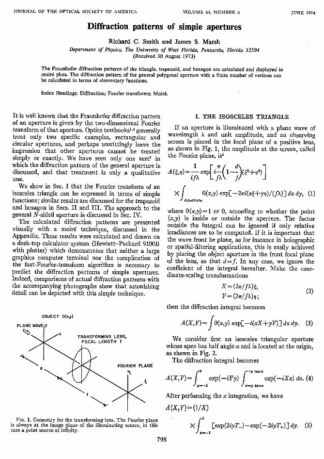
We consider first an isosceles triangular aperturewhose apex has half angle a and is located at the origin,as shown in Fig. 2.
The diffraction integral becomes
0kA (X, Y)=J
vi
y tana
exp(-iYy) uta exp(-iXx) dx. (4)
After performing the x integration, we have
A (XI Y) = (1/X)
FIG. 1. Geometry for the transforming lens. The Fourier planeis always at the image plane of the illuminating source, in thiscase a point source at infinity.
798
X Eexp(2iyT-)-exp(-2iyT+)] dy. (5)1
VOLUME 64. NUMBER 6 JUNE 1974
f
"11�
DIFFRACTION PATTERNS OF SIMPLE APERTURES
whereT4,= (X tanacv Y)/2. (6)
We have omitted, as usual, constant coefficients ofthe integral. The integral of Eq. (5) is readily evaluatedto give (except for a phase factor)
A(X,Y)= (1/X)
sinT+ sinT-X exp(iT+)--exp(-iT-)-=. (7)
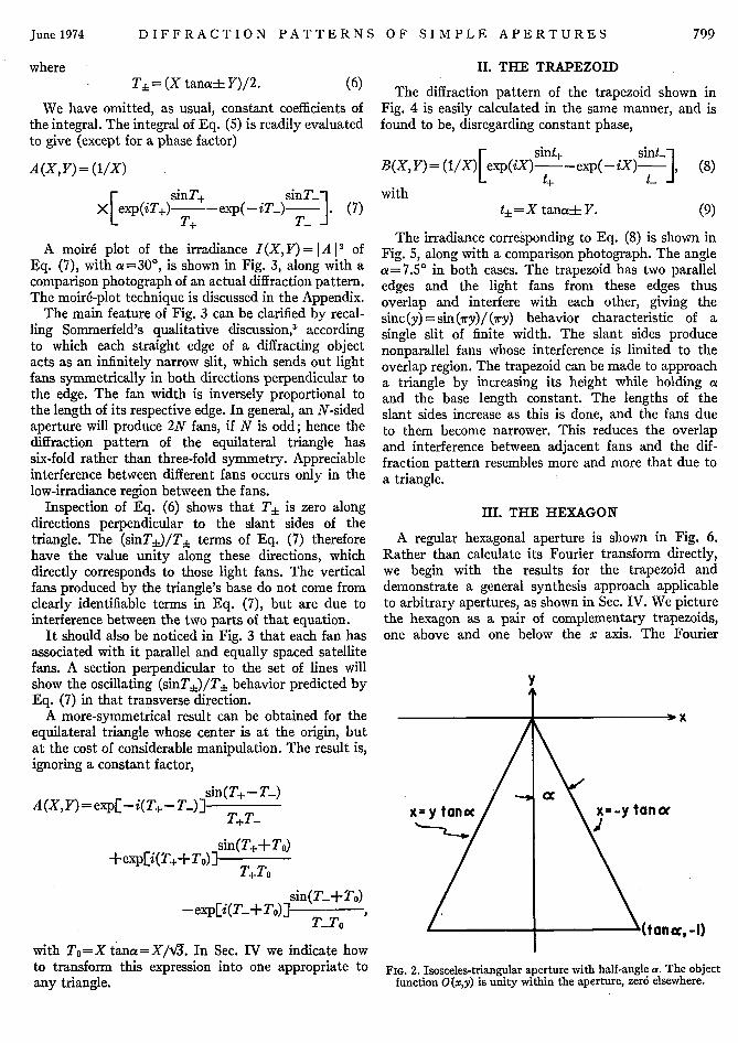
A moire plot of the irradiance I(X, Y) = IA 12 ofEq. (7), with a=30', is shown in Fig. 3, along with acomparison photograph of an actual diffraction pattern.The moir6-plot technique is discussed in the Appendix.
The main feature of Fig. 3 can be clarified by recal-ling Sommerfeld's qualitative discussion,3 accordingto which each straight edge of a diffracting objectacts as an infinitely narrow slit, which sends out lightfans symmetrically in both directions perpendicular tothe edge. The fan width is inversely proportional tothe length of its respective edge. In general, an N-sidedaperture will produce 2N fans, if N is odd; hence thediffraction pattern of the equilateral triangle hassix-fold rather than three-fold symmetry. Appreciableinterference between different fans occurs only in thelow-irradiance region between the fans.
Inspection of Eq. (6) shows that T7 is zero alongdirections perpendicular to the slant sides of thetriangle. The (sinT±)/T+ terms of Eq. (7) thereforehave the value unity along these directions, whichdirectly corresponds to those light fans. The verticalfans produced by the triangle's base do not come fromclearly identifiable terms in Eq. (7), but are due tointerference between the two parts of that equation.
It should also be noticed in Fig. 3 that each fan hasassociated with it parallel and equally spaced satellitefans. A section perpendicular to the set of lines willshow the oscillating (sinT±)/T± behavior predicted byEq. (7) in that transverse direction.
A more-symmetrical result can be obtained for theequilateral triangle whose center is at the origin, butat the cost of considerable manipulation. The result is,ignoring a constant factor,
sin(T+- T-)A(X, Y) = exp[-i(T+-T4)]
sin(T++ To)+exp[i(T++To)] sT3 T
T+To
-exp[i(T +To)]- nT- o)
II. THE TRAPEZOID
The diffraction pattern of the trapezoid shown inFig. 4 is easily calculated in the same manner, and isfound to be, disregarding constant phase,
sint+ sint-~B(X,Y)= (1/X) exp(iX) -exp(-iX)],
witht+ =X tanaL Y.
(8)
(9)
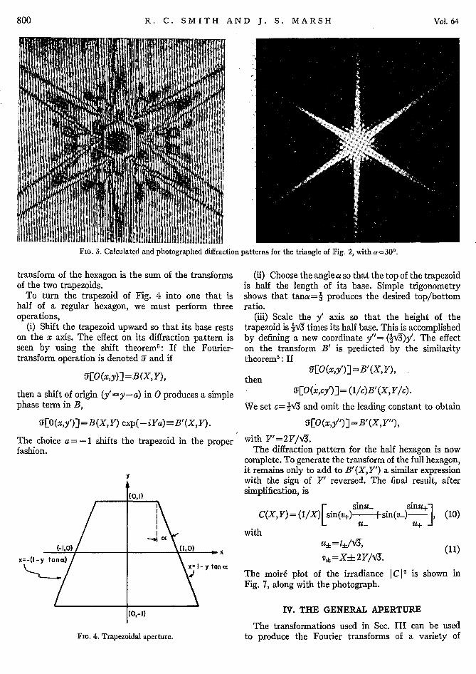
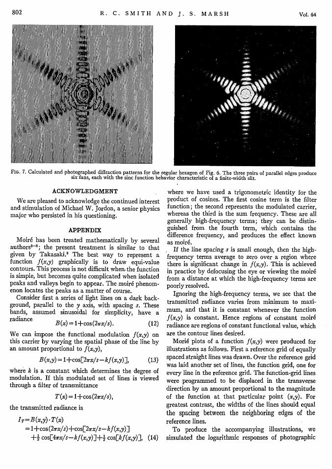
The irradiance corresponding to Eq. (8) is shown inFig. 5, along with a comparison photograph. The anglea=7.5° in both cases. The trapezoid has two paralleledges and the light fans from these edges thusoverlap and interfere with each other, giving thesinc(y)=sin(lry)/(iry) behavior characteristic of asingle slit of finite width. The slant sides producenonparallel fans whose interference is limited to theoverlap region. The trapezoid can be made to approacha triangle by increasing its height while holding aand the base length constant. The lengths of theslant sides increase as this is done, and the fans dueto them become narrower. This reduces the overlapand interference between adjacent fans and the dif-fraction pattern resembles more and more that due toa triangle.
III. THE HEXAGON
A regular hexagonal aperture is shown in Fig. 6.Rather than calculate its Fourier transform directly,we begin with the results for the trapezoid anddemonstrate a general synthesis approach applicableto arbitrary apertures, as shown in Sec. IV. We picturethe hexagon as a pair of complementary trapezoids,one above and one below the x axis. The Fourier
x
,tanc, -I)with To=X tana=X/V3. In Sec. IV we indicate how Ito transform this expression into one appropriate to FIG. 2. Isosceles-triangular aperture with half-angle a. The objectany triangle. - function 0 (x,y) is unity within the aperture, zer6 elsewhere.
799June 1974
R. C. SMITH AND J. S. MARSH
FIG. 3. Calculated and photographed diffraction patterns for the triangle of Fig. 2, with a=30'.
transform of the hexagon is the sum of the transformsof the two trapezoids.
To turn the trapezoid of Fig. 4 into one that ishalf of a regular hexagon, we must perform threeoperations,
(i) Shift the trapezoid upward so that its base restson the x axis. The effect on its diffraction pattern isseen by using the shift theorem': If the Fourier-transform operation is denoted 5Y and if
9EO(x,y)]=B(X,Y),
then a shift of origin (y' =y-a) in 0 produces a simplephase term in B,
9E;O (x,y')] = B(X, Y) exp(-iYa) a B'(X, Y) .
The choice a= -1 shifts the trapezoid in the properfashion.
(0,1)
I\-I\
(1a x- x
y tanoc
FIG. 4. Trapezoidal aperture.
(ii) Choose the angle a so that the top of the trapezoidis half the length of its base. Simple trigonometryshows that tana= 4 produces the desired top/bottomratio.
(iii) Scale the y' axis so that the height of thetrapezoid is 4V3 times its half base. This is accomplishedby defining a new coordinate y"= (4VZ)y'. The effecton the transform B' is predicted by the similaritytheorem': If
9EO(xY')]=B'(xXY),then
9EO(x,cy')3= (llc)B'(X,Ylc).
We set c= 4V3 and omit the leading constant to obtain
S:[O(x,y"')] =B'(X,Y"),
with Y'=2Y/IV.The diffraction pattern for the half hexagon is now
complete. To generate the transform of the full hexagon,it remains only to add to B'(X, Y') a similar expressionwith the sign of Y' reversed. The final result, aftersimplification, is
sinu- Sin+C(X,Y)= (1/X) sin(v+)- +sin(v-) , (10)
- -Muwith
v t/, X-4- 2(11)v+=Xht 2V/Vl.
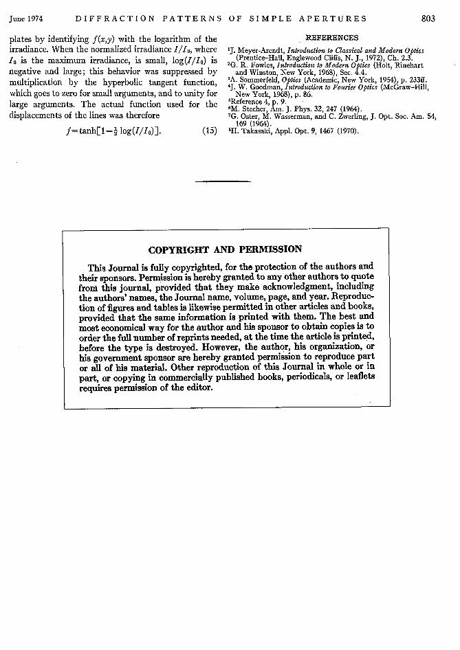
The moir6 plot of the irradiance IC 2 is shown inFig. 7, along with the photograph.
IV. THE GENERAL APERTURE
The transformations used in Sec. III can be usedto produce the Fourier transforms of a variety of
800 'Vol. 64
I

DIFFRACTION PATTERNS OF SIMPLE APERTURES
FIG. 5. Calculated and photographed diffraction patterns for the trapezoid of Fig. 4, with a = 7.5°. The light fans from the parallel topand bottom edges overlap completely, with resulting sinc(y) =sin(iry)/7ry behavior.
apertures from the simple regular figures of the pre-ceding sections. The simplest transformations arerotations, translations, and scale changes of theaperture, whose effects on the transform are, respec-tively, rotation, linear phase-factor multiplication, andreciprocal scale change. These transformations produceapertures similar to the original apertures; the corre-sponding diffraction patterns are geometrically similarto the original diffraction patterns.
Nonsimilar apertures can be produced by uniformscaling, i.e., by shrinking or stretching, along a givendirection. The effect on the diffraction pattern is toscale it along a parallel axis but in the reciprocalsense. For example, the equilateral triangle of Fig. 2may be transformed into an obtuse isosceles triangleby shrinking it along the y axis (or stretching along thex axis). The corresponding change of the diffractionpattern is a scaling in the reciprocal sense. It is stretchedalong the Y axis. The scaling axis may point in whateverdirection is required. Thus, a square may be transformedinto a rhombus by dilating along a line joining twoopposite vertices.
It is evident that the diffraction pattern of anarbitrary triangle can be obtained from that of theequilateral triangle by a succession of such transforma-tions, with corresponding changes of the diffractionpatterns, as illustrated in Sec. III. Because an arbitrarypolygonal aperture, i.e., an aperture whose edges aremade up of a finite number of straight line segments,can be triangulated by a finite number of triangles,the Fourier transform can be represented as the sum oftransforms of the triangles. This means that thediffraction pattern of an arbitrary polygonal aperturecan be represented by a finite number of terms involvingonly elementary functions.
V. CONCLUSION
We have shown that Fraunhofer diffraction patternsof polygonal apertures (in addition to the traditionalslit and pinhole) can be easily calculated, and we haveillustrated a graphical technique accessible to anyonewith a desk-top calculator and plotter.
FIG. 6. Regular hexagonal aperture, shown divided into twocomplementary trapezoids. The trapezoid of Fig. 4 is translatedand stretched as required to correspond to the comparativedimensions shown here.
801June 1974
R. C. SMITH AND J. S. MARSH
FIG. 7. Calculated and photographed diffraction patterns for the regular hexagon of Fig. 6. The three pairs of parallel edges producesix fans, each with the sinc function behavior characteristic of a finite-width slit.
ACKNOWLEDGMENT
We are pleased to acknowledge the continued interestand stimulation of Michael W. Jordon, a senior physicsmajor who persisted in his questioning.
APPENDIX
Moir6 has been treated mathematically by severalauthors> 8 ; the present treatment is similar to thatgiven by Takasaki.8 The best way to represent afunction f (x,y) graphically is to draw equi-valuecontours. This process is not difficult when, the functionis simple, but becomes quite complicated when isolatedpeaks and valleys begin to appear. The moir6 phenom-enon locates the peaks as a matter of course.
Consider first a series of light lines on a dark back-ground, parallel to the y axis, with spacing s. Thesebands, assumed sinusoidal for simplicity, have a
radiance B(x) = 1+cos(2vrx/s). (12)
We can impose the functional modulation f(xy) onthis carrier by varying the spatial phase of the line byan amount proportional to f (x,y),
B(x,y) = 1+cos[27rx/s-kf (x,y)j, (13)
where k is a constant which determines the degree ofmodulation. If this modulated set of lines is viewedthrough a filter of transmittance
T(x) = 1+cos(27rx/s),
the transmitted radiance is
IT=B (x,y) . T (x)= 1+cos(2irx/s) +cos[27rx/s-kf (x,y)]
+41 cos[47rx/s-kf(x,y)J+' cos[kf(x,y)], (14)
where we have used a trigonometric identity for theproduct of cosines. The first cosine term is the filterfunction; the second represents the modulated carrier,whereas the third is the sum frequency. These are allgenerally high-frequency terms; they can be distin-guished from the fourth term, which contains thedifference frequency, and produces the effect knownas moir6.
If the line spacing s is small enough, then the high-frequency terms average to zero over a region wherethere is significant change in f(x,y). This is achievedin practice by defocusing the eye or viewing the moir6from a distance at which the high-frequency terms arepoorly resolved.
Ignoring the high-frequency terms, we see that thetransmitted radiance varies from minimum to maxi-mum, and that it is constant whenever the functionf(x,y) is constant. Hence regions of constant moireradiance are regions of constant functional value, whichare the contour lines desired.
Mori6 plots of a function f(x,y) were produced forillustrations as follows. First a reference grid of equallyspaced straight lines was drawn. Over the reference gridwas laid another set of lines, the function grid, one forevery line in the reference grid. The function-grid lineswere programmed to be displaced in the transversedirection by an amount proportional to the magnitudeof the function at that particular point (x,y). Forgreatest contrast, the widths of the lines should equalthe spacing between the neighboring edges of thereference lines.
To produce the accompanying illustrations, wesimulated the logarithmic responses of photographic
802 Vol. 64
DIFFRACTION PATTERNS OF SIMPLE APERTURES
plates by identifying f(x,y) with the logarithm of theirradiance. When the normalized irradiance I/Io, wherelo is the maximum irradiance, is small, log(I/Io) isnegative and large; this behavior was suppressed bymultiplication by the hyperbolic tangent function,which goes to zero for small arguments, and to unity forlarge arguments. The actual function used for thedisplacements of the lines was therefore
f=tanh[1-2 log(I/Io)]. (15)
REFERENCES1J. Meyer-Arendt, Introduction to Classical and Modern Optics
(Prentice-Hall, Englewood Cliffs, N. J., 1972), Ch. 2.3.'G. R. Fowles, Introduction to Modern Optics (Holt, Rinehart
and Winston, New York, 1968), Sec. 4.4.'A. Sommerfeld, Optics (Academic, New York, 1954), p. 233ff.4J. W. Goodman, Introduction to Fourier Optics (McGraw-Hill,
New York, 1968), p. 86.'Reference 4, p. 9.'M. Stecher, Am. J. Phys. 32, 247 (1964).7G. Oster, M. Wasserman, and C. Zwerling, J. Opt. Soc. Am. 54,
169 (1964).8H. Takasaki, Appl. Opt. 9, 1467 (1970).
COPYRIGHT AND PERMISSION
This Journal is fully copyrighted, for the protection of the authors andtheir sponsors. Permission is hereby granted to any other authors to quotefrom this journal, provided that they make acknowledgment, includingthe authors' names, the Journal name, volume, page, and year. Reproduc-tion of figures and tables is likewise permitted in other articles and books,provided that the same information is printed with them. The best andmost economical way for the author and his sponsor to obtain copies is toorder the full number of reprints needed, at the time the article is printed,before the type is destroyed. However, the author, his organization, orhis government sponsor are hereby granted permission to reproduce partor all of his material. Other reproduction of this Journal in whole or inpart, or copying in commercially published books, periodicals, or leafletsrequires permission of the editor.
June 1974 803