Embed Size (px)
Citation preview
VIRGINIA CENTER FOR TRANSPORTATION INNOVATION AND RESEARCH
530 Edgemont Road, Charlottesville, VA 22903-2454
www. VTRC.net
Differential Settlement of a Geosynthetic Reinforced Soil Abutment: Full-Scale Investigation: Summary Report http://www.virginiadot.org/vtrc/main/online_reports/pdf/15-r4.pdf
ANDREW KOST, E.I. Graduate Student GEORGE M. FILZ, Ph.D., P.E. Professor THOMAS E. COUSINS, Ph.D., P.E. Professor The Charles E. Via, Jr. Department of Civil and Environmental Engineering Virginia Tech Final Report VCTIR 15-R4
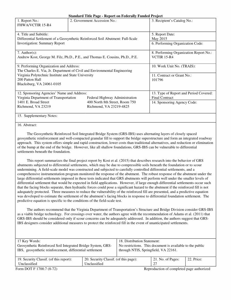
Standard Title Page - Report on Federally Funded Project
1. Report No.: 2. Government Accession No.: 3. Recipient’s Catalog No.:
FHWA/VCTIR 15-R4
4. Title and Subtitle: 5. Report Date:
Differential Settlement of a Geosynthetic Reinforced Soil Abutment: Full-Scale
Investigation: Summary Report
May 2015
6. Performing Organization Code:
7. Author(s):
Andrew Kost, George M. Filz, Ph.D., P.E., and Thomas E. Cousins, Ph.D., P.E.
8. Performing Organization Report No.:
VCTIR 15-R4
9. Performing Organization and Address:
The Charles E. Via, Jr. Department of Civil and Environmental Engineering
Virginia Polytechnic Institute and State University
200 Patton Hall
Blacksburg, VA 24061-0105
10. Work Unit No. (TRAIS):
11. Contract or Grant No.:
101796
12. Sponsoring Agencies’ Name and Address: 13. Type of Report and Period Covered:
Virginia Department of Transportation
1401 E. Broad Street
Richmond, VA 23219
Federal Highway Administration
400 North 8th Street, Room 750
Richmond, VA 23219-4825
Final Contract
14. Sponsoring Agency Code:
15. Supplementary Notes:
16. Abstract:
The Geosynthetic Reinforced Soil Integrated Bridge System (GRS-IBS) uses alternating layers of closely spaced
geosynthetic reinforcement and well-compacted granular fill to support the bridge superstructure and form an integrated roadway
approach. This system offers simple and rapid construction, lower costs than traditional alternatives, and reduction or elimination
of the bump at the end of the bridge. However, like all shallow foundations, GRS-IBS can be vulnerable to differential
settlements beneath the foundation.
This report summarizes the final project report by Kost et al. (2015) that describes research into the behavior of GRS
abutments subjected to differential settlements, which may be due to compressible soils beneath the foundation or to scour
undermining. A field-scale model was constructed and subjected to carefully controlled differential settlements, and a
comprehensive instrumentation program monitored the response of the abutment. The robust response of the abutment under the
large differential settlements imposed in these tests indicated that GRS abutments will perform well under the smaller levels of
differential settlement that would be expected in field applications. However, if large enough differential settlements occur such
that the facing blocks separate, then hydraulic forces could pose a significant hazard to the abutment if the reinforced fill is not
adequately protected. Three measures to reduce the vulnerability of the reinforced fill are presented, and a predictive equation
was developed to estimate the settlement of the abutment’s facing blocks in response to differential foundation settlement. The
predictive equation is specific to the conditions of the field-scale test.
The authors recommend that the Virginia Department of Transportation’s Structure and Bridge Division consider GRS-IBS
as a viable bridge technology. For crossings over water, the authors agree with the recommendation of Adams et al. (2011) that
GRS-IBS should be considered only if scour concerns can be adequately addressed. In addition, the authors suggest that GRS-
IBS designers consider additional measures to protect the reinforced fill in the event of unanticipated settlements.
17 Key Words: 18. Distribution Statement:
Geosynthetic Reinforced Soil Integrated Bridge System, GRS-
IBS, geosynthetic reinforcement, differential settlement
No restrictions. This document is available to the public
through NTIS, Springfield, VA 22161.
19. Security Classif. (of this report): 20. Security Classif. (of this page): 21. No. of Pages: 22. Price:
Unclassified Unclassified 27
Form DOT F 1700.7 (8-72) Reproduction of completed page authorized
FINAL REPORT
DIFFERENTIAL SETTLEMENT OF A GEOSYNTHETIC REINFORCED SOIL
ABUTMENT: FULL-SCALE INVESTIGATION:
SUMMARY REPORT
Andrew Kost, E.I.
Graduate Student
George M. Filz, Ph.D., P.E.
Professor
Thomas E. Cousins, Ph.D., P.E.
Professor
The Charles E. Via, Jr. Department of Civil and Environmental Engineering
Virginia Tech
VCTIR Project Manager
Michael C. Brown, Ph.D., P.E., Virginia Center for Transportation Innovation and Research
In Cooperation with the U.S. Department of Transportation
Federal Highway Administration
Virginia Center for Transportation Innovation and Research
(A partnership of the Virginia Department of Transportation
and the University of Virginia since 1948)
Charlottesville, Virginia
May 2015
VCTIR 15-R4
ii
DISCLAIMER
The project that is the subject of this report was done under contract for the Virginia
Department of Transportation, Virginia Center for Transportation Innovation and Research. The
contents of this report reflect the views of the authors, who are responsible for the facts and the
accuracy of the data presented herein. The contents do not necessarily reflect the official views
or policies of the Virginia Department of Transportation, the Commonwealth Transportation
Board, or the Federal Highway Administration. This report does not constitute a standard,
specification, or regulation. Any inclusion of manufacturer names, trade names, or trademarks is
for identification purposes only and is not to be considered an endorsement.
Each contract report is peer reviewed and accepted for publication by staff of Virginia
Center for Transportation Innovation and Research with expertise in related technical areas.
Final editing and proofreading of the report are performed by the contractor.
Copyright 2015 by the Commonwealth of Virginia.
All rights reserved.
iii
ABSTRACT
The Geosynthetic Reinforced Soil Integrated Bridge System (GRS-IBS) uses alternating
layers of closely spaced geosynthetic reinforcement and well-compacted granular fill to support
the bridge superstructure and form an integrated roadway approach. This system offers simple
and rapid construction, lower costs than traditional alternatives, and reduction or elimination of
the bump at the end of the bridge. However, like all shallow foundations, GRS-IBS can be
vulnerable to differential settlements beneath the foundation.
This report summarizes the final project report by Kost et al. (2015) that describes
research into the behavior of GRS abutments subjected to differential settlements, which may be
due to compressible soils beneath the foundation or to scour undermining. A field-scale model
was constructed and subjected to carefully controlled differential settlements, and a
comprehensive instrumentation program monitored the response of the abutment. The robust
response of the abutment under the large differential settlements imposed in these tests indicated
that GRS abutments will perform well under the smaller levels of differential settlement that
would be expected in field applications. However, if large enough differential settlements occur
such that the facing blocks separate, then hydraulic forces could pose a significant hazard to the
abutment unless the reinforced fill is adequately protected. Three measures to reduce the
vulnerability of the reinforced fill are presented, and a predictive equation was developed to
estimate the settlement of the abutment’s facing blocks in response to differential foundation
settlement. The predictive equation is specific to the conditions of the field-scale test.
The authors recommend that the Virginia Department of Transportation’s Structure and
Bridge Division consider GRS-IBS as a viable bridge technology. For crossings over water, the
authors agree with the recommendation of Adams et al. (2011) that GRS-IBS should be
considered only if scour concerns can be adequately addressed. In addition, the authors suggest
that GRS-IBS designers consider additional measures to protect the reinforced fill in the event of
unanticipated settlements.
1
FINAL REPORT
DIFFERENTIAL SETTLEMENT OF A GEOSYNTHETIC REINFORCED SOIL
ABUTMENT: FULL-SCALE INVESTIGATION:
SUMMARY REPORT
Andrew Kost, E.I.
Graduate Student
George M. Filz, Ph.D., P.E.
Professor
Thomas E. Cousins, Ph.D., P.E.
Professor
The Charles E. Via, Jr. Department of Civil and Environmental Engineering
Virginia Tech
INTRODUCTION
Geosynthetic reinforced soil (GRS) consists of alternating layers of well-compacted
granular fill and closely spaced geosynthetic reinforcement. While GRS systems share many
similarities with more familiar mechanically stabilized earth (MSE) systems, proponents of GRS
highlight differences between the two systems and provide separate guidelines for design and
construction of GRS systems. In particular, Adams et al. (2011) emphasize: (1) composite action
of the compacted fill and closely spaced geosynthetic reinforcement layers in GRS systems and
(2) frictional connections between the reinforcement and facing elements in GRS walls versus
structural connections between the reinforcement and facing elements in most MSE walls.
GRS systems have been utilized in retaining structures since the 1970s. More recently,
researchers at the Federal Highway Administration (FHWA) (Adams et al., 1999), the Colorado
Department of Transportation (Abu-Hejleh et al., 2002), and the University of Colorado (Wu et
al., 2006) have explored applications for bridge abutments. The result has been the development
of the GRS Integrated Bridge System, or GRS-IBS. The system consists of a reinforced soil
foundation (RSF), a GRS abutment, and an integrated approach (Adams et al., 2011). The bridge
superstructure is supported directly on the reinforced soil abutment, without utilizing any deep
foundations.
GRS-IBS technology offers a number of advantages over traditional pile-supported
bridges, including lower cost, simple and rapid construction, and reduced environmental impact
(Adams et al., 2011). The abutment supports both the superstructure and approach and allows
these two components to settle uniformly, reducing or eliminating the bump that often forms at
the end of the bridge. However, the absence of deep foundations has contributed to a perceived
vulnerability of the system to changes in the support condition at the foundation level.
Differential settlements have the potential to negatively impact any type of shallow foundation,
2
including GRS abutments. In particular, because many GRS-IBS bridges are placed along
waterways, the possibility of scour-induced settlement must be considered.
While reinforced soil structures are widely considered to possess inherent flexibility, the
authors are not aware of any research examining the behavior of a load-bearing GRS structure
subjected to variable support conditions at its base. Like all shallow foundations, GRS-IBS
structures are designed with the assumption that the structure will not experience detrimental
differential settlements. The designer will conduct subsurface explorations, require excavation
and replacement of soft soils beneath the RSF, and provide compaction specifications for the
subgrade beneath the RSF in an effort to minimize settlements due to compressible soils beneath
the foundation (Adams et al., 2011). Likewise, the designer will assess hydraulic flow, scour
potential, and channel instability; place the top of the RSF beneath the calculated scour depth;
and employ scour countermeasures as appropriate, to guard against scour-induced settlements
(Adams et al., 2011). However, it is helpful for both the designer and the owner to understand
the potential consequences for the structure if these measures fall short. Additionally,
investigating the response of GRS abutments subjected to large differential settlements provides
unique insight into their behavior that could not be gained from observations of the structures
under normal operating conditions.
PURPOSE AND SCOPE
This project began as a collaboration between the Virginia Department of Transportation
(VDOT) and Virginia Tech to provide design support and monitoring for the first GRS-IBS
bridge in Virginia. A crossing along Towlston Road near McLean, Virginia, was selected for the
pilot project. However, a number of extenuating circumstances, including the washout of the
existing structure in September 2011, contributed to significant delays for the project. When it
became evident that much of the original scope of work would occur outside of the schedule for
this project, Virginia Tech proposed modifications to the scope to examine the effects of
differential settlements on GRS-IBS structures.
The purpose of this research was to address a lack of knowledge regarding the
performance of GRS-IBS in response to differential settlements, whether these settlements result
from the presence of compressible soils beneath the foundation or are due to scour of the
subgrade material. This knowledge will help policy-makers, owners, and designers make
informed decisions regarding implementation of GRS systems. To this end, a field-scale
investigation was carried out at Virginia Tech. The field-scale experiment examined the
response of one GRS abutment to differential settlements represented by two different areas and
two different depths, for a total of four support-loss conditions. Because the field-scale model
lacked an integrated approach, the term “GRS abutments” is used in place of “GRS-IBS”
throughout this report when referring to observations specific to the experimental abutment.
However, the experimental GRS abutment did include a reinforced soil foundation, a load-
bearing GRS wall, and an equivalent bridge load, so the test was representative of a GRS-IBS
installation in most respects.
Nine project tasks were established:
3
1. Develop a test concept to induce carefully controlled settlements beneath a field-scale
GRS abutment.
2. Design the field-scale model to adequately represent an in-service abutment while
ensuring measurable abutment response and remaining within the constraints of the
testing site.
3. Select materials that are representative of materials commonly used for GRS-IBS.
4. Construct the field-scale abutment using techniques and methods representative of
typical GRS-IBS construction.
5. Instrument the abutment to observe key indicators of structural response during
testing, including settlement of the fill and facing blocks, stress changes within the
reinforced fill, and strain changes in the reinforcement.
6. Subject the abutment to differential settlements of carefully controlled magnitude and
area, and measure the abutment’s response.
7. Reduce and interpret data collected during testing, identifying important trends and
behavior of the abutment.
8. Develop a predictive equation to estimate the settlement of the abutment as a function
of area of support removed, depth of support removed, and height above the
foundation.
9. Develop conclusions and recommendations for VDOT regarding the implementation
of GRS-IBS based on the results of this study and the authors’ experience in
designing and constructing the test abutment, and provide recommendations for
future research.
This report summarizes the results of these project tasks. Complete details of this project,
particularly with regard to the methods, results, and discussion, are provided in the final project
report (Kost et al., 2015). Design and construction procedures (Tasks 1-4) are summarized in the
“Methods” section. The extensive instrumentation effort (Task 5) and testing procedures (Task
6) are also summarized in the “Methods” section. Data were collected during testing and
reduced. The key conclusions are presented along with the predictive equation in the “Results
and Discussion” section (Tasks 7 and 8). The “Conclusions” and “Recommendations” sections
(Task 9) follow, and the report concludes with “Benefits and Implementation Prospects.”
METHODS
A field-scale testing program was carried out to investigate the response of GRS
abutments to differential settlements. The following sections summarize the experimental
concept and design, materials, testing site, construction, instrumentation, and testing procedures.
4
Experimental Concept
A method of simulating settlement beneath a column-supported embankment using
geofoam was developed by Sloan et al. (2013). This method was modified to simulate
differential settlements beneath a GRS abutment. A field-scale abutment was constructed over a
subgrade in which the support conditions were carefully controlled. The primary subgrade
material was a well-compacted crushed rock fill. However, in regions where differential
settlements would be induced, a portion of the crushed rock was replaced with a stiff, expanded
polystyrene (EPS, commonly referred to as geofoam) inclusion. This foam was stiff enough to
support the abutment without excessive deformations, and it could later be dissolved using an
environmentally friendly solvent to simulate settlement in these regions.
Experimental Design
Thorough consideration was given to appropriate dimensioning of the experimental
abutment and the regions from which support would be removed. The objectives throughout the
design process were to model a reasonable abutment geometry, to ensure that settlements
induced at the foundation level would be large enough to produce measureable deformations at
the surface, and to minimize the influence of tests at one corner of the abutment on results
observed at the opposite corner. This section details the design of the abutment and reinforced
soil foundation, the location of the geofoam inclusions, and a protective wrap that was included
behind the facing elements at one level of the abutment.
Abutment and Reinforced Soil Foundation
The test abutment, including its reinforced soil foundation (RSF), was designed and
detailed in accordance with FHWA guidelines (Adams et al., 2011). This design procedure is
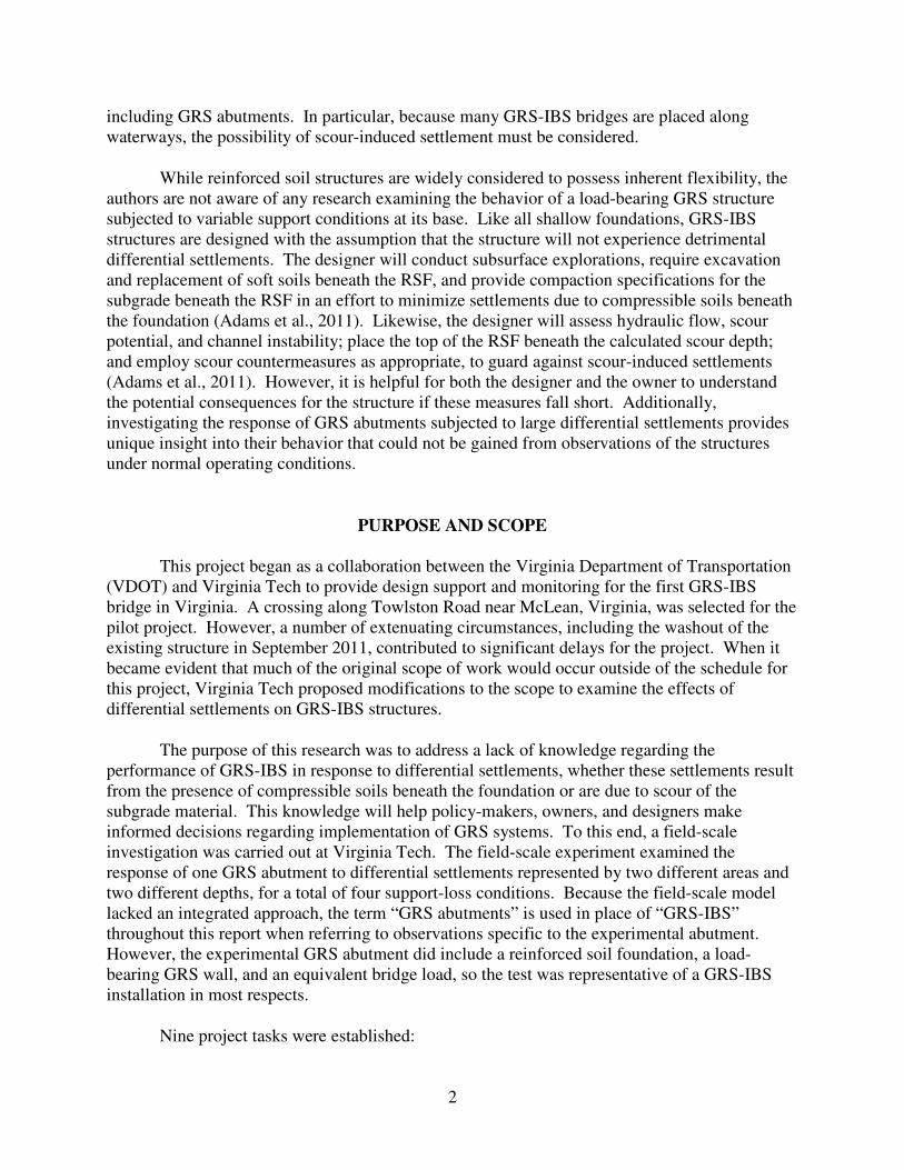
most reflective of the current state of the practice. Figure 1 shows a front view of the abutment
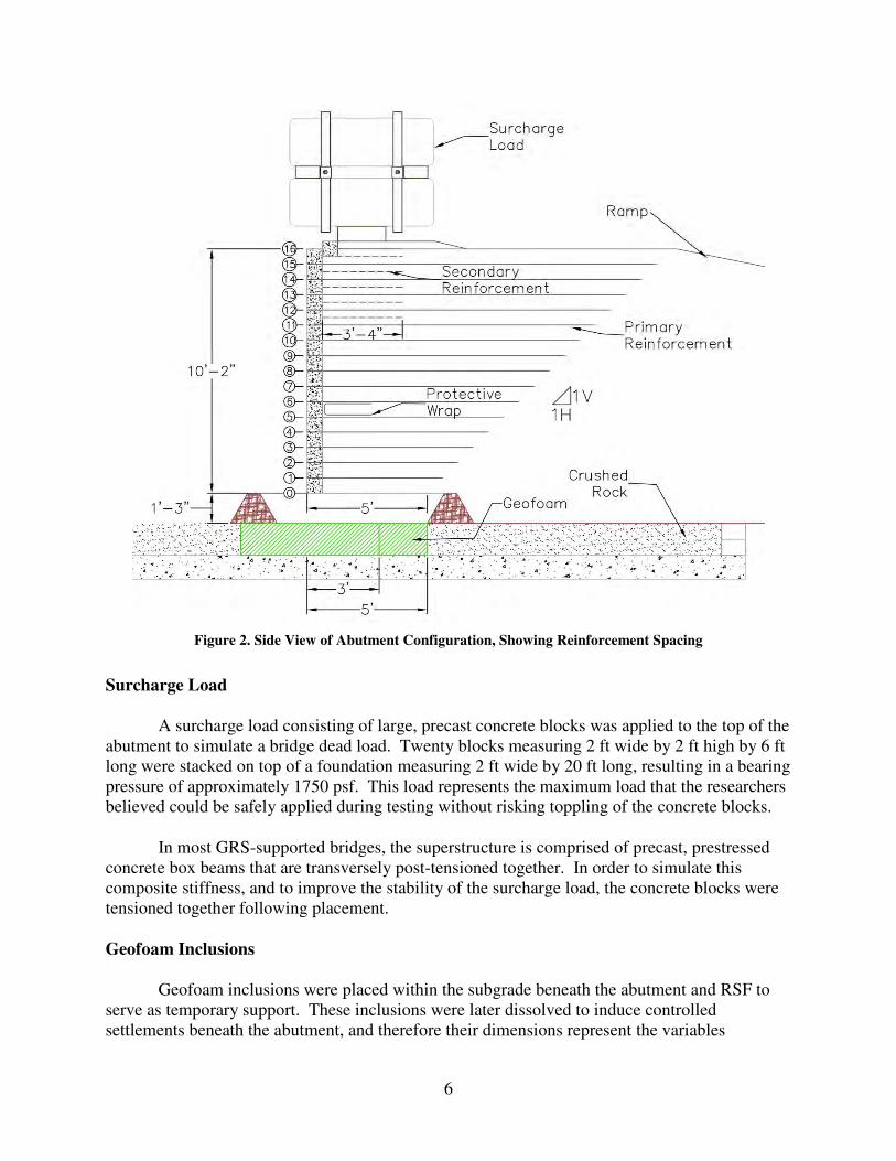
configuration with the relevant dimensions marked, and Figure 2 shows a side view of the
abutment with the internal reinforcement layout. Consistent with the terminology used in the
FHWA guidelines, this report will use the term “length” to refer to the abutment dimension in
the horizontal plane of the abutment face, transverse to a non-skewed bridge alignment. The
term “width” will refer to the abutment dimension in the horizontal plane of the wing walls,
parallel to a non-skewed bridge alignment. The overall dimensions of the abutment, about 10 ft
high by 24.5 ft long, represent a geometry that is reasonable for a relatively small full-scale
bridge—for example, a one-lane bridge over a small to moderately sized stream.
When possible, the most critical case was selected in designing the abutment. For
example, the base width of the abutment was set to 5 ft, the minimum allowed by the FHWA
guidelines for small spans. However, many of the dimensions were also constrained by the
testing location. For example, the length of the abutment was limited by the size of the concrete
mat foundation. The height was limited both by site constraints and by the need to ensure
surface expression of the differential settlements at the base (i.e., measureable deformations at
the surface of the abutment).
5
Figure 1. Front View of Abutment Configuration
The width of the abutment increased at a constant 1H:1V slope over the entire height of
the abutment. Because the base of the abutment was placed above the surrounding grade, a ramp
of compacted, crushed rock was placed as construction progressed to support the abutment at this
1H:1V slope. This ramp also served to simulate the cut or fill slope behind the abutment, to
apply representative horizontal earth pressures to the back of the abutment, and to permit
delivery of materials to the top of the abutment throughout construction.
Primary reinforcement was spaced at 8-in vertical intervals throughout the abutment.
Secondary reinforcement was placed in the upper five levels at the midpoint of primary
reinforcement, resulting in a combined spacing of 4 in for the primary and secondary
reinforcement, as shown in Figure 2. The secondary spacing and bearing bed for the surcharge
load were detailed in accordance with FHWA guidelines, although some non-structural detailing
was omitted. The integrated approach was also omitted from the test abutment.
The RSF extended a minimum of 0.25 times the base width, or 15 in, from the abutment
at the face and both wing walls and was 15 in deep. Adams et al. (2011) indicate that
reinforcement is commonly spaced at 12 in within the RSF. In order not to exceed this
recommendation, one sheet of primary reinforcement was placed within the RSF at a distance of
7.5 in from the bottom and top of the RSF.
6
Figure 2. Side View of Abutment Configuration, Showing Reinforcement Spacing
Surcharge Load
A surcharge load consisting of large, precast concrete blocks was applied to the top of the
abutment to simulate a bridge dead load. Twenty blocks measuring 2 ft wide by 2 ft high by 6 ft
long were stacked on top of a foundation measuring 2 ft wide by 20 ft long, resulting in a bearing
pressure of approximately 1750 psf. This load represents the maximum load that the researchers
believed could be safely applied during testing without risking toppling of the concrete blocks.
In most GRS-supported bridges, the superstructure is comprised of precast, prestressed
concrete box beams that are transversely post-tensioned together. In order to simulate this
composite stiffness, and to improve the stability of the surcharge load, the concrete blocks were
tensioned together following placement.
Geofoam Inclusions
Geofoam inclusions were placed within the subgrade beneath the abutment and RSF to
serve as temporary support. These inclusions were later dissolved to induce controlled
settlements beneath the abutment, and therefore their dimensions represent the variables
7
investigated in this research. Consequently, considerable care was taken in selecting the
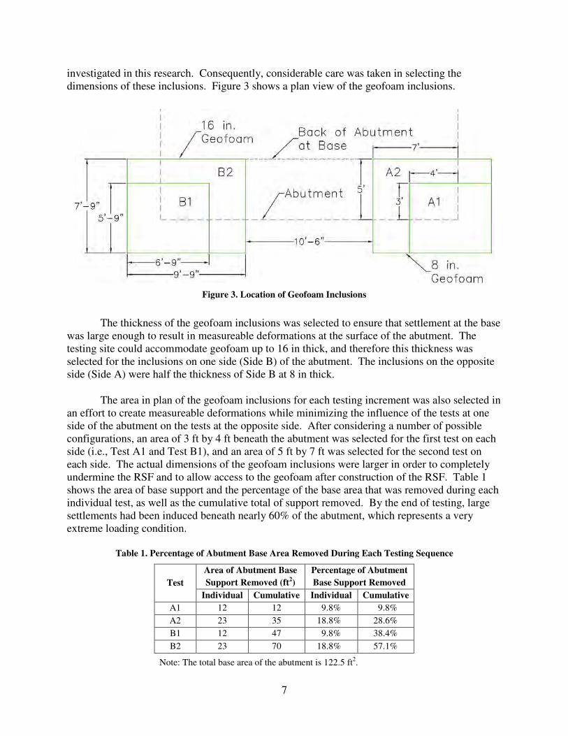
dimensions of these inclusions. Figure 3 shows a plan view of the geofoam inclusions.
Figure 3. Location of Geofoam Inclusions
The thickness of the geofoam inclusions was selected to ensure that settlement at the base
was large enough to result in measureable deformations at the surface of the abutment. The
testing site could accommodate geofoam up to 16 in thick, and therefore this thickness was
selected for the inclusions on one side (Side B) of the abutment. The inclusions on the opposite
side (Side A) were half the thickness of Side B at 8 in thick.
The area in plan of the geofoam inclusions for each testing increment was also selected in
an effort to create measureable deformations while minimizing the influence of the tests at one
side of the abutment on the tests at the opposite side. After considering a number of possible
configurations, an area of 3 ft by 4 ft beneath the abutment was selected for the first test on each
side (i.e., Test A1 and Test B1), and an area of 5 ft by 7 ft was selected for the second test on
each side. The actual dimensions of the geofoam inclusions were larger in order to completely
undermine the RSF and to allow access to the geofoam after construction of the RSF. Table 1
shows the area of base support and the percentage of the base area that was removed during each
individual test, as well as the cumulative total of support removed. By the end of testing, large
settlements had been induced beneath nearly 60% of the abutment, which represents a very
extreme loading condition.
Table 1. Percentage of Abutment Base Area Removed During Each Testing Sequence
Test
Area of Abutment Base
Support Removed (ft2)
Percentage of Abutment
Base Support Removed
Individual Cumulative Individual Cumulative
A1 12 12 9.8% 9.8%
A2 23 35 18.8% 28.6%
B1 12 47 9.8% 38.4%
B2 23 70 18.8% 57.1%
Note: The total base area of the abutment is 122.5 ft2.
8
Protective Wrap
During the experiment’s design, a suggestion was provided to the researchers by Andy
Zickler of VDOT to explore the effectiveness of a wrap behind the facing units to prevent
erosion of the backfill material in case gaps were to form between the facing units. The
researchers incorporated this suggestion at one level of the abutment, Level 6, as shown in
Figure 2. The wrap was designed to be one continuous length behind the abutment face and both
wing walls. A 7.5-ft-wide roll of fabric was used for the wrap, resulting in an embedded length
of approximately 3 ft 4 in.
In deciding to incorporate this suggestion, the researchers considered that including
additional reinforcement at this level may alter the stiffness of the reinforced fill and therefore
influence the stress distribution within the reinforced fill. The geotextile selected for this
application was very lightweight in order to minimize this effect, and unnecessary material
where the geotextile was folded at the corners of the abutment was removed. The researchers
were also concerned that the interface friction angle between the two geotextiles may be less
than the interface friction angle between the primary reinforcement and the fill. Consequently, a
very thin layer of aggregate was placed between the two geotextiles. The procedure for
installing this protective wrap is further described later in this report.
Materials
This section summarizes the materials that were used in the construction and testing of
the GRS abutment. Materials were selected that are typical of in-service GRS-IBS bridges.
Fill
A crushed rock fill is the primary structural component of a GRS system. The FHWA
guidelines allow for use of either a well-graded fill or an open-graded fill. To date, the vast
majority of GRS-IBS projects have used an open-graded fill, and therefore an open-graded fill
(ASTM No. 8) was also selected for this project. The No. 8 fill has a maximum particle size of
0.5 in and less than 5% passing the No. 16 sieve.
A well-graded fill must be used for the RSF. For this project, the VDOT No. 21A crushed
rock, which has a maximum particle size of 2 in and a fines content between 6% and 12%, was
selected for the RSF.
Geotextiles
Two geotextiles were used in the construction of the abutment. The geotextile used for
fill reinforcement was a TenCate Mirafi HP570, which is a biaxial, woven polypropylene
geotextile having an ultimate tensile strength of 4,800 lb/ft. The HP570 was used for both the
primary and secondary layers of reinforcement in the abutment, and also for the RSF.
The second geotextile was used to create the protective wrap behind the Level 6 facing
units. The Tencate Mirafi 140N, a very lightweight geotextile for filtration applications, was
9
selected for this application. The 140N is a needlepunched, non-woven geotextile with an
apparent opening size (AOS) of 0.212 mm and a permittivity of 1.7 sec-1
, according to the
manufacturer.
Facing Units
This project used nominal 8 in by 8 in by 16 in hollow-core concrete masonry units
(CMUs) with a compressive strength of 4,000 psi. The project duration was less than six months
and occurred in the summer and fall; therefore, resistance to freeze-thaw cycles was not
considered.
Geofoam
An Insulfoam EPS39 geofoam was selected for the geofoam inclusions beneath the
abutment. In general, geofoam should have a large enough stiffness to ensure that its strain does
not exceed 1%, or creep behavior may result. According to the manufacturer, the EPS39
experiences 1% strain at a compressive stress of 15 psi, which is considerably higher than the
estimated 11.6 psi of stress applied to the subgrade.
Geonet
A geonet was used as part of the solvent delivery system to evenly distribute the solvent
beneath the geofoam inclusions. The geonet used for this project was a SynTec UBXC, which
has a thickness of 200 mils and a transmissivity of 2 x 10⁻³
m2/s in the machine direction,
according to the manufacturer.
Solvent
Expanded polystyrene (EPS) can be readily dissolved using a variety of agents. For this
project, a biodegradable, non-caustic solvent known as d-Limonene was used. d-Limonene is
derived from concentration of citric oils and is commonly used in the recycling industry to
reduce the volume of EPS packaging.
Testing Site
The abutment was constructed at Virginia Tech’s Kentland Farm, located about 10 miles
west of the Blacksburg campus. At the farm, the researchers have access to a 30-ft-square, 12-
in-thick concrete mat foundation. The mat is enclosed by a 16-in-high CMU wall, with the top
of the wall at grade with the adjacent ground surface. The mat provides a stable foundation for
the abutment and ensures that measured deformations are the result of the induced differential
settlements rather than consolidation of the underlying natural soils.
Construction
Construction of the test abutment utilized a crew of two or three students who did not
have prior experience with GRS construction. Even so, the crew found that they were able to
10
carry out the construction operation without undue difficulty. Construction equipment was
generally small and hand-operated. A small Bobcat utility vehicle was also used to move fill and
other materials during construction.
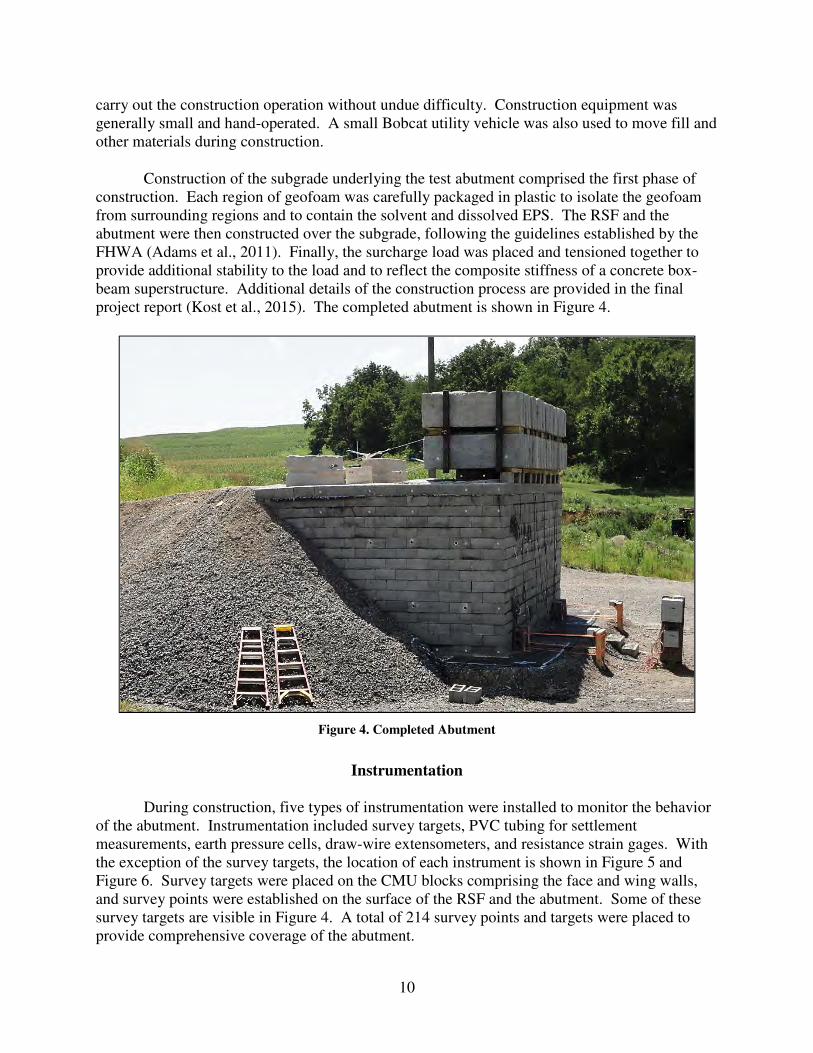
Construction of the subgrade underlying the test abutment comprised the first phase of
construction. Each region of geofoam was carefully packaged in plastic to isolate the geofoam
from surrounding regions and to contain the solvent and dissolved EPS. The RSF and the
abutment were then constructed over the subgrade, following the guidelines established by the
FHWA (Adams et al., 2011). Finally, the surcharge load was placed and tensioned together to
provide additional stability to the load and to reflect the composite stiffness of a concrete box-
beam superstructure. Additional details of the construction process are provided in the final
project report (Kost et al., 2015). The completed abutment is shown in Figure 4.
Figure 4. Completed Abutment
Instrumentation
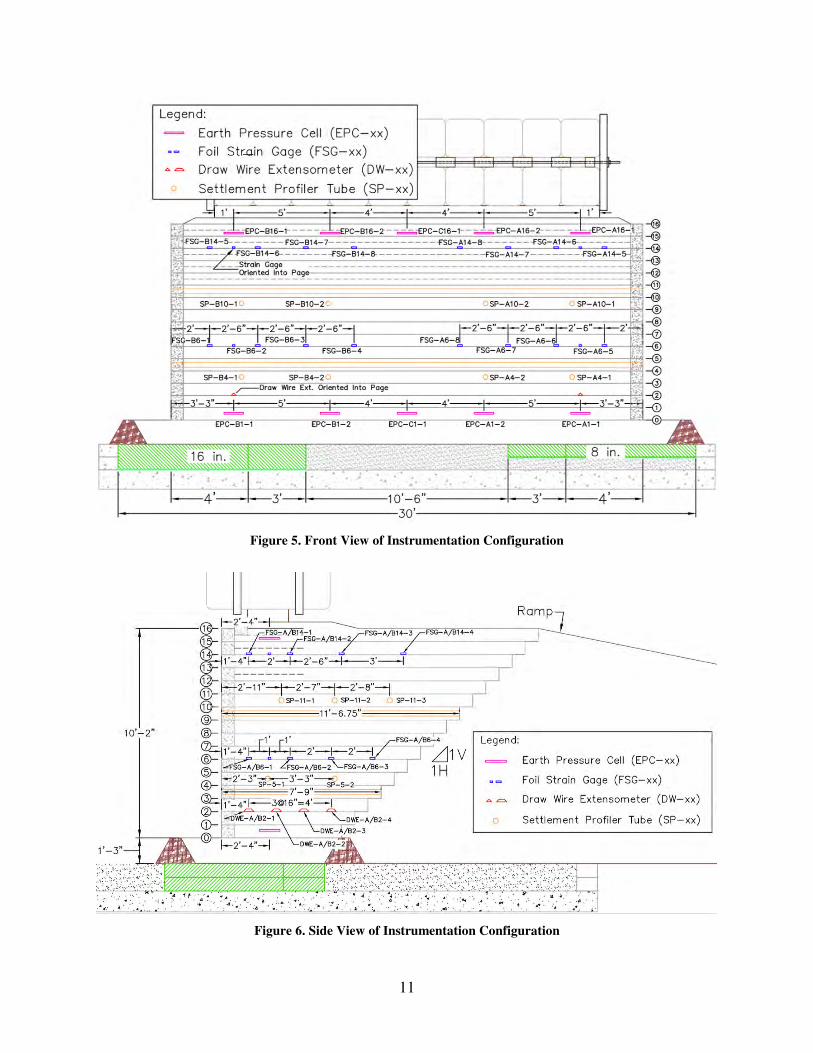
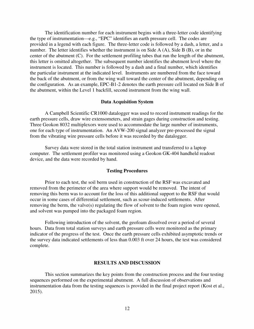
During construction, five types of instrumentation were installed to monitor the behavior
of the abutment. Instrumentation included survey targets, PVC tubing for settlement
measurements, earth pressure cells, draw-wire extensometers, and resistance strain gages. With
the exception of the survey targets, the location of each instrument is shown in Figure 5 and
Figure 6. Survey targets were placed on the CMU blocks comprising the face and wing walls,
and survey points were established on the surface of the RSF and the abutment. Some of these
survey targets are visible in Figure 4. A total of 214 survey points and targets were placed to
provide comprehensive coverage of the abutment.
11
Figure 5. Front View of Instrumentation Configuration
Figure 6. Side View of Instrumentation Configuration
12
The identification number for each instrument begins with a three-letter code identifying
the type of instrumentation—e.g., “EPC” identifies an earth pressure cell. The codes are
provided in a legend with each figure. The three-letter code is followed by a dash, a letter, and a
number. The letter identifies whether the instrument is on Side A (A), Side B (B), or in the
center of the abutment (C). For the settlement profiling tubes that run the length of the abutment,
this letter is omitted altogether. The subsequent number identifies the abutment level where the
instrument is located. This number is followed by a dash and a final number, which identifies
the particular instrument at the indicated level. Instruments are numbered from the face toward
the back of the abutment, or from the wing wall toward the center of the abutment, depending on
the configuration. As an example, EPC-B1-2 denotes the earth pressure cell located on Side B of
the abutment, within the Level 1 backfill, second instrument from the wing wall.
Data Acquisition System
A Campbell Scientific CR1000 datalogger was used to record instrument readings for the
earth pressure cells, draw wire extensometers, and strain gages during construction and testing.
Three Geokon 8032 multiplexors were used to accommodate the large number of instruments,
one for each type of instrumentation. An AVW-200 signal analyzer pre-processed the signal
from the vibrating wire pressure cells before it was recorded by the datalogger.
Survey data were stored in the total station instrument and transferred to a laptop
computer. The settlement profiler was monitored using a Geokon GK-404 handheld readout
device, and the data were recorded by hand.
Testing Procedures
Prior to each test, the soil berm used in construction of the RSF was excavated and
removed from the perimeter of the area where support would be removed. The intent of
removing this berm was to account for the loss of this additional support to the RSF that would
occur in some cases of differential settlement, such as scour-induced settlements. After
removing the berm, the valve(s) regulating the flow of solvent to the foam region were opened,
and solvent was pumped into the packaged foam region.
Following introduction of the solvent, the geofoam dissolved over a period of several
hours. Data from total station surveys and earth pressure cells were monitored as the primary
indicator of the progress of the test. Once the earth pressure cells exhibited asymptotic trends or
the survey data indicated settlements of less than 0.003 ft over 24 hours, the test was considered
complete.
RESULTS AND DISCUSSION
This section summarizes the key points from the construction process and the four testing
sequences performed on the experimental abutment. A full discussion of observations and
instrumentation data from the testing sequences is provided in the final project report (Kost et al.,
2015).
13
General construction and testing observations are presented, and the most important
observations from the instrumentation data are summarized. Next, based on the observations of
abutment performance, three potential methods of mitigating the vulnerability of the reinforced
fill are presented. A discussion of the authors’ investigation into repair methods for the abutment
follows, and the section concludes with recommendations for future research.
Construction Observations
Although construction of the test abutment utilized a crew of two or three students who
did not have prior experience with GRS construction, the crew found that they were able to carry
out the construction operation without undue difficulty. In total, construction and
instrumentation of the abutment, including placement of the surcharge load, took 35 working
days. A photograph of the completed abutment was presented in Figure 4. Instrumentation data
were collected during construction and are discussed later in this report.
The FHWA manual by Adams et al. (2011) was consulted as the primary reference for
construction. The authors found the construction guidance in the manual to be accessible and
generally easy to reference, with a number of helpful photographs.
General Testing Observations
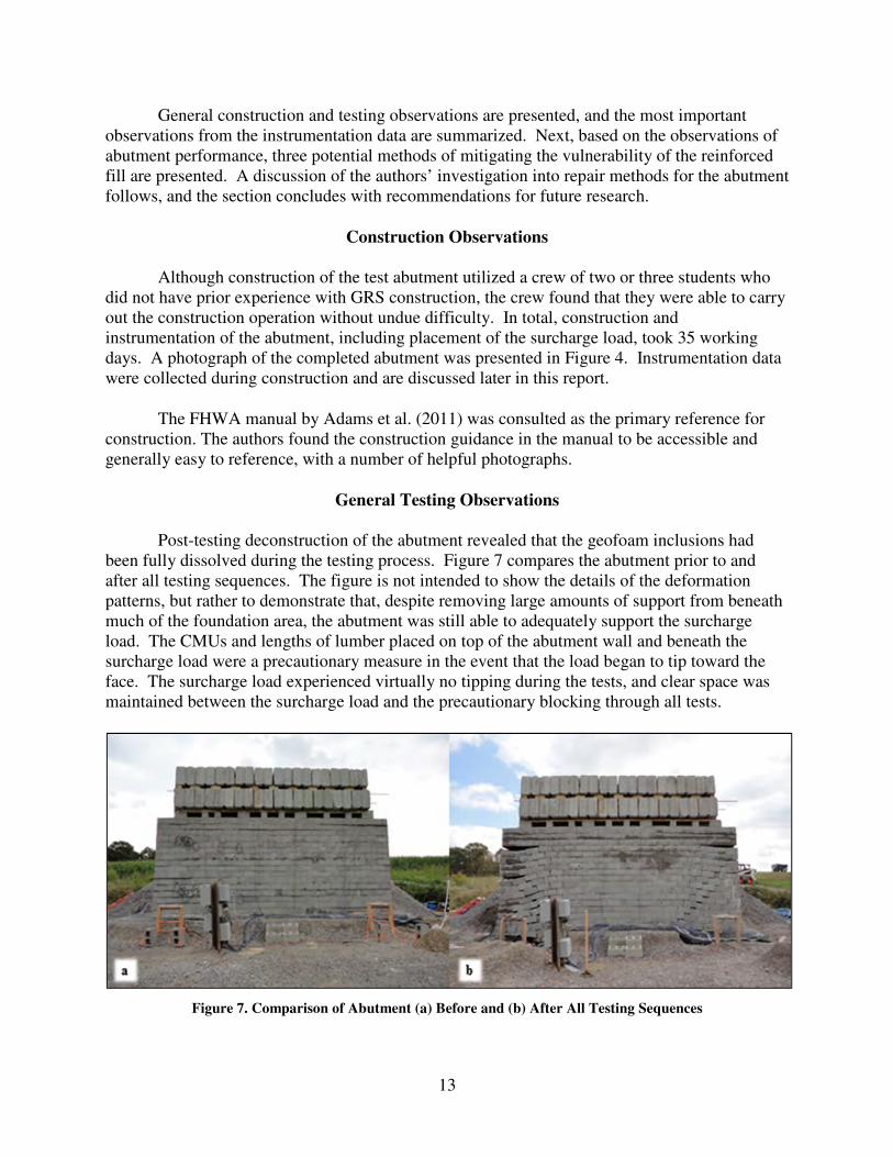
Post-testing deconstruction of the abutment revealed that the geofoam inclusions had
been fully dissolved during the testing process. Figure 7 compares the abutment prior to and
after all testing sequences. The figure is not intended to show the details of the deformation
patterns, but rather to demonstrate that, despite removing large amounts of support from beneath
much of the foundation area, the abutment was still able to adequately support the surcharge
load. The CMUs and lengths of lumber placed on top of the abutment wall and beneath the
surcharge load were a precautionary measure in the event that the load began to tip toward the
face. The surcharge load experienced virtually no tipping during the tests, and clear space was
maintained between the surcharge load and the precautionary blocking through all tests.
Figure 7. Comparison of Abutment (a) Before and (b) After All Testing Sequences
14
The deformation pattern of the facing blocks demonstrates a predictable, stair-step pattern
that begins at the edge of the region where support is removed. Particularly for smaller regions
of support removal, the CMUs are able to bridge over the region of support loss and minimize
settlements of the overlying CMUs. This pattern roughly mirrors the support condition within
the reinforced fill, which is able to support the full width of the surcharge load even after support
beneath a large portion of the foundation has been removed. On Side A, the deformation
patterns induced by Test A1 are erased by the patterns of Test A2, suggesting that the same
deformation pattern would be seen if the support of Regions A1 and A2 had been removed at one
time rather than in two steps. The behavior on Side B suggests similar trends, although the
larger magnitude of settlement increases the difficulty of predicting the settlement had Regions
B1 and B2 been removed at the same time.
The blocks at and near the corners of the abutment appeared vulnerable after
experiencing settlements. This experiment tested only the response of the abutment to
differential settlements. If water action were introduced, as would occur in a scenario of scour-
induced settlement or of heavy stream flow after large differential settlements due to foundation
compression, it is quite conceivable (and perhaps likely) that the combined effects of buoyant
and viscous water forces could remove some of these CMU blocks and expose the backfill to
erosion. This scenario could lead to serious damage or failure of the abutment. Some
considerations to mitigate this hazard are discussed later in this report.
Instrumentation Data
Important observations from each of the forms of instrumentation in the abutment are
presented in the following five sections. A full explanation of these key points is provided in the
final project report (Kost et al., 2015).
Survey Targets
A full survey of the abutment was completed before and after each testing sequence, and
survey data were also used as a reference when other instrumentation data were analyzed.
Important trends are summarized as follows.
• The surcharge load remained stable throughout all testing sequences.
• Settlements at the surface decreased with distance from the region of support loss.
• The maximum angular distortion of the surcharge load in the plane parallel to the
abutment face was 0.008, and the maximum average angular distortion between the
center and edge of the surcharge load was 0.003. Both measures are within the range
of acceptable serviceability values for simply supported spans.
• The reinforced fill significantly reduced the settlements observed at the surface
compared to the base of the abutment and provided acceptable performance for the
surcharge load.
15
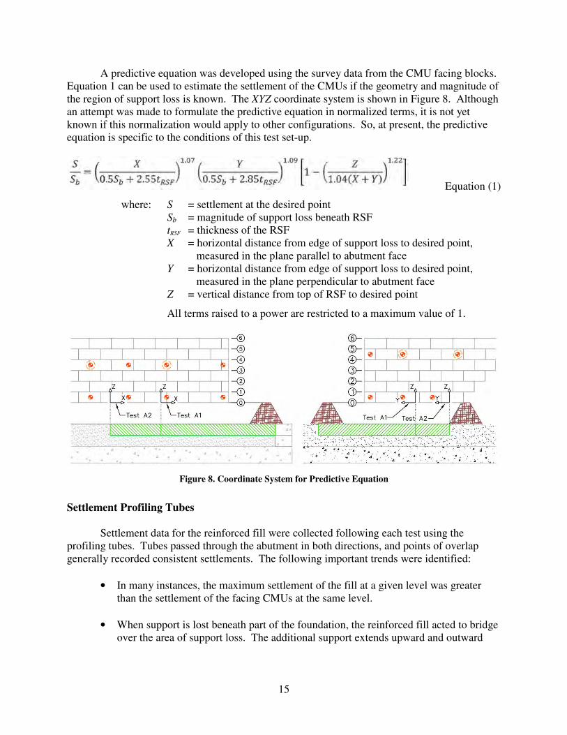
A predictive equation was developed using the survey data from the CMU facing blocks.
Equation 1 can be used to estimate the settlement of the CMUs if the geometry and magnitude of
the region of support loss is known. The XYZ coordinate system is shown in Figure 8. Although
an attempt was made to formulate the predictive equation in normalized terms, it is not yet
known if this normalization would apply to other configurations. So, at present, the predictive
equation is specific to the conditions of this test set-up.
Equation (1)
where: S = settlement at the desired point
Sb = magnitude of support loss beneath RSF
tRSF = thickness of the RSF
X = horizontal distance from edge of support loss to desired point,
measured in the plane parallel to abutment face
Y = horizontal distance from edge of support loss to desired point,
measured in the plane perpendicular to abutment face
Z = vertical distance from top of RSF to desired point
All terms raised to a power are restricted to a maximum value of 1.
Figure 8. Coordinate System for Predictive Equation
Settlement Profiling Tubes
Settlement data for the reinforced fill were collected following each test using the
profiling tubes. Tubes passed through the abutment in both directions, and points of overlap
generally recorded consistent settlements. The following important trends were identified:
• In many instances, the maximum settlement of the fill at a given level was greater
than the settlement of the facing CMUs at the same level.
• When support is lost beneath part of the foundation, the reinforced fill acted to bridge
over the area of support loss. The additional support extends upward and outward
16
from the inside edges of the region of support loss. The effect of support loss
diminishes with height above the foundation.
• Settlements within the reinforced backfill decreased and the uniformity of settlement
increased with height and with distance from the region of support loss due to the
effect of the bridging action.
• When the depth of support removal was held constant, settlement of the fill increased
with removal of the larger area of support.
• When the area of support removal was small, as in Test A1 and Test B1, the
settlements of the fill were relatively similar at the level of the profiling tubes,
independent of the depth of support removal.
• When the area of support removal was large, as in Test A2 and Test B2, the
settlement of the fill at the levels of the settlement tubes was significantly larger on
Side B than Side A, where a larger depth of support was removed on Side B.
However, surface expressions of the settlements were not necessarily larger on Side B
than Side A.
• The small settlements observed at the surface of the abutment in response to severe
differential settlement conditions at the base demonstrate robust performance in the
GRS abutment’s ability to minimize surface expressions of differential settlements
beneath its foundation.
Earth Pressure Cells
The pressure cells were monitored regularly from the time of installation through
construction and each of the four testing sequences. Pressure data could not be monitored
continuously during Test B1 due to failure of the signal analyzer for the vibrating wire
instruments. Baseline readings for the test were known, and final readings were obtained at the
end of the test once a replacement signal analyzer had been received and installed. Replacing the
signal analyzer is not believed to have impacted the zero readings of the pressure cells. The
earth pressure cells identified the following key trends:
• When support is lost beneath part of the foundation, the reinforced soil transfers load
to the portion of the foundation where the support conditions are unchanged. Vertical
stresses in the fill directly above the region of support loss drop substantially,
although this effect diminishes with increasing height above the foundation.
• Only small deformations are required to cause a re-distribution of stresses within the
reinforced fill.
• Removing a larger area of support results in more significant stress changes at upper
levels of the abutment but in similar stress changes at lower levels. The first
observation is expected to hold true for any scenario of support loss; the second
17
observation may be a function of the geometry of support removal selected for these
tests.
• For the magnitudes of foundation settlement investigated in these tests, stress changes
in the reinforced fill depend primarily on the area of support removed and not the
depth of support removed.
• Stress increases in the regions of the reinforced fill to which load is transferred imply
increased tensile demand in the reinforcement at these locations.
Draw Wire Extensometers
The draw wire extensometers at Level 2 of the abutment were monitored regularly from
the time of their installation through construction and all testing sequences. During some tests,
the displacement data were obscured by settlements of the overlying CMUs and fill, which
resulted in erroneously large displacements. Where the displacement values were not affected in
this way, the following conclusions were drawn:
• Strains observed at Level 2 during construction were small, generally less than 0.1%.
• During construction, all measured displacements showed that these strains were
directed toward the abutment face.
• Strains during Test A1 and Test B1 were small and generally resulted from
displacements toward the face.
• Strains during Test A2 were difficult to identify because large settlement of the facing
CMUs and reinforcement controlled the observed displacements; strains during Test
B2 were completely obscured by settlements of the facing CMUs.
Resistance Strain Gages
Due to multiplexor limitations, only half the gages in the abutment could be monitored at
one time. Strain gages on Side A were monitored continuously from the time of installation
through both testing sequences on Side A. Following the completion of Test A2, these gages
were disconnected, and the gages on Side B were connected and monitored through the
completion of testing. The following trends were observed:
• The maximum strain observed at Levels 6 and 14 on Side A during construction and
placement of the surcharge load was 0.8%. The maximum strain increase observed
during placement of the surcharge load alone was 0.14%.
• The FHWA procedure for calculating lateral strains due to placement of the surcharge
load gave a reasonable, if slightly conservative, estimate.
18
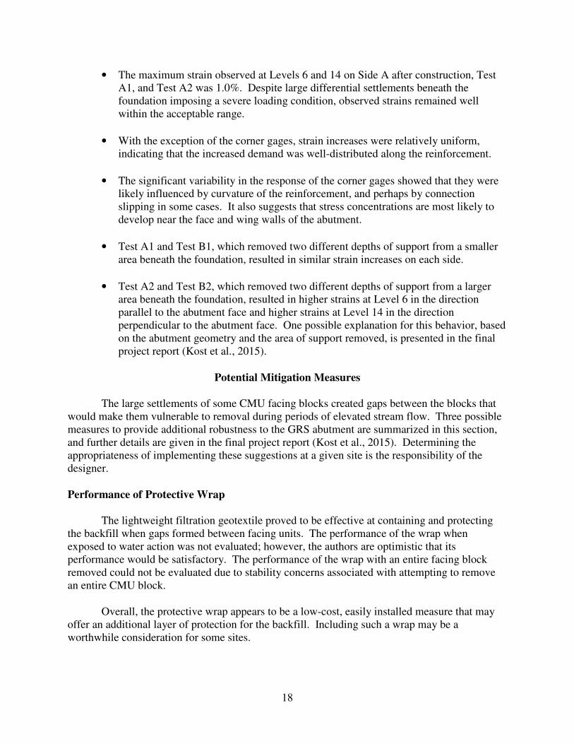
• The maximum strain observed at Levels 6 and 14 on Side A after construction, Test
A1, and Test A2 was 1.0%. Despite large differential settlements beneath the
foundation imposing a severe loading condition, observed strains remained well
within the acceptable range.
• With the exception of the corner gages, strain increases were relatively uniform,
indicating that the increased demand was well-distributed along the reinforcement.
• The significant variability in the response of the corner gages showed that they were
likely influenced by curvature of the reinforcement, and perhaps by connection
slipping in some cases. It also suggests that stress concentrations are most likely to
develop near the face and wing walls of the abutment.
• Test A1 and Test B1, which removed two different depths of support from a smaller
area beneath the foundation, resulted in similar strain increases on each side.
• Test A2 and Test B2, which removed two different depths of support from a larger
area beneath the foundation, resulted in higher strains at Level 6 in the direction
parallel to the abutment face and higher strains at Level 14 in the direction
perpendicular to the abutment face. One possible explanation for this behavior, based
on the abutment geometry and the area of support removed, is presented in the final
project report (Kost et al., 2015).
Potential Mitigation Measures
The large settlements of some CMU facing blocks created gaps between the blocks that
would make them vulnerable to removal during periods of elevated stream flow. Three possible
measures to provide additional robustness to the GRS abutment are summarized in this section,
and further details are given in the final project report (Kost et al., 2015). Determining the
appropriateness of implementing these suggestions at a given site is the responsibility of the
designer.
Performance of Protective Wrap
The lightweight filtration geotextile proved to be effective at containing and protecting
the backfill when gaps formed between facing units. The performance of the wrap when
exposed to water action was not evaluated; however, the authors are optimistic that its
performance would be satisfactory. The performance of the wrap with an entire facing block
removed could not be evaluated due to stability concerns associated with attempting to remove
an entire CMU block.
Overall, the protective wrap appears to be a low-cost, easily installed measure that may
offer an additional layer of protection for the backfill. Including such a wrap may be a
worthwhile consideration for some sites.
19
Pinning of Corner Blocks
The authors noted that the corners of the abutment appeared particularly vulnerable after
settling. One method to mitigate this exposure would be to fill the blocks near the corner with
concrete or grout and pin them together using vertical lengths of rebar, similar to way that the
upper three courses were pinned together. Adams et al. (2011) describe a similar process for
joining the wing wall and face of the abutment when the joint is not a right angle, and they note
that such a process can be used to add strength to the wall corners. Pinning these blocks together
would likely reduce the possibility of losing a facing block in the event of combined settlements
and water action. This process could also be used to reinforce the corners if impact loads are a
concern for the site. Additional details and considerations for this mitigation measure are
discussed in the final project report (Kost et al., 2015).
Increasing the Base Width of Abutment
The stability of the wall could be increased by increasing the base width of the abutment.
This measure will prevent the reinforcement from losing embedment in the case of settlements
beneath a large area of the foundation. Additionally, if this measure is combined with the
suggestion to pin the corner blocks of the abutment, the authors believe that a synergistic effect
may be observed. However, increasing the base width will also increase the overall cost of the
abutment by increasing the volume of backfill and reinforcement required to construct the
abutment, and in many cases increasing the volume of native soil that must be excavated. This
measure is expected to offer the most significant benefits to abutments that would otherwise have
a small base width, and the stability improvements it offers will likely decrease as the base width
increases.
Investigation of Repairs
Following the four testing sequences, the authors considered whether any measures could
be taken to repair the abutment. Pressure grouting was the primary method considered for
repairs. Allen Sehn at Hayward Baker, Inc. spoke with the authors over the telephone and, after
hearing a description of the problem, expressed his opinion that the likelihood of a successful
repair using this or another ground improvement method was low. The primary concern Sehn
mentioned is that the confining pressures in front of and beside the wall would not be large
enough to contain grout applied with large enough pressures to lift blocks back to an elevation
close to their original elevations.
If a GRS abutment were to experience small differential settlements that did not result in
structural distress but created gaps between the facing blocks, the authors believe that these gaps
could be patched effectively using concrete without significantly affecting the structural behavior
of the abutment. Such repairs might not be attractive.
Recommendations for Future Research
This project is, to the authors’ knowledge, the first substantial investigation into the
effects of differential settlement on GRS abutments. The large scale of the project has produced
20
a sizeable and unique data set, which presents a singular opportunity for further exploration of
this subject. The data set can allow for calibration and validation of a numerical model that can
be used to perform parametric studies and identify the influence of different abutment
geometries, different bridge loads, different areas of support loss, and different depths of support
loss. For example, the effect of support removal beneath the center of the abutment, rather than
the corners, can be investigated. The numerical model can also be used to improve upon the
predictive equation for settlement of the abutment that is presented in this report. Although the
major focus of this research was on the effect of foundation settlements beneath a GRS
abutment, much data were also obtained during GRS abutment construction and bridge loading.
Hence, the numerical model could be used to reliably perform many numerical experiments at
much lower cost than large-scale experiments. The results could then be compared with existing
analysis procedures (e.g., Adams et al., 2011) to investigate the validity of those procedures.
A protective wrap consisting of a lightweight filtration geotextile was placed behind the
facing blocks at Level 6. The purpose of this trial wrap was to examine its effectiveness in
protecting and containing the reinforced fill should gaps form between the facing blocks. While
the wrap was effective to this end, an evaluation of its performance when water action is applied
was not performed at that time. If VDOT is considering implementing this wrap in a GRS
structure that may be subjected to water action, further evaluation of its performance under these
conditions would be prudent. The effects of removing one or more facing blocks could also be
examined. This evaluation could be performed on a small GRS mass and would not constitute a
large undertaking. The authors also placed a thin layer of aggregate between the filtration
geotextile and the reinforcing geotextile to increase the interface friction angle. However, it is
possible that maintaining adequate quality control oversight of this component would be
challenging. Research could also be conducted to examine the interface friction of these two
geotextiles to determine whether the thin layer of aggregate is necessary.
CONCLUSIONS
• A testing concept was developed to induce carefully controlled differential settlements
beneath a field-scale GRS abutment. This testing concept was adapted from previous
column-supported embankment tests and used geofoam blocks as temporary support
inclusions within the subgrade, which could later be dissolved using an environmentally
friendly solvent.
• A field-scale model was designed and constructed using the FHWA manual by Adams et al.
(2011) to accurately represent an in-service abutment. The authors found the FHWA
manual to be a helpful and relatively comprehensive reference. The geometry of the
abutment, materials, and construction techniques were representative of typical GRS-IBS
construction.
• Construction of the abutment was simple and efficient. The abutment was completed in 35
working days by two or three unskilled laborers who were inexperienced with GRS
construction techniques, using a small utility vehicle and hand-operated equipment.
21
• A comprehensive instrumentation plan was designed and implemented to observe the
response of the abutment during testing.
• Differential settlements of carefully controlled magnitude and area were induced beneath the
foundation of the GRS abutment, and the abutment response was measured.
• The GRS abutment demonstrated robust behavior in response to large differential
settlements. While the large magnitude and area of settlement at the base represented an
extreme loading condition for this abutment, the settlements expressed at the surface of the
abutment were small. Stresses were redistributed within a relatively small height above the
foundation following support loss beneath the corners, maintaining support capability at
upper levels of the abutment. Strain increases in the reinforcement due to this bridging
action were not large and were generally well-distributed along the length of the
reinforcement.
• A predictive equation was developed that can be used to estimate the settlement of the facing
blocks at points over the area of support loss. The equation was calibrated using data from
the lower 11 levels (7 ft) of the abutment, and it is best-suited for use in this range. Although
an attempt was made to formulate the predictive equation in normalized terms, it is not yet
known if this normalization would apply to other configurations. So, at present, the
predictive equation is specific to the conditions of this test set-up.
• The performance of a GRS abutment is expected to be excellent when subjected to normal
levels of differential settlement due to compressible soils beneath the foundation. The robust
response of the field-scale GRS abutment to large settlements suggests excellent performance
at levels normally observed in typical applications.
• The performance of a GRS abutment may be severely compromised when exposed to scour-
induced settlements, if steps are not taken to protect the backfill from erosion. Scour-induced
settlements imply that water will also be flowing along the face of the abutment. Even after
experiencing small settlements, the facing CMUs near the corner were in a very loose
condition, and they would be susceptible to removal due to water action. The backfill would
then be exposed to erosion by the water, potentially impacting the structural integrity of the
abutment.
RECOMMENDATIONS
1. VDOT’s Structure and Bridge Division should consider GRS-IBS as a viable option for new
bridges and bridge replacements. While GRS-IBS has limitations, it is shown in this
experiment to be a robust, flexible system that can be constructed efficiently and at low cost.
2. For bridges crossing over water, VDOT’s Structure and Bridge Division should consider
GRS-IBS only if scour issues can be appropriately addressed according to the guidelines
provided by Adams et al. (2011). Placing the top of the RSF below the calculated scour
depth and/or implementing appropriate scour countermeasures are two possible means of
22
managing scour concerns. If scour cannot be addressed in a constructible and economical
manner, GRS-IBS should not be used.
3. When GRS-IBS is selected for a water crossing, VDOT’s Structure and Bridge Division
should include additional measures to protect the backfill in the event of a facing element
becoming dislodged. Three such measures considered in this study are placing a protective
wrap behind the face, joining the corner blocks with vertical lengths of rebar and grout or
concrete, and increasing the width of the base. The authors recognize that this study was not
designed to comprehensively examine these mitigation measures but are confident of their
utility after observing the performance of the test abutment.
4. VDOT’s Structure and Bridge Division should inspect in-service GRS-IBS bridges on a
regular schedule to identify and mitigate the effects of differential settlements early. GRS-
IBS bridges crossing over water should also be inspected after severe flooding events,
according to FHWA guidelines (Adams et al., 2011). If differential settlements introduce
gaps between the facing blocks that are severe enough to allow a block to be removed, the
gap should be repaired immediately. One repair measure discussed in this report is to patch
the gap with concrete.
5. VDOT’s Structure and Bridge Division should use the FHWA manual by Adams et al. (2011)
for the design and construction of GRS-IBS bridges. Until further research validates or
updates its recommendations and design procedures, this manual best represents the current
state of the practice, and it was useful to the authors in designing and constructing this
experimental abutment. For the one performance criterion that could be compared with the
values predicted by the FHWA manual—lateral strains—the FHWA procedure gave
somewhat conservative results.
6. VCTIR should consider authorizing additional research into the performance of GRS-IBS
bridges that are subjected to differential settlements. While the field-scale abutment
performed well under severe differential settlements, in many cases such settlements may
represent the greatest threat to the performance of a GRS abutment near a waterway because
of the potential for loosening the frictional connection between blocks. The data set
compiled in this field-scale experiment provides an excellent opportunity to improve
understanding of the behavior of GRS abutments by developing a numerical model, which
can be used to thoroughly investigate the influence of a range of parameters.
BENEFITS AND IMPLEMENTATION
The results of this research have validated a number of assumptions about the
performance of GRS abutments. Reinforced soil structures are generally considered to possess
inherent flexibility, but the behavior of GRS abutments, which also must support a surcharge
load, had never been rigorously examined. This research showed that the experimental GRS
abutment offered robust performance when subjected to severe differential settlements and
maintained an acceptable level of performance for the surcharge load. However, the abutment
also appeared vulnerable if scour undermining were to induce settlements of the facing blocks.
23
This understanding underscores the importance of complying with FHWA recommendations for
managing scour potential, and it allows VDOT to make informed policy and design decisions
regarding the implementation of GRS-IBS. GRS-IBS bridges can offer real cost and time
savings, and the recommendations presented in this report can be used to target the most
appropriate sites for GRS-IBS. Simple, low-cost measures to provide additional protection to
GRS abutments along waterways were introduced. Finally, a predictive equation was developed
that allows a designer to estimate the settlement of facing blocks when subjected to base
settlements of known magnitude and area.
VDOT is implementing GRS-IBS technology through construction projects in its
engineering districts, the first of which is the Towlston Road Bridge in Fairfax County.
Recommendations from this study are being incorporated by Structure and Bridge division into
designs for these structures.
ACKNOWLEDGMENTS
The authors gratefully acknowledge the organizations and individuals who contributed
funding, time, skills, and expertise to make this project successful. The funding for this project
was provided by VCTIR under the supervision of Mike Brown, and by the Via Foundation of
Virginia Tech. Mike Adams and Jennifer Nicks of FHWA and Ed Hoppe of VCTIR provided
valuable comments in the early stages of designing these experiments. Andy Zickler of VDOT
suggested a trial of the protective wrap that was included at one level of this abutment.
Jon Wooge and Dwight Paulette of Virginia Tech’s Kentland Farm allowed extended use
of the testing site at the farm and frequently offered their resources to ensure the smooth
progression of the project. Joel Sloan shared his experience conducting column-supported
embankment testing, which formed the basis of the testing methods for this experiment, and also
answered many instrumentation questions. Brett Farmer and Dennis Huffman also contributed
their extensive expertise to many aspects of the design and construction of this experiment.
Randy Dymond and the civil engineering department at Virginia Tech loaned a total station for
the duration of the field work. Bonnie Franklin’s assistance in securing materials for the
experiments was especially valuable.
Many students contributed their time to this project. Aaron Klingshirn assisted with
much of the early stages of construction and with the installation of the strain gages, and he was
instrumental in developing the Appendix of the final project report (Kost et al., 2015). Alex
Reeb, Mike Nolden, Adam Depoy, Karla Santacruz, Russ Gatermann, and Erin Murphy also
generously volunteered their time assisting with construction and taking survey data of the
abutment during testing. Brandyn Turley, Keaton Scanlan, and Matthew Amonette logged many
hours of work as undergraduate assistants, and their help was greatly appreciated.
The geotextiles used in this experiment were generously donated by TenCate thanks to
the efforts of Bruce Lacina. Herb Roy of Vishay Micro-Measurements shared his expertise in
selecting the appropriate strain gages and provided advice on installation methods. Allen Sehn
of Hayward Baker offered his time and extensive experience to discuss possible methods for
repairing the GRS abutment.
24
Many individuals from VDOT, FHWA, and other firms took a day of their time to visit
the testing site. The authors appreciated their interest and trust that it was an educational
experience for all.
Finally, the authors would like to thank the individuals who provided helpful comments
on the drafts of this report, including Mike Adams, Jennifer Nicks, Ed Hoppe, and David Shiells.
REFERENCES
Abu-Hejleh, N., Zornberg, J.C., Wang, T., and Watcharamonthein, J. Monitored Displacements
of Unique Geosynthetic-Reinforced Soil Bridge Abutments. Geosynthetics International,
Vol. 9, No. 1, 2002, pp. 71-95.
Adams, M., Ketchart, K., Ruckman, A., DiMillio, A.F., Wu, J.T.H., and Satyanarayana, R.
Reinforced Soil for Bridge Support Applications on Low-volume Roads. In
Transportation Research Record: Journal of the Transportation Research Board, No.
1652. Transportation Research Board of the National Academies, Washington, DC,
1999, pp. 150-160.
Adams, M., Nicks, J., Stabile, T., Wu, J.T.H., Schlatter, W., and Hartmann, J. Geosynthetic
Reinforced Soil Integrated Bridge System—Interim Implementation Guide. FHWA-
HRT-11-026. Federal Highway Administration, McLean, VA, 2011.
Coduto, D.P. Serviceability Requirements. In Foundation Design: Principles and Practices.
Prentice Hall, Upper Saddle River, NJ, 2001, pp. 14-46.
Kost, A., Filz, G.M., and Cousins, T.E. Differential Settlement of a Geosynthetic Reinforced Soil
Abutment: Full-Scale Investigation. VCTIR 15-R3. Virginia Center for Transportation
Innovation and Research, Charlottesville, 2015.
Sloan, J.A., Filz, G.M., and Collin, J.G. Field-Scale Column-Supported Embankment Test
Facility. Geotechnical Testing Journal, Vol. 36, No. 6, November 2013, pp. 891-902.
Wu, J.T.H., Lee, K.Z.Z., Helwany, S.M.B., and Ketchart, K. Design and Construction
Guidelines for Geosynthetic-Reinforced Soil Bridge Abutments with a Flexible Facing.
NCHRP Report No. 556. Transportation Research Board of the National Academies,
Washington, DC, 2006.