Embed Size (px)
Citation preview

1
Copyright Copperhill and Pointer, Inc., 2006 (All Rights Reserved)
Differential PressureFlow/Level Measurement
Seminar Presented by David W. Spitzer
Spitzer and Boyes, LLC+1.845.623.1830
Spitzer and Boyes, LLC (+1.845.623.1830)Copyright Copperhill and Pointer, Inc., 2006 (All Rights Reserved)
2
Copyright
This document may be viewed and printed for personal use only. No part of this document may be copied, reproduced, transmitted, or disseminated in any electronic or non-electronic format without written permission. All rights are reserved.
Copperhill and Pointer, Inc.
Spitzer and Boyes, LLC (+1.845.623.1830)Copyright Copperhill and Pointer, Inc., 2006 (All Rights Reserved)
3
Disclaimer
The information presented in this document is for the general education of the reader. Because neither the author nor the publisher have control over the use of the information by the reader, both the author and publisher disclaim any and all liability of any kind arising out of such use. The reader is expected to exercise sound professional judgment in using any of the information presented in a particular application.
Spitzer and Boyes, LLCCopperhill and Pointer, Inc.Seminar Presenter

2
Spitzer and Boyes, LLC (+1.845.623.1830)Copyright Copperhill and Pointer, Inc., 2006 (All Rights Reserved)
4
Disclaimer The full and complete contents of this document are for general information or use purposes only. The contents are provided “as is” without warranties of any kind, either expressed or implied, as to the quality, accuracy, timeliness, completeness, or fitness for a general, intended or particular purpose. No warranty or guaranty is made as to the results that may be obtained from the use of this document. The contents of this document are “works in progress” that will be revised from time to time.
Spitzer and Boyes, LLCCopperhill and Pointer, Inc.Seminar Presenter
Spitzer and Boyes, LLC (+1.845.623.1830)Copyright Copperhill and Pointer, Inc., 2006 (All Rights Reserved)
5
Disclaimer Spitzer and Boyes, LLC and Copperhill and Pointer, Inc. have no liability whatsoever for consequences of any actions resulting from or based upon information in and findings of this document. In no event, including negligence, will Spitzer and Boyes, LLC or Copperhill and Pointer, Inc. be liable for any damages whatsoever, including, without limitation, incidental, consequential, or indirect damages, or loss of business profits, arising in contract, tort or other theory from any use or inability to use this document.
Spitzer and Boyes, LLCCopperhill and Pointer, Inc.Seminar Presenter
Spitzer and Boyes, LLC (+1.845.623.1830)Copyright Copperhill and Pointer, Inc., 2006 (All Rights Reserved)
6
Disclaimer
The user of this document agrees to defend, indemnify, and hold harmless Spitzer and Boyes, LLC and Copperhill and Pointer, Inc., its employees, contractors, officers, directors and agents against all liabilities, claims and expenses, including attorney’s fees, that arise from the use of this document.
Spitzer and Boyes, LLCCopperhill and Pointer, Inc.Seminar Presenter
3
Spitzer and Boyes, LLC (+1.845.623.1830)Copyright Copperhill and Pointer, Inc., 2006 (All Rights Reserved)
7
Disclaimer
The content of this seminar was developed in an impartial manner from information provided by suppliersDiscrepancies noted and brought to the attention of the editors will be correctedWe do not endorse, favor, or disfavor any particular supplier or their equipment
Spitzer and Boyes, LLCCopperhill and Pointer, Inc.Seminar Presenter
Spitzer and Boyes, LLC (+1.845.623.1830)Copyright Copperhill and Pointer, Inc., 2006 (All Rights Reserved)
8
Seminar Outline
IntroductionFluid PropertiesDifferential Pressure FlowmetersDifferential Pressure Level TransmittersConsumer Guide
Spitzer and Boyes, LLC (+1.845.623.1830)Copyright Copperhill and Pointer, Inc., 2006 (All Rights Reserved)
9
Introduction
Working Definition of a ProcessWhy Measure Flow?

4
Spitzer and Boyes, LLC (+1.845.623.1830)Copyright Copperhill and Pointer, Inc., 2006 (All Rights Reserved)
10
Working Definition of a Process
A process is anything that changes
Spitzer and Boyes, LLC (+1.845.623.1830)Copyright Copperhill and Pointer, Inc., 2006 (All Rights Reserved)
11
Why Measure Flow and Level?
Flow and level measurements provide information about the processThe information that is needed depends on the process
Spitzer and Boyes, LLC (+1.845.623.1830)Copyright Copperhill and Pointer, Inc., 2006 (All Rights Reserved)
12
Why Measure Flow and Level?
Custody transferMeasurements are often required to determine the total quantity of:
Fluid that passed through the flowmeterMaterial present in a tank
Billing purposes

5
Spitzer and Boyes, LLC (+1.845.623.1830)Copyright Copperhill and Pointer, Inc., 2006 (All Rights Reserved)
13
Why Measure Flow and Level?
Monitor the processFlow and level measurements can be used to ensure that the process is operating satisfactorily
Spitzer and Boyes, LLC (+1.845.623.1830)Copyright Copperhill and Pointer, Inc., 2006 (All Rights Reserved)
14
Why Measure Flow and Level?
Improve the processFlow and level measurements can be used for heat and material balance calculations that can be used to improve the process
Spitzer and Boyes, LLC (+1.845.623.1830)Copyright Copperhill and Pointer, Inc., 2006 (All Rights Reserved)
15
Why Measure Flow and Level?
Monitor a safety parameterFlow and level measurements can be used to ensure that critical portions of the process operate safely
Over/under feedOver/under flow
6
Spitzer and Boyes, LLC (+1.845.623.1830)Copyright Copperhill and Pointer, Inc., 2006 (All Rights Reserved)
16
Seminar Outline
IntroductionFluid PropertiesDifferential Pressure FlowmetersDifferential Pressure Level TransmittersConsumer Guide
Spitzer and Boyes, LLC (+1.845.623.1830)Copyright Copperhill and Pointer, Inc., 2006 (All Rights Reserved)
17
Fluid Properties
TemperaturePressureDensity and Fluid ExpansionTypes of FlowInside Pipe DiameterViscosityReynolds Number and Velocity ProfileHydraulic Phenomena
Spitzer and Boyes, LLC (+1.845.623.1830)Copyright Copperhill and Pointer, Inc., 2006 (All Rights Reserved)
18
Temperature
Measure of relative hotness/coldnessWater freezes at 0°C (32°F)Water boils at 100°C (212°F)

7
Spitzer and Boyes, LLC (+1.845.623.1830)Copyright Copperhill and Pointer, Inc., 2006 (All Rights Reserved)
19
Temperature
Removing heat from fluid lowers temperature
If all heat is removed, absolute zero temperature is reached at approximately -273°C (-460°F)
Spitzer and Boyes, LLC (+1.845.623.1830)Copyright Copperhill and Pointer, Inc., 2006 (All Rights Reserved)
20
Temperature
Absolute temperature scales are relative to absolute zero temperature
Absolute zero temperature = 0 K (0°R)Kelvin = °C + 273° Rankin = °F + 460
Spitzer and Boyes, LLC (+1.845.623.1830)Copyright Copperhill and Pointer, Inc., 2006 (All Rights Reserved)
21
Temperature
Absolute temperature is important for flow measurement
8
Spitzer and Boyes, LLC (+1.845.623.1830)Copyright Copperhill and Pointer, Inc., 2006 (All Rights Reserved)
22
Temperature
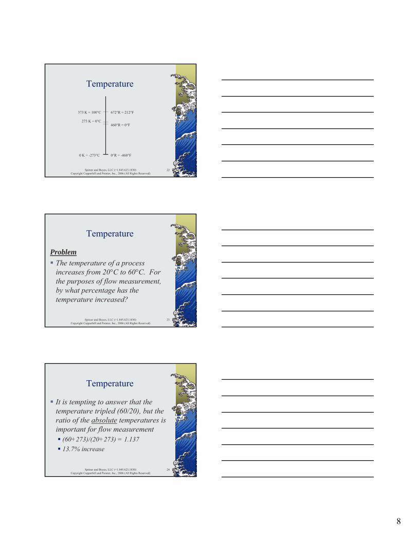
0 K = -273°C 0°R = -460°F
460°R = 0°F273 K = 0°C
373 K = 100°C 672°R = 212°F
Spitzer and Boyes, LLC (+1.845.623.1830)Copyright Copperhill and Pointer, Inc., 2006 (All Rights Reserved)
23
Temperature
ProblemThe temperature of a process increases from 20°C to 60°C. For the purposes of flow measurement, by what percentage has the temperature increased?
Spitzer and Boyes, LLC (+1.845.623.1830)Copyright Copperhill and Pointer, Inc., 2006 (All Rights Reserved)
24
Temperature
It is tempting to answer that the temperature tripled (60/20), but the ratio of the absolute temperatures is important for flow measurement
(60+273)/(20+273) = 1.13713.7% increase
9
Spitzer and Boyes, LLC (+1.845.623.1830)Copyright Copperhill and Pointer, Inc., 2006 (All Rights Reserved)
25
Fluid Properties
TemperaturePressureDensity and Fluid ExpansionTypes of FlowInside Pipe DiameterViscosityReynolds Number and Velocity ProfileHydraulic Phenomena
Spitzer and Boyes, LLC (+1.845.623.1830)Copyright Copperhill and Pointer, Inc., 2006 (All Rights Reserved)
26
Pressure
Pressure is defined as the ratio of a force divided by the area over which it is exerted (P=F/A)
Spitzer and Boyes, LLC (+1.845.623.1830)Copyright Copperhill and Pointer, Inc., 2006 (All Rights Reserved)
27
Pressure
ProblemWhat is the pressure exerted on a table by a 2 inch cube weighing 5 pounds?
(5 lb) / (4 inch2) = 1.25 lb/in2
If the cube were balanced on a 0.1 inch diameter rod, the pressure on the table would be 636 lb/in2
10
Spitzer and Boyes, LLC (+1.845.623.1830)Copyright Copperhill and Pointer, Inc., 2006 (All Rights Reserved)
28
Pressure
Atmospheric pressure is caused by the force exerted by the atmosphere on the surface of the earth
2.31 feet WC / psi10.2 meters WC / bar
Spitzer and Boyes, LLC (+1.845.623.1830)Copyright Copperhill and Pointer, Inc., 2006 (All Rights Reserved)
29
Pressure
Removing gas from a container lowers the pressure in the container
If all gas is removed, absolute zero pressure (full vacuum) is reached at approximately -1.01325 bar (-14.696 psig)
Spitzer and Boyes, LLC (+1.845.623.1830)Copyright Copperhill and Pointer, Inc., 2006 (All Rights Reserved)
30
Pressure
Absolute pressure scales are relative to absolute zero pressure
Absolute zero pressure Full vacuum = 0 bar abs (0 psia)bar abs = bar + 1.01325psia = psig + 14.696
11
Spitzer and Boyes, LLC (+1.845.623.1830)Copyright Copperhill and Pointer, Inc., 2006 (All Rights Reserved)
31
Pressure
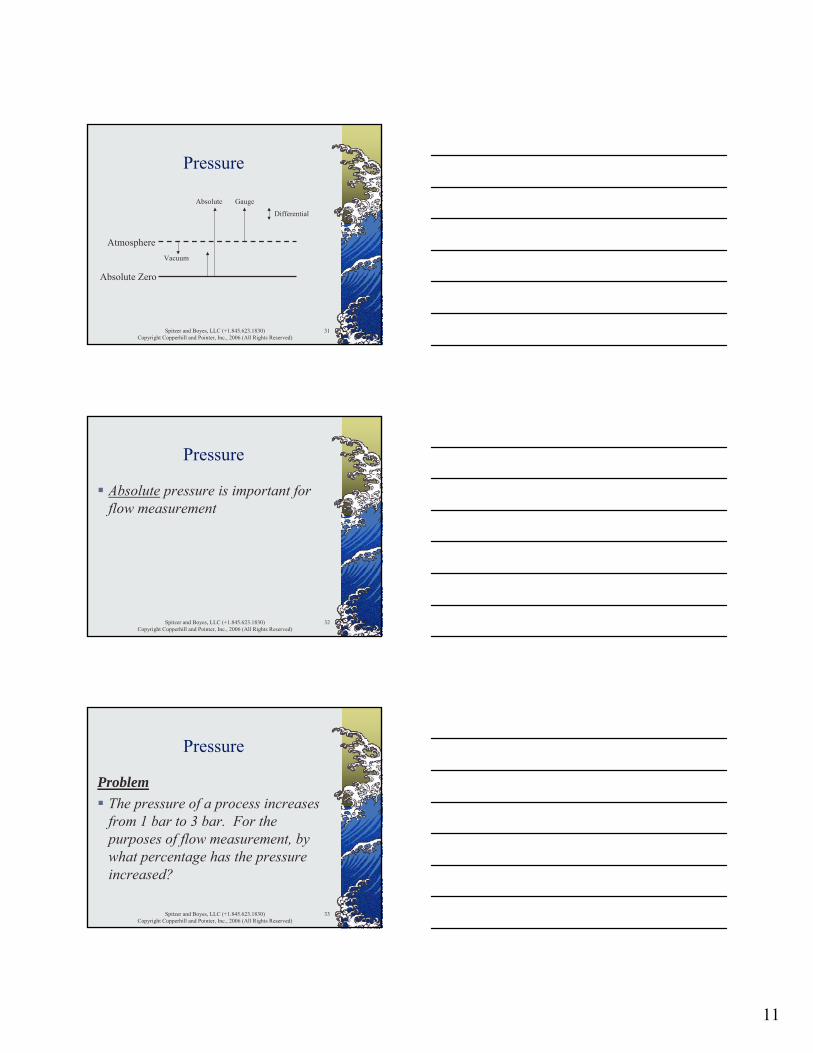
Atmosphere
Absolute Zero
Vacuum
Absolute Gauge
Differential
Spitzer and Boyes, LLC (+1.845.623.1830)Copyright Copperhill and Pointer, Inc., 2006 (All Rights Reserved)
32
Pressure
Absolute pressure is important for flow measurement
Spitzer and Boyes, LLC (+1.845.623.1830)Copyright Copperhill and Pointer, Inc., 2006 (All Rights Reserved)
33
Pressure
ProblemThe pressure of a process increases from 1 bar to 3 bar. For the purposes of flow measurement, by what percentage has the pressure increased?
12
Spitzer and Boyes, LLC (+1.845.623.1830)Copyright Copperhill and Pointer, Inc., 2006 (All Rights Reserved)
34
Pressure
It is tempting to answer that the pressure tripled (3/1), but the ratio of the absolute pressures is important for flow measurement
(3+1.01325)/(1+1.01325) = 1.99399.3% increase
Spitzer and Boyes, LLC (+1.845.623.1830)Copyright Copperhill and Pointer, Inc., 2006 (All Rights Reserved)
35
Fluid Properties
TemperaturePressureDensity and Fluid ExpansionTypes of FlowInside Pipe DiameterViscosityReynolds Number and Velocity ProfileHydraulic Phenomena
Spitzer and Boyes, LLC (+1.845.623.1830)Copyright Copperhill and Pointer, Inc., 2006 (All Rights Reserved)
36
Density and Fluid Expansion
Density is defined as the ratio of the mass of a fluid divided its volume (ρ=m/V)
13
Spitzer and Boyes, LLC (+1.845.623.1830)Copyright Copperhill and Pointer, Inc., 2006 (All Rights Reserved)
37
Density and Fluid Expansion
Specific Gravity of a liquid is the ratio of its operating density to that of water at standard conditions
SG = ρ liquid / ρ water at standard conditions
Spitzer and Boyes, LLC (+1.845.623.1830)Copyright Copperhill and Pointer, Inc., 2006 (All Rights Reserved)
38
Density and Fluid Expansion
ProblemWhat is the density of air in a 3.2 ft3 filled cylinder that has a weight of 28.2 and 32.4 pounds before and after filling respectively?
Spitzer and Boyes, LLC (+1.845.623.1830)Copyright Copperhill and Pointer, Inc., 2006 (All Rights Reserved)
39
Density and Fluid Expansion
The weight of the air in the empty cylinder is taken into account
Mass =(32.4-28.2)+(3.2•0.075)= 4.44 lb
Volume = 3.2 ft3
Density = 4.44/3.2 = 1.39 lb/ft3
14
Spitzer and Boyes, LLC (+1.845.623.1830)Copyright Copperhill and Pointer, Inc., 2006 (All Rights Reserved)
40
Density and Fluid Expansion
The density of most liquids is nearly unaffected by pressureExpansion of liquids
V = V0 (1 + β•ΔT)V = new volumeV0 = old volumeβ = cubical coefficient of expansionΔT = temperature change
Spitzer and Boyes, LLC (+1.845.623.1830)Copyright Copperhill and Pointer, Inc., 2006 (All Rights Reserved)
41
Density and Fluid Expansion
ProblemWhat is the change in density of a liquid caused by a 10°C temperature rise where β is 0.0009 per °C ?
Spitzer and Boyes, LLC (+1.845.623.1830)Copyright Copperhill and Pointer, Inc., 2006 (All Rights Reserved)
42
Density and Fluid Expansion
Calculate the new volumeV = V0 (1 + 0.0009•10) = 1.009 V0
The volume of the liquid increased to 1.009 times the old volume, so the new density is (1/1.009) or 0.991 times the old density

15
Spitzer and Boyes, LLC (+1.845.623.1830)Copyright Copperhill and Pointer, Inc., 2006 (All Rights Reserved)
43
Density and Fluid Expansion
Expansion of solidsV = V0 (1 + β•ΔT)
where β = 3•αα = linear coefficient of expansion
Temperature coefficientStainless steel temperature coefficient is approximately 0.5% per 100°C
Spitzer and Boyes, LLC (+1.845.623.1830)Copyright Copperhill and Pointer, Inc., 2006 (All Rights Reserved)
44
Density and Fluid Expansion
ProblemWhat is the increase in size of metal caused by a 50°C temperature rise where the metal has a temperature coefficient of 0.5% per 100°C ?
Spitzer and Boyes, LLC (+1.845.623.1830)Copyright Copperhill and Pointer, Inc., 2006 (All Rights Reserved)
45
Density and Fluid Expansion
Calculate the change in size(0.5 • 50) = 0.25%Metals (such as stainless steel) can exhibit significant expansion
16
Spitzer and Boyes, LLC (+1.845.623.1830)Copyright Copperhill and Pointer, Inc., 2006 (All Rights Reserved)
46
Density and Fluid Expansion
Boyle’s Law states the the volume of an ideal gas at constant temperature varies inversely with absolutepressure
V = K / P
Spitzer and Boyes, LLC (+1.845.623.1830)Copyright Copperhill and Pointer, Inc., 2006 (All Rights Reserved)
47
Density and Fluid Expansion
New volume can be calculatedV = K / PV0 = K / P0
Dividing one equation by the other yields
V/V0 = P0 / P
Spitzer and Boyes, LLC (+1.845.623.1830)Copyright Copperhill and Pointer, Inc., 2006 (All Rights Reserved)
48
Density and Fluid Expansion
ProblemHow is the volume of an ideal gas at constant temperature and a pressure of 28 psig affected by a 5 psig pressure increase?
17
Spitzer and Boyes, LLC (+1.845.623.1830)Copyright Copperhill and Pointer, Inc., 2006 (All Rights Reserved)
49
Density and Fluid Expansion
Calculate the new volumeV/V0 = (28+14.7) / (28+5+14.7) = 0.895
V = 0.895 V0
Volume decreased by 10.5%
Spitzer and Boyes, LLC (+1.845.623.1830)Copyright Copperhill and Pointer, Inc., 2006 (All Rights Reserved)
50
Density and Fluid Expansion
Charles’ Law states the the volume of an ideal gas at constant pressure varies directly with absolutetemperature
V = K • T
Spitzer and Boyes, LLC (+1.845.623.1830)Copyright Copperhill and Pointer, Inc., 2006 (All Rights Reserved)
51
Density and Fluid Expansion
New volume can be calculatedV = K • TV0 = K • T0
Dividing one equation by the other yields
V/V0 = T / T0
18
Spitzer and Boyes, LLC (+1.845.623.1830)Copyright Copperhill and Pointer, Inc., 2006 (All Rights Reserved)
52
Density and Fluid Expansion
ProblemHow is the volume of an ideal gas at constant pressure and a temperature of 15ºC affected by a 10ºC decrease in temperature?
Spitzer and Boyes, LLC (+1.845.623.1830)Copyright Copperhill and Pointer, Inc., 2006 (All Rights Reserved)
53
Density and Fluid Expansion
Calculate the new volumeV/V0 = (273+15-10) / (273+15) = 0.965
V = 0.965 V0
Volume decreased by 3.5%
Spitzer and Boyes, LLC (+1.845.623.1830)Copyright Copperhill and Pointer, Inc., 2006 (All Rights Reserved)
54
Density and Fluid Expansion
Ideal Gas Law combines Boyle’s and Charles’ Laws
PV = n R T

19
Spitzer and Boyes, LLC (+1.845.623.1830)Copyright Copperhill and Pointer, Inc., 2006 (All Rights Reserved)
55
Density and Fluid Expansion
New volume can be calculatedP • V = n • R • TP0 • V0 = n • R • T0
Dividing one equation by the other yields
V/V0 = (P0 /P) • (T / T0)
Spitzer and Boyes, LLC (+1.845.623.1830)Copyright Copperhill and Pointer, Inc., 2006 (All Rights Reserved)
56
Density and Fluid Expansion
ProblemHow is the volume of an ideal gas at affected by a 10.5% decrease in volume due to temperature and a 3.5% decrease in volume due to pressure?
Spitzer and Boyes, LLC (+1.845.623.1830)Copyright Copperhill and Pointer, Inc., 2006 (All Rights Reserved)
57
Density and Fluid Expansion
Calculate the new volumeV/V0 = 0.895 • 0.965 = 0.864
V = 0.864 V0
Volume decreased by 13.6%
20
Spitzer and Boyes, LLC (+1.845.623.1830)Copyright Copperhill and Pointer, Inc., 2006 (All Rights Reserved)
58
Density and Fluid Expansion
Non-Ideal Gas Law takes into account non-ideal behavior
PV = n R T Z
Spitzer and Boyes, LLC (+1.845.623.1830)Copyright Copperhill and Pointer, Inc., 2006 (All Rights Reserved)
59
Density and Fluid Expansion
New volume can be calculatedP • V = n • R • T • ZP0 • V0 = n • R • T0 • Z0
Dividing one equation by the other yields
V/V0 = (P0 /P) • (T / T0) • (Z / Z0)
Spitzer and Boyes, LLC (+1.845.623.1830)Copyright Copperhill and Pointer, Inc., 2006 (All Rights Reserved)
60
Fluid Properties
TemperaturePressureDensity and Fluid ExpansionTypes of FlowInside Pipe DiameterViscosityReynolds Number and Velocity ProfileHydraulic Phenomena
21
Spitzer and Boyes, LLC (+1.845.623.1830)Copyright Copperhill and Pointer, Inc., 2006 (All Rights Reserved)
61
Types of Flow
Q = A • vQ is the volumetric flow rateA is the cross-sectional area of the pipev is the average velocity of the fluid in the pipe
Spitzer and Boyes, LLC (+1.845.623.1830)Copyright Copperhill and Pointer, Inc., 2006 (All Rights Reserved)
62
Types of Flow
Typical Volumetric Flow Units(Q = A • v)ft2 • ft/sec = ft3/secm2 • m/sec = m3/secgallons per minute (gpm)liters per minute (lpm)cubic centimeters per minute (ccm)
Spitzer and Boyes, LLC (+1.845.623.1830)Copyright Copperhill and Pointer, Inc., 2006 (All Rights Reserved)
63
Types of Flow
W = ρ • QW is the mass flow rateρ is the fluid densityQ is the volumetric flow rate
22
Spitzer and Boyes, LLC (+1.845.623.1830)Copyright Copperhill and Pointer, Inc., 2006 (All Rights Reserved)
64
Types of Flow
Typical Mass Flow Units (W = ρ • Q)lb/ft3 • ft3/sec = lb/seckg/m3 • m3/sec = kg/secstandard cubic feet per minute (scfm)standard liters per minute (slpm)standard cubic centimeters per minute(sccm)
Spitzer and Boyes, LLC (+1.845.623.1830)Copyright Copperhill and Pointer, Inc., 2006 (All Rights Reserved)
65
Types of Flow
Q = A • vW = ρ • Q
Q volumetric flow rateW mass flow rate v fluid velocity½ ρv2 inferential flow rate
Spitzer and Boyes, LLC (+1.845.623.1830)Copyright Copperhill and Pointer, Inc., 2006 (All Rights Reserved)
66
Fluid Properties
TemperaturePressureDensity and Fluid ExpansionTypes of FlowInside Pipe DiameterViscosityReynolds Number and Velocity ProfileHydraulic Phenomena
23
Spitzer and Boyes, LLC (+1.845.623.1830)Copyright Copperhill and Pointer, Inc., 2006 (All Rights Reserved)
67
Inside Pipe Diameter
The inside pipe diameter (ID) is important for flow measurement
Pipes of the same size have the same outside diameter (OD)
Welding considerationsPipe wall thickness, and hence its ID, is determined by its schedule
Spitzer and Boyes, LLC (+1.845.623.1830)Copyright Copperhill and Pointer, Inc., 2006 (All Rights Reserved)
68
Inside Pipe Diameter
Pipe wall thickness increases with increasing pipe schedule
Schedule 40 pipes are considered “standard” wall thicknessSchedule 5 pipes have thin wallsSchedule 160 pipes have thick walls
Spitzer and Boyes, LLC (+1.845.623.1830)Copyright Copperhill and Pointer, Inc., 2006 (All Rights Reserved)
69
Inside Pipe Diameter
Nominal pipe sizeFor pipe sizes 12-inch and smaller, the nominal pipe size is the approximate ID of a Schedule 40 pipeFor pipe sizes 14-inch and larger, the nominal pipe size is the OD of the pipe
24
Spitzer and Boyes, LLC (+1.845.623.1830)Copyright Copperhill and Pointer, Inc., 2006 (All Rights Reserved)
70
Fluid Properties
TemperaturePressureDensity and Fluid ExpansionTypes of FlowInside Pipe DiameterViscosityReynolds Number and Velocity ProfileHydraulic Phenomena
Spitzer and Boyes, LLC (+1.845.623.1830)Copyright Copperhill and Pointer, Inc., 2006 (All Rights Reserved)
71
Viscosity
Viscosity is the ability of the fluid to flow over itselfUnits
cP, cStSaybolt Universal (at 100ºF, 210 ºF)Saybolt Furol (at 122ºF, 210 ºF)
Spitzer and Boyes, LLC (+1.845.623.1830)Copyright Copperhill and Pointer, Inc., 2006 (All Rights Reserved)
72
Viscosity
Viscosity can be highly temperature dependent
WaterHoney at 40°F, 80°F, and 120°F Peanut butter
25
Spitzer and Boyes, LLC (+1.845.623.1830)Copyright Copperhill and Pointer, Inc., 2006 (All Rights Reserved)
73
Fluid Properties
TemperaturePressureDensity and Fluid ExpansionTypes of FlowInside Pipe DiameterViscosityReynolds Number and Velocity ProfileHydraulic Phenomena
Spitzer and Boyes, LLC (+1.845.623.1830)Copyright Copperhill and Pointer, Inc., 2006 (All Rights Reserved)
74
Velocity Profile and Reynolds Number
Reynolds number is the ratio of inertial forces to viscous forces in the flowing stream
RD = 3160 • Q gpm • SG / (μcP • Din)
Spitzer and Boyes, LLC (+1.845.623.1830)Copyright Copperhill and Pointer, Inc., 2006 (All Rights Reserved)
75
Velocity Profile and Reynolds Number
Reynolds number can be used as an indication of how the fluid is flowing in the pipe Flow regimes based on RD
Laminar < 2000Transitional 2000 - 4000Turbulent > 4000
26
Spitzer and Boyes, LLC (+1.845.623.1830)Copyright Copperhill and Pointer, Inc., 2006 (All Rights Reserved)
76
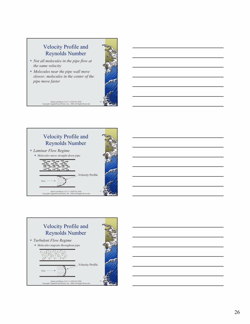
Velocity Profile and Reynolds Number
Not all molecules in the pipe flow at the same velocityMolecules near the pipe wall move slower; molecules in the center of the pipe move faster
Spitzer and Boyes, LLC (+1.845.623.1830)Copyright Copperhill and Pointer, Inc., 2006 (All Rights Reserved)
77
Velocity Profile and Reynolds Number
Flow
Velocity Profile
Laminar Flow RegimeMolecules move straight down pipe
Spitzer and Boyes, LLC (+1.845.623.1830)Copyright Copperhill and Pointer, Inc., 2006 (All Rights Reserved)
78
Velocity Profile and Reynolds Number
Flow
Velocity Profile
Turbulent Flow RegimeMolecules migrate throughout pipe

27
Spitzer and Boyes, LLC (+1.845.623.1830)Copyright Copperhill and Pointer, Inc., 2006 (All Rights Reserved)
79
Velocity Profile and Reynolds Number
Transitional Flow RegimeMolecules exhibit both laminar and turbulent behavior
Spitzer and Boyes, LLC (+1.845.623.1830)Copyright Copperhill and Pointer, Inc., 2006 (All Rights Reserved)
80
Velocity Profile and Reynolds Number
Many flowmeters require a good velocity profile to operate accuratelyObstructions in the piping system can distort the velocity profile
Elbows, tees, fittings, valves
Spitzer and Boyes, LLC (+1.845.623.1830)Copyright Copperhill and Pointer, Inc., 2006 (All Rights Reserved)
81
Velocity Profile and Reynolds Number
Flow
Velocity Profile (distorted)
A distorted velocity profile can introduce significant errors into the measurement of most flowmeters
28
Spitzer and Boyes, LLC (+1.845.623.1830)Copyright Copperhill and Pointer, Inc., 2006 (All Rights Reserved)
82
Velocity Profile and Reynolds Number
Good velocity profiles can be developedStraight run upstream and downstream
No fittings or valvesUpstream is usually longer and more important
Flow conditionerLocate control valve downstream of flowmeter
Spitzer and Boyes, LLC (+1.845.623.1830)Copyright Copperhill and Pointer, Inc., 2006 (All Rights Reserved)
83
Fluid Properties
TemperaturePressureDensity and Fluid ExpansionTypes of FlowInside Pipe DiameterViscosityReynolds Number and Velocity ProfileHydraulic Phenomena
Spitzer and Boyes, LLC (+1.845.623.1830)Copyright Copperhill and Pointer, Inc., 2006 (All Rights Reserved)
84
Hydraulic Phenomena
Vapor pressure is defined as the pressure at which a liquid and its vapor can exist in equilibrium
The vapor pressure of water at 100°C is atmospheric pressure (1.01325 bar abs) because water and steam can coexist
29
Spitzer and Boyes, LLC (+1.845.623.1830)Copyright Copperhill and Pointer, Inc., 2006 (All Rights Reserved)
85
Hydraulic Phenomena
A saturated vapor is in equilibrium with its liquid at its vapor pressure
Saturated steam at atmospheric pressure is at a temperature of 100°C
Spitzer and Boyes, LLC (+1.845.623.1830)Copyright Copperhill and Pointer, Inc., 2006 (All Rights Reserved)
86
Hydraulic Phenomena
A superheated vapor is a saturated vapor that is at a higher temperature than its saturation temperature
Steam at atmospheric pressure that is at 150°C is a superheated vapor with 50°C of superheat
Spitzer and Boyes, LLC (+1.845.623.1830)Copyright Copperhill and Pointer, Inc., 2006 (All Rights Reserved)
87
Hydraulic Phenomena
Flashing is the formation of gas (bubbles) in a liquid after the pressure of the liquid falls below its vapor pressure
Reducing the pressure of water at 100°C below atmospheric pressure (say 0.7 bar abs) will cause the water to boil
30
Spitzer and Boyes, LLC (+1.845.623.1830)Copyright Copperhill and Pointer, Inc., 2006 (All Rights Reserved)
88
Hydraulic Phenomena
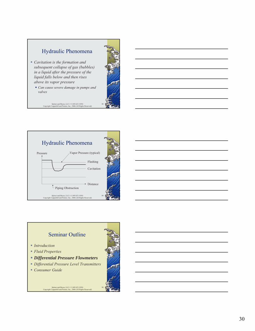
Cavitation is the formation and subsequent collapse of gas (bubbles) in a liquid after the pressure of the liquid falls below and then rises above its vapor pressure
Can cause severe damage in pumps and valves
Spitzer and Boyes, LLC (+1.845.623.1830)Copyright Copperhill and Pointer, Inc., 2006 (All Rights Reserved)
89
Hydraulic Phenomena
Distance
Pressure
Flashing
Cavitation
Piping Obstruction
Vapor Pressure (typical)
Spitzer and Boyes, LLC (+1.845.623.1830)Copyright Copperhill and Pointer, Inc., 2006 (All Rights Reserved)
90
Seminar Outline
IntroductionFluid PropertiesDifferential Pressure FlowmetersDifferential Pressure Level TransmittersConsumer Guide
31
Spitzer and Boyes, LLC (+1.845.623.1830)Copyright Copperhill and Pointer, Inc., 2006 (All Rights Reserved)
91
Differential PressureFlowmeters
Principle of OperationPrimary Flow ElementsTransmitter DesignsManifold DesignsInstallationAccessoriesPerformance
Spitzer and Boyes, LLC (+1.845.623.1830)Copyright Copperhill and Pointer, Inc., 2006 (All Rights Reserved)
92
Principle of Operation
A piping restriction is used to develop a pressure drop that is measured and used to infer fluid flow
Primary Flow ElementTransmitter (differential pressure)
Spitzer and Boyes, LLC (+1.845.623.1830)Copyright Copperhill and Pointer, Inc., 2006 (All Rights Reserved)
93
Principle of Operation
Bernoulli’s equation states that energy is approximately conserved across a constriction in a pipe
Static energy (pressure head)Kinetic energy (velocity head)Potential energy (elevation head)
32
Spitzer and Boyes, LLC (+1.845.623.1830)Copyright Copperhill and Pointer, Inc., 2006 (All Rights Reserved)
94
Principle of Operation
Bernoulli’s equationP/(ρ•g) + ½v2/g + y = constant
P = absolute pressureρ = densityg = acceleration of gravityv = fluid velocityy = elevation
Spitzer and Boyes, LLC (+1.845.623.1830)Copyright Copperhill and Pointer, Inc., 2006 (All Rights Reserved)
95
Principle of Operation
Equation of ContinuityQ = A•v
Q = flow (volumetric) A = cross-sectional areav = fluid velocity (average)
Spitzer and Boyes, LLC (+1.845.623.1830)Copyright Copperhill and Pointer, Inc., 2006 (All Rights Reserved)
96
Principle of Operation
Apply the equation of continuity and Bernoulli’s equation for flow in a horizontal pipe
Acceleration of gravity is constantNo elevation change
33
Spitzer and Boyes, LLC (+1.845.623.1830)Copyright Copperhill and Pointer, Inc., 2006 (All Rights Reserved)
97
Principle of Operation
Apply Bernoulli’s equation upstream and downstream of a restriction
P1 + ½ ρ•v12 = P2 + ½ ρ•v2
2
Spitzer and Boyes, LLC (+1.845.623.1830)Copyright Copperhill and Pointer, Inc., 2006 (All Rights Reserved)
98
Principle of Operation
Solve for the pressure difference and use the equation of continuity(P1 - P2) = ½ ρ•v2
2 - ½ ρ•v12
= ½ ρ [v22 - v1
2]= ½ ρ [(A1/A2)2 – 1]•v1
2
= ½ ρ [(A1/A2)2 – 1]•Q2/A12
= constant • ρ • Q2
Spitzer and Boyes, LLC (+1.845.623.1830)Copyright Copperhill and Pointer, Inc., 2006 (All Rights Reserved)
99
Principle of Operation
ΔP = constant • ρ • Q2
Fluid density affects the measurementPressure drop is proportional to the square of the flow rate
Squared output flowmeterDouble the flow… four times the differential

34
Spitzer and Boyes, LLC (+1.845.623.1830)Copyright Copperhill and Pointer, Inc., 2006 (All Rights Reserved)
100
Principle of Operation
Q = constant • (ΔP/ρ)½
Fluid density affects the measurementFlow rate is proportional to the square root of the differential pressure produced
Often called “square root flowmeter”
Spitzer and Boyes, LLC (+1.845.623.1830)Copyright Copperhill and Pointer, Inc., 2006 (All Rights Reserved)
101
Principle of Operation
Q is proportional to 1/ρ½
Fluid density affects the measurement by approximately -1/2% per % density change
Spitzer and Boyes, LLC (+1.845.623.1830)Copyright Copperhill and Pointer, Inc., 2006 (All Rights Reserved)
102
Principle of Operation
Liquid density changes are usually smallGas and vapor density changes can be large and may need compensation for accurate flow measurement
Flow computersMultivariable differential pressure transmitters

35
Spitzer and Boyes, LLC (+1.845.623.1830)Copyright Copperhill and Pointer, Inc., 2006 (All Rights Reserved)
103
Principle of Operation
ProblemWhat is the effect on a differential pressure flowmeter when the operating pressure of a gas is increased from 6 to 7 bar?
To simplify calculations, assume that atmospheric pressure is 1 bar abs
Spitzer and Boyes, LLC (+1.845.623.1830)Copyright Copperhill and Pointer, Inc., 2006 (All Rights Reserved)
104
Principle of Operation
The ratio of the densities is (7+1)/(6+1) = 1.14
The density of the gas increased 14 percentThe flow measurement is proportional to the inverse of the square root of the density which is (1/1.14)½ = 0.94
The flow measurement will be approximately 6 percent low
Spitzer and Boyes, LLC (+1.845.623.1830)Copyright Copperhill and Pointer, Inc., 2006 (All Rights Reserved)
105
Principle of Operation
ProblemCalculate the differential pressures produced at various percentages of full scale flow
Assume 0-100% flow corresponds to 0-100 differential pressure units
36
Spitzer and Boyes, LLC (+1.845.623.1830)Copyright Copperhill and Pointer, Inc., 2006 (All Rights Reserved)
106
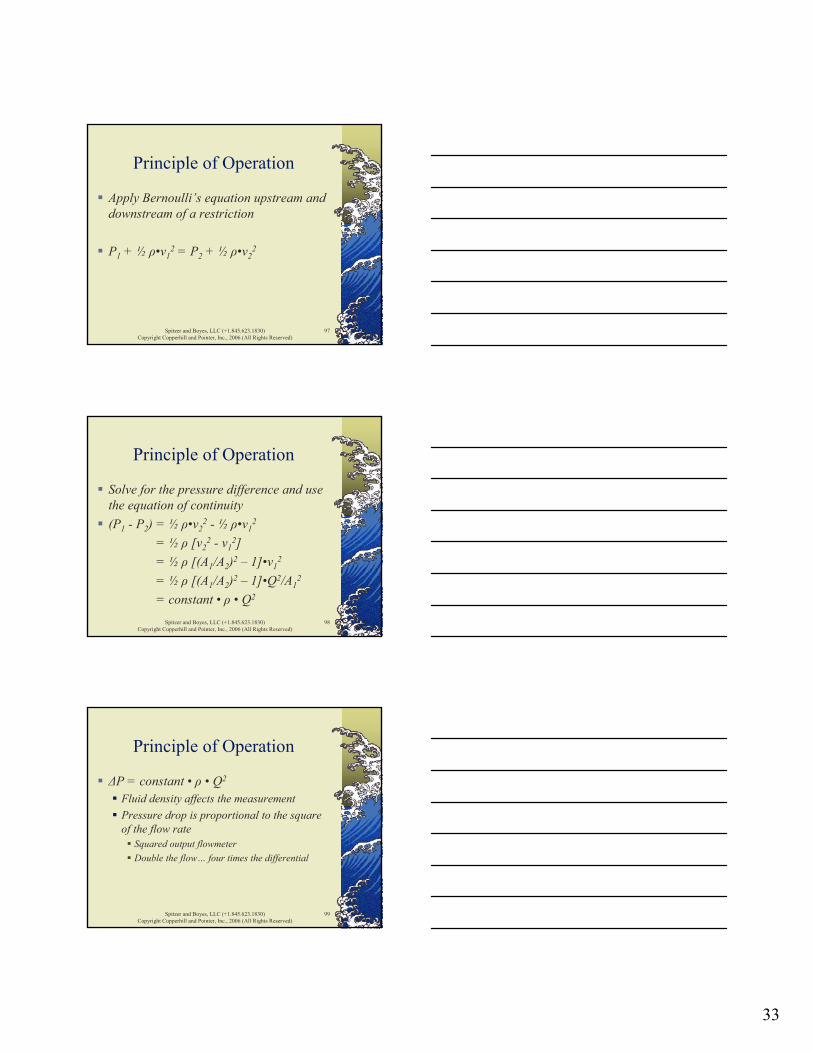
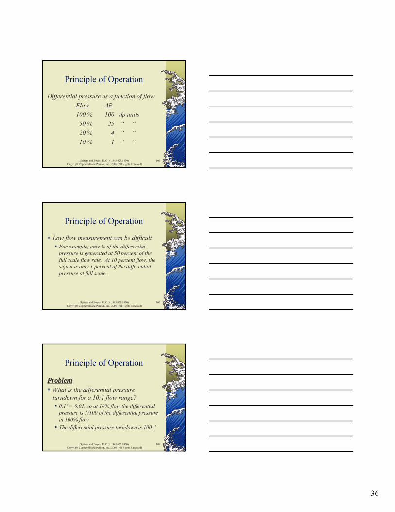
Principle of Operation
Differential pressure as a function of flowFlow ΔP100 % 100 dp units50 % 25 “ “20 % 4 “ “10 % 1 “ “
Spitzer and Boyes, LLC (+1.845.623.1830)Copyright Copperhill and Pointer, Inc., 2006 (All Rights Reserved)
107
Principle of Operation
Low flow measurement can be difficultFor example, only ¼ of the differential pressure is generated at 50 percent of the full scale flow rate. At 10 percent flow, the signal is only 1 percent of the differential pressure at full scale.
Spitzer and Boyes, LLC (+1.845.623.1830)Copyright Copperhill and Pointer, Inc., 2006 (All Rights Reserved)
108
Principle of Operation
ProblemWhat is the differential pressure turndown for a 10:1 flow range?
0.12 = 0.01, so at 10% flow the differential pressure is 1/100 of the differential pressure at 100% flowThe differential pressure turndown is 100:1
37
Spitzer and Boyes, LLC (+1.845.623.1830)Copyright Copperhill and Pointer, Inc., 2006 (All Rights Reserved)
109
Principle of Operation
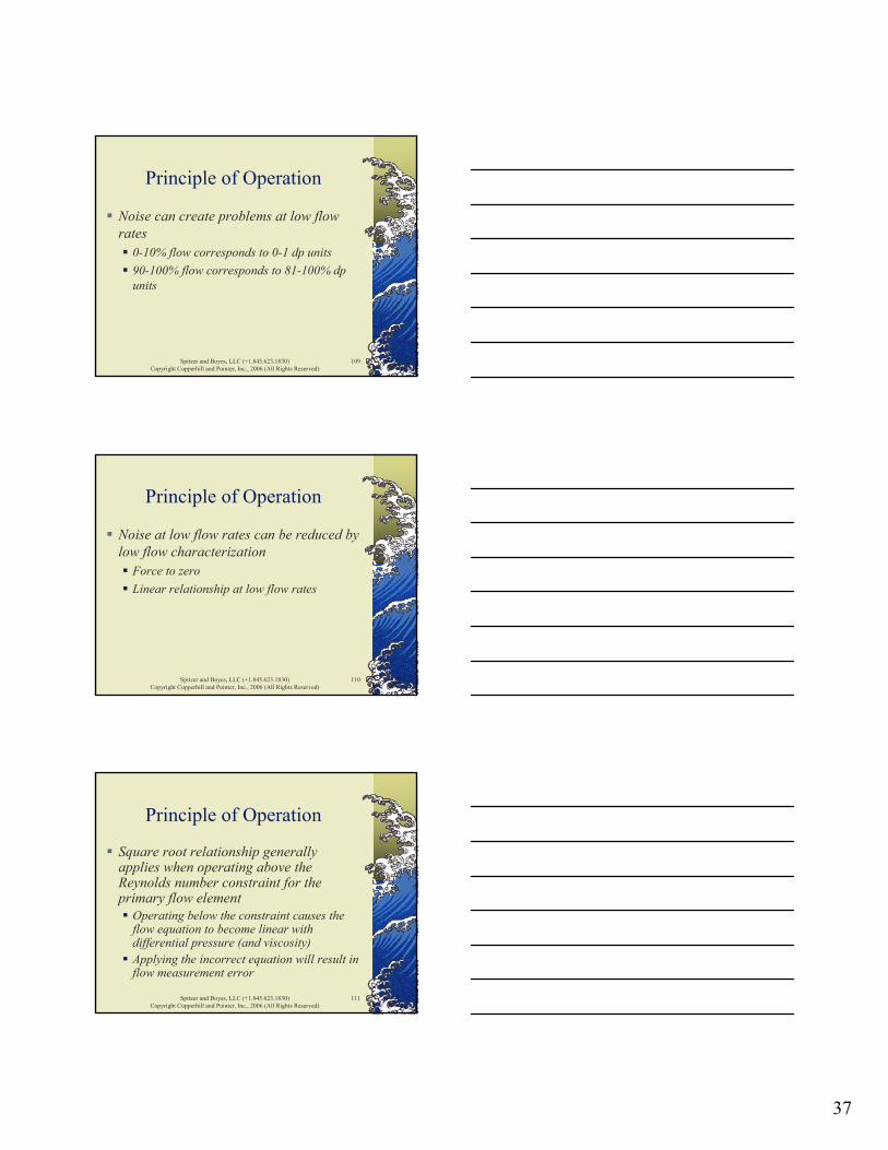
Noise can create problems at low flow rates
0-10% flow corresponds to 0-1 dp units90-100% flow corresponds to 81-100% dp units
Spitzer and Boyes, LLC (+1.845.623.1830)Copyright Copperhill and Pointer, Inc., 2006 (All Rights Reserved)
110
Principle of Operation
Noise at low flow rates can be reduced by low flow characterization
Force to zeroLinear relationship at low flow rates
Spitzer and Boyes, LLC (+1.845.623.1830)Copyright Copperhill and Pointer, Inc., 2006 (All Rights Reserved)
111
Principle of Operation
Square root relationship generally applies when operating above the Reynolds number constraint for the primary flow element
Operating below the constraint causes the flow equation to become linear with differential pressure (and viscosity) Applying the incorrect equation will result in flow measurement error
38
Spitzer and Boyes, LLC (+1.845.623.1830)Copyright Copperhill and Pointer, Inc., 2006 (All Rights Reserved)
112
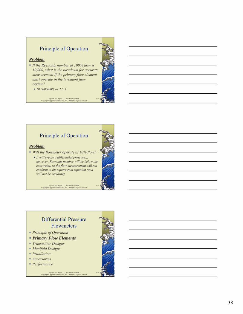
Principle of Operation
ProblemIf the Reynolds number at 100% flow is 10,000, what is the turndown for accurate measurement if the primary flow element must operate in the turbulent flow regime?
10,000/4000, or 2.5:1
Spitzer and Boyes, LLC (+1.845.623.1830)Copyright Copperhill and Pointer, Inc., 2006 (All Rights Reserved)
113
Principle of Operation
ProblemWill the flowmeter operate at 10% flow?
It will create a differential pressure…however, Reynolds number will be below the constraint, so the flow measurement will not conform to the square root equation (and will not be accurate)
Spitzer and Boyes, LLC (+1.845.623.1830)Copyright Copperhill and Pointer, Inc., 2006 (All Rights Reserved)
114
Differential PressureFlowmeters
Principle of OperationPrimary Flow ElementsTransmitter DesignsManifold Designs InstallationAccessoriesPerformance

39
Spitzer and Boyes, LLC (+1.845.623.1830)Copyright Copperhill and Pointer, Inc., 2006 (All Rights Reserved)
115
Orifice PlatePrimary Flow Element
Flow
Orifice Plate
Spitzer and Boyes, LLC (+1.845.623.1830)Copyright Copperhill and Pointer, Inc., 2006 (All Rights Reserved)
116
Orifice PlatePrimary Flow Element
Orifice Plate
FE-1004.000inch
Spitzer and Boyes, LLC (+1.845.623.1830)Copyright Copperhill and Pointer, Inc., 2006 (All Rights Reserved)
117
Orifice PlatePrimary Flow Element
ProprietaryOrifice Plate
FE-1004.000inch
40
Spitzer and Boyes, LLC (+1.845.623.1830)Copyright Copperhill and Pointer, Inc., 2006 (All Rights Reserved)
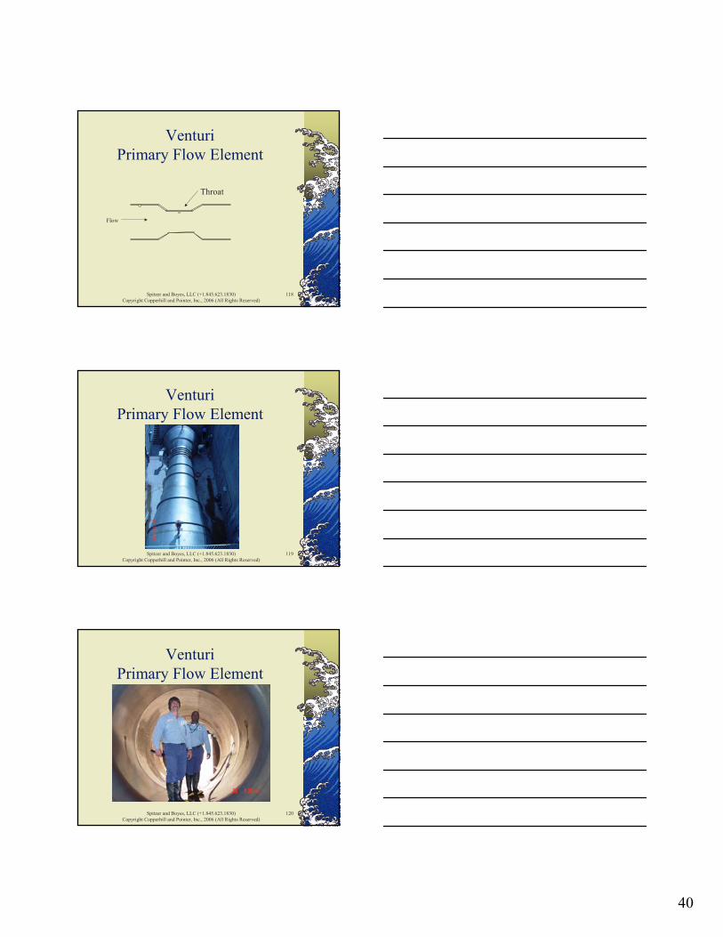
118
VenturiPrimary Flow Element
Flow
Throat
Spitzer and Boyes, LLC (+1.845.623.1830)Copyright Copperhill and Pointer, Inc., 2006 (All Rights Reserved)
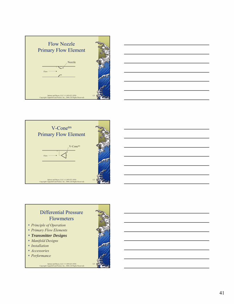
119
VenturiPrimary Flow Element
Spitzer and Boyes, LLC (+1.845.623.1830)Copyright Copperhill and Pointer, Inc., 2006 (All Rights Reserved)
120
VenturiPrimary Flow Element
41
Spitzer and Boyes, LLC (+1.845.623.1830)Copyright Copperhill and Pointer, Inc., 2006 (All Rights Reserved)
121
Flow Nozzle Primary Flow Element
Flow
Nozzle
Spitzer and Boyes, LLC (+1.845.623.1830)Copyright Copperhill and Pointer, Inc., 2006 (All Rights Reserved)
122
V-Conetm
Primary Flow Element
Flow
V-Conetm
Spitzer and Boyes, LLC (+1.845.623.1830)Copyright Copperhill and Pointer, Inc., 2006 (All Rights Reserved)
123
Differential PressureFlowmeters
Principle of OperationPrimary Flow ElementsTransmitter DesignsManifold Designs InstallationAccessoriesPerformance

42
Spitzer and Boyes, LLC (+1.845.623.1830)Copyright Copperhill and Pointer, Inc., 2006 (All Rights Reserved)
124
Differential PressureSensor Designs
CapacitanceDifferential TransformerForce BalancePiezoelectricPotentiometerSilicon ResonanceStrain Gage
Spitzer and Boyes, LLC (+1.845.623.1830)Copyright Copperhill and Pointer, Inc., 2006 (All Rights Reserved)
125
Differential Pressure Transmitter Designs
AnalogElectrical components subject to drift
Ambient temperatureProcess temperature
Two-wire design
Spitzer and Boyes, LLC (+1.845.623.1830)Copyright Copperhill and Pointer, Inc., 2006 (All Rights Reserved)
126
Differential Pressure Transmitter Designs
DigitalMicroprocessor is less susceptible to drift
Ambient temperatureProcess temperatureTemperature characterization in software
Remote communication (with HART)Two-wire design

43
Spitzer and Boyes, LLC (+1.845.623.1830)Copyright Copperhill and Pointer, Inc., 2006 (All Rights Reserved)
127
Differential Pressure Transmitter Designs
FieldbusMicroprocessor is less susceptible to drift
Ambient temperatureProcess temperatureTemperature characterization in software
Remote communicationIssues with multiple protocolsMulti-drop wiring
Spitzer and Boyes, LLC (+1.845.623.1830)Copyright Copperhill and Pointer, Inc., 2006 (All Rights Reserved)
128
Differential Pressure Transmitter Designs
Mechanical designSpacing between connections
Orifice flange taps
TraditionalLarger diaphragm/housing
CoplanarSmaller diaphragm/housing
Spitzer and Boyes, LLC (+1.845.623.1830)Copyright Copperhill and Pointer, Inc., 2006 (All Rights Reserved)
129
Differential Pressure Transmitter Designs
High static pressure designTypically lower performance
Safety designAutomatic diagnosticsRedundancyReliable components
44
Spitzer and Boyes, LLC (+1.845.623.1830)Copyright Copperhill and Pointer, Inc., 2006 (All Rights Reserved)
130
Differential PressureFlowmeters
Principle of OperationPrimary Flow ElementsTransmitter DesignsManifold DesignsInstallationAccessoriesPerformance
Spitzer and Boyes, LLC (+1.845.623.1830)Copyright Copperhill and Pointer, Inc., 2006 (All Rights Reserved)
131
Differential PressureMulti-Valve Manifold Designs
Multi-valve manifolds are used to isolate the transmitter from service for maintenance and calibration
One-piece integral assemblyMounted on transmitter
Spitzer and Boyes, LLC (+1.845.623.1830)Copyright Copperhill and Pointer, Inc., 2006 (All Rights Reserved)
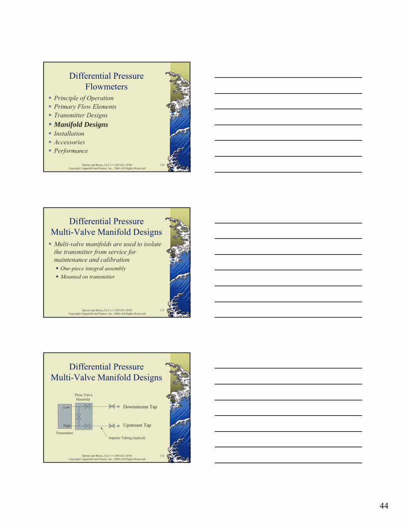
132
Differential PressureMulti-Valve Manifold Designs
Upstream Tap
Downstream Tap
High
Low
TransmitterImpulse Tubing (typical)
Three ValveManifold
45
Spitzer and Boyes, LLC (+1.845.623.1830)Copyright Copperhill and Pointer, Inc., 2006 (All Rights Reserved)
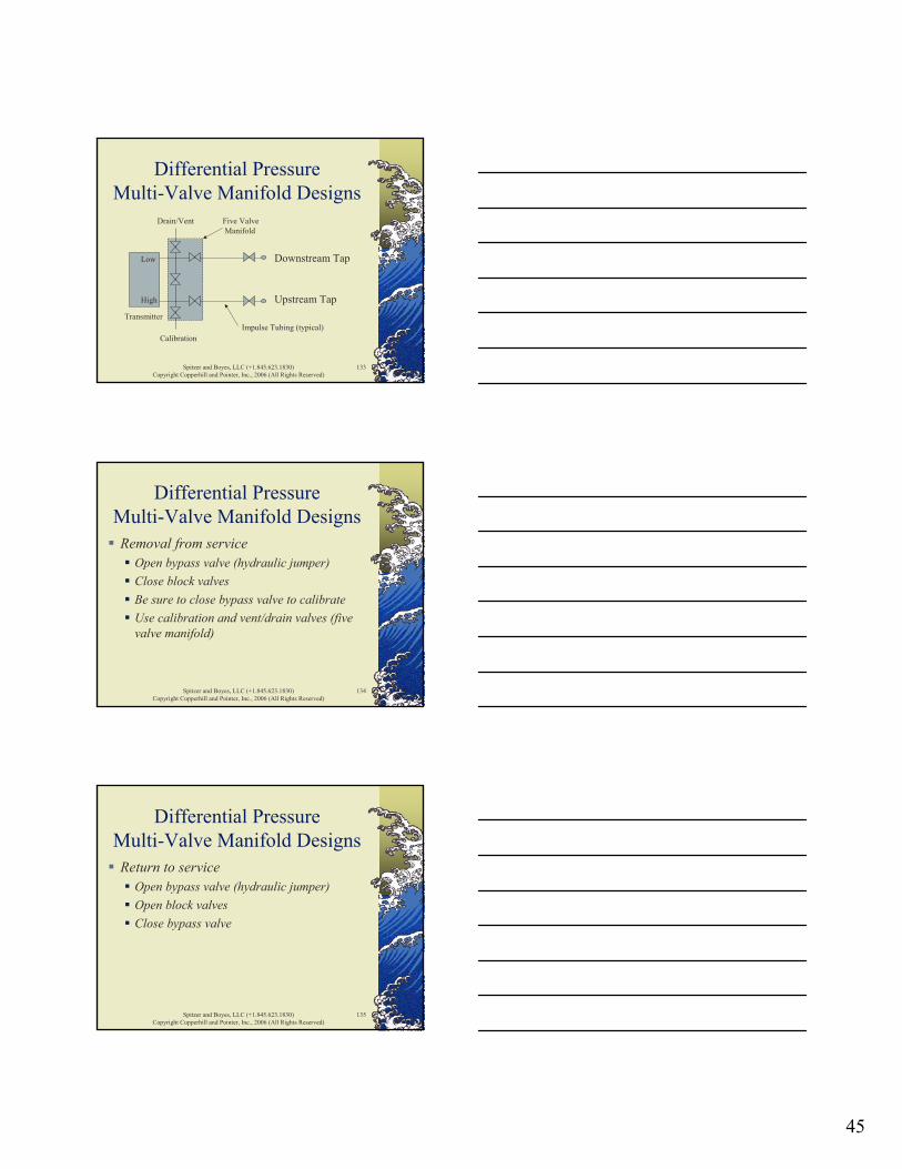
133
Differential PressureMulti-Valve Manifold Designs
Upstream Tap
Downstream Tap
High
Low
TransmitterImpulse Tubing (typical)
Five ValveManifold
Drain/Vent
Calibration
Spitzer and Boyes, LLC (+1.845.623.1830)Copyright Copperhill and Pointer, Inc., 2006 (All Rights Reserved)
134
Differential PressureMulti-Valve Manifold Designs
Removal from serviceOpen bypass valve (hydraulic jumper)Close block valvesBe sure to close bypass valve to calibrateUse calibration and vent/drain valves (five valve manifold)
Spitzer and Boyes, LLC (+1.845.623.1830)Copyright Copperhill and Pointer, Inc., 2006 (All Rights Reserved)
135
Differential PressureMulti-Valve Manifold Designs
Return to serviceOpen bypass valve (hydraulic jumper)Open block valvesClose bypass valve
46
Spitzer and Boyes, LLC (+1.845.623.1830)Copyright Copperhill and Pointer, Inc., 2006 (All Rights Reserved)
136
Differential PressureMulti-Valve Manifold Designs
Removal and return to service procedure may be different when flow of fluid in tubing/transmitter is dangerous
High pressure superheated steam
Spitzer and Boyes, LLC (+1.845.623.1830)Copyright Copperhill and Pointer, Inc., 2006 (All Rights Reserved)
137
Differential PressureFlowmeters
Principle of OperationPrimary Flow ElementsTransmitter DesignsManifold DesignsInstallationAccessoriesPerformance
Spitzer and Boyes, LLC (+1.845.623.1830)Copyright Copperhill and Pointer, Inc., 2006 (All Rights Reserved)
138
Principle of Operation
The quality of measurement is predicated on:
Proper installation of the primary flow elementProper operation of the primary flow element (for example, Reynolds number)Accurate measurement of the differential pressure

47
Spitzer and Boyes, LLC (+1.845.623.1830)Copyright Copperhill and Pointer, Inc., 2006 (All Rights Reserved)
139
Installation
Fluid CharacteristicsPiping and HydraulicsImpulse TubingElectricalAmbient ConditionsCalibration
Spitzer and Boyes, LLC (+1.845.623.1830)Copyright Copperhill and Pointer, Inc., 2006 (All Rights Reserved)
140
Fluid Characteristics
Reynolds number within constraintsFluid must not plug impulse tubing
SolidsPurge fluidsDiaphragm seals (added measurement error)
Spitzer and Boyes, LLC (+1.845.623.1830)Copyright Copperhill and Pointer, Inc., 2006 (All Rights Reserved)
141
Fluid Characteristics
Within accurate flow rangeCorrosion and erosion
FlowmeterExotic (thin) diaphragm materials
CoatingGas in liquid streamImmiscible fluids

48
Spitzer and Boyes, LLC (+1.845.623.1830)Copyright Copperhill and Pointer, Inc., 2006 (All Rights Reserved)
142
Piping and Hydraulics
For liquids, keep flowmeter fullHydraulic design
Vertical riser preferredAvoid inverted U-tube
Be careful when flowing by gravity
Spitzer and Boyes, LLC (+1.845.623.1830)Copyright Copperhill and Pointer, Inc., 2006 (All Rights Reserved)
143
Piping and Hydraulics
For gases, avoid accumulation of liquidHydraulic design
Vertical riser preferredAvoid U-tube
Spitzer and Boyes, LLC (+1.845.623.1830)Copyright Copperhill and Pointer, Inc., 2006 (All Rights Reserved)
144
Piping and Hydraulics
Maintain good velocity profileLocate control valve downstream of flowmeterProvide adequate straight run
Locate most straight run upstreamInstall flow conditioner
Use full face gaskets
49
Spitzer and Boyes, LLC (+1.845.623.1830)Copyright Copperhill and Pointer, Inc., 2006 (All Rights Reserved)
145
Piping and Hydraulics
Wetted parts compatible with fluidPipe quality
Use smooth round pipe with known inside diameter, wall thickness, and materialPurchasing the flowmeter and piping section controls pipe quality
Spitzer and Boyes, LLC (+1.845.623.1830)Copyright Copperhill and Pointer, Inc., 2006 (All Rights Reserved)
146
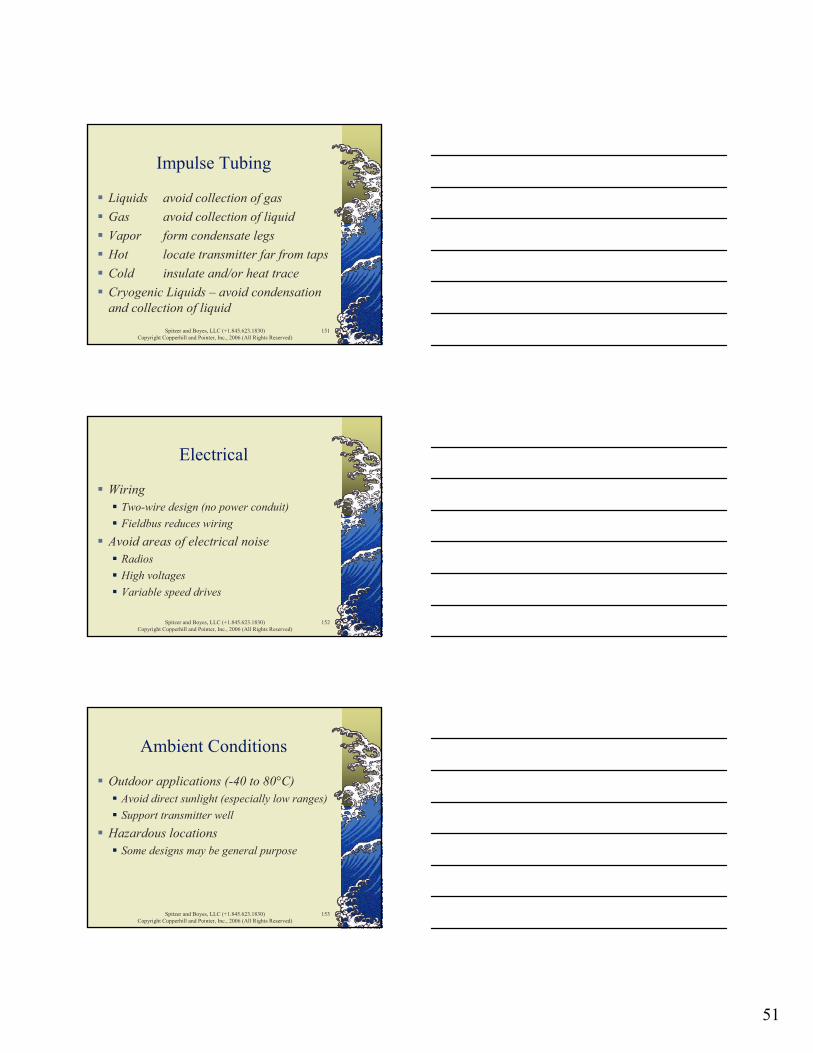
Impulse Tubing
Liquid
No! (gas)
No! (dirt)
Liquid FlowTransmitters
HL
OrificePlate
Spitzer and Boyes, LLC (+1.845.623.1830)Copyright Copperhill and Pointer, Inc., 2006 (All Rights Reserved)
147
Impulse Tubing
Gas
No! (dirt, condensate)
Gas Flow
Transmitters LHOrificePlate

50
Spitzer and Boyes, LLC (+1.845.623.1830)Copyright Copperhill and Pointer, Inc., 2006 (All Rights Reserved)
148
Impulse Tubing
Steam
No! (dirt, condensate)
Steam Flow
Transmitters
HL
OrificePlate
Condensate legs(typical)
Spitzer and Boyes, LLC (+1.845.623.1830)Copyright Copperhill and Pointer, Inc., 2006 (All Rights Reserved)
149
Impulse Tubing
SteamFlow
HL
OrificePlate
Condensate legs(same height)
Same Elevation(shown offset)
Spitzer and Boyes, LLC (+1.845.623.1830)Copyright Copperhill and Pointer, Inc., 2006 (All Rights Reserved)
150
Impulse Tubing
Cryogenic Liquid
No! (dirt)
CryogenicLiquid Flow
Transmitters LHOrificePlate
51
Spitzer and Boyes, LLC (+1.845.623.1830)Copyright Copperhill and Pointer, Inc., 2006 (All Rights Reserved)
151
Impulse Tubing
Liquids avoid collection of gasGas avoid collection of liquidVapor form condensate legsHot locate transmitter far from tapsCold insulate and/or heat traceCryogenic Liquids – avoid condensation and collection of liquid
Spitzer and Boyes, LLC (+1.845.623.1830)Copyright Copperhill and Pointer, Inc., 2006 (All Rights Reserved)
152
Electrical
WiringTwo-wire design (no power conduit)Fieldbus reduces wiring
Avoid areas of electrical noiseRadiosHigh voltagesVariable speed drives
Spitzer and Boyes, LLC (+1.845.623.1830)Copyright Copperhill and Pointer, Inc., 2006 (All Rights Reserved)
153
Ambient Conditions
Outdoor applications (-40 to 80°C)Avoid direct sunlight (especially low ranges)Support transmitter well
Hazardous locationsSome designs may be general purpose
52
Spitzer and Boyes, LLC (+1.845.623.1830)Copyright Copperhill and Pointer, Inc., 2006 (All Rights Reserved)
154
Calibration
GIGO (garbage in – garbage out)Entering correct information correctly is critical
Calibration range
Spitzer and Boyes, LLC (+1.845.623.1830)Copyright Copperhill and Pointer, Inc., 2006 (All Rights Reserved)
155
Calibration
Internal alignment (digital transmitters)Pressure sourceDigital indication in transmitterDigital output indication in transmitterAnalog signal
Spitzer and Boyes, LLC (+1.845.623.1830)Copyright Copperhill and Pointer, Inc., 2006 (All Rights Reserved)
156
Calibration
Zero in fieldPosition effectsPressure effects
53
Spitzer and Boyes, LLC (+1.845.623.1830)Copyright Copperhill and Pointer, Inc., 2006 (All Rights Reserved)
157
Differential PressureFlowmeters
Principle of OperationPrimary Flow ElementsTransmitter DesignsManifold Designs InstallationAccessoriesPerformance
Spitzer and Boyes, LLC (+1.845.623.1830)Copyright Copperhill and Pointer, Inc., 2006 (All Rights Reserved)
158
Accessories
Wetted partsDiaphragm (thin)FlangesDrain/vent valvesMaterials
Stainless steel, Monel, Hastelloy, tantalum
O-rings/gaskets (TFE, Vitontm)
Spitzer and Boyes, LLC (+1.845.623.1830)Copyright Copperhill and Pointer, Inc., 2006 (All Rights Reserved)
159
Accessories
Non-wetted partsFill fluids
Silicone, halocarbon
External housing

54
Spitzer and Boyes, LLC (+1.845.623.1830)Copyright Copperhill and Pointer, Inc., 2006 (All Rights Reserved)
160
Accessories
TransmitterNEMA 4X and IP67 (IP68)Hazardous locationsIntrinsically safeHART, Foundation Fieldbus, ProfibusMounting bracket
Spitzer and Boyes, LLC (+1.845.623.1830)Copyright Copperhill and Pointer, Inc., 2006 (All Rights Reserved)
161
Differential PressureFlowmeters
Principle of OperationPrimary Flow ElementsTransmitter DesignsManifold Designs InstallationAccessoriesPerformance
Spitzer and Boyes, LLC (+1.845.623.1830)Copyright Copperhill and Pointer, Inc., 2006 (All Rights Reserved)
162
Flowmeter Performance
DefinitionsPerformance StatementsReference PerformanceActual Performance
55
Spitzer and Boyes, LLC (+1.845.623.1830)Copyright Copperhill and Pointer, Inc., 2006 (All Rights Reserved)
163
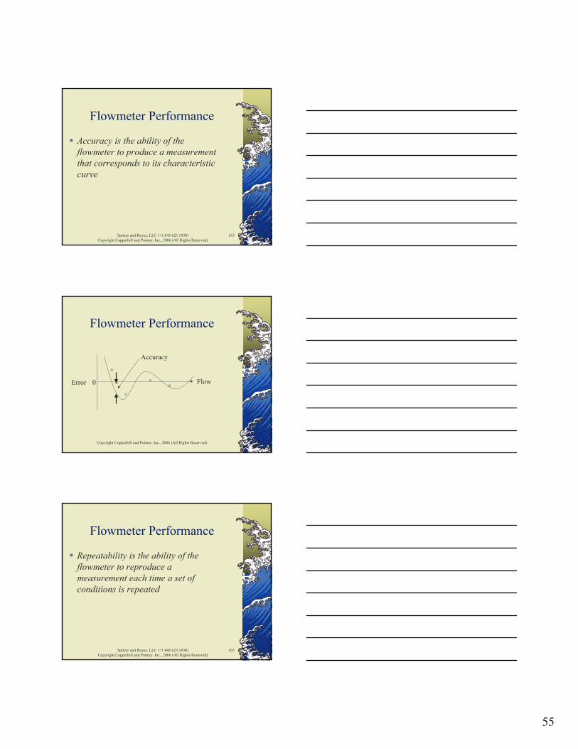
Flowmeter Performance
Accuracy is the ability of the flowmeter to produce a measurement that corresponds to its characteristic curve
Copyright Copperhill and Pointer, Inc., 2006 (All Rights Reserved)
Flowmeter Performance
FlowError 0
Accuracy
Spitzer and Boyes, LLC (+1.845.623.1830)Copyright Copperhill and Pointer, Inc., 2006 (All Rights Reserved)
165
Flowmeter Performance
Repeatability is the ability of the flowmeter to reproduce a measurement each time a set of conditions is repeated
56
Copyright Copperhill and Pointer, Inc., 2006 (All Rights Reserved)
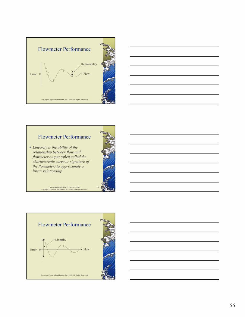
Flowmeter Performance
FlowError 0
Repeatability
Spitzer and Boyes, LLC (+1.845.623.1830)Copyright Copperhill and Pointer, Inc., 2006 (All Rights Reserved)
167
Flowmeter Performance
Linearity is the ability of the relationship between flow and flowmeter output (often called the characteristic curve or signature of the flowmeter) to approximate a linear relationship
Copyright Copperhill and Pointer, Inc., 2006 (All Rights Reserved)
Flowmeter Performance
FlowError 0
Linearity

57
Spitzer and Boyes, LLC (+1.845.623.1830)Copyright Copperhill and Pointer, Inc., 2006 (All Rights Reserved)
169
Flowmeter Performance
Flowmeter suppliers often specify the composite accuracy that represents the combined effects of repeatability, linearity and accuracy
Copyright Copperhill and Pointer, Inc., 2006 (All Rights Reserved)
Flowmeter Performance
FlowError 0
Flow Range
Composite Accuracy (in Flow Range)
Spitzer and Boyes, LLC (+1.845.623.1830)Copyright Copperhill and Pointer, Inc., 2006 (All Rights Reserved)
171
Flowmeter Performance
DefinitionsPerformance StatementsReference PerformanceActual Performance

58
Spitzer and Boyes, LLC (+1.845.623.1830)Copyright Copperhill and Pointer, Inc., 2006 (All Rights Reserved)
172
Performance Statements
Percent of ratePercent of full scalePercent of meter capacity (upper range limit)Percent of calibrated span
Spitzer and Boyes, LLC (+1.845.623.1830)Copyright Copperhill and Pointer, Inc., 2006 (All Rights Reserved)
173
Performance Statements
1% of rate performance at different flow rates with a 0-100 unit flow range
100% flow 0.01•100 1.00 unit50% flow 0.01•50 0.50 unit25% flow 0.01•25 0.25 unit10% flow 0.01•10 0.10 unit
Spitzer and Boyes, LLC (+1.845.623.1830)Copyright Copperhill and Pointer, Inc., 2006 (All Rights Reserved)
174
Performance Statements
Flow%RateError
0
10
-10
1% Rate Performance
59
Spitzer and Boyes, LLC (+1.845.623.1830)Copyright Copperhill and Pointer, Inc., 2006 (All Rights Reserved)
175
Performance Statements
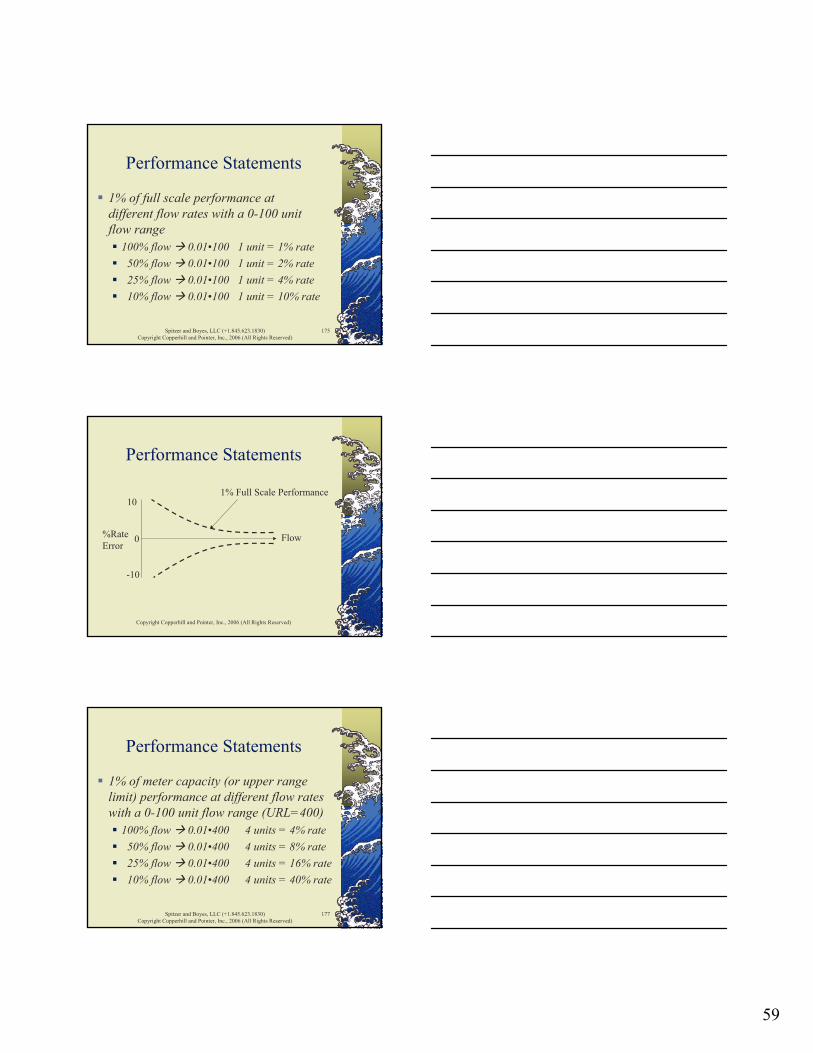
1% of full scale performance at different flow rates with a 0-100 unit flow range
100% flow 0.01•100 1 unit = 1% rate50% flow 0.01•100 1 unit = 2% rate25% flow 0.01•100 1 unit = 4% rate10% flow 0.01•100 1 unit = 10% rate
Copyright Copperhill and Pointer, Inc., 2006 (All Rights Reserved)
Performance Statements
Flow%RateError
0
10
-10
1% Full Scale Performance
Spitzer and Boyes, LLC (+1.845.623.1830)Copyright Copperhill and Pointer, Inc., 2006 (All Rights Reserved)
177
Performance Statements
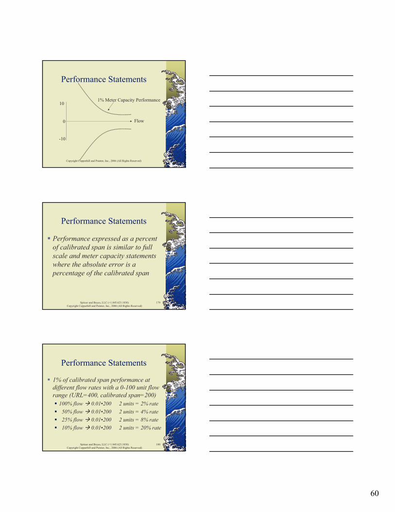
1% of meter capacity (or upper range limit) performance at different flow rates with a 0-100 unit flow range (URL=400)
100% flow 0.01•400 4 units = 4% rate50% flow 0.01•400 4 units = 8% rate25% flow 0.01•400 4 units = 16% rate10% flow 0.01•400 4 units = 40% rate
60
Copyright Copperhill and Pointer, Inc., 2006 (All Rights Reserved)
Performance Statements
Flow0
10
-10
1% Meter Capacity Performance
Spitzer and Boyes, LLC (+1.845.623.1830)Copyright Copperhill and Pointer, Inc., 2006 (All Rights Reserved)
179
Performance Statements
Performance expressed as a percent of calibrated span is similar to full scale and meter capacity statements where the absolute error is a percentage of the calibrated span
Spitzer and Boyes, LLC (+1.845.623.1830)Copyright Copperhill and Pointer, Inc., 2006 (All Rights Reserved)
180
Performance Statements
1% of calibrated span performance at different flow rates with a 0-100 unit flow range (URL=400, calibrated span=200)
100% flow 0.01•200 2 units = 2% rate50% flow 0.01•200 2 units = 4% rate25% flow 0.01•200 2 units = 8% rate10% flow 0.01•200 2 units = 20% rate

61
Copyright Copperhill and Pointer, Inc., 2006 (All Rights Reserved)
Performance Statements
Flow0
10
-10
1% of Calibrated Span Performance(assuming 50% URL)
Copyright Copperhill and Pointer, Inc., 2006 (All Rights Reserved)
Performance Statements
Flow%RateError
0
10
-10
1% Rate
1% Meter Capacity1% Full Scale
1% Calibrated Span(50%URL)
Spitzer and Boyes, LLC (+1.845.623.1830)Copyright Copperhill and Pointer, Inc., 2006 (All Rights Reserved)
183
Performance Statements
Performance statements can be manipulated because their meaning may not be clearly understoodTechnical assistance may be needed to analyze the statements
62
Spitzer and Boyes, LLC (+1.845.623.1830)Copyright Copperhill and Pointer, Inc., 2006 (All Rights Reserved)
184
Flowmeter Performance
DefinitionsPerformance StatementsReference PerformanceActual Performance
Spitzer and Boyes, LLC (+1.845.623.1830)Copyright Copperhill and Pointer, Inc., 2006 (All Rights Reserved)
185
Reference Performance
Reference performance is the quality of measurement at a nominal set of operating conditions, such as:
Water at 20°C in ambient conditions of 20°C and 50 percent relative humidityLong straight runPulse output
Spitzer and Boyes, LLC (+1.845.623.1830)Copyright Copperhill and Pointer, Inc., 2006 (All Rights Reserved)
186
Reference Performance
In the context of the industrial world, reference performance reflects performance under controlled laboratory conditions
63
Spitzer and Boyes, LLC (+1.845.623.1830)Copyright Copperhill and Pointer, Inc., 2006 (All Rights Reserved)
187
Reference Performance
Performance of the primary flow element and the transmitter must be taken into account to determine performance of flowmeter system
Spitzer and Boyes, LLC (+1.845.623.1830)Copyright Copperhill and Pointer, Inc., 2006 (All Rights Reserved)
188
Reference Performance
Hypothetical primary flow element1% rate Rd > 4000 and Q>10% FSOtherwise undefinedAssumes correct design, construction, installation, calibration, and operation
Spitzer and Boyes, LLC (+1.845.623.1830)Copyright Copperhill and Pointer, Inc., 2006 (All Rights Reserved)
189
Reference Performance
Hypothetical differential pressure transmitter
0.075% calibrated spanCalibrated for 0-100 unitsFactory calibrated at upper range limit (URL) of 400 units
64
Spitzer and Boyes, LLC (+1.845.623.1830)Copyright Copperhill and Pointer, Inc., 2006 (All Rights Reserved)
190
Reference Performance
ProblemWhat is the measurement error associated with the performance of the hypothetical differential pressure transmitter?
Spitzer and Boyes, LLC (+1.845.623.1830)Copyright Copperhill and Pointer, Inc., 2006 (All Rights Reserved)
191
Reference Performance
The calibrated span is 400, so the differential pressure measurement error is 0.10% of 400, or 0.4 units at all differential pressures
Spitzer and Boyes, LLC (+1.845.623.1830)Copyright Copperhill and Pointer, Inc., 2006 (All Rights Reserved)
192
Reference Performance
ProblemWhat is the flow measurement error associated with the performance of the hypothetical differential pressure transmitter?
65
Spitzer and Boyes, LLC (+1.845.623.1830)Copyright Copperhill and Pointer, Inc., 2006 (All Rights Reserved)
193
Reference Performance
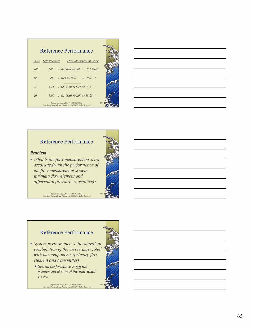
Flow Diff. Pressure Flow Measurement Error___________
100 100 1-√(100±0.4)/100 or 0.2 %rate___________
50 25 1-√(25±0.4)/25 or 0.8 “___________
25 6.25 1-√(6.25±0.4)/6.25 or 3.2 “___________
10 1.00 1-√(1.00±0.4)/1.00 or 18-23 “
Spitzer and Boyes, LLC (+1.845.623.1830)Copyright Copperhill and Pointer, Inc., 2006 (All Rights Reserved)
194
Reference Performance
ProblemWhat is the flow measurement error associated with the performance of the flow measurement system (primary flow element and differential pressure transmitter)?
Spitzer and Boyes, LLC (+1.845.623.1830)Copyright Copperhill and Pointer, Inc., 2006 (All Rights Reserved)
195
Reference Performance
System performance is the statistical combination of the errors associated with the components (primary flow element and transmitter)
System performance is not the mathematical sum of the individual errors

66
Spitzer and Boyes, LLC (+1.845.623.1830)Copyright Copperhill and Pointer, Inc., 2006 (All Rights Reserved)
196
Flowmeter Performance
DefinitionsPerformance StatementsReference PerformanceActual Performance
Spitzer and Boyes, LLC (+1.845.623.1830)Copyright Copperhill and Pointer, Inc., 2006 (All Rights Reserved)
197
Actual Performance
Operating EffectsAmbient conditions
HumidityPrecipitationTemperaturePressureDirect sunlight
Mounting OrientationStability (Drift)
Spitzer and Boyes, LLC (+1.845.623.1830)Copyright Copperhill and Pointer, Inc., 2006 (All Rights Reserved)
198
Actual Performance
Ambient Humidity and PrecipitationMany flowmeters are rated to 10-90% relative humidity (non-condensing)Outdoor locations are subject to 100% relative humidity and precipitation in various forms

67
Spitzer and Boyes, LLC (+1.845.623.1830)Copyright Copperhill and Pointer, Inc., 2006 (All Rights Reserved)
199
Actual Performance
Ambient Temperature and PressureInformation available to evaluate actual performance
Temperature effectPressure effect
Effects can be significant, even though the numbers seem small
Spitzer and Boyes, LLC (+1.845.623.1830)Copyright Copperhill and Pointer, Inc., 2006 (All Rights Reserved)
200
Actual Performance
ExampleThe error (at 25 percent of scale and a 0°C ambient) associated with a temperature effect of 0.01% full scale per °C can be calculated as:
0.01*(20-0)/25, or 0.80% rate
Spitzer and Boyes, LLC (+1.845.623.1830)Copyright Copperhill and Pointer, Inc., 2006 (All Rights Reserved)
201
Actual Performance
Reference accuracy performance statements are often discussedOperating effects, such as temperature and pressure effects are often only mentioned with prompting
Progressive disclosure

68
Spitzer and Boyes, LLC (+1.845.623.1830)Copyright Copperhill and Pointer, Inc., 2006 (All Rights Reserved)
202
Actual Performance
Ambient Direct SunlightCan cause temporary calibration shift
Low range transmitters
Spitzer and Boyes, LLC (+1.845.623.1830)Copyright Copperhill and Pointer, Inc., 2006 (All Rights Reserved)
203
Actual Performance
Mounting OrientationBench calibration vs. field calibration
Up to 5 mbar (2 inch WC) shift
Spitzer and Boyes, LLC (+1.845.623.1830)Copyright Copperhill and Pointer, Inc., 2006 (All Rights Reserved)
204
Actual Performance
StabilityDrift over time
Usually faster at beginning of periodSpecifications difficult to compare
Different ways over different periods of time
69
Spitzer and Boyes, LLC (+1.845.623.1830)Copyright Copperhill and Pointer, Inc., 2006 (All Rights Reserved)
205
Actual Performance
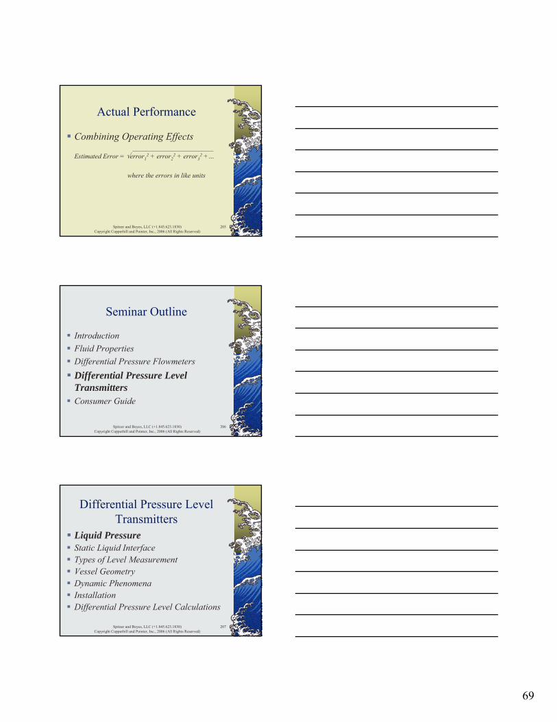
Combining Operating Effects________________________
Estimated Error = √error12 + error2
2 + error32 +…
where the errors in like units
Spitzer and Boyes, LLC (+1.845.623.1830)Copyright Copperhill and Pointer, Inc., 2006 (All Rights Reserved)
206
Seminar Outline
IntroductionFluid PropertiesDifferential Pressure FlowmetersDifferential Pressure Level TransmittersConsumer Guide
Spitzer and Boyes, LLC (+1.845.623.1830)Copyright Copperhill and Pointer, Inc., 2006 (All Rights Reserved)
207
Differential Pressure Level Transmitters
Liquid PressureStatic Liquid InterfaceTypes of Level MeasurementVessel GeometryDynamic PhenomenaInstallationDifferential Pressure Level Calculations
70
Spitzer and Boyes, LLC (+1.845.623.1830)Copyright Copperhill and Pointer, Inc., 2006 (All Rights Reserved)
208
Liquid Pressure
Bernoulli’s Theorem states that the pressure exerted by a liquid in an open tank is independent of the cross-sectional area of the liquid
Spitzer and Boyes, LLC (+1.845.623.1830)Copyright Copperhill and Pointer, Inc., 2006 (All Rights Reserved)
209
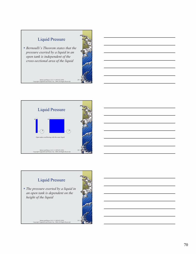
Liquid Pressure
Open tanks overflowing with the same liquid
Spitzer and Boyes, LLC (+1.845.623.1830)Copyright Copperhill and Pointer, Inc., 2006 (All Rights Reserved)
210
Liquid Pressure
The pressure exerted by a liquid in an open tank is dependent on the height of the liquid
71
Spitzer and Boyes, LLC (+1.845.623.1830)Copyright Copperhill and Pointer, Inc., 2006 (All Rights Reserved)
211
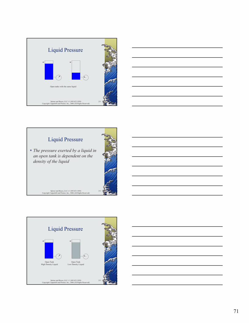
Liquid Pressure
Open tanks with the same liquid
Spitzer and Boyes, LLC (+1.845.623.1830)Copyright Copperhill and Pointer, Inc., 2006 (All Rights Reserved)
212
Liquid Pressure
The pressure exerted by a liquid in an open tank is dependent on the density of the liquid
Spitzer and Boyes, LLC (+1.845.623.1830)Copyright Copperhill and Pointer, Inc., 2006 (All Rights Reserved)
213
Liquid Pressure
Open TankHigh Density Liquid
Open TankLow Density Liquid
72
Spitzer and Boyes, LLC (+1.845.623.1830)Copyright Copperhill and Pointer, Inc., 2006 (All Rights Reserved)
214
Liquid Pressure
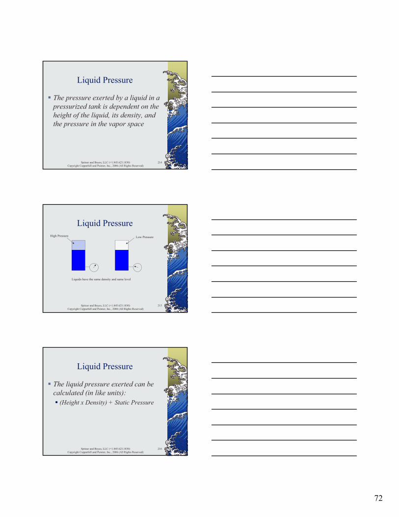
The pressure exerted by a liquid in a pressurized tank is dependent on the height of the liquid, its density, and the pressure in the vapor space
Spitzer and Boyes, LLC (+1.845.623.1830)Copyright Copperhill and Pointer, Inc., 2006 (All Rights Reserved)
215
Liquid PressureHigh Pressure Low Pressure
Liquids have the same density and same level
Spitzer and Boyes, LLC (+1.845.623.1830)Copyright Copperhill and Pointer, Inc., 2006 (All Rights Reserved)
216
Liquid Pressure
The liquid pressure exerted can be calculated (in like units):
(Height x Density) + Static Pressure
73
Spitzer and Boyes, LLC (+1.845.623.1830)Copyright Copperhill and Pointer, Inc., 2006 (All Rights Reserved)
217
Liquid Pressure
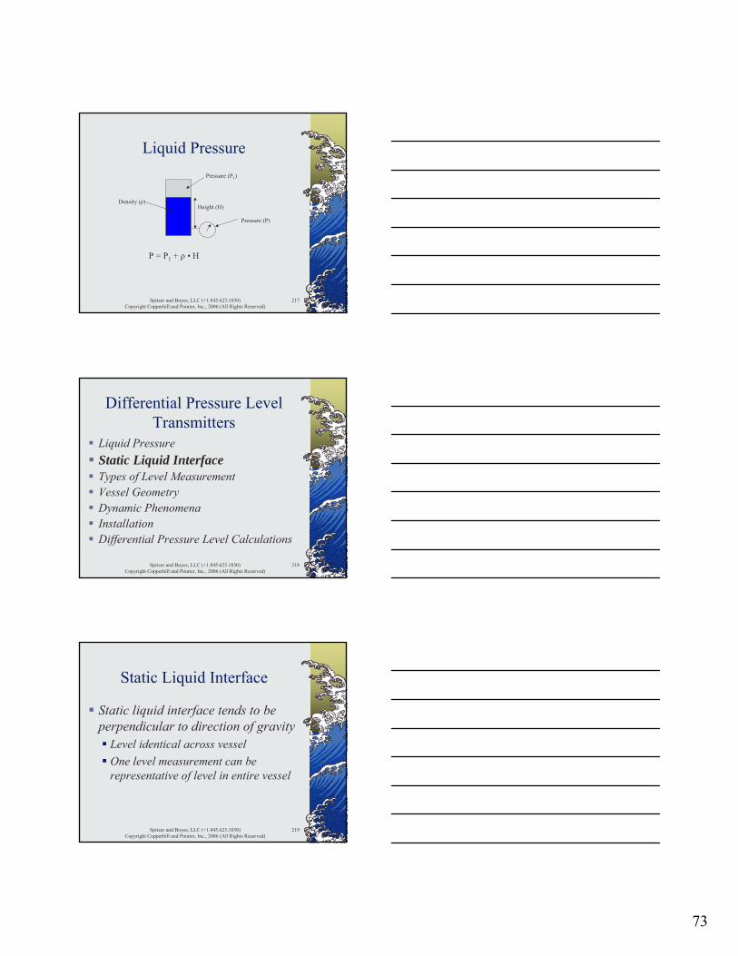
Height (H)
Pressure (P1)
Density (ρ)
Pressure (P)
P = P1 + ρ • H
Spitzer and Boyes, LLC (+1.845.623.1830)Copyright Copperhill and Pointer, Inc., 2006 (All Rights Reserved)
218
Differential Pressure Level Transmitters
Liquid PressureStatic Liquid InterfaceTypes of Level MeasurementVessel GeometryDynamic PhenomenaInstallationDifferential Pressure Level Calculations
Spitzer and Boyes, LLC (+1.845.623.1830)Copyright Copperhill and Pointer, Inc., 2006 (All Rights Reserved)
219
Static Liquid Interface
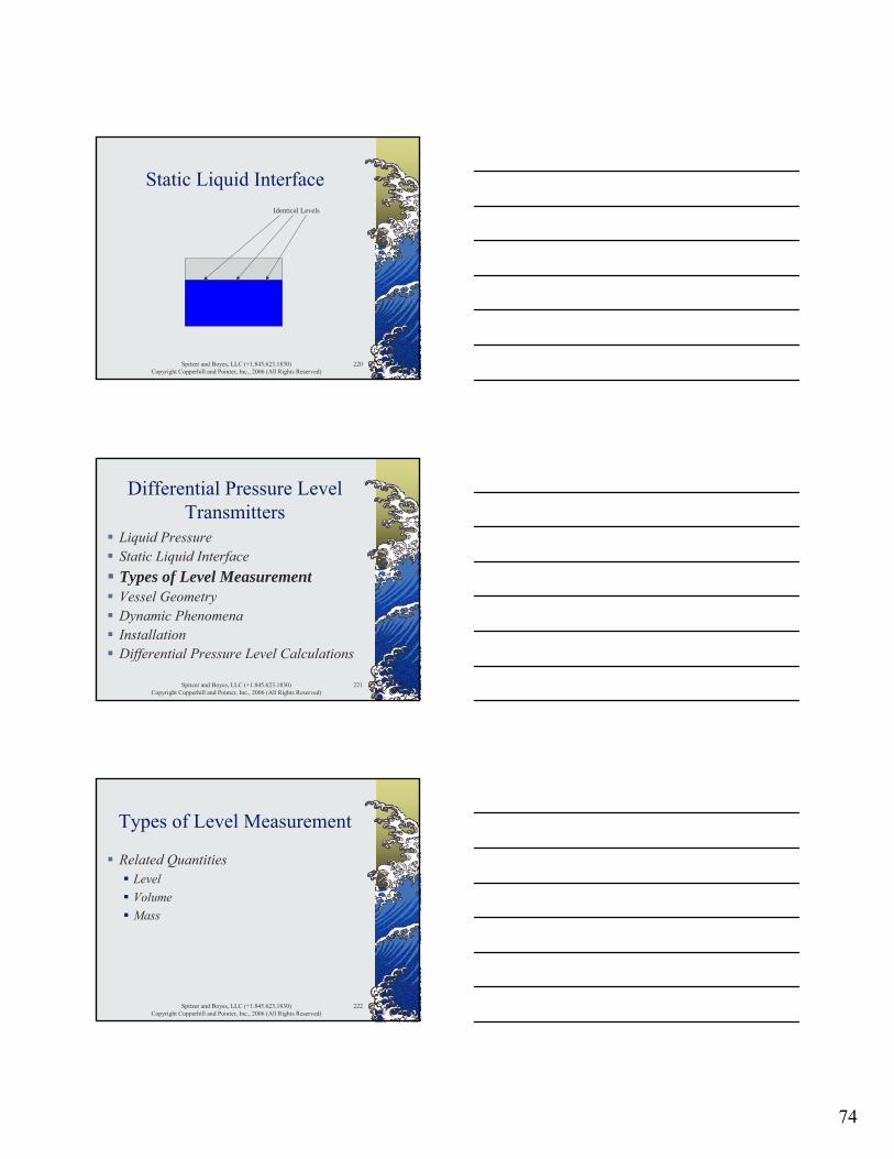
Static liquid interface tends to be perpendicular to direction of gravity
Level identical across vesselOne level measurement can be representative of level in entire vessel
74
Spitzer and Boyes, LLC (+1.845.623.1830)Copyright Copperhill and Pointer, Inc., 2006 (All Rights Reserved)
220
Static Liquid InterfaceIdentical Levels
Spitzer and Boyes, LLC (+1.845.623.1830)Copyright Copperhill and Pointer, Inc., 2006 (All Rights Reserved)
221
Differential Pressure Level Transmitters
Liquid PressureStatic Liquid InterfaceTypes of Level MeasurementVessel GeometryDynamic PhenomenaInstallationDifferential Pressure Level Calculations
Spitzer and Boyes, LLC (+1.845.623.1830)Copyright Copperhill and Pointer, Inc., 2006 (All Rights Reserved)
222
Types of Level Measurement
Related QuantitiesLevelVolumeMass
75
Spitzer and Boyes, LLC (+1.845.623.1830)Copyright Copperhill and Pointer, Inc., 2006 (All Rights Reserved)
223
Types of Level Measurement
m = ρ • V
m massρ density or bulk densityV volume
Spitzer and Boyes, LLC (+1.845.623.1830)Copyright Copperhill and Pointer, Inc., 2006 (All Rights Reserved)
224
Types of Level Measurement
Typical Units (m = ρ • V)lb/ft3 • ft3 = lbkg/m3 • m3 = kg
Spitzer and Boyes, LLC (+1.845.623.1830)Copyright Copperhill and Pointer, Inc., 2006 (All Rights Reserved)
225
Types of Level Measurement
Level measurementHeight of material in vessel
feetmeters
76
Spitzer and Boyes, LLC (+1.845.623.1830)Copyright Copperhill and Pointer, Inc., 2006 (All Rights Reserved)
226
Types of Level Measurement
Inferred volume of material in vesselMeasure levelUse tank geometry to calculate volume
Spitzer and Boyes, LLC (+1.845.623.1830)Copyright Copperhill and Pointer, Inc., 2006 (All Rights Reserved)
227
Types of Level Measurement
Volume of material in vesselRound vertical flat bottom tank
V = ¼ • π • D2 • HDish / coneHorizontal tank
Spitzer and Boyes, LLC (+1.845.623.1830)Copyright Copperhill and Pointer, Inc., 2006 (All Rights Reserved)
228
Types of Level Measurement
ProblemWhat is the inferred volume of liquid in a round vertical flat bottom tank that is 2 meters in diameter when the liquid level is measured to be 4 meters above the bottom?
77
Spitzer and Boyes, LLC (+1.845.623.1830)Copyright Copperhill and Pointer, Inc., 2006 (All Rights Reserved)
229
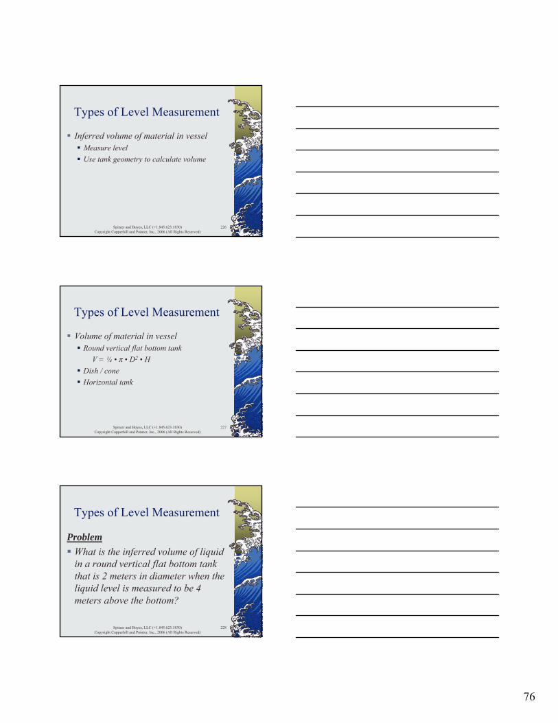
Types of Level Measurement
Level (4m)
Diameter (2m)
Spitzer and Boyes, LLC (+1.845.623.1830)Copyright Copperhill and Pointer, Inc., 2006 (All Rights Reserved)
230
Types of Level Measurement
Calculate the inferred liquid volumeV = ¼ • π • D2 • H
= ¼ • π • 22 • 4= 12.57 m3
Spitzer and Boyes, LLC (+1.845.623.1830)Copyright Copperhill and Pointer, Inc., 2006 (All Rights Reserved)
231
Types of Level Measurement
Inferred level measurementMeasureUse material properties (density / bulk density) to calculate level
H = ΔP / ρ
78
Spitzer and Boyes, LLC (+1.845.623.1830)Copyright Copperhill and Pointer, Inc., 2006 (All Rights Reserved)
232
Types of Level Measurement
ProblemWhat is the level of liquid with a density of 0.9 g/cm3 in a round vertical flat bottom tank that is 2 meters in diameter when the pressure at the bottom of the tank is 4 meters of water column?
Spitzer and Boyes, LLC (+1.845.623.1830)Copyright Copperhill and Pointer, Inc., 2006 (All Rights Reserved)
233
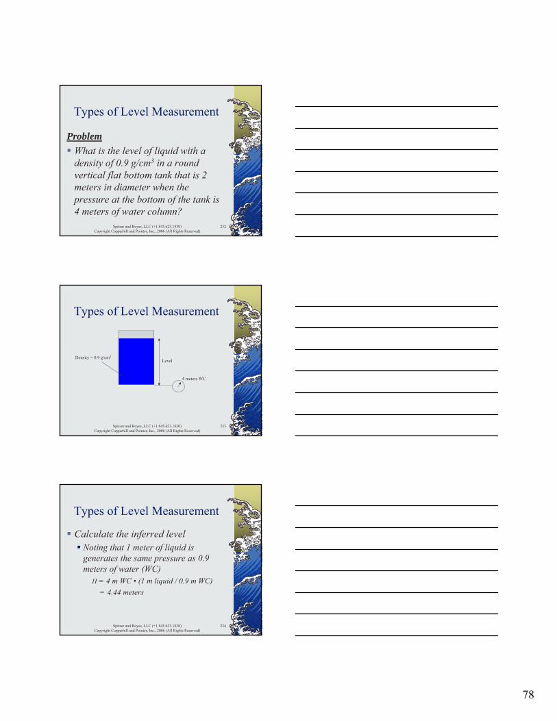
Types of Level Measurement
Level
4 meters WC
Density = 0.9 g/cm3
Spitzer and Boyes, LLC (+1.845.623.1830)Copyright Copperhill and Pointer, Inc., 2006 (All Rights Reserved)
234
Types of Level Measurement
Calculate the inferred levelNoting that 1 meter of liquid is generates the same pressure as 0.9 meters of water (WC)
H = 4 m WC • (1 m liquid / 0.9 m WC)= 4.44 meters

79
Spitzer and Boyes, LLC (+1.845.623.1830)Copyright Copperhill and Pointer, Inc., 2006 (All Rights Reserved)
235
Types of Level Measurement
Mass measurementQuantity (mass) of material in vessel
poundskilograms
Spitzer and Boyes, LLC (+1.845.623.1830)Copyright Copperhill and Pointer, Inc., 2006 (All Rights Reserved)
236
Types of Level Measurement
Inferred volume measurementMeasure mass of materialUse material properties (density / bulk density) to calculate volume
V = m / ρ
Spitzer and Boyes, LLC (+1.845.623.1830)Copyright Copperhill and Pointer, Inc., 2006 (All Rights Reserved)
237
Types of Level Measurement
ProblemWhat is the volume of liquid with a density of 0.9 g/cm3 in a round vertical flat bottom tank that is 2 meters in diameter when the weight of the liquid is 12 MT?

80
Spitzer and Boyes, LLC (+1.845.623.1830)Copyright Copperhill and Pointer, Inc., 2006 (All Rights Reserved)
238
Types of Level Measurement
LevelDensity = 0.9 g/cm3
Spitzer and Boyes, LLC (+1.845.623.1830)Copyright Copperhill and Pointer, Inc., 2006 (All Rights Reserved)
239
Types of Level Measurement
Calculate the volumeV = m / ρ
= 12000 kg / 900 kg/m3
= 13.33 m3
Spitzer and Boyes, LLC (+1.845.623.1830)Copyright Copperhill and Pointer, Inc., 2006 (All Rights Reserved)
240
Types of Level Measurement
Inferred mass measurementMeasure levelUse tank geometry to calculate volumeUse volume and material properties (density / bulk density) to calculate mass
81
Spitzer and Boyes, LLC (+1.845.623.1830)Copyright Copperhill and Pointer, Inc., 2006 (All Rights Reserved)
241
Types of Level Measurement
Inferred mass measurementCalculate volume using tank geometry
Vertical round flat bottom tankV = ¼ • π • D2 • H
Calculate mass using densitym = ρ • V
Spitzer and Boyes, LLC (+1.845.623.1830)Copyright Copperhill and Pointer, Inc., 2006 (All Rights Reserved)
242
Types of Level Measurement
ProblemWhat is the inferred mass of a liquid with a density of 0.9 g/cm3 in a round vertical flat bottom tank that is 2 meters in diameter when the liquid level is measured to be 4 meters above the bottom?
Spitzer and Boyes, LLC (+1.845.623.1830)Copyright Copperhill and Pointer, Inc., 2006 (All Rights Reserved)
243
Types of Level Measurement
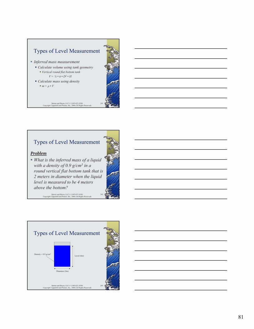
Level (4m)
Diameter (2m)
Density = 0.9 g/cm3

82
Spitzer and Boyes, LLC (+1.845.623.1830)Copyright Copperhill and Pointer, Inc., 2006 (All Rights Reserved)
244
Types of Level Measurement
The inferred liquid volume was previously calculated
V = ¼ • π • D2 • H= ¼ • π • 22 • 4= 12.57 m3
Spitzer and Boyes, LLC (+1.845.623.1830)Copyright Copperhill and Pointer, Inc., 2006 (All Rights Reserved)
245
Types of Level Measurement
Calculate the mass of the liquidm = ρ • V
= 900 kg/m3 • 12.57 m3
= 11313 kg
Spitzer and Boyes, LLC (+1.845.623.1830)Copyright Copperhill and Pointer, Inc., 2006 (All Rights Reserved)
246
Types of Level Measurement
Level and mass measurements are subject to uncertaintyInferred measurements are subject to additional uncertainty
DensityGeometry

83
Spitzer and Boyes, LLC (+1.845.623.1830)Copyright Copperhill and Pointer, Inc., 2006 (All Rights Reserved)
247
Differential Pressure Level Transmitters
Liquid PressureStatic Liquid InterfaceTypes of Level MeasurementVessel GeometryDynamic PhenomenaInstallationDifferential Pressure Level Calculations
Spitzer and Boyes, LLC (+1.845.623.1830)Copyright Copperhill and Pointer, Inc., 2006 (All Rights Reserved)
248
Vessel Geometry
The inside vessel dimensions are important for inferring volume/mass
Drawings often show outside dimensions
Wall thickness
Spitzer and Boyes, LLC (+1.845.623.1830)Copyright Copperhill and Pointer, Inc., 2006 (All Rights Reserved)
249
Vessel Geometry
Drawings often state nominal tank volume
Calculations based upon actual dimensions will likely be different
84
Spitzer and Boyes, LLC (+1.845.623.1830)Copyright Copperhill and Pointer, Inc., 2006 (All Rights Reserved)
250
Vessel Geometry
Inferred (level and mass) measurements should take into account:
Unmeasured volumeDish / cone volumeVessel orientation
Spitzer and Boyes, LLC (+1.845.623.1830)Copyright Copperhill and Pointer, Inc., 2006 (All Rights Reserved)
251
Vessel Geometry
Dish
Height (H)
UnmeasuredHeight
Vertical Tank with Dish
Spitzer and Boyes, LLC (+1.845.623.1830)Copyright Copperhill and Pointer, Inc., 2006 (All Rights Reserved)
252
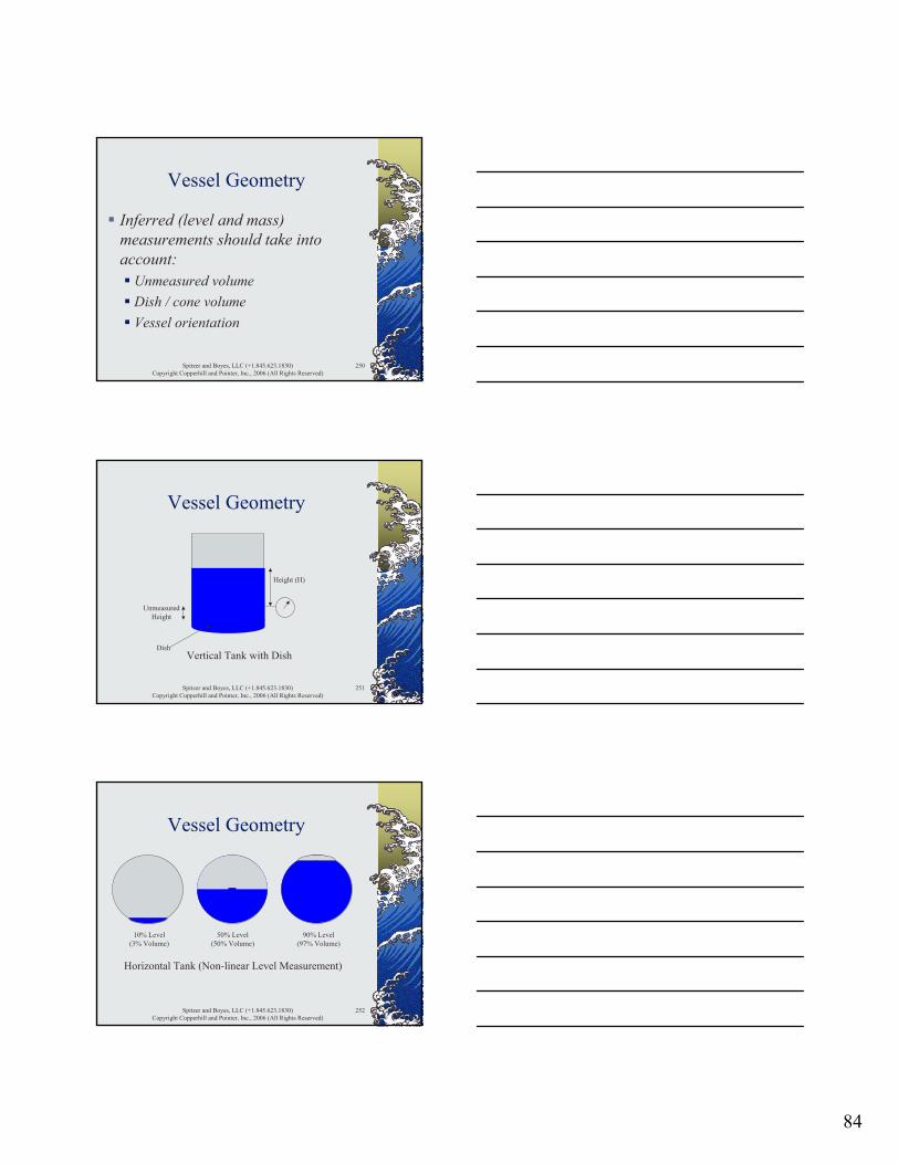
Vessel Geometry
50% Level(50% Volume)
10% Level(3% Volume)
90% Level(97% Volume)
Horizontal Tank (Non-linear Level Measurement)
85
Spitzer and Boyes, LLC (+1.845.623.1830)Copyright Copperhill and Pointer, Inc., 2006 (All Rights Reserved)
253
Vessel Geometry
A reference location (datum) should be determined based upon
Sensing technologySensor locationVessel geometry
Spitzer and Boyes, LLC (+1.845.623.1830)Copyright Copperhill and Pointer, Inc., 2006 (All Rights Reserved)
254
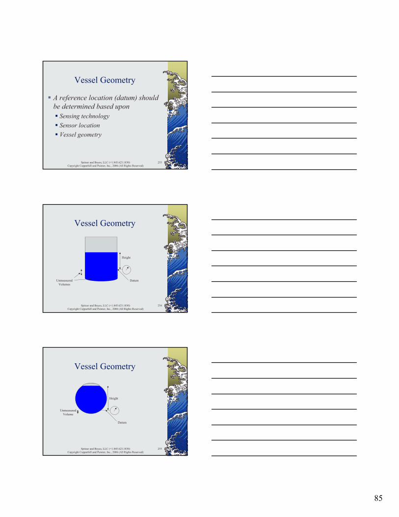
Vessel Geometry
Height
DatumUnmeasuredVolumes
Spitzer and Boyes, LLC (+1.845.623.1830)Copyright Copperhill and Pointer, Inc., 2006 (All Rights Reserved)
255
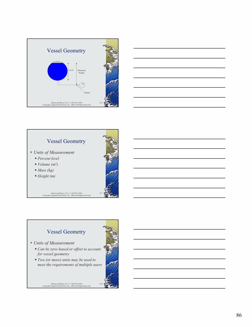
Vessel Geometry
Datum
Height
UnmeasuredVolume
86
Spitzer and Boyes, LLC (+1.845.623.1830)Copyright Copperhill and Pointer, Inc., 2006 (All Rights Reserved)
256
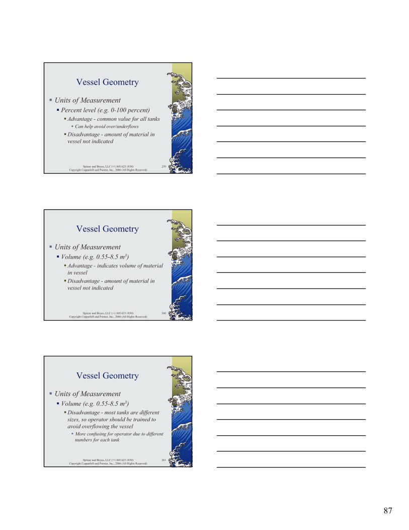
Vessel Geometry
Datum
MeasuredHeight
Level
Spitzer and Boyes, LLC (+1.845.623.1830)Copyright Copperhill and Pointer, Inc., 2006 (All Rights Reserved)
257
Vessel Geometry
Units of MeasurementPercent levelVolume (m3)Mass (kg)Height (m)
Spitzer and Boyes, LLC (+1.845.623.1830)Copyright Copperhill and Pointer, Inc., 2006 (All Rights Reserved)
258
Vessel Geometry
Units of MeasurementCan be zero-based or offset to account for vessel geometryTwo (or more) units may be used to meet the requirements of multiple users
87
Spitzer and Boyes, LLC (+1.845.623.1830)Copyright Copperhill and Pointer, Inc., 2006 (All Rights Reserved)
259
Vessel Geometry
Units of MeasurementPercent level (e.g. 0-100 percent)
Advantage - common value for all tanksCan help avoid over/underflows
Disadvantage - amount of material in vessel not indicated
Spitzer and Boyes, LLC (+1.845.623.1830)Copyright Copperhill and Pointer, Inc., 2006 (All Rights Reserved)
260
Vessel Geometry
Units of MeasurementVolume (e.g. 0.55-8.5 m3)
Advantage - indicates volume of material in vesselDisadvantage - amount of material in vessel not indicated
Spitzer and Boyes, LLC (+1.845.623.1830)Copyright Copperhill and Pointer, Inc., 2006 (All Rights Reserved)
261
Vessel Geometry
Units of MeasurementVolume (e.g. 0.55-8.5 m3)
Disadvantage - most tanks are different sizes, so operator should be trained to avoid overflowing the vessel
More confusing for operator due to different numbers for each tank
88
Spitzer and Boyes, LLC (+1.845.623.1830)Copyright Copperhill and Pointer, Inc., 2006 (All Rights Reserved)
262
Vessel Geometry
Units of MeasurementMass (e.g. 550-8500 kg)
Advantage - indicates amount of material in vessel
Spitzer and Boyes, LLC (+1.845.623.1830)Copyright Copperhill and Pointer, Inc., 2006 (All Rights Reserved)
263
Vessel Geometry
Units of MeasurementMass (e.g. 550-8500 kg)
Disadvantage - most tanks are different sizes, so operator should be trained to avoid overflowing the vessel
More confusing for operator due to different numbers for each tank
Spitzer and Boyes, LLC (+1.845.623.1830)Copyright Copperhill and Pointer, Inc., 2006 (All Rights Reserved)
264
Vessel Geometry
Units of MeasurementHeight (e.g. 0-10 meters)
Advantage - indicates actual levelDisadvantage - amount of material in vessel not indicated
89
Spitzer and Boyes, LLC (+1.845.623.1830)Copyright Copperhill and Pointer, Inc., 2006 (All Rights Reserved)
265
Vessel Geometry
Units of MeasurementMass (e.g. 0-10 meters)
Disadvantage - most tanks are different heights, so operator should be trained to avoid overflowing the vessel
More confusing for operator due to different heights for each tank
Spitzer and Boyes, LLC (+1.845.623.1830)Copyright Copperhill and Pointer, Inc., 2006 (All Rights Reserved)
266
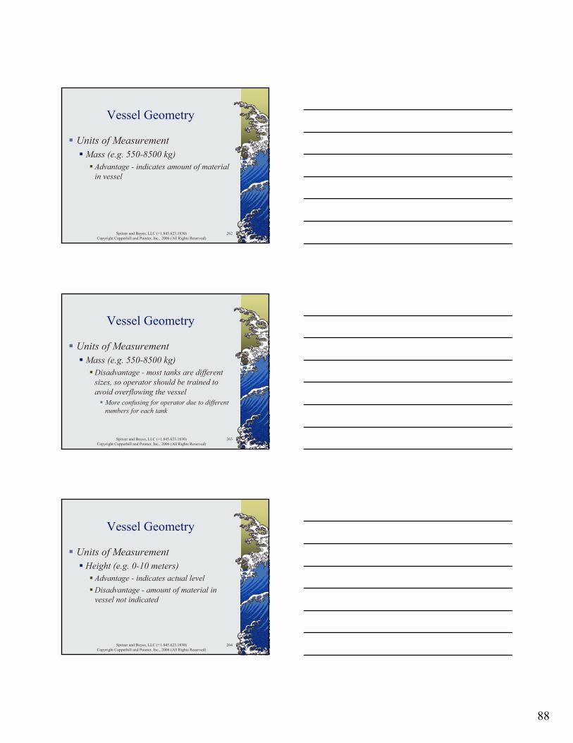
Vessel Geometry
0 mA
0 %
Signal
16 mA
20 mA
4 mA
100 %
75 %
Signal
12 %
Fill
100 %
88 %
120
Kg
1000
880
160
Kg (with dish)
1040
920
Spitzer and Boyes, LLC (+1.845.623.1830)Copyright Copperhill and Pointer, Inc., 2006 (All Rights Reserved)
267
Differential Pressure Level Transmitters
Liquid PressureStatic Liquid InterfaceTypes of Level MeasurementVessel GeometryDynamic PhenomenaInstallationDifferential Pressure Level Calculations
90
Spitzer and Boyes, LLC (+1.845.623.1830)Copyright Copperhill and Pointer, Inc., 2006 (All Rights Reserved)
268
Dynamic Phenomena - Foam
Foam
Spitzer and Boyes, LLC (+1.845.623.1830)Copyright Copperhill and Pointer, Inc., 2006 (All Rights Reserved)
269
Dynamic Phenomena - Foam
FoamFill
Spitzer and Boyes, LLC (+1.845.623.1830)Copyright Copperhill and Pointer, Inc., 2006 (All Rights Reserved)
270
Dynamic Phenomena - Foam
Reducing foamDe-foaming additivesSubmerged fill can sometimes reduce formation of foam

91
Spitzer and Boyes, LLC (+1.845.623.1830)Copyright Copperhill and Pointer, Inc., 2006 (All Rights Reserved)
271
Dynamic Phenomena - Foam
Reduced Amountof Foam
Fill
Spitzer and Boyes, LLC (+1.845.623.1830)Copyright Copperhill and Pointer, Inc., 2006 (All Rights Reserved)
272
Dynamic Phenomena - Foam
Foam
Liquid withHigh Vapor Pressure
Spitzer and Boyes, LLC (+1.845.623.1830)Copyright Copperhill and Pointer, Inc., 2006 (All Rights Reserved)
273
Dynamic Phenomena - Foam
Reduced Foam
Liquid withHigh Vapor Pressure
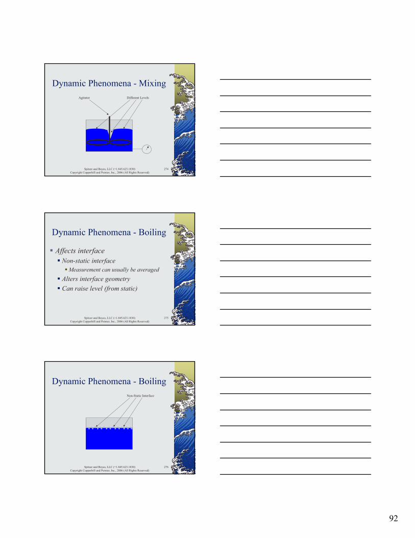
92
Spitzer and Boyes, LLC (+1.845.623.1830)Copyright Copperhill and Pointer, Inc., 2006 (All Rights Reserved)
274
Dynamic Phenomena - MixingDifferent LevelsAgitator
Spitzer and Boyes, LLC (+1.845.623.1830)Copyright Copperhill and Pointer, Inc., 2006 (All Rights Reserved)
275
Dynamic Phenomena - Boiling
Affects interfaceNon-static interface
Measurement can usually be averagedAlters interface geometryCan raise level (from static)
Spitzer and Boyes, LLC (+1.845.623.1830)Copyright Copperhill and Pointer, Inc., 2006 (All Rights Reserved)
276
Dynamic Phenomena - BoilingNon-Static Interface
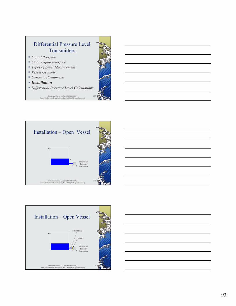
93
Spitzer and Boyes, LLC (+1.845.623.1830)Copyright Copperhill and Pointer, Inc., 2006 (All Rights Reserved)
277
Differential Pressure Level Transmitters
Liquid PressureStatic Liquid InterfaceTypes of Level MeasurementVessel GeometryDynamic PhenomenaInstallationDifferential Pressure Level Calculations
Spitzer and Boyes, LLC (+1.845.623.1830)Copyright Copperhill and Pointer, Inc., 2006 (All Rights Reserved)
278
Installation – Open Vessel
H
DifferentialPressure
TransmitterL
Spitzer and Boyes, LLC (+1.845.623.1830)Copyright Copperhill and Pointer, Inc., 2006 (All Rights Reserved)
279
Installation – Open Vessel
H
DifferentialPressure
TransmitterL
Flange
Filler Flange
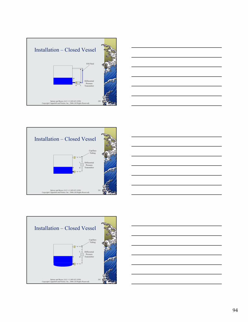
94
Spitzer and Boyes, LLC (+1.845.623.1830)Copyright Copperhill and Pointer, Inc., 2006 (All Rights Reserved)
280
Installation – Closed Vessel
H
DifferentialPressure
TransmitterL
Fill Fluid
Spitzer and Boyes, LLC (+1.845.623.1830)Copyright Copperhill and Pointer, Inc., 2006 (All Rights Reserved)
281
Installation – Closed Vessel
H
DifferentialPressure
Transmitter
L
x
xx
x
x xxx
CapillaryTubing
Spitzer and Boyes, LLC (+1.845.623.1830)Copyright Copperhill and Pointer, Inc., 2006 (All Rights Reserved)
282
Installation – Closed Vessel
H
DifferentialPressure
Transmitter
L
x
xxx
x xxx
CapillaryTubing
x
x
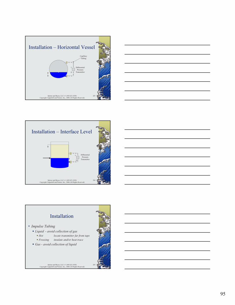
95
Spitzer and Boyes, LLC (+1.845.623.1830)Copyright Copperhill and Pointer, Inc., 2006 (All Rights Reserved)
283
Installation – Horizontal Vessel
H
DifferentialPressure
Transmitter
L
x
xx
x
x xxx
CapillaryTubing
Spitzer and Boyes, LLC (+1.845.623.1830)Copyright Copperhill and Pointer, Inc., 2006 (All Rights Reserved)
284
Installation – Interface Level
H
DifferentialPressure
Transmitter
Lx xx
x xx
Spitzer and Boyes, LLC (+1.845.623.1830)Copyright Copperhill and Pointer, Inc., 2006 (All Rights Reserved)
285
Installation
Impulse TubingLiquid - avoid collection of gas
Hot locate transmitter far from tapsFreezing insulate and/or heat trace
Gas - avoid collection of liquid

96
Spitzer and Boyes, LLC (+1.845.623.1830)Copyright Copperhill and Pointer, Inc., 2006 (All Rights Reserved)
286
Differential Pressure Level Transmitters
Liquid PressureStatic Liquid InterfaceTypes of Level MeasurementVessel GeometryDynamic PhenomenaInstallationDifferential Pressure Level Calculations
Spitzer and Boyes, LLC (+1.845.623.1830)Copyright Copperhill and Pointer, Inc., 2006 (All Rights Reserved)
287
Differential Pressure Level Classroom Exercise 1
A vertical cylindrical tank is 10 meters high with a diameter of 3 meters. The tank contains water that overflows 9 meters above its flat bottom. A differential pressure level transmitter is mounted on a tap located 1 meter above the bottom of the tank. Calculate the calibration of the differential pressure level transmitter.
Spitzer and Boyes, LLC (+1.845.623.1830)Copyright Copperhill and Pointer, Inc., 2006 (All Rights Reserved)
288
Differential Pressure Level Classroom Exercise 2
A vertical cylindrical tank rated for 4 bar of pressure and full vacuum is 6 m high. The tank has a diameter of 2 meters and contains a liquid with a specific gravity of 0.95. A differential pressure level transmitter is mounted on a tap located 0.50 meters above the lower tangent line of the tank. The low-pressure nozzle is located 0.50 meters below the upper tangent line of the tank and has a fill fluid with a specific gravity of 1.05. Calculate the calibration of the differential pressure level transmitter.
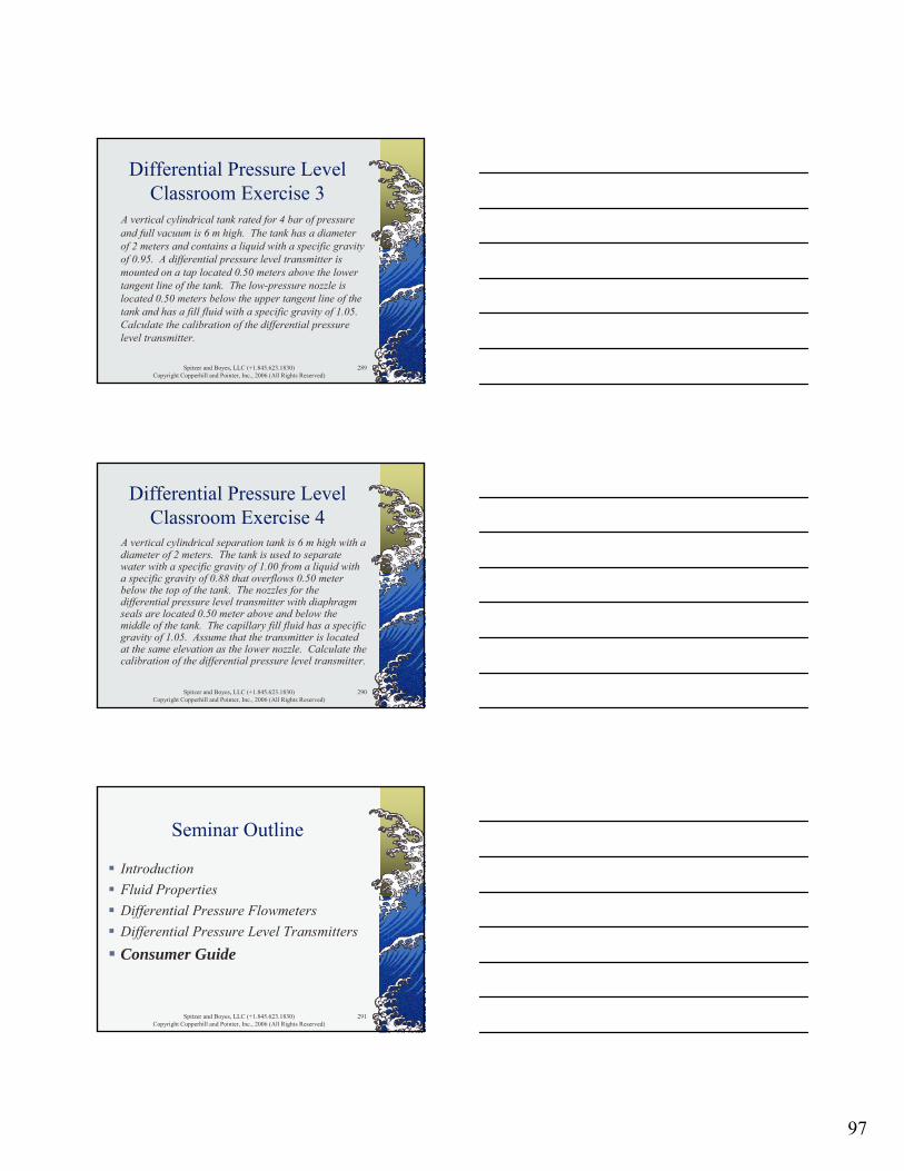
97
Spitzer and Boyes, LLC (+1.845.623.1830)Copyright Copperhill and Pointer, Inc., 2006 (All Rights Reserved)
289
Differential Pressure Level Classroom Exercise 3
A vertical cylindrical tank rated for 4 bar of pressure and full vacuum is 6 m high. The tank has a diameter of 2 meters and contains a liquid with a specific gravity of 0.95. A differential pressure level transmitter is mounted on a tap located 0.50 meters above the lower tangent line of the tank. The low-pressure nozzle is located 0.50 meters below the upper tangent line of the tank and has a fill fluid with a specific gravity of 1.05. Calculate the calibration of the differential pressure level transmitter.
Spitzer and Boyes, LLC (+1.845.623.1830)Copyright Copperhill and Pointer, Inc., 2006 (All Rights Reserved)
290
Differential Pressure Level Classroom Exercise 4
A vertical cylindrical separation tank is 6 m high with a diameter of 2 meters. The tank is used to separate water with a specific gravity of 1.00 from a liquid with a specific gravity of 0.88 that overflows 0.50 meter below the top of the tank. The nozzles for the differential pressure level transmitter with diaphragm seals are located 0.50 meter above and below the middle of the tank. The capillary fill fluid has a specific gravity of 1.05. Assume that the transmitter is located at the same elevation as the lower nozzle. Calculate the calibration of the differential pressure level transmitter.
Spitzer and Boyes, LLC (+1.845.623.1830)Copyright Copperhill and Pointer, Inc., 2006 (All Rights Reserved)
291
Seminar Outline
IntroductionFluid PropertiesDifferential Pressure FlowmetersDifferential Pressure Level TransmittersConsumer Guide

98
Spitzer and Boyes, LLC (+1.845.623.1830)Copyright Copperhill and Pointer, Inc., 2006 (All Rights Reserved)
292
Consumer Guide
User Equipment Selection ProcessLearn about the technologyFind suitable vendorsObtain specificationsOrganize specificationsEvaluate specificationsSelect equipment
Spitzer and Boyes, LLC (+1.845.623.1830)Copyright Copperhill and Pointer, Inc., 2006 (All Rights Reserved)
293
Consumer Guide
User Equipment Selection ProcessPerforming this process takes time and therefore costs money
Spitzer and Boyes, LLC (+1.845.623.1830)Copyright Copperhill and Pointer, Inc., 2006 (All Rights Reserved)
294
Consumer Guide
User Equipment Selection ProcessHaphazard implementation with limited knowledge of alternatives does not necessarily lead to a good equipment selection

99
Spitzer and Boyes, LLC (+1.845.623.1830)Copyright Copperhill and Pointer, Inc., 2006 (All Rights Reserved)
295
Consumer Guide
Guide Provides First Four ItemsLearn about the technologyFind suitable vendorsObtain specificationsOrganize specificationsEvaluate specificationsSelect equipment
Spitzer and Boyes, LLC (+1.845.623.1830)Copyright Copperhill and Pointer, Inc., 2006 (All Rights Reserved)
296
Consumer Guide
Guide Provides First Four ItemsInformation focused on technologyComprehensive lists of suppliers and equipment
Spitzer and Boyes, LLC (+1.845.623.1830)Copyright Copperhill and Pointer, Inc., 2006 (All Rights Reserved)
297
Consumer Guide
Guide Provides First Four ItemsSignificant specificationsLists of equipment organized to facilitate evaluation
100
Spitzer and Boyes, LLC (+1.845.623.1830)Copyright Copperhill and Pointer, Inc., 2006 (All Rights Reserved)
298
Consumer Guide
User Equipment Selection ProcessBy providing the first four items, the Consumer Guides:
make technical evaluation and equipment selection easier, more comprehensive, and more efficient
Spitzer and Boyes, LLC (+1.845.623.1830)Copyright Copperhill and Pointer, Inc., 2006 (All Rights Reserved)
299
Consumer Guide
User Equipment Selection ProcessBy providing the first four items, the Consumer Guides:
allow selection from a larger number of supplierssimplifies the overall selection process
Spitzer and Boyes, LLC (+1.845.623.1830)Copyright Copperhill and Pointer, Inc., 2006 (All Rights Reserved)
300
Consumer Guide
Supplier Data and AnalysisAttachments
Flowmeter categoriesAvailability of selected featuresModels grouped by performance

101
Spitzer and Boyes, LLC (+1.845.623.1830)Copyright Copperhill and Pointer, Inc., 2006 (All Rights Reserved)
301
Review and Questions
IntroductionFluid PropertiesDifferential Pressure FlowmetersDifferential Pressure Level TransmittersConsumer Guide
Spitzer and Boyes, LLC (+1.845.623.1830)Copyright Copperhill and Pointer, Inc., 2006 (All Rights Reserved)
302
Differential Pressure Level Classroom Exercise 1
Empty Tank H = 0 mL = 0 mΔP = H-L = 0-0 = 0 m
Full Tank H = (9-1)●1.0 = 8 mL = 0 mΔP = H-L = 8-0 = 8 m
Calibration: 0 to 8 meters WC
Spitzer and Boyes, LLC (+1.845.623.1830)Copyright Copperhill and Pointer, Inc., 2006 (All Rights Reserved)
303
Differential Pressure Level Classroom Exercise 2
Empty Tank H = 0 mL = (5.50-0.50) ● 1.05 = 5.25 mΔP = H-L = 0-5.25 = -5.25 m
Full Tank H = (5.50-0.50) ● 0.95 = 4.75 mL = (5.50-0.50) ● 1.05 = 5.25 mΔP = H-L = 4.75-5.25 = -0.50 m
Calibration: -5.25 to -0.50 meters WC
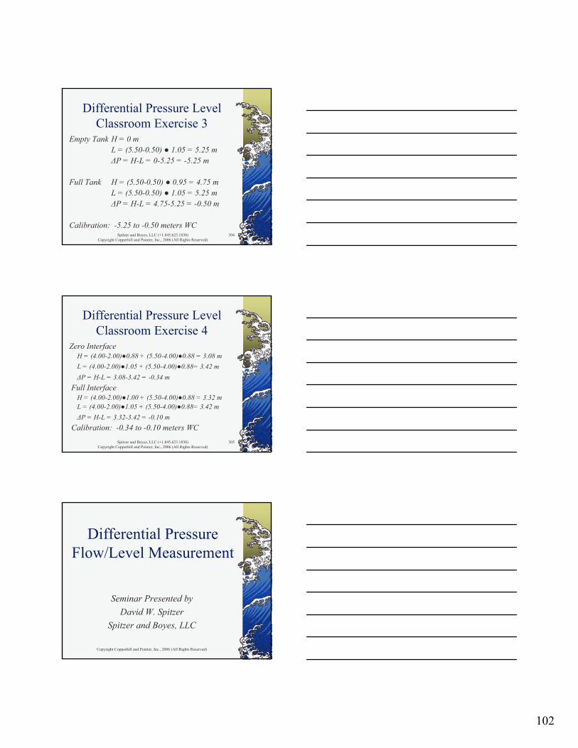
102
Spitzer and Boyes, LLC (+1.845.623.1830)Copyright Copperhill and Pointer, Inc., 2006 (All Rights Reserved)
304
Differential Pressure Level Classroom Exercise 3
Empty Tank H = 0 mL = (5.50-0.50) ● 1.05 = 5.25 mΔP = H-L = 0-5.25 = -5.25 m
Full Tank H = (5.50-0.50) ● 0.95 = 4.75 mL = (5.50-0.50) ● 1.05 = 5.25 mΔP = H-L = 4.75-5.25 = -0.50 m
Calibration: -5.25 to -0.50 meters WC
Spitzer and Boyes, LLC (+1.845.623.1830)Copyright Copperhill and Pointer, Inc., 2006 (All Rights Reserved)
305
Differential Pressure Level Classroom Exercise 4
Zero InterfaceH = (4.00-2.00)●0.88 + (5.50-4.00)●0.88 = 3.08 mL = (4.00-2.00)●1.05 + (5.50-4.00)●0.88= 3.42 mΔP = H-L = 3.08-3.42 = -0.34 m
Full InterfaceH = (4.00-2.00)●1.00 + (5.50-4.00)●0.88 = 3.32 mL = (4.00-2.00)●1.05 + (5.50-4.00)●0.88= 3.42 mΔP = H-L = 3.32-3.42 = -0.10 m
Calibration: -0.34 to -0.10 meters WC
Copyright Copperhill and Pointer, Inc., 2006 (All Rights Reserved)
Differential Pressure Flow/Level Measurement
Seminar Presented by David W. Spitzer
Spitzer and Boyes, LLC