Embed Size (px)
Citation preview

WCS1400D6S
DIESEL GENERATING SETS
Your Partner for Power…NOISE LEVEL: N/A
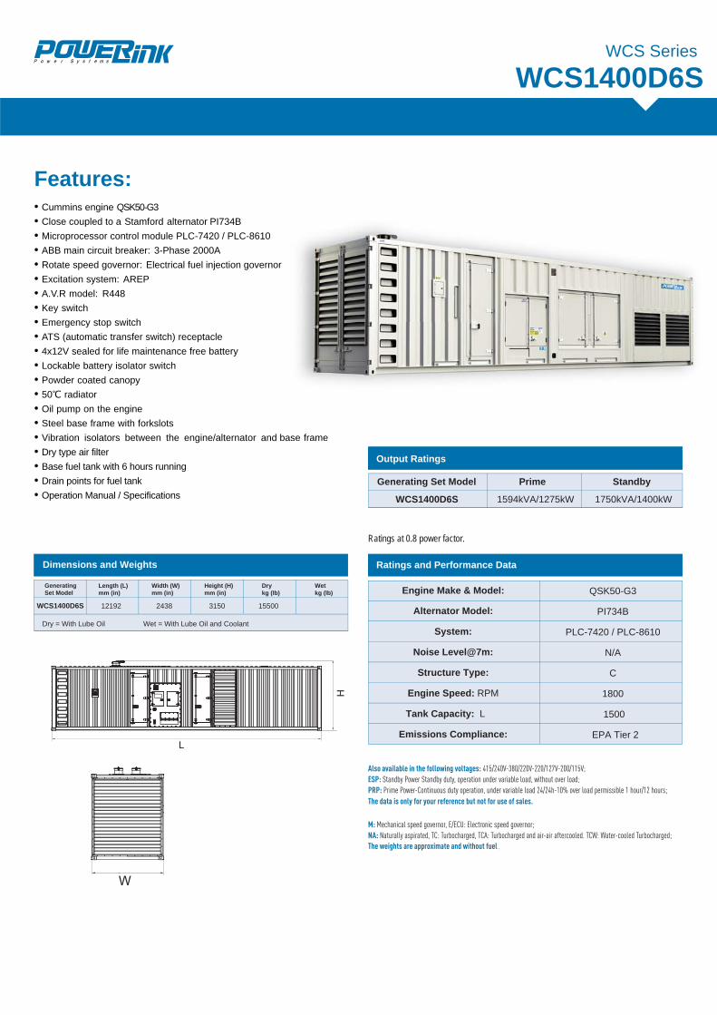
Ratings at 0.8 power factor.
WCS1400D6SWCS Series
Also available in the following voltages: 415/240V-380/220V-220/127V-200/115V; ESP: Standby Power Standby duty, operation under variable load, without over load;PRP: Prime Power-Continuous duty operation, under variable load 24/24h-10% over load permissible 1 hour/12 hours;
M: Mechanical speed governor, E/ECU: Electronic speed governor;NA: Naturally aspirated, TC: Turbocharged, TCA: Turbocharged and air-air aftercooled. TCW: Water-cooled Turbocharged;The weights are approximate and without fuel.
The data is only for your reference but not for use of sales.
Dimensions and Weights
Dry = With Lube Oil Wet = With Lube Oil and Coolant
Length (L)mm (in)
Width (W)mm (in)
Height (H)mm (in)
Drykg (lb)
Wetkg (lb)
GeneratingSet Model
WCS1400D6S
Generating Set Model Prime Standby
WCS1400D6S 1594kVA/1275kW 1750kVA/1400kW
Output Ratings
Ratings and Performance Data
QSK50-G3
PI734B
PLC-7420 / PLC-8610
1800
N/A
C
Engine Make & Model:
Alternator Model:
System:
Noise Level@7m:
Structure Type:
Engine Speed: RPM
Tank Capacity: L 1500
Emissions Compliance: EPA Tier 2
12192 2438 3150 15500
Features:• Cummins engine QSK50-G3• Close coupled to a Stamford alternator PI734B• Microprocessor control module PLC-7420 / PLC-8610• ABB main circuit breaker: 3-Phase 2000A• Rotate speed governor: Electrical fuel injection governor• Excitation system: AREP• A.V.R model: R448• Key switch• Emergency stop switch• ATS (automatic transfer switch) receptacle• 4x12V sealed for life maintenance free battery• Lockable battery isolator switch• Powder coated canopy• 50℃ radiator• Oil pump on the engine• Steel base frame with forkslots• Vibration isolators between the engine/alternator and base frame• Dry type air filter• Base fuel tank with 6 hours running• Drain points for fuel tank• Operation Manual / Specifications
se frame
05
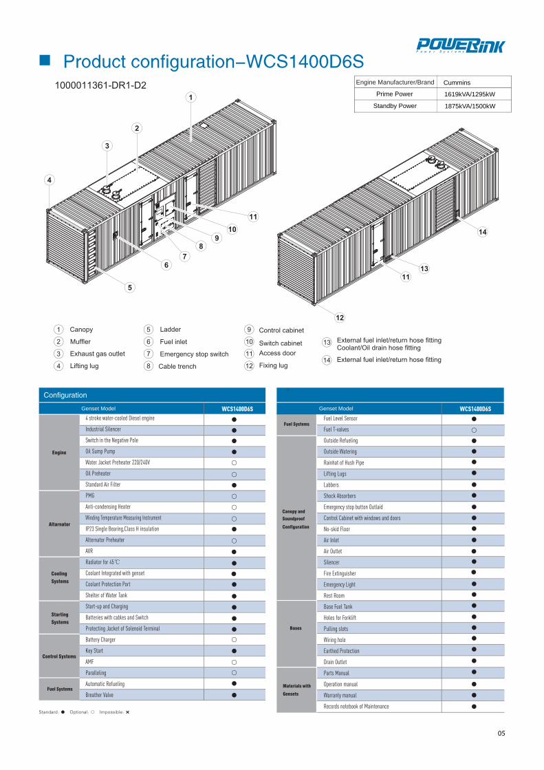
Product configuration-WCS1400D6S
WCS1400D6S WCS1400D6SGenset Model Genset Model
Fuel Level Sensor
Fuel T-valves
Outside Refueling
Outside Watering
Rainhat of Hush Pipe
Lifting Lugs
Labbers
Shock Absorbers
Emergency stop button Outlaid
Control Cabinet with windows and doors
No-skid Floor
Air Inlet
Air Outlet
Silencer
Fire Extinguisher
Emergency Light
Rest Room
Base Fuel Tank
Holes for Forklift
Pulling slots
Wiring hole
Earthed Protection
Drain Outlet
Parts Manual
Operation manual
Warranty manual
Records notebook of Maintenance
4 stroke water-cooled Diesel engine
Industrial Silencer
Switch in the Negative Pole
Oil Sump Pump
Water Jacket Preheater 220/240V
Oil Preheater
Standard Air Filter
PMG
Anti-condensing Heater
Winding Temperature Measuring Instrument
IP23 Single Bearing,Class H insulation
Alternator Preheater
AVR
Radiator for 45℃
Coolant Integrated with genset
Coolant Protection Port
Shelter of Water Tank
Start-up and Charging
Batteries with cables and Switch
Protecting Jacket of Solenoid Terminal
Battery Charger
Key Start
AMF
Paralleling
Automatic Refueling
Breather Valve
Engine Manufacturer/Brand Cummins
Prime Power
Standby Power
1619kVA/1295kW
1875kVA/1500kW
08
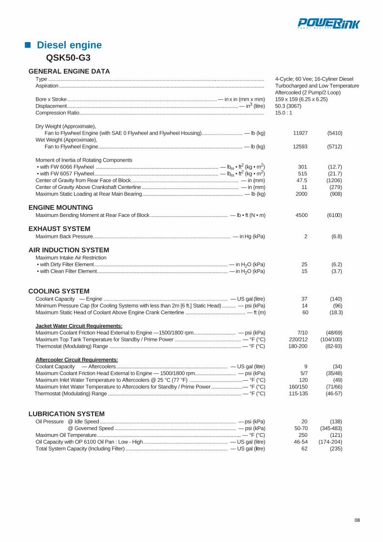
Diesel engineQSK50-G3
GENERAL ENGINE DATAType ............................................................................................................................................................... 4-Cycle; 60 Vee; 16-Cyliner DieselAspiration ....................................................................................................................................................... Turbocharged and Low Temperature
Aftercooled (2 Pump/2 Loop)Bore x Stroke.............................................................................................................. — in x in (mm x mm) 159 x 159 (6.25 x 6.25)Displacement.............................................................................................................................. — in3 (litre) 50.3 (3067)Compression Ratio........................................................................................................................................ 15.0 : 1
Dry Weight (Approximate), Fan to Flywheel Engine (with SAE 0 Flywheel and Flywheel Housing).............................. — lb (kg) 11927 (5410)
Wet Weight (Approximate), Fan to Flywheel Engine.......................................................................................................... — lb (kg) 12593 (5712)
Moment of Inertia of Rotating Components • with FW 6066 Flywheel .......................................................................................... — lbm • ft2 (kg • m2) 301 (12.7) • with FW 6057 Flywheel........................................................................................... — lbm • ft2 (kg • m2) 515 (21.7)Center of Gravity from Rear Face of Block............................................................................... — in (mm) 47.5 (1206)Center of Gravity Above Crankshaft Centerline ....................................................................... — in (mm) 11 (279)Maximum Static Loading at Rear Main Bearing.......................................................................... — lb (kg) 2000 (908)
ENGINE MOUNTINGMaximum Bending Moment at Rear Face of Block ......................................................... — lb • ft (N • m) 4500 (6100)
EXHAUST SYSTEMMaximum Back Pressure..................................................................................................... — in Hg (kPa) 2 (6.8)
AIR INDUCTION SYSTEMMaximum Intake Air Restriction • with Dirty Filter Element.................................................................................................. — in H2O (kPa) 25 (6.2) • with Clean Filter Element................................................................................................ — in H2O (kPa) 15 (3.7)
COOLING SYSTEMCoolant Capacity — Engine ........................................................................................... — US gal (litre) 37 (140)Minimum Pressure Cap (for Cooling Systems with less than 2m [6 ft.] Static Head) .......... — psi (kPa) 14 (96)Maximum Static Head of Coolant Above Engine Crank Centerline ............................................ — ft (m) 60 (18.3)
Jacket Water Circuit Requirements:Maximum Coolant Friction Head External to Engine —1500/1800 rpm............................... — psi (kPa) 7/10 (48/69)Maximum Top Tank Temperature for Standby / Prime Power ................................................. — °F (°C) 220/212 (104/100)Thermostat (Modulating) Range ................................................................................................. — °F (°C) 180-200 (82-93)
Aftercooler Circuit Requirements:Coolant Capacity — Aftercoolers.................................................................................. — US gal (litre) 9 (34)Maximum Coolant Friction Head External to Engine — 1500/1800 rpm.............................. — psi (kPa) 5/7 (35/48)Maximum Inlet Water Temperature to Aftercoolers @ 25 °C (77 °F) .......................................— °F (°C) 120 (49)Maximum Inlet Water Temperature to Aftercoolers for Standby / Prime Power.......................— °F (°C) 160/150 (71/66)Thermostat (Modulating) Range .................................................................................................. — °F (°C) 115-135 (46-57)
LUBRICATION SYSTEMOil Pressure @ Idle Speed.................................................................................................... — psi (kPa) 20 (138)
@ Governed Speed ......................................................................................... — psi (kPa) 50-70 (345-483)Maximum Oil Temperature.......................................................................................................... — °F (°C) 250 (121)Oil Capacity with OP 6100 Oil Pan : Low - High.............................................................. — US gal (litre) 46-54 (174-204)Total System Capacity (Including Filter) ........................................................................... — US gal (litre) 62 (235)
09
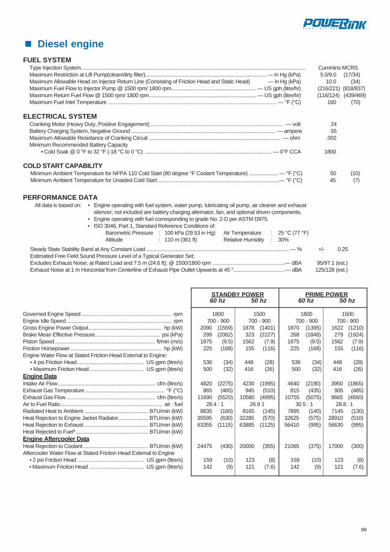
Diesel engineFUEL SYSTEM
Type Injection System.................................................................................................................................................................. Cummins MCRSMaximum Restriction at Lift Pump(clean/dirty filter)........................................................................................— in Hg (kPa) 5.0/9.0 (17/34)Maximum Allowable Head on Injector Return Line (Consisting of Friction Head and Static Head) — in Hg (kPa) 10.0 (34)Maximum Fuel Flow to Injector Pump @ 1500 rpm/ 1800 rpm............................................................. — US gph (litre/hr) (216/221) (818/837)Maximum Return Fuel Flow @ 1500 rpm/ 1800 rpm.............................................................................. — US gph (litre/hr) (116/124) (439/469)Maximum Fuel Inlet Temperature .......................................................................................................................... — °F (°C) 160 (70)
ELECTRICAL SYSTEMCranking Motor (Heavy Duty, Positive Engagement) ................................................................................................ — volt 24Battery Charging System, Negative Ground ........................................................................................................ — ampere 55Maximum Allowable Resistance of Cranking Circuit ............................................................................................... — ohm .002Minimum Recommended Battery Capacity
• Cold Soak @ 0 °F to 32 °F (-18 °C to 0 °C) ............................................................................................— 0°F CCA 1800
COLD START CAPABILITYMinimum Ambient Temperature for NFPA 110 Cold Start (90 degree °F Coolant Temperature) ..................... — °F (°C) 50 (10)Minimum Ambient Temperature for Unaided Cold Start ........................................................................................— °F (°C) 45 (7)
PERFORMANCE DATAAll data is based on: • Engine operating with fuel system, water pump, lubricating oil pump, air cleaner and exhaust
silencer; not included are battery charging alternator, fan, and optional driven components.• Engine operating with fuel corresponding to grade No. 2-D per ASTM D975.• ISO 3046, Part 1, Standard Reference Conditions of:
Barometric Pressure : 100 kPa (29.53 in Hg) Air Temperature : 25 °C (77 °F)Altitude : 110 m (361 ft) Relative Humidity : 30%
Steady State Stability Band at Any Constant Load ....................................................................................................... — % +/- 0.25Estimated Free Field Sound Pressure Level of a Typical Generator Set; Excludes Exhaust Noise; at Rated Load and 7.5 m (24.6 ft); @ 1500/1800 rpm ....................................................— dBA 95/97.1 (est.)Exhaust Noise at 1 m Horizontal from Centerline of Exhaust Pipe Outlet Upwards at 45 °.....................................— dBA 125/128 (est.)
STANDBY POWER PRIME POWER60 hz 50 hz 60 hz 50 hz
Governed Engine Speed ................................................................. rpm 1800 1500 1800 1500Engine Idle Speed............................................................................ rpm 700 - 900 700 - 900 700 - 900 700 - 900Gross Engine Power Output..................................................... hp (kW) 2090 (1559) 1878 (1401) 1870 (1395) 1622 (1210)Brake Mean Effective Pressure............................................... psi (kPa) 299 (2062) 323 (2227) 268 (1848) 279 (1924)Piston Speed ........................................................................ ft/min (m/s) 1875 (9.5) 1562 (7.9) 1875 (9.5) 1562 (7.9)Friction Horsepower.................................................................. hp (kW) 225 (168) 155 (116) 225 (168) 155 (116)Engine Water Flow at Stated Friction Head External to Engine:
• 4 psi Friction Head................................................ US gpm (litre/s) 536 (34) 448 (28) 536 (34) 448 (28)• Maximum Friction Head ....................................... US gpm (litre/s) 500 (32) 416 (26) 500 (32) 416 (26)
Engine DataIntake Air Flow...................................................................... cfm (litre/s) 4820 (2275) 4230 (1995) 4640 (2190) 3950 (1865)Exhaust Gas Temperature ......................................................... °F (°C) 865 (465) 945 (510) 815 (435) 905 (485)Exhaust Gas Flow................................................................ cfm (litre/s) 11690 (5520) 10580 (4995) 10755 (5075) 9665 (4560)Air to Fuel Ratio......................................................................... air : fuel 28.4 : 1 26.9 1 30.5 : 1 28.8 : 1Radiated Heat to Ambient .............................................. BTU/min (kW) 8835 (160) 8165 (145) 7895 (140) 7145 (130)Heat Rejection to Engine Jacket Radiator..................... BTU/min (kW) 35595 (630) 32285 (570) 32625 (575) 28910 (510)Heat Rejection to Exhaust .............................................. BTU/min (kW) 63355 (1115) 63885 (1125) 56410 (995) 56630 (995)Heat Rejected to Fuel*.................................................... BTU/min (kW)Engine Aftercooler DataHeat Rejection to Coolant............................................... BTU/min (kW) 24475 (430) 20000 (355) 21065 (375) 17000 (300)Aftercooler Water Flow at Stated Friction Head External to Engine
• 2 psi Friction Head ................................................ US gpm (litre/s) 159 (10) 123 (8) 159 (10) 123 (8)• Maximum Friction Head ....................................... US gpm (litre/s) 142 (9) 121 (7.6) 142 (9) 121 (7.6)
07
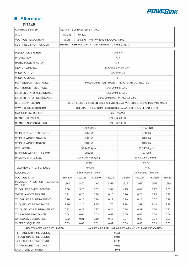
AlternatorPI734B
CONTROL SYSTEM SEPARATELY EXCITED BY P.M.G.
123XM143XM.R.V.A
VOLTAGE REGULATION ± 1% ± 0.5 % With 4% ENGINE GOVERNING
SUSTAINED SHORT CIRCUIT
INSULATION SYSTEM
PROTECTION
RATED POWER FACTOR
STATOR WINDING
WINDING PITCH
WINDING LEADS
MAIN STATOR RESISTANCE
MAIN ROTOR RESISTANCE
EXCITER STATOR RESISTANCE
EXCITER ROTOR RESISTANCE
srehto rof yrotcaf ot refer .N5780 EDV ,G5780 EDV,4-6-00016 NE SB & 2-6-00016 NE SBNOISSERPPUS .I.F.R
%0.5 < DAOL RAENIL DECNALAB GNITROTSID-NON %5.1 < DAOL ONNOITROTSID MROFEVAW
niM/veR 0522DEEPSREVO MUMIXAM
3C 8226 .LLAB DNE EVIRD GNIRAEB
3C 9136 .LLABDNE EVIRD-NON GNIRAEB
GNIRAEB 2GNIRAEB 1
WEIGHT COMP. GENERATOR
WEIGHT WOUND STATOR
WEIGHT WOUND ROTOR
WR² INERTIA
SHIPPING WEIGHTS in a crate
PACKING CRATE SIZE
TELEPHONE INTERFERENCE
COOLING AIR
772/084662/064452/044042/614452/044042/514132/004022/083RATS EGATLOV
kVA BASE RATING FOR REACTANCE VALUES 1360 1400 1400 1375 1525 1625 1655 1690
Xd DIR. AXIS SYNCHRONOUS 3.50 3.26 3.02 2.64 4.25 4.04 3.77 3.53
X'd DIR. AXIS TRANSIENT 0.21 0.20 0.18 0.16 0.26 0.25 0.23 0.22
X''d DIR. AXIS SUBTRANSIENT 0.16 0.15 0.14 0.12 0.19 0.18 0.17 0.16
Xq QUAD. AXIS REACTANCE 2.26 2.10 1.95 1.70 2.74 2.61 2.43 2.28
X''q QUAD. AXIS SUBTRANSIENT 0.32 0.29 0.27 0.24 0.38 0.37 0.34 0.32
XL LEAKAGE REACTANCE 0.04 0.04 0.03 0.03 0.05 0.05 0.04 0.04
X2 NEGATIVE SEQUENCE 0.22 0.21 0.19 0.17 0.27 0.26 0.24 0.23
X0 ZERO SEQUENCE 0.03 0.03 0.02 0.02 0.03 0.03 0.03 0.03
REACTANCES ARE SATURATED VALUES ARE PER UNIT AT RATING AND VOLTAGE INDICATED
s31.0.TSNOC EMIT TNEISNART d'Ts10.0.TSNOC EMITSNART-BUS d''Ts41.2.TSNOC EMIT DLEIF .C.O od'T
s20.0.TSNOC EMIT ERUTAMRA aT
dX/1OITAR TIUCRIC TROHS
1.67 Ohms at 22°C
17.5 Ohms at 22°C
DOUBLE LAYER LAP
0.063 Ohms PER PHASE AT 22°C
0.0016 Ohms PER PHASE AT 22°C STAR CONNECTED
6
TWO THIRDS
0.8
IP23
CLASS H
REFER TO SHORT CIRCUIT DECREMENT CURVES (page 7)
1306 kg
2760 kg
1306 kg
1077 kg1139 kg
194 x 105 x 154(cm) 194 x 105 x 154(cm)
32.7498 kgm2
gk9772 gk3382
mfc 0037 ces/³m 54.3mfc 0075 ces/³m 96.2
50 Hz
THF<2%
60 Hz
TIF<50
2710 kg
31.7489 kgm2
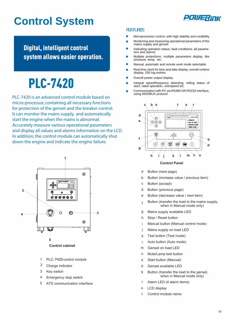
PLC-7420 is an advanced control module based on
for protection of the genset and the breaker control.It can monitor the mains supply, and automatically start the engine when the mains is abnormal. Accurately measure various operational parametersand display all values and alarms information on the LCD.In addition, the control module can automatically shutdown the engine and indicate the engine failure.
10
PLC-7420
Control System
Digital, intelligent controlsystem allows easier operation.
FEATURESMicroprocessor control, with high stability and credibilityMonitoring and measuring operational parameters of themains supply and gensetIndicating operation status, fault conditions, all parame-ters and alarmsMultiple protections; multiple parameters display, likepressure, temp. etc.Manual, automatic and remote work mode selectable
Real time clock for time and date display, overall runtimedisplay, 250 log entries
Overall power output display
Integral speed/frequency detecting, telling status ofstart, rated operation, overspeed etc.Communication with PC via RS485 OR RS232 interface,using MODBUS protocol
micro-processor, containing all necessary functions
74207420
08
Control System
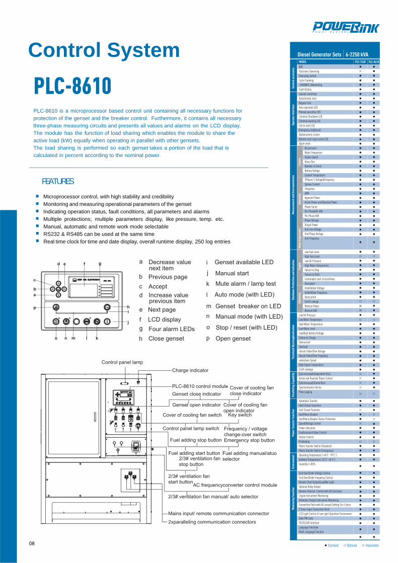
PLC-8610
FEATURES
Gene
ral a
cces
sory
PLC-8610
Oper
ator
Inte
rfac
eM
easu
rem
ent a
nd In
stru
men
tatio
nSh
utdo
wn
Prot
ectio
n an
d In
dica
tion
Thre
shol
d W
arni
ng&I
ndic
atio
nPa
ralle
ling
Capa
bilit
yPo
wer
Tran
sfer
Func
tion
Envi
ronm
ent
Mon
itorin
g Fu
nctio
n
Engi
neEn
gine
Alta
mat
orAl
tam
ator
Mai
ns E
xpre
ssio
n
AVRElectronic GoverningGlow plug controlCycle Cranking(MODBUS)NetworkingFault Historymanual start/stopAuto/remote startRegular TestAuto operation LEDManual operation LEDCommon Shutdown LEDCommon warning LEDFail to start LEDEmergency stop(local)Alphanumeric screenRemote start input active LEDAlarm reset Oil pressure Water Temperture Engine Speed Hours Run Number of Starts Battery Voltage Coolant Temperature 3PhaseL-L Voltage&Frequency 3phase Current Frequency kWh Apparent Power Active Power and Reactive Power Power Factor Per PhasekW, kWr Per Phase kVA Phase Voltage Output Power Grid Line Voltage Grid Phase Voltage Grid Frequency
Low Fuel Level High Fuel Level Low Oil Pressure High Water Temperature Failure to Stop Failure to Start Controlable start circles/times Overspeed Under&Over Voltage Under&Over Frequency Overcurrent Earth Leakage Reverse Power Reverse kWrLow Oil PressureLow Water TemperatureHigh Water TemperatureLow Water LevelLow/High Battery VoltageFailure to ChargeOvercurrentOverloadGenset Under/Over VoltageGenset Under/Over Frequencyunder/over SpeedHigh Engine TemperatureEarth LeakageSynchroscope(Independent Bus) Active and Reactive Power Control Synchroscope(Shared Bus) Synchronization Dector Peak Lopping
Automatic Transfer Hard Closed Transition Soft Closed Transtion Gen/Mains Breaker Gen/Mains Breaker Status Protection Speed/Voltage Control Power Indication Fuel&solenoid Valve Control Startor Control Preheating Mains Transfer Switch (Standard) Mains Transfer Switch (Emergency)Operating Temperature (-40℃-70℃) Ambient Temperature (-25℃-45℃) Humidity≤80%
Grid Over/Under Voltage Control Grid Over/Under Frequency Control Remote Start Output(Load/No-load) Optional Relay Output Remote Telecom Control with All Functions Engine Instrument Monitoring Altemator Output Instrument Monitoring Connection Point with All-around Setting For 6 Users 3 Users Input Connection Point LCD Light Control of Low Light Operation Environment Safe PIN CodeRS232/485 Interface Language Selection Multi-Language Function
MODEL
Diesel Generator Sets 6-2250 kVA
Standard Optional Impossible
PLC-7420
Microprocessor control, with high stability and credibilityMonitoring and measuring operational parameters of the gensetIndicating operation status, fault conditions, all parameters and alarmsMultiple protections; multiple parameters display, like pressure, temp. etc.Manual, automatic and remote work mode selectableRS232 & RS485 can be used at the same timeReal time clock for time and date display, overall runtime display, 250 log entries
PLC-8610 is a microprocessor based control unit containing all necessary functions for
The module has the function of load sharing which enables the module to share the
calculated in percent according to the nominal power.
protection of the genset and the breaker control. Furthermore, it contains all necessarythree-phase measuring circuits and presents all values and alarms on the LCD display.
active load (kW) equally when operating in parallel with other gensets.The load sharing is performed so each genset takes a portion of the load that is

Engine Alternator Generator Set Fuel System Canopy
Exhaust System Cooling System Control Panel Voltages
● Water Jacket Preheater● Oil Preheater
Optional
●Winding Temperature Measuring Instrument●Alternator Preheater● PMG ● Anti-damp and anti-corrosion treatment● Anti-condensation heater
● Tools with the machine ● Low fuel level alarm● Automatic fuel feeding system● Fuel T-valves
● Oil with the machine ● Protection board from hotness
● Front heat protection● Coolant (-30°C)
● Remote control panel● PLC-7420● PLC-8610● ATS
● 415/240V● 400/230V● 380/220V● 220/127V● 200-115V
Lubricating System
www.powerlinkworld.com
PowerLink reserves the right to make changes in model, technical sepcification, color, configuration and accessories without prior notice. Please contact the salesman before ordering.
WCS Series / Mar.2011, Edition 6220003