Embed Size (px)
Citation preview

ISSN 1061�8309, Russian Journal of Nondestructive Testing, 2011, Vol. 47, No. 12, pp. 834–841. © Pleiades Publishing, Ltd., 2011.Original Russian Text © A.A. Jezhora, A.M. Navumenka, 2011, published in Defektoskopiya, 2011, Vol. 47, No. 12, pp. 67–76.
834
INTRODUCTION
Depending on its spinning capability, flax fibers are classified into hackled fiber, flax tow, and shortfiber. Such a classification is caused by the peculiarities of the mechanical technology of its scutching andhackling. The presence of short fibers in hackled flax fiber considerably worsens the process of spinningand the quality of the obtained yarn. When the quality of flax fiber is evaluated, great attention is paid tothe homogeneity of fibers and the degree of their purification from unspinnable admixtures, which havean effect on the quality of yarn, its breakage, and the consumption of raw flax fiber per unit yarn mass. Theproblems of the nondestructive testing (NDT) of the quality of flax fiber are intimately associated with themonitoring of its physicomechanical properties. Flax fiber is characterized by the presence of all�skin cel�lulose and uniaxial anisotropy in its dielectric properties.
Studies of the anisotropy of fibers are associated with the measurement of the dielectric permittivitytensor constants εx, εy, and εz. The differences in their values are small, so the error caused by the looseattachment of electrodes to an inspected surface and the edge effect at the ends of electrodes, where a fieldis not plane–parallel, may lead not only to quantitative, but also to qualitative changes in the understand�ing of the anisotropy of an inspected fiber. In this connection, there is a need for the evaluation of anisot�ropy without replacing electrocapacitance transducers. The solution of this problem is associated with thedesign of differential electrocapacitance transducers in the form of multisection screened attachable mea�suring capacitors (MSAMCs) [1] that provide the generation of fields along and across fibers and the mea�surement of the difference between two capacitors. The choice of the differential measurement method isexplained by the fact that the field at the ends of an electrocapacitance transducer is oriented in all direc�tions and the capacity contributed by the ends is the integral characteristic of an anisotropic material. Thiscontribution can be eliminated only by the application of a differential signal, as the ratio of signals doesnot allow us to remove this error. In the case of determining the dielectric permittivity tensor constantsthemselves, it is necessary to use two identical electrocapacitance transducers with different lengths L1 andL2 of electrodes. The difference between the transducer capacitors measured for the different lengths L1
and L2 of electrodes and the orientation of their fields in the same direction of a structure characterizesthe electrode unit�length capacitance without consideration for the edge effects at the ends of electrodes.
As well as the elimination of the error caused by the edge effect, the differential measurement methodallows us to reduce the influences of the air gaps between a specimen and measuring electrodes and thestray capacitance that appears in the substrate of an MSAMC.
ELECTROMAGNETIC AND ELECTRICAL METHODS
Dielectrometry of Orthotropic Textile MaterialsA. A. Jezhora* and A. M. Navumenka**
Vitebsk State Technological University, Moskovskii pr. 72, Vitebsk, 210035 Belarus* e�mail: [email protected]
** e�mail: [email protected] May 25, 2011
Abstract—The model of an attachable electrocapacitance screened transducer was considered. Thedirect and inverse problems were solved and the inspection zones of a transducer and also its optimalconstruction parameters that provide a high sensitivity to anisotropy in the dielectric properties oforthotropic materials were determined. The effective dielectric permittivity of a flax fiber was studiedat different humidities depending on the frequency of an electromagnetic field oriented along or acrossthe fiber. A dielectrometric method for evaluating the quality of a flax fiber was developed.
Keywords: attachable electrocapacitance screen�equipped transducer model, anisotropy, sensitivity.
DOI: 10.1134/S1061830911120059

RUSSIAN JOURNAL OF NONDESTRUCTIVE TESTING Vol. 47 No. 12 2011
DIELECTROMETRY OF ORTHOTROPIC TEXTILE MATERIALS 835
MODEL OF A MULTISECTION SCREENED ATTACHABLE MEASURING CAPACITOR
The profile of an MSAMC section is illustrated in Fig. 1. Tape electrodes 1 and 2 generate a plane–parallel field, excluding the field at the ends of electrodes. The contribution of the field at the ends of elec�trodes becomes appreciable when the MSAMC width Nr (where N is the number of sections and r is thewidth of a single section) is comparable with the length L of the electrodes. Screen 4 above the inspectedmaterial assists in the monitoring of anisotropy in the dielectric properties of fine polymer materials. Itperforms two functions: first, it eliminates the cumulative effect and, second, draws a fraction of the fluxof the force lines, thus increasing the horizontal component of the electric field intensity and the sensitiv�ity of the MSAMC to anisotropy in the dielectric properties in the plane of a material.
The operational capacitance of an MSAMC is determined by two force line fluxes that close on low�potential electrode 2. The first flux closes over the surface of the electrodes in the inspection region andpartially penetrates into the region of the substrate and the second flux closes in the substrate so that thestray component of the operational capacitance depends on the dielectric properties of the inspectedspecimen and may be reduced by the proper selection of the material and geometrical dimensions for thesubstrate. The working area of inspection does not entirely cover the inspected specimen. It is determinedby the interface between the fluxes that close on screens 3 and 4 and requires the calculation of the widthand depth of the inspection zones. The equipotential lines of an electrical field in air (ε2 = ε3 = 1) werecalculated after the discrete values of the surface charge density distribution on each two sides of elec�trodes were found: σ1k(x) and σ2k(x) on the first and second electrodes, respectively, and σ3(x) and σ4(x)on the screens according to the results from [1].
The potentials of field points were calculated as follows.In the substrate (0 < z ≤ b),
V x z,( ) 1ε1ε02π������������� β21ψi x b z– d+,( ) γsβ21ψi x 2s h1 d+( ) b z– d+ +,( )[
s 1=
T
∑+i 1=
n1 … n2+ +
∑=
+ γs 1– β21λ23ψi(x,������b z– 2s h1 d+( ) d–+ )] ψi x y,( ) λ12ψi x 2b z–,( )������+i n1 … n4 1+ + +=
n1 … n2+ +
∑+
+ λ23β12β21ψi x 2 b d h1+ +( ) z–,( ) β12β21γsλ23ψi x 2b z– 2 s 1+( ) h1 d+( )+,( )
s 1=
T
∑+
+ β32β21ψi x b z– h h1 d+ + +,( ) β32β21γsψi x b z– h+ 2 s 1+( ) h1 d+( )+,( )
s 1=
T
∑+ .
i n1 … n5 1+ + +=
n1 … n6+ +
∑
Z
1 2
3
4
ε4σ3 = 0 h
ε2
d σ11(x) σ21(x) b
σ1 = 0 σ12(x) ε1
0r0
r3
r
σ22(x)X
σ3(x)
h1
σ4(x)
Fig. 1. Profile of an MSAMC section.

836
RUSSIAN JOURNAL OF NONDESTRUCTIVE TESTING Vol. 47 No. 12 2011
JEZHORA, NAVUMENKA
In the air gap ((b + d) < z ≤ (b + d + h1),
In the inspected medium (z > (b + d + h1),
where ψi(x, ϕ) is the auxiliary function.
V x z,( ) 1ε2ε02π������������� ψi x z b– d–,( ) λ21ψi x z b– d+,( ) γsλ21ψ1i x 2s 1+( )d 2s 1–( )+,([
s 1=
T
∑+ +i 1=
n1 … n2+ +
∑=
× h1 z+ ) γsψi x 2s h1 d+( ) z b– d–( )+,( ) γsψi x 2s h1 d+( ) z b– d–( )–,( ) γs 1– λ23ψi x 2sh1,(++ +
������ – z b–( ) 2s 1+( )d )+ ] 1 λ21+( )ψi x z b–,( ) γs1 λ21+( )ψi x 2s, h1 d+( )(
s 1=
T
∑+i n1 … n2 1+ + +=
n1 … n4+ +
∑+
z������+ z b)– γs λ23γ
s 1–+( ) 1 λ21+( )ψi x 2s d h1+( ) z b–( )–,( )+
+ γs 1– λ23β12ψi x 2b 2s d h1+( )+, d– z–( ) γsβ12ψi x 2s d h1+( ), z+( ) ]+[s 1=
T
∑i n1 … n4 1+ + +=
n1 … n5+ +
∑
������+ β12ψ3i x z,( ) γsλ21β32ψi x h z b– 2s 1+( ) d h1+( )+ +,( )[s 1=
T
∑s 1=
n1 … n6+ +
∑+
������+ γsβ32ψi x h b h1 2s d h1+( ) z–+ + +,( ) ] β32ψi x h d h1 b z–+ + +,( )+ .
V x z,( ) 1ε3ε02π������������� β23ψi x z b– d–,( ) β23λ21ψi x z b– d+,( ) γsλ21β23ψi x 2 s 1+( )d,([
s 1=
T
∑+ +i 1=
n1 … n2+ +
∑=
2������+ 2sh1 z b– d)– γsβ23ψi x 2s h1 d+( ), z b– d–( )+( )]+ + 1 λ21+( )β23ψi x z b–,( )�����
i n1 … n2 1+ + +=
n1 … n4+ +
∑+
+ [γsβ23 1 λ21+( )ψi x 2s h1 d+( ) z b+ +,( )]s 1=
T
∑ γsβ12β23ψi x 2s d h1+( ) z+,( )s 0=
T
∑i n1 … n4 1+ + +=
n1 … n5+ +
∑+
+ γsβ32β23λ21ψi x 2 s 1+( ) d h1+( ) h z b–+ +,( )s 0=
T
∑i n1 … n5 1+ + +=
n1 … n6+ +
∑
������+ ψi x h h1 d z– b+ + +,( ) λ32ψi x h z h1 d– b––+,( )+ ,
ψi x ϕ,( ) σ t( )2
�������� 2rm t x+ +( )2 ϕ2+ 2rm t– x+( )2 ϕ2+ 2rm t x–+( )2 ϕ2+ln
αi
βi
∫m 1=
N
∑=
× 2rm t– x–( )2 ϕ2 dt σ t( )/2
αi
βi
∫ t x–( )2 ϕ2+ln++ t x+( )2 ϕ2+ ,
RUSSIAN JOURNAL OF NONDESTRUCTIVE TESTING Vol. 47 No. 12 2011
DIELECTROMETRY OF ORTHOTROPIC TEXTILE MATERIALS 837
where N is the number of sections to the right and left from the central section, αi and βi are the boundariesof the areas of the integration of a charge that creates a field at the point x, and T is the number of reflec�tions. The transmission coefficients βij, the reflection coefficients λij, and the double reflection coefficientγ were calculated in compliance with [2] as
taking into account that ε3 = and h = h = d = in air, where h',
and d' are the thicknesses of the inspected specimen, the air gap, and the electrodes, respectively.
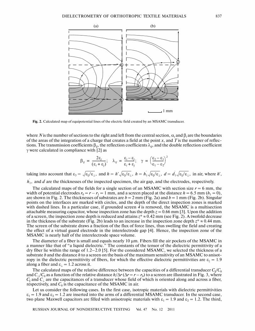
The calculated maps of the fields for a single section of an MSAMC with section size r = 6 mm, thewidth of potential electrodes r0 = r – r1 = 1 mm, and a screen placed at the distance h = 6.5 mm (h1 = 0),are shown in Fig. 2. The thicknesses of substrates are b = 2 mm (Fig. 2a) and b = 1 mm (Fig. 2b). Singularpoints on the interfaces are marked with circles, and the depth of the direct inspection zones is markedwith dashed lines. In a particular case, if grounded screen 4 is removed, the MSAMC is a multisectionattachable measuring capacitor, whose inspection zone has the depth z = 0.66 mm [3]. Upon the additionof a screen, the inspection zone depth is reduced and attains z* ≈ 0.42 mm (see Fig. 2). A twofold decreasein the thickness of the substrate (Fig. 2b) leads to an increase in the inspection zone depth z* ≈ 0.44 mm.The screen of the substrate draws a fraction of the flux of force lines, thus swelling the field and creatingthe effect of a virtual guard electrode in the interelectrode gap [4]. Hence, the inspection zone of theMSAMC is nearly half of the interelectrode space volume.
The diameter of a fiber is small and equals nearly 10 μm. Fibers fill the air pockets of the MSAMC ina manner like that of “a liquid dielectric.” The constants of the tensor of the dielectric permittivity of adry fiber lie within the range of 1.2–2.0 [5]. For the considered MSAMC, we selected the thickness of asubstrate b and the distance h to a screen on the basis of the maximum sensitivity of an MSAMC to anisot�ropy in the dielectric permittivity of fibers, for which the effective dielectric permittivities are ε|| = 1.9along a fiber and ε⊥ = 1.2 across it.
The calculated maps of the relative difference between the capacities of a differential transducer C||/C0and C⊥/C0 as a function of the relative distance h/Δr (Δr = r – r0) to a screen are illustrated in Fig. 3, whereC|| and C⊥ are the capacitances of a transducer whose field of which is oriented along and across a fiber,respectively, and C0 is the capacitance of the MSAMC in air.
Let us consider the following cases. In the first case, isotropic materials with dielectric permittivitiesε1 = 1.9 and ε2 = 1.2 are inserted into the arms of a differential MSAMC transducer. In the second case,two plane Maxwell capacitors are filled with anisotropic materials with ε1 = 1.9 and ε2 = 1.2. The third,
βi j2εj
εi εj+( )���������������; λij
εi εj–εi εj+�����������; γ
ε2 ε1–ε1 ε2–������������⎝ ⎠⎛ ⎞
2
= = =
ε ||/ε⊥, h ' ε ||/ε⊥, h1' ε ||/ε⊥, d1
' ε ||/ε⊥,
h1' ,
(a) (b)
1 mm
Fig. 2. Calculated map of equipotential lines of the electric field created by an MSAMC transducer.

838
RUSSIAN JOURNAL OF NONDESTRUCTIVE TESTING Vol. 47 No. 12 2011
JEZHORA, NAVUMENKA
fourth, and fifth cases correspond to MSAMC transducers with substrate thicknesses b of 1, 2, and 4 mm,respectively. In all the last three cases, the inspected material (fiber) has the following dielectric charac�teristics: ε|| = 1.9, ε⊥ = 1.2, and σx = σy = σz = 0.
From the plots shown in Fig. 3, it follows that:(1) The relative difference of the capacitances for a differential transducer, whose arms are two plane
Maxwell capacitors, is 70% (line 2);(2) If isotropic materials with ε1 = 1.9 and ε2 = 1.2 are inserted into the arms of a differential transducer
in the form of two MSAMCs, the relative difference of the capacitances drops monotonically with adecrease in the relative distance (curve 2);
(3) For differential transducers in the form of two MSAMCs filled with an anisotropic material, the rel�ative difference of capacities is observed to attain a maximum with a change in the direction of the field(curves 3–5);
(4) The thicker a substrate is, the lower the sensitivity of an MSAMC transducer to anisotropy in thedielectric permittivity is; and
(5) The maximum sensitivities of the transducers to anisotropy in the dielectric permittivity are shiftedrelative to each other: the thicker a substrate is, the longer the relative interelectrode distance h/Δr thatcorresponds to the maximum sensitivity of transducers to anisotropy in the dielectric permittivity is.
The presence of a maximum in the dependence of the relative difference of the capacitances (C|| – C⊥)/C0
on the relative interelectrode distance h/(r – r0) indicates that the sensitivity to anisotropy is increased upto a certain limit with a decrease in the distance from screen 4 to the plane of the MSAMC electrodes.This is caused by an increase in the horizontal field intensity component. Screen 4 then begins to act (seeFig. 4), drawing a fraction of the flux of force lines and thereby decreasing the horizontal field intensity
120
100
80
60
40
20
03.252.251.250.25 h/Δr
1
2
3
4
5
(C|| – C⊥)/C0/(h/Δr), %
Fig. 3. Relative difference of the capacitances of a differential transducer as a function of the relative interelectrode dis�tance h/Δr.

RUSSIAN JOURNAL OF NONDESTRUCTIVE TESTING Vol. 47 No. 12 2011
DIELECTROMETRY OF ORTHOTROPIC TEXTILE MATERIALS 839
component, so that the sensitivity drops. When the relative distance h/(r1–r0) ∞, the relative differ�ence of the capacitances of the MSAMC tends to the relative distance of the capacitances of multisectionMSAMCs. It does not depend on the gap h and is marked with straight lines in Fig. 3. Separately, thedependence of the relative difference of capacitances for a differential transducer, whose arms are twoplane Maxwell capacitors, is denoted with a dashed line (line 2). The optimal distance h from screen 4 tothe plane of electrodes should be considered to lie within the range from (r1 – r0) to 2(r1 – r0).
Dielectric permittivity is caused by the polarization of a substance during its displacement in an electricfield. As the dipole moment of polar water molecules in a free state (p = 6.2 × 10⁻³⁰ C m) is several ordersof magnitude higher than the dipole moment of the nonpolar molecules that predominantly constitute theskeletons of the inspected materials (textile and building materials), the effective dielectric permittivity ofa wet material is a function of humidity. This property of water molecules is enhanced during the inspec�tion of anisotropic materials. In the electric field of a material, water dipoles are oriented in the directionof its structure. If an external electric field coincides with the direction of the structure, water moleculedipoles strengthen the polarization of the substance. As the direction of an external electric field changes,water molecule dipoles tend to follow it. Owing to their high mass inertia, dipoles do not always rearrangethemselves. This leads to the strengthening of the dielectric permittivity anisotropy at low frequencies (1–10 kHz) and the weakening of this effect at high frequencies (100–500 kHz).
The effective dielectric permittivity as a function of the frequency of an electromagnetic field ν at dif�ferent flax fiber humidities W in the direction of a fiber (ε||) and perpendicular to it (ε⊥) is plotted in Fig. 4.The effective dielectric permittivity of a fiber is considered to mean the resulting permittivity of the fiberitself, the air occupying a certain fraction of space, and water.
We solved the inverse problem for an MSAMC transducer on a Teflon substrate (ε1 = 2.1) with a thick�ness of 2 mm and geometric dimensions r = 6.82 mm, r0 = 1.60 mm, r1 = 5.22 mm, h = 6.50 mm, andμ = 0.035 mm. Knowing the geometric dimensions of a transducer and the measured capacity, we deter�
4.0
3.5
3.0
2.0
2.5
1.5
1.05.04.54.03.53.02.6
log10ν
ε
ε||hackl, W = 4%
ε||cott, W = 3.68%
ε||hackl, W = 0%
ε||short, ε||
cott, W = 0%
ε⊥, W = 0% ε⊥, W = 4%
Fig. 4. Change in the effective dielectric permittivity at different humidities W of flax and cotton fibers depending on thefrequency ν of the electromagnetic field.

840
RUSSIAN JOURNAL OF NONDESTRUCTIVE TESTING Vol. 47 No. 12 2011
JEZHORA, NAVUMENKA
mined the dielectric permittivities ε|| and ε⊥. The effective dielectric permittivity ε|| was found after the cal�culation of ε⊥, taking into account the measured capacity C||, as
The approximation reliability R2 = 0.9999.
From the plots shown in Fig. 4, it can be seen that the effective dielectric permittivities ε⊥ in the direc�tion perpendicular to a fiber almost do not depend on the frequency of the electromagnetic field withinthe frequency range of 0.5–100 kHz and remain constant: for dry hackled and cottonized flax fibers with
fiber lengths of more than 200 and of 30–70 mm, respectively, = = 1.20 ± 0.03. A slight scatteris observed for the effective dielectric permittivity in the direction of a fiber (Fig. 4). The decrease in the
length of the fiber reduces the effective dielectric permittivity ε||: = 1.97 ± 0.06 for dry hackled flax
fibers and = 1.84 ± 0.05 for cottonized flax fibers. This dependence allows us to evaluate the homo�geneity of flax fibers on the basis of the dielectric permittivities ε|| and ε⊥. As ε|| increases, the quality offibers becomes higher.
For dry fibers, the scatter of the dielectric permittivity is almost not observed. As the humidity of inspectedfibers increases, the anisotropy in the dielectric permittivity is increased. The increase in the dielectric permit�tivity anisotropy at a frequency of 0.5 kHz is much higher than that at a frequency of 100 kHz. For hackled flax
fibers at a humidity W = 4.0%, the relative anisotropy of the dielectric permittivity ( – ε⊥)0.5/( –
ε⊥)100 = 4.8 and, for dry flax fibers at a humidity W = 0% ( – ε⊥)0.5/( – ε⊥)100 = 1.1. The relative
anisotropy of the dielectric permittivity of cotton fibers at a humidity W = 3.7% is ( – ε⊥)0.5/( – ε⊥)100 =
2.3 and for dry cotton fibers at a humidity W = 0%, ( – ε⊥)0.5/( – ε⊥)100 = 1.1. The relative anisotropyof the dielectric permittivity (ε|| – ε⊥)0.5/(ε|| – ε⊥)100 is a parameter for the estimation of the humidity of flaxfibers.
CONCLUSIONS
A dry fiber has no scatter of dielectric permittivity in the direction perpendicular to the fiber. A slightscatter is observed for the constants of the tensor of the dielectric permittivity in the direction of the fiber.A considerable growth in the anisotropy of the dielectric permittivity of fibers with an increase in theirhumidity is observed within the region of low frequencies. The dependence of the relative anisotropy ofthe dielectric permittivity on the humidity provides the basis for the humidity gauging of flax and cottonfibers and fiber blends. The quality of fibers may be evaluated on the basis of the dielectric permittivity ten�sor constants ε|| and ε⊥. The higher the quality of a fiber is, the higher the constants of the tensor of thedielectric permittivity in the direction of the fiber are.
REFERENCES
1. Jezhora, A.A., Modeling of Attachable Measuring Capacitors in the Presence of a Grounded Plane, Metrolog.Pribor., 201 0, no. 2, pp. 38–42
ε⊥ f C⊥ r r0 h d ε1, , , , ,( ) 0.1668C⊥
40.6838C⊥
31.1652C⊥
34.6775C⊥ 0.3481;–+ + +–= =
ε || f C || r r0 r1 h d b ε1, , , , , , ,( ) 0.048372C⊥
4 0.198302C⊥
3 0.337908C⊥
2 1.356475C⊥ 0.535049 )+–+–(= =
× C ||4 0.2533692C⊥
4 1.0386922C⊥
3 1.7699388C⊥
2 7.105122C⊥ 2.9781639)C ||3+–+–(–
+ 0.7654452C⊥
4 3.1379582C⊥
3– 5.3471028C⊥
2 21.4650475C⊥ 11.0427309+–+( )C || 2
– 0.1089204–( C⊥
4 0.4465214C⊥
3 0.7608756C⊥
2 3.0544075C⊥ 1.3047907+ + )C || 0.0128436C⊥
4––+
+ 0.0526526C⊥
3 0.0897204C⊥
2 0.3601675C⊥ 0.2183037.–+–
ε⊥hack ε⊥
short
ε⊥hack
ε ||short
ε ||hack ε ||
hack
ε ||hack ε ||
hack
ε ||tcot ε ||
tcot
ε ||tcot ε ||
tcot
RUSSIAN JOURNAL OF NONDESTRUCTIVE TESTING Vol. 47 No. 12 2011
DIELECTROMETRY OF ORTHOTROPIC TEXTILE MATERIALS 841
2. Jezhora, A.A., Elektroemkostnye preobrazovateli i metody ikh rascheta (Electrocapacitance Transducers andMethods of Their Calculation), Minsk: Belorus. Nauka, 2007.
3. Mamishev, A.V., Lesieutre, B.C., and Zahn, M., Optimization of Multi�Wavelength Interdigital DielectrometryInstrumentation and Algorithms, IEEE Trans. Dielectr. Electr. Insul., 1998, vol. 5, no. 3, pp. 408–420.
4. Jezhora, A.A. and Rubanik, V.V., Effect of the Screen of a Substrate on the Capacity of a Transducer, Trudy IIIMezhdunar. nauch.�tekhn. konf. “Sovremennye metody i pribory kontrolya kachestva i diagnostiki sostoyaniyaob”ektov” (Proc. of III Int. Sci.�Techn. Conf. “Modern Methods and Equipment for the Quality Inspection andDiagnostics of the State of Objects”), Mogilev, 2009, pp. 110–112.
5. Radovitskii, V.P. and Strel’tsov, B.N., Elektrodinamika tekstil’nykh volokon (Electrodynamics of Textile Fibers),Moscow: Legkaya Ind., 1967.