Embed Size (px)
Citation preview

DIE STEELS ANDIMPROVED PRODUCTIVITYIN DIE CASTING
Great Tooling Starts Here!
T O O L S T E E L A P P L I C A T I O N
2
Die Casting
ContentsIntroduction _____________________________ 3Demands on the die cast product ____________ 3Aspects of design _________________________ 4Die making______________________________ 4Dimensional stability ______________________ 6Die Performance _________________________ 7Demands on die steels for die casting ________ 9Die economy ____________________________ 13Product program _________________________ 14Steel and hardness recommendations ________ 15
This information is based on our present state of knowledge and isintended to provide general notes on our products and their uses. Itshould not therefore be construed as a warranty of specific propertiesof the products described or a warranty for fitness for a particularpurpose.

3
Die Casting
IntroductionPressure die casting offers an economical way ofproducing large quantities of complex, high-tolerance parts in aluminum, magnesium, zinc andcopper alloys.
The continued growth of the die castingprocess depends, to a large extent, on the greateruse of die castings in the automotive industry,where weight reduction is increasingly important.
Long production runs have focused attentionon the importance of obtaining improved die life.During the last years Uddeholm has occupied aleading role in developing die materials to meetthis demand and that of higher die steel specifica-tions. This has resulted in the grades ORVARSUPREME, QRO 90 SUPREME and now DIEVAR.
Die casters are now experiencing real savingsin production and tooling costs by using thesepremium die steels with closely specified heattreatment procedures. Further improvements havebeen realized by paying close attention to goodproduct and die design and improved die castingpractices.
Demands on theDie Cast ProductIncreasing demands on die cast products willensure continued development of die casting alloyswith higher strength and ductility, improvedmachinability, weldability and corrosion resistance.
The trends in product design are goingtowards:• larger components• thinner wall thicknesses• more complicated shapes• closer tolerances
These factors favor the use of high pressuredie casting over other casting methods like lowpressure and gravity die casting.
4
Die Casting
GUIDELINES FOR SIZING
The following are some guidelines for sizing a diefor aluminum to meet strength requirements:1. Distance from cavity to outer surface
>2 in (50 mm)2. Ratio of cavity depth to total thickness <1:33. Distance from cavity to cooling channel
>1 in (25 mm)Distance from cavity to cooling channel atcorner >2 in (50 mm)
4. Fillet radii Zinc Aluminum Brass>0.02 in >0.04 in >0.06 in(0.5 mm) (1 mm) (1.5 mm)
5. Distance from gate to cavity wall >2 in (50 mm).
Aspectsof Die DesignThe design of a die casting die is primarily deter-mined by the shape of the finished component.But there are a number of aspects involved in thedesign and sizing of a die which can have an in-fluence and important bearing on die life.
CAVITY
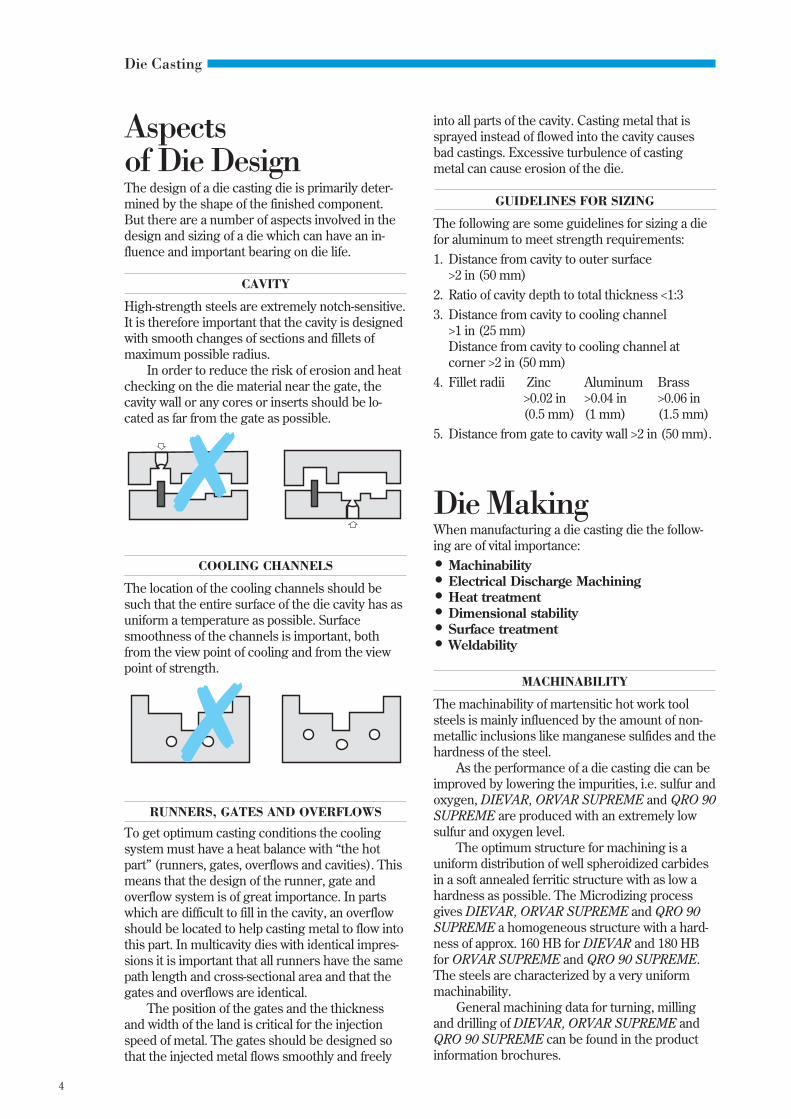
High-strength steels are extremely notch-sensitive.It is therefore important that the cavity is designedwith smooth changes of sections and fillets ofmaximum possible radius.
In order to reduce the risk of erosion and heatchecking on the die material near the gate, thecavity wall or any cores or inserts should be lo-cated as far from the gate as possible.
COOLING CHANNELS
The location of the cooling channels should besuch that the entire surface of the die cavity has asuniform a temperature as possible. Surfacesmoothness of the channels is important, bothfrom the view point of cooling and from the viewpoint of strength.
RUNNERS, GATES AND OVERFLOWS
To get optimum casting conditions the coolingsystem must have a heat balance with “the hotpart” (runners, gates, overflows and cavities). Thismeans that the design of the runner, gate andoverflow system is of great importance. In partswhich are difficult to fill in the cavity, an overflowshould be located to help casting metal to flow intothis part. In multicavity dies with identical impres-sions it is important that all runners have the samepath length and cross-sectional area and that thegates and overflows are identical.
The position of the gates and the thicknessand width of the land is critical for the injectionspeed of metal. The gates should be designed sothat the injected metal flows smoothly and freely
MACHINABILITY
The machinability of martensitic hot work toolsteels is mainly influenced by the amount of non-metallic inclusions like manganese sulfides and thehardness of the steel.
As the performance of a die casting die can beimproved by lowering the impurities, i.e. sulfur andoxygen, DIEVAR, ORVAR SUPREME and QRO 90SUPREME are produced with an extremely lowsulfur and oxygen level.
The optimum structure for machining is auniform distribution of well spheroidized carbidesin a soft annealed ferritic structure with as low ahardness as possible. The Microdizing processgives DIEVAR, ORVAR SUPREME and QRO 90SUPREME a homogeneous structure with a hard-ness of approx. 160 HB for DIEVAR and 180 HBfor ORVAR SUPREME and QRO 90 SUPREME.The steels are characterized by a very uniformmachinability.
General machining data for turning, millingand drilling of DIEVAR, ORVAR SUPREME andQRO 90 SUPREME can be found in the productinformation brochures.
Die MakingWhen manufacturing a die casting die the follow-ing are of vital importance:• Machinability• Electrical Discharge Machining• Heat treatment• Dimensional stability• Surface treatment• Weldability
✗
✗
into all parts of the cavity. Casting metal that issprayed instead of flowed into the cavity causesbad castings. Excessive turbulence of castingmetal can cause erosion of the die.

5
Die Casting
The properties of the steel are controlled bythe hardening temperature and time, the coolingrate and the tempering temperature.
A high austenitizing temperature for a die hasa positive influence on the hot yield strength andthe resistance to softening, which reduce the heatchecking tendency. In ORVAR SUPREME andQRO 90 SUPREME these properties can be en-hanced by austenitizing at 1920°F (1050°C) in-stead of the normal 1885°F (1030°C). For DIEVAR1875°F (1025°C) instead of 1830°F (1000°C).
On the other hand, a high austenitizing tem-perature gives an increased risk of grain growth,which can cause a reduction in toughness andductility. Hence the higher austenitizing tempera-ture should only be used for small dies, cores andcore pins.
Similarly, a higher hardness has a positiveeffect on heat checking, although a hardness ex-ceeding 50 HRC is not recommended for alu-minum die casting and similarly not exceeding46 HRC for brass. The risk of cracking and totalfailure increases with higher hardness.
However, by developing the higher toughnessin DIEVAR and ORVAR SUPREME, the risk offailure is considerably reduced.
The quenching rate during hardening has agreat significance for DIEVAR, ORVAR SUPREMEand QRO 90 SUPREME and for all other steels ofsimilar type.
A low quenching rate gives the best possibledimensional stability, but the risk for undesirablechanges in the microstructure of the steel in-creases.
A too low cooling rate during hardening canreduce the fracture toughness of the steel.
A high quenching rate, for example, whenusing a vacuum furnace with 5 bar pressure orhigher, gives the best possible structure and con-sequently the best die-life.
The right balance must be found between thelower rectification costs resulting from a lowquenching rate and the better die-life achieved byusing a high cooling rate. In most cases a highquenching rate is to be preferred where the totaleconomy of the die is the major consideration.
Decarburization and heavy carburization maycause premature heat checking and shall beavoided at all times.
The die should be tempered after cooling to120–160°F (50–70°C). A second tempering opera-tion is essential to obtain a satisfactory structure.The tempering temperature should be selected toobtain the desired hardness of the die. A thirdtemper is recommended for added safety.
ELECTRICAL DISCHARGE MACHINING
The use of Electrical Discharge Machining (EDM)in the production of die casting dies has beenfirmly established in recent years.
Development of the process has producedsignificant refinements in operating technique, pro-ductivity and accuracy, while increasing the ver-satility of the process. EDM continues to grow,therefore, as a major production tool in most diemaking companies, machining with equal easehardened or annealed steels.
The basic principles of EDM (spark erosion)are electrical discharges between a graphite orcopper anode and the steel, the cathode, in adielectric medium. During the process the surfaceof the steel is subjected to very high temperatures,causing the steel to melt or vaporize. A melted andbrittle resolidified layer is caused at the surfaceand beneath that a rehardened and temperedlayer.
The influence of the EDM operation on thesurface properties of the die steel can in unfavor-able circumstances destroy the working perfor-mance of the die. For this reason the followingsteps are recommended, as a precautionary mea-sure:
EDM of hardened and tempered material
A Conventional machiningB Hardening and temperingC Initial EDM, avoiding “arcing” and excessive
stock removal rates. Finish with “finesparking”,i.e. low current, high frequency
D (i) Grind or polish EDM surface(ii) Temper the tool at 30–50°F (15–25°C)
lower than the highest previous tempering temperature.
EDM of annealed material
A Conventional machiningB Initial EDM, as C aboveC Grind or polish EDM surface. This reduces
the risk of crack formation during heating andquenching. Slow preheating, in stages, to thehardening temperature is recommended.
HEAT TREATMENT
Hot work tool steels are normally delivered in thesoft annealed condition. After machining, the diemust be heat treated in order to give optimum hotyield strength, temper resistance, toughness andductility.
More information about electrical dischargemachining can be found in the brochure “EDM ofTool Steels”.

6
Die Casting
cant distortion. Step quenching is recommendedfor larger, more complex dies.
Transformation stressesThis type of stress arises when the microstructureof the steel is transformed. This is because thethree microstructures in question—ferrite, auste-nite and martensite—have different densities, i.e.volumes.
The greatest effect is caused by transforma-tion from austenite to martensite. This causes avolume increase.
Excessively rapid and uneven quenching canalso cause local martensite formation, causingvolume increases locally in a die giving rise tostresses in some sections. These stresses can leadto distortion and, in some cases, cracks.
More information about dimensional changeswhen hardening and tempering of DIEVAR,ORVAR SUPREME and QRO 90 SUPREME canbe found in the product information brochures.
SURFACE TREATMENT
Surface treatments like gas nitriding, salt bath orion nitriding can have a beneficial effect on certainparts of a die casting die, such as shot sleeves,nozzles, runners, spreaders, gates, ejector pins andcore pins. Different steels possess different nitrid-ing properties, depending on chemical composi-tion.
Other surface treatments, including the Solve-nite, Metallife and Melonite processes have alsoproved beneficial in die casting applications.
WELDABILITY
In many cases, it is important that a die casting diecan be repaired by welding. The repair-welding oftool steel always entails a risk of cracking, but if
Aluminum part for the automotive industry.
Dimensional stabilityDISTORTION DURING
THE HARDENING AND TEMPERINGOF DIE CASTING DIES
When a die casting die is hardened and tempered,some warpage or distortion normally occurs. Thisdistortion is usually greater when using higheraustenitizing temperatures.
This is well known, and it is normal practice toleave some machining allowance on the die priorto hardening. This makes it possible to adjust thedie to the correct dimensions after hardening andtempering by grinding, EDM’ing etc.
Distortion takes place because of stresses inthe material. These stresses can be divided into:• machining stresses• thermal stresses• transformation stresses
Machining stressesThis type of stress is generated during machiningoperations such as turning, milling and grinding.
If stresses have built up in a part, they will bereleased during heating. Heating reduces strength,releasing stresses through local distortion. Thiscan lead to overall distortion.
In order to reduce distortion while heatingduring the hardening process, a stress relievingoperation can be carried out. It is recommendedthat the material be stress-relieved after roughmachining. Any distortion can then be adjustedduring fine machining, prior to the hardeningoperation.
Thermal stressesThese stresses are created when the die is heated.They increase if heating takes place rapidly orunevenly. The volume of the die is increased byheating. Uneven heating can result in local vari-ations in volume growth, leading to stresses anddistortion.
Preheating in stages is always recommendedin order to equalize the temperature in the com-ponent.
An attempt should always be made to heatslowly enough so that the temperature remainsvirtually equal throughout the die.
What has been said regarding heating alsoapplies to quenching. Very powerful stresses ariseduring quenching. As a general rule, the coolingrates should be as fast as possible, relative to theacceptable distortion level.
It is important that the quenching medium isapplied as uniformly as possible. This is especiallyvalid when forced air or protective gas atmosphere(as in vacuum furnaces) is used. Otherwise tem-perature differences in the tool can lead to signifi-

7
Die Casting
Die PerformanceThe life of a die casting die varies considerablydepending on the size and design of the casting,the type of casting alloy, and the care and main-tenance of the die.
The life of a die can be prolonged by suitabletreatment before and during casting by:• suitable preheating• correct cooling• surface treatment• stress tempering
care is taken and heating instructions are followed,good results can be obtained.
Preparation before weldingParts to be welded must be adequately cham-fered and free from dirt and grease to ensure satis-factory penetration and fusion.
Welding of soft-annealed material
1 Preheat to min. 620°F (325°C).2 Start welding at this temperature. Never let the
temperature of the tool go below 620°F (325°C).Max. interpass temperature 885°F (475°C). Thebest way to keep a constant temperature of thetool during welding, is to use an insulated box withthermostatically controlled electrical elementsinside the walls.
3 After welding cool very slowly 20–40°F/h (10–20°C/h) for the first two hours and then freelyin air.
4 Soft anneal immediately after welding.
Welding of hardened and tempered material
1 Preheat to min. 620°F (325°C).2 Start welding at this temperature. Never let the
temperature of the tool go below 620°F (325°C).Max. interpass temperature 885°F (475°C). Thebest way to keep a constant temperature of thetool during welding, is to use an insulated boxwith thermostatically controlled electrical elementsinside the walls.
3 After welding cool very slowly 20–40°F/h (10–20°C/h) for the first two hours and then freelyin air.
4 Stress temper 50°F (25°C) below the highestprevious tempering temperature for two (2) hours.
ConsumablesQRO 90 WELD (SMAW) or QRO 90 TIG-WELD.More information about welding and consumablescan be found in the brochure “Welding of ToolSteel”.
ORVAR SUPREME
QRO 90 SUPREME
200 400 600 800 1000 °F
100 200 300 400 500 °C Testing temperature
DIEVAR
Impact strength
SUITABLE PREHEATING
The initial contact between a cold die casting dieand the hot casting metal causes a severe shock tothe die material. Heat checking can start at thevery first shot and quickly lead to total failure.Further, it is important to note that the impactstrength, i.e. the materials ability to withstand ther-mal and mechanical shock, is increased signifi-cantly during the first shots by proper preheatingof the tool.
It is essential, therefore that the temperaturedifference between the die surface and the moltenmetal is not too great. For this reason, preheating isalways recommended.
The most suitable preheating temperature isdependent on the type of casting alloy, but nor-mally lies between 300 and 660°F (150 and 350°C).
100 200 300 400 500 600°C Testing temperature
200 400 600 800 1000 1200°F
Preheatingrange
DIEVARQRO 90 SUPREME
Hot yield strength
ORVAR SUPREME
Preheatingrange
8
Die Casting
The curves show the range within which thematerial can be preheated. It is important not topreheat to an excessively high temperature, sincethe die may become too hot during die casting,causing a tempering back of the die material.Observe that thin ribs get hot very quickly.
The following preheating temperatures arerecommended:
Material Preheating temperature
Tin, Lead alloys 210–300°F (100–150°C)Zinc alloys 300–390°F (150–200°C)Magnesium,Aluminum alloys 355–570°F (180–300°C)Copper alloys 570–660°F (300–350°C)
It is important that heating is gradual andeven. Thermostatically controlled heating systemsare recommended.
When preheating, coolant should be graduallyapplied in order to obtain a state of equilibrium.Shock cooling should be avoided.
Dies containing inserts must be heated at aslow rate so the inserts and holders can graduallyexpand together.
CORRECT COOLING
The temperature of the die is controlled via coolingchannels and by the lubricant on the die surface.
In order to reduce the risk of heat checking,the cooling water can be preheated to approxi-mately 120°F (50°C). Thermostatically controlledcooling systems are also common. Cooling watercolder than 70°F (20°C) is not recommended.During breaks longer than a few minutes, the flowof coolant should be adjusted so that the tool doesnot cool down too much.
SURFACE TREATMENT
To avoid metal-to-die contact it is important thatthe lubricant (parting compound) adheres well tothe die surface. For example, a new or recentlyrepaired die should not have a glossy metalsurface. It is therefore a good idea to coat the diesurface with a thin oxide film to provide goodadhesion for the lubricant in the running-in period.
The surface of the die can be oxidized byheating to approx. 930°F (500°C) for one hourfollowed by cooling in air. Heating in a steamatmosphere— 930°F (500°C)—for 30 minutes alsoproduces a good oxide film, with suitable thick-ness.
To remove built-up deposits of die lubricantsafter a period of use, shot peening of the cavitysurface is recommended. This treatment alsocloses some of the heat checking cracks.It induces compressive stresses in the surfacelayer, which compensate for some of the tensilestresses which cause heat checking. Parts whichare subjected to abrasion and friction, such asejector pins and shot sleeves, may be nitrided ornitrocarburized for longer life.
STRESS TEMPERING
During die casting, the surface of the tool is sub-jected to thermal strains derived from the vari-ations in temperature; this repeated straining mayresult in residual stresses being generated in thesurface regions of the die. In most cases, such re-sidual stresses will be tensile in nature and there-by assist initiation of heat checking cracks. Stresstempering the die will reduce the level of residualtensile stress and thereby enhance die life. Werecommend, therefore, that stress tempering beperformed after the running-in period and thenafter 1000–2000 and 5000–10,000 shots. The pro-cedure is then repeated for each additional 10,000–20,000 shots, so long as the die exhibits only minoramounts of heat checking. However, there is littlepoint in stress tempering a heat checked diebecause the formation of surface cracks in itselfreduces the level of residual stress.
Stress tempering is best carried out at a tem-perature about 50°F (25°C) below the highesttempering temperature which has previously beenused during heat treatment of the die. Normally,two hours holding time at temperature should besufficient.
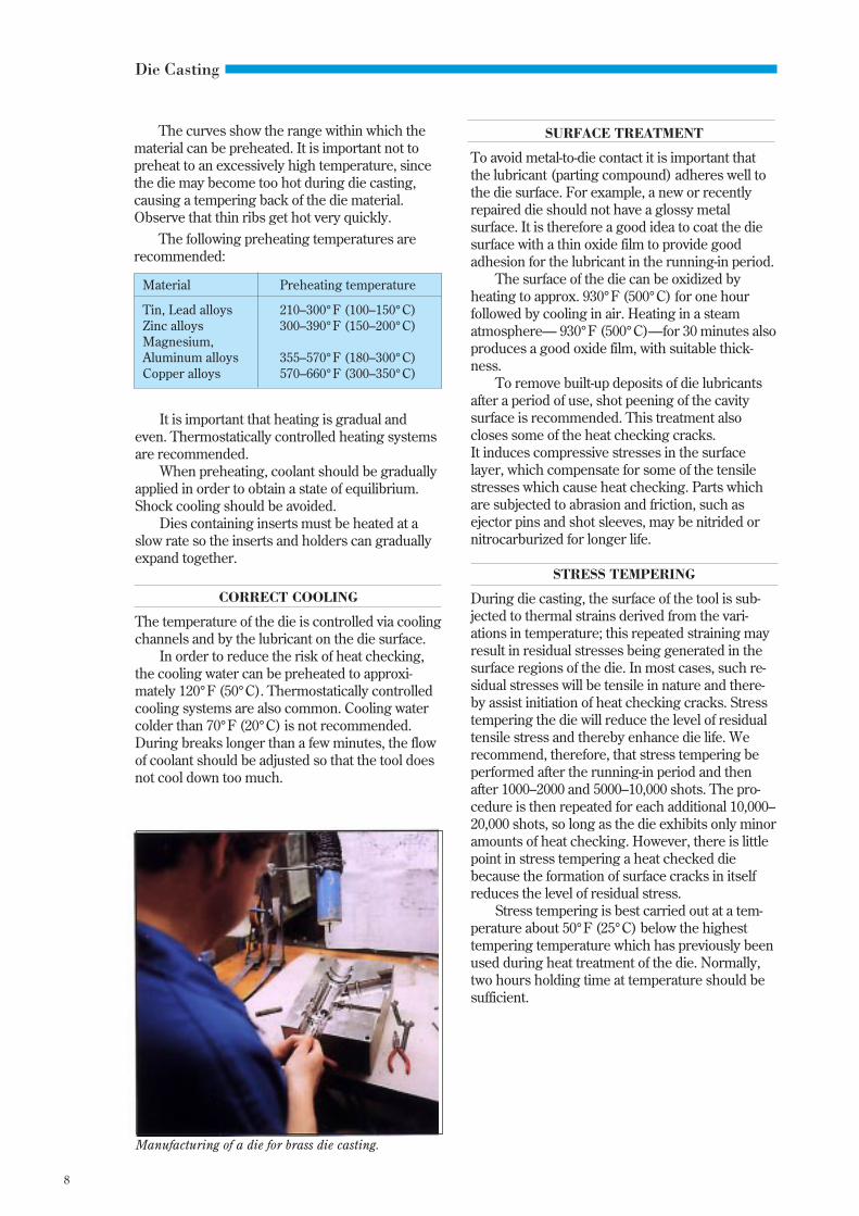
Manufacturing of a die for brass die casting.

9
Die Casting
Demands onDie Steels for DieCastingDie casting dies are exposed to severe thermaland mechanical cyclic loading, which puts highdemands on the die material. There are thus anumber of phenomena which restrict die life.The most important are:• thermal fatigue (heat checking)• corrosion/erosion• cracking (total failure)• indentation
The number of shots achievable in a die cast-ing die is strongly influenced by the working tem-perature, i.e. the casting alloy. The die life for aspecific alloy can also vary considerably due to thedesign of the cast product, the surface finish, theproduction rate, the process control, the design ofthe die, the die material, and its heat treatment andthe acceptance level of size and surface finishvariations.
Casting Casting Factors which Normal life,alloy temperature limit die life number of shots
°C °F Die Core
Zinc ~430 ~800 Erosion 0.5–2 0.5–2million million
Mag- ~650 ~1200 Heat checking 100,000 50,000nesium Cracking to to
Erosion 400,000 200,000Indentation
Alumi- ~700 ~1300 Heat checking 60,000 40,000num Cracking to to
Erosion 200,000 150,000Indentation
Copper/ ~970 ~1780 Heat checking 5,000 1,000Brass Indentation to to
Erosion 50,000 5,000Cracking
THERMAL FATIGUE
Thermal fatigue is a gradual cracking due to ther-mal stresses from many temperature cycles and isa microscale phenomenon taking place only in athin surface layer.
In use die casting dies are subjected to alter-nate heating and cooling. This gives rise to severestrains in the surface layer of the die, graduallyleading to thermal fatigue cracks. Typical thermalfatigue damage is a pattern of surface cracksknown as “heat checking”, well-illustrated in thefollowing photograph.
• Die temperature cyclePreheating temperatureSurface temperature of the dieHolding time at peak temperatureCooling rate
• Basic die material propertiesThermal expansion coefficientThermal conductivityHot yield strengthTemper resistanceCreep strengthDuctility
• Stress raisersFillets, holes and cornersSurface roughness
During the last 15 years much attention hasbeen paid to understanding the thermal fatigueprocess and to relate the resistance to heat check-ing to basic material properties. For this purposeUddeholm has built a special device for simulationof the thermal fatigue damage. The aim of theseefforts is to improve and develop the die materialand has resulted in the premium steel gradesDIEVAR, ORVAR SUPREME and QRO 90SUPREME.
Factors which influence thermal fatigueThermal fatigue cracks are caused by a combina-tion of thermal cyclic stress, tensile stress andplastic strain. If any one of these factors are notpresent, a thermal fatigue crack will neither initi-ate nor propagate. The plastic strain starts thecrack and the tensile stress promotes the crackgrowth.
The following factors influence the thermalfatigue:
10
Die Casting
DIE TEMPERATURE CYCLE
Preheating temperatureIt is essential that the temperature differencebetween the die surface and the molten metal isnot too great. For this reason preheating is alwaysrecommended.
The preheating temperature should be mini-mum 355°F (180°C) for Aluminum at whichtemperature the fracture toughness is almost twiceas high as at room temperature.
Surface temperature of the dieThe temperature of the surface layer of the die isvery important for the occurrence of thermal fa-tigue. Up to 1110°F (600°C) the thermal expansionand the stresses are moderate for a normal hotwork steel but at higher temperatures the risk ofheat checking becomes significant. The surfacetemperature of the die is mainly determined by thepreheating temperature, the casting temperatureof the metal, the design of the cast product, the dieshape and size and the thermal properties of thedie material.
Holding time at peak temperatureLonger holding time implies an increased risk ofovertempering and creep of the die material. Thismeans a reduction of the mechanical strength andaccordingly a lower resistance to mechanical and/or thermal loadings.
Cooling rateThe rate at which the surface layer cools is of con-siderable importance. More rapid cooling givesrise to greater stresses and leads to cracks at anearlier stage. The choice of coolant is normally acompromise between desired die life and produc-tion rate but most die casters have switched fromoil-based lubricants to water-based ones for envi-ronmental reasons.
BASIC DIE MATERIAL PROPERTIES
Thermal expansion coefficientThe thermal expansion coefficient ought to be lowto get low thermal stresses.
Thermal conductivityA high thermal conductivity reduces the thermalgradients and thereby the thermal stresses. It is,however, very difficult to predict or to investigateexperimentally to what extent the thermal con-ductivity influences this matter.
Hot yield strengthA high hot yield strength lowers the plastic strainand is beneficial in resisting heat checking.
Temper resistanceIf a die material with initially high hot yieldstrength becomes softer during use due to hightemperature exposure it means that the heatchecking damage accelerates. It is therefore im-portant that the die material has a good resistanceto softening at high temperature exposure.
Creep strengthThe softening associated with temper resistance isclearly accelerated by mechanical load. The diematerial is exposed both to high temperature andmechanical load. It is thus obvious that a good diematerial will possess resistance to the joint actionof high temperature and mechanical load asquantified by a high creep strength. In fact, it hasbeen proven by experiment that heat checkingcracks also can be produced by constant tempera-ture and cyclic mechanical load.
DuctilityThe ductility of the die material quantifies theability to resist plastic strain without cracking. Atthe initiation stage of the thermal fatigue damagethe ductility governs the number of cycles beforevisible cracks appear for a given hot yield strengthand temperature cycle. At the crack growth stagethe ductility has a declining influence.
The ductility of the material is greatly influ-enced by slag inclusions and segregations, i.e. thepurity and the homogeneity of the steel. The steelsfrom Uddeholm for die casting dies are thereforeprocessed in a special way. The ductility of thesteel has been considerably improved by means ofa special melting and refining technique, a con-trolled forging process and a special microstruc-ture treatment. This improvement is especiallypronounced in the center of thick blocks.
STRESS RAISERS
Fillets, holes and cornersGeometrical stress concentration and increasedthermal gradients increase the stresses and strainsat fillets, holes and corners. This means that heatchecking cracks start earlier in these areas than onplane surfaces. The joint action of heat checkingcracks and fillets increases the risk of total failureof the die.
Surface roughnessSurface defects such as grinding scratches affectthe starting of cracks for the same reasons as fil-lets, holes and corners. Within the recommended

11
Die Casting
grinding range of 220–600 grit, surface roughnessshould not be a cause of heat checking. One advan-tage with a not too highly polished surface, forexample sand blasted or oxidized, is that the part-ing lubricant adheres better and is distributedmore evenly on the surface. Further, less solderingtakes place and it gives better release of castings.This is especially important during the running-inof a new die.
CORROSION/EROSION
Corrosion by molten casting metalDuring die casting, the molten metal is injectedinto the die. In cases where the cavity surface lacksa protective layer, the cast metal will diffuse intothe die surface. At the same time, alloying ele-ments within the die (especially iron), will diffusefrom the die surface into the cast metal.These processes can create both dissolution of thesteel and intermetallic compounds between thecast metal and the die surface. In cases wheresevere formation of intermetallic compoundsoccurs, the cast metal will solder to the die surface.
Uddeholm has investigated the corrosiontendency in different molten die casting metals.
Factors which influence corrosionA number of factors influence die corrosion:• Temperature of the casting metal• Composition of the casting metal• Design of the die• Surface treatment
BrassAlZnNotrecomm.
Notrecomm.
Notrecomm.
Degree of corrosion
800 1000 1200 1400 1600 1800 °F
400 500 600 700 800 900 1000 °C Temperature
Soldering damage on a core pin.
Temperature of the casting metalThe die casting alloys have critical temperaturesabove which corrosion attacks increase. Zinc startsto react with steel at about 900°F (480°C) and alu-minum at about 1330°F (720°C). Copper alloys donot seem to have any really critical temperature,but corrosion increases slowly with temperature.
Composition of the casting metalPure metals attack tool material at a much greaterrate than commercial alloys. This is valid both forzinc (Zn) and aluminum (Al). The corrosion of thedie steel also increases when the aluminum meltcontains a low iron content.
Design of the dieDie design is also of importance for corrosion. Ifmolten metal is injected at too high a velocity, thelubricant on the surface of the cavity can be“washed” away. Too high a velocity is usuallycaused by incorrect gating design.
Surface treatmentThe surface treatment of the die steel is of greatimportance. If metallic contact between the diesteel and the molten metal can be avoided, the riskof corrosion is much less. An oxide film on the sur-face provides good protection. Nitrided or nitrocar-burized surfaces as well as other coating methodsalso give a certain protection.
ORVARSUPREME48 HRCZinc930°F (500°C)
123123
Brass1740°F (950°C)
Oxidized surfaceNon-oxidized surface
Aluminum1355°F (735°C)
Material loss
12
Die Casting
Erosion by molten casting metalErosion is a form of hot mechanical wear on thedie surface, resulting mainly from the motion ofthe melt.
Erosion depends upon the velocity of the meltas it is injected into the die as well as its tempera-ture and composition. Melt speeds in excess of180 feet/s (55 m/s) substantially increase erosiondamage.
A high temperature also affects the situation,as the surface of the die is more easily temperedback. Hard particles such as inclusions and/orprecipitated hard silicon particles, in hypereuteticaluminum melts containing more than 12.7%silicon, further increase the risk of erosion dam-age.
Most commonly a combination of corrosionand erosion damages occur on the die surface. Thetype of damage that is predominant dependslargely on the velocity of the molten metal into thedie. At high velocities, it is normally the erosiondamage which is predominant.
A good tempering back resistance and a highhot yield strength of the die material are important.
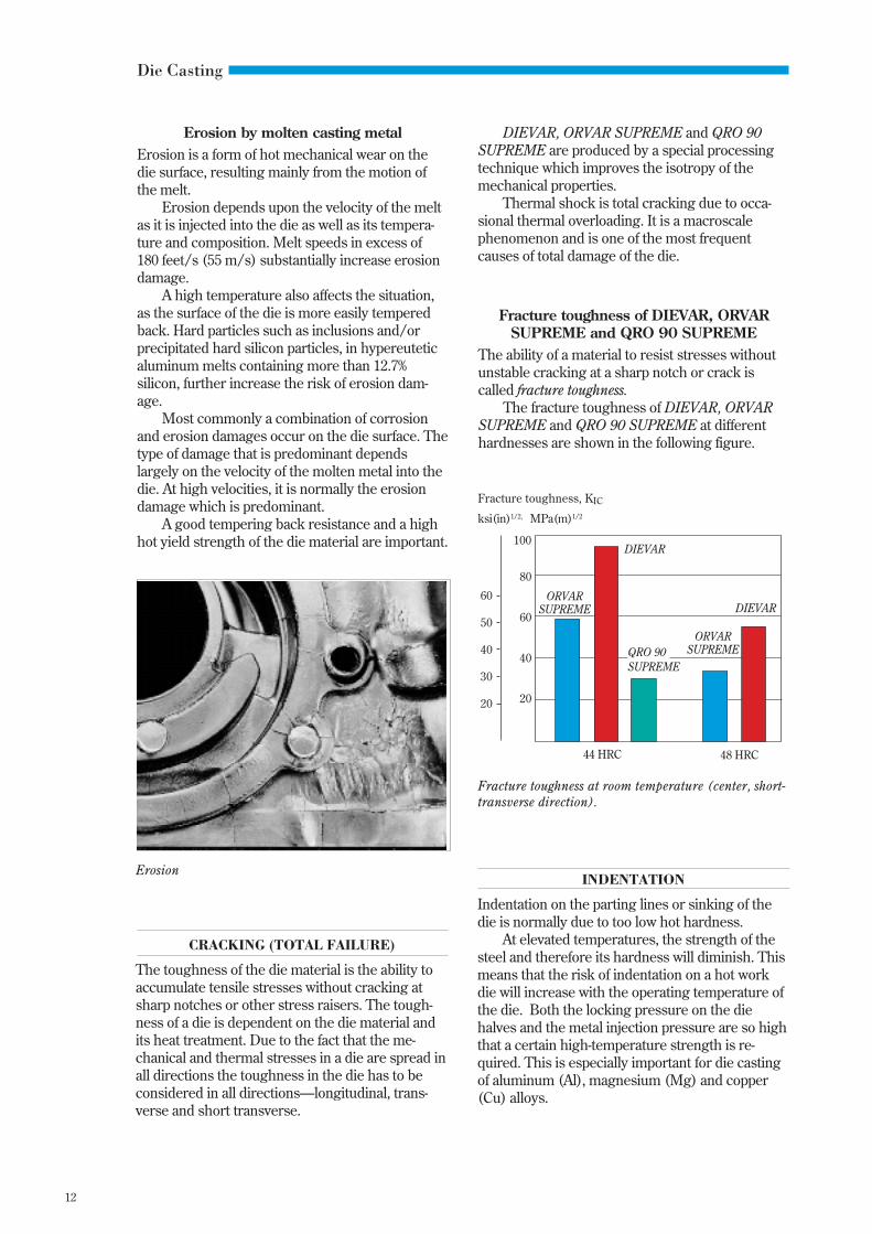
Fracture toughness of DIEVAR, ORVARSUPREME and QRO 90 SUPREME
The ability of a material to resist stresses withoutunstable cracking at a sharp notch or crack iscalled fracture toughness.
The fracture toughness of DIEVAR, ORVARSUPREME and QRO 90 SUPREME at differenthardnesses are shown in the following figure.
INDENTATION
Indentation on the parting lines or sinking of thedie is normally due to too low hot hardness.
At elevated temperatures, the strength of thesteel and therefore its hardness will diminish. Thismeans that the risk of indentation on a hot workdie will increase with the operating temperature ofthe die. Both the locking pressure on the diehalves and the metal injection pressure are so highthat a certain high-temperature strength is re-quired. This is especially important for die castingof aluminum (Al), magnesium (Mg) and copper(Cu) alloys.
Fracture toughness, KIC
ksi(in)1/2, MPa(m)1/2
100
80
60
40
20
44 HRC 48 HRC
Fracture toughness at room temperature (center, short-transverse direction).
CRACKING (TOTAL FAILURE)
The toughness of the die material is the ability toaccumulate tensile stresses without cracking atsharp notches or other stress raisers. The tough-ness of a die is dependent on the die material andits heat treatment. Due to the fact that the me-chanical and thermal stresses in a die are spread inall directions the toughness in the die has to beconsidered in all directions—longitudinal, trans-verse and short transverse.
Erosion
DIEVAR, ORVAR SUPREME and QRO 90SUPREME are produced by a special processingtechnique which improves the isotropy of themechanical properties.
Thermal shock is total cracking due to occa-sional thermal overloading. It is a macroscalephenomenon and is one of the most frequentcauses of total damage of the die.
ORVARSUPREME
ORVARSUPREME
DIEVAR
DIEVAR
QRO 90SUPREME
60
50
40
30
20

13
Die Casting
STEEL COST
DIE MAKING COST
PRODUCTION ANDMAINTENANCE COSTS
welding
scrap
preheating
lost production
heat treatment
delivery delays
adjustment
etc., etc...
TOOL COST
TOTALTOOLING
COST
repairs
“The Cost Iceberg”
Die EconomyThe drive for improved tooling economy hasresulted in the development of “premium quality”die steels.
As the tooling cost is in the order of 10 percent of the total cost of the finished aluminum diecast product, the validity of paying for premium diesteel quality resulting in increased tool life isobvious.
The most decisive factors that govern tool lifeare the die material, its heat treatment and the diecasting process control. The material in a diecasting die accounts for 5–15 per cent of the diecost while the heat treatment cost is about 5–10per cent. The picture below—The Cost Iceberg—shows the steel cost in relation to total toolingcosts.
In order to assure a good steel quality anumber of material specifications for die materialhave been developed during the last 20 years.Most of these contain requirements on chemicalanalysis, microcleanliness, microstructure, band-ing, grain size, hardness, mechanical propertiesand internal soundness (quality level).
One of the most advanced specifications forsteel acceptance criteria and heat treatment atpresent is the Premium Quality H13 Steel Accept-ance Criteria for Pressure Die Casting Dies # 207–97 released by the North American Die CastingAssociation (NADCA).
Further improvement of tooling economymust involve specifications on the heat treatmentof the die. This should be optimized to avoid anyexcessive dimensional changes or distortion butto produce the optimal combination of hardnessand toughness. The most critical factors are thehardening temperature and the cooling rate duringquenching.
Precautions like proper preheating of the dieas well as stress tempering will give a better dieeconomy.
Surface treatments are methods to protect thedie surface from corrosion/erosion and thermalfatigue.
New welding techniques have opened areasfor maintenance and repair welding, both import-ant ways to increase the die life.
Everyone involved in the chain—steel produ-cer, die manufacturer, heat treater and die caster—knows that there can be large variations in qualitylevel at every step of this process.
Optimum results can only be achieved bydemanding and paying for premium quality allalong the line.

14
Die Casting
DIEVAR A premium Cr-Mo-V-alloyed hot work die steel with good high temperaturestrength and excellent hardenability, toughness and ductility. Suitable for mediumto big dies in aluminum die casting. It meets and exceeds the requirements ofNADCA #207-97.
ORVAR SUPREME A premium Cr-Mo-V-alloyed hot work die steel Premium (H13) with good resis-tance to thermal fatigue. The steel is produced by a special melting and refiningtechnique and meets and exceeds the requirements of NADCA # 207–97.
QRO 90 SUPREME A premium hot work die steel with high hot yield strength and good temper resis-tance. Especially suited for die casting of copper, brass and for small inserts andcores in aluminum die casting.
IMPAX SUPREME A prehardened Ni-Cr-Mo-steel supplied at 300–341 HB suitable for die casting ofzinc, lead and tin. Also used as a holder material.
HOLDER A prehardened steel with very good machinability supplied at ~300 HB for clamp-ing and holding plates.
Hardness Analysis, %Uddeholm grade AISI HB C Si Mn S Cr Mo V Others
Die steelsDIEVAR – ~160 Cr-Mo-V alloyed hot work tool steel –
ORVAR SUPREME Premium ~180 0.39 1.0 0.4 max 5.2 1.4 0.9 –H13 0.0030
QRO 90 SUPREME – ~180 0.38 0.3 0.75 max 2.6 2.25 0.9 Microalloyed0.0030
IMPAX SUPREME P20 ~320 0.37 0.3 1.4 max 2.0 0.2 – Ni 1.0modified 0.010
Holder and clamping steelHOLDER 4140 ~300 A free-machining Cr-Mo-alloyed steel
modified
General description
Analysis
Product Program
Qualitative comparisons
Qualitative comparison of critical die steel properties.
Qualitative comparison of resistance to different die failures (the longer the bar, the better).
Uddeholm Heat Grossgrade checking cracking Erosion Indentation
Uddeholm Temper Hot yield Harden-grade resistance strength Ductility Toughness ability
DIEVAR
ORVAR SUPREME
QRO 90 SUPREME
DIEVAR
ORVAR SUPREME
QRO 90 SUPREME

15
Die Casting
Die Part Tin/Lead/Zinc Aluminum/Magnesium Copper, Brass
Clamping plates HOLDER HOLDER HOLDERHolder plates (prehardened) ~300 HB (prehardened) ~300 HB (prehardened) ~300 HB
IMPAX SUPREME IMPAX SUPREME IMPAX SUPREME(prehardened) ~320 HB (prehardened) ~320 HB (prehardened)~320 HB
Die inserts IMPAX SUPREME DIEVAR QRO 90 SUPREME~320 HB 44–50 HRC 40–46 HRCORVAR SUPREME** ORVAR SUPREME** ORVAR SUPREME**46–52 HRC 42–48 HRC 40–46 HRC
Fixed inserts ORVAR SUPREME** DIEVAR QRO 90 SUPREMECores 46–52 HRC 46–50 HRC 40–46 HRC
ORVAR SUPREME**44–48 HRCQRO 90 SUPREME42–48 HRC
Core pins ORVAR SUPREME** QRO 90 SUPREME* QRO 90 SUPREME46–52 HRC 44–48 HRC 42–46 HRC
Sprue parts ORVAR SUPREME**48–52 HRC
Nozzle STAVAX ESR40–44 HRCORVAR SUPREME**35–44 HRC
Ejector pins QRO 90 SUPREME QRO 90 SUPREME QRO 90 SUPREMEORVAR SUPREME** ORVAR SUPREME** ORVAR SUPREME**46–50 HRC (nitrided) 46–50 HRC (nitrided) 44–50 HRC (nitrided)
Plunger ORVAR SUPREME** ORVAR SUPREME** QRO 90 SUPREMEShot sleeve 42–46 HRC (nitrided) 42–48 HRC (nitrided) 42–46 HRC (nitrided)
QRO 90 SUPREME ORVAR SUPREME**42–48 HRC (nitrided) 42–46 HRC (nitrided)
1 Clamping plates2 Holder plates3 Die inserts4 Fixed inserts5 Cores6 Sprue bushing (nozzles)7 Sprue pin (Spreader)8 Ejector pins
Steel and Hardness Recommendations
1 2 23 3
48
5 67 1
* Surface treatment is recommended.** Where the standard H13 is considered adequate Uddeholm H13 may be substituted.