Embed Size (px)
Citation preview
Operation / Installation Instructions
No. 44.NCR.E3.04/11 NCR
DICKOW PUMPEN KG
Original Manual
NCR E3.04.11 2 of 51
Table of Contents Table of Contents ......................................................................................................................................... 2 1. General................................................................................................................................................. 4 2. Safety ................................................................................................................................................... 5
2.1 Designation of Warning Notices................................................................................................. 5 2.2 Intended use ................................................................................................................................ 6 2.3 Avoidance of foreseeable operating errors ................................................................................. 6 2.4 Qualification of personnel........................................................................................................... 7 2.5 Additional safety regulations ...................................................................................................... 7 2.6 Safety instructions for the operator / user ................................................................................... 7 2.7 Safety instructions for maintenance, inspection and assembly .................................................. 8 2.8 Non-observance of the instruction manual ................................................................................. 8 2.9 Notices on explosion protection.................................................................................................. 8
3. Description......................................................................................................................................... 10 3.1 General description ................................................................................................................... 10 3.2 Design code............................................................................................................................... 10 3.3 Classification of pump size / frame size ................................................................................... 10 3.4 Identification ............................................................................................................................. 11 3.5 Design ....................................................................................................................................... 12 3.6 Scope of supply......................................................................................................................... 12 3.7 Dimensions and Weights .......................................................................................................... 12
4. Handling / Storage / Disposal ............................................................................................................ 13 4.1 Handling.................................................................................................................................... 13 4.2 Storage / Preservation ............................................................................................................... 14 4.3 Return of pump ......................................................................................................................... 14 4.4 Disposal .................................................................................................................................... 15
5. Installation / Mounting ...................................................................................................................... 16 5.1 Safety Instructions .................................................................................................................... 16 5.2 Foundation ................................................................................................................................ 16 5.3 Installation of pump unit ........................................................................................................... 16 5.4 Piping ........................................................................................................................................ 17 5.5 Insulation .................................................................................................................................. 20 5.6 Coupling alignment................................................................................................................... 20 5.7 Alignment of pump and motor.................................................................................................. 22 5.8 Electrical connection of the pump unit ..................................................................................... 23
6. Commissioning / Decommissioning.................................................................................................. 25 6.1 Commissioning ......................................................................................................................... 25 6.2 Operating the pump................................................................................................................... 29 6.3 Impeller trimming ..................................................................................................................... 29 6.4 Operating limits ....................................................................................................................... 29 6.5 Switching off the pump............................................................................................................. 30 6.6 Decommissioning ..................................................................................................................... 31
7. Maintenance / Servicing / Inspection ................................................................................................ 32 7.1 Safety regulations...................................................................................................................... 32 7.2 Operating surveillance .............................................................................................................. 33 7.3 Drainage and Disposal .............................................................................................................. 35 7.4 Disassembly of pump unit ........................................................................................................ 35 7.5 Inspection.................................................................................................................................. 38 7.6 Assembly of pump unit ............................................................................................................. 38 7.7 Bolt torques............................................................................................................................... 41
Table of Contents
NCR E3.04.11 3 of 51
8. Troubleshooting................................................................................................................................. 42 9. Interchangeability .............................................................................................................................. 44
9.1 Frame size I............................................................................................................................... 44 9.2 Frame size II ............................................................................................................................. 45 9.3 Frame size III ............................................................................................................................ 46 9.4 Frame size IV............................................................................................................................ 47
10. Sectional drawings ........................................................................................................................ 48 10.1 Pump ......................................................................................................................................... 48 10.2 Mechanical seal......................................................................................................................... 49
11. Certificates .................................................................................................................................... 50 11.1 EC-Declaration of Conformity.................................................................................................. 50 11.2 Document of Compliance ......................................................................................................... 51
Table of Contents
NCR E3.04.11 4 of 51
1. General This instruction manual describes the proper and safe usage of the pump during all operating phases. The instruction manual does not consider local regulations. Adherence to those is the responsibility of the owner. The name tag states pump type and size, the most important operating data as well as the pump serial number. The serial number is a precise description of the pump unit and serves as identification for all following procedures. In the event of damage the Customer Service of Dickow Pumpen must immediately be informed in order to maintain guarantee claims. For installation of supplied interchangeable units, the respective subchapters of "Maintenance, Servicing, Inspection" must be observed. Applicable documents:
- Pump data sheet - Dimensional drawing - Sectional drawing - Parts lists - Sub-supplier documentation
1. General
NCR E3.04.11 5 of 51
2. Safety The manual includes basic instructions for installation, operation and maintenance. Only if these instructions are strictly observed, a safe handling of pump or pump unit is guaranteed and personal injury and material damage is avoided. All the safety instructions in this manual must be considered. This manual must be thoroughly reviewed and completely understood by the qualified personnel / operator before attempting assembly and start-up. The manual must consistently be available on site. Indications and plates attached to the pump must be followed and kept in legible condition.
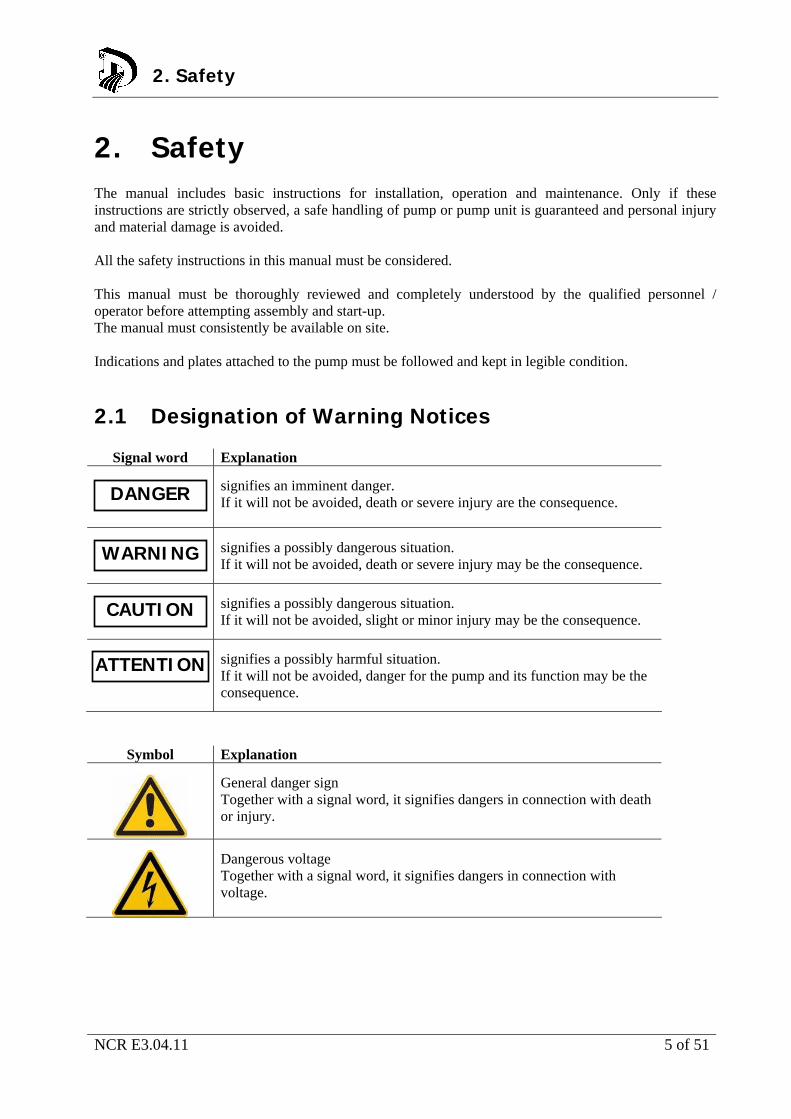
2.1 Designation of Warning Notices
Signal word Explanation
signifies an imminent danger. If it will not be avoided, death or severe injury are the consequence.
signifies a possibly dangerous situation. If it will not be avoided, death or severe injury may be the consequence.
signifies a possibly dangerous situation. If it will not be avoided, slight or minor injury may be the consequence.
signifies a possibly harmful situation. If it will not be avoided, danger for the pump and its function may be the consequence.
Symbol Explanation
General danger sign Together with a signal word, it signifies dangers in connection with death or injury.
Dangerous voltage Together with a signal word, it signifies dangers in connection with voltage.
2. Safety
DANGER
WARNING
CAUTION
ATTENTION
NCR E3.04.11 6 of 51
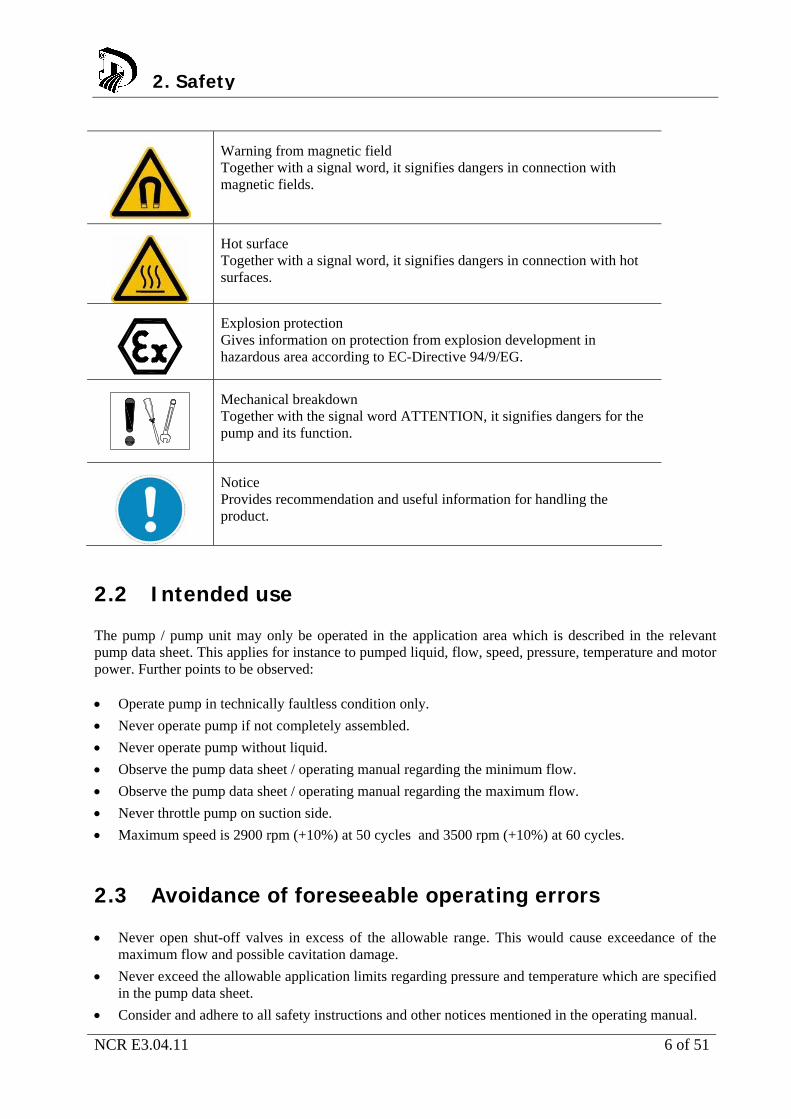
Warning from magnetic field Together with a signal word, it signifies dangers in connection with magnetic fields.
Hot surface Together with a signal word, it signifies dangers in connection with hot surfaces.
Explosion protection Gives information on protection from explosion development in hazardous area according to EC-Directive 94/9/EG.
Mechanical breakdown Together with the signal word ATTENTION, it signifies dangers for the pump and its function.
Notice Provides recommendation and useful information for handling the product.
2.2 Intended use The pump / pump unit may only be operated in the application area which is described in the relevant pump data sheet. This applies for instance to pumped liquid, flow, speed, pressure, temperature and motor power. Further points to be observed: Operate pump in technically faultless condition only.
Never operate pump if not completely assembled.
Never operate pump without liquid.
Observe the pump data sheet / operating manual regarding the minimum flow.
Observe the pump data sheet / operating manual regarding the maximum flow.
Never throttle pump on suction side.
Maximum speed is 2900 rpm (+10%) at 50 cycles and 3500 rpm (+10%) at 60 cycles.
2.3 Avoidance of foreseeable operating errors Never open shut-off valves in excess of the allowable range. This would cause exceedance of the
maximum flow and possible cavitation damage.
Never exceed the allowable application limits regarding pressure and temperature which are specified in the pump data sheet.
Consider and adhere to all safety instructions and other notices mentioned in the operating manual.
2. Safety
NCR E3.04.11 7 of 51
2.4 Qualification of personnel The personnel must possess the relevant qualification for assembly, operation, maintenance and inspection of the pump unit. Responsibility, competence and supervision must be strictly regulated by the owner. Skill of the personnel shall be improved by training. Training course can be held by the technical staff of Dickow Pumpen.
2.5 Additional safety regulations Besides the safety instructions mentioned in this manual, the following additional regulations apply: Accident prevention regulations
Explosion proof regulations
Safety regulations for handling hazardous materials
Applicable standards and laws
2.6 Safety instructions for the operator / user Protection against contact with hot and cold components must be provided by customer.
Coupling guard and hand guard on the pump / pump unit must not be removed during operation.
Pump must always be earth connected / grounded.
Protective equipment for personnel must be provided and used.
Toxic liquid leakage must be drained off safely, without endangering individuals and environment. Legal requirements must be observed.
Danger through electric energy must be excluded.
2. Safety
NCR E3.04.11 8 of 51
2.7 Safety instructions for maintenance, inspection and assembly Alteration works or modifications on the pump are only allowed after consulting Dickow Pumpen.
Only original parts or parts approved by Dickow shall be used.
Repairs on the pump / pump unit may only be done during shutdown.
The pump casing must have cooled down to ambient temperature.
The pump must be depressurized and drained.
Consider the procedure for decommissioning according to chapter 6.6.
Pumps handling products dangerous to health must be decontaminated according to chapter 4.4
Coupling guard and hand guard must be mounted again after completion of the works.
Works on the pump unit may be done only with disconnected electricity.
Secure the pump unit against unintentional switch-on.
2.8 Non-observance of the instruction manual Non-observance of this manual leads to loss of warranty and damage claims. Non-observance will involve the following risks: Endangering of individuals through electrical, thermal, mechanical and chemical impacts.
Danger through explosions.
Danger through breakdown of essential functions.
Endangering of environment through leakage of toxic liquids.
2.9 Notices on explosion protection Operation in explosive areas requires stringent attention to this
chapter.
Only pumps with “Ex”-identification are allowed to be used in explosive areas.
Pumps must be designated for this service in the pump data sheet.
Intended use must be guaranteed.
Inadmissible operating conditions must be avoided in any case.
Special conditions apply for operation in compliance with EC-Directive 94/9/EC (ATEX). The “Ex”-symbol shown here marks the chapters in this manual which require special attention.
2. Safety
DANGER
NCR E3.04.11 9 of 51
2.9.1 Surface temperature The highest surface temperatures are to be expected at the pump casing, the atmosphere sided seal ring of mechanical seal and in the area of antifriction bearings. The surface temperature at the pump casing is equal to the temperature of the pumped liquid. The surface of the bearing bracket must be uncovered. Insulation of the bearing bracket is not allowed. 2.9.2 Monitoring devices The pump may only be operated within the limit values given in the pump data sheet and on the name tag. In case the owner cannot guarantee for maintaining the operating limits, monitoring devices are requied. More information on monitoring devices can be inquired at DICKOW Pumpen.
2. Safety
NCR E3.04.11 10 of 51
3. Description 3.1 General description The heavy duty centrifugal pump is used in the oil and gas industry as well as in related industrial sectors where the requirements according to API 610 must be fulfilled
3.2 Design code Example: NCR i huh 32/210 A C2A1A1162
NCR pump type
i special design; e.g. i = inducer
huh material execution; e.g. huh = 1.7706 (carbon steel)
32 nominal width discharge flange [mm]
210 nominal impeller diameter [mm]
A scope of supply; e.g. A = bare shaft pump
C2A1A1162 shaft sealing; e.g. C2A1A1162 = mech.seal code acc. to API 682
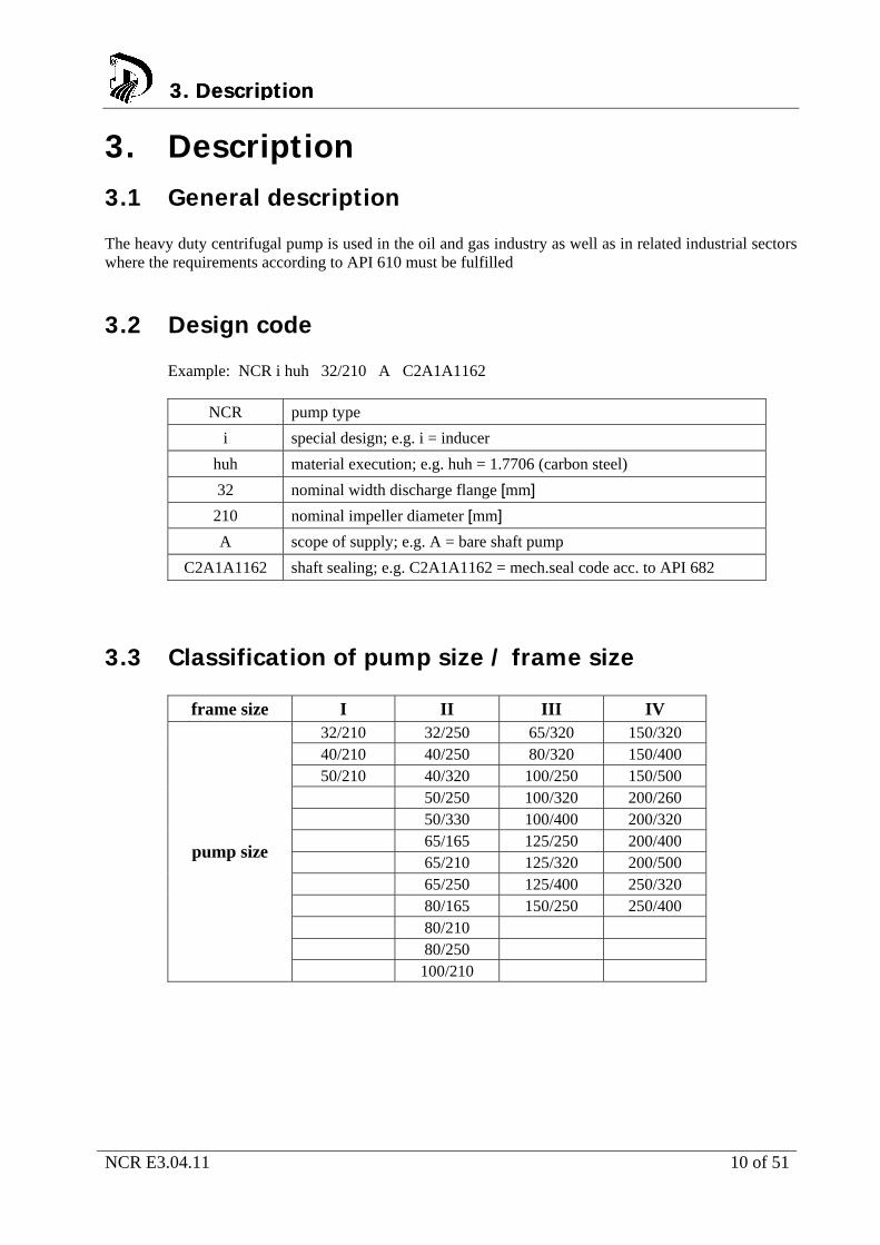
3.3 Classification of pump size / frame size
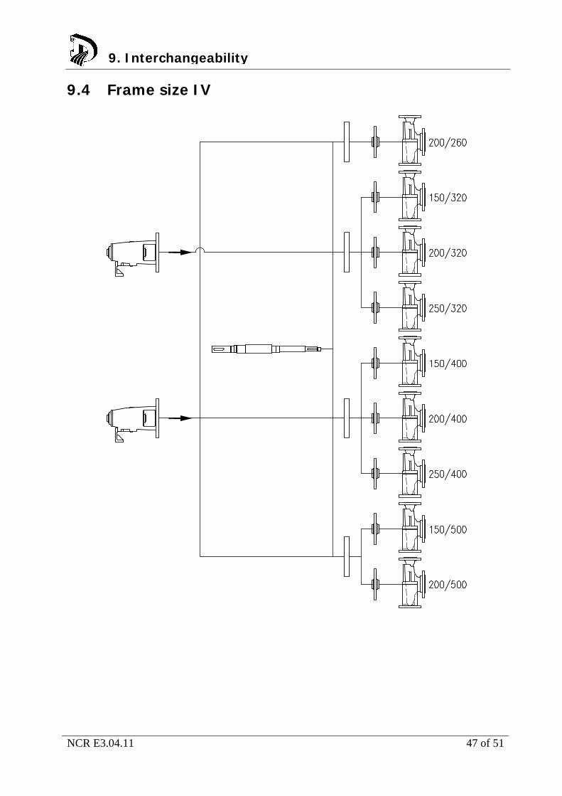
frame size I II III IV 32/210 32/250 65/320 150/320 40/210 40/250 80/320 150/400 50/210 40/320 100/250 150/500
50/250 100/320 200/260 50/330 100/400 200/320 65/165 125/250 200/400 65/210 125/320 200/500 65/250 125/400 250/320 80/165 150/250 250/400 80/210 80/250
pump size
100/210
3. Description 3. Description
NCR E3.04.11 11 of 51
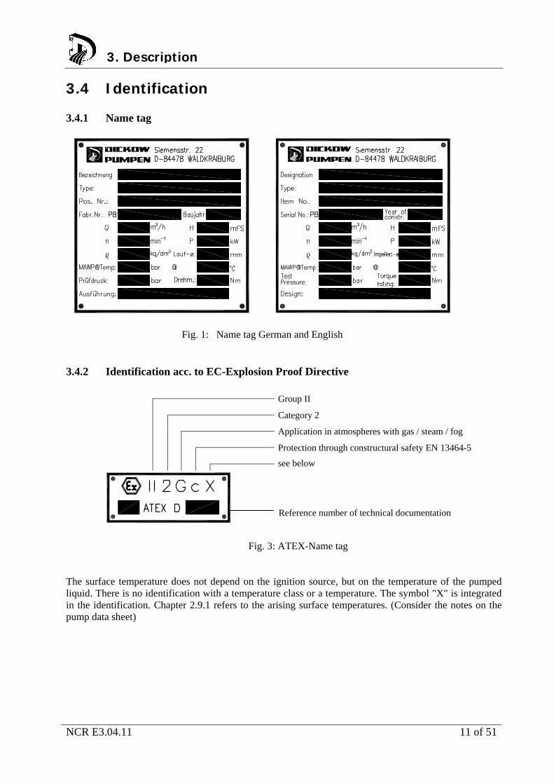
3.4 Identification 3.4.1 Name tag
Fig. 1: Name tag German and English 3.4.2 Identification acc. to EC-Explosion Proof Directive
Group II
Category 2
Application in atmospheres with gas / steam / fog
Protection through constructural safety EN 13464-5
see below
Reference number of technical documentation
Fig. 3: ATEX-Name tag
The surface temperature does not depend on the ignition source, but on the temperature of the pumped liquid. There is no identification with a temperature class or a temperature. The symbol "X" is integrated in the identification. Chapter 2.9.1 refers to the arising surface temperatures. (Consider the notes on the pump data sheet)
3. Description
NCR E3.04.11 12 of 51
3.5 Design Design
volute casing pump
horizontal installation
single stage
compliance with requirements of API 610
Pump casing
single volute / double volute (depending on pump size)
radially split
centerline mounted
Impeller
closed or open
back vanes, relief holes and / or injection slots for thrust load balance
Bearing
motor end: paired angular ball bearing as fixed bearing
pump end: cylinder roller bearing
oil lubrication
Shaft sealing
Cartridge seal acc. to API 682
3.6 Scope of supply Depending on the pump execution, the following items belong to the scope of supply: Pump
Elastic coupling with spacer piece
Coupling guard
Welded base frame of sturdy design
Drive motor
Special accessories if required
3.7 Dimensions and Weights Dimensions and weights can be taken from the foundation plan / dimensional drawing.
3. Description 3. Description
NCR E3.04.11 13 of 51
4. Handling / Storage / Disposal
4.1 Handling
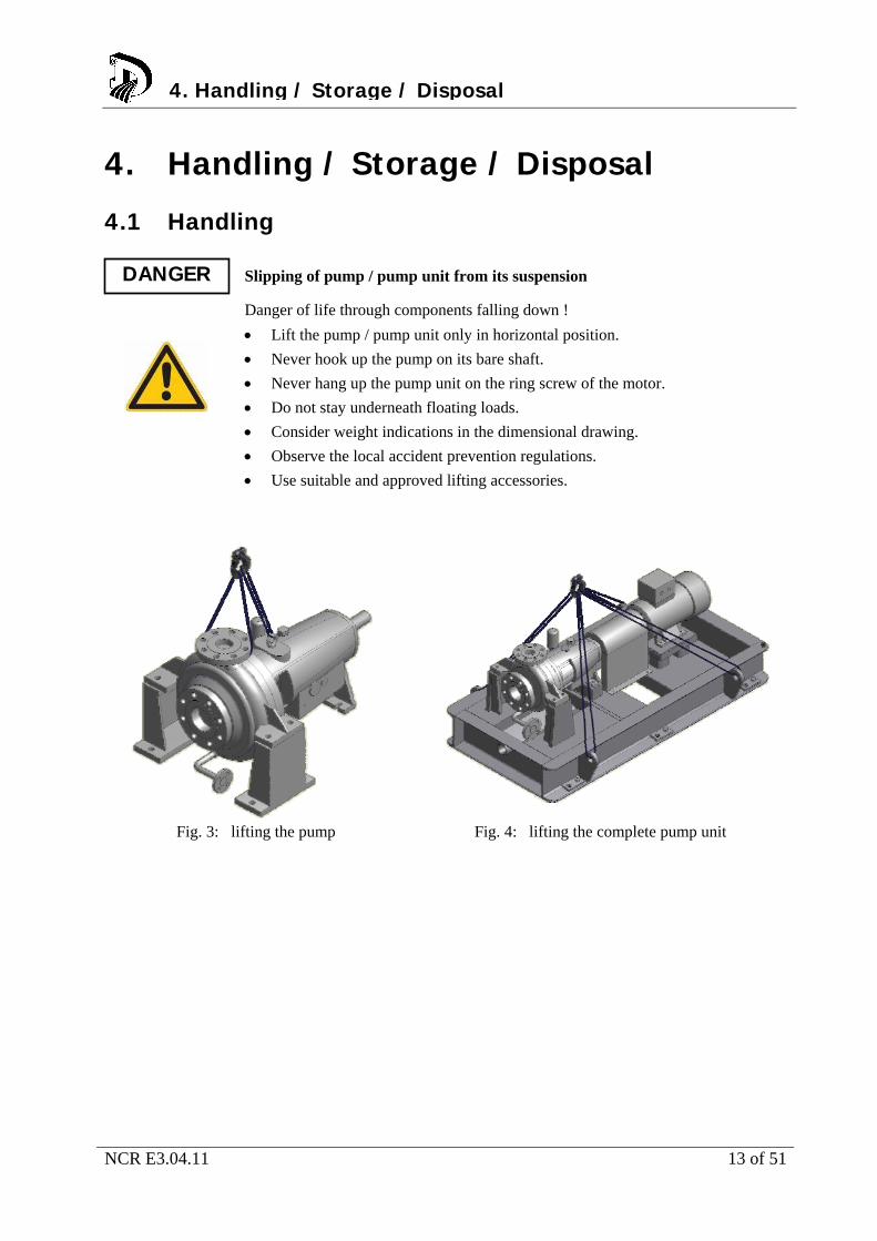
Slipping of pump / pump unit from its suspension
Danger of life through components falling down !
Lift the pump / pump unit only in horizontal position.
Never hook up the pump on its bare shaft.
Never hang up the pump unit on the ring screw of the motor.
Do not stay underneath floating loads.
Consider weight indications in the dimensional drawing.
Observe the local accident prevention regulations.
Use suitable and approved lifting accessories.
Fig. 3: lifting the pump Fig. 4: lifting the complete pump unit
DANGER
4. Handling / Storage / Disposal
NCR E3.04.11 14 of 51
4.2 Storage / Preservation Damage during storage through moisture or dirt.
Corrosion and / or contamination of the pump !
Outside storage requires a watertight cover over pump or over packed pump and accessories.
Wetted, contaminated or damaged openings and joints.
Leakage or damage of the pump !
Plugged openings should be uncovered only during installation.
The following measures are recommended for storage of the pump / pump unit: Store the pump in a sheltered dry place with constant air humidity.
Turn the shaft manually once a month.
New pumps of material GGG (ductile iron) and ferritic cast steel are covered inside with anti-corrosive agent and dewatering-fluid. The maximum dry storage period is 12 months. For storing a pump that has been in operation already, consider chapter 6.6.
4.3 Return of pump Drain the pump properly considering chapter 7.3.
Rinse and clean the pump in general, especially when handling dangerous, explosive, hot or other risky liquids.
A Document of Compliance completely filled in must always be attached to the pump. Refer to chapter 11.2.
If required, a Document of Compliance can be downloaded under www.dickow.de.
http://www.dickow.de/unbedenk-en.pdf
4. Handling / Storage / Disposal
ATTENTION
ATTENTION
NOTE
NCR E3.04.11 15 of 51
4.4 Disposal
Liquids dangerous to health
Danger for individuals and environment !
Collect and dispose rinsing water and residual liquid.
Wear protective clothing and face mask.
Consider the legal regulations for disposal of liquids dangerous to health.
1. Disassemble pump / pump unit.
2. Collect grease and oil.
3. Separate pump materials
4. Dispose according to the local regulations.
WARNING
4. Handling / Storage / Disposal
NCR E3.04.11 16 of 51
5. Installation / Mounting
5.1 Safety Instructions Improper installation in explosive area
Danger of explosion !
Consider the local applicable explosion proof regulations.
Consider indications on the pump data sheet and on the name tag of pump and motor.
5.2 Foundation Installation on weak and unstable foundations
Personal injury and material damage !
Consider sufficient concrete strength (minimum class XO) of the foundation acc. to DIN 1045.
Place the pump unit on hardened foundation only.
Place the pump unit on level and even surfaces only.
Consider weight indications of dimensional drawing.
5.3 Installation of pump unit 5.3.1 Installation on foundation 1. Place the pump unit on the foundation and align it with a water-level.
Allowable deviation: 0,2 mm/m
2. Insert shims for height compensation. Always insert them both-sided near the foundation bolts between baseplate and foundation.
3. If the space between the foundation bolts is > 600 mm, insert additional shims in the middle between the foundation bolts.
4. All shims must seat solidly.
5. Hook the foundation bolts into the provided bore.
6. Concrete the foundation bolts.
7. Align the base plate after concrete has hardened.
8. Tighten the foundation bolts evenly.
9. Pour the base plate with vibration-free concrete of normal graining with a water-cement-value (W/Z-value) ≤ 0,5. Provide a pourable consistency by using a mobile solvent. Cure of concrete according to DIN 1045.
DANGER
5. Installation / Mounting5. Installation / Mounting
WARNING
5. Installation / Mounting

NCR E3.04.11 17 of 51
5.4 Piping
Exceedance of the allowable loads at the pump flanges
Danger to life from leaking hot, toxic, caustic or flammable liquids.
Do not use the pump as an anchor point for piping.
Support piping before the pump and connect it stress-free.
Consider allowable flange forces and moments according to chapter 5.4.2.
Compensate expansion of the piping in case of high temperatures.
5. Installation / Mounting
DANGER
NCR E3.04.11 18 of 51
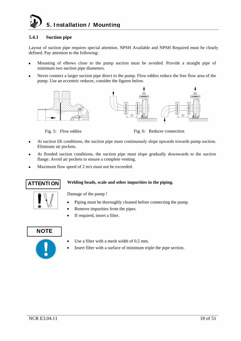
5.4.1 Suction pipe Layout of suction pipe requires special attention. NPSH Available and NPSH Required must be clearly defined. Pay attention to the following: Mounting of elbows close to the pump suction must be avoided. Provide a straight pipe of
minimum two suction pipe diameters.
Never connect a larger suction pipe direct to the pump. Flow eddies reduce the free flow area of the pump. Use an eccentric reducer, consider the figures below.
Fig. 5: Flow eddies
Fig. 6: Reducer connection
At suction lift conditions, the suction pipe must continuously slope upwards towards pump suction. Eliminate air pockets.
At flooded suction conditions, the suction pipe must slope gradually downwards to the suction flange. Avoid air pockets to ensure a complete venting.
Maximum flow speed of 2 m/s must not be exceeded.
Welding beads, scale and other impurities in the piping.
Damage of the pump !
Piping must be thoroughly cleaned before connecting the pump.
Remove impurities from the pipes.
If required, insert a filter.
Use a filter with a mesh width of 0,5 mm.
Insert filter with a surface of minimum triple the pipe section.
5. Installation / Mounting
ATTENTION
NOTE
NCR E3.04.11 19 of 51
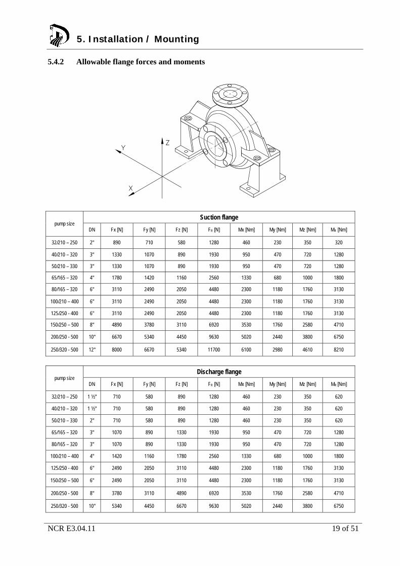
5.4.2 Allowable flange forces and moments
Suction flange pump size
DN Fx [N] Fy [N] Fz [N] FR [N] Mx [Nm] My [Nm] Mz [Nm] MR [Nm]
32/210 – 250 2" 890 710 580 1280 460 230 350 320
40/210 – 320 3" 1330 1070 890 1930 950 470 720 1280
50/210 – 330 3" 1330 1070 890 1930 950 470 720 1280
65/165 – 320 4" 1780 1420 1160 2560 1330 680 1000 1800
80/165 – 320 6" 3110 2490 2050 4480 2300 1180 1760 3130
100/210 – 400 6" 3110 2490 2050 4480 2300 1180 1760 3130
125/250 - 400 6" 3110 2490 2050 4480 2300 1180 1760 3130
150/250 – 500 8" 4890 3780 3110 6920 3530 1760 2580 4710
200/250 - 500 10" 6670 5340 4450 9630 5020 2440 3800 6750
250/320 - 500 12" 8000 6670 5340 11700 6100 2980 4610 8210
Discharge flange
pump size DN Fx [N] Fy [N] Fz [N] FR [N] Mx [Nm] My [Nm] Mz [Nm] MR [Nm]
32/210 – 250 1 ½" 710 580 890 1280 460 230 350 620
40/210 – 320 1 ½" 710 580 890 1280 460 230 350 620
50/210 – 330 2" 710 580 890 1280 460 230 350 620
65/165 – 320 3" 1070 890 1330 1930 950 470 720 1280
80/165 – 320 3" 1070 890 1330 1930 950 470 720 1280
100/210 – 400 4" 1420 1160 1780 2560 1330 680 1000 1800
125/250 - 400 6" 2490 2050 3110 4480 2300 1180 1760 3130
150/250 – 500 6" 2490 2050 3110 4480 2300 1180 1760 3130
200/250 - 500 8" 3780 3110 4890 6920 3530 1760 2580 4710
250/320 - 500 10" 5340 4450 6670 9630 5020 2440 3800 6750
5. Installation / Mounting
NCR E3.04.11 20 of 51
The pumps can tolerate double nozzle forces and moments as required by API 610.
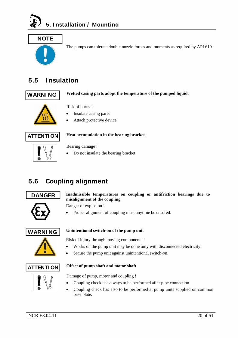
5.5 Insulation Wetted casing parts adopt the temperature of the pumped liquid.
Risk of burns !
Insulate casing parts
Attach protective device
Heat accumulation in the bearing bracket
Bearing damage !
Do not insulate the bearing bracket
5.6 Coupling alignment Inadmissible temperatures on coupling or antifriction bearings due to
misalignment of the coupling
Danger of explosion !
Proper alignment of coupling must anytime be ensured.
Unintentional switch-on of the pump unit
Risk of injury through moving components !
Works on the pump unit may be done only with disconnected electricity.
Secure the pump unit against unintentional switch-on.
Offset of pump shaft and motor shaft
Damage of pump, motor and coupling !
Coupling check has always to be performed after pipe connection.
Coupling check has also to be performed at pump units supplied on common base plate.
NOTE
5. Installation / Mounting
WARNING
ATTENTION
ATTENTION
WARNING
DANGER

NCR E3.04.11 21 of 51
Fig. 7: Angular and radial misalignment of couplings
Fig. 8: Coupling alignment 1. Dismantle coupling guard.
2. Loosen support foot.
3. Place a straight edge (1) axially across the coupling half.
4. Possible radial displacement ∆Kr becomes visible as a light gap. Better: Determine the radial misalignment by measuring the distances A and B at three points staggered by 120°. The coupling is aligned correctly if the distance to the shaft is identical at all points.
5. Check the distance s1 circularly between the coupling halves. The coupling is aligned correctly if the distance is circularly identical.
6. Concerning the allowable deviation ∆s1 and ∆Kr of both coupling halves, refer to the instruction manual of the coupling manufacturer !
7. Mount the support foot.
8. Mount the coupling guard.
5. Installation / Mounting
NCR E3.04.11 22 of 51
5.7 Alignment of pump and motor Exposed rotating coupling
Risk of injury through rotating shaft !
Operate the pump unit only with coupling guard.
Select the coupling guard according to corresponding standards.
Ignition hazard through friction sparks
Danger of explosion !
Use non-sparking material for coupling guard only to exclude flying sparks in case of contact.
Consider EN 13463-1.
After the pump unit is installed and piping is connected, check the coupling alignment and realign motor if necessary. Use shims for height compensation. 1. Dismantle coupling guard.
2. Check coupling alignment. Consider chapter 5.6.
3. Loosen hold down bolts of motor.
4. Place shims under the motor feet for height compensation.
5. Tighten hold down bolts of motor.
6. Check function of coupling / shaft. The coupling must easily be turnable by hand.
7. Mount the coupling guard.
8. Check the space between coupling and coupling guard.
5. Installation / Mounting
WARNING
DANGER
NCR E3.04.11 23 of 51
5.8 Electrical connection of the pump unit Improper electrical installation
Danger of explosion !
Electrical installation requires additionally observance of IEC 60079-14.
Explosion proof motors shall be connected through motor protection switch only
Working on the pump unit by unqualified personnel
Danger to life through electric shock !
Electrical connection must be performed by qualified electrician only.
Regulations IEC 30364 and IEC 60079 must be considered.
Incorrect power connection
Short circuit !
Adhere to connection conditions of local energy supply companies.
Proceedings:
1. Check for compliance of the available supply voltage with the indications on the motor name tag.
2. Select suitable connection method.
3. Check for identical rotating direction of motor and pump. Consider the rotating direction arrow of the pump !
Observe the instruction manual of the motor !
5. Installation / Mounting
DANGER
DANGER
WARNING
NOTE

NCR E3.04.11 24 of 51
5.8.1 Checking rotating direction
Temperature rise through parts touching each other
Danger of explosion !
Never check rotating direction with dry pump.
Disconnect the pump for checking rotating direction.
Wrong rotating direction of motor and pump
Damage of the pump !
Consider the rotating direction arrow on the pump.
1. Start motor briefly. Note rotating direction of the motor.
2. Rotating direction of the motor must comply with the rotating direction arrow on the pump.
3. In case of wrong rotating direction, change the cables in the motor terminal box.
DANGER
ATTENTION
5. Installation / Mounting
NCR E3.04.11 25 of 51
6. Commissioning / Decommissioning 6.1 Commissioning The following points must be checked prior to start-up; The pump unit is correctly electronically connected to all relevant protective devices.
The pump is filled with liquid.
Rotating direction has been checked.
All additional connections are connected and fully functional.
Lubricants are checked.
After a longer standstill period, the measures mentioned in chapter 7 "Maintenance/Servicing/Inspection" must be considered and performed.
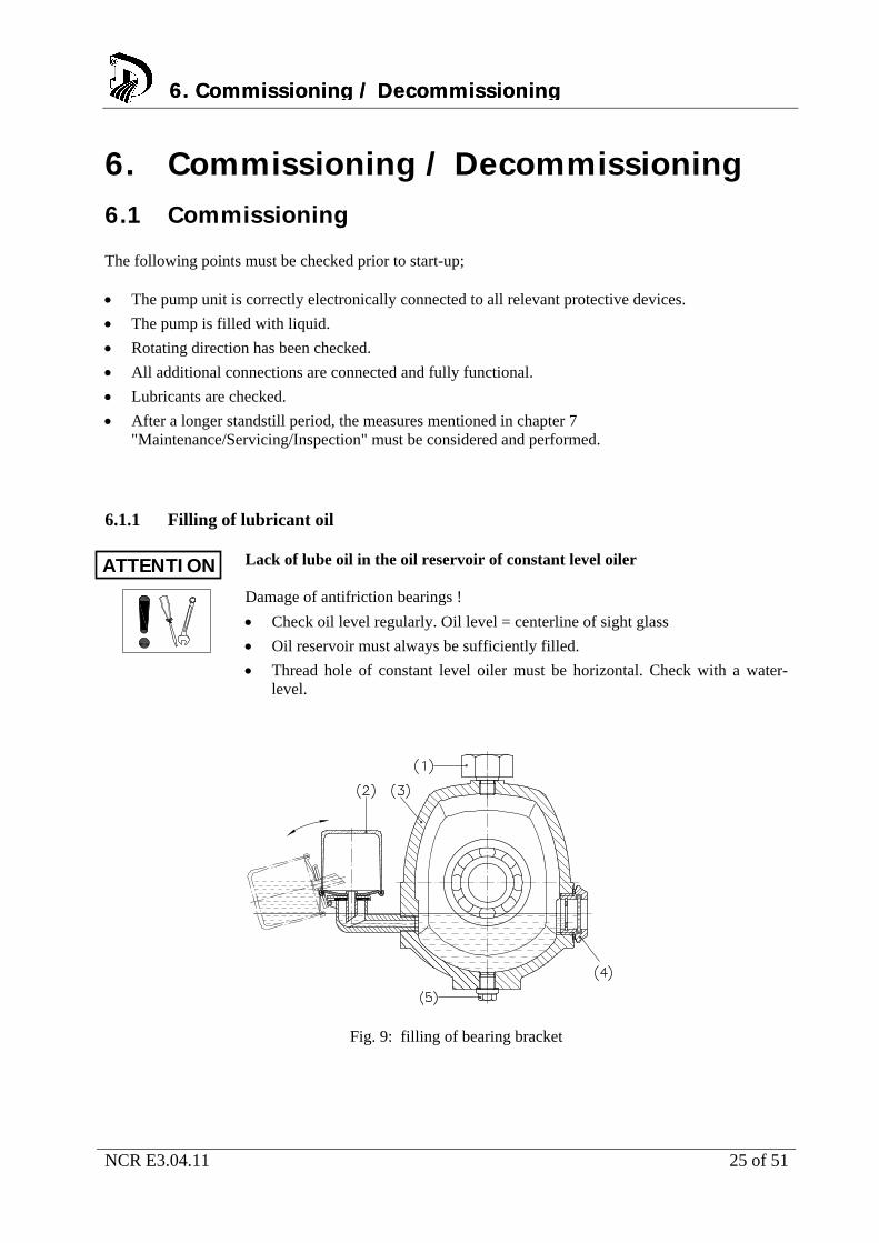
6.1.1 Filling of lubricant oil Lack of lube oil in the oil reservoir of constant level oiler
Damage of antifriction bearings !
Check oil level regularly. Oil level = centerline of sight glass
Oil reservoir must always be sufficiently filled.
Thread hole of constant level oiler must be horizontal. Check with a water-level.
Fig. 9: filling of bearing bracket
6. Commissioning / Decommissioning6. Commissioning / Decommissioning
ATTENTION

NCR E3.04.11 26 of 51
1. Unscrew vent plug (1).
2. Fold down the constant level oiler (2) – away from bearing bracket (3) – and hold it tight.
3. Fill in the oil through the vent plug bore (1) until the filling level reaches the connection pipe of the constant level oiler (2)
4. Fill up the oil reservoir to the maximum.
5. Fold back the constant level oiler (2) to its original position.
6. Screw in the vent plug (1).
7. Check the oil level in the oil reservoir of the constant level oiler (4) after a few minutes. Oil level = centerline of sight glass. If necessary, repeat steps 4 to 6.
Exceeding oil level causes temperature increase or oil leakage.
For filling quantity and oil quality refer to chapter 7.2.2. 6.1.2 Filling and venting the pump Formation of explosive atmosphere inside the pump
Danger of explosion !
The pump must permanently be filled with liquid.
Appropriate monitoring measures must be provided.
1. Vent and fill up pump and suction pipe with liquid.
Pump is selfventing.
2. Open shut-off valve in suction pipe completely
3. Open all additional connections completely (e.g. external circulation, external flush)
NOTE
6. Commissioning / Decommissioning
DANGER
NCR E3.04.11 27 of 51
6.1.4 Design with heating jacket Pump casing and intermediate casing with heating jacket. Permissible heating agent:
Hot water
Steam
Heat transfer oil
Pressure- and temperature limits:
tmax = 200°C
pmax = 25 bar
Elevated surface temperature
Danger of explosion !
Consider the allowable temperature class.
Lack of heating fluid
Damage of the pump !
Provide sufficient amount of heating fluid.
Heating period too short
Damage of the pump !
Consider a sufficient heating period of the pump (approx. 2 hours)
Check free rotation of the pump shaft.
Exceedance of the allowable heating fluid temperature
Leak of pumped liquid or heating agent !
Consider the application limits for pressure and temperature.
ATTENTION
ATTENTION
ATTENTION
ATTENTION
6. Commissioning / Decommissioning
NCR E3.04.11 28 of 51
6.1.4 Shaft sealing The pump is supplied with shaft sealing. If a fluid reservoir is foreseen, it must be filled according to the reservoir manual. If double mechanical seals are provided, a barrier pressure supply must be connected prior to starting the pump, following the instruction manual of reservoir respectively mechanical seal. In case of external flush, the pump must be flushed with the quantities and pressures as stated in the pump data sheet respectively in the dimensional drawing. 6.1.5 Starting the pump Exceedance of allowable pressure- and temperature limits
Danger of explosion ! Leakage of hot or toxic liquid
Never operate pump with closed shut-off valves in suction and/or discharge pipe.
Start-up pump unit only against partially opened shut-off valve on discharge side.
Elevated temperature through dry run
Danger of explosion !
Never operate pump in empty condition.
Always fill up pump properly.
Operate pump only within the allowable operating range.
1. Open shut-off valve completely in suction pipe
2. Open shut-off valve partially in discharge pipe
3. Switch on the motor.
4. When the pressure gauge indicates pressure, open shut-off valve on discharge side until the duty point is reached.
5. When the operating temperature is reached, check coupling alignment and realign if necessary.
6.1.6 Inspection of shaft sealing A mechanical seal is a dynamical seal and – due to physical and technical reasons – never leakage free. Design, tolerances, operating conditions, smoothness etc. determine the quantity of leakage. Leakage may increase during normal running-in of the sliding faces but will return to normal value after sufficient running time. If this should not be the case, the mechanical seal must be shut down, dismantled and inspected.
6. Commissioning / Decommissioning6. Commissioning / Decommissioning
DANGER
DANGER
NCR E3.04.11 29 of 51
6.2 Operating the pump High surface temperatures through hot liquids
Risk of burns !
Avoid touching the pump surface.
Wear protective clothing.
Abnormal noises, vibrations, temperatures or leakage
Damage of the pump !
Switch off the pump immediately.
Only restart the pump unit after cause of trouble has been eliminated.
6.3 Impeller trimming The impellers are hydraulically balanced in order to reduce thrust load. Additional to the wear rings, thrust load balance is done individually or in combination with
Back vanes
Balancing holes
Injection slots
Impeller diameter can be trimmed within the range that is shown in the performance curve.
6.4 Operating limits Exceedance of operating limits regarding pressure, temperature and speed
Danger of explosion ! Leaking hot or toxic liquid !
Maintain the allowable service conditions specified in the pump data sheet.
Avoid operation against closed shut-off valve.
Never operate pump at a temperature higher than specified in the pump data sheet.
6.4.1 Flow rate If not stated otherwise in the pump data sheet, the following applies: Qmin = 0,25 x Qopt
Qmax = 1,2 x Qopt
WARNING
ATTENTION
6. Commissioning / Decommissioning6. Commissioning / Decommissioning
DANGER

NCR E3.04.11 30 of 51
6.4.2 Switching frequencies Elevated surface temperature of the motor
Danger of explosion !
When using explosion proof motors, consider the information in the motor manual regarding switching frequencies.
The switching frequencies are defined by the maximum temperature rise of the motor and depend on the power reserve of the motor during operation and on the starting conditions.
Read instruction manual of motor manufacturer !
6.4.3 Abrasive liquids or solids If products containing abrasives or solids are handled, increased wear is to be expected. The inspection intervals in this regard must be shorter than the usual ones.
6.5 Switching off the pump 1. Keep shut-off valve in suction pipe open.
2. Close shut-off valve in discharge pipe.
3. Switch off the motor and watch for steady run down.
In case a non-return valve is installed in the discharge pipe, the shut-off valve can remain open. A counter pressure must be available.
For a longer standstill period, the following must be observed: Liquids which tend to polymerization, crystallization or solidification, must be drained completely.
If required, rinse the pump with a suitable liquid.
Close shut-off valve in the suction pipe.
Flush connections must be closed.
NOTE
6. Commissioning / Decommissioning
DANGER
6. Commissioning / Decommissioning
NOTE
NCR E3.04.11 31 of 51
6.6 Decommissioning The pump unit remains in the piping:
Provide sufficient amount of liquid for the test runs.
Switch on the pump unit regularly monthly or quarterly.
The pump unit will be dismantled and stored:
Empty the pump properly.
Observe the safety instructions acc. to chapter 7.1 / 7.3.
Spray the inside of the pump casing with preservation agent. Not required for stainless steel pumps.
Spray preservation agent through suction and discharge flange.
Plug suction and discharge flanges, e.g. with plastic caps.
Lubricate all unpainted outside surfaces of the pump with oil and grease free of silicone. Not required for stainless steel pumps.
Pay attention to additional notes in chapter 4.2.
6. Commissioning / Decommissioning
NCR E3.04.11 32 of 51
7. Maintenance / Servicing / Inspection 7.1 Safety regulations Improper maintained pump unit
Danger of explosion !
Maintain the pump unit regularly
Establish a maintenance schedule
Unintentional switching-on of the pump unit
Risk of injury through moving components !
Works on the pump unit may be done only at disconnected electricity.
Secure the pump unit against unintentional switch-on.
Hot liquids
Risk of injury!
Let the pump unit cool down to ambient temperature.
Liquids dangerous to health
Risk of injury !
Consider legal requirements.
Take safety measures for individuals and environment when draining the pumped liquid.
Decontaminate the pumps.
The user must assure that maintenance, inspection and assembly is performed by qualified personnel. These persons must have studied this operating manual comprehensively. A maintenance schedule needs a minimum of effort and may avoid expensive repairs. Any use of force on the pump unit must be avoided.
DANGER
WARNING
WARNING
WARNING
7. Maintenance / Servicing / Inspection
NCR E3.04.11 33 of 51
7.2 Operating surveillance Elevated surface temperature through hot running antifriction bearings
Danger of explosion ! Fire hazard !
Check antifriction bearings regularly for running noise.
Check the lubricant level regularly.
Wear caused by dry run
Damage of the pump !
Never operate an empty pump.
Never close the shut-off valve in suction pipe during operation.
Exceedance of the allowable liquid temperature
Damage of the pump !
Operation against closed discharge valve is not allowed.
Consider the temperature indications in the pump data sheet.
The following requires regular checking during operation: The pump must always run steady and vibration-free.
Check antifriction bearings for running noise. Vibrations, noises and increased power consumption are signs of wear.
Check the elastic elements of the coupling.
Clean the filter in the suction pipe regularly.
DANGER
ATTENTION
ATTENTION
7. Maintenance / Servicing / Inspection
NCR E3.04.11 34 of 51
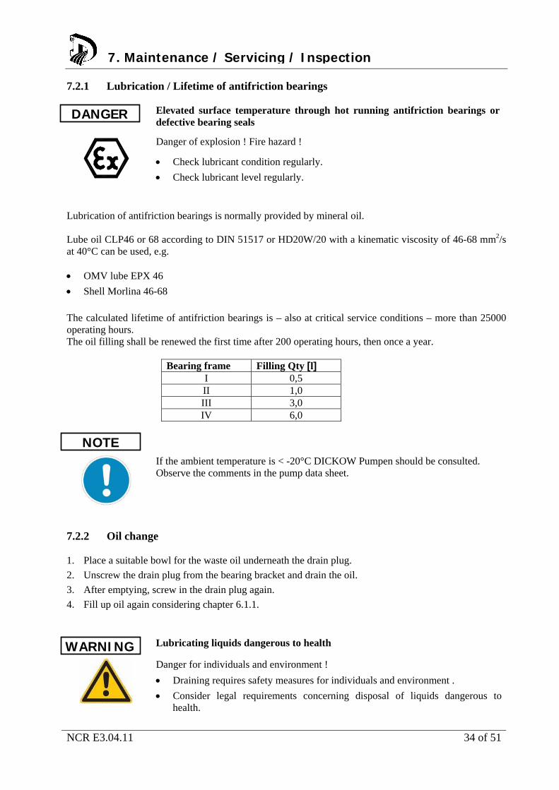
7.2.1 Lubrication / Lifetime of antifriction bearings Elevated surface temperature through hot running antifriction bearings or
defective bearing seals
Danger of explosion ! Fire hazard !
Check lubricant condition regularly.
Check lubricant level regularly.
Lubrication of antifriction bearings is normally provided by mineral oil. Lube oil CLP46 or 68 according to DIN 51517 or HD20W/20 with a kinematic viscosity of 46-68 mm2/s at 40°C can be used, e.g. OMV lube EPX 46
Shell Morlina 46-68
The calculated lifetime of antifriction bearings is – also at critical service conditions – more than 25000 operating hours. The oil filling shall be renewed the first time after 200 operating hours, then once a year.
Bearing frame Filling Qty [l] I 0,5 II 1,0 III 3,0 IV 6,0
If the ambient temperature is < -20°C DICKOW Pumpen should be consulted. Observe the comments in the pump data sheet.
7.2.2 Oil change 1. Place a suitable bowl for the waste oil underneath the drain plug.
2. Unscrew the drain plug from the bearing bracket and drain the oil.
3. After emptying, screw in the drain plug again.
4. Fill up oil again considering chapter 6.1.1.
Lubricating liquids dangerous to health
Danger for individuals and environment !
Draining requires safety measures for individuals and environment .
Consider legal requirements concerning disposal of liquids dangerous to health.
7. Maintenance / Servicing / Inspection
DANGER
NOTE
WARNING

NCR E3.04.11 35 of 51
7.3 Drainage and Disposal Pumped liquids dangerous to life
Endangering for individuals and environment !
Collect flushing liquid and possible residual liquid and dispose it.
Wear protective clothing and face masks.
Consider legal requirements concerning disposal of liquids.
Drainage of pumped liquids through the drain plugs at the casing, through a connected shut-off valve or through a flange. Mode of drainage and position can be taken from the dimensional drawing !
7.4 Disassembly of pump unit 7.4.1 General instructions Pay attention to safety instructions of chapter 7.1.
Working on the motor requires observance of the documentation provided by the motor manufacturer.
Consider the sectional drawings when disassembling.
In case of damage, our service department can be contacted.
Working on the pump unit without sufficient preparation
Risk of injury !
Switch off the pump unit properly.
Close shut-off valves on suction and discharge side.
Drain and depressurize the pump.
Flush connections must be closed.
Let the pump unit cool down to ambient temperature.
7. Maintenance / Servicing / Inspection
WARNING
DANGER
7. Maintenance / Servicing / Inspection
NCR E3.04.11 36 of 51
7.4.2 Removal of driver 5. Disconnect the motor.
6. Remove coupling guard.
7. Remove the hold down bolts of the motor from the baseplate.
8. Decouple pump and motor by displacing the motor.
Tilting the motor
Squeezing of hands and feet !
Secure the motor by lifting or bracing.
If pump units are equipped with spacer type couplings, the motor can remain bolted to the baseplate while dismantling the interchangeable unit.
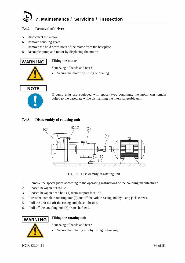
7.4.3 Disassembly of rotating unit
Fig. 10: Disassembly of rotating unit
1. Remove the spacer piece according to the operating instructions of the coupling manufacturer
2. Loosen hexagon nut 920.2.
3. Loosen hexagon head bolt (1) from support foot 183.
4. Press the complete rotating unit (2) out off the volute casing 102 by using jack screws.
5. Pull the unit out off the casing and place it beside.
6. Pull off the coupling hub (3) from shaft end.
Tilting the rotating unit
Squeezing of hands and feet !
Secure the rotating unit by lifting or bracing.
WARNING
NOTE
WARNING
7. Maintenance / Servicing / Inspection
NCR E3.04.11 37 of 51
7.4.4 Disassembly of impeller The works according to chapter 7.4.3 are completed. 1. Clamp the complete unit in vertical position in a jaw chuck.
2. Loosen the impeller nut 922 (right hand thread).
3. Pull off the impeller from pump shaft.
4. Remove key 940.1.
7.4.5 Disassembly of shaft sealing The works according to chapter 7.4.4 are completed. 1. If available, remove inner hexagon cap screw 914.1 and press the packing ring 457 out off the
intermediate casing 113. 2. Remove hexagon nut 920.5.
3. Press the intermediate casing 113 out off its centring.
4. Pull off the intermediate ring 509 from pump shaft.
5. Attach assembly gauges to the mechanical seal.
6. Loosen grub screws and pull off the complete seal unit 433 from pump shaft.
7.4.6 Disassembly of antifriction bearings The works according to chapter 7.4.5 are completed. 1. Loosen inner hexagon cap screws 914.6 and pull off bearing cover 360.2 together with labyrinth
seal 430.2. 2. Loosen inner hexagon cap screws 914.5 and pull off bearing cover 360.1 together with labyrinth
seal 430.1. 3. Press the pump shaft 211 together with angular ball bearing 325 out off the bearing bracket seat.
Use a press or drilling spindle. 4. Press the outer ring of the cylinder roller bearing 322 out off the bearing bracket 330.
5. Loosen and remove shaft nut 921.
6. Pull off the angular ball bearing 325 from pump shaft.
7.4.7 Replacement of antifriction bearings
Frame size 322 325
I NU 307 2 x 7307 BECBM
II NU 409 2 x 7311 BECBM
III NU 411 2 x 7313 BECBM
IV NU 313 2 x 7314 BECBM
7. Maintenance / Servicing / Inspection7. Maintenance / Servicing / Inspection
NCR E3.04.11 38 of 51
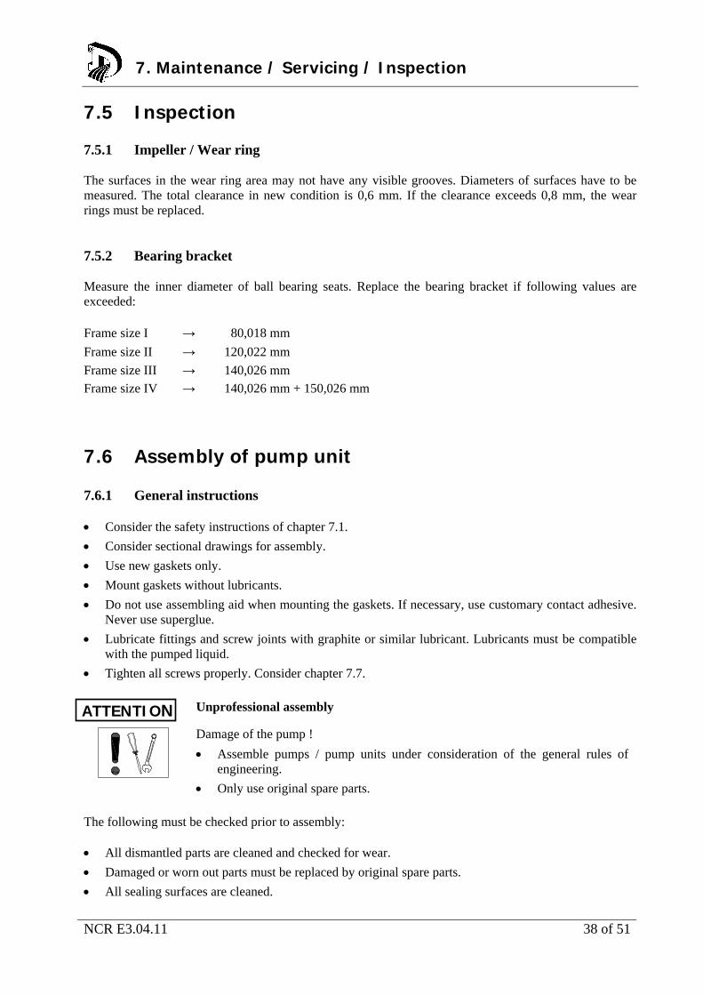
7.5 Inspection 7.5.1 Impeller / Wear ring The surfaces in the wear ring area may not have any visible grooves. Diameters of surfaces have to be measured. The total clearance in new condition is 0,6 mm. If the clearance exceeds 0,8 mm, the wear rings must be replaced. 7.5.2 Bearing bracket Measure the inner diameter of ball bearing seats. Replace the bearing bracket if following values are exceeded: Frame size I → 80,018 mm
Frame size II → 120,022 mm
Frame size III → 140,026 mm
Frame size IV → 140,026 mm + 150,026 mm
7.6 Assembly of pump unit 7.6.1 General instructions Consider the safety instructions of chapter 7.1.
Consider sectional drawings for assembly.
Use new gaskets only.
Mount gaskets without lubricants.
Do not use assembling aid when mounting the gaskets. If necessary, use customary contact adhesive. Never use superglue.
Lubricate fittings and screw joints with graphite or similar lubricant. Lubricants must be compatible with the pumped liquid.
Tighten all screws properly. Consider chapter 7.7.
Unprofessional assembly
Damage of the pump !
Assemble pumps / pump units under consideration of the general rules of engineering.
Only use original spare parts.
The following must be checked prior to assembly: All dismantled parts are cleaned and checked for wear.
Damaged or worn out parts must be replaced by original spare parts.
All sealing surfaces are cleaned.
7. Maintenance / Servicing / Inspection
ATTENTION

NCR E3.04.11 39 of 51
7.6.2 Assembly of antifriction bearings 1. Slide disk 550.1 onto the pump shaft.
2. Heat up the angular ball bearing 325 to 80-100°C.
3. Push the angular ball bearing 325 onto the pump shaft until limit.
Install the angular ball bearings in O-arrangement. Angular ball bearings installed in pairs must be of the same manufacturer.
4. Screw on the shaft nut 921 and tighten it.
5. Press the outer ring of the cylinder roller bearing 322 into the bearing bracket 330.
6. Fit the bearing cover 360.2 with labyrinth seal 430.2 and tighten the inner hexagon cap screw 914.6.
7. Press the pump shaft 211 together with the angular ball bearing 325 into the bearing bracket seat. Use a press- or drilling spindle.
8. Fit the bearing cover 360.1 with labyrinth seal 430.1 and tighten the inner hexagon cap screw 914.5.
7.6.3 Assembly of mechanical seal The works according to chapter 7.6.2 are completed. Installation requires attention of the following: Consider the seal drawing.
Works must be performed proper and thoroughly.
Never apply lubricants to sliding surfaces.
Never compress the metal bellows to a block.
Check parallelism with the casing part after assembly.
1. Push the complete seal unit 433 onto the pump shaft.
2. Press the intermediate casing 133 into the centring and fasten it.
3. Screw the seal unit 433 to the intermediate casing 113 by hexagon nuts 920.5.
4. Tighten the grub screws and loosen the assembly gauges.
NOTE
7. Maintenance / Servicing / Inspection
NCR E3.04.11 40 of 51
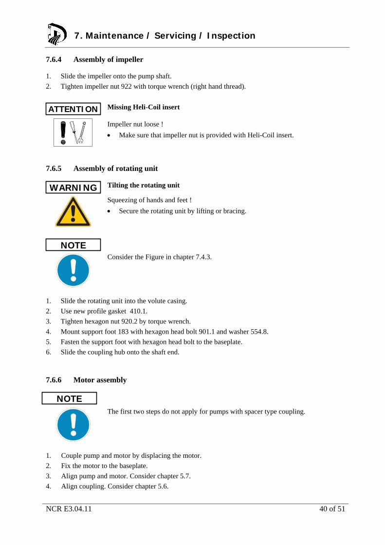
7.6.4 Assembly of impeller 1. Slide the impeller onto the pump shaft.
2. Tighten impeller nut 922 with torque wrench (right hand thread).
Missing Heli-Coil insert
Impeller nut loose !
Make sure that impeller nut is provided with Heli-Coil insert.
7.6.5 Assembly of rotating unit Tilting the rotating unit
Squeezing of hands and feet !
Secure the rotating unit by lifting or bracing.
Consider the Figure in chapter 7.4.3.
1. Slide the rotating unit into the volute casing.
2. Use new profile gasket 410.1.
3. Tighten hexagon nut 920.2 by torque wrench.
4. Mount support foot 183 with hexagon head bolt 901.1 and washer 554.8.
5. Fasten the support foot with hexagon head bolt to the baseplate.
6. Slide the coupling hub onto the shaft end.
7.6.6 Motor assembly
The first two steps do not apply for pumps with spacer type coupling.
1. Couple pump and motor by displacing the motor.
2. Fix the motor to the baseplate.
3. Align pump and motor. Consider chapter 5.7.
4. Align coupling. Consider chapter 5.6.
ATTENTION
WARNING
NOTE
7. Maintenance / Servicing / Inspection
NOTE
NCR E3.04.11 41 of 51
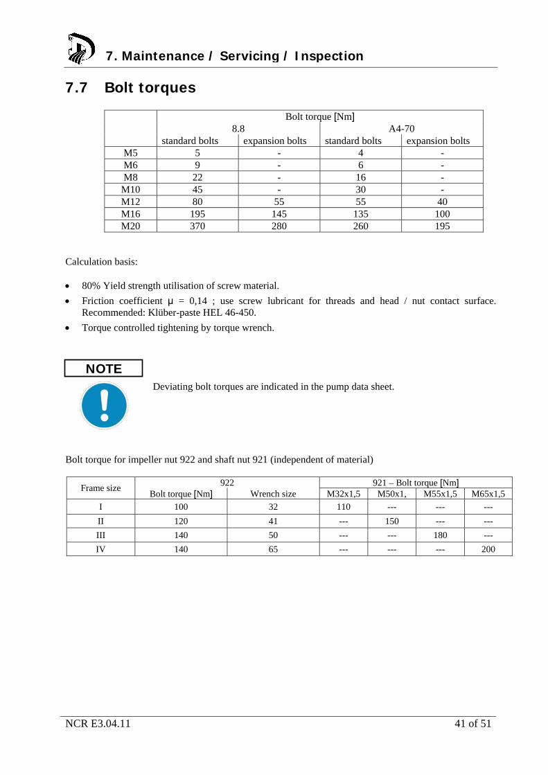
7.7 Bolt torques
Bolt torque [Nm] 8.8 A4-70
standard bolts expansion bolts standard bolts expansion bolts M5 5 - 4 - M6 9 - 6 - M8 22 - 16 -
M10 45 - 30 - M12 80 55 55 40 M16 195 145 135 100 M20 370 280 260 195
Calculation basis: 80% Yield strength utilisation of screw material.
Friction coefficient μ = 0,14 ; use screw lubricant for threads and head / nut contact surface. Recommended: Klüber-paste HEL 46-450.
Torque controlled tightening by torque wrench.
Deviating bolt torques are indicated in the pump data sheet.
Bolt torque for impeller nut 922 and shaft nut 921 (independent of material)
922 921 – Bolt torque [Nm] Frame size
Bolt torque [Nm] Wrench size M32x1,5 M50x1, M55x1,5 M65x1,5
I 100 32 110 --- --- ---
II 120 41 --- 150 --- ---
III 140 50 --- --- 180 ---
IV 140 65 --- --- --- 200
NOTE
7. Maintenance / Servicing / Inspection
NCR E3.04.11 42 of 51
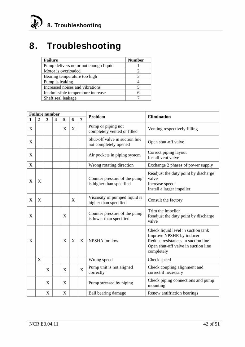
8. Troubleshooting
Failure Number Pump delivers no or not enough liquid 1 Motor is overloaded 2 Bearing temperature too high 3 Pump is leaking 4 Increased noises and vibrations 5 Inadmissible temperature increase 6 Shaft seal leakage 7
Failure number 1 2 3 4 5 6 7
Problem Elimination
X X X Pump or piping not completely vented or filled
Venting respectively filling
X Shut-off valve in suction line not completely opened
Open shut-off valve
X Air pockets in piping system Correct piping layout Install vent valve
X Wrong rotating direction Exchange 2 phases of power supply
X X Counter pressure of the pump is higher than specified
Readjust the duty point by discharge valve Increase speed Install a larger impeller
X X X Viscosity of pumped liquid is higher than specified
Consult the factory
X X Counter pressure of the pump is lower than specified
Trim the impeller Readjust the duty point by discharge valve
X X X X NPSHA too low
Check liquid level in suction tank Improve NPSHR by inducer Reduce resistances in suction line Open shut-off valve in suction line completely
X Wrong speed Check speed
X X X Pump unit is not aligned correctly
Check coupling alignment and correct if necessary
X X Pump stressed by piping Check piping connections and pump mounting
X X Ball bearing damage Renew antifriction bearings
8. Troubleshooting
NCR E3.04.11 43 of 51
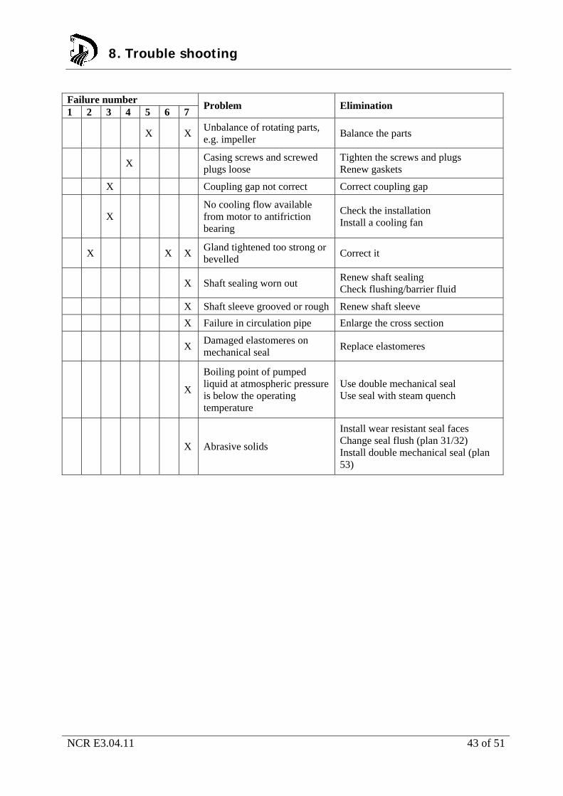
Failure number 1 2 3 4 5 6 7
Problem Elimination
X X Unbalance of rotating parts, e.g. impeller
Balance the parts
X Casing screws and screwed plugs loose
Tighten the screws and plugs Renew gaskets
X Coupling gap not correct Correct coupling gap
X No cooling flow available from motor to antifriction bearing
Check the installation Install a cooling fan
X X X Gland tightened too strong or bevelled
Correct it
X Shaft sealing worn out Renew shaft sealing Check flushing/barrier fluid
X Shaft sleeve grooved or rough Renew shaft sleeve
X Failure in circulation pipe Enlarge the cross section
X Damaged elastomeres on mechanical seal
Replace elastomeres
X
Boiling point of pumped liquid at atmospheric pressure is below the operating temperature
Use double mechanical seal Use seal with steam quench
X Abrasive solids
Install wear resistant seal faces Change seal flush (plan 31/32) Install double mechanical seal (plan 53)
8. Trouble shooting
NCR E3.04.11 44 of 51
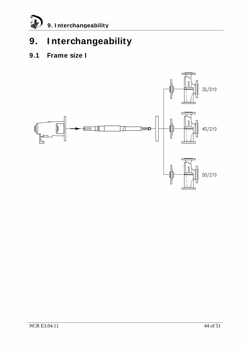
9. Interchangeability 9.1 Frame size I
9. Interchangeability
NCR E3.04.11 45 of 51
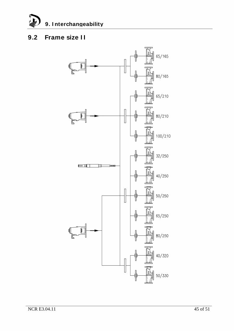
9.2 Frame size II
9. Interchangeability
NCR E3.04.11 46 of 51
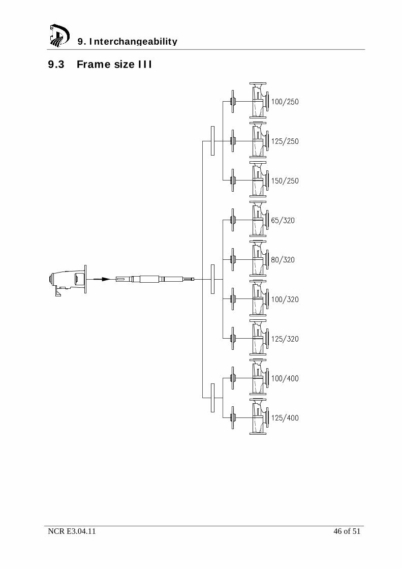
9.3 Frame size III
9. Interchangeability
NCR E3.04.11 47 of 51
9.4 Frame size IV
9. Interchangeability
NCR E3.04.11 48 of 51
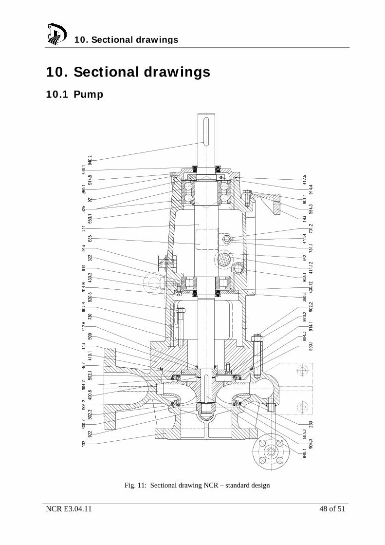
10. Sectional drawings 10.1 Pump
Fig. 11: Sectional drawing NCR – standard design
10. Sectional drawings
NCR E3.04.11 49 of 51
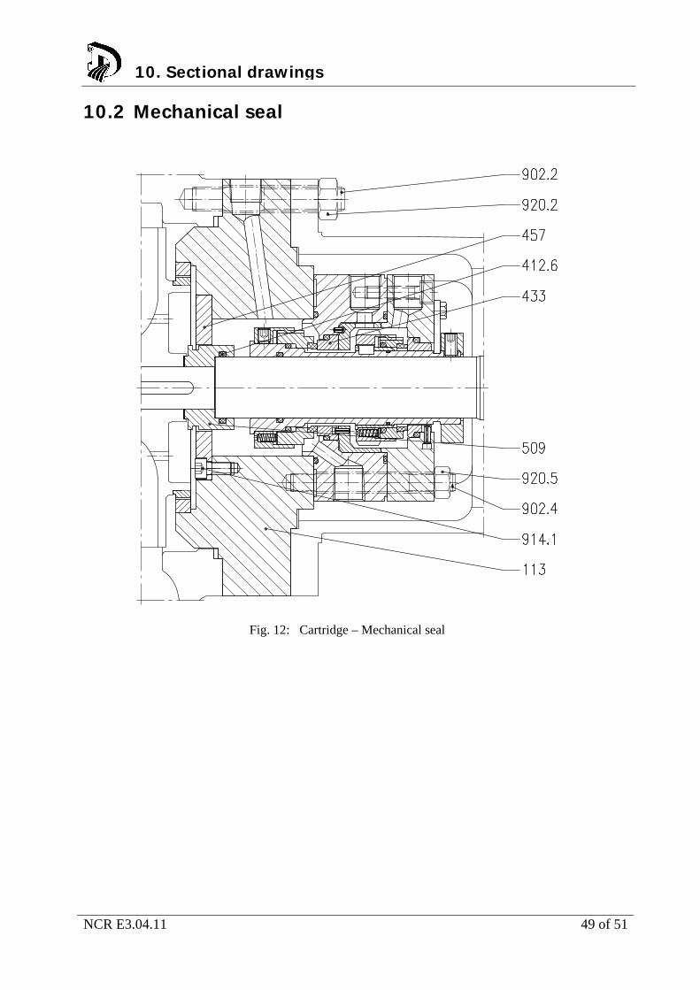
10.2 Mechanical seal
Fig. 12: Cartridge – Mechanical seal
10. Sectional drawings
NCR E3.04.11 50 of 51
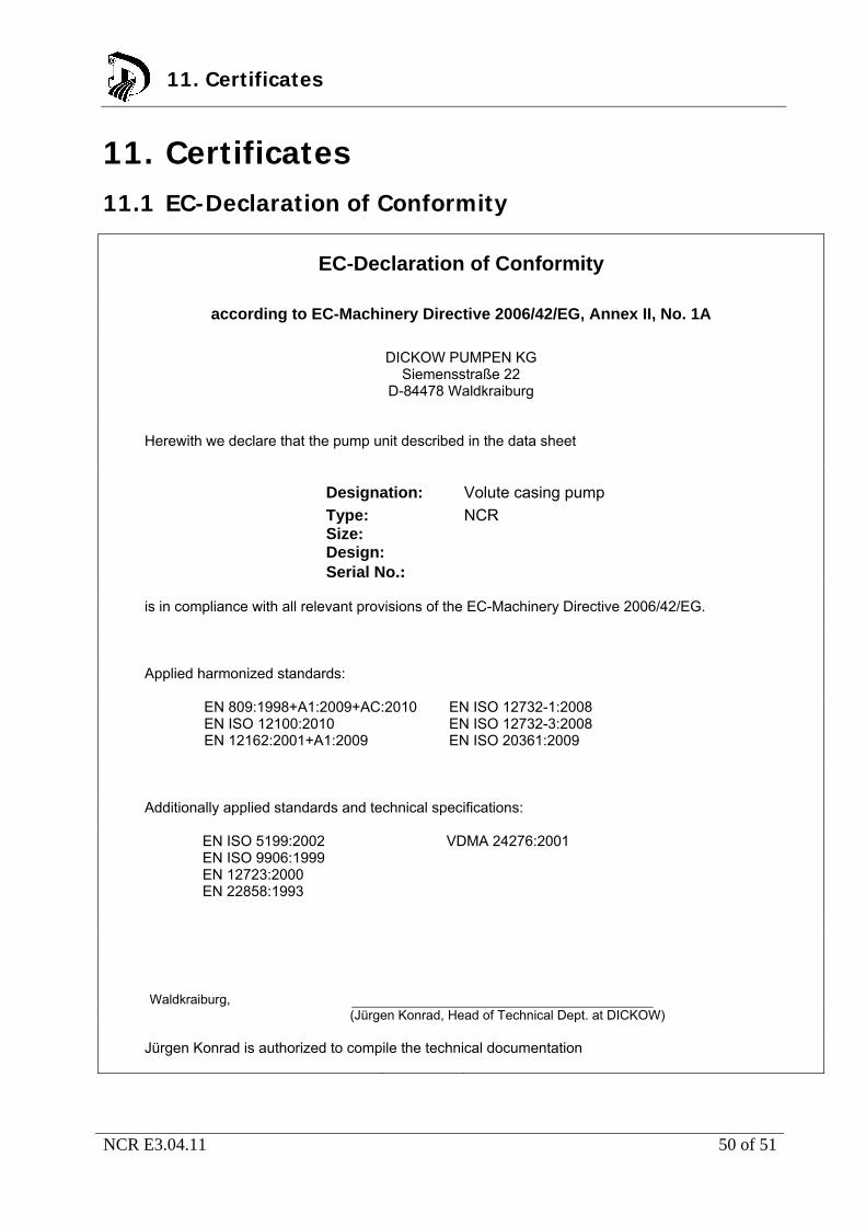
11. Certificates 11.1 EC-Declaration of Conformity
EC-Declaration of Conformity
according to EC-Machinery Directive 2006/42/EG, Annex II, No. 1A
DICKOW PUMPEN KG
Siemensstraße 22 D-84478 Waldkraiburg
Herewith we declare that the pump unit described in the data sheet
Designation: Volute casing pump
Type: NCR Size: Design: Serial No.:
is in compliance with all relevant provisions of the EC-Machinery Directive 2006/42/EG.
Applied harmonized standards: EN 809:1998+A1:2009+AC:2010
EN ISO 12100:2010 EN 12162:2001+A1:2009
EN ISO 12732-1:2008 EN ISO 12732-3:2008 EN ISO 20361:2009
Additionally applied standards and technical specifications:
EN ISO 5199:2002 EN ISO 9906:1999 EN 12723:2000 EN 22858:1993
VDMA 24276:2001
Waldkraiburg,
(Jürgen Konrad, Head of Technical Dept. at DICKOW) Jürgen Konrad is authorized to compile the technical documentation
11. Certificates
NCR E3.04.11 51 of 51
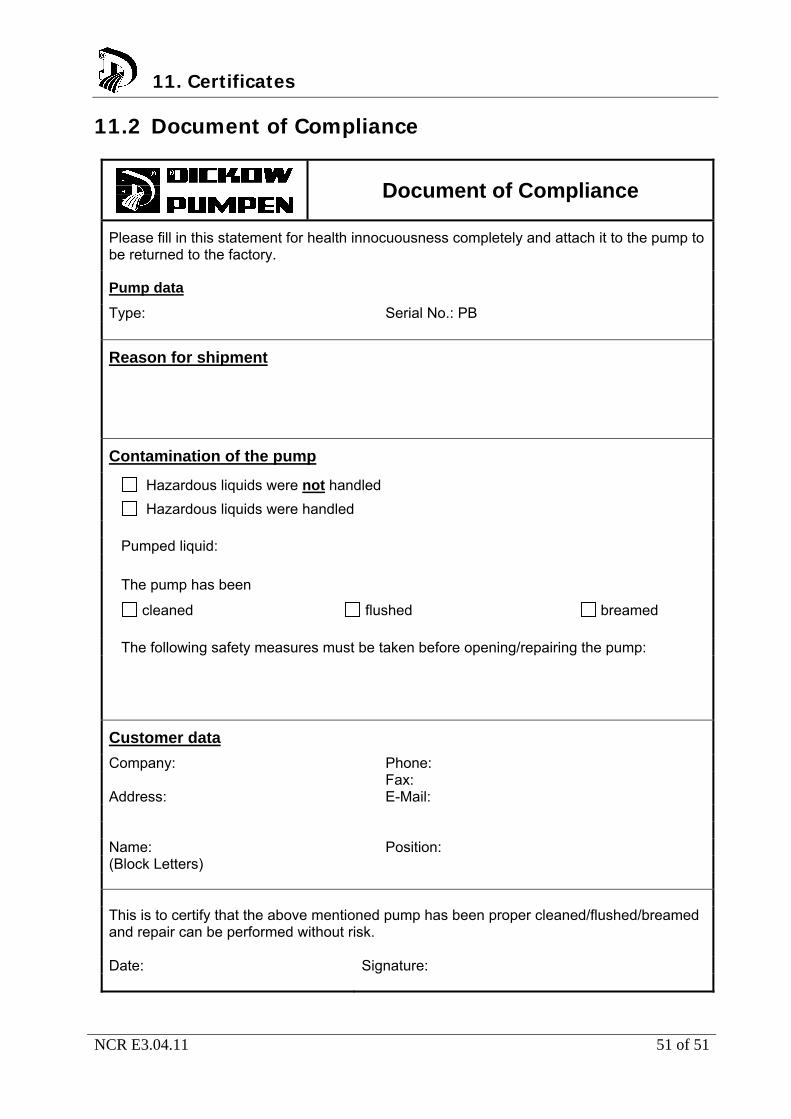
11.2 Document of Compliance
Document of Compliance
Please fill in this statement for health innocuousness completely and attach it to the pump to be returned to the factory.
Pump data
Type: Serial No.: PB
Reason for shipment
Contamination of the pump
Hazardous liquids were not handled
Hazardous liquids were handled Pumped liquid:
The pump has been
cleaned flushed breamed
The following safety measures must be taken before opening/repairing the pump:
Customer data
Company: Phone:
Fax:
Address: E-Mail:
Name: Position: (Block Letters)
This is to certify that the above mentioned pump has been proper cleaned/flushed/breamed and repair can be performed without risk. Date: Signature:
11. Certificates